JP2021146014A - Game machine - Google Patents
Game machine Download PDFInfo
- Publication number
- JP2021146014A JP2021146014A JP2020050427A JP2020050427A JP2021146014A JP 2021146014 A JP2021146014 A JP 2021146014A JP 2020050427 A JP2020050427 A JP 2020050427A JP 2020050427 A JP2020050427 A JP 2020050427A JP 2021146014 A JP2021146014 A JP 2021146014A
- Authority
- JP
- Japan
- Prior art keywords
- shows
- medal
- game
- control board
- reel
- Prior art date
- Legal status (The legal status is an assumption and is not a legal conclusion. Google has not performed a legal analysis and makes no representation as to the accuracy of the status listed.)
- Pending
Links
- 230000007704 transition Effects 0.000 claims description 141
- 230000001186 cumulative effect Effects 0.000 claims description 31
- 238000000034 method Methods 0.000 description 1826
- 230000008569 process Effects 0.000 description 1772
- 230000000694 effects Effects 0.000 description 645
- 230000008859 change Effects 0.000 description 506
- 238000012545 processing Methods 0.000 description 483
- 230000000875 corresponding effect Effects 0.000 description 445
- 238000003860 storage Methods 0.000 description 255
- 238000003780 insertion Methods 0.000 description 205
- 230000037431 insertion Effects 0.000 description 205
- 238000007726 management method Methods 0.000 description 169
- 238000001514 detection method Methods 0.000 description 166
- 238000003825 pressing Methods 0.000 description 144
- 238000010586 diagram Methods 0.000 description 135
- 230000006870 function Effects 0.000 description 133
- 241000219109 Citrullus Species 0.000 description 109
- 235000012828 Citrullus lanatus var citroides Nutrition 0.000 description 109
- 238000004364 calculation method Methods 0.000 description 108
- WABPQHHGFIMREM-UHFFFAOYSA-N lead(0) Chemical compound [Pb] WABPQHHGFIMREM-UHFFFAOYSA-N 0.000 description 105
- 244000208734 Pisonia aculeata Species 0.000 description 103
- 241000167854 Bourreria succulenta Species 0.000 description 90
- 235000019693 cherries Nutrition 0.000 description 90
- 238000004519 manufacturing process Methods 0.000 description 90
- 238000007792 addition Methods 0.000 description 84
- 238000012360 testing method Methods 0.000 description 84
- 238000012790 confirmation Methods 0.000 description 82
- 230000005284 excitation Effects 0.000 description 71
- 230000006854 communication Effects 0.000 description 63
- 238000004891 communication Methods 0.000 description 63
- 230000000630 rising effect Effects 0.000 description 59
- 239000000872 buffer Substances 0.000 description 50
- 239000003990 capacitor Substances 0.000 description 45
- 238000002360 preparation method Methods 0.000 description 44
- 239000000758 substrate Substances 0.000 description 42
- PZTQVMXMKVTIRC-UHFFFAOYSA-L chembl2028348 Chemical compound [Ca+2].[O-]S(=O)(=O)C1=CC(C)=CC=C1N=NC1=C(O)C(C([O-])=O)=CC2=CC=CC=C12 PZTQVMXMKVTIRC-UHFFFAOYSA-L 0.000 description 40
- 230000001133 acceleration Effects 0.000 description 36
- 238000011084 recovery Methods 0.000 description 32
- 238000012986 modification Methods 0.000 description 29
- 230000004048 modification Effects 0.000 description 29
- 230000002441 reversible effect Effects 0.000 description 29
- 230000002093 peripheral effect Effects 0.000 description 26
- 239000002243 precursor Substances 0.000 description 26
- 230000002265 prevention Effects 0.000 description 26
- 230000009471 action Effects 0.000 description 22
- 230000005540 biological transmission Effects 0.000 description 22
- 238000012544 monitoring process Methods 0.000 description 19
- 239000011347 resin Substances 0.000 description 19
- 229920005989 resin Polymers 0.000 description 19
- 238000012937 correction Methods 0.000 description 17
- 230000002159 abnormal effect Effects 0.000 description 16
- 230000005281 excited state Effects 0.000 description 16
- 230000007423 decrease Effects 0.000 description 15
- 238000013461 design Methods 0.000 description 15
- 239000011521 glass Substances 0.000 description 15
- 230000002829 reductive effect Effects 0.000 description 15
- 238000007689 inspection Methods 0.000 description 14
- XLYOFNOQVPJJNP-UHFFFAOYSA-N water Substances O XLYOFNOQVPJJNP-UHFFFAOYSA-N 0.000 description 14
- 230000005856 abnormality Effects 0.000 description 12
- 230000001276 controlling effect Effects 0.000 description 11
- 230000003111 delayed effect Effects 0.000 description 10
- 230000001965 increasing effect Effects 0.000 description 10
- 238000011144 upstream manufacturing Methods 0.000 description 10
- 230000004397 blinking Effects 0.000 description 9
- 238000010924 continuous production Methods 0.000 description 9
- 239000008151 electrolyte solution Substances 0.000 description 9
- 238000005520 cutting process Methods 0.000 description 8
- 230000003287 optical effect Effects 0.000 description 8
- 229910000679 solder Inorganic materials 0.000 description 8
- 230000007547 defect Effects 0.000 description 7
- 238000007599 discharging Methods 0.000 description 7
- 238000005259 measurement Methods 0.000 description 7
- 238000000465 moulding Methods 0.000 description 7
- 238000012546 transfer Methods 0.000 description 7
- 238000000605 extraction Methods 0.000 description 6
- 238000007562 laser obscuration time method Methods 0.000 description 6
- 239000004973 liquid crystal related substance Substances 0.000 description 6
- 230000014759 maintenance of location Effects 0.000 description 6
- 230000007246 mechanism Effects 0.000 description 6
- 238000013508 migration Methods 0.000 description 6
- 230000005012 migration Effects 0.000 description 6
- 230000003213 activating effect Effects 0.000 description 5
- 238000009826 distribution Methods 0.000 description 5
- 230000001976 improved effect Effects 0.000 description 5
- 238000012423 maintenance Methods 0.000 description 5
- 238000013500 data storage Methods 0.000 description 4
- 238000010304 firing Methods 0.000 description 4
- 230000001788 irregular Effects 0.000 description 4
- 238000012795 verification Methods 0.000 description 4
- 208000001613 Gambling Diseases 0.000 description 3
- 230000004913 activation Effects 0.000 description 3
- 230000002844 continuous effect Effects 0.000 description 3
- 230000029087 digestion Effects 0.000 description 3
- 230000007257 malfunction Effects 0.000 description 3
- 239000000463 material Substances 0.000 description 3
- 229910052751 metal Inorganic materials 0.000 description 3
- 239000002184 metal Substances 0.000 description 3
- 238000012806 monitoring device Methods 0.000 description 3
- 238000004904 shortening Methods 0.000 description 3
- 238000004088 simulation Methods 0.000 description 3
- 230000001360 synchronised effect Effects 0.000 description 3
- 241000722921 Tulipa gesneriana Species 0.000 description 2
- 238000004458 analytical method Methods 0.000 description 2
- 230000008901 benefit Effects 0.000 description 2
- 230000000903 blocking effect Effects 0.000 description 2
- 239000003086 colorant Substances 0.000 description 2
- 230000003247 decreasing effect Effects 0.000 description 2
- 230000005484 gravity Effects 0.000 description 2
- 230000012447 hatching Effects 0.000 description 2
- 238000002347 injection Methods 0.000 description 2
- 239000007924 injection Substances 0.000 description 2
- 230000013011 mating Effects 0.000 description 2
- 230000001151 other effect Effects 0.000 description 2
- 230000002250 progressing effect Effects 0.000 description 2
- 230000004044 response Effects 0.000 description 2
- 230000000717 retained effect Effects 0.000 description 2
- 238000007789 sealing Methods 0.000 description 2
- 230000003068 static effect Effects 0.000 description 2
- 241000616862 Belliella Species 0.000 description 1
- 101100129500 Caenorhabditis elegans max-2 gene Proteins 0.000 description 1
- 241000283707 Capra Species 0.000 description 1
- 241001391944 Commicarpus scandens Species 0.000 description 1
- 101100083446 Danio rerio plekhh1 gene Proteins 0.000 description 1
- 125000002066 L-histidyl group Chemical group [H]N1C([H])=NC(C([H])([H])[C@](C(=O)[*])([H])N([H])[H])=C1[H] 0.000 description 1
- 238000013459 approach Methods 0.000 description 1
- 230000004888 barrier function Effects 0.000 description 1
- 230000007175 bidirectional communication Effects 0.000 description 1
- 230000033228 biological regulation Effects 0.000 description 1
- 230000000295 complement effect Effects 0.000 description 1
- 150000001875 compounds Chemical class 0.000 description 1
- 230000006835 compression Effects 0.000 description 1
- 238000007906 compression Methods 0.000 description 1
- 238000001816 cooling Methods 0.000 description 1
- 239000013256 coordination polymer Substances 0.000 description 1
- 230000002950 deficient Effects 0.000 description 1
- 238000009795 derivation Methods 0.000 description 1
- 238000011161 development Methods 0.000 description 1
- 230000018109 developmental process Effects 0.000 description 1
- 230000005611 electricity Effects 0.000 description 1
- VUFOSBDICLTFMS-UHFFFAOYSA-M ethyl-hexadecyl-dimethylazanium;bromide Chemical compound [Br-].CCCCCCCCCCCCCCCC[N+](C)(C)CC VUFOSBDICLTFMS-UHFFFAOYSA-M 0.000 description 1
- 239000000284 extract Substances 0.000 description 1
- 230000002349 favourable effect Effects 0.000 description 1
- 210000004247 hand Anatomy 0.000 description 1
- 210000003128 head Anatomy 0.000 description 1
- 230000001771 impaired effect Effects 0.000 description 1
- 238000009434 installation Methods 0.000 description 1
- 230000002452 interceptive effect Effects 0.000 description 1
- 238000011068 loading method Methods 0.000 description 1
- 230000000873 masking effect Effects 0.000 description 1
- 229910052757 nitrogen Inorganic materials 0.000 description 1
- 230000000149 penetrating effect Effects 0.000 description 1
- 230000035515 penetration Effects 0.000 description 1
- 229910052698 phosphorus Inorganic materials 0.000 description 1
- 238000007639 printing Methods 0.000 description 1
- 230000009467 reduction Effects 0.000 description 1
- 230000001105 regulatory effect Effects 0.000 description 1
- 230000009747 swallowing Effects 0.000 description 1
- 230000001960 triggered effect Effects 0.000 description 1
- 230000000007 visual effect Effects 0.000 description 1
- 230000003313 weakening effect Effects 0.000 description 1
- 230000002087 whitening effect Effects 0.000 description 1
Images


Abstract
Description
本発明は、遊技機に関するものである。 The present invention relates to a gaming machine.
従来より、遊技機の1つとして、スロットマシンが知られている(たとえば、特許文献1参照)。 Conventionally, a slot machine has been known as one of the gaming machines (see, for example, Patent Document 1).
本発明が解決しようとする課題は、遊技機としての性能を向上させることである。 The problem to be solved by the present invention is to improve the performance as a gaming machine.
本発明は、以下の解決手段によって上述の課題を解決する(かっこ書きで、対応する実施形態の構成を示す。)。なお、本発明は、後述する当初発明1〜10のうち、当初発明1に相当する。
本発明(第50実施形態)は、
遊技の進行を制御するメイン制御手段(50)を備え、
報知遊技の実行権利を付与する確率が所定確率(「小役I条件装置」〜「小役V条件装置」作動時のAT抽選の当選確率が「10%」)の第1区間(非チャンスゾーン)と、
報知遊技の実行権利を付与する確率が第1区間より高い(「小役I条件装置」〜「小役V条件装置」作動時のAT抽選の当選確率が「80%」)第2区間(チャンスゾーン)と
を有し、
前記メイン制御手段は、
第1区間において第2区間に移行させるか否かの移行抽選を実行可能とし、前記移行抽選に当選したときは、第1区間から第2区間に移行させ、
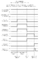
所定時(有利区間移行時)からの遊技回数の累計が所定遊技回数(500遊技)に到達したことに基づいて、第1区間から第2区間に移行可能とし、
前記移行抽選に当選したことに基づいて第1区間から第2区間に移行させるときは、外部信号を出力せず(図513)、前記所定時からの遊技回数が前記所定遊技回数に到達したことに基づいて第1区間から第2区間に移行させるときは、外部信号を出力する(図511)
ことを特徴とする。
The present invention solves the above-mentioned problems by the following means (in parentheses, the configuration of the corresponding embodiment is shown). The present invention corresponds to the
The present invention (50th embodiment)
Equipped with a main control means (50) for controlling the progress of the game
The first section (non-chance zone) in which the probability of granting the right to execute the notification game is a predetermined probability (the probability of winning the AT lottery when the "small combination I condition device" to "small combination V condition device" is activated is "10%"). )When,
The probability of granting the right to execute the notification game is higher than that of the first section (the probability of winning the AT lottery when the "small combination I condition device" to "small combination V condition device" is operating is "80%"). Zone) and has
The main control means
In the first section, a transition lottery for whether or not to shift to the second section can be executed, and when the transition lottery is won, the transition from the first section to the second section is performed.
Based on the cumulative number of games played from the predetermined time (when shifting to the advantageous section) reaches the predetermined number of games (500 games), it is possible to shift from the first section to the second section.
When shifting from the first section to the second section based on winning the transition lottery, no external signal is output (FIG. 513), and the number of games from the predetermined time has reached the predetermined number of games. When shifting from the first section to the second section based on the above, an external signal is output (FIG. 511).
It is characterized by that.
本発明によれば、遊技機としての性能を向上させることができる。 According to the present invention, the performance as a gaming machine can be improved.
本明細書において、用語の意味は、以下の通りである。
「ベット」とは、遊技を行うためにメダル(遊技媒体)を賭けることをいう。メダルをベットするには、メダル投入口47から実際のメダルを手入れ投入するか、又はクレジット(貯留)されているメダルをベットするためにベットスイッチ40を操作する。
一方、「クレジット(「貯留」ともいう。)」とは、上記「ベット」とは異なり、スロットマシン10内部にメダルを貯留することをいう。本明細書では、「クレジット」というときは、「ベット」を含まない意味で使用する。
さらに、「投入」とは、メダルをベット又はクレジットすることをいう。
また、「規定数」とは、当該遊技で遊技を開始(実行)可能なベット数をいう。たとえば、規定数「2」又は「3」である遊技では、ベット数「2」又は「3」のいずれかで遊技を開始可能であり、ベット数「1」で遊技を行うことはできない。
なお、説明の便宜上、「規定数」を「ベット数」と称する場合もある。
一方、「ベット数」というときは、「規定数」以外を指す場合もある。たとえば規定数「2」又は「3」の遊技において、1枚のメダルが投入された時点(遊技開始前)では、ベット数は「1」(その時点でベットされている数)である。
In the present specification, the meanings of the terms are as follows.
"Bet" means betting a medal (game medium) in order to play a game. To bet a medal, the actual medal is groomed and inserted from the
On the other hand, "credit (also referred to as" storage ")" means storing medals inside the
Further, "insertion" means betting or crediting a medal.
Further, the "specified number" means the number of bets that can start (execute) the game in the game. For example, in a game in which the specified number is "2" or "3", the game can be started with either the bet number "2" or "3", and the game cannot be played with the bet number "1".
For convenience of explanation, the "specified number" may be referred to as the "bet number".
On the other hand, the term "number of bets" may refer to something other than the "specified number". For example, in a game with a specified number of "2" or "3", when one medal is inserted (before the start of the game), the number of bets is "1" (the number bet at that time).
「手入れ」とは、遊技者が、メダル投入口47(後述)からメダルを投入することをいう。
「手入れベット」とは、遊技者が、メダル投入口47からメダルを手入れすることにより、メダルをベットすることをいう。
「手入れクレジット」とは、遊技者が、メダル投入口47からメダルを手入れすることにより、メダルをクレジットすること(クレジットを加算する)ことをいう。
「ベットメダル」とは、ベットされているメダルをいう。
「貯留メダル」とは、クレジット(貯留)されているメダルをいう。
"Maintenance" means that the player inserts medals from the medal insertion slot 47 (described later).
The "care bet" means that the player bets a medal by caring for the medal from the
The "care credit" means that the player credits the medal (adds credit) by caring for the medal from the
"Bet medal" means a medal that has been bet.
"Reserved medal" means a medal that is credited (stored).
「貯留ベット」とは、遊技者がベットスイッチ40(後述)を操作することにより、当該遊技でベット可能な範囲内において、クレジットされているメダルの一部又は全部を、遊技を行うためにベットすることをいう。
「自動ベット」とは、リプレイが入賞したときに、スロットマシン10の制御処理により、前回遊技でベットされていた数のメダルを自動でベットすることをいう。
ここで、小役に対応する図柄組合せが停止表示(有効ラインに停止したことを意味する。以下同じ。)したことを「小役の入賞」と称する。一方、「遊技機の認定及び型式の検定等に関する規則(以下、単に「規則」という。)」では、リプレイに対応する図柄組合せが停止表示したときは、再遊技に係る条件装置の作動であって「入賞」ではないと解釈されている。しかし、本願(本明細書等)では、リプレイについても役の1つとして扱い(再遊技役)、リプレイに対応する図柄組合せが停止表示したことを「リプレイの入賞」と称する場合がある。
「精算」とは、ベットメダル及び/又は貯留メダルを遊技者に対して払い出すことをいう。本実施形態では、精算スイッチ43(後述)が操作されたときに精算処理を実行する。
The "storage bet" is a bet for playing a part or all of the credited medals within the range where the player can bet in the game by operating the bet switch 40 (described later). To do.
The "automatic bet" means that when the replay wins, the number of medals bet in the previous game is automatically bet by the control process of the
Here, the fact that the symbol combination corresponding to the small winning combination is stopped and displayed (meaning that it has stopped at the valid line. The same shall apply hereinafter) is referred to as "small winning combination". On the other hand, in the "Rules for certification of gaming machines and type verification (hereinafter, simply referred to as" rules ")", when the symbol combination corresponding to the replay is stopped and displayed, the condition device related to the replay is activated. It is interpreted that it is not a "winning prize". However, in the present application (the present specification, etc.), the replay is also treated as one of the roles (replaying role), and the stop display of the symbol combination corresponding to the replay may be referred to as "replay winning".
"Payment" means paying out bet medals and / or stored medals to the player. In the present embodiment, the settlement process is executed when the settlement switch 43 (described later) is operated.
「払出し」とは、役の入賞に基づきメダルを遊技者に払い出すこと、又は上記精算によりメダルを払い出すことをいう。役の入賞に基づきメダルを遊技者に払い出すときは、クレジットとして貯留すること(貯留メダルを加算すること、換言すれば、RWM53(後述)に記憶された電子データを更新すること)、及び払出し口(図示せず)から実際のメダルを払い出すことの双方を含む。メダルの払出しは、たとえば「50」枚を限界枚数としてクレジットし、クレジット数が「50」を超えた分のメダルは、遊技者に対して実際に払い出すように制御する。
なお、「払出し」を、「付与」と称する場合もある。したがって、「払出し数」を「付与数」と称する場合もある。
"Payout" means paying out medals to the player based on the winning of the role, or paying out the medals by the above settlement. When paying out medals to players based on winning a role, store them as credits (adding stored medals, in other words, updating the electronic data stored in RWM53 (described later)) and paying out. Includes both paying out the actual medal by mouth (not shown). For example, "50" medals are credited as the limit number of medals, and medals for which the number of credits exceeds "50" are controlled to be actually paid out to the player.
In addition, "payout" may be referred to as "grant". Therefore, the "number of payouts" may be referred to as the "number of grants".
「遊技媒体」は、本実施形態ではメダルであるが、たとえば封入式(ECO)遊技機のような場合には、遊技媒体として電子情報(電子メダル、電子データ)が用いられる。なお、「電子情報」とは、たとえば貸出し機に金銭(紙幣)を投入すると、その金銭に対応する分の電子情報に変換されるとともに、その電子情報の一部又は全部を、遊技機で遊技を行うための遊技媒体として遊技機にクレジット可能となるものである。
なお、「遊技媒体」は、「遊技価値」と称する場合もある。
The "game medium" is a medal in the present embodiment, but in the case of, for example, an enclosed (ECO) gaming machine, electronic information (electronic medal, electronic data) is used as the game medium. The "electronic information" means, for example, that when money (banknotes) is inserted into a lending machine, it is converted into electronic information corresponding to the money, and a part or all of the electronic information is played on the gaming machine. It is possible to credit the gaming machine as a gaming medium for performing the above.
The "game medium" may also be referred to as "game value".
また、遊技媒体が電子情報である場合において、「メダルの払出し」とは、遊技機に備えられた遊技媒体クレジット装置にクレジット(加算)することを意味する。したがって、「メダルの払出し」とは、実際にメダルをホッパー35(後述)から払い出すことのみを意味するものではなく、遊技媒体クレジット装置に、入賞役に対応する配当分の電子情報をクレジット(加算)する処理も含まれる。 Further, when the game medium is electronic information, "payout of medals" means crediting (adding) to the game medium credit device provided in the game machine. Therefore, "paying out medals" does not mean only actually paying out medals from the hopper 35 (described later), but credits the game medium credit device with the electronic information of the dividend corresponding to the winning combination (payout of medals). The process of adding) is also included.
「N−1」遊技目、「N」遊技目、「N+1」遊技目、・・・(「N」は、2以上の整数)と遊技が進行する場合において、現在の遊技が「N」遊技目であるとき、「N」遊技目の遊技を「今回遊技」と称する。また、「N−1」遊技目の遊技を「前回遊技」と称する。さらにまた、「N+1」遊技目の遊技を「次回遊技」と称する。 When the game progresses with "N-1" game, "N" game, "N + 1" game, ... ("N" is an integer of 2 or more), the current game is "N" game. When it is an eye, the game of the "N" game is referred to as "this time game". Further, the game of the "N-1" game is referred to as a "previous game". Furthermore, the game of the "N + 1" game is referred to as the "next game".
本明細書において、数字の末尾(特に、8ビット)に「(B)」を付した数値は、2進数を意味する。同様に、数字の末尾に「(H)」、「H」又は「h」を付した数値は、16進数を意味する。具体的には、たとえば10進数で「16」を示す数値は、2進数では「00010000(B)」と表記し、16進数では「10(H)」、「10H」又は「10h」と表記する。また、10進数を意味する数値については、必要に応じて「16(D)」と表記する。
ただし、2進数、10進数、及び16進数のいずれであるかが明確であるときは、それぞれ「(B)」、「(D)」、「(H)」、「H」又は「h」の末尾記号を省略する場合がある。
In the present specification, a numerical value in which "(B)" is added to the end of a number (particularly, 8 bits) means a binary number. Similarly, a number with "(H)", "H" or "h" at the end of the number means a hexadecimal number. Specifically, for example, a numerical value indicating "16" in decimal is expressed as "00010000 (B)" in binary, and is expressed as "10 (H)", "10H" or "10h" in hexadecimal. .. Further, a numerical value meaning a decimal number is expressed as "16 (D)" as necessary.
However, when it is clear whether it is a binary number, a decimal number, or a hexadecimal number, "(B)", "(D)", "(H)", "H", or "h", respectively. The trailing symbol may be omitted.
ストップスイッチ42の「操作態様」とは、ストップスイッチ42の押し順、及び/又は操作タイミング(対象図柄が有効ラインに停止するためのストップスイッチの押すタイミング)を意味する。
また、ストップスイッチ42の「有利な操作態様」とは、ストップスイッチ42の操作態様によって遊技結果(有効ラインに停止する図柄組合せ)に有利/不利が生じる遊技において、払出しを有する若しくは払出し数の多い図柄組合せが停止する操作態様、有利なRTに移行(昇格)する図柄組合せが停止する操作態様、又は不利なRTに移行(転落)しない図柄組合せが停止する操作態様をいう。「有利な操作態様」は、正解操作態様、正解押し順とも称される。
The "operation mode" of the
Further, the "advantageous operation mode" of the
「ストップスイッチ42の操作態様によって遊技結果に有利/不利が生じる遊技」は、たとえば後述する図58に示す当選番号「3」〜「8」のいずれかに当選した遊技(いわゆる「押し順ベル」に当選した遊技)に相当する。また、図58では図示していないが、たとえば複数種類のリプレイに当選した遊技(重複リプレイ当選時。いわゆる「押し順リプレイ」に当選した遊技)において、入賞したリプレイの種類によってRTが移行するような場合も相当する。
The "game in which the game result is advantageous / disadvantageous depending on the operation mode of the
「指示機能」とは、ストップスイッチ42の操作態様を遊技者に指示する機能を意味する。指示機能は、原則として、ストップスイッチ42の有利な操作態様を遊技者に指示する機能である。
いいかえれば、「指示機能」は、入賞を容易にする装置を指す。
なお、「指示」内容を見えるように示すことが「表示」であり、指示内容を遊技者に知らせることが「報知」である。よって、「指示機能」は、「表示機能」でもあり、「報知機能」でもある。
The "instruction function" means a function of instructing the player of the operation mode of the
In other words, the "instruction function" refers to a device that facilitates winning.
It should be noted that "display" is to show the content of the "instruction" so that it can be seen, and "notification" is to inform the player of the content of the instruction. Therefore, the "instruction function" is both a "display function" and a "notification function".
また、ストップスイッチ42の操作態様の報知は、最も有利となる操作態様の報知に限らない可能性がある。そして、最も有利となるストップスイッチ42の操作態様の報知を「指示機能の作動」としてもよいが、最も有利となるストップスイッチ42の操作態様を含むいずれかの操作態様の報知を「指示機能の作動」としてもよい。
たとえば、後述する図58(B)の当選番号「3」〜「8」に示す押し順ベルが6択押し順である場合、その押し順ベル当選時の配当は図58の例では10枚又は1枚であるが、これに代えて、押し順に応じて、1枚、3枚、4枚、10枚、又は取りこぼし(非入賞)のいずれかになると仮定する。
ここで、10枚役を入賞させるための押し順を報知することは、ストップスイッチ42の有利な操作態様の報知であり、「指示機能の作動」に該当することはもちろんである。
一方、1枚役、3枚役、又は4枚役を入賞させるための押し順を報知することを、「有利な操作態様の報知(指示機能の作動)」としてもよく、「有利な操作態様の報知」としなくてもよい。
Further, the notification of the operation mode of the
For example, if the push order bells shown in the winning numbers "3" to "8" in FIG. 58 (B), which will be described later, are in the 6-choice push order, the payout at the time of winning the push order bell is 10 or 10 in the example of FIG. Although it is one, it is assumed that instead of this, one, three, four, ten, or missed (non-winning) is obtained depending on the pushing order.
Here, notifying the pressing order for winning the 10-card combination is a notification of an advantageous operation mode of the
On the other hand, notifying the push order for winning the 1-card combination, 3-card combination, or 4-card combination may be referred to as "notification of advantageous operation mode (operation of instruction function)", and "advantageous operation mode". It is not necessary to say "notification of".
4枚役を入賞させるための押し順は、10枚役を入賞させない押し順であるから、最も有利となる操作態様ではない。しかし、ベット数「3」に対して払出し数「4」となり、当該遊技の差枚数は「+1」となるから、差枚数を増加させる操作態様であり、必ずしも不利な操作態様とはいえない。
同様に、3枚役を入賞させるための押し順は、10枚役を入賞させない押し順であるから、最も有利な操作態様ではない。しかし、ベット数「3」に対して払出し数「3」となり、差枚数を現状維持する(差枚数を減少させない)操作態様であるから、必ずしも不利な操作態様とはいえない。
Since the push order for winning the 4-card combination is the push order for not winning the 10-card combination, it is not the most advantageous operation mode. However, since the payout number is "4" with respect to the bet number "3" and the difference number of the games is "+1", this is an operation mode for increasing the difference number, and is not necessarily a disadvantageous operation mode.
Similarly, the push order for winning the 3-card combination is not the push order for winning the 10-card combination, so it is not the most advantageous operation mode. However, since the payout number is "3" with respect to the bet number "3" and the difference number is maintained as it is (the difference number is not reduced), it is not necessarily a disadvantageous operation mode.
さらに同様に、1枚役を入賞させるための押し順は、10枚役を入賞させない押し順であるから、最も有利な操作態様ではない。さらに、ベット数「3」に対して払出し数「1」となり、差枚数を減少させる操作態様である。しかし、役をとりこぼさない操作態様ともいえるので、不利な操作態様とはいえない可能性がある。 Furthermore, similarly, the push order for winning the 1-card combination is the push order in which the 10-card combination is not won, so it is not the most advantageous operation mode. Further, the payout number is "1" with respect to the bet number "3", which is an operation mode in which the difference number is reduced. However, since it can be said that the operation mode does not miss the role, it may not be a disadvantageous operation mode.
本実施形態では、押し順ベル当選時における指示機能の作動では、払出し数が最も多い役が入賞する操作態様(正解押し順)を報知する。
しかし、たとえば有利区間中の差枚カウンタ値(後述)が上限値(「2400(D)」)に近づいたが、有利区間の残り遊技回数(後述する有利区間クリアカウンタ値)に余裕があるときは、押し順ベルに当選したときに、上記のようにたとえば3枚役や4枚役を入賞させる押し順を報知し、差数カウンタ値が現状維持となるように制御することが考えられる。
In the present embodiment, in the operation of the instruction function when the push order bell is won, the operation mode (correct answer push order) in which the winning combination with the largest number of payouts wins is notified.
However, for example, when the difference counter value (described later) in the advantageous section approaches the upper limit value (“2400 (D)”), but there is a margin in the number of remaining games in the advantageous section (advantageous section clear counter value described later). Is considered to notify the push order for winning, for example, a 3-card combination or a 4-card combination as described above when the push order bell is won, and control the difference counter value so as to maintain the current status.
また、本実施形態において、指示機能の作動は、一の規定数に限られる。たとえば、指示機能を作動させる規定数を「3」と定めたとする。この場合、AT中の規定数「2」又は「3」の遊技において、ベット数「3」で遊技を開始し、押し順ベルに当選したときは、指示機能を作動可能である。これに対し、ベット数「2」で遊技を開始したときは、押し順ベルに当選したときであっても、指示機能は作動不可能である。 Further, in the present embodiment, the operation of the instruction function is limited to one specified number. For example, suppose that the specified number for operating the instruction function is set to "3". In this case, in the game of the specified number "2" or "3" during AT, when the game is started with the bet number "3" and the push order bell is won, the instruction function can be activated. On the other hand, when the game is started with the number of bets "2", the instruction function cannot be operated even when the push order bell is won.
「遊技区間」には、「通常区間(非有利区間)」と「有利区間」とを備える。なお、5.9号機では「待機区間」(有利区間抽選に当選したが、未だ有利区間に移行していない遊技区間)を設けていたが、現時点での6号機規則では、「待機区間」等は設けられていない。ただし、これに限らず、通常区間及び有利区間以外の遊技区間を設けてもよい。
「通常区間」とは、指示機能に係る信号、具体的には後述する押し順指示番号や入賞及びリプレイ条件装置番号(正解押し順を判別可能な情報)を周辺基板(たとえば、サブ制御基板80)に送信することを禁止する遊技区間であり、かつ、指示機能に係る性能に一切影響を及ぼさない(指示機能に係る処理を実行しない)遊技区間を指す。換言すれば、通常区間は、操作態様を報知できない遊技区間である。ただし、役の抽選に加え、有利区間に移行するか否かの決定(抽選等)を行うことができる。
The "game section" includes a "normal section (non-advantageous section)" and an "advantageous section". In addition, Unit 5.9 had a "waiting section" (a game section that won the advantageous section lottery but has not yet transitioned to the advantageous section), but under the current rules of
The "normal section" refers to a signal related to an instruction function, specifically, a push order instruction number and a winning and replay condition device number (information capable of determining the correct push order) described later, and a peripheral board (for example, a sub control board 80). ), And refers to a game section that does not affect the performance related to the instruction function at all (does not execute the processing related to the instruction function). In other words, the normal section is a game section in which the operation mode cannot be notified. However, in addition to the lottery of the winning combination, it is possible to decide whether or not to shift to the advantageous section (lottery, etc.).
通常区間では、指示機能を作動させてはならないため、メイン制御基板60と電気的に接続された所定の表示装置(LED等)での押し順指示情報の表示を行うことができないし、指示機能に係る信号を周辺基板に送信しないので、サブ制御基板80に電気的に接続された画像表示装置23による有利な操作態様の表示(報知)を行うこともできない。
Since the instruction function must not be activated in the normal section, it is not possible to display the push order instruction information on a predetermined display device (LED or the like) electrically connected to the
一方、「有利区間」とは、指示機能に係る性能を有する(指示機能を作動させてよい)遊技区間であり、具体的には、指示機能を作動させる場合には、メイン制御基板60において指示内容(ストップスイッチ42の操作態様)が識別できるように押し順指示情報を表示する場合に限り、指示機能に係る信号をサブ制御基板80に送信することができる遊技区間を指す。換言すれば、有利区間は、指示機能の作動ができる(指示機能を作動させてもよい)遊技区間、すなわちストップスイッチ42の操作態様の表示ができる(表示してもよい)遊技区間である。
ただし、サブ制御基板80は、メイン制御基板60が行う指示内容や、受信した指示機能に係る信号に反する演出を出力することはできない。
On the other hand, the "advantageous section" is a game section having performance related to the instruction function (the instruction function may be activated), and specifically, when the instruction function is activated, the instruction is given on the
However, the
また、有利区間は、ストップスイッチ42の操作態様によって遊技結果に有利/不利が生じる遊技であっても、指示機能を作動させなくても差し支えない。
一方、有利区間中は、ストップスイッチ42の操作態様によって遊技結果に有利/不利が生じる遊技では、常に指示機能を作動させてストップスイッチ42の操作態様を表示してもよい。
AT(報知遊技状態)は、ストップスイッチ42の操作態様によって遊技結果に有利/不利が生じる遊技において、ストップスイッチ42の操作態様を報知する遊技状態である。したがって、ATは、常に有利区間中であり、非有利区間中にATが実行されることはない。
Further, the advantageous section may be a game in which the game result is advantageous / disadvantageous depending on the operation mode of the
On the other hand, during the advantageous section, in a game in which the game result is advantageous / disadvantageous depending on the operation mode of the
The AT (notification game state) is a game state in which the operation mode of the
また、ATは、ストップスイッチ42の操作態様によって遊技結果に有利/不利が生じる遊技では、常に(100%で)ストップスイッチ42の操作態様を報知してもよいが、所定期間における出玉率を規則で定められた範囲内にするため等に、ストップスイッチ42の操作態様によって遊技結果に有利/不利が生じる遊技であっても、ストップスイッチ42の操作態様を報知しないことも考えられる。
たとえば、AT中に差数カウンタの上限値に近づいたが、未だAT遊技回数が残っているような場合には、ATを延命する観点から、一時的に、ストップスイッチ42の操作態様を報知しない(指示機能を作動させない)ことも考えられる。
Further, in a game in which the game result is advantageous / disadvantageous depending on the operation mode of the
For example, if the upper limit of the difference counter is approached during AT, but the number of AT games still remains, the operation mode of the
また、有利区間とATとの関係については、種々設定することができる。たとえば第1に、「有利区間=AT」に設定することが挙げられる。この場合、有利区間に当選したことと、ATに当選したこととは、等価である。そして、有利区間の1遊技目からATが開始される。また、有利区間の終了とともにATが終了する。 Further, various settings can be made for the relationship between the advantageous section and the AT. For example, first, it is possible to set "advantageous section = AT". In this case, winning the advantageous section and winning the AT are equivalent. Then, AT is started from the first game of the advantageous section. In addition, AT ends at the end of the advantageous section.
また第2に、「AT≠有利区間」に設定することが挙げられる。
この場合、有利区間に移行しただけでは、ATの開始(実行)条件を満たさないようにし、有利区間中であることを条件に、ATを実行するか否かを抽選等で決定し、ATを実行することに決定したときは、当該ATの所定の終了条件を満たすまでATを実行することが挙げられる。なお、有利区間に移行したときに非ATであるときは、たとえば、メイン遊技状態として、通常区間、前兆、CZ(チャンスゾーン(ATに当選しやすい期間))等に設定することが挙げられる。
Secondly, it is possible to set "AT ≠ advantageous section".
In this case, the AT start (execution) condition is not satisfied only by shifting to the advantageous section, and on the condition that the AT is in the advantageous section, whether or not to execute the AT is decided by lottery or the like, and the AT is determined. When it is decided to execute the AT, the AT may be executed until a predetermined termination condition of the AT is satisfied. When the player is non-AT when shifting to the advantageous section, for example, the main game state may be set to a normal section, a precursor, a CZ (chance zone (a period during which an AT is likely to be won)), or the like.
有利区間移行後に前兆に移行するときは、必ず本前兆に移行するようにして、本前兆の所定遊技回数の終了後、ATに移行してもよい。あるいは、有利区間移行時又は有利区間移行後に、本前兆とするかガセ前兆とするかを抽選等によって決定し、本前兆に決定されたときは本前兆終了後にATに移行するようにしてもよい。また、ガセ前兆に決定されたときは、ガセ前兆終了後は、有利区間を維持してもよく、あるいは通常区間に移行してもよい。
さらにまた、ATの終了条件を満たしたときは、AT及び有利区間の双方を終了させてもよい。あるいは、ATは終了するものの、有利区間の終了条件を満たしていないときは、有利区間を継続(非ATかつ有利区間)してもよい。有利区間と同時にATを開始したときも同様である。
When shifting to the precursor after the transition to the advantageous section, the transition to the present precursor may be made so as to shift to the AT after the predetermined number of games of the present precursor is completed. Alternatively, at the time of transition to the advantageous section or after the transition to the advantageous section, it may be determined by lottery or the like whether to use this precursor or a false precursor, and if it is determined to be this precursor, the shift to AT may be made after the end of this precursor. .. In addition, when it is determined to be a sign of gassing, the advantageous section may be maintained or the section may shift to a normal section after the sign of gassing is completed.
Furthermore, when the AT termination condition is satisfied, both the AT and the advantageous section may be terminated. Alternatively, although the AT ends, if the end condition of the advantageous section is not satisfied, the advantageous section may be continued (non-AT and advantageous section). The same applies when AT is started at the same time as the advantageous section.
また、有利区間を開始するときに有利区間の遊技回数を決定し、その有利区間中は、有利区間に関する抽選等を実行しないことが挙げられる。
さらにまた、有利区間を開始するときに有利区間の初期遊技回数を決定し、有利区間中は、有利区間の(残り)遊技回数を上乗せ(加算)するか否かの決定(抽選等)を行うことが挙げられる。
さらに、有利区間に所定の終了条件を定め、有利区間の所定の終了条件を満たしたときは、有利区間の残り遊技回数(あるいは、ATの残り遊技回数)を有する場合であっても、その時点で有利区間を終了することが挙げられる。
In addition, the number of games played in the advantageous section is determined when the advantageous section is started, and the lottery or the like related to the advantageous section is not executed during the advantageous section.
Furthermore, when the advantageous section is started, the initial number of games in the advantageous section is determined, and during the advantageous section, it is determined whether or not to add (add) the (remaining) number of games in the advantageous section (lottery, etc.). Can be mentioned.
Further, when a predetermined end condition is set for the advantageous section and the predetermined end condition for the advantageous section is satisfied, even if the number of remaining games in the advantageous section (or the number of remaining games in the AT) is satisfied, that time point It is possible to end the advantageous section with.
ここで、有利区間の「所定の終了条件」とは、後述する差数カウンタ値が「2400(D)」を超えたこと、又は後述する有利区間クリアカウンタ(有利区間中の遊技回数)が「1500(D)」に到達したことが挙げられる。これらのいずれかの条件を満たしたときは、有利区間の終了条件を満たすと判断し、次回遊技から通常区間(非有利区間)に移行する。この場合、最終遊技がATであっても、有利区間の終了と同時にATも終了する。 Here, the "predetermined end condition" of the advantageous section means that the difference counter value described later exceeds "2400 (D)", or the advantageous section clear counter (number of games played in the advantageous section) described later is ". It can be mentioned that it has reached 1500 (D). When any of these conditions is satisfied, it is determined that the end condition of the advantageous section is satisfied, and the next game shifts to the normal section (non-advantageous section). In this case, even if the final game is AT, AT ends at the same time as the end of the advantageous section.
有利区間では、後述する有利区間表示LED(「区間表示器」とも称される。)77を点灯させる。有利区間表示LED77は、有利区間中は常に点灯させてもよいが、有利区間に移行した後、所定の点灯条件を満たしたときに点灯させてもよい。
ここで、「所定の点灯条件」とは、たとえば、有利区間であり、かつ、区間Sim出玉率が「1」を超える遊技状態において、指示機能を作動させるときが挙げられる。なお、有利区間表示LED77を一旦点灯させた後は、有利区間中はその点灯を維持する。
In the advantageous section, the advantageous section display LED (also referred to as “section indicator”) 77, which will be described later, is turned on. The advantageous
Here, the "predetermined lighting condition" includes, for example, a case where the instruction function is activated in a gaming state in which the section is in an advantageous section and the section Sim ball output rate exceeds "1". After the advantageous
また、「区間Sim(シミュレーション)出玉率」とは、当選役に対応する図柄組合せが必ず停止表示する(「PB≠1」の役に当選したときであっても、当該役に対応する図柄組合せが停止表示する)と仮定し、かつ、当選役に対応する図柄組合せが複数種類有するときは遊技者に最も有利となる図柄組合せ(押し順ベル当選時には、最大払出しとなる高目ベル)が停止表示すると仮定したときの出玉率である。区間Sim出玉率の計算では、役物作動(1BB作動等)による出玉(払出し数)を含めない。また、リプレイに当選した遊技では、ベット数「3」であるときは、払出し数を「0」とカウントし、リプレイの入賞に基づく再遊技(リプレイに当選した遊技の次回遊技)では、ベット数「0」、払出し数「x」(「x」は、当該遊技での払出し数)として計算する。あるいは、リプレイに当選した遊技の払出し数、及びその次回遊技のベット数をカウントしないようにしてもよい。
さらにまた、「区間Sim出玉率が「1」を超える遊技状態」とは、区間Sim出玉率が「1」を超えるように設定されたRTやメイン遊技状態が挙げられる。
ここで、区間Sim出玉率が「1」を超えるRTとしては、たとえばリプレイ当選確率が高く設定されたRTが挙げられる。
また、メイン遊技状態として、通常、CZ(チャンスゾーン)、AT、引戻し区間等が設けられているとすると、区間Sim出玉率が「1」を超えるメイン遊技状態としては、ATが挙げられる。
In addition, the "section Sim (simulation) ball output rate" means that the symbol combination corresponding to the winning combination is always displayed as a stop (even when the combination of "PB ≠ 1" is won, the symbol corresponding to the winning combination is displayed. Assuming that the combination is stopped and displayed), and when there are multiple types of symbol combinations corresponding to the winning combination, the symbol combination that is most advantageous to the player (the high bell that is the maximum payout when the push order bell is won) is This is the ball output rate when it is assumed that the game is stopped. In the calculation of the section Sim payout rate, the payout (number of payouts) due to the accessory operation (1BB operation, etc.) is not included. In addition, in the game that won the replay, when the number of bets is "3", the number of payouts is counted as "0", and in the replay based on the winning of the replay (the next game of the game that won the replay), the number of bets. It is calculated as "0" and the number of payouts "x"("x" is the number of payouts in the game). Alternatively, the number of payouts of the game won in the replay and the number of bets of the next game may not be counted.
Furthermore, the "game state in which the section Sim ball output rate exceeds" 1 "" includes an RT or a main game state in which the section Sim ball output rate is set to exceed "1".
Here, as an RT in which the section Sim ball output rate exceeds "1", for example, an RT in which the replay winning probability is set to be high can be mentioned.
Further, assuming that CZ (chance zone), AT, pullback section and the like are usually provided as the main game state, AT can be mentioned as the main game state in which the section Sim ball output rate exceeds "1".
有利区間を終了するとき、より具体的には、有利区間の最終遊技において、たとえば後述する遊技終了チェック処理、あるいは有利区間の最終遊技の次回遊技における遊技開始セット処理時に、有利区間表示LED77を消灯する。有利区間の終了条件を満たしたときは、後述する有利区間表示LEDフラグの初期化処理を実行することにより、その後の割込み処理において有利区間表示LED77が消灯する。
When ending the advantageous section, more specifically, in the final game of the advantageous section, for example, during the game end check process described later or the game start set process in the next game of the final game of the advantageous section, the advantageous
「有利区間に係る処理」とは、たとえば以下の処理が挙げられる。
1)有利区間の(移行)抽選
2)有利区間クリアカウンタの更新(減算、クリア)
3)差数カウンタの更新(演算、クリア)
4)有利区間種別フラグの更新
5)有利区間表示LED77の制御(有利区間表示LEDフラグの更新)
Examples of the "processing related to the advantageous section" include the following processing.
1) Advantageous section (transition) lottery 2) Advantageous section clear counter update (subtraction, clear)
3) Update the difference counter (calculation, clear)
4) Update of advantageous section type flag 5) Control of advantageous section display LED77 (update of advantageous section display LED flag)
また、「指示機能に係る処理」とは、たとえば以下の処理が挙げられる。
1)押し順指示情報の表示(指示機能の作動)
2)ATの抽選
3)ゲーム数管理型AT(残り遊技回数が「0」となったときにATを終了する仕様)の場合、AT遊技回数カウンタの更新(減算、上乗せ加算、クリア)
4)差枚数管理型AT(残り差枚数が「0」となったときにATを終了する仕様)の場合、AT差枚数カウンタの更新(減算、上乗せ加算、クリア)
Further, the "process related to the instruction function" includes, for example, the following process.
1) Display of push order instruction information (operation of instruction function)
2) AT lottery 3) In the case of game number management type AT (specification that AT ends when the number of remaining games becomes "0"), the AT game count counter is updated (subtraction, addition addition, clear)
4) In the case of the difference number management type AT (specification that AT ends when the remaining difference number becomes "0"), the AT difference number counter is updated (subtraction, addition addition, clear).
そして、現時点における規則では、有利区間に係る処理、及び指示機能に係る処理は、いずれも、以下を除き、一の遊技状態(RT)において、一の規定数で実行可能と定められている。そこで、本実施形態では、規定数「3」では有利区間に係る処理及び指示機能に係る処理を実行可能とし、規定数「2」では有利区間に係る処理及び指示機能に係る処理を実行不可能とした。
ただし、有利区間中においては、有利区間クリアカウンタの更新、及び差数カウンタの更新は、いずれの規定数であっても、実行する必要がある。
The current rules stipulate that both the processing related to the advantageous section and the processing related to the instruction function can be executed by one specified number in one gaming state (RT) except for the following. Therefore, in the present embodiment, the specified number "3" enables the processing related to the advantageous section and the processing related to the instruction function to be executed, and the specified number "2" makes it impossible to execute the processing related to the advantageous section and the processing related to the instruction function. And said.
However, during the advantageous section, it is necessary to update the advantageous section clear counter and the difference counter, regardless of the specified number.
また、本実施形態では、役抽選結果が非当選であるとき(たとえば、後述する図26や図58の当選番号「0」のとき)、換言すれば、条件装置の非作動時の遊技では、有利区間に係る処理(有利区間移行抽選)を実行しないと定める。しかし、これに限らず、役抽選結果が非当選であっても有利区間に係る処理を実行してもよい。
一方、本実施形態では、役抽選結果が非当選であっても、非当選確率が所定値以上(極端に低確率でないとき。たとえば「1/17500」以上。)であれば、指示機能に係る処理(AT抽選処理)を実行可能とする。
Further, in the present embodiment, when the winning combination lottery result is non-winning (for example, when the winning number “0” in FIGS. 26 and 58 described later), in other words, in the game when the condition device is not activated, It is stipulated that the processing related to the advantageous section (advantageous section transition lottery) will not be executed. However, the present invention is not limited to this, and even if the winning combination lottery result is not won, the processing related to the advantageous section may be executed.
On the other hand, in the present embodiment, even if the winning combination lottery result is non-winning, if the non-winning probability is equal to or higher than a predetermined value (when the probability is not extremely low, for example, "1/17500" or higher), the instruction function is involved. The process (AT lottery process) can be executed.
さらにまた、有利区間移行抽選(有利区間に係る処理)を実行した結果、有利区間移行抽選に当選したときは、次回遊技から有利区間となる。したがって、有利区間移行抽選(有利区間に係る処理)を実行し、有利区間に当選した遊技で、正解押し順の報知(指示機能に係る処理)を実行することはできない。
ただし、有利区間移行抽選(有利区間に係る処理)とAT抽選(指示機能に係る処理)とを一遊技で行うことは差し支えない。さらに、たとえば、特定の役抽選結果となったときは、(抽選を実行することなく)有利区間かつATに決定してもよい。
Furthermore, when the advantageous section transition lottery (processing related to the advantageous section) is executed and the advantageous section transition lottery is won, the advantageous section will be set from the next game. Therefore, it is not possible to execute the advantageous section transition lottery (process related to the advantageous section) and to notify the correct answer pressing order (process related to the instruction function) in the game in which the advantageous section is won.
However, it is permissible to perform the advantageous section transition lottery (process related to the advantageous section) and the AT lottery (process related to the instruction function) in one game. Further, for example, when a specific winning combination lottery result is obtained, the advantageous section and AT may be determined (without executing the lottery).
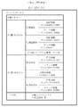
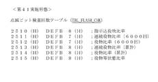
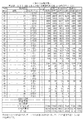
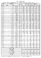
管理情報表示LED(「役比モニタ」又は「比率表示器」ともいう。)74は、たとえば後述する図31(B)に示すように4個のLEDからなり、2桁の識別セグ(下記5項目のうちのいずれの項目であるかを所定の記号等によって表示するLED)と、2桁の比率セグ(算出された比率を表示するためのLED)とから構成されている。 The management information display LED (also referred to as “role ratio monitor” or “ratio display”) 74 is composed of four LEDs, for example, as shown in FIG. 31 (B) described later, and is a two-digit identification segment (5 below). It is composed of an LED that indicates which of the items it is by a predetermined symbol or the like) and a two-digit ratio segment (LED for displaying the calculated ratio).
管理情報表示LED74は、以下の1)〜5)の5項目の比率を、所定時間ごとに繰り返して表示する。
1)有利区間比率(累計)(7U.)、又は指示込役物比率(累計)(7P.)のいずれか
2)連続役物比率(6000遊技)(6y.)
3)役物比率(6000遊技)(7y.)
4)連続役物比率(累計)(6A.)
5)役物比率(累計)(7A.)
The management
1) Advantageous section ratio (cumulative) (7U.) Or instruction-included accessory ratio (cumulative) (7P.) 2) Continuous accessory ratio (6000 games) (6y.)
3) Character ratio (6000 games) (7y.)
4) Continuous character ratio (cumulative) (6A.)
5) Character ratio (cumulative) (7A.)
たとえば、役物比率(累計)を表示する場合において、その比率が「50」%であるときは、役物比率(累計)を示す記号「7A.」を識別セグに表示し、「50」を比率セグに表示する。
ここで、「累計」とは、それまでにカウントし続けた数値の総和を指し、本実施形態では、少なくとも「175000」遊技回数以上になるまではカウントする。そして、累計が「175000」遊技回数に満たないものであるときは、たとえば点滅表示によって比率を表示し、「175000」遊技回数以上であるときは、たとえば点灯表示によって比率を表示する。累計は、「175000」遊技回数以上となった後も、RWM53の所定アドレスに記憶可能な値(上限値)に到達するまで加算し続ける。
また、「6000遊技」とは、1セットを「400」遊技回数とし、その15セットを合計した遊技回数である。
For example, in the case of displaying the character ratio (cumulative), when the ratio is "50"%, the symbol "7A." Indicating the character ratio (cumulative) is displayed in the identification segment, and "50" is displayed. Display in the ratio segment.
Here, the "cumulative" refers to the sum of the numerical values that have been continuously counted up to that point, and in the present embodiment, the numbers are counted until at least the number of "175000" games is reached. When the cumulative total is less than the number of "175000" games, the ratio is displayed by, for example, a blinking display, and when the total number of games is "175000" or more, the ratio is displayed by, for example, a lighting display. The cumulative total continues to be added until the value (upper limit value) that can be stored in the predetermined address of the
Further, "6000 games" is the total number of games in which one set is "400" and the 15 sets are totaled.
「有利区間比率」とは、全遊技区間(非有利区間+有利区間)に対して、有利区間に滞在していた比率(割合)を指す。具体的には、たとえば全遊技区間の遊技回数が「1000」で、その間の有利区間の遊技回数が「700」であるときは、有利区間比率は、「70%」となる。
また、「指示込役物比率」とは、役物作動時の払出し数と、指示機能を作動させた遊技での払出し数との合計を、総払出し数で割った値である。なお、役物を搭載していないスロットマシンでは、「指示込役物比率」は、指示機能を作動させた遊技での払出し数を総払出し数で割った値となる。
役物作動時の払出し数と、指示機能を作動させた遊技での払出し数の総和は、指示込役物カウンタによってカウントされる。
The "advantageous section ratio" refers to the ratio (ratio) of staying in the advantageous section with respect to all the gaming sections (non-advantageous section + advantageous section). Specifically, for example, when the number of games played in all the game sections is "1000" and the number of games played in the advantageous section during that period is "700", the advantageous section ratio is "70%".
Further, the "instructed bonus ratio" is a value obtained by dividing the total of the number of payouts when the bonus is activated and the number of payouts in the game in which the instruction function is activated by the total number of payouts. In a slot machine not equipped with an accessory, the "instruction-included accessory ratio" is a value obtained by dividing the number of payouts in the game in which the instruction function is activated by the total number of payouts.
The sum of the number of payouts when the accessory is activated and the number of payouts in the game in which the instruction function is activated is counted by the instruction-included accessory counter.
さらにまた、「指示機能を作動させた遊技での払出し数」は、指示機能の作動により表示された押し順に従ってストップスイッチ42を操作したことに基づいて、たとえば後述する図58中、当選番号「3」〜「8」の10枚ベルが入賞したときは、指示込役物カウンタに「10」が加算される。
これに対し、指示機能を作動させた遊技において、表示された押し順と異なる押し順でストップスイッチ42を操作したために、図58の例における1枚ベルが入賞したときは、指示込役物カウンタに「1」が加算される。
同様に、指示機能を作動させた遊技において、表示された押し順と異なる押し順でストップスイッチ42を操作したために、当選役を取りこぼしたとき(役の非入賞時)は、指示込役物カウンタには加算されない。換言すれば、前回遊技でのカウント値のままとなる。
Furthermore, the "number of payouts in the game in which the instruction function is activated" is based on the fact that the
On the other hand, in the game in which the instruction function is activated, when the
Similarly, in a game in which the instruction function is activated, when the winning combination is missed (when the combination is not won) because the
なお、後述する図26の例において、AT中に共通ベル(当選番号「3」)に当選したときは、押し順ベルに当選したときと同様に指示機能を作動させ、獲得数表示LED78に押し順指示情報(ダミー)を表示する場合と、指示機能を作動させない場合とが挙げられる。そして、共通ベルの当選時に指示機能を作動させた場合には、当該遊技での払出し数は、指示込役物カウンタに加算される。
In the example of FIG. 26, which will be described later, when the common bell (winning number “3”) is won during AT, the instruction function is activated in the same manner as when the push order bell is won, and the winning
一方、共通ベルに当選した場合において、指示機能を作動させないときは、当該遊技の払出し数は、指示込役物カウンタに加算されない。ただし、総払出数しカウンタには加算される。この場合、サブ制御基板80により、画像又は音声により正解押し順を報知する場合も含まれる。
On the other hand, when the common bell is won and the instruction function is not activated, the payout number of the game is not added to the instruction-included accessory counter. However, the total number of payouts is added to the counter. In this case, the case where the
「連続役物比率」とは、総払出し数に対する、第一種特別役物(RB)の作動時における払出し数の比率を指す。したがって、本実施形態では、「総払い出し数に対する、1BB作動中の払出し数」を指す。
たとえば、「6000」遊技回数における総払出し数が「2000枚」で、そのうち、「第一種特別役物(RB)」作動時の払出し数が「500枚」であったとき、「連続役物比率(6000遊技)」は、「25(%)」となる。
The “continuous bonus ratio” refers to the ratio of the number of payouts to the total number of payouts when the first-class special bonus (RB) is in operation. Therefore, in the present embodiment, it refers to "the number of payouts during 1BB operation with respect to the total number of payouts".
For example, when the total number of payouts in the number of "6000" games is "2000", and the number of payouts when the "
また、「役物比率」とは、総払出し数に対する、役物作動時における払出し数の比率を指す。ここで、「役物」とは、上記の第一種特別役物に加えて、第二種特別役物(CB)、MB(2BBとも称される。第二種役物連続作動装置。CBが連続作動。)、SB(シングルボーナス)が含まれる。
なお、上記5項目において、その項目に該当する機能を備えていない遊技機では、比率セグを「−−」と点灯表示する。
たとえば、「RB(第1種特別役物)」を備えていない場合には、連続役物比率は存在しないので、比率表示番号「2」及び「4」の表示時には、比率セグを「−−」と点灯表示する。
以上のように、管理情報表示LED74には、5種類の比率を表示するが、後述する図29及び図30に示すように、所定の条件を満たした場合の所定のタイミングでは、テストパターンを表示する。
Further, the "role of the accessory" refers to the ratio of the number of payouts at the time of operation of the accessory to the total number of payouts. Here, the "character" is, in addition to the above-mentioned first-class special accessory, a second-class special accessory (CB) and MB (also referred to as 2BB. A second-class accessory continuous operation device. CB. Is continuous operation.), SB (single bonus) is included.
In the above five items, the ratio segment is lit and displayed as “−−” on the gaming machine that does not have the function corresponding to the item.
For example, if "RB (
As described above, the management
また、有利区間比率及び指示込役物比率は、規則上、70%以下にすべきことが定められている。また、役物比率は70%以下にすべきことが記載されており、連続役物比率は60%以下にすべきことが規定されている。
このため、管理情報表示LED74に表示された情報を見ることで、規則上の範囲内に収まっているか否かを確認することができる。
In addition, the rules stipulate that the ratio of advantageous sections and the ratio of designated accessories should be 70% or less. In addition, it is stated that the accessory ratio should be 70% or less, and it is stipulated that the continuous accessory ratio should be 60% or less.
Therefore, by looking at the information displayed on the management
なお、有利区間比率を70%以下とする仕様の遊技機を「7U」タイプと称し、指示込役物比率を70%以下とする仕様の遊技機を「7P」タイプと称する。有利区間を備える遊技機では、「7U」タイプ又は「7P」タイプのいずれかとなる。「7U」タイプの場合には、有利区間比率(累計)を管理情報表示LED74に表示し、「7P」タイプの場合には、指示込役物比率(累計)を表示する。
「7U」タイプでは、全遊技区間に対する有利区間の比率が「70」%以下にする必要があるが、「7P」タイプでは、指示機能の作動及び役物作動によって払い出された払出し数が総払出し数の70%以下にすればよく、たとえば遊技区間のうちの全期間、あるいはほとんどが有利区間であってもよい。
A gaming machine with a specification of an advantageous section ratio of 70% or less is referred to as a "7U" type, and a gaming machine with a specification of an instruction-included accessory ratio of 70% or less is referred to as a "7P" type. In a gaming machine provided with an advantageous section, it is either a "7U" type or a "7P" type. In the case of the "7U" type, the advantageous section ratio (cumulative) is displayed on the management information display LED74, and in the case of the "7P" type, the instruction-included accessory ratio (cumulative) is displayed.
In the "7U" type, the ratio of the advantageous section to the total game section needs to be "70"% or less, but in the "7P" type, the total number of payouts paid out by the operation of the instruction function and the operation of the accessory is total. It may be 70% or less of the payout number, and for example, the entire period or most of the game sections may be advantageous sections.
たとえば、非有利区間に移行したときは、100%の確率で有利区間抽選に当選するように設定すること、ほぼ100%(たとえば98%程度)の確率で有利区間抽選に当選するように設定すること、あるいは、高確率(たとえば、70%)で有利区間抽選に当選するように設定することが挙げられる。
「7U」タイプは、設定値自体を参照して指示機能に係る処理(たとえばAT抽選)を行うことはできないが、「7P」タイプは、設定値自体を参照して指示機能に係る処理を行うことが可能である。
後述する第12実施形態では、BB2内部中のほとんどが有利区間中となり、この有利区間中においてATを実行するか否かの抽選を行う。
For example, when shifting to a non-advantageous section, it is set to win the advantageous section lottery with a 100% probability, and it is set to win the advantageous section lottery with a probability of almost 100% (for example, about 98%). That, or setting to win the advantageous section lottery with a high probability (for example, 70%) can be mentioned.
The "7U" type cannot perform processing related to the instruction function by referring to the set value itself (for example, AT lottery), but the "7P" type performs processing related to the instruction function by referring to the set value itself. It is possible.
In the twelfth embodiment described later, most of the inside of the BB2 is in the advantageous section, and a lottery is performed to determine whether or not to execute the AT in the advantageous section.
また、管理情報表示LED74は、性能表示モニタとして、ぱちんこ遊技機においても適用可能である。
この場合の管理情報表示LED74(性能表示モニタ)は、スロットマシン(回胴式遊技機)の場合と同様に、2桁の識別セグと、2桁の比率セグとから構成される。そして、アウト球「60000」個ごとのリアルタイム(計測中)のベース値(「ベース値」とは、100個のアウト球に対してセーフ球が何個であるかを示す。)と、「60000」個ごとの1回前、2回前、及び3回前のベース値を順次表示する。たとえばリアルタイムのベース値の識別セグを「bL.」と表示し、1回前のベース値の識別セグを「b1.」と表示し、2回前のース値の識別セグを「b2.」と表示し、3回前のベース値の識別セグを「b3.」と表示する。
このように、管理情報表示LED74は、遊技機のうち、スロットマシンに限らず、ぱちんこ遊技機においても適用される。
Further, the management
The management information display LED 74 (performance display monitor) in this case is composed of a two-digit identification segment and a two-digit ratio segment, as in the case of the slot machine (rotary machine). Then, a real-time (measuring) base value for each "60,000" out spheres (the "base value" indicates how many safe spheres are for 100 out spheres) and "60,000". The base values of the 1st, 2nd, and 3rd times before each piece are displayed in sequence. For example, the real-time base value identification segment is displayed as "bL.", The previous base value identification segment is displayed as "b1.", And the previous base value identification segment is displayed as "b2." Is displayed, and the identification segment of the base value three times before is displayed as "b3.".
As described above, the management
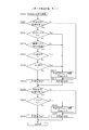
以下、図面等を参照して、本発明の一実施形態について説明する。
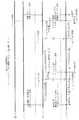
図1は、本実施形態における遊技機の一例であるスロットマシン10の制御の概略を示すブロック図である。図1は、第1実施形態〜第5実施形態に共通するブロック図である。
スロットマシン10に設けられた代表的な制御基板として、メイン制御基板50とサブ制御基板80とを備える。
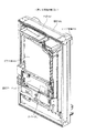
メイン制御基板50は、入力ポート51及び出力ポート52を有し、RWM53、ROM54、メインCPU55等を備える(図1で図示したもののみを備える意味ではない)。メイン制御基板50の外観や、メイン制御基板50が基板ケース56に収納されていることについては、第2実施形態(図9及び図10)で説明する。
Hereinafter, an embodiment of the present invention will be described with reference to the drawings and the like.
FIG. 1 is a block diagram showing an outline of control of a
As a typical control board provided in the
The
図1において、メイン制御基板50と、ベットスイッチ40等の操作スイッチを含む遊技進行用の周辺機器とは、入力ポート51又は出力ポート52を介して電気的に接続されている。入力ポート51は、操作スイッチ等の信号が入力される接続部であり、出力ポート52は、モータ32等の周辺機器に対して信号を送信する接続部である。
図1中、入力用の周辺機器は、その周辺機器からの信号がメイン制御基板50に向かう矢印で表示しており、出力用の周辺機器は、メイン制御基板50からその周辺機器に向かう矢印で示している(サブ制御基板80も同様である)。
In FIG. 1, the
In FIG. 1, the input peripheral device is indicated by an arrow pointing from the
RWM53は、遊技の進行等に基づいた各種データ(変数)を記憶(更新)可能な記憶媒体である。
ROM54は、遊技の進行に必要なプログラムや各種データ(たとえば、データテーブル)等を記憶しておく記憶媒体である。
メインCPU55は、メイン制御基板50上に設けられたCPU(演算機能を備えるIC)を指し、遊技の進行に必要なプログラムの実行、演算等を行い、具体的には、役の抽選、リール31の駆動制御、及び入賞時の払出し等を実行する。
The
The
The
また、メイン制御基板50上には、RWM53、ROM54、メインCPU55及びレジスタを含むMPUが搭載される。なお、RWM53及びROM54は、MPU内部に搭載されるもの以外に、外部に備えていてもよい。
なお、後述するサブ制御基板80上においても、RWM83、ROM84、及びサブCPU85を含むMPUが搭載される。なお、RWM83及びROM84は、MPU内部に搭載されるもの以外に、外部に備えてもよい。
Further, on the
The MPU including the RWM83, ROM84, and subCPU85 is also mounted on the
図1において、メダル投入口47から投入されたメダルは、メダルセレクタ内部に送られる。
なお、メダル投入口47から投入されたメダルのメダルセレクタ内での移動については、後述する図2等で説明する。
メダルセレクタ内には、図1に示すように、通路センサ46、ブロッカ45、投入センサ44(一対の投入センサ44a及び44b)が設けられており(ただし、これらに限定されるものではない)、これらは、メイン制御基板50と電気的に接続されている。
メダル投入口47から投入されたメダルは、最初に、通路センサ46に検知されるように構成されている。
In FIG. 1, the medals inserted from the
The movement of the medals inserted from the
As shown in FIG. 1, a
The medals inserted from the
さらに、通路センサ46の下流側には、ブロッカ45が設けられている。ブロッカ45は、メダルの投入を許可/不許可にするためのものであり、メダルの投入が不許可状態のときは、メダル投入口47から投入されたメダルを払出し口から返却するメダル通路を形成する。これに対し、メダルの投入が許可状態のときは、メダル投入口47から投入されたメダルをホッパー35に案内するメダル通路を形成する。ブロッカ45は、たとえば、メダルセレクタ内のメダル通路の一部に形成された開口部(メダル返却口に通じる開口部)を塞いでメダルをホッパー35側に案内するためのメダル通路を形成する切替え部材と、その切替え部材を駆動するためのアクチュエータ等とから構成されている。
Further, a
ここで、ブロッカ45は、遊技中(リール31の回転開始時から、全リール31が停止し、役の入賞時には入賞役に対応する払出しの終了時まで)は、メダルの投入を不許可状態とする。すなわち、ブロッカ45がメダルの投入を許可するのは、少なくとも遊技が行われていないときである。
Here, the
メダルセレクタ内において、ブロッカ45のさらに下流側には、投入センサ(光学センサ)44が設けられている。投入センサ44は、本実施形態では所定距離を隔てて配置された一対の投入センサ44a及び44bからなり、メダルが一方の投入センサ44aにより検知されてから所定時間を経過した後に他方の投入センサ44bにより検知されるように構成されている。そして、一対の投入センサ44がそれぞれオン/オフとなるタイミングに基づいて、正しいメダルが投入されたか否かを判断する。
In the medal selector, an insertion sensor (optical sensor) 44 is provided further downstream of the
また、図1に示すように、メイン制御基板50には、遊技者が操作する操作スイッチとして、ベットスイッチ40(40a又は40b)、スタートスイッチ41、(左、中、右)ストップスイッチ42、及び精算スイッチ43が電気的に接続されている。
ここで、「操作スイッチ(又は、単に、「スイッチ」)」とは、遊技者(操作者)による操作体の操作に基づいて(外部からの力を受け)、電気信号のオン/オフを切り替える装置(電気回路及び/又は電気部品を含む)を指し、遊技者が操作する操作体の形状を限定するものではない。
Further, as shown in FIG. 1, the
Here, the "operation switch (or simply" switch ")" switches the electric signal on / off based on the operation of the operating body by the player (operator) (receives an external force). It refers to a device (including an electric circuit and / or an electric component), and does not limit the shape of an operating body operated by a player.
操作スイッチがオフ状態であるときは、たとえば発光素子からの光が受光素子に入射し続けている(受光素子が光を検知し続けているときは、操作スイッチはオフ状態にある。)。そして、遊技者等により操作スイッチ(の操作体)が操作されると、発光素子からの光が受光素子に入射しない状態となる。この状態を検知したときに、操作スイッチがオン状態になったことを示す電気信号をメイン制御基板50に送信する。なお、上記とは逆に、操作スイッチがオフ状態であるときは発光素子からの光が受光素子に入射せず、発光素子からの光が受光素子に入射したときにオン状態となるように構成してもよい。
When the operation switch is in the off state, for example, the light from the light emitting element continues to be incident on the light receiving element (when the light receiving element continues to detect the light, the operation switch is in the off state). Then, when the operation switch (operation body) is operated by a player or the like, the light from the light emitting element is not incident on the light receiving element. When this state is detected, an electric signal indicating that the operation switch is turned on is transmitted to the
本実施形態では、スタートスイッチ41の操作体は、レバー(棒)状であり(このため、「スタートレバー(スイッチ)41」とも称される。)、ベットスイッチ40、ストップスイッチ42、及び精算スイッチ43の操作体は、押しボタン状である(このため、「ベットボタン(スイッチ)40」、「停止(ストップ)ボタン(スイッチ)42」、「精算ボタン(スイッチ)43」とも称される)。なお、後述する第4実施形態では、ストップスイッチ42の操作体(遊技者が押し込む部分)を「停止ボタン42a」と称する。
In the present embodiment, the operating body of the
また、図1では図示しないが、操作スイッチの操作体及び/又はその周囲若しくは近傍には、LED(発光手段)が設けられている。そして、その操作スイッチの操作受付けが許可状態にあるときは、たとえばその操作スイッチに対応するLED等を青色発光し、その操作スイッチの操作受付けが不許可状態にあるときは、たとえばその操作スイッチのLED等を赤色発光することにより、その操作スイッチの許可/不許可状態を遊技者に示すようにしている。 Further, although not shown in FIG. 1, an LED (light emitting means) is provided in the operating body of the operation switch and / or in the vicinity or the vicinity thereof. Then, when the operation acceptance of the operation switch is in the permitted state, for example, the LED corresponding to the operation switch emits blue light, and when the operation acceptance of the operation switch is in the disallowed state, for example, the operation switch of the operation switch By emitting red light from the LED or the like, the player is shown the permission / non-permission state of the operation switch.
具体的には、たとえば全リール31が回転中であり、ストップスイッチ42の操作が受付け可能な状態であるときは、すべてのストップスイッチ42のLEDを青色発光させ、操作可能であることを遊技者に示す。そして、1つのストップスイッチ42が操作されると、操作されたストップスイッチ42に対応するリール31が停止制御される。その後、残りのストップスイッチ42が操作可能となるのは、停止制御されたリール31に対応するモータ32の励磁状態が終了し、かつ、操作されたストップスイッチ42の検知センサ42e(後述する第4実施形態)がオフになった後である。したがって、その間は、すべてのストップスイッチ42のLEDを赤色発光する。そして、操作されたストップスイッチ42に対応するモータ32の励磁状態が終了し、かつ、そのストップスイッチ42に対応する検知センサ42eがオフになったときは、すでに操作されたストップスイッチ42のLEDは赤色発光のままであるが、未だ操作されていないストップスイッチ42のLEDについては青色発光させる。
Specifically, for example, when all the
ベットスイッチ40は、貯留されたメダルを今回遊技のためにベットするときに遊技者に操作される操作スイッチである。本実施形態では、1枚のメダルを投入するための1ベットスイッチ40aと、3枚(最大数、規定数)のメダルを投入するための3ベットスイッチ40bとを備える。
なお、これに限らず、2枚ベット用のベットスイッチを設けてもよい。
The
Not limited to this, a bet switch for two bets may be provided.
なお、規定数は、たとえば、役物非作動時/作動時に応じて予め定められている。具体的には、役物非作動時、SB作動時、1BB作動時は3枚、2BB作動時は2枚、等のように設定されている。1ベットスイッチ40aを2回操作すると2枚のメダルを投入可能であり、3回操作すると3枚のメダルを投入可能である。また、規定数が3枚であるときは、3ベットスイッチ40bを操作すれば一時に3枚のメダルを投入可能であり、規定数が2枚であるときは、3ベットスイッチ40bを操作すれば一時に2枚のメダルを投入可能である。規定数未満がすでにベットされている状態で3ベットスイッチ40bを操作すれば、ベット数が3枚となるようにベット処理が行われる。 It should be noted that the specified number is predetermined, for example, according to when the accessory is not operating / when the accessory is operating. Specifically, it is set such that when the accessory is not activated, when the SB is activated, 3 sheets are operated when 1BB is operated, 2 sheets are set when 2BB is operated, and so on. When the 1-bet switch 40a is operated twice, two medals can be inserted, and when the one-bet switch 40a is operated three times, three medals can be inserted. When the specified number is 3, the 3-bet switch 40b can be operated to insert 3 medals at a time, and when the specified number is 2, the 3-bet switch 40b can be operated. Two medals can be inserted at one time. If the 3-bet switch 40b is operated while less than the specified number has already been bet, the betting process is performed so that the number of bets is 3.
また、スタートスイッチ41は、(左、中、右のすべての)リール31を始動させるときに遊技者に操作される操作スイッチである。
さらにまた、ストップスイッチ42は、3つ(左、中、右)のリール31に対応して3つ設けられ、対応するリール31を停止させるときに遊技者に操作される操作スイッチである。
さらに、精算スイッチ43は、スロットマシン10内部にベット及び/又は貯留(クレジット)されたメダルを払い戻す(ペイアウトする)ときに遊技者に操作される操作スイッチである。
Further, the
Furthermore, the
Further, the
また、図1に示すように、メイン制御基板50には、表示基板75が電気的に接続されている。なお、実際には、メイン制御基板50と表示基板75との間には、中継基板が設けられ、メイン制御基板50と中継基板、及び中継基板と表示基板75とが接続されているが、図1では中継基板の図示を省略している。このように、メイン制御基板50と表示基板75とは、直接ハーネス等で接続されていてもよいが、両者間に別の基板が介在してもよい。
さらに、制御基板同士が直接ハーネス等で接続されていることに限らず、他の別基板(中継基板等)を介して接続されていてもよい。たとえば、メイン制御基板50とサブ制御基板80との間に1つ以上の他の別基板(中継基板等)が介在してもよい。
Further, as shown in FIG. 1, a
Further, the control boards are not limited to being directly connected by a harness or the like, and may be connected via another board (relay board or the like). For example, one or more other separate boards (relay board, etc.) may be interposed between the
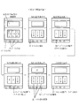
表示基板75には、クレジット数表示LED76、及び獲得数表示LED78が搭載されている。
クレジット数表示LED76は、スロットマシン10内部に貯留(クレジット)されたメダル枚数を表示するLEDであり、上位桁及び下位桁の2桁から構成されている。
The
The credit
また、獲得数表示LED78は、役の入賞時に、払出し数(遊技者の獲得数)を表示するLEDであり、クレジット数表示LED76と同様に、上位桁及び下位桁の2桁から構成されている。
なお、獲得数表示LED78は、払い出されるメダルがないときは、消灯するように制御してもよい。あるいは、上位桁を消灯し、下位桁のみを「0」表示してもよい。
Further, the acquired
The acquired
また、獲得数表示LED78は、通常は獲得数を表示するが、エラー発生時にはエラーの内容(種類)を表示するLEDとして機能する。
さらにまた、獲得数表示LED78は、AT中に押し順を報知する遊技では、押し順指示情報を表示する(有利な押し順を報知する)LEDとして機能する。よって、本実施形態における獲得数表示LED78は、獲得数、エラー内容、及び押し順指示情報の表示を兼ねるLEDである。ただし、これに限らず、押し順指示情報を表示する専用のLED等を設けてもよいのはもちろんである。
なお、AT中において、有利な押し順の報知は、サブ制御基板80に接続された画像表示装置23によっても実行される。
Further, the acquired
Furthermore, the acquired number display LED 78 functions as an LED that displays push order instruction information (notifies an advantageous push order) in a game that notifies the push order during AT. Therefore, the acquired
During AT, the advantageous push order notification is also executed by the
図1において、メイン制御基板50には、図柄表示装置のモータ(本実施形態ではステッピングモータ)32等が電気的に接続されている。
図柄表示装置は、図柄を表示する(本実施形態では3つの)リール31と、各リール31をそれぞれ駆動するモータ32と、リール31の位置を検出するためのリールセンサ33とを含む。
In FIG. 1, a motor (stepping motor in this embodiment) 32 or the like of a symbol display device is electrically connected to the
The symbol display device includes a
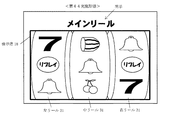
モータ32は、リール31を回転させるための駆動手段となるものであり、各リール31の回転中心部に連結され、後述するリール制御手段65によって制御される。ここで、リール31は、左リール31、中リール31、右リール31からなり、左リール31を停止させるときに操作するストップスイッチ42が左ストップスイッチ42であり、中リール31を停止させるときに操作するストップスイッチ42が中ストップスイッチ42であり、右リール31を停止させるときに操作するストップスイッチ42が右ストップスイッチ42である。
The
リール31は、リング状のものであって、その外周面には複数種類の図柄(役に対応する図柄組合せを構成している図柄)を印刷したリールテープを貼付したものである。
また、各リール31には、1個(2個以上であってもよい)のインデックスが設けられている。インデックスは、リール31のたとえば周側面に凸状に設けられており、リール31が所定位置を通過したか否かや、1回転したか否か等を検出するときに用いられる。そして、各インデックスは、リールセンサ33により検知される。リールセンサ33の信号は、メイン制御基板50に電気的に接続されている。そして、インデックスがリールセンサ33を検知する(切る)と、その入力信号がメイン制御基板50に入力され、そのリール31が所定位置を通過したことが検知される。
The
Further, each
また、リールセンサ33がリール31のインデックスを検知した瞬間の基準位置上の図柄を予めROM54に記憶している。これにより、インデックスを検知した瞬間の基準位置上の図柄を検知することができる。さらに、リールセンサ33がリール31のインデックスを検知した瞬間から、(ステッピング)モータ32を何パルス駆動すれば、前記基準位置上の図柄から数えて何図柄先の図柄を有効ライン上に停止させることができるかを識別可能となる。
Further, the symbol on the reference position at the moment when the
また、メイン制御基板50には、メダル払出し装置が電気的に接続されている。メダル払出し装置は、メダルを溜めておくためのホッパー35と、ホッパー35のメダルを払出し口から払い出すときに駆動するホッパーモータ36と、ホッパーモータ36から払い出されたメダルを検出するための払出しセンサ37を備える。
Further, a medal payout device is electrically connected to the
メダル投入口47から手入れされ、受け付けられた(正常であると判断された)メダルは、ホッパー35内に収容されるように形成されている。
払出しセンサ(光学センサ)37は、本実施形態では、所定距離を隔てて配置された一対の払出しセンサ37a及び37bからなる。そして、メダルが払い出されるときには、そのメダルにより所定の移動部材(後述する図7の可動片39a)が移動する。所定の移動部材の移動によって、払出しセンサ37a及び37bがオン/オフされる。所定時間の範囲内で払出しセンサ37a及び37bがそれぞれオン/オフされたか否かに基づいて、メダルが正しく払い出されたか否かを判断する。
The medals that have been maintained and accepted (determined to be normal) from the
In the present embodiment, the payout sensor (optical sensor) 37 includes a pair of payout sensors 37a and 37b arranged at a predetermined distance from each other. Then, when the medal is paid out, a predetermined moving member (movable piece 39a in FIG. 7, which will be described later) moves by the medal. The payout sensors 37a and 37b are turned on / off by the movement of the predetermined moving member. It is determined whether or not the medals are correctly paid out based on whether or not the payout sensors 37a and 37b are turned on / off within a predetermined time range.
たとえば、ホッパーモータ36が駆動しているにもかかわらず、一対の払出しセンサ37のオンを検知しないときは、メダルが払い出されていないと判断し、ホッパーエラー(メダルなし)と検知される。
一方、払出しセンサ37の少なくとも1つがオン信号を出力し続けたままとなったときは、メダル詰まりが生じたと検知する。
なお、これらの動作の詳細については、後述する図6〜図8で説明する。
For example, when the on of the pair of
On the other hand, when at least one of the
The details of these operations will be described with reference to FIGS. 6 to 8 described later.
遊技者は、遊技を開始するときは、ベットスイッチ40の操作により予めクレジットされたメダルを投入するか(貯留ベット)、又はメダル投入口47からメダルを手入れ投入する(手入れベット)。当該遊技の規定数のメダルがベットされた状態でスタートスイッチ41が操作されると、そのときに発生する信号がメイン制御基板50に入力される。メイン制御基板50(具体的には、後述するリール制御手段65)は、この信号を受信すると、役抽選手段61による抽選を行うとともに、すべてのモータ32を駆動制御して、すべてのリール31を回転させるように制御する。このようにしてリール31がモータ32によって回転されることで、リール31上の図柄は、所定の速度で表示窓内で上下方向に移動表示される。
When the player starts the game, he / she inserts a pre-credited medal by operating the bet switch 40 (storage bet), or takes care of the medal from the medal insertion slot 47 (maintenance bet). When the
そして、遊技者は、ストップスイッチ42を押すことで、そのストップスイッチ42に対応するリール31(たとえば、左ストップスイッチ42に対応する左リール31)の回転を停止させる。ストップスイッチ42が操作されると、そのときに発生する信号がメイン制御基板50に入力される。メイン制御基板50(具体的には、後述するリール制御手段65)は、この信号を受信すると、そのストップスイッチ42に対応するモータ32を駆動制御して、役抽選手段61の抽選結果(内部抽せん手段により決定した結果)に対応するように、そのモータ32に係るリール31の停止制御を行う。
Then, by pressing the
そして、すべてのリール31の停止時における図柄組合せにより、今回遊技の遊技結果を表示する。さらに、いずれかの役に対応する図柄組合せが有効ラインに停止したとき(その役の入賞となったとき)は、入賞した役に対応するメダルの払出し等が行われる。
Then, the game result of this game is displayed by the symbol combination when all the
次に、メイン制御基板50の具体的構成について説明する。
図1に示すように、メイン制御基板50のメインCPU55は、以下の役抽選手段61等を備える。本実施形態における以下の各手段は例示であり、本実施形態で示した手段に限定されるものではない。
Next, a specific configuration of the
As shown in FIG. 1, the
役抽選手段61は、当選番号の抽選(決定、選択)を行う。ここで、「役抽選手段61による当選番号の抽選」は、風営法規則(遊技機の認定及び型式の検定等に関する規則。以下、単に「規則」という。)における「内部抽せん」と同じであり、役抽選手段61による抽選結果は、規則における「内部抽せんにより決定した結果」と同じである。したがって、役抽選手段61を、規則に合わせた表現で、「内部抽せん手段61」とも称する。
役抽選手段61により当選番号が決定されると、その当選番号に基づいて、入賞及びリプレイ条件装置番号、並びに役物条件装置番号が決定され、当該遊技で作動可能となる入賞及びリプレイ条件装置、並びに役物条件装置が定まることとなる。このため、役抽選手段61は、条件装置番号の決定(抽選又は選択)手段、当選役決定(抽選又は選択)手段等とも称される。
The winning combination lottery means 61 draws (determines, selects) the winning number. Here, the "lottery of the winning number by the role lottery means 61" is the same as the "internal lottery" in the Fukuei Law Regulations (rules concerning certification of gaming machines and type verification, etc., hereinafter simply referred to as "rules"). The lottery result by the combination lottery means 61 is the same as the "result determined by the internal lottery" in the rules. Therefore, the winning combination lottery means 61 is also referred to as an "internal lottery means 61" in terms of rules.
When the winning number is determined by the winning combination lottery means 61, the winning and replay condition device number and the accessory condition device number are determined based on the winning number, and the winning and replay condition device that can be operated in the game is determined. In addition, the accessory condition device will be determined. Therefore, the winning combination lottery means 61 is also referred to as a condition device number determination (lottery or selection) means, a winning combination determination (lottery or selection) means, and the like.
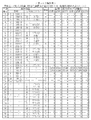
役抽選手段61は、たとえば、抽選用の乱数発生手段(ハードウェア乱数等)と、この乱数発生手段が発生する乱数を抽出する乱数抽出手段と、乱数抽出手段が抽出した乱数値に基づいて、当選番号を決定する当選番号決定手段とを備えている。 The combination lottery means 61 is based on, for example, a random number generating means (hardware random number or the like) for lottery, a random number extracting means for extracting random numbers generated by the random number generating means, and a random number value extracted by the random number extracting means. It is equipped with a winning number determining means for determining the winning number.
乱数発生手段は、所定の領域(たとえば10進数で「0」〜「65535」)の乱数を発生させる。乱数は、たとえば200n(ナノ)secで1カウントを行うカウンターが「0」〜「65535」の範囲を1サイクルとしてカウントし続ける乱数であり、スロットマシン10の電源が投入されている間は、乱数をカウントし続ける。
The random number generation means generates random numbers in a predetermined region (for example, "0" to "65535" in decimal). The random number is, for example, a random number that the counter that counts 1 in 200 n (nano) sec keeps counting in the range of "0" to "65535" as one cycle, and is a random number while the power of the
乱数抽出手段は、乱数発生手段によって発生した乱数を、所定の時、本実施形態では遊技者によりスタートスイッチ41が操作(オン)された時に抽出する。判定手段は、乱数抽出手段により抽出された乱数値を、後述する抽選テーブルと照合することにより、その乱数値が属する領域に対応する当選番号を決定する。
The random number extraction means extracts the random numbers generated by the random number generation means at a predetermined time, in the present embodiment, when the
当選フラグ制御手段62は、役抽選手段61による抽選結果に基づいて、各役に対応する当選フラグのオン/オフを制御するものである。本実施形態では、すべての役について、役ごとに当選フラグを備える。そして、役抽選手段61による抽選においていずれかの役の当選となったときは、その役の当選フラグをオンにする(当選フラグを立てる)。なお、役の当選には、当選役が1つである場合(単独当選)と、当選役が複数ある場合(重複当選)とが挙げられる。 The winning flag control means 62 controls on / off of the winning flag corresponding to each winning combination based on the lottery result by the winning combination lottery means 61. In the present embodiment, a winning flag is provided for each combination for all the combinations. Then, when any of the winning combinations is won in the lottery by the winning combination lottery means 61, the winning flag of that winning combination is turned on (the winning flag is set). The winning combination may be a case where there is one winning combination (single winning) or a case where there are a plurality of winning combinations (duplicate winning).
押し順指示番号選択手段63は、役抽選手段61による当選番号の抽選結果(押し順ベル、又は押し順リプレイ当選時)に基づいて、押し順指示番号(正解押し順に相当する番号)の選択(決定)を行うものである。
ここで選択される押し順指示番号の「押し順」とは、遊技者にとって有利な押し順(正解押し順)を意味する。たとえば押し順ベルの当選時には、高目ベルを入賞させる押し順(正解押し順)を指す。また、リプレイ重複当選時は、有利なRTに昇格させる押し順又は不利なRTに転落させない押し順を指す。
The push order instruction number selection means 63 selects the push order instruction number (the number corresponding to the correct push order) based on the lottery result (push order bell or push order replay winning) of the winning number by the winning combination lottery means 61 (the number corresponding to the correct push order). It is to make a decision).
The "push order" of the push order instruction number selected here means a push order (correct push order) that is advantageous to the player. For example, when the push order bell is won, it refers to the push order (correct push order) in which the higher bell is won. In addition, when a replay duplicate is won, it refers to a push order that promotes to an advantageous RT or a push order that does not cause a fall to an unfavorable RT.
本実施形態では、当選番号ごとに、それぞれ固有の押し順指示番号を備える。
そして、AT中に、押し順ベル又は押し順リプレイに当選したときは、メイン制御基板50は、上述した獲得数表示LED78に、押し順指示番号に対応する押し順指示情報、具体的には「=*」(「*」=1、2、・・)のような情報を表示する。このように、有利な押し順を有する条件装置の作動時に、押し順指示情報を表示する機能は、指示機能とも称される。
また、AT中に、押し順ベル又は押し順リプレイに当選したときは、メイン制御基板50は、遊技の開始時(スタートスイッチ41が操作され、当選番号が決定された後)に、サブ制御基板80に対し、押し順指示番号に対応するコマンドを送信する。
サブ制御基板80は、当該コマンドを受信したときは、正解押し順を画像表示装置23で画像表示する。
In the present embodiment, each winning number is provided with a unique push order instruction number.
Then, when the push order bell or the push order replay is won during AT, the
Further, when the push order bell or the push order replay is won during AT, the
When the
なお、メイン制御基板50が選択した押し順指示番号をサブ制御基板80に送信することができるのは、有利区間(AT)中に限られる。したがって、通常区間において押し順指示番号選択手段63により押し順指示番号が選択されたとしても、その押し順指示番号がサブ制御基板80に送信されることはない。なお、通常区間では、押し順指示番号を選択しなくてもよい。
The push order instruction number selected by the
演出グループ番号選択手段64は、当選番号に対応する演出グループ番号であって、サブ制御基板80に送信するための番号を選択するものである。
ここで、当選番号に対応する演出グループ番号が予め定められている。そして、演出グループ番号選択手段64は、スタートスイッチ41が操作されることにより当選番号が決定すると、当該遊技の当選番号に対応する演出グループ番号を選択し、メイン制御基板50は、選択した演出グループ番号をサブ制御基板80に送信する。サブ制御基板80は、受信した演出グループ番号に基づいて、当選役に関する演出を出力する。演出グループ番号は、上記の押し順指示番号と異なり、毎遊技選択され、メイン制御基板50からサブ制御基板80に送信される。
The effect group number selection means 64 is an effect group number corresponding to the winning number, and selects a number to be transmitted to the
Here, the production group number corresponding to the winning number is predetermined. Then, when the winning number is determined by operating the
また、メイン制御基板50は、サブ制御基板80に対し、当該遊技の当選番号を送信しない。このため、サブ制御基板80は、当該遊技の当選番号を知ることはできない。ただし、サブ制御基板80は、毎遊技、演出ブループ番号を受信するので、受信した演出グループ番号に基づいて、演出を出力可能となる。ただし、押し順ベル又は押し順リプレイの当選時であっても、演出グループ番号から正解押し順を判断できないので、サブ制御基板80は、演出グループ番号に基づいて正解押し順を報知することはない。これに対し、AT中は、押し順ベル又は押し順リプレイの当選時は、メイン制御基板50からサブ制御基板80に対し、押し順指示番号を送信する。これにより、サブ制御基板80は、受信した押し順指示番号に基づいて、正解押し順を報知可能となる。
Further, the
リール制御手段65は、リール31の回転開始命令を受けたとき、特に本実施形態ではスタートスイッチ41の操作を検知したときに、すべて(3つ)のリール31の回転を開始するように制御する。
さらに、リール制御手段65は、役抽選手段61により当選番号の決定が行われた後、今回遊技における当選フラグのオン/オフを参照して、当選フラグのオン/オフに対応する停止位置決定テーブルを選択するとともに、ストップスイッチ42が操作されたときに、ストップスイッチ42の操作を検知したときのタイミングに基づいて、そのストップスイッチ42に対応するリール31の停止位置を決定するとともに、モータ32を駆動制御して、その決定した位置にそのリール31を停止させるように制御する。
The reel control means 65 controls to start the rotation of all (three)
Further, the reel control means 65 refers to the on / off of the winning flag in this game after the winning number is determined by the winning combination lottery means 61, and the stop position determination table corresponding to the on / off of the winning flag. Is selected, and when the
たとえば、リール制御手段65は、少なくとも1つの当選フラグがオンである遊技では、リール31の停止制御の範囲内において、当選役(当選フラグがオンになっている役)に対応する図柄組合せを有効ラインに停止可能にリール31を停止制御するとともに、当選役以外の役(当選フラグがオフになっている役)に対応する図柄組合せを有効ラインに停止させないようにリール31を停止制御する。
For example, the reel control means 65 enables a symbol combination corresponding to a winning combination (a combination in which the winning flag is turned on) within the range of stop control of the
ここで、「リール31の停止制御の範囲内」とは、ストップスイッチ42が操作された瞬間からリール31が実際に停止するまでの時間又はリール31の回転量(移動図柄(コマ)数)の範囲内を意味する。
本実施形態では、リール31は、定速時は1分間で約80回転する速度で回転される。
そして、ストップスイッチ42が操作されたときは、MB作動中の所定のリール31(たとえば、中リール31)を除き、ストップスイッチ42が操作された瞬間からリール31を停止させるまでの時間が190ms以内に設定されている。これにより、本実施形態では、MB作動中の所定のリール31を除き、ストップスイッチ42が操作された瞬間の図柄からリール31が停止するまでの最大移動図柄数が4図柄に設定されている。
Here, "within the range of stop control of the
In the present embodiment, the
When the
一方、MB作動中の所定のリール31については、ストップスイッチ42が操作された瞬間からリール31を停止させるまでの時間が75ms以内に設定されている。これにより、MB作動中の所定のリール31については、ストップスイッチ42が操作された瞬間の図柄からリール31が停止するまでの最大移動図柄数が1図柄に設定されている。
On the other hand, for the
そして、ストップスイッチ42の操作を検知した瞬間に、リール31の停止制御の範囲内にある図柄のいずれかが所定の有効ラインに停止させるべき図柄であるときは、ストップスイッチ42が操作されたときに、その図柄が所定の有効ラインに停止するように制御される。
すなわち、ストップスイッチ42が操作された瞬間に直ちにリール31を停止させると、当選番号に対応する役の図柄が所定の有効ラインに停止しないときには、リール31を停止させるまでの間に、リール31の停止制御の範囲内においてリール31を回転移動制御することで、当選番号に対応する役の図柄をできる限り所定の有効ラインに停止させるように制御する(引込み停止制御)。
Then, at the moment when the operation of the
That is, if the
また逆に、ストップスイッチ42が操作された瞬間に直ちにリール31を停止させると、当選番号に対応しない役の図柄組合せが有効ラインに停止してしまうときは、リール31の停止時に、リール31の停止制御の範囲内においてリール31を回転移動制御することで、当選番号に対応しない役の図柄組合せを有効ラインに停止させないように制御する(蹴飛ばし停止制御)。
さらに、複数の役に当選している遊技(たとえば、押し順ベル当選時)では、ストップスイッチ42の押し順や、ストップスイッチ42の操作タイミングに応じて、入賞させる役の優先順位が予め定められており、所定の優先順位によって、最も優先する役に係る図柄の引込み停止制御を行う。
On the contrary, if the
Further, in a game in which a plurality of roles are won (for example, when the push order bell is won), the priority of the winning combination is predetermined according to the pressing order of the
入賞判定手段66は、リール31の停止時に、有効ラインに停止したリール31の図柄組合せが、いずれかの役に対応する図柄組合せであるか否かを判断するものである。
ここで、入賞判定手段66は、実際に、役に対応する図柄組合せが有効ラインに停止したか否かを検知することはない。具体的には、当該遊技で作動した条件装置と、ストップスイッチ42の押し順及び/又はストップスイッチ42の操作タイミングとから、リール31が実際に停止する前に有効ラインに停止する図柄組合せを予め判断するか、又はリール31の停止後に有効ラインに停止した図柄組合せを予め判断する。
The winning determination means 66 determines whether or not the symbol combination of the
Here, the winning determination means 66 does not actually detect whether or not the symbol combination corresponding to the winning combination has stopped at the effective line. Specifically, from the condition device operated in the game and the pressing order of the
制御コマンド送信手段71は、サブ制御基板80に対し、サブ制御基板80で出力する演出に必要な情報(制御コマンド)を送信する。
制御コマンドとしては、たとえばベットスイッチ40が操作されたときの情報、スタートスイッチ41が操作されたときの情報、押し順指示番号(AT中、かつ正解押し順を有する当選番号に当選したときのみ)、演出グループ番号、RT(遊技状態)情報、ストップスイッチ42が操作されたときの情報、入賞した役の情報等が挙げられる。
The control command transmitting means 71 transmits information (control command) necessary for the effect output by the
The control commands include, for example, information when the
図1において、サブ制御基板80は、遊技中及び遊技待機中における演出(情報)の選択や出力等を制御するものである。
ここで、メイン制御基板50とサブ制御基板80とは、電気的に接続されており、メイン制御基板50(制御コマンド送信手段71)は、パラレル通信によってサブ制御基板80に一方向で、演出の出力に必要な情報(制御コマンド)を送信する。
なお、メイン制御基板50とサブ制御基板80とは、電気的に接続されることに限らず、光通信手段を用いた接続であってもよい。さらに、電気的接続及び光通信接続のいずれも、パラレル通信に限らず、シリアル通信であってもよく、シリアル通信とパラレル通信とを併用してもよい。
In FIG. 1, the
Here, the
The
サブ制御基板80は、メイン制御基板50と同様に、入力ポート81、出力ポート82、RWM83、ROM84、及びサブCPU85等を備える。
サブ制御基板80には、入力ポート81又は出力ポート82を介して、図1に示すような以下の演出ランプ21等の演出用周辺機器が電気的に接続されている。ただし、演出用の周辺機器は、これらに限られるものではない。
RWM83は、サブCPU85が演出を制御するときに取り込んだデータ等を一時的に記憶可能な記憶媒体である。
また、ROM84は、演出用データとして、演出に係る抽選を行うとき等のプログラムや各種データ等を記憶しておく記憶媒体である。
Like the
The following peripheral devices for effect such as the
The
Further, the
演出ランプ21は、たとえばLED等からなり、所定の条件を満たしたときに、それぞれ所定のパターンで点灯する。なお、演出ランプ21には、各リール31の内周側に配置され、リール31に表示された図柄(表示窓から見える上下に連続する3図柄)を背後から照らすためのバックランプ、リール31の上部からリール31上の図柄を照光する蛍光灯、スロットマシン10のフロントドア前面に配置され、役の入賞時等に点滅する枠ランプ等が含まれる。
The
また、スピーカ22は、遊技中に各種の演出を行うべく、所定の条件を満たしたときに、所定のサウンドを出力するものである。
さらにまた、画像表示装置23は、液晶ディスプレイ、有機ELディスプレイ、ドットディスプレイ等からなるものであり、遊技中に各種の演出画像(正解押し順、当該遊技で作動する条件装置に対応する演出等)や、遊技情報(役物作動時や有利区間(AT)中の遊技回数や獲得枚数等)等を表示するものである。
Further, the
Furthermore, the
図2は、メダル投入口47から投入されたメダルMが投入センサ44a及び44bを通過するまでの様子を示す図であって、正面から見た模式図である。図2では、メダルセレクタの内部が見えるように図示している。また、メダルMは、その位置に応じて、M1〜M4を示している。M1の位置は、メダルMがメダル投入口47のメダル置き部47bに置かれている状態(放たれる前の状態)を示す。すなわち、M1の位置では、正面から見て、メダルMの外周縁の最下点とメダル置き部47bの上面とが当接している。
なお、図2(及び後述する図4)において、投入センサ44a及び44bとして表示した略正方形の部分全体が、それぞれ投入センサ44a及び44bの受発光範囲(センサの目)であるものとする(それぞれ投入センサ44a及び44bの筐体ではない。)。
FIG. 2 is a diagram showing a state in which the medal M inserted from the
In addition, in FIG. 2 (and FIG. 4 described later), it is assumed that the entire substantially square portion displayed as the
また、M2の位置は、正面から見てメダルMが見えなくなった瞬間の位置を示している。すなわち、M2の位置では、メダルMの外周縁の最上点とメダル置き部47bの上面とが重なる位置である。たとえば、メダルMがM1の位置にあるときに遊技者がメダルMから手を離すと仮定すると、メダルMは、M1の位置から落下する。したがって、M2の位置では、遊技者の手から放れている状態であって下流側に落下(移動)している状態である。
なお、「上流側」とはメダル投入口47側を示し、「下流側」とは投入センサ44b側(ホッパー35側)を指すものとする。メダルMの位置でいえば、上流側から下流側に向かって、M1→M2→M3→M4となる。
Further, the position of M2 indicates the position at the moment when the medal M disappears when viewed from the front. That is, at the position of M2, the uppermost point of the outer peripheral edge of the medal M and the upper surface of the medal placing portion 47b overlap. For example, assuming that the player releases the medal M when the medal M is in the position of M1, the medal M falls from the position of M1. Therefore, at the position of M2, it is in a state of being released from the player's hand and falling (moving) to the downstream side.
The "upstream side" refers to the
図2の例では、メダルMがM2に位置しているときには、通路センサ46によってメダルMが検知されるように通路センサ46を配置している。
さらに、M3の位置は、投入センサ44aによってメダルMが検知された瞬間(オン)の位置を示す。また、M4の位置は、投入センサ44bによってメダルMが検知されなくなった瞬間(オフ)の位置を示している。
In the example of FIG. 2, when the medal M is located at M2, the
Further, the position of M3 indicates the position at the moment (on) when the medal M is detected by the
メダル投入口47は、遊技者が遊技媒体としてのメダルMをベット又はクレジットするときに、メダルMをスロットマシン10内部(メダルセレクタ)に投入する部分である。メダル投入口47は、メダルガード部47aと、メダル置き部47bとを備える。メダル置き部47bは、複数枚(最大で10枚程度)の重ねたメダルMを同時に載置可能に、図面の紙面に対して垂直方向に伸びる略湾曲面(メダルMの周縁よりもやや大きな曲率を有する曲面)を有する。
The
メダル置き部47bの前記略湾曲面と、メダルガード部47aのメダルMが接触する面(図2で見えている面)は、略垂直に交差するように形成されている。
さらに、図2では表れていないが、メダル置き部47bとメダルガード部47aとが交差する部分には、1枚のメダルMを流下可能な開口部を有している。2枚のメダルMを重ねた状態では前記開口部からメダルMが落下しないが、1枚のメダルMの厚みのときは前記開口部からメダルMが流下するように形成されている。このため、遊技者は、たとえば重ねた複数枚のメダルMをメダル置き部47b上に載置し、その複数枚のメダルMをメダルガード部47aの方向に押し当てつつ、押し当て力を強めたり弱めたりすることで、メダル置き部47b上に載置したメダルMを1枚ずつ前記開口部からメダルセレクタ内に落とし込むことが可能となっている。
The substantially curved surface of the medal placing portion 47b and the surface of the medal guard portion 47a where the medal M contacts (the surface visible in FIG. 2) are formed so as to intersect substantially vertically.
Further, although not shown in FIG. 2, the portion where the medal placing portion 47b and the medal guard portion 47a intersect has an opening through which one medal M can flow down. When two medals M are stacked, the medals M do not fall from the opening, but when the thickness of one medal M is thick, the medals M are formed so as to flow down from the opening. Therefore, for example, the player places a plurality of stacked medals M on the medal holder portion 47b, and while pressing the plurality of medals M in the direction of the medal guard portion 47a, the pressing force is strengthened. By weakening the medals, the medals M placed on the medal holder 47b can be dropped one by one into the medal selector from the opening.
メダル投入口47からメダルMが投入される(下方に放たれる)と、そのメダルMは、メダルセレクタ内の通路を流下する。メダルセレクタ内には、上流側から、通路センサ46、投入センサ44a、投入センサ44bが設けられている。さらに、通路センサ46と、投入センサ44aとの間(図2では、投入センサ44aの下側)には、上述したブロッカ45が設けられている。
When the medal M is inserted (released downward) from the
メダルMがメダルセレクタ内に入ると、最初に、通路センサ46によって検知される。通路センサ46は、メダル詰まりやゴト行為の有無判断するため等に設けられたセンサであり、通路センサ46がメダルMを検知した時から、(予め定めた)所定時間、メダルMを検知し、さらに所定時間の経過後はメダルMを検知しなくなったときは、正常であると判断する。これに対し、通路センサ46がメダルを検知した後、所定時間を経過してもメダルMを検知し続けているときは、メダル滞留エラーと判断する。また、通路センサ46がメダルMを検知した後、所定時間を経過する前にメダルMを検知しなくなったときは、メダルMの不正通過であると判断する。
When the medal M enters the medal selector, it is first detected by the
メダルMがメダル通路内を流下すると、ブロッカ45の位置に到達する。ブロッカ45は、メダル通路において下面側に配置されている。ブロッカ45は、オン状態(出力ポート52のうち、ブロッカ45に係る出力ポートがオン)であるときは、メダルMが投入センサ44a及び44bによって検知可能となるようにメダル流路を形成する。換言すれば、上流側から移動してきたメダルMを、メダル通路外に送出することなく、投入センサ44a及び44b側に送る役目を持っている。
When the medal M flows down the medal passage, it reaches the position of the
これに対し、オフ状態(出力ポート52のうち、ブロッカ45に係る出力ポートがオフ)であるときは、ブロッカ45は、図2中、図面の紙面に対して垂直方向にずれるように移動することにより、メダル通路に開口部(落とし穴)を形成する。これにより、ブロッカ45がオフ状態では、メダルMは、M3に到達する直前に、この開口部から落下し、メダル通路外に送られる(図2中、M5)。この開口部から落下したメダルMは、投入センサ44aに検知されることなく、メダル返却口(図示せず)に戻される。
On the other hand, when the
たとえば、当該遊技の規定数がすでにベットされており、かつクレジット数が上限値に到達しているときは、それ以上のメダルのベット及びクレジットができないので、ブロッカ45はオフ状態に制御される。これにより、その状態においてメダルMがメダル投入口47から投入されても、前記開口部から落下してメダル返却口に戻される。
これに対し、ブロッカ45がオン状態であるときは、前記開口部がブロッカ45によって塞がれているので、メダル通路内を流下するメダルMは、ブロッカ45上を通過し、投入センサ44a及び44b側に移動可能となる。
For example, when the specified number of the game has already been bet and the number of credits has reached the upper limit, no more medals can be bet or credits, so the
On the other hand, when the
なお、本実施形態では、図2のようにブロッカ45を配置したが、この配置に限られるものではない。ブロッカ45のオン状態/オフ状態にかかわらず、通路センサ46によってメダルMを検知することができ、ブロッカ45がオン状態であるときはメダルMを投入センサ44a及び44bに案内することができ、かつ、ブロッカ45がオフ状態であるときはメダルMが投入センサ44a及び44bに検知されることなくメダル返却口に送ることができればよい。換言すれば、通路センサ46と投入センサ44aとの間にブロッカ45が位置すればよい。
In the present embodiment, the
また、通路センサ46は、ブロッカ45よりも上流側に位置していればよく、ブロッカ45がオフ状態であっても、メダル投入口47から投入されたメダルMを検知可能な位置に配置されていればよい。また、図2では、通路センサ46は、メダルMがM2に位置したときは、メダルMを検知できるように配置しているが、これに限らず、メダルMがM2の位置よりもさらに下流側に移動したときにメダルMを検知するように通路センサ46を配置することも可能である。
Further, the
投入センサ44a及び44bは、ブロッカ45を通過したメダルMを検知するためのセンサであり、これら2つのセンサは、所定距離を隔てて設置されている。まず、メダルMがM3の位置に到達したときは、上流側の投入センサ44aがメダルMを検知可能となる(オフからオンになる)。さらにメダルMが流下すると、次に投入センサ44bがメダルMを検知する(オフからオンになる)。これら2つの投入センサ44a及び44bのオン/オフのタイミングを判断することにより、投入されたメダルMが正常であるか否かを判断する。メダルMがM4の位置に到達すると、投入センサ44a及び44bに検知されなくなる。投入センサ44a及び44bを通過したメダルMは、ホッパー35に送られる。
The throw-in
図2において、メダルセレクタは、以下のように設計されている。
まず、メダルMがM2の位置、すなわちメダルセレクタを正面から見たときに、メダルMが視認不可能となった瞬間から、メダルMがM4の位置、すなわち投入センサ44bに検知されなくなる瞬間の位置に到達するまで(図2中、点線で移動軌跡を示す。)の時間を、時間T2に設定している。なお、メダルMがM1に位置しているときにそのメダルMから(初速度「0」で)手を離し、下方に放った場合の値である。よって、メダルMがM2に位置するときの速度は、「0」を超える。
In FIG. 2, the medal selector is designed as follows.
First, the position of the medal M, that is, the position of the medal M from the moment when the medal M becomes invisible when the medal selector is viewed from the front, that is, the position of the moment when the medal M is not detected by the
また、メダルMの加速度は、M2の位置からさらに下方に移動するに従って大きくなる。一方、図2中、メダル通路が垂直方向から水平方向に曲がった部分には、衝撃部材(図2では図示せず)が設けられている。この衝撃部材にメダルMが接触すると、メダルMの速度が減速されて、投入センサ44a及び44bに向かうようになっている。
そして、メダルMがM3に位置する瞬間(投入センサ44aに検知された瞬間)から、M4に位置する瞬間(投入センサ44bに検知されなくなった瞬間)までの時間を、時間T3に設定している。
Further, the acceleration of the medal M increases as it moves further downward from the position of M2. On the other hand, in FIG. 2, an impact member (not shown in FIG. 2) is provided at a portion where the medal passage is bent from the vertical direction to the horizontal direction. When the medal M comes into contact with the impact member, the speed of the medal M is decelerated so as to move toward the
Then, the time from the moment when the medal M is located at M3 (the moment when it is detected by the
<第1実施形態(A)>
図3は、本実施形態のうち、第1実施形態(A)を説明するためのタイムチャートを示す図である。
図3は、スロットマシン10の電源がオフにされたとき(たとえば、電源スイッチ11がオフにされたときや、停電が発生したとき)の電圧レベルを示すものである。
図3において、電源が正常にオン状態になっているときの電圧を供給レベルV0とする。供給レベルV0の状態では、スロットマシン10は、正常に作動する。
<First Embodiment (A)>
FIG. 3 is a diagram showing a time chart for explaining the first embodiment (A) of the present embodiment.
FIG. 3 shows the voltage level when the power of the
In FIG. 3, the voltage when the power supply is normally turned on is defined as the supply level V0. At the supply level V0, the
図3では、時刻S11のときに、電源断が発生した(電源の供給が遮断される事象が発生した)例を示している。本実施形態では、電源断が発生すると、時間T0で、電圧が電源断検知レベルV1まで低下する。
電源断が発生したとき(時刻S11;供給レベルV0)から、電源断を検知するまで(時刻S12;電源断検知レベルV1)までの時間T0は、少なくとも20割込み(1割込み時間2.235ms×20割込み=44.7ms)以上となるように設計されている。
メイン制御基板50上には、(図示しない)電圧監視装置(電源断検出回路)が設けられている。そして、電源電圧が所定値である電源断検知レベルV1以下になったときには、入力ポート51における所定のビットに電源断検知信号が入力され、その信号の入力があったか否かを検知することにより電源断を検知する。
FIG. 3 shows an example in which the power supply is cut off (an event in which the power supply is cut off occurs) at the time S11. In the present embodiment, when a power failure occurs, the voltage drops to the power failure detection level V1 at time T0.
The time T0 from when the power failure occurs (time S11; supply level V0) to when the power failure is detected (time S12; power failure detection level V1) is at least 20 interrupts (1 interrupt time 2.235 ms × 20). It is designed to have an interrupt (interrupt = 44.7 ms) or more.
A voltage monitoring device (power failure detection circuit) (not shown) is provided on the
電圧が電源断検知レベルV1からさらに低下していき、メインCPU55の駆動電圧限界V2未満になると、メインCPU55を駆動することができなくなる(メインCPU55の動作を保証できなくなる)。
図3の例では、時刻S13で、電圧レベルがメインCPU55の駆動電圧限界V2となり、その後、Lowに低下する例を示している。メイン制御基板50は、電圧が駆動電圧限界V2未満になると電源断処理を実行することができないので、電源断が時刻S11で発生したときは、少なくとも時刻S13までに、電源断処理を終了できるように設定している。
When the voltage further drops from the power failure detection level V1 and becomes less than the drive voltage limit V2 of the
In the example of FIG. 3, at time S13, the voltage level reaches the drive voltage limit V2 of the
また、電源断の検知は、2.235msごとに実行される割込み処理内で実行するが、2割込み連続で電源断を検知したときは、次の割込み処理で電源断処理を実行する。したがって、図3中、時刻S12は、2回連続で割込み処理で電圧が電源断検知レベルV1以下であると判断され、電源断が発生したと検知したタイミングである。そして、次の割込み処理で、電源断処理を実行する。
なお、割込み処理では、以下のような処理を実行する。まず、電源断を検知したか否かを判断し、電源断を検知したときは、(通常の割込み処理に移行せずに)電源断処理に移行する。電源断処理では、まず、出力ポート52をオフにする。出力ポート52をオフにする処理により、ブロッカ45がオフとなる。さらに、スタックポインタの保存処理、電源断処理済みフラグ(正常な電源断が行われたか否かを判断するためのフラグ)のセット処理、RWM53のチェックサムの実行処理、RWM53の書き込み禁止処理等を順次実行した後、リセット待ち状態(ループ処理状態)となる。このリセット待ち状態は、設計上、何も処理を行わない状態となっている。
したがって、図3に示すように、電源断を検知した割込み処理(時刻S12)の次の割込み処理で、電源断処理が実行され、ブロッカ45がオフにされる。
なお、電源断を検知した割込み処理の次の割込み処理で電源断処理を実行することに限らず、電源断を検知した割込み処理内で電源断処理を実行してもよい。この場合には、「T1=S12−S11」となる。
Further, the detection of the power failure is executed within the interrupt process executed every 2.235 ms, but when the power failure is detected for two consecutive interrupts, the power failure process is executed in the next interrupt process. Therefore, in FIG. 3, the time S12 is the timing at which it is determined that the voltage is equal to or lower than the power supply cutoff detection level V1 by the interrupt processing twice in succession, and it is detected that the power supply cutoff has occurred. Then, in the next interrupt process, the power cutoff process is executed.
In interrupt processing, the following processing is executed. First, it is determined whether or not a power failure is detected, and when a power failure is detected, the process shifts to the power cut process (without shifting to the normal interrupt process). In the power off processing, first, the
Therefore, as shown in FIG. 3, the power cutoff process is executed and the
It should be noted that the power cutoff process is not limited to the execution of the power cutoff process in the interrupt process following the interrupt process in which the power failure is detected, and the power supply cutoff process may be executed in the interrupt process in which the power failure is detected. In this case, "T1 = S12-S11".
一方、図3では、メダルが投入された後のメダル位置(M2、M4)を併せて図示している。図2において、メダルMがM1の位置にある状態で、遊技者がメダルMから手を離したと仮定する。なお、この場合には、メダルMは、初速度「0」で落下する。これにより、メダルMは、メダルセレクタ内に放たれる。そして、図3では、電源断が発生した時刻S11と、メダルMがM2の位置に到達した時刻とを一致させている。 On the other hand, FIG. 3 also shows the medal positions (M2, M4) after the medals have been inserted. In FIG. 2, it is assumed that the player releases the medal M while the medal M is in the position of M1. In this case, the medal M falls at the initial velocity "0". As a result, the medal M is released into the medal selector. Then, in FIG. 3, the time S11 when the power supply is cut off coincides with the time when the medal M reaches the position of M2.
図2で示したように、メダルMがM2に位置する瞬間からM4に位置する瞬間までの時間をT2としたが、図3においても同様に、メダルMがM2に位置する瞬間から時間T2経過後に、メダルMがM4に位置するものとする。
この場合、本実施形態では、「T2>T1」の関係を満たすように設計している。
As shown in FIG. 2, the time from the moment when the medal M is located at M2 to the moment when it is located at M4 is T2, but similarly in FIG. 3, the time T2 elapses from the moment when the medal M is located at M2. Later, it is assumed that the medal M is located at M4.
In this case, the present embodiment is designed to satisfy the relationship of "T2>T1".
したがって、メダルMがM2に位置する瞬間に電源断が発生すると、メダルMがM4に到達する前に電源断処理が実行され、投入センサ44bがメダルMを検知しなくなる。よって、メダルMがM2に位置する瞬間に電源断が発生したときは、そのメダルMは、投入センサ44bに検知されることなくメダル返却口(下皿)に送られる。このため、そのメダルMは、投入センサ44a及び44bを正常に通過することにはならない。よって、そのメダルMについては、飲み込みが発生してしまうが、電源断の発生後(時刻S11の後)に、メダルMの「1」加算(ベット又はクレジットへの「1」加算)処理が実行されない。これにより、電源断の発生後にベット又はクレジット処理が実行されてしまう可能性をなくすことができる。
Therefore, if a power cut occurs at the moment when the medal M is located at M2, the power cut process is executed before the medal M reaches M4, and the
たとえば、メダルMがM2に位置する瞬間に電源断が発生した場合において、時間T1が経過したとき(電源断処理時)に、図2中、メダルMがM4の直前に位置するとき(メダルMがM3の位置を通過した後のとき)は、そのメダルMは、投入センサ44aには検知されるが、投入センサ44bには検知されることなく、電源がオフになる。
また、メダルMがM2に位置する瞬間に電源断が発生した場合において、時間T1が経過したとき(電源断処理時)に、図2中、メダルMがM3の位置よりも上流側に位置するときは、そのメダルMは、投入センサ44a及び投入センサ44bのいずれにも検知されることなく、電源がオフになる。
For example, when the power is cut off at the moment when the medal M is located at M2, when the time T1 elapses (during the power off processing), when the medal M is located immediately before M4 in FIG. 2 (medal M). After passing through the position of M3), the medal M is detected by the charging
Further, when the power is cut off at the moment when the medal M is located at M2, when the time T1 elapses (during the power off processing), the medal M is located upstream of the position of M3 in FIG. At that time, the power of the medal M is turned off without being detected by either the charging
また、図2において、メダルMがM2に位置する瞬間から、M3に位置する瞬間までの時間を、時間T2’とする。
この場合、「T2’>T1」の関係を満たすように設計することが好ましい。
上記の関係に設計した場合において、メダルMがM2に位置する瞬間に電源断が発生すると、メダルMがM3に到達した時点では、電源断処理が実行されることによりブロッカ45がオフ状態となっている。したがって、そのメダルMは、投入センサ44aに検知されることなくメダル通路外に送出され、メダル返却口に送られるようになる。
Further, in FIG. 2, the time from the moment when the medal M is located at M2 to the moment when the medal M is located at M3 is defined as time T2'.
In this case, it is preferable to design so as to satisfy the relationship of "T2'>T1".
In the case of designing in the above relationship, if a power off occurs at the moment when the medal M is located at M2, when the medal M reaches M3, the power off process is executed and the
ここで、従来技術と第1実施形態(A)との相違について説明する。
従来は、メダルMがM2に位置する瞬間に電源断が発生すると、その電源断を検知してブロッカ45をオフにしたときには、メダルMは、すでに投入センサ44bの位置を通過していた。したがって、電源断が発生した後に、メダルの「1」加算処理(ベット処理又はクレジット処理)が実行されていた。しかし、電源断が発生した後にメダル加算処理を実行することは好ましくない。電源断の発生後は、遊技の進行に係るすべての処理を速やかに停止すべきだからである。
そこで、第1実施形態(A)のように構成すれば、遊技者がメダル投入口47からメダルMを投入し、メダルMがM2に位置する瞬間(投入直後)に電源断が発生したとしても、メダルの「1」加算処理が実行されないようにしたので、スロットマシン10の機能を高めることができる。
Here, the difference between the prior art and the first embodiment (A) will be described.
Conventionally, when a power failure occurs at the moment when the medal M is located at M2, the medal M has already passed the position of the
Therefore, according to the first embodiment (A), even if the player inserts the medal M from the
<第1実施形態(B)>
第1実施形態(B)は、投入センサ44a及び44bと、電源断との関係を定めたものである。
図4は、メダルMが投入センサ44aにより検知されてから、投入センサ44bにより検知されなくなるまでの過程を示す正面図である。図4中、矢印方向は、メダルMの進行(流下)方向を示している。
図4(a)は、メダルMが投入センサ44aにより検知された瞬間の図を示している。このとき、投入センサ44aはオフからオンになった瞬間であり、投入センサ44bはオフのままである。なお、この位置は、図2中、M3に相当する。
<First Embodiment (B)>
The first embodiment (B) defines the relationship between the
FIG. 4 is a front view showing a process from the time when the medal M is detected by the
FIG. 4A shows a diagram at the moment when the medal M is detected by the
次に、メダルMが図4中、左側に進行し、図4(b)に示す状態になると、投入センサ44aはメダルMを検知した状態のままであり、投入センサ44bがメダルMを検知するようになる。よって、図4(b)では、投入センサ44aはオンであり、投入センサ44bはオフからオンになった瞬間である。
なお、図4では、投入センサ44a及び44bとメダルMとが重なった場合であっても、投入センサ44a及び44bとメダルMとの双方を実線で示しているが、メダルMと投入センサ44a及び44bの位置関係を表すものではない。投入センサ44a及び44bは、メダルMに対し、図4の紙面の垂直方向において手前側に配置されていてもよく、奥側に配置されていてもよい。
Next, when the medal M advances to the left side in FIG. 4 and reaches the state shown in FIG. 4 (b), the
In FIG. 4, even when the
メダルMがさらに進行し、図4(c)の状態になると、投入センサ44a及び44bの双方によってメダルMが検知されている状態となる。よって、この場合の投入センサ44aはオンであり、かつ投入センサ44bもオンである。
ここで、メダルMの直径は、たとえば、一般仕様では25ミリメートル(いわゆる25パイ(φ))であり、特殊仕様では30ミリメートル(いわゆる30パイ(φ))である。したがって、図4(c)の状態になることが可能に、投入センサ44aと44bとの間の距離を設定する必要がある。ここで、後述するように、図4(c)の状態、すなわち投入センサ44a及び44bの双方がオンとなっている(メダルMを検知している)時間が所定の範囲内であるか否かにより、メダル投入エラーと判定するか否かを定めている。よって、投入センサ44aと44bとの間の距離は、投入センサ44a及び44bの双方がオンとなっている時間をどのように設定するかによっても異なる。
When the medal M further progresses and the state shown in FIG. 4C is reached, the medal M is detected by both the
Here, the diameter of the medal M is, for example, 25 mm (so-called 25 pie (φ)) in the general specification and 30 mm (so-called 30 pie (φ)) in the special specification. Therefore, it is necessary to set the distance between the
図4(c)の状態からメダルMがさらに進むと、図4(d)に示すように、投入センサ44aは、メダルMを検知しなくなる。この場合、投入センサ44aはオンからオフになった瞬間であり、投入センサ44bはオンのままである。さらにメダルMが進行すると、図4(e)に示すように、投入センサ44bがメダルMを検知しなくなる。よって、この場合には、投入センサ44aはオフのままであり、投入センサ44bはオンからオフになった瞬間である。なお、図4(e)のメダルMの位置は、図2中、M4に相当する。
When the medal M further advances from the state of FIG. 4C, the
図5は、投入センサ44a及び44bのオン/オフをタイムチャートで示す図である。図5において、時刻S21は、投入センサ44aがオフからオンになった瞬間(投入センサ44bのはオフのまま)であり、図4(a)のタイミングに相当する。
次に、投入センサ44bがメダルMを検知した(オフからオンになった)瞬間(図4(b))の時刻をS22とする。さらにまた、投入センサ44aがメダルMを検知しなくなった(オンからオフになった)瞬間(図4(d))の時刻をS23とする。さらに、投入センサ44bがメダルMを検知しなくなった(オンからオフになった)瞬間(図4(e))の時刻をS24とする。
FIG. 5 is a diagram showing on / off of the
Next, the time at the moment (FIG. 4 (b)) when the
ここで、投入センサ44aがメダルMを検知している時間Ta(時刻S21からS23までの間)が、6.705ms(3割込み)以上、185.505ms(83割込み)未満の範囲内であれば(条件1)、メイン制御基板50は、正常なメダルMの通過であると判断し、この範囲から外れているときは、メダル通過エラーと判断する。
Here, if the time Ta (between time S21 and S23) during which the
また、投入センサ44a及び44bの双方がメダルMを検知している時間Tb(時刻S22からS23までの間)が、4.47ms(2割込み)以上、118.455ms(53割込み)未満の範囲内であれば(条件2)、メイン制御基板50は、正常なメダルMの通過であると判断し、この範囲から外れているときは、メダル通過エラーと判断する。
Further, the time Tb (between times S22 and S23) during which both the
さらにまた、投入センサ44bがメダルMを検知している時間Tc(時刻S22からS24までの間)が、6.705ms(3割込み)以上、185.505ms(83割込み)未満の範囲内であれば(条件3)、メイン制御基板50は、正常なメダルMの通過であると判断し、この範囲から外れているときは、メダル通過エラーとする。
上述した条件1〜条件3のすべてを満たす場合には、メダルMの通過は正常であると判断し、少なくとも1つの条件を満たさないときは、メダル通過エラーとする。
Furthermore, if the time Tc (between time S22 and S24) during which the
When all of the above-mentioned
また、図5に示すように、投入センサ44a及び44bの双方がオフになったとき(時刻S24)は、投入監視カウンタを「1」減算する。
ここで、投入監視カウンタは、上述した通路センサ46がメダルMを検知したときに「+1」となり、投入センサ44a及び44bをメダルが正常に通過したとき(投入センサ44a及び44bの双方が、オフ→オン→オフとなったとき。よって時刻S24のとき。)に「−1」されるカウンタである。すなわち、正常時には、「1」と「0」とを繰り返す。
一方、通路センサ46がメダルMを検知せず、投入センサ44a及び44bのみがメダルの通過を検知したときは、投入監視カウンタは「−1」となり、メイン制御基板50は、メダル通過エラーと判断する。
Further, as shown in FIG. 5, when both the
Here, the insertion monitoring counter becomes "+1" when the
On the other hand, when the
また、通路センサ46がメダルMを検知し(投入監視カウンタ=「+1」)、かつ、投入センサ44a及び44bがメダルMの通過を検知しなかった場合において、通路センサ46がさらにメダルMを検知し、投入監視カウンタが「2」以上の所定値になると、メイン制御基板50は、メダル詰まりエラーと判断する。たとえば投入監視カウンタの正常値を「0」〜「2」に設定した場合には、投入監視カウンタが「3」以上となったときは、メイン制御基板50がメダル詰まりエラーと判断することが挙げられる。
なお、投入監視カウンタは、ブロッカ45がオフ状態からオン状態になるときは、クリアされる。
Further, when the
The closing monitoring counter is cleared when the
図5において、時刻S24で、投入センサ44bがオンからオフになり、投入監視カウンタが「1」減算され、メダルMが正常に通過したと判断されたときは、メイン制御基板50は、メダル投入処理(ベット処理又はクレジット処理)を実行する。たとえばその時点で、ベット数が規定数未満であるときは、ベット数の「1」加算処理を実行する。具体的には、当該遊技での規定数が「3」であり、その時点でのベット数が「0」であるときは、ベット数の「1」加算処理により、ベット数を「0」から「1」に更新する。
In FIG. 5, at time S24, when the
また、その時点で、ベット数が既に規定数に到達している場合において、クレジット数が最大数の「50」に到達していないときは、クレジット数の「1」加算処理を実行する。たとえば、その時点でのクレジット数が「10」であるときは、クレジット数を「11」に更新する。
なお、ベット数が規定数となり、かつ、クレジット数が最大数の「50」に到達したときは、メイン制御基板50は、ブロッカ45をオフ状態にする。これにより、メダル投入口47からメダルMが投入されても、そのメダルMは返却される。換言すれば、その場合には、メダルMが投入されても投入センサ44a及び44bに検知されることはない。
Further, at that time, when the number of bets has already reached the specified number and the number of credits has not reached the maximum number "50", the processing of adding "1" to the number of credits is executed. For example, when the number of credits at that time is "10", the number of credits is updated to "11".
When the number of bets reaches the specified number and the number of credits reaches the maximum number of "50", the
図5では、投入センサ44a及び44bのオン/オフに加えて、電源断発生時と電源断検知時のタイミングを表示している。図5では、例1及び例2を示し、いずれも、投入センサ44aがオフからオンになったタイミング(時刻S21)で電源断が発生した場合を例に挙げている。
そして、例1では、電源断が発生した時刻S21から、時間T1経過後に電源断を検知している。ここで、例1では、「T1>T3」に設定されている。したがって、電源断が発生した瞬間に投入センサ44aがメダルMを検知した場合において、電源断処理を開始するときは、すでにメダルMの「1」加算処理を実行した後である。
In FIG. 5, in addition to turning on / off the on / off
Then, in Example 1, the power outage is detected after the time T1 elapses from the time S21 when the power outage occurs. Here, in Example 1, "T1>T3" is set. Therefore, when the power-on
ここで、時刻S21からS24までの時間T3は、「Ta+Tc−Tb」で表すことができる。したがって、時間T3の最小時間は、4割込みに相当し、「8.94ms」である。
また、時間T3の最大時間は、113割込みに相当し、「252.555ms」である。
そして、例1では、必ず、時刻S24の経過後に電源断処理が実行されるように設定する。このため、たとえば、電源断の発生(時刻S21)から電源断処理が実行されるまでの時間T1は、114割込み以上となるように設定する。
Here, the time T3 from the time S21 to S24 can be represented by "Ta + Tc-Tb". Therefore, the minimum time of time T3 corresponds to 4 interrupts and is "8.94 ms".
The maximum time of time T3 corresponds to 113 interrupts and is "252.555 ms".
Then, in Example 1, the power cutoff process is always set to be executed after the time S24 has elapsed. Therefore, for example, the time T1 from the occurrence of the power off (time S21) to the execution of the power off processing is set to be 114 interrupts or more.
以上のように設定すれば、投入センサ44aがメダルMを検知した瞬間(時刻S21)に電源断が発生しても、メダルMの「1」加算処理の実行後に電源断処理が実行されるので、そのメダルMは、正常にベット又はクレジットされる。よって、メダルMの飲み込みを防止することができる。
With the above settings, even if the power is cut off at the moment (time S21) when the
また、例2は、例1とは逆に、メダルMの「1」加算処理が実行される前に電源断処理を実行する例である。すなわち、例2では、「T1<T3」の関係となるように設定する。
時刻S21からS24までの時間T3は、上述したように、最小時間で4割込みに相当する。したがって、「T1<T3」の関係を満たすためには、電源断の発生から3割込み以内で電源断処理を実行する必要がある。しかし、電源断の発生から3割込み以内で電源断処理を実行するように設定することは困難であるので、時間Tcの最小時間が4割込みよりも長くなるように設定する。たとえば時間Tcの最小時間を15割込みに設定することが挙げられる。そして、電源断の発生(時刻S21)から電源断処理までの時間T1を10割込み程度に設定すれば、時刻S21で電源断が発生したときに、時刻S24になる前に電源断処理を実行することが可能となる。
Further, Example 2 is an example in which, contrary to Example 1, the power off processing is executed before the “1” addition processing of the medal M is executed. That is, in Example 2, the relationship is set so that “T1 <T3”.
As described above, the time T3 from the times S21 to S24 corresponds to 4 interrupts in the minimum time. Therefore, in order to satisfy the relationship of "T1 <T3", it is necessary to execute the power off processing within 3 interrupts from the occurrence of the power off. However, since it is difficult to set the power off processing to be executed within 3 interrupts from the occurrence of the power off, the minimum time Tc is set to be longer than 4 interrupts. For example, the minimum time of time Tc may be set to 15 interrupts. Then, if the time T1 from the occurrence of the power off (time S21) to the power off processing is set to about 10 interrupts, when the power off occurs at the time S21, the power off processing is executed before the time S24. It becomes possible.
電源断処理が実行されると、その後にメダルMの「1」加算(ベット又はクレジット)処理は実行されない。したがって、例2では、時刻S21の時点で(電源断の発生時に)投入センサ44aがメダルMを検知したとしても、メダルM1の「1」加算処理は実行されない。その結果、メダルMを飲み込んでしまうというデメリットを有するが、第1実施形態(A)で説明したように、電源断が発生した後は、メダルMの「1」加算処理等を実行することなく、できる限り速やかに電源断処理を実行することができる。
When the power off processing is executed, the "1" addition (bet or credit) processing of the medal M is not executed thereafter. Therefore, in Example 2, even if the
<第1実施形態(C)>
第1実施形態(C)は、払出しセンサ37a及び37bと電源断との関係を定めたものである。
払い出すべきメダルをクレジットに加算するときはホッパーモータ36を駆動せずに、メイン制御基板50のRWM53内に設けられたクレジット数の記憶領域を更新する。さらに、当該記憶領域に記憶されたクレジット数に対応する数となるように、クレジット数表示LED76で示す値を更新する。
<First Embodiment (C)>
The first embodiment (C) defines the relationship between the payout sensors 37a and 37b and the power failure.
When adding medals to be paid out to credits, the storage area for the number of credits provided in the
そして、クレジット数が上限値「50」に到達した後にメダルを払い出すときは、ホッパーモータ36を駆動して、ホッパー35からメダルを払い出す(払出し口から排出する)。この場合、メダルが1枚払い出されるごとに払出しセンサ37a及び37bがオン/オフを検知するように構成されている。払出しセンサ37a及び37bによるオン/オフの検知結果が正常の範囲内であるときは、メダルMが1枚正しく払い出されたと判断し、当該検知結果が正常の範囲内にないときは、メダルMが正しく払い出されていないと判断し、メイン制御基板50は、メダル払出しエラーと判断する。
Then, when the medal is paid out after the number of credits reaches the upper limit value "50", the
図6は、メダル払出し装置からメダルMが払い出されるときの動作を説明する平面図である。図6では図示していないが、ホッパー35の底面部には、ホッパーディスク(略円板状の回転ディスク)が取り付けられており、このホッパーディスクは、ホッパーモータ36の駆動により回転される。このホッパーディスクには、メダルMを保持可能な開口部がホッパーディスクの外周に沿って複数形成されている。そして、ホッパー35内のメダルMがホッパーディスクの開口部内に入り込むように構成されている。この状態でホッパーモータ36が駆動すると、ホッパーディスクが回転するとともに、ホッパーディスクの開口部に保持されているメダルMが1枚ずつ排出されるように構成されている。メダルMが排出され、空になった開口部には、ホッパー35内の新たなメダルMが入り込む。
FIG. 6 is a plan view illustrating an operation when the medal M is paid out from the medal payout device. Although not shown in FIG. 6, a hopper disk (a substantially disk-shaped rotating disk) is attached to the bottom surface of the
図6において、M1に位置するメダルMは、ホッパーディスクの開口部から排出された直後のものを示している。固定軸38a及び可動軸38bは、いずれも、メダル払出し装置を構成する部品である。固定軸38aは、メダルMの払出し時に移動しない軸である。これに対し、可動軸38bは、メダルMが1枚払い出されるごとに往復移動する軸である。可動軸38bは、無負荷状態では、図中、実線で示す位置に配置されており、かつ、ばね(図6では図示せず。後述する図7中、ばね39bに相当する。)によって固定軸38a側に付勢されている。ホッパーディスクの開口部から排出された直後のメダルM(M1)は、固定軸38a及び可動軸38bの双方に接する状態となる。
なお、メダルMが、図6中、実線で示す位置(M1)に配置され、固定軸38a及び可動軸38bの双方に接する状態では、固定軸38aと可動軸38bとの間は、メダルMの直径よりも狭い。よって、この時点では、メダルMは、固定軸38aと可動軸38bとの間を通り抜けることはできない。
In FIG. 6, the medal M located at M1 shows the medal immediately after being ejected from the opening of the hopper disk. Both the fixed shaft 38a and the movable shaft 38b are components constituting the medal payout device. The fixed shaft 38a is a shaft that does not move when the medal M is paid out. On the other hand, the movable shaft 38b is a shaft that reciprocates each time one medal M is paid out. In the no-load state, the movable shaft 38b is arranged at a position shown by a solid line in the figure, and is fixed by a spring (not shown in FIG. 6, which corresponds to the spring 39b in FIG. 7 described later). It is urged to the 38a side. Immediately after being ejected from the opening of the hopper disk, the medal M (M1) is in contact with both the fixed shaft 38a and the movable shaft 38b.
When the medal M is arranged at the position (M1) shown by the solid line in FIG. 6 and is in contact with both the fixed shaft 38a and the movable shaft 38b, the medal M is between the fixed shaft 38a and the movable shaft 38b. Narrower than the diameter. Therefore, at this point, the medal M cannot pass between the fixed shaft 38a and the movable shaft 38b.
ホッパーディスクの開口部から排出されたメダルMには、図6中、F1方向への押出し力が作用している。そして、メダルMにF1方向の押出し力が作用すると、メダルMはF1方向に移動可能となり、その押出し力によって、可動軸38bは、図中、F2方向に押される。なお、固定軸38aは移動しない。この結果、可動軸38bは、メダルMと接触した状態を維持したままで、図中、F2方向に移動する。さらに、可動軸38bは、固定軸38aと可動軸38bとの間をメダルMが通過可能となる位置まで移動する。換言すれば、固定軸38aと可動軸38bとの隙間がメダルMの直径よりも広くなる。このときの可動軸38bの位置を、図中、2点鎖線で示す。 In FIG. 6, a pushing force in the F1 direction acts on the medal M discharged from the opening of the hopper disc. Then, when a pushing force in the F1 direction acts on the medal M, the medal M becomes movable in the F1 direction, and the movable shaft 38b is pushed in the F2 direction in the drawing by the pushing force. The fixed shaft 38a does not move. As a result, the movable shaft 38b moves in the F2 direction in the drawing while maintaining the state of contact with the medal M. Further, the movable shaft 38b moves between the fixed shaft 38a and the movable shaft 38b to a position where the medal M can pass. In other words, the gap between the fixed shaft 38a and the movable shaft 38b is wider than the diameter of the medal M. The position of the movable shaft 38b at this time is shown by a two-dot chain line in the figure.
これにより、メダルMは、固定軸38aと可動軸38bとの間を通り抜けて、図中、F1方向(メダル払出し口側)に排出される。このときのメダルMを、図6中、2点鎖線で示す(M2)。メダルMが排出されると、可動軸38bをF2方向に押す力が解除される。その結果、可動軸38bは、前記ばねの力によって、再度、図6中、実線で示す位置まで戻される。 As a result, the medal M passes between the fixed shaft 38a and the movable shaft 38b and is discharged in the F1 direction (medal payout port side) in the drawing. The medal M at this time is shown by a two-dot chain line in FIG. 6 (M2). When the medal M is ejected, the force pushing the movable shaft 38b in the F2 direction is released. As a result, the movable shaft 38b is returned to the position shown by the solid line in FIG. 6 again by the force of the spring.
図7は、メダル払出し装置において、上記のようにメダルMが払いされたときの払出しセンサ37a及び37bのオン(検知)/オフ(非検知)状態を説明する平面図である。図7では、メダルMが1枚払い出されるごとに、(a)→(b)→(c)→(d)→(a)の順に可動片39aが動く様子を示している。 FIG. 7 is a plan view illustrating an on (detection) / off (non-detection) state of the payout sensors 37a and 37b when the medal M is paid out in the medal payout device. FIG. 7 shows how the movable piece 39a moves in the order of (a) → (b) → (c) → (d) → (a) each time one medal M is paid out.
図7(a)は、図6中、可動軸38bが実線で示す位置(初期位置)に配置されているときの可動片39aの状態を示している。可動片39aは、図中、中心軸回りに回転移動可能に取り付けられているとともに、ばね39bによって、時計回りに付勢されている。
可動片39aが図中、時計回りに付勢されると、図6の可動軸38bは、図中、固定軸38a側に付勢される。
可動片39aがばね39bによって図7中、時計回りに付勢され、かつ可動片39aにばね39bの引張力以外の力が作用していない状態では、可動片39aは、所定のストッパ(図示せず)により、図7(a)の位置で停止している。
FIG. 7A shows the state of the movable piece 39a when the movable shaft 38b is arranged at the position (initial position) indicated by the solid line in FIG. In the drawing, the movable piece 39a is rotatably attached around the central axis and is urged clockwise by the spring 39b.
When the movable piece 39a is urged clockwise in the drawing, the movable shaft 38b in FIG. 6 is urged toward the fixed shaft 38a in the drawing.
In the state where the movable piece 39a is urged clockwise by the spring 39b in FIG. 7 and no force other than the tensile force of the spring 39b is applied to the movable piece 39a, the movable piece 39a has a predetermined stopper (shown). The clock is stopped at the position shown in FIG. 7 (a).
図7(a)に示すように、可動片39aの図中、左側には、払出しセンサ37a(図中、上側)及び37b(図中、下側)が配置されている。可動片39aは、払出しセンサ37a及び37b側に伸びるように形成されており、図7(a)の位置で停止しているときは、その先端部が払出しセンサ37aによって検知されている状態となっている。
なお、図7中、払出しセンサ37a及び37bは、いずれも、センサの筐体を図示しており、受発光部(センサの目)については図示を省略する。この点において、受発光部(センサの目)のみを図示した図2及び図4の投入センサ44a及び44bと相違する。
As shown in FIG. 7A, a payout sensor 37a (upper side in the figure) and 37b (lower side in the figure) are arranged on the left side of the movable piece 39a. The movable piece 39a is formed so as to extend toward the payout sensor 37a and 37b, and when stopped at the position shown in FIG. 7A, the tip portion thereof is detected by the payout sensor 37a. ing.
In FIG. 7, the payout sensors 37a and 37b both show the housing of the sensor, and the light emitting / receiving unit (eyes of the sensor) is not shown. In this respect, it differs from the
ここで、払出しセンサ37aは、可動片39aを検知している状態がオン状態(たとえば図7(a))であり、可動片39aを検知しなくなるとオフ状態(たとえば図7(b))となるように設定されている。
同様に、払出しセンサ37bは、可動片39aを検知していない状態がオフ状態(たとえば図7(a))であり、可動片39aを検知するとオン状態(たとえば図7(c))となるように設定されている。
図7(a)の状態では、払出しセンサ37aは可動片39aを検知しておりオンの状態であり、かつ、払出しセンサ37bは可動片39aを検知しておらずオフの状態である。
Here, the payout sensor 37a is in the on state (for example, FIG. 7A) when the movable piece 39a is detected, and is in the off state (for example, FIG. 7B) when the movable piece 39a is no longer detected. It is set to be.
Similarly, the payout sensor 37b is in an off state (for example, FIG. 7A) when the movable piece 39a is not detected, and is turned on (for example, FIG. 7C) when the movable piece 39a is detected. Is set to.
In the state of FIG. 7A, the payout sensor 37a detects the movable piece 39a and is in the on state, and the payout sensor 37b does not detect the movable piece 39a and is in the off state.
図6で説明したように、メダルMに対し、図6中、F1方向の押出し力が作用すると、可動軸38bが、図6中、F2方向に移動し始めるが、可動軸38bがこのように移動すると、図7(a)中、可動片39aがばね39bの付勢力に抗して反時計回りに回転を開始する。そして、図7(b)の位置まで可動片39aが移動すると、可動片39aの先端は払出しセンサ37a内から外に出る。これにより、払出しセンサ37aは可動片39aを検知しなくなるので、オフ状態となる。また、図7(b)の位置まで可動片39aが回転しても、可動片39aの先端は払出しセンサ37bには到達しない。よって、図7(b)の状態では、払出しセンサ37aがオフ状態であり、かつ、払出しセンサ37bはオフ状態である。 As described with reference to FIG. 6, when the pushing force in the F1 direction acts on the medal M in FIG. 6, the movable shaft 38b starts to move in the F2 direction in FIG. When it moves, in FIG. 7A, the movable piece 39a starts rotating counterclockwise against the urging force of the spring 39b. Then, when the movable piece 39a moves to the position shown in FIG. 7B, the tip of the movable piece 39a goes out from the inside of the payout sensor 37a. As a result, the payout sensor 37a does not detect the movable piece 39a, so that the payout sensor 37a is turned off. Further, even if the movable piece 39a rotates to the position shown in FIG. 7B, the tip of the movable piece 39a does not reach the payout sensor 37b. Therefore, in the state of FIG. 7B, the payout sensor 37a is in the off state and the payout sensor 37b is in the off state.
図6において、可動軸38bがさらにF2方向に移動し、図6中、2点鎖線部の位置(メダルMが固定軸38aと可動軸38bとの隙間を通過可能な位置)に到達すると、図7中、可動片39aがさらに反時計回りに回転し、図7(c)の位置に到達する。これにより、可動片39aの先端が払出しセンサ37b内に入り込み、払出しセンサ37bによって可動片39aが検知される。よって、図7(c)の状態では、払出しセンサ37aはオフ状態であり、かつ、払出しセンサ37bはオン状態となる。 In FIG. 6, when the movable shaft 38b further moves in the F2 direction and reaches the position of the alternate long and short dash line portion in FIG. 6 (the position where the medal M can pass through the gap between the fixed shaft 38a and the movable shaft 38b), FIG. In 7, the movable piece 39a further rotates counterclockwise to reach the position shown in FIG. 7 (c). As a result, the tip of the movable piece 39a enters the payout sensor 37b, and the payout sensor 37b detects the movable piece 39a. Therefore, in the state of FIG. 7C, the payout sensor 37a is in the off state and the payout sensor 37b is in the on state.
図6において、メダルMがM2の位置からさらに排出されると、可動軸38bを図6中、F2方向に付勢する力がなくなるので、可動軸38bは、図6中、実線で示す位置に戻る。このときの戻り力は、図7のばね39bの力によるものである。これにより、図7中、可動片39aは、時計回りに回転し、可動片39aの先端が払出しセンサ37b外に出て、払出しセンサ37bは可動片39bを検知しなくなる。図7(d)はこのときの状態を示している。図7(d)の状態では、払出しセンサ37aはオフ状態であり、払出しセンサ37bはオフ状態である。 In FIG. 6, when the medal M is further ejected from the position of M2, the force for urging the movable shaft 38b in the F2 direction in FIG. 6 disappears, so that the movable shaft 38b is positioned at the position shown by the solid line in FIG. return. The return force at this time is due to the force of the spring 39b in FIG. As a result, in FIG. 7, the movable piece 39a rotates clockwise, the tip of the movable piece 39a goes out of the payout sensor 37b, and the payout sensor 37b does not detect the movable piece 39b. FIG. 7D shows the state at this time. In the state of FIG. 7D, the payout sensor 37a is in the off state and the payout sensor 37b is in the off state.
そして、さらに可動片39aが時計回りに回転すると、可動片39aの先端部が払出しセンサ37a内に入り込み、払出しセンサ37aにより可動片39aが検知される。これにより、図7(a)の状態(初期状態)に戻る。図7(a)の状態では、上述したように、払出しセンサ37aはオン状態であり、払出しセンサ37bはオフ状態である。また、この位置に戻ったときは、図6中、可動軸38bは、実線の位置に戻る。 Then, when the movable piece 39a further rotates clockwise, the tip end portion of the movable piece 39a enters the payout sensor 37a, and the movable piece 39a is detected by the payout sensor 37a. As a result, the state (initial state) of FIG. 7A is restored. In the state of FIG. 7A, as described above, the payout sensor 37a is in the on state and the payout sensor 37b is in the off state. When returning to this position, the movable shaft 38b returns to the solid line position in FIG.
図8は、払出しセンサ37a及び37bのオン/オフをタイムチャートで示す図である。
図8では、メダルの払出し処理が開始されており、ホッパーモータ駆動信号がオン状態であるものとする。
図8において、時刻S31より前は、図7(a)に示す状態である。時刻S31に到達すると、図7(b)に示す状態となり、払出しセンサ37aがオフ状態となる(払出しセンサ37bはオフ状態である。)。次に、時刻S32に到達すると、払出しセンサ37bがオン状態となる。この状態は、図7(c)に示す状態である。図8中、時刻S31からS32までの時間をTdとする。
FIG. 8 is a diagram showing on / off of the payout sensors 37a and 37b in a time chart.
In FIG. 8, it is assumed that the medal payout process has started and the hopper motor drive signal is in the ON state.
In FIG. 8, before the time S31, the state shown in FIG. 7A is shown. When the time S31 is reached, the state shown in FIG. 7B is reached, and the payout sensor 37a is turned off (the payout sensor 37b is off). Next, when the time S32 is reached, the payout sensor 37b is turned on. This state is the state shown in FIG. 7 (c). In FIG. 8, the time from time S31 to S32 is Td.
払出しセンサ37aがオフ状態であり、払出しセンサ37bがオン状態は、時刻S33まで続き、時刻S33のときに払出しセンサ37bがオフ状態となる。この状態は、図7(d)に示す状態である。図8中、時刻S32からS33までの時間をTeとする。そして、時刻S34に到達すると、図7(a)の状態(初期位置)に戻り、払出しセンサ37aがオン状態となる。図8中、時刻S32からS34までの時間をTfとする。 The payout sensor 37a is in the off state and the payout sensor 37b is in the on state until the time S33, and the payout sensor 37b is in the off state at the time S33. This state is the state shown in FIG. 7 (d). In FIG. 8, the time from time S32 to S33 is defined as Te. Then, when the time S34 is reached, the state returns to the state (initial position) of FIG. 7A, and the payout sensor 37a is turned on. In FIG. 8, the time from time S32 to S34 is Tf.
メイン制御基板50は、払出し処理において、払出しセンサ37a及び37bのオン/オフ状態の時間を監視し、予め定めた時間の範囲内にないときは、メダル払出しエラーと判断する。
たとえば、図8において、時間Tdは、29.055ms(13割込み)未満に設定している。したがって、払出しセンサ37aがオフ状態となった後、12割込み目までに払出しセンサ37bがオン状態となったときは正常であると判断するが、12割込み目までに払出しセンサ37bがオン状態とならなかったときは、メダル払出しエラーとする。
The
For example, in FIG. 8, the time Td is set to less than 29.055 ms (13 interrupts). Therefore, if the payout sensor 37b is turned on by the 12th interrupt after the payout sensor 37a is turned off, it is judged to be normal, but if the payout sensor 37b is turned on by the 12th interrupt. If not, a medal payout error will occur.
また、払出しセンサ37aがオフ状態であり、払出しセンサ37bがオン状態となっている時間Teは、11.175ms(5割込み)以上、かつ62.58ms(28割込み)未満に設定されている。よって、時刻S32となったとき(払出しセンサ37bがオン状態となったとき)は、払出しセンサ37bがオフ状態となるまでの時間Teを監視し、時間Teが上記所定時間の範囲内でないときは、メイン制御基板50は、メダル払出しエラーと判断する。
Further, the time Te in which the payout sensor 37a is in the off state and the payout sensor 37b is in the on state is set to 11.175 ms (5 interrupts) or more and less than 62.58 ms (28 interrupts). Therefore, when the time S32 is reached (when the payout sensor 37b is turned on), the time Te until the payout sensor 37b is turned off is monitored, and when the time Te is not within the above predetermined time range, the time Te is monitored. , The
さらに、払出しセンサ37bがオン状態となった(時刻S32)後、払出しセンサ37bがオフ状態となり、かつ払出しセンサ37aがオン状態となるまで(時刻S34)の時間Tfは、11.175ms(5割込み)以上、かつ62.58ms(28割込み)未満に設定されている。よって、時刻S32となったとき(払出しセンサ37bがオン状態となったとき)は、払出しセンサ37bがオフ状態となり、かつ払出しセンサ37aがオン状態となるまでの時間Tfを監視し、時間Tfが上記所定時間の範囲内でないときは、メイン制御基板50は、メダル払出しエラーと判断する。
Further, after the payout sensor 37b is turned on (time S32), the time Tf until the payout sensor 37b is turned off and the payout sensor 37a is turned on (time S34) is 11.175 ms (5 interrupts). ) Or more and less than 62.58 ms (28 interrupts). Therefore, when the time S32 is reached (when the payout sensor 37b is turned on), the time Tf until the payout sensor 37b is turned off and the payout sensor 37a is turned on is monitored, and the time Tf is set. If it is not within the predetermined time range, the
また、図8では、図3や図5と同様に、電源断の発生から電源断処理までの時間を併せて表示している。
まず、時刻S31のタイミング、すなわち払出しセンサ37aがオフ状態になったタイミングで電源断が発生したと仮定する。この場合、図3の例では、20割込みで電源断を検知する例を説明したが、図8の例(第1実施形態(C))では、少なくとも時刻S34を経過した後(時刻S31から時間T1の経過時)に電源断を検知し、電源断処理を実行するように設定する。
Further, in FIG. 8, similarly to FIGS. 3 and 5, the time from the occurrence of the power off to the power off processing is also displayed.
First, it is assumed that the power supply is cut off at the timing of time S31, that is, at the timing when the payout sensor 37a is turned off. In this case, in the example of FIG. 3, an example of detecting a power failure with 20 interrupts has been described, but in the example of FIG. 8 (first embodiment (C)), at least after the time S34 has elapsed (time from time S31). It is set to detect the power outage and execute the power outage process when T1 elapses.
ここで、時間「Td+Tf」の最大時間(正常時)は、「12+27=39」割込みであるので、電源断から電源断処理を実行するまでの時間T1を、たとえば40割込み(89.4ms)に設定する。このように設定すれば、払出しセンサ37aがオフ状態になった瞬間に電源断が発生しても、メダル1枚の払出し処理を正常に終了した後に電源断処理を開始することができる。すなわち、「(Td+Tf)<T1」に設定することができる。 Here, since the maximum time (normal time) of the time "Td + Tf" is the "12 + 27 = 39" interrupt, the time T1 from the power off to the execution of the power off processing is set to, for example, 40 interrupts (89.4 ms). Set. With this setting, even if the power off occurs at the moment when the payout sensor 37a is turned off, the power off process can be started after the payout process of one medal is normally completed. That is, it can be set to "(Td + Tf) <T1".
従来より、メダル払出し処理中に電源断(停電等)が発生する場合があった。この場合に、メダル払出し処理と電源断との発生タイミングによっては、メダルが払い出されていないにもかかわらず、メダルが払い出されたと判断され、遊技者に損失を与えるおそれがあった。
これに対し、第1実施形態(C)では、メダルの払出し処理中に電源断が発生しても、メダルを正しく払い出すことができる。
Conventionally, there has been a case where a power failure (power failure, etc.) occurs during the medal payout process. In this case, depending on the timing of the medal payout process and the power failure, it is determined that the medal has been paid out even though the medal has not been paid out, which may cause a loss to the player.
On the other hand, in the first embodiment (C), the medals can be correctly paid out even if the power is cut off during the medal payout process.
特に、メダル払出し処理が開始された時、すなわち図8中、時刻S31のタイミングで電源断が発生しても、1枚のメダル払出し処理を終了した後に電源断を検知し、電源断処理に移行するので、たとえば払出しセンサ37aがオフ状態になっているときや、払出しセンサ37bがオン状態になっているタイミングで電源断処理が実行されることはない。これにより、メダル払出し処理の途中で電源断処理が実行され、(1枚の)メダル払出し処理が正常終了する前に当該メダル払出し処理が中止されてしまうことをなくすことができる。 In particular, even if a power failure occurs at the timing of time S31 in FIG. 8 when the medal payout process is started, the power failure is detected after one medal payout process is completed, and the process shifts to the power cut process. Therefore, for example, the power off processing is not executed when the payout sensor 37a is in the off state or when the payout sensor 37b is in the on state. As a result, it is possible to prevent the power off process from being executed in the middle of the medal payout process and the medal payout process being stopped before the (one) medal payout process is normally completed.
なお、時間T1を必要以上に長く設定すると、次のメダルの払出し処理が実行されてしまうおそれがある。そこで、少なくとも次のメダルの払出し処理が実行される前までに、電源断処理を実行するようにする。図8において、たとえば、1枚のメダル払出し処理の周期を時間T4とし、時刻S35のタイミングで払出しセンサ37aがオン状態からオフ状態になると仮定すると、「T1<T4」となるように設定する。 If the time T1 is set longer than necessary, the next medal payout process may be executed. Therefore, the power off processing is executed at least before the next medal payout processing is executed. In FIG. 8, for example, assuming that the cycle of one medal payout process is time T4 and the payout sensor 37a changes from the on state to the off state at the timing of time S35, it is set to be “T1 <T4”.
<第2実施形態>
第2実施形態は、メイン制御基板50の基板ケースに形成されるゲート跡に関するものである。
従来技術では、基板ケースのゲート跡の形状、大きさ、及び位置等は、金型製作時に金型設計者によって、専ら、金型製造上の都合から決定されていた。
しかし、ゲート跡は、凹凸面となるため、たとえばゲート跡を狙って穴が開けられても、目視では判別できない(気づかない)場合があった。
<Second Embodiment>
The second embodiment relates to a gate mark formed on a substrate case of the
In the prior art, the shape, size, position, etc. of the gate mark of the substrate case have been determined by the mold designer at the time of mold production exclusively for the convenience of mold manufacturing.
However, since the gate mark is an uneven surface, for example, even if a hole is made aiming at the gate mark, it may not be visually discernible (not noticed).
そして、ゲート跡の真下にメイン制御基板50のメインCPU55が配置されていると、ゲート跡に穴を開けて、その穴から針金を通す等して、メインCPU55にアクセスされてしまう(ゴト行為が行われる)おそれがあった。特に、ゲート跡が他の部分よりも肉厚が薄くなる形状とした場合には、他の部分よりも穴をあけやすくなってしまう。
そこで、第2実施形態では、基板ケースのゲート跡を利用してゴト行為が行われてしまうことを防止する。
Then, if the
Therefore, in the second embodiment, it is possible to prevent the goto action from being performed by using the gate mark of the substrate case.
図9は、メイン制御基板50と、基板ケース56(上カバー57及び下カバー58)とを分解して示す外観斜視図である。
基板ケース56は、上カバー57と下カバー58とから構成され、いずれも、透明樹脂による(射出)成型品である。よって、内部にメイン制御基板50を収容したときは、基板ケース56の外側から、メイン制御基板50の状態を、目視で鮮明に確認することができる。
FIG. 9 is an external perspective view showing the
The
メイン制御基板50上には、上述したメインCPU55、管理情報表示LED74(4桁のLED。「役比モニタ」又は「比率表示器」とも称される。)、設定値表示LED73等の電子部品が搭載されている。なお、メイン制御基板50上には、上述したRWM53、ROM54等の多くの電子部品が搭載されているが、図9では図示を省略する。さらに、図9では図示しないが、メイン制御基板50には、ベットスイッチ40a及び40b、スタートスイッチ41、ストップスイッチ42、メダルセレクタ内の通路センサ46、投入センサ44a及び44bの故障確認用LEDが実装されている。なお、故障確認用LEDは、これだけに限られるものではない。
たとえば、スタートスイッチ41の故障確認用LEDは、スタートスイッチ41がオフのときは消灯しており、スタートスイッチ41が操作されたとき(スタートスイッチ41が操作されてセンサがオンを検知しているとき)に、オン(点灯)となるLEDである。
On the
For example, the failure confirmation LED of the
なお、スタートスイッチ41の故障確認用LED及び後述する他の操作スイッチやセンサの故障確認用LEDは、操作スイッチが操作されたとき(センサがオンを検知したとき)に消灯し、オフのときに点灯するように構成してもよい。
The failure confirmation LED of the
また、ベットスイッチ40a及び40bの故障確認用LEDは、ベットスイッチ40a用と40b用との2個設けられ、ベットスイッチ40が操作されていないときは消灯しており、ベットスイッチ40が操作され、そのときの電気信号を受信すると、点灯するLEDである。
さらにまた、通路センサ46、投入センサ44a及び44bの故障確認用LEDは、各センサごとに合計で3個設けられ、メダルを検知していないときは消灯しており、メダルを検知すると、点灯するLEDである。
そして、管理者は、たとえばスタートスイッチ41を操作し、メイン制御基板50に実装されたスタートスイッチ41の故障確認用LEDの点灯/消灯を確認することで、スタートスイッチ41の故障(通電)の有無を確認することができる。他のスイッチ又センサについても同様である。
Further, two LEDs for checking the failure of the bet switches 40a and 40b are provided for the bet switch 40a and 40b, and are turned off when the
Furthermore, a total of three failure confirmation LEDs for the
Then, for example, the administrator operates the
なお、上記の故障確認用LEDは、通常中(設定変更中でなく、かつ設定確認中でもない)において、フロントドアを開放したときには、スタートスイッチ41の操作等により点灯/消灯するようにしてもよい。あるいは、フロントドアを開放し、ドアオープンエラーとなった後、所定の操作を実行することにより、故障確認を実行できるようにしてもよい。さらに、常時(設定変更中や設定確認中であっても)、スタートスイッチ41の操作等により点灯/消灯するようにしてもよい。
The above-mentioned failure confirmation LED may be turned on / off by operating the
また、メイン制御基板50上には、基板の型番が表示(印刷等)されている。なお、図9では図示しないが、RWM53やROM54の上面にも同様に、型番等が表示されている。
さらにまた、メイン制御基板50の四隅には、ねじを通すためのねじ穴50aが形成されている。
一方、下カバー58の下面内側の四隅には、ねじ止めするためのボス58cが形成されている。メイン制御基板50が下カバー58に載置されると、ねじ穴50aとボス58cとが重なり、ねじ穴50aからねじを通してボス58cにねじ止めすることで、メイン制御基板50を下ケース58に固定することができる。
Further, the model number of the board is displayed (printed or the like) on the
Furthermore, screw holes 50a for passing screws are formed at the four corners of the
On the other hand, bosses 58c for screwing are formed at the four corners inside the lower surface of the
この状態で上カバー57を下カバー58に重ねると、上カバー57と下カバー58とが嵌合する形状に形成されている(図9では、嵌合部分の具体的形状については図示を省略している。)さらに、上カバー57の図中左右両側にはかしめ部57aが設けられている。同様に、下カバー58の図中左右行側にはかしめ部58aが設けられている。なお、図9では、かしめ部57a及び58bの具体的形状、及び詳細な形状については図示を省略する。
When the
上カバー57と下カバー58とを嵌合させ、かしめ部57aと58aとを用いてかしめを行うと、その後は、かしめ部57a及び58aの少なくとも一部を破壊しないと(塑性変形させないと)上カバー57と下カバー58とを開放できないようになる。
これにより、メイン制御基板50のセキュリティ性を担保することができる。
When the
As a result, the security of the
また、図9に示すように、上カバー57の上面外側には、2か所に、ゲート跡57bが設けられている。なお、基板ケース56(上カバー57と下カバー58とを嵌合させた状態)において、メイン制御基板50が収容される側を「内側」と称し、外部に露出する側を「外側」と称する。
図9では、ゲート跡57bは、2か所に設けているが、これに限らず、何か所に設けてもよい。
Further, as shown in FIG. 9, gate marks 57b are provided at two places on the outer surface of the upper surface of the
In FIG. 9, the gate marks 57b are provided at two places, but the present invention is not limited to this, and the gate marks 57b may be provided at any place.
ここで、「ゲート」とは、樹脂成型の際に、金型内に樹脂(湯)を流し込むときの湯口であり、ゲート跡は、樹脂成型後に、ゲートと成型品との境目に残る跡である。
基板ケース56(上カバー57、下カバー58)が図9に示すような形状である場合、その金型は、図9中、上下方向に分割する金型とすることが低コストである。また、多数個取りの金型とする場合には、ピンゲートを用いることが好ましく、樹脂(湯)の流動性の観点から、成型品の中央寄りにゲートを設けることが好ましい。したがって、第2実施形態において、上カバー57や下カバー58のゲート位置は、図9中、側面ではなく、上面に形成している。
Here, the "gate" is a sprue when resin (hot water) is poured into the mold during resin molding, and the gate mark is a mark that remains at the boundary between the gate and the molded product after resin molding. be.
When the substrate case 56 (
さらに、成型時におけるゲート跡の突起の切断を考えると、ゲート跡は、外側に設けることが好ましい。
以上のことから、上カバー57のゲート跡57bは、上面外側に設けている。
また、上記と同様の理由により、下カバー58のゲート跡58bについても、下面の外側(図9中、見えている面と反対側の面)に設けている。なお、図9では、下カバー58のゲート跡58bは、上カバー57のゲート跡57bと同様に2か所に設けているが、1か所に設けてもよく、あるいは3か所以上設けてもよい。
Further, considering the cutting of the protrusion of the gate mark at the time of molding, it is preferable to provide the gate mark on the outside.
From the above, the gate mark 57b of the
Further, for the same reason as described above, the gate mark 58b of the
また、ゲートから金型内に樹脂(湯)を流す場合において、金型内における樹脂(湯)の広がりが均一でなく、冷却時間差が生じると、成型品に反り変形が生じるおそれがある。そこで、成型品のゲート位置は、金型内における樹脂(湯)の広がりが均一となる位置に配置することが好ましい。さらにまた、ゲートを複数箇所に設ける場合には、成型品の末端部からゲートまでの距離と、ゲート間の距離についても、できるだけ均等にすることが好ましい。 Further, when the resin (hot water) is flowed from the gate into the mold, if the spread of the resin (hot water) in the mold is not uniform and a cooling time difference occurs, the molded product may be warped and deformed. Therefore, it is preferable that the gate position of the molded product is arranged at a position where the spread of the resin (hot water) in the mold becomes uniform. Furthermore, when the gates are provided at a plurality of locations, it is preferable that the distance from the end of the molded product to the gate and the distance between the gates are as equal as possible.
図10において、(a)は、基板ケース56の上カバー57のゲート跡57b及び下カバー58のゲート跡58bと、メイン制御基板50との位置関係を示す平面図である。図10(a)は、メイン制御基板50が基板ケース56内に収容された状態(メイン制御基板50を下カバー58に固定し、かつ、上カバー57と下カバー58とを嵌合させた状態を意味する。)を上から見た平面図である。また、上カバー57の上面側から、メイン制御基板50を透視して図示している。
In FIG. 10, FIG. 10A is a plan view showing the positional relationship between the gate mark 57b of the
さらにまた、(b)は、図(a)中、A−Aの矢視断面図の例1を示し、(c)は、図(a)中、A−Aの矢視断面図の例2を示す。なお、これらの断面図では、図面の見やすさの観点から、ハッチングを省略する。
図10(a)に示すように、メイン制御基板50を基板ケース56内に収容した状態では、2つのゲート跡57bから上カバー57の垂直方向(メイン制御基板50側)(真下)には、型番表示、管理情報表示LED74、設定値表示LED73、メインCPU55(ソケット)が位置しないように設定している。なお、上述したように、メイン制御基板50上には、RWM53、ROM54、故障確認用LEDも搭載されるが、これらの真上にもゲート跡57bが位置しないようにすることが好ましい。
Furthermore, (b) shows an example 1 of an arrow cross-sectional view of AA in FIG. (A), and (c) shows an example 2 of an arrow-viewing cross-sectional view of AA in FIG. Is shown. In these cross-sectional views, hatching is omitted from the viewpoint of easy viewing of the drawings.
As shown in FIG. 10A, when the
上記のようにゲート跡57を配置するのは、以下の理由による。
メイン制御基板50は、スロットマシン10が市場に設置された後も、不正改造等が行われていないかどうかを目視により確認する必要がある。特に、メインCPU55等(RWM53、ROM54を含む。以下同じ。)が適合しているものであるか否かや、ゴト行為によって改変されていないかどうか等を確認する必要がある。さらに、メイン制御基板50は、基板ケース56内に収容され、かつ、基板ケース56は、上述したように封印されているため、基板ケース56の外側から目視でメイン制御基板50を確認する必要がある。
そして、メイン制御基板50を内部に収容した基板ケース56は、スロットマシン10の筐体内部において、たとえば背面内側などに取り付けられる。設定値表示LED73や管理情報表示LED74によって表示されている数値が見やすい位置に取り付けるためである。
The reason why the
It is necessary to visually confirm whether or not the
Then, the
このため、スロットマシン10の管理者は、上カバー57の上面に対して垂直方向から基板ケース56(メイン制御基板50)を目視すると考えられる。すなわち、図10(a)に示すように基板ケース56(メイン制御基板50)を目視すると考えられる。このため、ゲート跡57bの垂直方向(真下)に、メインCPU55等が配置されていると、ゲート跡57によってその視認性の妨げになる可能性があるからである。特に、メインCPU55等の上面に表示(印刷等)された情報についても、視認性が妨げられることなく目視できるようにする。
Therefore, it is considered that the administrator of the
なお、上カバー57全体が透明樹脂から成型されたものであるので、ゲート跡57bの真下であっても、視認性を完全に阻害するわけではない。しかし、図10中、(b)や(c)に示すように、ゲート跡57bの断面は凹凸面になってしまうので、ゲート跡57bの真下の視認性を低下させる(平面よりは悪くなる)ことはたしかである。また、図10(b)の断面図において、突起57dの上端面は切断面であるので、樹脂の切断時の応力により白化等する場合がある。したがって、この場合にもゲート跡57bの真下の視認性を妨げる。
Since the entire
また、上カバー57の上面は、ゲート跡57bを除き、透明で凹凸のない平滑面であるので、たとえばゴト行為により穴が開けられても、目視で容易に気づくことができる。
これに対し、ゲート跡57bは、樹脂を切断した凹凸面である。このため、ゲート穴57bに穴を開けられ、その後にたとえば樹脂材料などによってその穴が封止されると、ゲート跡57bに穴が開けられたか否かを目視で容易に判別できない場合がある。このため、ゲート跡57bを利用したゴト行為が行われる可能性がある。
Further, since the upper surface of the
On the other hand, the gate mark 57b is an uneven surface obtained by cutting the resin. Therefore, if a hole is made in the gate hole 57b and then the hole is sealed with, for example, a resin material, it may not be possible to easily visually determine whether or not the hole has been made in the gate mark 57b. For this reason, there is a possibility that a goto act using the gate mark 57b will be performed.
一方、ゲート跡57bに穴を開けた場合、ゲート跡57bの垂直方向(真下)にメインCPU55等が位置すると、ゴト行為がしやすくなる。したがって、ゲート跡57bの垂直方向(真下)にメインCPU55等が配置されていなければ、メインCPU55等にアクセスしにくくなり、ゴト行為を困難にすることができる。
On the other hand, when a hole is made in the gate mark 57b, if the
また、メイン制御基板50の表面上に表示(印刷等)される型番も、不正の有無をチェックする上で重要な情報であるから、型番を確認しやすく(読みやすく)するために、型番表示領域の真上にはゲート跡57bが配置されないようにした。さらに、型番表示の真上にゲート跡57bが存在したときに、そのゲート跡57bに穴を開けて基板ケース56内にアクセスし、型番表示を不正に改変されることを防止するためにも、型番表示の真上にはゲート跡57bが配置されないようにする。
Further, since the model number displayed (printed, etc.) on the surface of the
さらに、設定値表示LED73についても、設定変更時や設定確認時に、表示された数値を見る必要がある。また、管理情報表示LED74についても、有利区間比率や役物比率等が適正な範囲内に収まっているかどうかを確認するために、表示された数値を見る必要がある。よって、これらのLEDの真上にゲート跡57bが配置されないようにした。さらに、上記と同様に、ゲート跡57bを利用してゲート跡57bに穴を開け、そこから基板ケース56内のLEDにアクセスされ、ゴト行為が行われにくくするためにも、これらのLEDの真上にゲート跡57bが配置されないようにする。
Further, with respect to the set
また、上述した故障確認用LEDについても、スロットマシン10の管理者は、操作スイッチを操作してその操作スイッチに対応する故障確認用LEDが点灯するか否かを確認するので、視認性向上のためにも、故障確認用LEDの真上にゲート跡57bが位置しないことが好ましい。ゲート跡57bの垂直方向(真下)に故障確認用LEDが配置されないようにして、ゴト行為が行われにくくすることも、上記と同様である。
Further, with respect to the above-mentioned failure confirmation LED, the administrator of the
図10において、(b)に示す例1及び(c)に示す例2の各断面図は、ゲート跡57bの外側形状は同一である。そして、(b)の例1では、ゲート跡57bの上面内側は、平坦面のままとしている。これに対し、(c)の例2では、ゲート跡57bの上面内側を、突起状に(肉厚に)形成している。
ゲート跡57bの外側は、その中心部に突起57dを有し、その外周部に、円筒状に沈み込むように形成されたくぼみ部57cを有する。ゲートと成型品との境目は、成型時には繋がっており、成形品を金型から切り離すときに、この境目をカッターで切断する。よって、突起57dの上端面は、カッターによる切断面である。ゲートと成型品との境目の切断は、成型機により射出時に自動で切断する方法と、後工程で切断する方法とがある。
In FIG. 10, each cross-sectional view of Example 1 shown in (b) and Example 2 shown in (c) has the same outer shape of the gate mark 57b. Then, in Example 1 of (b), the inside of the upper surface of the gate mark 57b remains a flat surface. On the other hand, in Example 2 of (c), the inside of the upper surface of the gate mark 57b is formed in a protruding shape (thickness).
The outer side of the gate mark 57b has a protrusion 57d at the center thereof, and a recessed portion 57c formed so as to sink in a cylindrical shape at the outer peripheral portion thereof. The boundary between the gate and the molded product is connected at the time of molding, and when the molded product is separated from the mold, this boundary is cut with a cutter. Therefore, the upper end surface of the protrusion 57d is a cut surface by the cutter. There are two methods for cutting the boundary between the gate and the molded product: a method of automatically cutting the boundary between the gate and the molded product at the time of injection by a molding machine, and a method of cutting at a post-process.
ここで、ゲートと成型品との境目の切断時に、切断面を完全に平滑面に加工すること、換言すれば、突起57dの高さをほぼ「0」にした平滑面とすることは、コスト高となり、困難である。そこで、多少、突起57dに高さが残っても、上カバー57の上面外側より上に突出しないように、くぼみ部57cを形成している。これにより、たとえば組立をする作業者が、上カバー57に触ったときに、突起57dによってけがをすることを防止することができる。
Here, when cutting the boundary between the gate and the molded product, it is costly to process the cut surface into a completely smooth surface, in other words, to make the height of the protrusion 57d almost "0". It becomes expensive and difficult. Therefore, even if some height remains on the protrusion 57d, the recessed portion 57c is formed so as not to protrude above the outer surface of the upper surface of the
図10(b)に示すように、ゲート跡57にくぼみ部57cを設けたときは、その分だけ、上カバー57の肉厚が薄くなる。このように、一部分でも肉厚が薄い部分があると、くぼみ部57cに穴を開け、基板ケース56内にアクセスするというゴト行為が容易になるおそれがある。
そこで、図10(c)の例2では、ゲート跡57bを設けた上面外側の反対側(内側)に、突部57eを設け、くぼみ部57cの部分だけ肉厚が薄くなることを防止している。突部57eを設けて肉厚が薄くなる部分を設けなければ、くぼみ部57cに穴を開けるというゴト行為を困難にすることができる。
As shown in FIG. 10B, when the recessed portion 57c is provided in the
Therefore, in Example 2 of FIG. 10C, a protrusion 57e is provided on the opposite side (inside) of the outer surface of the upper surface where the gate mark 57b is provided to prevent the wall thickness from becoming thin only at the recessed portion 57c. There is. If the protrusion 57e is not provided and the portion where the wall thickness is reduced is not provided, it is possible to make it difficult to make a hole in the recess 57c.
また、突部57eは、ゲート跡57bの肉厚の一部が薄くならないようにして不正対策に寄与するだけでなく、成型時に、ディンプル(湯溜まり)としても機能する。図10((b))において、金型のゲート(突起57dに相当する位置)から樹脂(湯)が注入されたときに、その樹脂(湯)が上面内側に衝突すると、樹脂(湯)の流れが急激に変化し、安定して流動できなくなるおそれがある。そこで、ゲートの先端と対向する位置にディンプル(湯溜まり)を設けることにより、ゲートから樹脂(湯)が注入された際に、樹脂(湯)の流れが急激に変化することを少なくし、樹脂(湯)が安定して流動できるようになる。突部57eは、断面四角形状、断面三角形状、断面台形状(図10(c)の場合)、断面ドーム状等、種々の形状が挙げられ、くぼみ部57cを設けたことにより肉薄となることを防止できる形状であれば、どのような形状であってもよい。 Further, the protrusion 57e not only contributes to countermeasures against fraud by preventing a part of the wall thickness of the gate mark 57b from becoming thin, but also functions as a dimple (hot water pool) at the time of molding. In FIG. 10 ((b)), when the resin (hot water) is injected from the gate (position corresponding to the protrusion 57d) of the mold, when the resin (hot water) collides with the inside of the upper surface, the resin (hot water) of the resin (hot water) There is a risk that the flow will change rapidly and it will not be possible to flow stably. Therefore, by providing dimples (hot water pools) at positions facing the tip of the gate, it is possible to reduce the sudden change in the flow of the resin (hot water) when the resin (hot water) is injected from the gate. (Hot water) can flow stably. The protrusion 57e may have various shapes such as a quadrangular cross section, a triangular cross section, a trapezoidal cross section (in the case of FIG. 10C), and a dome cross section. Any shape may be used as long as it can prevent the above.
なお、ゲート跡57bの垂直方向(真下)の視認性については、ゲート跡57の下側が平滑である方が凹凸形状よりも優れている。したがって、ゲート跡57bの真下の視認性については、図10の(b)の形状の方が図10(c)の形状よりも優れている。また、図10(b)の形状は、図10(c)の形状と比較して、突部57eに相当する部分を金型に形成する必要がないので、金型の形状を簡素化する(コストを低くする)ことができる。
Regarding the visibility of the gate mark 57b in the vertical direction (directly below), it is better that the lower side of the
また、下カバー58のゲート跡58bについても、外側(図9中、下側)に設けるようにする。さらにまた、外側に、図10(b)に示す突起57d及びくぼみ部57cが形成されるようにする。上述したように、成型品の外側に、突起57dやくぼみ部57cを設ける方が、成型加工上、都合がよいからである。
そして、メイン制御基板50を下カバー58に固定したときに、下カバー58のゲート跡58bの垂直方向に、メイン制御基板50のメインCPU55等のピン位置が位置しないように設定する。下カバー58のゲート跡58bに穴を開けて、メインCPU55等のピンにアクセスできないようにするためである。
なお、下カバー58のゲート跡58bを、図10(c)に示す形状とした場合に、図10(c)の突部57eは、メイン制御基板50のピン側を向くことになるが、メイン制御基板50の下面側から突出するピンと突部57eとが干渉(接触)しないように形成することは、勿論である。
Further, the gate mark 58b of the
Then, when the
When the gate mark 58b of the
また、図10(a)に示すように、上カバー57と下カバー58とを嵌合させた際、上カバー57のゲート跡57bと、下カバー58のゲート跡58bとは、垂直方向において重ならないように配置する(ずらす)ことが好ましい。特に、図10(b)に示すゲート跡57b及び58bとした場合には、ゲート跡57b及び58bの一部(くぼみ部57c)の肉厚が薄くなるが、肉厚が薄くなる部分が上カバー57と下カバー58とで重なっていない位置に配置することで、狙われやすい部分が重ならないようにすることができる。
また、上カバー57のゲート跡57bと、下カバー58のゲート跡58bとが垂直方向において重なっている場合には、一方のカバーを見るだけで、他方のカバーのゲート跡の位置がわかるようになってしまう。これを防止するためにも、上カバー57のゲート跡57bと、下カバー58のゲート跡58bとが垂直方向において重ならないようにしている。
Further, as shown in FIG. 10A, when the
Further, when the gate mark 57b of the
<第3実施形態>
第3実施形態は、メイン制御基板50からサブ制御基板80に対してコマンドを送信する場合において、メイン制御基板50とサブ制御基板80との間の通信が一時的に不能となったとき(断線後、通信が復帰したときや、ノイズの影響で通信が失敗したとき等)の処理に関するものである。
上述したように、メイン制御基板50の制御コマンド送信手段71は、サブ制御基板80に対し、押し順指示番号や、操作されたストップスイッチ42の情報等のコマンドを送信する。そして、サブ制御基板80は、メイン制御基板50から受信したコマンドに基づいて、演出を出力し、遊技中は、操作スイッチの操作に合わせて演出を更新していく。
<Third Embodiment>
In the third embodiment, when a command is transmitted from the
As described above, the control command transmission means 71 of the
ここで、メイン制御基板50とサブ制御基板80との間が断線し、通信不能になる可能性がある。その原因としては、接触不良や電波ゴト等が挙げられる。サブ制御基板80は、メイン制御基板50からコマンドを受信しなくなったときは、演出が現在の状態でストップする。また、メイン制御基板50及びサブ制御基板80のいずれも、両者間の通信における断線の有無を判別することは行わない。このため、メイン制御基板50は、メイン制御基板50とサブ制御基板80との間で断線が発生した場合であっても、遊技の進行(ベットスイッチ40、スタートスイッチ41、及びストップスイッチ42の操作等)に応じてサブ制御基板80に対し、コマンドの送信処理を継続する。一方、サブ制御基板80は、メイン制御基板50からコマンドを受信しないときは、その時点での演出状態を維持する。
なお、メイン制御基板50とサブ制御基板80との間が断線したときであっても、たとえばAT中であれば、メイン制御基板50は、指示機能の作動により、獲得数表示LED78に、押し順指示情報を表示する。これにより、遊技者は、サブ制御基板80が正常に機能していない場合であっても、押し順指示情報見て、正解押し順でストップスイッチ42を操作することができる。
さらに、遊技者は、獲得数表示LED78に表示された押し順指示情報と、画像表示装置23に画像表示された演出内容(正解押し順)とを対比することができるので、両者の情報が矛盾しているときは、サブ制御基板80による画像表示に不具合が発生していることを知ることができる。
Here, there is a possibility that the
Even when the wire between the
Further, since the player can compare the push order instruction information displayed on the acquired
たとえば「N」遊技目の途中で断線が発生し、「N+1」遊技目の途中で通信が復帰したような場合において、メイン制御基板50から送信するコマンドをサブ制御基板80で受信可能になったときに、突然、演出を「N+1」遊技目に切り替えることはできない。サブ制御基板80は、通信が復帰したときであっても、スタートスイッチ41の操作に係るコマンド(遊技開始を知らせるコマンド)を受信していないときは、「N+1」遊技目が開始されたことを判別できないからである。このため、メイン制御基板50とサブ制御基板80との間の通信が断線した後、復帰したときは、演出の内容によっては、遊技者に誤解を与えるおそれがある。
そこで、第3実施形態では、メイン制御基板50とサブ制御基板80との間の通信が断線した後、復帰したときは、極力、遊技者に誤解を与えないようにしつつ、演出に違和感を与えないような演出を出力する。
For example, when a disconnection occurs in the middle of the "N" game and communication is restored in the middle of the "N + 1" game, the command transmitted from the
Therefore, in the third embodiment, when the communication between the
図11は、第3実施形態におけるメイン制御基板50の動作(図11中、「メイン動作」と記載する。)とサブ制御基板80による演出の表示(図11中、「サブ表示」と記載する。)との関係を示す図であり、パターン1(例1)〜パターン5(例5)からなる5つの例を図示している。
パターン1〜パターン5では、いずれも、「N」遊技目の途中で通信不能となり(断線が生じ)、「N+1」遊技目の途中で通信が復帰した例を示している。
また、図11のメイン動作において、「ベット」とは、ベットスイッチ40が操作され、規定数が有効にベットされたときを意味する。また、「スタート」とは、規定数がベットされた後、スタートスイッチ41が操作されることにより遊技を開始したことを意味する。さらにまた、たとえば「右停止」とは、右ストップスイッチ42が操作されたこと(右リール31が停止すること)を意味する。
FIG. 11 shows the operation of the
In each of
Further, in the main operation of FIG. 11, the “bet” means when the
さらに、サブ表示において、「押し順演出」とは、たとえば押し順ベルや押し順リプレイに当選した遊技において、正解押し順を画像表示する演出を意味する。具体的には、たとえば「右左中表示」とは、正解押し順が「右左中」の順であることを報知する演出を意味する。なお、たとえば「左中表示」とは、左ストップスイッチ42が操作された後の演出であって、2番目に操作するストップスイッチが左、3番目に操作するストップスイッチ42が中であることを報知する演出を意味する。
さらにまた、たとえば「右停止演出」とは、右ストップスイッチ42が操作された旨のコマンドを受信したときに、右ストップスイッチ42が操作された(右リール31が停止した)ことについての演出を意味する。
Further, in the sub-display, the "push order effect" means an effect of displaying the correct push order as an image in, for example, a game in which the push order bell or the push order replay is won. Specifically, for example, "right / left middle display" means an effect of notifying that the correct answer pressing order is the "right / left middle" order. For example, "left middle display" is an effect after the
Furthermore, for example, the "right stop effect" is an effect that the
パターン1において、「N」遊技目でスタートスイッチ41が操作されると、上述したように、メイン制御基板50は、役の抽選を行う。当該遊技では、「右左中」が正解押し順となる押し順ベルに当選した例である。この場合、メイン制御基板50は、AT中であれば、サブ制御基板80に対し、正解押し順「右左中」に対応する押し順指示番号(コマンド)を送信する。サブ制御基板80は、このコマンドを受信すると、画像表示装置23に、「右左中」の正解押し順を表示する押し順演出を出力する。
なお、図示しないが、メイン制御基板50は、獲得数表示LED78に、正解押し順「右左中」に対応する押し順指示情報を表示する(指示機能の作動)。
In
Although not shown, the
次に、遊技者が、正解押し順を見て、第一停止として右ストップスイッチ42を操作したものとする(右停止)。これにより、右リール31が停止するとともに、その旨のコマンドをサブ制御基板80に送信する。サブ制御基板80は、当該コマンドを受信すると、右ストップスイッチ42が操作された(右リール31が停止した)演出(右停止演出)を出力し、右左中表示を、左中表示(なお、他の表示として、「−左中」、「×左中」等の表示が挙げられる。)に更新する。
そして、パターン1では、右リール31が停止した後、断線が発生し、メイン制御基板50とサブ制御基板80との間の通信が不能になった例を示している(サブ断線)。すなわち、遊技の途中で通信が不能になった例である。
Next, it is assumed that the player operates the
Then, in
メイン制御基板50は、メイン制御基板50とサブ制御基板80との間の通信が不能になっても(サブ制御基板80が機能していなくても)、遊技の進行が可能である。パターン1の例では、「N」遊技目において、断線の発生後、左、及び中ストップスイッチ42がそれぞれ操作された(左、及び中リール31が停止した)例を示している(左中停止)。
The
次に、「N+1」遊技目のためのベット操作が行われ、スタートスイッチ41が操作されたものとする。「N+1」遊技目では、「N」遊技目と同様に、「右左中」が正解押し順である押し順ベル(又は押し順リプレイ)に当選した例を示している。なお、「N+1」遊技目では、「N」遊技目と同様に、右左中の押し順でストップスイッチ42を操作した例を示しているが、右左中の正解押し順を有する役に当選した場合に限らず、いかなる役抽選結果でもよい。
Next, it is assumed that the betting operation for the "N + 1" game is performed and the
なお、「N+1」遊技目で正解押し順を有する押し順ベル(又は押し順リプレイ)に当選したときは、メイン制御基板50は、獲得数表示LED78に押し順指示情報を表示する。このため、遊技者は、画像表示装置23に正解押し順が画像表示されない場合であっても、獲得数表示LED78に表示された押し順指示情報により、正解押し順でストップスイッチ42を操作可能となる。
When the push order bell (or push order replay) having the correct push order is won in the "N + 1" game, the
「N+1」遊技目では、遊技者は、最初に右ストップスイッチ42を操作した例を示している。その後、2番目の左ストップスイッチ42を操作する前に、メイン制御基板50とサブ制御基板80との通信が復帰したもとする。
これにより、遊技者が2番目のストップスイッチ42である左ストップスイッチ42を操作すると、そのコマンドがサブ制御基板80に送信される。サブ制御基板80は、このコマンドを受信すると、受信したコマンドに対応するように画像表示を更新する。すなわち、左停止が行われた旨を画像表示する(左停止演出)。ここで、サブ制御基板80は、既に表示していた演出の続き、すなわち「N」遊技目の演出として更新を行う。
In the "N + 1" game, the player shows an example in which the
As a result, when the player operates the
したがって、実際には、「N+1」遊技目の2番目のストップスイッチ42(左)が操作されているが、サブ制御基板80は、「N」遊技目の2番目のストップスイッチ42(左)が操作されたときの演出を出力する。「N」遊技目における2番目の正解押し順は左であるので、この例では、正解押し順で操作されたこととなる。よって、サブ制御基板80は、左停止演出(押し順正解演出)を出力し、最後の中表示の演出を出力する。
Therefore, in reality, the second stop switch 42 (left) of the "N + 1" game is operated, but the
そして、「N+1」遊技目において、最後の中ストップスイッチ42が操作されると、その旨のコマンドがサブ制御基板80に送信される。サブ制御基板80は、このコマンドを受信すると、「N」遊技目の第3停止に対応する演出、すなわち中停止演出を出力する。
なお、「N+1」遊技目に、正解押し順を有する役に当選し、かつ、その正解押し順が右左中以外の場合であっても、パターン1の状況下では、上記のように演出が出力される。すなわち、「N+1」遊技目において、遊技者が操作した押し順が右左中であるときは、その押し順が不正解押し順に相当する場合であっても、後述するパターン2のような押し順失敗演出は出力されない。
Then, in the "N + 1" game, when the last
In addition, even if the winning combination having the correct answer pressing order is won in the "N + 1" game and the correct answer pressing order is other than right, left, and middle, the effect is output as described above under the situation of
さらにまた、「N+1」遊技目で、正解押し順を有さない役に当選した場合、又は役に非当選の場合であっても、遊技者が操作した押し順が右左中であれば、上記と同じ演出が出力される。すなわち、「N+1」遊技目が正解押し順を有さない場合であっても、サブ制御基板80は、(パターン1の例では、)通信が復帰した後に左ストップスイッチ42が操作された旨のコマンドを受信したときは、左停止演出(押し順正解演出)を出力し、さらに、中表示を出力することとなる。
Furthermore, in the "N + 1" game, if a winning combination that does not have a correct push order is won, or even if the winning combination is not won, if the pushing order operated by the player is in the middle right or left, the above The same effect as is output. That is, even when the "N + 1" game does not have the correct answer pressing order, the
次に、「N+2」遊技目のためのベットが行われ、スタートスイッチ41が操作されることにより「N+2」遊技目が開始されると、メイン制御基板50は、サブ制御基板80に対し、「N+2」遊技目が開始されたことに対応するコマンドを送信する。これにより、サブ制御基板80は、「N+2」遊技目の開始時の演出を出力する。具体的には、スタートスイッチ41の操作時に演出グループ番号や押し順指示番号のコマンドをサブ制御基板80に送信する。サブ制御基板80は、これらのコマンドを受信すると、「N」遊技目の開始時のように、押し順演出や、正解押し順の表示を行う。
Next, when a bet is made for the "N + 2" game and the "N + 2" game is started by operating the
以上より、パターン1では、「N+1」遊技目の第三停止時まで、サブ制御基板80は、メイン制御基板50から受信した(「N+1」遊技目の)コマンドに基づいて、「N」遊技目の演出を継続して出力し続け、「N+2」遊技目を開始したときに、「N+2」遊技目の演出に更新する。
また、メイン制御基板50からサブ制御基板80に対し、遊技終了時に、獲得枚数のコマンドを送信し、サブ制御基板80は、AT中の獲得枚数を併せて画像表示する場合がある。このような場合には、サブ制御基板80は、「N」遊技目の終了時、すなわち断線中には獲得枚数のコマンドを受信できないので、「N」遊技目の終了時は、「N−1」遊技目終了時の獲得枚数を表示したままとなる。そして、通信が復帰し、「N+1」遊技目の終了時に獲得枚数のコマンドを受信したときは、サブ制御基板80は、「N+1」遊技目終了時の獲得枚数となるように画像表示を更新する。
From the above, in
Further, the
パターン2では、メイン動作は、パターン1と同一である。また、断線したタイミングはパターン1と同一であるが、通信が復帰したタイミングがパターン2と異なる。パターン2では、「N+1」遊技目において、第二停止である左停止後に通信が復帰した例である。
パターン2において、「N」遊技目におけるメイン動作及びサブ表示は、パターン1と同様であるので説明を省略する。
次に、「N+1」遊技目では、右左中の順でストップスイッチ42を操作するが、左第二停止後に、通信が復帰するものとする。
In
In the
Next, in the "N + 1" game, the
通信が復帰する直前では、サブ制御基板80は、「N」遊技目の右停止演出、及び左中表示を出力中である。この状態において通信が復帰し、遊技者が「N+1」遊技目の中ストップスイッチ42(第三停止)を操作すると、そのコマンドがサブ制御基板80に送信される。サブ制御基板80は、左中表示をしているときに中停止のコマンドを受信したときは、不正解押し順であると判断し、押し順失敗演出を出力する。なお、第3実施形態では、押し順失敗演出を出力した後は、その後の押し順演出等は出力しない。
Immediately before the communication is restored, the
なお、「N+1」遊技で、中左右の押し順でストップスイッチ42を操作すると仮定したとき、中左停止後に通信が復帰し、その後に右停止が行われたことによって右停止のコマンドがサブ制御基板80に送信されたときも、上記と同様に、押し順失敗演出を出力する。サブ制御基板80は、右停止演出及び左中表示を出力している最中であるので、この時点で右停止のコマンドを受信すると、1遊技で同一の停止コマンドを2回受信したことになる。このような場合であっても、エラー報知等を行うことなく、押し順失敗として処理し、その演出を出力する。
そして、パターン1と同様に「N+2」遊技目を開始すると、「N+2」遊技目の開始時のコマンドがサブ制御基板80に送信される。これにより、サブ制御基板80は、「N+2」遊技目の演出を開始する。
In the "N + 1" game, assuming that the
Then, when the "N + 2" game is started in the same manner as in the
パターン3では、「N」遊技目のメイン動作及びサブ表示は、パターン1と同一である。
パターン3は、「N+1」遊技目において、第一停止右、第二停止中の後、通信が復帰した例を示している。したがって、「N+1」遊技目において、通信が復帰した後は、第三停止である左停止のコマンドをサブ制御基板80に送信する。サブ制御基板80は、「N」遊技目の「左中表示」を出力しているので、この状態で左停止のコマンドを受信すると、正解押し順と判断する。したがって、サブ制御基板80は、左停止演出(押し順正解演出)を出力し、次に、中表示を出力する。
In
しかし、メイン制御基板50側では、「N+1」遊技目は、左第三停止で遊技を終了する。次に、「N+2」遊技目に移行し、「N+2」遊技目の開始時のコマンドがサブ制御基板80に送信されると、サブ制御基板80は、当該コマンドを受信すると、「N+2」遊技目開始時の演出に切り替える。よって、それまで出力していた左停止演出及び中表示をキャンセルする。また、中表示の出力中に、「N+2」遊技目の開始時のコマンドを受信しても、エラー報知等は行わず、受信したコマンドに従って、「N+2」遊技目の開始時の演出を出力する。
However, on the
パターン4は、サブ表示において、AT中の残り遊技回数を表示する例である。また、パターン4において、メイン動作、断線タイミング、及び通信復帰タイミングは、パターン3と同一である。
メイン制御基板50は、毎遊技、遊技開始時に、ATの残り遊技回数のコマンドをサブ制御基板80に送信する。サブ制御基板80は、メイン制御基板50から、ATの残り遊技回数のコマンドを受信すると、ATの残り遊技回数の表示を更新する。なお、AT中において、残り遊技回数の表示は、単独で行われるものではなく、パターン3の押し順演出とともに出力される。
The
パターン4において、メイン制御基板50は、スタートスイッチ41が操作されたとき(遊技開始時)に、サブ制御基板80に対し、AT中の残り遊技回数のコマンドを送信する。ここで、「N」遊技目では、ATの残り遊技回数が10ゲームであるものとする。
サブ制御基板80は、「N」遊技目の開始時に、メイン制御基板50から受信したコマンドに基づいて、AT中の残り遊技回数(残り10ゲーム)を表示する。
そして、「N」遊技目の途中で断線し、その断線状態が「N+1」遊技目の開始時も継続すると、メイン制御基板50は、「N+1」遊技目の開始時(スタート時)に、サブ制御基板80に対し、AT中の残り遊技回数(9ゲーム)のコマンドを送信するための処理を実行するものの、サブ制御基板80は、(断線のために)当該コマンドを受信できない。このため、「N+1」遊技目では、「N」遊技目の「残り10ゲーム」を表示したままとなる。
In
The
Then, if the wire is disconnected in the middle of the "N" game and the disconnection state continues even at the start of the "N + 1" game, the
そして、「N+1」遊技目の途中(左中停止後)に通信が復帰し、「N+2」遊技目に移行すると、「N+2」遊技目の開始時に、メイン制御基板50は、サブ制御基板80に対し、AT中の残り遊技回数(8ゲーム)のコマンドを送信する。サブ制御基板80は、このコマンドを受信すると、残り10ゲームの表示から、残り8ゲームの表示に更新する。
Then, when the communication is restored in the middle of the "N + 1" game (after the left middle stop) and the game shifts to the "N + 2" game, the
パターン5は、メイン動作、断線タイミング、及び通信復帰タイミングはパターン4と同一であるが、「N」遊技目がATの残り1ゲームであるときの例である。
メイン制御基板50は、「N」遊技目の開始時(スタートスイッチ41が操作されたとき)に、サブ制御基板80に対し、AT中の残り遊技回数(残り1ゲーム)のコマンドを送信する。サブ制御基板80は、このコマンドを受信すると、(それまでの残り2ゲームの表示から)残り1ゲームの表示に更新する。
「N」遊技目の右停止後に断線が発生した場合において、メイン制御基板50は、「N+1」遊技目の開始時(スタートスイッチ41が操作されたとき)に、AT中の残り遊技回数が0ゲームである旨のコマンドをサブ制御基板80に送信するが、サブ制御基板80は、当該コマンドを受信できない(パターン4と同じ)。よって、「N+1」遊技目の開始時には、ATの残り1ゲームである旨の表示が継続される。
At the start of the "N" game (when the
When a disconnection occurs after the right stop of the "N" game, the
また、サブ制御基板80は、ATを終了するときは、AT終了演出を出力する。AT終了演出は、AT中の残り遊技回数が0ゲームである旨のコマンドを(遊技開始時に)受信したことに基づいて、当該遊技の終了時に実行する。
しかし、パターン5の例では、サブ制御基板80は、AT中の残り遊技回数が0ゲームである旨のコマンドを受信していないので、AT終了演出は出力されない。したがって、「N+1」遊技終了時も、ATの残り1ゲームである旨の演出が出力された状態となる。
Further, when the
However, in the example of
そして、「N+1」遊技目が終了し、「N+2」遊技目に移行すると、「N+2」遊技目の開始時には、メイン制御基板50は、通常遊技(非AT)を示すコマンドをサブ制御基板80に送信する。サブ制御基板80は、このコマンドの受信に基づいて、「残り1ゲーム」の表示を消去し、通常(非AT)演出を出力する。
なお、AT終了時には、のめり込み防止のため、「パチンコ・パチスロは適度に楽しむ遊技機です。」等の画像表示を行う。しかし、パターン5の場合は、「N+1」遊技目の終了時にサブ表示が正常に復帰していないので、当該画像表示を行うことができない。そこで、この対策としては、サブ制御基板80側で遊技履歴を管理しておき、ATの終了をまたいで次回遊技(図11の例では、「N+2」遊技目)に移行したときは、その遊技のスタート時に、当該画像表示を行うことが挙げられる。
Then, when the "N + 1" game ends and the game shifts to the "N + 2" game, at the start of the "N + 2" game, the
At the end of AT, an image such as "Pachinko / Pachislot is a game machine that you can enjoy moderately" is displayed to prevent you from getting stuck. However, in the case of
以上のパターン1〜5において、「N」遊技目に断線が発生したときは、サブ制御基板80は、通信復帰時まで、「N」遊技目の断線発生直前の演出を出力し続け、「N+1」遊技目の途中で通信が復帰したときは、「N+1」遊技目で受信したコマンドに基づいて、「N」遊技目として出力している演出の続きを出力する。したがって、たとえば、パターン1において、「N+1」遊技目で、通信が復帰した後に左停止のコマンドを受信したときは、実際に正解押し順でストップスイッチ42が操作されたか否かにかかわらず、正解押し順演出が出力されることとなる。
In the
これに対し、たとえばパターン1において、「N+1」遊技目で、通信復帰後に、仮に中停止のコマンドを受信したときは、その時点で出力している演出の押し順、すなわち「N」遊技目の左中表示に対しては不正解押し順となるので、実際に正解押し順でストップスイッチ42が操作されたか否かにかかわらず、押し順失敗演出が出力されることとなる。ただし、「N+1」遊技目で押し順失敗演出が出力されたとしても、「N+1」遊技目の正解押し順通りに遊技者がストップスイッチ42を操作していれば、遊技者に有利となる図柄組合せが停止表示されるので、遊技者に不利益となることはない。
On the other hand, in
以上のように、「N+1」遊技目で通信が復帰したときは、「N+1」遊技目では、断線前の(「N」遊技目の)演出を引き継ぐ演出を出力し、「N+2」遊技目の開始時に演出をリセットする(正しい演出に戻す)。これにより、断線が発生した遊技、及び通信が復帰した遊技のいずれも、不自然な演出が出力されることを最小限に抑え、遊技者にできるだけ誤解を与えないようにすることができる。 As described above, when communication is restored in the "N + 1" game, in the "N + 1" game, an effect that takes over the effect (of the "N" game) before the disconnection is output, and in the "N + 2" game, the effect is taken over. Reset the effect at the start (return to the correct effect). As a result, it is possible to minimize the output of an unnatural effect in both the game in which the disconnection occurs and the game in which the communication is restored, and it is possible to prevent the player from misunderstanding as much as possible.
また、図11の例では、「N」遊技目に断線が発生した後、「N+1」遊技目に通信が復帰した例を示したが、断線発生後、2遊技以上経過したときに通信が復帰しても、図11と同様である。
たとえば「N」遊技目に断線が発生し、「N+a」遊技目(a=「2」以上)に通信が復帰したときは、「N+a−1」遊技目までは、「N」遊技目の断前直前の演出が出力され続ける。そして、通信が復帰する「N+a」遊技目では、通信が復帰した後に受信したコマンドに基づいて、出力を継続していた「N」遊技目の演出の続きを実行する。次に、「N+a+1」遊技目の開始時に、「N+a+1」遊技目の開始時の演出(正しい演出)に更新する。
Further, in the example of FIG. 11, the example in which the communication is restored in the “N + 1” game after the disconnection occurs in the “N” game is shown, but the communication is restored when two or more games have passed after the disconnection occurred. However, it is the same as in FIG.
For example, when a disconnection occurs in the "N" game and communication is restored to the "N + a" game (a = "2" or more), the "N" game is disconnected up to the "N + a-1" game. The production just before and after is continued to be output. Then, in the "N + a" game in which the communication is restored, the continuation of the production of the "N" game in which the output is continued is executed based on the command received after the communication is restored. Next, at the start of the "N + a + 1" game, the effect (correct effect) at the start of the "N + a + 1" game is updated.
<第4実施形態>
モータ32は、リール31の回転及び停止を行う場合に、加速、定速、減速、及び停止処理を行うが、これらは、いずれも励磁状態である。そして、モータ32の回転を停止させたときに、所定時間(後述する時間T11)、4相同時に励磁をかけた状態(以下、「4相励磁状態」という。)とする。
第4実施形態は、ストップスイッチ42の停止ボタン42aの動作と、モータ32の停止時における4相励磁状態との時間関係に関するものである。
図12は、第4実施形態において、停止ボタン42aの動作と検知センサ42eとの関係を示す断面図である。なお、図12は、図面の見やすさの観点から、ハッチングを省略している。また、図12は、第4実施形態を説明するための模式図であり、実際の製品が図12のような構造になっていることを意味するものではない。図12では、停止ボタン42aが押し込まれてから元に戻るまでの過程を(a)→(b)→(c)→(d)の順で図示している。図中、上側が遊技者側であり、下側がスロットマシン10の内側である。図中、フロントドア12よりも上方が遊技者から見える側である。
さらにまた、検知センサ42eが移動片42dを検知するラインを、点線で示している。移動片42dの先端が当該点線と接触した瞬間が、検知センサ42eが移動片42dを検知した瞬間であるものとする。
<Fourth Embodiment>
When the
A fourth embodiment relates to a time relationship between the operation of the stop button 42a of the
FIG. 12 is a cross-sectional view showing the relationship between the operation of the stop button 42a and the detection sensor 42e in the fourth embodiment. Note that FIG. 12 omits hatching from the viewpoint of easy viewing of the drawings. Further, FIG. 12 is a schematic diagram for explaining the fourth embodiment, and does not mean that the actual product has the structure as shown in FIG. In FIG. 12, the process from the push of the stop button 42a to the return to the original state is shown in the order of (a) → (b) → (c) → (d). In the figure, the upper side is the player side, and the lower side is the inside of the
Furthermore, the line on which the detection sensor 42e detects the moving piece 42d is indicated by a dotted line. It is assumed that the moment when the tip of the moving piece 42d comes into contact with the dotted line is the moment when the detection sensor 42e detects the moving piece 42d.
図12(a)において、停止ボタン42aは、ストップスイッチ42の操作体であり、遊技者がストップスイッチ42をオンにするときに操作する(スロットマシン10の内側に押し込む)ものである。停止ボタン42aの遊技者側は、スロットマシン10の筐体前面に設けられたフロントドア12から数ミリメートル程度、突出するように配置されている。この部分を遊技者側の正面から見ると、略円筒状となっている。停止ボタン42aは、無負荷状態では、(圧縮)コイルばね42cのばね力により、図(a)中、F3方向(外方向、遊技者方向)に付勢されており、この付勢力によって停止ボタン42aの遊技者側の端部がフロントドア12から突出している。この状態では、停止ボタン42aの図中、下面部(以下、「フランジ状部分」という。)とフロントドア12とが当接している。
一方、ストッパ42bは、フロントドア12の内側(筐体内部)に設けられており、停止ボタン42aが押し込まれたときに停止ボタン42aと当接し、それ以上の停止ボタン42aの移動を禁止する部分である。
In FIG. 12A, the stop button 42a is an operating body of the
On the other hand, the stopper 42b is provided inside the front door 12 (inside the housing), and when the stop button 42a is pushed in, it comes into contact with the stop button 42a and prohibits further movement of the stop button 42a. Is.
停止ボタン42aの図中、下面側には、停止ボタン42aと一体で移動可能な移動片42dが設けられている。さらに、移動片42dの真下には、移動片42dの動きを検知するための検知センサ42eが配置されている。図中、(a)に示す無負荷状態において、コイルばね42cの付勢力によって停止ボタン42aがフロントドア12側に付勢されている状態では、移動片42dの先端(図中、下端)は、検知センサ42eから離れた位置に配置されている。よって、図中(a)の状態では、検知センサ42eは、移動片42dを検知しておらず、オフ状態となっている。
In the drawing of the stop button 42a, a moving piece 42d that can move integrally with the stop button 42a is provided on the lower surface side. Further, a detection sensor 42e for detecting the movement of the moving piece 42d is arranged directly below the moving piece 42d. In the no-load state shown in (a) in the figure, when the stop button 42a is urged toward the
次に、図中(b)に示すように、遊技者は、リール31の回転を停止させるときは、停止ボタン42aを、F4方向に押し込む。これにより、コイルばね42cの付勢力に抗して、停止ボタン42aは、図中、下方向に移動する。停止ボタン42aが図中、下方向に移動すると、停止ボタン42aと一体である移動片42dもまた、図中、下方向に移動する。これにより、移動片42dの先端が検知センサ42e内に入り込む。そして、移動片42dの先端が検知センサ42eの点線に接触すると、検知センサ42eは、オフ状態からオン状態になる。図12(b)は、検知センサ42eがオフ状態からオン状態になった瞬間の各部材の位置を示している。検知センサ42eがオン状態になった瞬間は、停止ボタン42aのフランジ状部分は、ストッパ42bとは未だ当接しておらず、停止ボタン42aとストッパ42bとの間には隙間がある。
Next, as shown in (b) in the figure, the player pushes the stop button 42a in the F4 direction when stopping the rotation of the
図12(b)の状態からさらに停止ボタン42aが押し込まれると、図12(c)に示すように、停止ボタン42aのフランジ状部分がストッパ42cと当接する。この位置が、停止ボタン42aを押し込んだときの最深部となる。また、図12(c)の状態では、移動片42dの先端が検知センサ42eによって検知されている状態が維持されているので、検知センサ42eはオン状態である。 When the stop button 42a is further pushed from the state of FIG. 12B, the flange-shaped portion of the stop button 42a comes into contact with the stopper 42c as shown in FIG. 12C. This position is the deepest part when the stop button 42a is pushed. Further, in the state of FIG. 12C, since the state in which the tip of the moving piece 42d is detected by the detection sensor 42e is maintained, the detection sensor 42e is in the ON state.
図12(c)の状態から、遊技者が停止ボタン42aの押し込みを解除すると(図12(c)中、F4方向の力を除くと)、コイルばね42cの付勢力F3によって、停止ボタン42aを初期位置に戻す力が作用する。これにより、停止ボタン42a及び停止ボタン42aと一体である移動片42dは、図中、上方向に移動する。その結果、移動片42dの先端が検知センサ42eの点線と接触しなくなり、検知センサ42eは、オン状態からオフ状態となる(図12(d))。 When the player releases the push of the stop button 42a from the state of FIG. 12 (c) (excluding the force in the F4 direction in FIG. 12 (c)), the urging force F3 of the coil spring 42c presses the stop button 42a. The force to return to the initial position acts. As a result, the stop button 42a and the moving piece 42d integrated with the stop button 42a move upward in the drawing. As a result, the tip of the moving piece 42d does not come into contact with the dotted line of the detection sensor 42e, and the detection sensor 42e changes from the on state to the off state (FIG. 12 (d)).
図12(d)は、検知センサ42eがオン状態からオフ状態になった瞬間の各部材の配置を示している。図12(d)の状態では、停止ボタン42aは、最終位置まで戻っていない。図12(d)の状態からさらに停止ボタン42aが戻されると、停止ボタン42aのフランジ状部分フロントドア12と当接し、この位置で停止ボタン42aが停止する。この状態が、図12(a)の状態であり、停止ボタン42aの無負荷状態である。
なお、検知センサ42eがオフ状態からオン状態になるタイミングを示す図12(b)の状態と、検知センサ42eがオン状態からオフ状態になるタイミングを示す図12(d)の状態は、一般には同一であるが、わずかにズレが生じても特に問題はない。
FIG. 12D shows the arrangement of each member at the moment when the detection sensor 42e is turned from the on state to the off state. In the state of FIG. 12D, the stop button 42a has not returned to the final position. When the stop button 42a is further returned from the state shown in FIG. 12D, the stop button 42a comes into contact with the flange-shaped portion
In general, the state of FIG. 12B showing the timing when the detection sensor 42e changes from the off state to the on state and the state of FIG. 12D showing the timing when the detection sensor 42e changes from the on state to the off state are shown. Although they are the same, there is no particular problem even if there is a slight deviation.
図13は、第4実施形態において、停止ボタン42aの動作とモータ32の励磁状態との関係等をタイムチャートで示す図であり、(a)は例1を示し、(b)は例2を示す。
図13(a)において、停止ボタン42aが無負荷状態の初期位置(図12(a))にあり、停止ボタン42aの押し込みを開始した瞬間の時刻をS41とする。停止ボタン42aが押し込まれ、検知センサ42eがオフからオンになったとき、すなわち図12(b)の状態になったときの時刻をS42とする。さらにその位置から停止ボタン42aが押し込まれ、停止ボタン42aが最深部に到達したとき(図12(c)の状態となったとき)の時刻をS43とする。以上の時刻S41、S42、及びS43は、遊技者の押し込み速度に依存するものであり、一定ではない。停止ボタン42aをゆっくりと押し込めば、時刻S41からS43までの時間は長くなり、停止ボタン42aを早く押し込めば、時刻S41からS43までの時間は短くなる。
FIG. 13 is a diagram showing the relationship between the operation of the stop button 42a and the excited state of the
In FIG. 13A, the time at the moment when the stop button 42a is in the initial position (FIG. 12A) in the no-load state and the push of the stop button 42a is started is defined as S41. Let S42 be the time when the stop button 42a is pushed in and the detection sensor 42e is turned from off to on, that is, when the state shown in FIG. 12B is reached. Further, the time when the stop button 42a is pushed from that position and the stop button 42a reaches the deepest part (when the state shown in FIG. 12C is reached) is set to S43. The above times S41, S42, and S43 depend on the pushing speed of the player and are not constant. If the stop button 42a is pushed slowly, the time from time S41 to S43 becomes long, and if the stop button 42a is pushed early, the time from time S41 to S43 becomes short.
次に、時刻S44のときに、停止ボタン42aの押し込みを解除するものとする。なお、時刻S44の時点では、停止ボタン42aは、最深部に位置しているものとする。
停止ボタン42aの押し込みが解除されると、上述したように、コイルばね42cのばね力によって停止ボタン42aが初期位置に戻ろうとする力が作用する。なお、停止ボタン42aの押し込みを解除した瞬間から、停止ボタン42aの操作者は、停止ボタン42aに接触しないものとする。
そして、検知センサ42eがオンからオフになった時、すなわち図12(d)の状態となったときの時刻をS45とする。ここで、時刻S44からS45になるまでの時間をT11とする。
Next, it is assumed that the push of the stop button 42a is released at the time S44. At the time of time S44, it is assumed that the stop button 42a is located at the deepest part.
When the push of the stop button 42a is released, as described above, the spring force of the coil spring 42c exerts a force to return the stop button 42a to the initial position. From the moment the push of the stop button 42a is released, the operator of the stop button 42a does not come into contact with the stop button 42a.
Then, the time when the detection sensor 42e is turned from on to off, that is, when the state shown in FIG. 12D is reached is defined as S45. Here, the time from the time S44 to the time S45 is T11.
時間T11は、コイルばね42cのばね力(ばね定数)と、最深部位置から検知センサ42eがオフになる位置までの停止ボタン42aのストローク(移動距離)とによって定まる変数である。(a)の例1では、時間T11が100msとなるように、コイルばね42cのばね力(ばね定数)及び停止ボタン42aのストロークが設計されている。 The time T11 is a variable determined by the spring force (spring constant) of the coil spring 42c and the stroke (moving distance) of the stop button 42a from the deepest position to the position where the detection sensor 42e is turned off. In Example 1 of (a), the spring force (spring constant) of the coil spring 42c and the stroke of the stop button 42a are designed so that the time T11 is 100 ms.
一方、ストップスイッチ42のオン(具体的には、検知センサ42eのオン)が検知されると(図12(b)の状態になると)、リール制御手段65は、そのストップスイッチ42に対応するリール31の停止制御を実行し、役抽選手段による役抽選結果(内部抽せん手段により決定した結果)に対応する位置でそのリール31を停止させる。リール31の停止制御を開始してから(検知センサ42eのオンを検知してから)リール31が停止するまでの時間は、上述したように、(MB遊技中の所定のリール31を除き、)190ms以内(リール31の図柄数が21図柄の場合は移動コマ数が5コマ以内、20図柄の場合は移動コマ数が4コマ以内)に設定されている。したがって、役抽選結果やストップスイッチ42が操作された瞬間のリール31の位置によって異なるので、リール31の減速を開始してからリール31が停止するまでの時間は、一定ではない。
On the other hand, when the on (specifically, the detection sensor 42e) of the
さらに、リール制御手段65は、リール31を所定位置に移動させた後は、モータ32を、所定時間、4相同時に励磁をかけている(ブレーキをかけている)状態(上述した4相励磁状態)とする。
ここで、本実施形態におけるモータ32は、4相ステッピングモータであり、モータ32(リール31)の回転中は、たとえば1・2相励磁を行う(なお、1・2相励磁に限られるものではない)。したがって、モータ32の回転中も、1つの励磁状態である。そして、モータ32の回転駆動を停止させるときは、4相励磁状態とする。
なお、リール31を所定位置に移動させた後に、バウンドストップを行う場合(停止位置でリール31が振動するように見せる場合)には、4相励磁状態ではなく、たとえば3相励磁状態とすることも可能である。
Further, the reel control means 65 is in a state in which, after moving the
Here, the
When performing a bound stop after moving the
モータ32の回転駆動を停止した瞬間は、モータ32やリール31の回転時の慣性によって、停止させたい位置からオーバーするおそれがあるため、リール31を所定位置で停止させた瞬間に、モータ32を4相励磁状態とし、静止トルクを発生させることで、停止位置から慣性によって動かないようにする。モータ32が4相励磁状態であるときは、次のストップスイッチ42の操作受付けは許可されない。第一又は第二停止時に、次のストップスイッチ42の操作受付けが許可されるのは、操作されたストップスイッチ42の検知センサ42eがオン状態からオフ状態となり(図12(d)の状態まで戻り)、かつ、回転駆動を停止したモータ32の4相励磁状態が終了したときである。
At the moment when the rotational drive of the
このように制御するのは、以下の理由による。
リール31の停止位置を保持するために、モータ32を4相励磁状態に制御するが、そのように制御しているときは、通常時より多くの負荷がかかるため、スロットマシン10全体の負荷が大きくなってしまう。そこで、この負荷を下げるために、1つのモータ32の4相励磁状態を終了した後、次の停止ボタン42aの操作受付けを可能とするためである。
This control is for the following reasons.
In order to hold the stop position of the
図13(a)の例1では、役抽選手段による役抽選結果(内部抽せん手段により決定した結果)が所定の結果であったとき(たとえば、押し順ベル当選時)は、4相励磁状態の開始から終了までの励磁時間T12を、90割込み(2.235×90=201.15ms)に設定している。ここで、役抽選結果が所定の結果であったときに、4相励磁状態の励磁時間T12が「90割込み」に設定するのは、いずれの役抽選結果であっても励磁時間T12は常に一定とは限らない、という意味である。 In Example 1 of FIG. 13A, when the winning combination lottery result by the winning combination lottery means (result determined by the internal lottery means) is a predetermined result (for example, when the push order bell is won), the four-phase excitation state is established. The excitation time T12 from the start to the end is set to 90 interrupts (2.235 × 90 = 201.15 ms). Here, when the winning combination lottery result is a predetermined result, the excitation time T12 in the 4-phase excitation state is set to "90 interrupts" because the excitation time T12 is always constant regardless of the winning combination lottery result. It means that it is not always.
よって、第4実施形態の例1では、「T11<T12」となるように設定している。
ここで、時刻S42の時点からリール31の停止制御が開始されると、190ms以内でリール31が停止する。上述したように、リール31の図柄数が「21」であるときの停止制御時における移動コマ数数が5コマ以内(最小1コマ)、又はリール31の図柄数が「20」であるときの停止制御時における移動コマ数が4コマ以内(最小1コマ)であるので、時刻S42の時点から、約「40」〜「190」ms以内でリール31が停止する。
一方、検知センサ42eがオフ状態からオン状態になった時点から、停止ボタン42eが最深部に到達し、停止ボタン42eの押し込み力が解除されるまでの時間(時刻S42からS44までの時間)は、「40」〜「180」ms程度である。このため、モータ32の4相励磁状態が開始される時刻と、停止ボタン42aの押し込みが解除される時刻S44とは、近い時刻(ほぼ同時刻)である。
Therefore, in Example 1 of the fourth embodiment, it is set so that "T11 <T12".
Here, when the stop control of the
On the other hand, the time from the time when the detection sensor 42e is turned from the off state to the time when the stop button 42e reaches the deepest part and the pushing force of the stop button 42e is released (time from time S42 to S44) is , "40" to "180" ms. Therefore, the time when the four-phase excitation state of the
そこで、例1では、停止ボタン42aの押し込みが解除されるタイミング(時刻S44)で4相励磁状態が開始されるものとし、検知センサ42eがオン状態からオフ状態になった(時刻S45)後に、モータ32の4相励磁状態が終了する(時間T12が経過する)ように設計した。このため、モータ32の4相励磁状態を終了した時には、次の停止ボタン42aの操作受付け可能となるように設定可能である。
このように、4相励磁状態の終了前に検知センサ42eがオフ状態になるように設計すれば、4相励磁状態を終了した時点で、次の停止ボタン42aの操作受付けを許可することができる。これにより、遊技を高速で進行することが可能となる。
Therefore, in Example 1, it is assumed that the four-phase excitation state is started at the timing (time S44) when the push of the stop button 42a is released, and after the detection sensor 42e is changed from the on state to the off state (time S45), It was designed so that the four-phase excited state of the
In this way, if the detection sensor 42e is designed to be turned off before the end of the 4-phase excitation state, it is possible to allow the operation acceptance of the next stop button 42a at the end of the 4-phase excitation state. .. This makes it possible to advance the game at high speed.
これに対し、図13(b)の例2では、最深部に到達している停止ボタン42aの押し込みを解除した瞬間(時刻S44)から、検知センサ42eがオンからオフになるまで(時刻S45に到達するまで)の時間T11が、300msに設定されている例である。したがって、例1よりも、停止ボタン42aの戻り時間が3倍となっている。上述したように、停止ボタン42aの戻り時間は、コイルばね42cのばね力(ばね定数)と、停止ボタン42aのストロークとによって設定(調節)可能である。 On the other hand, in Example 2 of FIG. 13B, from the moment when the stop button 42a reaching the deepest part is released (time S44) until the detection sensor 42e is turned on to off (time S45). This is an example in which the time T11 (until it is reached) is set to 300 ms. Therefore, the return time of the stop button 42a is tripled as compared with Example 1. As described above, the return time of the stop button 42a can be set (adjusted) by the spring force (spring constant) of the coil spring 42c and the stroke of the stop button 42a.
一方、例2では、4相励磁状態を開始してから終了するまでの時間T12は、45割込み(100.575ms)に設定されている。
そして、例2では、例1と同様に、最深部に到達している停止ボタン42aの押し込みが解除される瞬間(時刻S44)から4相励磁状態が開始されるものとし、モータ32の4相励磁状態が終了した後に、検知センサ42eがオフになるように設計した。このため、検知センサ42eがオフになった時は、次の停止ボタン42aの操作受付け可能となるように設定可能である。
On the other hand, in Example 2, the time T12 from the start to the end of the 4-phase excitation state is set to 45 interrupts (100.575 ms).
Then, in Example 2, as in Example 1, it is assumed that the 4-phase excitation state is started from the moment (time S44) when the push of the stop button 42a reaching the deepest portion is released, and the 4-phase of the
このように、検知センサ42eがオフになった時には4相励磁状態が終了しているように設計することで、検知センサ42eがオフになった時点で、次の停止ボタン42aの操作受付けを許可することができる。これにより、遊技を高速で進行することが可能となる。
以上のように、例1及び例2のいずれも、それぞれ制御上のメリットを有する。
なお、図13の例1及び例2では、4相励磁状態の開始から終了までの時間T12が異なる例を示した。しかし、たとえば4相励磁時間T12が一定値である場合には、「T11<T12」とすれば、4相励磁状態を終了した時点で次の停止ボタン42aの受付けが可能となる。よって、4相励磁時間T12が一定値である場合には、例1の方がより高速で遊技を消化可能となる。
In this way, by designing so that the 4-phase excitation state ends when the detection sensor 42e is turned off, when the detection sensor 42e is turned off, the operation acceptance of the next stop button 42a is permitted. can do. This makes it possible to advance the game at high speed.
As described above, both Example 1 and Example 2 have control advantages.
In addition, in Example 1 and Example 2 of FIG. 13, an example in which the time T12 from the start to the end of the four-phase excited state is different is shown. However, for example, when the 4-phase excitation time T12 is a constant value, if "T11 <T12" is set, the next stop button 42a can be accepted when the 4-phase excitation state is completed. Therefore, when the four-phase excitation time T12 is a constant value, the game can be digested at a higher speed in Example 1.
<第5実施形態>
第5実施形態は、電源のオン/オフと、プログラムの起動等との関係に関するものである。
図14は、第5実施形態における制御の概略をタイムチャートで示す図である。
図14中、(a)は、メインプログラム(メイン制御基板50のプログラム)の起動後に電源断が発生したときの状態を示す図である。電源は、時刻S51の時にオンとなり、その後、時刻S55の時にオフになるものとする。
時刻S51で電源が投入されると(図1中、電源スイッチ11がオンにされると)、メイン制御基板50及びサブ制御板80のいずれにも電源の供給が開始され、メイン制御基板50及びサブ制御板80の電圧レベルが徐々に高くなり、供給レベルV0(電源がオンであるときのレベル)に到達する。なお、図14中、電圧の供給レベルV0、電源断検知レベルV1、駆動電圧限界V2は、図3(第1実施形態(A))と同様である。
<Fifth Embodiment>
The fifth embodiment relates to the relationship between turning on / off the power supply and starting the program.
FIG. 14 is a diagram showing an outline of control according to the fifth embodiment in a time chart.
In FIG. 14, FIG. 14A is a diagram showing a state when a power failure occurs after the main program (program of the main control board 50) is started. The power supply shall be turned on at time S51 and then turned off at time S55.
When the power is turned on at time S51 (when the
時刻S51で電源が投入された後、メイン制御基板50及びサブ制御板80の電圧レベルが供給レベルV0に到達したときの時刻をS52とする。その後、時刻S52から時間T22が経過した時刻S53から、サブ制御基板80によるサブプログラムが起動する。その後、時刻S52から時間T23(T23>T22)が経過した時刻S54から、メイン制御基板50によるメインプログラムが起動する。このように、サブプログラムが先に起動し、その後にメインプログラムが起動するようにしているのは、メイン制御基板50からサブ制御基板80に対して電源投入後の最初のコマンドを送信するときに、サブ制御基板80側で、そのコマンドを受信可能な状態にしておくためである。
The time when the voltage levels of the
次に、時刻S55の時に電源断(電源スイッチ11のオフ、又は停電等)が発生すると、メイン制御基板50及びサブ制御基板80の電圧レベルは徐々に低下する。電圧レベルが低下しても、駆動電圧限界V2以上の電圧であれば、メイン制御基板50及びサブ制御基板80は、電源断処理を実行可能である。
また、時刻S55で電源断が発生したときは、図3と同様に時間T0(20割込み)で電圧が電源断検知レベルV1となり、電源断が検知される(時刻S56)。さらに、電源断の検知後、図3と同様に、たとえば1割込み後に、電源断処理が実行される。電源断処理は、時刻S57で終了するものとする。
その後、時刻S58に達すると、電圧が駆動電圧限界V2を下回り、プログラム(処理)を実行できない。このため、時刻S58に達する前に、電源断処理が終了するように制御する。
Next, if a power failure (
When a power failure occurs at time S55, the voltage reaches the power failure detection level V1 at time T0 (20 interrupts) and the power failure is detected (time S56). Further, after the power cutoff is detected, the power cutoff process is executed, for example, after one interrupt, as in FIG. The power cutoff process shall end at time S57.
After that, when the time S58 is reached, the voltage falls below the drive voltage limit V2, and the program (process) cannot be executed. Therefore, the power cutoff process is controlled to end before the time S58 is reached.
時刻S54でメインプログラムが起動すると、メインCPU55の設定、RWM53のチェック、前回の電源断が正常であったか否かの確認、設定キースイッチの状態の確認等を実行し、その後、割込み処理を起動する。設定キースイッチがオフであるときは、割込み処理の起動後に、電源断復帰処理(RWM53の所定範囲の初期化等)を実行する。これに対し、設定キースイッチがオンであるときは、割込み処理の起動後に、設定変更処理に移行する。
そして、図14(a)に示すように、メインプログラムを起動した後に電源断が発生した場合において、設定キースイッチがオフであるときは、電源断復帰処理を完遂した後に、電源断処理を実行する。これにより、正常にプログラムを終了することができる。
これに対し、メインプログラムを起動した後に電源断が発生した場合において、設定キースイッチがオンであるときは、設定変更処理を開始することなく電源断処理を実行する。電源断が発生した後に設定変更処理を実行すると、不具合が発生するおそれがあるためである。
When the main program starts at time S54, it executes the setting of the
Then, as shown in FIG. 14A, when the power is cut off after the main program is started and the setting key switch is off, the power off processing is executed after the power off / returning process is completed. do. As a result, the program can be terminated normally.
On the other hand, when the power is cut off after the main program is started and the setting key switch is on, the power off processing is executed without starting the setting change processing. This is because if the setting change process is executed after the power is cut off, a problem may occur.
また、メインプログラムを正常に実行するためには、メインプログラムの起動と同時に電源断を検知した場合であっても、メインCPU55の設定と、RWM53のチェックは、必ず実行する。
さらにまた、メインプログラムの起動後は、その後に電源断が発生したとしても、割込み起動までは必ず実行する。割込み処理において電源断を検知するためである。なお、第1実施形態(A)と同様に、たとえば「N」割込み目に、電源断が発生したと判断される電圧低下(電源断検知レベルV1)を検知し、次の「N+1」遊技目でも当該電圧低下を検知したときは、「N+1」割込み目で電源断を検知する(電源断と判断する)。そして、「N+2」割込み目から、電源断処理を実行する。
Further, in order to execute the main program normally, even if a power failure is detected at the same time as the main program is started, the setting of the
Furthermore, after the main program is started, even if the power is turned off after that, it is always executed until the interrupt is started. This is to detect a power failure in interrupt processing. As in the first embodiment (A), for example, at the "N" interrupt, a voltage drop (power cutoff detection level V1) determined to have caused a power failure is detected, and the next "N + 1" game However, when the voltage drop is detected, the power failure is detected at the "N + 1" interrupt (determined as the power failure). Then, the power cutoff process is executed from the "N + 2" interrupt.
図14(a)の例では、時刻S54のときにメイングログラムが起動し、その後の時刻S55で電源断が発生している。しかし、時刻S54(メインプログラムの起動)と同時に電源断が発生しても、電圧が駆動電圧限界V2になる前に、電源断処理を完遂することができるように設定されている。
なお、図14(a)において、電源投入(時刻S51)から、電圧が供給レベルV0に到達するまで(時刻S52)までの時間T21は、電源断の発生(時刻S55)から電圧がLowレベルになるまでの時間T24よりも短くなるように設定されている。
また、時間T23(電圧が供給レベルV0に達した時からメインプログラムが起動するまでの時間)は、時間T24よりも短くなるように設定されている。
In the example of FIG. 14A, the main program is activated at the time S54, and the power is cut off at the subsequent time S55. However, even if the power supply is cut off at the same time as the time S54 (starting of the main program), the power supply cutoff process can be completed before the voltage reaches the drive voltage limit V2.
In FIG. 14A, the time T21 from the power-on (time S51) to the voltage reaching the supply level V0 (time S52) is from the occurrence of the power failure (time S55) to the low level. It is set to be shorter than T24.
Further, the time T23 (the time from when the voltage reaches the supply level V0 to the start of the main program) is set to be shorter than the time T24.
図14(b)は、メイン制御基板50によるメインプログラムの起動前に電源断が発生したときの例である。図14(b)の例では、時刻S51で電源がオンにされ、時刻S59で電源がオフにされる。ここで、時刻S59は、図14(a)の時刻S54よりも前である。すなわち、メインプログラムの起動に必要な電源(供給レベルV0)が供給された後、所定時間(時間T23)を経過する前(時刻S54に到達する前)に電源断が発生し、電圧が低下した例である。このような場合には、メインプログラムは起動しない。よって、その後、電圧が徐々に低下し、最終的には電源がLowレベルとなる。
なお、図14(b)の例において、再度、電源が投入されたときは、正常に起動することができる。
また、図14では図示していないが、サブプログラムが起動した直後(時刻S53の後)であって、時刻S54より前(メインプログラムが起動する前)のタイミングで電源断が発生することが考えられる。
上記タイミングで電源断が発生した場合には、サブプログラムは、サブプログラムの電源断処理を実行する。そして、サブ制御基板80に供給される電圧が駆動電圧限界V2になる前にサブプログラムの電源断処理を終了することが可能となっている。
また、上記タイミングでの電源断は、メインプログラムの起動前の電源断であるので、上述したようにメインプログラムは起動しない。
FIG. 14B is an example when a power failure occurs before the main program is started by the
In the example of FIG. 14B, when the power is turned on again, it can be started normally.
Further, although not shown in FIG. 14, it is conceivable that the power supply is cut off immediately after the subprogram is started (after the time S53) and before the time S54 (before the main program is started). Be done.
When the power off occurs at the above timing, the subprogram executes the power off processing of the subprogram. Then, it is possible to end the power cutoff process of the subprogram before the voltage supplied to the
Further, since the power off at the above timing is the power off before the main program is started, the main program is not started as described above.
以上、本発明の実施形態について説明したが、本発明は、上述した内容に限定されるものではなく、たとえば以下のような種々の変形が可能である。
(1)本実施形態では、通路センサ46を設けている。通路センサ46は、メダル投入判定の精度をより高めるとともに、不正対策としても有効だからである。しかし、通路センサ46を設けなくてもよく、一対の投入センサ44a及び44bのみを設けてもよい。
Although the embodiments of the present invention have been described above, the present invention is not limited to the above-mentioned contents, and various modifications such as the following are possible.
(1) In the present embodiment, the
(2)図2において、投入センサ44a及び44bは、略水平方向に移動するメダルMを検知するように構成したが、これに限られるものではない。たとえばメダルMが略垂直下方に落下しているときに、そのメダルMを投入センサ44a及び44bが検知する構成としてもよい。
(3)図2において、ブロッカ45は、メダル通路の下面側に配置したが、これに限られるものではない。投入センサ44aによってメダルMが検知される前に、メダルMをメダル通路外に送出することができる機能を有するものであればよい。
また、図2に示すように、投入センサ44a及び44bは、正面から見て、メダルMの中心位置よりもやや上部を検知するように図示したが、実際の製品がこのようになっていることを意味するものではない。投入センサ44a及び44bは、通過するメダルMを確実に検知できるように配置されていれば、どのように配置されていてもよい。
(2) In FIG. 2, the
(3) In FIG. 2, the
Further, as shown in FIG. 2, the
(4)図3において、時間T2は、メダルMがM2に位置する瞬間からM4に位置する瞬間までの時間としたが、これに限られない。たとえば、メダルMが、図2中、M1の位置にあり、手を離した瞬間からM4に到達するまでの時間をT2とし、かつ「T2>T1」に設定してもよい。あるいは、メダルMが、M1とM2との間のいずれかの所定位置からM4に到達するまでの時間をT2とし、かつ「T2>T1」に設定してもよい。 (4) In FIG. 3, the time T2 is the time from the moment when the medal M is located at M2 to the moment when the medal M is located at M4, but is not limited to this. For example, the medal M may be at the position of M1 in FIG. 2, and the time from the moment when the hand is released until the medal M4 is reached may be set to T2 and “T2> T1” may be set. Alternatively, the time until the medal M reaches M4 from any predetermined position between M1 and M2 may be set to T2, and "T2> T1" may be set.
(5)第1実施形態(A)では、メダルMがM2に位置する瞬間に電源断が発生したときは、メダルMがM4に到達するまでに電源断処理を実行するようにした。しかし、これに限らず、たとえば、メダルMがM2に位置する瞬間に電源断が発生したときは、メダルMがM3に到達するまでに電源断処理を実行するようにしてもよい。すなわち、この場合には、電源断処理により、メダルMは、投入センサ44aに検知されない。
あるいは、メダルMがM2に位置する瞬間に電源断が発生したときは、メダルMが投入センサ44bに到達するまでに電源断処理を実行するようにしてもよい。この場合には、メダルMは、投入センサ44aには検知されるが、投入センサ44bには検知されずに電源断処理が実行される。
(5) In the first embodiment (A), when a power cut occurs at the moment when the medal M is located at M2, the power cut process is executed until the medal M reaches M4. However, the present invention is not limited to this, and for example, when a power cut occurs at the moment when the medal M is located at M2, the power cut process may be executed before the medal M reaches M3. That is, in this case, the medal M is not detected by the
Alternatively, when a power cut occurs at the moment when the medal M is located at M2, the power cut process may be executed before the medal M reaches the
(6)さらにまた、第1実施形態(A)において、メダルMがM2に位置する瞬間に電源断が発生し、その電源断を検知して電源断処理(ブロッカオフ)を実行するまでの時間T1を、メダルMがM2の位置からブロッカ45が設置されている位置に到達するまでの時間(この時間を「T2’」とする。)よりも短く設定することが挙げられる。このように設定すれば、メダルMがM2に位置する瞬間に電源断が発生した場合において、メダルMがM2の位置からブロッカ45の位置に到達したときは、すでにブロッカ45はオフにされているので、そのメダルを投入センサ44a及び44b側に通さないようにすることができる。
なお、上記において、メダルM2の位置を、M1の位置で手を離した瞬間、又はM1とM2との間の所定位置としてもよい。
(6) Furthermore, in the first embodiment (A), a power cut occurs at the moment when the medal M is located at M2, and the time T1 until the power cut is detected and the power cut process (blocker off) is executed. Is set shorter than the time from the position of the medal M to the position where the
In the above, the position of the medal M2 may be the moment when the hand is released at the position of M1 or a predetermined position between M1 and M2.
(7)図3に示すように、第1実施形態(A)では、電源断を検知した割込み処理の次の割込み処理で電源断処理(ブロッカオフ)を実行した。しかし、これに限らず、電源断を検知した割込み処理から数えて、たとえば「2」〜「5」割込み処理後に電源断処理(ブロッカオフ)が実行されるように設定してもよい。あるいは、電源断を検知した割込み処理で電源断処理(ブロッカオフ)を実行してもよい。
(8)図3の第1実施形態(A)において、電源断が発生したときに、電圧が供給レベルV0から維持レベルV1に到達するまでの時間T0を20割込みとしたが、これに限られることなく、電源の性能によって、種々設定することが可能である。
(7) As shown in FIG. 3, in the first embodiment (A), the power cutoff process (blocker off) is executed in the interrupt process following the interrupt process in which the power failure is detected. However, the present invention is not limited to this, and the power off processing (blocker off) may be set to be executed after, for example, "2" to "5" interrupt processing, counting from the interrupt processing in which the power off is detected. Alternatively, the power off processing (blocker off) may be executed by the interrupt processing that detects the power off.
(8) In the first embodiment (A) of FIG. 3, the time T0 from the supply level V0 to the maintenance level V1 when the power supply is cut off is set to 20 interrupts, but this is limited to this. It is possible to make various settings depending on the performance of the power supply.
(9)図7の第1実施形態(C)において、メダル払出し装置によりメダルMが払い出されるときは、払出しセンサ37a及び37bが可動片39aを検知する構造とした。しかし、これに限らず、払い出されるメダルM自体を、払出しセンサ37a及び37bが検知するようにしてもよい。たとえば、払出しセンサ37a及び37を、図4に示す投入センサ44a及び44bのように配置して、(払い出される)メダルMの通過を検知してもよい。
(9) In the first embodiment (C) of FIG. 7, when the medal M is paid out by the medal payout device, the payout sensors 37a and 37b detect the movable piece 39a. However, the present invention is not limited to this, and the payout sensors 37a and 37b may detect the medal M itself to be paid out. For example, the
また、そのように払出しセンサ37a及び37bを配置した場合において、メダルMが払出しセンサ37a及び37bを通過するときは、
払出しセンサ37aオン、払出しセンサ37bオフ(時刻S31’)
払出しセンサ37aオン、払出しセンサ37bオン(時刻S32’)
払出しセンサ37aオフ、払出しセンサ37bオン(時刻S33’)
払出しセンサ37aオフ、払出しセンサ37bオフ(時刻S34’)
の経過をたどる。
そして、時刻S31’からS34’までの時間が、時間T1(電源断の発生から電源断処理を実行するまでの時間)より短くなるように設定する。
Further, in the case where the payout sensors 37a and 37b are arranged in this way, when the medal M passes through the payout sensors 37a and 37b,
Payout sensor 37a on, payout sensor 37b off (time S31')
Payout sensor 37a on, payout sensor 37b on (time S32')
Payout sensor 37a off, payout sensor 37b on (time S33')
Payout sensor 37a off, payout sensor 37b off (time S34')
Follow the course of.
Then, the time from the time S31'to the time S34'is set to be shorter than the time T1 (the time from the occurrence of the power off to the execution of the power off processing).
(10)第2実施形態において、ゲート跡57bは、突起57dやくぼみ部57cが外側にあるように形成したが、これとは逆に、突起57dやくぼみ部57cが内側にあるように形成することも可能である。下カバー58のゲート跡58bも同様である。この場合、ゲート跡57bを、図10(b)の形状にすれば、上カバー57又は下カバー58の外側は平滑面となる。一方、図10(c)の形状にすれば、上カバー57又は下カバー58の外側に突部57eが形成される。
(10) In the second embodiment, the gate mark 57b is formed so that the protrusion 57d and the recessed portion 57c are on the outside, but conversely, the protrusion 57d and the recessed portion 57c are formed on the inside. It is also possible. The same applies to the gate mark 58b of the
(11)第2実施形態では、基板ケース56の例として、メイン制御基板50を内部に収容した例を挙げた。しかし、メイン制御基板50に限らず、不正を防止したい他の制御基板、例えばサブ制御基板80の基板ケースにも第2実施形態を適用することが可能である。図1に示すように、サブ制御基板80においても、RWM83、ROM54、サブCPU85等を備えるが、サブ制御基板80の基板ケースにおける上カバーの上面において、ゲート跡の垂直方向(真下)に少なくともサブCPU85を配置しないようにし、さらには、RWM83やROM54も配置しないようにすることが挙げられる。同様に、ゲート跡の垂直方向(真下)に、サブ制御基板80の型番表示領域が重ならないようにすることが挙げられる。
(11) In the second embodiment, as an example of the
(12)第3実施形態では、AT中における押し順演出及び操作されたストップスイッチ42(停止したリール31)の表示や、AT中における残り遊技回数を例に挙げたが、たとえばAT中や特別遊技(BB遊技等)の獲得枚数、残り獲得可能枚数を表示する場合であっても、第3実施形態を適用することができる。
たとえば、「N」遊技目開始時の獲得枚数が「200」枚であり、「N+1」遊技目開始時の獲得枚数が「209」枚であり、「N+2」遊技目開始時の獲得枚数が「218」枚であったと仮定する。また、メイン制御基板50は、サブ制御基板80に対し、毎遊技の開始時に、獲得枚数に関するコマンドを送信するものとする。
そして、図11に示す例と同様に、「N」遊技目の途中で断線が発生し、「N+1」遊技目の途中で通信が復帰したと仮定する。
(12) In the third embodiment, the push order effect during AT, the display of the operated stop switch 42 (stopped reel 31), and the number of remaining games during AT are given as examples. The third embodiment can be applied even when the number of acquired games (BB games, etc.) and the remaining number of possible acquisitions are displayed.
For example, the number of cards acquired at the start of the "N" game is "200", the number of cards acquired at the start of the "N + 1" game is "209", and the number of cards acquired at the start of the "N + 2" game is "". It is assumed that there were 218 "sheets. Further, the
Then, as in the example shown in FIG. 11, it is assumed that a disconnection occurs in the middle of the "N" game and communication is restored in the middle of the "N + 1" game.
この場合、サブ制御基板80は、「N」遊技目では、獲得枚数として「200」枚と表示する。また、「N+1」遊技目の開始時には、獲得枚数に関するコマンドを(断線のために)受信しないので、「N+1」遊技目も、獲得枚数「200」枚の表示を維持する。次に、サブ制御基板80は、「N+2」遊技目の開始時に、獲得枚数に関するコマンドを受信すると、そのコマンドに基づいて、獲得枚数「218」枚の表示に更新する。
In this case, the
(13)第3実施形態の図11では、「N+2」遊技目のスタート時に画像表示を正常に復帰させる例を示した。しかし、これに限らず、「N+1」遊技目の全停後や、その後にベット操作が行われたときに、画像表示を正常に復帰させてもよい。あるいは、全停時や全停後にサブ制御基板80に送信されるコマンドに基づいて、所定のタイミングで画像表示を正常に復帰させることも可能である。
(13) FIG. 11 of the third embodiment shows an example in which the image display is normally restored at the start of the “N + 2” game. However, the present invention is not limited to this, and the image display may be restored to the normal state after all the "N + 1" games are stopped or when the betting operation is performed thereafter. Alternatively, it is also possible to restore the image display to normal at a predetermined timing based on a command transmitted to the
(14)第3実施形態において、たとえば断線している「N+1」遊技目の途中で、AT中の獲得可能枚数や遊技回数の上乗せ(加算)抽選に当選する場合がある。この場合に、「N+1」遊技目は断線中であるため、サブ制御基板80は、上乗せ抽選に当選したことに基づくコマンドを受信することができない。したがって、この場合には、たとえば「N+2」遊技目のスタート時に、メイン制御基板50が上乗せ(加算)抽選後の結果を示すコマンドを送信し、「N+2」遊技目のスタート時に、サブ制御基板80が上乗せ後の遊技情報(獲得可能枚数や遊技回数)の表示を行うことが挙げられる。
(14) In the third embodiment, for example, in the middle of a broken "N + 1" game, the number of cards that can be acquired during AT and the number of games may be added (added) to the lottery. In this case, since the "N + 1" game is disconnected, the
(15)第3実施形態(図11)において、たとえば「N」遊技目の右第一停止後に断線し、「N+1」遊技目の最初のストップスイッチ42が操作される前に通信が復帰する場合が考えられる。そして、「N+1」遊技目では、遊技者が右第一停止を行ったと仮定する。この場合、サブ制御基板80は、「N+1」遊技目で右第一停止のコマンドを受信したときは、すでに操作されたストップスイッチ42の停止コマンドを受信したことになるので、押し順失敗演出を出力する。そして、「N+1」遊技目の全停後のベット操作時や、「N+2」遊技目のスタート時に、画像表示を正常なものに復帰させることが挙げられる。
(15) In the third embodiment (FIG. 11), for example, when the wire is disconnected after the first right stop of the "N" game and the communication is restored before the
(16)第3実施形態(図11)で、AT中に獲得枚数を画像表示する場合において、断線前後における獲得枚数の画像表示の更新処理としては、たとえば以下の方法が挙げられる。
メイン制御基板50は、払出し処理があったときは、サブ制御基板80に対し、獲得枚数を示すコマンドを送信する。ここで、「N」遊技目の途中で断線が発生したときは、サブ制御基板80は、「N」遊技目の獲得枚数を受信することができない。「N」遊技目の断線直前では、サブ制御基板80は、AT中の獲得枚数として「100」と表示していたものとする。また、AT中の「N」遊技目及び「N+1」遊技目は、いずれも10枚を獲得するものとする。
この場合、「N」遊技目の終了時におけるAT中の獲得枚数は、本来は「110」となるはずであるが、「100」のままである(断線しているため)。そして、「N+1」遊技目の途中に通信が復帰したと仮定する。これにより、サブ制御基板80は、「N+1」遊技目の払出し処理時に受信した獲得枚数のコマンドに基づいて、AT中の獲得枚数を正常な値に戻すことが可能となる。ここで、「N+1」遊技目の払出し処理時に正常な値に戻してもよく、あるいは、図11の例と同様に、「N+2」遊技目のスタート時に正常な値に戻してもよい。さらには、「N+1」遊技目の払出し処理時に「110」に更新し、「N+2」遊技目のスタート時に「120」に更新してもよい。
(16) In the third embodiment (FIG. 11), when the acquired number of images is displayed as an image during AT, as the image display update process of the acquired number of sheets before and after the disconnection, for example, the following method can be mentioned.
When the payout process is performed, the
In this case, the number of cards acquired during AT at the end of the "N" game should be "110", but it remains "100" (because the wire is broken). Then, it is assumed that the communication is restored in the middle of the "N + 1" game. As a result, the
(17)本実施形態では、遊技機の一例としてスロットマシン10を例示したが、たとえば、ぱちんこ遊技機についても本発明を適用可能である。パチンコ遊技機では、始動口(図柄変動表示装置による図柄変動を開始し、大当たり抽選のための乱数を取得する契機となる入賞口)、電チュー入賞口(遊技球が入賞すると、次の入賞を容易にするために一定時間開いてから閉じる役物を設けた入賞口。なお、電チューは、チューリップ形状に限られない。)、アタッカー(大当たり時に開放する大入賞口)等の各種入賞口が設けられる。そして、これらの入賞口において、第1実施形態(B)を適用することが可能である。
(17) In the present embodiment, the
具体的には、たとえば始動口には、入賞センサ(始動口に入賞した遊技球を最初に検知されるセンサ)と排出センサ(入賞センサによって検知された後、遊技球を検知するセンサ)とが設けられている。また、アタッカーには、V入賞センサ(アタッカーに入賞した遊技球を最初に検知されるセンサ)と排出センサ(V入賞センサによって検知された後、遊技球を検知するセンサ)とが設けられている。
たとえば、始動口の場合、遊技球が入賞センサに検知された瞬間に電源断が発生したときは、電源断処理が実行される前に、排出センサによって遊技球を検知できるように設定する。これにより、遊技球が入賞センサに検知された瞬間に電源断が発生しても、賞球を正しくカウントすることができる。よって、入賞口に遊技球が入賞したにもかかわらず、賞球が払い出されないことを防止することができる。アタッカーのV入賞センサと排出センサとについても上記と同様である。
Specifically, for example, a winning sensor (a sensor that first detects a game ball that has won a prize in the starting port) and an discharge sensor (a sensor that detects a game ball after being detected by the winning sensor) are located at the starting port. It is provided. Further, the attacker is provided with a V winning sensor (a sensor that first detects the game ball that has won the attacker) and an emission sensor (a sensor that detects the game ball after being detected by the V winning sensor). ..
For example, in the case of the start port, when a power cut occurs at the moment when the game ball is detected by the winning sensor, the discharge sensor is set so that the game ball can be detected before the power cut process is executed. As a result, even if the power is cut off at the moment when the game ball is detected by the prize sensor, the prize ball can be counted correctly. Therefore, it is possible to prevent the prize ball from being paid out even though the game ball has won the prize opening. The same applies to the attacker's V winning sensor and discharge sensor.
(18)本実施形態では、遊技機の1つとしてスロットマシン10を例に挙げたが、スロットマシン10は、風営法の適用を受ける第4号営業店に設置される「回胴式遊技機」(いわゆる「パチスロ遊技機」)に限られるものではなく、たとえばカジノマシンや、遊技の用に供するメダルを遊技媒体として使用しない封入式遊技機(メダルレス遊技機)にも適用することができる。
(18) In the present embodiment, the
ここで、封入式遊技機(メダルレス遊技機)は、たとえば、図1中、メダル払出し装置(ホッパー35、ホッパーモータ36、及び払出しセンサ37を含むユニット)をなくすることが可能となる。また、メダル投入口47やメダルセレクタも不要にすることができる。そして、役の入賞により付与された電子メダル(電子遊技媒体)は、すべて、クレジット数表示LED76に貯留されるようにする。この場合、クレジット数表示LED76は、たとえば5桁から構成する(最高で「99,999」枚の電子メダルを貯留可能とする)ことが考えられる。
このようなカジノマシンや封入式遊技機(メダルレス遊技機)であっても、第1実施形態を除き、上述した実施形態及び下記実施形態のすべてについて、本願発明を適用することができる。
Here, in the enclosed gaming machine (medalless gaming machine), for example, in FIG. 1, the medal payout device (unit including the
Even in such a casino machine or an enclosed gaming machine (medalless gaming machine), the present invention can be applied to all of the above-described embodiments and the following embodiments except for the first embodiment.
<第6実施形態>
第6実施形態は、メイン制御基板50によるメダル払出し装置15の制御に関するものである。
ここで、図15〜図17は、第6実施形態におけるホッパーディスク101の位置とメダルの位置とホッパーモータ36の駆動制御との関係を説明するための図である。
また、図15(a)は、最後の排出メダルが固定軸38a及び可動軸38bに接する前の状態を示すメダル払出し装置15の平面図であり、図15(b)は、最後の排出メダルが固定軸38a及び可動軸38bに接する前の状態であってホッパーディスク101の回転が(a)より進んだ状態を示すメダル払出し装置15の平面図である。
<Sixth Embodiment>
The sixth embodiment relates to the control of the
Here, FIGS. 15 to 17 are diagrams for explaining the relationship between the position of the
15 (a) is a plan view of the
さらにまた、図16(a)は、最後の排出メダルが固定軸38a及び可動軸38bに接した状態を示すメダル払出し装置15の平面図であり、図16(b)は、最後の排出メダルに押されて可動軸38bが移動した状態を示すメダル払出し装置15の平面図である。
さらに、図17(a)は、最後の排出メダルが排出部から排出された瞬間の状態を示すメダル払出し装置15の平面図であり、(b)は、最後の排出メダルを排出した後、ホッパーディスクの回転が停止した状態を示すメダル払出し装置15の平面図である。
Furthermore, FIG. 16A is a plan view of the
Further, FIG. 17A is a plan view of the
第6実施形態では、メダル払出し装置15は、メダルを貯留するホッパー35と、ホッパー35の底部に設けられているホッパーディスク101と、ホッパーディスク101を回転させるホッパーモータ36とを備えている。また、メダル払出し装置15がメイン制御基板50と電気的に接続されていることは、第1実施形態と同様である。そして、メイン制御基板50は、ホッパーモータ36の駆動を制御する。
In the sixth embodiment, the
また、図15〜図17に示すように、ホッパーディスク101は、円盤状に形成されているとともに、ホッパーディスク101には、ホッパー内に貯留されているメダルを保持可能な開口部である保持部102が、ホッパーディスク101の外周に沿って8個設けられている。
さらにまた、各保持部102は、ホッパーディスク101の上面から下面まで貫通する円孔状に形成されている。ホッパー35に貯留されているメダルは、各保持部102の上側の開口から各保持部102内に入り込み、各保持部102にそれぞれ保持されるように形成されている。
Further, as shown in FIGS. 15 to 17, the
Furthermore, each holding
さらに、第6実施形態では、メダルの払出し処理時には、ホッパーモータ36が駆動すると、図15〜図17に示すホッパーディスク101は、時計回りに回転する。そして、ホッパーディスク101が時計回りに回転すると、各保持部102に保持されているメダルは、ホッパーディスク101とともに時計回りに円弧を描くように移動して、排出部103から順次排出される。
排出部103からメダルが排出されると、そのメダルが保持されていた保持部102が空になる。そして、空になった保持部102には、ホッパー35内に貯留されている他のメダルが新たに入り込む。
Further, in the sixth embodiment, when the
When the medal is ejected from the
また、第1実施形態(C)で説明したように、メダル払出し装置15は、固定軸38aと可動軸38bとを備えている。そして、第6実施形態では、固定軸38aと可動軸38bとの間が、メダルが排出される排出部103とされている。
図16(b)に示すように、メダルが可動軸38bを押すことにより可動軸38bが移動し、固定軸38aと可動軸38bとの間がメダルの直径より広くなると、メダルは、固定軸38aと可動軸38bとの間を通過する。このとき、メダルが排出部103から排出されることとなる。
また、固定軸38aと可動軸38bとの間をメダルが通過し、可動軸38bが元の位置(図6中、実線で示す位置)に戻った瞬間が、メダルが排出部103から排出された瞬間である。可動軸38bが元の位置に戻ると、排出部103からメダルが排出されたことが、払出しセンサ37によって検知されることとなる。
Further, as described in the first embodiment (C), the
As shown in FIG. 16B, when the medal pushes the movable shaft 38b, the movable shaft 38b moves, and the distance between the fixed shaft 38a and the movable shaft 38b becomes wider than the diameter of the medal, the medal becomes the fixed shaft 38a. Passes between the movable shaft 38b and the movable shaft 38b. At this time, the medal is ejected from the
Further, the medal was ejected from the
また、一の払出し処理において、排出部103から最後に排出されるメダルを、「最後の排出メダル」と称し、次回の払出し処理において、排出部103から最初に排出されるメダルを、「最初の排出メダル」と称する。
図15〜図17では、メダルを2点鎖線で示している。そして、「A」の文字を付したメダルが、一の払出し処理における最後の排出メダルであり、「B」の文字を付したメダルが、次回の払出し処理における最初の排出メダルである。
Further, the medal that is last discharged from the
In FIGS. 15 to 17, the medals are indicated by a two-dot chain line. The medal with the letter "A" is the last ejected medal in one payout process, and the medal with the letter "B" is the first ejected medal in the next payout process.
また、一の払出し処理で最後の排出メダルが排出部103から排出された瞬間における、当該最後の排出メダルが保持されていた保持部102の位置を、「第1位置」と称し、一の払出し処理で最後の排出メダルが排出部103から排出された瞬間における、次回の払出し処理における最初の排出メダルが保持されている保持部102の位置を、「第2位置」と称する。
図17(a)は、最後の排出メダルが排出部103から排出された瞬間の状態(ホッパーディスク101、各保持部102、「A」〜「D」の文字を付した各メダル、固定軸38a、及び可動軸38bの位置関係)を示している。そして、図17(a)中、「A」の文字を付したメダルが保持されていた保持部102の位置が、第1位置であり、「B」の文字を付したメダルが保持されている保持部102の位置が、第2位置である。
Further, the position of the holding
FIG. 17A shows a state at the moment when the last ejected medal is ejected from the ejected portion 103 (
そして、第6実施形態では、メイン制御基板50は、一の払出し処理を終了するときは、次回の払出し処理における最初の排出メダルが保持されている保持部102が、第1位置と第2位置との間に位置した状態で、ホッパーディスク101の回転が停止するように、ホッパーモータ36の駆動を制御する。
図17(b)は、最後の排出メダルを排出部103から排出した後、ホッパーディスク101の回転が停止した状態を示している。図17(b)中、第1位置及び第2位置は、それぞれ破線で示している。また、図17(b)中、「B」の文字を付したメダルは、次回の払出し処理における最初の排出メダルである。そして、図17(b)に示すように、「B」の文字を付したメダルが保持されている保持部102が、第1位置と第2位置との間に位置した状態で、ホッパーディスク101の回転が停止している。
Then, in the sixth embodiment, when the
FIG. 17B shows a state in which the rotation of the
ここで、第6実施形態では、ホッパーモータ36として、DCモータ(直流モータ)を用いている。
このため、払出し処理の終了時に、メイン制御基板50からホッパーモータ36に対し、メダルを排出するときとは逆方向の電流を流すことにより、ホッパーモータ36の駆動を急停止させて、ホッパーディスク101の回転を急停止させることができる。
Here, in the sixth embodiment, a DC motor (DC motor) is used as the
Therefore, at the end of the payout process, the drive of the
また、上述したように、排出部103からメダルが排出され、可動軸38bが元の位置に戻ると、その旨が払出しセンサ37によって検知される。
このため、最後の排出メダルが排出部103から排出されたことを払出しセンサ37で検知したときに、メダルを排出するときとは逆方向の電流をホッパーモータ36に流し、ホッパーディスク101の回転を急停止させると、次回の払出し処理における最初の排出メダルが保持されている保持部102を、第2位置で停止させることができる。
Further, as described above, when the medal is ejected from the
Therefore, when the
また、メダルを排出するときとは逆方向の電流をホッパーモータ36に流すことにより、ホッパーモータ36を逆方向に駆動させて、ホッパーディスク101を逆回転(反時計回りに回転)させることもできる。
このため、払出し処理の終了時に、次回の払出し処理における最初の排出メダルを保持する保持部102が、第2位置を通り過ぎてしまったとしても、メダルを排出するときとは逆方向の電流をホッパーモータ36に流すことにより、ホッパーディスク101を逆回転させて、第2位置に戻すことができる。
そして、最初の排出メダルが保持されている保持部102を第2位置に戻すことにより、最初の排出メダルが毎回、同じ第2位置から移動を開始するようにすることができる。これにより、払出し処理毎に、同じ動作が行われるようにすることができるので、最初の排出メダルが安定して排出されるようにすることができる。
Further, by passing a current in the direction opposite to that when ejecting medals to the
Therefore, at the end of the payout process, even if the holding
Then, by returning the holding
ここで、ホッパーモータ36としてのDCモータは、一定の電流を流すと、駆動軸の回転が停止した状態から徐々に加速していき、その後、一定速度(定速)に到達する。
図18は、第6実施形態において、ホッパーモータ36の駆動信号と、ホッパーモータ36の駆動状態と、排出部103からのメダルの排出状況との関係を示すタイムチャートを示す図である。
図18中、上段のラインは、ホッパーモータ36の駆動信号を示し、中段のラインは、ホッパーモータ36の駆動状態を示し、下段のラインは、排出部103からのメダルの排出状況を示す。
Here, when a constant current is passed through the DC motor as the
FIG. 18 is a diagram showing a time chart showing the relationship between the drive signal of the
In FIG. 18, the upper line shows the drive signal of the
また、ホッパーモータ36の駆動信号は、メイン制御基板50が備える所定の出力ポートから出力されるデジタル信号であり、ホッパーモータ36の駆動信号がオフからオンになると、ホッパーモータ36に一定の電流が流れ、ホッパーモータ36の駆動信号がオンからオフになると、ホッパーモータ36を流れる電流が「0」になる。
さらにまた、図18中、ホッパーモータ36の駆動状態の「停止」は、駆動軸の回転が停止した状態を示し、ホッパーモータ36の駆動状態の「定速」は、駆動軸の回転が一定速度(定速)に到達した状態を示す。
Further, the drive signal of the
Furthermore, in FIG. 18, "stop" in the drive state of the
図18に示すように、ホッパーモータ36の駆動信号がオフからオンになると、ホッパーモータ36の駆動状態は、「停止」から徐々に大きくなり、その後、「定速」に至る。
また、ホッパーモータ36の駆動状態を示すラインが斜め右上がりになっている部分は、ホッパーモータ36の駆動軸の回転が徐々に加速していくことを示している。
As shown in FIG. 18, when the drive signal of the
Further, the portion where the line indicating the drive state of the
このように、DCモータを用いたホッパーモータ36は、駆動信号がオフからオンになると、駆動軸の回転が徐々に加速していく。
このため、最初の排出メダルを保持する保持部102が第2位置で停止していると、その保持部102が第1位置に到達するまでに、ホッパーモータ36の駆動軸の回転が徐々に加速していくので、定速時におけるメダルの排出間隔より長い時間を要する。
すなわち、最初の排出メダルを保持する保持部102が第2位置で停止していると、ホッパーモータ36の駆動開始から最初の排出メダルが排出部103から排出されるまでに要する時間が、ホッパーモータ36の駆動軸が定速で回転しているときにおけるメダルの排出間隔より長くなる。
これにより、最初(1枚目)のメダルの排出が遅れたという感覚を遊技者に与えてしまう可能性を有する。
As described above, in the
Therefore, if the holding
That is, when the holding
This may give the player the feeling that the ejection of the first (first) medal has been delayed.
そこで、第6実施形態では、メイン制御基板50は、一の払出し処理の終了時には、次回の払出し処理における最初の排出メダルを保持する保持部102が、第1位置と第2位置との間に位置した状態で、ホッパーディスク101の回転が停止するように、ホッパーモータ36の駆動を制御する。
最初の排出メダルを保持する保持部102が、第1位置と第2位置との間で停止していると、第1位置に到達するまでの距離が、第2位置で停止したときより短くなる。これにより、第1位置に到達するまでの時間も、第2位置で停止したときより短くなるので、ホッパーモータ36の駆動軸の回転が徐々に加速したとしても、最初(1枚目)のメダルの排出が遅れたという感覚を遊技者に与えないようにすることができる。
Therefore, in the sixth embodiment, at the end of one payout process, the
When the holding
また、最初の排出メダルを保持する保持部102を、第1位置と第2位置との間で停止させると、図17(b)に示すように、ホッパーディスク101における隣り合う2つの保持部102の間に相当する部分が、排出部103の正面に位置することとなる。
これにより、フロントドア12の前面下部に設けられたメダル払出し口から針金等の不正器具を挿入し、この不正器具でホッパーディスク101の保持部102にアクセスしようとする不正行為(ゴト行為)が行われたとしても、ホッパーディスク101における隣り合う2つの保持部102の間に相当する部分が障壁となり、不正器具による保持部102へのアクセスを阻止することができる。
Further, when the holding
As a result, a fraudulent act such as a wire is inserted from the medal payout port provided at the lower part of the front surface of the
また、ホッパーモータ36の駆動状態が「定速」のときは、ホッパーディスク101は、時計回りに一定速度で回転する。このとき、各保持部102に保持されているメダルは、排出部103から等間隔で順次排出される。
さらに、図18に示すように、ホッパーモータ36の駆動信号がオンからオフになると、ホッパーモータ36の駆動状態は、「定速」から徐々に小さくなり、その後、「停止」に至る。
図18中、ホッパーモータ36の駆動状態を示すラインが斜め右下がりになっている部分は、ホッパーモータ36の駆動軸の回転が徐々に減速していくことを示している。
Further, when the driving state of the
Further, as shown in FIG. 18, when the drive signal of the
In FIG. 18, the portion where the line indicating the drive state of the
このように、DCモータを用いたホッパーモータ36は、駆動信号がオンからオフになると、駆動軸の回転が徐々に減速していく。
そして、最後の排出メダルが固定軸38aと可動軸38bとの間(排出部103)を通過し、可動軸38bが元の位置に戻ることにより、最後の排出メダルが排出部103から排出されたことが、払出しセンサ37によって検知されると、メイン制御基板50は、ホッパーモータ36の駆動信号をオンからオフにする。
これにより、ホッパーモータ36の駆動軸の回転が徐々に減速していき、次回の払出し処理における最初の排出メダルを保持する保持部102が、第1位置と第2位置との間に位置した状態で、ホッパーディスク101の回転が停止することとなる。
In this way, in the
Then, the last ejected medal passes between the fixed shaft 38a and the movable shaft 38b (discharging portion 103), and the movable shaft 38b returns to the original position, so that the last ejected medal is ejected from the ejected
As a result, the rotation of the drive shaft of the
また、図18に示すように、メイン制御基板50は、ホッパーモータ36の駆動信号をオフからオンにすると、その後、サブ制御基板80に対し、払出し開始コマンドを送信する。この払出し開始コマンドは、メイン制御基板50が払出し処理を開始したことを示すコマンドである。
一方、サブ制御基板80は、払出し開始コマンドを受信すると、払出し音の出力に関する処理を開始する。その後、スピーカ22からの払出し音の出力が開始される。
Further, as shown in FIG. 18, when the drive signal of the
On the other hand, when the
また、図18に示すように、メイン制御基板50は、ホッパーモータ36の駆動信号をオンからオフにすると、その後、サブ制御基板80に対し、払出し終了コマンドを送信する。この払出し終了コマンドは、メイン制御基板50が払出し処理を終了したことを示すコマンドである。
一方、サブ制御基板80は、払出し終了コマンドを受信すると、払出し音の出力に関する処理を終了する。これにより、スピーカ22からの払出し音の出力が終了する。
Further, as shown in FIG. 18, when the drive signal of the
On the other hand, when the
ここで、「払出し音」とは、メダルの払出しに合わせてサブ制御基板80側から出力する音を意味するものである。払出し音として、たとえば、「プルルル」というような音をスピーカ22から出力することができる。
また、「払出し音の出力に関する処理」とは、出力する音を選択する処理、選択した音を出力するチャンネルを選択する処理、及び選択した音をスピーカ22から出力する処理等の一連の処理を意味するものである。この一連の処理が実行されることにより、スピーカ22から実際に払出し音が出力される。
Here, the “payout sound” means a sound output from the
Further, the "process related to the output of the payout sound" is a series of processes such as a process of selecting a sound to be output, a process of selecting a channel to output the selected sound, and a process of outputting the selected sound from the
そして、メイン制御基板50は、ホッパーモータ36の駆動信号をオンにすると、サブ制御基板80に払出し開始コマンドを送信し、サブ制御基板80は、払出し開始コマンドを受信すると、払出し音の出力に関する処理を開始することにより、最初の排出メダルが排出部103から排出されるまでに、スピーカ22からの払出し音の出力が開始されるようにすることができる。
Then, when the drive signal of the
また、メイン制御基板50は、ホッパーモータ36の駆動信号をオフにすると、サブ制御基板80に払出し終了コマンドを送信し、サブ制御基板80は、払出し終了コマンドを受信すると、払出し音の出力に関する処理を終了することにより、排出部103からのメダルの排出が停止すると、スピーカ22からの払出し音の出力が終了するようにすることができる。
これにより、メダルの払出しと払出し音とが同調しているという印象を遊技者に与えることができる。
Further, the
As a result, it is possible to give the player the impression that the payout of medals and the payout sound are synchronized.
図19は、メイン制御基板50の動作と、ホッパーモータ36の駆動状態と、払出しセンサ37a及び37bの検知状態と、排出部103からのメダルの排出タイミングとの関係を示す図である。
払出しのある役が入賞すると、メイン制御基板50は、RWM53の所定の記憶領域に払出し枚数データをセットし、ホッパーモータ36の駆動信号をオンにする。
たとえば、10枚役が入賞し、10枚のメダルを払い出すときは、RWM53の所定の記憶領域に払出し枚数データとして「10」をセットする。
すなわち、「N」枚(N≧1)のメダルを払い出すときは、RWM53の所定の記憶領域に払出し枚数データとして「N」をセットする。
FIG. 19 is a diagram showing the relationship between the operation of the
When a winning combination is won, the
For example, when a 10-card combination wins and 10 medals are paid out, "10" is set as the payout number data in a predetermined storage area of the RWM53.
That is, when paying out "N" medals (N ≧ 1), "N" is set as the payout number data in a predetermined storage area of the
また、ホッパーモータ36の駆動信号がオンになると、ホッパーモータ36は、「停止」した状態から「始動」(駆動を開始)し、「加速」を経て、「定速」に至る。
なお、一の払出し処理の終了時には、次回の払出し処理における最初の排出メダルを保持する保持部102が、第1位置と第2位置との間で停止するようにしているが、次回の払出し処理の開始時には、最初の排出メダルを保持する保持部102が第1位置に到達するまでには、ホッパーモータ36が「定速」に至るようにしている。
すなわち、最初の排出メダルを保持する保持部102が第1位置に到達するまでに、ホッパーモータ36が「定速」に至るように、最初の排出メダルを保持する保持部102の停止位置を設定している。
Further, when the drive signal of the
At the end of one payout process, the holding
That is, the stop position of the holding
そして、ホッパーモータ36が「停止」から「加速」を経て「定速」に至った後に、最初の排出メダルを保持する保持部102が第1位置に到達するようにすることにより、最初の排出メダルが排出部103から確実に排出されるようにしている。
さらにまた、図19中の(a)のタイミングでは、払出しセンサ37a及び37bは、いずれもオフである。
なお、図19中の(a)のタイミングは、第1実施形態(C)における図7中の(a)の状態に相当する。
Then, after the
Furthermore, at the timing (a) in FIG. 19, both the payout sensors 37a and 37b are off.
The timing of (a) in FIG. 19 corresponds to the state of (a) in FIG. 7 in the first embodiment (C).
また、第6実施形態では、払出しセンサ37aは、第1実施形態(C)とは異なり、ローアクティブに設定されている。すなわち、払出しセンサ37aは、可動片39aを検知している状態がオフとなり、可動片39aを検知していない状態がオンとなるように設定されている。
一方、払出しセンサ37bについては、第1実施形態(C)と同様に、ハイアクティブに設定されている。すなわち、払出しセンサ37bは、可動片39aを検知していない状態がオフとなり、可動片39aを検知している状態がオンとなるように設定されている。
このため、第6実施形態では、図19中の(a)のタイミングでは、払出しセンサ37a及び37bは、いずれもオフとなる。
なお、第6実施形態では、払出しセンサ37aは、ローアクティブに、払出しセンサ37bは、ハイアクティブに、それぞれ設定されているため、第1実施形態(C)における図8とは、払出しセンサ37a信号の波形がオンオフ逆になる。
Further, in the sixth embodiment, the payout sensor 37a is set to be low active unlike the first embodiment (C). That is, the payout sensor 37a is set so that the state in which the movable piece 39a is detected is turned off and the state in which the movable piece 39a is not detected is turned on.
On the other hand, the payout sensor 37b is set to be highly active as in the first embodiment (C). That is, the payout sensor 37b is set so that the state in which the movable piece 39a is not detected is turned off, and the state in which the movable piece 39a is detected is turned on.
Therefore, in the sixth embodiment, at the timing (a) in FIG. 19, both the payout sensors 37a and 37b are turned off.
In the sixth embodiment, the payout sensor 37a is set to be low active and the payout sensor 37b is set to be high active. Therefore, FIG. 8 in the first embodiment (C) is a signal of the payout sensor 37a. The waveform of is reversed on and off.
また、図19中の(b)のタイミングでは、メダルが可動軸38bを押すことにより可動軸38bが移動し、払出しセンサ37aはオンの状態、かつ、払出しセンサ37bはオフの状態となる。
なお、図19中の(b)の状態は、第1実施形態(C)における図7中の(b)の状態に相当する。
さらにまた、図19中の(c)のタイミングでは、固定軸38aと可動軸38bとの間がメダルの直径より広くなり、払出しセンサ37aはオンの状態、かつ、払出しセンサ37bもオンの状態となる。このとき、固定軸38aと可動軸38bとの間(排出部103)からメダルが排出される。
なお、図19中の(c)の状態は、第1実施形態(C)における図7中の(c)の状態に相当する。
Further, at the timing (b) in FIG. 19, when the medal pushes the movable shaft 38b, the movable shaft 38b moves, the payout sensor 37a is in the on state, and the payout sensor 37b is in the off state.
The state (b) in FIG. 19 corresponds to the state (b) in FIG. 7 in the first embodiment (C).
Furthermore, at the timing (c) in FIG. 19, the distance between the fixed shaft 38a and the movable shaft 38b is wider than the diameter of the medal, the payout sensor 37a is on, and the payout sensor 37b is also on. Become. At this time, the medal is ejected from between the fixed shaft 38a and the movable shaft 38b (discharging portion 103).
The state (c) in FIG. 19 corresponds to the state (c) in FIG. 7 in the first embodiment (C).
さらに、図19中の(d)のタイミングでは、可動軸38bがばね39bに付勢されて元の位置に戻る途中にあり、払出しセンサ37aはオンの状態、かつ、払出しセンサ37bはオフの状態となる。
なお、図19中の(d)の状態は、第1実施形態(C)における図7中の(d)の状態に相当する。
また、図19中の(e)のタイミングでは、可動軸38bがばね39bに付勢されて元の位置に戻り、払出しセンサ37a及び37bは、いずれもオフの状態となる。このとき、メイン制御基板50は、1枚のメダルが排出されたと判断し、払出し枚数データを更新する。
なお、図19中の(e)の状態は、第1実施形態(C)における図7中の(a)の状態に相当する。
Further, at the timing (d) in FIG. 19, the movable shaft 38b is being urged by the spring 39b to return to the original position, the payout sensor 37a is on, and the payout sensor 37b is off. It becomes.
The state of (d) in FIG. 19 corresponds to the state of (d) in FIG. 7 in the first embodiment (C).
Further, at the timing (e) in FIG. 19, the movable shaft 38b is urged by the spring 39b to return to the original position, and the payout sensors 37a and 37b are both turned off. At this time, the
The state (e) in FIG. 19 corresponds to the state (a) in FIG. 7 in the first embodiment (C).
「N」枚のメダルを払い出すときは、「N」枚目のメダルが排出されたと判断するまで、図19中の(a)〜(e)を繰り返す。
そして、「N」枚目のメダルが排出されたと判断すると、メイン制御基板50は、ホッパーモータ36の駆動信号をオフにする。
また、ホッパーモータ36の駆動信号がオフになると、ホッパーモータ36は、「減速」を経て、「停止」に至る。
これにより、「N」枚のメダルの払出し処理が終了する。
When paying out the "N" medals, (a) to (e) in FIG. 19 are repeated until it is determined that the "N" medals have been ejected.
Then, when it is determined that the "N" th medal has been ejected, the
Further, when the drive signal of the
As a result, the process of paying out "N" medals is completed.
図20は、第6実施形態における払出し処理の流れを示すフローチャートである。
メイン制御基板50による払出し処理では、まず、ステップS101において、払出し数データをセットする。この処理は、メイン制御基板50のRWM53の所定の記憶領域に、払出し数データを記憶する処理である。たとえば、「N」枚(N≧1)のメダルを払い出すときは、払出し数データとして「N」を記憶する。そして、次のステップS102に進む。
FIG. 20 is a flowchart showing the flow of the payout process according to the sixth embodiment.
In the payout process by the
ステップS102では、メイン制御基板50は、ホッパーモータ36の駆動信号をオンにする。ホッパーモータ36の駆動信号がオンになると、ホッパーモータ36が始動する。そして、次のステップS103に進む。
ステップS103では、メイン制御基板50は、払出しセンサ37aがオンか否かを判断する。上述したように、第6実施形態では、払出しセンサ37aは、ローアクティブに設定されており、可動片39aを検知していない状態(可動軸38bがメダルに押されて移動した状態)がオンとなるように設定されている。
In step S102, the
In step S103, the
ステップS103で「Yes」となると、次のステップS104に進み、メイン制御基板50は、払出しセンサ37bがオフか否かを判断する。ここで、ステップS104で「Yes」のときは、次のステップS105に進む。これに対し、ステップS104で「No」のときは、エラーとなる。
ここで、払出しセンサ37aがオフからオンになったときに、払出しセンサ37bが既にオンであると、ステップS104で「No」となる。この場合、排出部103にメダルが詰まっていること(メダル詰まりエラー)が考えられる。また、メダル詰まりエラーとなると、詰まっているメダルを取り除き(エラー要因を除去し)、リセットスイッチを操作するまで、エラーが継続する。そして、詰まっているメダルを取り除き、リセットスイッチを操作すると、エラーが解除される。
When "Yes" is set in step S103, the process proceeds to the next step S104, and the
Here, when the payout sensor 37a is turned from off to on, if the payout sensor 37b is already on, the result is “No” in step S104. In this case, it is conceivable that the
なお、図20のフローチャートでは示していないが、ステップS103で「No」が所定時間継続(「No」のまま所定時間を経過)すると、エラーとなる。この場合、ホッパー35内のメダルが空になっていること(ホッパーエンプティエラー)が考えられる。また、ホッパーエンプティーエラーとなると、ホッパー35内にメダルを補充し(エラー要因を除去し)、リセットスイッチを操作するまで、エラーが継続する。そして、ホッパー35内にメダルを補充し、リセットスイッチを操作すると、エラーが解除される。
ステップS105では、メイン制御基板50は、再び、払出しセンサ37aがオンか否かを判断する。ここで、ステップS105で「Yes」のときは、次のステップS106に進む。これに対し、ステップS105で「No」のときは、ステップS104で「No」のときと同様に、エラーとなる。
Although not shown in the flowchart of FIG. 20, if "No" continues for a predetermined time in step S103 (a predetermined time elapses while remaining "No"), an error occurs. In this case, it is conceivable that the medals in the
In step S105, the
ステップS106では、メイン制御基板50は、払出しセンサ37bがオンか否かを判断する。そして、ステップS106で「Yes」となると、次のステップS107に進み、メイン制御基板50は、再び、払出しセンサ37aがオンか否かを判断する。ここで、ステップS107で「Yes」のときは、次のステップS108に進む。これに対し、ステップS107で「No」のときは、ステップS104又はS105で「No」のときと同様に、エラーとなる。
In step S106, the
ステップS108に進むと、メイン制御基板50は、今度は、払出しセンサ37bがオフか否かを判断する。そして、ステップS108で「Yes」となると、次のステップS109に進み、メイン制御基板50は、払出しセンサ37aがオフか否かを判断する。また、ステップS109で「Yes」となると、ステップS110に進み、メイン制御基板50は、払出しセンサ37bがオフか否かを判断する。
ステップS110で「Yes」のときは、次のステップS111に進む。これに対し、ステップS110で「No」のときは、ステップS104、S105又はS107で「No」のときと同様に、エラーとなる。
Proceeding to step S108, the
If "Yes" in step S110, the process proceeds to the next step S111. On the other hand, when "No" in step S110, an error occurs as in the case of "No" in steps S104, S105 or S107.
ステップS111では、メイン制御基板50は、払出し枚数データを更新する。この処理は、RWM53の所定の記憶領域に記憶されている払出し枚数データから「1」を減算し、減算後のデータを新たな払出し枚数データとして記憶する処理である。
次のステップS112では、メイン制御基板50は、払出し枚数データが「0」か否かを判断する。ここで、ステップS112で「Yes」のときは、次のステップS113に進み、メイン制御基板50は、ホッパーモータ36の駆動信号をオフにする。ホッパーモータ36の駆動信号がオフになると、ホッパーモータ36が停止する。そして、本フローチャートによる払出し処理を終了する。これに対し、ステップS112で「No」のときは、ステップS103に戻る。これにより、次のメダルが払い出されることとなる。そして、ステップS112からS103に戻る処理が、払出し枚数データが「0」になるまで繰り返される。
In step S111, the
In the next step S112, the
ここで、排出部103から排出されたメダルは、通常は、メダルシュートと称する通路を通って、メダル受け皿に案内される。
しかし、稀に、排出部103から排出されたメダルが、メダルシュートの内壁に当たって跳ね返り、排出部103に戻ってきてしまうことがある。このとき、跳ね返ったメダルが、次に排出部103から排出されようとしているメダルに当たり、この排出されようとしているメダルを押し戻してしまうことがある。
Here, the medals discharged from the
However, in rare cases, the medal ejected from the
そこで、第6実施形態では、図20の払出し処理のフローチャートにおけるステップS103〜S110のように、払出しセンサ37a及び37bのオン/オフを、「払出しセンサ37a」→「払出しセンサ37b」の順に繰り返し判断する。
これにより、排出部103から排出されようとしているメダルが押し戻されてしまうようなエラーを検知可能としている。
Therefore, in the sixth embodiment, as in steps S103 to S110 in the flowchart of the payout process of FIG. 20, the on / off of the payout sensors 37a and 37b is repeatedly determined in the order of “payout sensor 37a” → “payout sensor 37b”. do.
As a result, it is possible to detect an error in which the medal that is about to be ejected from the
たとえば、一のメダルが排出されようとしており、このメダルが可動軸38bを押すことにより可動軸38bが移動し、払出しセンサ37aはオンの状態、かつ、払出しセンサ37bはオフの状態となったとする(図19中の(b)のタイミング)。このとき、このメダルの前に払い出されたメダルが跳ね返ってきてこのメダルに当たり、このメダルが押し戻されて、払出しセンサ37aがオフになったとする。この場合、図20のステップS105で「No」となり、エラーとなる。
また、たとえば、図19中の(c)のタイミングでメダルが押し戻されて、払出しセンサ37aがオフになったとする。この場合、図20のステップS107で「No」となり、エラーとなる。
For example, suppose that one medal is about to be ejected, and when this medal pushes the movable shaft 38b, the movable shaft 38b moves, the payout sensor 37a is in the on state, and the payout sensor 37b is in the off state. (Timing of (b) in FIG. 19). At this time, it is assumed that the medal paid out in front of this medal bounces off and hits this medal, this medal is pushed back, and the payout sensor 37a is turned off. In this case, "No" is obtained in step S105 of FIG. 20, and an error occurs.
Further, for example, it is assumed that the medal is pushed back at the timing (c) in FIG. 19 and the payout sensor 37a is turned off. In this case, "No" is obtained in step S107 of FIG. 20, and an error occurs.
<第6実施形態の変形例>
以上、本発明の第6実施形態について説明したが、本発明は、上述した内容に限定されるものではなく、たとえば以下のような種々の変形が可能である。
(1)第6実施形態では、ホッパーディスク101に8個の保持部102を設けたが、保持部は8個に限らず、たとえば、5個や6個や10個等、ホッパーディスク101の大きさに応じて適宜設定することができる。
(2)第6実施形態では、ホッパーディスク101を円盤状に形成したが、これに限らず、たとえば、ホッパーディスク101をスプロケット状に形成してもよい。すなわち、保持部102は、メダルを保持可能であれば、円孔状に限らない。
<Modified example of the sixth embodiment>
Although the sixth embodiment of the present invention has been described above, the present invention is not limited to the above-mentioned contents, and various modifications such as the following are possible.
(1) In the sixth embodiment, the
(2) In the sixth embodiment, the
(3)第6実施形態では、メダルの払出し処理時におけるホッパーディスク101の回転方向は時計回りとしたが、これに限らず、たとえば、ホッパーディスク101が反時計回りに回転して、保持部102に保持されているメダルが排出部103から順次排出されるようにしてもよい。
(4)第6実施形態では、ホッパーモータ36としてDCモータ(直流モータ)を用いたが、これに限らず、たとえば、ホッパーモータ36としてステッピングモータを用いてもよい。
(3) In the sixth embodiment, the rotation direction of the
(4) In the sixth embodiment, a DC motor (DC motor) is used as the
(5)第6実施形態における払出し処理の流れは、図20のフローチャートに示す流れに限らず、たとえば、図21のフローチャートに示す流れとしてもよい。このような払出し処理の流れにしても、メダルの排出を検知できる。ただし、このような払出し処理の流れでは、メダルシュートの内壁で跳ね返ったメダルによって、次に排出されようとしているメダルが押し戻されるようなエラーを検知することはできない。
なお、図20と図21とで、同一の内容の処理については、同一のステップ番号を付している。
(6)第1〜第6実施形態、及び第1〜第6実施形態で示した各種の変形例は、単独で実施されることに限らず、適宜組み合わせて実施することが可能である。
(5) The flow of the payout process in the sixth embodiment is not limited to the flow shown in the flowchart of FIG. 20, and may be, for example, the flow shown in the flowchart of FIG. 21. Even in this flow of payout processing, the ejection of medals can be detected. However, in such a payout process flow, it is not possible to detect an error in which the medal that is about to be ejected is pushed back by the medal that bounces off the inner wall of the medal shoot.
Note that the same step numbers are assigned to the processes having the same contents in FIGS. 20 and 21.
(6) The various modifications shown in the first to sixth embodiments and the first to sixth embodiments are not limited to being carried out individually, but can be carried out in combination as appropriate.
<第7実施形態>
キャビネット13の内部に取り付けられたメイン制御基板50と、フロントドア12の裏面に取り付けられたサブ制御基板80との配置に関するものである。
図22は、フロントドア12を閉じた状態におけるスロットマシン10の側断面図であり、メイン制御基板50とサブ制御基板80との位置関係を説明するための図である。
<7th Embodiment>
The present invention relates to the arrangement of the
FIG. 22 is a side sectional view of the
スロットマシン10の筐体は、前面側が開口する箱形のキャビネット13と、キャビネット13の開口を開閉可能に取り付けられているフロントドア12とを備えている。
また、キャビネット13は、底板13a、背板13b、右側板、左側板、及び天板等を組み立てることにより、前面側が開口する箱形に構成されている。
さらにまた、キャビネット13の内部下方(底板13aの上)には、メダル払出し装置15が配置されている。このメダル払出し装置15は、メダルを払い出すためのものであり、メダルを貯留するホッパー35と、ホッパー35の底部に設けられているホッパーディスク101と、ホッパーディスク101を回転させるホッパーモータ36とを備えている。
The housing of the
Further, the
Furthermore, a
さらに、キャビネット13の内部における、メダル払出し装置15より上方には、背板13b、右側板、及び左側板に支持された板状のリールベース110が設けられ、このリールベース110の上に、図柄表示装置14が配置されている。
また、図柄表示装置14は、四角枠形のリールフレーム14aを備え、このリールフレーム14aの内側に、3個のリール31が並設されている。
Further, inside the
Further, the
さらにまた、各リール31の回転中心部には、それぞれモータ32が連結され、各モータ32は、それぞれリールブラケットに固定され、各リールブラケットは、それぞれリールフレーム14aに支持されている。
さらに、リールフレーム14aの上には、透明なリール基板ケース121が配置され、このリール基板ケース121内に、リール制御基板120が収容されている。このリール制御基板120は、3個のモータ32の駆動を制御するものである。
Furthermore,
Further, a transparent
また、キャビネット13の内部における、図柄表示装置14より上方には、透明なメイン基板ケース56が配置されている。より具体的には、メイン基板ケース56は、キャビネット13の背板13bの前面側(筐体の内面側)における、図柄表示装置14より上方に相当する位置に固定されている。そして、メイン基板ケース56内に、メイン制御基板50が収容されている。
また、メイン制御基板50は、遊技の進行を制御するものであり、入力ポート51、出力ポート52、RWM53、ROM54、メインCPU55等を備えている。さらに、メイン制御基板50には、入力ポート51又は出力ポート52を介して、ベットスイッチ40、スタートスイッチ41、ストップスイッチ42、図柄表示装置14、メダル払出し装置15、リール制御基板120、サブ制御基板80等が電気的に接続されている。
Further, a transparent
Further, the
また、フロントドア12は、キャビネット13の前面側の開口を覆うようにして、キャビネット13の開口を開閉可能に取り付けられている。より具体的には、フロントドア12の左側部は、ヒンジを介して、キャビネット13の左側板の前面側に取り付けられている。そして、このヒンジを中心としてフロントドア12が回動することにより、キャビネット13の前面側の開口が開閉可能となるように構成されている。
Further, the
また、フロントドア12の中央部には、透明な表示窓が設けられている。この表示窓は、図柄表示装置14の前方に相当する位置に配置されている。そして、遊技者は、表示窓を通して、図柄表示装置14の各リール31に付された3個の図柄をそれぞれ視認することができる。
また、フロントドア12の前面側(遊技者側)であって、表示窓の下方には、ベットスイッチ40、スタートスイッチ41、ストップスイッチ42、精算スイッチ43、メダル投入口47等が配置されている。
Further, a transparent display window is provided in the central portion of the
Further, on the front side (player side) of the
さらにまた、フロントドア12の前面側(遊技者側)の下部には、メダル払出し装置15から払い出されたメダルが通る開口であるメダル払出し口と、メダル払出し口から払い出されたメダルを受けるメダル受け皿とが配置されている。
さらに、フロントドア12の前面側(遊技者側)の上部には、演出ランプ21、スピーカ22、画像表示装置23等が配置されている。
Furthermore, at the lower part of the front side (player side) of the
Further, an
また、フロントドア12の裏面の上部には、透明なサブ基板ケース87が配置されている。より具体的には、サブ基板ケース87は、フロントドア12の裏面側(筐体の内面側)であって、図柄表示装置14より上方、かつ画像表示装置23の裏側に相当する位置に固定されている。そして、サブ基板ケース87内に、サブ制御基板80が収容されている。
また、サブ制御基板80は、演出を制御するものであり、入力ポート81、出力ポート82、RWM83、ROM84、サブCPU85、電解コンデンサ86等を備えている。また、サブ制御基板80には、入力ポート81又は出力ポート82を介して、演出ランプ21、スピーカ22、画像表示装置23、メイン制御基板50等が電気的に接続されている。そして、サブ制御基板80は、メイン制御基板50から受信した制御コマンドに基づいて、どのようなタイミングで、どのような演出を出力するかを決定し、その決定に従い、演出ランプ21、スピーカ22、画像表示装置23の出力を制御する。
Further, a transparent
Further, the
上述したように、キャビネット13の内部における、図柄表示装置14より上方には、メイン基板ケース56が配置され、このメイン基板ケース56内に、メイン制御基板50が収容されている。
また、フロントドア12の裏面における、図柄表示装置14より上方には、サブ基板ケース87が配置され、このサブ基板ケース87内に、サブ制御基板80が収容されている。
そして、図22に示すように、フロントドア12を閉じた状態では、メイン制御基板50とサブ制御基板80とは対向するように配置されている。
また、フロントドア12を閉じた状態における、メイン制御基板50とサブ制御基板80との距離は、リール制御基板120の奥行き方向の幅より広く設定されている。
As described above, the
Further, a
Then, as shown in FIG. 22, when the
Further, the distance between the
ここで、サブ制御基板80上には、蓄電用の電解コンデンサ86が配置されている。また、電解コンデンサ86内には、電解液が充填されている。そして、このサブ制御基板80上の電解コンデンサ86が不具合により破裂すると、充填されている電解液が飛散するおそれがある。このとき、メイン制御基板50上のメインCPU55と対向する位置に、サブ制御基板80上の電解コンデンサ86が配置されていると、この電解コンデンサ86が不具合により破裂したときに、飛散した電解液がメインCPU55に付着して、メインCPU55が誤作動を起こす可能性を有する。また、電解コンデンサ86が破裂したときの衝撃により、メインCPU55が破損してしまう可能性も有する。
Here, an
そこで、第7実施形態では、サブ制御基板80における、メインCPU55と対向する位置以外の位置に、電解コンデンサ86を配置している。
これにより、不具合により電解コンデンサ86が破裂して、電解液が飛散しても、飛散した電解液がメインCPU55に付着しないようにすることができ、ひいてはメインCPU55が誤作動を起こさないようにすることができる。また、電解コンデンサ86が破裂したときの衝撃により、メインCPU55が破損しないようにすることができる。
また、サブ制御基板80上の電解コンデンサ86を、メイン制御基板50上のメインCPU55と対向する位置に配置すると、電解コンデンサ86からのノイズによりメインCPU55が誤作動を起こす可能性を有するが、サブ制御基板80上の電解コンデンサ86を、メイン制御基板50上のメインCPU55と対向する位置以外の位置に配置することにより、電解コンデンサ86からのノイズによってメインCPU55が誤作動を起こすのを防止することができる。
Therefore, in the seventh embodiment, the
As a result, even if the
Further, if the
図23(a)は、フロントドア12を閉じた状態で、スロットマシン10を正面視したときにおける、メイン制御基板50上のメインCPU55と、サブ制御基板80上の電解コンデンサ86との位置関係の例1を示す図である。
図23(a)中、破線で示す円は、サブ制御基板80上の電解コンデンサ86を、メイン制御基板50上に投影したものである。
FIG. 23A shows the positional relationship between the
In FIG. 23A, the circle shown by the broken line is a projection of the
図23(a)に示す例1では、サブ制御基板80上の電解コンデンサ86は、1個であり、垂直方向では、メイン制御基板50上のメインCPU55より上方に配置され、水平方向では、メイン制御基板50上のメインCPU55より左側に配置されている。
このように、メイン制御基板50上のメインCPU55に対して、垂直方向及び水平方向のいずれにおいても異なる位置に、サブ制御基板80上の電解コンデンサ86を配置することにより、サブ制御基板80上の電解コンデンサ86の位置を、メイン制御基板50上のメインCPU55と対向する位置以外の位置とすることができる。
In Example 1 shown in FIG. 23A, the number of
In this way, by arranging the
<第7実施形態の変形例>
以上、本発明の第7実施形態について説明したが、本発明は、上述した内容に限定されるものではなく、たとえば以下のような種々の変形が可能である。
(1)サブ制御基板80上の電解コンデンサ86の個数は、1個に限られるものではなく、たとえば、図23(b)に示すように、2個としてもよい。
図23(b)は、フロントドア12を閉じた状態で、スロットマシン10を正面視したときにおける、メイン制御基板50上のメインCPU55と、サブ制御基板80上の電解コンデンサ86との位置関係の例2を示す図である。
<Modified example of the seventh embodiment>
Although the seventh embodiment of the present invention has been described above, the present invention is not limited to the above-mentioned contents, and various modifications such as the following are possible.
(1) The number of
FIG. 23B shows the positional relationship between the
図23(b)においても、図23(a)と同様に、サブ制御基板80上の電解コンデンサ86をメイン制御基板50上に投影したものを、破線で示している。
図23(b)中、左上の電解コンデンサ86及び右下の電解コンデンサ86は、いずれも、メイン制御基板50上のメインCPU55に対して、垂直方向及び水平方向ともに異なる位置に配置されている。
これにより、図23(b)の例2においても、サブ制御基板80上の2個の各電解コンデンサ86は、メイン制御基板50上のメインCPU55と対向する位置以外の位置に配置されている。
Also in FIG. 23 (b), similarly to FIG. 23 (a), the
In FIG. 23B, the
As a result, also in Example 2 of FIG. 23B, the two
(2)サブ制御基板80上の電解コンデンサ86の個数は、たとえば、図24(c)に示すように、4個としてもよい。
図24(c)は、フロントドア12を閉じた状態で、スロットマシン10を正面視したときにおける、メイン制御基板50上のメインCPU55と、サブ制御基板80上の電解コンデンサ86との位置関係の例3を示す図である。
サブ制御基板80上の電解コンデンサ86をメイン制御基板50上に投影して破線の円で示していることは、図23(a)及び(b)と同様である。
(2) The number of
FIG. 24C shows the positional relationship between the
The fact that the
図24(c)では、サブ制御基板80は、4個の電解コンデンサ86を備えており、そのうち3個は、メイン制御基板50上のメインCPU55に対して、垂直方向及び水平方向ともに異なる位置に配置されている。また、残りの1個の電解コンデンサ86は、メイン制御基板50上のメインCPU55に対して、水平方向は異なるが、垂直方向は同一の位置に配置されている。
このような配置であっても、サブ制御基板80上の4個の電解コンデンサ86は、メイン制御基板50上のメインCPU55と対向する位置以外の位置となっている。
In FIG. 24C, the
Even in such an arrangement, the four
(3)サブ制御基板80上の電解コンデンサ86は、たとえば、メイン制御基板50から外れた位置に配置してもよい。
図24(d)は、フロントドア12を閉じた状態で、スロットマシン10を正面視したときにおける、メイン制御基板50上のメインCPU55と、サブ制御基板80上の電解コンデンサ86との位置関係の例4を示す図である。
サブ制御基板80上の電解コンデンサ86を投影して破線の円で示していることは、図23(a)、(b)及び図24(c)と同様である。
(3) The
FIG. 24D shows the positional relationship between the
The fact that the
図24(d)では、図23(a)と同様に、サブ制御基板80上の電解コンデンサ86の個数は1個であるが、図23(a)と異なり、サブ制御基板80上の電解コンデンサ86が、メイン制御基板50から外れた位置に配置されている。
このように、サブ制御基板80上の電解コンデンサ86が、メイン制御基板50から外れた位置に配置されているときも、メイン制御基板50上のメインCPU55と対向する位置以外の位置に配置されていることとなる。
In FIG. 24 (d), the number of
In this way, even when the
そして、図23(a)、(b)、図24(c)及び(d)に示すように、サブ制御基板80上の電解コンデンサ86を、メイン制御基板50上のメインCPU55と対向する位置以外の位置に配置することにより、不具合により電解コンデンサ86が破裂して、電解液が飛散しても、飛散した電解液がメインCPU55に付着しないようにすることができ、ひいてはメインCPU55が誤作動を起こさないようにすることができる。
Then, as shown in FIGS. 23 (a), 23 (b), 24 (c), and (d), the
(4)第2実施形態の図9及び図10に示すように、メイン制御基板50上には、管理情報表示LED74(「役比モニタ」とも称される。)が配置されている。この管理情報表示LED74は、有利区間比率、連続役物比率、役物比率等の管理情報を表示するものである。
また、「有利区間比率」とは、全遊技区間(通常区間+待機区間+有利区間)に対する有利区間の占める割合を意味し、「連続役物比率」とは、全メダル獲得数に対する、第一種特別役物(RB)の作動時におけるメダル獲得数の比率を意味し、「役物比率」とは、全メダル獲得数に対する、役物作動時におけるメダル獲得数の比率を意味する。
(4) As shown in FIGS. 9 and 10 of the second embodiment, a management information display LED 74 (also referred to as a “role ratio monitor”) is arranged on the
Further, the "advantageous section ratio" means the ratio of the advantageous section to the total gaming section (normal section + waiting section + advantageous section), and the "continuous accessory ratio" is the first with respect to the total number of medals won. It means the ratio of the number of medals acquired when the special character (RB) is activated, and the "character ratio" means the ratio of the number of medals acquired when the character is activated to the total number of medals acquired.
そして、サブ制御基板80上の電解コンデンサ86を、メイン制御基板50上のメインCPU55と対向する位置以外の位置であり、かつ管理情報表示LED74と対向する位置以外の位置に配置するようにしてもよい。
これにより、不具合により電解コンデンサ86が破裂して、電解液が飛散しても、飛散した電解液が管理情報表示LED74に付着しないようにすることができ、ひいては管理情報表示LED74に表示される管理情報が確認不能にならないようにすることができる。
また、電解コンデンサ86が破裂したときの衝撃により、管理情報表示LED74が破損しないようにすることができる。
(5)第1〜第7実施形態、及び第1〜第7実施形態で示した各種の変形例は、単独で実施されることに限らず、適宜組み合わせて実施することが可能である。
Then, the
As a result, even if the
Further, the management
(5) The various modifications shown in the first to seventh embodiments and the first to seventh embodiments are not limited to being carried out individually, but can be carried out in combination as appropriate.
<第8実施形態>
第8実施形態は、スロットマシン10の筐体下部におけるキャビネット13とフロントドア12との間の間隙に関するものである。
図25は、フロントドア12を閉じた状態におけるスロットマシン10の筐体下前部(図22のA部)の側断面拡大図であり、キャビネット13とフロントドア12との間の間隙について説明する図である。
<8th Embodiment>
An eighth embodiment relates to a gap between the
FIG. 25 is an enlarged side sectional view of a lower front portion (part A in FIG. 22) of the
図25に示すように、キャビネット13の下部には、フロントドア12を閉じた状態ではフロントドア12方向へ向けて突出している第1閉塞部13cが設けられている。
すなわち、第1閉塞部13cは、キャビネット13の底板13aの前端部から前方へ向けて突出している板状の突出部であり、フロントドア12を閉じた状態では、第1閉塞部13cの突出方向が、フロントドア12方向となるものである。
また、第1閉塞部13cは、キャビネット13の底板13a前端部の右端から左端まで至る横長に形成されている。
さらにまた、第1閉塞部13cは、板金によって形成されており、ビスによってキャビネット13の底板13aの前端部に固定されている。
As shown in FIG. 25, a first closing portion 13c is provided in the lower part of the
That is, the first closed portion 13c is a plate-shaped protruding portion that protrudes forward from the front end portion of the bottom plate 13a of the
Further, the first closed portion 13c is formed in a horizontally long shape from the right end to the left end of the front end portion of the bottom plate 13a of the
Furthermore, the first closed portion 13c is formed of sheet metal and is fixed to the front end portion of the bottom plate 13a of the
また、図25に示すように、フロントドア12の下部における、第1閉塞部13cより下方の位置には、フロントドア12を閉じた状態ではキャビネット13方向へ向けて突出している第2閉塞部12aが設けられている。
すなわち、第2閉塞部12aは、フロントドア12の裏面下部から後方へ向けて突出している板状の突出部であり、フロントドア12を閉じた状態では、第2閉塞部12aの突出方向が、キャビネット13方向となるものである。
Further, as shown in FIG. 25, at a position below the first closing portion 13c in the lower part of the
That is, the second closing portion 12a is a plate-shaped protruding portion that protrudes rearward from the lower part of the back surface of the
また、第2閉塞部12aは、第1閉塞部13cより下方の位置に配置されている。
さらにまた、第2閉塞部12aは、フロントドア12の裏面下部の右端から左端まで至る横長に形成されている。
さらに、第2閉塞部12aも、第1閉塞部13cと同様に、板金によって形成されており、ビスによってフロントドア12の裏面下部に固定されている。
Further, the second closed portion 12a is arranged at a position below the first closed portion 13c.
Furthermore, the second closing portion 12a is formed in a horizontally long shape from the right end to the left end of the lower back surface of the
Further, the second closing portion 12a is also formed of sheet metal like the first closing portion 13c, and is fixed to the lower part of the back surface of the
また、図25に示すように、フロントドア12の下部における、第1閉塞部13cより上方の位置には、フロントドア12を閉じた状態ではキャビネット13方向へ向けて突出している第3閉塞部12bが設けられている。
すなわち、第3閉塞部12bは、第2閉塞部12aと同様に、フロントドア12の裏面下部から後方へ向けて突出している板状の突出部であり、フロントドア12を閉じた状態では、第3閉塞部12bの突出方向が、キャビネット13方向となるものである。
Further, as shown in FIG. 25, at a position above the first closed portion 13c in the lower part of the
That is, the third closing portion 12b is a plate-shaped protruding portion that protrudes rearward from the lower part of the back surface of the
また、第3閉塞部12bは、第2閉塞部12aと同様に、フロントドア12の裏面下部の右端から左端まで至る横長に形成されている。
さらにまた、第3閉塞部12bは、第2閉塞部12aとは異なり、第1閉塞部13cより上方の位置に配置されている。
さらに、第3閉塞部12bも、第1閉塞部13c及び第2閉塞部12aと同様に、板金によって形成されており、ビスによってフロントドア12の裏面下部に固定されている。
Further, the third closing portion 12b is formed in a horizontally long shape from the right end to the left end of the lower back surface of the
Furthermore, unlike the second closed portion 12a, the third closed portion 12b is arranged at a position above the first closed portion 13c.
Further, the third closed portion 12b is also formed of sheet metal like the first closed portion 13c and the second closed portion 12a, and is fixed to the lower part of the back surface of the
そして、フロントドア12を閉じた状態では、第2閉塞部12aと第3閉塞部12bとの間に第1閉塞部13cが配置されるように形成されている。
このため、フロントドア12を閉じた状態では、筐体下部におけるキャビネット13とフロントドア12との間の間隙は、図25に示すように、「コ」の字の左右を反転させたように屈曲した形状となる。これにより、キャビネット13とフロントドア12との間の間隙から筐体内部に針金を通す等してメダル払出し装置15等にアクセスする不正行為(ゴト行為)を防止することができる。
When the
Therefore, when the
また、キャビネット13の左側板の前面側には、フロントドア12の開放を検知するドアセンサが設けられている。このドアセンサは、受発光部を有する光学センサを用いて構成されており、メイン制御基板50と電気的に接続されている。
さらにまた、キャビネット13の左側板の前面側には、フロントドア12の開閉によって前後方向に移動可能とされている検知片が設けられている。この検知片は、フロントドア12を閉じた状態では、フロントドア12によって後方に押し込まれ、フロントドア12を開けた状態では、ばねに付勢されることによって前方に飛び出す。
Further, a door sensor for detecting the opening of the
Furthermore, on the front side of the left side plate of the
さらに、フロントドア12を閉じた状態では、検知片は、フロントドア12によって後方に押し込まれて、ドアセンサ内に入り込む。このとき、ドアセンサは、検知片を検知している状態となり、オフ状態となる。すなわち、ドアセンサは、ローアクティブに設定されている。
これに対し、フロントドア12を開けた状態では、検知片は、ばねに付勢されることによって前方に飛び出して、ドアセンサ内から外に出る。このとき、ドアセンサは、検知片を検知していない状態となり、オン状態となる。
Further, when the
On the other hand, when the
そして、メイン制御基板50は、ドアセンサがオフ状態のときは、フロントドア12が閉じた状態であると判断し、ドアセンサがオン状態のときは、フロントドア12が開いた状態であると判断する。
このように、フロントドア12の開閉によって検知片が前後方向に移動し、ドアセンサがオン/オフされることにより、フロントドア12の開閉を検知する。
Then, the
In this way, the detection piece moves in the front-rear direction by opening and closing the
また、フロントドア12を閉じた状態から開けると、検知片が押し込まれた状態から前方に移動し、ドアセンサ内に入り込んだ状態からから外に出て、ドアセンサがオフ状態からオン状態になる。
そして、ドアセンサがフロントドア12の開放を最初に検知するときのフロントドア12の位置を「検知開始位置」と称する。
また、ドアセンサがフロントドア12の開放を最初に検知するときとは、ドアセンサがオフ状態からオン状態になる瞬間を意味する。
Further, when the
The position of the
Further, when the door sensor first detects the opening of the
そして、第8実施形態では、フロントドア12を閉じた状態のみならず、フロントドア12が検知開始位置にある状態でも、第2閉塞部12aと第3閉塞部12bとの間に第1閉塞部13cが配置されているように形成されている。
すなわち、フロントドア12を閉じた状態から開け、ドアセンサがオフ状態からオン状態になる瞬間においても、第2閉塞部12aと第3閉塞部12bとの間に第1閉塞部13cが配置されているように形成されている。
Then, in the eighth embodiment, not only in the state where the
That is, even at the moment when the
このため、フロントドア12を閉じた状態から開けると、まず、ドアセンサがオフ状態からオン状態になり、その後、第2閉塞部12aと第3閉塞部12bとの間から第1閉塞部13cが抜けることになる。
そして、ドアセンサがオン状態になると、メイン制御基板50は、フロントドア12が開いた状態であると判断して、ドア開放コマンドをサブ制御基板80に送信し、サブ制御基板80は、ドア開放コマンドを受信すると、スピーカ22及び画像表示装置23等により、フロントドア12が開いている旨を報知する。これにより、フロントドア12が開いている旨をホールの店員に知らせることができる。
Therefore, when the
Then, when the door sensor is turned on, the
したがって、フロントドア12が開いている旨の報知が開始される前に、第2閉塞部12aと第3閉塞部12bとの間から第1閉塞部13cが抜けることはなく、フロントドア12が開いている旨の報知が開始される位置においても、キャビネット13とフロントドア12との間の間隙は屈曲した形状であるので、キャビネット13とフロントドア12との間の間隙から筐体内部に針金を通す等してメダル払出し装置15等にアクセスする不正行為(ゴト行為)を防止することができる。
Therefore, before the notification that the
なお、第6実施形態において、最初の排出メダルを保持する保持部102を、第1位置と第2位置との間で停止させることにより、ホッパーディスク101における隣り合う2つの保持部102の間に相当する部分を、排出部103の正面に位置させることができ、これにより、メダル払出し口から針金等を挿入してホッパーディスク101の保持部102にアクセスする不正行為を防止することができる旨を説明したが、第6及び第8実施形態の双方の構成を備えることにより、針金等を挿入してメダル払出し装置15にアクセスする不正行為をより強固に防止することができる。
In the sixth embodiment, the holding
ここで、第1閉塞部13cと第2閉塞部12aとの距離を「h1」とし、第1閉塞部13cと第3閉塞部12bとの距離を「h2」とし、第2閉塞部12aと第3閉塞部12bとの距離を「h3」とし、第2閉塞部12aの突出幅(奥行き)を「w」とする。
また、メダルの直径を「d」とし、メダルの厚さを「t」とする。
なお、一般的なメダルのサイズは、直径が24.5〜25.5mmであり、厚さが1.5〜2.0mmである。
そして、第8実施形態では、第1閉塞部13cと第3閉塞部12bとの距離「h2」とメダルの厚さ「t」との関係については、「h2>t」を満たすように設定されている。
Here, the distance between the first closed portion 13c and the second closed portion 12a is set to "h1", the distance between the first closed portion 13c and the third closed portion 12b is set to "h2", and the distance between the second closed portion 12a and the second closed portion 12a is defined as "h2". 3 The distance from the closed portion 12b is set to "h3", and the protruding width (depth) of the second closed portion 12a is set to "w".
Further, the diameter of the medal is "d" and the thickness of the medal is "t".
The size of a general medal is 24.5 to 25.5 mm in diameter and 1.5 to 2.0 mm in thickness.
Then, in the eighth embodiment, the relationship between the distance "h2" between the first closed portion 13c and the third closed portion 12b and the thickness "t" of the medal is set to satisfy "h2>t". ing.
ここで、ホールの店員がフロントドア12を開けてホッパー35にメダルを補充するときに、キャビネット13の底板13a上にメダルを落としてしまう場合を有する。
特に、キャビネット13の前面側の開口からホッパー35にメダルを補充するため、キャビネット13の底板13aの前端付近、すなわち、第1閉塞部13c付近にメダルを落としてしまう場合を有する。
Here, when the clerk in the hall opens the
In particular, since medals are replenished to the
このとき、「h2>t」を満たすように設定していると、第1閉塞部13c付近にメダルが落ちたまま、フロントドア12を閉じても、第1閉塞部13c付近に落ちたメダルは、第1閉塞部13cと第3閉塞部12bとの間に入り込む。これにより、フロントドア12やキャビネット13が破損することなく、フロントドア12が閉じるようにすることができる。また、第1閉塞部13cと第3閉塞部12bとの間にメダルが挟まって、フロントドア12が閉じなくなってしまうようなこともない。
At this time, if it is set to satisfy "h2> t", even if the
また、第8実施形態では、第2閉塞部12aの突出幅(奥行き)「w」とメダルの直径を「d」との関係については、「w<(d/2)」を満たすように設定されている。
「w<(d/2)」を満たすように設定することにより、第2閉塞部12a上にメダルを載置することができないようにすることができる。
これにより、第2閉塞部12a上にメダルを載置した状態でフロントドア12を閉じるということが起きないようにすることができ、ひいては第2閉塞部12a上に載置されたメダルによってフロントドア12やキャビネット13が破損するということが起きないようにすることができる。
Further, in the eighth embodiment, the relationship between the protruding width (depth) “w” of the second closing portion 12a and the diameter of the medal “d” is set so as to satisfy “w <(d / 2)”. Has been done.
By setting so as to satisfy "w <(d / 2)", it is possible to prevent the medal from being placed on the second closing portion 12a.
As a result, it is possible to prevent the
<第8実施形態の変形例>
以上、本発明の第8実施形態について説明したが、本発明は、上述した内容に限定されるものではなく、たとえば以下のような種々の変形が可能である。
(1)第8実施形態では、ドアセンサは、受発光部を有する光学センサを用いて構成したが、これに限らず、たとえば、近接センサを用いて構成してもよい。
そして、近接センサを用いてドアセンサを構成した場合にも、フロントドア12を閉じた状態のみならず、フロントドア12が検知開始位置にある状態でも、第2閉塞部12aと第3閉塞部12bとの間に第1閉塞部13cが配置されているように構成する。
<Modified example of the eighth embodiment>
Although the eighth embodiment of the present invention has been described above, the present invention is not limited to the above-mentioned contents, and various modifications such as the following are possible.
(1) In the eighth embodiment, the door sensor is configured by using an optical sensor having a light emitting / receiving unit, but the door sensor is not limited to this, and may be configured by using, for example, a proximity sensor.
Further, even when the door sensor is configured by using the proximity sensor, the second closing portion 12a and the third closing portion 12b are formed not only when the
(2)第8実施形態では、キャビネット13の左側板の前面側に、フロントドア12の開閉によって前後方向に移動可能な検知片を設けた。そして、検知片は、フロントドア12を閉じた状態では、フロントドア12によって後方に押し込まれて、ドアセンサ内に入り込み、フロントドア12を開けた状態では、ばねに付勢されることによって前方に飛び出して、ドアセンサ内から外に出るようにした。しかし、これに限らない。
たとえば、キャビネット13の左側板の前面側に、フロントドア12の開放を検知するドアセンサを設け、フロントドア12におけるドアセンサに対応する位置に、検知片を設けてもよい。そして、フロントドア12を閉じた状態では、フロントドア12に設けた検知片がドアセンサ内に入り込み、フロントドア12を開けた状態では、フロントドア12に設けた検知片がドアセンサ内から外に出るようにしてもよい。
(2) In the eighth embodiment, a detection piece that can be moved in the front-rear direction by opening and closing the
For example, a door sensor for detecting the opening of the
(3)第8実施形態では、ドアセンサは、キャビネット13側に設けたが、これに限らず、たとえば、フロントドア12側に設けてもよい。
(4)第8実施形態では、ドアセンサは、検知片を検知している状態では、オフ状態となり、検知片を検知していない状態では、オン状態となるようにした。すなわち、ドアセンサは、ローアクティブに設定した。しかし、これに限らない。
たとえば、第8実施形態とは逆に、ドアセンサは、検知片を検知している状態では、オン状態となり、検知片を検知していない状態では、オフ状態となるようにしてもよい。すなわち、ドアセンサは、ハイアクティブに設定してもよい。
この場合、メイン制御基板50は、ドアセンサがオン状態のときは、フロントドア12が閉じた状態であると判断し、ドアセンサがオフ状態のときは、フロントドア12が開いた状態であると判断するように構成する。
(3) In the eighth embodiment, the door sensor is provided on the
(4) In the eighth embodiment, the door sensor is turned off when the detection piece is being detected, and is turned on when the detection piece is not detected. That is, the door sensor was set to low active. However, it is not limited to this.
For example, contrary to the eighth embodiment, the door sensor may be turned on when the detection piece is being detected and turned off when the detection piece is not detected. That is, the door sensor may be set to be highly active.
In this case, the
(5)第8実施形態では、第1閉塞部13cは、キャビネット13の底板13a前端部の右端から左端まで至る横長に形成した。また、第2閉塞部12a及び第3閉塞部12bは、フロントドア12の裏面下部の右端から左端まで至る横長に形成した。しかし、これに限らない。
たとえば、第1閉塞部13cは、底板13aの右端から中央まで至る第1の部材と、底板13aの中央から左端まで至る第2の部材との2つから構成してもよく、また、3分割した3つの部材から構成してもよい。
第2閉塞部12a及び第3閉塞部12bについても、第1閉塞部13cと同様に、2つの部材から構成してもよく、3つの部材から構成してもよい。
このように、第1閉塞部13c、第2閉塞部12a及び第3閉塞部12bは、1つの部材から構成される場合に限らず、複数の部材から構成してもよい。
(5) In the eighth embodiment, the first closed portion 13c is formed to be horizontally long from the right end to the left end of the front end portion of the bottom plate 13a of the
For example, the first blocking portion 13c may be composed of two members, a first member extending from the right end to the center of the bottom plate 13a and a second member extending from the center to the left end of the bottom plate 13a, and may be divided into three parts. It may be composed of three members.
The second closed portion 12a and the third closed portion 12b may also be composed of two members or three members in the same manner as the first closed portion 13c.
As described above, the first closed portion 13c, the second closed portion 12a, and the third closed portion 12b are not limited to the case of being composed of one member, and may be composed of a plurality of members.
また、第1閉塞部13cがキャビネット13の底板13a前端部の右端から左端までは至らず、たとえば、キャビネット13の底板13a前端部の右端付近や左端付近等に第1閉塞部13cが設けられていない部分を一部有していてもよい。
同様に、フロントドア12の裏面下部において、第2閉塞部12a及び第3閉塞部12bが設けられていない部分を一部有していてもよい。
このように、第1閉塞部13c、第2閉塞部12a、第3閉塞部12bが設けられていない部分を一部有していても、キャビネット13とフロントドア12との間隙から筐体内部に針金を通す等してメダル払出し装置15等にアクセスする不正行為を防止することができる。
また、第1閉塞部13cは、キャビネット13の底板13aの一部としてもよく、キャビネット13の底板13aとは別部材としてもよい。
同様に、第2閉塞部12a及び第3閉塞部12bは、フロントドア12の一部としてもよく、フロントドア12とは別部材としてもよい。
Further, the first closed portion 13c does not reach from the right end to the left end of the front end portion of the bottom plate 13a of the
Similarly, the lower part of the back surface of the
As described above, even if a part of the first closed portion 13c, the second closed portion 12a, and the third closed portion 12b is not provided, the inside of the housing is formed through the gap between the
Further, the first closing portion 13c may be a part of the bottom plate 13a of the
Similarly, the second closing portion 12a and the third closing portion 12b may be a part of the
(6)第8実施形態では、フロントドア12を閉じた状態では、第2閉塞部12aと第3閉塞部12bとの間に第1閉塞部13cが配置されるように形成されている。
このとき、第1閉塞部13cと第2閉塞部12aとの間に間隙ができるようにしてもよく、第1閉塞部13cと第2閉塞部12aとが接するようにしてもよい。
同様に、第1閉塞部13cと第3閉塞部12bとの間に間隙ができるようにしてもよく、第1閉塞部13cと第3閉塞部12bとが接するようにしてもよい。
また、第2閉塞部12aと第3閉塞部12bとの間に、第1閉塞部13cの全部が配置されるようにしてもよく、第1閉塞部13cの一部が配置されるようにしてもよい。
(6) In the eighth embodiment, when the
At this time, a gap may be formed between the first closed portion 13c and the second closed portion 12a, or the first closed portion 13c and the second closed portion 12a may be in contact with each other.
Similarly, a gap may be formed between the first closed portion 13c and the third closed portion 12b, or the first closed portion 13c and the third closed portion 12b may be in contact with each other.
Further, the entire first closed portion 13c may be arranged between the second closed portion 12a and the third closed portion 12b, and a part of the first closed portion 13c may be arranged. May be good.
さらにまた、フロントドア12を閉じた状態で、第1閉塞部13cが、フロントドア12の裏面における第2閉塞部12aと第3閉塞部12bとの間に相当する位置に接するようにしてもよい。
さらに、第8実施形態とは逆に、フロントドア12側に第1閉塞部13cを設けるとともに、キャビネット13側に第2閉塞部12a及び第3閉塞部12bを設けてもよい。
すなわち、フロントドア12の裏面下部からキャビネット13方向へ向けて突出する第1閉塞部13cを設け、キャビネット13の底板13a前端部における第1閉塞部13cより下方の位置からフロントドア12方向へ向けて突出する第2閉塞部12aを設け、キャビネット13の底板13a前端部における第1閉塞部13cより上方の位置からフロントドア12方向へ向けて突出する第3閉塞部12bを設けてもよい。
Furthermore, with the
Further, contrary to the eighth embodiment, the first closing portion 13c may be provided on the
That is, a first closing portion 13c that protrudes from the lower part of the back surface of the
(7)第8実施形態では、第1閉塞部13cと第3閉塞部12bとの距離「h2」とメダルの厚さ「t」との関係について、「h2>t」を満たすように設定した。
しかし、これに限らず、たとえば、「h2<t」を満たすように設定してもよい。
「h2>t」を満たすように設定すると、第1閉塞部13c付近にメダルが落ちた状態でフロントドア12を閉じたときに、第1閉塞部13c付近に落ちたメダルは、第3閉塞部12bの後端部に当たって、キャビネット13内に押し込まれる。これにより、フロントドア12やキャビネット13が破損することなく、フロントドア12が閉じるようにすることができる。また、第1閉塞部13cと第3閉塞部12bとの間にメダルが挟まって、フロントドア12が閉じなくなってしまうようなこともない。
(7) In the eighth embodiment, the relationship between the distance "h2" between the first closed portion 13c and the third closed portion 12b and the medal thickness "t" is set to satisfy "h2>t". ..
However, the present invention is not limited to this, and for example, it may be set to satisfy "h2 <t".
When set to satisfy "h2>t", when the
(8)第8実施形態では、第2閉塞部12aの突出幅(奥行き)「w」とメダルの直径を「d」との関係について、「w<(d/2)」を満たすように設定した。
しかし、これに限らず、たとえば、「(d/2)<w<d」を満たすように設定してもよい。
「(d/2)<w」を満たすことにより、第2閉塞部12a上にメダルを載置可能となる。また、「w<d」を満たすことにより、第2閉塞部12a上にメダルを載置した状態でフロントドア12を閉じようとしても、フロントドア12が閉じる前に、第2閉塞部12a上に載置したメダルがキャビネット13の前端部に当たるため、フロントドア12が閉じない。
これにより、第2閉塞部12a上にメダルが載置されていることがホールの店員にわかるようにすることができ、ひいては第2閉塞部12a上に載置されているメダルをホールの店員に取り除かせてフロントドア12を閉じるようにすることができる。
(8) In the eighth embodiment, the relationship between the protruding width (depth) "w" of the second closing portion 12a and the diameter of the medal is set to satisfy "w <(d / 2)". bottom.
However, the present invention is not limited to this, and for example, it may be set to satisfy "(d / 2) <w <d".
By satisfying "(d / 2) <w", the medal can be placed on the second closing portion 12a. Further, by satisfying "w <d", even if an attempt is made to close the
As a result, it is possible for the hall clerk to know that the medal is placed on the second closed portion 12a, and by extension, the medal placed on the second closed portion 12a is given to the hall clerk. It can be removed to close the
(9)第2閉塞部12aの突出幅(奥行き)「w」とメダルの直径を「d」との関係、及び第1閉塞部13cと第2閉塞部12aとの距離「h1」とメダルの厚さ「t」との関係について、「(d/2)<w」かつ「h1<t」を満たすように設定してもよい。
上述したように、「(d/2)<w」を満たすことにより、第2閉塞部12a上にメダルを載置可能となる。また、「h1<t」を満たすことにより、第2閉塞部12a上にメダルを載置した状態でフロントドア12を閉じようとしても、フロントドア12が閉じる前に、第2閉塞部12a上に載置したメダルが第1閉塞部13cの前端部に当たるため、フロントドア12が閉じない。
これにより、第2閉塞部12a上にメダルが載置されていることがホールの店員にわかるようにすることができ、ひいては第2閉塞部12a上に載置されているメダルをホールの店員に取り除かせてフロントドア12を閉じるようにすることができる。
(9) The relationship between the protruding width (depth) "w" of the second closed portion 12a and the diameter of the medal is "d", and the distance "h1" between the first closed portion 13c and the second closed portion 12a and the medal. Regarding the relationship with the thickness "t", it may be set so as to satisfy "(d / 2) <w" and "h1 <t".
As described above, by satisfying "(d / 2) <w", the medal can be placed on the second closing portion 12a. Further, by satisfying "h1 <t", even if an attempt is made to close the
As a result, it is possible for the hall clerk to know that the medal is placed on the second closed portion 12a, and by extension, the medal placed on the second closed portion 12a is given to the hall clerk. It can be removed to close the
(10)第2閉塞部12aの突出幅(奥行き)「w」とメダルの直径を「d」との関係、及び第1閉塞部13cと第2閉塞部12aとの距離「h1」とメダルの厚さ「t」との関係について、「d<w」かつ「h1>t」を満たすように設定してもよい。
「d<w」を満たすことにより、メダル全体が第2閉塞部12a上に載置可能となる。すなわち、メダルの一部が第2閉塞部12aからはみ出すことなく、第2閉塞部12a上にメダルが載置可能となる。また、「h1>t」を満たすことにより、第1閉塞部13cと第2閉塞部12aとの間にメダルが挿入可能となる。
(10) The relationship between the protruding width (depth) "w" of the second closed portion 12a and the diameter of the medal is "d", and the distance "h1" between the first closed portion 13c and the second closed portion 12a and the medal. Regarding the relationship with the thickness "t", it may be set so as to satisfy "d <w" and "h1>t".
By satisfying "d <w", the entire medal can be placed on the second closed portion 12a. That is, the medal can be placed on the second closed portion 12a without a part of the medal protruding from the second closed portion 12a. Further, by satisfying "h1>t", a medal can be inserted between the first closed portion 13c and the second closed portion 12a.
このため、第2閉塞部12a上にメダルを載置した状態でフロントドア12を閉じると、第1閉塞部13cと第2閉塞部12aとの間にメダルが収まった状態でフロントドア12が閉じることになる。これにより、フロントドア12やキャビネット13が破損することなく、フロントドア12が閉じるようにすることができる。また、第2閉塞部12a上に載置されたメダルが第1閉塞部13cやキャビネット13の前端部に当たってフロントドア12が閉じなくなってしまうようなこともない。
(11)第1〜第8実施形態、及び第1〜第8実施形態で示した各種の変形例は、単独で実施されることに限らず、適宜組み合わせて実施することが可能である。
Therefore, when the
(11) The various modifications shown in the first to eighth embodiments and the first to eighth embodiments are not limited to being carried out individually, but can be carried out in combination as appropriate.
<第9実施形態>
第9実施形態は、メイン制御基板50側でのリール31の停止制御と、サブ制御基板80側での演出の出力の制御とに関するものである。
図26(a)は、特別役(役物)の種類及び終了条件を示す図であり、図26(b)は、遊技状態の種類及び各遊技状態の規定数を示す図であり、図26(c)は、設定1における内部抽せん及び有利区間抽せんの置数表を示す図である。
<9th embodiment>
The ninth embodiment relates to the stop control of the
FIG. 26 (a) is a diagram showing the types of special roles (features) and end conditions, and FIG. 26 (b) is a diagram showing the types of gaming states and the specified number of each gaming state. (C) is a figure which shows the number table of the internal lottery and the advantageous section lottery in setting 1.
図26(a)に示すように、第9実施形態では、特別役(役物)として、BB(第一種役物連続作動装置;第一種ビッグボーナス)、RB(第一種特別役物;レギュラーボーナス)、及びMB(第二種役物連続作動装置;第二種ビッグボーナス)の3つを備えている。
ここで、BBは、RBを連続して作動させることができる装置である。すなわち、BB遊技中は、RB遊技が連続して実行される。また、RB遊技中は、小役の当選確率が高くなる。さらにまた、RB遊技中のメダルの払出し枚数が100枚を超えると、RB遊技が終了する。さらに、BB遊技中のメダルの払出し枚数が250枚を超えると、BB遊技が終了する。
As shown in FIG. 26 (a), in the ninth embodiment, as special roles (roles), BB (first-class bonus continuous operation device; first-class big bonus) and RB (first-class special bonus) (Regular bonus) and MB (
Here, the BB is a device capable of continuously operating the RB. That is, during the BB game, the RB game is continuously executed. In addition, during the RB game, the probability of winning a small role is high. Furthermore, when the number of medals paid out during the RB game exceeds 100, the RB game ends. Further, when the number of medals paid out during the BB game exceeds 250, the BB game ends.
また、MBは、CB(第二種特別役物)を連続して作動させることができる装置である。すなわち、MB遊技中は、CB遊技が連続して実行される。さらにまた、CB遊技中は、役抽選手段61による抽選結果にかかわらず、すべての小役に重複当選した状態になるとともに、特定のリール31(たとえば、左リール31)について、ストップスイッチ42が操作された瞬間からリール31が停止するまでの時間が75ms以内(最大移動コマ数が1コマ)になる。さらに、CB遊技は、1遊技で終了し、MB遊技中のメダルの払出し枚数が14枚を超えると、MB遊技が終了する。
Further, the MB is a device capable of continuously operating the CB (
また、図26(b)に示すように、第9実施形態では、遊技状態として、非RT、RT、RB内部中、BB内部中、RB遊技、BB遊技、及びMB遊技の7つを備えている。そして、メイン制御基板50は、これらの遊技状態の移行を制御する。
ここで、「規定数」とは、スタートスイッチ41が操作可能(遊技開始可能)となるメダルの投入枚数を意味する。第9実施形態では、MB中の規定数は「1」に設定され、MB中以外の遊技状態での規定数は「3」に設定されている。
Further, as shown in FIG. 26B, in the ninth embodiment, seven gaming states are provided: non-RT, RT, RB inside, BB inside, RB game, BB game, and MB game. There is. Then, the
Here, the "specified number" means the number of medals inserted in which the
また、「RT」とは、抽選対象となる条件装置(役物、リプレイ、小役)の種類(数)及びその当選確率が特有の抽選状態であることを意味する。
さらにまた、「非RT」とは、RTの概念に含まれないという意味ではなく、抽選対象となる条件装置の種類及びその当選確率がRTとは異なることを意味する。
いずれかの遊技状態において、RTの開始条件を満たすと、次回遊技から、RTに移行し、RTにおいて、RTの終了条件を満たすと、次回遊技から、非RTに移行する。
Further, "RT" means that the type (number) of the condition devices (features, replays, small wins) to be drawn and the winning probability thereof are in a unique lottery state.
Furthermore, "non-RT" does not mean that it is not included in the concept of RT, but means that the type of conditional device to be drawn and the winning probability thereof are different from RT.
In any of the game states, if the start condition of RT is satisfied, the game shifts to RT from the next game, and if the end condition of RT is satisfied in RT, the game shifts to non-RT from the next game.
また、特別役に当選したときは、当選した特別役に対応する図柄組合せが有効ラインに停止するまで、特別役の当選情報を次回遊技に持ち越す。
そして、特別役に当選していない遊技を「非内部中」といい、特別役に当選したが、当選した特別役に対応する図柄組合せが有効ラインに停止していないとき、すなわち特別役の当選情報を持ち越している遊技を「内部中」という。
In addition, when a special role is won, the winning information of the special role is carried over to the next game until the symbol combination corresponding to the winning special role stops at the valid line.
A game that has not been won as a special role is called "non-internal", and when the special role is won, but the symbol combination corresponding to the winning special role is not stopped at the valid line, that is, the special role is won. A game in which information is carried over is called "inside".
また、ストップスイッチ42が操作された瞬間からリール31が停止するまでの間(最大移動コマ数)に、有効ラインに停止表示させたい所望の図柄を有効ラインに停止させることができる確率を「引込み率(PB)」という。
そして、適切なリール31の位置で(対象図柄を最大移動コマ数の範囲内において有効ラインに停止可能な操作タイミングで)ストップスイッチ42を操作しなければ、対象図柄を有効ラインに停止させる(有効ラインまで引き込む)ことができないことを「PB≠1」と称する。
これに対し、ストップスイッチ42が操作された瞬間のリール31がどの位置であっても(ストップスイッチ42の操作タイミングにかかわらず)、対象図柄を常に有効ラインに停止させる(引き込む)ことができることを「PB=1」と称する。
Further, from the moment the
Then, if the
On the other hand, regardless of the position of the
また、BBに当選し、BBに対応する図柄組合せが有効ラインに停止(BBが入賞)すると、今回遊技におけるメダルの払出しはないが、次回遊技から、BB遊技を開始する。BB遊技中は、RB遊技が連続して実行されることにより、小役の当選確率が高くなる。そして、BB遊技中のメダルの払出し枚数が250枚を超えると、BB遊技を終了し、次回遊技から、BB遊技に移行する前の遊技状態に戻る。
さらにまた、BBに当選したが、BBに対応する図柄組合せが有効ラインに停止しないと、BBに対応する図柄組合せが有効ラインに停止するまで、BBの当選情報を次回遊技に持ち越す。BBの当選情報を持ち越している遊技状態を「BB内部中」という。
なお、BB内部中への移行タイミングは、適宜設定することができる。たとえば、BBに当選した当該遊技で、すべてのリール31の停止後に、BB内部中に移行させてもよく、また、BBに当選した当該遊技ではBB内部中に移行させず、次回遊技でBB内部中に移行させてもよい。
If the BB is won and the symbol combination corresponding to the BB stops at the valid line (BB wins), the BB game will start from the next game, although no medals will be paid out in this game. During the BB game, the RB game is continuously executed, so that the probability of winning a small winning combination is high. Then, when the number of medals paid out during the BB game exceeds 250, the BB game ends, and the game returns to the game state before the transition to the BB game from the next game.
Furthermore, if the BB is won but the symbol combination corresponding to the BB does not stop at the effective line, the winning information of the BB is carried over to the next game until the symbol combination corresponding to the BB stops at the effective line. The game state in which the winning information of the BB is carried over is called "inside the BB".
The timing of transition to the inside of the BB can be set as appropriate. For example, in the game in which the BB is won, after all the
また、RBに当選し、RBに対応する図柄組合せが有効ラインに停止(RBが入賞)すると、今回遊技におけるメダルの払出しはないが、次回遊技から、RB遊技を開始する。RB遊技中は、小役の当選確率が高くなる。そして、RB遊技中のメダルの払出し枚数が100枚を超えると、RB遊技を終了し、次回遊技から、RB遊技に移行する前の遊技状態に戻る。
さらにまた、RBに当選したが、RBに対応する図柄組合せが有効ラインに停止しないと、RBに対応する図柄組合せが有効ラインに停止するまで、RBの当選情報を次回遊技に持ち越す。RBの当選情報を持ち越している遊技状態を「RB内部中」という。
なお、RB内部中への移行タイミングは、BB内部中への移行タイミングと同様に、適宜設定することができる。たとえば、RBに当選した当該遊技で、すべてのリール31の停止後に、RB内部中に移行させてもよく、また、RBに当選した当該遊技ではRB内部中に移行させず、次回遊技でRB内部中に移行させてもよい。
If the RB is won and the symbol combination corresponding to the RB stops at the effective line (RB wins), no medal will be paid out in this game, but the RB game will start from the next game. During the RB game, the probability of winning a small role is high. Then, when the number of medals paid out during the RB game exceeds 100, the RB game ends, and the game returns to the game state before the transition to the RB game from the next game.
Furthermore, if the RB is won but the symbol combination corresponding to the RB does not stop at the effective line, the winning information of the RB is carried over to the next game until the symbol combination corresponding to the RB stops at the effective line. The game state in which the winning information of the RB is carried over is called "inside the RB".
The transition timing to the inside of the RB can be appropriately set in the same manner as the transition timing to the inside of the BB. For example, in the game in which the RB is won, after all the
また、MBに当選し、MBに対応する図柄組合せが有効ラインに停止(MBが入賞)すると、今回遊技におけるメダルの払出しはないが、次回遊技から、MB遊技を開始する。MB遊技中は、CB遊技が連続して実行される。そして、MB遊技中のメダルの払出し枚数が14枚を超えると、MB遊技を終了し、次回遊技から、MB遊技に移行する前の遊技状態に戻る。 Also, if the MB is won and the symbol combination corresponding to the MB stops at the valid line (MB wins), the MB game will start from the next game, although no medals will be paid out in this game. During the MB game, the CB game is continuously executed. Then, when the number of medals paid out during the MB game exceeds 14, the MB game ends, and the game returns to the game state before the transition to the MB game from the next game.
さらにまた、MBに当選したが、MBに対応する図柄組合せが有効ラインに停止しないと、MBに対応する図柄組合せが有効ラインに停止するまで、MBの当選情報を次回遊技に持ち越す。MBの当選情報を持ち越している遊技状態を「MB内部中」という。
なお、第9実施形態では、MBに対応する図柄組合せは、「PB=1」に設定されているため、MBに当選すると、今回遊技でMBに対応する図柄組合せが常に有効ラインに停止するので、MB内部中となることはない。
Furthermore, if the MB is won but the symbol combination corresponding to the MB does not stop at the effective line, the winning information of the MB is carried over to the next game until the symbol combination corresponding to the MB stops at the effective line. The game state in which the winning information of the MB is carried over is called "inside the MB".
In the ninth embodiment, the symbol combination corresponding to the MB is set to "PB = 1", so that if the MB is won, the symbol combination corresponding to the MB will always stop at the effective line in this game. , It will not be inside the MB.
また、第9実施形態の条件装置(役)は、大別して、特別役(役物)、リプレイ(再遊技役)、及び小役を有する。
さらにまた、特別役として、BB、RB、及びMBの3種類を有し、リプレイとして、リプレイ1、及びリプレイ2の2種類を有し、小役として、共通ベル、左正解ベル、中正解ベル、右正解ベル、スイカ、チェリー1、及びチェリー2の7種類を有する。
なお、左正解ベル、中正解ベル、右正解ベルを総称して、「押し順ベル」と称する。
さらに、「条件装置」とは、役抽選手段61による抽選で決定された当選番号に対応して作動するものである。1つの当選番号が決定されると、その当選番号に対応する1又は複数の条件装置が作動し、作動した条件装置に対応する当選フラグがオンになる。
Further, the condition device (combination) of the ninth embodiment is roughly classified into a special combination (role), a replay (replay combination), and a small combination.
Furthermore, there are three types of special roles, BB, RB, and MB, and two types of replays,
The left correct answer bell, the middle correct answer bell, and the right correct answer bell are collectively referred to as "push order bell".
Further, the "condition device" operates in response to the winning number determined by the lottery by the winning combination lottery means 61. When one winning number is determined, one or more conditional devices corresponding to the winning number are activated, and the winning flag corresponding to the activated conditional device is turned on.
図26(c)に示すように、第9実施形態では、役抽選手段61による抽選で「0」〜「16」の中からいずれか1つの当選番号が決定され、決定された当選番号に対応する非当選からMBまでのいずれかの条件装置が作動する。
2種類のリプレイは、いずれも単独当選し、他の条件装置(役)と重複当選することはない。
また、ベルは、共通ベル、左正解ベル、中正解ベル、右正解ベルの4種類を有するが、いずれも単独当選し、他の役と重複当選することはない。
As shown in FIG. 26 (c), in the ninth embodiment, any one of "0" to "16" is determined by the lottery by the winning combination lottery means 61, and the determined winning number corresponds to the determined winning number. Any condition device from non-winning to MB is activated.
Both types of replays are won independently and do not win in duplicate with other conditional devices (roles).
In addition, there are four types of bells: common bell, left correct answer bell, middle correct answer bell, and right correct answer bell, but all of them are won individually and do not win in duplicate with other roles.
さらにまた、スイカは、単独当選する場合と、BBと重複当選する場合とを有する。
さらに、チェリー1は、単独当選する場合と、BBと重複当選する場合とを有し、チェリー2は、単独当選する場合と、RBと重複当選する場合と、BBと重複当選する場合とを有する。
また、BBは、単独当選する場合と、スイカ、チェリー1、又はチェリー2と重複当選する場合とを有するが、RBは、単独当選することはなく、チェリー2と重複当選するのみであり、MBは、単独当選するのみであり、他の役と重複当選することはない。
Furthermore, the watermelon has a case of winning alone and a case of winning multiple times with BB.
Further, the
In addition, BB has a case of winning alone and a case of winning multiple times with watermelon,
また、「配当」とは、各条件装置に対応する図柄組合せが停止(役が入賞)したときにおけるメダルの払出し枚数を意味する。
第9実施形態では、左正解ベル、中正解ベル、右正解ベルについては、規定数3(MB中以外の遊技状態)と規定数1(MB中)とで配当が異なるが、それ以外は、規定数3と規定数1とで配当は同一である。
Further, the “dividend” means the number of medals to be paid out when the symbol combination corresponding to each condition device is stopped (the winning combination is won).
In the ninth embodiment, for the left correct answer bell, the middle correct answer bell, and the right correct answer bell, the payout differs between the specified number 3 (gaming state other than in MB) and the specified number 1 (in MB), but other than that, The dividend is the same for the specified
なお、左正解ベルは、左第一停止が正解押し順となり、左第一停止以外が不正解押し順となる押し順ベルであり、規定数3では、正解押し順で8枚のメダルの払出し、不正解押し順で1枚のメダルの払出しとなり、また、規定数1では、正解押し順で14枚のメダルの払出し、不正解押し順で15枚のメダルの払出しとなる。
同様に、中正解ベルは、中第一停止が正解押し順となり、中第一停止以外が不正解押し順となる押し順ベルであり、右正解ベルは、右第一停止が正解押し順となり、右第一停止以外が不正解押し順となる押し順ベルである。
なお、共通ベルは、押し順不問で8枚のメダルの払出しとなるベルである。
The left correct answer bell is a push order bell in which the left first stop is in the correct push order and the other than the left first stop is in the incorrect answer push order. In the specified
Similarly, the middle correct answer bell is a push order bell in which the middle first stop is in the correct push order and the other than the middle first stop is in the incorrect answer push order, and the right correct answer bell is in the right first stop in the correct push order. , It is a push order bell that is an incorrect push order except for the first stop on the right.
The common bell is a bell that pays out eight medals regardless of the pushing order.
また、第1実施形態で説明したように、メイン制御基板50のメインCPU55は、役抽選手段61(内部抽せん手段61)を備える。この役抽選手段61は、当選番号の抽選を行うものである。そして、役抽選手段61による抽選で当選番号が決定されると、決定した当選番号に対応する条件装置が作動する。
また、役抽選手段61(内部抽せん手段61)による当選番号の抽選を「内部抽せん」と称することもある。
図26(c)に示すように、第9実施形態では、役抽選手段61による抽選で、当選番号「0」〜「15」の中からいずれか1つが決定される。また、当選番号「0」〜「15」は、「非当選」〜「MB」の条件装置にそれぞれ対応している。そして、当選番号が決定されると、決定した当選番号に対応する条件装置が作動する。
Further, as described in the first embodiment, the
Further, the lottery of the winning number by the winning combination lottery means 61 (internal lottery means 61) may be referred to as "internal lottery".
As shown in FIG. 26 (c), in the ninth embodiment, any one of the winning numbers "0" to "15" is determined by the lottery by the winning combination lottery means 61. Further, the winning numbers "0" to "15" correspond to the conditional devices of "non-winning" to "MB", respectively. Then, when the winning number is determined, the condition device corresponding to the determined winning number operates.
たとえば、当選番号「1」に決定されると、当選番号「1」に対応する「リプレイ1」の条件装置が作動する。また、当選番号「8」に決定されると、当選番号「8」に対応する「スイカ+BB」の条件装置が作動する。
なお、第1実施形態で説明したように、役抽選手段61は、乱数発生手段と、乱数発生手段が発生させた乱数を抽出する乱数抽出手段と、乱数抽出手段が抽出した乱数値に基づいて当選番号を決定する当選番号決定手段とを備え、当選番号が決定されると、決定した当選番号に対応する条件装置が作動する。
そして、たとえば、非内部中と内部中とでは、乱数抽出手段が抽出した乱数値が同一で、作動する条件装置も同一のこともあれば、乱数抽出手段が抽出した乱数値が同一でも、作動する条件装置が異なることもある。
For example, when the winning number "1" is determined, the condition device of "
As described in the first embodiment, the combination lottery means 61 is based on the random number generation means, the random number extraction means for extracting the random numbers generated by the random number generation means, and the random number value extracted by the random number extraction means. It is provided with a winning number determining means for determining a winning number, and when the winning number is determined, a condition device corresponding to the determined winning number operates.
Then, for example, the random number values extracted by the random number extraction means are the same in the non-internal and internal parts, and the operating condition device may be the same, or even if the random number values extracted by the random number extraction means are the same, the operation is performed. The condition device to be used may be different.
また、第1実施形態で説明したように、メイン制御基板50のメインCPU55は、当選フラグ制御手段62を備える。この当選フラグ制御手段62は、役抽選手段61による当選番号の抽選結果に基づいて、各役に対応する当選フラグのオン/オフを制御するものである。
第9実施形態では、すべての役について、役ごとに当選フラグを備える。そして、役抽選手段61による抽選で当選番号が決定されると、当選フラグ制御手段62は、決定した当選番号に対応する条件装置に含まれる役の当選フラグをオンにする(当選フラグを立てる)。
Further, as described in the first embodiment, the
In the ninth embodiment, a winning flag is provided for each combination for all the combinations. Then, when the winning number is determined by the lottery by the winning combination lottery means 61, the winning flag control means 62 turns on the winning flag of the winning combination included in the condition device corresponding to the determined winning number (sets the winning flag). ..
たとえば、非RTにおいて、役抽選手段61による抽選で当選番号「1」に決定したときは、当選番号「1」に対応する「リプレイ1」の条件装置に含まれる「リプレイ1」の当選フラグがオンとなり、それ以外の当選フラグはオフとなる。
同様に、非RTにおいて、役抽選手段61による抽選で当選番号「10」に決定したときは、当選番号「10」に対応する「チェリー1+BB」の条件装置に含まれる「チェリー1」及び「BB」の2つの当選フラグがオンとなり、それ以外の当選フラグはオフとなる。
For example, in non-RT, when the winning number "1" is determined by the lottery by the winning combination lottery means 61, the winning flag of "
Similarly, in the non-RT, when the winning number "10" is determined by the lottery by the winning combination lottery means 61, "
また、特別役(BB、RB、MB)以外の役の当選情報は持ち越されないので、今回遊技で当選情報を持ち越さない役に当選し、その役の当選フラグがオンにされても、その役が入賞したか否かにかかわらず、今回遊技の終了時に、その当選フラグがオフにされる。
これに対し、特別役(BB、RB、MB)の当選情報は持ち越されるので、今回遊技で特別役に当選し、当選した特別役の当選フラグが一旦オンになったときは、その特別役が入賞するまで、当選フラグがオンの状態が維持され、その特別役が入賞すると、当選フラグがオフにされる。
In addition, since the winning information of roles other than special roles (BB, RB, MB) is not carried over, even if the winning role is won in the game this time and the winning flag of that role is turned on, that role At the end of this game, the winning flag will be turned off regardless of whether or not the player has won a prize.
On the other hand, the winning information of the special role (BB, RB, MB) is carried over, so once the special role is won in the game this time and the winning flag of the winning special role is turned on, the special role will be played. The winning flag remains on until a prize is won, and when the special role wins, the winning flag is turned off.
たとえば、非RTにおいて、役抽選手段61による抽選で当選番号「10」に決定したときは、当選番号「10」に対応する「チェリー1+BB」の条件装置に含まれる「チェリー1」及び「BB」の2つの当選フラグがオンとなるが、今回遊技で「BB」が入賞しなかったときは、今回遊技で「チェリー1」が入賞したか否かにかかわらず、今回遊技の終了時に、「チェリー1」の当選フラグはオフになり、「BB」の当選フラグのオンは維持される。この場合、次回遊技から、BB内部中に移行する。
For example, in non-RT, when the winning number "10" is determined by the lottery by the winning combination lottery means 61, "
また、たとえば、BB内部中において、役抽選手段61による抽選で当選番号「9」に決定したときは、持ち越している「BB」の当選フラグに加えて、当選番号「9」に対応する「チェリー1」の条件装置に含まれる「チェリー1」の当選フラグがオンになる。すなわち、「チェリー1」及び「BB」の2つの当選フラグがオンとなる。
このため、非RTにおいて、役抽選手段61による抽選で当選番号「10」に決定(「チェリー1+BB」に重複当選)したときと、BB内部中において、役抽選手段61による抽選で当選番号「9」に決定(「チェリー1」に単独当選)したときとで、当選フラグのオン/オフの状態は同一になる。
Further, for example, when the winning number "9" is determined by the lottery by the winning combination lottery means 61 inside the BB, in addition to the winning flag of the "BB" carried over, the "cherry" corresponding to the winning number "9" is added. The winning flag of "
For this reason, in non-RT, when the winning number "10" is determined by the lottery by the winning combination lottery means 61 (double winning of "
また、MB遊技中は、当選フラグ制御手段62は、すべての小役(共通ベル、左正解ベル、中正解ベル、右正解ベル、スイカ、チェリー1、及びチェリー2の7つ)の当選フラグをオンにする。このため、役抽選手段61による抽選で当選したものではないが、すべての小役に当選しているのと同じ状態になる。
たとえば、MB遊技中において、役抽選手段61による抽選で当選番号「0」に決定したときは、当選番号「0」に対応する「非当選」にはいずれの役も含まれていないが、すべての小役(上記の7つの小役)の当選フラグがオンになる。
また、たとえば、MB遊技中において、役抽選手段61による抽選で当選番号「1」に決定したときは、当選番号「1」に対応する「リプレイ1」の条件装置に含まれる「リプレイ1」の当選フラグに加えて、すべての小役(上記の7つの小役)の当選フラグがオンになる。
In addition, during the MB game, the winning flag control means 62 sets the winning flags of all the small roles (common bell, left correct answer bell, middle correct answer bell, right correct answer bell, watermelon,
For example, during the MB game, when the winning number "0" is determined by the lottery by the winning combination lottery means 61, the "non-winning" corresponding to the winning number "0" does not include any of the winning combinations, but all of them. The winning flag of the small winning combination (the above 7 small winning combination) is turned on.
Further, for example, during the MB game, when the winning number "1" is determined by the lottery by the winning combination lottery means 61, the "
また、第1実施形態で説明したように、メイン制御基板50のメインCPU55は、リール制御手段65を備え、このリール制御手段65は、当選フラグのオン/オフに対応する複数の停止位置決定テーブルを備える。また、各停止位置決定テーブルは、ストップスイッチ42が操作された瞬間のリール31の位置に対する、リール31の停止位置を定めたものである。
役抽選手段61による抽選で当選番号が決定され、決定された当選番号に対応する条件装置に含まれる役の当選フラグのオン/オフの制御が当選フラグ制御手段62により行われると、リール制御手段65は、当選フラグのオン/オフに対応する停止位置決定テーブルを選択する。
Further, as described in the first embodiment, the
When the winning number is determined by the lottery by the winning combination lottery means 61 and the winning flag control means 62 controls the winning flag of the winning combination included in the condition device corresponding to the determined winning number, the reel control means 65 selects the stop position determination table corresponding to the on / off of the winning flag.
そして、ストップスイッチ42が操作されると、選択した停止位置決定テーブルと、ストップスイッチ42が操作された瞬間のリール31の位置とに基づいて、そのストップスイッチ42に対応するリール31の停止位置を決定し、その決定した位置にそのリール31を停止させるように制御する。
また、リプレイ1の当選フラグがオンであり、リプレイ1以外の当選フラグがオフであるときに選択される停止位置決定テーブルは、リプレイ1に対応する図柄組合せが有効ラインに停止するように、かつリプレイ1以外の役に対応する図柄組合せが有効ラインに停止しないように、各リール31の停止位置を定めている。
Then, when the
In addition, the stop position determination table selected when the winning flag of
さらにまた、左正解ベルの当選フラグがオンであり、左正解ベル以外の当選フラグがオフであるときに選択される停止位置決定テーブルは、左第一停止でストップスイッチ42が操作されたときは、8枚のメダルの払出しとなる図柄組合せが有効ラインに停止し、左第一停止以外でストップスイッチ42が操作されたときは、1枚のメダルの払出しとなる図柄組合せが有効ラインに停止するように、各リール31の停止位置を定めている。
Furthermore, the stop position determination table selected when the winning flag of the left correct answer bell is on and the winning flags other than the left correct answer bell are off is when the
また、図26(c)の「内部抽せん置数」の欄は、各遊技状態の各当選番号の置数を示している。内部抽せん置数を「65536」で割ると、当選確率となる。
たとえば、非RTにおける当選番号「4」の置数は「3000」であるので、非RTにおいて役抽選手段61による抽選で当選番号「4」に決定され、当選番号「4」に対応する「左正解ベル」の条件装置が作動する確率は、「3000/65536」となる。
Further, the column of "internal lottery number" in FIG. 26C shows the number of winning numbers in each game state. Dividing the number of internal lottery by "65536" gives the winning probability.
For example, since the number of winning numbers "4" in the non-RT is "3000", the winning number "4" is determined by the lottery by the winning combination lottery means 61 in the non-RT, and the "left" corresponding to the winning number "4". The probability that the condition device of "correct answer bell" is activated is "3000/65536".
また、図26(c)の「内部抽せん置数」の欄において、「*」印は、有利区間抽せんが実行可能であることを示す。
ここで、「有利区間」とは、指示機能に係る性能を有する(指示機能を作動させてよい)遊技区間を意味する。
また、「指示機能」とは、「有利な操作態様」を遊技者に表示(報知)する機能を意味する。
さらにまた、「指示機能の作動」とは、押し順ベル当選時に正解押し順を表示することを含むものである。
Further, in the column of "internal lottery number" in FIG. 26 (c), the "*" mark indicates that the advantageous section lottery can be executed.
Here, the "advantageous section" means a game section having the performance related to the instruction function (the instruction function may be activated).
Further, the "instruction function" means a function of displaying (notifying) the "advantageous operation mode" to the player.
Furthermore, the "operation of the instruction function" includes displaying the correct push order when the push order bell is won.
さらに、「有利区間抽せん」とは、有利区間に移行させるか否かを決定する抽選を意味する。
そして、有利区間抽せんで当選し、有利区間に移行すると、指示機能を作動させることが可能となり、押し順ベル当選時に正解押し順を報知することが可能となる。
たとえば、非RTにおける当選番号「3」(「共通ベル」)の置数「8000」に「*」印が付されているが、これは、非RTにおいて役抽選手段61(内部抽せん手段61)による抽選で当選番号「3」(「共通ベル」)に決定されたときは、有利区間抽せんが実行可能であることを意味する。
Further, the "advantageous section lottery" means a lottery for determining whether or not to shift to the advantageous section.
Then, when the player wins the advantageous section lottery and shifts to the advantageous section, the instruction function can be activated, and the correct push order can be notified when the push order bell is won.
For example, the number "8000" of the winning number "3"("commonbell") in non-RT is marked with "*", which is the winning combination lottery means 61 (internal lottery means 61) in non-RT. When the winning number "3"("commonbell") is determined by the lottery by, it means that the advantageous section lottery can be executed.
また、図26(c)に示すように、非RTにおいては、当選番号「0」(非当選)に決定されたとき、及び当選番号「4」〜「6」(「左正解ベル」、「中正解ベル」、又は「右正解ベル」)に決定されたときは、有利区間抽せんを実行しないが、それ以外は、有利区間抽せんを実行可能である。
さらに、RT、RB内部中、及びBB内部中においては、当選番号「4」〜「6」(「左正解ベル」、「中正解ベル」、又は「右正解ベル」)に決定されたときを除き、非RTと置数が同一の当選番号に決定されたときは、有利区間抽せんを実行可能である。
Further, as shown in FIG. 26 (c), in the non-RT, when the winning number "0" (non-winning) is determined, and the winning numbers "4" to "6"("left correct answer bell", " When it is determined to be "middle correct answer bell" or "right correct answer bell"), the advantageous section lottery is not executed, but in other cases, the advantageous section lottery can be executed.
Furthermore, in the RT, RB inside, and BB inside, when the winning numbers "4" to "6"("left correct answer bell", "middle correct answer bell", or "right correct answer bell") are determined. Except for this, when the winning number is determined to be the same as that of the non-RT, the advantageous section lottery can be executed.
また、BB内部中は、BBの当選情報を持ち越しているため、BB内部中に当選番号「9」(「チェリー1」の単独当選)に決定されたときと、非RT(非内部中)において当選番号「10」(「チェリー1+BB」の重複当選)に決定されたときとでは、当選フラグのオン/オフの状態が同一になる。
さらに、非RT(非内部中)における当選番号「10」(「チェリー1+BB」の重複当選)の置数と、BB内部中における当選番号「9」(「チェリー1」の単独当選)の置数とは、同一の「200」に設定されている。
このため、BB内部中に当選番号「9」(「チェリー1」の単独当選)に決定されたときは、有利区間抽せんを実行可能とされている。
In addition, since the winning information of the BB is carried over inside the BB, when the winning number "9" (single winning of "
Furthermore, the number of winning numbers "10" (duplicate winning of "
Therefore, when the winning number "9" (single winning of "
また、RB内部中に当選番号「9」(「チェリー1」の単独当選)に決定されたときは、「チェリー1」の当選フラグと、持ち越している「RB」の当選フラグとがオンになる。
さらに、「BB」と「RB」とは、ともに特別役(役物)であるという点で一致し、非RT(非内部中)における当選番号「10」(「チェリー1+BB」の重複当選)の置数と、RB内部中における当選番号「9」(「チェリー1」の単独当選)の置数とは、同一の「200」に設定されている。
このため、RB内部中に当選番号「9」(「チェリー1」の単独当選)に決定されたときにも、有利区間抽せんを実行可能とされている。
In addition, when the winning number "9" (single winning of "
Furthermore, "BB" and "RB" are the same in that they are both special roles (roles), and the winning numbers "10" (double winning of "
Therefore, even when the winning number "9" (single winning of "
また、非RTにおいて当選番号「12」(「チェリー2+RB」の重複当選)又は当選番号「13」(「チェリー2+BB」の重複当選)に決定されたときと、RB内部中又はBB内部中に当選番号「11」(「チェリー2」の単独当選)に決定されたときとは、「チェリー2」の当選フラグと、特別役(役物)の当選フラグとがオンになるという点で一致する。
さらに、非RTにおける当選番号「12」(「チェリー2+RB」の重複当選)及び当選番号「13」(「チェリー2+BB」の重複当選)の置数を合算すると「300」となり、RB内部中及びBB内部中における当選番号「11」(「チェリー2」の単独当選)の置数の「300」と一致する。
このため、RB内部中及びBB内部中に当選番号「11」(「チェリー2」の単独当選)に決定されたときにも、有利区間抽せんを実行可能とされている。
In addition, when the winning number "12" (duplicate winning of "
Furthermore, the total number of winning numbers "12" (duplicate winning of "
Therefore, even when the winning number "11" (single winning of "
また、図26(c)の「有利区間抽せん置数」の欄は、各当選番号の置数を示している。有利区間抽せん置数を「16384」で割ると、当選確率となる。
たとえば、非RT、RB内部中又はBB内部中において、役抽選手段61による抽選で当選番号「1」(「リプレイ1」の単独当選)に決定されたときに有利区間抽せんで当選する確率は、「20/16384」となる。
また、たとえば、非RT又はRTにおいて、役抽選手段61による抽選で当選番号「8」(「スイカ+BB」の重複当選)に決定されたときに有利区間抽せんで当選する確率は、「10000/16384」となる。
In addition, the column of "number of lottery for advantageous section" in FIG. 26C shows the number of each winning number. Dividing the number of advantageous section lottery by "16384" gives the winning probability.
For example, in non-RT, inside the RB, or inside the BB, when the winning number "1" (single winning of "
Further, for example, in non-RT or RT, when the winning number "8" (double winning of "watermelon + BB") is determined by the lottery by the winning combination lottery means 61, the probability of winning in the advantageous section lottery is "10000/16384". ".
上述したように、第9実施形態では、MBに対応する図柄組合せは、「PB=1」に設定されている。
また、図26(c)に示すように、非RT及びRTにおいて、MBの抽選が行われるが、MBに当選すると、今回遊技でMBに対応する図柄組合せが常に有効ラインに停止するため、MB内部中となることなく、次回遊技から、MB遊技に移行する。
さらに、図26(c)に示すように、MB遊技中は、リプレイ1又はリプレイ2の抽選が行われるとともに、役抽選手段61による抽選結果にかかわらず、すべての小役に重複当選した状態になる。
As described above, in the ninth embodiment, the symbol combination corresponding to MB is set to "PB = 1".
Further, as shown in FIG. 26 (c), the lottery of MB is performed in non-RT and RT, but when the MB is won, the symbol combination corresponding to the MB in this game always stops at the valid line, so that the MB From the next game, it will shift to the MB game without being inside.
Further, as shown in FIG. 26 (c), during the MB game, a lottery for
このため、MB遊技中に当選番号「1」(「リプレイ1」の単独当選)に決定されたときは、「リプレイ1」の当選フラグと、すべての小役(共通ベル、左正解ベル、中正解ベル、右正解ベル、スイカ、チェリー1、及びチェリー2の7つ)の当選フラグとがオンになる。
同様に、MB遊技中に当選番号「2」(「リプレイ2」の単独当選)に決定されたときは、「リプレイ2」の当選フラグと、すべての小役の当選フラグとがオンになる。
For this reason, when the winning number "1" (single winning of "
Similarly, when the winning number "2" (single winning of "
そして、MB遊技中に当選番号「1」(「リプレイ1」の単独当選)に決定されたとき、すなわち「リプレイ1」の当選フラグと、すべての小役の当選フラグとがオンになったときは、左正解ベルの当選フラグのみがオンのときと同じ停止位置決定テーブルが選択される。ただし、MB遊技中は、規定数1(1枚投入)となり、非RT等とは配当が異なり、14枚又は15枚の払出しとなる。
これにより、MB遊技中に当選番号「1」(「リプレイ1」の単独当選)に決定された場合において、左第一停止でストップスイッチ42が操作されたとき(押し順正解時)は、14枚のメダルの払出しとなる図柄組合せが有効ラインに停止し、左第一停止以外でストップスイッチ42が操作されたとき(押し順不正解時)は、15枚のメダルの払出しとなる図柄組合せが有効ラインに停止する。
Then, when the winning number "1" (single winning of "
As a result, when the winning number "1" (single winning of "
同様に、MB遊技中に当選番号「2」(「リプレイ2」の単独当選)に決定されたときは、右正解ベルの当選フラグのみがオンのときと同じ停止位置決定テーブルが選択され、右第一停止時(押し順正解時)には14枚の払出しとなり、右第一停止以外のとき(押し順不正解時)は15枚の払出しとなる。
そして、MB遊技中の1回目の遊技では、14枚の払出しとなる押し順を報知し、MB遊技中の2回目の遊技では、15枚の払出しとなる押し順を報知する。
上述したように、MB遊技の終了条件は、メダルの払出し枚数が14枚を超えたことに設定されているため、このような報知を行うことにより、MB遊技中に29枚のメダルが払い出されるようにすることができる。また、MB遊技中は規定数が「1」に設定されているため、払出し枚数の「29」から投入枚数の「2」を減算した27枚のメダルを遊技者に獲得させることができる。
Similarly, when the winning number "2" (single winning of "
Then, in the first game during the MB game, the push order for paying out 14 cards is notified, and in the second game during the MB game, the push order for paying out 15 cards is notified.
As described above, the end condition of the MB game is set so that the number of medals to be paid out exceeds 14, and therefore, by performing such notification, 29 medals are paid out during the MB game. Can be done. Further, since the specified number is set to "1" during the MB game, the player can obtain 27 medals obtained by subtracting the input number "2" from the payout number "29".
また、MB遊技中に遊技者に有利となる押し順を報知するためには、有利区間に移行させる必要がある。
このため、図26(c)に示すように、非RT又はRTにおいて、役抽選手段61による抽選で当選番号「15」(「MB」の単独当選)に決定されたときにおける有利区間抽せんの当選確率は「16384/16384」、すなわち「100%」に設定している。
Further, in order to notify the player of the pushing order that is advantageous to the player during the MB game, it is necessary to shift to the advantageous section.
Therefore, as shown in FIG. 26 (c), in non-RT or RT, the winning of the advantageous section lottery when the winning number "15" (single winning of "MB") is determined by the lottery by the winning combination lottery means 61. The probability is set to "16384/16384", that is, "100%".
また、第1実施形態で説明したように、メイン制御基板50のメインCPU55は、演出グループ番号選択手段64を備える。この演出グループ番号選択手段64は、当選番号に対応する演出グループ番号であって、サブ制御基板80に送信するための番号を選択するものである。
図26(c)に示すように、当選番号に対応する演出グループ番号が予め定められている。具体的には、当選番号「0」〜「3」に対応して演出グループ番号「0」〜「3」が定められ、当選番号「4」〜「6」に対応して演出グループ番号「4」が定められ、当選番号「7」〜「15」に対応して演出グループ番号「5」〜「13」が定められている。
そして、役抽選手段61による抽選で当選番号が決定されると、演出グループ番号選択手段64は、決定した当選番号に対応する演出グループ番号を選択する。
Further, as described in the first embodiment, the
As shown in FIG. 26 (c), the production group number corresponding to the winning number is predetermined. Specifically, the production group numbers "0" to "3" are defined corresponding to the winning numbers "0" to "3", and the production group numbers "4" correspond to the winning numbers "4" to "6". , And the production group numbers "5" to "13" are defined corresponding to the winning numbers "7" to "15".
Then, when the winning number is determined by the lottery by the winning combination lottery means 61, the effect group number selection means 64 selects the effect group number corresponding to the determined winning number.
また、第1実施形態で説明したように、メイン制御基板50のメインCPU55は、押し順指示番号選択手段63を備える。この押し順指示番号選択手段63は、役抽選手段61による抽選で押し順ベル(左正解ベル、中正解ベル、右正解ベル)に対応する当選番号が決定されたときに、決定された当選番号に対応する押し順指示番号(正解押し順に相当する番号)を選択するためのものである。
Further, as described in the first embodiment, the
また、第1実施形態で説明したように、メイン制御基板50のメインCPU55は、制御コマンド送信手段71を備える。この制御コマンド送信手段71は、サブ制御基板80に対し、サブ制御基板80で出力する演出に必要な情報(制御コマンド)を送信する。
第9実施形態では、制御コマンド送信手段71は、制御コマンドとして、ベットスイッチ40が操作されたときの情報、スタートスイッチ41が操作されたときの情報、押し順指示番号(AT中、かつ正解押し順を有する条件装置に対応する当選番号が決定されたときのみ)、演出グループ番号、ストップスイッチ42が操作されたときの情報、入賞した役の情報等に加えて、遊技状態(非RT、RT、RB内部中、BB内部中、RB中、BB中、MB中)を示す情報、演出グループ番号等をサブ制御基板80に送信する。
Further, as described in the first embodiment, the
In the ninth embodiment, the control command transmitting means 71, as a control command, provides information when the
これにより、サブ制御基板80側では、メイン制御基板50側での遊技状態、及び役抽選手段61で作動している条件装置(左正解ベル、中正解ベル、右正解ベルを除く)を判断することができる。
なお、サブ制御基板80側では、演出グループ番号により、左正解ベル、中正解ベル、又は右正解ベルのいずれかに当選したことは判断できるが、左正解ベル、中正解ベル、又は右正解ベルのいずれに当選したか(正解押し順)までは判断できない。
また、AT中は、押し順指示番号により、正解押し順を報知可能となる。
As a result, on the
On the
Further, during AT, the correct push order can be notified by the push order instruction number.
また、サブ制御基板80は、遊技中及び遊技待機中における演出の選択や出力等を制御するものである。
メイン制御基板50とサブ制御基板80とは、電気的に接続されており、メイン制御基板50(制御コマンド送信手段71)は、サブ制御基板80に一方向で、演出の出力に必要な情報(制御コマンド)を送信する。
サブ制御基板80は、メイン制御基板50と同様に、入力ポート81、出力ポート82、RWM83、ROM84、及びサブCPU85等を備えている。
また、サブ制御基板80には、入力ポート81又は出力ポート82を介して、演出ランプ21、スピーカ22、画像表示装置23等が電気的に接続されている。
Further, the
The
Like the
Further, the
さらにまた、サブ制御基板80のサブCPU85は、演出出力制御手段91等を備えており、サブ制御基板80のROM84は、演出決定テーブル等を備えている。
さらに、演出決定テーブルは、出力する演出を定めたものであって、複数備えられており、演出出力制御手段91は、いずれかの演出決定テーブルを用いて出力する演出を決定し、決定した演出を出力するように制御する。
すなわち、演出出力制御手段91は、メイン制御基板50から受信した制御コマンド、及びいずれかの演出決定テーブルに基づいて、どのようなタイミングで、どのような演出を出力するかを決定し、その決定に従い、演出ランプ21、スピーカ22、画像表示装置23の出力を制御する。
Furthermore, the
Further, the effect determination table defines the effect to be output, and a plurality of the effect is provided. The effect output control means 91 determines the effect to be output using any of the effect determination tables, and the determined effect. Is controlled to output.
That is, the effect output control means 91 determines what kind of effect is to be output at what timing based on the control command received from the
図27は、非RT(非内部中)及びRT(非ATかつ非内部中)共通で用いる演出決定テーブルを示す図であり、図28は、RB内部中及びBB内部中共通で用いる演出決定テーブルを示す図である。
図27に示すように、第9実施形態では、演出パターンとして、「演出なし」から「連続演出」までの18種類を備えている。また、「キャラ演出(賑やかし)」から「連続演出」までの各演出パターンは、それぞれ異なる内容の演出を定めている。
たとえば、「確定演出」は、特別役に当選したことが遊技者にわかる内容の演出であり、「第一停止後告知演出」は、第一停止後(最初のストップスイッチ42の操作後)のタイミングで出力される演出であり、「左第一停止演出」は、左ストップスイッチ42を最初に操作すべき旨を指示する内容の演出であり、「連続演出」は、複数回の遊技にわたって連続して出力される演出である。
FIG. 27 is a diagram showing an effect determination table used in common for non-RT (non-internal) and RT (non-AT and non-internal), and FIG. 28 is an effect determination table commonly used in RB and BB. It is a figure which shows.
As shown in FIG. 27, in the ninth embodiment, 18 types of effect patterns from "no effect" to "continuous effect" are provided. In addition, each production pattern from "character production (lively)" to "continuous production" defines different productions.
For example, the "fixed effect" is an effect that allows the player to know that the special role has been won, and the "notification effect after the first stop" is after the first stop (after the operation of the first stop switch 42). It is an effect that is output at the timing, the "left first stop effect" is an effect that instructs that the
また、図27の「演出パターン振分け置数」の欄は、各演出グループ番号を受信したときにおける各演出パターンの振分け置数を示している。演出パターン振分け置数を「256」で割ると、各演出パターンの選択確率となる。なお、図27中、各演出グループ番号の下に、対応する条件装置の名称を記載している。
たとえば、非RTにおいて役抽選手段61による抽選で当選番号「1」(「リプレイ1」の単独当選)に決定され、演出グループ番号「1」が送信されたときにおける「演出なし」の選択確率は「128/256」であり、「キャラ演出(賑やかし)」の選択確率は「20/256」であり、「会話演出(賑やかし)」の選択確率も「20/256」であり、「カットイン演出(強演出)」の選択確率は「0/256」である。
Further, the column of "number of distributions of effect patterns" in FIG. 27 shows the number of distributions of each effect pattern when each effect group number is received. Dividing the number of effect pattern distributions by "256" gives the selection probability of each effect pattern. In FIG. 27, the name of the corresponding condition device is described below each effect group number.
For example, in non-RT, the winning number "1" (single winning of "
上述したように、制御コマンド送信手段71は、サブ制御基板80に対して、遊技状態(非RT、RT、RB内部中、BB内部中、RB中、BB中、MB中)を示す情報、及び演出グループ番号を送信する。
そして、サブ制御基板80の演出出力制御手段91は、メイン制御基板50から受信した遊技状態を示す情報に基づいて、遊技状態に応じた演出決定テーブルを選択し、選択した演出決定テーブルと、メイン制御基板50から受信した演出グループ番号とに基づいて、いずれの演出パターンの演出を出力するかを決定し、その決定に従って、演出ランプ21、スピーカ22、画像表示装置23の出力を制御する。
As described above, the control command transmitting means 71 indicates the game state (non-RT, RT, inside the RB, inside the BB, inside the RB, during the BB, during the MB) with respect to the
Then, the effect output control means 91 of the
ここで、非RT(非内部中)において、役抽選手段61による抽選で当選番号「14」(「BB」の単独当選)に決定され、演出グループ番号「12」が送信された場合、演出出力制御手段91は、図27に示す非RT及びRT(非AT)共通で用いる演出決定テーブルを選択し、この演出決定テーブルにおける演出グループ番号「12」(「BB」の単独当選)の欄の置数を用いて、いずれの演出パターンの演出を出力するかを決定する。図27に示すように、非RTにおける「BB」単独当選時には、たとえば、「40/256」の確率で「連続演出」を選択する。 Here, in the non-RT (non-internal), when the winning number "14" (single winning of "BB") is determined by the lottery by the winning combination lottery means 61 and the production group number "12" is transmitted, the production output. The control means 91 selects an effect determination table used in common for non-RT and RT (non-AT) shown in FIG. 27, and places a column for the effect group number “12” (single winning of “BB”) in this effect determination table. The number is used to determine which effect pattern to output. As shown in FIG. 27, when the “BB” alone is won in the non-RT, for example, “continuous production” is selected with a probability of “40/256”.
これに対し、BB内部中において、役抽選手段61による抽選で当選番号「0」(「非当選」)に決定され、演出グループ番号「0」が送信された場合、演出出力制御手段91は、図28に示すRB内部中及びBB内部中共通で用いる演出決定テーブルを選択し、この演出決定テーブルにおける演出グループ番号「0」(「非当選」)の欄の置数を用いて、いずれの演出パターンの演出を出力するかを決定する。図28に示すように、BB内部中の「非当選」時には、たとえば、「80/256」の確率で「確定演出」を選択する。
このように、演出出力制御手段91は、非RT(非内部中)において役抽選手段61で「BB」に単独当選した遊技と、BB内部中に役抽選手段61で「非当選」となった遊技とで、異なる演出決定テーブルを用いて、出力する演出を決定する。このため、各演出パターンの選択確率が異なる。
On the other hand, in the inside of the BB, when the winning number "0"("non-winning") is determined by the lottery by the winning combination lottery means 61 and the effect group number "0" is transmitted, the effect output control means 91 Select the effect determination table used in both the RB interior and the BB interior shown in FIG. 28, and use the number of columns of the effect group number “0” (“non-winning”) in this effect determination table to use any effect. Decide whether to output the effect of the pattern. As shown in FIG. 28, at the time of "non-winning" in the inside of the BB, for example, "fixed effect" is selected with a probability of "80/256".
In this way, the effect output control means 91 is a game in which the winning combination lottery means 61 independently wins the "BB" in the non-RT (non-internal), and the winning combination lottery means 61 is "non-winning" in the BB inside. The effect to be output is determined by using a different effect determination table for the game. Therefore, the selection probability of each effect pattern is different.
また、非RTにおいて、役抽選手段61による抽選で当選番号「14」(「BB」の単独当選)に決定された場合、メイン制御基板50側では、当選フラグ制御手段62は、当選番号「14」に対応する「BB」の条件装置に含まれる「BB」の当選フラグをオンにし、それ以外の当選フラグをオフにする。また、リール制御手段65は、「BB」の当選フラグがオンであり、それ以外の当選フラグがオフであるときに対応する停止位置決定テーブルを選択する。この停止位置決定テーブルを「BB単独用停止位置決定テーブル」と称する。
Further, in the non-RT, when the winning number "14" (single winning of "BB") is determined by the lottery by the winning combination lottery means 61, the winning flag control means 62 is the winning number "14" on the
「BB単独用停止位置決定テーブル」は、BBに対応する図柄組合せが有効ラインに停止するように、かつBB以外の役に対応する図柄組合せが有効ラインに停止しないように、各リール31の停止位置を定めている。
そして、ストップスイッチ42が操作されると、リール制御手段65は、「BB単独用停止位置決定テーブル」と、ストップスイッチ42が操作された瞬間のリール31の位置とに基づいて、そのストップスイッチ42に対応するリール31の停止位置を決定し、その決定した位置にそのリール31を停止させるように制御する。
In the "BB single stop position determination table", each
Then, when the
また、BB内部中において、役抽選手段61による抽選で当選番号「0」(「非当選」)となった場合、メイン制御基板50側では、当選フラグ制御手段62は、持ち越している「BB」の当選フラグをオンのまま維持し、それ以外の当選フラグをオフにする。また、リール制御手段65は、「BB」の当選フラグがオンであり、それ以外の当選フラグがオフであるときに対応する停止位置決定テーブルを選択する。すなわち、非RTにおいて役抽選手段61で「BB」に単独当選したときと同一の「BB単独用停止位置決定テーブル」を選択する。
このため、BB内部中において役抽選手段61で「非当選」となったときは、非RTにおいて役抽選手段61で「BB」に単独当選したときと同一のリール31の停止制御が行われる。また、「同一のリール31の停止制御が行われる」とは、各ストップスイッチ42を同一の態様(押し順及び操作タイミング)で操作すると、各リール31が同一の位置で停止して、同一の停止出目が表示されることを意味する。
Further, when the winning number is "0"("non-winning") in the lottery by the winning combination lottery means 61 inside the BB, the winning flag control means 62 is carried over to the "BB" on the
Therefore, when the winning combination lottery means 61 becomes "non-winning" inside the BB, the same stop control of the
このように、非RTにおいて役抽選手段61で「BB」に単独当選したときと、BB内部中において役抽選手段61で「非当選」となったときとで、メイン制御基板50側では、同一の停止位置決定テーブルを用いてリール31の停止位置を決定するが、サブ制御基板80側では、異なる演出決定テーブルを用いて出力する演出を決定する。このため、各演出パターンの選択確率が異なる。
これにより、メイン制御基板50側でのリール31の停止制御が同一でも、サブ制御基板80側で異なる演出を出力することができ、演出を多様化することができる。
また、メイン制御基板50側で同一のリール31の停止制御が行われ、同一の停止出目が表示されても、サブ制御基板80側で異なる演出が出力されることより、特別役に当選している(内部中である)ことを遊技者に推測可能にすることができる。
In this way, the
As a result, even if the stop control of the
Further, even if the
さらにまた、非RTの「BB」単独当選時と、BB内部中の「非当選」時とで、サブ制御基板80側で異なる演出決定テーブルを選択することにより、非RT中の「BB」単独当選時には、確定演出(BBに当選したことが遊技者にわかる演出)の選択確率が低い演出決定テーブルを選択するようにし、BB内部中の「非当選」時には、確定演出の選択確率が高い演出決定テーブルを選択するようにすることができる。
これにより、「BB」に当選した当該遊技では、「BB」に当選したことが遊技者にわかりにくくすることができ、また、BB内部中には、「BB」に当選していることが遊技者にわかりやすくすることにより、遊技者が「BB」の入賞を狙うようにし、いつまでもBB内部中が続かないようにして、遊技者に不利にならないようにすることができる。
Furthermore, by selecting different production determination tables on the
As a result, in the game in which "BB" is won, it is possible to make it difficult for the player to understand that "BB" has been won, and in the inside of the BB, it is a game that "BB" has been won. By making it easy for the player to understand, it is possible to make the player aim for the prize of "BB", prevent the inside of the BB from continuing indefinitely, and prevent the player from being disadvantaged.
また、非RTにおいて、役抽選手段61による抽選で当選番号「8」(「スイカ+BB」の重複当選)に決定され、演出グループ番号「6」が送信された場合、演出出力制御手段91は、図27に示す非RT(非内部中)及びRT(非ATかつ非内部中)共通で用いる演出決定テーブルを選択し、この演出決定テーブルにおける演出グループ番号「6」(「スイカ+BB」の重複当選)の欄の置数を用いて、いずれの演出パターンの演出を出力するかを決定する。図27に示すように、非RTにおける「スイカ+BB」重複当選時には、たとえば、「50/256」の確率で「キャラ演出(賑やかし)」、「会話演出(賑やかし)」、又は「カットイン演出(強演出)」を選択し、「30/256」の確率で「連続演出」を選択する。 Further, in the non-RT, when the winning number "8" (duplicate winning of "watermelon + BB") is determined by the lottery by the winning combination lottery means 61 and the effect group number "6" is transmitted, the effect output control means 91 Select the effect determination table used in common for non-RT (non-internal) and RT (non-AT and non-internal) shown in FIG. 27, and duplicate winning of the effect group number "6" ("watermelon + BB") in this effect determination table. ) Is used to determine which effect pattern to output. As shown in FIG. 27, at the time of double winning of "watermelon + BB" in non-RT, for example, there is a probability of "50/256" of "character production (lively)", "conversation production (lively)", or "cut-in production (cut-in production). "Strong production" is selected, and "Continuous production" is selected with a probability of "30/256".
これに対し、BB内部中において、役抽選手段61による抽選で当選番号「7」(「スイカ」の単独当選)に決定され、演出グループ番号「5」が送信された場合、演出出力制御手段91は、図28に示すRB内部中及びBB内部中共通で用いる演出決定テーブルを選択し、この演出決定テーブルにおける演出グループ番号「5」(「スイカ」の単独当選)の欄の置数を用いて、いずれの演出パターンの演出を出力するかを決定する。図28に示すように、BB内部中の「スイカ」単独当選時には、たとえば、「73/256」の確率で「キャラ演出(賑やかし)」、又は「会話演出(賑やかし)」を選択し、「20/256」の確率で連続演出を選択する。
このように、演出出力制御手段91は、非RT(非内部中)において役抽選手段61で「スイカ+BB」に重複当選した遊技と、BB内部中に役抽選手段61で「スイカ」に単独当選した遊技とで、異なる演出決定テーブルを用いて、出力する演出を決定する。このため、各演出パターンの選択確率が異なる。
On the other hand, in the inside of the BB, when the winning number "7" (single winning of "watermelon") is determined by the lottery by the winning combination lottery means 61 and the production group number "5" is transmitted, the production output control means 91 Selects the effect determination table used in both the inside of the RB and the inside of the BB shown in FIG. 28, and uses the number in the column of the effect group number “5” (single winning of “watermelon”) in this effect determination table. , Determine which effect pattern to output. As shown in FIG. 28, when the "watermelon" in the BB is won alone, for example, "character production (lively)" or "conversation production (lively)" is selected with a probability of "73/256", and "20". Select continuous production with a probability of "/ 256".
In this way, the effect output control means 91 is a game in which the combination lottery means 61 wins the "watermelon + BB" in a non-RT (non-internal) manner, and the combination lottery means 61 wins the "watermelon" independently in the BB. The effect to be output is determined by using a different effect determination table depending on the game played. Therefore, the selection probability of each effect pattern is different.
また、非内部中は、複数回の遊技にわたる連続演出を遊技者に見せることで、「BB」当選に対する遊技者の期待感を長く持続させるため、「スイカ+BB」重複当選時における連続演出の選択確率を高く設定している。
これに対し、BB内部中は、複数回の遊技にわたる連続演出に遊技者に見せると、その分、「BB」入賞が遅れて、遊技者のメダルが減少してしまうので、「スイカ」単独当選時における連続演出の選択確率を低く設定するとともに、遊技者に早期に「BB」入賞を狙わせるために、「非当選」時における確定演出の選択確率を高く設定している。
なお、BB内部中に、遊技者のメダルが減少しないように各役の当選確率及び入賞時の払出し枚数を設定した上で、連続演出の選択確率を高く設定してもよい。
In addition, during non-internal, in order to keep the player's expectation for the "BB" winning for a long time by showing the player the continuous production over multiple games, the selection of the continuous production at the time of "watermelon + BB" duplicate winning The probability is set high.
On the other hand, inside the BB, if the player is shown to the continuous production over multiple games, the "BB" prize will be delayed by that amount and the player's medals will decrease, so the "watermelon" alone will be won. The selection probability of the continuous production at the time is set low, and the selection probability of the final production at the time of "non-winning" is set high in order to make the player aim for the "BB" prize at an early stage.
In the inside of the BB, the winning probability of each winning combination and the number of payouts at the time of winning may be set so that the player's medals do not decrease, and then the selection probability of the continuous production may be set high.
また、非RT(非内部中)において、役抽選手段61による抽選で当選番号「8」(「スイカ+BB」の重複当選)に決定した場合、メイン制御基板50側では、当選フラグ制御手段62は、当選番号「8」に対応する「スイカ+BB」の条件装置に含まれる「スイカ」及び「BB」の2つの当選フラグをオンにし、それ以外の当選フラグをオフにする。また、リール制御手段65は、「スイカ」及び「BB」の2つの当選フラグがオンであり、それ以外の当選フラグがオフであるときに対応する停止位置決定テーブルを選択する。この停止位置決定テーブルを「スイカ+BB重複用停止位置決定テーブル」と称する。
Further, in the non-RT (non-internal), when the winning number "8" (duplicate winning of "watermelon + BB") is determined by the lottery by the winning combination lottery means 61, the winning flag control means 62 is on the
「スイカ+BB重複用停止位置決定テーブル」は、スイカ又はBBに対応する図柄組合せが有効ラインに停止可能に、かつスイカ及びBB以外の役に対応する図柄組合せが有効ラインに停止しないように、各リール31の停止位置を定めている。
そして、ストップスイッチ42が操作されると、リール制御手段65は、「スイカ+BB重複用停止位置決定テーブル」と、ストップスイッチ42が操作された瞬間のリール31の位置とに基づいて、そのストップスイッチ42に対応するリール31の停止位置を決定し、その決定した位置にそのリール31を停止させるように制御する。
The "watermelon + BB overlap stop position determination table" is provided so that the symbol combinations corresponding to watermelon or BB can be stopped at the effective line, and the symbol combinations corresponding to the roles other than watermelon and BB do not stop at the effective line. The stop position of the
Then, when the
また、BB内部中において、役抽選手段61による抽選で当選番号「7」(「スイカ」の単独当選)に決定した場合、メイン制御基板50側では、当選フラグ制御手段62は、持ち越している「BB」の当選フラグをオンのまま維持しつつ、それに加えて、当選番号「7」に対応する「スイカ」の条件装置に含まれる「スイカ」の当選フラグをオンにし、「スイカ」及び「BB」以外の当選フラグについてはオフにする。これにより、「スイカ」及び「BB」の2つの当選フラグがオンになる。また、リール制御手段65は、「スイカ」及び「BB」の2つの当選フラグがオンであり、それ以外の当選フラグがオフであるときに対応する停止位置決定テーブルを選択する。すなわち、非RTにおいて役抽選手段61で「スイカ+BB」に重複当選したときと同一の「スイカ+BB重複用停止位置決定テーブル」を選択する。
Further, when the winning number "7" (single winning of "watermelon") is determined by the lottery by the winning combination lottery means 61 inside the BB, the winning flag control means 62 is carried over on the
このため、BB内部中に役抽選手段61で「スイカ」に単独当選したときは、非RTにおいて役抽選手段61で「スイカ+BB」に重複当選したときと同一のリール31の停止制御が行われる。
このように、非RTにおいて役抽選手段61で「スイカ+BB」に重複当選したときと、BB内部中に役抽選手段61で「スイカ」に単独当選したときとで、メイン制御基板50側では、同一の停止位置決定テーブルを用いてリール31の停止位置を決定するが、サブ制御基板80側では、異なる演出決定テーブルを用いて出力する演出を決定する。このため、各演出パターンの選択確率が異なる。
Therefore, when the winning combination lottery means 61 wins the "watermelon" alone inside the BB, the same stop control of the
In this way, when the combination lottery means 61 wins the "watermelon + BB" twice in the non-RT and when the combination lottery means 61 wins the "watermelon" independently inside the BB, the
また、非RTで「チェリー1+BB」に重複当選したとき、及びBB内部中に「チェリー1」に単独当選したときについても、非RTで「スイカ+BB」に重複当選したとき、及びBB内部中に「スイカ」に単独当選したときと同様に、メイン制御基板50側では、同一の停止位置決定テーブルを用いてリール31の停止位置を決定するが、サブ制御基板80側では、異なる演出決定テーブルを用いて出力する演出を決定する。このため、各演出パターンの選択確率が異なる。
In addition, when "
さらにまた、非RTで「チェリー2+BB」又は「チェリー2+RB」に重複当選したとき、及びBB内部中又はRB内部中に「チェリー2」に単独当選したときについても、非RTで「スイカ+BB」に重複当選したとき、及びBB内部中に「スイカ」に単独当選したときと同様に、メイン制御基板50側では、同一の停止位置決定テーブルを用いてリール31の停止位置を決定するが、サブ制御基板80側では、異なる演出決定テーブルを用いて出力する演出を決定する。このため、各演出パターンの選択確率が異なる。
これにより、メイン制御基板50側でのリール31の停止制御が同一でも、サブ制御基板80側で異なる演出を出力することができるので、演出を多様化することができる。
Furthermore, when "
As a result, even if the stop control of the
なお、図27及び図28に示すように、非RTで「スイカ」に単独当選したときと、BB内部中に「スイカ」に単独当選したときとでは、各演出パターンの振分け置数が同一であるため、各演出パターンの選択確率が同一になる。
ただし、非RTで「スイカ」に単独当選したときは、「スイカ」の当選フラグがオンであり、それ以外の当選フラグがオフであるときに対応する停止位置決定テーブルを選択するのに対し、BB内部中に「スイカ」に単独当選したときは、「スイカ」及び「BB」の2つの当選フラグがオンであり、それ以外の当選フラグがオフであるときに対応する停止位置決定テーブルを選択する。このため、非RTで「スイカ」に単独当選したときと、BB内部中に「スイカ」に単独当選したときとでは、リール31の停止制御が異なる。
このように、非RTで「スイカ」に単独当選したときと、BB内部中に「スイカ」に単独当選したときとで、サブ制御基板80側では、各演出パターンの選択確率が同一であるが、メイン制御基板50側では、リール31の停止制御が異なる。
As shown in FIGS. 27 and 28, the number of distributions of each effect pattern is the same when the "watermelon" is independently won in the non-RT and when the "watermelon" is independently won in the BB. Therefore, the selection probability of each effect pattern is the same.
However, when the "watermelon" is won alone in non-RT, the corresponding stop position determination table is selected when the winning flag of "watermelon" is on and the other winning flags are off. When a single "watermelon" is won inside the BB, the corresponding stop position determination table is selected when the two winning flags "watermelon" and "BB" are on and the other winning flags are off. do. Therefore, the stop control of the
In this way, the selection probability of each effect pattern is the same on the
以上説明したように、複数の遊技状態において、役抽選手段61の乱数抽出手段により抽出された乱数値が同一であり、かつ役抽選手段61の当選番号決定手段により決定された当選番号が同一であって、同一の条件装置が作動したときに、遊技状態毎のリール31の停止制御(選択される停止位置決定テーブル)は同一であるが、各演出パターンの選択確率(選択される演出決定テーブル)が異なる場合を有する。
As described above, in the plurality of gaming states, the random number values extracted by the random number extracting means of the winning combination lottery means 61 are the same, and the winning numbers determined by the winning number determining means of the winning combination lottery means 61 are the same. Therefore, when the same condition device is operated, the stop control (selected stop position determination table) of the
また、複数の遊技状態において、役抽選手段61の乱数抽出手段により抽出された乱数値が異なり、かつ役抽選手段61の当選番号決定手段により決定された当選番号が同一であって、同一の条件装置が作動したときに、遊技状態毎のリール31の停止制御(選択される停止位置決定テーブル)は同一であるが、各演出パターンの選択確率(選択される演出決定テーブル)が異なる場合を有する。
Further, in a plurality of gaming states, the random number values extracted by the random number extracting means of the winning combination lottery means 61 are different, and the winning numbers determined by the winning number determining means of the winning combination lottery means 61 are the same, and the same conditions are met. When the device is activated, the stop control (selected stop position determination table) of the
さらにまた、複数の遊技状態において、役抽選手段61の乱数抽出手段により抽出された乱数値が異なり、かつ役抽選手段61の当選番号決定手段により決定された当選番号が異なって、同一の条件装置が作動したときに、遊技状態毎のリール31の停止制御(選択される停止位置決定テーブル)は同一であるが、各演出パターンの選択確率(選択される演出決定テーブル)が異なる場合を有する。
Furthermore, in a plurality of gaming states, the random number values extracted by the random number extracting means of the winning combination lottery means 61 are different, and the winning numbers determined by the winning number determining means of the winning combination lottery means 61 are different, and the same condition device is used. When is activated, the stop control (selected stop position determination table) of the
<第9実施形態の変形例>
以上、本発明の第9実施形態について説明したが、本発明は、上述した内容に限定されるものではなく、たとえば以下のような種々の変形が可能である。
(1)第9実施形態で示した役の種類、条件装置の種類、遊技状態の種類、各遊技状態における規定数、各役の入賞時における配当、内部抽せん置数の割り振り、有利区間抽せん置数の割り振り、演出パターンの種類、各演出パターンの振分け置数の割り振り等は、あくまでも例示であり、遊技内容に応じて適宜設定することができる。
<Modified example of the ninth embodiment>
Although the ninth embodiment of the present invention has been described above, the present invention is not limited to the above-mentioned contents, and various modifications such as the following are possible.
(1) Type of combination shown in the ninth embodiment, type of conditional device, type of game state, specified number in each game state, payout at the time of winning each combination, allocation of internal lottery number, advantageous section lottery The allocation of numbers, the types of effect patterns, the allocation of the number of distributions for each effect pattern, etc. are merely examples, and can be appropriately set according to the content of the game.
(2)第9実施形態では、設定1における内部抽せん及び有利区間抽せんの置数表のみを示したが、設定値として設定1から設定6までの6段階を設け、各設定値にそれぞれ異なる内部抽せん及び有利区間抽せんの置数表を備えることができる。
(3)第9実施形態では、制御コマンド送信手段71は、サブ制御基板80に対して、遊技状態を示す情報、及び演出グループ番号を送信する。これにより、サブ制御基板80側で、メイン制御基板50側の遊技状態及び条件装置を判断して、遊技状態及び条件装置に応じた確率で演出パターンを選択する。しかし、これに限られるものではない。
たとえば、制御コマンド送信手段71は、サブ制御基板80に対して、内部抽せんで決定した当選番号を送信してもよく、内部抽せんで決定した当選番号に対応する条件装置を示す情報を送信してもよい。そして、サブ制御基板80側では、受信した当選番号や条件装置を示す情報に基づいて、メイン制御基板50側の条件装置を判断してもよい。
(2) In the ninth embodiment, only the number table of the internal lottery and the advantageous section lottery in the
(3) In the ninth embodiment, the control command transmitting means 71 transmits the information indicating the game state and the effect group number to the
For example, the control command transmitting means 71 may transmit the winning number determined by the internal lottery to the
また、たとえば、制御コマンド送信手段71は、サブ制御基板80に対して、内部抽せんで決定した条件装置を示す情報、及び入賞した役の情報を送信する。そして、サブ制御基板80側では、条件装置を示す情報及び入賞した役の情報に基づいて、メイン制御基板50側の遊技状態を判断するようにしてもよい。
さらにまた、たとえば、サブ制御基板80は、「BB」に当選したことを示す情報を受信したが、「BB」が入賞したことを示す情報を受信しないと、メイン制御基板50側の遊技状態がBB内部中であると判断することができる。
そして、サブ制御基板80側で判断したメイン制御基板50側の遊技状態と、メイン制御基板50から受信した演出グループ番号や当選番号や条件装置を示す情報とに基づいて、サブ制御基板80側で演出パターンを選択してもよい。
Further, for example, the control command transmitting means 71 transmits the information indicating the condition device determined by the internal lottery and the information of the winning combination to the
Furthermore, for example, the
Then, based on the game state on the
(4)たとえば、制御コマンド送信手段71は、サブ制御基板80に対して、各役に対応する当選フラグのオン/オフを示す情報、及び入賞した役の情報を送信する。そして、サブ制御基板80側では、当選フラグのオン/オフを示す情報及び入賞した役の情報に基づいて、メイン制御基板50側の遊技状態及び条件装置を判断するようにしてもよい。
たとえば、「BB」の当選フラグがオンであることを示す情報を受信したが、「BB」が入賞したことを示す情報を受信しないと、メイン制御基板50側の遊技状態はBB内部中であると判断することができる。
(4) For example, the control command transmitting means 71 transmits information indicating on / off of the winning flag corresponding to each combination and information on the winning combination to the
For example, if the information indicating that the winning flag of "BB" is on is received, but the information indicating that "BB" has won is not received, the gaming state on the
また、BB内部中は「BB」の抽選を行わないため、BB内部中に「BB」の当選フラグのみがオンであることを示す情報を受信したときは、メイン制御基板50側での内部抽せんで当選番号「0」(「非当選」)に決定したと判断することができる。
そして、サブ制御基板80側で判断したメイン制御基板50側の遊技状態と、同じくサブ制御基板80側で判断したメイン制御基板50側の条件装置とに基づいて、サブ制御基板80側で演出パターンを選択してもよい。
Further, since the lottery of "BB" is not performed inside the BB, when the information indicating that only the winning flag of "BB" is on is received inside the BB, the internal lottery on the
Then, based on the game state on the
(5)第9実施形態では、「単独当選」とは、特別役以外の役にのみ当選し、特別役は同時には当選していないという意味で用いており、また、「重複当選」とは、特別役と特別役以外の他の役とが同時に当選しているという意味で用いている。
たとえば、BB内部中の「スイカ+制御役1」の当選は、複数種類の役に同時に当選しているという意味では、重複当選であるが、特別役以外の役にのみ当選し、特別役は同時には当選していないので、第9実施形態でいう意味では、単独当選となる。
(5) In the ninth embodiment, "single winning" is used to mean that only a role other than the special role is won, and the special role is not won at the same time, and "duplicate winning" is used. , It is used to mean that the special role and other roles other than the special role are elected at the same time.
For example, the winning of "watermelon + control
また、非内部中の「スイカ+制御役1+BB」の当選(重複当選)時と、BB内部中の「スイカ+制御役1」の当選(単独当選)時とは、メイン制御基板50側では、当選フラグのオン/オフの状態が同一になるため、同一の停止位置決定テーブルを用いてリール31の停止位置を決定するが、当選番号及び演出グループ番号が異なるため、サブ制御基板80側では、異なる演出決定テーブルを用いて出力する演出を決定する。
なお、「制御役」とは、当選フラグのオン/オフの状態を異ならせることにより、選択する停止位置決定テーブルを異ならせて、リール31の停止制御を異ならせるための役であり、入賞させるための役ではない。
Further, when the "watermelon +
The "control role" is a role for making the stop position determination table to be selected different by making the on / off state of the winning flag different, and making the stop control of the
(6)第9実施形態では、RB内部中及びBB内部中に当選番号「11」(「チェリー2」の単独当選)に決定されたときは有利区間抽せんを実行可能としたが、複数種類の特別役と重複当選する役の当選時には有利区間抽せんを実行しないようにしてもよい。
(7)第1〜第9実施形態、及び第1〜第9実施形態で示した各種の変形例は、単独で実施されることに限らず、適宜組み合わせて実施することが可能である。
(6) In the ninth embodiment, when the winning number "11" (single winning of "
(7) The various modifications shown in the first to ninth embodiments and the first to ninth embodiments are not limited to being carried out individually, but can be carried out in combination as appropriate.
<第10実施形態>
第10実施形態は、管理情報表示LED74の表示の制御に関するものである。
メインCPU55は、電源投入に基づく所定のタイミング(たとえば、電源投入時、最初の割込み処理起動時、プログラム起動時等)から5秒間、設定変更状態(設定変更モード、設定変更中)、設定確認状態(設定確認モード、設定確認中)、RWM異常エラー状態において、管理情報表示LED74の全LEDを点灯状態とするよう制御する。
第2実施形態で説明したように、管理情報表示LED74は、4桁のLEDで構成されるため、全LEDが点灯すると、「8888」が表示される。これにより、管理情報表示LED74のLEDに不具合がないかを確認可能にすることができる。
<10th Embodiment>
The tenth embodiment relates to the control of the display of the management
The
As described in the second embodiment, since the management
また、電源投入時に設定キースイッチがオンであるときは、設定値が変更可能となる設定変更状態に移行する。さらに、設定変更状態に移行すると、管理情報表示LED74の全LEDが点灯状態となる。
そして、電源投入に基づく所定のタイミングから5秒間とは、電源投入時に設定キースイッチがオンとなっていた場合に、電源投入から設定変更状態に移行するまでに要する時間より長い時間に設定している。
If the setting key switch is turned on when the power is turned on, the setting shifts to a setting change state in which the set value can be changed. Further, when the setting change state is entered, all the LEDs of the management
Then, 5 seconds from the predetermined timing based on the power-on is set to be longer than the time required from the power-on to the setting change state when the setting key switch is turned on at the time of power-on. There is.
ここで、たとえば、電源投入に基づく所定のタイミングからの管理情報表示LED74の全LEDの点灯期間を、電源投入から設定変更状態に移行するまでに要する時間より短い時間に設定したとする。この場合、まず、管理情報表示LED74の全LEDが点灯状態となり、その後、管理情報表示LED74に管理情報が一旦表示され、その後、管理情報表示LED74の全LEDが再度点灯状態となる。このため、管理者(ホールの店員)が遊技機に何らかの不具合があるのではないかと疑ってしまう可能性を有する。
Here, for example, it is assumed that the lighting period of all the LEDs of the management
そこで、電源投入に基づく所定のタイミングからの管理情報表示LED74の全LEDの点灯期間を5秒間に設定している。
なお、電源投入に基づく所定のタイミングからの管理情報表示LED74の全LEDの点灯期間は5秒間に限らず、電源投入から設定変更状態に移行するまでに要する時間より長い時間であれば任意の時間に設定してもよい。
Therefore, the lighting period of all the LEDs of the management
The lighting period of all the LEDs of the management
以下さらに、管理情報表示LED74のテストパターン表示について説明する。
なお、第10実施形態では、管理情報表示LED74が有する4桁のLEDを、左側から順に「デジット6」、「デジット7」、「デジット8」、「デジット9」と称する。
また、管理情報表示LED74が有する4桁のLEDのうち、左側の2個のLED(デジット6及び7)を「識別セグ」と称し、右側の2個のLED(デジット8及び9)を「比率セグ」と称する。
Further, the test pattern display of the management
In the tenth embodiment, the four-digit LED included in the management
In addition, among the four-digit LEDs of the management
さらにまた、
デジット6:識別セグ上位桁
デジット7:識別セグ下位桁
デジット8:比率セグ上位桁
デジット9:比率セグ下位桁
と称する場合を有する。
さらに、第10実施形態において、管理情報表示LED74の各LED(デジット)は、いずれも、セグメントA〜G及びセグメントDPからなる8セグメントLEDである。
Furthermore,
Digit 6: Upper digit of identification segment Digit 7: Lower digit of identification segment Digit 8: Upper digit of ratio segment Digit 9: Lower digit of ratio segment.
Further, in the tenth embodiment, each LED (digit) of the management
管理情報表示LED74のテストパターンの表示は、すべてのセグメント(セグメントA〜G及びDP)が正しく点灯及び消灯するかを確認するために行うものである。したがって、テストパターンが表示されている期間(時間)中に、すべてのセグメントについて、点灯状態と消灯状態とを有するように設定される。
また、管理情報表示LED74にテストパターンを表示する場合には、以下のいずれかのタイミングで表示する。
(1)電源投入に基づく所定のタイミングから5秒以内
(2)設定変更開始処理から5秒以内
(3)設定変更(モード)中
(4)設定確認(モード)中
(5)RWM異常エラー中
The test pattern of the management
Further, when the test pattern is displayed on the management
(1) Within 5 seconds from the specified timing based on the power-on (2) Within 5 seconds from the setting change start processing (3) Setting change (mode) in progress (4) Setting confirmation (mode) in progress (5) RWM error error
テストパターンとしては、第1に、所定の表示を1秒ごとに切り替え、5秒間表示することが挙げられる。なお、1つの表示を維持する時間は1秒に限定されるものではなく、また、テストパターンの表示時間は、5秒間に限定されるものではない(5秒以外であればよい)。
そして、テストパターンの表示時間である5秒間の間に、すべてのLEDのすべてのセグメントが、点灯している状態と消灯している状態とを有するようにテストパターンを設定する。
また、テストパターンとして、第2に、すべてのLEDのすべてのセグメントを点滅させることが挙げられる。このように設定しても、1回の点滅(点灯及び消灯)で、すべてのLEDのすべてのセグメントを点灯状態と消灯状態とにすることができる。
The first test pattern is to switch a predetermined display every second and display it for 5 seconds. The time for maintaining one display is not limited to 1 second, and the display time of the test pattern is not limited to 5 seconds (it may be other than 5 seconds).
Then, the test pattern is set so that all the segments of all the LEDs have a state of being lit and a state of being extinguished during the display time of the test pattern of 5 seconds.
Secondly, as a test pattern, all segments of all LEDs are blinked. Even with this setting, all segments of all LEDs can be turned on and off by blinking once (turning on and off).
図29は、管理情報表示LED74のテストパターン表示の例1を示す図である。
なお、図29及び後述する図30のテストパターン表示では、点灯しているセグメントを実線で示し、消灯しているセグメントを点線で示す。また、セグメントDPは、点灯状態を黒丸で示し、消灯応対を白丸で示す。
また、以下の説明において、「.」は、セグメントDPが点灯状態であることを示し、「。」は、セグメントDPが消灯状態であることを示すものとする。
FIG. 29 is a diagram showing an example 1 of a test pattern display of the management
In the test pattern display of FIG. 29 and FIG. 30 described later, the lit segment is indicated by a solid line, and the lit segment is indicated by a dotted line. Further, in the segment DP, the lighting state is indicated by a black circle, and the extinguishing response is indicated by a white circle.
Further, in the following description, "." Indicates that the segment DP is in the lit state, and "." Indicates that the segment DP is in the extinguished state.
図29に示す例1では、テストパターンの各LEDの表示は、2種類設けられている。
その一つは、「0.」と表示するパターンである。より詳しくは、セグメントA〜F及びDPが点灯しており、かつ、セグメントGが消灯しているパターンである。
もう一つは、「−。」と表示するパターンである。より詳しくは、セグメントGが点灯し、セグメントA〜F及びDPが消灯しているパターンである。
よって、「0.」と「−。」は、それぞれ、点灯及び消灯しているセグメントが逆の関係にある。
In Example 1 shown in FIG. 29, two types of display of each LED of the test pattern are provided.
One of them is a pattern that displays "0.". More specifically, it is a pattern in which segments A to F and DP are lit and segment G is extinguished.
The other is a pattern that displays "-.". More specifically, it is a pattern in which the segment G is lit and the segments A to F and DP are extinguished.
Therefore, "0." and "-." Have the opposite relationship between the on and off segments, respectively.
また、図29(a)に示す状態では、識別セグ上位桁及び比率セグ上位桁において「0.」と表示し、識別セグ下位桁及び比率セグ下位桁において「−。」と表示している。
さらに、図29に示す例1では、図29(a)に示す表示状態を1秒間維持する。なお、1秒間のカウントは、割込み処理の回数で計測することが挙げられる。たとえば、図29(a)の表示を開始したときに、カウンタに「447(D)」をセットし、割込み処理ごとに「1」ずつ減算し、「0」になったときは、図29(a)の表示を終了することが挙げられる。これにより、「2.235×447=999.045ms」間、図29(a)の表示を維持することができる。
Further, in the state shown in FIG. 29A, "0." is displayed in the upper digit of the identification segment and the upper digit of the ratio segment, and "-." Is displayed in the lower digit of the identification segment and the lower digit of the ratio segment.
Further, in Example 1 shown in FIG. 29, the display state shown in FIG. 29 (a) is maintained for 1 second. The count for 1 second may be measured by the number of interrupt processes. For example, when the display of FIG. 29 (a) is started, "447 (D)" is set in the counter, "1" is subtracted for each interrupt process, and when it becomes "0", FIG. 29 (a) The display of a) may be terminated. As a result, the display of FIG. 29 (a) can be maintained for "2.235 x 447 = 999.045 ms".
図29(a)の約1秒間の表示を終了すると、次に、図29(b)の表示に移行する。
また、図29(b)の表示は、図29(a)の表示に対し、「0.」を表示するLEDと、「−。」を表示するLEDとを入れ替えたものである。すなわち、図29(b)の表示は、図29(a)の表示とは逆に、識別セグ上位桁及び比率セグ上位桁において「−。」と表示し、識別セグ下位桁及び比率セグ下位桁において「0.」と表示している。
さらに、図29(a)の場合と同様に、図29(b)に示す表示状態を、1秒間(447割込み)継続する。
After finishing the display of FIG. 29 (a) for about 1 second, the display shifts to the display of FIG. 29 (b).
Further, the display of FIG. 29 (b) is a replacement of the LED displaying "0." and the LED displaying "-." With respect to the display of FIG. 29 (a). That is, contrary to the display of FIG. 29 (a), the display of FIG. 29 (b) displays "-." In the upper digit of the identification segment and the upper digit of the ratio segment, and the lower digit of the identification segment and the lower digit of the ratio segment. Is displayed as "0."
Further, as in the case of FIG. 29 (a), the display state shown in FIG. 29 (b) is continued for 1 second (447 interrupts).
以上の図29(a)及び図29(b)の表示内容を1秒ごとに切り替えて表示し、それを5秒間実行する。したがって、図29中、(c)及び(e)は、(a)と同じ表示内容であり、また、(d)は、(b)と同じ表示内容である。
そして、テストパターンの表示(5秒間)を終了すると、通常の比率表示に移行する。
図29中、(f)は、「7。U.5。0。」と有利区間比率を表示した例を示している。また、有利区間比率に代えて、役物比率を表示してもよい。
The display contents of FIGS. 29 (a) and 29 (b) are switched and displayed every second, and the display is executed for 5 seconds. Therefore, in FIG. 29, (c) and (e) have the same display contents as (a), and (d) has the same display contents as (b).
Then, when the display of the test pattern (5 seconds) is completed, the display shifts to the normal ratio display.
In FIG. 29, (f) shows an example in which the advantageous section ratio is displayed as "7. U. 5.0.". Further, instead of the advantageous section ratio, the accessory ratio may be displayed.
以上のように、LEDに「0.」及び「−。」を表示すると、すべてのセグメント(A〜G及びDP)について、点灯状態と消灯状態とを作り出すことができるので、セグメント不良(点灯することができない、あるいは消灯することができない)を目視で容易に判断することができる。
また、比率を表示する場合において、識別セグ及び比率セグのいずれも、「0.−。」と表示したり、「−。0.」と表示したりする場合はない。したがって、テストパターンと、本来の比率表示とを混同するおそれはない。
As described above, when "0." and "-." Are displayed on the LED, it is possible to create a lighting state and an extinguishing state for all the segments (A to G and DP), so that the segment is defective (lights up). It is possible to easily visually determine (cannot be turned off or cannot be turned off).
Further, when displaying the ratio, neither the identification segment nor the ratio segment is displayed as "0.-." Or "-. 0.". Therefore, there is no risk of confusing the test pattern with the original ratio display.
図30は、管理情報表示LED74のテストパターン表示の例2を示す図である。
図29の例1では、1秒ごとに表示内容を変え、5秒間、テストパターンを表示した。このようなテストパターンは、上述したように、電源投入に基づく所定のタイミングから5秒以内や、設定変更開始処理から5秒以内に表示する場合に好適である。
これに対し、図30に示すテストパターン表示の例2は、設定変更中、設定確認中、又はRWM異常エラー中のように、所定の終了条件を満たすまでテストパターンを表示するときに好適である。
なお、図29のテストパターン表示を、所定の終了条件を満たすまで表示する場合に用いてもよいのはもちろんである。
同様に、図30のテストパターン表示を、テストパターン表示の開始条件を満たしたときから所定期間内に表示する場合に用いてもよいのはもちろんである。
FIG. 30 is a diagram showing an example 2 of a test pattern display of the management
In Example 1 of FIG. 29, the display content was changed every second, and the test pattern was displayed for 5 seconds. As described above, such a test pattern is suitable for displaying within 5 seconds from a predetermined timing based on power-on or within 5 seconds from the setting change start process.
On the other hand, the test pattern display example 2 shown in FIG. 30 is suitable for displaying the test pattern until a predetermined end condition is satisfied, such as during setting change, setting confirmation, or RWM abnormality error. ..
Of course, the test pattern display of FIG. 29 may be used when displaying until a predetermined end condition is satisfied.
Similarly, it goes without saying that the test pattern display of FIG. 30 may be used when displaying within a predetermined period from the time when the start condition of the test pattern display is satisfied.
図30の例2では、すべてのLEDのすべてのセグメントを点灯させた状態である「8.8.8.8.」と、すべてのLEDのすべてのセグメントを消灯させた状態である「*。*。*。*。」(「*」は、セグメントA〜Gが消灯であること示す。)とを、交互に繰り返すものである。換言すれば、「8.8.8.8.」を点滅表示するパターンである。
図30の例2では、図30(a)に示す全セグメントの点灯状態を0.3秒間維持し、次に、図30(b)に示す全セグメントの消灯状態を0.3秒間維持する。そして、図30(a)に示す点灯状態と図30(b)に示す消灯状態とを繰り返すことにより、点滅状態とする。
In Example 2 of FIG. 30, "8.8.8.8.", Which is a state in which all the segments of all the LEDs are turned on, and "*", which is a state in which all the segments of all the LEDs are turned off. *. *. *. ”(“ * ”Indicates that the segments A to G are extinguished) are alternately repeated. In other words, it is a pattern in which "8.8.8.8." Is blinked and displayed.
In Example 2 of FIG. 30, the lighting state of all the segments shown in FIG. 30A is maintained for 0.3 seconds, and then the lighting state of all the segments shown in FIG. 30B is maintained for 0.3 seconds. Then, by repeating the lighting state shown in FIG. 30A and the extinguishing state shown in FIG. 30B, the blinking state is set.
第10実施形態では、点滅間隔を0.3秒に設定している。たとえば、タイマの初期値として「134(D)」を設定し、2.235msの割込み処理ごとにタイマ値を「1」ずつ減算し、タイマ値が「0」となったときは、点灯時間又は消灯時間が経過したと判断する。これにより、割込み回数「134」をカウントすることにより、「299.49」msをカウントすることができる。 In the tenth embodiment, the blinking interval is set to 0.3 seconds. For example, "134 (D)" is set as the initial value of the timer, the timer value is subtracted by "1" for each interrupt processing of 2.235 ms, and when the timer value becomes "0", the lighting time or the lighting time or It is judged that the extinguishing time has passed. As a result, "299.49" ms can be counted by counting the number of interrupts "134".
図30のテストパターン表示の例2においても、「8.」と「*。」とにより、全セグメントについて、点灯状態と消灯状態とを作り出すことができる。よって、セグメント不良(点灯することができない、あるいは消灯することができない)を目視で容易に判断することができる。
また、比率を表示する場合において、識別セグ及び比率セグのいずれも、「8.8.」と表示することはない。たとえば、比率が88%に到達すると、いずれの比率であっても点滅表示となるが、その場合には、「8。8。」と表示され、セグメントDPは点灯しない。これに対し、「8.8.」の表示は、セグメントDPも点灯しているので、両者を混同することはない。
Also in Example 2 of the test pattern display of FIG. 30, it is possible to create a lighting state and an extinguishing state for all segments by "8." and "*.". Therefore, it is possible to easily visually determine a segment defect (which cannot be turned on or turned off).
Further, when displaying the ratio, neither the identification segment nor the ratio segment is displayed as "8.8.". For example, when the ratio reaches 88%, the blinking display is displayed regardless of the ratio, but in that case, "8.8." Is displayed and the segment DP is not lit. On the other hand, in the display of "8.8.", Since the segment DP is also lit, the two are not confused.
なお、管理情報表示LED74に表示する各比率は、遊技終了時(全リール31が停止し、払出し処理が終了した後)に更新(算出)される。そして、その後の割込み処理において更新後の比率が表示される。ここで、比率の更新直前に電源断が発生し、電源断復帰後の5秒間、テストパターンを表示するときは、テストパターンを表示している5秒間の間に、比率の更新(算出)処理を実行する。そして、テストパターンの表示を終了し、比率表示を開始するときは、電源断からの復帰後に更新した比率が表示される。
Each ratio displayed on the management
<第11実施形態>
図31(A)は、第11実施形態における表示基板75上の各種LEDを示す図であり、同図(B)は、第11実施形態における管理情報表示LED74を示す図である。また、同図(C)は、第11実施形態における設定値表示LED73を示す図である。
図31(A)に示すように、クレジット表示LED76は、デジット1a(上位桁)及びデジット2a(下位桁)から構成されている。また、獲得数表示LED78は、デジット3a(上位桁)及びデジット4a(下位桁)から構成されている。
ここで、「デジット」とは、表示部(ディスプレイ)を意味し、特に本実施形態では、セブンセグメントLED(いわゆる7セグ)から構成されている。
これらのデジット1a〜4aは、いずれも、ドットセグメント(セグメントP)を備える7セグメントディスプレイである。特に、デジット4a(獲得数表示LED78の下位桁)のセグメントPは、有利区間表示LED77として機能する。
<11th Embodiment>
FIG. 31 (A) is a diagram showing various LEDs on the
As shown in FIG. 31 (A), the
Here, the "digit" means a display unit (display), and in particular, in the present embodiment, it is composed of a seven-segment LED (so-called 7-segment).
Each of these digits 1a to 4a is a 7-segment display including a dot segment (segment P). In particular, the segment P of the digit 4a (lower digit of the acquired number display LED 78) functions as the advantageous
デジット5aは、6つのドットLEDから構成されており、これら6つのドットLEDを総称して、状態表示LED79と称する。なお、図1では、クレジット数表示LED76及び獲得数表示LED78を図示しているが、状態表示LED79は図示していない。しかし、実際には、図31(A)に示すように、表示基板75上に、クレジット数表示LED76、獲得数表示LED78、及び状態表示LED79が搭載されている。
状態表示LED79において、1ベット表示LED79a〜3ベット表示LED79cは、それぞれ、その時点でベットされているメダル枚数を表示するLEDである。1枚のメダルがベットされたときは1ベット表示LED79aのみが点灯する。2枚のメダルがベットされたときは、1ベット表示LED79a及び2ベット表示LED79bが点灯する。3枚のメダルがベットされたときは、1ベット表示LED79a、2ベット表示LED79b、及び3ベット表示LED79cのすべてが点灯するように構成されている。
The digit 5a is composed of six dot LEDs, and these six dot LEDs are collectively referred to as a
In the
また、遊技開始表示LED79dは、メダルが投入され、スタートスイッチ41を操作可能な状態となったときに点灯するLEDである。したがって、メダルがベットされていない(又はリプレイの自動投入がされていない)状態では点灯しない。
投入表示LED79eは、メダルを投入可能な状態のときに点灯するLEDである。すなわち、遊技が終了し、次回遊技に移行するためのメダルが投入される前に点灯し、いわゆるベット待ち状態を示す。なお、リプレイが作動した後であってもクレジット数に応じてベット可能なときには点灯する。そして、ベット数が最大であるとき(それ以上のベットができないとき)は、投入表示LED79eは消灯する。
Further, the game start display LED 79d is an LED that lights up when a medal is inserted and the
The insertion display LED 79e is an LED that lights up when a medal can be inserted. That is, it lights up before the game is completed and the medal for shifting to the next game is inserted, indicating a so-called bet waiting state. Even after the replay is activated, it lights up when betting is possible according to the number of credits. Then, when the number of bets is the maximum (when no more bets can be made), the throw-in display LED 79e is turned off.
リプレイ表示LED79fは、リプレイの入賞時に点灯するLEDであり、リプレイの入賞に基づく自動ベットが行われると、リプレイ表示LED79fが点灯し、自動ベット状態であることを遊技者に知らせる。
なお、図31(A)で図示していない状態表示LED79として、たとえば精算表示LED(精算処理中に点灯するLED)が挙げられるが、図31(A)では図示を省略する。
The replay display LED 79f is an LED that lights up when the replay wins, and when an automatic bet is made based on the replay winning, the replay display LED 79f lights up to notify the player that the automatic bet state is in effect.
As the state display LED 79 (not shown in FIG. 31 (A)), for example, a settlement display LED (an LED that lights up during the settlement process) can be mentioned, but the illustration is omitted in FIG. 31 (A).
また、図31(B)において、管理情報表示LED74は、図10、図29及び図30で図示したものと同じであり、4個のデジット1b〜4bから構成されている。これらのデジット1b〜4bは、上述のデジット1a〜4aと同様に、ドットセグメント(セグメントP)を備える7セグメントディスプレイである。デジット1b〜4bは、それぞれ、情報種別上位、情報種別下位、数値上位、数値下位を表示する。
また、デジット2b(情報種別下位)のセグメントPは、桁区切り表示LEDとして機能する。桁区切り表示LEDは、情報種別と数値との区切りを明確にするために用いられる。
Further, in FIG. 31B, the management
Further, the segment P of the digit 2b (lower information type) functions as a digit grouping display LED. The digit delimiter display LED is used to clarify the delimiter between the information type and the numerical value.
また、デジット1b〜4bのセグメントPは、図29及び図30で示したように、テストパターンを表示するときに点灯可能となる。
さらにまた、図31(C)において、設定値表示LED73は、図10で図示したものと同じであり、設定変更中及び設定確認中に現設定値を表示するLEDであり、1個(1桁)のデジット5bから構成されている。
また、図10で示したように、管理情報表示LED74(デジット1b〜4b)及び設定値表示LED73(デジット5b)は、メイン制御基板50上に搭載されている。
Further, the segments P of the digits 1b to 4b can be lit when displaying the test pattern, as shown in FIGS. 29 and 30.
Furthermore, in FIG. 31C, the set
Further, as shown in FIG. 10, the management information display LED 74 (digits 1b to 4b) and the set value display LED 73 (digit 5b) are mounted on the
図32は、本実施形態において、デジット1a〜5a及びデジット1b〜5bと、セグメントA〜G及びPとの関係を示す図である。
7セグからなるデジットは、7個の棒状のセグメントA〜Gと、1個のドット状のセグメントPとから構成された7セグである。なお、セグメントPを有さないセグメントA〜GからなるLEDを「7セグ」と称し、セグメントPを含む8個のセグメントから構成されるLEDを「8セグ」と称する場合があるが、本明細書では、8個のセグメントから構成されるLEDも含めて「7セグ」と称している。
FIG. 32 is a diagram showing the relationship between the digits 1a to 5a and the digits 1b to 5b and the segments A to G and P in the present embodiment.
The 7-segment digit is a 7-segment display composed of 7 rod-shaped segments A to G and 1 dot-shaped segment P. The LED consisting of segments A to G having no segment P may be referred to as "7-segment", and the LED composed of eight segments including the segment P may be referred to as "8-segment". In the book, it is called "7-segment" including the LED composed of 8 segments.
図32に示すように、たとえばデジット1aのうち、セグメントA〜Gは、クレジット数表示LED76の上位桁の7セグを構成するとともに、セグメントPは、未使用である。同様に、デジット2a及び3aの各セグメントA〜Gは、それぞれ、クレジット数表示LEDの下位桁、及び獲得数表示LED78の上位桁の7セグを構成するとともに、セグメントDPは、未使用である。
また、デジット4aのセグメントA〜Gは、獲得数表示LED78の下位桁の7セグを構成するとともに、セグメントPは、有利区間表示LED77を構成する。
As shown in FIG. 32, for example, in the digit 1a, the segments A to G constitute the upper digit 7-segment of the credit
Further, the segments A to G of the digit 4a form the lower digit 7-segment of the acquired
デジット5aは、状態表示LED79を構成するLEDである。図32に示すように、デジット5aのセグメントAが1ベット表示LED79aに対応し、セグメントBが2ベット表示LED79bに対応し、・・・、セグメントFがリプレイ表示LED79fに対応する。また、デジット5aのセグメントG及びPは設けられていない。
The digit 5a is an LED constituting the
デジット1b〜4bは、管理情報表示LED74を構成し、セグメント1b及び2bは、管理情報のうち、情報種別を表示する。また、セグメント3b及び4bは、管理情報のうち、セグメント1b及び2bで表示した情報種別に対応する数値を表示する。デジット1b、3b、及び4bのセグメントPは、通常は消灯しているが、図29及び図30で示したように、テストパターンの表示時には点灯する。また、デジット2bのセグメントPは、情報種別を示すデジット1b及び2bと、数値を示すデジット3b及び4bとの境界を明確にし、確認を容易にするための桁区切り表示LEDとして機能する。なお、桁区切り表示LEDは、上述したテストパターンの表示中は、他のデジットのセグメントPと同様に点灯及び消灯を繰り返してもよいが、ずっと点灯させてもよい。
The digits 1b to 4b constitute the management
また、デジット5bのうち、セグメントA〜Gは、設定値表示LED73の7セグを構成するとともに、セグメントPは、設定変更中に点灯するLEDとなる。すなわち、設定値表示LED73のうち、セグメントPが消灯しているときは設定確認中を示し、セグメントPが点灯しているときは、設定変更中を示している。なお、設定値表示LED73のセグメントPは、必ずしもこのような用い方に限定されるものではない。たとえば、設定値表示LED73のセグメントPは、設定変更中に設定値を確定させたときに点灯するセグメントとしてもよい。
Further, among the digits 5b, the segments A to G form the 7-segment of the set
また、図32では、セグメントデータの構成を図示している。セグメントデータは、1バイトデータであり、D0ビットがセグメントAに対応し、D1ビットがセグメントBに対応し、・・・、D7ビットがセグメントPに対応している。
たとえば、デジット1aに「0」と表示する場合には、セグメントA〜Fを点灯させ、セグメントG及びPは消灯させるので、そのセグメントデータは、「00111111(B)」となる。
Further, FIG. 32 illustrates the structure of the segment data. The segment data is 1-byte data, the D0 bit corresponds to the segment A, the D1 bit corresponds to the segment B, ..., The D7 bit corresponds to the segment P.
For example, when "0" is displayed on the digit 1a, the segments A to F are turned on and the segments G and P are turned off, so that the segment data is "00111111 (B)".
また、デジット4aに「1」と表示し、かつ、有利区間表示LED77を点灯させるときは、セグメントB、C、及びPを点灯させるので、そのセグメントデータは、「10000110(B)」となる。
さらにまた、遊技開始前に、3枚のメダルがベットされ、遊技開始可能であるときは、1ベット表示LED79a、2ベット表示LED79b、3ベット表示LED79c、及び遊技開始表示LED79dを点灯させるので、デジット5aのセグメントデータは、「00001111(B)」となる。
Further, when "1" is displayed on the digit 4a and the advantageous
Furthermore, before the start of the game, when three medals are bet and the game can be started, the 1-bet display LED79a, the 2-bet display LED79b, the 3-bet display LED79c, and the game start display LED79d are turned on, so that the digit The segment data of 5a is "000011111 (B)".
図33は、第11実施形態における出力ポート52を示す図である。なお、出力ポートの種類は、図33に示すものに限られない。
第11実施形態の出力ポート52として、デジット信号を送信する出力ポートが1個(出力ポート2)と、セグメント信号を送信する出力ポートが2個(出力ポート3及び4)とが設けられている。
出力ポート3は、クレジット数表示LED76、獲得数表示LED78、及び状態表示LED79(デジット1a〜5a)のセグメント信号を送信する出力ポートである。
また、出力ポート4は、管理情報表示LED74(デジット1b〜4b)及び設定値表示LED73のセグメント信号を送信するための出力ポートである。
FIG. 33 is a diagram showing an
As the
The
Further, the
出力ポート2には、D0〜D4ビットに、それぞれデジット1〜5信号が割り当てられている。ここで、デジット1信号は、デジット1a信号及びデジット1b信号の双方を含むものであり、デジット2〜5信号についても同様である。したがって、たとえば出力ポート2のD0ビットから「1」の信号が出力されると、デジット1a(クレジット数表示LED76(上位桁))及びデジット1b(管理情報表示LED74(情報種別上位))の双方に駆動信号が供給される。
また、出力ポート2において、D5〜D7ビットは、未使用である。
出力ポート3は、デジット1a〜5aのセグメントA〜P信号用の出力ポートであり、D0〜D7ビットにそれそれセグメントA〜P信号が割り当てられている。
同様に、出力ポート4は、デジット1b〜5bのセグメントA〜P信号用の出力ポートであり、D0〜D7ビットにそれそれセグメントA〜P信号が割り当てられている。
さらにまた、出力ポート5からは、外部信号1〜5、データストローブ信号、メダル投入信号、メダル払出し信号が出力される。
Further, in the
The
Similarly, the
Furthermore,
ここで、「外部信号」とは、外部集中端子板100を介してスロットマシン10の外部(ホールコンピュータ200や、ホールに設置されているデータカウンタ等)に出力するための信号である。具体的には、たとえば有利区間、AT、特定のRT、役物作動中であることを示す外部信号1〜3、スロットマシン10で生じたエラーや電源断が発生したこと等を示す外部信号4、スロットマシン10のフロントドアの開放を示す外部信号5を設けている。
Here, the "external signal" is a signal to be output to the outside of the slot machine 10 (such as a
また、データストローブ信号とは、サブ制御基板80に送信する信号である。サブ制御基板80は、データストローブ信号を受信すると、このデータストローブ信号の立ち上がりに基づいて、サブ制御データ信号をサブ制御基板80に設けられたバッファから取得するように制御する。
なお、図33で図示した出力ポート2〜5以外の出力ポート(図示せず)からは、たとえばモータ32の信号、ブロッカ45の信号、ホッパーモータ36の駆動信号、条件装置信号(いわゆる当選番号)、サブ制御データ信号、試験信号等が出力される。
The data strobe signal is a signal transmitted to the
From output ports (not shown) other than the
図34(A)は、第11実施形態において、割込みと、LED表示カウンタ値と、デジット信号及びセグメント信号との関係を示す図である。また、同図(B)は、LED表示要求フラグを示す図である。
本実施形態では、メイン制御基板50の処理として、1遊技ごとに行うメイン処理(M_MAIN)(後述する図41)と、このメイン処理と並行して、2.235msごとに1回、割込み処理(I_INTR)(後述する図53)が実行される。
FIG. 34A is a diagram showing the relationship between the interrupt, the LED display counter value, the digit signal, and the segment signal in the eleventh embodiment. Further, FIG. 3B is a diagram showing an LED display request flag.
In the present embodiment, as the processing of the
LED表示カウンタは、1バイトデータであり、1割込みごとに更新され続けるカウンタである。LED表示カウンタは、デジット1(1a及び1b)〜5(5a及び5b)のうち、どのデジットを点灯させるかを定めるためのカウンタである。LED表示カウンタの各ビットは、D0ビットがデジット1信号、D1ビットがデジット2信号、・・・、D4ビットがデジット5信号に割り当てられている。そして、一割込み処理では、LED表示カウンタで「1」となっているビットに対応するデジットを点灯させるように、デジット1(1a及び1b)〜5(5a及び5b)のダイナミック点灯を行う。
The LED display counter is 1-byte data and is a counter that is continuously updated for each interrupt. The LED display counter is a counter for determining which digit of digits 1 (1a and 1b) to 5 (5a and 5b) is to be turned on. As for each bit of the LED display counter, the D0 bit is assigned to the
本実施形態のLED表示カウンタは、初期値としては、「00010000(B)」の値をとる。そして、LED表示カウンタは、割込み「1」→「2」→・・・と進むにしたがって(一割込みごとに)、LED表示カウンタ値のビット「1」を一桁右シフトするように更新する。また、図34中、割込み「5」の次の割込みでは、LED表示カウンタは、一桁右シフトにより「00000000(B)」となるが、当該割込み時に、LED表示カウンタの初期化処理を行い、LED表示カウンタを「00010000(B)」にする。これにより、割込み処理ごとに、LED表示カウンタは、「5」→「4」→・・・→「1」→「5」→「4」→・・・の値を繰り返す。すなわち、5割込みで1周期となる。 The LED display counter of the present embodiment takes a value of "00010000 (B)" as an initial value. Then, the LED display counter is updated so that the bit “1” of the LED display counter value is shifted to the right by one digit as the interrupt “1” → “2” → ... (for each interrupt). Further, in FIG. 34, in the interrupt next to the interrupt "5", the LED display counter becomes "00000000000 (B)" by shifting to the right by one digit. At the time of the interrupt, the LED display counter is initialized. Set the LED display counter to "00010000 (B)". As a result, the LED display counter repeats the values of "5"-> "4"-> ...-> "1"-> "5"-> "4"-> ... for each interrupt process. That is, 5 interrupts make one cycle.
以上より、LED表示カウンタ値は、
「N」割込み目 :00010000(B)
「N+1」割込み目:00001000(B)
「N+2」割込み目:00000100(B)
「N+3」割込み目:00000010(B)
「N+4」割込み目:00000001(B)
「N+5」割込み目:00000000(B)→00010000(B)(初期化;「N」割込み目と同一値)
「N+6」割込み目:00001000(B)
:
となる。
From the above, the LED display counter value is
"N" interrupt: 00010000 (B)
"N + 1" interrupt: 00001000 (B)
"N + 2" interrupt: 00000100 (B)
"N + 3" interrupt: 000000010 (B)
"N + 4" interrupt: 00000001 (B)
"N + 5" interrupt: 00000000000 (B) → 00010000 (B) (Initialization; same value as "N" interrupt)
"N + 6" interrupt: 00001000 (B)
:
Will be.
第11実施形態では、5割込みが1周期となって、デジット1a〜5a及びデジット1b〜5bを点灯させる。具体的には、図34(A)において、たとえば割込み「1」時、すなわちLED表示カウンタ値が「00010000(B)」であるときには、デジット5信号を出力する。デジット5信号の出力により、デジット5a及び5bが点灯可能となる。したがって、状態表示LED79と、設定値表示LED73とを点灯可能とする。次の割込み「2」時には、LED表示カウンタが「00001000(B)」となり、デジット4信号を出力し、獲得数表示LEDD78の下位桁と、管理情報表示LED74の数値下位桁とが点灯可能となる。
In the eleventh embodiment, the five interrupts form one cycle, and the digits 1a to 5a and the digits 1b to 5b are turned on. Specifically, in FIG. 34 (A), for example, when the interrupt is "1", that is, when the LED display counter value is "00010000 (B)", the
また、図34(B)は、LED表示要求フラグのデータ構成を示す図である。LED表示要求フラグは、点灯が許可されているデジットを示すデータである。図34(B)に示すように、LED表示要求フラグは、D0ビット目がデジット1信号、D1ビット目がデジット2信号、・・・、D4ビット目がデジット5信号に対応する8ビットデータである。LED表示要求フラグの各ビットは、出力ポート2のビットと一致させている。
図34(B)に示すように、通常中はデジット1〜5が点灯可能であり、設定変更中はデジット3〜5が点灯可能であり、設定確認中は、デジット1〜5が点灯可能である。なお。「通常中」とは、遊技待機中及び遊技中を指す。
Further, FIG. 34 (B) is a diagram showing a data structure of the LED display request flag. The LED display request flag is data indicating a digit that is permitted to be lit. As shown in FIG. 34 (B), the LED display request flag is 8-bit data in which the D0th bit corresponds to the
As shown in FIG. 34 (B),
そして、割込み処理では、LED表示カウンタとLED表示要求フラグとをAND演算し、「1」となったビットに対応するデジットが、今回の割込み処理で点灯するデジットとなる。
たとえば、LED表示カウンタが「00010000(B)」であり、LED表示要求フラグが「00011111(B)(通常中)」であれば、両者をAND演算すると、「00010000(B)」となり、デジット5信号のみが「1」となる。ただし、通常中(遊技待機中及び遊技中)は、出力ポート3からセグメント信号を出力して状態表示LED79を点灯可能とするが、出力ポート4からはセグメント信号を出力せず、設定値表示LED73(デジット5b)を点灯させないように制御する。
Then, in the interrupt processing, the LED display counter and the LED display request flag are ANDed, and the digit corresponding to the bit that becomes "1" becomes the digit that lights up in the current interrupt processing.
For example, if the LED display counter is "00010000 (B)" and the LED display request flag is "00011111 (B) (normal)", ANDing the two results in "00010000 (B)", which is the
一方、設定変更中は、たとえばデジット5信号がオンとなる割込みタイミング(LED表示カウンタが「00010000(B)」)では、出力ポート4からセグメント信号を出力し、設定値表示LED73(デジット5b)を点灯可能とする。
また、設定変更中において、たとえばデジット3又は4信号がオンとなる割込みタイミング(LED表示カウンタが「00000100(B)」又は「00001000(B)」)では、それぞれデジット3信号(獲得数表示LED78の上位桁)及びデジット4信号(獲得数表示LED78の下位位桁)を出力し、獲得数表示LED78に「88」(設定変更中であることを示す内容)を表示させる。
On the other hand, during the setting change, for example, at the interrupt timing when the
Further, during the setting change, for example, at the interrupt timing at which the
さらにまた、LED表示カウンタが「00001000(B)」の割込みタイミング(図34中、割込み「2」)において、出力ポート3のセグメント信号を生成するときは、有利区間表示LEDフラグの値を参照することにより行う。そして、有利区間表示LEDフラグがオンであるときは、生成したセグメント信号と「10000000(B)」とをOR演算した値を、セグメント信号として出力ポート3から出力する。これにより、デジット4aのセグメントP(有利区間表示LED77)を点灯させることができる。
Furthermore, when the segment signal of the
図35は、RWM53に記憶されるデータのアドレス、ラベル名、バイト数、並びに名称及び内容を示す図である。
なお、図35に示すデータは、第11実施形態の説明で用いるためのものであり、RWM53に記憶されるデータは、これらに限られるものではない。
FIG. 35 is a diagram showing an address, a label name, a number of bytes, and a name and contents of data stored in the
The data shown in FIG. 35 is for use in the description of the eleventh embodiment, and the data stored in the
アドレス「F000(H)」は、設定値データ(_NB_RANK)の記憶領域である。設定値が「N」のときは、設定値データとして「N−1」が記憶される。本実施形態では、設定値「1」〜「6」を有する。したがって、設定値データとして、「0(H)」〜「5(H)」のいずれかの値が記憶される。
そして、設定値表示LED73には、設定値データに「1」を加算した「N」が設定値として表示される。
The address "F000 (H)" is a storage area for the set value data (_NB_RANK). When the set value is "N", "N-1" is stored as the set value data. In this embodiment, it has set values "1" to "6". Therefore, any value from "0 (H)" to "5 (H)" is stored as the set value data.
Then, on the set
アドレス「F010(H)」は、クレジット数データ(_NB_CREDIT)の記憶領域である。クレジット数データは、クレジット数表示LED76に表示するためのデータである。本実施形態では、クレジット数データとして、「0」〜「50(D)」のいずれかの値が記憶される。
ここで、本実施形態では、クレジット数データとして、クレジット数を10進数に換算した値を記憶する。たとえば、表示すべきクレジット数が「29」であるとき、「29(H)」という値を記憶する。換言すると、アドレス「F010(H)」には、「00101001(B)」を記憶する。これにより、アドレス「F010(H)」のD0〜D3の下位4ビットは、クレジット数の下位桁(本例では「9」)を表示するためのデータであり、D4〜D7の上位4ビットは、クレジット数数の上位桁(本例では「2」)を表示するためのデータである。なお、本実施形態では、クレジット数の上限値は「50(D)」であるので、記憶されるデータ値は、「0」〜「50」の範囲となる。
そして、本実施形態では、クレジット数データそのものを記憶するRWM53のアドレスは設けておらず、クレジット数表示LED76の表示データとしてクレジット数データを設けている。
The address "F010 (H)" is a storage area for credit number data (_NB_CREDIT). The credit number data is data for displaying on the credit
Here, in the present embodiment, a value obtained by converting the number of credits into a decimal number is stored as the number of credits data. For example, when the number of credits to be displayed is "29", the value "29 (H)" is stored. In other words, "00101001 (B)" is stored in the address "F010 (H)". As a result, the lower 4 bits of D0 to D3 of the address "F010 (H)" are data for displaying the lower digit of the number of credits ("9" in this example), and the upper 4 bits of D4 to D7 are. , Data for displaying the upper digit of the number of credits (“2” in this example). In the present embodiment, the upper limit of the number of credits is "50 (D)", so the stored data value is in the range of "0" to "50".
In the present embodiment, the address of the
アドレス「F011(H)」は、獲得数データ(_NB_PAYOUT)の記憶領域である。獲得数データは、獲得数表示LED78に表示するためのデータである。獲得数データにおいて、上述したクレジット数データと同様に、D0〜D3の下位4ビットは、下位桁を表示するためのデータであり、D4〜D7の上位4ビットは、上位桁を表示するためのデータである。
本実施形態では、小役の入賞時には、入賞した小役に対応する払出し数を獲得数表示LED78に表示するため、獲得数データとして、入賞した小役に対応する払出し数データが記憶される。具体的には、小役が入賞してメダルが払い出されると、メダルの払出しに伴って獲得数データが加算されていき、獲得数表示LED78の表示が更新される。たとえば、獲得数データとして「1(H)」が記憶されているときは、獲得数表示LED78に「01」と表示される。
The address "F011 (H)" is a storage area for acquired number data (_NB_PAYOUT). The acquired number data is data for displaying on the acquired
In the present embodiment, when the small winning combination is won, the number of payouts corresponding to the winning small winning combination is displayed on the winning
ここで、後述するアドレス「F040(H)」の払出し数データ(_NB_PAY_MEDAL )には、たとえば8枚役が入賞したときに「8(H)」が記憶され、払出し数データは、メダル払出し時(クレジットへの加算を含む)に、「8」→「7」→・・・→「0」のように、払出し数に応じて「1」ずつデクリメントされる。
これに対し、アドレス「F011(H)」に記憶される獲得数データは、たとえば8枚役が入賞したときに、「0」→「1」→「2」→・・・→「8」のように、メダルが1枚払い出されるごとに「1」ずつ加算される。したがって、獲得数表示LED78の表示も、「0」→「1」→「2」→・・・→「8」のようにカウントアップする。
Here, in the payout number data (_NB_PAY_MEDAL) of the address "F040 (H)" described later, for example, "8 (H)" is stored when the eight-card winning combination is won, and the payout number data is at the time of medal payout ( (Including addition to credits) is decremented by "1" according to the number of payouts, such as "8"->"7"->...->"0".
On the other hand, the acquired number data stored in the address "F011 (H)" is, for example, "0"->"1"->"2"->...->"8" when eight cards are won. As described above, "1" is added each time one medal is paid out. Therefore, the display of the acquired
また、本実施形態では、設定変更中には、獲得数表示LED78に「88」と表示する。このため、設定変更中には、獲得数データとして、「88」と表示するための設定変更中表示データが記憶される。獲得数表示LED78に「88」と表示することにより、設定変更中であることを遊技機の前面側から識別可能にするためである。さらに、「88」と全セグメントを点灯させることにより、セグメント不良がないこと(点灯できないセグメントを有さないこと)を確認可能となる。なお、メダルの払出し数の上限値は、15枚であるので、獲得数表示LED78に「88」と表示されたときは、払出し数の表示ではないことを理解することができる。
Further, in the present embodiment, "88" is displayed on the acquired
さらにまた、後述する第12実施形態において、規定数(今回遊技でベットすべきメダル数)を指示する条件を満たしたときは、遊技開始前(ベットが可能となる前、又はスタートスイッチ41が操作される前)に、獲得数表示LED78に規定数を指示(表示、報知)する。本実施形態では、規定数「2」を指示するために、獲得数表示LED78に「0A」と表示する。したがって、規定数を指示する場合には、獲得数データとして、「0A」と表示するための指示規定数表示データが記憶される。詳細は後述するが、「0A」と表示するための指示規定数表示データは、「0B(H)」である。
Furthermore, in the twelfth embodiment described later, when the condition for instructing the specified number (the number of medals to bet in the game this time) is satisfied, the game is started before the game is started (before the bet becomes possible or the
さらに、AT中の押し順ベル等の当選時には、獲得数表示LED78に押し順指示情報を表示する。後述する図58で示す当選番号「3」〜「8」に対応する押し順指示情報は、それぞれ「=1」〜「=6」である。したがって、獲得数表示LED78に押し順指示情報を表示するときは、獲得数データとして、押し順指示番号が記憶される。詳細は後述するが、押し順指示情報「=1」〜「=6」に対応する押し順指示番号は、それぞれ、「A1(H)」〜「A6(H)」である。たとえば、当選番号「3」に当選した遊技において、押し順指示情報を表示するときは、獲得数データとして、押し順指示番号「A1(H)」が記憶される。これにより、押し順指示番号「A1(H)」に対応する押し順指示情報「=1」が獲得数表示LED78に表示される。
Further, when the push order bell or the like is won during AT, the push order instruction information is displayed on the acquired
また、所定のエラーが発生したときは、獲得数表示LED78にエラー番号を表示する。このため、所定のエラーが発生したときは、獲得数データとして、エラー番号を表示するためのエラー番号表示データが記憶される。たとえば表示するエラー番号が「HP」であるときは、「HP」と表示するためのエラー番号表示データが獲得数データとして記憶される。
Further, when a predetermined error occurs, the error number is displayed on the acquired
アドレス「F030(H)」は、作動状態フラグ(_FL_ACTION)の記憶領域である。作動状態フラグ(_FL_ACTION)は、リプレイ及び役物の作動の有無を判別するためのフラグである。たとえば、1BBの作動時は、作動状態フラグのD2ビットが「1」にされる。
この作動状態フラグは、後述する遊技開始セット処理で更新される(図42中、ステップS317)。たとえば図42のステップS313において、後述する図柄組合せ表示フラグのD0ビットを読み込み、D0ビットが「1」であると判断したときは、リプレイに対応する図柄組合せが停止表示したと判断し、作動状態フラグのD0ビットを「1」にする。
リプレイの作動状態フラグ(D0ビット)については、後述する図50(遊技終了チェック処理)のステップS413でクリアされる。
また、役物の作動状態フラグも、遊技終了チェック処理でクリアされる(図50では図示せず)。
The address "F030 (H)" is a storage area for the operating state flag (_FL_ACTION). The operating state flag (_FL_ACTION) is a flag for determining the presence / absence of replay and operation of the accessory. For example, when 1BB is operating, the D2 bit of the operating state flag is set to "1".
This operating state flag is updated in the game start set process described later (step S317 in FIG. 42). For example, in step S313 of FIG. 42, when the D0 bit of the symbol combination display flag described later is read and it is determined that the D0 bit is "1", it is determined that the symbol combination corresponding to the replay has stopped and displayed, and the operation state is established. Set the D0 bit of the flag to "1".
The replay operation state flag (D0 bit) is cleared in step S413 of FIG. 50 (game end check process) described later.
In addition, the operating state flag of the accessory is also cleared by the game end check process (not shown in FIG. 50).
アドレス「F031(H)」は、図柄組合せ表示フラグ(_FL_WIN )の記憶領域である。図柄組合せフラグは、停止表示した図柄組合せを判断するためのフラグであり、本実施形態では、D0ビットにリプレイ、D2ビットに1BBが割り当てられている。したがって、作動状態フラグで割り当てたリプレイ及び1BBのビットと同一ビットに、それぞれ図柄組合せ表示フラグのリプレイ及び1BBのビットが割り当てられている。
図41のメイン処理中、ステップS291では、入賞判定手段66により、役に対応する図柄組合せが停止表示したか否かを判断する。そして、停止表示した図柄組合せに応じて、図柄組合せ表示フラグを更新する。たとえばリプレイの図柄組合せが停止表示したと判断したときは、図柄組合せフラグのD0ビットを「1」にする。
図柄組合せ表示フラグは、次回遊技の開始時、具体的には図41のメイン処理中、ステップS279(スタートスイッチ受付け処理)においてクリアされる。
The address "F031 (H)" is a storage area of the symbol combination display flag (_FL_WIN). The symbol combination flag is a flag for determining the symbol combination that has been stopped and displayed. In the present embodiment, the D0 bit is replayed and the D2 bit is assigned 1BB. Therefore, the replay of the symbol combination display flag and the 1BB bit are assigned to the same bits as the replay and 1BB bits assigned by the operating state flag, respectively.
During the main process of FIG. 41, in step S291, the winning determination means 66 determines whether or not the symbol combination corresponding to the winning combination is stopped and displayed. Then, the symbol combination display flag is updated according to the symbol combination that has been stopped and displayed. For example, when it is determined that the symbol combination of the replay is stopped and displayed, the D0 bit of the symbol combination flag is set to "1".
The symbol combination display flag is cleared at the start of the next game, specifically, during the main process of FIG. 41, in step S279 (start switch acceptance process).
アドレス「F040(H)」は、払出し数データ(_NB_PAY_MEDAL )の記憶領域である。払出し数データは、当該遊技で小役が入賞し、払出し数が決定されたとき(図40のステップS293)に、その払出し数に対応する値を示すデータとなる。小役が入賞したときは、入賞した小役に対応する払出し数データが記憶され、メダル払出し処理が実行されることとなる。ここで、メダル1枚払出し(クレジット数への「1」加算、又は実際のメダルの(ホッパー35からの)1枚払出し)ごとに、払出し数データは「1」ずつ減算される。すなわち、払出し処理を実行する回数としての役割を有している。これにより、メダル払出し処理が終了したときは、払出し数データは、「0」となる。 The address "F040 (H)" is a storage area for the payout number data (_NB_PAY_MEDAL). The payout number data is data indicating a value corresponding to the payout number when the small winning combination wins the game and the payout number is determined (step S293 in FIG. 40). When a small winning combination is won, the payout number data corresponding to the winning small winning combination is stored, and the medal payout process is executed. Here, the payout number data is subtracted by "1" for each medal payout (addition of "1" to the credit number or payout of one actual medal (from the hopper 35)). That is, it has a role as the number of times the payout process is executed. As a result, when the medal payout process is completed, the payout number data becomes "0".
アドレス「F041(H)」は、払出し数データバッファ(_BF_PAY_MEDAL )の記憶領域である。払出し枚数データバッファは、払出し数データと同様に、当該遊技で小役が入賞し、払出し数が決定されたときに、払出し数に対応する値を示すデータとなる。ここで、払出し数データバッファは、払出し数データと異なり、メダル1枚払出し処理ごとに減算されず、最初に記憶された値が維持される。そして、その値は、次回遊技のメダル払出し枚数更新処理(図41のステップS293)まで維持される。たとえば、当該遊技で8枚払出しの小役が入賞したときは、払出し数データバッファとして「8(H)」が記憶され、次回遊技において、役が入賞しなかったときは、払出し数データバッファとして「0」が上書きされる。 The address "F041 (H)" is a storage area of the payout number data buffer (_BF_PAY_MEDAL). Similar to the payout number data, the payout number data buffer is data indicating a value corresponding to the payout number when a small winning combination wins in the game and the payout number is determined. Here, unlike the payout number data, the payout number data buffer is not subtracted for each medal payout process, and the initially stored value is maintained. Then, the value is maintained until the next game medal payout number update process (step S293 in FIG. 41). For example, when a small winning combination of 8 payouts is won in the game, "8 (H)" is stored as the payout number data buffer, and when the winning combination is not won in the next game, it is used as the payout number data buffer. "0" is overwritten.
アドレス「F042(H)」のは、自動ベット数データ(_NB_REP_MEDAL )の記憶領域である。自動ベット数データは、リプレイ入賞時に自動ベットされるメダル枚数を示すものであり、本実施形態では「2」又は「3」が記憶される。
自動ベット数データは、図42の遊技開始セット処理中、ステップS325でセットされる。
アドレス「F043(H)」は、ベット数データ(_NB_PLAY_MEDAL)の記憶領域である。ベット数データは、今回遊技でのベット数を示し、本実施形態では、「0」〜「3」のいずれかが記憶される。ベット数データは、図41のメイン処理中、ステップS276におけるメダル管理処理(投入されたメダルを検知し、ベット処理やクレジット加算処理を行う)で行われる。
The address "F042 (H)" is a storage area for automatic bet number data (_NB_REP_MEDAL). The automatic bet number data indicates the number of medals automatically bet at the time of winning the replay, and "2" or "3" is stored in the present embodiment.
The automatic bet number data is set in step S325 during the game start set process of FIG. 42.
The address "F043 (H)" is a storage area for bet number data (_NB_PLAY_MEDAL). The bet number data indicates the number of bets in the game this time, and in the present embodiment, any one of "0" to "3" is stored. The bet number data is performed in the medal management process (detecting the inserted medal and performing the bet process and the credit addition process) in step S276 during the main process of FIG. 41.
アドレス「F051(H)」は、LED表示カウンタ(_CT_LED_DSP )の記憶領域である。LED表示カウンタは、図34(A)で示したものであり、上述したように、割込み処理が行われるごとに更新されていく。
アドレス「F052(H)」は、LED表示要求フラグ(_FL_LED_DSP )の記憶領域である。LED表示要求フラグは、図34(B)で示したものであり、通常中、設定変更中、又は設定確認中に応じた値をとる。
The address "F051 (H)" is a storage area of the LED display counter (_CT_LED_DSP). The LED display counter is shown in FIG. 34 (A), and is updated every time interrupt processing is performed, as described above.
The address "F052 (H)" is a storage area of the LED display request flag (_FL_LED_DSP). The LED display request flag is shown in FIG. 34 (B), and takes a value corresponding to normal, setting changing, or setting confirmation.
アドレス「F061(H)」は、有利区間種別フラグ(_NB_ADV_KND )の記憶領域である。有利区間種別フラグは、現在の遊技区間が、通常区間、又は有利区間のいずれであるかを示すフラグである。
有利区間種別フラグは、通常区間であるときは「00000000(B)」を記憶し、通常区間から有利区間に移行するときは、D0ビットが「1」になる。
なお、どのようなタイミングで有利区間種別フラグが更新されるかについては、後述する。
The address "F061 (H)" is a storage area of the advantageous section type flag (_NB_ADV_KND). The advantageous section type flag is a flag indicating whether the current game section is a normal section or an advantageous section.
The advantageous section type flag stores "00000000 (B)" when it is a normal section, and the D0 bit becomes "1" when shifting from the normal section to the advantageous section.
The timing at which the advantageous section type flag is updated will be described later.
アドレス「F062(H)」は、有利区間表示LEDフラグ(_FL_ADV_LED )の記憶領域である。有利区間表示LEDフラグは、有利区間表示LED77の点灯の有無を示すフラグである。有利区間表示LED77の消灯時は有利区間表示LEDフラグが「0」となり、有利区間表示LED77の点灯時は有利区間表示LEDフラグが「1」となる。
なお、有利区間表示LED77は、有利区間に移行した後は、いつ点灯させてもよい(たとえば有利区間への移行と同時に有利区間表示LED77を点灯させてもよい)。
The address "F062 (H)" is a storage area of the advantageous section display LED flag (_FL_ADV_LED). The advantageous section display LED flag is a flag indicating whether or not the advantageous
The advantageous
一方、有利区間に移行した後も、有利区間表示LED77を点灯させなくてもよい。
具体的には、第1に、有利区間への移行時には有利区間表示LED77を点灯させないが、その後(有利区間中)に点灯させる場合がある。
また第2に、有利区間への移行時には有利区間表示LED77を点灯させず、有利区間表示LED77を点灯させる条件を満たす前に有利区間の終了条件を満たしたときは、有利区間表示LED77を一度も点灯させないままで有利区間を終了してもよい。
On the other hand, it is not necessary to turn on the advantageous
Specifically, first, the advantageous
Secondly, when the transition to the advantageous section is performed, the advantageous
さらにまた、本実施形態では、有利区間であり、かつ、区間Sim出玉率が「1」を超える遊技状態において、指示機能を作動させるとき(正解押し順を報知するとき)は、有利区間表示LED77を点灯させる。
さらに、有利区間表示LED77を一旦点灯させた後は、有利区間中はその点灯を維持する。
また、有利区間の最終遊技における遊技終了チェック処理時に、有利区間表示LED77を消灯するための処理を実行する。具体的には、有利区間の終了条件を満たしたときは、有利区間表示LEDフラグ記憶領域の初期化処理(有利区間表示LEDフラグのクリア処理)を実行する。これにより、その後の割込み処理において有利区間表示LED77が消灯する。
Furthermore, in the present embodiment, when the instruction function is activated (when the correct answer pressing order is notified) in the gaming state which is an advantageous section and the section Sim ball output rate exceeds "1", the advantageous section is displayed. The
Further, once the advantageous
In addition, a process for turning off the advantageous
さらにまた、指示機能を作動させる遊技で有利区間表示LED77を点灯させる場合の点灯タイミングは、たとえば、スタートスイッチ41の操作時(より具体的には、リール31の回転を開始した後、リール31の回転が定速状態に到達するまで)である。
ただし、これに限られるものではなく、他の点灯タイミングとしては、たとえば、
1)スタートスイッチ41が操作される前
2)スタートスイッチ41の操作後、全リール31が定速状態となり、ストップスイッチ42の操作受付けが可能となったとき、
3)少なくとも1つのリール31が停止し、他の少なくとも1つのリール31が回転中のとき、
4)全リール31の停止時、
5)全リール31が停止した後(当該遊技が終了し)、次回遊技の開始前に精算スイッチ43が操作可能となる前
が挙げられる。
Furthermore, the lighting timing when the advantageous
However, the lighting timing is not limited to this, and other lighting timings include, for example.
1) Before the
3) When at least one
4) When all
5) After all
ただし、指示機能を作動させる遊技で有利区間表示LED77を点灯させる場合には、当該遊技での当選役が決定されている必要があるので、スタートスイッチ41の操作前(役抽選前)は除かれる。
指示機能を作動させる遊技で有利区間表示LED77を点灯させる場合には、スタートスイッチ41が操作され、役の抽選が実行された後になるので、リール31の回転を開始した後、リール31の回転が定速状態に到達するまでに有利区間表示LED77を点灯させるタイミングが、最短のタイミングとなる。
However, when the advantageous
When the advantageous
アドレス「F063(H)」は、有利区間クリアカウンタ(_CT_ADV_CLR )の記憶領域である。有利区間クリアカウンタは、有利区間中の遊技回数をカウントするためのデクリメントカウンタである。有利区間クリアカウンタは、通常区間中は、「0」となっており、有利区間に移行するときに、初期値として「1500(D)」がセットされる。また、有利区間クリアカウンタは、有利区間中はもちろん、通常区間中においても、1遊技あたり「1」減算されるように設定されている。ただし、最小値は「0」である。このため、通常区間において、(減算前の)有利区間クリアカウンタが「0」であるとき、「1」を減算しても、減算後の値が「0」となるカウンタを用いている。したがって、通常区間中は、1遊技ごとに、「1」減算されるものの、「0」が維持される。換言すると、有利区間クリアカウンタに「0」が記憶されているときは、通常区間(非有利区間)である。 The address "F063 (H)" is a storage area of the advantageous section clear counter (_CT_ADV_CLR). The advantageous section clear counter is a decrement counter for counting the number of games played in the advantageous section. The advantageous section clear counter is "0" during the normal section, and "1500 (D)" is set as an initial value when shifting to the advantageous section. Further, the advantageous section clear counter is set so that "1" is subtracted per game not only during the advantageous section but also during the normal section. However, the minimum value is "0". Therefore, in the normal section, when the advantageous section clear counter (before subtraction) is "0", even if "1" is subtracted, the value after subtraction is "0". Therefore, during the normal section, "1" is subtracted for each game, but "0" is maintained. In other words, when "0" is stored in the advantageous section clear counter, it is a normal section (non-advantageous section).
また、有利区間に移行すると、有利区間クリアカウンタは、初期値として「1500(D)」がセットされるので、その次回遊技では、有利区間クリアカウンタは「1499(D)」となる。
なお、有利区間クリアカウンタは、最大で初期値「1500(D)」を記憶するので、2バイトから構成されている。換言すると、有利区間クリアカウンタに「0」以外の値が記憶されているときは、有利区間である。
Further, when shifting to the advantageous section, the advantageous section clear counter is set to "1500 (D)" as an initial value, so that the advantageous section clear counter becomes "1499 (D)" in the next game.
Since the advantageous section clear counter stores the initial value "1500 (D)" at the maximum, it is composed of 2 bytes. In other words, when a value other than "0" is stored in the advantageous section clear counter, it is an advantageous section.
アドレス「F065(H)」は、差数カウンタ(_SC_24HGAME )の記憶領域である。差数カウンタは、有利区間中における差枚数の累積値に対応する値を記憶するカウンタであり、「MYカウンタ」とも称される。
差数カウンタは、単に、差枚数の累積値そのものを記憶するのではなく、差枚数の累積値に「対応する値」を記憶する。たとえば、差枚数がマイナスに相当する値となったときは、その値を「0(H)」に補正する。したがって、「差枚数の累積値≠差数カウンタ値」である。
差数カウンタは、有利区間中の差枚数の累積値に対応する値が「2400(D)」を超えたか否かを判断するためのインクリメントカウンタである。このため、差数カウンタは、2バイトの記憶領域から構成される。
The address "F065 (H)" is a storage area of the difference counter (_SC_24HGAME). The difference counter is a counter that stores a value corresponding to the cumulative value of the number of differences in the advantageous section, and is also referred to as a “MY counter”.
The difference counter does not simply store the cumulative value of the difference number itself, but stores the "corresponding value" to the cumulative value of the difference number. For example, when the difference number becomes a value corresponding to minus, the value is corrected to "0 (H)". Therefore, "cumulative value of difference number ≠ difference counter value".
The difference counter is an increment counter for determining whether or not the value corresponding to the cumulative value of the difference number in the advantageous section exceeds "2400 (D)". Therefore, the difference counter is composed of a 2-byte storage area.
差数カウンタは、少なくとも有利区間中の差枚数の累積値をカウントすれば足り、非有利区間(通常区間)中のカウントはしなくてもよい。
ここで、有利区間であることを条件に差数カウンタ値を更新するときは、毎遊技、当該遊技が有利区間であるか否かを判断する処理が必要となる。このため、本実施形態では、非有利区間(通常区間)中も含めて差数カウンタ値の更新を実行する。このようにすれば、毎遊技、当該遊技が有利区間であるか否かを判断することなく差数カウンタ値を更新できるので、処理を簡素化することができる。
The difference counter only needs to count at least the cumulative value of the number of differences in the advantageous section, and does not have to count in the non-advantageous section (normal section).
Here, when updating the difference counter value on the condition that it is an advantageous section, it is necessary to perform each game and a process of determining whether or not the game is an advantageous section. Therefore, in the present embodiment, the difference counter value is updated including the non-advantageous section (normal section). In this way, the difference counter value can be updated for each game without determining whether or not the game is an advantageous section, so that the processing can be simplified.
さらに、今回遊技で差枚数がマイナスとなり、差枚数の累積値に対応する値が繰り下がりのデータとなったときでも、差数カウンタ値を更新する。ただし、その演算の結果、差数カウンタが繰り下がりデータであるときは、差数カウンタ値を「0」にする補正を行う。 Further, even when the difference number becomes negative in this game and the value corresponding to the cumulative value of the difference number becomes carry-down data, the difference counter value is updated. However, if the difference counter is carry-down data as a result of the calculation, the difference counter value is corrected to "0".
具体例を挙げると(1遊技目開始時の差数カウンタ値を「0(H)」とする)、
1遊技目:ベット数「3」、払出し数「0」のとき、演算後の差数カウンタは「FFFD(H)」、補正後の差数カウンタ「0(H)」
2遊技目:ベット数「3」、払出し数「9」、演算後の差数カウンタ「0006(H)」(補正なし)
3遊技目:ベット数「3」、払出し数「0」、演算後の差数カウンタ「0003(H)」(補正なし)
4遊技目:ベット数「3」、払出し数「1」、演算後の差数カウンタ「0001(H)」(補正なし)
5遊技目:ベット数「3」、払出し数「0」、演算後の差数カウンタ「FFFE(H)」、補正後の差数カウンタ「0(H)」
のように更新される。
なお、前回遊技の差数カウンタが「0(H)」であり、今回遊技の差数カウンタが「0(H)」であっても、当該遊技の差数を反映した差数カウンタ値を改めて算出した結果であるので、このような場合も差数カウンタの「更新」に相当する。
To give a specific example (the difference counter value at the start of the first game is "0 (H)"),
1st game: When the number of bets is "3" and the number of payouts is "0", the difference counter after calculation is "FFFD (H)", and the difference counter after correction is "0 (H)".
2nd game: bet number "3", payout number "9", difference counter after calculation "0006 (H)" (without correction)
3rd game: bet number "3", payout number "0", difference counter after calculation "0003 (H)" (without correction)
4th game: bet number "3", payout number "1", difference counter after calculation "0001 (H)" (without correction)
Fifth game: bet number "3", payout number "0", difference counter after calculation "FFFE (H)", difference counter after correction "0 (H)"
It is updated like.
Even if the difference counter of the previous game is "0 (H)" and the difference counter of this game is "0 (H)", the difference counter value reflecting the difference number of the game is changed again. Since it is the calculated result, even in such a case, it corresponds to "update" of the difference counter.
以上のように、演算後の差数カウンタ値が桁下がりを生じた値であるときは、差数カウンタ値を「0」に補正する(初期値「0」をセットする)。なお、桁下がりが生じたか否かの判断方法については後述する。
このような差数カウンタ値の更新により、たとえばベット数に対して払出し数が多いとき、すなわち差枚数の増加中であるときは、差数カウンタ値は遊技の進行とともにその値が増加する。これに対し、払出し数がベット数を下回るとき、たとえば通常区間中の遊技では、差数カウンタ値は、小役の入賞に基づく払出しがあったときはその払出し数だけ増えるものの、その後、払出し数がベット数を下回れば、やがて「0」となる。
As described above, when the difference counter value after the calculation is a value that causes a carry, the difference counter value is corrected to "0" (the initial value "0" is set). The method of determining whether or not a carry has occurred will be described later.
By updating the difference counter value in this way, for example, when the number of payouts is larger than the number of bets, that is, when the number of differences is increasing, the difference counter value increases as the game progresses. On the other hand, when the number of payouts is less than the number of bets, for example, in a game during a normal section, the difference counter value increases by the number of payouts when there is a payout based on the winning of a small winning combination, but after that, the number of payouts If is less than the number of bets, it will eventually become "0".
図36は、差数カウンタ値の概念を説明する図(スランプグラフ)であり、(a)は例1を示し、(b)は例2を示す。図36中、横軸は遊技回数であり、縦軸は差数である。
例1では、最初に、遊技の進行とともに差数がマイナス方向に進んだが、途中から、たとえばATが開始されたことに伴い、差数が上昇に転じた例を示している。そして、差数カウンタは、遊技の進行過程において差数が最低値となった時点を「0」としてカウントされるので、図中、矢印で示す範囲が差数の増加量として差数カウンタによってカウントされる。上述したように、本実施形態では、差数カウンタ値が「2400(D)」を超えたときに有利区間を終了する(次回遊技は、通常区間の遊技となるように制御する)。
36 is a diagram (slump graph) for explaining the concept of the difference counter value, in which FIG. 36A shows Example 1 and FIG. 36B shows Example 2. In FIG. 36, the horizontal axis is the number of games played, and the vertical axis is the number of differences.
Example 1 first shows an example in which the difference number advances in the negative direction as the game progresses, but the difference number starts to increase in the middle, for example, when AT is started. Then, since the difference counter counts the time when the difference becomes the lowest value in the progress process of the game as "0", the range indicated by the arrow in the figure is counted by the difference counter as the amount of increase in the difference. Will be done. As described above, in the present embodiment, the advantageous section ends when the difference counter value exceeds "2400 (D)" (the next game is controlled so as to be a game in the normal section).
なお、差数カウンタが「2400(D)」を超えたときに有利区間の終了条件を満たすので、たとえば今回遊技の終了時に差数カウンタがちょうど「2400(D)」であるときは、今回遊技では、有利区間の終了条件を満たさない。
そして、次回遊技において、遊技機での最大の差枚数を獲得すると仮定すると、ベット数「1」、払出し数「15」の場合であるので、当該次回遊技での差枚数は「+14」となり、当該次回遊技終了時における差数カウンタ値は「2414(D)」となる。差数カウンタが「2414(D)」であるときは、有利区間の終了条件を満たすと判断される。
したがって、差数カウンタの取り得る最大値は、「2414(D)」である。
Since the end condition of the advantageous section is satisfied when the difference counter exceeds "2400 (D)", for example, when the difference counter is exactly "2400 (D)" at the end of the game this time, the game this time. Then, the end condition of the advantageous section is not satisfied.
Then, assuming that the maximum difference number in the game machine is acquired in the next game, the number of bets is "1" and the number of payouts is "15". Therefore, the difference number in the next game is "+14". The difference counter value at the end of the next game is "2414 (D)". When the difference counter is "2414 (D)", it is determined that the end condition of the advantageous section is satisfied.
Therefore, the maximum value that the difference counter can take is "2414 (D)".
なお、差数カウンタが「2400(D)」を超えたか否かの判断は、RWM53に記憶された差数カウンタ値を読み込んで判断することのみに限らず、更新等のためにレジスタに一時記憶している差数カウンタ値を判断することも含まれる(以下同じ)。
また、レジスタに一時記憶している差数カウンタ値に基づいて「2400(D)」を超えたか否かの判断をした場合において、「2400(D)」を超えていないと判断したときは、レジスタの差数カウンタ値をRWM53に記憶(保存)する。これに対し、「2400(D)」を超えていると判断したときは、その差数カウンタ値をRWM53に記憶せず、かつ、RWM53に記憶された差数カウンタ値をクリアするように制御することも可能である。
The determination of whether or not the difference counter has exceeded "2400 (D)" is not limited to reading the difference counter value stored in the RWM53 and determining whether or not the difference counter is temporarily stored in the register for update or the like. It also includes determining the difference counter value that is being used (the same applies hereinafter).
Further, when it is determined whether or not the value exceeds "2400 (D)" based on the difference counter value temporarily stored in the register, when it is determined that the value does not exceed "2400 (D)", The register difference counter value is stored (stored) in the RWM53. On the other hand, when it is determined that the value exceeds "2400 (D)", the difference counter value is not stored in the RWM53, and the difference counter value stored in the RWM53 is controlled to be cleared. It is also possible.
また、例2は、例1と同様に、遊技の進行とともに差数がマイナス方向に進んだが、途中から、たとえばATが開始されたことに伴い、差数が上昇に転じた例を示している。例2では、差数カウンタが「2400(D)」を超えたときも、差数の累積値はプラスとなっていないが、このような場合であっても有利区間を終了することとなる。すなわち、それまでの遊技の進行に伴う差数の累積値とは無関係に、差数が最低値となった時点から数えて、差数カウンタ値が「2400(D)」を超えれば、有利区間を終了する(次回遊技は、通常区間の遊技となるように制御する)。 Further, Example 2 shows an example in which, as in Example 1, the difference number progresses in the negative direction as the game progresses, but the difference number starts to increase from the middle, for example, when AT is started. .. In Example 2, even when the difference counter exceeds "2400 (D)", the cumulative value of the difference is not positive, but even in such a case, the advantageous section is terminated. That is, regardless of the cumulative value of the difference number accompanying the progress of the game up to that point, if the difference counter value exceeds "2400 (D)" counting from the time when the difference number becomes the lowest value, it is an advantageous section. (The next game is controlled so that it is a game in the normal section).
なお、通常区間中に差数カウンタを更新する場合、通常区間中であっても差数カウンタが「2400(D)」を超える可能性がある。たとえば特別役に何度も当選し、特別遊技を繰り返した場合にはそのようなことが生じ得る。このような場合には、
1)有利区間を開始するまで、そのまま差数カウンタ値を更新する方法と、
2)「2400(D)」を超えたときは、その時点で、一旦、差数カウンタ値を「0」にリセットする方法と
が挙げられる。
たとえば有利区間中に差数カウンタが「2400(D)」を超えたときは、有利区間の終了に基づいて差数カウンタをクリアするようにしたとき、その処理が、有利区間中であるか否かにかかわらず実行される処理であれば、通常区間中に差数カウンタが「2400(D)」を超えたときであってもクリアされる。
When updating the difference counter during the normal section, the difference counter may exceed "2400 (D)" even during the normal section. For example, if a special role is won many times and a special game is repeated, such a situation can occur. In such a case
1) How to update the difference counter value as it is until the advantageous section starts,
2) When it exceeds "2400 (D)", there is a method of once resetting the difference counter value to "0" at that point.
For example, when the difference counter exceeds "2400 (D)" during the advantageous section, when the difference counter is cleared based on the end of the advantageous section, whether or not the processing is in the advantageous section. If the process is executed regardless of the normal interval, it is cleared even when the difference counter exceeds "2400 (D)" during the normal section.
これに対し、差数カウンタをクリアする処理が、有利区間中特有の処理であれば、通常区間中に差数カウンタが「2400(D)」を超えても差数カウンタはクリアされない。
なお、有利区間を開始するとき(有利区間の1遊技目)は、差数カウンタをクリアする(初期値「0」をセットする。後述する図45のステップS354。)。したがって、有利区間の開始前の差数カウンタがいくつであっても問題はない。
そして、
1)有利区間中に差数カウンタが「2400(D)」を超えたとき、
2)有利区間の遊技回数が1500遊技に到達したとき、
は、有利区間の終了条件を満たす。
有利区間の終了条件を満たすときは、差数カウンタをクリア(初期化)する。有利区間の終了時に差数カウンタをクリアするのは、有利区間を終了して通常区間に移行するときに、有利区間に関するデータ(値)を通常区間に持ち越さないようにするためである。差数カウンタのクリアは、後述する図51中、ステップS435で実行される。
On the other hand, if the process of clearing the difference counter is a process peculiar to the advantageous section, the difference counter is not cleared even if the difference counter exceeds "2400 (D)" during the normal section.
When the advantageous section is started (the first game of the advantageous section), the difference counter is cleared (the initial value "0" is set. Step S354 in FIG. 45, which will be described later). Therefore, there is no problem regardless of the number of difference counters before the start of the advantageous section.
and,
1) When the difference counter exceeds "2400 (D)" during the advantageous section
2) When the number of games in the advantageous section reaches 1500 games
Satisfies the end condition of the advantageous section.
When the end condition of the advantageous section is satisfied, the difference counter is cleared (initialized). The reason why the difference counter is cleared at the end of the advantageous section is to prevent the data (value) related to the advantageous section from being carried over to the normal section when the advantageous section is ended and the normal section is started. The clearing of the difference counter is executed in step S435 in FIG. 51, which will be described later.
図37は、差数カウンタ値と有利区間との関係を示す図(スランプフラグ)であり、(a)は例1を示し、(b)は例2を示す。
例1において、通常区間では、遊技の進行とともに差数が減少し、有利区間を開始した時点(図中、「A」)から、図中、「B」に進むまでは、差数がさらに減少した例を示している。なお、有利区間の開始と同時にATを開始せず、有利区間の最初はCZや前兆、AT準備中(たとえば、RT状態が低確率状態のとき、RT状態を低確率状態から高確率状態へ移行するためのリプレイの当選を待っている途中)から開始するような仕様の場合には、有利区間を開始した後も差数が減少する場合がある。また、ATを開始した場合であっても、押し順ベルに中々当選しない状況が続いた場合には、差数が減少する場合がある。
FIG. 37 is a diagram (slump flag) showing the relationship between the difference counter value and the advantageous interval, in which (a) shows Example 1 and (b) shows Example 2.
In Example 1, in the normal section, the difference number decreases as the game progresses, and the difference number further decreases from the time when the advantageous section starts (“A” in the figure) to the progress to “B” in the figure. An example of this is shown. It should be noted that AT is not started at the same time as the start of the advantageous section, and the beginning of the advantageous section is CZ, a precursor, and AT is being prepared (for example, when the RT state is a low probability state, the RT state is changed from the low probability state to the high probability state. In the case of a specification that starts from (while waiting for the winning of the replay to win), the difference may decrease even after starting the advantageous section. In addition, even when AT is started, the difference may decrease if the push order bell is not won in the middle.
差数カウンタ値は、有利区間の開始時に初期化されるので、図中、「A」の時点で「0」となっている。また、上述したように、差数が減少している状況下では、差数カウンタ値は「0」を維持する。したがって、図中、「A」の地点から「B」の地点までは、差数カウンタ値は、「0」のままである。
また、「B」地点から、差数は増加に転じた例を示している。これにより、差数カウンタ値も増加する。そして、差数カウンタ値が「2400(D)」を超えたと判断したとき(図中、「C」地点に到達したとき)は、有利区間の終了条件を満たすと判断し、有利区間を終了する(通常区間に移行する)。
Since the difference counter value is initialized at the start of the advantageous section, it is "0" at the time of "A" in the figure. Further, as described above, the difference counter value is maintained at "0" under the situation where the difference number is decreasing. Therefore, in the figure, the difference counter value remains "0" from the point "A" to the point "B".
In addition, the difference number started to increase from the point "B". As a result, the difference counter value also increases. Then, when it is determined that the difference counter value exceeds "2400 (D)" (when the point "C" in the figure is reached), it is determined that the end condition of the advantageous section is satisfied, and the advantageous section is ended. (Transition to normal section).
このように、有利区間の開始からの差数ではなく、有利区間の開始後、差数が最低値となった時点(「B」)から差数カウンタによるプラスのカウントを開始するので、最も出玉が多くなった範囲(図37(a)中、「B」から「C」までの範囲)を超えて遊技者にメダルを付与することがなくなる。これにより、遊技者の射幸心をあおらないようにすることができる。 In this way, the positive count by the difference counter starts from the time when the difference becomes the lowest value (“B”) after the start of the advantageous section, not the number of differences from the start of the advantageous section. It is no longer possible to give medals to the player beyond the range in which the number of balls is increased (the range from "B" to "C" in FIG. 37 (a)). As a result, it is possible to prevent the player's gambling spirit from being agitated.
上記の点について、数値を例に挙げてより具体的に説明する。
たとえば有利区間を開始した後、抽選でATが開始されるような仕様である場合、有利区間かつ非ATであるときは、遊技の進行とともに差数が減少する場合がある。
たとえば遊技者Xが有利区間に当選し、有利区間が開始されたが、ATが開始されず、差数が「−200枚」となったところで遊技を中止したとする。
The above points will be described more concretely by taking numerical values as an example.
For example, if the specification is such that AT is started by lottery after starting the advantageous section, and if the section is advantageous and non-AT, the difference may decrease as the game progresses.
For example, it is assumed that the player X wins the advantageous section and the advantageous section is started, but the AT is not started and the game is stopped when the difference becomes "-200".
次に遊技者Yがその遊技機で遊技を開始したところ、さらに差数が「−50枚」となった時点でATに当選し、ATが開始されたとする。そして、有利区間を開始した後、差数が「+2400枚」を超えるまで有利区間(AT)を継続したとき、遊技者Yは、「2400+250=2650枚」のメダルを獲得できてしまうこととなる。
よって、上記のように、有利区間を開始した後、「差数が最低値となった時点から「+2400枚」を超えるまで」と終了条件を設定することで、たとえば他の遊技者のはまり分も含めて獲得できてしまうことを防止し、射幸心をあおらないようにしている。
Next, it is assumed that when the player Y starts the game with the gaming machine and the difference becomes "-50", the AT is won and the AT is started. Then, after starting the advantageous section, when the advantageous section (AT) is continued until the difference exceeds "+2400 sheets", the player Y can obtain the medal of "2400 + 250 = 2650 sheets". ..
Therefore, as described above, after starting the advantageous section, by setting the end condition "from the time when the difference number becomes the minimum value until it exceeds" +2400 sheets "", for example, the fit of another player I try not to incite gambling spirit by preventing it from being acquired including.
図37の(b)に示す例2では、通常区間において差数が減少し、途中の「D」地点からプラスに転じ、さらに、「E」地点から有利区間を開始した例を示している。このような場合において、上述したように、通常区間も含めて差数カウンタ値を更新しているときは、図中、「E」の時点では差数カウンタ値がプラスとなっている。しかし、有利区間の開始時(図中、「E」)に差数カウンタ値が初期化される(クリア、すなわち「0」に更新される)。
したがって、有利区間前の増加分(「D」から「E」までの増加分)は、差数カウンタによりカウントされない。よって、「E」地点から差数カウンタがプラスカウントされ続け、「2400(D)」を超えたときに有利区間を終了する。
In Example 2 shown in FIG. 37 (b), the difference number decreases in the normal section, turns positive from the “D” point in the middle, and further, the advantageous section is started from the “E” point. In such a case, as described above, when the difference counter value is updated including the normal section, the difference counter value is positive at the time of "E" in the figure. However, the difference counter value is initialized (cleared, that is, updated to "0") at the start of the advantageous section ("E" in the figure).
Therefore, the increase before the advantageous section (the increase from "D" to "E") is not counted by the difference counter. Therefore, the difference counter continues to be positively counted from the "E" point, and when it exceeds "2400 (D)", the advantageous section ends.
説明を図35に戻す。
アドレス「F067(H)」は、ATフラグ(_FL_AT_KND)の記憶領域である。ATフラグは、AT中であるか否かを判別するためのフラグであり、非AT中は「0」にされ、AT中は「1」にされる。ATフラグが「1」にされるタイミングは、AT抽選に当選したときであり、後述する図46のステップS364で実行される。また、ATフラグがオフにされるのは、ATの最終遊技における遊技終了時であり、たとえば後述する遊技終了チェック処理(図50のステップS415)で実行される。また、なお、有利区間終了時にクリア(初期化)されるデータには、ATフラグが含まれる。
The description returns to FIG.
The address "F067 (H)" is a storage area for the AT flag (_FL_AT_KND). The AT flag is a flag for determining whether or not AT is in progress, and is set to "0" during non-AT and "1" during AT. The timing at which the AT flag is set to "1" is when the AT lottery is won, and is executed in step S364 of FIG. 46, which will be described later. Further, the AT flag is turned off at the end of the game in the final game of the AT, and is executed, for example, in the game end check process (step S415 in FIG. 50) described later. Further, the data cleared (initialized) at the end of the advantageous section includes the AT flag.
アドレス「F068(H)」は、AT遊技回数カウンタ(_CT_ART )の記憶領域である。AT遊技回数カウンタは、AT(ARTを含む)中の遊技回数をカウントするデクリメントカウンタである。AT遊技回数カウンタは、有利区間クリアカウンタと異なり、「0」となったときは、それ以降のカウント(減算)は中止する。
AT中にAT遊技回数カウンタを更新(減算)するのは、メイン処理中、スタートスイッチ41が操作された後(後述する図41のステップS281)である。
The address "F068 (H)" is a storage area of the AT game count counter (_CT_ART). The AT game count counter is a decrement counter that counts the number of games played during AT (including ART). Unlike the advantageous section clear counter, the AT game count counter stops counting (subtracting) after that when it becomes "0".
The AT game count counter is updated (subtracted) during AT after the
また、本実施形態では、AT遊技回数の初期値として、「255(D)」を超える場合があるため、AT遊技回数カウンタは2バイトカウンタから構成される。AT遊技回数が最大で「255(D)」以下であるときは、AT遊技回数カウンタを1バイトカウンタから構成してもよい。
ATを開始するとき(あるいは、AT準備中に移行したとき)は、AT遊技回数カウンタに初期値がセットされる。初期値は、一定値であってもよく、AT当選時に抽選等によって決定してもよい。また、初期値を決定した後は、AT遊技回数はその後に変更されることなく「0」まで更新されるものであってもよい。あるいは、AT中に所定条件を満たしたときはAT遊技回数を上乗せするようにし、上乗せ抽選で当選したとき等は、AT遊技回数を増加してもよい。この場合、その増加分を、AT遊技回数カウンタに加算する。
このAT遊技回数カウンタも、有利区間の終了時にクリアされるデータに含まれる。
Further, in the present embodiment, since the initial value of the AT game count may exceed "255 (D)", the AT game count counter is composed of a 2-byte counter. When the maximum number of AT games is "255 (D)" or less, the AT game count counter may be composed of a 1-byte counter.
When starting AT (or when shifting to AT preparation), the initial value is set in the AT game count counter. The initial value may be a constant value, or may be determined by lottery or the like when the AT is won. Further, after the initial value is determined, the number of AT games may be updated to "0" without being changed thereafter. Alternatively, the number of AT games may be added when a predetermined condition is satisfied during AT, and the number of AT games may be increased when the player wins the additional lottery. In this case, the increase is added to the AT game count counter.
This AT game count counter is also included in the data cleared at the end of the advantageous section.
なお、本実施形態では、ゲーム数管理型ATを例示しているので、AT遊技回数カウンタを設けている。したがって、差枚数管理型ATの場合には、AT遊技回数カウンタに代えて、AT差枚数カウンタを設ける。そして、AT開始時に、獲得可能な差枚数の初期値を設定する。また、上乗せに当選したときは、上乗せ差枚数を加算する。そして、払出しがあるごとに当該遊技の差枚数を減算し、AT差枚数カウンタが「0」となったときは、ATを終了する。 In this embodiment, since the game number management type AT is illustrated, an AT game count counter is provided. Therefore, in the case of the difference number management type AT, an AT difference number counter is provided instead of the AT game count counter. Then, at the start of AT, the initial value of the difference number that can be acquired is set. In addition, when the additional number is won, the additional difference number is added. Then, the difference number of the game is subtracted every time there is a payout, and when the AT difference number counter becomes "0", the AT is terminated.
続いて、フローチャートを用いて遊技中の各処理について説明する。
図38は、メイン制御基板50によるプログラム開始処理(M_PRG_START )を示すフローチャートである。電源が投入されたときは、図38のプログラム開始処理から実行する。
図38において、ステップS201でプログラムが開始されると、次のステップS202において、メイン制御基板50は、レジスタを初期化する。具体的処理としては、たとえば、メインCPU55に設けられているシリアル通信回路の通信速度の設定、割込みの種類の設定(たとえば、マスカブル割込みに設定すること等)、送信する制御コマンドに付与するパリティビットの設定(たとえば、偶数パリティに設定すること等)が挙げられる。いいかえれば、スロットマシン10を正常に動作させるために必要な初期値を各種レジスタに設定する。
Subsequently, each process during the game will be described using a flowchart.
FIG. 38 is a flowchart showing a program start process (M_PRG_START) by the
In FIG. 38, when the program is started in step S201, the
次にステップS203に進み、メイン制御基板50は、電源断処理済フラグが正常値であるか否かを判断する。本実施形態では、電源断時に、電源断処理済フラグを記憶する(後述する図54のステップS484)。この電源断処理済フラグは、電源オン時に、前回の電源断が正常に行われたか否かを判断するためのフラグである。そして、電源断処理済フラグが正常値であると判断したときは、ステップS204に進み、正常値でないと判断したときはステップS206に進む。
Next, the process proceeds to step S203, and the
ステップS204では、RWM53のチェックサムの算出を実行する。具体的には、電源断処理時に実行したRWM53のチェックサムと同範囲(たとえば、プログラムで使用する作業領域、未使用領域、スタック領域)のチェックサム算出を実行する。
ステップS205では、チェックサムを算出するRWM53の範囲が完了したか否かを判定する。具体的には、現時点でのチェックサムを算出したRWM53のアドレスから次のアドレスを指定し、次のアドレスがチェックサムを算出するアドレスであるか否かを判断する。チェックサムの算出が終了していないと判断したときはステップS204に戻って処理を継続する。一方、チェックサムを算出するRWM53の範囲が完了したと判断したときはステップS206に進む。
In step S204, the checksum of the
In step S205, it is determined whether or not the range of RWM53 for calculating the checksum is completed. Specifically, the next address is specified from the address of the RWM53 for which the checksum is calculated at the present time, and it is determined whether or not the next address is the address for which the checksum is calculated. When it is determined that the checksum calculation has not been completed, the process returns to step S204 and the process is continued. On the other hand, when it is determined that the range of RWM53 for calculating the checksum is completed, the process proceeds to step S206.
また、以降の処理においてもRWM53の複数範囲(アドレス)に記憶されたデータを初期化する場合には、本実施形態では指定されたRWM53の範囲で同様の処理を実行するものとする。
なお、ステップS203において電源断処理済フラグが正常値でないと判断されたときは、RWM53のチェックサム算出を実行せずに、電源断復帰データとして異常値をセットする。
Further, in the subsequent processing as well, when the data stored in the plurality of ranges (addresses) of the RWM53 is initialized, the same processing is executed in the range of the designated RWM53 in the present embodiment.
When it is determined in step S203 that the power off processing completed flag is not a normal value, an abnormal value is set as the power off / returning data without executing the checksum calculation of the RWM53.
ステップS206では、メイン制御基板50は、電源断復帰データを所定のレジスタ(たとえば、Bレジスタ)に記憶する。ここで、電源断処理済フラグが正常値であり、かつRWM53のチェックサム算出(全範囲)が正常終了したと判断したときは、電源断復帰データとして正常値を記憶する。一方、電源断処理済フラグが異常値であったとき(ステップS203で「No」のとき)、又はステップS204におけるRWM53のチェックサム算出(全範囲)時に異常があったと判断したときは、電源断復帰データとして異常値を記憶する。
In step S206, the
次のステップS207では、所定の入力ポート51のレベルデータを所定のレジスタ(たとえば、Aレジスタ)に記憶する。次にステップS208に進み、前記所定の入力ポート51のレベルデータに基づいて、指定スイッチがオンであるか否かを判断する。ここで「指定スイッチ」とは、本実施形態では、前記所定の入力ポート51のうち、ドアスイッチ(フロントドア12(筐体)が開けられたときにオンになるスイッチ)の信号、設定ドアスイッチ(設定キースイッチに設けられたドア。なお、設定ドアはなくてもよい。)の信号、設定キースイッチ(設定キーが挿入され、所定方向に回転されることによりオンとなるスイッチ)の信号の3つである。
In the next step S207, the level data of the
そして、ドアスイッチの信号がオンであり(フロントドア12が開けられており)、設定ドアスイッチの信号がオンであり(設定ドアが開けられており)、かつ、設定キースイッチの信号がオンであるときに限り、設定変更を許可する。3個すべての指定スイッチがオンであるときは、ステップS212の設定変更処理に移行可能となるが、少なくとも1つの指定スイッチがオンでないときは、ステップS212の設定変更処理に移行することを許可しない。
つまり、ドアスイッチの信号がオフのときや(フロントドア12が閉じられている)、設定ドアスイッチの信号がオフのとき(設定ドアが閉じられている)にもかかわらず、設定キースイッチの信号がオンになることはあり得ず、不正の可能性が高いことから、設定変更処理への移行を許可しない。
Then, the signal of the door switch is on (the
That is, the signal of the setting key switch even when the signal of the door switch is off (the
したがって、ステップS208で全指定スイッチがオンであると判断したときはステップS209に進み、オンでないと判断したときはステップS211に進む。
ステップS209では、メイン制御基板50は、電源断復帰データが異常であるか否かを判断する。この電源断復帰データは、ステップS206でレジスタに記憶したデータである。
Therefore, when it is determined in step S208 that all the designated switches are on, the process proceeds to step S209, and when it is determined that the switches are not on, the process proceeds to step S211.
In step S209, the
そして、電源断復帰データが異常であると判断したときはステップS212の設定変更処理(M_RANK_SET)に進み、異常でないと判断したときはステップS210に進む。ステップS210では、設定変更不可フラグがオンであるか否かを判断する。ここで、設定変更不可フラグは、RWM53に記憶されるデータの1つであって、後述する図41のスタートスイッチ受付け処理(ステップS279)〜遊技終了チェック処理(ステップS301)までの間は不可にされるフラグである。そして、設定変更不可フラグがオンであるときはステップS211に進み、オンでないときはステップS212の設定変更処理(M_RANK_SET)に進む。
なお、本実施形態では、設定変更不可フラグを設けたが、常時設定変更が可能に構成されている場合には、設定変更不可フラグを設けなくてもよい。その場合、ステップS210に相当する処理は不要となる。
Then, when it is determined that the power off / returning data is abnormal, the process proceeds to the setting change process (M_RANK_SET) in step S212, and when it is determined that the data is not abnormal, the process proceeds to step S210. In step S210, it is determined whether or not the setting change impossible flag is on. Here, the setting change impossible flag is one of the data stored in the
In the present embodiment, the setting change impossible flag is provided, but if the setting can be changed at all times, the setting change impossible flag may not be provided. In that case, the process corresponding to step S210 becomes unnecessary.
ステップS211では、メイン制御基板50は、電源断復帰データが正常値であるか否かを判断する。この処理は、ステップS209と同等の処理である。そして、電源断復帰データが正常値であると判断したときはステップS213に進んで電源復帰処理(M_POWER_ON)を行う。これに対し、電源断復帰データが正常値でないと判断したときは、「E1」エラーとなり、ステップS214に進んで復帰不可能エラー処理を行う。
In step S211 the
図39は、図38のステップS212における設定変更処理(M_RANK_SET)を示すフローチャートである。
先ず、ステップS221において、RWM53の使用領域内の初期化範囲として、「所定範囲」をレジスタに記憶する。ここで、「使用領域内」とは、RWM53の記憶領域中、遊技の進行に関係するデータを記憶するための領域を指す。図35で示した範囲は、すべて使用領域内である。これに対し、後述する「使用領域外」とは、RWM53の記憶領域中、遊技の進行に関係しないデータを記憶するための領域を指す。具体的には、管理情報表示LED74(役比モニタ)の表示に関するデータを記憶した記憶領域が挙げられる。
FIG. 39 is a flowchart showing the setting change process (M_RANK_SET) in step S212 of FIG. 38.
First, in step S221, a "predetermined range" is stored in a register as an initialization range in the used area of the RWM53. Here, "in the used area" refers to an area in the storage area of the
また、「所定範囲」は、電源断処理が正常に実行されたと判断したときの初期化範囲であり、設定値データ(アドレス「F000(H)」)、遊技状態(たとえば、RT状態)、当選を持ちしている特別役のフラグ等を初期化しないようにした初期化範囲を「所定範囲」とする。
したがって、後述する第12実施形態において、電源断投入前に、BB2内部中であったとき(BB2の当選フラグがオンであるとき)は、電源断が正常であれば、設定変更処理が実行されても、BB2の当選フラグは維持される。
一方、「所定範囲」には、有利区間やATに関するデータは含まれない。したがって、図35中、アドレス「F061(H)」〜「F068(H)」は、ここでの初期化の対象となる。
The "predetermined range" is an initialization range when it is determined that the power off processing has been normally executed, and is set value data (address "F000 (H)"), gaming state (for example, RT state), and winning. The initialization range in which the flag of the special role having the above is not initialized is defined as the "predetermined range".
Therefore, in the twelfth embodiment described later, when the inside of the BB2 is inside before the power is turned off (when the winning flag of the BB2 is on), if the power is turned off normally, the setting change process is executed. However, the winning flag of BB2 is maintained.
On the other hand, the "predetermined range" does not include data on advantageous sections or ATs. Therefore, in FIG. 35, the addresses “F061 (H)” to “F068 (H)” are the targets of initialization here.
次にステップS222に進み、メイン制御基板50は、電源断復帰データ(ステップS206で記憶した値)が正常値であるか否かを判断する。電源断復帰データが正常値であると判断されたときは、ステップS224に進み、ステップS221における「所定範囲」の記憶を維持する。一方、ステップS222において電源断復帰データが正常値でないと判断されたときはステップS223に進む。
ステップS223では、メイン制御基板50は、RWM53の使用領域内の初期化範囲として、「特定範囲」をレジスタに記憶する。ここで、「特定範囲」とは、電源断が正常でないと判断したときの初期化範囲であり、設定値データ(アドレス「F000(H)」)を含む使用領域内の全範囲である。
Next, the process proceeds to step S222, and the
In step S223, the
そして、ステップS224に進み、ステップS221でセットした所定範囲又はステップS223でセットした特定範囲の初期化(RWM53の使用領域内)を開始する。次のステップS225では、ステップS224で開始した初期化が終了したか否かを判断する。初期化が終了したと判断したときはステップS226に進む。 Then, the process proceeds to step S224, and initialization of the predetermined range set in step S221 or the specific range set in step S223 (within the used area of RWM53) is started. In the next step S225, it is determined whether or not the initialization started in step S224 is completed. When it is determined that the initialization is completed, the process proceeds to step S226.
ステップS226では、AFレジスタ(Aレジスタ及びFレジスタ(フラグレジスタ))を退避させる。なお、AFレジスタを退避させるのは、本来、ここでは、F(フラグ)レジスタを退避させたいのであるが、命令の都合上、AFレジスタを退避させている。そしてステップS227に進み、RWM53の初期化範囲として、使用領域外の所定範囲を記憶する。また、「所定範囲」は、電源断処理が正常に実行されたと判断した場合の初期化範囲である。 In step S226, the AF register (A register and F register (flag register)) is saved. It should be noted that the AF register is originally saved here because the F (flag) register is to be saved, but the AF register is saved for the convenience of the instruction. Then, the process proceeds to step S227, and a predetermined range outside the used area is stored as the initialization range of the RWM53. The "predetermined range" is an initialization range when it is determined that the power off processing has been normally executed.
次のステップS228では、ステップS222と同様に、電源断復帰データ(ステップS206で記憶した値)が正常値であるか否かを判断する。電源断復帰データが正常値であると判断されたときは、ステップS230に進み、ステップS227における「所定範囲」の記憶を維持する。一方、ステップS228において電源断復帰データが正常値でないと判断されたときはステップS229に進む。
ステップS229では、メイン制御基板50は、RWM53の使用領域外の初期化範囲として、「特定範囲」をレジスタに記憶する。ここで、「特定範囲」は、電源断が正常でないと判断したときの初期化範囲であり、比率表示を行うための遊技回数や払出し数を記憶したリングバッファ等を含む全範囲である。
そして、ステップS230に進み、ステップS227でセットした所定範囲又はステップS229でセットした特定範囲の初期化(RWM53の使用領域外)を開始する。
In the next step S228, similarly to step S222, it is determined whether or not the power supply cutoff / recovery data (value stored in step S206) is a normal value. When it is determined that the power-off / recovery data is a normal value, the process proceeds to step S230, and the storage of the “predetermined range” in step S227 is maintained. On the other hand, when it is determined in step S228 that the power off / returning data is not a normal value, the process proceeds to step S229.
In step S229, the
Then, the process proceeds to step S230, and initialization of the predetermined range set in step S227 or the specific range set in step S229 (outside the used area of RWM53) is started.
次のステップS231では、ステップS230で開始した初期化が終了したか否かを判断する。初期化が終了したと判断したときはステップS232に進む。
ステップS232では、ステップS226で退避したAFレジスタを復帰させる。次のステップS233で割込み処理の起動設定を行う。ここでは、ステップS202で指定した割込み処理に対応する各種レジスタの設定を行う。本実施形態では割込み処理としてタイマ割込み処理を使用しているため、タイマ割込みの周期(本実施形態では、「2.235ms」)を設定する処理等が含まれる。そして、このステップS233の処理後に割込み処理が実行される。いいかえれば、「割込み起動」前は、割込み処理が実行されないように構成されている。
次のステップS234では、設定変更開始時の出力要求セットを行う。この処理は、設定変更処理を開始することをサブ制御基板80側に知らせるために、サブ制御基板80に送信する制御コマンドをレジスタにセット(記憶)する処理である。
In the next step S231, it is determined whether or not the initialization started in step S230 is completed. When it is determined that the initialization is completed, the process proceeds to step S232.
In step S232, the AF register saved in step S226 is restored. In the next step S233, the start setting of interrupt processing is performed. Here, various registers corresponding to the interrupt processing specified in step S202 are set. Since the timer interrupt process is used as the interrupt process in the present embodiment, the process of setting the timer interrupt cycle (“2.235 ms” in the present embodiment) and the like are included. Then, interrupt processing is executed after the processing of step S233. In other words, it is configured so that interrupt processing is not executed before "interrupt activation".
In the next step S234, the output request set at the start of setting change is performed. This process is a process of setting (storing) a control command to be transmitted to the
なお、「出力要求セット」とは、サブ制御基板80に送信するための制御コマンドをセットする処理を意味する。また、ここでの制御コマンドは、実際に送信するコマンドのみを意味しているものではなく、実際に送信するコマンドの元となるコマンドも意味している。
次にステップS235に進み、メイン制御基板50は、制御コマンドセット1を実行する。この処理は、制御コマンドバッファ(RWM53)に、サブ制御基板80に送信するための制御コマンドを記憶する処理である。
The "output request set" means a process of setting a control command to be transmitted to the
Next, the process proceeds to step S235, and the
次にステップS236に進み、メイン制御基板50は、設定変更開始時のための2バイト時間待ち処理(ウェイト処理)を実行する。本実施形態では、割込み回数「224」をカウントするまで(割込み回数ごとに「1」を減算し、セットした割込み回数が「0」となるまで)待機する。この待機は、メイン処理を先に進ませないため、遅延処理や待機処理とも呼ばれる。なお、この待機時間中(2バイト時間待ち処理中)は、メイン処理が進まないようにするが、割込み処理は実行される。
Next, the process proceeds to step S236, and the
このように、ステップS236で2バイト時間待ち処理(ウェイト処理)を実行するのは、メイン制御基板50側におけるRWM53の初期化処理は比較的短時間で終了するのに対し、サブ制御基板80側のRWM83の初期化処理には時間がかかるため、メイン制御基板50側で2バイト時間待ち処理を実行している。特に、メイン制御基板50側では、サブ制御基板80側で初期化処理が終了したか否かを知り得ないからである。
In this way, the 2-byte time wait process (wait process) is executed in step S236 because the initialization process of the
したがって、サブ制御基板80側で未だ初期化処理中のときに、メイン制御基板50側では初期化を既に終了し、さらに処理が進んで、メイン制御基板50の制御処理の進行と、サブ制御基板80の制御処理の進行とが同期しなくなることを防止することができる。
また、設定変更開始時の出力要求セット及び制御コマンドセット1の実行後、サブ制御基板80がRWM83の初期化を開始するが、RWM83の初期化が終了するために十分な時間をウェイト時間として設定する。これにより、サブ制御基板80側でRWM83の初期化処理を終了した後に、メイン制御基板50側でステップS238以降の処理に進むようにする。
Therefore, when the initialization process is still in progress on the
Further, after the output request set and the control command set 1 at the start of the setting change are executed, the
なお、ステップS234及びS235においてセットした設定変更開始時の制御コマンドは、ステップS236の2バイト時間待ち処理中であってもサブ制御基板80に送信される。ただし、ステップS236で2バイト時間待ち処理が実行されている間は、ステップS237以降の処理には進まない(メイン処理が進行しない)。
The control command at the start of the setting change set in steps S234 and S235 is transmitted to the
ステップS236の2バイト時間待ち処理の終了後、ステップS237に進み、獲得数データとして、設定変更中表示データを記憶する。次にステップS238に進み、LED表示要求フラグに、設定変更中に対応する値「00011100(B)」を記憶する。 After the completion of the 2-byte time waiting process in step S236, the process proceeds to step S237, and the setting changing display data is stored as the acquired number data. Next, the process proceeds to step S238, and the LED display request flag stores the corresponding value "00011100 (B)" during the setting change.
ステップS237及びS238の処理により、これらの処理以降に割込み処理が実行されたときは、デジット3a、4a、及び5b(獲得数表示LED78及び設定値表示LED73)の点灯が可能となる。
具体的には、ステップS238の処理以降に実行される割込み処理では、デジット3a及び4aにそれぞれ「8」が表示(獲得数表示LED78に「88」が表示)可能となり、デジットb5(設定値表示LED73)に現在の設定値が表示可能となる。
なお、獲得数データ及びLED表示要求フラグは、ステップS224におけるRWM53の使用領域内の初期化処理により初期化されているので、ステップS237より前の値は「0」である。
By the processing of steps S237 and S238, when the interrupt processing is executed after these processing, the digits 3a, 4a, and 5b (acquired number display LED78 and set value display LED73) can be lit.
Specifically, in the interrupt process executed after the process of step S238, "8" can be displayed on the digits 3a and 4a, respectively ("88" is displayed on the acquired number display LED 78), and the digit b5 (set value display). The current set value can be displayed on the LED73).
Since the acquired number data and the LED display request flag are initialized by the initialization process in the used area of RWM53 in step S224, the values before step S237 are "0".
次にステップS239に進み、割込み待ち処理を実行する。この処理は、一割込み時間(2.235ms)を経過するまで待機する処理である。そして、一割込み時間の経過後、ステップS240に進む。
ステップS240では、設定変更スイッチ(図1では図示せず)の操作を検出したか否かを判断する。ここでは、設定変更スイッチを含む入力ポート51の立ち上がりデータを判断することにより、設定変更スイッチがオンされたか否かを判断する。設定変更スイッチの操作を検出したと判断したときはステップS241に進み、検出していないと判断したときはステップS242に進む。
ステップS241では、RWM53の設定値データ(アドレス「F000(H)」)を記憶(更新)する。設定値データが更新された後に割込み処理が実行されると、設定値表示LED73には更新された値を表示する。
Next, the process proceeds to step S239, and interrupt waiting processing is executed. This process is a process of waiting until one interrupt time (2.235 ms) elapses. Then, after the lapse of one interrupt time, the process proceeds to step S240.
In step S240, it is determined whether or not the operation of the setting change switch (not shown in FIG. 1) is detected. Here, it is determined whether or not the setting change switch is turned on by determining the rising data of the
In step S241, the set value data (address “F000 (H)”) of the
次のステップS242では、スタートスイッチ41の操作を検出したか否かを判断する。本実施形態では、設定変更中にスタートスイッチ41が操作されたときは、その時点における設定値を確定させる。
スタートスイッチ41が操作されたと判断したときはステップS243に進み、操作されていないと判断したときはステップS239に戻る。
In the next step S242, it is determined whether or not the operation of the
When it is determined that the
以上の処理において、ステップS239(割込み待ち)は、設定変更スイッチの立ち上がりデータをクリアするために設けられる。
たとえば、ステップS239の処理を設けない場合、ステップS240で設定変更スイッチの立ち上がりデータがオンであると判断されると、ステップS241で設定値データを更新し、次のステップS242でスタートスイッチ41がオンでないと判断されると、ステップS240に進んで、設定変更スイッチの立ち上がりデータがオンであるか否かが判断される。
In the above processing, step S239 (waiting for interrupt) is provided to clear the rising data of the setting change switch.
For example, if the process of step S239 is not provided, if it is determined in step S240 that the rising data of the setting change switch is on, the setting value data is updated in step S241, and the
ステップS240でオンであると判断された後、1回でも割込み処理が実行されれば設定変更スイッチの立ち上がりデータはオフになる。しかし、割込み処理が実行されるまでは、ステップS240で設定変更スイッチの立ち上がりデータがオンであると判断され続ける。この結果、設定変更スイッチを1回操作しただけで、設定値データが「2」以上上がり続けてしまう。そこで、ステップS239において、割込み待ち処理を実行している。 If the interrupt processing is executed even once after it is determined to be ON in step S240, the rising data of the setting change switch is turned off. However, until the interrupt processing is executed, it continues to be determined in step S240 that the rising data of the setting change switch is on. As a result, the set value data continues to rise by "2" or more just by operating the setting change switch once. Therefore, in step S239, interrupt waiting processing is executed.
ステップS243では、設定キースイッチ(図1では図示せず)がオフにされたか否かを判断する。設定キースイッチがオフにされたと判断すると、ステップS244に進み、獲得数データをクリアする(「0」にする)。設定変更中を示す「88」の表示を消去するためである。次にステップS245に進み、LED表示要求フラグに、通常中に対応する値「00011111(B)」を記憶する。 In step S243, it is determined whether or not the setting key switch (not shown in FIG. 1) is turned off. If it is determined that the setting key switch has been turned off, the process proceeds to step S244, and the acquired number data is cleared (set to "0"). This is to erase the display of "88" indicating that the setting is being changed. Next, the process proceeds to step S245, and the LED display request flag stores the corresponding value “00011111 (B)” during normal operation.
ステップS244の処理以降に実行される割込み処理により、デジット3a及び4a(獲得数表示LED78)の表示が「88」から「00」になる。
また、ステップS245の処理以降に実行される割込み処理により、デジット1a及び2aにそれぞれ「0」が表示(クレジット数表示LED76に「00」が表示)される。また、LED表示要求フラグのデジット5に対応するビットは「1」であるので、デジット5a(状態表示LED79)は点灯可能である。これに対し、デジット5b(設定値表示LED73)は、設定変更中又は設定確認中ではないので、点灯しない。
Due to the interrupt processing executed after the processing of step S244, the display of the digits 3a and 4a (acquired number display LED78) is changed from "88" to "00".
Further, by the interrupt processing executed after the processing of step S245, "0" is displayed in the digits 1a and 2a, respectively ("00" is displayed in the credit number display LED 76). Further, since the bit corresponding to the
次にステップS246に進み、ステップS234と同様に、設定変更終了時の出力要求セットを行う。この処理は、設定変更処理を終了すること、及び決定された設定値に対応するデータ(具体的には、アドレス「F000(H)」に記憶されている設定値データ)をサブ制御基板80側に知らせる制御コマンドをセットする処理である。次に、ステップS247に進み、ステップS235と同様に、メイン制御基板50は、制御コマンドセット1を実行する。そして、ステップS248に進み、メイン処理(M_MAIN)に移行する。
Next, the process proceeds to step S246, and the output request set at the end of the setting change is performed in the same manner as in step S234. This process ends the setting change process and transfers the data corresponding to the determined set value (specifically, the set value data stored in the address "F000 (H)") to the
図40は、図38中、ステップS213の電源復帰処理(M_POWER_ON)を示すフローチャートである。
先ず、ステップS251では、スタックポインタ(SPレジスタ)を復帰させる。ここで、スタックポインタとは、電断が生じた場合に、電断発生時のデータ(例えば、レジスタ値、割込み処理前のメイン処理の命令処理等)を保存するRWM53の領域(スタック領域)のうち、次にスタックされる領域(アドレス)を示すものを指す。
次のステップS252では、設定値データを読み込み、設定値データの範囲が正常範囲であるか(設定値1〜設定値6の範囲内であるか)、換言すれば、「F000(H)」の設定値データが「0(H)」〜「5(H)」の範囲内であるか否かを判断する。設定値データが正常範囲であると判断したときはステップS253に進み、設定値データが正常範囲でないと判断したときは、「E6」エラーとなり、ステップS264に進み、復帰不可能エラー処理に移行する。
FIG. 40 is a flowchart showing the power supply restoration process (M_POWER_ON) in step S213 in FIG. 38.
First, in step S251, the stack pointer (SP register) is restored. Here, the stack pointer is an area (stack area) of the
In the next step S252, the set value data is read, and whether the range of the set value data is within the normal range (whether it is within the range of the
ステップS253に進むと、RWM53の使用領域内における未使用領域を初期化範囲としてレジスタにセットする。そして次のステップS254において、ステップS253でセットした範囲のRWM53の初期化を実行する。ここで、未使用領域であってもノイズ等によりRWM53に値が記憶されてしまうことが考えられる。万が一、未使用領域に値が記憶されると、不正等のゴト行為につながるおそれがあるため、未使用領域は電源の投入時に(通常であれば1日に1回)初期化するようにしている。
次のステップS255では、RWM53の初期化(使用領域内の未使用領域)を終了したか否かを判断し、終了したと判断したときはステップS256に進む。
Proceeding to step S253, the unused area in the used area of the
In the next step S255, it is determined whether or not the initialization of the RWM 53 (unused area in the used area) has been completed, and if it is determined that the initialization has been completed, the process proceeds to step S256.
ステップS256では、AFレジスタの退避を行う。この処理は、上述したステップS226の処理と同様である。次のステップS257では、RWM53の使用領域外における未使用領域の初期化範囲をレジスタにセットする。そして次のステップS258において、ステップS257でセットした範囲のRWM53の初期化を実行する。
次のステップS259では、RWM53の初期化(使用領域外の未使用領域)を終了したか否かを判断し、終了したと判断したときはステップS260に進む。ステップS260では、AFレジスタの復帰を行う。この処理は、上述したステップS232の処理と同様である。
In step S256, the AF register is saved. This process is the same as the process of step S226 described above. In the next step S257, the initialization range of the unused area outside the used area of the
In the next step S259, it is determined whether or not the initialization of the RWM 53 (unused area outside the used area) has been completed, and if it is determined that the initialization has been completed, the process proceeds to step S260. In step S260, the AF register is restored. This process is the same as the process of step S232 described above.
次のステップS261では、所定の入力ポート51の読み込みを行う。この処理は、電源断前の入力ポート51の各データ(レベルデータ、立ち上がりデータ、立ち下がりデータ)を最新のデータに更新するための処理である。
次にステップS262に進み、割込みを起動させる。この処理は、たとえばタイマ割込みの周期を設定する処理等であり、上述したステップS233と同様の処理である。
次にステップS263に進み、電源断処理済フラグをクリア、すなわち「0」にする。そして本フローチャートによる処理を終了する。
In the next step S261, the
Next, the process proceeds to step S262 to activate the interrupt. This process is, for example, a process for setting the timer interrupt cycle, and is the same process as in step S233 described above.
Next, the process proceeds to step S263, and the power off processing flag is cleared, that is, set to "0". Then, the process according to this flowchart is completed.
以上のプログラム開始処理、設定変更処理、及び電源復帰処理においては、
1)図38のプログラム開始処理において、ステップS203で「No」と判断されるか(電源断処理済フラグが異常値のとき)、又はステップS204のチェックサム算出時に異常があったときは、ステップS206において電源断後復帰データとして異常値が記憶される。この場合、ステップS209で「Yes」と判断されるので、ステップS212の設定変更処理(図39)に進む。
そして、図39の設定変更処理では、ステップS222及びステップS228で「No」と判断されるので、RWM53の使用領域内及び使用領域外の全範囲の初期化、すなわち、「F000(H)」以降のすべてのデータが初期化される。
In the above program start processing, setting change processing, and power recovery processing,
1) In the program start process of FIG. 38, if it is determined as "No" in step S203 (when the power off processing completed flag is an abnormal value), or when there is an abnormality in the checksum calculation in step S204, step S. In S206, an abnormal value is stored as recovery data after the power is turned off. In this case, since it is determined as "Yes" in step S209, the process proceeds to the setting change process (FIG. 39) in step S212.
Then, in the setting change process of FIG. 39, since it is determined as "No" in step S222 and step S228, the initialization of the entire range inside and outside the used area of the RWM53, that is, after "F000 (H)". All data in is initialized.
2)プログラム開始処理において、電源断処理済フラグが正常値であると判断され、チェックサム算出も正常に行われた場合において、設定変更処理に進んだときは、図39中、ステップS222及びステップS228で「Yes」と判断されるので、それぞれステップS224及びステップS230に進み、RWM53の指定範囲(使用領域内、及び使用領域外)が初期化される。 2) In the program start process, when the power off processing flag is determined to be a normal value and the checksum calculation is performed normally, and the setting change process is performed, step S222 and step S222 in FIG. 39 are performed. Since it is determined to be "Yes" in S228, the process proceeds to step S224 and step S230, respectively, and the designated range of RWM53 (inside the used area and outside the used area) is initialized.
3)プログラム開始処理において、電源断処理済フラグが正常値であると判断され、チェックサム算出も正常に行われた場合において、設定変更処理が行われないときは、ステップS213の電源復帰処理(図40)に移行する。この場合、図40中、ステップS252で設定値が正常であれば、通常の電源投入時におけるRWM53の初期化(使用領域内及び使用領域外)が実行される。この初期化は、上述したように、RWM53の未使用領域を初期化する処理である。 3) In the program start process, if the power off processing flag is determined to be a normal value and the checksum calculation is performed normally, and the setting change process is not performed, the power restore process in step S213 ( Shift to FIG. 40). In this case, if the set value is normal in step S252 in FIG. 40, the initialization of the RWM 53 (inside the used area and outside the used area) at the time of normal power-on is executed. As described above, this initialization is a process of initializing the unused area of the RWM53.
図41は、本実施形態におけるメイン処理(M_MAIN)を示すフローチャートである。メイン処理は、1遊技の処理である。遊技の進行中は、毎遊技、メイン処理を繰り返す。
まず、ステップS271では、スタックポインタをセットする。スタックポインタとは、上述したように、電断が生じた場合に、電断発生時のデータ(例えば、レジスタ値、割込み処理前のメイン処理の命令処理等)を保存するRWM53の領域を指し、スタックポインタのセットとは、そのRWM53の領域において、レジスタ値を初期値にセットする処理である。
FIG. 41 is a flowchart showing the main process (M_MAIN) in the present embodiment. The main process is the process of one game. While the game is in progress, the main process is repeated for each game.
First, in step S271, the stack pointer is set. As described above, the stack pointer refers to the area of the
次のステップS272では、遊技開始セット処理(M_GAME_SET)を行う。この処理は、後述する図42に示す処理であり、作動状態フラグの生成、更新、保存等の処理である。
次のステップS273ではベットメダルの読み込みを行う。この処理は、現時点においてベットされているメダル枚数が何枚であるかを読み込む処理であり、ベット数データ又は自動ベット数データを読み込む。
次のステップS274では、ステップS273で読み込んだベット枚数に基づき、ベットメダルの有無を判断する。
In the next step S272, the game start set process (M_GAME_SET) is performed. This process is a process shown in FIG. 42, which will be described later, and is a process of generating, updating, saving, and the like of an operating state flag.
In the next step S273, the bet medal is read. This process is a process of reading how many medals are bet at the present time, and reads bet number data or automatic bet number data.
In the next step S274, the presence or absence of a bet medal is determined based on the number of bets read in step S273.
ステップS274でベットメダルありと判断したときはステップS276に進み、ベットメダルなしと判断したときはステップS275に進んでメダル投入待ち処理を行い、その後、ステップS276に進む。ステップS275のメダル投入待ち処理は、設定キースイッチがオンであるか否かを判断し、オンであるときは設定確認モードに移行させる等の処理を行う。
ステップS276では、投入されたメダルの管理処理を行う。この処理は、メダルが手入れされたか否かの判断や、精算スイッチ43が操作されたか否かの判断等を行う処理である。
If it is determined in step S274 that there is a bet medal, the process proceeds to step S276, and if it is determined that there is no bet medal, the process proceeds to step S275 to perform the medal insertion waiting process, and then the process proceeds to step S276. The medal insertion waiting process in step S275 determines whether or not the setting key switch is on, and if it is on, performs processing such as shifting to the setting confirmation mode.
In step S276, the inserted medals are managed. This process is a process of determining whether or not the medal has been maintained, determining whether or not the
次のステップS277では、ソフト乱数の更新処理を行う。この処理は、役抽選手段61で使用する乱数(ハード乱数、又は内蔵乱数)に加工(演算処理)するための加工用乱数を更新(たとえば「1」ずつ加算)する処理である。ソフト乱数は、「0」〜「65535(D)」の範囲を有する16ビット乱数である。なお、更新方法として、更新前の値に、割込みカウント値(割込み時にインクリメントされるカウント値(変数))を加算する処理を実行してもよい。 In the next step S277, the soft random number is updated. This process is a process of updating (for example, adding "1" at a time) a processing random number for processing (calculation processing) into a random number (hard random number or built-in random number) used in the winning combination lottery means 61. The soft random number is a 16-bit random number having a range of "0" to "65535 (D)". As an update method, a process of adding an interrupt count value (count value (variable) incremented at the time of interrupt) to the value before update may be executed.
次のステップS278では、メイン制御基板50は、スタートスイッチ41が操作されたか否かを判断する。スタートスイッチ41が操作されたと判断したときは、ステップS279に進み、スタートスイッチ41が操作されていないと判断したときはステップS273に戻る。なお、スタートスイッチ41が操作された場合であっても、ベット数が当該遊技の規定数に達していないときは、ステップS278で「No」と判断される。
In the next step S278, the
ステップS279では、スタートスイッチ受付け時の処理を実行する。この処理は、設定変更不可フラグをセットしたり、リール31の回転開始時の出力要求セットや、ホールコンピュータ等に外部信号としてメダル投入信号を出力するための出力回数のセット等を行う処理である。
次のステップS280では、獲得数データをクリアする。したがって、スタートスイッチ41が操作されると、それ以前に獲得数データとして指示規定数表示データや払出し数データが記憶されていたとしても、クリアされる。
ここで、詳細は後述するが、第12実施形態では、遊技開始前に、獲得数表示LED78に、規定数を指示(表示)する場合がある。したがって、スタートスイッチ41の操作時に、獲得数データとして指示規定数表示データが記憶されている場合がある。そこで、スタートスイッチ41が操作されたときは、この獲得数データをクリアし、獲得数表示LED78に「00」を表示させる(又は消灯させる)処理を実行する。
また、ステップS280の時点で、獲得数データとして前回遊技の払出し数データが記憶されているときは、このステップS280において払出し数データがクリアされる。
In step S279, the process at the time of accepting the start switch is executed. This process is a process of setting a setting non-changeable flag, setting an output request at the start of rotation of the
In the next step S280, the acquired number data is cleared. Therefore, when the
Here, although details will be described later, in the twelfth embodiment, a specified number may be instructed (displayed) on the acquired
Further, at the time of step S280, when the payout number data of the previous game is stored as the acquisition number data, the payout number data is cleared in this step S280.
次にステップS281に進み、メイン制御基板50は、AT遊技回数の更新処理を実行する。この処理は、後述する図43に示す処理であり、AT中であって所定条件を満たすときは、AT遊技回数の減算を行う処理である。したがって、非AT中は、この処理は実行されない。
また、AT中に、AT遊技回数を上乗せするか否かは、ステップS282における役抽選処理による役抽選結果に基づいて行われる。たとえばレア役に当選したときに、ATの上乗せ遊技回数を決定することが挙げられる。したがって、AT遊技回数を上乗せし、AT遊技回数カウンタに上乗せ分を加算するときは、ステップS282の処理後に実行される(図41では図示を省略する)。
なお、スタートスイッチ受付け(ステップS279)の後、ステップS281でAT遊技回数カウンタ更新を行うが、これに限らず、ステップS282における役抽選処理後や、全リール31の停止後(ステップS290以降)にAT遊技回数カウンタ更新を行ってもよい。
なお、差枚数管理型ATの仕様において、AT差枚数カウンタを有しているときは、全リール31の停止後、かつ入賞によるメダル払出し処理の終了後(ステップS300の後)にAT差枚数カウンタを更新する。
Next, the process proceeds to step S281, and the
Further, whether or not to add the number of AT games during AT is determined based on the result of the winning combination lottery by the winning combination lottery process in step S282. For example, when a rare role is won, the number of additional games of AT is determined. Therefore, when the number of AT games is added and the added amount is added to the AT game number counter, it is executed after the process of step S282 (not shown in FIG. 41).
After receiving the start switch (step S279), the AT game count counter is updated in step S281. Not limited to this, after the winning combination lottery process in step S282 or after stopping all reels 31 (step S290 or later). The AT game count counter may be updated.
In the specifications of the difference number management type AT, when the AT difference number counter is provided, the AT difference number counter is used after all
ステップS282では、役抽選手段61は、スタートスイッチ41が操作されたタイミングで、すなわちスタートスイッチ41の操作信号の受信時に、役の抽選(前述した「内部抽せん」に相当する。)を実行する。なお、役抽選時の乱数値はステップS279で取得する。そして、ステップS282において、取得した乱数値が、いずれかの当選役に該当する乱数値であるか否かを役抽選テーブルを用いて判定する処理を行う。
In step S282, the winning combination lottery means 61 executes a winning combination lottery (corresponding to the above-mentioned “internal lottery”) at the timing when the
次のステップS283では、メイン制御基板50は、有利区間移行抽選処理を実行する。この処理は、後述する図44の処理である。本実施形態では、有利区間移行抽選の際に、AT抽選を併せて実行する。なお、後述する図44に示すように、有利区間中であるが非AT中であるとき(たとえばメイン遊技状態がCZのとき)は、図44中、ステップS348において、AT抽選処理を実行する。
次にステップS284に進み、押し順指示番号セット(M_ORD_INF )を行う。この処理は、図48に示す処理であり、AT中に、当該遊技で指示機能を作動させる(獲得数表示LED78に押し順指示番号を表示する)ときに、押し順指示番号を生成して、押し順指示情報を表示等する処理である。
In the next step S283, the
Next, the process proceeds to step S284, and the push order instruction number set (M_ORD_INF) is performed. This process is the process shown in FIG. 48, and when the instruction function is activated in the game (displays the push order instruction number on the acquired number display LED 78) during AT, the push order instruction number is generated. This is a process for displaying push order instruction information.
次のステップS285では、リール回転開始準備処理を実行する。この処理は、最小遊技時間(4.1秒)を経過したか否かを判断等する処理を実行し、最小遊技時間を経過していれば次のステップS286に進む。
ここで、RWM53には、最小遊技時間のタイマー値を記憶する領域が設けられており(図35では図示せず)、初期値は、「1834(D)(2.235ms×1834≒4099ms)」である。ステップS279において、最小遊技時間が「0」であると判断されると、最小遊技時間(タイマー値)として初期値「1834(D)」をセットする。そして、割込み処理ごとに最小遊技時間を「1」ずつ減算する。次回遊技のステップS285に進むと、最小遊技時間が「0」であるか否かを判断し、「0」であると判断されたときにステップS286に進む。
In the next step S285, the reel rotation start preparation process is executed. This process executes a process of determining whether or not the minimum game time (4.1 seconds) has elapsed, and if the minimum game time has elapsed, the process proceeds to the next step S286.
Here, the
ステップS286では、リール制御手段65は、モータ32を駆動制御し、リール31の回転を開始する。そして、リール31が定速状態に到達すると、ストップスイッチ42の操作受付けを許可し、ステップS287に進む。
ステップS287では、リール31の停止受付けをチェックする。ここでは、ストップスイッチ42の操作信号を受信したか否かを検知し、操作信号を受信したときは、役の抽選結果とリール31の位置とに基づいて、そのストップスイッチ42に対応するリール31の停止位置を決定し、決定した位置にそのリール31を停止させるように制御する。
In step S286, the reel control means 65 drives and controls the
In step S287, the stop acceptance of the
次のステップS288では、リール制御手段65は、全リール31が停止したか否かをチェックし、ステップS289に進む。ステップS289では、全リール31が停止したか否かを判断し、全リール31が停止したと判断したときはステップS290に進み、全リール31が停止していないと判断したときはステップS287に戻る。
In the next step S288, the reel control means 65 checks whether or not all the
ステップS290では、獲得数データをクリアする(「0」にする)。たとえば、AT中に、指示機能を作動させたことにより、獲得数表示LED78に押し順指示情報(たとえば「=1」)が表示される場合がある。この場合は、ステップS290の処理以降に実行される割込み処理により、獲得数表示LED78の表示が「00」になる。
なお、獲得数表示LED78を消灯させてもよい。具体的には、LED表示要求フラグに「00010011(B)」を記憶してもよいし、セグメントデータとして、消灯用のデータを設け、そのデータを出力してもよい。
In step S290, the acquired number data is cleared (set to "0"). For example, by activating the instruction function during AT, the push order instruction information (for example, "= 1") may be displayed on the acquisition
The acquired
ステップS291では、図柄の表示判定を行う。ここでは、入賞判定手段66により、有効ラインに、役に対応する図柄組合せが停止したか否かを判断する。
次のステップS292では、図柄の表示エラーが発生したか否かを判断し、表示エラーが発生したと判断したときはステップS304に進み、表示エラーが発生していないと判断したときはステップS293に進む。
ここで、リール31の停止は、停止位置決定テーブルに基づき実行されるので、通常は、停止位置決定テーブルで定められた位置以外の位置でリール31が停止する場合はない。しかし、図柄の表示判定の結果、有効ライン上に、本来表示されてはいけない図柄(蹴飛ばし図柄)が表示されたときは、異常である(「E5」エラー)と判定し、ステップS304に進み、復帰不可能エラー処理を実行する。
In step S291, the display determination of the symbol is performed. Here, the winning determination means 66 determines whether or not the symbol combination corresponding to the winning combination has stopped on the effective line.
In the next step S292, it is determined whether or not a symbol display error has occurred, and if it is determined that a display error has occurred, the process proceeds to step S304, and if it is determined that no display error has occurred, step S293 is performed. move on.
Here, since the
ステップS292において表示エラーが発生していないと判断され、ステップS293に進むと、払出し数の更新処理を実行する。この処理は、上述した払出し数データ及び払出し数データバッファとして、当該遊技での払出し数を記憶する処理である。
次のステップS294では、払出し手段67は、入賞役に対応するメダルの払出し(M_WIN_PAY )を行う。この処理は、後述する図49に示す処理である。次にステップS295に進み、割込み待ち処理を行う。次のステップS296では、割込み処理を禁止する。これらのステップS295及びS296の処理により、割込み直後に割込みが禁止される。
When it is determined in step S292 that no display error has occurred and the process proceeds to step S293, the payout number update process is executed. This process is a process of storing the number of payouts in the game as the above-mentioned payout number data and payout number data buffer.
In the next step S294, the payout means 67 pays out medals (M_WIN_PAY) corresponding to the winning combination. This process is the process shown in FIG. 49, which will be described later. Next, the process proceeds to step S295 to perform interrupt wait processing. In the next step S296, interrupt processing is disabled. By the processing of these steps S295 and S296, the interrupt is disabled immediately after the interrupt.
次のステップS297では、AFレジスタを退避させる。この処理は、図40のステップS256と同様の処理である。次にステップS298に進み、比率セット処理を実行する。この「比率セット処理」とは、管理情報表示LED74(役比モニタ)に5種類の比率を表示するために、各種カウンタ値の更新や、比率計算等を実行する処理である。そして、ステップS299に進むと、ステップS297で退避したAFレジスタを復帰させ、次のステップS300で割込みを許可(再開)する。このようにして、比率セット処理を実行する際には、AFレジスタを退避させておき、かつ割込み処理を禁止した上で実行する。 In the next step S297, the AF register is saved. This process is the same as step S256 in FIG. 40. Next, the process proceeds to step S298, and the ratio setting process is executed. This "ratio set process" is a process of updating various counter values, calculating the ratio, and the like in order to display five types of ratios on the management information display LED 74 (role ratio monitor). Then, when the process proceeds to step S299, the AF register saved in step S297 is restored, and interrupts are enabled (restarted) in the next step S300. In this way, when the ratio set processing is executed, the AF register is saved and the interrupt processing is prohibited before the execution.
なお、比率セット処理の実行中に割込み処理を禁止するのは、比率セット処理は、使用領域外に記憶されたプログラムを用いる処理であり、メイン処理において使用領域外のプログラムを実行しているときに割込み処理が入ると、使用領域内のプログラムと使用領域外のプログラムとが混在してしまい、処理が複雑になってしまうためである。 Note that interrupt processing is prohibited during execution of the ratio set processing when the ratio set processing uses a program stored outside the used area and a program outside the used area is executed in the main processing. This is because when interrupt processing is inserted in, the programs in the used area and the programs outside the used area are mixed, and the processing becomes complicated.
次にステップS301に進み、遊技終了チェック処理(_M_GAME_CHK )を行う。この処理は、後述する図50に示す処理であり、条件装置(当選役)フラグのクリア処理等を行う。そしてステップS302に進み、遊技終了時の出力要求セット、及び次のステップS303で制御コマンドセット1を行う。これらの処理は、1遊技が終了した旨をサブ制御基板80に送信するための制御コマンドデータをセットする処理である。
そして、ステップS303の処理を終了すると、再度、メイン処理の先頭(ステップS248)に戻る。
Next, the process proceeds to step S301, and the game end check process (_M_GAME_CHK) is performed. This process is the process shown in FIG. 50, which will be described later, and performs a process of clearing the condition device (winning combination) flag and the like. Then, the process proceeds to step S302, and the output request set at the end of the game and the control command set 1 are performed in the next step S303. These processes are processes for setting control command data for transmitting to the
Then, when the process of step S303 is completed, the process returns to the beginning of the main process (step S248) again.
図42は、図41中、ステップS272における遊技開始セット処理(M_GAME_SET)を示すフローチャートである。
まず、ステップS311では、遊技待機表示時間をセットする(RWM53の所定記憶領域(図35では図示せず)に記憶する)。本実施形態の遊技待機表示時間は、「26846」割込み(≒60000ms、すなわち約60秒(1分))に設定されているので、RWM53の所定記憶領域に「26846」をセットする。ステップS301で遊技待機表示時間がセットされると、この時点から割込み処理ごとに値が「1」ずつ減算される。
FIG. 42 is a flowchart showing the game start set process (M_GAME_SET) in step S272 in FIG. 41.
First, in step S311, the game standby display time is set (stored in a predetermined storage area (not shown in FIG. 35) of the RWM 53). Since the game standby display time of the present embodiment is set to the "26846" interrupt (≈60,000 ms, that is, about 60 seconds (1 minute)), "26846" is set in the predetermined storage area of the RWM53. When the game standby display time is set in step S301, the value is subtracted by "1" for each interrupt process from this point.
遊技待機表示時間が「0」となると、図41のステップS275(メダル投入待ち)において、獲得数データをクリアする。これにより、獲得数表示LED78には「00」が表示される。たとえば、前回遊技に払い出されたメダル枚数が「8」枚であり、かつ、遊技者が精算スイッチ43の操作により精算し、遊技を終了したとしても、約1分後には「00」が表示される。これにより、ホールの店員や別の遊技者が空き台として認識できることにより空き台を減少させることができるという効果を有する。
なお、獲得数表示LED78に「00」を表示することに限らず、獲得数表示LED78(上位桁及び下位桁)を消灯させてもよいし、獲得数表示LED78の上位桁を消灯し、下位桁には「0」を表示してもよい。いずれにしても、ホールの店員や別の遊技者が空き台として認識できるような表示が実行されればよい。
When the game waiting display time becomes "0", the acquired number data is cleared in step S275 (waiting for medal insertion) in FIG. As a result, "00" is displayed on the acquired
The acquisition
次にステップS312に進み、押し順指示番号の初期化処理を実行する。この処理は、RWM53の所定記憶領域に記憶された押し順指示番号をクリアする処理である。
次のステップS313では、図柄組合せ表示フラグのデータを取得する。次のステップS314では、1BB作動図柄が表示されたか否かを判断する。この処理では、図柄組合せ表示フラグのデータのうち、1BBに対応するD2ビットが「1」であるときは「Yes」と判断し、「0」であるときは「No」と判断する。1BB作動図柄が表示されたと判断したときはステップS315に進み、表示されていないと判断したときはステップS316に進む。
Next, the process proceeds to step S312, and the push order instruction number initialization process is executed. This process is a process of clearing the push order instruction number stored in the predetermined storage area of the
In the next step S313, the data of the symbol combination display flag is acquired. In the next step S314, it is determined whether or not the 1BB operation symbol is displayed. In this process, among the data of the symbol combination display flag, when the D2 bit corresponding to 1BB is "1", it is determined as "Yes", and when it is "0", it is determined as "No". When it is determined that the 1BB operation symbol is displayed, the process proceeds to step S315, and when it is determined that the 1BB operation symbol is not displayed, the process proceeds to step S316.
ステップS315では、1BB作動時(1BB遊技時)の獲得可能枚数を保存する。この処理は、RWM53の所定記憶領域(図35では図示せず)に、1BB遊技における獲得可能な最大枚数を記憶する処理である。そしてステップS316に進む。
ステップS316では、作動状態フラグを生成する。この処理は、図柄組合せ表示フラグに基づいて、作動状態フラグの値を生成する処理である。
さらに次のステップS317では、作動状態フラグを更新し、さらに次のステップS318において、その作動状態フラグを記憶する。この処理は、生成した作動状態フラグ(この時点では、たとえばAレジスタに記憶されている)を、RWM53のアドレス「F030(H)」に記憶する処理である。これにより、それまでの作動状態フラグの情報から、ステップS317で更新した作動状態フラグの情報に置き換わる。
たとえば、1BBの図柄組合せが表示されたとき(1BB入賞時)は、作動状態フラグの1BBに対応するD2ビットが「0」から「1」となる。
In step S315, the number of sheets that can be acquired when 1BB is operated (during 1BB game) is saved. This process is a process of storing the maximum number of sheets that can be acquired in the 1BB game in a predetermined storage area (not shown in FIG. 35) of the
In step S316, an operating state flag is generated. This process is a process of generating the value of the operating state flag based on the symbol combination display flag.
Further, in the next step S317, the operating state flag is updated, and in the next step S318, the operating state flag is stored. This process is a process of storing the generated operating state flag (at this time, for example, stored in the A register) at the address “F030 (H)” of the RWM53. As a result, the information on the operating state flag up to that point is replaced with the information on the operating state flag updated in step S317.
For example, when the symbol combination of 1BB is displayed (at the time of winning 1BB), the D2 bit corresponding to 1BB of the operating state flag changes from "0" to "1".
次のステップS319では、RB作動が開始したか否かを判断する。なお、本実施形態では、1BB遊技において、RB作動フラグは、2遊技(又は2回入賞時)の終了時にオフ(「0」)とされるが、1BB遊技の終了条件を満たしていないとき(作動状態フラグの1BBに対応するD2ビットが「1」であるとき)は、この遊技開始セット処理において「1」にされる。ステップS319においてRB作動開始時であると判断したときはステップS320に進み、RB作動開始時でないと判断したときはステップS321に進む。 In the next step S319, it is determined whether or not the RB operation has started. In the present embodiment, in the 1BB game, the RB operation flag is turned off (“0”) at the end of the two games (or when winning twice), but when the end condition of the 1BB game is not satisfied ( (When the D2 bit corresponding to 1BB of the operation state flag is "1") is set to "1" in this game start set processing. When it is determined in step S319 that the RB operation has started, the process proceeds to step S320, and when it is determined that the RB operation has not started, the process proceeds to step S321.
ステップS320では、RB作動時の遊技回数及び入賞回数を保存する。この処理は、RWM53に設けられているRB作動時の遊技回数カウンタ(図35では図示せず)に「2(H)」を保存(記憶)するとともに、RWM53に設けられているRB作動時の入賞回数カウンタ(図35では図示せず)に「2(H)」を保存(記憶)する処理である。そしてステップS321に進む。
In step S320, the number of games played and the number of winnings when the RB is activated are saved. In this process, "2 (H)" is stored (stored) in the game count counter (not shown in FIG. 35) provided in the
なお、これらのRB作動時の遊技回数カウンタ及びRB作動時の入賞回数カウンタは、いずれも、初期値として「2(H)」が設定され、それぞれ遊技回数又は入賞回数が「1」増加するごとに「1」ずつデクリメントされるカウンタである。ただし、これに限らず、これらのカウンタ値の初期値を「0」に設定し、遊技回数又は入賞回数が「1」増加するごとに「1」ずつインクリメントし、これらのカウンタ値が「2(H)」に到達したか否かを判断してもよい。 Both the game count counter during RB operation and the winning count counter during RB operation are set to "2 (H)" as initial values, and each time the number of games or the number of winnings increases by "1", respectively. It is a counter that is decremented by "1". However, not limited to this, the initial values of these counter values are set to "0", and each time the number of games or the number of winnings increases by "1", the counter values are incremented by "1", and these counter values become "2 ( It may be determined whether or not "H)" has been reached.
次のステップS321では、規定数を指示する条件を満たすか否かを判断する。ここで、第11実施形態では、規定数を指示する場合はない。しかし、後述する第12実施形態では、遊技開始時に規定数を指示する場合があるので、本フローチャートに当該処理を含めている。規定数を指示する条件を満たすと判断したときはステップS322に進み、規定数を指示する条件を満たさないと判断したときはステップS323に進む。
ステップS322では、獲得数データとして指示規定数表示データを記憶する。第12実施形態では、規定数「2」を指示する場合を有し、規定数「2」を指示するときは、獲得数表示LED78に「0A」と表示する。そして、「0A」と表示するための指示規定数表示データは、「0B(H)」と定められており(詳細は後述する)、このステップS322では、獲得数データとして「0B(H)」を記憶する。
また、規定数「2」を表示するときに「02」と表示しないで「0A」と表示するのは、払出し数、エラー番号、押し順指示情報と混同しないようにするためである。
払出し数の表示は、「01」〜「15」のいずれかであり、下位桁に「A」と表示されることはない。また、エラー番号についても、下位桁に「A」と表示することはない。
In the next step S321, it is determined whether or not the condition for indicating the specified number is satisfied. Here, in the eleventh embodiment, the specified number is not specified. However, in the twelfth embodiment described later, since a specified number may be instructed at the start of the game, this process is included in this flowchart. If it is determined that the condition for instructing the specified number is satisfied, the process proceeds to step S322, and if it is determined that the condition for instructing the specified number is not satisfied, the process proceeds to step S323.
In step S322, the indicated specified number display data is stored as the acquired number data. In the twelfth embodiment, there is a case where the specified number "2" is instructed, and when the specified number "2" is instructed, "0A" is displayed on the acquired
Further, when the specified number "2" is displayed, "0A" is displayed instead of "02" so as not to be confused with the payout number, the error number, and the push order instruction information.
The display of the number of payouts is any of "01" to "15", and "A" is not displayed in the lower digit. Also, the error number is not displayed as "A" in the lower digit.
ここで、本実施形態におけるエラー番号(エラー発生時に、獲得数表示LED78に表示する番号)は、以下の通りである。
HP:メダル詰まりエラー
HE:メダル空エラー(ホッパー35のメダル無し)
H0:払出しセンサ37の異常
CE:メダル滞留エラー
CP:メダル不正通過エラー
CH:通路センサ46の異常
C0:投入センサ44の異常
C1:メダル異常投入エラー
FE:サブタンク(図1では図示せず)の満杯
dE:フロントドアの開放
E1:電源断復帰異常
E5:表示判定エラー
E6:設定値異常
E7:乱数エラー
Here, the error number (the number displayed on the acquired
HP: Medal jam error HE: Medal empty error (No medals for Hopper 35)
H0: Abnormality of
なお、エラーの種類は、上記に限られるものではない。また、エラー番号の上位桁が「E」であるエラーは、復帰不可能エラーを意味する。
上記のように、エラー番号の下位桁に「A」が表示される場合はないので、エラー番号と指示規定数とが混同することはない。
また、指示機能の作動により獲得数表示LED78に表示される押し順指示情報は、「=1」〜「=6」である。よって、押し順指示情報と指示規定数とが混同することはない。
The types of errors are not limited to the above. An error in which the upper digit of the error number is "E" means an unrecoverable error.
As described above, since "A" is not displayed in the lower digit of the error number, the error number and the specified number of instructions are not confused.
Further, the push order instruction information displayed on the acquired
また、ステップS322において、獲得数データとして指示規定数表示データを記憶する前に、獲得数データとして前回遊技での払出し数データが記憶されている場合がある(前回遊技で小役が入賞した場合)。なお、払出し数データは、入賞によるメダル払出し処理(後述する図49)のステップS399で記憶される。したがって、指示規定数表示データを記憶するときは、それまでの払出し数データに上書きする場合がある。ただし、これに限らず、ステップS322よりも前(たとえば、ステップS311の直前)に、獲得数データをクリアする処理を設けてもよい。 Further, in step S322, before storing the instruction specified number display data as the acquired number data, the payout number data in the previous game may be stored as the acquired number data (when a small winning combination is won in the previous game). ). The payout number data is stored in step S399 of the medal payout process (FIG. 49 described later) by winning a prize. Therefore, when storing the instruction specified number display data, the payout number data up to that point may be overwritten. However, the present invention is not limited to this, and a process for clearing the acquired number data may be provided before step S322 (for example, immediately before step S311).
次のステップS323では、ステップS313で取得した図柄組合せ表示フラグに基づいて、リプレイの図柄組合せが停止表示したか否かを判断する。リプレイの図柄組合せが停止表示したと判断したときはステップS324に進み、停止表示していないと判断したときはステップS326に進む。 In the next step S323, it is determined whether or not the symbol combination of the replay is stopped and displayed based on the symbol combination display flag acquired in step S313. When it is determined that the symbol combination of the replay is stopped and displayed, the process proceeds to step S324, and when it is determined that the stop display is not displayed, the process proceeds to step S326.
ステップS324では、メイン制御基板50は、ベットメダルの読み込みを行う。この処理は、前回遊技でベットされていたメダル数(ベット数データ)を読み込む処理である。次にステップS325に進み、自動ベット数データをセットする。この処理は、ステップS324で読み込んだベット数を、自動ベット数データに記憶する処理である。
次にステップS326に進み、作動状態の出力要求をセットする。次のステップS327では、制御コマンドセット1を実行する。具体的には、リプレイが作動したことや1BBが作動したこと等を示す情報をサブ制御基板80に送信する。そして本フローチャートによる処理を終了する。
In step S324, the
Next, the process proceeds to step S326 to set the output request of the operating state. In the next step S327, the control command set 1 is executed. Specifically, information indicating that the replay has been activated, that 1BB has been activated, or the like is transmitted to the
なお、以前(本願出願時前を意味し、「公知」を意味するものではない。以下同じ。)は、ベット数の加算処理時、具体的には、図41のメイン処理中、ステップS276におけるメダル管理処理において、獲得数データのクリア処理を実行していた。これにより、前回遊技で小役が入賞し、獲得数データとして、小役入賞時の払出し数データが記憶されていても、ベット数の加算処理時に獲得数データがクリアされた。
しかし、本実施形態では、メダル管理処理が実行される前に、規定数を指示する条件を満たすときは、獲得数データとして指示規定数表示データを記憶する。
そして、規定数を指示したときは、ベット処理時に、指示規定数表示データがクリアされないようにする必要がある。本実施形態では、規定数を指示したときは、少なくともスタートスイッチ41が操作されるときまでは、規定数を指示した状態を維持するためである。
そこで、本実施形態では、メダル管理処理では獲得数データのクリア処理を実行せず、スタートスイッチ41が操作されたときに、図41中、ステップS280の処理で、獲得数データをクリアする。
In the past (meaning before the filing of the present application, not "known"; the same applies hereinafter), in step S276 during the addition processing of the number of bets, specifically during the main processing of FIG. 41. In the medal management process, the process of clearing the acquired number data was executed. As a result, even if the small winning combination was won in the previous game and the payout number data at the time of winning the small winning combination is stored as the winning number data, the winning number data is cleared at the time of the bet number addition processing.
However, in the present embodiment, before the medal management process is executed, if the condition for instructing the specified number is satisfied, the specified specified number display data is stored as the acquired number data.
Then, when the specified number is specified, it is necessary to prevent the specified number display data from being cleared at the time of betting processing. In the present embodiment, when the specified number is instructed, the state in which the specified number is instructed is maintained at least until the
Therefore, in the present embodiment, the medal management process does not execute the clearing process of the acquired number data, and when the
ただし、これに限らず、規定数を指示したときは、スタートスイッチ41の操作後に指示規定数表示データをクリアするが、規定数を指示しないときは、以前と同様に、ベット数の加算処理時に(メダル管理処理で)獲得数データをクリアしてもよい。この場合には、たとえば、ベット数の加算処理において、獲得数データのクリア処理を実行する前に、今回遊技で規定数を指示したか否かを判断し、規定数を指示したと判断したときは獲得数データをクリアしないようにし、規定数を指示していないと判断したときは獲得数データをクリアすることが挙げられる。
However, not limited to this, when the specified number is specified, the specified specified number display data is cleared after the operation of the
図43は、図41中、ステップS281におけるAT遊技回数カウンタ更新処理を示すフローチャートである。
まず、ステップS331では、ATフラグがオン(「1」)であるか否かを判断する。ATフラグがオンであると判断したときはステップS332に進み、オンでないと判断したときは本フローチャートによる処理を終了する。すなわち、AT中でなければ、AT遊技回数カウンタを更新しない。
FIG. 43 is a flowchart showing the AT game count counter update process in step S281 in FIG. 41.
First, in step S331, it is determined whether or not the AT flag is on (“1”). When it is determined that the AT flag is on, the process proceeds to step S332, and when it is determined that the AT flag is not on, the process according to this flowchart is terminated. That is, the AT game count counter is not updated unless it is in AT.
ステップS332では、ベット数が「3」であるか否かを判断する。この処理は、RWM53のベット数データ又は自動ベット数データを読み込み、当該遊技のベット数が「3」であるか否かを判断する。ベット数が「3」であるときはステップS333に進み、ベット数が「3」でないときは本フローチャートによる処理を終了する。本実施形態では、AT中において、ベット数(規定数)「3」で遊技が行われたときに限り、AT遊技回数カウンタを更新する(指示機能に係る処理を実行する)。換言すれば、AT中であっても、ベット数(規定数)「2」で遊技が開始されたときは、AT遊技回数カウンタの更新を行わない。
これに対し、後述するように、有利区間クリアカウンタや差数カウンタは、ベット数にかかわらず、更新される。
In step S332, it is determined whether or not the number of bets is "3". This process reads the bet number data or the automatic bet number data of the RWM53 and determines whether or not the bet number of the game is "3". When the number of bets is "3", the process proceeds to step S333, and when the number of bets is not "3", the process according to this flowchart ends. In the present embodiment, the AT game count counter is updated (the process related to the instruction function is executed) only when the game is played with the number of bets (specified number) "3" during AT. In other words, even during AT, when the game is started with the number of bets (specified number) "2", the AT game count counter is not updated.
On the other hand, as will be described later, the advantageous section clear counter and the difference number counter are updated regardless of the number of bets.
ステップS333に進むと、メイン制御基板50は、AT遊技回数カウンタの値を「1」減算する。そして本フローチャートによる処理を終了する。
なお、差枚数管理型ATの場合において、AT差枚数カウンタを設けたときも同様に、AT中であってもベット数「3」でないときは、AT差枚数カウンタを減算(更新)しない。
Proceeding to step S333, the
In the case of the difference number management type AT, similarly, when the AT difference number counter is provided, the AT difference number counter is not subtracted (updated) even during AT if the bet number is not "3".
図44は、図41中、ステップS283における有利区間移行抽選処理を示すフローチャートである。
なお、本実施形態では、有利区間移行抽選処理の中に、AT抽選処理(ステップS348)を設けているが、これに限らず、有利区間移行抽選処理とAT抽選処理とを独立して実行してもよい。たとえば、図41中、ステップS283を有利区間移行抽選処理のみとし、ステップS283の後にAT抽選処理を実行してもよい。
まず、ステップS341では、今回遊技のベット数(規定数)が「3」であるか否かを判断する。ベット数が「3」であると判断したときはステップS342に進み、ベット数が「3」でないと判断したときは本フローチャートによる処理を終了する。
したがって、ベット数(規定数)が「3」であるときは、後述するステップS345の有利区間移行抽選やステップS347の有利区間移行処理(有利区間に係る処理)を実行可能とし、かつ、ステップS348のAT抽選処理(指示機能に係る処理)を実行可能とする。しかし、ベット数(規定数)が「3」でないときは、これらの処理を実行しない。
FIG. 44 is a flowchart showing the advantageous section transition lottery process in step S283 in FIG. 41.
In the present embodiment, the AT lottery process (step S348) is provided in the advantageous section transition lottery process, but the present invention is not limited to this, and the advantageous section transition lottery process and the AT lottery process are executed independently. You may. For example, in FIG. 41, step S283 may be limited to the advantageous section transition lottery process, and the AT lottery process may be executed after step S283.
First, in step S341, it is determined whether or not the number of bets (specified number) of this game is "3". When it is determined that the number of bets is "3", the process proceeds to step S342, and when it is determined that the number of bets is not "3", the process according to this flowchart ends.
Therefore, when the number of bets (specified number) is "3", it is possible to execute the advantageous section transition lottery in step S345 and the advantageous section transition process (process related to the advantageous section) in step S347, which will be described later, and step S348. AT lottery process (process related to the instruction function) can be executed. However, when the number of bets (specified number) is not "3", these processes are not executed.
ステップS342では、有利区間種別フラグが「0」であるか否かを判断する。有利区間種別フラグが「0」である(非有利区間である)と判断したときはステップS343に進み、有利区間種別フラグが「1」である(有利区間である)と判断したときはステップS348に進む。有利区間種別フラグが「1」であるとき(すでに有利区間中であるとき)は、有利区間移行抽選は行わないが、AT抽選は行う。 In step S342, it is determined whether or not the advantageous section type flag is “0”. When it is determined that the advantageous section type flag is "0" (non-advantageous section), the process proceeds to step S343, and when it is determined that the advantageous section type flag is "1" (advantageous section), step S348 is performed. Proceed to. When the advantageous section type flag is "1" (when the advantageous section is already in progress), the advantageous section transition lottery is not performed, but the AT lottery is performed.
ステップS343では、今回遊技における役抽選結果で、対象抽選結果であるか否か、すなわち、有利区間の抽選対象となる役に当選したか否かを判断する。ここで、詳細な説明は省略するが、たとえば特別役に単独当選した場合、特別役及び小役に重複当選した場合、小役(レア小役)に当選した場合に、対象抽選結果であると判断する。また、対象抽選結果には、非当選を含まない。役の非当選の遊技(条件装置が非作動の遊技)では、有利区間に係る処理を実行しないためである。
ステップS343において対象抽選結果であると判断したときはステップS344に進み、対象抽選結果でないと判断したときは本フローチャートによる処理を終了する(すなわち、有利区間抽選を行わないか、あるいは有利区間に非当選とする)。
In step S343, it is determined whether or not the winning combination lottery result in this game is the target lottery result, that is, whether or not the winning combination that is the target of the lottery in the advantageous section is won. Here, although detailed explanation is omitted, for example, when a special role is won alone, when a special role and a small role are won twice, or when a small role (rare small role) is won, it is a target lottery result. to decide. In addition, the target lottery results do not include non-winning. This is because the processing related to the advantageous section is not executed in the non-winning game of the winning combination (the game in which the condition device is not activated).
If it is determined in step S343 that it is the target lottery result, the process proceeds to step S344, and if it is determined that it is not the target lottery result, the process according to this flowchart is terminated (that is, the advantageous section lottery is not performed or the advantageous section is not selected. Win).
ステップS344では、対象抽選結果のうち、特定抽選結果であるか否かを判断する。ここで、詳細な説明は省略するが、たとえば抽選される役のうち、中段チェリー(単独当選又は特別役との重複当選)を有利区間移行抽選における確定役(必ず当選する役)に設定しておき、中段チェリーに当選したときは、特定抽選結果であると判断することが挙げられる。
ステップS344において特定抽選結果であると判断したときはステップS347に進み、特定抽選結果でないと判断したときはステップS345に進む。換言すれば、特定抽選結果でないときは有利区間移行抽選を行い、特定抽選結果であるときは、有利区間移行抽選を行うことなく有利区間移行処理(ステップS347)を実行する(必ず有利区間に移行する)。なお、特定抽選結果であっても有利区間移行抽選を実行するとともに、100%の確率で有利区間移行抽選に当選するように設定することも可能である。
In step S344, it is determined whether or not the target lottery result is a specific lottery result. Here, although detailed explanation is omitted, for example, among the winning combinations, the middle cherry (single winning or overlapping winning with the special winning combination) is set as the final winning combination (the winning combination in the advantageous section transition lottery). When the middle cherry is won, it can be judged that it is the result of a specific lottery.
If it is determined in step S344 that the result is the specific lottery result, the process proceeds to step S347, and if it is determined that the result is not the specific lottery result, the process proceeds to step S345. In other words, if it is not the specific lottery result, the advantageous section transition lottery is performed, and if it is the specific lottery result, the advantageous section transition process (step S347) is executed without performing the advantageous section transition lottery (always shift to the advantageous section). do). Even if it is a specific lottery result, it is possible to execute the advantageous section transition lottery and set to win the advantageous section transition lottery with a 100% probability.
ステップS345では、有利区間移行抽選を行う。有利区間移行抽選としては、たとえば役抽選結果に応じた置数が予め定められた抽選テーブルを用いて、役抽選等と同様に抽選を行うことが挙げられる。たとえば、当選番号「A」であるときは35%の確率で有利区間に当選し、当選番号「B」であるときは60%の確率で有利区間に当選し、・・・等と設定することが挙げられる。
なお、役抽選結果が有利区間の抽選対象にならない場合には、ステップS343で「No」となるので、ステップS343で「Yes」の場合、すなわち有利区間移行抽選の対象となる役抽選結果であるときは、有利区間移行抽選において、最低でも「1」以上の置数を有する抽選テーブルによって抽選が行われる。ただし、有利区間移行抽選の当選確率は、「1/17500」以上に設定される。
In step S345, an advantageous section transition lottery is performed. As the advantageous section transition lottery, for example, a lottery may be performed in the same manner as the combination lottery by using a lottery table in which the number of positions according to the combination lottery result is predetermined. For example, if the winning number is "A", there is a 35% chance of winning the advantageous section, and if the winning number is "B", there is a 60% chance of winning the advantageous section, and so on. Can be mentioned.
If the winning combination lottery result is not the target of the advantageous section lottery, the result is "No" in step S343. Therefore, in the case of "Yes" in step S343, that is, the winning combination lottery result that is the target of the advantageous section transition lottery. At that time, in the advantageous section transition lottery, the lottery is performed by a lottery table having at least a number of "1" or more. However, the winning probability of the advantageous section transition lottery is set to "1/17500" or more.
次にステップS346に進み、ステップS345の抽選において有利区間に当選したか否かを判断する。有利区間に当選したと判断したときはステップS347に進み、有利区間に当選していないと判断したときは本フローチャートによる処理を終了する。
ステップS347では、有利区間移行処理を実行する。この処理は、図45に示す処理であり、有利区間の当選に基づくフラグやカウンタの設定等を行う処理をである。
次のステップS348では、AT抽選を行う。この処理は、図46に示す処理である。そして本フローチャートによる処理を終了する。
なお、本実施形態の例に限らず、有利区間に移行するときは、(AT抽選を行うことなく)常にATを開始してもよい。あるいは、有利区間に移行するときは常に非ATとし、有利区間に移行した後(たとえば、所定遊技回数を消化した後)に、ATを実行するか否かを抽選してもよい。
Next, the process proceeds to step S346, and it is determined whether or not the advantageous section has been won in the lottery of step S345. When it is determined that the advantageous section has been won, the process proceeds to step S347, and when it is determined that the advantageous section has not been won, the process according to this flowchart ends.
In step S347, the advantageous section transition process is executed. This process is the process shown in FIG. 45, and is a process for setting flags and counters based on winning of an advantageous section.
In the next step S348, an AT lottery is performed. This process is the process shown in FIG. Then, the process according to this flowchart is completed.
Not limited to the example of the present embodiment, AT may be started at any time (without performing an AT lottery) when shifting to an advantageous section. Alternatively, when shifting to the advantageous section, it may be set to non-AT, and after shifting to the advantageous section (for example, after the predetermined number of games has been exhausted), whether or not to execute AT may be drawn.
図45は、図44のステップS347における有利区間移行処理を示すフローチャートである。
まず、ステップS351では、メイン制御基板50は、有利区間種別フラグをオン(「1」)にする。次にステップS352に進み、メイン制御基板50は、有利区間クリアカウンタに有利区間の遊技回数初期値「1500(D)」をセットする。
FIG. 45 is a flowchart showing the advantageous section transition process in step S347 of FIG. 44.
First, in step S351, the
次のステップS353では、差数カウンタに「0」をセットする。差数カウンタを、通常区間(非有利区間)中も更新し続け、有利区間でないときは、常時、遊技終了時に「0」をセットする場合には、ステップS353の処理は不要である。ただし、ノイズ防止等のためにも初期値「0」をセットしてもよい。
なお、有利区間終了時には、差数カウンタを含めて初期化処理が実行されるので、通常区間の開始時には差数カウンタは「0」となっている。したがって、有利区間中に限って差数カウンタを更新する仕様の場合には、有利区間開始時の差数カウンタは「0」となっているので、ステップS353の処理を省略することも可能である。
一方、本実施形態のように、非有利区間中も差数カウンタを更新し続ける場合において、有利区間移行直前であっても、差数カウンタがプラスとなっている場合がある。このため、ステップS353において差数カウンタに「0」をセットする。そして本フローチャートによる処理を終了する。
In the next step S353, "0" is set in the difference counter. When the difference counter is continuously updated even during the normal section (non-advantageous section), and when it is not an advantageous section and "0" is always set at the end of the game, the process of step S353 is unnecessary. However, the initial value "0" may be set to prevent noise or the like.
At the end of the advantageous section, the initialization process including the difference counter is executed, so that the difference counter is "0" at the start of the normal section. Therefore, in the case of the specification in which the difference counter is updated only during the advantageous section, the difference counter at the start of the advantageous section is "0", so that the process of step S353 can be omitted. ..
On the other hand, when the difference counter is continuously updated even during the non-advantageous section as in the present embodiment, the difference counter may be positive even immediately before the transition to the advantageous section. Therefore, in step S353, the difference counter is set to "0". Then, the process according to this flowchart is completed.
図46は、図44のステップS348におけるAT抽選処理を示すフローチャートである。
まず、ステップS361では、役抽選結果に基づいてAT抽選を実行する。この抽選は、ステップS345と同様に、役抽選結果ごとに当選置数が定められた抽選テーブルを用いてAT抽選を行うことが挙げられる。
なお、AT抽選は、必ずしも実行する必要はなく、たとえば、ATに決定されない役抽選結果と、必ずATに決定される役抽選結果とを設けてもよい。
次のステップS362では、メイン制御基板50は、ステップS361におけるAT抽選において、ATに当選したか否かを判断する。ATに当選したと判断したときはステップS363に進み、ATに当選していないと判断したときはステップS365に進む。
FIG. 46 is a flowchart showing the AT lottery process in step S348 of FIG. 44.
First, in step S361, the AT lottery is executed based on the combination lottery result. In this lottery, as in step S345, the AT lottery may be performed using a lottery table in which the number of winnings is determined for each combination lottery result.
The AT lottery does not necessarily have to be executed. For example, a winning combination lottery result that is not determined by the AT and a winning combination lottery result that is always determined by the AT may be provided.
In the next step S362, the
ステップS363では、メイン制御基板50は、AT初期遊技回数決定処理を実行する。この処理は、後述する図47に示す処理である。次にステップS364に進み、メイン制御基板50は、メイン遊技状態をATにセットし、ATフラグをオンにする。そして本フローチャートによる処理を終了する。
ここで、本実施形態のメイン遊技状態としては、通常(非有利区間)、CZ(有利区間かつ非AT)、AT、1BB作動を備える。なお、AT当選後かつAT開始前のメイン遊技状態として前兆を設けることも可能であるが、本実施形態では、説明の簡素化のため、ATに当選したときは、すぐにATを開始するものとする。また、メイン遊技状態の情報は、RWM53の所定領域(図35では図示せず)に記憶されている。
一方、ステップS362においてATに当選していないと判断され、ステップS365に進むと、メイン制御基板50は、メイン遊技状態をCZに設定する。そして本フローチャートによる処理を終了する。
In step S363, the
Here, the main gaming state of the present embodiment includes normal (non-advantageous section), CZ (advantageous section and non-AT), AT, and 1BB operation. It is possible to set a precursor as the main game state after the AT is won and before the start of the AT, but in the present embodiment, for the sake of simplification of the explanation, when the AT is won, the AT is started immediately. And. Further, the information on the main game state is stored in a predetermined area (not shown in FIG. 35) of the
On the other hand, when it is determined in step S362 that the AT has not been won and the process proceeds to step S365, the
図47は、図46中、ステップS363におけるAT初期遊技回数決定処理を示すフローチャートである。
図47において、ステップS371では、今回遊技における役抽選結果が確定役の当選であるか否かを判断する。確定役は、上述したように、中段チェリー等のレア役が設定される。確定役に当選したと判断したときはステップS372に進み、確定役に当選していないと判断したときはステップS373に進む。
ステップS372では、ATの初期遊技回数を「100(D)」に設定し、AT遊技回数カウンタに記憶する。一方、ステップS373では、ATの初期遊技回数を「30(D)」に設定し、AT遊技回数カウンタに記憶する。そして、それぞれ本フローチャートによる処理を終了する。
FIG. 47 is a flowchart showing the AT initial game number determination process in step S363 in FIG. 46.
In FIG. 47, in step S371, it is determined whether or not the winning combination lottery result in this game is a winning combination. As the fixed role, as described above, a rare role such as a middle cherry is set. If it is determined that the final winning combination has been won, the process proceeds to step S372, and if it is determined that the fixed winning combination has not been won, the process proceeds to step S373.
In step S372, the initial number of AT games is set to "100 (D)" and stored in the AT game counter. On the other hand, in step S373, the initial number of AT games is set to "30 (D)" and stored in the AT game counter. Then, the processing according to this flowchart is completed.
なお、図47の例では、確定役に当選したか否かに応じてATの初期遊技回数を振り分ける仕様であるが、これに限らず、役抽選結果に基づき、抽選テーブルを用いて遊技回数の抽選を実行してもよい。換言すれば、一の役抽選結果であっても、複数の遊技回数のうちいずれかの遊技回数が選択されるようにしてもよい。
また、AT中も、AT遊技回数の上乗せ抽選として、図47に示すAT遊技回数決定処理を実行してもよい。AT遊技回数の上乗せ抽選に当選したときは、決定した上乗せ数を、AT遊技回数カウンタに加算する。
In the example of FIG. 47, the initial number of AT games is distributed according to whether or not the winning combination is won, but the specification is not limited to this, and the number of games is determined by using the lottery table based on the combination lottery result. A lottery may be performed. In other words, even if it is the result of one winning combination lottery, any one of a plurality of games may be selected.
Further, even during AT, the AT game count determination process shown in FIG. 47 may be executed as an additional lottery for the AT game count. When the additional lottery for the number of AT games is won, the determined number of additional games is added to the AT game count counter.
図48は、図41のステップS284における押し順指示番号セット処理(M_ORD_INF )を示すフローチャートである。
まず、ステップS381では、指示条件(指示機能を作動させる条件)を満たすか否かを判断する。当該遊技がATであり、かつ、押し順ベルのような有利な押し順を有する役に当選したときは、指示条件を満たすと判断する。
なお、今回遊技で有利区間に当選し(図44中、ステップS346で「Yes」)、かつATに当選した(図46中、ステップS362で「Yes」のとき)ときは、次回遊技から有利区間に移行するため、今回遊技は有利区間ではない。よって、今回遊技では指示機能を作動させることはできないため、ステップS381では「No」となる。
ステップS381において指示条件を満たすと判断したときはステップS382に進み、指示条件を満たさないと判断したときは本フローチャートによる処理を終了する。
FIG. 48 is a flowchart showing the push order instruction number set process (M_ORD_INF) in step S284 of FIG. 41.
First, in step S381, it is determined whether or not the instruction condition (condition for operating the instruction function) is satisfied. When the game is AT and a winning combination having an advantageous push order such as a push order bell is won, it is determined that the instruction condition is satisfied.
If the player wins the advantageous section in the game this time (“Yes” in step S346 in FIG. 44) and wins the AT (in FIG. 46, “Yes” in step S362), the advantageous section from the next game. This time the game is not an advantageous section because it shifts to. Therefore, since the instruction function cannot be activated in this game, the result is "No" in step S381.
When it is determined in step S381 that the instruction condition is satisfied, the process proceeds to step S382, and when it is determined that the instruction condition is not satisfied, the process according to this flowchart is terminated.
次のステップS382では、今回遊技のベット数が「3」であるか否かを判断する。この処理は、RWM53のベット数データ又は自動ベット数データを読み込むことにより、ベット数が「3」であるか否かを判断する。
ベット数が「3」であると判断したときはステップS383に進み、ベット数が「3」でないと判断したときは本フローチャートによる処理を終了する。このように、本実施形態では、指示機能を作動させる(指示機能に係る処理を実行する)条件が、ベット数「3」(一の規定数)であることに設定されている。このため、たとえばAT中にベット数「2」で遊技が開始され、有利な押し順を有する役(たとえば押し順ベル)に当選したときであっても、指示機能は作動しない(正解押し順は報知されない)。
In the next step S382, it is determined whether or not the number of bets in the game this time is "3". In this process, it is determined whether or not the number of bets is "3" by reading the bet number data or the automatic bet number data of the RWM53.
When it is determined that the number of bets is "3", the process proceeds to step S383, and when it is determined that the number of bets is not "3", the process according to this flowchart ends. As described above, in the present embodiment, the condition for operating the instruction function (execution of the process related to the instruction function) is set to be the number of bets "3" (a specified number of one). Therefore, for example, even when the game is started with the number of bets "2" during AT and a winning combination having an advantageous push order (for example, push order bell) is won, the instruction function does not operate (the correct push order is). Not notified).
次のステップS383では、当選番号(条件装置番号)をセットする。役抽選処理で決定された当選番号(条件装置番号)は、RWM53の所定領域(図35では図示せず)に記憶されている。そして、ステップS383では、この記憶領域に記憶された値をAレジスタに記憶する。
次にステップS384に進み、押し順指示番号テーブル(図示せず)をセットする。ここでは、押し順指示番号テーブルの先頭アドレスをHLレジスタに記憶する。そして、次のステップS385に進む。
In the next step S383, the winning number (conditional device number) is set. The winning number (conditional device number) determined in the winning combination lottery process is stored in a predetermined area (not shown in FIG. 35) of the
Next, the process proceeds to step S384, and the push order instruction number table (not shown) is set. Here, the start address of the push order instruction number table is stored in the HL register. Then, the process proceeds to the next step S385.
ステップS385では、指定アドレスデータをセットする。この処理は、HLレジスタ値にAレジスタ値を加算した値を新たなHLレジスタ値とし、HLレジスタ値が示すアドレスに記憶されたデータをAレジスタに記憶する処理である。
すなわち、当選番号(条件装置番号)に記憶されたデータをオフセット値とし、押し順指示番号テーブルの先頭アドレスにオフセット値を加算して得たアドレスに対応するデータを取得する。これにより、Aレジスタには、当選番号に対応する押し順指示番号が記憶される。
そして、ステップS386において、Aレジスタ値(押し順指示番号)を、RWM53の所定領域(押し順指示番号を記憶しておく領域。図35では図示せず。)に記憶する。
次のステップS387では、獲得数データとして、Aレジスタ値(押し順指示番号)を記憶する。
In step S385, the designated address data is set. This process is a process in which the value obtained by adding the A register value to the HL register value is set as a new HL register value, and the data stored in the address indicated by the HL register value is stored in the A register.
That is, the data stored in the winning number (conditional device number) is used as the offset value, and the data corresponding to the address obtained by adding the offset value to the start address of the push order instruction number table is acquired. As a result, the push order instruction number corresponding to the winning number is stored in the A register.
Then, in step S386, the A register value (push order instruction number) is stored in a predetermined area of the RWM 53 (area for storing the push order instruction number, which is not shown in FIG. 35).
In the next step S387, the A register value (pushing order instruction number) is stored as the acquired number data.
第11実施形態では、抽選される役は、後述する図58(第12実施形態)と同一であるものとする。そして、AT中に当選番号「3」〜「8」に当選したときは、当選番号に対応する押し順指示番号がセットされる。当選番号と、獲得数データに記憶される押し順指示番号との関係は、以下の通りである。
当選番号「3」:押し順指示番号「A1(H)」
当選番号「4」:押し順指示番号「A2(H)」
当選番号「5」:押し順指示番号「A3(H)」
当選番号「6」:押し順指示番号「A4(H)」
当選番号「7」:押し順指示番号「A5(H)」
当選番号「8」:押し順指示番号「A6(H)」
In the eleventh embodiment, the winning combination to be drawn is the same as that of FIG. 58 (12th embodiment) described later. Then, when the winning numbers "3" to "8" are won during AT, the push order instruction number corresponding to the winning number is set. The relationship between the winning number and the push order instruction number stored in the acquired number data is as follows.
Winning number "3": Pushing order instruction number "A1 (H)"
Winning number "4": Pushing order instruction number "A2 (H)"
Winning number "5": Push order instruction number "A3 (H)"
Winning number "6": Pushing order instruction number "A4 (H)"
Winning number "7": Pushing order instruction number "A5 (H)"
Winning number "8": Pushing order instruction number "A6 (H)"
たとえば、AT中に当選番号「3」に当選したときは、図48の押し順指示番号セット処理により、獲得数データとして押し順指示番号「A1(H)」が記憶される。これにより、後述する図55のLED表示制御(I_LED_OUT )により、押し順指示番号「A1(H)」に対応する押し順指示情報「=1」が獲得数表示LED78に表示される。
For example, when the winning number "3" is won during AT, the push order instruction number "A1 (H)" is stored as the acquired number data by the push order instruction number set process of FIG. 48. As a result, the push order instruction information "= 1" corresponding to the push order instruction number "A1 (H)" is displayed on the acquired
ステップS387の後、ステップS388に進み、有利区間表示LEDフラグがオンでる(点灯している)か否かを判断する。有利区間表示LEDフラグがオンであると判断したときは本フローチャートによる処理を終了する。これに対し、有利区間表示LEDフラグがオンでないと判断したときはステップS389に進む。
ステップS389では、今回遊技の遊技状態(RTやメイン遊技状態)が、区間Sim出玉率が「1」を超える遊技状態であるか否かを判断する。なお、区間Sim出玉率が「1」を超える遊技状態であるか否かは、予め設定されており、ここでは、予め設定された遊技状態であるか否かを判断する。具体的には、現在のRTやメイン遊技状態のデータは、RWM53の所定領域に記憶されており、このデータを読み取って、今回遊技の遊技状態が区間Sim出玉率「1」を超える遊技状態であるか否かを判断する。区間Sim出玉率が「1」を超える遊技状態であると判断したときはステップS390に進み、区間Sim出玉率が「1」を超える遊技状態でないと判断したときは本フローチャートによる処理を終了する。ステップS390では、有利区間表示LEDフラグをオンにする。よって、このステップS390以降に実行される割込み処理により、有利区間表示LED77が点灯する。そして本フローチャートによる処理を終了する。
After step S387, the process proceeds to step S388, and it is determined whether or not the advantageous section display LED flag is on (lit). When it is determined that the advantageous section display LED flag is on, the process according to this flowchart is terminated. On the other hand, when it is determined that the advantageous section display LED flag is not on, the process proceeds to step S389.
In step S389, it is determined whether or not the gaming state (RT or main gaming state) of the current game is a gaming state in which the section Sim ball output rate exceeds "1". It should be noted that whether or not the section Sim ball output rate is in the gaming state exceeding "1" is set in advance, and here, it is determined whether or not it is in the preset gaming state. Specifically, the data of the current RT and the main game state is stored in a predetermined area of the RWM53, and by reading this data, the game state of the game this time exceeds the section Sim ball output rate "1". Judge whether or not. When it is determined that the section Sim ball ejection rate is in the gaming state exceeding "1", the process proceeds to step S390, and when it is determined that the section Sim ball ejection rate is not in the gaming state exceeding "1", the process according to this flowchart is terminated. do. In step S390, the advantageous section display LED flag is turned on. Therefore, the advantageous
以上のように、指示機能を作動させる遊技において、有利区間表示LED77が未だ点灯しておらず、かつ、区間Sim出玉率が「1」を超える遊技状態であるときは、有利区間表示LED77を点灯させなければならない条件を満たすので、有利区間表示LED77を点灯させる。
ただし、これに限らず、たとえば有利区間移行抽選で当選したときは、その次回遊技の遊技開始前に有利区間表示LED77を点灯させてもよい。あるいは、有利区間に移行した後、指示機能を作動させる前や、区間Sim出玉率が「1」を超える遊技状態でなくても、任意のタイミングで(任意に設定した点灯条件を満たしたときは)、有利区間表示LED77を点灯させてもよい。
As described above, in the game in which the instruction function is activated, when the advantageous
However, the present invention is not limited to this, and for example, when a winner is won in the advantageous section transition lottery, the advantageous
図49は、図41中、ステップS294における入賞によるメダル払出し処理(MS_WIN_PAY)を示すフローチャートである。
先ず、ステップS391では、メイン制御基板50は、払出し数データを取得する。この処理は、払出し数データの値をAレジスタに記憶する処理である。
次に、ステップS392に進み、メダルの払出しがあるか否かを判断する。具体的には、払出し数データ(Aレジスタ値)が「0」であるか否かを判断する。そして、「0」であると判断したとき、すなわちメダルの払出しがないと判断したときは本フローチャートによる処理を終了する。これに対し、「0」でないと判断したとき、すなわちメダルの払出しがあると判断したときは、ステップS393に進む。
FIG. 49 is a flowchart showing a medal payout process (MS_WIN_PAY) by winning a prize in step S294 in FIG. 41.
First, in step S391, the
Next, the process proceeds to step S392, and it is determined whether or not the medal is paid out. Specifically, it is determined whether or not the payout number data (A register value) is "0". Then, when it is determined that the value is "0", that is, when it is determined that the medal is not paid out, the process according to this flowchart is terminated. On the other hand, when it is determined that the value is not "0", that is, when it is determined that the medal is paid out, the process proceeds to step S393.
ステップS393では、クレジット数データの値を取得する。
次にステップS394に進み、クレジット数が限界値となっているか否かを判断する。具体的には、ステップS393で取得したクレジット数データが「50(D)」であるときはクレジット数が限界値になっていると判断してステップS398に進み、取得したクレジット数データが「50(D)」未満であるときはクレジット数が限界値になっていないと判断してステップS395に進む。
In step S393, the value of the credit number data is acquired.
Next, the process proceeds to step S394, and it is determined whether or not the number of credits has reached the limit value. Specifically, when the credit number data acquired in step S393 is "50 (D)", it is determined that the credit number has reached the limit value, the process proceeds to step S398, and the acquired credit number data is "50". If it is less than "(D)", it is determined that the number of credits has not reached the limit value, and the process proceeds to step S395.
ステップS395では、クレジットの加算時の待機時間をセットする。本実施形態では、待機時間として、約100msを設定するために、割込み処理回数「46」(46×2.235ms=約100ms)を設定する。具体的には、Bレジスタ値として「00000000(B)」、及びCレジスタ値として「00101110(B)」をセットする。
次にステップS396に進み、2バイト時間待ち処理を実行する。この処理は、割込み処理ごとにBCレジスタ値を減算していき、「0」になるまで待機する処理である。
In step S395, the waiting time at the time of credit addition is set. In the present embodiment, in order to set the standby time to be about 100 ms, the interrupt processing number “46” (46 × 2.235 ms = about 100 ms) is set. Specifically, "00000000000 (B)" is set as the B register value, and "00101110 (B)" is set as the C register value.
Next, the process proceeds to step S396, and the 2-byte time wait process is executed. This process is a process of subtracting the BC register value for each interrupt process and waiting until it becomes "0".
ステップS396の2バイト時間待ち処理が終了すると、ステップS397に進み、クレジット数データの値に「1」を加算する。これにより、ステップS397の処理以降に実行される割込み処理により、クレジット数表示LED76の表示が「+1」になる。たとえば、クレジット数表示LED76の表示が「08」から「09」になる。ステップS397の処理の後、ステップS399に進む。
When the 2-byte time waiting process of step S396 is completed, the process proceeds to step S397, and "1" is added to the value of the credit number data. As a result, the display of the credit
ステップS394からステップS398に進むと、メダル1枚払出し処理(実際のメダルをホッパー35から遊技者に対して払い出す処理)を実行する。この処理は、ホッパーモータ36を駆動し、図7及び図8に示したように、所定のタイミングで払出しセンサ37a及び37bのオン/オフを検知したときに、メダル1枚が正しく払い出されたと判断する。
以上の処理により、クレジット数が限界値になるまではクレジット数を加算し、クレジット数が限界であるときは、実際のメダルをホッパー35から払い出す処理を実行する。
When the process proceeds from step S394 to step S398, one medal payout process (process of paying out the actual medal from the
By the above processing, the number of credits is added until the number of credits reaches the limit value, and when the number of credits is the limit, the process of paying out the actual medal from the
ステップS399では、獲得数データに「1」を加算する。これにより、獲得数表示LED78の表示が「+1」になる。たとえば、獲得数表示LED78の表示が「02」から「03」になる。
次のステップS400では、払出し数データから「1」を減算する。このステップS400では、払出し数データのみを更新し、払出し数データバッファの値については更新しない。
In step S399, "1" is added to the acquired number data. As a result, the display of the acquired
In the next step S400, "1" is subtracted from the payout number data. In this step S400, only the payout number data is updated, and the value of the payout number data buffer is not updated.
次にステップS401に進み、メダル払出しが終了したか否かを判断する。この処理は、更新後の払出し数データが「0」となったか否かを判断する処理である。払出し数データが「0」であると判断したときは本フローチャートによる処理を終了し、払出し数データが「0」でないと判断したときはステップS393に戻って処理を継続する。 Next, the process proceeds to step S401, and it is determined whether or not the medal payout is completed. This process is a process of determining whether or not the updated payout number data is "0". When it is determined that the payout number data is "0", the process according to this flowchart is terminated, and when it is determined that the payout number data is not "0", the process returns to step S393 and the process is continued.
以上の払出し処理において、クレジット数を「1」加算する払出し処理を行うときは、ステップS395及びS396の処理により、約100ms間の待機時間が設定される。これにより、クレジット数表示LED76の表示がカウントアップするように遊技者に見せることができる。たとえば、クレジット加算前のクレジット数表示LED76の表示が「08」であり、これに8枚のメダルが加算されるときは、「表示「08」→100msの待機処理→表示「09」→100msの待機処理→・・・→100msの待機処理→表示「16」」となる。これに対し、クレジット数の「1」加算時に待機時間を設けないと、表示「08」から瞬時に表示「16」に変化したように見えてしまう。
そして、本実施形態のように、クレジット数を加算するときに、「1」加算ごとに2バイト時間待ち処理を実行することで、サブ制御基板80側から出力する払出し音(「プルルル・・・」)と、クレジット数のカウントアップとを同調させることも可能となる。
In the above payout process, when the payout process of adding "1" to the number of credits is performed, the waiting time of about 100 ms is set by the processes of steps S395 and S396. As a result, it is possible to show the player that the display of the credit number display LED 76 counts up. For example, when the display of the credit number display LED76 before credit addition is "08" and eight medals are added to this, "display" 08 "-> 100 ms standby processing->display" 09 "-> 100 ms. Standby process → ... → 100 ms standby process → display “16”. On the other hand, if the waiting time is not provided when the number of credits is "1", it looks as if the display "08" is changed to the display "16" instantly.
Then, as in the present embodiment, when the number of credits is added, the payout sound output from the
これに対し、クレジット数が最大数の「50(D)」を超え、ステップS398の処理において実際にメダルを払い出すときは、ステップS395及びS396の2バイト時間待ち処理を設けていない。
これは、実際のメダルを1枚払い出すためには、ホッパーモータ36を駆動して払い出すため、1枚の払出しに約100msの時間を要するためである。よって、実際にメダルを払い出すときには、2バイト時間待ち処理を設けることなく、サブ制御基板80側から出力する払出し音と同調させることができる。
On the other hand, when the number of credits exceeds the maximum number "50 (D)" and the medal is actually paid out in the process of step S398, the 2-byte time waiting process of steps S395 and S396 is not provided.
This is because, in order to pay out one actual medal, the
図50は、図41のステップS301における遊技終了チェック処理(M_GAME_CHK)を示すフローチャートである。
まず、ステップS411では、条件装置のフラグ(当選情報とも称する。RWM53の所定領域(図35では図示せず)に記憶されている。)をクリアする処理を行う。この処理は、特別役の条件装置以外をクリアする処理であり、特別役に対応する図柄組合せが有効ラインに停止したと判断したときは特別役の条件装置についてもクリアする処理を実行する。次のステップS412では、リプレイ表示LED79fの消灯処理を行う。この処理は、RWM53に設けられたメダル管理フラグ(図35では図示せず)のリプレイに対応するビットを「0」にする処理である。次にステップS413に進み、リプレイ作動フラグをクリアする。この処理は、作動状態フラグのD0ビットを「0」にする処理である。
FIG. 50 is a flowchart showing the game end check process (M_GAME_CHK) in step S301 of FIG. 41.
First, in step S411, a process of clearing a flag of the condition device (also referred to as winning information; stored in a predetermined area of RWM53 (not shown in FIG. 35)) is performed. This process is a process of clearing other than the special combination condition device, and when it is determined that the symbol combination corresponding to the special combination has stopped at the effective line, the process of clearing the special combination condition device is also executed. In the next step S412, the replay display LED 79f is turned off. This process is a process of setting the bit corresponding to the replay of the medal management flag (not shown in FIG. 35) provided in the
次のステップS414では、AT遊技回数カウンタが「0」になったか否かを判断する。ここで、AT遊技回数カウンタは、上述したように、図41のメイン処理中、ステップS281(図43)で更新される。このように、本実施形態では、AT遊技回数カウンタは、スタートスイッチ受付け時処理(図41のステップS279)の後に更新しているが、これに限らず、たとえば図41中、ステップS301(遊技終了チェック処理)の前やステップS301の処理内(たとえば図50中、ステップS414の前)に実行してもよい。
さらに、本実施形態では、AT遊技回数カウンタを更新するゲーム数管理型ATの例を示しているが、差枚数管理型ATの場合には、ステップS414では、AT差枚数カウンタが「0」になったか否かを判断する。なお、AT差枚数カウンタは、入賞によるメダル払出し処理(図41中、ステップS294)の後に更新される。
AT遊技回数カウンタが「0」であると判断したときはステップS415に進み、「0」でないと判断したときはステップS416に進む。ステップS415では、ATフラグをオフにする。
次にステップS416に進み、有利区間カウンタ管理を実行する。この処理は、有利区間クリアカウンタ及び差数カウンタの更新等を実行する処理であり、後述する図51又は図52に示す処理である。そして本フローチャートによる処理を終了する。
In the next step S414, it is determined whether or not the AT game count counter has become "0". Here, as described above, the AT game count counter is updated in step S281 (FIG. 43) during the main process of FIG. 41. As described above, in the present embodiment, the AT game count counter is updated after the start switch acceptance processing (step S279 in FIG. 41), but is not limited to this, and for example, in FIG. 41, step S301 (game end). It may be executed before the check process) or within the process of step S301 (for example, in FIG. 50, before step S414).
Further, in the present embodiment, an example of the game number management type AT for updating the AT game count counter is shown, but in the case of the difference number management type AT, the AT difference number counter is set to "0" in step S414. Determine if it has become. The AT difference number counter is updated after the medal payout process (step S294 in FIG. 41) by winning a prize.
When it is determined that the AT game count counter is "0", the process proceeds to step S415, and when it is determined that the AT game count counter is not "0", the process proceeds to step S416. In step S415, the AT flag is turned off.
Next, the process proceeds to step S416 to execute advantageous section counter management. This process is a process for updating the advantageous section clear counter and the difference number counter, and is a process shown in FIG. 51 or FIG. 52, which will be described later. Then, the process according to this flowchart is completed.
図51及び図52は、図50のステップS416における有利区間カウンタ管理を示すフローチャートである。図51は例1を示し、図52は例2を示す。
有利区間カウンタ管理では、以下の処理を実行する。
1)有利区間クリアカウンタの更新
2)差数カウンタの更新
3)有利区間の終了条件を満たすか否かの判断
4)有利区間の終了条件を満たすときは、有利区間に関するデータの初期化(クリア)
また、有利区間カウンタ管理は、ベット数(規定数)にかかわらず実行する。
なお、本実施形態では、有利区間であるか非有利区間(通常区間)であるかにかかわらず、有利区間カウンタ管理が実行されるように構成されている。しかし、有利区間中であるか否かを判断し、有利区間中のときのみ有利区間カウンタ管理を実行するように構成してもよい。
51 and 52 are flowcharts showing the advantageous section counter management in step S416 of FIG. 50. FIG. 51 shows Example 1 and FIG. 52 shows Example 2.
In the advantageous interval counter management, the following processing is executed.
1) Update of the advantageous section clear counter 2) Update of the difference counter 3) Judgment of whether or not the end condition of the advantageous section is satisfied 4) When the end condition of the advantageous section is satisfied, the data related to the advantageous section is initialized (cleared). )
In addition, the advantageous section counter management is executed regardless of the number of bets (specified number).
In this embodiment, the advantageous section counter management is executed regardless of whether it is an advantageous section or a non-advantageous section (normal section). However, it may be configured to determine whether or not it is in the advantageous section and execute the advantageous section counter management only in the advantageous section.
図51の例1において、ステップS421では、有利区間クリアカウンタのアドレス値をHLレジスタに記憶する。したがって、HLレジスタに「F063(H)」を記憶する。
次のステップS422では、HLレジスタが示すアドレスに記憶されているデータから「1」を減算する。ここでの減算は、たとえば以下のようになる。
「0010(H)」→「1」減算→「000F(H)」
「0001(H)」→「1」減算→「0000(H)」(ゼロフラグ=1)
「0000(H)」→「1」減算→「0000(H)」(キャリーフラグ=1)
In Example 1 of FIG. 51, in step S421, the address value of the advantageous section clear counter is stored in the HL register. Therefore, "F063 (H)" is stored in the HL register.
In the next step S422, "1" is subtracted from the data stored in the address indicated by the HL register. The subtraction here is, for example, as follows.
"0010 (H)" → "1" subtraction → "000F (H)"
"0001 (H)"->"1"subtraction->"0000(H)" (zero flag = 1)
"0000 (H)"->"1"subtraction->"0000(H)" (carry flag = 1)
上記のように、「0000(H)」から「1」を減算しても桁下がりが生じず、「0000(H)」のままを維持する。このように、減算前の値がいかなる値であっても、「1」を減算するだけの一命令(1ステップ)であるので、更新前のカウント値が「0」であるか否かの判断が不要であり、減算後にキャリーフラグの値を加算する処理も不要である。したがって、カウント値の更新に要する時間を大幅に短縮することができる。また、このように構成することによって、有利区間中であるか否かを有利区間クリアカウンタの値から判断することや、有利区間の終了条件を満たしたか否か(たとえば、有利区間の遊技を1500遊技実行したか否かや、任意の終了条件を満たしたか否か等)の判断も不要となる。 As described above, even if "1" is subtracted from "0000 (H)", no carry occurs, and the value remains "0000 (H)". In this way, no matter what the value before subtraction is, it is only one instruction (1 step) to subtract "1", so it is judged whether or not the count value before update is "0". Is unnecessary, and the process of adding the carry flag value after subtraction is also unnecessary. Therefore, the time required to update the count value can be significantly reduced. Further, by configuring in this way, it is determined from the value of the advantageous section clear counter whether or not it is in the advantageous section, and whether or not the end condition of the advantageous section is satisfied (for example, the game of the advantageous section is 1500. It is not necessary to judge whether or not the game has been executed, whether or not an arbitrary end condition is satisfied, etc.).
次のステップS423では、メイン制御基板50は、減算前の有利区間クリアカウンタ値が「0」であったか否かを判断する。この処理は、ステップS422の減算処理でキャリーフラグが「1」となったか否かにより判断する。
キャリーフラグが「1」となったとき(減算前の値が「0」であるとき)はステップS436に進み、キャリーフラグが「1」でないとき(減算前の値が「0」でないとき)はステップS424に進む。なお、キャリーフラグが「1」となったとき(減算前の値が「0」であるとき)とは、今回遊技が有利区間中の遊技でない(今回遊技が非有利区間(通常区間)の遊技である)ことを意味する。
In the next step S423, the
When the carry flag becomes "1" (when the value before subtraction is "0"), the process proceeds to step S436, and when the carry flag is not "1" (when the value before subtraction is not "0"), the process proceeds to step S436. The process proceeds to step S424. When the carry flag is "1" (when the value before subtraction is "0"), the game is not in the advantageous section (this time the game is in the non-advantageous section (normal section)). It means that.
ステップS424では、メイン制御基板50は、ステップS422における減算結果(減算後)が「0」であるか否かを判断する。この処理は、ステップS422の減算処理でゼロフラグが「1」となったか否かにより判断する。すなわち、減算前の値が「1」であったか否かを判断する。
ゼロフラグが「1」となったときはステップS435に進み、ゼロフラグが「1」となっていないとき(減算結果が「0」でないとき)はステップS425に進む。なお、ゼロフラグが「1」となったとき(減算結果が「0」であるとき)とは、今回遊技で有利区間の遊技を終了する(次回遊技が非有利区間(通常区間)の遊技である)ことを意味する。
In step S424, the
When the zero flag becomes "1", the process proceeds to step S435, and when the zero flag is not "1" (when the subtraction result is not "0"), the process proceeds to step S425. When the zero flag becomes "1" (when the subtraction result is "0"), the game of the advantageous section ends in this game (the next game is the game of the non-advantageous section (normal section)). ) Means that.
ステップS425では、差数カウンタの値を取得する。この処理は、差数カウンタの値を読み込み、HLレジスタに記憶する処理である。
次にステップS426に進み、メイン制御基板50は、今回遊技で再遊技作動図柄が表示されたか否か(リプレイが入賞したか否か)を判断する。この処理は、図柄組合せ表示フラグのD0ビットが「1」であるか否かを判断し、「1」であるときは再遊技作動図柄が表示されたと判断する。再遊技作動図柄が表示されたと判断したときはステップS434に進み、再遊技作動図柄が表示されていないと判断したときはステップS427に進む。
In step S425, the value of the difference counter is acquired. This process is a process of reading the value of the difference counter and storing it in the HL register.
Next, the process proceeds to step S426, and the
ステップS427では、払出し数データバッファを取得する。この処理は、払出し数データバッファを読み込み、その値をAレジスタに記憶する処理である。
次のステップS428では、差数カウンタに払出し数を加算する処理を実行する。この処理は、Aレジスタ値(払出し数データバッファ値)をHLレジスタ値(差数カウンタ)に加算し、加算後の値をHLレジスタに記憶する処理である。
In step S427, the payout number data buffer is acquired. This process is a process of reading the payout number data buffer and storing the value in the A register.
In the next step S428, a process of adding the number of payouts to the difference counter is executed. This process is a process of adding the A register value (payout number data buffer value) to the HL register value (difference number counter) and storing the added value in the HL register.
次にステップS429に進み、ベット数データの値を取得する。この処理は、ベット数データを読み込み、その値をAレジスタに記憶する処理である。
次のステップS430では、差数カウンタからベット数を減算する。この処理は、HLレジスタ値からAレジスタ値を減算し、減算結果をHLレジスタに記憶する処理である。ここで、HLレジスタ値が「0」未満となったときはキャリーフラグが「1」となる。
Next, the process proceeds to step S429, and the value of the bet number data is acquired. This process is a process of reading the bet number data and storing the value in the A register.
In the next step S430, the number of bets is subtracted from the difference counter. This process is a process of subtracting the A register value from the HL register value and storing the subtraction result in the HL register. Here, when the HL register value is less than "0", the carry flag becomes "1".
次のステップS431では、ステップS430での減算結果が「0」未満となったか否かを判断する。この処理は、ステップS430の減算によりキャリーフラグが「1」となったか否かを判断し、キャリーフラグが「1」であるときは減算結果が「0」未満になったと判断してステップS432に進む。一方、キャリーフラグが「1」でないとき(減算結果が「0」未満になっていないとき)はステップS433に進む。 In the next step S431, it is determined whether or not the subtraction result in step S430 is less than "0". In this process, it is determined whether or not the carry flag has become "1" by the subtraction in step S430, and when the carry flag is "1", it is determined that the subtraction result is less than "0", and the process proceeds to step S432. move on. On the other hand, when the carry flag is not "1" (when the subtraction result is not less than "0"), the process proceeds to step S433.
ステップS432では、HLレジスタ値をクリアする(「0」にする)処理を実行する。そして、次のステップS433では、差数カウンタ値を保存する。この処理は、HLレジスタ値を、差数カウンタに記憶する処理である。したがって、ステップS432を経由してステップS433に移行すると、差数カウンタは「0」になる。
次のステップS434では、メイン制御基板50は、差数カウンタが上限値を超えたか否かを判断する。差数カウンタの上限値は、「2400(D)」に設定されている。ここでの処理は、HLレジスタ値と「2401(D)」との比較演算を行う。この比較演算において、HLレジスタ値の方が大きいときはキャリーフラグは「0」となり、HLレジスタ値の方が小さいときはキャリーフラグは「1」となる。したがって、キャリーフラグが「1」のとき(HLレジスタ値の方が小さいとき)には、上限値を超えていないと判断し、本フローチャートによる処理を終了する。
In step S432, a process of clearing the HL register value (setting it to “0”) is executed. Then, in the next step S433, the difference counter value is saved. This process is a process of storing the HL register value in the difference counter. Therefore, when the process proceeds to step S433 via step S432, the difference counter becomes “0”.
In the next step S434, the
これに対し、上限値を超えていると判断したとき(キャリーフラグが「0」のとき)は、ステップS435に進む。なお、差数カウンタが上限値を超えているときは、有利区間の終了条件を満たすこととなる。
ステップS435では、RWM53において、有利区間に関する記憶領域を初期化(有利区間に関するデータをクリア)する。有利区間に関するデータとしては、有利区間クリアカウンタ、有利区間種別フラグ、差数カウンタ、有利区間表示LEDフラグ、ATフラグ、AT遊技回数カウンタ等が挙げられる。さらには、メイン遊技状態の情報が挙げられる。なお、有利区間に関する情報には、RT状態番号、LED表示カウンタ等は含まれない。具体的には、図35中、「F000(H)」〜「F052(H)」は、含まれない。
On the other hand, when it is determined that the upper limit value has been exceeded (when the carry flag is "0"), the process proceeds to step S435. When the difference counter exceeds the upper limit, the end condition of the advantageous section is satisfied.
In step S435, in RWM53, the storage area related to the advantageous section is initialized (data related to the advantageous section is cleared). Examples of the data related to the advantageous section include an advantageous section clear counter, an advantageous section type flag, a difference number counter, an advantageous section display LED flag, an AT flag, and an AT game count counter. Further, information on the main game state can be mentioned. The information regarding the advantageous section does not include the RT status number, the LED display counter, and the like. Specifically, in FIG. 35, "F000 (H)" to "F052 (H)" are not included.
たとえば、ステップS435でクリアされるデータには、LED表示カウンタは含まれない。
ここで、LED表示カウンタをクリアすると仮定する。その場合、有利区間が終了することによってLED表示カウンタが「0」になってしまう。具体的には、LED表示カウンタが「00000010(B)」のときに初期化されてしまうと、本来であれば、次の割込み処理でLED表示カウンタが「00000001(B)」に更新され、LED表示カウンタに応じたLED(具体的には、クレジット数表示LED76の上位桁)を点灯させることが可能となるのにもかかわらず、LED表示カウンタが「00010000(B)」となってしまう。そのため、LED表示カウンタが「00000001(B)」に対応するLEDの表示が遅延してしまうため、一瞬、消灯するように見えてしまうおそれがある。
For example, the data cleared in step S435 does not include the LED display counter.
Here, it is assumed that the LED display counter is cleared. In that case, the LED display counter becomes "0" when the advantageous section ends. Specifically, if the LED display counter is initialized when it is "00000010 (B)", the LED display counter is normally updated to "00000001 (B)" in the next interrupt process, and the LED. Although it is possible to turn on the LED corresponding to the display counter (specifically, the upper digit of the credit number display LED 76), the LED display counter becomes "00010000 (B)". Therefore, the display of the LED corresponding to "00000001 (B)" of the LED display counter is delayed, so that the LED display counter may appear to be turned off for a moment.
さらに、ステップS435でクリアされるデータには、たとえば以下のデータは含まれない。
1)モータ32の励磁情報
2)エラー発生時のエラー情報
3)管理情報表示LED74(役比モニタ)を表示するためのデータ(総遊技回数カウンタ、総払出しカウンタ等)
4)最小遊技時間(4.1秒)のタイマ値(図41中、ステップS285でセット)
5)入力ポート51の情報
6)制御コマンドバッファのデータ
7)スタック領域のデータ
8)外部信号の情報
なお、以上は、代表的なデータを例示したものであり、クリアされないデータは上記データに限られるというという意味ではない。
Further, the data cleared in step S435 does not include, for example, the following data.
1) Excitation information of the
4) Timer value of the minimum game time (4.1 seconds) (set in step S285 in FIG. 41)
5)
次にステップS436に進み、メイン制御基板50は、有利区間種別フラグが「0」(通常区間)であるか否かを判断する。有利区間種別フラグが「0」であるときは本フローチャートによる処理を終了する。一方、有利区間種別フラグが「0」でないとき、特に本実施形態では有利区間種別フラグが「1」(有利区間)であると判断したときはステップS437に進む。なお、この時点で有利区間種別フラグが「1」になっているのは、今回遊技で有利区間の移行抽選に当選し、図45中、ステップS351で有利区間種別フラグが「1」にされた場合であって、ステップS423で「Yes」と判断され、ステップS436に進んだ場合が挙げられる。一方、ステップS435を経由してステップS436に進んだときは、ステップS435で有利区間種別フラグがクリアされているので、ステップS436で「No」と判断されることはない。
Next, the process proceeds to step S436, and the
ステップS437では、有利区間クリアカウンタに初期値をセットする。この処理は、有利区間クリアカウンタに「1500(D)」をセットする処理である。ここでは、HLレジスタ値が示すアドレスに「1500(D)」を記憶する。なお、HLレジスタには、ステップS421において、「F063(H)」がセットされている。そして本フローチャートによる処理を終了する。 In step S437, the initial value is set in the advantageous section clear counter. This process is a process of setting "1500 (D)" in the advantageous section clear counter. Here, "1500 (D)" is stored in the address indicated by the HL register value. In step S421, "F063 (H)" is set in the HL register. Then, the process according to this flowchart is completed.
以上の有利区間カウンタ管理において、差数カウンタの更新に際し、最初に払出し数を加算し(ステップS428)、その後にベット数を減算している(ステップS430)。このように処理するのは、以下の理由による。
たとえば、差数カウンタが「2(D)」である場合において、ベット数が「3(D)」、払出し数が「9(D)」であったと仮定する。
ここで、最初に差数カウンタからベット数を減算すると、「−1(D)(実際は、「FFFF(H)」)」となり、キャリーフラグが「1」となる。そして、払出し数を加算すると、「−1(D)」に「9(D)」を加算することになるため、「8(D)」になり、かつキャリーフラグが「1」(桁上がりが発生することを示す)となってしまう。
In the above advantageous section counter management, when updating the difference counter, the number of payouts is first added (step S428), and then the number of bets is subtracted (step S430). The reason for processing in this way is as follows.
For example, when the difference counter is "2 (D)", it is assumed that the number of bets is "3 (D)" and the number of payouts is "9 (D)".
Here, when the number of bets is first subtracted from the difference counter, it becomes "-1 (D) (actually," FFFF (H) ")" and the carry flag becomes "1". Then, when the number of payouts is added, "9 (D)" is added to "-1 (D)", so that it becomes "8 (D)" and the carry flag is "1" (carrying is). (Indicates that it will occur).
今回遊技の差枚数は「+6」であるので、更新前の差数カウンタ「2(D)」に対し、差枚数「+6」を加算するだけで、キャリーフラグが「1」となり、イレギュラーな状況が発生する。換言すると、ステップS431の処理(減算結果が「0」未満か否か)を、キャリーフラグが「1」か否かで判断することができなくなる。仮に、キャリーフラグが「1」か否かで判断する場合には、桁下がりが発生していないにもかかわらず、ステップS431で「Yes」と判断してしまい、ステップS432において差数カウンタに初期値をセットしてしまうこととなる。なお、キャリーフラグは、減算の結果、桁上がり又は桁下がりが発生したときのいずれの場合においても「1」となるフラグである。 Since the difference number of games this time is "+6", the carry flag becomes "1" just by adding the difference number "+6" to the difference counter "2 (D)" before the update, which is irregular. The situation arises. In other words, the process of step S431 (whether or not the subtraction result is less than "0") cannot be determined by whether or not the carry flag is "1". If it is determined whether or not the carry flag is "1", it is determined as "Yes" in step S431 even though the carry flag has not occurred, and the difference counter is initially set in step S432. You will set the value. The carry flag is a flag that becomes "1" in any case when carry or carry occurs as a result of subtraction.
これに対し、差数カウンタが「2(D)」の場合において、最初に払出し数「9(D)」を加算すると、その時点で差数カウンタは「11(D)」となり、その後にベット数を減算すると、「8(D)」となる。この場合は、桁下がりが生じないので、キャリーフラグは「0」である。
以上の理由により、差数カウンタの更新に際し、最初に払出し数を加算し、その後にベット数を減算すれば、キャリーフラグを用いた簡素な処理によってステップS431の判断処理を実行することができる。
On the other hand, when the difference counter is "2 (D)", if the payout number "9 (D)" is added first, the difference counter becomes "11 (D)" at that point, and then bets. Subtracting the number gives "8 (D)". In this case, the carry flag is "0" because no carry occurs.
For the above reason, when updating the difference counter, if the number of payouts is first added and then the number of bets is subtracted, the determination process of step S431 can be executed by a simple process using the carry flag.
また、本実施形態の有利区間カウンタ管理では、最初に有利区間カウンタの減算処理(ステップS422)を実行し、減算前の値が「0」であるとき(ステップS423で「Yes」のとき、すなわち非有利区間であるとき)は、差数カウンタの更新処理(ステップS425〜S430)を実行することなく、ステップS436に進む。したがって、本実施形態では、有利区間であるか非有利区間であるかにかかわらず、有利区間カウンタ管理を実行するように構成されているが、非有利区間であるときは差数カウンタの更新処理を実行しないようにすることで、処理効率を高めている。このため、最初に有利区間クリアカウンタの減算処理を実行し、その後に差数カウンタの更新処理を行うという処理順序になっている。もちろん、有利区間中か否かを判断し、有利区間中であれば有利区間クリアカウンタの減算処理と差数カウンタの更新処理とを実行するような仕様であれば、有利区間クリアカウンタを減算する処理よりも先に差数カウンタの更新処理を実行することも可能である。 Further, in the advantageous section counter management of the present embodiment, the subtraction process (step S422) of the advantageous section counter is first executed, and when the value before subtraction is "0" (when "Yes" in step S423, that is, In the non-advantageous section), the process proceeds to step S436 without executing the difference counter update process (steps S425 to S430). Therefore, in the present embodiment, the advantageous section counter management is executed regardless of whether it is an advantageous section or a non-advantageous section, but when it is a non-advantageous section, the difference counter is updated. The processing efficiency is improved by not executing. Therefore, the processing order is such that the subtraction process of the advantageous section clear counter is executed first, and then the update process of the difference counter is performed. Of course, if it is a specification that determines whether or not it is in the advantageous section and executes the subtraction process of the advantageous section clear counter and the update process of the difference counter if it is in the advantageous section, the advantageous section clear counter is subtracted. It is also possible to execute the update processing of the difference counter before the processing.
また、ステップS426の判断において「Yes」となったとき(リプレイ入賞時)でも、ステップS434の処理を実行するよう構成されている。このようにすることによって、遊技終了時に、ノイズ等で差枚カウンタに異常値(2400(D)を超える値)が記憶されているような状況が発生したとしても、ステップS434で「Yes」となり、有利区間を終了させることができる。一方、このような確認が不要である場合には、ステップS426で「Yes」となったときは本フローチャートの処理を終了してもよい。 Further, even when the judgment of step S426 is "Yes" (at the time of winning the replay), the process of step S434 is executed. By doing so, even if an abnormal value (a value exceeding 2400 (D)) is stored in the difference counter due to noise or the like at the end of the game, it becomes "Yes" in step S434. , The advantageous section can be terminated. On the other hand, when such confirmation is unnecessary, the process of this flowchart may be terminated when "Yes" is obtained in step S426.
また、図51の例では、ステップS426において再遊技作動図柄が停止表示したか否かを判断し、再遊技作動図柄が停止表示したと判断したときは、差数カウンタの更新処理(ステップS427〜S430)をとばすようにして、処理の迅速化を図っている。
特に、再遊技作動図柄が停止表示した遊技では、当該遊技の払出し数を「0」(みなし払出し数)、次回遊技のベット数を「0」とみなして差数カウンタを更新することが考えられる。しかし、たとえば有利区間中に当選する役としてSB(シングルボーナス)を設け、SBに当選したときは、次回遊技で、ベット数を「1」とするSB遊技を1遊技実行するが、このSB遊技でリプレイに当選し、再遊技作動図柄が停止表示する場合がある。この場合、さらにその次回遊技はSB遊技ではないのでベット数は「3」となる(SB遊技以外は、ベット数「1」では遊技不可である)。しかし、この場合には、SB遊技でのみなし払出し数とその次回遊技のベット数とが一致しないので、差数カウンタをどのようにカウントすべきかが問題となる。
そこで、本実施形態では、再遊技作動図柄が停止表示した遊技では、差数カウンタを更新しないようにすることで、上記の問題を解決することができる。
Further, in the example of FIG. 51, it is determined in step S426 whether or not the re-game operation symbol is stopped and displayed, and when it is determined that the re-game operation symbol is stopped and displayed, the difference counter update process (steps S427 to S427). By skipping S430), the processing speed is increased.
In particular, in a game in which the re-game operation symbol is stopped and displayed, it is conceivable that the difference counter is updated by regarding the number of payouts of the game as "0" (deemed payout number) and the number of bets of the next game as "0". .. However, for example, an SB (single bonus) is provided as a winning combination during an advantageous section, and when the SB is won, one SB game in which the number of bets is "1" is executed in the next game. In some cases, the replay is won and the replay operation symbol is stopped and displayed. In this case, since the next game is not an SB game, the number of bets is "3" (other than the SB game, the game cannot be played with the number of bets "1"). However, in this case, since the number of deemed payouts in the SB game and the number of bets in the next game do not match, how to count the difference counter becomes a problem.
Therefore, in the present embodiment, the above problem can be solved by not updating the difference counter in the game in which the re-game operation symbol is stopped and displayed.
図52は、図50のステップS416における有利区間カウンタ管理の例2を示すフローチャートである。図52において、図51と同様の処理には同一ステップ番号を付している。
図51の例1では、最初に差数カウンタに払出し数を加算し、次に、差数カウンタからベット数を減算している。
これに対し、図52の例2では、最初に差数カウンタからベット数を減算し、次に、差数カウンタに払出し数を加算している。
FIG. 52 is a flowchart showing Example 2 of advantageous section counter management in step S416 of FIG. In FIG. 52, the same step numbers are assigned to the processes similar to those in FIG. 51.
In Example 1 of FIG. 51, the number of payouts is first added to the difference counter, and then the number of bets is subtracted from the difference counter.
On the other hand, in Example 2 of FIG. 52, the number of bets is first subtracted from the difference counter, and then the payout number is added to the difference counter.
図51の例においては、差数カウンタからベット数を減算した後に払出し数を加算すると、最終的に桁下がりが生じなくてもキャリーフラグが「1」となってしまう場合があり、演算結果が「0」であるか否かを、キャリーフラグが「1」か否かで判断することができなくなることを説明した。
これに対し、図52の例2では、差数カウンタからベット数を減算した(ステップS430)後に払出し数を加算する(ステップS428)とともに、ステップS441では、キャリーフラグの値を参照することなく、演算結果が「0」未満であるか否かを判断する。
具体的には、図52のステップS441では、HLレジスタ値のうち、Hレジスタ(上位桁を記憶するレジスタ)値のD7ビット(最上位ビット)が「1」であるか否かにより、ステップS441の演算結果が「0」未満となったか否かを判断する。
In the example of FIG. 51, if the number of payouts is added after subtracting the number of bets from the difference counter, the carry flag may be set to "1" even if the carry flag does not finally occur, and the calculation result is It was explained that it becomes impossible to judge whether or not it is "0" depending on whether or not the carry flag is "1".
On the other hand, in Example 2 of FIG. 52, the number of bets is subtracted from the difference counter (step S430) and then the number of payouts is added (step S428), and in step S441, the carry flag value is not referred to. It is determined whether or not the calculation result is less than "0".
Specifically, in step S441 of FIG. 52, among the HL register values, step S441 depends on whether or not the D7 bit (most significant bit) of the H register (register that stores the upper digit) value is "1". It is determined whether or not the calculation result of is less than "0".
たとえば、
差数カウンタ値(HLレジスタ値)=0000(H)(演算前)
ベット数データ=3(H)
払出し数データ=0(H)
であったと仮定する。
この場合、演算後の差数カウンタ値は、
0000(H)−3(H)=FFFD(H)
となる。
したがって、
Hレジスタ値=FF(H)(1111/1111(B))
Lレジスタ値=FD(H)(1111/1101(B))
となる。
なお、「/」は、2進数表記時に、4ビットごとの区切りを示す。
for example,
Difference counter value (HL register value) = 0000 (H) (before calculation)
Bet number data = 3 (H)
Number of payout data = 0 (H)
Suppose it was.
In this case, the difference counter value after calculation is
0000 (H) -3 (H) = FFFD (H)
Will be.
therefore,
H register value = FF (H) (1111 / 1111 (B))
L register value = FD (H) (11111 / 1101 (B))
Will be.
Note that "/" indicates a 4-bit delimiter in binary notation.
上記の例は、演算前のHLレジスタ値が「0000(H)」の場合であるが、演算前のHLレジスタ値が「0000(H)」でなく、かつ「今回遊技の差枚数>HLレジスタ値」である場合、たとえば、
今回遊技の差枚数=03(H)
HLレジスタ値=0001(H)(演算前)
であるときは、演算後のHLレジスタ値は、
HLレジスタ値=FFFE(H)
となる。
したがって、
Hレジスタ値=FF(H)(1111/1111(B))
Lレジスタ値=FE(H)(1111/1110(B))
となる。
The above example is the case where the HL register value before the calculation is "0000 (H)", but the HL register value before the calculation is not "0000 (H)" and "the difference number of games this time> the HL register". If "value", for example
Difference in number of games this time = 03 (H)
HL register value = 0001 (H) (before calculation)
When, the HL register value after calculation is
HL register value = FFFE (H)
Will be.
therefore,
H register value = FF (H) (1111 / 1111 (B))
L register value = FE (H) (1111/1110 (B))
Will be.
さらにまた、HLレジスタ値が「0000(H)」でなく、かつ「今回遊技の差枚数<HLレジスタ値」である場合には、たとえば第1に、
今回遊技の差枚数=03(H)
HLレジスタ値=0100(H)(256(D))(演算前)
であるときは、演算後のHLレジスタ値は、
HLレジスタ値=00FD(H)
となる。
したがって、
Hレジスタ値=00(H)(0000/0000(B))
Lレジスタ値=FD(H)(1111/1101(B))
となる。
Furthermore, when the HL register value is not "0000 (H)" and "the difference number of games this time <HL register value", for example, first,
Difference in number of games this time = 03 (H)
HL register value = 0100 (H) (256 (D)) (before calculation)
When, the HL register value after calculation is
HL register value = 00FD (H)
Will be.
therefore,
H register value = 00 (H) (0000/0000 (B))
L register value = FD (H) (11111 / 1101 (B))
Will be.
また、第2に、
今回遊技の差枚数=03(H)
HLレジスタ値=00FF(H)(255(D))(演算前)
であるときは、演算後のHLレジスタ値は、
HLレジスタ値=00FC(H)
となる。
したがって、
Hレジスタ値=00(H)(0000/0000(B))
Lレジスタ値=FC(H)(1111/1100(B))
となる。
Secondly,
Difference in number of games this time = 03 (H)
HL register value = 00FF (H) (255 (D)) (before calculation)
When, the HL register value after calculation is
HL register value = 00FC (H)
Will be.
therefore,
H register value = 00 (H) (0000/0000 (B))
L register value = FC (H) (1111/1100 (B))
Will be.
さらにまた、第3に、
今回遊技の差枚数=03(H)
HLレジスタ値=0960(H)(2400(D))(演算前)
であるときは、演算後のHLレジスタ値は、
HLレジスタ値=095D(H)(演算後)
となる。
したがって、
Hレジスタ値=09(H)(0000/1001(B))
Lレジスタ値=5D(H)(0101/1101(B))
となる。
Furthermore, thirdly,
Difference in number of games this time = 03 (H)
HL register value = 0960 (H) (2400 (D)) (before calculation)
When, the HL register value after calculation is
HL register value = 095D (H) (after calculation)
Will be.
therefore,
H register value = 09 (H) (0000/1001 (B))
L register value = 5D (H) (0101/1101 (B))
Will be.
一方、差数カウンタの上限値は、「2400(D)」である。ここで、「2400(D)」を2進数で表すと、
「0000/1001/0110/0000(B)」
となる。
差数カウンタの上限値は「2400(D)」であるので、差数カウンタに「2400(D)」を超える値が記憶されたときは、有利区間の終了条件を満たすと判断され、差数カウンタはクリア化される(図51及び図52中、ステップS435)。
なお、今回遊技の終了時に、差数カウンタ値が「2400(D)」となったが、「2400(D)」を超えなかったので有利区間の終了条件を満たさないと判断され、次回遊技に移行したとする。そして、次回遊技において、差枚数が最も増加するのは、ベット数が「1」、払出し数が「15(D)」の場合であるので、当該遊技での差枚数は「14(D)」となる。
よって、この場合の差数カウンタ値は、「2414(D)」となる。
ここで、「2414(D)」を2進数で表すと、
「0000/1001/0110/1110(B)」
となる。
On the other hand, the upper limit of the difference counter is "2400 (D)". Here, if "2400 (D)" is expressed in binary,
"0000/1001/0110/0000 (B)"
Will be.
Since the upper limit of the difference counter is "2400 (D)", when a value exceeding "2400 (D)" is stored in the difference counter, it is judged that the end condition of the advantageous section is satisfied, and the difference number. The counter is cleared (step S435 in FIGS. 51 and 52).
At the end of this game, the difference counter value was "2400 (D)", but since it did not exceed "2400 (D)", it was judged that the end condition of the advantageous section was not satisfied, and it was decided to go to the next game. Suppose you have migrated. Then, in the next game, the difference number increases most when the number of bets is "1" and the number of payouts is "15 (D)", so the difference number in the game is "14 (D)". It becomes.
Therefore, the difference counter value in this case is "2414 (D)".
Here, when "2414 (D)" is expressed in binary,
"0000/1001/0110/1110 (B)"
Will be.
また、差数カウンタ値が「2414(D)」になると、「2400(D)」を超えるので、当該遊技で差数カウンタはクリアされ、「0(D)」となる。
以上より、遊技中に、差数カウンタが取り得る最大値は、「2414(D)」、すなわち「0000/1001/0110/1110(B)」である。
Further, when the difference counter value becomes "2414 (D)", it exceeds "2400 (D)", so that the difference counter is cleared in the game and becomes "0 (D)".
From the above, the maximum value that the difference counter can take during the game is "2414 (D)", that is, "0000/1001/0110/1110 (B)".
よって、HLレジスタ値が「2414(D)」であるときは、
Hレジスタ値=0000/1001(B)
Lレジスタ値=0110/1110(B)
であり、Hレジスタ値のD7ビット(最上位ビット)は、「0」となる。
したがって、HLレジスタ値すなわち差数カウンタ値が「0(D)」〜「2414(D)」の範囲では、常に、Hレジスタ値のD7ビットは、「0」となる。
Therefore, when the HL register value is "2414 (D)",
H register value = 0000/1001 (B)
L register value = 0110/1110 (B)
The D7 bit (most significant bit) of the H register value is "0".
Therefore, in the range where the HL register value, that is, the difference counter value is in the range of "0 (D)" to "2414 (D)", the D7 bit of the H register value is always "0".
以上より、桁下がりとなった場合を除き、Hレジスタ値のD7ビット(最上位ビット)は、必ず「0」であり、「1」になることはない。
なお、Hレジスタ値のD7ビットが「1」になるためには、差数カウンタ値は「32768(D)」になる必要があり、桁下がりを除き、差数がこのような値に到達するまで有利区間が継続されることはない。
From the above, the D7 bit (most significant bit) of the H register value is always "0" and never becomes "1" except when the carry is carried down.
In order for the D7 bit of the H register value to be "1", the difference counter value must be "32768 (D)", and the difference reaches such a value except for carry. The advantageous section will not be continued until.
一方、上述したように、
ベット数データ=3(H)
払出し数データ=0(H)
HLレジスタ値(差数カウンタ)=0000(H)(演算前)
であるときは、演算後のHLレジスタ値は、「FFFD(H)」となる。
ここで、「FFFD(H)」は、
「1111/1111/1111/1101(B)」
である。
On the other hand, as mentioned above
Bet number data = 3 (H)
Number of payout data = 0 (H)
HL register value (difference counter) = 0000 (H) (before calculation)
When is, the HL register value after the calculation becomes "FFFD (H)".
Here, "FFFD (H)" is
"1111/1111/1111/1101 (B)"
Is.
したがって、
Hレジスタ値=1111/1111(B)
Lレジスタ値=1111/1101(B)
であり、Hレジスタ値のD7ビットは、「1」となる。
同様に、演算前に、
ベット数データ=3(H)
払出し数データ=0(H)
HLレジスタ値(差数カウンタ)=0002(H)
であるときは、差数カウンタが更新されると、HLレジスタ値は、「FFFF(H)」となる。
therefore,
H register value = 1111/1111 (B)
L register value = 1111/1101 (B)
The D7 bit of the H register value is "1".
Similarly, before the calculation,
Bet number data = 3 (H)
Number of payout data = 0 (H)
HL register value (difference counter) = 0002 (H)
When, the HL register value becomes "FFFF (H)" when the difference counter is updated.
ここで、「FFFF(H)」は、
「1111/1111/1111/1111(B)」
である。
したがって、
Hレジスタ値=1111/1111(B)
Lレジスタ値=1111/1111(B)
であり、Hレジスタ値のD7ビットは、「1」となる。
このように、桁下がりが生じたときは、Hレジスタ値のD7ビット(最上位ビット)は、「1」となる。
Here, "FFFF (H)" is
"1111/1111/1111/1111 (B)"
Is.
therefore,
H register value = 1111/1111 (B)
L register value = 1111/1111 (B)
The D7 bit of the H register value is "1".
In this way, when a carry occurs, the D7 bit (most significant bit) of the H register value becomes "1".
以上より、差数カウンタを更新した結果、桁下がりが生じていないときは、Hレジスタ値のD7ビットは「0」であり、桁下がりが生じているときは、Hレジスタ値のD7ビットは「1」である。
よって、図52のステップS441において、演算結果が「0」未満であるか否かを判断するときは、Hレジスタ値のD7ビットが「1」であるか否かを判断する。そして、Hレジスタ値のD7ビットが「1」であるときは、演算結果が「0」未満となったと判断する。
このようにすれば、演算の結果、キャリーフラグが「1」であるか否かを判断することなく、演算結果が「0」であるか否かを判断することができる。
そして、キャリーフラグを用いずに演算結果が「0」であるか否かを判断するので、差数カウンタ値に対し、ベット数を減算した後に払出し数を加算しても問題はない。
From the above, as a result of updating the difference counter, the D7 bit of the H register value is "0" when no carry has occurred, and the D7 bit of the H register value is "0" when the carry has occurred. 1 ".
Therefore, in step S441 of FIG. 52, when determining whether or not the calculation result is less than "0", it is determined whether or not the D7 bit of the H register value is "1". Then, when the D7 bit of the H register value is "1", it is determined that the calculation result is less than "0".
In this way, it is possible to determine whether or not the calculation result is "0" without determining whether or not the carry flag is "1" as a result of the calculation.
Then, since it is determined whether or not the calculation result is "0" without using the carry flag, there is no problem even if the number of payouts is added after subtracting the number of bets with respect to the difference counter value.
また、上述から明らかであるが、差数カウンタが取り得る最大値「2414(D)」となっても、Hレジスタ値のD7ビット(最上位ビット)に限らず、D6ビット、D5ビット、及びD4ビットも、「0」となっている。
これに対し、差数カウンタ値の桁下がりが生じたときは、Hレジスタ値のD7ビット(最上位ビット)に限らず、D6ビット、D5ビット、及びD4ビットも、「1」となる。
Further, as is clear from the above, even if the maximum value "2414 (D)" that the difference counter can take is not limited to the D7 bit (most significant bit) of the H register value, the D6 bit, the D5 bit, and the like. The D4 bit is also "0".
On the other hand, when the carry of the difference counter value occurs, not only the D7 bit (most significant bit) of the H register value but also the D6 bit, the D5 bit, and the D4 bit become "1".
よって、図52中、ステップS441では、Hレジスタ値のD7ビットが「1」であるか否かを判断することに代えて、D6ビットが「1」であるか否かを判断してもよく、D5ビットが「1」であるか否かを判断してもよく、D4ビットが「1」であるか否かを判断してもよい。いずれの場合も、当該ビットが「1」であるときは演算結果が「0」未満であることになり、「1」でないときは演算結果が「0」未満でないこととなる。
なお、以上より明らかであるが、図51の例1(ステップS431)においても、Hレジスタ値のD7ビット(あるいは、D6、D5、又はD4ビット)を参照して演算結果が「0」未満であるか否かを判断することも可能である。
Therefore, in step S441 in FIG. 52, instead of determining whether or not the D7 bit of the H register value is “1”, it may be determined whether or not the D6 bit is “1”. , It may be determined whether or not the D5 bit is "1", and it may be determined whether or not the D4 bit is "1". In any case, when the bit is "1", the calculation result is less than "0", and when the bit is not "1", the calculation result is not less than "0".
As is clear from the above, also in Example 1 (step S431) of FIG. 51, the calculation result is less than "0" with reference to the D7 bit (or D6, D5, or D4 bit) of the H register value. It is also possible to determine if there is.
また、図51及び図52から明らかなように、有利区間クリアカウンタの更新(ステップS422)、差数カウンタの更新(ステップS428及びS430)、有利区間クリアカウンタが「0」であるか否かの判断(ステップS424)、差数カウンタが上限値を超えたか否かの判断(ステップS434)、有利区間に関する情報の初期化(ステップS435)は、今回遊技でのベット数(規定数)にかかわらず、実行される。したがって、ベット数(規定数)「2」で遊技が行われた結果、有利区間クリアカウンタが「0」となったり、差数カウンタが上限値を超えた場合であっても、有利区間は終了する。 Further, as is clear from FIGS. 51 and 52, the update of the advantageous section clear counter (step S422), the update of the difference counter (steps S428 and S430), and whether or not the advantageous section clear counter is "0". The determination (step S424), the determination of whether or not the difference counter has exceeded the upper limit value (step S434), and the initialization of the information regarding the advantageous section (step S435) are performed regardless of the number of bets (specified number) in this game. , Will be executed. Therefore, even if the game is played with the number of bets (specified number) "2" and the advantageous section clear counter becomes "0" or the difference counter exceeds the upper limit, the advantageous section ends. do.
図53は、メイン制御基板50(メインCPU55)による割込み処理(I_INTR)を示すフローチャートである。上述したように、メイン制御基板50は、メイン処理と並行して、2.235ms周期(ただし、この時間周期に限定されるものではない)で、図53に示す割込み処理を行う。
ステップS451の割込み処理に移行すると、ステップS452では、初期処理として、レジスタ値の退避及び重複割込みの禁止処理を行う。ここでは、メイン処理で使用しているメインCPU55のレジスタを割込み処理で使用するため、現在のレジスタ値をRWM53のスタック領域に退避する。さらに、割込み処理中に次の割込み処理が開始されないように、割込み禁止フラグをオンにする。このようにするのは、たとえば電源断処理の実行中に割込み処理の実行要求が行われるときがあるからである。
FIG. 53 is a flowchart showing interrupt processing (I_INTR) by the main control board 50 (main CPU 55). As described above, the
After shifting to the interrupt processing in step S451, in step S452, register value saving and duplicate interrupt prohibition processing are performed as initial processing. Here, since the register of the
次のステップS453では、電源断処理(I_POWER_DOWN)を実行する。この処理は、後述する図54に示す処理であり、電源断検知信号の信号の入力があったか否かを検知等する処理である。
次のステップS454では、割込みカウンタ値の更新を行う。なお、割込みカウンタ値は、RWM53の所定領域(図35では図示せず)に記憶されている。
次のステップS455では、タイマー計測を行う。この処理は、メイン処理でセットした時間を減算等する処理である。具体的には、たとえば最小遊技時間(4.1秒)を経過したか否か等が挙げられる。
In the next step S453, the power cutoff process (I_POWER_DOWN) is executed. This process is a process shown in FIG. 54, which will be described later, and is a process of detecting whether or not a signal of a power failure detection signal has been input.
In the next step S454, the interrupt counter value is updated. The interrupt counter value is stored in a predetermined area of the RWM 53 (not shown in FIG. 35).
In the next step S455, timer measurement is performed. This process is a process of subtracting the time set in the main process. Specifically, for example, whether or not the minimum game time (4.1 seconds) has passed can be mentioned.
次に、ステップS456に進み、LED表示制御(I_LED_OUT )を行う。この処理は、後述する図55に示す処理であり、スロットマシン10の状態に応じて、LED(デジット1〜5)を点灯する処理である。
なお、スロットマシン10で生じるエラーには、復帰不可能エラーと復帰可能エラーとがあり、復帰不可能エラーでは、メイン処理によりエラー表示を出力するが(たとえば、図41のステップS304)、復帰可能エラーの表示は、割込み処理時ごとにこのLED表示制御にて行う。
Next, the process proceeds to step S456, and LED display control (I_LED_OUT) is performed. This process is a process shown in FIG. 55, which will be described later, and is a process of turning on the LEDs (
The errors that occur in the
次にステップS457に進み、入力ポート51の読み込み処理を行う。これにより、ベットスイッチ40、スタートスイッチ41、ストップスイッチ42等の操作が行われたか否かや、スイッチ信号、各種センサの入力信号が読み込まれ、入力ポート51に基づくデータ(レベルデータ、立ち上がりデータ、立ち下がりデータ)を生成し、RWM53の所定領域(図35では図示せず)に記憶する。
Next, the process proceeds to step S457 to read the
次のステップS458では、設定値が正常範囲であるか否かを判断する。ここでは、アドレス「F000(H)」に記憶されている設定値データを読み込み、設定値データの範囲が正常範囲であるか(設定値データが「0」〜「5」の範囲内であるか)否かを判断する。設定値データが正常範囲であると判断したときはステップS459に進み、設定値が正常範囲でないと判断したときはステップS470に進み、復帰不可能エラー処理に移行する。この場合のエラーは、本実施形態では「E6」エラーと称し、「E6」である旨を獲得数表示LED78に表示する。
In the next step S458, it is determined whether or not the set value is within the normal range. Here, the set value data stored in the address "F000 (H)" is read, and whether the range of the set value data is within the normal range (whether the set value data is within the range of "0" to "5"). ) Judge whether or not. When it is determined that the set value data is in the normal range, the process proceeds to step S459, and when it is determined that the set value is not in the normal range, the process proceeds to step S470, and the process proceeds to the unrecoverable error processing. The error in this case is referred to as an "E6" error in the present embodiment, and the fact that it is "E6" is displayed on the acquired
ステップS459では、内蔵乱数のチェック処理を行う。本実施形態では、内蔵乱数にエラーが発生するとオンになるフラグが設けられており、このフラグがオンであるか否かが判断される。
具体的には、たとえば役抽選用の乱数のクロック周波数異常(乱数更新が遅い場合等)を検知したときは、当該エラーフラグがオンにされる。
そして、ステップS460に進み、内蔵乱数にエラーが発生しているか否か(エラーフラグがオンか否か)を判断し、エラーが発生していないと判断されたときはステップS461に進み、エラーが発生していると判断したときは、ステップS470に進んで、復帰不可能エラー処理に移行する。このときのエラー表示内容は、「E7」となる。
In step S459, the built-in random number check process is performed. In the present embodiment, a flag that turns on when an error occurs in the built-in random number is provided, and it is determined whether or not this flag is on.
Specifically, for example, when a clock frequency abnormality of a random number for a winning combination lottery (when the random number update is slow, etc.) is detected, the error flag is turned on.
Then, the process proceeds to step S460 to determine whether or not an error has occurred in the built-in random number (whether or not the error flag is on), and if it is determined that no error has occurred, the process proceeds to step S461 and an error occurs. When it is determined that the occurrence has occurred, the process proceeds to step S470, and the process proceeds to the non-recoverable error processing. The error display content at this time is "E7".
ステップS461では、リール31の駆動制御を行う。この制御は、リール31単位(左、中、右)で行われるとともに、それぞれ動作状態に応じて、停止中、定速、加速、減速、減速開始、待機が挙げられる。リール31の駆動制御が終了するとステップS462に進み、ポート出力処理を行う。この処理は、(リール用)モータ32、ホッパーモータ36の励磁出力や、ブロッカ45の励磁出力を行う。
In step S461, the drive control of the
次のステップS463では、入力エラーチェック処理を実行する。この処理は、各種センサに異常がないか否かを判断する処理である。
次のステップS464では、制御コマンドの送信処理を行う。この処理は、セットされた制御コマンド(RWM53のコマンドバッファ(図35では図示せず)に記憶されている未送信の制御コマンド)をサブ制御基板80に送信する処理である。
具体的には、制御コマンドがコマンドバッファにセットされると、その時点以降の割込み処理(コマンドバッファが空の場合は、原則としては、その時点の次に到来する割込み処理)において、このステップS464によって制御コマンドがサブ制御基板80に送信される。
In the next step S463, the input error check process is executed. This process is a process of determining whether or not there is an abnormality in various sensors.
In the next step S464, a control command transmission process is performed. This process is a process of transmitting the set control command (the untransmitted control command stored in the command buffer of the RWM 53 (not shown in FIG. 35)) to the
Specifically, when the control command is set in the command buffer, in the interrupt processing after that point (in principle, if the command buffer is empty, the interrupt processing that arrives next to that point in time), this step S464 The control command is transmitted to the
次のステップS465では、RWM53に記憶されている外部信号のためのデータをレジスタに記憶する。そして、次のステップS466では、出力ポート52(図33中、出力ポート5)から外部信号の出力(外部集中端子板100への信号の送信)を行う。
次にステップS467に進み、比率表示準備処理を行う。この処理は、管理情報表示LED74の比率表示に係るタイマの更新や、セグメントデータの出力等を行う処理である。
In the next step S465, the data for the external signal stored in the
Next, the process proceeds to step S467 to perform the ratio display preparation process. This process is a process of updating the timer related to the ratio display of the management
次のステップS468では、乱数更新処理を行う。次にステップS469に進み、ステップS452で退避したレジスタ値を復帰させ、次回割込みの許可を行う。具体的には、割込み処理開始時に記憶していたレジスタデータを復帰するとともに、次回の割込み処理を開始できるように、割込禁止フラグをオフにする。そして本フローチャートによる処理を終了する。 In the next step S468, the random number update process is performed. Next, the process proceeds to step S469, the register value saved in step S452 is restored, and the next interrupt is enabled. Specifically, the register data stored at the start of interrupt processing is restored, and the interrupt prohibition flag is turned off so that the next interrupt processing can be started. Then, the process according to this flowchart is completed.
以上の処理に示すように、2.235msごとの割込み処理により、クレジット数表示LED76、獲得数表示LED78、状態表示LED79(79a〜79f)、設定値表示LED73、管理情報表示LED74の点灯/消灯が制御される。
さらに、割込み処理ごとに、サブ制御基板80に未送信の制御コマンドがコマンドバッファに記憶されているときは、その送信処理が行われる。
As shown in the above processing, the credit number display LED76, the acquired number display LED78, the status display LED79 (79a to 79f), the set value display LED73, and the management information display LED74 are turned on / off by the interrupt processing every 2.235 ms. Be controlled.
Further, for each interrupt process, when a control command that has not been transmitted to the
なお、復帰不可能エラー処理時には、割込み処理を行わない(正常復帰時まで割込み処理を中断する)。
復帰不可能エラーは、通常では起こり得ない重大なエラーであり、異常データに基づく処理(入力ポートからのデータに基づくRWM53のデータ更新や、サブ制御基板80への制御コマンドの送信)等を実行させないようにするために、割込み自体を禁止している。
復帰不可能エラーの発生時に、制御コマンドのバッファに未送信のコマンドが格納されていた場合は、当該コマンドをサブ制御基板80に送信しない。バッファに格納されている制御コマンドが正しくないおそれがあるからである。
Note that interrupt processing is not performed during unrecoverable error processing (interrupt processing is interrupted until normal recovery).
An unrecoverable error is a serious error that cannot normally occur, and processing based on abnormal data (data update of RWM53 based on data from an input port, transmission of a control command to the
If an untransmitted command is stored in the control command buffer when an unrecoverable error occurs, the command is not transmitted to the
図54は、図53のステップS453における電源断処理(I_POWER_DOWN)を示すフローチャートである。
ステップS481では、メイン制御基板50は、前回の割込み処理で電源断検知信号がオンであったか否かを判断する。ここでは、メイン制御基板50上に設けられた電圧監視装置(電源断検出回路;図示せず)により、電圧が所定値以下(図3の例では、V1以下)になったときには、所定の入力ポート51の所定ビットに電源断検知信号が入力されるので、その信号の入力があったか否かを検知する。さらに、電源断検知信号がオンとなったときは、RWM53の所定アドレスに記憶しておく。
前回の割込み処理において電源断検知信号がオンであると判断されたときはステップS482に進み、オンでないと判断されたときは本フローチャートによる処理を終了する。
FIG. 54 is a flowchart showing the power supply cutoff process (I_POWER_DOWN) in step S453 of FIG. 53.
In step S481, the
If it is determined in the previous interrupt process that the power cutoff detection signal is on, the process proceeds to step S482, and if it is determined that the signal is not on, the process according to this flowchart is terminated.
ステップS482では、メイン制御基板50は、今回の割込み処理において電源断検知信号がオンであるか否かを判断する。オンでないと判断したときは本フローチャートによる処理を終了する。これに対し、オンであると判断したときは、ステップS483に進む。
以上のステップS481及びS482の双方で「Yes」と判断したとき(2割込み連続で電源断検知信号が入力されたとき)は、電源断が発生したと判断し、ステップS483以降の処理に進む。
ステップS483では、すべての出力ポート52の出力をオフにする。この処理により、たとえばモータ32が駆動中(リール31の回転中)であるときや、ホッパーモータ36が駆動中(メダルの払出し中)であるときは、その駆動を停止する。
次にステップS484に進み、電源断処理済みフラグをRWM53に記憶する。この処理は、正常な電源断処理が実行されたことを示すデータをRWM53に記憶する処理である。
In step S482, the
When it is determined as "Yes" in both steps S481 and S482 (when a power failure detection signal is input for two consecutive interrupts), it is determined that a power failure has occurred, and the process proceeds to steps S483 and subsequent steps.
In step S483, the outputs of all
Next, the process proceeds to step S484, and the power off processing flag is stored in the RWM53. This process is a process of storing data indicating that a normal power off process has been executed in the
次のステップS485では、RWM53のチェックサムデータを算出する。この処理は、プログラムで使用する作業領域(RWM53)を含むチェックサムを算出するものであり、対象となるプログラム使用領域としては、プログラム作業領域、未使用領域、スタックエリア等が挙げられる。
そして、次のステップS486で、チェックサムの全範囲の算出が終了したか否かを判断し、終了していないと判断したときはステップS485に戻ってチェックサムの算出を継続する。一方、チェックサムの算出が終了したと判断したときはステップS487に進む。
In the next step S485, the checksum data of RWM53 is calculated. This process calculates a checksum including a work area (RWM53) used in the program, and examples of the target program use area include a program work area, an unused area, and a stack area.
Then, in the next step S486, it is determined whether or not the calculation of the entire range of the checksum is completed, and if it is determined that the calculation is not completed, the process returns to step S485 to continue the calculation of the checksum. On the other hand, when it is determined that the checksum calculation is completed, the process proceeds to step S487.
ステップS487では、算出したチェックサムを、RWM53の所定アドレスに記憶する。ここで、RWM53に記憶するデータは、RWM53のチェックサム時に、プログラム使用領域の全データと、上記所定アドレスに記憶した値とを加算したとき、「0」となる1バイトデータ(補数データともいう)である。
そして、プログラム開始時に、RWM53のチェックサムを実行する場合は、上記と同範囲のRWM53のプログラム使用領域の全データと、チェックサムデータとを加算する。これによって算出されるチェックサムデータが「0」であれば正常値であると判断し、「0」でなければ異常値であると判断する。
次に、ステップS488に進み、リセット待ち状態にする。電圧が所定値になると、メイン制御基板50に設けられた電圧監視装置(電源断検出回路)からリセット信号が出力されるので、ステップS488では、そのリセット信号の出力を待つ状態となる。
In step S487, the calculated checksum is stored in a predetermined address of the RWM53. Here, the data stored in the
Then, when the checksum of the RWM53 is executed at the start of the program, all the data of the program use area of the RWM53 in the same range as above and the checksum data are added. If the checksum data calculated by this is "0", it is determined to be a normal value, and if it is not "0", it is determined to be an abnormal value.
Next, the process proceeds to step S488 to enter the reset waiting state. When the voltage reaches a predetermined value, a reset signal is output from the voltage monitoring device (power supply disconnection detection circuit) provided on the
図55は、図53中、ステップS456におけるLED表示制御(I_LED_OUT )を示すフローチャートである。
まず、ステップS491では、出力ポート2及び3(図33参照)をオフにする。この処理は、出力ポート2及び3から「00000000(B)」を出力する処理である。次のステップS492では、出力ポート4(図33参照)をオフにする。この処理についても、上記処理と同様に、出力ポート4から「00000000(B)」を出力する処理である。
FIG. 55 is a flowchart showing the LED display control (I_LED_OUT) in step S456 in FIG. 53.
First, in step S491,
ステップS493では、LED表示カウンタの更新を行う。この処理は、LED表示カウンタのビット「1」を一桁右シフトする更新を行う。
次のステップS494では、LED表示カウンタが「0」であるか否かを判断し、「0」であると判断したときはステップS495に進み、「0」でないと判断したときはステップS496に進む。
ステップS495では、LED表示カウンタの初期化を行う。ここでは、LED表示カウンタ「00000000(B)」を、「00010000(B)」にする処理を実行する。そして、ステップS496に進む。
ステップS496では、RWM53に記憶されたLED表示カウンタ及びLED表示要求フラグを取得する。ここでは、LED表示カウンタの値をDレジスタに記憶し、LED表示要求フラグの値をEレジスタに記憶する。
In step S493, the LED display counter is updated. This process updates the LED display counter bit "1" by shifting it to the right by one digit.
In the next step S494, it is determined whether or not the LED display counter is "0", and if it is determined to be "0", the process proceeds to step S495, and if it is determined that the LED display counter is not "0", the process proceeds to step S496. ..
In step S495, the LED display counter is initialized. Here, the process of changing the LED display counter "00000000000 (B)" to "00010000 (B)" is executed. Then, the process proceeds to step S496.
In step S496, the LED display counter and the LED display request flag stored in the
次にステップS497に進み、エラー番号表示データ、LED表示データ、及びベット表示データを取得する。ここで、RWM53の記憶領域には、エラー発生時にエラー番号表示データを記憶する記憶領域と、状態表示LED79のうち、遊技開始表示LED79d〜リプレイ表示LED79fのオン/オフを示すLED表示データを記憶する記憶領域と、(1〜3)ベット表示LED79a〜79cのオン/オフを示すベット表示データを記憶する記憶領域とが設けられている。
具体的には、LED表示データは、以下のように構成されている。
D0:未使用
D1:未使用
D2:未使用
D3:遊技開始可能のとき「1」、遊技開始不可能のとき「0」
D4:メダル投入可のとき「1」、メダル投入不可のとき「0」
D5:リプレイ入賞時「1」、リプレイ非入賞時「0」
D6:未使用
D7:未使用
なお、LED表示データのD3〜D5ビットと、図32で示した状態表示LED79のセグメントD〜Fとが対応するようになっている。
Next, the process proceeds to step S497, and the error number display data, the LED display data, and the bet display data are acquired. Here, in the storage area of the
Specifically, the LED display data is configured as follows.
D0: Unused D1: Unused D2: Unused D3: "1" when the game can be started, "0" when the game cannot be started
D4: "1" when medals can be inserted, "0" when medals cannot be inserted
D5: "1" when replay wins, "0" when replay does not win
D6: Unused D7: Unused It should be noted that the D3 to D5 bits of the LED display data correspond to the segments D to F of the
また、ベット表示データは、以下のように構成されている。
0枚ベット時:00000000
1枚ベット時:00000001
2枚ベット時:00000011
3枚ベット時:00000111
なお、ベット表示データのD0〜D2ビットと、図32で示した状態表示LED79のセグメントA〜Cとが対応するようになっている。
そして、ステップS497では、エラー番号表示データを読み取ってBレジスタに記憶する。また、LED表示データを読み取ってAレジスタに記憶し、ベット表示データを読み取ってCレジスタに記憶する。
The bet display data is configured as follows.
At the time of 0 bet: 00000000
At the time of one bet: 00000001
When betting two cards: 000000111
When betting 3 cards: 00000111
The D0 to D2 bits of the bet display data correspond to the segments A to C of the
Then, in step S497, the error number display data is read and stored in the B register. Further, the LED display data is read and stored in the A register, and the bet display data is read and stored in the C register.
次のステップS498では、Aレジスタ値(LED表示データ)とCレジスタ値(ベット表示データ)とをOR演算(合成)し、演算結果を、出力ポート3用のセグメントデータとしてセットする。Aレジスタ値(LED表示データ)とCレジスタ値(ベット表示データ)とをOR演算すると、状態表示LED79の点灯/消灯を示すデータとなる。そして、デジット5の表示要求があるとき(ステップS516で「Yes」のとき)は、このセグメントデータが出力ポート3から出力される。
次にステップS499に進み、出力ポート4用のセグメントデータをセットするレジスタをクリアする。
In the next step S498, the A register value (LED display data) and the C register value (bet display data) are OR-calculated (combined), and the calculation result is set as segment data for the
Next, the process proceeds to step S499, and the register for setting the segment data for the
次のステップS500では、LED表示カウンタ値(Dレジスタ値)とLED表示要求フラグ値(Eレジスタ値)とをAND演算した値をDレジスタに記憶し、その値が「0」であるか否かを判断する。「0」であると判断したときは表示要求なしと判断し、ステップS516に進む。一方、「0」でないと判断したときは表示要求ありと判断してステップS501に進む。 In the next step S500, the value obtained by AND-calculating the LED display counter value (D register value) and the LED display request flag value (E register value) is stored in the D register, and whether or not the value is "0". To judge. When it is determined that the value is "0", it is determined that there is no display request, and the process proceeds to step S516. On the other hand, when it is determined that the value is not "0", it is determined that there is a display request, and the process proceeds to step S501.
ステップS501では、LEDセグメントテーブル2をセットする。ここで、本実施形態のLEDセグメントテーブルは、エラー番号を表示するときのセグメントデータを定めたLEDセグメントテーブル1と、エラー番号以外(クレジット数、払出し数、設定値、設定変更中表示、押し順指示情報、及び指示規定数)の表示を行うときのセグメントデータを定めたLEDセグメントテーブル2とが設けられ、ROM54の使用領域内に記憶されている。そして、ステップS501では、LEDセグメントテーブル2の先頭アドレスを読み込み、その値をHLレジスタに記憶する。
In step S501, the LED segment table 2 is set. Here, the LED segment table of the present embodiment includes the LED segment table 1 that defines the segment data when displaying the error number, and other than the error number (number of credits, number of payouts, set value, display during setting change, push order). An LED segment table 2 that defines segment data for displaying instruction information and the specified number of instructions) is provided and stored in the used area of the
ここで、ステップS501でセットされるLEDセグメントテーブル2には、以下のようにオフセット及びセグメントデータが定められている。
オフセット「0」:「0」を表示するセグメントデータ
オフセット「1」:「1」を表示するセグメントデータ
オフセット「2」:「2」を表示するセグメントデータ
オフセット「3」:「3」を表示するセグメントデータ
オフセット「4」:「4」を表示するセグメントデータ
オフセット「5」:「5」を表示するセグメントデータ
オフセット「6」:「6」を表示するセグメントデータ
オフセット「7」:「7」を表示するセグメントデータ
オフセット「8」:「8」を表示するセグメントデータ
オフセット「9」:「9」を表示するセグメントデータ
オフセット「A」:「=」を表示するセグメントデータ
オフセット「B」:「A」を表示するセグメントデータ
Here, in the LED segment table 2 set in step S501, the offset and the segment data are defined as follows.
Offset "0": Display "0" Segment data Offset "1": Display "1" Segment data Offset "2": Display "2" Segment data Offset "3": Display "3" Segment data Offset "4": Display "4" Segment data Offset "5": Display "5" Segment data Offset "6": Display "6" Segment data Offset "7": "7" Segment data to be displayed Offset "8": Display "8" Segment data Offset "9": Display "9" Segment data Offset "A": Display "=" Segment data Offset "B": "A" Segment data to display
たとえば第1に、獲得数データに、払出し数データ「10(H)」が記憶されている場合には、払出し数データの上位桁のオフセットは「1」となり、下位桁のオフセットは「0」となる。これにより、デジット3aの点灯時には、「1」を表示するセグメントデータが取得され、デジット4aの点灯時には、「0」を表示するセグメントデータが取得される。
また、たとえば第2に、獲得数データに、設定変更中表示データ「88(H)」が記憶されている場合には、設定変更中表示データの上位桁のオフセットは「8」となり、下位桁のオフセットは「8」となる。これにより、デジット3aの点灯時には、「8」を表示するセグメントデータが取得され、デジット4aの点灯時には、「8」を表示するセグメントデータが取得される。
For example, first, when the payout number data "10 (H)" is stored in the acquired number data, the offset of the upper digit of the payout number data is "1" and the offset of the lower digit is "0". It becomes. As a result, when the digit 3a is lit, the segment data displaying "1" is acquired, and when the digit 4a is lit, the segment data displaying "0" is acquired.
Secondly, for example, when the setting changing display data "88 (H)" is stored in the acquired number data, the offset of the upper digit of the setting changing display data is "8", which is the lower digit. The offset of is "8". As a result, when the digit 3a is lit, the segment data for displaying "8" is acquired, and when the digit 4a is lit, the segment data for displaying "8" is acquired.
さらにまた、たとえば第3に、獲得数データに、押し順指示番号「A1(H)」が記憶されている場合には、押し順指示番号の上位桁のオフセットは「A」となり、下位桁のオフセットは「1」となる。これにより、デジット3aの点灯時には、「=」を表示するセグメントデータが取得され、デジット4aの点灯時には、「1」を表示するセグメントデータが取得される。
さらに、たとえば第4に、獲得数データに、指示規定数表示データ「0B(H)」が記憶されている場合には、上位桁のオフセットは「0」となり、下位桁のオフセットは「B」となる。これにより、デジット3aの点灯時には、「0」を表示するセグメントデータが取得され、デジット4aの点灯時には、「A」を表示するセグメントデータが取得される。
Furthermore, for example, thirdly, when the push order instruction number "A1 (H)" is stored in the acquired number data, the offset of the upper digit of the push order instruction number becomes "A", which is the lower digit. The offset is "1". As a result, when the digit 3a is lit, the segment data displaying "=" is acquired, and when the digit 4a is lit, the segment data displaying "1" is acquired.
Further, for example, fourth, when the indicated specified number display data "0B (H)" is stored in the acquired number data, the offset of the upper digit is "0" and the offset of the lower digit is "B". It becomes. As a result, when the digit 3a is lit, the segment data displaying "0" is acquired, and when the digit 4a is lit, the segment data displaying "A" is acquired.
次にステップS502に進み、まず、設定値データを取得する。ここでは、アドレス「F000(H)」に記憶された設定値データを読み込み、Aレジスタに記憶する。次に、Aレジスタ値に「1」を加算して、設定値表示データを生成し、Aレジスタに記憶する。この設定値表示データは、設定値を表示するときのオフセット値となる。
後述するように、LEDセグメントテーブル1又は2の先頭アドレス値にオフセット値を加算した値の(LEDセグメントテーブル1又は2の)アドレスに記憶されたセグメントデータが取得される。
次にステップS503に進み、設定値の表示要求があるか否かを判断する。ここで、Dレジスタ値が「00010000(B)」であり、かつ設定変更中又は設定確認中のときは、設定値の表示要求があると判断する。そして、設定値の表示要求ありと判断したときはステップS514に進み、表示要求なしと判断したときはステップS504に進む。
Next, the process proceeds to step S502, and first, the set value data is acquired. Here, the set value data stored in the address "F000 (H)" is read and stored in the A register. Next, "1" is added to the A register value to generate the set value display data, which is stored in the A register. This set value display data becomes an offset value when displaying the set value.
As will be described later, the segment data stored in the address (of the LED segment table 1 or 2) obtained by adding the offset value to the start address value of the LED segment table 1 or 2 is acquired.
Next, the process proceeds to step S503, and it is determined whether or not there is a request for displaying the set value. Here, when the D register value is "00010000 (B)" and the setting is being changed or the setting is being confirmed, it is determined that there is a display request for the set value. Then, when it is determined that there is a display request for the set value, the process proceeds to step S514, and when it is determined that there is no display request, the process proceeds to step S504.
ステップS504では、クレジット数データを取得し、Aレジスタに記憶する。次のステップS505では、上位桁用オフセットを取得する。この処理は、ステップS504で取得したクレジット数データ(Aレジスタ値)を「10(D)」で割る演算を実行し、Aレジスタに商の値を記憶し、Eレジスタに余りの値を記憶する処理である。
次のステップS506では、クレジット数の上位桁の表示要求を有するか否かを判断する。この処理は、上記Dレジスタ値のD0ビット(デジット1aに相当するビット)が「1」であるか否かを判断し、「1」であるときは「Yes」と判断する。クレジット数の上位桁の表示要求ありと判断されたときはステップS514に進み、表示要求なしと判断されたときはステップS507に進む。
In step S504, the credit number data is acquired and stored in the A register. In the next step S505, the offset for the upper digit is acquired. In this process, the calculation of dividing the credit number data (A register value) acquired in step S504 by "10 (D)" is executed, the quotient value is stored in the A register, and the remainder value is stored in the E register. It is a process.
In the next step S506, it is determined whether or not there is a request for displaying the upper digit of the number of credits. In this process, it is determined whether or not the D0 bit (bit corresponding to the digit 1a) of the D register value is "1", and if it is "1", it is determined as "Yes". When it is determined that there is a display request for the upper digit of the number of credits, the process proceeds to step S514, and when it is determined that there is no display request, the process proceeds to step S507.
ステップS507では、クレジット数の下位桁の表示要求を有するか否かを判断する。この処理は、上記Dレジスタ値のD1ビット(デジット2aに相当するビット)が「1」であるか否かを判断し、「1」であるときは「Yes」と判断し、ステップS513に進む。一方、クレジット数の下位桁の表示要求なしと判断したときはステップS508に進む。 In step S507, it is determined whether or not there is a request for displaying the lower digit of the number of credits. In this process, it is determined whether or not the D1 bit (bit corresponding to the digit 2a) of the D register value is "1", and if it is "1", it is determined as "Yes", and the process proceeds to step S513. .. On the other hand, when it is determined that there is no request to display the lower digit of the number of credits, the process proceeds to step S508.
ステップS508では、獲得数データを読み込み、Aレジスタに記憶する。ここで、獲得数データには、小役の入賞に基づくメダルの払出しがあったタイミングでは払出し数データが記憶されている。また、設定変更中のタイミングでは設定変更中表示データ「88(H)」が記憶されている。さらにまた、規定数を指示するタイミングであるときは指示規定数表示データ「0B(H)」が記憶されている。さらに、指示機能を作動させている(押し順を報知している)タイミングでは押し順指示番号「=x(x=1〜6のいずれか)」が記憶されている。そして、これらのいずれかのデータを取得し、Aレジスタに記憶する。 In step S508, the acquired number data is read and stored in the A register. Here, in the acquired number data, the payout number data is stored at the timing when the medal is paid out based on the winning of the small winning combination. Further, at the timing when the setting is being changed, the setting changing display data "88 (H)" is stored. Furthermore, when it is time to instruct the specified number, the specified number display data "0B (H)" is stored. Further, the push order instruction number "= x (any of x = 1 to 6)" is stored at the timing when the instruction function is activated (notifying the push order). Then, any one of these data is acquired and stored in the A register.
次のステップS509では、エラー表示時に該当するか否かを判断する。この処理は、Bレジスタ値(ステップS497で記憶したエラー番号表示データ)を読み取り、「0」であるか否かを判断し、「0」でないときはエラー表示時であると判断してステップS510に進み、「0」であるときはエラー表示時でないと判断してステップS511に進む。
ステップS510では、エラー表示用のLEDセグメントテーブル1をセットする。なお、LEDセグメントテーブル1の具体的構成については説明を省略する。ステップS510では、当該LEDセグメントテーブル1の先頭アドレスをHLレジスタに記憶する処理を実行する。したがって、この場合には、ステップS501でセットしたLEDセグメントテーブル2の先頭アドレスに代えて、LEDセグメントテーブル1の先頭アドレスがセット(HLレジスタに記憶)される。
In the next step S509, it is determined whether or not the error is displayed. In this process, the B register value (error number display data stored in step S497) is read, it is determined whether or not it is "0", and if it is not "0", it is determined that it is an error display time and step S510. If it is "0", it is determined that the error is not displayed, and the process proceeds to step S511.
In step S510, the LED segment table 1 for displaying an error is set. The specific configuration of the LED segment table 1 will not be described. In step S510, a process of storing the start address of the LED segment table 1 in the HL register is executed. Therefore, in this case, the start address of the LED segment table 1 is set (stored in the HL register) instead of the start address of the LED segment table 2 set in step S501.
次のステップS511では、上位桁用のオフセットを取得する。この処理は、エラー表示時であるとき(Bレジスタ値が「0」でないとき)は、Bレジスタ値を「10(D)」で割る演算を実行し、その商をAレジスタに記憶し、余りをEレジスタに記憶する。一方、エラー表示時でないとき(Bレジスタ値が「0」のとき)は、Aレジスタ値(払出し数データ、設定変更中表示データ、指示規定数表示データ、又は押し順指示番号)を「10(D)」で割る演算を実行し、その商をAレジスタに記憶し、余りをEレジスタに記憶する。 In the next step S511, the offset for the high-order digit is acquired. In this process, when an error is displayed (when the B register value is not "0"), the operation of dividing the B register value by "10 (D)" is executed, the quotient is stored in the A register, and the remainder is obtained. Is stored in the E register. On the other hand, when the error is not displayed (when the B register value is "0"), the A register value (payout number data, setting changing display data, instruction specified number display data, or push order instruction number) is set to "10 (" The operation of dividing by "D)" is executed, the quotient is stored in the A register, and the remainder is stored in the E register.
次のステップS512では、獲得数表示LED78の上位桁の表示要求があるか否かを判断する。この処理は、Dレジスタ値のD2ビット(デジット3aに相当するビット)が「1」であるか否かを判断し、「1」であるときは表示要求ありと判断する。表示要求ありと判断されたときはステップS514に進み、表示要求なしと判断されたときはステップS513に進む。
In the next step S512, it is determined whether or not there is a display request for the upper digit of the acquired
ステップS513に進むと、下位桁用のオフセットを取得する。この処理は、Eレジスタに記憶されたデータをAレジスタに記憶する処理である。すなわち、AレジスタとEレジスタとで、上位桁値と下位桁値とを入れ替える。そしてステップS514に進む。
ステップS514では、セグメントデータを取得する。この処理は、HLレジスタに記憶されたデータ(LEDセグメントテーブル1又は2の先頭アドレス)と、Aレジスタに記憶されたデータ(オフセット値)とを加算し、加算後のアドレスに対応する(LEDセグメントテーブル1又は2の)セグメントデータを、Cレジスタに記憶する処理である。
Proceeding to step S513, the offset for the lower digit is acquired. This process is a process of storing the data stored in the E register in the A register. That is, the upper digit value and the lower digit value are exchanged in the A register and the E register. Then, the process proceeds to step S514.
In step S514, segment data is acquired. This process adds the data stored in the HL register (the start address of the LED segment table 1 or 2) and the data stored in the A register (offset value), and corresponds to the added address (LED segment). This is a process of storing the segment data (of Table 1 or 2) in the C register.
次のステップS515では、出力ポート4用のセグメントデータをセットする。ここでセットするデータは、設定値(デジット5b)表示用のセグメントデータである。デジット1b〜4bは、後述する比率表示処理(ステップS522)で点灯処理を行うので、ここではデジット1b〜4bのセグメントデータはセットされない。
したがって、ステップS515では、ステップS503で「Yes」(設定値表示要求あり)となり、ステップS514で設定値表示用のセグメントデータが取得され、Cレジスタに記憶されたときに、そのCレジスタ値を出力ポート4用のセグメントデータとしてセットする。
In the next step S515, the segment data for the
Therefore, in step S515, “Yes” (with a setting value display request) is set in step S503, and when the segment data for displaying the set value is acquired in step S514 and stored in the C register, the C register value is output. Set as segment data for
次にステップS516に進み、デジット5の表示要求があるか否かを判断する。ここで、デジット5の表示要求があるのは、Dレジスタ値が「00010000(B)」のときである。デジット5の表示要求があると判断したときはステップS520に進み、デジット5の表示要求がないと判断したときはステップS517に進む。
Next, the process proceeds to step S516, and it is determined whether or not there is a display request for
ステップS517では、出力ポート3用のセグメントデータをセットする。ここでは、ステップS514で記憶されたCレジスタ値を、出力ポート3用のセグメントデータとしてセットする。なお、ステップS516で「Yes」のとき(デジット5の表示要求ありのとき)は、ステップS498でセットしたデータが出力ポート3用のセグメントデータとなる。
In step S517, the segment data for the
次のステップS518では、有利区間表示LED77のデータをセットする。ここでは、有利区間表示LEDフラグの値を取得し、当該値が「0」であるか否かを判断する。有利区間表示LEDフラグの値「0」でないときは、今回の割込み処理で点灯するデジットがデジット4aであるか否かを判断する。Dレジスタ値のD3ビットが「1」であるときは、デジット4aの点灯タイミングであると判断する。この場合には、ステップS517でセットしたセグメントデータと、「10000000」とをOR演算したデータを、出力ポート3用のセグメントデータとしてセットする。これにより、デジット4aのセグメントP(有利区間表示LED77)が点灯可能なデータがセットされる。
In the next step S518, the data of the advantageous
次に、ステップS519に進み、ステップS515でセットした出力ポート4用のセグメントデータをクリアする。デジット5の表示要求がないとき(ステップS516で「No」のとき)は、デジット5b(設定値表示LED73)を点灯させないようにするためである。
そして、ステップS520に進み、出力ポート2からデジット信号を出力し、出力ポート3からセグメント信号を出力する。ここでは、Dレジスタ値を出力ポート2のデジットデータとしてセットし、出力ポート2から出力する。
また、出力ポート3から出力されるセグメント信号のデータは、ステップS498でセットしたデータ(デジット5点灯時)、又はステップS517でセットしたデータ(デジット1〜4点灯時)である。
Next, the process proceeds to step S519, and the segment data for the
Then, the process proceeds to step S520, the digit signal is output from the
The segment signal data output from the
次にステップS521に進み、出力ポート4からセグメント信号を出力する。出力ポート4から出力されるセグメント信号のデータは、ステップS515でセットしたセグメントデータ(設定値表示要求あり時)、又はステップS519でクリアされたデータ(設定値表示要求なし時)である。換言すれば、ステップS519で出力ポート4用のセグメントデータがクリアされているときは、出力ポート4からは「00000000(B)」を出力する。
次にステップS522に進み、比率表示処理(管理情報表示LED74を点灯させるための処理)に移行する。なお、本実施形態では、比率表示処理については説明を省略する。そして、本フローチャートによる処理を終了する。
Next, the process proceeds to step S521, and the segment signal is output from the
Next, the process proceeds to step S522, and the process proceeds to the ratio display process (process for turning on the management information display LED 74). In the present embodiment, the description of the ratio display process will be omitted. Then, the process according to this flowchart is completed.
次に、有利区間表示LED77と電源断との関係(有利区間表示LED77の点灯中に電源断が発生した場合)について説明する。
割込み処理において、図54中、電源断が検知されると、ステップS483以降の処理に進むが、この場合、RWM53に記憶されたデータは、電源断後も保持される。
そして、電源が投入された後、図38のプログラム開始処理(M_PRG_START )において、設定キースイッチがオフのときはステップS208で「No」と判断されるので、電源断復帰が正常であれば、ステップS213の電源断復帰処理(M_POWER_ON;図40)に進む。
Next, the relationship between the advantageous
In the interrupt process, if a power failure is detected in FIG. 54, the process proceeds to the process of step S483 and subsequent steps. In this case, the data stored in the
Then, after the power is turned on, in the program start process (M_PRG_START) of FIG. 38, when the setting key switch is off, it is determined as "No" in step S208. Proceed to the power supply cutoff / recovery process (M_POWER_ON; FIG. 40) of S213.
図40の電源断復帰処理では、ステップS253において、RWM53の初期化範囲がセットされるが、この範囲は、上述したように、RWM53の未使用領域である。したがって、図35中、アドレス「F062(H)」の有利区間表示LEDフラグは、初期化の対象外である。また、アドレス「F051(H)」のLED表示カウンタも同様である。 In the power supply cutoff / recovery process of FIG. 40, the initialization range of the RWM53 is set in step S253, and this range is an unused area of the RWM53 as described above. Therefore, in FIG. 35, the advantageous section display LED flag at the address “F062 (H)” is not subject to initialization. The same applies to the LED display counter at the address "F051 (H)".
図40の電源断復帰処理において、RWM53の初期化が終了すると、ステップS262で割込みが起動される。したがって、ステップS262以降、2.235msの間隔で、図53の割込み処理が実行される。割込み処理が実行されると、図55のLED表示制御(I_LED_OUT )中、ステップS496において、LED表示カウンタ値が読み込まれる。また、ステップS512で「No」のときが、デジット4aの表示要求ありのときである。この場合、エラー表示時でなく(ステップS509で「No」)、かつ、有利区間表示LEDフラグが「1」のときは、ステップS518において、セグメントデータのD7ビットが「1」にされ、そのセグメントデータが出力される(ステップS520)。これにより、有利区間表示LED77が点灯する。
以上のようにして、有利区間表示LED77が点灯している状態で電源断となったときは、電源断復帰処理において割込み処理が実行されると、有利区間表示LED77が再度点灯する。
In the power supply cutoff / recovery process of FIG. 40, when the initialization of the RWM53 is completed, an interrupt is activated in step S262. Therefore, after step S262, the interrupt processing of FIG. 53 is executed at intervals of 2.235 ms. When the interrupt process is executed, the LED display counter value is read in step S496 during the LED display control (I_LED_OUT) of FIG. 55. Further, the time of "No" in step S512 is the time when there is a display request for the digit 4a. In this case, when the error is not displayed (“No” in step S509) and the advantageous section display LED flag is “1”, the D7 bit of the segment data is set to “1” in step S518, and the segment is set to “1”. Data is output (step S520). As a result, the advantageous
As described above, when the power is turned off while the advantageous
一方、電源断後、設定キースイッチがオンの状態で電源が投入されたときは、以下のようになる。
図38のプログラム開始処理において、設定キースイッチがオンであるときは、ステップS208で「Yes」となり、ステップS212の設定変更処理(M_RANK_SET;図39)に移行する。
図39において、ステップS221でRWM53の初期化範囲が指定されるが、この初期化範囲には、アドレス「F062(H)」の有利区間表示LEDフラグも含まれる。なお、電源断復帰が正常でないと判断され、ステップS223に進むと、RWM53の全範囲(アドレス「F062(H)」を含む)が初期化される。
On the other hand, when the power is turned on with the setting key switch turned on after the power is turned off, the result is as follows.
In the program start process of FIG. 38, when the setting key switch is on, it becomes “Yes” in step S208, and the process proceeds to the setting change process (M_RANK_SET; FIG. 39) of step S212.
In FIG. 39, the initialization range of the
よって、有利区間表示LEDフラグの初期化により、それまで点灯を示す「1」が記憶されていたとしても、消灯を示す「0」になる。
その後、図39のステップS233では割込みが起動される。割込みが起動されると、LED表示制御(図55)において、設定値表示LED73の点灯タイミングとなったときに、設定値表示LED73に、現設定値が表示される。そして、図39中、ステップS240に進むと、設定値を変更可能な状態(設定変更スイッチをオンにすれば設定値が変更される状態)となる。
Therefore, by initializing the advantageous section display LED flag, even if "1" indicating lighting is stored up to that point, it becomes "0" indicating turning off.
After that, in step S233 of FIG. 39, an interrupt is activated. When the interrupt is activated, in the LED display control (FIG. 55), the current set value is displayed on the set
また、図39中、ステップS233で割込み処理が起動され、LED表示制御(図55)が実行された場合において、デジット4aの点灯タイミングとなったときでも、有利区間表示LEDフラグの値はすでに「0」となっているので、有利区間表示LED77は、消灯のままである。
以上のように、設定キースイッチがオンの状態で電源が投入され、設定変更処理に移行したときは、有利区間表示LED77が点灯することはない。また、設定変更処理を終了してメイン処理に移行したとしても、有利区間表示LED77は消灯したままである。
Further, in FIG. 39, when the interrupt process is activated in step S233 and the LED display control (FIG. 55) is executed, the value of the advantageous section display LED flag is already set to "even when the digit 4a is lit." Since it is "0", the advantageous
As described above, when the power is turned on with the setting key switch turned on and the process shifts to the setting change process, the advantageous
また、図41のメイン処理において、有利区間表示LED77が点灯しており、ステップS286からステップS289までのループ中、すなわちリール31の回転中に電源断が生じた場合には、以下のようになる。
割込み処理において電源断が検知されると、図54中、ステップS483において、すべての出力ポート52がオフにされるので、リール31を回転させるためのモータ32の駆動信号もオフとなる。その結果、回転中のリール31(モータ32)も電源断によって停止する。
Further, in the main process of FIG. 41, when the advantageous
When a power failure is detected in the interrupt process, all the
次に、電源が供給されると、上述した図40の電源復帰処理(M_POWER_ON)を経て、電源断前の状態に復帰する。これにより、出力ポート52から、電源断前と同じモータ32の駆動信号が出力される。ここで、電源断前のモータ32の駆動信号は、定速状態を維持する信号である。なお、本実施形態では、モータ32(リール31)の定速状態では、1割込み(2.235ms)で1ステップ駆動であるものとする。しかし、駆動停止後のモータ32に対し、最初から定速状態の駆動信号を出力しても、その回転トルクは弱いので、モータ32を駆動できない。
Next, when the power is supplied, the state before the power is turned off is restored through the power restoration process (M_POWER_ON) of FIG. 40 described above. As a result, the same drive signal of the
したがって、リール31は回転しないので、インデックスセンサ33がリール31のインデックスを検知しない(インデックスを切らない)。一定時間、インデックスを検知しないと判断したときは、リール31が回転していないと判断され、モータ32の再加速(再稼働)を実行する。モータ32の加速は、たとえば、最初は20割込み(20×2.235=44.7ms)で1ステップ駆動、次は16割込みで1ステップ駆動、さらに次は12割込みで1ステップ駆動、・・・と徐々に少ない時間で1ステップ駆動していく方法である。加速状態は、たとえば約100ステップ程度の時間を要する。これにより、リール31の回転を開始することができる。
Therefore, since the
一方、電源が投入され、図40中、ステップS262で割込みが起動すると、LED表示カウンタの値に基づいて、デジット1a〜5aがダイナミック点灯するが、割込み起動後の最初のLED表示カウンタが、デジット3aを点灯させる値(図34中、「00000100(B)」)であるときは、その時点から4割込み後にLED表示カウンタが「00001000(B)」となり、デジット4a(有利区間表示LED77)の点灯タイミングが到来する。 On the other hand, when the power is turned on and the interrupt is activated in step S262 in FIG. 40, the digits 1a to 5a are dynamically lit based on the value of the LED display counter, but the first LED display counter after the interrupt is activated is the digit. When the value for lighting 3a (“00000100 (B)” in FIG. 34), the LED display counter becomes “00001000 (B)” after 4 interrupts from that point, and the digit 4a (advantageous section display LED77) is lit. The timing is coming.
一方、リール31のインデックスがリールセンサ33によって検知される手前で電源断となり(たとえば、残り「1」〜数ステップで、リールセンサ33がリール31のインデックスを検知するような場合)、電源投入後、リール31のインデックスがリールセンサ33によって検知されないと判断し、再加速を行ったとしても、上述したように、リール31(モータ32)が定速状態に至るまでには、少なくとも数十割込みを要する。
したがって、電源投入後は、有利区間表示LED77が点灯した後に、リール31が定速状態となる。すなわち、ストップスイッチ42の操作受付けが可能な状態となった時点では、有利区間表示LED77が点灯していることとなる。
On the other hand, the power is turned off before the index of the
Therefore, after the power is turned on, the
また、リール31のインデックスがリールセンサ33から比較的離れた位置でリール31が停止したときは、割込み起動後、リールセンサ33がリール31のインデックスを検知しないと判断するまで、数〜数十割込みを要する。したがって、この場合には、モータ32の再加速前に、有利区間表示LED77が点灯する。
以上のように、電源断からの復帰後に、リール31が再回転して定速状態に戻るまでに、有利区間表示LED77が点灯するように設定されている。
Further, when the
As described above, the advantageous
また、図41のメイン処理において、有利区間表示LED77が点灯しており、ステップS294における入賞によるメダル払出し処理において、ホッパーモータ36の駆動中に電源断が生じた場合には、以下のようになる。なお、第6実施形態で説明したように、ホッパーモータ36は、DCモータである。
図49に示す入賞によるメダル払出し処理において、ステップS398では、ホッパーモータ36を駆動し、図7に示すように、払出しセンサ37a及び37bのそれぞれが可動片39aを正常に検知したとき(図8中、S31〜S34)に、メダルが1枚正常に払い出されたと判断する。そして、払出し数に相当するメダルが払い出されたと判断するまで、ホッパーモータ36は、駆動し続ける。
メダルの払出し中において、すべてのメダルが払い出される前に、割込み処理において電源断が検知されると、図54中、ステップS483において、すべての出力ポート52がオフにされるので、ホッパーモータ36の駆動信号もオフとなる。これにより、メダル払出し処理は中断する。
Further, in the main process of FIG. 41, the advantageous
In the medal payout process by winning a prize shown in FIG. 49, in step S398, when the
If a power failure is detected in the interrupt process before all medals are paid out during the payout of medals, all the
次に、電源が供給されると、上述した図40の電源復帰処理(M_POWER_ON)を経て、メイン処理(図41)のステップS294(入賞によるメダル払出し処理)に復帰する。これにより、出力ポート52から、電源断前と同じようにホッパーモータ36の駆動信号が出力される。なお、図41に示すように、ステップS294における入賞による払出し処理が完了するまで、メイン処理は進行しない。
一方、電源断から復帰したときは、上述したように、4割込み以内で、デジット4a(有利区間表示LED77)の点灯タイミングが到来する。
Next, when power is supplied, the process returns to step S294 (medal payout process by winning a prize) of the main process (FIG. 41) through the power restoration process (M_POWER_ON) of FIG. 40 described above. As a result, the drive signal of the
On the other hand, when the power is restored from the power failure, the lighting timing of the digit 4a (advantageous section display LED77) arrives within 4 interrupts as described above.
これに対し、図8に示すように、メダルを1枚払い出すことに要する時間は、一概には言えないが、おおよそ、約100ms程度を要する。したがって、電源断から入賞によるメダル払出し処理に復帰し、残りのメダルを払い出す前までに、有利区間表示LED77が点灯する。換言すれば、電源断からの復帰後、入賞によるメダル払出し処理が終了したときは、その時点で、有利区間表示LED77は点灯している。
On the other hand, as shown in FIG. 8, the time required to pay out one medal cannot be unequivocally determined, but it takes about 100 ms. Therefore, the advantageous
また、電源の瞬断があったときに、有利区間表示LED77が一瞬消灯してしまうことを防止する方法としては、以下の方法が挙げられる。
図54に示すように、電源断を検知したときは、ステップS483においてすべてのポート52の出力をオフにするので、この処理以降は、出力ポート2からのデジット信号及び出力ポート3からのセグメント信号が出力されない。これにより、デジット4aのセグメントPである有利区間表示LED77は、消灯する。
Further, as a method of preventing the advantageous
As shown in FIG. 54, when a power failure is detected, the outputs of all the
そこで、図54のステップS488に進み、リセット待ちとなった後に、有利区間表示LEDフラグが「1」であるときは、出力ポート2からD3ビット(デジット4a)のオン信号を出力し、かつ、出力ポート3からD7ビット(セグメントP)のオン信号を出力することが挙げられる。なお、図54中、ステップS488に進み、リセット待ちとなった後のループ処理では、割込み処理は発生しないので、この場合の有利区間表示LED77の点灯は、常時点灯(スタティック点灯)となる。これにより、瞬断が発生しても、有利区間表示LED77が見た目上、消灯しないようにすることができる。
あるいは、図54中、ステップS483の処理において、出力ポート2及び3をオフにしないが、他の出力ポートについてはオフにする処理を実行してもよい。このように制御しても、有利区間表示LED77が瞬断で消灯しないようにすることができる。
Therefore, after proceeding to step S488 of FIG. 54 and waiting for a reset, when the advantageous section display LED flag is "1", an on signal of D3 bit (digit 4a) is output from the
Alternatively, in FIG. 54, in the process of step S483, the process of not turning off the
なお、本実施形態では、デジット4aのセグメントPを有利区間表示LED77に設定し、ダイナミック点灯により有利区間表示LED77を点灯させている。しかし、これに限らず、有利区間表示LED77を別個独立したLEDから構成してもよい。そして、その有利区間表示LED77をスタティック点灯させ、電源断を検知したときもその有利区間表示LED77に対応する出力ポートをオフにしなければ、瞬断時に有利区間表示LED77が消灯してしまうことを防止することができる。
In the present embodiment, the segment P of the digit 4a is set to the advantageous
次に、サブ制御基板80側の差枚数表示について説明する。サブ制御基板80は、AT中に、差枚数を画像表示装置23に画像表示する。このため、本実施形態において、サブ制御基板80のRWM83には、以下の記憶領域が設けられている。
は、以下を備える。
1)ATフラグ
2)サブ差枚数カウンタ
3)引戻しフラグ
4)引戻し遊技回数カウンタ
Next, the difference number display on the
Provides the following:
1) AT flag 2) Sub difference number counter 3) Pullback flag 4) Pullback game count counter
メイン制御基板50では、毎遊技、ATフラグのオン/オフに対応するコマンドをサブ制御基板80に送信する。なお、メイン制御基板50側のATフラグがオフからオンになったとき、及びオンからオフになったときのみ、コマンドを送信してもよい。
サブ制御基板80は、メイン制御基板50からATフラグのオン/オフの情報を受信して、サブ制御基板80側で備えるATフラグをオン/オフする。さらに、サブ制御基板80は、サブ制御基板80側のATフラグがオフからオンになったこと(ATフラグの立ち上がりデータ)及びオンからオフになったこと(ATフラグの立ち下がりデータ)を記憶する。
The
The
また、上述したように、メイン制御基板50は、AT中は、毎遊技、AT遊技回数カウンタを更新し、AT遊技回数カウンタが「0」となったときは、ATを終了する。さらに、差数カウンタが「2400(D)」となったき、又は有利区間クリアカウンタが「0」となったときは、AT(及び有利区間)を終了する。
メイン制御基板50は、AT及び有利区間を終了するときは、差数カウンタの初期化処理を実行するので、次回遊技から通常区間に移行したときは、差数カウンタは「0」となる。
Further, as described above, the
Since the
これに対し、サブ制御基板80は、AT中の差枚数をカウントするサブ差枚数カウンタを備える。サブ差枚数カウンタは、ATの開始時には「0」であり(後述する引戻し期間中にATに当選し、ATを開始した場合を除く。)、その後は、毎遊技、差枚数を更新する。なお、桁下がりが生じたときは、メイン制御基板50の差数カウンタと異なり、「0」に補正することはなく、桁下がりが生じたままとする。
On the other hand, the
たとえば、ATを開始した場合において、
1遊技目:役の非当選(差枚数「−3」)
2遊技目:役の非当選(差枚数「−3」)
3遊技目:押し順ベルの当選(差枚数「+5」)
4遊技目:役の非当選(差枚数「−3」)
5遊技目:押し順ベルの当選(差枚数「+5」)
であったと仮定する。
この場合、サブ差枚数カウンタ(2バイトカウンタ)は、
1遊技目:0(H)−3(H)=FFFD(H)
2遊技目:FFFD(H)−3(H)=FFFA(H)
3遊技目:FFFA(H)+5(H)=FFFF(H)
4遊技目:FFFF(H)−3(H)=FFFC(H)
5遊技目:FFFC(H)+5(H)=0001(H)
と更新されていく。
For example, when AT is started
1st game: No role won (difference number "-3")
2nd game: No role won (difference number "-3")
3rd game: Winning the push order bell (difference number "+5")
4th game: No role won (difference number "-3")
5th game: Winning of push order bell (difference number "+5")
Suppose it was.
In this case, the sub-difference number counter (2-byte counter) is
1st game: 0 (H) -3 (H) = FFFD (H)
2nd game: FFFD (H) -3 (H) = FFFA (H)
Third game: FFFA (H) +5 (H) = FFFF (H)
4th game: FFFF (H) -3 (H) = FFFC (H)
5th game: FFFC (H) + 5 (H) = 0001 (H)
Will be updated.
なお、リプレイ当選時は、差数カウンタと同様に、サブ差枚数カウンタを更新しない。なお、これに限らず、リプレイ入賞時の遊技では、払出し数を「0」とし、その次回遊技(再遊技時)のベット数を「0」としてサブ差枚数を算出してもよい。
さらに、上述したように、メイン制御基板50の差数カウンタは、有利区間を終了する場合には初期化処理を実行するが、サブ制御手段80のサブ差枚数カウンタは、AT(有利区間)を終了しても、直ちに初期化処理を実行せず、かつ、カウントも停止しない場合を有する。サブ制御基板80は、ATを終了し、かつサブ差枚数カウンタのカウントを継続するときは、引戻しフラグをオン(「1」)にする。
When the replay is won, the sub-difference number counter is not updated like the difference counter. Not limited to this, in the game at the time of winning the replay, the number of payouts may be set to "0", and the number of bets in the next game (at the time of replay) may be set to "0" to calculate the number of sub-differences.
Further, as described above, the difference counter of the
サブ制御基板80は、AT終了時にサブ差枚数カウンタ値を判断し、サブ差枚数カウンタ値が所定値(たとえば、「2000(D)」)未満(又は以下)であるときは、サブ差枚数カウンタのカウントを継続する。これに対し、サブ差枚数カウンタ値が所定値を超える(又は所定値以上である)ときは、サブ差枚数カウンタをクリアする。サブ差枚数カウンタが上限値近くになってATが終了した場合において、ATを引き戻したときは、サブ差枚数カウンタ値がすぐに上限値に到達する可能性があるので、このような場合には、次回のATに差枚数を引き継がないようにする。
The
引戻しフラグは、AT終了後、所定遊技回数(本実施形態では「50」遊技)以内にATを引き戻したか(再当選したか否か)を判断するためのフラグである。
AT終了時には、引戻しフラグをオンにするとともに、引戻し遊技回数カウンタに「50(D)」をセットする。引戻し遊技回数カウンタは、AT終了後の(引戻し期間中の)遊技回数をカウントするためのものである。AT終了時に引戻し遊技回数カウンタに「50(D)」をセットし、その後は、ATに当選していなければ、毎遊技、「1」を減算し続ける。そして、引戻し遊技回数カウンタが「0」となったときは、ATの引戻し失敗となり、引戻しフラグをオフにし、かつ、サブ差枚数カウンタをクリア(初期化)する。
そして、サブ制御基板80は、AT終了後、引戻しフラグがオンであるときは、サブ差枚数カウンタを更新する。
The pullback flag is a flag for determining whether or not the AT has been pulled back (whether or not it has been re-winned) within a predetermined number of games (“50” games in the present embodiment) after the end of the AT.
At the end of AT, the pullback flag is turned on and "50 (D)" is set in the pullback game count counter. The pullback game count counter is for counting the number of games (during the pullback period) after the end of AT. At the end of the AT, "50 (D)" is set in the pullback game count counter, and after that, if the AT is not won, "1" is continuously subtracted for each game. Then, when the pullback game count counter becomes "0", the AT pullback fails, the pullback flag is turned off, and the sub-difference number counter is cleared (initialized).
Then, the
また、引戻し期間中(引戻しフラグがオンのとき)に、BB等の特別役に当選し、BB遊技等の特別遊技を実行したときは、当該特別遊技中は、引戻し遊技回数カウンタを減算(更新)しない。
一方、引戻し遊技回数カウンタが「0」になる前にATに当選したときは、ATの引戻し成功となり、その後のATでは、前回のATの差枚数を引き継いだ枚数が画像表示される。
たとえば、
1回目ATでの差枚数:+1000枚
1回目AT終了後、2回目ATに当選するまでの差枚数:−100枚
であるとき、2回目ATの開始時の差枚数は、「+900枚」と画像表示される。
In addition, when a special role such as BB is won during the pullback period (when the pullback flag is on) and a special game such as a BB game is executed, the pullback game count counter is subtracted (updated) during the special game. )do not.
On the other hand, if the AT is won before the pullback game count counter becomes "0", the AT is successfully pulled back, and in the subsequent AT, the number of sheets inheriting the difference number of the previous AT is displayed as an image.
for example,
Difference number of sheets in the first AT: +1000 sheets Difference number of sheets from the end of the first AT to winning the second AT: -100 sheets, the difference number of sheets at the start of the second AT is "+900 sheets" The image is displayed.
また、サブ差枚数カウンタでカウントできる上限値が設定されている。本実施形態では、以下のように設定されている。
1)AT中の上限値:2414(D)
2)AT中に特別役に対応する図柄組合せが停止し、当該特別役に係る特別遊技での獲得可能枚数(見込み差枚数)が「250(D)」のときの上限値:「2414(D)−250(D)=2164(D)」
3)引戻し期間中の上限値:2000(D)
In addition, an upper limit value that can be counted by the sub-difference number counter is set. In this embodiment, it is set as follows.
1) Upper limit during AT: 2414 (D)
2) The upper limit value when the symbol combination corresponding to the special role is stopped during AT and the number of sheets (expected difference number) that can be obtained in the special game related to the special role is "250 (D)": "2414 (D) ) -250 (D) = 2164 (D) "
3) Upper limit during the withdrawal period: 2000 (D)
上記1)に示すように、AT中にサブ差枚数カウンタ値が「2414(D)」を超えたときは、それ以上のサブ差枚数のカウントを中止し、サブ差枚数カウンタをクリアする。
本実施形態では、サブ差枚数カウンタ値と、画像表示装置23に画像表示される差枚数は、連動(一致)している。たとえば、AT中にサブ差枚数カウンタが「1000(D)」となったときは、画像表示装置23に、「AT中獲得枚数:1000枚」のように画像表示する。
As shown in 1) above, when the sub-difference number counter value exceeds "2414 (D)" during AT, the counting of more sub-difference sheets is stopped and the sub-difference number counter is cleared.
In the present embodiment, the sub-difference number counter value and the difference number displayed on the
上述したように、メイン制御基板50の差数カウンタが「2400(D)」を超えたときは、AT(及び有利区間)を終了する。このため、差数カウンタの取り得る最大値は、「2414(D)」であることは、前述した通りである。
そこで、サブ制御基板80側のサブ差枚数カウンタについても、メイン制御基板50の差数カウンタに準じて、カウントできる最大値を「2414(D)」に設定している。
サブ差枚数カウンタの最大値が「2414(D)」であるので、画像表示装置23に画像表示される最大差枚数は、「2414枚」となる。これにより、過大な差枚数が画像表示されることを防止し、著しく射幸心をあおる画像表示を防止することが可能となる。
As described above, when the difference counter of the
Therefore, with respect to the sub-difference number counter on the
Since the maximum value of the sub-difference number counter is "2414 (D)", the maximum difference number displayed on the
また、本実施形態において、図26(第9実施形態)で示したように、BB遊技での獲得可能枚数が250枚である場合に、AT中にBBに当選し、BBに対応する図柄組合せが停止表示したときは、その時点でのサブ差枚数カウンタ値を判断する。そして、サブ差枚数カウンタ値が上述した「2164(D)」を超えるときは、BB遊技終了時に「2414(D)」を超えるので、BBに対応する図柄組合せが停止表示した時点で、サブ差枚数カウンタをクリアする(上記2))。 Further, in the present embodiment, as shown in FIG. 26 (9th embodiment), when the number of cards that can be acquired in the BB game is 250, the BB is won during AT and the symbol combination corresponding to the BB is used. When is stopped and displayed, the sub-difference number counter value at that time is determined. When the sub-difference number counter value exceeds the above-mentioned "2164 (D)", it exceeds "2414 (D)" at the end of the BB game, so that the sub-difference occurs when the symbol combination corresponding to the BB is stopped and displayed. Clear the number counter (2 above)).
この場合、画像表示装置23において、差枚数に対応する画像表示として、「おめでとう」や「祝」等を画像表示する。なお、このように、BB遊技の開始時からすでに「おめでとう」等と表示するのではなく、BB遊技の開始時にはサブ差枚数カウンタをクリアせず、「2414(D)」を超えるまでサブ差枚数カウンタをカウントし続け、「2414(D)」を超えたときにサブ差枚数カウンタをクリアして、「おめでとう」等と画像表示してもよい。
In this case, the
さらにまた、引戻し期間中に差枚数が増加する可能性がある。たとえば引戻し期間中に特別役に当選し、特別遊技を消化した結果、差枚数カウンタ値が増加する場合が挙げられる。
特に、特定のBBに当選したときにATに当選する仕様である場合、そのBB遊技の終了後は、ATに移行する。一方、そのBB遊技終了時にサブ差枚数カウンタが上限値近くになっているときは、そのBB遊技終了後のATで差枚数を引き継いでも、すぐに上限値に到達してしまう。そこで、引戻し期間中にサブ差枚数カウンタ値が「2000(D)」を超えたときは、サブ差枚数カウンタをクリアしている。たとえば、AT引戻し期間中に、AT付きBBに当選し、BB遊技を消化した場合において、BB遊技の最終遊技の終了時にサブ差枚数カウンタ値が「2000(D)」を超えているときは、サブ差枚数カウンタをクリアする。これにより、BB終了後のATでは、差枚数の表示は「0」から開始される。
Furthermore, the difference may increase during the pullback period. For example, the difference counter value may increase as a result of winning a special role during the withdrawal period and digesting the special game.
In particular, if the specification is such that the AT is won when a specific BB is won, the AT shifts to the AT after the end of the BB game. On the other hand, when the sub-difference number counter is close to the upper limit value at the end of the BB game, the upper limit value is reached immediately even if the difference number is taken over by the AT after the end of the BB game. Therefore, when the sub-difference number counter value exceeds "2000 (D)" during the pullback period, the sub-difference number counter is cleared. For example, if the BB with AT is won during the AT pullback period and the BB game is digested, and the sub-difference number counter value exceeds "2000 (D)" at the end of the final game of the BB game, Clear the sub-difference number counter. As a result, in the AT after the end of BB, the display of the difference number starts from "0".
なお、上述したように、引戻し期間中に特別遊技に移行しても、その特別遊技中は、引戻し遊技回数カウンタを減算しない。そして、引戻し期間中に特別役に当選したときは、その特別遊技中に、サブ差枚数カウンタの更新を継続してもよく、あるいは中断してもよい。更新を中断する例としては、たとえば引戻し期間中のサブ差枚数カウンタ値が「1000(D)」であるときにAT付きBBに当選したときは、サブ差枚数カウンタ値を「1000(D)」で停止する。そして、その後のBB遊技で「250」枚を獲得しても、この「250」枚はサブ差枚数カウンタには加算されない。よって、そのBB遊技終了後にATに移行したときは、差枚数は「1000」枚から開始される。 As described above, even if the game shifts to the special game during the pullback period, the pullback game number counter is not subtracted during the special game. Then, when the special combination is won during the pullback period, the update of the sub-difference number counter may be continued or interrupted during the special game. As an example of interrupting the update, for example, when the BB with AT is won when the sub-difference number counter value during the pullback period is "1000 (D)", the sub-difference number counter value is set to "1000 (D)". Stop at. Then, even if "250" cards are acquired in the subsequent BB game, these "250" cards are not added to the sub-difference number counter. Therefore, when the game shifts to AT after the end of the BB game, the difference number starts from "1000".
一方、サブ差枚数カウンタの更新を継続する例としては、たとえば、引戻し期間中のサブ差枚数カウンタ値が「1000(D)」であるときにAT付きBBに当選し、その後のBB遊技で「250」枚を獲得したときは、BB遊技終了時のサブ差枚数カウンタは「1250(D)」となる。そして、そのBB遊技終了後にATに移行したときは、差枚数は「1250」枚から開始される。
また、サブ差枚数カウンタの更新を継続する場合において、たとえば引戻し期間中のサブ差枚数カウンタ値が「1800(D)」であるときにAT付きBBに当選し、その後のBB遊技で「250」枚を獲得したときは、BB遊技終了時のサブ差枚数カウンタは「2050(D)」となり、「2000(D)」を超える。したがって、BB遊技の終了時までにサブ差枚数カウンタはクリアされ、BB終了後のATでは、差枚数の表示は「0」から開始される。
On the other hand, as an example of continuing to update the sub-difference number counter, for example, when the sub-difference number counter value during the pullback period is "1000 (D)", the BB with AT is won, and in the subsequent BB game, " When "250" is acquired, the sub-difference number counter at the end of the BB game becomes "1250 (D)". Then, when the game shifts to AT after the end of the BB game, the difference number starts from "1250".
Further, in the case of continuing to update the sub-difference number counter, for example, when the sub-difference number counter value during the pullback period is "1800 (D)", the BB with AT is won, and in the subsequent BB game, "250". When the number of cards is acquired, the sub-difference number counter at the end of the BB game becomes "2050 (D)", which exceeds "2000 (D)". Therefore, the sub-difference number counter is cleared by the end of the BB game, and in the AT after the end of the BB, the display of the difference number starts from "0".
また、サブ差枚数カウンタは、ベット数にかかわらず、当該遊技の差枚数を更新してもよいが、本実施形態では、所定の規定数で遊技が開始されたときに限り、当該遊技の差枚数を更新する。
ここで、メイン制御基板50の差数カウンタは、当該遊技のベット数にかかわらず更新される。
これに対し、本実施形態では、サブ差枚数カウンタを更新する条件は、ベット数(規定数)「3」であるときと定め、ベット数(規定数)「2」で遊技が開始されたときは、その遊技では差枚数を更新しない。
Further, the sub-difference number counter may update the difference number of the game regardless of the number of bets, but in the present embodiment, the difference of the game is limited to when the game is started with a predetermined number. Update the number of sheets.
Here, the difference counter of the
On the other hand, in the present embodiment, the condition for updating the sub-difference number counter is determined to be when the number of bets (specified number) is "3", and when the game is started with the number of bets (specified number) "2". Does not update the difference number in that game.
次に、サブ差枚数カウンタ管理処理についてフローチャートを用いて説明する。
図56及び図57は、第11実施形態におけるサブ差枚数カウンタ管理処理を示すフローチャートである。図57は、図56に続くフローチャートである。
図56のステップS531において、サブ制御基板80は、ATフラグがオンであるか否か(現在がAT中であるか否か)を判断する。ATフラグがオンであると判断したときはステップS533に進み、ATフラグがオンでないと判断したときはステップS532に進む。
Next, the sub-difference number counter management process will be described with reference to a flowchart.
56 and 57 are flowcharts showing the sub-difference number counter management process according to the eleventh embodiment. FIG. 57 is a flowchart following FIG. 56.
In step S531 of FIG. 56, the
ステップS532では、サブ制御基板80は、引戻しフラグがオンであるか否かを判断する。引戻しフラグがオンであると判断したときはステップS533に進み、引戻しフラグがオンでないと判断したときは本フローチャートによる処理を終了する。すなわち、非AT中かつ引戻しフラグがオフであるときは、サブ差枚数カウンタの更新を行わない。
In step S532, the
次のステップS533では、サブ制御基板80は、メイン制御基板50からベットコマンドを受信したか否かを判断する。メイン制御基板50は、スタートスイッチ41が操作されて当該遊技のベット数が確定したときは、当該遊技のベット数を判別可能なベットコマンドをサブ制御基板80に送信する。このベットコマンドを受信したと判断したときはステップS534に進む。
In the next step S533, the
ステップS534では、受信したベットコマンドに基づいて、ベット数(規定数)が「3」であるか否かを判断する。ベット数が「3」であると判断したときはステップS535に進み、ベット数が「3」でないと判断したときは本フローチャートによる処理を終了する。このように、本実施形態では、サブ差枚数カウンタが更新されるのはベット数「3」であるときに限られる。したがって、AT中や引戻し期間中であっても、ベット数が「3」以外のときは、当該遊技ではサブ差枚数カウンタを更新しない。なお、図51及び図52から明らかなように、メイン制御基板50側の差数カウンタは、当該遊技でのベット数(規定数)にかかわらず更新される。
In step S534, it is determined whether or not the number of bets (specified number) is "3" based on the received bet command. When it is determined that the number of bets is "3", the process proceeds to step S535, and when it is determined that the number of bets is not "3", the process according to this flowchart ends. As described above, in the present embodiment, the sub-difference number counter is updated only when the number of bets is "3". Therefore, even during the AT or the withdrawal period, when the number of bets is other than "3", the sub-difference number counter is not updated in the game. As is clear from FIGS. 51 and 52, the difference counter on the
ステップS534からステップS535に進むと、サブ制御基板80は、サブ差枚数カウンタからベット数(「3」)を減算する。次にステップS536に進み、サブ制御基板80は、払出しコマンドを受信したか否かを判断する。図41のメイン処理(M_MAIN)中、ステップS291で表示判定が行われた後、メイン制御基板50は、払出し数を判別可能な払出しコマンドをサブ制御基板80に送信する。
ステップS536で払出しコマンドを受信したと判断したときはステップS537に進み、サブ制御基板80は、サブ差枚数カウンタに払出し数を加算する。
次のステップS538では、サブ制御基板80は、ATフラグがオンであるか否かを判断する。オンであると判断したときはステップS539に進み、オンでないと判断したときは、図57中、ステップS547に進む。
From step S534 to step S535, the
When it is determined that the payout command has been received in step S536, the process proceeds to step S537, and the
In the next step S538, the
ステップS539では、今回遊技でATフラグがオンとなったか否か(ATフラグの立ち上がりがオンか否か)を判断する。今回遊技でATフラグがオンになったと判断したときはステップS540に進み、今回遊技でATフラグがオンになっていない(ATフラグの立ち上がりがオフである)と判断したときはステップS543に進む。したがって、ステップS539からステップS543に進むのは、前回遊技以前からATのときである。 In step S539, it is determined whether or not the AT flag is turned on in this game (whether or not the rising of the AT flag is turned on). When it is determined that the AT flag is turned on in the game this time, the process proceeds to step S540, and when it is determined that the AT flag is not turned on (the rise of the AT flag is off) in the game this time, the process proceeds to step S543. Therefore, the process from step S539 to step S543 is performed at the time of AT from before the previous game.
ステップS540では、サブ制御基板80は、引戻しフラグがオンであるか否かを判断する。引戻しフラグがオンであると判断したときはステップS541に進み、オンでないと判断したときは本フローチャートによる処理を終了する。たとえば、今回遊技でATフラグがオンとなり(ステップS539で「Yes」)、かつ引戻しフラグがオフであるとき(ステップS540で「No」、すなわち引戻し期間中でないとき)は、この時点でサブ差枚数カウンタは「0」であるから、サブ差枚数カウンタを更新する必要はないので、本フローチャートによる処理を終了する。
In step S540, the
ステップS540からステップS541に進むと、サブ制御基板80は、引戻しフラグをオフにする。次のステップS542では、サブ制御基板80は、引戻し遊技回数カウンタをクリアする。ここで、ステップS539で「Yes」であり、かつステップS540で「Yes」のときは、引戻し期間中にATに当選した場合に相当する。したがって、この場合には、引戻しフラグをオフにし、かつ、引戻し遊技回数カウンタをクリアする。
次にステップS543に進み、サブ制御基板80は、サブ差枚数カウンタが上限値である「2414(D)」を超えているか否かを判断する。サブ差枚数カウンタが「2414(D)」を超えていると判断したときはステップS546に進む。そして、ステップS546では、サブ差枚数カウンタをクリアする。このようになるのは、AT終了後の引戻し期間中に差枚数が増加し、サブ差枚数カウンタが「2414(D)」を超えた場合に起こり得る。
Proceeding from step S540 to step S541, the
Next, the process proceeds to step S543, and the
一方、ステップS543において、サブ差枚数カウンタが「2414(D)」を超えていないと判断したときはステップS544に進み、サブ制御基板80は、今回遊技でBBに対応する図柄組合せが停止表示したか否かを判断する。なお、BBに対応する図柄組合せが停止表示したときは、そのコマンドがメイン制御基板50から送信される。
このステップS544で「Yes」となるのは、引戻し期間中にAT付きBBに当選した場合である。なお、本フローチャートでは、BBに当選した遊技でBBに対応する図柄組合せが停止表示されるものとする。
BBに対応する図柄組合せが停止表示したと判断したときはステップS545に進み、BBに対応する図柄組合せが停止表示していないと判断したときは本フローチャートによる処理を終了する。
On the other hand, in step S543, when it is determined that the sub-difference number counter does not exceed "2414 (D)", the process proceeds to step S544, and the
"Yes" in step S544 is when the BB with AT is won during the pullback period. In this flowchart, it is assumed that the symbol combination corresponding to the BB is stopped and displayed in the game in which the BB is won.
When it is determined that the symbol combination corresponding to BB is stopped and displayed, the process proceeds to step S545, and when it is determined that the symbol combination corresponding to BB is not stopped and displayed, the process according to this flowchart is terminated.
ステップS545では、サブ制御基板80は、サブ差枚数カウンタが「2164(D)」を超えているか否かを判断する。サブ差枚数カウンタが「2164(D)」を超えていると判断したときはステップS546に進み、上述したようにサブ差枚数カウンタをクリアして本フローチャートによる処理を終了する。これに対し、ステップS545でサブ差枚数カウンタが「2164(D)」を超えていないと判断したときは(サブ差枚数カウンタ値を維持して)本フローチャートによる処理を終了する。
In step S545, the
上述したように、本実施形態のBB遊技が、図26(第9実施形態)で示すように250枚を超える払出しで終了する場合、BB遊技開始時にサブ差枚数カウンタが「2164(D)」を超えているときは、BB遊技の最終遊技までに「2414(D)」(上限値)を超えることになる。そこで、このフローチャートの例では、BB遊技開始時(開始前)に、BB遊技中にサブ差枚数カウンタが上限値を超えるか否かを判断し、上限値を超えると判断したときは、BB遊技開始前にサブ差枚数カウンタをクリアするものである。そして、画像表示装置23に画像表示される差枚数は、サブ差枚数カウンタに基づくものであるので、サブ差枚数カウンタがクリアされた後のBB遊技では、差枚数自体を表示しないか、又は差枚数表示の表示に代えてたとえば「おめでとう」や「祝」等と表示する。
As described above, when the BB game of the present embodiment ends with a payout of more than 250 cards as shown in FIG. 26 (9th embodiment), the sub-difference number counter is set to "2164 (D)" at the start of the BB game. If it exceeds, it will exceed "2414 (D)" (upper limit value) by the final game of the BB game. Therefore, in the example of this flowchart, at the start of the BB game (before the start), it is determined whether or not the sub-difference number counter exceeds the upper limit value during the BB game, and when it is determined that the upper limit value is exceeded, the BB game is played. The sub-difference number counter is cleared before the start. Since the difference number of images displayed on the
ステップS538においてATフラグがオンでないと判断され、図57のステップS547に進むと、サブ制御基板80は、今回遊技でATフラグがオフとなったか否か(ATフラグの立ち下がりがオンか否か、すなわち今回遊技でATを終了したか否か)を判断する。今回遊技でATフラグがオフになったと判断したときはステップS548に進み、今回遊技でATフラグがオフになっていない(ATフラグの立ち下がりがオフである)と判断したときはステップS551に進む。 When it is determined in step S538 that the AT flag is not on and the process proceeds to step S547 of FIG. That is, whether or not the AT has ended in this game) is determined. If it is determined that the AT flag has been turned off in the game this time, the process proceeds to step S548, and if it is determined that the AT flag has not been turned off in the game this time (the fall of the AT flag is off), the process proceeds to step S551. ..
ステップS548では、サブ制御基板80は、サブ差枚数カウンタが「2000(D)」未満であるか否かを判断する。サブ差枚数カウンタが「2000(D)」未満であると判断したときはステップS549に進む。これに対し、「2000(D)」未満でないと判断したときはステップS557に進む。
In step S548, the
ステップS549では、サブ制御基板80は、引戻しフラグをオンにする。次にステップS550に進み、サブ制御基板80は、引戻し遊技回数カウンタに初期値「50(D)」をセットする。そして本フローチャートによる処理を終了する。
以上のステップS548〜S550の処理により、AT終了時に、サブ差枚数カウンタが「2000(D)」未満であるときは、引戻しフラグをオンにして、引戻し遊技回数の初期値「50(D)」をセットする。なお、引戻し遊技回数の初期値として「50(D)」をセットするのは、50遊技以内のAT引戻しをATの連チャン(サブ差枚数を次回のATに引き継ぐ条件)とするためである。したがって、引戻し遊技回数は、仕様に応じて、「50(D)」に限らず、「30(D)」や「100(D)」等、種々設定することができる。
また、AT終了時に、サブ差枚数カウンタが「2000(D)」以上であるときは、その後にATを引き戻しても、引戻し後のAT中にサブ差枚数カウンタが上限値を超えてしまう可能性が高いので、そのような場合には、引戻しフラグのセットを行わない。
In step S549, the
When the sub-difference number counter is less than "2000 (D)" at the end of AT by the above steps S548 to S550, the pullback flag is turned on and the initial value of the number of pullback games is "50 (D)". To set. The reason why "50 (D)" is set as the initial value of the number of pullback games is that the AT pullback within 50 games is set as the continuous AT (condition for passing the sub-difference number to the next AT). Therefore, the number of pullback games is not limited to "50 (D)" but can be set variously such as "30 (D)" and "100 (D)" according to the specifications.
Further, if the sub-difference number counter is "2000 (D)" or more at the end of AT, even if the AT is pulled back after that, the sub-difference number counter may exceed the upper limit value during the AT after pulling back. In such a case, the pullback flag is not set.
一方、ステップS548においてサブ差枚数カウンタが「2000(D)」未満でないと判断してステップS557に進むと、サブ制御基板80は、サブ差枚数カウンタをクリアする。そして本フローチャートによる処理を終了する。換言すると、AT終了時にサブ差枚数カウンタが「2000(D)」以上であるときは、その後にATに移行したとしても、サブ差枚数カウンタは、初期値「0」から開始する。
On the other hand, when it is determined in step S548 that the sub-difference number counter is not less than "2000 (D)" and the process proceeds to step S557, the
また、ステップS547からステップS551に進むと、サブ制御基板80は、今回遊技がBB作動中(BB遊技中)であるか否かを判断する。なお、図35で示す作動状態フラグの情報は、メイン制御基板50からサブ制御基板80に送信される。
ステップS551においてBB作動中でないと判断したときはステップS552に進みサブ制御基板80は、引戻しフラグがオンであるか否かを判断する。引戻しフラグがオンであると判断したときはステップS553に進み、引戻しフラグがオンでないと判断したときは本フローチャートによる処理を終了する。
Further, when proceeding from step S547 to step S551, the
When it is determined in step S551 that the BB is not operating, the process proceeds to step S552, and the
ステップS553では、引戻し遊技回数カウンタを「1」減算する。換言すれば、引戻し期間中において、BB作動中(BB遊技中)であるときは、引戻し遊技回数カウンタの更新(減算)処理を実行しない仕様である。なお、これに限らず、引戻し期間中のBB遊技中であっても引戻し遊技回数カウンタを減算してもよい。
次のステップS554では、サブ制御基板80は、引戻し遊技回数カウンタが「0」となったか否かを判断する。引戻し遊技回数カウンタが「0」でないと判断したときは本フローチャートによる処理を終了する。これに対し、引戻し遊技回数カウンタが「0」であると判断したときはステップS555に進む。
In step S553, the pullback game count counter is subtracted by "1". In other words, during the pullback period, when the BB is operating (BB game is in progress), the pullback game count counter is not updated (subtracted). Not limited to this, the pullback game count counter may be subtracted even during the BB game during the pullback period.
In the next step S554, the
ステップS555では、引戻しフラグをオフにする。次のステップS556では、引戻し遊技回数カウンタをクリアする。なお、ステップS554で「Yes」のときは、引戻し遊技回数カウンタが「0」になっているので、ステップS556における引戻し遊技回数カウンタのクリア処理を省略してもよい。ただし、後述するステップS560で「No」となったときは、ステップS556を経由して引戻し遊技回数カウンタをクリアする。
次にステップS557に進み、サブ制御基板80は、サブ差枚数カウンタをクリアする。このように、引戻しフラグがオフ、引戻し遊技回数カウンタが「0」(クリア)のときは、サブ差枚数カウンタはクリアされ(「0」にされ)、その後はATが開始するまで「0」を維持する。
In step S555, the pullback flag is turned off. In the next step S556, the pullback game count counter is cleared. When "Yes" in step S554, the pullback game count counter is "0", so the process of clearing the pullback game count counter in step S556 may be omitted. However, when the result is "No" in step S560, which will be described later, the pullback game count counter is cleared via step S556.
Next, the process proceeds to step S557, and the
ステップS551においてBB作動中であると判断され、ステップS558に進むと、サブ制御基板80は、今回遊技がBB作動中(BB遊技)の最終遊技であるか否かを判断する。BB遊技の最終遊技であるか否かの判断は、サブ制御基板80側で、BB遊技の開始時からの払出し数を算出して判断してもよく、あるいは、メイン制御基板50から送信されてくるコマンドに基づいて判断してもよい。
BB遊技の最終遊技であると判断したときはステップS559に進み、最終遊技でないと判断したときは本フローチャートによる処理を終了する。
When it is determined in step S551 that the BB is in operation and the process proceeds to step S558, the
When it is determined that it is the final game of the BB game, the process proceeds to step S559, and when it is determined that it is not the final game, the process according to this flowchart is terminated.
ステップS559では、サブ制御基板80は、引戻しフラグがオンであるか否かを判断する。引戻しフラグがオンであると判断したときはステップS560に進み、引戻しフラグがオンでないと判断したときは本フローチャートによる処理を終了する。
ステップS560では、サブ制御基板80は、サブ差枚数カウンタが「2000(D)」未満であるか否かを判断する。サブ差枚数カウンタが「2000(D)」未満であると判断したときはステップS561に進み、引戻し遊技回数カウンタを「50(D)」に再セットする。そして本フローチャートによる処理を終了する。これにより、引戻しフラグがオンであるときにBB遊技を実行し、BB遊技の最終遊技でサブ差枚数カウンタが「2000(D)」未満であるときは、再度、次回遊技から引戻し期間(50遊技)が新たに設定されることになる。すなわち、AT終了後に引戻し遊技回数が初期値「50」に設定され、その引戻し期間中にBB遊技を実行し、BB遊技の最終遊技で差枚数カウンタが「2000(D)」未満であるときは、引戻し遊技回数が「50」に再設定される。
In step S559, the
In step S560, the
一方、ステップS560においてサブ差枚数カウンタが「2000(D)」未満でないと判断したときは、ステップS555に進む。ステップS555以降では、引戻しフラグをオフにし、引戻し遊技回数カウンタをクリアし、サブ差枚数カウンタをクリアする。これにより、引戻し期間が終了する。このように、BB遊技の最終遊技では、引戻し期間中であるときはその時点でのサブ差枚数を判断し、サブ差枚数が「2000(D)」以上であるときは、引戻し期間を終了する。 On the other hand, when it is determined in step S560 that the sub-difference number counter is not less than "2000 (D)", the process proceeds to step S555. In step S555 and later, the pullback flag is turned off, the pullback game count counter is cleared, and the sub difference number counter is cleared. This ends the withdrawal period. In this way, in the final game of the BB game, when the pullback period is in progress, the number of sub-differences at that time is determined, and when the number of sub-differences is "2000 (D)" or more, the pullback period ends. ..
以上のサブ差枚数カウンタ管理では、ベットコマンドを受信したタイミングでサブ差枚数カウンタを更新する。すなわち、全リール31の停止前にサブ差枚数を更新する。これに対し、差数カウンタは、遊技終了チェック処理の有利区間カウンタ管理で実行されるので、ベット数の減算についても全リール31の停止後に実行される。
そこで、サブ差枚数カウンタについても、差数カウンタと同様に、全リール31の停止後に、ベット数の減算と、払出し数の加算とを実行してもよい。
In the above sub-difference number counter management, the sub-difference number counter is updated at the timing when the bet command is received. That is, the number of sub-differences is updated before all
Therefore, as for the sub-difference number counter, the subtraction of the number of bets and the addition of the number of payouts may be executed after all the
また、サブ差枚数カウンタは、遊技終了時の差枚数がマイナスとなっても(桁下がりが生じても)、その値(桁下がりした値)を記憶する。しかし、これに限らず、差数カウンタと同様に、遊技終了時にサブ差枚数カウンタがマイナスであるとき(桁下がりが発生しているとき)は、「0」に補正してもよい。
さらにまた、サブ差枚数カウンタがマイナスとなる場合がある仕様であっても、画像表示装置23には、差枚数「0」と表示する。
Further, the sub-difference number counter stores the value (decreased value) even if the difference number at the end of the game becomes negative (even if a carry occurs). However, the present invention is not limited to this, and similarly to the difference number counter, when the sub difference number counter is negative at the end of the game (when a carry occurs), it may be corrected to "0".
Furthermore, even if the specification is such that the sub-difference number counter may be negative, the difference number "0" is displayed on the
この場合には、以下のように処理することが挙げられる。
サブ差枚数カウンタは、上述したように、2バイトカウンタであり、その上限値は、「2414(D)」すなわち「096E(H)」である。したがって、最上位桁の値は「0(H)」である。そこで、最上位桁の値が「0(H)」であるか否かを判断することにより、桁下がりが生じているか否かを判断することができる。そして、桁下がりが生じている(最上位桁の値が「0(H)」でない)と判断したときは、画像表示装置23に表示する差枚数を「0」とすることが挙げられる。
In this case, processing can be described as follows.
As described above, the sub-difference number counter is a 2-byte counter, and its upper limit is "2414 (D)", that is, "096E (H)". Therefore, the value of the most significant digit is "0 (H)". Therefore, by determining whether or not the value of the most significant digit is "0 (H)", it is possible to determine whether or not a carry has occurred. Then, when it is determined that a carry has occurred (the value of the most significant digit is not "0 (H)"), the difference number of sheets displayed on the
また、図56及び図57の例では、BBを例に挙げているが、これに限らず、サブボーナス(ボーナス(BB)のように見せるAT)であっても同様に適用することができる。サブボーナスは、遊技回数や払出し枚数又は差枚数を終了条件に設定しているものである。この場合には、ステップS544では、サブボーナス図柄が停止表示したか否かを判断する。また、ステップS551では、サブボーナス遊技中であるか否かを判断する。さらにまた、ステップS558では、サブボーナス遊技の最終遊技であるか否かを判断する。 Further, in the examples of FIGS. 56 and 57, BB is taken as an example, but the present invention is not limited to this, and a sub-bonus (AT that looks like a bonus (BB)) can be similarly applied. The sub-bonus sets the number of games, the number of payouts, or the difference number as the end condition. In this case, in step S544, it is determined whether or not the sub-bonus symbol has been stopped and displayed. Further, in step S551, it is determined whether or not the sub-bonus game is in progress. Furthermore, in step S558, it is determined whether or not it is the final game of the sub-bonus game.
<第12実施形態>
続いて、第12実施形態について説明する。第12実施形態は、所定の条件を満たしたときに、遊技開始前に、規定数(ベット数)を指示するものである。
なお、押し順指示情報の表示は、指示機能の作動(指示機能に係る処理)であるが、ここで、「指示機能」とは、入賞を容易にする装置である。したがって、規定数の指示は、指示機能の作動(指示機能に係る処理)ではない。ただし、これに限らず、規定数の指示を、指示機能に係る処理の1つと定義してもよい。
<12th Embodiment>
Subsequently, the twelfth embodiment will be described. In the twelfth embodiment, when a predetermined condition is satisfied, a predetermined number (number of bets) is instructed before the start of the game.
The display of the push order instruction information is the operation of the instruction function (process related to the instruction function). Here, the "instruction function" is a device that facilitates winning a prize. Therefore, the specified number of instructions is not the operation of the instruction function (process related to the instruction function). However, the present invention is not limited to this, and a specified number of instructions may be defined as one of the processes related to the instruction function.
図58は、第12実施形態における役物条件装置、RTごとの規定数、当選置数を示す図である。
図58(A)に示すように、役物条件装置(特別役)としては、BB1及びBB2を備える。BB1に当選し、BB1に対応する図柄組合せが停止すると、BB1遊技に移行する。BB1遊技は、100枚を超える払出しで終了する。BB1遊技の終了後は、非RTに移行する。
また、BB2に当選し、BB2に対応する図柄組合せが停止すると、BB2遊技に移行する。BB2遊技は、30枚を超える払出しで終了する。BB2遊技の終了後は、非RTに移行する。
FIG. 58 is a diagram showing a bonus condition device, a specified number for each RT, and a winning number in the twelfth embodiment.
As shown in FIG. 58 (A), BB1 and BB2 are provided as accessory condition devices (special combinations). When the BB1 is won and the symbol combination corresponding to the BB1 is stopped, the game shifts to the BB1 game. The BB1 game ends with a payout of more than 100 cards. After the end of the BB1 game, it shifts to non-RT.
Further, when the BB2 is won and the symbol combination corresponding to the BB2 is stopped, the game shifts to the BB2 game. The BB2 game ends with a payout of more than 30 cards. After the end of the BB2 game, it shifts to non-RT.
図58(B)に示すように、RTとしては、非RT、BB1内部中、BB2内部中、BB1作動中、BB2作動中を備える。
非RTは、BB1又はBB2のいずれかが当選するまで継続する。非RTにおいてBB1に当選するとBB1内部中に移行し、BB2に当選するとBB2内部中に移行する。
BB1内部中は、BB1に対応する図柄組合せが停止表示するまで継続する。BB1内部中においてBB1に対応する図柄組合せが停止すると、BB1作動中すなわちBB1遊技に移行する。同様に、BB2内部中は、BB2に対応する図柄組合せが停止表示するまで継続する。BB2内部中においてBB2に対応する図柄組合せが停止すると、BB2作動中すなわちBB2遊技に移行する。
なお、当選を持ち越すことができる特別役は、1つに限られる。したがって、BB1内部中であるときはBB2は当選しない。同様に、BB2内部中であるときはBB1には当選しない。
As shown in FIG. 58 (B), the RT includes non-RT, inside BB1, inside BB2, during BB1 operation, and during BB2 operation.
Non-RT continues until either BB1 or BB2 is elected. If you win BB1 in non-RT, you will move to the inside of BB1, and if you win BB2, you will move to the inside of BB2.
Inside the BB1, the symbol combination corresponding to the BB1 continues until the stop display is displayed. When the symbol combination corresponding to BB1 is stopped inside the BB1, the game shifts to the BB1 operation, that is, the BB1 game. Similarly, inside the BB2, the symbol combination corresponding to the BB2 continues until the stop display is displayed. When the symbol combination corresponding to BB2 is stopped inside the BB2, the game shifts to the BB2 operation, that is, the BB2 game.
The number of special roles that can be carried over is limited to one. Therefore, BB2 is not won when it is inside BB1. Similarly, when inside BB2, BB1 is not won.
図58(B)に示すように、BB1作動中及びBB2作動中(役物作動時)は、規定数は「3」に限られる。ベット数「1」又は「2」では遊技を開始することができない。
一方、役物非作動時である非RT、BB1内部中、BB2内部中の規定数は、「2」又は「3」である。これにより、規定数「2」又は「3」のいずれかであれば遊技を開始可能である。
図58(C)において、内部抽選置数は、分母が「65536」であるときの置数を示している。たとえば非RTにおける当選番号「1」(通常リプレイ)の当選確率は、「9000/65536」となる。また、有利区間抽選置数は、分母が「16384」であるときの置数を示している。したがって、有利区間抽選置数が「16384」であるときは、「16384/16384」の確率で有利区間に当選することを意味する。
また、図58(C)に示すように、非RTにおいて、規定数「2」ではBB2が抽選されるがBB1は抽選されない。反対に、規定数「3」ではBB1が抽選されるがBB2は抽選されない。
As shown in FIG. 58 (B), the specified number is limited to "3" while BB1 is operating and BB2 is operating (when the accessory is operating). The game cannot be started with the number of bets "1" or "2".
On the other hand, the specified number in the non-RT, the inside of the BB1 and the inside of the BB2 when the accessory is not operating is "2" or "3". As a result, the game can be started if the specified number is either "2" or "3".
In FIG. 58 (C), the internal lottery number indicates the number when the denominator is "65536". For example, the winning probability of the winning number "1" (normal replay) in non-RT is "9000/65536". In addition, the advantageous section lottery number indicates the number when the denominator is "16384". Therefore, when the number of advantageous section lottery is "16384", it means that the advantageous section is won with a probability of "16384/16384".
Further, as shown in FIG. 58 (C), in the non-RT, BB2 is drawn by the specified number "2", but BB1 is not drawn. On the contrary, when the specified number is "3", BB1 is drawn but BB2 is not drawn.
さらにまた、図58(C)に示すように、非RTの規定数「3」、又はBB2内部中の規定数「3」のときに、有利区間の抽選が可能となっている。そして、有利区間の抽選では、役の非当選時以外は、必ず有利区間に当選するように設定されている。したがって、第12実施形態では、遊技区間を、ほぼ有利区間とすることが可能である。換言すれば、第12実施形態は、上述した「7P」タイプの仕様である。 Furthermore, as shown in FIG. 58 (C), when the non-RT specified number "3" or the specified number "3" inside the BB2, the lottery of the advantageous section is possible. Then, in the lottery of the advantageous section, it is set so that the advantageous section is always won except when the winning combination is not won. Therefore, in the twelfth embodiment, it is possible to make the game section a substantially advantageous section. In other words, the twelfth embodiment is the above-mentioned "7P" type specification.
第12実施形態では、BB2内部中かつ規定数「3」で遊技を進行することを想定している。そして、BB2内部中でATを抽選し、ATに当選したときはATを実行する。さらに、当選を持ち越しているBB2は入賞させないことを想定している。
たとえば、現時点で非RTである場合には、非RTからBB2内部中に移行する(非RTにおいてBB2に当選する)必要がある。非RTにおいてBB2に当選するためには、規定数「2」で遊技を行う必要がある。
したがって、現時点で非RTである場合には、規定数「2」で遊技を行ってBB2に当選させ、次回遊技からBB2内部中に移行させる。さらに、BB2内部中において有利区間の抽選を受けるのは、規定数「3」のときであるから、BB2内部中では規定数「3」で遊技を進行する。
In the twelfth embodiment, it is assumed that the game proceeds inside the BB2 and in the specified number "3". Then, the AT is drawn inside the BB2, and when the AT is won, the AT is executed. Furthermore, it is assumed that BB2, which has carried over the winning, will not be awarded.
For example, if it is non-RT at the present time, it is necessary to move from non-RT to inside BB2 (winning BB2 in non-RT). In order to win BB2 in non-RT, it is necessary to play a game with a specified number "2".
Therefore, in the case of non-RT at the present time, the game is played with the specified number "2" to win the BB2, and the game is transferred to the inside of the BB2 from the next game. Further, since the lottery for the advantageous section inside the BB2 is received when the specified number is "3", the game proceeds with the specified number "3" inside the BB2.
また、規定数「2」で当選したBB2は、規定数「2」でなければその図柄組合せを停止表示させることができない。同様に、規定数「3」で当選したBB1は、規定数「3」でなければその図柄組合せを有効ラインに停止表示させることができない。
このため、非RTにおいて規定数「2」でBB2に当選し、BB2内部中に移行し、規定数「3」で遊技を進行しているときは、役の非当選時であっても、BB2に対応する図柄組合せが有効ラインに停止表示することはない。
このように、第12実施形態では、当選した特別役に対応する図柄組合せを停止させて特別遊技に移行し、その特別遊技でメダルを増加させる仕様ではなく、特別役は、当選を持ち越すためのもの、換言すれば、BB内部中を作り出すためのものである。
Further, the BB2 won by the specified number "2" cannot stop and display the symbol combination unless the specified number is "2". Similarly, the BB1 won by the specified number "3" cannot stop and display the symbol combination on the valid line unless the specified number is "3".
Therefore, when the player wins BB2 with the specified number "2" in non-RT, shifts to the inside of BB2, and proceeds with the game with the specified number "3", BB2 even when the winning combination is not won. The symbol combination corresponding to is not stopped and displayed on the effective line.
As described above, in the twelfth embodiment, the special combination is not a specification for stopping the symbol combination corresponding to the winning special combination and shifting to the special game to increase the medals in the special game, but the special combination is for carrying over the winning. In other words, it is for creating the inside of the BB.
図58(C)に示すように、非RTでは、約「1/5」の確率でBB2に当選することができるので、非RTから早期にBB2内部中に移行することができる。
また、BB2内部中では、小役又はリプレイに当選したときに、100%の確率で有利区間に当選する。したがって、BB2内部中では、ほとんどの遊技期間が有利区間となる。なお、有利区間の当選確率を100%未満に設定することも、もちろん可能である。
As shown in FIG. 58 (C), in the non-RT, since the BB2 can be won with a probability of about "1/5", it is possible to move from the non-RT to the inside of the BB2 at an early stage.
Also, inside BB2, when a small role or replay is won, there is a 100% chance that the advantageous section will be won. Therefore, in BB2, most of the game period is an advantageous section. Of course, it is also possible to set the winning probability of the advantageous section to less than 100%.
また、指示機能を作動させる(指示機能に係る処理を実行する)ことができるのは、一の規定数、特に本実施形態では規定数「3」で遊技が行われたときに限られる。したがって、BB2内部中の有利区間中にATに当選し、ATが実行された場合において、規定数「3」で遊技を開始して押し順ベルに当選したときは、指示機能を作動させることにより、獲得数表示LED78に押し順指示情報が表示される。これに対し、AT中に規定数(ベット数)「2」で遊技を開始したときは、押し順ベルに当選したときであっても、指示機能を作動させないようにする。
Further, the instruction function can be activated (processing related to the instruction function is executed) only when the game is played with one specified number, particularly in the present embodiment, the specified number "3". Therefore, when the AT is won during the advantageous section inside the BB2 and the AT is executed, when the game is started with the specified number "3" and the push order bell is won, the instruction function is activated. , The push order instruction information is displayed on the acquired
また、第11実施形態と同様に、AT中に規定数「2」で遊技が行われたときであっても、当該遊技におけるベット数及び払出し数に基づいて差数カウンタを更新し、かつ、有利区間クリアカウンタを更新する。しかし、AT遊技回数カウンタ(差枚数管理型ATの場合には、AT差枚数カウンタ)については更新しない。一方、AT中に規定数「3」で遊技が行われたときは、差数カウンタ、有利区間クリアカウンタ、及びAT遊技回数カウンタ(差枚数管理型ATの場合には、AT差枚数カウンタ)のすべてについて更新する。
また、いずれの規定数であっても、RTについては、移行条件を満たしたとき(移行条件を満たす図柄組合せが停止表示したとき)は必ず移行する。一方、メイン遊技状態(通常、CZ、AT等)については、いずれの規定数であっても移行可能に設定してもよく、あるいは、一の規定数(たとえば「3」)で遊技が行われたときのみ移行可能に設定してもよい。
Further, as in the eleventh embodiment, even when the game is played with the specified number "2" during AT, the difference counter is updated based on the number of bets and the number of payouts in the game, and the difference counter is updated. Update the advantageous section clear counter. However, the AT game count counter (in the case of the difference number management type AT, the AT difference number counter) is not updated. On the other hand, when the game is played with the specified number "3" during AT, the difference counter, the advantageous section clear counter, and the AT game count counter (in the case of the difference number management type AT, the AT difference number counter) Update about everything.
In addition, regardless of the specified number, RT is always transferred when the transition condition is satisfied (when the symbol combination satisfying the transition condition is stopped and displayed). On the other hand, regarding the main game state (usually, CZ, AT, etc.), any specified number may be set so that the game can be transferred, or the game is played with one specified number (for example, "3"). It may be set so that it can be migrated only when it is used.
BB2内部中において、遊技者の操作ミスにより規定数「2」で遊技を開始し、当該遊技で役の非当選となったときは、当選を持ち越しているBB2に対応する図柄組合せが停止表示可能となる。これに対し、遊技者の操作ミスにより規定数「2」で遊技を開始し、当該遊技でいずれかの役の当選となったときは、当該遊技で当選した役の入賞が優先されるので、当選を持ちしているBB2に対応する図柄組合せは停止表示しない。ただし、当該遊技でリプレイに当選したときは、次回遊技もベット数「2」で遊技を行うことになるので、その次回遊技でも、当選を持ちしているBB2に対応する図柄組合せが停止表示する可能性がある。 Inside the BB2, if the player starts the game with the specified number "2" due to an operation error and the winning combination is not won in the game, the symbol combination corresponding to the BB2 carrying over the winning can be stopped and displayed. It becomes. On the other hand, if a player starts a game with a specified number of "2" due to an operation error and wins one of the winning combinations in the game, the winning combination in the game is prioritized. The symbol combination corresponding to BB2 that has won is not stopped and displayed. However, when the replay is won in the game, the next game will also be played with the number of bets "2", so that the symbol combination corresponding to the winning BB2 will be stopped and displayed in the next game as well. there is a possibility.
仮に、BB2内部中かつATにおいて規定数「2」で遊技を開始し、BB2に対応する図柄組合せが停止表示したときは、BB2遊技を開始する。そして、BB2遊技を終了すると、非RT(AT)に移行する。そして、この非RTでは、規定数「2」に対応する情報を獲得数表示LED78に表示し、遊技者に対し、規定数「2」で遊技を行うべきことを報知する(規定数の指示)。規定数「2」で遊技を行わせ、BB2に当選させ、BB2内部中に移行させるためである。したがって、ATかつ非RTでは、BB2に当選するまで規定数「2」を指示する。
If the game is started inside the BB2 and at the AT with the specified number "2" and the symbol combination corresponding to the BB2 is stopped and displayed, the BB2 game is started. Then, when the BB2 game is completed, the process shifts to non-RT (AT). Then, in this non-RT, information corresponding to the specified number "2" is displayed on the acquired
上述したように、獲得数表示LED78に、規定数「2」に対応する情報を表示する場合には、「0A」と表示する。なお、規定数「2」の指示は、「0A」に限られることなく、払出し数、設定変更中表示「88」、エラー番号、及び押し順指示情報のいずれとも混同しなければ、他の表示であってもよい。たとえば、獲得数表示LED78に表示される最大メダル枚数は「15」であるから、規定数「2」に対応する情報として、たとえば「22」と表示してもよい。
As described above, when the information corresponding to the specified number "2" is displayed on the acquired
また、本実施形態では、規定数を指示するのはAT中に限られ、非AT中は、規定数を指示しない。たとえばBB2遊技の終了後、非RTに移行した場合において、その時点でATでないときは、規定数を指示しない。したがって、この場合には、遊技者の判断で、自ら規定数「2」で遊技を行い、BB2内部中に移行させる必要がある。
なお、図58に示すように、非RTかつ非有利区間の場合において、規定数「3」で遊技を行った場合に、小役又はリプレイに当選すれば、有利区間にも当選する。そして、非RTかつ有利区間となったときは、(非ATであっても)規定数「2」を指示してもよい。
さらに、上記に限らず、非RTに移行したときは、AT/非AT、有利区間/非有利区間を問わず、規定数「2」を指示するようにしてもよい。
Further, in the present embodiment, the specified number is specified only during AT, and the specified number is not specified during non-AT. For example, in the case of shifting to non-RT after the end of the BB2 game, if it is not AT at that time, the specified number is not specified. Therefore, in this case, it is necessary for the player to play the game by himself / herself with the specified number "2" and transfer the game to the inside of the BB2.
As shown in FIG. 58, in the case of non-RT and non-advantageous section, if the game is played with the specified number "3" and the small winning combination or replay is won, the advantageous section is also won. Then, when it becomes a non-RT and advantageous section, the specified number "2" may be instructed (even if it is non-AT).
Further, not limited to the above, when shifting to non-RT, the specified number "2" may be instructed regardless of AT / non-AT and advantageous section / non-advantageous section.
また、非RTにおいて、遊技者がベット数を「2」にしたときは規定数を指示せず、遊技者がベット数を「3」にしたときは、規定数を指示してもよい。図41のメイン処理において、ステップS276のメダル管理処理でベット数が判断されるが、ここで、現時点のベット数が「2」であると判断されたときは規定数「2」を指示せず(獲得数データのクリア処理を実行し)、現時点でのベット数が「3」であるときは規定数「2」を指示する(獲得数データとして、指示規定数表示データを記憶する)ことが挙げられる。 Further, in the non-RT, when the player sets the bet number to "2", the specified number may not be specified, and when the player sets the bet number to "3", the specified number may be specified. In the main process of FIG. 41, the number of bets is determined by the medal management process of step S276, but when it is determined that the current number of bets is "2", the specified number "2" is not specified. (Perform the clearing process of the acquired number data), and when the current bet number is "3", the specified number "2" can be instructed (the specified specified number display data is stored as the acquired number data). Can be mentioned.
また、BB2遊技を終了して非RTに移行する際、BB2遊技の最終遊技の終了時に、ウェイト処理を実行する場合がある。このウェイト処理中は、遊技の進行(図41に示すメイン処理の進行)ができない。このため、ウェイト処理が終了した後に、次回遊技(非RT)の遊技開始セット処理に移行し、そこで規定数が指示される。 Further, when the BB2 game is ended and the transition to the non-RT is performed, the wait process may be executed at the end of the final game of the BB2 game. During this wait process, the game cannot proceed (the progress of the main process shown in FIG. 41). Therefore, after the wait processing is completed, the process proceeds to the game start set processing of the next game (non-RT), and the specified number is instructed there.
AT中の非RTにおいて、規定数「2」の指示は、BB2に当選するまで継続する。したがって、1遊技で終了する場合もあれば、複数回の遊技で行われる場合もある。
また、図58(C)に示すように、非RTにおいて規定数「2」で遊技を行ったときは、リプレイ(通常リプレイ、スイカリプレイ、チェリーリプレイ)に当選する場合がある。規定数「2」で遊技を行った結果、リプレイに当選したときは、次回遊技において規定数「2」を指示するか否かは任意である。非RTかつATでは、BB2に当選するまでは、リプレイに対応する図柄組合せが停止したか否かにかかわらず、遊技開始前に、規定数「2」を指示してもよい。あるいは、リプレイに対応する図柄組合せが停止表示したときは、その次回遊技(再遊技)では、遊技者は、規定数(ベット数)を任意に選択できないので、その遊技では規定数を指示しないようにしてもよい。
In non-RT during AT, the instruction of the specified number "2" continues until BB2 is won. Therefore, it may be completed in one game, or it may be performed in a plurality of games.
Further, as shown in FIG. 58 (C), when the game is played with the specified number "2" in the non-RT, the replay (normal replay, watermelon play, cherry replay) may be won. When the replay is won as a result of playing the game with the specified number "2", it is optional whether or not to instruct the specified number "2" in the next game. In non-RT and AT, the specified number "2" may be instructed before the start of the game, regardless of whether or not the symbol combination corresponding to the replay is stopped, until the BB2 is won. Alternatively, when the symbol combination corresponding to the replay is stopped and displayed, the player cannot arbitrarily select the specified number (number of bets) in the next game (re-game), so do not specify the specified number in that game. You may do it.
このことは、たとえば非RTかつATにおいて、規定数「3」で遊技を行った結果、リプレイに対応する図柄組合せが停止表示したときも同様である。その次回遊技(再遊技)では、遊技者は、規定数(ベット数)を任意に選択できないので、この場合にも規定数を指示しないようにしてもよい。あるいは、その遊技でのベット数は選択できないとしても、注意喚起を目的として、規定数「2」を指示してもよい。
非RTかつATにおいて、規定数「2」で遊技が行われ、BB2に当選し、次回遊技からBB2内部中に移行したときは、その後は、再度、非RTに移行しない限り、規定数の指示は行わない。
This is the same even when the symbol combination corresponding to the replay is stopped and displayed as a result of playing the game with the specified number "3" in, for example, non-RT and AT. In the next game (re-game), the player cannot arbitrarily select the specified number (number of bets), so that the specified number may not be specified in this case as well. Alternatively, even if the number of bets in the game cannot be selected, the specified number "2" may be instructed for the purpose of calling attention.
In non-RT and AT, when the game is played with the specified number "2", BB2 is won, and the game shifts to the inside of BB2 from the next game, after that, unless it shifts to non-RT again, the specified number of instructions is given. Do not do.
また、規定数を指示するタイミングは、すべてのリール31の停止後、かつ、小役の入賞に基づく払出しがあるときは払出し処理の終了後であって、次回遊技のスタートスイッチ41が操作される前(たとえば、メダルのベットが可能となる前(ベット受付け前))である。したがって、BB2遊技の最終遊技で小役の入賞に基づく払出しがあった後、次回遊技(非RT)の遊技開始前に、規定数「2」を指示する。図42(第11実施形態)で示したように、遊技開始セット処理(MS_GAME_SET )のステップS321において、メイン制御基板50は、当該遊技が非RTかつATであるときは、規定数の指示条件を満たすと判断する。
Further, the timing for instructing the specified number is after all the
そして、図42のステップS321において規定数の指示条件を満たすと判断したときは、ステップS322に進んで、獲得数データに、指示規定数「2」に対応する指示規定数表示データとして、「0B(H)」を記憶する。
これにより、その後のLED表示制御(図55)において、デジット3a(獲得数表示LED78の上位桁)を点灯させるタイミングでは、指示規定数表示データ「0B(H)」のうち、ステップS511で上位桁用オフセット「0(H)」が取得され、ステップS514においてLEDセグメントテーブル2に基づいて「0」を表示するセグメントデータが取得される。このセグメントデータがステップS520において出力ポート3から出力されることにより、デジット3a(獲得数表示LED78の上位桁)に「0」と表示される。
Then, when it is determined in step S321 of FIG. 42 that the specified number of instruction conditions is satisfied, the process proceeds to step S322, and "0B" is displayed in the acquired number data as the instruction specified number display data corresponding to the instruction specified number "2". (H) ”is memorized.
As a result, in the subsequent LED display control (FIG. 55), at the timing of turning on the digit 3a (upper digit of the acquired number display LED 78), the upper digit in step S511 of the indicated specified number display data “0B (H)”. The offset “0 (H)” is acquired, and the segment data for displaying “0” is acquired based on the LED segment table 2 in step S514. When this segment data is output from the
また、デジット4a(獲得数表示LED78の下位桁)を点灯させるタイミングでは、指示規定数表示データ「0B(H)」のうち、ステップS513で下位桁用オフセット「B(H)」が取得され、ステップS514においてLEDセグメントテーブル2に基づいて「A」を表示するセグメントデータが取得される。このセグメントデータがステップS520において出力ポート3から出力されることにより、デジット4a(獲得数表示LED78の下位桁)に「A」と表示される。
Further, at the timing of turning on the digit 4a (lower digit of the acquired number display LED 78), the lower digit offset “B (H)” is acquired in step S513 of the indicated specified number display data “0B (H)”. In step S514, segment data for displaying "A" is acquired based on the LED segment table 2. When this segment data is output from the
図41のメイン処理(M_MAIN)において、ステップS272の遊技開始セット処理は、ベットが可能となる前、かつスタートスイッチ41が操作される前の処理であるので、ベットが可能となる前、かつスタートスイッチ41が操作される前に、指示規定数が表示される。
さらに、図42に示すように、ステップS322で獲得数データとして指示規定数表示データを記憶した後、ステップS325において自動ベット数データがセットされる。したがって、リプレイ入賞時の次回遊技で規定数を指示するときは、自動ベットされる前に規定数が指示される。これにより、遊技者に対し、いち早く規定数を指示することができる。
また、図41中、ステップS278でスタートスイッチ41の操作を検知すると、ステップS280において獲得数データ(指示規定数表示データ)がクリアされる。これにより、ステップS280以降の割込み処理においては、獲得数表示LED78には「00」と表示される。
In the main process (M_MAIN) of FIG. 41, the game start set process in step S272 is a process before the bet is possible and before the
Further, as shown in FIG. 42, after storing the indicated specified number display data as the acquired number data in step S322, the automatic bet number data is set in step S325. Therefore, when the specified number is specified in the next game at the time of winning the replay, the specified number is specified before the automatic bet is made. As a result, the player can be instructed to the specified number as soon as possible.
Further, in FIG. 41, when the operation of the
ここで、獲得数表示LED78に、指示規定数「2」に対応する情報「0A」が表示され、規定数「2」で遊技が行われたときは、AT中であっても、指示機能は作動しない。すなわち、当該遊技で押し順ベルに当選したときであっても、獲得数表示LED78に押し順指示情報は表示されない。本実施形態において、指示機能に係る処理は、規定数「3」のときに限られるためである。したがって、獲得数表示LED78に指示規定数「2」に対応する情報「0A」が表示された後、スタートスイッチ41が操作されたときは、少なくとも全リール31の停止時までは、獲得数表示LED78の表示は「00」である。
Here, the information "0A" corresponding to the specified number "2" is displayed on the acquired
これに対し、ATかつ非RTにおいて、獲得数表示LED78に指示規定数「2」に対応する情報「0A」が表示されたが、規定数「3」で遊技が行われ、押し順ベルに当選したときは、押し順指示情報(たとえば「=1」)を獲得数表示LED78に表示する。この処理は、図41中、ステップS284で実行される。したがって、この場合の獲得数表示LED78は、遊技開始前に指示規定数「2」に対応する情報「0A」を表示し、(規定数「3」で)スタートスイッチ41が操作されると、「00」を表示した後、押し順ベルに当選すると押し順指示情報(たとえば「=1」)を表示する。
On the other hand, in AT and non-RT, the information "0A" corresponding to the specified number "2" is displayed on the acquired
また、獲得数表示LED78に押し順指示情報を表示したときは、図41中、ステップS290(全リール停止後)にクリアされる。なお、獲得数データは、スタートスイッチ41の操作後のステップS280においてクリアされているので、獲得数表示LED78に押し順指示情報を表示しない遊技では、ステップS290の処理をとばしてもよい。
そして、小役が入賞し、ステップS294において入賞によるメダル払出し処理が実行されると、獲得数データが「1」ずつ加算されていくので、それに伴って獲得数表示LED78には払出し数が表示される。
Further, when the push order instruction information is displayed on the acquired
Then, when the small winning combination wins and the medal payout process by winning is executed in step S294, the winning number data is added by "1", so that the winning
そして、次回遊技のステップS272における遊技開始セット処理に進むと、上述したように、規定数を指示する条件を満たすときは、獲得数表示LED78に指示規定数に対応する情報を表示する。なお、指示規定数に対応する情報を表示するときは、指示規定数表示データを獲得数データとして記憶するが、この時点で、獲得数データとして前回遊技の払出し数データが記憶されている場合があるので、指示規定数に対応する情報を記憶する前に、獲得数データのクリア処理を実行してもよい。たとえば図42中、ステップS311の前に、獲得数データのクリア処理を実行することが挙げられる。
Then, when proceeding to the game start set process in step S272 of the next game, as described above, when the condition for instructing the specified number is satisfied, the information corresponding to the specified number is displayed on the acquired
なお、ATかつ非RTにおいて、規定数「2」が指示されたにもかかわらず、それを無視して規定数「3」で遊技を実行し、BB1に当選させ、BB1内部中に移行し、さらにはBB1遊技を実行することが考えられる。
このような行為を抑制するためには、たとえばBB1内部中では指示機能に係る処理を実行しないことが挙げられる。また、BB1遊技は、出玉率が「1」未満となるように設定し、BB1遊技でメダルを増加させることができないようにすることが挙げられる。
なお、どの規定数で遊技を行うかは遊技者の自由であるから、ATかつ非RTにおいて規定数「2」が指示された遊技において、規定数「3」で遊技を行ったとしても、遊技者にペナルティが課されることはない。
In addition, in AT and non-RT, even though the specified number "2" was instructed, the game was executed with the specified number "3", the BB1 was elected, and the game was transferred to the inside of the BB1. Further, it is conceivable to execute the BB1 game.
In order to suppress such an act, for example, it is possible not to execute the process related to the instruction function inside the BB1. In addition, the BB1 game may be set so that the payout rate is less than "1" so that the number of medals cannot be increased in the BB1 game.
Since the player is free to decide which specified number to play, even if the specified number "3" is used in the game in which the specified number "2" is specified in AT and non-RT, the game is played. No penalty is imposed on the person.
なお、上記例では、規定数を指示する場合には、獲得数表示LED78に(メイン制御基板50側で)指示規定数を表示する例を示したが、これに限らず、指示規定数を獲得数表示LED78に表示することに加えて、液晶表示装置23等に(サブ制御基板80側で)指示規定数を表示してもよい。
ここで、液晶表示装置23等に指示規定数を表示する場合の表示開始タイミングは、獲得数表示LED78に指示規定数を表示する表示開始タイミングとほぼ同一(遊技開始前)に設定することが挙げられる。
さらに、液晶表示装置23等に指示規定数を表示した後の表示終了タイミングは、獲得数表示LED78に指示規定数を表示した後の表示終了タイミングと同一でもよく、異なっていてもよい。
液晶表示装置23等に指示規定数を表示した後の表示終了タイミングとしては、
(1)スタートスイッチ41の操作時
(2)全リール31の停止時
(3)規定数「2」の遊技でのスタートスイッチ41の操作時
(4)規定数「2」の遊技での全リール31の停止時
(5)規定数「2」の遊技でBB2に当選した後
(6)規定数「2」の遊技かつBB2に当選した遊技での全リール31の停止時
等が挙げられる。
また、専用の表示器に指示規定数を表示している場合には、画像表示装置23等に、複数回の遊技をまたいで指示規定数を画像表示し続けることも可能である。
In the above example, when the specified number is specified, the specified number is displayed on the acquisition number display LED 78 (on the
Here, the display start timing when displaying the specified number of instructions on the liquid
Further, the display end timing after displaying the indicated specified number on the liquid
The display end timing after displaying the specified number of instructions on the liquid
(1) When the
Further, when the specified number of instructions is displayed on the dedicated display, it is possible to continue displaying the specified number of instructions on the
<第13実施形態>
上記各実施形態では、リール31及びストップスイッチ42の数は、それぞれ3個である。
これに対し、第13実施形態では、リール31及びストップスイッチ42の数をそれぞれ4個としたものである。
図59は、第13実施形態におけるリール31(31A〜31D)、ストップスイッチ42(42A〜42D)を含む構成の概要を示す正面図、平面図、及び右側面図である。正面図では、リール31A〜31Dがフロントドア12の前面によって遮られずに見えるように図示している。また、平面図では、フロントドア12の前面より後方に位置するリール31が見えるように図示している。また、右側面図では、メダル投入口47の図示を省略している。
<13th Embodiment>
In each of the above embodiments, the number of
On the other hand, in the thirteenth embodiment, the number of
FIG. 59 is a front view, a plan view, and a right side view showing an outline of the configuration including the reels 31 (31A to 31D) and the stop switches 42 (42A to 42D) in the thirteenth embodiment. In the front view, the reels 31A to 31D are shown so as to be visible without being obstructed by the front surface of the
図59に示すように、フロントドア12の前面には、コントロールパネル12cを備え、このコントロールパネル12c上に、操作ボタン24、及びメダル投入口47が配置されている。メダル投入口47は、図2で図示したものと同一のものとする。また、操作ボタン24は、図1では図示していないが、サブ制御基板80と電気的に接続され、サブ制御基板80と双方向通信が可能となっている。たとえば、操作ボタン24は、少なくとも一部が点灯可能に形成されており、サブ制御基板80の制御により、操作ボタン24の点灯態様を制御することができる。また、操作ボタン24が操作されると、その信号がサブ制御基板80に入力される。
そして、フロントドア12のコントロールパネル12cより下方に、スタートスイッチ41、及び4個のストップスイッチ42A〜42Dが配置されている。
As shown in FIG. 59, a
A
図59の正面図において、4つのリール31A〜31Dの中間点を通る鉛直方向のラインをラインL1(中心線)とする。ラインL1は、リール31Bと31Cとの中間位置にある。そして、リール31Aと31Bとの間、リール31Bと31Cとの間、リール31Cと31Dとの間は、すべてW1(均一)である。したがって、リール31A及び31Bと、リール31C及び31Dは、ラインL1に対して対称位置に配置されている。
また、4個のストップスイッチ42A〜42Dについても、ストップスイッチ42Aと42Bとの間、ストップスイッチ42Bと42Cとの間、ストップスイッチ42Cと42Dとの間は、すべてW2(均一)である。そして、ストップスイッチ42Bと42Cとの中間位置を、ラインL1が通るように配置されている。
In the front view of FIG. 59, the vertical line passing through the intermediate points of the four reels 31A to 31D is defined as the line L1 (center line). The line L1 is in an intermediate position between the reels 31B and 31C. The space between the reels 31A and 31B, the space between the reels 31B and 31C, and the space between the reels 31C and 31D are all W1 (uniform). Therefore, the reels 31A and 31B and the reels 31C and 31D are arranged symmetrically with respect to the line L1.
Also, regarding the four stop switches 42A to 42D, W2 (uniform) is provided between the stop switches 42A and 42B, between the stop switches 42B and 42C, and between the stop switches 42C and 42D. Then, the line L1 is arranged so as to pass through the intermediate position between the stop switches 42B and 42C.
また、ストップスイッチ42間の隙間W2は、隙間W1と同一でもよく(W2=W1)、隙間W1より大きくてもよく(W2>W1)、あるいは隙間W1より小さくてもよい(W2<W1)。
さらにまた、正面図において、一番左側のリール31Aの左端を通る鉛直方向のラインをラインL2とし、一番右側のリール31Dの右端を通る鉛直方向のラインをラインL3とする。この場合、一番左側のストップスイッチ42Aは、ラインL2より右側(中央寄り)に配置されており、一番右側のストップスイッチ42Dは、ラインL3より左側(中央寄り)に配置されている。
Further, the gap W2 between the stop switches 42 may be the same as the gap W1 (W2 = W1), may be larger than the gap W1 (W2> W1), or may be smaller than the gap W1 (W2 <W1).
Furthermore, in the front view, the vertical line passing through the left end of the leftmost reel 31A is referred to as line L2, and the vertical line passing through the right end of the rightmost reel 31D is referred to as line L3. In this case, the leftmost stop switch 42A is arranged on the right side (closer to the center) than the line L2, and the rightmost stop switch 42D is arranged on the left side (closer to the center) than the line L3.
さらに、正面図において、リール31の間隔(中心間距離)をW3とすると、リール31Aと31Bとの間、リール31Bと31Cとの間、及びリール31Cと31Dとの間はすべてW3(一定)である。
また、ストップスイッチ42の間隔(中心間距離)をW4とすると、ストップスイッチ42Aと42Bとの間、ストップスイッチ42Bと42Cとの間、及びストップスイッチ42Cと42Dとの間は、すべてW4(一定)である。
Further, in the front view, assuming that the distance between the reels 31 (distance between centers) is W3, the distance between the reels 31A and 31B, the space between the reels 31B and 31C, and the space between the reels 31C and 31D are all W3 (constant). Is.
If the distance between the stop switches 42 (distance between centers) is W4, the distance between the stop switches 42A and 42B, between the stop switches 42B and 42C, and between the stop switches 42C and 42D are all W4 (constant). ).
さらに、図59の正面図に示すように、スタートスイッチ41の先端の球状体(操作部分)の一部がラインL2と交差するように配置されている。ただし、これに限らず、スタートスイッチ41の先端の球状体(操作部分)を、ラインL2と交差することなくラインL2の左側(外寄り)に配置したり、ラインL2と交差することなくラインL2の右側(中央寄り)に配置してもよい。
また、正面図において、メダル投入口47とラインL4とが交差するようにメダル投入口47を配置している。ただし、これに限らず、たとえばラインL4と交差しないようにラインL4より右側(外寄り)にメダル投入口47を配置してもよい。あるいは、ラインL4より左側(中央寄り)にメダル投入口47を配置してもよい。
Further, as shown in the front view of FIG. 59, a part of the spherical body (operating portion) at the tip of the
Further, in the front view, the
操作ボタン24は、横長に形成されており、操作ボタン24の左端と接するラインをラインL4とし、操作ボタン24の右端と接するラインをラインL5とする。
この場合、正面図において、一番左側のストップスイッチ42Aの一部がラインL4と交差するようにストップスイッチ42Aが配置されている。さらに、一番右側のストップスイッチ42Dの一部がラインL5と交差するようにストップスイッチ42Dが配置されている。
The
In this case, in the front view, the stop switch 42A is arranged so that a part of the leftmost stop switch 42A intersects the line L4. Further, the stop switch 42D is arranged so that a part of the rightmost stop switch 42D intersects the line L5.
また、平面図に示すように、コントロールパネル12cにはインデックス12dが形成されている。インデックス12dは、刻印、印刷等から形成されており、図59の例では、ストップスイッチ42側を向く矢印の形をしている。さらに、左側のインデックス12dは、ストップスイッチ42Aの中心線上に配置されている(当該中心線から多少ずれていても差し支えない)。また、右側のインデックス12dは、ストップスイッチ42Dの中心線上に配置されている(当該中心線から多少ずれていても差し支えない)。
Further, as shown in the plan view, the index 12d is formed on the
以上の配置により、遊技者は、操作ボタン24の左端を目安として一番左側のストップスイッチ42Aを操作することができる。同様に、操作ボタン24の右端を目安として一番右側のストップスイッチ42Dを操作することができる。
あるいは、遊技者は、左側のインデックス12dを目安としてストップスイッチ42Aを操作することができる。同様に、右側のインデックス12dを目安としてストップスイッチ42Dを操作することができる。
With the above arrangement, the player can operate the leftmost stop switch 42A with the left end of the
Alternatively, the player can operate the stop switch 42A with the index 12d on the left side as a guide. Similarly, the stop switch 42D can be operated with the index 12d on the right side as a guide.
リール31及びストップスイッチ42が3個であるときは、図58(第12実施形態)で示したように、最大で「3!=6」択の押し順を設けることができる。これに対し、リール31及びストップスイッチ42が4個であるときは、最大で「4!=24」択の押し順を設けることができる。
そして、ストップスイッチ42の押し順の数が多いほど、非AT中におけるベース(役物非作動時かつ非AT中において、イン枚数100枚あたりのアウト枚数を指す。たとえばイン枚数100枚に対してアウト枚数50枚の場合は、ベース50となる。)を下げることができる。
When there are three
The larger the number of push orders of the
リール31及びストップスイッチ42の個数を4個としたとき、抽選される押し順ベルとしては、1234ベル(ストップスイッチ42A→42B→42C→42Dが正解押し順を指す。)、1243ベル、・・・、4312ベル、4321ベルの24種類とすることができる。そして、図58に示すように、各押し順ベルの当選置数を同一とすれば、各押し順ベルの当選置数を「1500」に設定することが挙げられる。このように、各押し順ベルの当選置数を「1/4」にすることができるので、それだけ、押し順ベル当選時に、遊技者が操作した押し順が正解押し順と一致する確率を低くすることができる。
When the number of
ここで、リール31及びストップスイッチ42の個数が3個であるときは、AT中において、「123」や、「左中右」と画像表示することができる。このため、正解押し順を直感的に理解しやすい。
これに対し、リール31及びストップスイッチ42の個数が4個であるときに、AT中に、どのように正解押し順を報知するかについては、以下の方法が挙げられる。
Here, when the number of
On the other hand, when the number of
たとえば第1の方法として、ストップスイッチ42A、42B、42C、42Dを、それぞれ「1」、「2」、「3」、「4」とし、操作すべきストップスイッチ42の順序を報知することが挙げられる。たとえば、ストップスイッチ42の押し順が、ストップスイッチ42C、42D、42A、42Bの順であるときは、「3412」と報知する(画像表示、音声による表示、ランプの色による報知の少なくとも1つとする)ことが挙げられる。あるいは、ストップスイッチ42A、42B、42C、42Dを、それぞれ「A」、「B」、「C」、「D」とし、上記の例でいえば、「CDAB」と報知することが挙げられる。
For example, as the first method, the stop switches 42A, 42B, 42C, and 42D are set to "1", "2", "3", and "4", respectively, and the order of the stop switches 42 to be operated is notified. Be done. For example, when the
また第2の方法として、リール31の下地、及び/又はストップスイッチ42に対し、識別するための色を付すことが挙げられる。
たとえば、リール31Aの下地及び/又はストップスイッチ42Aの色を白色とし、リール31Bの下地及び/又はストップスイッチ42Bの色を青色とし、リール31Cの下地及び/又はストップスイッチ42Cの色を黄色とし、リール31Dの下地及び/又はストップスイッチ42Dの色を赤色とする(それぞれ異なる色とする)。そして、上記の例でいえば、「3412」という報知に代えて、「黄赤白青」と報知する(画像表示、音声による表示、ランプの色による報知の少なくとも1つとする)ことが挙げられる。
Further, as a second method, the base of the
For example, the color of the base and / or stop switch 42A of the reel 31A is white, the color of the base and / or stop switch 42B of the reel 31B is blue, and the color of the base and / or stop switch 42C of the reel 31C is yellow. The base color of the reel 31D and / or the color of the stop switch 42D is red (they are different colors). Then, in the above example, instead of the notification of "3412", the notification of "yellow, red, white, and blue" may be given (at least one of the notification by the image display, the display by voice, and the color of the lamp).
さらにまた、第3の方法として、1番目から4番目に操作すべきストップスイッチ42のうち、4番目(最後)に操作すべきストップスイッチ42に対応する画像を暗く表示する(又は隠蔽する)ことが挙げられる。この場合、「1番目に操作すべきストップスイッチ42に対応する画像の明るさ>2番目に操作すべきストップスイッチ42に対応する画像の明るさ≧3番目に操作すべきストップスイッチ42に対応する画像の明るさ≧4番目に操作すべきストップスイッチ42に対応する画像の明るさ」に設定することが挙げられる。
そして、1番目(最初)のストップスイッチ42が操作されたときは、1番目のストップスイッチ42に対応する画像を暗くし(又は隠蔽し)、かつ、4番目に操作すべきストップスイッチ42に対応する画像の明るさを、3番目に操作すべきストップスイッチ42に対応する画像の明るさと同程度にすることが挙げられる。
たとえば、上記の例のように「3412」の押し順を画像報知するときは、最初に「3●12」と画像表示する。なお、「●」は、「4」番目の押し順に相当する画像であって、「4」の文字が全く見えないように暗くしても(隠蔽しても)よく、あるいは、「4」の文字が識別可能な程度に薄暗くしてもよい。
Furthermore, as a third method, among the stop switches 42 to be operated from the first to the fourth, the image corresponding to the
Then, when the first (first)
For example, when the pressing order of "3412" is notified as an image as in the above example, the image is first displayed as "3 ● 12". Note that "●" is an image corresponding to the "4" th pressing order, and the character "4" may be darkened (hidden) so that it cannot be seen at all, or "4". The characters may be dim enough to be identified.
「3●12」と画像表示すると、6択時と同様の画像表示となるので、遊技者は、直感的に押し順を理解しやすくなる。そして、1番目のストップスイッチ42Cが操作されたときは、以下の1)〜3)のいずれかを実行することが挙げられる。
1)操作済みのストップスイッチ42Cに対応する「1」を「●」の表示に変え、それまでの「●」を「4」に変える。具体的には、「34●2」と画像表示する。
2)操作済みのストップスイッチ42Cに対応する「1」を「−」や「○」等の表示に変え、それまでの「●」を「4」に変える。具体的には、「34−2」や「34○2」と画像表示する。
3)操作済みのストップスイッチ42Cに対応する「1」をブランク(画像無し)に変え、それまでの「●」を「4」に変える。具体的には、「34*2」(「*」は、ブランクを意味する。)と画像表示する。
When the image is displayed as "3 ● 12", the image is displayed in the same manner as in the case of 6 selections, so that the player can intuitively understand the pressing order. Then, when the first stop switch 42C is operated, one of the following 1) to 3) may be executed.
1) Change the "1" corresponding to the operated stop switch 42C to the display of "●", and change the previous "●" to "4". Specifically, the image is displayed as "34 ● 2".
2) Change the "1" corresponding to the operated stop switch 42C to a display such as "-" or "○", and change the previous "●" to "4". Specifically, the image is displayed as "34-2" or "34 ○ 2".
3) Change "1" corresponding to the operated stop switch 42C to blank (no image), and change the previous "●" to "4". Specifically, the image is displayed as "34 * 2"("*" means a blank).
また、第二停止後も上記と同様に、「34●●」、「34−−」、「34○○」、「34**」と画像表示することが挙げられる。
さらに、第三停止後は、「●4●●」、「−4−−」、「○4○○」、「*4**」と画像表示することが挙げられる。
あるいは、第三停止後は、押し順の画像自体を消去することが挙げられる。
なお、上述した第1の方法のように、すべての押し順を「4312」と画像表示した場合であっても、ストップスイッチ42が操作された後は、操作されたストップスイッチ42に対応する画像を、上記1)〜3)のように消去すれば、操作済みのストップスイッチ42が理解しやすくなり、好ましい。具体的には、「4312」と画像表示した後、「43●2」(ストップスイッチ42C操作後)→「43●●」(ストップスイッチ42D操作後)→「4●●●」(ストップスイッチ42B操作後)と画像表示する(「●」は、上記のように「○」、「−」、「*」でもよい)ことが挙げられる。
Further, even after the second stop, the images may be displayed as "34 ●●", "34 ---", "34 ○○", and "34 **" in the same manner as described above.
Further, after the third stop, images such as "● 4 ●●", "-4--", "○ 4 ○○", and "* 4 **" can be displayed.
Alternatively, after the third stop, the image itself in the push order may be erased.
Even when all the pressing orders are displayed as "4312" as in the first method described above, after the
さらにまた、第4の方法として、四字熟語を用いて押し順を報知することが挙げられる。たとえば、四字熟語の1つとして「春夏秋冬」を使用して押し順を報知する場合、正解押し順は、「春→夏→秋→冬」の順とする。
そして、押し順が上記のように「3412」であるときは、上記第1の方法のように、「秋冬春夏」と報知(画像表示、音声による表示)を行うことが挙げられる。
あるいは、上記第3の方法のように、第一停止前は「秋●春夏」と画像表示し、第一停止後、「秋冬●夏」と画像表示することが挙げられる。
なお、第1の方法〜第4の方法のいずれにおいても、途中で押し順ミスが生じたときは、押し順の画像をそのまま表示し続けてもよく、あるいは、押し順ミスが生じた時点で画像を消去してもよい。
Furthermore, as a fourth method, the push order is notified using a four-character compound word. For example, when "spring, summer, autumn, and winter" is used as one of the four-character idioms to notify the pressing order, the correct pressing order is "spring->summer->autumn->winter".
Then, when the pressing order is "3412" as described above, the notification (image display, audio display) of "autumn / winter / spring / summer" may be performed as in the first method.
Alternatively, as in the third method, the image is displayed as "autumn ● spring / summer" before the first stop, and the image is displayed as “autumn / winter ● summer” after the first stop.
In any of the first to fourth methods, if a push order error occurs in the middle, the image of the push order may be displayed as it is, or when the push order error occurs. The image may be erased.
なお、第13実施形態において、上記のように24択の押し順ベルを設けるときは、押し順指示番号及び押し順指示情報は、24種類設けられる。たとえば押し順指示情報を、「A1」〜「A9」、「AA」、「AC」、「AF」、「F1」〜「F9」、「FA」、「FC」、「FF」とすれば、24種類を設けることができる。 In the thirteenth embodiment, when the 24 selection push order bells are provided as described above, 24 types of push order instruction numbers and push order instruction information are provided. For example, if the push order instruction information is "A1" to "A9", "AA", "AC", "AF", "F1" to "F9", "FA", "FC", "FF", Twenty-four types can be provided.
以上、本発明の第11〜第13実施形態について説明したが、本発明は、上述した内容に限定されるものではなく、たとえば以下のような種々の変形が可能である。
A.第11実施形態
(1)非有利区間では、役抽選結果が対象抽選結果となったときのみ、有利区間の抽選を行った。このように設定したのは、上述したように、役抽選結果が非当選であったとき(内部抽せんの結果、条件装置が作動しないとき)は、有利区間に係る処理である有利区間移行抽選を行わないことが好ましいと考えたためである。したがって、必ずしもこのように設定しなければならないというわけではなく、役の非当選時に有利区間移行抽選を実行してもよい。
Although the 11th to 13th embodiments of the present invention have been described above, the present invention is not limited to the above-mentioned contents, and various modifications such as the following are possible.
A. Eleventh Embodiment (1) In the non-advantageous section, the lottery of the advantageous section was performed only when the winning combination lottery result became the target lottery result. As described above, when the winning combination lottery result is not won (when the condition device does not operate as a result of the internal lottery), the advantageous section transition lottery, which is the process related to the advantageous section, is set in this way. This is because it was considered preferable not to do so. Therefore, it is not always necessary to set in this way, and the advantageous section transition lottery may be executed when the winning combination is not won.
(2)第11実施形態では、有利区間移行抽選の後、AT抽選処理を実行した。ここで、必ず有利区間に決定される役抽選結果(当選番号)を設け、当該役抽選結果となったときは、有利区間移行抽選を実行せずに、有利区間移行処理(図45)を実行してもよい。同様に、必ずATに決定される役抽選結果(当選番号)を設け、当該役抽選結果となったときは、AT抽選を実行せずに、ATセット処理(図46中、ステップS363及びS364)を実行してもよい。
さらに、必ず有利区間かつATに決定される役抽選結果(当選番号)を設け、当該役抽選結果となったときは、有利区間移行抽選やAT抽選処理を実行せずに、有利区間移行処理かつATセット処理を実行してもよい。
また、有利区間移行抽選に当選しない役抽選結果(当選番号)を設けた場合において、当該役抽選結果となったときであっても有利区間移行抽選を実行してもよい。この場合には、有利区間の当選置数を「0」に設定すればよい。
(2) In the eleventh embodiment, the AT lottery process is executed after the advantageous section transition lottery. Here, a winning combination lottery result (winning number) that is always determined in the advantageous section is provided, and when the winning combination lottery result is obtained, the advantageous section transition process (FIG. 45) is executed without executing the advantageous section transition lottery. You may. Similarly, a winning combination lottery result (winning number) that is always determined by the AT is provided, and when the winning combination lottery result is obtained, the AT set processing (steps S363 and S364 in FIG. 46) is performed without executing the AT lottery. May be executed.
Furthermore, a winning combination lottery result (winning number) that is always determined to be an advantageous section and AT is provided, and when the winning combination lottery result is obtained, the advantageous section transition processing and the advantageous section transition processing are performed without executing the advantageous section transition lottery or the AT lottery processing. AT set processing may be executed.
In addition, when a winning combination lottery result (winning number) that does not win the advantageous section transition lottery is provided, the advantageous section transition lottery may be executed even when the winning combination lottery result is obtained. In this case, the number of winnings in the advantageous section may be set to "0".
(3)ATに当選したときは、ATの初期遊技回数を決定し、その遊技回数をAT遊技回数カウンタに記憶し、AT遊技回数カウンタが「0」となったときは、ATを終了した。しかし、ATは、このようなゲーム数管理型ATに限らず、差枚数管理型ATであってもよい。差枚数管理型ATの場合には、AT当選時に、獲得可能な差枚数の初期値を決定し、AT差枚数カウンタ(差数カウンタとは異なる)に記憶する。そして、払出しがあるごとにAT差枚数カウンタから差枚数を減算し、AT差枚数カウンタが「0」となったときはATを終了する。
このような差枚数管理型ATの場合にも、一の規定数(たとえば「3」)であるときにはAT差枚数カウンタを減算するが、他の規定数(たとえば「2」)であるときはAT差枚数カウンタを減算しない。
(3) When the AT is won, the initial number of games of the AT is determined, the number of games is stored in the AT game count counter, and when the AT game count counter becomes "0", the AT is terminated. However, the AT is not limited to such a game number management type AT, and may be a difference number management type AT. In the case of the difference number management type AT, when the AT is won, the initial value of the difference number that can be acquired is determined and stored in the AT difference number counter (different from the difference counter). Then, the difference number is subtracted from the AT difference number counter every time there is a payout, and when the AT difference number counter becomes "0", AT is terminated.
Even in the case of such a difference number management type AT, the AT difference number counter is subtracted when the number is one specified number (for example, "3"), but when the number is another specified number (for example, "2"), the AT is subtracted. Do not subtract the difference number counter.
(4)図39の設定変更処理(M_RANK_SET)では、初期化処理を実行した後に設定変更が可能な状態とした。このため、電源断前に有利区間表示LED77が点灯していた場合において、設定変更処理に移行したときは、設定変更が可能な状態となる前に有利区間表示LED77が消灯する。しかし、これに限らず、設定変更が可能な状態を終了し(図39中、ステップS242で「Yes」となった後)、メイン処理に移行する前(ステップS248の前)に、有利区間表示LEDフラグのクリア(初期化)処理を実行してもよい。このようにすれば、設定値が確定した後に有利区間表示LED77が消灯するように制御することが可能となる。
(4) In the setting change process (M_RANK_SET) of FIG. 39, the setting can be changed after the initialization process is executed. Therefore, when the advantageous
(5)有利区間クリアカウンタ及び差数カウンタは、それぞれ1個ずつ設けた。しかし、これに限らず、有利区間クリアカウンタ及び差数カウンタ(重要なカウンタ)を2個設け、整合性を確認するようにしてもよい。
たとえば、有利区間クリアカウンタとして、第1有利区間クリアカウンタと第2有利区間クリアカウンタとを設ける。有利区間中は、遊技の消化ごとに、第1有利区間クリアカウンタ及び第2有利区間クリアカウンタの双方を更新する。また、たとえば図51及び図52中、ステップS424の判断では、第1有利区間クリアカウンタについて判断する。第1有利区間クリアカウンタが「0」であると判断されたときは、第2有利区間クリアカウンタの値が「0」であるか否か、あるいは第1有利区間クリアカウンタと第2有利区間クリアカウンタとが同一値であるか否かを判断する。「0」である又は同一値であると判断したときは、ステップS435に進む。
(5) One advantageous section clear counter and one difference counter were provided. However, the present invention is not limited to this, and two advantageous section clear counters and two difference counters (important counters) may be provided to check the consistency.
For example, as the advantageous section clear counter, a first advantageous section clear counter and a second advantageous section clear counter are provided. During the advantageous section, both the first advantageous section clear counter and the second advantageous section clear counter are updated each time the game is exhausted. Further, for example, in the determination in step S424 in FIGS. 51 and 52, the first advantageous section clear counter is determined. When it is determined that the first advantageous section clear counter is "0", whether or not the value of the second advantageous section clear counter is "0", or whether the first advantageous section clear counter and the second advantageous section clear counter are cleared. Determine if the counter has the same value. When it is determined that the values are "0" or the same value, the process proceeds to step S435.
差数カウンタについても上記と同様である。
差数カウンタとして、第1差数カウンタと第2差数カウンタとを設ける。そして、遊技の消化ごとに、第1差数カウンタ及び第2差数カウンタの双方を更新する。また、たとえば図51及び図52中、ステップS434の判断では、第1差数カウンタについて判断する。第1差数カウンタが上限値を超えると判断したときは、第2差数カウンタが上限値を超えるか否か、あるいは第1差数カウンタと第2差数カウンタとが同一値であるか否かを判断する。上限値を超える又は同一値であると判断したときは、ステップS435に進む。
The same applies to the difference counter.
As the difference counter, a first difference counter and a second difference counter are provided. Then, both the first difference counter and the second difference counter are updated for each game digestion. Further, for example, in the determination in step S434 in FIGS. 51 and 52, the first difference counter is determined. When it is determined that the first difference counter exceeds the upper limit, whether the second difference counter exceeds the upper limit, or whether the first difference counter and the second difference counter have the same value. To judge. When it is determined that the upper limit value is exceeded or the values are the same, the process proceeds to step S435.
以上のようにして、有利区間クリアカウンタ値、及び/又は差数カウンタ値を判断すれば、ノイズ等の影響によりカウンタ値が異常値(不正値)になってしまっても、有利区間クリアカウンタ値が「0」であるか否か、及び/又は差数カウンタ値が上限値を超えたか否かをより正確に判断することができる。
なお、第1有利区間クリアカウンタと第2有利区間クリアカウンタとが一致しない場合や、第1差数カウンタと第2差数カウンタとが一致しない場合には、たとえばエラー表示を行って遊技の進行(メイン処理)を停止することが挙げられる。
If the advantageous section clear counter value and / or the difference counter value is determined in this way, even if the counter value becomes an abnormal value (invalid value) due to the influence of noise or the like, the advantageous section clear counter value Can be more accurately determined whether or not is "0" and / or whether or not the difference counter value exceeds the upper limit value.
If the first advantageous section clear counter and the second advantageous section clear counter do not match, or if the first difference counter and the second difference counter do not match, for example, an error is displayed and the game progresses. (Main processing) may be stopped.
(6)図56のサブ差枚数管理処理において、ステップS544でBBに対応する図柄組合せが停止表示したと判断され、ステップS545に進み、サブ差枚数カウンタが「2164(D)」を超えたと判断され、サブ差枚数カウンタがクリアされたときは、そのBB遊技では、通常のBB遊技と異なる特殊演出を出力してもよい。BB遊技中の特殊演出により、サブ差枚数カウンタがクリアされたことを遊技者に示唆することができる。 (6) In the sub-difference number management process of FIG. 56, it is determined that the symbol combination corresponding to BB is stopped and displayed in step S544, the process proceeds to step S545, and it is determined that the sub-difference number counter exceeds "2164 (D)". When the sub-difference number counter is cleared, the BB game may output a special effect different from the normal BB game. It is possible to suggest to the player that the sub-difference number counter has been cleared by the special effect during the BB game.
また、BBに対応する図柄組合せが停止表示したときにはサブ差枚数カウンタを判断せず、BB遊技において、毎遊技、サブ差枚数カウンタがたとえば「2000(D)」(閾値の一例であり、この値に限られるものではない。)を超えたか否かを判断してもよい。そして、サブ差枚数カウンタが「2000(D)」を超えたと判断したときは、サブ差枚数カウンタをクリアし、次回遊技から特殊演出(サブ差枚数カウンタがクリアされたことを示唆する演出)を出力してもよい。 Further, when the symbol combination corresponding to BB is stopped and displayed, the sub-difference number counter is not determined, and in the BB game, the sub-difference number counter is, for example, "2000 (D)" (an example of the threshold value, and this value). It may be determined whether or not the value exceeds. Then, when it is determined that the sub-difference number counter exceeds "2000 (D)", the sub-difference number counter is cleared, and a special effect (an effect suggesting that the sub-difference number counter has been cleared) is performed from the next game. It may be output.
さらにまた、上記の場合において、BB遊技中のサブ差枚数カウンタが「2000(D)」を超えた遊技(未だ特殊演出は出力されていない)で電源断が発生したときは、電源断から復帰した遊技から前記特殊演出を出力してもよい。この場合、電源断からの復帰時に、サブ差枚数カウンタ値やBB遊技中であることを読み込み、特殊演出を出力するか否かを判断すればよい。 Furthermore, in the above case, when the power is cut off in the game in which the sub-difference number counter during the BB game exceeds "2000 (D)" (the special effect has not been output yet), the power is restored from the power off. The special effect may be output from the game. In this case, when returning from the power off, it is sufficient to read the sub-difference number counter value and the fact that the BB game is in progress, and determine whether or not to output the special effect.
さらに、BB遊技中のサブ差枚数カウンタが「2000(D)」を超える遊技のリール31の回転中に電源断が発生したときは、電源断から復帰した遊技から前記特殊演出を出力してもよい。よって、この場合には、電源断がなかったときは次回遊技から特殊演出が出力されるが、リール31の回転中に電源断があったときは、その遊技から特殊演出が出力されることとなる。
Further, when the power is cut off during the rotation of the
(7)AT中に規定数「2」で遊技を行い(規定数「2」のときは指示機能が作動しない)、押し順ベルに当選し、偶然に正解押し順でストップスイッチ42が操作され、小役の払出しがあり、差枚カウンタが「2400(D)」を超えたときは、その遊技の終了時に、「END」等の画像表示など、ATの終了を知らせる演出を出力することが好ましい。正解押し順が報知されない遊技でATが終了し、遊技者に違和感を与えてしまうことを防止するためである。
(7) The game is played with the specified number "2" during AT (the instruction function does not operate when the specified number is "2"), the push order bell is won, and the
(8)一方、上記のように、正解押し順が報知されない遊技でATが終了してしまうことをなくすため、たとえば規定数「2」で遊技を行った場合には、押し順ベルに当選し、正解押し順でストップスイッチ42が操作されたとしても、当該遊技の払出し数を「2」以下(当該遊技の差枚数が「0」以下)に設定し、当該遊技でATが終了しないようにしてもよい。
(8) On the other hand, as described above, in order to prevent the AT from ending in a game in which the correct push order is not notified, for example, when the game is played with the specified number "2", the push order bell is won. , Even if the
(9)図56及び図57に示すように、サブ差枚数カウンタは、BB遊技中もカウントを継続した。しかし、これに限らず、AT中にBBに当選し、BB遊技に移行したときは、サブ差枚数カウンタを更新しない(BB遊技中はサブ差枚数カウンタの更新を中断する)ようにしてもよい。
このようにする場合は、たとえば図56中、ステップS531の前に、BB作動中であるか否かを判断する(作動状態フラグで判断する)。そして、BB作動中であるときは、本フローチャートによる処理を終了する。
また、BB遊技中はサブ差枚数カウンタを更新しないときは、図57中、ステップS551、ステップS558〜S561の処理は不要となる。そして、ステップS547で「No」であるときは、ステップS552に進む。
(9) As shown in FIGS. 56 and 57, the sub-difference number counter continued counting even during the BB game. However, not limited to this, when the BB is won during AT and the game shifts to the BB game, the sub difference number counter may not be updated (the update of the sub difference number counter may be interrupted during the BB game). ..
In this case, for example, in FIG. 56, before step S531, it is determined whether or not the BB is operating (determined by the operating state flag). Then, when the BB is in operation, the process according to this flowchart is terminated.
Further, when the sub-difference number counter is not updated during the BB game, the processes of steps S551 and S558 to S561 in FIG. 57 become unnecessary. Then, when the result is "No" in step S547, the process proceeds to step S552.
B.第12実施形態
(1)第11実施形態と同様に、図58において、役の抽選で非当選となったときは、有利区間の移行抽選(有利区間に係る処理)を実行しないようにした。上述したように、規則を考慮したものである。したがって、規則を考慮しなければ、役の非当選時に有利区間の移行抽選を実行してもよい。
また、図58に示すように、有利区間の移行抽選(有利区間に係る処理)は、一の遊技状態(RT)において、一の規定数のみ(図58の例では規定数「3」)で行うようにした。このようにしたのは、規則上、有利区間の移行抽選(有利区間に係る処理)は、一の遊技状態(RT)において、一の規定数のみと定められることを考慮したものである。したがって、この点を考慮しなければ、一の遊技状態(RT)において、複数の規定数で有利区間の移行抽選を実行してもよい。
B. 12th Embodiment (1) Similar to the 11th embodiment, in FIG. 58, when the winning combination is not won, the transition lottery for the advantageous section (processing related to the advantageous section) is not executed. As mentioned above, the rules are taken into consideration. Therefore, if the rules are not taken into consideration, the transition lottery of the advantageous section may be executed when the winning combination is not won.
Further, as shown in FIG. 58, the transition lottery for the advantageous section (processing related to the advantageous section) is performed by only one specified number (in the example of FIG. 58, the specified number “3”) in one gaming state (RT). I tried to do it. This is done in consideration of the fact that, according to the rules, the transition lottery for the advantageous section (processing related to the advantageous section) is defined as only one specified number in one gaming state (RT). Therefore, if this point is not taken into consideration, the transition lottery of the advantageous section may be executed with a plurality of specified numbers in one gaming state (RT).
(2)第12実施形態では、非RTかつATでは、規定数「2」を指示するようにした。しかし、当該遊技がAT遊技の最終遊技であるときは、規定数を指示しなくてもよい。
(3)第12実施形態では、BB2内部中で遊技を行うものとし、BB2が入賞してBB2遊技に移行することは、イレギュラーなことである。しかし、これに限らず、BB2内部中でATを実行した後、ATの終了条件を満たしたときは、BB2を入賞させてBB2遊技を実行するような仕様であってもよい。この場合において、BB2内部中でATの終了条件を満たしたときは、ATの終了条件を満たした遊技の終了後(全リール31が停止し、小役入賞時は払出し処理を実行した後)、次回遊技(非AT)の開始前(ベットが可能となる前)に規定数「2」を指示し、BB2を入賞させることを促す。なお、第12実施形態では、規定数「2」でBB2に当選するため、BB2を入賞させるための規定数は「2」であるが、たとえば規定数「1」で当選するBBを設けた場合において、そのBBを入賞させるときは、規定数「1」を指示することとなる。
また、このような仕様である場合のBB遊技は、メダルが増加するBB遊技でもよく、メダルが減少するBB遊技でもよい。
(2) In the twelfth embodiment, the specified number "2" is indicated for non-RT and AT. However, when the game is the final game of the AT game, it is not necessary to specify the specified number.
(3) In the twelfth embodiment, the game is performed inside the BB2, and it is irregular that the BB2 wins a prize and shifts to the BB2 game. However, the present invention is not limited to this, and after executing the AT inside the BB2, when the end condition of the AT is satisfied, the specification may be such that the BB2 is won and the BB2 game is executed. In this case, when the end condition of AT is satisfied inside BB2, after the end of the game satisfying the end condition of AT (after all
Further, the BB game having such specifications may be a BB game in which medals increase, or a BB game in which medals decrease.
(4)規定数を指示するときは、遊技開始セット処理(図42のステップS322)において実行した。しかし、これに限らず、遊技終了チェック処理(図50)において実行してもよい。たとえばBB2遊技において、BB2遊技の最終遊技であるか否かを判断し、最終遊技であるときは、遊技終了チェック処理時に、次回遊技の規定数を指示する。ただし、BB2遊技の最終遊技において小役が入賞し、払出しがあり、獲得数表示LED78に払出し数を表示するときは、払出し数の表示後に、規定数を指示する。なお、規定数を指示するLEDが専用のLEDであれば、獲得数表示LED78に払出し数を表示している最中に、専用のLEDに次回遊技の規定数を指示することができる。
さらにまた、BB2遊技の最終遊技でフリーズを実行する場合において、遊技終了時に次回遊技の規定数を指示するときは、フリーズを実行する前、フリーズの実行中、又はフリーズの終了後のいずれのタイミングであってもよい。
(4) When instructing the specified number, it was executed in the game start set process (step S322 in FIG. 42). However, the present invention is not limited to this, and may be executed in the game end check process (FIG. 50). For example, in the BB2 game, it is determined whether or not it is the final game of the BB2 game, and if it is the final game, the specified number of the next game is instructed at the time of the game end check process. However, when a small winning combination is won in the final game of the BB2 game and there is a payout, and the number of payouts is displayed on the acquired
Furthermore, in the case of executing a freeze in the final game of the BB2 game, when instructing the specified number of the next game at the end of the game, any timing before executing the freeze, during the execution of the freeze, or after the end of the freeze. May be.
(5)第12実施形態のように、複数の規定数のうちのいずれかの規定数で遊技を実行可能な場合において、3(MAX)ベットスイッチ40bの機能を変更可能である。たとえば、有利区間中の遊技において、規定数「3」で遊技を行うことが有利な状況(たとえば図58中、BB2内部中の場合)では、3(MAX)ベットスイッチ40bを、3枚ベット専用ボタンに設定してもよい。すなわち、クレジット数が「3」である場合において、有利区間中かつ規定数「3」で遊技を行うことが有利な状況では、3ベットスイッチ40bを操作すると、「3」ベットされるように設定する。これに対し、クレジット数が「2」である場合において、有利区間中かつ規定数「3」で遊技を行うことが有利な状況では、3ベットスイッチ40bを操作しても、「2」ベットされないように設定する。 (5) The function of the 3 (MAX) bet switch 40b can be changed when the game can be executed by any of a plurality of specified numbers as in the twelfth embodiment. For example, in a game in an advantageous section, in a situation where it is advantageous to play a game with a specified number "3" (for example, in the case of being inside BB2 in FIG. 58), the 3 (MAX) bet switch 40b is dedicated to 3 bets. It may be set to a button. That is, when the number of credits is "3" and it is advantageous to play the game in the advantageous section and with the specified number "3", when the 3-bet switch 40b is operated, "3" is set to bet. do. On the other hand, when the number of credits is "2" and it is advantageous to play the game in the advantageous section and with the specified number "3", even if the 3-bet switch 40b is operated, "2" is not bet. To set.
あるいは、規定数「3」で遊技を行うことが可能な状況であっても、クレジット数が「2」である場合に、3ベットスイッチ40bを操作すると「2」ベットされるように設定してもよい。特に、図58中、非RTかつATでは、クレジット数が「2」である場合に3ベットスイッチ40bを操作すると「2」ベットされるように設定することが好ましい。 Alternatively, even in a situation where the game can be played with the specified number "3", when the number of credits is "2", the operation of the 3-bet switch 40b is set so that "2" bets are placed. May be good. In particular, in FIG. 58, in non-RT and AT, it is preferable to set so that when the number of credits is "2", the 3-bet switch 40b is operated to bet "2".
(6)第12実施形態のように、遊技区間のほとんどを有利区間に設定する場合には、任意のタイミングで指示機能を作動させることができる。たとえば、差枚数のマイナスをカウント可能な差枚数カウンタ(差数カウンタとは異なる)を設け、所定期間の出玉率を算出する。所定期間の出玉率が所定の下限値(所定の下限値は、たとえば規則上の下限値より高く設定する)となったときは、指示機能を作動させ、出玉率を増加させるようにしてもよい。そして、出玉率が増加し、基準値まで回復したときは、指示機能の作動を終了する。
このような、所定の下限値に到達したときに指示機能を作動させることを「AT」に含めてもよく、あるいは「AT」には含めなくてもよい。ただし、指示機能を作動させることには変わりはないので、指示機能に係る処理に相当する。
(6) When most of the game sections are set as advantageous sections as in the twelfth embodiment, the instruction function can be activated at any timing. For example, a difference number counter (different from the difference counter) that can count the minus of the difference number is provided, and the payout rate for a predetermined period is calculated. When the ball ejection rate for a predetermined period reaches a predetermined lower limit value (the predetermined lower limit value is set higher than, for example, the lower limit value according to the rules), the instruction function is activated to increase the ball ejection rate. May be good. Then, when the ball output rate increases and recovers to the reference value, the operation of the instruction function is terminated.
The operation of the instruction function when the predetermined lower limit value is reached may or may not be included in the "AT". However, since the instruction function is still activated, it corresponds to the process related to the instruction function.
(7)第12実施形態では、指示規定数に対応する情報を表示するためのLEDを、獲得数表示LED78とした。しかし、これに限らず、他の既存のLEDに設定してもよく、あるいは指示規定数に対応する情報を表示する専用のLEDを別個に設けてもよい。
指示規定数に対応する情報を表示する専用のLEDを別個に設けたときは、遊技開始セット処理で指示規定数に対応する情報を表示した後、スタートスイッチ41が操作されても、指示規定数に対応する情報を消去しなくてもよい。さらに、全リール31が停止し、小役が入賞し、メダルの払出しがあっても、指示規定数に対応する情報を消去しなくてもよい。
また、指示規定数に対応する情報を表示する専用のLEDを設けたときは、指示規定数が払出し数やエラー番号等と混同することがないので、任意の表示態様で規定数を指示することができる。たとえば、指示規定数が「2」であれば、「2」と表示することが可能である。
(7) In the twelfth embodiment, the LED for displaying the information corresponding to the specified number of instructions is the acquired
When a dedicated LED for displaying information corresponding to the specified number of instructions is separately provided, the specified number of instructions is displayed even if the
In addition, when a dedicated LED for displaying information corresponding to the specified number of instructions is provided, the specified number of instructions is not confused with the number of payouts, error numbers, etc., so specify the specified number in any display mode. Can be done. For example, if the specified number of instructions is "2", it can be displayed as "2".
(8)第12実施形態では、規定数「2」を指示する例を挙げたが、遊技機の仕様によっては、規定数「1」を指示したり、規定数「3」を指示する場合も考えられる。仮に、規定数「1」〜「3」のいずれも指示する可能性を有する仕様の場合には、規定数「1」を指示するときの獲得数表示LED78の表示を「A1」とし、規定数「2」を指示する表示を「A2」とし、規定数「3」を指示する表示を「A3」とすること等が挙げられる。 (8) In the twelfth embodiment, an example of instructing the specified number "2" is given, but depending on the specifications of the gaming machine, the specified number "1" or the specified number "3" may be instructed. Conceivable. If the specifications have the possibility of instructing any of the specified numbers "1" to "3", the display of the acquired number display LED78 when instructing the specified number "1" is set to "A1" and the specified number. For example, the display instructing "2" is set to "A2", and the display instructing the specified number "3" is set to "A3".
C.第13実施形態
(1)図59の正面図において、ラインL1は、4個のリール31の中央を通り、かつ、4個のストップスイッチ42の中央を通るように設定している。しかし、これに限らず、4個のストップスイッチ42全体を図58の位置よりも右寄りに配置し、たとえばストップスイッチ42Bの一部がラインL1と交差するように配置してもよい。これとは逆に、4個のストップスイッチ42全体を図58の位置よりも左寄りにし、たとえばストップスイッチ42Cの一部がラインL1と交差するように配置してもよい。
C. 13th Embodiment (1) In the front view of FIG. 59, the line L1 is set to pass through the center of the four
(2)図59の正面図に示すように、4つのリール31の下方に、「1」から「4」までのローマ数字を表記しているが、このローマ数字の部分をランプとしてもよい。この場合、たとえば次に操作すべきストップスイッチが42Cであるときは、ローマ数字「3」のランプを点灯させることが挙げられる。
また、「1」から「4」までのローマ数字を表記した範囲にそれぞれ異なる色を付し、ストップスイッチ42A〜42Dについても、ローマ数字「1」〜「4」に対応する色を付すことが挙げられる。上述した例では、ストップスイッチ42Aの色を白色とし、ストップスイッチ42Bの色を青色とし、ストップスイッチ42Cの色を黄色とし、ストップスイッチ42Dの色を赤色とした。この場合、ローマ数字「1」の範囲を白色とし、ローマ数字「2」の範囲を青色とし、ローマ数字「3」の範囲を黄色とし、ローマ数字「4」の範囲を赤色とすることが挙げられる。
(2) As shown in the front view of FIG. 59, Roman numerals from "1" to "4" are written below the four
In addition, different colors may be added to the range of Roman numerals from "1" to "4", and the stop switches 42A to 42D may also be colored according to the Roman numerals "1" to "4". Can be mentioned. In the above example, the color of the stop switch 42A is white, the color of the stop switch 42B is blue, the color of the stop switch 42C is yellow, and the color of the stop switch 42D is red. In this case, the range of Roman numeral "1" is white, the range of Roman numeral "2" is blue, the range of Roman numeral "3" is yellow, and the range of Roman numeral "4" is red. Be done.
(3)また、リール31の周囲を含む部分を画像表示装置23から構成してもよい。そして、上記のようにストップスイッチ42ごとに異なる色を付す。この場合に、押し順の報知時に、たとえばストップスイッチ42B(青色)を指定するときは、リール31Bの周囲を青色に発光させること等が挙げられる。
(3) Further, the portion including the periphery of the
(4)図59の正面図において、リール31間の間隔W3は、ストップスイッチ42間の間隔W4よりも長く設定している。
しかし、これに限らず、リール31間の間隔W3と、ストップスイッチ42間の間隔W4とを、略同一に設定してもよい。あるいは、ストップスイッチ42間の間隔W4を、リール31間の間隔W3よりも長く設定してもよい。
(4) In the front view of FIG. 59, the distance W3 between the
However, the present invention is not limited to this, and the interval W3 between the
(5)第13実施形態では、押し順ベルとして、最大で24択の押し順を設けることができる。しかし、これに限らず、第一停止押し順ベルを設けることも可能である。ここで、従来技術では、第一停止押し順ベルは、3択であった。これに対し、第13実施形態では、4択に設定することが可能となる。第一停止押し順ベルの当選時に正解押し順を画像表示するときは、たとえば正解となるストップスイッチ42がストップスイッチ42Cであれば、「××1×」と画像表示すること等が挙げられる。
(5) In the thirteenth embodiment, a maximum of 24 push orders can be provided as the push order bell. However, not limited to this, it is also possible to provide a first stop push order bell. Here, in the prior art, the first stop push order bell has three choices. On the other hand, in the thirteenth embodiment, it is possible to set four options. When displaying the correct answer pressing order as an image when the first stop pressing order bell is won, for example, if the correct
さらにまた、第一停止及び第二停止押し順ベル(第一停止と第二停止とに正解押し順が設定された押し順ベル)を設けることも可能である。たとえば、第一停止はストップスイッチ42C、第二停止はストップスイッチ42A、第三停止及び第四停止は任意(ストップスイッチ42B及び42Dのいずれでも可)、のように設定される。この場合には、正解押し順を12択に設定することができる。さらに、正解押し順を画像表示するときは、上記の例であれば、「2×1×」と画像表示すること等が挙げられる。そして、ストップスイッチ42Cの操作後は、「2×−×」と画像表示すること等が挙げられる。 Furthermore, it is also possible to provide a first stop and a second stop push order bell (a push order bell in which the correct push order is set for the first stop and the second stop). For example, the first stop is set to the stop switch 42C, the second stop is set to the stop switch 42A, the third stop and the fourth stop are arbitrary (any of the stop switches 42B and 42D is possible), and so on. In this case, the correct answer pressing order can be set to 12 choices. Further, when displaying the correct answer pressing order as an image, in the above example, the image may be displayed as "2 × 1 ×". Then, after the operation of the stop switch 42C, an image such as "2XX" may be displayed.
D.その他
本明細書に記載のすべての実施形態及び各種の変形例は、単独で実施されることに限らず、適宜組み合わせて実施することが可能である。
D. Others All the embodiments and various modifications described in the present specification are not limited to being carried out alone, but can be carried out in combination as appropriate.
<第14実施形態>
第14実施形態は、押し順指示情報の表示開始及び表示終了のタイミングに関するものである。
以下、押し順指示情報の表示開始又は表示終了のタイミングが異なる第14実施形態(A)〜(G)について説明する。
<14th Embodiment>
The fourteenth embodiment relates to the timing of the display start and display end of the push order instruction information.
Hereinafter, the fourteenth embodiments (A) to (G) in which the timing of the display start or the display end of the push order instruction information is different will be described.
<第14実施形態(A)>
図60及び図61は、第14実施形態(A)を説明するためのタイムチャートである。
図60は、最小遊技時間の経過後にスタートスイッチ41がオン(操作)されたときの押し順指示情報の表示開始及び表示終了のタイミングを示し、図61は、最小遊技時間の経過前にスタートスイッチ41がオン(操作)されたときの押し順指示情報の表示開始及び表示終了のタイミングを示している。
<14th Embodiment (A)>
60 and 61 are time charts for explaining the 14th embodiment (A).
FIG. 60 shows the timing of the display start and display end of the push order instruction information when the
ここで、第14実施形態(A)におけるハードウエア構成は、第11実施形態の図31〜図35に示すハードウエア構成と同様である。
また、第14実施形態(A)におけるメイン処理(M_MAIN)、押し順指示番号セット(M_ORD_INF )、入賞によるメダル払出し(M_WIN_PAY )、割込み処理(I_INTR)、及びLED表示制御(I_LED_OUT )は、第11実施形態の図41のメイン処理(M_MAIN)、図48の押し順指示番号セット(M_ORD_INF )、図49の入賞によるメダル払出し、図53の割込み処理(I_INTR)、及び図55のLED表示制御(I_LED_OUT )と同様である。
そして、第14実施形態(A)では、第11実施形態と同様に、AT中の押し順ベル当選時に、獲得数表示LED78に押し順指示情報を表示する。
Here, the hardware configuration in the 14th embodiment (A) is the same as the hardware configuration shown in FIGS. 31 to 35 of the 11th embodiment.
In addition, the main process (M_MAIN), push order instruction number set (M_ORD_INF), medal payout by winning (M_WIN_PAY), interrupt process (I_INTR), and LED display control (I_LED_OUT) in the 14th embodiment (A) are the eleventh. The main process (M_MAIN) of FIG. 41, the push order instruction number set (M_ORD_INF) of FIG. 48, the medal payout by winning a prize in FIG. 49, the interrupt process (I_INTR) of FIG. 53, and the LED display control (I_LED_OUT) of FIG. 55 of the embodiment. ) Is the same.
Then, in the 14th embodiment (A), similarly to the 11th embodiment, when the push order bell is won during AT, the push order instruction information is displayed on the acquired
図53の割込み処理(I_INTR)のステップS457で入力ポート読込み処理を実行し、このときスタートスイッチ41がオンになっていると、その後、図41のメイン処理(M_MAIN)のステップS278で「Yes」となる。
また、図41に示すように、ステップS278で「Yes」となると、その後、役抽選処理(ステップS282)、有利区間移行抽選処理(ステップS283)、及び押し順指示番号セット(M_ORD_INF )(ステップS284)を実行する。
If the input port read process is executed in step S457 of the interrupt process (I_INTR) of FIG. 53 and the
Further, as shown in FIG. 41, when “Yes” is obtained in step S278, after that, the winning combination lottery process (step S282), the advantageous section transition lottery process (step S283), and the push order instruction number set (M_ORD_INF) (step S284). ) Is executed.
さらにまた、図48に示すように、押し順指示番号セット(M_ORD_INF )では、指示機能を作動させる条件を満たすと、すなわち、AT中に押し順ベル等の有利な押し順を有する役に当選すると、当選番号に対応する押し順指示番号を生成し、これを獲得数データとして記憶する。そして、この処理以降に実行される割込み処理(I_INTR)中のLED表示制御(I_LED_OUT )により、獲得数表示LED78に押し順指示情報(たとえば「=1」)が表示される。
Furthermore, as shown in FIG. 48, in the push order instruction number set (M_ORD_INF), when the condition for activating the instruction function is satisfied, that is, when a winning combination having an advantageous push order such as a push order bell is won during AT. , The push order instruction number corresponding to the winning number is generated, and this is stored as the acquired number data. Then, the push order instruction information (for example, "= 1") is displayed on the acquired
また、第14実施形態(A)では、第11実施形態と同様に、2.235msごとに割込み処理(I_INTR)を実行する。さらにまた、5割込みで1周期となるように、デジット1(1a及び1b)〜5(5a及び5b)のダイナミック点灯を行う。
このため、第14実施形態(A)では、図60及び図61に示すように、最小遊技時間の経過前にスタートスイッチ41がオン(操作)されたか、又は最小遊技時間の経過後にスタートスイッチ41がオン(操作)されたかにかかわらず、スタートスイッチ41がオン(操作)された後、かつリール31の回転開始前に、より具体的には、押し順指示番号が獲得数データとして記憶されてから5割込み(2.235×5=11.175ms)以内に、獲得数表示LED78への押し順指示情報の表示が開始されることとなる。
Further, in the 14th embodiment (A), the interrupt processing (I_INTR) is executed every 2.235 ms as in the 11th embodiment. Furthermore, the digits 1 (1a and 1b) to 5 (5a and 5b) are dynamically lit so as to have one cycle with five interrupts.
Therefore, in the 14th embodiment (A), as shown in FIGS. 60 and 61, the
なお、押し順指示番号が獲得数データとして記憶された後、1割込み目で獲得数表示LED78に押し順指示情報が表示されることもあれば、5割込み目で獲得数表示LED78に押し順指示情報が表示されることもある。
また、図41では図示していないが、ステップS284の押し順指示番号セット(M_ORD_INF )とステップS285のリール回転開始準備との間で、制御コマンドセット1を実行する。この押し順指示番号セットとリール回転開始準備との間の制御コマンドセット1では、演出グループ番号又は押し順指示番号を、制御コマンドとして制御コマンドバッファに記憶する。そして、この処理以降に実行される割込み処理(I_INTR)中の制御コマンド送信(ステップS464)により、制御コマンドバッファに記憶されている制御コマンドがサブ制御基板80に送信される。
After the push order instruction number is stored as the acquisition number data, the push order instruction information may be displayed on the acquisition
Further, although not shown in FIG. 41, the control command set 1 is executed between the push order instruction number set (M_ORD_INF) in step S284 and the reel rotation start preparation in step S285. In the control command set 1 between the push order instruction number set and the reel rotation start preparation, the effect group number or the push order instruction number is stored in the control command buffer as a control command. Then, the control command stored in the control command buffer is transmitted to the
また、第14実施形態(A)では、制御コマンドは、第1制御コマンド及び第2制御コマンドから構成されている。第1制御コマンド及び第2制御コマンドは、いずれも、1バイトのデータである。また、第1制御コマンドは、制御コマンドの種別を示すデータであり、第2制御コマンドは、パラメータ(変数)を示すデータである。そして、第1制御コマンド及び第2制御コマンドの2バイトのデータで1つの制御コマンドを構成する。
さらにまた、第14実施形態(A)では、8ビットのパラレル通信線を2組使用し、一方のパラレル通信線で第1制御コマンドをサブ制御基板80に送信し、他方のパラレル通信線で第2制御コマンドをサブ制御基板80に送信する。これにより、2バイトのデータからなる制御コマンドを1回の割込み処理でサブ制御基板80に送信可能としている。
Further, in the 14th embodiment (A), the control command is composed of a first control command and a second control command. Both the first control command and the second control command are 1-byte data. The first control command is data indicating the type of control command, and the second control command is data indicating parameters (variables). Then, one control command is composed of two bytes of data of the first control command and the second control command.
Furthermore, in the 14th embodiment (A), two sets of 8-bit parallel communication lines are used, the first control command is transmitted to the
さらに、第14実施形態(A)では、制御コマンドバッファとして、64バイトの記憶領域をRWM53に確保している。上述したように、第1制御コマンド及び第2制御コマンドの2バイトのデータで1つの制御コマンドを構成するため、制御コマンドバッファには、32個の制御コマンドが記憶可能とされている。そして、割込み処理中の制御コマンド送信によって、制御コマンドバッファに記憶されている未送信の制御コマンドを、記憶された順にサブ制御基板80に送信する。
なお、制御コマンドバッファが空のときに制御コマンドが記憶されると、その時点の次に到来する割込み処理中の制御コマンド送信により、制御コマンドがサブ制御基板80に送信される。
Further, in the 14th embodiment (A), a storage area of 64 bytes is secured in the
If the control command is stored when the control command buffer is empty, the control command is transmitted to the
以上より、第14実施形態(A)では、図60及び図61に示すように、最小遊技時間の経過前にスタートスイッチ41がオン(操作)されたか、又は最小遊技時間の経過後にスタートスイッチ41がオン(操作)されたかにかかわらず、スタートスイッチ41がオン(操作)された後、かつリール31の回転開始前に、より具体的には、押し順指示番号が制御コマンドバッファに記憶されてから1割込み(2.235ms)程度で、押し順指示番号がサブ制御基板80に送信されることとなる。
From the above, in the 14th embodiment (A), as shown in FIGS. 60 and 61, the
また、第14実施形態(A)では、サブ制御基板80は、第1サブ制御基板(サブメイン制御基板)及び第2サブ制御基板(サブサブ制御基板)から構成されている。第1サブ制御基板及び第2サブ制御基板は、メイン制御基板50の下位に属する制御基板であり、遊技中及び遊技待機中における演出の選択や出力等を制御する。また、第2サブ制御基板は、第1サブ制御基板の下位に属する制御基板である。そして、メイン制御基板50からは、第1サブ制御基板に一方向で制御コマンドを送信し、第1サブ制御基板と第2サブ制御基板とは、双方向で通信を行う。
Further, in the 14th embodiment (A), the
また、第1サブ制御基板は、メイン制御基板50から送信された制御コマンドに基づいて、どのようなタイミングで、どのような演出を出力するかを決定する。そして、第1サブ制御基板は、決定した演出に関する制御コマンドを、第2サブ制御基板に送信する。
さらにまた、第2サブ制御基板には、演出ランプ21、スピーカ22、及び画像表示装置23等の演出用の周辺機器が電気的に接続されている。そして、第2サブ制御基板は、第1サブ制御基板から送信された制御コマンドに基づいて演出を選択し、演出用の周辺機器から各種の演出を出力するように制御する。
Further, the first sub control board determines what kind of effect is output at what timing based on the control command transmitted from the
Furthermore, peripheral devices for effect such as the
具体的には、第1サブ制御基板は、メイン制御基板50から送信された制御コマンドを受信すると、受信した制御コマンドを所定の記憶領域に記憶(保存)する。
また、第1サブ制御基板は、16msごとにサブメイン処理を実行しており、このサブメイン処理中のループ処理において制御コマンドの解析を行い、その結果、画像に関する制御コマンドであると判断したときは、解析結果に応じた画像コマンドをコマンドバッファに記憶する。
さらに、第1サブ制御基板は、次のサブメイン処理中のコマンド送信処理(ループ処理より前に実行される)において、コマンドバッファに記憶されている画像コマンドを第2サブ制御基板に送信する。
Specifically, when the first sub control board receives the control command transmitted from the
Further, the first sub-control board executes the sub-main process every 16 ms, analyzes the control command in the loop process during the sub-main process, and as a result, determines that the control command is related to the image. Stores the image command according to the analysis result in the command buffer.
Further, the first sub-control board transmits the image command stored in the command buffer to the second sub-control board in the command transmission process (executed before the loop process) during the next sub-main process.
このため、メイン制御基板50が制御コマンドとしての押し順指示番号を第1サブ制御基板に送信してから、第2サブ制御基板が画像コマンドを受信するまでに、32ms(=サブメイン処理の周期16ms×2)程度の時間を要する。
そして、第2サブ制御基板は、受信した画像コマンドに基づいて描画処理を実行し、画像表示装置23に画像を表示する。
また、第14実施形態(A)では、第2サブ制御基板は、30fps(frames per second )で描画処理を実行する。このため、1つの画像を画像表示装置23に表示するのに、33.33ms程度の時間を要する。
Therefore, from the time when the
Then, the second sub-control board executes the drawing process based on the received image command, and displays the image on the
Further, in the 14th embodiment (A), the second sub-control board executes the drawing process at 30 fps (frames per second). Therefore, it takes about 33.33 ms to display one image on the
以上より、メイン制御基板50が制御コマンドとしての押し順指示番号を第1サブ制御基板に送信してから、第2サブ制御基板が押し順を指示する画像(押し順指示画像)を画像表示装置23に表示するまでに、65.33ms(=32ms+33.33ms)程度の時間を要する。
よって、第14実施形態(A)では、最小遊技時間の経過後にスタートスイッチ41がオン(操作)されたときは、図60に示すように、リール31の回転開始後、かつリール31が停止可となる前に、すなわち、リール31の回転が定速に到達し、ストップスイッチ42の操作が受付け可能な状態となる前に、画像表示装置23における押し順指示画像の表示が開始される。
From the above, after the
Therefore, in the 14th embodiment (A), when the
これに対し、たとえば、最小遊技時間が経過する1秒前にスタートスイッチ41がオン(操作)されたときは、スタートスイッチ41のオン(操作)からリール31の回転開始までに1秒程度の時間を要するため、図61に示すように、リール31の回転開始前に、画像表示装置23における押し順指示画像の表示が開始される。
また、第14実施形態(A)では、図60及び図61に示すように、最小遊技時間の経過前にスタートスイッチ41がオン(操作)されたか、又は最小遊技時間の経過後にスタートスイッチ41がオン(操作)されたかにかかわらず、先に、獲得数表示LED78における押し順指示情報の表示が開始され、その後に、画像表示装置23における押し順指示画像の表示が開始される。
On the other hand, for example, when the
Further, in the 14th embodiment (A), as shown in FIGS. 60 and 61, the
また、図41では図示していないが、ステップS287のリール停止受付けチェックとステップS288の全リール停止チェックとの間で、制御コマンドセット1を実行する。このリール停止受付けチェックと全リール停止チェックとの間の制御コマンドセット1では、ストップスイッチ42の操作に関する制御コマンド、及びリール31の停止位置に関する制御コマンドを、制御コマンドバッファに記憶する。そして、この処理以降に実行される割込み処理(I_INTR)中の制御コマンド送信(ステップS464)により、制御コマンドバッファに記憶されている制御コマンドがサブ制御基板80に送信される。
Further, although not shown in FIG. 41, the control command set 1 is executed between the reel stop acceptance check in step S287 and the all reel stop check in step S288. In the control command set 1 between the reel stop acceptance check and the all reel stop check, the control command related to the operation of the
さらにまた、第1サブ制御基板は、受信した制御コマンドの解析を行い、その結果、第1ストップスイッチ42(最初に停止するリール31に対応するストップスイッチ42)の操作に関する制御コマンドであると判断したときは、第1ストップスイッチ42の操作に応じた画像コマンドを第2サブ制御基板に送信する。
同様に、第2ストップスイッチ42(2番目に停止するリール31に対応するストップスイッチ42)の操作に関する制御コマンドであると判断したときは、第2ストップスイッチ42の操作に応じた画像コマンドを第2サブ制御基板に送信し、第3ストップスイッチ42(最後に停止するリール31に対応するストップスイッチ42)の操作に関する制御コマンドであると判断したときは、第3ストップスイッチ42の操作に応じた画像コマンドを第2サブ制御基板に送信する。
Furthermore, the first sub-control board analyzes the received control command, and as a result, determines that it is a control command related to the operation of the first stop switch 42 (the
Similarly, when it is determined that the control command is related to the operation of the second stop switch 42 (the
そして、第2サブ制御基板は、第1ストップスイッチ42の操作に応じた画像コマンドを受信したときは、第1ストップスイッチ42の操作に応じた画像(たとえば、第2ストップスイッチ42の操作を促す押し順指示画像)を画像表示装置23に表示する。
同様に、第2ストップスイッチ42の操作に応じた画像コマンドを受信したときは、第2ストップスイッチ42の操作に応じた画像(たとえば、第3ストップスイッチ42の操作を促す押し順指示画像)を画像表示装置23に表示する。
Then, when the second sub control board receives the image command corresponding to the operation of the
Similarly, when an image command corresponding to the operation of the
また、第3ストップスイッチ42の操作に応じた画像コマンドを受信したときは、たとえば、押し順指示画像の表示を終了し、第3ストップスイッチ42の操作に応じた画像(たとえば、全リール31停止状態に応じた画像)を画像表示装置23に表示する。
よって、第14実施形態(A)では、図60及び図61に示すように、第3ストップスイッチ42がオンされた後に、画像表示装置23における押し順指示画像の表示が終了することとなる。
When an image command corresponding to the operation of the
Therefore, in the 14th embodiment (A), as shown in FIGS. 60 and 61, the display of the push order instruction image on the
また、図41に示すように、全リール31が停止する(ステップS289で「Yes」となる)と、獲得数データがクリアされる(ステップS290)。たとえば、AT中の押し順ベル当選時に、獲得数表示LED78に押し順指示情報(たとえば「=1」)が表示されていたとする。この場合、ステップS290の処理以降に実行される割込み処理により、獲得数表示LED78の表示が「00」になる。
このため、第14実施形態(A)では、図60及び図61に示すように、全リール31の停止時に、獲得数表示LED78における押し順指示情報の表示が終了する。
また、第14実施形態(A)では、図60及び図61に示すように、先に、画像表示装置23における押し順指示画像の表示が終了し、その後に、獲得数表示LED78における押し順指示情報の表示が終了する。
Further, as shown in FIG. 41, when all the
Therefore, in the 14th embodiment (A), as shown in FIGS. 60 and 61, when all the
Further, in the 14th embodiment (A), as shown in FIGS. 60 and 61, the display of the push order instruction image on the
また、図41に示すように、ステップS294では、入賞によるメダル払出し(M_WIN_PAY )が実行される。さらに、図49に示すように、入賞によるメダル払出し(M_WIN_PAY )中のステップS399で獲得数データに「1」を加算する。これにより、ステップS399の処理以降に実行される割込み処理により、獲得数表示LED78の表示が「+1」される。たとえば、獲得数表示LED78の表示が「00」から「01」になる。
このため、第14実施形態(A)では、図60及び図61に示すように、メダルの払出し時に、獲得数表示LED78にメダルの獲得枚数が表示される。
Further, as shown in FIG. 41, in step S294, the medal payout (M_WIN_PAY) by winning is executed. Further, as shown in FIG. 49, "1" is added to the acquired number data in step S399 during the medal payout (M_WIN_PAY) by winning. As a result, the display of the acquired
Therefore, in the 14th embodiment (A), as shown in FIGS. 60 and 61, the number of medals acquired is displayed on the acquired
なお、第14実施形態(A)では、AT中に押し順ベルに当選し、獲得数表示LED78に押し順指示情報(たとえば「=1」)が表示されていたときに、全リール31が停止すると、獲得数データがクリアされて、獲得数表示LED78の表示が「00」になる。その後、メダルの払出しまでは、獲得数表示LED78の表示は「00」のままとなる。そして、たとえば10枚の払出しがあるときは、メダルの払出し時に、獲得数表示LED78の表示が「00」→「01」→「02」→・・・→「09」→「10」のようにカウントアップする。
In the 14th embodiment (A), when the push order bell is won during AT and the push order instruction information (for example, "= 1") is displayed on the acquired
以上説明したように、第14実施形態(A)では、役抽選処理(ステップS282)、及び有利区間移行抽選処理(ステップS283)を実行すると、次に押し順指示番号セット(ステップS284)を実行する。
このため、図60及び図61に示すように、スタートスイッチ41のオン(操作)時が最小遊技時間の経過前であるか又は経過後であるかにかかわらず、スタートスイッチ41がオン(操作)された後、かつリール31の回転開始前に、獲得数表示LED78における押し順指示情報の表示を開始することができる。すなわち、スタートスイッチ41がオン(操作)された後、速やかに、獲得数表示LED78における押し順指示情報の表示を開始することができる。
As described above, in the 14th embodiment (A), when the winning combination lottery process (step S282) and the advantageous section transition lottery process (step S283) are executed, the push order instruction number set (step S284) is executed next. do.
Therefore, as shown in FIGS. 60 and 61, the
<第14実施形態(B)>
第14実施形態(B)は、獲得数表示LED78における押し順指示情報の表示開始のタイミングが、第14実施形態(A)と異なるものであり、リール31の回転開始時に押し順指示情報の表示を開始するものである。
図62は、第14実施形態(B)におけるメイン処理(M_MAIN)を示すフローチャートであり、第11実施形態の図41に対応するフローチャートである。
図62に示す第14実施形態(B)のフローチャートにおいて、図41と異なるステップには、ステップ番号にアンダーラインを付し、図41と同一のステップには、同一のステップ番号を付している。
<14th Embodiment (B)>
In the 14th embodiment (B), the timing of starting the display of the push order instruction information on the acquired
FIG. 62 is a flowchart showing the main process (M_MAIN) in the 14th embodiment (B), and is a flowchart corresponding to FIG. 41 of the 11th embodiment.
In the flowchart of the 14th embodiment (B) shown in FIG. 62, steps different from those in FIG. 41 are underlined with step numbers, and steps same as those in FIG. 41 are given the same step numbers. ..
図41では、押し順指示番号セット、リール回転開始準備、リール回転開始の順に処理を実行するが、第14実施形態(B)では、図62に示すように、リール回転開始準備、押し順指示番号セット、リール回転開始の順に処理を実行する。
すなわち、第14実施形態(B)では、ステップS284とステップS285との順序が図41とは入れ替わっており、リール回転開始準備を実行した後に、押し順指示番号セットを実行する。
In FIG. 41, processing is executed in the order of push order instruction number set, reel rotation start preparation, and reel rotation start, but in the 14th embodiment (B), as shown in FIG. 62, reel rotation start preparation and push order instruction are performed. Processes are executed in the order of number set and reel rotation start.
That is, in the 14th embodiment (B), the order of step S284 and step S285 is different from that of FIG. 41, and the push order instruction number set is executed after the reel rotation start preparation is executed.
図53の割込み処理(I_INTR)のステップS457で入力ポート読込み処理が行われ、このときスタートスイッチ41がオンになっていると、その後、図62のメイン処理(M_MAIN)のステップS278で「Yes」となる。
また、図62に示すように、ステップS278で「Yes」となると、その後、役抽選処理(ステップS282)、有利区間移行抽選処理(ステップS283)、制御コマンドセット1(ステップS601)、リール回転開始準備(ステップS285)、及び押し順指示番号セット(M_ORD_INF )(ステップS284)を実行する。
If the input port read process is performed in step S457 of the interrupt process (I_INTR) of FIG. 53 and the
Further, as shown in FIG. 62, when “Yes” is obtained in step S278, after that, the winning combination lottery process (step S282), the advantageous section transition lottery process (step S283), the control command set 1 (step S601), and the reel rotation start. The preparation (step S285) and the push order instruction number set (M_ORD_INF) (step S284) are executed.
ステップS601では、制御コマンドセット1を実行する。この制御コマンドセット1では、演出グループ番号又は押し順指示番号を、制御コマンドとして制御コマンドバッファに記憶する。そして、ステップS601の次は、ステップS285に進む。
また、ステップS285では、リール回転開始準備を実行する。このリール回転開始準備では、まず、最小遊技時間(リール31の回転開始時から、次回遊技でリール31の回転を開始するまでの最小時間)のタイマ値が「0」か否かを判断する。
In step S601, the control command set 1 is executed. In this control command set 1, the effect group number or the push order instruction number is stored in the control command buffer as a control command. Then, following step S601, the process proceeds to step S285.
Further, in step S285, preparation for starting reel rotation is executed. In this reel rotation start preparation, first, it is determined whether or not the timer value of the minimum game time (the minimum time from the start of rotation of the
RWM53には、最小遊技時間のタイマ値を記憶する領域が設けられている。また、タイマ値の初期値は、「1834(D)(2.235ms×1834≒4099ms)」である。さらにまた、タイマ値は、割込み処理(2.235ms)ごとに「1」減算される。そして、タイマ値が「0」でないと判断したときは、再度、タイマ値が「0」か否かを判断し、タイマ値が「0」であると判断したときは、タイマ値の初期値をセットして、ステップS284に進む。
このように、ステップS285のリール回転開始準備では、最小遊技時間が経過したか否かを判断し、最小遊技時間が経過したと判断したときは、ステップS284に進む。
The
As described above, in the reel rotation start preparation in step S285, it is determined whether or not the minimum game time has elapsed, and when it is determined that the minimum game time has elapsed, the process proceeds to step S284.
また、図62に示すように、第14実施形態(B)では、ステップS287のリール停止受付けチェックを実行すると、ステップS602に進む。
ステップS602では、制御コマンドセット1を実行する。この制御コマンドセット1では、ストップスイッチ42の操作に関する制御コマンド、及びリール31の停止位置に関する制御コマンドを、制御コマンドバッファに記憶する。そして、ステップS602の次は、ステップS288に進む。
なお、ステップS287のリール停止受付けチェックとステップS288の全リール停止チェックとの間で制御コマンドセット1を実行することは、第14実施形態(A)で説明した通りである。
上記以外は、第11実施形態の図41のフローチャートと同様である。
Further, as shown in FIG. 62, in the 14th embodiment (B), when the reel stop acceptance check in step S287 is executed, the process proceeds to step S602.
In step S602, the control command set 1 is executed. In this control command set 1, the control command related to the operation of the
It should be noted that the control command set 1 is executed between the reel stop acceptance check in step S287 and the all reel stop check in step S288 as described in the 14th embodiment (A).
Other than the above, it is the same as the flowchart of FIG. 41 of the eleventh embodiment.
図63及び図64は、第14実施形態(B)を説明するためのタイムチャートである。
図63は、最小遊技時間の経過後にスタートスイッチ41が操作されたときの押し順指示情報の表示開始及び表示終了のタイミングを示し、図64は、最小遊技時間の経過前にスタートスイッチ41が操作されたときの押し順指示情報の表示開始及び表示終了のタイミングを示している。
63 and 64 are time charts for explaining the 14th embodiment (B).
FIG. 63 shows the timing of the display start and display end of the push order instruction information when the
上述したように、第14実施形態(B)では、ステップS283の有利区間移行抽選処理を実行すると、ステップS601に進み、制御コマンドセット1を実行する。この制御コマンドセット1では、演出グループ番号又は押し順指示番号を、制御コマンドとして制御コマンドバッファに記憶する。そして、この処理以降に実行される割込み処理により、制御コマンドバッファに記憶されている演出グループ番号又は押し順指示番号がサブ制御基板80に送信される。
As described above, in the 14th embodiment (B), when the advantageous section transition lottery process of step S283 is executed, the process proceeds to step S601 and the control command set 1 is executed. In this control command set 1, the effect group number or the push order instruction number is stored in the control command buffer as a control command. Then, the effect group number or the push order instruction number stored in the control command buffer is transmitted to the
このため、第14実施形態(B)では、図63及び図64に示すように、最小遊技時間の経過前にスタートスイッチ41が操作されたか、又は最小遊技時間の経過後にスタートスイッチ41が操作されたかにかかわらず、スタートスイッチ41がオン(操作)された後、かつリール31の回転開始前に、より具体的には、押し順指示番号が制御コマンドバッファに記憶されてから1割込み(2.235ms)程度で、押し順指示番号がサブ制御基板80(第1サブ制御基板)に送信されることとなる。
Therefore, in the 14th embodiment (B), as shown in FIGS. 63 and 64, the
また、第14実施形態(B)では、ステップS601の制御コマンドセット1を実行すると、次にステップS285のリール回転開始準備を実行し、その次にステップS284の押し順指示番号セットを実行する。
このため、第14実施形態(B)では、図63及び図64に示すように、最小遊技時間の経過前にスタートスイッチ41がオン(操作)されたか、又は最小遊技時間の経過後にスタートスイッチ41がオン(操作)されたかにかかわらず、リール31の回転開始時に、獲得数表示LED78における押し順指示情報の表示が開始されることとなる。
Further, in the 14th embodiment (B), when the control command set 1 in step S601 is executed, the reel rotation start preparation in step S285 is executed next, and then the push order instruction number set in step S284 is executed.
Therefore, in the 14th embodiment (B), as shown in FIGS. 63 and 64, the
また、第14実施形態(A)で説明したように、メイン制御基板50が押し順指示番号を第1サブ制御基板に送信してから、第2サブ制御基板が画像表示装置23に押し順指示画像を表示するまでに、65.33ms程度の時間を要する。このため、第14実施形態(B)では、最小遊技時間の経過後にスタートスイッチ41がオン(操作)されたときは、図63に示すように、リール31の回転開始後、かつリール31が停止可となる前に、画像表示装置23における押し順指示画像の表示が開始されることとなる。
これに対し、たとえば、最小遊技時間が経過する1秒前にスタートスイッチ41がオン(操作)されたときは、スタートスイッチ41のオン(操作)からリール31の回転開始までに1秒程度の時間を要するため、図64に示すように、リール31の回転開始前に、画像表示装置23における押し順指示画像の表示が開始されることとなる。
Further, as described in the 14th embodiment (A), after the
On the other hand, for example, when the
さらに、最小遊技時間の経過後にスタートスイッチ41がオン(操作)されたときは、図63に示すように、先に、獲得数表示LED78における押し順指示情報の表示が開始され、その後に、画像表示装置23における押し順指示画像の表示が開始される。
これに対し、最小遊技時間の経過前にスタートスイッチ41がオン(操作)されたときは、図64に示すように、先に、画像表示装置23における押し順指示画像の表示が開始され、その後に、獲得数表示LED78における押し順指示情報の表示が開始される。
すなわち、スタートスイッチ41の操作時が最小遊技時間の経過前であるか又は経過後であるかによって、獲得数表示LED78への押し順指示情報の表示開始と、画像表示装置23への押し順指示画像の表示開始との順序が入れ替わる。
Further, when the
On the other hand, when the
That is, depending on whether the
ここで、第14実施形態(A)では、最小遊技時間の経過前にスタートスイッチ41がオン(操作)されたか、又は最小遊技時間の経過後にスタートスイッチ41がオン(操作)されたかにかかわらず、スタートスイッチ41がオン(操作)された後、かつリール31の回転開始前に、獲得数表示LED78における押し順指示情報の表示を開始した。すなわち、スタートスイッチ41がオン(操作)された後、速やかに、獲得数表示LED78における押し順指示情報の表示を開始した。
Here, in the 14th embodiment (A), regardless of whether the
しかし、獲得数表示LED78における押し順指示情報の表示開始タイミングが早すぎると、役抽選(内部抽せん)で押し順ベル等の有利な押し順を有する役に当選したことが、スタートスイッチ41をオン(操作)した後に遊技者にすぐにわかってしまう。
これでは、有利な押し順は有さないが、ATの遊技回数の上乗せを決定する条件となるレア役の当選を待っていた遊技者を落胆させてしまうおそれがある。
However, if the display start timing of the push order instruction information on the acquired
This does not have an advantageous push order, but may discourage the player who has been waiting for the winning of the rare role, which is a condition for determining the number of AT games to be added.
そこで、第14実施形態(B)では、最小遊技時間が経過したと判断したときに、押し順指示番号を獲得数データとして記憶することにより、リール31の回転開始時に、獲得数表示LED78における押し順指示情報の表示を開始する。
これにより、最小遊技時間の経過前にスタートスイッチ41がオン(操作)されたときは、最小遊技時間が経過するまで、獲得数表示LED78における押し順指示情報の表示開始タイミングを遅らせることができるので、レア役の当選を待っていた遊技者をスタートスイッチ41の操作後すぐに落胆させないようにすることができる。
Therefore, in the 14th embodiment (B), when it is determined that the minimum game time has elapsed, the push order instruction number is stored as the acquisition number data, so that the push on the acquisition
As a result, when the
また、最小遊技時間の経過後にスタートスイッチ41がオン(操作)されたときは、最小遊技時間が経過したと判断し、押し順指示番号を獲得数データとして記憶してから5割込み(2.235×5=11.175ms)以内に、獲得数表示LED78における押し順指示情報の表示が開始されることとなる。
さらにまた、第14実施形態(B)では、押し順指示番号を獲得数データとして記憶する前に、押し順指示番号を制御コマンドバッファに記憶してサブ制御基板80(第1サブ制御基板)に送信するが、メイン制御基板50が押し順指示番号を第1サブ制御基板に送信してから、第2サブ制御基板が押し順指示画像を画像表示装置23に表示するまでに、65.33ms程度の時間を要する。
When the
Furthermore, in the 14th embodiment (B), before the push order instruction number is stored as the acquired number data, the push order instruction number is stored in the control command buffer and stored in the sub control board 80 (first sub control board). The data is transmitted, but it takes about 65.33 ms from the time when the
このように、押し順指示番号を獲得数データとして記憶してから、獲得数表示LED78に押し順指示情報を表示するまでに要する時間を「X」とし、メイン制御基板50が押し順指示番号を第1サブ制御基板に送信してから、第2サブ制御基板が押し順指示画像を画像表示装置23に表示するまでに要する時間を「Y」としたときに、「X<Y」を満たすように設定している。
また、割込み処理の周期を「T」とし、割込み処理によってダイナミック点灯させるデジットの個数を「N」としたときに、押し順指示番号を獲得数データとして記憶してから、獲得数表示LED78に押し順指示情報を表示するまでに、最大で「T×N」の時間を要する。このため、「T×N<Y」を満たすように設定している。
これにより、最小遊技時間の経過後にスタートスイッチ41がオン(操作)されたときは、先に、獲得数表示LED78における押し順指示情報の表示が開始され、その後に、画像表示装置23における押し順指示画像の表示が開始されるようにしている。
In this way, the time required from storing the push order instruction number as the acquisition number data to displaying the push order instruction information on the acquisition
Further, when the interrupt processing cycle is set to "T" and the number of digits to be dynamically lit by the interrupt processing is set to "N", the push order instruction number is stored as the acquired number data and then pressed on the acquired
As a result, when the
<第14実施形態(C)>
第14実施形態(C)は、獲得数表示LED78における押し順指示情報の表示終了のタイミングが、第14実施形態(A)及び(B)と異なるものであり、メダルの払出し時に押し順指示情報の表示を終了するものである。
図65は、第14実施形態(C)におけるメイン処理(M_MAIN)を示すフローチャートであり、第11実施形態の図41に対応するフローチャートである。
図65に示す第14実施形態(C)のフローチャートにおいて、図41と異なるステップには、ステップ番号にアンダーラインを付し、図41と同一のステップには、同一のステップ番号を付している。
<14th Embodiment (C)>
In the 14th embodiment (C), the timing of the display end of the push order instruction information on the acquired
FIG. 65 is a flowchart showing the main process (M_MAIN) in the 14th embodiment (C), and is a flowchart corresponding to FIG. 41 of the 11th embodiment.
In the flowchart of the 14th embodiment (C) shown in FIG. 65, the step number different from that of FIG. 41 is underlined, and the same step number as that of FIG. 41 is given the same step number. ..
図41では、ステップS289で全リール31が停止したと判断したときはステップS290に進み、獲得数データをクリアしたが、第14実施形態(C)では、図65に示すように、ステップS289で全リール31が停止したと判断したときはステップS291に進み、獲得数データをクリアすることなく、図柄の表示判定を行う。
また、第14実施形態(C)では、入賞によるメダル払出し(M_WIN_PAY )(ステップS603)が、第11実施形態の図41及び図49と異なる。
In FIG. 41, when it is determined in step S289 that all
Further, in the 14th embodiment (C), the medal payout (M_WIN_PAY) (step S603) by winning is different from that of FIGS. 41 and 49 of the 11th embodiment.
図53の割込み処理(I_INTR)のステップS457で入力ポート読込み処理が行われ、このときスタートスイッチ41がオンになっていると、その後、図65のメイン処理(M_MAIN)のステップS278で「Yes」となる。
また、図65に示すように、ステップS278で「Yes」となると、その後、役抽選処理(ステップS282)、有利区間移行抽選処理(ステップS283)、押し順指示番号セット(M_ORD_INF )(ステップS284)、制御コマンドセット1(ステップS601)、及びリール回転開始準備(ステップS285)を実行する。
なお、ステップS601については、第14実施形態(B)と同様である。
If the input port read process is performed in step S457 of the interrupt process (I_INTR) of FIG. 53 and the
Further, as shown in FIG. 65, when “Yes” is obtained in step S278, after that, the winning combination lottery process (step S282), the advantageous section transition lottery process (step S283), and the push order instruction number set (M_ORD_INF) (step S284). , Control command set 1 (step S601), and reel rotation start preparation (step S285) are executed.
Note that step S601 is the same as in the 14th embodiment (B).
また、図65において、リール停止受付けチェック(ステップS287)の次は制御コマンドセット1(ステップS602)を実行し、その次に全リール停止チェック(ステップS288)を実行することは、第14実施形態(B)の図62と同様である。
さらにまた、図65に示すように、ステップS289で全リール31が停止したと判断したときはステップS291に進み、図柄の表示判定を行う。すなわち、第14実施形態(C)では、全リール31停止後に、獲得数データをクリアせずに維持する。
Further, in FIG. 65, the control command set 1 (step S602) is executed after the reel stop acceptance check (step S287), and then the all reel stop check (step S288) is executed. It is the same as FIG. 62 of (B).
Furthermore, as shown in FIG. 65, when it is determined in step S289 that all
図66は、第14実施形態(C)における入賞によるメダル払出し(M_WIN_PAY )を示すフローチャートであり、第11実施形態の図49に対応するフローチャートである。
図66に示す第14実施形態(C)のフローチャートにおいて、図49と異なるステップには、ステップ番号にアンダーラインを付し、図49と同一のステップには、同一のステップ番号を付している。
FIG. 66 is a flowchart showing the medal payout (M_WIN_PAY) by winning in the 14th embodiment (C), and is a flowchart corresponding to FIG. 49 of the 11th embodiment.
In the flowchart of the 14th embodiment (C) shown in FIG. 66, steps different from those in FIG. 49 are underlined with step numbers, and steps same as those in FIG. 49 are given the same step numbers. ..
図66に示すように、第14実施形態(C)では、ステップS391で払出し数データを取得すると、ステップS611に進み、獲得数データとして払出し数データを記憶した後に、ステップS392に進む。すなわち、第14実施形態(C)では、ステップS391とステップS392との間で、獲得数データとして払出し数データを記憶する。
また、図66に示すように、第14実施形態(C)では、ステップS398でメダル1枚払出し処理を実行するとステップS400に進み、払出し数データから「1」を減算する。このため、第14実施形態(C)では、第11実施形態の図49と異なり、ステップS398とステップS400との間で、獲得数データに「1」を加算することはない。
As shown in FIG. 66, in the 14th embodiment (C), when the payout number data is acquired in step S391, the process proceeds to step S611, the payout number data is stored as the acquired number data, and then the process proceeds to step S392. That is, in the 14th embodiment (C), the payout number data is stored as the acquisition number data between the step S391 and the step S392.
Further, as shown in FIG. 66, in the 14th embodiment (C), when the one medal payout process is executed in step S398, the process proceeds to step S400, and "1" is subtracted from the payout number data. Therefore, in the 14th embodiment (C), unlike FIG. 49 of the 11th embodiment, "1" is not added to the acquired number data between the steps S398 and the step S400.
図67及び図68は、第14実施形態(C)を説明するためのタイムチャートである。
図67は、最小遊技時間の経過後にスタートスイッチ41がオン(操作)されたときの押し順指示情報の表示開始及び表示終了のタイミングを示し、図68は、最小遊技時間の経過前にスタートスイッチ41がオン(操作)されたときの押し順指示情報の表示開始及び表示終了のタイミングを示している。
上述したように、第14実施形態(C)では、全リール31の停止後も、獲得数データはクリアされずに維持される。このため、図67及び図68に示すように、全リール31の停止後も、獲得数表示LED78には、押し順指示情報(たとえば「=1」)が表示され続ける。
67 and 68 are time charts for explaining the 14th embodiment (C).
FIG. 67 shows the timing of the display start and display end of the push order instruction information when the
As described above, in the 14th embodiment (C), the acquired number data is maintained without being cleared even after all the
また、第14実施形態(C)では、図66のステップS611において獲得数データとして払出し数データが記憶されると、この処理以降に実行される割込み処理(I_INTR)中のLED表示制御(I_LED_OUT )により、獲得数表示LED78にメダルの獲得枚数(たとえば10枚の払出し時には「10」)が表示される。
このため、第14実施形態(C)では、図67及び図68に示すように、メダルの払出し時までは、獲得数表示LED78には、押し順指示情報(たとえば「=1」)が表示され続け、メダルの払出し時に、獲得数表示LED78の表示が、押し順指示情報から獲得枚数(たとえば「=1」から「10」)に切り替わる。
なお、メダル獲得枚数の表示開始のタイミング、制御コマンドとしての押し順指示番号の送信タイミング、並びに画像表示装置23への押し順指示画像の表示開始及び表示終了のタイミングについては、第14実施形態(A)と同様である。
Further, in the 14th embodiment (C), when the payout number data is stored as the acquired number data in step S611 of FIG. 66, the LED display control (I_LED_OUT) during the interrupt process (I_INTR) executed after this process is performed. As a result, the number of medals acquired (for example, "10" when paying out 10 medals) is displayed on the acquired
Therefore, in the 14th embodiment (C), as shown in FIGS. 67 and 68, the push order instruction information (for example, “= 1”) is displayed on the acquired
Regarding the timing of starting the display of the number of medals acquired, the timing of transmitting the push order instruction number as a control command, and the timing of the display start and display end of the push order instruction image on the
また、第14実施形態(C)では、全リール31の停止後も、獲得数データをクリアせずに維持し、図66の入賞によるメダル払出し(M_WIN_PAY )のステップS611において獲得数データとして払出し数データを記憶する。
このため、図67及び図68に示すように、全リール31の停止後も、獲得数表示LED78に押し順指示情報を表示し続けることができる。
さらに、メダルの払出し時までは、獲得数表示LED78に押し順指示情報を表示し続け、メダルの払出し時に、獲得数表示LED78の表示を、押し順指示情報から獲得枚数に切り替えるので、獲得数表示LED78を押し順指示情報及び獲得枚数の兼用の表示器としているものの、獲得枚数の表示を妨げないようにすることができる。
Further, in the 14th embodiment (C), even after all the
Therefore, as shown in FIGS. 67 and 68, the push order instruction information can be continuously displayed on the acquired
Further, until the medal is paid out, the push order instruction information is continuously displayed on the acquired
<第14実施形態(D)>
第14実施形態(D)は、獲得数表示LED78における押し順指示情報の表示開始のタイミングが、第14実施形態(A)〜(D)と異なるものであり、リール31が停止可となったときに押し順指示情報の表示を開始するものである。
図69は、第14実施形態(D)におけるメイン処理(M_MAIN)を示すフローチャートであり、第11実施形態の図41に対応するフローチャートである。
図69に示す第14実施形態(D)のフローチャートにおいて、図41と異なるステップには、ステップ番号にアンダーラインを付し、図41と同一のステップには、同一のステップ番号を付している。
<14th Embodiment (D)>
In the 14th embodiment (D), the timing of starting the display of the push order instruction information on the acquired
FIG. 69 is a flowchart showing the main process (M_MAIN) in the 14th embodiment (D), and is a flowchart corresponding to FIG. 41 of the 11th embodiment.
In the flowchart of the 14th embodiment (D) shown in FIG. 69, steps different from those in FIG. 41 are underlined with step numbers, and steps same as those in FIG. 41 are given the same step numbers. ..
図69に示すように、第14実施形態(D)では、ステップS286においてリール31の回転を開始するとステップS604に進み、リール31が停止可となったか否かを判断する。すなわち、リール31の回転が定速に到達し、ストップスイッチ42の操作が受付け可能な状態となったか否かを判断する。そして、リール31が停止可となったと判断したときはステップS284に進み、押し順指示番号セット(M_ORG_INF )を実行する。
なお、ステップS284の押し順指示番号セット(M_ORG_INF )における処理の内容は、第11実施形態及び第14実施形態(A)〜(C)と同様である。
また、ステップS601及びS602の制御コマンドセット1における処理の内容は、第14実施形態(B)及び(C)と同様である。
As shown in FIG. 69, in the 14th embodiment (D), when the rotation of the
The contents of the processing in the push order instruction number set (M_ORG_INF) in step S284 are the same as those in the eleventh embodiment and the fourteenth embodiments (A) to (C).
The contents of the processing in the control command set 1 in steps S601 and S602 are the same as those in the 14th embodiments (B) and (C).
図70及び図71は、第14実施形態(D)を説明するためのタイムチャートである。
図70は、最小遊技時間の経過後にスタートスイッチ41がオン(操作)されたときの押し順指示情報の表示開始及び表示終了のタイミングを示し、図71は、最小遊技時間の経過前にスタートスイッチ41がオン(操作)されたときの押し順指示情報の表示開始及び表示終了のタイミングを示している。
上述したように、第14実施形態(D)では、リール31が停止可になると、押し順指示番号セットを実行するため、図70及び図71に示すように、最小遊技時間の経過前にスタートスイッチ41がオン(操作)されたか、又は最小遊技時間の経過後にスタートスイッチ41がオン(操作)されたかにかかわらず、リール31が停止可になると、獲得数表示LED78における押し順指示情報の表示が開始される。
70 and 71 are time charts for explaining the 14th embodiment (D).
FIG. 70 shows the timing of the display start and display end of the push order instruction information when the
As described above, in the 14th embodiment (D), when the
また、第14実施形態(D)においても、第14実施形態(A)〜(C)と同様に、最小遊技時間の経過後にスタートスイッチ41がオン(操作)されたときは、図70に示すように、リール31の回転開始後、かつリール31が停止可となる前に、画像表示装置23における押し順指示画像の表示が開始され、最小遊技時間の経過前にスタートスイッチ41がオン(操作)されたときは、図71に示すように、リール31の回転開始前に、画像表示装置23における押し順指示画像の表示が開始される。
このため、第14実施形態(D)においても、第14実施形態(A)〜(C)と同様に、スタートスイッチ41のオン(操作)時が最小遊技時間の経過前であるか又は経過後であるかにかかわらず、リール31が停止可となる前に、画像表示装置23における押し順指示画像の表示が開始される。
Further, also in the 14th embodiment (D), as in the 14th embodiments (A) to (C), when the
Therefore, also in the 14th embodiment (D), as in the 14th embodiments (A) to (C), the
さらに、第14実施形態(D)では、スタートスイッチ41のオン(操作)時が最小遊技時間の経過前であるか又は経過後であるかにかかわらず、リール31が停止可となったときに、獲得数表示LED78における押し順指示情報の表示が開始される。
このため、第14実施形態(D)では、図70及び図71に示すように、スタートスイッチ41のオン(操作)時が最小遊技時間の経過前であるか又は経過後であるかにかかわらず、先に、画像表示装置23における押し順指示画像の表示が開始され、その後に、獲得数表示LED78における押し順指示情報の表示が開始されることとなる。
Further, in the 14th embodiment (D), when the
Therefore, in the 14th embodiment (D), as shown in FIGS. 70 and 71, regardless of whether the
また、第14実施形態(D)では、リール31が停止可となるまで、獲得数表示LED78における押し順指示情報の表示開始タイミングを遅らせることができるので、第14実施形態(B)と同様に、レア役の当選を待っていた遊技者をスタートスイッチ41の操作後すぐに落胆させないようにすることができる。
さらにまた、第14実施形態(D)では、獲得数表示LED78における押し順指示情報の表示開始タイミングを遅らせるものの、リール31が停止可となったときには、獲得数表示LED78における押し順指示情報の表示を開始するので、遊技者がストップスイッチ42を操作する前に、押し順指示情報を遊技者に知らせることができる。
Further, in the 14th embodiment (D), the display start timing of the push order instruction information on the acquired
Furthermore, in the 14th embodiment (D), although the display start timing of the push order instruction information on the acquisition
<第14実施形態(E)>
第14実施形態(E)は、第14実施形態(B)と同様に、リール31の回転開始時に押し順指示情報の表示を開始し、第14実施形態(C)と同様に、メダルの払出し時に押し順指示情報の表示を終了するものである。
図72は、第14実施形態(E)におけるメイン処理(M_MAIN)を示すフローチャートであり、第14実施形態(B)の図62及び第14実施形態(C)の図65に対応するフローチャートである。
図72において、ステップS271からステップS286までは、第14実施形態(B)の図62と同様であり、ステップS287からステップS303までは、第14実施形態(C)の図65と同様である。
<14th Embodiment (E)>
In the 14th embodiment (E), as in the 14th embodiment (B), the display of the push order instruction information is started at the start of rotation of the
FIG. 72 is a flowchart showing the main process (M_MAIN) in the 14th embodiment (E), and is a flowchart corresponding to FIG. 62 of the 14th embodiment (B) and FIG. 65 of the 14th embodiment (C). ..
In FIG. 72, steps S271 to S286 are the same as those in FIG. 62 of the 14th embodiment (B), and steps S287 to S303 are the same as those of FIG. 65 of the 14th embodiment (C).
図73及び図74は、第14実施形態(E)を説明するためのタイムチャートである。
図73は、最小遊技時間の経過後にスタートスイッチ41がオン(操作)されたときの押し順指示情報の表示開始及び表示終了のタイミングを示し、図74は、最小遊技時間の経過前にスタートスイッチ41がオン(操作)されたときの押し順指示情報の表示開始及び表示終了のタイミングを示している。
図73及び図74に示すように、第14実施形態(E)では、第14実施形態(B)の図63及び図64と同様に、リール31の回転開始時に、獲得数表示LED78における押し順指示情報の表示を開始し、第14実施形態(C)の図67及び図68と同様に、メダルの払出し時に、獲得数表示LED78における押し順指示情報の表示を終了する。
73 and 74 are time charts for explaining the 14th embodiment (E).
FIG. 73 shows the timing of the display start and display end of the push order instruction information when the
As shown in FIGS. 73 and 74, in the 14th embodiment (E), similarly to FIGS. 63 and 64 of the 14th embodiment (B), when the
なお、メダル獲得枚数の表示開始のタイミング、制御コマンドとしての押し順指示番号の送信タイミング、並びに画像表示装置23における押し順指示画像の表示開始及び表示終了のタイミングについては、第14実施形態(B)と同様である。
また、第14実施形態(E)では、第14実施形態(B)と同様に、最小遊技時間が経過したと判断したときに、押し順指示番号を獲得数データとして記憶することにより、リール31の回転開始時に、獲得数表示LED78における押し順指示情報の表示を開始する。
このため、最小遊技時間の経過前にスタートスイッチ41がオン(操作)されたときは、最小遊技時間が経過するまで、獲得数表示LED78における押し順指示情報の表示開始タイミングを遅らせることができるので、レア役の当選を待っていた遊技者をスタートスイッチ41の操作後すぐに落胆させないようにすることができる。
The timing of starting the display of the number of medals acquired, the timing of transmitting the push order instruction number as a control command, and the timing of the display start and display end of the push order instruction image on the
Further, in the 14th embodiment (E), as in the 14th embodiment (B), when it is determined that the minimum game time has elapsed, the push order instruction number is stored as the acquired number data, so that the
Therefore, when the
さらに、第14実施形態(E)では、第14実施形態(C)と同様に、全リール31の停止後も、獲得数データをクリアせずに維持し、図66の入賞によるメダル払出し(M_WIN_PAY )のステップS611において獲得数データとして払出し数データを記憶する。
このため、全リール31の停止後も、メダルの払出し時まで、獲得数表示LED78に押し順指示情報を表示し続けることができ、さらには、メダルの払出し時に、獲得数表示LED78の表示を、押し順指示情報から獲得枚数に切り替えるので、獲得数表示LED78を押し順指示情報及び獲得枚数の兼用の表示器としているものの、獲得枚数の表示を妨げないようにすることができる。
Further, in the 14th embodiment (E), as in the 14th embodiment (C), even after all the
Therefore, even after all the
<第14実施形態(F)>
図75は、第14実施形態(F)におけるリール31、ストップスイッチ42、及び操作指示ランプ25を含む構成の概要を示す正面図である。
図75に示すように、第14実施形態(F)では、各リール31の下方に、停止指示ランプ25を備えている。この停止指示ランプ25は、停止させるリール31を指示するものであり、LEDランプによって構成されている。
<14th Embodiment (F)>
FIG. 75 is a front view showing an outline of the configuration including the
As shown in FIG. 75, in the 14th embodiment (F), a
左リール31の下方に設けられており、左リール31の停止を指示するときに点灯する停止指示ランプ25が左停止指示ランプ25である。
同様に、中リール31の下方に設けられており、中リール31の停止を指示するときに点灯する停止指示ランプ25が中停止指示ランプ25である。
また、右リール31の下方に設けられており、右リール31の停止を指示するときに点灯する停止指示ランプ25が右停止指示ランプ25である。
そして、サブ制御基板80は、各停止指示ランプ25の点灯/消灯を制御する。
The
Similarly, the
Further, the
Then, the
ここで、サブ制御基板80は、第1サブ制御基板及び第2サブ制御基板から構成され、停止指示ランプ25は、第2サブ制御基板と電気的に接続されている。
そして、第2サブ制御基板は、第1サブ制御基板から送信された制御コマンドに基づいて、各停止指示ランプ25の点灯/消灯を制御したり、画像表示装置23に画像を表示する。
Here, the
Then, the second sub-control board controls the lighting / extinguishing of each
具体的には、指示機能を作動させる条件を満たすと、すなわち、AT中に押し順ベル等の有利な押し順を有する役に当選すると、メイン制御基板50は、メイン処理(M_MAIN)中の制御コマンドセット1において、制御コマンドとしての押し順指示番号を制御コマンドバッファに記憶する。
そして、メイン制御基板50は、この処理以降に実行する割込み処理(I_INTR)中の制御コマンド送信(ステップS464)により、制御コマンドバッファに記憶されている制御コマンドとしての押し順指示番号を第1サブ制御基板に送信する。
Specifically, when the condition for operating the instruction function is satisfied, that is, when a combination having an advantageous push order such as a push order bell is won during AT, the
Then, the
また、第1サブ制御基板は、メイン制御基板50から送信された制御コマンドを受信すると、受信した制御コマンドを所定の記憶領域に記憶(保存)する。
さらにまた、第1サブ制御基板は、16msごとにサブメイン処理を実行しており、このサブメイン処理中のループ処理において制御コマンドの解析を行い、その結果、押し順指示番号であると判断すると、解析結果に応じたランプ制御コマンド及び画像コマンドをコマンドバッファに記憶する。
Further, when the first sub control board receives the control command transmitted from the
Furthermore, the first sub-control board executes the sub-main process every 16 ms, analyzes the control command in the loop process during the sub-main process, and as a result, determines that it is the push order instruction number. , The lamp control command and the image command according to the analysis result are stored in the command buffer.
さらに、第1サブ制御基板は、次のサブメイン処理中のコマンド送信処理において、コマンドバッファに記憶されているランプ制御コマンド及び画像コマンドを第2サブ制御基板に送信する。
このため、第14実施形態(A)と同様に、メイン制御基板50が制御コマンドとしての押し順指示番号を第1サブ制御基板に送信してから、第2サブ制御基板がランプ制御コマンド及び画像コマンドを受信するまでに、32ms(=サブメイン処理の周期16ms×2)程度の時間を要する。
Further, the first sub-control board transmits the lamp control command and the image command stored in the command buffer to the second sub-control board in the command transmission process during the next sub-main process.
Therefore, as in the 14th embodiment (A), after the
そして、第2サブ制御基板は、受信したランプ制御コマンドに基づいて、(左、中、右)停止指示ランプ25の点灯/消灯の制御を実行するとともに、受信した画像コマンドに基づいて描画処理を実行し、画像表示装置23に画像を表示する。
たとえば、左第一停止を示すランプ制御コマンド及び画像コマンドを受信したときは、第2サブ制御基板は、左停止指示ランプ25を点灯させ、中停止指示ランプ25及び右停止指示ランプ25を消灯させるとともに、左ストップスイッチ42の操作を促す画像を画像表示装置23に表示する。
Then, the second sub-control board executes control of turning on / off the stop instruction lamp 25 (left, middle, right) based on the received lamp control command, and performs drawing processing based on the received image command. This is executed and the image is displayed on the
For example, when the lamp control command and the image command indicating the left first stop are received, the second sub control board turns on the left
また、第14実施形態(F)では、第2サブ制御基板は、1msごとに割込み処理を実行し、この割込み処理において各停止指示ランプ25の点灯/消灯の制御を実行する。
このため、第2サブ制御基板は、第1サブ制御基板から送信されたランプ制御コマンドを受信してから、停止させるリール31に対応する停止指示ランプ25を点灯させるまでに、1ms程度の時間を要する。
Further, in the 14th embodiment (F), the second sub-control board executes an interrupt process every 1 ms, and in this interrupt process, controls the lighting / extinguishing of each
Therefore, the second sub-control board takes about 1 ms from receiving the lamp control command transmitted from the first sub-control board to turning on the
さらに、上述したように、メイン制御基板50が制御コマンドを第1サブ制御基板に送信してから、第2サブ制御基板がランプ制御コマンドを受信するまでに、32ms程度の時間を要する。
このため、メイン制御基板50が制御コマンドを第1サブ制御基板に送信してから、第2サブ制御基板が停止指示ランプ25を点灯させるまでに、33ms(=32ms+1ms)程度の時間を要する。
Further, as described above, it takes about 32 ms from the time when the
Therefore, it takes about 33 ms (= 32 ms + 1 ms) from the time when the
また、第14実施形態(F)においても、第14実施形態(A)と同様に、第2サブ制御基板は、30fps(frames per second )で描画処理を実行するため、1つの画像を画像表示装置23に表示するのに、33.33ms程度の時間を要する。
このため、第14実施形態(F)においても、第14実施形態(A)と同様に、メイン制御基板50が制御コマンドを第1サブ制御基板に送信してから、第2サブ制御基板が画像表示装置23に押し順指示画像を表示するまでに、65.33ms(=32ms+33.33ms)程度の時間を要する。
以上より、第14実施形態(F)では、先に、停止指示ランプ25が点灯し、その後に、画像表示装置23に押し順指示画像が表示されることとなる。
Further, also in the 14th embodiment (F), as in the 14th embodiment (A), since the second sub-control board executes the drawing process at 30 fps (frames per second), one image is displayed as an image. It takes about 33.33 ms to display on the
Therefore, also in the 14th embodiment (F), as in the 14th embodiment (A), after the
From the above, in the 14th embodiment (F), the
図76及び図77は、第14実施形態(F)を説明するためのタイムチャートである。
図76は、最小遊技時間の経過後にスタートスイッチ41がオン(操作)されたときの押し順指示情報の表示開始及び表示終了のタイミングを示し、図77は、最小遊技時間の経過前にスタートスイッチ41がオン(操作)されたときの押し順指示情報の表示開始及び表示終了のタイミングを示している。
76 and 77 are time charts for explaining the 14th embodiment (F).
FIG. 76 shows the timing of the display start and display end of the push order instruction information when the
図示しないが、第14実施形態(F)においても、第14実施形態(B)と同様に、リール回転開始準備を実行した後に、押し順指示番号セットを実行する。
このため、図76及び図77に示すように、第14実施形態(F)においても、第14実施形態(B)と同様に、スタートスイッチ41の操作時が最小遊技時間の経過前であるか又は経過後であるかにかかわらず、リール31の回転開始時に、獲得数表示LED78における押し順指示情報の表示が開始される。
Although not shown, also in the 14th embodiment (F), as in the 14th embodiment (B), the push order instruction number set is executed after the reel rotation start preparation is executed.
Therefore, as shown in FIGS. 76 and 77, also in the 14th embodiment (F), as in the 14th embodiment (B), is the time when the
また、図示しないが、第14実施形態(F)では、第3ストップスイッチ42のオンを検知すると、獲得数データがクリアされる。そして、この処理以降に実行される割込み処理により、獲得数表示LED78の表示が「00」になる。
このため、第14実施形態(F)では、図76及び図77に示すように、第3ストップスイッチ42のオン(操作)時に、獲得数表示LED78における押し順指示情報の表示が終了する。
なお、メダル獲得枚数の表示開始のタイミング、及び制御コマンドとしての押し順指示番号の送信タイミングについては、第14実施形態(A)〜(E)と同様である。
Further, although not shown, in the 14th embodiment (F), when the on of the
Therefore, in the 14th embodiment (F), as shown in FIGS. 76 and 77, when the
The timing of starting the display of the number of medals won and the timing of transmitting the push order instruction number as a control command are the same as those in the 14th embodiments (A) to (E).
また、上述したように、メイン制御基板50が制御コマンドを第1サブ制御基板に送信してから、第2サブ制御基板が停止指示ランプ25を点灯させるまでに、33ms程度の時間を要し、メイン制御基板50が制御コマンドを第1サブ制御基板に送信してから、第2サブ制御基板が押し順指示画像を画像表示装置23に表示するまでに、65.33ms程度の時間を要する。
Further, as described above, it takes about 33 ms from the time when the
このため、最小遊技時間の経過後にスタートスイッチ41がオン(操作)されたときは、図76に示すように、リール31の回転開始後、かつリール31が停止可となる前に、まず、停止指示ランプ25が点灯し、その後、画像表示装置23に押し順指示画像が表示される。
これに対し、たとえば、最小遊技時間が経過する1秒前にスタートスイッチ41がオン(操作)されたときは、スタートスイッチ41のオン(操作)からリール31の回転開始までに1秒程度の時間を要するため、図77に示すように、リール31の回転開始前に、まず、停止指示ランプ25が点灯し、その後、画像表示装置23に押し順指示画像が表示される。
Therefore, when the
On the other hand, for example, when the
また、最小遊技時間の経過後にスタートスイッチ41がオン(操作)されたときは、図76に示すように、まず、獲得数表示LED78に押し順指示情報が表示され、次に、停止指示ランプ25が点灯し、最後に、画像表示装置23に押し順指示画像が表示される。
これに対し、最小遊技時間の経過前にスタートスイッチ41がオン(操作)されたときは、図77に示すように、まず、停止指示ランプ25が点灯し、次に、画像表示装置23に押し順指示画像が表示され、最後に、獲得数表示LED78に押し順指示情報が表示される。
Further, when the
On the other hand, when the
また、第14実施形態(F)では、第14実施形態(B)及び(E)と同様に、最小遊技時間が経過したと判断したときに、押し順指示番号を獲得数データとして記憶することにより、リール31の回転開始時に、獲得数表示LED78における押し順指示情報の表示を開始する。
このため、最小遊技時間の経過前にスタートスイッチ41がオン(操作)されたときは、最小遊技時間が経過するまで、獲得数表示LED78における押し順指示情報の表示開始タイミングを遅らせることができるので、レア役の当選を待っていた遊技者をスタートスイッチ41の操作後すぐに落胆させないようにすることができる。
Further, in the 14th embodiment (F), as in the 14th embodiment (B) and (E), when it is determined that the minimum game time has elapsed, the push order instruction number is stored as the acquisition number data. As a result, when the rotation of the
Therefore, when the
なお、図76及び図77に示すように、スタートスイッチ41のオン(操作)時が最小遊技時間の経過前であるか又は経過後であるかにかかわらず、先に、停止指示ランプ25が点灯し、その後、押し順指示画像が画像表示装置23に表示される。
停止指示ランプ25及び画像表示装置23のいずれも第2サブ制御基板によって制御するが、画像表示装置23に画像を表示するためには描画処理を実行する必要があるので、その分、停止指示ランプ25の方が早く点灯する。
As shown in FIGS. 76 and 77, the
Both the
<第14実施形態(G)>
第14実施形態(G)は、押し順指示情報を表示するための専用の7セグメントディスプレイ(7セグ)を備える点、及び押し順指示情報の表示終了のタイミングが、第14実施形態(F)と異なり、それ以外は、第14実施形態(F)と同様である。
なお、押し順指示情報を表示するための専用の7セグメントディスプレイを、押し順指示LEDと称する。
また、第14実施形態(G)では、RWM53に、押し順指示データの記憶領域を確保している。押し順指示データは、押し順指示LEDに押し順指示情報を表示するためのデータである。
<14th Embodiment (G)>
The 14th embodiment (G) is provided with a dedicated 7-segment display (7-segment) for displaying the push order instruction information, and the timing of the display end of the push order instruction information is the 14th embodiment (F). However, other than that, it is the same as that of the 14th embodiment (F).
A dedicated 7-segment display for displaying push order instruction information is referred to as a push order instruction LED.
Further, in the 14th embodiment (G), a storage area for push order instruction data is secured in the
図78及び図79は、第14実施形態(G)を説明するためのタイムチャートである。
図78は、最小遊技時間の経過後にスタートスイッチ41がオン(操作)されたときの押し順指示情報の表示開始及び表示終了のタイミングを示し、図79は、最小遊技時間の経過前にスタートスイッチ41がオン(操作)されたときの押し順指示情報の表示開始及び表示終了のタイミングを示している。
78 and 79 are time charts for explaining the 14th embodiment (G).
FIG. 78 shows the timing of the display start and display end of the push order instruction information when the
第14実施形態(G)においても、第14実施形態(B)及び(F)と同様に、リール回転開始準備を実行した後に、押し順指示番号セットを実行する。
このため、図78及び図79に示すように、第14実施形態(G)においても、第14実施形態(B)及び(F)と同様に、スタートスイッチ41のオン(操作)時が最小遊技時間の経過前であるか又は経過後であるかにかかわらず、リール31の回転開始時に、押し順指示情報の表示が開始される。
なお、第14実施形態(G)では、RWM53の押し順指示データの記憶領域に、押し順指示番号をセットする。これにより、この処理以降に実行される割込み処理で、押し順指示LEDに、押し順指示情報が表示される。
Also in the 14th embodiment (G), similarly to the 14th embodiment (B) and (F), the push order instruction number set is executed after the reel rotation start preparation is executed.
Therefore, as shown in FIGS. 78 and 79, in the 14th embodiment (G) as well as in the 14th embodiment (B) and (F), the minimum game is when the
In the 14th embodiment (G), the push order instruction number is set in the storage area of the push order instruction data of the
また、第14実施形態(A)〜(F)では、獲得数表示LED78に押し順指示情報を表示していたため、メダルの払出し時までに獲得数データをクリアすることにより、獲得数表示LED78にメダルの獲得枚数を表示可能としていた。
これに対し、第14実施形態(G)では、メダルの払出し時においても、押し順指示データをクリアせずに維持するため、図78及び図79に示すように、メダルの払出し時にも、押し順指示LEDには、押し順指示情報(たとえば「=1」)が表示され続ける。
Further, in the 14th embodiments (A) to (F), since the push order instruction information is displayed on the acquired
On the other hand, in the 14th embodiment (G), in order to maintain the push order instruction data without clearing even when the medals are paid out, as shown in FIGS. 78 and 79, the medals are pushed even when the medals are paid out. The push order instruction information (for example, "= 1") continues to be displayed on the order instruction LED.
さらに、第14実施形態(G)では、メダルの払出しが終了すると、押し順指示データをクリアする。そして、この処理以降に実行される割込み処理により、押し順指示LEDの表示が「00」になる。
このため、第14実施形態(G)では、図78及び図79に示すように、メダルの払出しの後に、押し順指示LEDにおける押し順指示情報の表示が終了する。
Further, in the 14th embodiment (G), when the payout of medals is completed, the push order instruction data is cleared. Then, the display of the push order instruction LED becomes "00" by the interrupt process executed after this process.
Therefore, in the 14th embodiment (G), as shown in FIGS. 78 and 79, the display of the push order instruction information on the push order instruction LED ends after the medal is paid out.
このように、第14実施形態(G)では、押し順指示情報を獲得数表示LED78には表示せず、専用の押し順指示LEDに表示するため、メダルの払出し時に押し順指示情報の表示を継続しても、メダルの獲得枚数の表示を妨げないようにすることができる。
なお、メダル獲得枚数の表示開始のタイミング、制御コマンドとしての押し順指示番号の送信タイミング、操作指示ランプ25の表示開始及び表示終了のタイミング、並びに画像表示装置23への押し順指示画像の表示開始及び表示終了のタイミングについては、第14実施形態(F)と同様である。
As described above, in the 14th embodiment (G), the push order instruction information is not displayed on the acquired
The timing of starting the display of the number of medals won, the timing of transmitting the push order instruction number as a control command, the timing of the display start and display end of the
<第14実施形態のまとめ>
スタートスイッチ41がオン(操作)された時からリール31が停止可(リール31の回転が定速に到達し、ストップスイッチ42の操作が受付け可能な状態)となる時までに押し順指示情報を表示すれば、遊技者がストップスイッチ42をオン(操作)する前に、遊技者に正解押し順を知らせることができる。
このため、押し順指示情報の表示開始のタイミングとしては、
1)スタートスイッチ41がオン(操作)された時
2)スタートスイッチ41がオン(操作)された後、かつリール31の回転開始前
3)リール31の回転開始時
4)リール31の回転開始後、かつリール31が停止可となる前
5)リール31が停止可となる時
を挙げることができる。
<Summary of the 14th embodiment>
Push order instruction information is provided from the time the
Therefore, as the timing to start displaying the push order instruction information,
1) When the
また、押し順指示情報を獲得数表示LED78に表示する場合には、第3ストップスイッチ42がオン(操作)された時からメダルの払出し時までに押し順指示情報の表示を終了すれば、メダルの獲得枚数の表示を妨げないようにすることができる。
このため、押し順指示情報の表示終了のタイミングとしては、
1)第3ストップスイッチ42がオン(操作)された時
2)第3ストップスイッチ42がオンされた後にオフされた時(遊技者が第3ストップスイッチ42から手を離した時)
3)全リール31の停止時
4)メダルの払出し時
を挙げることができる。
なお、押し順指示情報を専用の押し順表示LEDに表示する場合には、メダルの払出し時には押し順指示情報の表示を継続し、メダルの払出し後に押し順指示情報の表示を終了してもよい。
Further, when displaying the push order instruction information on the acquired
Therefore, as the timing of the end of displaying the push order instruction information,
1) When the
3) When all
When the push order instruction information is displayed on the dedicated push order display LED, the push order instruction information may be continuously displayed when the medal is paid out, and the push order instruction information may be displayed after the medal is paid out. ..
また、サブ制御基板80(第2サブ制御基板)で画像表示装置23に押し順指示画像を表示するまでには、メイン制御基板50での制御コマンドの生成、メイン制御基板50からサブ制御基板80への制御コマンドの送信、サブ制御基板80での制御コマンドの受信及び解析、サブ制御基板80(第2サブ制御基板)での描画処理及び表示を経るため、一定の時間を要する。
したがって、メイン制御基板50において押し順指示情報の獲得数表示LED78への表示と制御コマンドのサブ制御基板80への送信とを同時に行ったとしても、押し順指示画像の画像表示装置23への表示は遅れることとなる。
Further, by the time the push order instruction image is displayed on the
Therefore, even if the
また、スタートスイッチ41のオン(操作)時が最小遊技時間の経過前であるか又は経過後であるかによって、リール31の回転開始と、押し順指示画像の画像表示装置23への表示開始との順序が入れ替わることもある。
よって、押し順指示画像の画像表示装置23への表示開始のタイミングとしては、
1)スタートスイッチ41がオン(操作)された後、かつリール31の回転開始前
2)リール31の回転開始後、かつリール31が停止可となる前
を挙げることができる。
Further, depending on whether the
Therefore, the timing of starting the display of the push order instruction image on the
1) After the
また、メイン制御基板50がサブ制御基板80に制御コマンドを送信してから、サブ制御基板80(第2サブ制御基板)が押し順指示画像の画像表示装置23への表示を終了するまでにも、一定の時間を要する。
このため、押し順指示画像の画像表示装置23への表示終了のタイミングは、第3ストップスイッチ42がオン(操作)された後となる。
そして、押し順指示情報の獲得数表示LED78への表示開始タイミング、押し順指示情報の獲得数表示LED78への表示終了タイミング、押し順指示画像の画像表示装置23への表示開始タイミング、及び押し順指示画像の画像表示装置23への表示終了タイミングについては、第14実施形態(A)〜(G)で示した組合せに限らず、適宜組み合わせて設定することができる。
Further, after the
Therefore, the timing of ending the display of the push order instruction image on the
Then, the display start timing on the acquisition
なお、獲得数表示LED78に押し順指示情報を表示している遊技において、途中で押し順ミスが生じたとしても、第3ストップスイッチ42のオン(操作)時以降の所定時まで押し順指示情報をそのまま表示し続けてもよく、また、押し順ミスが生じた時点で押し順指示情報の表示を終了してもよい。
同様に、画像表示装置23に押し順指示画像を表示している遊技において、途中で押し順ミスが生じたとしても、第3ストップスイッチ42のオン(操作)時以降の所定時まで押し順指示画像をそのまま表示し続けてもよく、また、押し順ミスが生じた時点で押し順指示画像の表示を終了してもよい。
In the game in which the push order instruction information is displayed on the acquired
Similarly, in a game in which a push order instruction image is displayed on the
また、3枚投入時のリプレイ入賞時には、3枚のメダルが自動ベットされて遊技開始可能となるため、1ベット表示LED79a、2ベット表示LED79b、3ベット表示LED79c、遊技開始表示LED79d、及びリプレイ表示LED79fが点灯する。
このとき、第3ストップスイッチ42が操作されて、リプレイに対応する図柄組合せが停止表示されると、まず、1ベット表示LED79aが点灯し、かつ2ベット表示LED79b、3ベット表示LED79c、遊技開始表示LED79d、及びリプレイ表示LED79fが消灯した状態になる。
In addition, at the time of replay winning when three medals are inserted, three medals are automatically bet and the game can be started. Therefore, the 1-bet display LED79a, the 2-bet display LED79b, the 3-bet display LED79c, the game start display LED79d, and the replay display are displayed. The LED 79f lights up.
At this time, when the
その後、2ベット表示LED79b、3ベット表示LED79cが順次点灯し、最後に、1ベット表示LED79a、2ベット表示LED79b、3ベット表示LED79c、遊技開始表示LED79d、及びリプレイ表示LED79fが点灯した状態になる。
そして、3枚投入時のリプレイ入賞時には、1ベット表示LED79aが点灯し、かつ2ベット表示LED79b、3ベット表示LED79c、遊技開始表示LED79d、及びリプレイ表示LED79fが消灯した状態になるときに、押し順指示情報の獲得数表示LED78への表示を終了してもよい。
After that, the 2-bet display LED79b and the 3-bet display LED79c are sequentially lit, and finally, the 1-bet display LED79a, the 2-bet display LED79b, the 3-bet display LED79c, the game start display LED79d, and the replay display LED79f are lit.
Then, when the 1-bet display LED79a is lit and the 2-bet display LED79b, the 3-bet display LED79c, the game start display LED79d, and the replay display LED79f are turned off at the time of winning the replay when three cards are inserted, the pressing order is reached. The display on the acquired
また、小役入賞時には、第3ストップスイッチ42のオン時、第3ストップスイッチのオフ時、全リール31の停止時、又はメダルの払出し時に、獲得数表示LED78における押し順指示情報の表示を終了し、リプレイ入賞時には、1ベット表示LED79aが点灯し、かつ2ベット表示LED79b、3ベット表示LED79c、遊技開始表示LED79d、及びリプレイ表示LED79fが消灯した状態になるときに、獲得数表示LED78における押し順指示情報の表示を終了してもよい。
すなわち、小役入賞時とリプレイ入賞時とで、押し順指示情報の表示終了タイミングを異ならせてもよい。
もちろん、小役入賞時とリプレイ入賞時とで、押し順指示情報の表示終了タイミングを同じにしてもよい。
In addition, when a small winning combination is won, when the
That is, the display end timing of the push order instruction information may be different between the small winning combination winning and the replay winning.
Of course, the display end timing of the push order instruction information may be the same at the time of winning the small role and at the time of winning the replay.
以上、本発明の第14実施形態について説明したが、本発明は、上述した内容に限定されるものではなく、たとえば以下のような変形が可能である。
(1)第14実施形態(A)では、8ビットのパラレル通信線を2組使用し、一方のパラレル通信線で第1制御コマンドをサブ制御基板80に送信し、他方のパラレル通信線で第2制御コマンドをサブ制御基板80に送信することにより、2バイトのデータからなる制御コマンドを1回の割込み処理でサブ制御基板80に送信可能とした。
Although the 14th embodiment of the present invention has been described above, the present invention is not limited to the above-mentioned contents, and for example, the following modifications can be made.
(1) In the 14th embodiment (A), two sets of 8-bit parallel communication lines are used, the first control command is transmitted to the
しかし、これに限らず、たとえば、8ビットのパラレル通信線を1組のみ使用して、2バイトのデータからなる制御コマンドをサブ制御基板80に送信してもよい。
この場合、1回の割込み処理中の制御コマンド送信で、第1制御コマンド及び第2制御コマンドを順次送信してもよい。これにより、2バイトのデータからなる制御コマンドを1回の割込み処理でサブ制御基板80に送信することができる。
However, the present invention is not limited to this, and for example, a control command composed of 2-byte data may be transmitted to the
In this case, the first control command and the second control command may be sequentially transmitted by transmitting the control command during one interrupt process. As a result, a control command composed of 2 bytes of data can be transmitted to the
また、一の割込み処理中の制御コマンド送信で、第1制御コマンドを送信し、次の割込み処理中の制御コマンド送信で、第2制御コマンドを送信してもよい。これにより、2バイトのデータからなる制御コマンドを2回の割込み処理でサブ制御基板80に送信してもよい。
さらにまた、パラレル通信に限らず、シリアル通信でメイン制御基板50からサブ制御基板80に制御コマンドを送信してもよい。
さらに、電気的な接続によってメイン制御基板50からサブ制御基板80に制御コマンドを送信してもよく、光通信手段を用いた接続によってメイン制御基板50からサブ制御基板80に制御コマンドを送信してもよい。
Further, the first control command may be transmitted by the control command transmission during one interrupt process, and the second control command may be transmitted by the control command transmission during the next interrupt process. As a result, a control command composed of 2 bytes of data may be transmitted to the
Furthermore, the control command may be transmitted from the
Further, a control command may be transmitted from the
(2)第14実施形態(A)では、メイン制御基板50は、制御コマンドとして押し順指示番号をサブ制御基板80(第1サブ制御基板)に送信し、サブ制御基板80(第2サブ制御基板)は、受信した押し順指示番号に基づいて描画処理を実行して、画像表示装置23に押し順指示画像を表示した。
しかし、これに限らず、たとえば、メイン制御基板50は、制御コマンドとして条件装置番号をサブ制御基板80(第1サブ制御基板)に送信し、サブ制御基板80(第2サブ制御基板)は、受信した条件装置番号に基づいて描画処理を実行して、画像表示装置23に押し順指示番号を表示してもよい。
(2) In the 14th embodiment (A), the
However, the present invention is not limited to this, and for example, the
また、たとえば、メイン制御基板50は、制御コマンドとして演出グループ番号をサブ制御基板80(第1サブ制御基板)に送信し、サブ制御基板80(第2サブ制御基板)は、受信した演出グループ番号に基づいて描画処理を実行して、画像表示装置23に押し順指示番号を表示してもよい。
(3)第1〜第14実施形態、及び第1〜第14実施形態で示した各種の変形例は、単独で実施されることに限らず、適宜組み合わせて実施することが可能である。
Further, for example, the
(3) The various modifications shown in the first to 14th embodiments and the first to 14th embodiments are not limited to being carried out individually, but can be carried out in combination as appropriate.
<第15実施形態>
第15実施形態は、メダル投入口47から投入されたメダルの加算処理のタイミングに関するものである。
以下、メダルの加算処理のタイミングが異なる第15実施形態(A)〜(C)について説明する。
<15th Embodiment>
The fifteenth embodiment relates to the timing of addition processing of medals inserted from the
Hereinafter, the fifteenth embodiments (A) to (C) in which the timing of the medal addition processing is different will be described.
<第15実施形態(A)>
第15実施形態(A)におけるメダルセレクタの構成は、第1実施形態の図2に示すメダルセレクタの構成と同様である。
すなわち、メダル投入口47からメダルを投入すると、そのメダルは、メダルセレクタ内のメダル通路を流下する。メダルセレクタ内のメダル通路上には、上流側から、通路センサ46、投入センサ44a、投入センサ44bが設けられている。また、通路センサ46と、投入センサ44aとの間には、ブロッカ45が設けられている。
<15th Embodiment (A)>
The configuration of the medal selector in the fifteenth embodiment (A) is the same as the configuration of the medal selector shown in FIG. 2 of the first embodiment.
That is, when a medal is inserted from the
メダル投入口47から投入されたメダルは、まず、通路センサ46を通過し、その後、ブロッカ45の位置に到達する。また、ブロッカ45がオン状態であるときは、メダル通路を流下するメダルは、ブロッカ45を通過し、その後、投入センサ44a及び44bの位置に到達する。
投入センサ44a及び44bは、所定距離を空けて設置されている。
そして、メダルが投入センサ44a及び44bの位置に到達する前は、投入センサ44a及び44bは、いずれもオフである。
また、メダルがメダル通路を流下すると、まず、投入センサ44aはオフからオンになり、投入センサ44bはオフのままとなる。
The medal inserted from the
The
Then, before the medal reaches the positions of the
Further, when the medal flows down the medal passage, first, the
さらにメダルがメダル通路を流下すると、投入センサ44aはオンのまま、投入センサ44bはオフからオンになる。
その後、さらにメダルがメダル通路を流下すると、投入センサ44aはオンからオフになり、投入センサ44bはオンのままとなる。
その後、さらにメダルがメダル通路を流下すると、投入センサ44aはオフのまま、投入センサ44bはオンからオフになる。
そして、投入センサ44a及び44bを通過したメダルは、ホッパー35に至る。
Further, when the medal flows down the medal passage, the
After that, when the medal further flows down the medal passage, the
After that, when the medal further flows down the medal passage, the
Then, the medals that have passed through the
図80は、第15実施形態(A)におけるメダルの加算処理の実行タイミングを示す図である。
図80中の(a)のタイミングでは、投入センサ44a及び44bは、いずれもオフである。
図80中の(b)のタイミングでは、投入センサ44aはオンであり、かつ投入センサ44bはオフである。
図80中の(b)の状態は、第1実施形態(B)における図4中の(a)の状態に相当する。
また、図80中の(b)の状態が所定時間以上継続すると、メイン制御基板50は、メダル通過エラーと判断し、サブ制御基板80にエラーコマンドを送信する。そして、サブ制御基板80は、エラーコマンドを受信すると、スピーカ22からエラー音を出力する。
FIG. 80 is a diagram showing the execution timing of the medal addition process in the fifteenth embodiment (A).
At the timing (a) in FIG. 80, both the
At the timing (b) in FIG. 80, the
The state (b) in FIG. 80 corresponds to the state (a) in FIG. 4 in the first embodiment (B).
If the state (b) in FIG. 80 continues for a predetermined time or longer, the
図80中の(c)のタイミングでは、投入センサ44a及び44bは、いずれもオンである。
図80中の(c)の状態は、第1実施形態(B)における図4中の(b)又は(c)の状態に相当する。
また、図80中の(c)の状態が所定時間以上継続すると、図80中の(b)のときと同様に、メイン制御基板50は、メダル通過エラーと判断し、サブ制御基板80にエラーコマンドを送信する。そして、サブ制御基板80は、エラーコマンドを受信すると、スピーカ22からエラー音を出力する。
At the timing (c) in FIG. 80, both the
The state (c) in FIG. 80 corresponds to the state (b) or (c) in FIG. 4 in the first embodiment (B).
Further, if the state (c) in FIG. 80 continues for a predetermined time or longer, the
図80中の(d)のタイミングでは、投入センサ44aはオフであり、投入センサ44bはオンである。
図80中の(d)の状態は、第1実施形態(B)における図4中の(d)の状態に相当する。
また、図80中の(d)の状態が所定時間以上継続すると、図80中の(b)及び(c)のときと同様に、メイン制御基板50は、メダル通過エラーと判断し、サブ制御基板80にエラーコマンドを送信する。そして、サブ制御基板80は、エラーコマンドを受信すると、スピーカ22からエラー音を出力する。
At the timing (d) in FIG. 80, the
The state (d) in FIG. 80 corresponds to the state (d) in FIG. 4 in the first embodiment (B).
Further, if the state of (d) in FIG. 80 continues for a predetermined time or longer, the
図80中の(e)のタイミングでは、投入センサ44a及び44bは、いずれもオフである。
図80中の(e)の状態は、第1実施形態(B)における図4中の(e)の状態に相当する。
また、図80中の(e)の状態になると、メイン制御基板50は、メダルが投入されたと判断し、メダルの「1」加算処理(ベット処理又はクレジット処理)を実行する。
ここで、図80中の(e)の状態になった時点で、ベット数が規定数未満であるときは、メイン制御基板50は、ベット数の「1」加算処理を実行する。たとえば、当該遊技での規定数が「3」であり、その時点でのベット数が「1」であるときは、ベット数の「1」加算処理により、ベット数を「1」から「2」に更新する。
At the timing (e) in FIG. 80, both the
The state (e) in FIG. 80 corresponds to the state (e) in FIG. 4 in the first embodiment (B).
Further, in the state of (e) in FIG. 80, the
Here, when the number of bets is less than the specified number at the time of the state (e) in FIG. 80, the
また、図80中の(e)の状態になった時点で、ベット数が既に規定数に到達している場合において、クレジット数が最大数の「50」に到達していないときは、メイン制御基板50は、クレジット数の「1」加算処理を実行する。たとえば、その時点でのクレジット数が「20」であるときは、クレジット数を「21」に更新する。
さらに、図80中の(e)の状態になると、メイン制御基板50は、サブ制御基板80に投入コマンドを送信する。そして、サブ制御基板80は、投入コマンドを受信すると、スピーカ22から投入音を出力する。
図80中の(e)の状態になる前にメダル通過エラーが発生したときは、メイン制御基板50は、メダルの「1」加算処理を実行せず、投入コマンドも送信しない。
Further, when the number of bets has already reached the specified number at the time of the state (e) in FIG. 80 and the number of credits has not reached the maximum number "50", the main control is performed. The
Further, in the state (e) in FIG. 80, the
If a medal passing error occurs before the state (e) in FIG. 80 is reached, the
また、メダル投入口47から複数枚のメダルが投入されたときは、図80中の(a)〜(e)を繰り返す。
そして、図80中の(e)の状態で、ベット数の「1」加算処理を実行することにより、ベット数が規定数に到達したときは、メイン制御基板50は、スタートスイッチ41の操作を受付け可能な状態(遊技開始可能)とし、遊技開始表示LED79dを点灯させる。
When a plurality of medals are inserted from the
Then, when the number of bets reaches the specified number by executing the "1" addition process of the number of bets in the state (e) in FIG. 80, the
<第15実施形態(B)>
第15実施形態(B)は、メダルの「1」加算処理の実行タイミングが、第15実施形態(A)と異なるものである。
なお、第15実施形態(B)におけるメダルセレクタの構成も、第1実施形態の図2に示すメダルセレクタの構成と同様である。
<15th Embodiment (B)>
In the fifteenth embodiment (B), the execution timing of the medal "1" addition process is different from that in the fifteenth embodiment (A).
The configuration of the medal selector in the fifteenth embodiment (B) is also the same as the configuration of the medal selector shown in FIG. 2 of the first embodiment.
図81は、第15実施形態(B)におけるメダルの加算処理の実行タイミングを示す図である。
図81中の(a)〜(c)については、図80中の(a)〜(c)と同様であるため、説明を省略し、図81中の(d)及び(e)については、図80中の(d)及び(e)と異なるため、以下で説明する。
FIG. 81 is a diagram showing the execution timing of the medal addition process in the fifteenth embodiment (B).
Since (a) to (c) in FIG. 81 are the same as (a) to (c) in FIG. 80, description thereof will be omitted, and (d) and (e) in FIG. 81 will be described. Since it is different from (d) and (e) in FIG. 80, it will be described below.
図81中の(d)のタイミングでは、投入センサ44aはオフであり、投入センサ44bはオンである。
図81中の(d)の状態は、第1実施形態(B)における図4中の(d)の状態に相当する。
そして、第15実施形態(B)では、図81中の(d)の状態になると、メイン制御基板50は、メダルが投入されたと判断し、メダルの「1」加算処理(ベット処理又はクレジット処理)を実行する。このとき、ベット数が規定数未満であるときは、ベット数の「1」加算処理を実行し、ベット数が既に規定数に到達している場合において、クレジット数が最大数の「50」に到達していないときは、クレジット数の「1」加算処理を実行することは、第15実施形態(A)と同様である。
At the timing (d) in FIG. 81, the
The state (d) in FIG. 81 corresponds to the state (d) in FIG. 4 in the first embodiment (B).
Then, in the fifteenth embodiment (B), when the state (d) in FIG. 81 is reached, the
さらに、第15実施形態(B)では、図81中の(d)の状態になると、メイン制御基板50は、サブ制御基板80に投入コマンドを送信する。そして、サブ制御基板80は、投入コマンドを受信すると、スピーカ22から投入音を出力する。
ただし、第15実施形態(B)では、図81中の(d)の状態が所定時間以上継続すると、メイン制御基板50は、メダル通過エラーと判断し、サブ制御基板80にエラーコマンドを送信する。そして、サブ制御基板80は、エラーコマンドを受信すると、スピーカ22からエラー音を出力する。
Further, in the fifteenth embodiment (B), when the state (d) in FIG. 81 is reached, the
However, in the fifteenth embodiment (B), if the state (d) in FIG. 81 continues for a predetermined time or longer, the
このため、第15実施形態(B)では、メダルの「1」加算処理を実行し、投入音を出力した後に、メダル通過エラーと判断し、エラー音を出力する場合を有する。
このように、図81中の(d)の状態となった時点でメダルの「1」加算処理を実行するとともに投入音を出力し、その後、図81中の(d)の状態が所定時間以上継続してエラー音を出力した場合、投入音を出力してからエラー音を出力することになるので、エラーとなってもメダルが投入されたということを投入音により遊技者に知らせることができる。
なお、図81中の(b)又は(c)の状態でメダル通過エラーが発生したときは、メイン制御基板50は、メダルの「1」加算処理を実行せず、投入コマンドも送信しない。
Therefore, in the fifteenth embodiment (B), there is a case where the medal "1" addition process is executed, the input sound is output, and then the medal passing error is determined and the error sound is output.
In this way, when the state of (d) in FIG. 81 is reached, the medal "1" addition process is executed and the input sound is output, and then the state of (d) in FIG. 81 is in the state of (d) for a predetermined time or longer. If the error sound is continuously output, the input sound is output and then the error sound is output. Therefore, even if an error occurs, the player can be notified by the input sound that the medal has been inserted. ..
When a medal passing error occurs in the state of (b) or (c) in FIG. 81, the
図81中の(e)のタイミングでは、投入センサ44a及び44bは、いずれもオフである。
また、メダル投入口47から複数枚のメダルが投入されたときは、図81中の(a)〜(e)を繰り返す。
そして、ベット数の「1」加算処理を実行することにより、ベット数が規定数に到達したときは、メイン制御基板50は、図81中の(e)の状態で、スタートスイッチ41の操作を受付け可能な状態とし、遊技開始表示LED79dを点灯させる。
このため、第15実施形態(B)では、メダルの「1」加算処理を実行し、投入音を出力するタイミングと、スタートスイッチ41の操作を受付け可能な状態とし、遊技開始表示LED79dを点灯させるタイミングとが異なる。
At the timing (e) in FIG. 81, both the
When a plurality of medals are inserted from the
Then, when the number of bets reaches the specified number by executing the "1" addition process of the number of bets, the
Therefore, in the fifteenth embodiment (B), the medal "1" addition process is executed so that the timing for outputting the input sound and the operation of the
ここで、第15実施形態(A)で説明したように、図80中の(e)のタイミングで(投入センサ44a及び44bのいずれもオフになったときに)メダルの「1」加算処理を実行することが一般的である。
しかし、図81中の(d)の状態となる位置までメダルがメダル通路を流下すれば、そのメダルは、既にブロッカ45を通過しているので、ホッパー35に入る。
そこで、第15実施形態(B)では、図81中の(d)のタイミングで(投入センサ44bはオンのままであり、投入センサ44aがオンからオフになったときに)メダルの「1」加算処理を実行する。これにより、メダルの加算処理を実行していないのにメダルがホッパー35に入ってしまう、いわゆるメダルの飲み込みを防止することができる。
Here, as described in the fifteenth embodiment (A), the medal "1" addition process is performed at the timing (e) in FIG. 80 (when both the
However, if the medal flows down the medal passage to the position shown in (d) in FIG. 81, the medal has already passed through the
Therefore, in the fifteenth embodiment (B), at the timing of (d) in FIG. 81 (when the throwing
また、第15実施形態(B)では、上述したように、図81中の(d)の状態が所定時間以上継続すると、メイン制御基板50は、メダル通過エラーと判断してサブ制御基板80にエラーコマンドを送信し、サブ制御基板80は、スピーカ22からエラー音を出力する。この場合、エラー音を出力した時点では、既にメダルの加算処理を実行し、投入音を出力しているので、エラーを解除し、メダルセレクタ内に詰まったメダルをホッパー35に入れればよい。これにより、遊技者に不利益を与えないようにすることができる。
Further, in the fifteenth embodiment (B), as described above, when the state of (d) in FIG. 81 continues for a predetermined time or longer, the
また、メダル投入口47からメダルが連続して投入された場合において、クレジット数が最大数の「50」に到達したときは、51枚目のメダルは、ブロッカ45の位置でメダル通路から外れ、メダル払出し口16から返却される。
このとき、50枚目のメダルが図81中の(d)の状態(投入センサ44aはオフ、かつ投入センサ44bはオン)となったタイミングでクレジット数の「1」加算処理を実行し、ブロッカ45をオフにする。これにより、51枚目のメダルを飲み込むことなく確実にメダル払出し口16から返却することができる。
In addition, when medals are continuously inserted from the
At this time, the credit number "1" addition process is executed at the timing when the 50th medal is in the state (d) in FIG. 81 (the
また、第15実施形態(B)では、図81中の(d)の状態で、ベット数の「1」加算処理を実行することにより、ベット数が規定数に到達すると、スタートスイッチ41の操作を受付け可能な状態となる。このとき、スタートスイッチ41を操作すると、メイン制御基板50は、サブ制御基板80に開始コマンドを送信する。そして、サブ制御基板80は、開始コマンドを受信すると、スピーカ22から効果音を出力する。
Further, in the fifteenth embodiment (B), when the number of bets reaches the specified number by executing the "1" addition process of the number of bets in the state of (d) in FIG. 81, the
ここで、第15実施形態(A)のように、図80中の(e)のタイミングで、スタートスイッチ41の操作を受付け可能な状態にするとともに、サブ制御基板80に投入コマンドを送信すると、投入音と、スタートスイッチ41の操作に基づく効果音とが重なってしまう可能性を有する。
そこで、第15実施形態(B)では、図81中の(d)のタイミングで、サブ制御基板80に投入コマンドを送信し、図81中の(e)のタイミングで、スタートスイッチ41の操作を受付け可能な状態にする。これにより、投入音と、スタートスイッチ41の操作に基づく効果音とが重ならないようにすることができる。
Here, as in the fifteenth embodiment (A), at the timing of (e) in FIG. 80, when the operation of the
Therefore, in the fifteenth embodiment (B), the input command is transmitted to the
<第15実施形態(C)>
第15実施形態(C)は、メダルの「1」加算処理の実行タイミングについては、第15実施形態(B)と同一であるが、投入音の出力タイミングが、第15実施形態(B)と異なるものである。
なお、第15実施形態(C)におけるメダルセレクタの構成も、第1実施形態の図2に示すメダルセレクタの構成と同様である。
<15th Embodiment (C)>
The fifteenth embodiment (C) has the same execution timing as the fifteenth embodiment (B) for the execution timing of the medal "1" addition process, but the output timing of the input sound is the same as that of the fifteenth embodiment (B). It's different.
The configuration of the medal selector in the fifteenth embodiment (C) is also the same as the configuration of the medal selector shown in FIG. 2 of the first embodiment.
図82は、第15実施形態(C)におけるメダルの加算処理の実行タイミングを示す図である。
図82中の(a)〜(c)については、図80及び図81中の(a)〜(c)と同様であるため、説明を省略し、図82中の(d)及び(e)については、図80及び図81中の(d)及び(e)と異なるため、以下で説明する。
FIG. 82 is a diagram showing the execution timing of the medal addition process in the fifteenth embodiment (C).
Since (a) to (c) in FIG. 82 are the same as (a) to (c) in FIGS. 80 and 81, the description thereof will be omitted, and (d) and (e) in FIG. 82 will be omitted. Is different from (d) and (e) in FIGS. 80 and 81, and will be described below.
図82中の(d)のタイミングでは、投入センサ44aはオフであり、投入センサ44bはオンである。
図82中の(d)の状態は、第1実施形態(B)における図4中の(d)の状態に相当する。
そして、第15実施形態(C)では、図82中の(d)の状態になると、メイン制御基板50は、メダルが投入されたと判断し、メダルの「1」加算処理(ベット処理又はクレジット処理)を実行する。このとき、ベット数が規定数未満であるときは、ベット数の「1」加算処理を実行し、ベット数が既に規定数に到達している場合において、クレジット数が最大数の「50」に到達していないときは、クレジット数の「1」加算処理を実行することは、第15実施形態(A)及び(B)と同様である。
At the timing (d) in FIG. 82, the
The state (d) in FIG. 82 corresponds to the state (d) in FIG. 4 in the first embodiment (B).
Then, in the fifteenth embodiment (C), when the state (d) in FIG. 82 is reached, the
ただし、第15実施形態(C)では、第15実施形態(B)と異なり、図82中の(d)のタイミングでは、メイン制御基板50は、サブ制御基板80に投入コマンドを送信しない。
そして、第15実施形態(C)では、図82中の(e)のタイミングで、メイン制御基板50は、サブ制御基板80に投入コマンドを送信する。そして、サブ制御基板80は、投入コマンドを受信すると、スピーカ22から投入音を出力する。
However, in the fifteenth embodiment (C), unlike the fifteenth embodiment (B), the
Then, in the fifteenth embodiment (C), the
ここで、図82中の(d)の状態が所定時間以上継続し、メイン制御基板50が、メダル通過エラーと判断して、サブ制御基板80にエラーコマンドを送信したとする。そして、サブ制御基板80が、スピーカ22からエラー音を出力したとする。
この場合、メダルの「1」加算処理は実行するが、投入音は出力せずに、エラー音を出力することとなる。これにより、エラー報知を優先することができる。
Here, it is assumed that the state (d) in FIG. 82 continues for a predetermined time or longer, and the
In this case, the medal "1" addition process is executed, but the input sound is not output and the error sound is output. As a result, error notification can be prioritized.
そして、エラーを解除すると、メイン制御基板50は、サブ制御基板80に投入コマンドを送信し、サブ制御基板80は、受信した投入コマンドに基づいて、スピーカ22から投入音を出力する。これにより、メダルが投入されたことを遊技者に知らせることができるので、遊技者を安心させることができる。
また、図82中の(e)の状態で、ベット数の「1」加算処理を実行することにより、ベット数が規定数に到達したときは、スタートスイッチ41の操作を受付け可能な状態とし、遊技開始表示LED79dを点灯させることは、第15実施形態(A)及び(B)と同様である。
Then, when the error is cleared, the
Further, by executing the "1" addition process of the number of bets in the state (e) in FIG. 82, when the number of bets reaches the specified number, the operation of the
<第16実施形態>
第16実施形態は、メダルセレクタの投入センサ44a及び44bを通過したメダルをホッパー35に案内するシュート通路48、並びにシュート通路48の途中に設けたシュートセンサ49に関するものである。
図83は、メダルセレクタ、シュート通路48、及びシュートセンサ49を示す図であって、メダル投入口47から投入されたメダルMが、投入センサ44a、投入センサ44b及びシュートセンサ49を通過してホッパー35に至る様子を示す模式図である。
<16th Embodiment>
The 16th embodiment relates to a
FIG. 83 is a diagram showing a medal selector, a
シュート通路48は、メダルセレクタの投入センサ44a及び44bを通過したメダルMをホッパー35に案内する通路であり、メダルセレクタのメダル通路の下流側に接続されている。そして、メダル投入口47から投入されたメダルMは、メダルセレクタのメダル通路及びシュート通路35を通ってホッパー35に至る。
The
シュートセンサ49は、メダル詰まりやゴト行為の有無判断するため等に設けられたセンサであって、受発光部を有する光学センサを用いて構成されており、シュート通路48の途中の所定位置に配置されており、メイン制御基板50と電気的に接続されている。
シュート通路48は、投入センサ44a及び44bを通過したメダルMをホッパー35に案内する通路であるから、シュートセンサ49は、投入センサ44a及び44bより下流側に配置されている。
The
Since the
第16実施形態では、投入監視カウンタは、投入センサ44a及び44bがメダルMの通過を検知したとき(投入センサ44a及び44bの双方がオフ→オン→オフとなったとき)に「1」加算(「+1」)され、シュートセンサ49がメダルMの通過を検知したときに「1」減算(「−1」)されるカウンタである。このため、投入監視カウンタは、正常時には、「1」と「0」とを繰り返す。
なお、投入監視カウンタの「1」加算のタイミングは、投入センサ44bがオンからオフになるタイミング(図4及び図80〜図82の(e)のタイミング)である。
また、投入監視カウンタの「1」加算のタイミングは、投入センサ44bがオンからオフになるタイミングに限らず、たとえば、投入センサ44aがオフからオンになるタイミング(図4及び図80〜図82の(b)のタイミング)としてもよく、投入センサ44aがオンからオフになるタイミング(図4及び図80〜図82の(c)のタイミング)としてもよく、投入センサ44bがオフからオンになるタイミング(図4及び図80〜図82の(d)のタイミング)としてもよい。これらのタイミングまでメダルMが到達すれば、そのメダルMはホッパー35に入ると考えられるためである。
また、メダルMがシュートセンサ49を通過するときは、シュートセンサ49がオフ→オン→オフとなるが、投入監視カウンタの「1」減算のタイミングは、シュートセンサ49がオンからオフになるタイミングである。
In the 16th embodiment, the throwing monitoring counter adds "1" when the throwing
The timing of adding "1" to the closing monitoring counter is the timing when the
Further, the timing of adding "1" to the closing monitoring counter is not limited to the timing when the
When the medal M passes through the
また、投入センサ44a及び44bがメダルMの通過を検知し(投入監視カウンタ=「+1」)、かつシュートセンサ49がメダルMの通過を検知しなかった場合において、投入センサ44a及び44bがメダルMの通過をさらに検知したときは、投入監視カウンタは「+2」となり、メイン制御基板50は、メダル通過エラーと判断する。
さらにまた、投入センサ44a及び44bがメダルMの通過を検知せず、シュートセンサ49のみがメダルMの通過を検知したときは、投入監視カウンタは「−1」となり、メイン制御基板50は、メダル通過エラーと判断する。
Further, when the
Furthermore, when the
なお、メイン制御基板50がメダル通過エラーと判断するのは、投入監視カウンタが「+2」になったとき及び「−1」になったときに限らない。たとえば、投入監視カウンタが「+2」以上の所定値となったとき及び「−1」以下の所定値となったときに、メイン制御基板50がメダル通過エラーと判断するようにしてもよい。
さらに、メイン制御基板50は、シュートセンサ49がメダルMを検知した後、所定時間を経過してもメダルMを検知し続けているときは、メダル滞留エラーと判断する。そして、メイン制御基板50は、メダル滞留エラーと判断すると、エラーが解除されるまで、遊技の進行を停止する。
The
Further, if the
図83に示すように、メダル投入口47から投入されたメダルMは、メダル通路、及びシュート通路48を通って、ホッパー35に至る。このとき、投入センサ44a、投入センサ44b、シュートセンサ49を通過する。
ここで、シュート通路48の先端でメダルMが詰まったとする。図83中、M1の位置は、メダル投入口47に置かれたメダルMの位置を示し、M2の位置は、シュート通路48の先端で詰まったメダルMの位置を示し、M3の位置は、シュート通路48の先端から2枚目のメダルMの位置を示し、M4の位置は、シュート通路48の先端から3枚目のメダルMの位置を示している。
As shown in FIG. 83, the medal M inserted from the
Here, it is assumed that the medal M is clogged at the tip of the
図83に示すように、第16実施形態では、シュート通路48の先端でメダルMが詰まったときに、シュート通路48の先端から3枚目のメダルM(M4)を検知可能な位置に、シュートセンサ49を配置している。
このため、シュート通路48の先端でメダルMが詰まると、シュート通路48の先端から3枚目のメダルM(M4)がシュートセンサ49によって検知され、この状態が所定時間以上継続すると、メイン制御基板50は、メダル滞留エラーと判断し、エラーが解除されるまで、遊技の進行を停止する。
As shown in FIG. 83, in the 16th embodiment, when the medal M is clogged at the tip of the
Therefore, when the medal M is clogged at the tip of the
たとえば、規定数が「3」であり、ベット数及びクレジット数がいずれも「0」であるときに、メダル投入口47から3枚のメダルMを投入したとする。この場合、投入センサ44a及び44bが3枚目のメダルMの通過を検知したときに、メイン制御基板50は、スタートスイッチ41の操作を受付け可能な状態(遊技開始可能)とし、遊技開始表示LED79dを点灯させる。このとき、1枚目のメダルM(M2)がシュート通路48の先端で詰まると、3枚目のメダルM(M4)は、シュートセンサ49によって検知される。そして、この状態が所定時間以上継続すると、メイン制御基板50は、メダル滞留エラーと判断し、遊技の進行を停止する。これにより、シュート通路48にメダルMが詰まった状態で遊技者に遊技を行わせないようにすることができる。
For example, suppose that when the specified number is "3" and the number of bets and the number of credits are both "0", three medals M are inserted from the
なお、シュートセンサ49の位置は、シュート通路48の先端でメダルMが詰まったときに、シュート通路48の先端から3枚目のメダルM(M4)を検知可能な位置に限らない。規定数を「N」とすると、シュートセンサ49は、シュート通路48の先端でメダルMが詰まったときに、シュート通路48の先端からN枚目のメダルMを検知可能な位置に配置すればよい。これにより、シュート通路48にメダルMが詰まった状態で遊技者に遊技を行わせないようにすることができる。
The position of the
<第17実施形態>
第17実施形態は、メダル払出し装置15の排出部103から射出されたメダルをメダル払出し口16に案内する払出しメダル通路134に関するものである。
図84は、通路形成部材130の正面図であり、図85は、通路形成部材130の背面図であり、図86は、通路形成部材130の左側面図であり、図87は、図85のA−A矢視断面図である。
<17th Embodiment>
The seventeenth embodiment relates to a
84 is a front view of the
スロットマシン10は、前面が開口する箱形のキャビネット13と、キャビネット13の開口を塞ぐフロントドア12とを備えている。
また、キャビネット13の内部下方には、メダル払出し装置15が配置されている。
さらにまた、フロントドア12の前面中央には、メダル投入口47、スタートスイッチ41、ストップスイッチ42等が配置され、フロントドア12の裏面であってメダル投入口47に対応する位置には、メダルセレクタが配置されている。
さらに、フロントドア12の下部には、メダル払出し口16が設けられ、フロントドア12の前面下部には、メダル払出し口16から払い出されたメダルを受けるメダル受け皿が設けられ、フロントドア12の裏面下部には、通路形成部材130が取り付けられている。
The
Further, a
Furthermore, a
Further, a
また、通路形成部材130は、図84及び図85に示すように、屈曲した形状に形成されており、フロントドア12の裏面下部の所定位置に取り付けられることにより、返却メダル通路132及び払出しメダル通路134を形成する部材である。
さらにまた、返却メダル通路132は、メダルセレクタのブロッカ45によって投入不許可とされたメダルをメダル払出し口16に案内する通路である。
さらに、払出しメダル通路134は、メダル払出し装置15の排出部103から射出されたメダルをメダル払出し口16に案内する通路である。
なお、返却メダル通路132及び払出しメダル通路134は、途中で合流して1つの通路となる。
Further, as shown in FIGS. 84 and 85, the
Furthermore, the
Further, the
The
また、図84及び図85に示すように、通路形成部材130の上部には、上部メダル受入口131が設けられている。この上部メダル受入口131は、ブロッカ45によって投入不許可とされたメダルを受け入れるための開口部であって、返却メダル通路132の上流側の端部となる開口部であり、フロントドア12を閉じた状態でメダルセレクタのブロッカ45の下方に位置するように形成されている。
そして、ブロッカ45によって投入不許可とされたメダルは、上部メダル受入口131を通過した後、返却メダル通路132によって案内され、メダル払出し口16を通過して、メダル受け皿に貯留される。
Further, as shown in FIGS. 84 and 85, an upper
Then, the medals that are not permitted to be inserted by the
また、図84及び図85に示すように、通路形成部材130の中央より下側であって、正面から見て左寄り(背面から見て右寄り)の位置には、下部メダル受入口133が設けられている。この下部メダル受入口133は、メダル払出し装置15の排出部103から射出されたメダルを受け入れるための開口部であって、払出しメダル通路134の上流側の端部となる開口部であり、フロントドア12を閉じた状態でメダル払出し装置15の排出部103の前方に位置するように形成されている。
そして、メダル払出し装置15の排出部103から射出されたメダルは、下部メダル受入口133を通過した後、払出しメダル通路134によって案内され、メダル払出し口16を通過して、メダル受け皿に貯留される。
Further, as shown in FIGS. 84 and 85, the lower
Then, the medals ejected from the
また、図86及び図87に示すように、下部メダル受入口133は、通路形成部材130の背面側に形成されており、通路形成部材130の前面側には、フロントドア12の裏面を構成する板材が配置されている。このように、下部メダル受入口133からフロントドア12の裏面までには、通路形成部材130の奥行に相当する分の距離がある。
ここで、メダル払出し装置15の排出部103から射出されたメダルMは、下部メダル受入口133を通過して払出しメダル通路134を通り、フロントドア12の裏面における下部メダル受入口133に対向する位置に当たって跳ね返る。このとき、下部メダル受入口133からフロントドア12の裏面までの距離が近いと、フロントドア12の裏面に当たって跳ね返ったメダルMと、このメダルMの次にメダル払出し装置15の排出部103から射出されたメダルMとが衝突してしまう可能性を有する。
Further, as shown in FIGS. 86 and 87, the lower
Here, the medal M ejected from the
そこで、第17実施形態では、図87に示すように、下部メダル受入口133からフロントドア12の裏面までの距離を「L1」とし、メダルMの直径を「D」としたときに、「L1≧2D」を満たすように設定している。
すなわち、下部メダル受入口133からフロントドア12の裏面までの距離「L1」を、メダルMの直径「D」の2倍以上に設定している。
これにより、フロントドア12の裏面に当たって跳ね返ったメダルMと、このメダルMの次にメダル払出し装置15の排出部103から射出されたメダルMとが衝突しにくくなるようにしている。
Therefore, in the 17th embodiment, as shown in FIG. 87, when the distance from the lower
That is, the distance "L1" from the lower
As a result, the medal M that hits the back surface of the
すなわち、メダル払出し装置15の排出部103から射出されたメダルMは、重力によって下方に落下しながら、フロントドア12の裏面方向(図87中の右方向)に向かう。このため、メダル払出し装置15の排出部103から射出されたメダルMは、射出された位置より低い位置で、フロントドア12の裏面に当たる。さらに、フロントドア12の裏面に当たって跳ね返ったメダルMは、重力によって下方に落下しながら、下部メダル受入口133方向(図87中の左方向)に向かう。
そして、下部メダル受入口133からフロントドア12の裏面までの距離「L1」を、メダルMの直径「D」の2倍以上に設定しておけば、メダル払出し装置15の排出部103から射出されてフロントドア12の裏面方向に向かうメダルMと、フロントドア12の裏面に当たって跳ね返って下部メダル受入口133方向に向かうメダルMとの高低差を十分に確保することができ、両メダルMが衝突しにくくなるようにすることができる。
That is, the medal M ejected from the
Then, if the distance "L1" from the lower
また、メダル払出し装置15の排出部103から短い間隔で次々をメダルMを射出すると、たとえ下部メダル受入口133からフロントドア12の裏面までの距離「L1」を、メダルMの直径「D」の2倍以上に設定していても、メダル払出し装置15の排出部103から射出されたメダルMと、フロントドア12の裏面に当たって跳ね返ったメダルMとが衝突してしまう可能性を有する。
Further, when medals M are ejected one after another from the
そこで、第17実施形態では、メダル払出し装置15の排出部103から射出したメダルMがフロントドア12の裏面に当たって跳ね返った後に、次のメダルMをメダル払出し装置15の排出部103から射出するように設定している。
すなわち、メダル払出し装置15の排出部103からメダルMを射出する間隔と、メダル払出し装置15の排出部103からのメダルMの射出速度と、下部メダル受入口133からフロントドア12の裏面までの距離とについて、上記の関係を満たすように設定している。
Therefore, in the 17th embodiment, after the medal M ejected from the
That is, the interval at which the medal M is ejected from the
このように、メダル払出し装置15の排出部103から射出したメダルMが、射出した位置より低い位置でフロントドア12の裏面に当たって跳ね返り、さらに低い位置に落下した後に、次のメダルMをメダル払出し装置15の排出部103から射出すれば、両メダルの距離と高低差とを十分に確保することができ、両メダルMが衝突しにくくなるようにすることができる。
ここで、フロントドア12の裏面に当たって跳ね返ったメダルMと、このメダルMの次にメダル払出し装置15の排出部103から射出されたメダルMとが衝突すると、下部メダル受入口133の付近や払出しメダル通路134内においてメダルMが詰まってしまう可能性を有する。
In this way, the medal M ejected from the
Here, when the medal M that hits the back surface of the
そこで、本実施形態では、上述したように、両メダルMが衝突しにくくなるように設定することにより、下部メダル受入口133の付近や払出しメダル通路134内においてメダルMが詰まらないようにしている。
なお、本実施形態では、フロントドア12の裏面に当たって跳ね返ったメダルMと、このメダルMの次にメダル払出し装置15の排出部103から射出されたメダルMとが衝突しにくくなるように設定しているが、排出部103から多数のメダルMが連続して射出される場合において、前後のメダルMがすべて衝突しないという意味ではなく、少なくとも1枚目のメダルMと2枚目のメダルMとが衝突しなければ足りるものである。小役の入賞時には、2枚の払出しとなることが最も多いため、1枚目のメダルMと2枚目のメダルMとが衝突しにくくなるように設定すれば、下部メダル受入口133の付近や払出しメダル通路134内においてメダルMが詰まらないようにすることができるためである。
Therefore, in the present embodiment, as described above, the medals M are set so as to be less likely to collide with each other so that the medals M are not clogged in the vicinity of the lower
In the present embodiment, the medal M that hits the back surface of the
またここで、第6実施形態で説明したように、ホッパーディスク101には、ホッパー内に貯留されているメダルMを保持可能な保持部102が、ホッパーディスク101の外周に沿って複数設けられている。
そして、下記の(a)及び(b)の条件を満たすか、又は(a)及び(c)の条件を満たすと、メダル払出し装置15の排出部103から2枚以上のメダルMが連続して射出されることとなる。
(a)ホッパーディスク101における隣り合う2つの保持部102にそれぞれメダルMが保持されていること。
(b)クレジット数の上限値に到達するまでの残り枚数を「N」とし、入賞によるメダルMの払出し枚数を「M」としたときに、「(M−N)≧2」を満たすこと。
(c)クレジット数が「2」以上のときに、精算スイッチ43が操作されたこと。
Further, as described in the sixth embodiment, the
Then, when the following conditions (a) and (b) are satisfied, or when the conditions (a) and (c) are satisfied, two or more medals M are continuously ejected from the
(A) The medals M are held by two adjacent holding
(B) When the number of remaining medals until the upper limit of the number of credits is reached is "N" and the number of medals M to be paid out by winning is "M", "(MN) ≥ 2" is satisfied.
(C) The
たとえば、第6実施形態の図17(b)において、「B」の文字の位置にある保持部102と、「C」の文字の位置にある保持部102とに、それぞれメダルMが保持されているときは、「D」の文字の位置にある保持部102にメダルMが保持されていなくても、上記(a)の条件を満たすことになる。
また、たとえば、第6実施形態の図17(b)において、「B」の文字の位置にある保持部102にはメダルMが保持されていないが、「C」の文字の位置にある保持部102と、「D」の文字の位置にある保持部102とに、それぞれメダルMが保持されているときは、上記(a)の条件を満たすことになる。
For example, in FIG. 17B of the sixth embodiment, the medal M is held by the holding
Further, for example, in FIG. 17B of the sixth embodiment, the medal M is not held by the holding
さらにまた、第6実施形態の図17(b)において、「B」の文字の位置にある保持部102と、「C」の文字の位置にある保持部102と、「D」の文字の位置にある保持部102とに、それぞれメダルMが保持されているときは、上記(a)の条件を満たすことになる。
もちろん、ホッパーディスク101における全ての保持部102にそれぞれメダルMが保持されているときも、上記(a)の条件を満たすことになる。
Furthermore, in FIG. 17B of the sixth embodiment, the holding
Of course, the condition (a) is satisfied even when the medals M are held by all the holding
また、たとえば、クレジット数の上限値が「50」であり、クレジット数が「47」のときは、クレジット数の上限値に到達するまでの残り枚数は「3」であり、このとき、払出し枚数が「5」以上の小役が入賞すると、上記(b)の条件を満たすことになる。
さらにまた、たとえば、クレジット数が上限値の「50」に既に到達しているときは、クレジット数の上限値に到達するまでの残り枚数は「0」であり、このとき、払出し枚数が「2」以上の小役が入賞すると、上記(b)の条件を満たすことになる。
Further, for example, when the upper limit of the number of credits is "50" and the number of credits is "47", the remaining number of cards until the upper limit of the number of credits is reached is "3". If a small winning combination of "5" or more wins a prize, the condition of (b) above is satisfied.
Furthermore, for example, when the number of credits has already reached the upper limit of "50", the remaining number of cards until reaching the upper limit of the number of credits is "0", and at this time, the number of payouts is "2". If the above small winning combination wins, the condition of (b) above is satisfied.
以上より、たとえば、第6実施形態の図17(b)において、少なくとも、「B」の文字の位置にある保持部102と、「C」の文字の位置にある保持部102とに、それぞれメダルMが保持されている状況下で、上記(b)又は(c)の条件を満たすと、メダル払出し装置15の排出部103から2枚以上のメダルMが連続して射出されることとなる。
また、たとえば、第6実施形態の図17(b)において、「B」の文字の位置にある保持部102にはメダルMが保持されていないが、少なくとも、「C」の文字の位置にある保持部102と、「D」の文字の位置にある保持部102とに、それぞれメダルMが保持されている状況下で、上記(b)又は(c)の条件を満たしたときも、メダル払出し装置15の排出部103から2枚以上のメダルMが連続して射出されることとなる。
From the above, for example, in FIG. 17B of the sixth embodiment, at least the holding
Further, for example, in FIG. 17B of the sixth embodiment, the medal M is not held in the holding
また、メダル払出し装置15の排出部103から射出したメダルMが、フロントドア12の裏面に当たって跳ね返り、下部メダル受入口133付近まで戻ってくる場合を有する。この戻ってきたメダルMが下部メダル受入口133を通過してしまうと、キャビネット13の内部に落ちてしまい、遊技者に払い出すことができなくなってしまう。
そこで、第17実施形態では、図87に示すように、下部メダル受入口133の周縁部の高さを「L2」とし、メダルMの厚さを「T」としたときに、「L2≧T」を満たすように設定している。
Further, the medal M ejected from the
Therefore, in the 17th embodiment, as shown in FIG. 87, when the height of the peripheral edge of the lower
すなわち、下部メダル受入口133の周縁部の高さ「L2」を、メダルMの厚さ「T」以上に設定している。
これにより、メダル払出し装置15の排出部103から射出したメダルMが、フロントドア12の裏面に当たって跳ね返り、下部メダル受入口133付近まで戻ってきても、この戻ってきたメダルMが、下部メダル受入口133の周縁部に当たるようにすることができ、下部メダル受入口133を通過しないようにすることができる。
That is, the height "L2" of the peripheral portion of the lower
As a result, even if the medal M ejected from the
また、メダル払出し装置15のホッパーディスク101が水平面に対して傾斜して配置されているため、メダル払出し装置15の排出部103からは、メダルMが水平面に対して傾斜した状態で射出される。このため、図84及び図85に示すように、下部メダル受入口133及び払出しメダル通路134ついても、射出されるメダルMの傾斜にあわせて傾斜している。
Further, since the
ここで、傾斜した状態で射出されたメダルMの表面及び裏面に対して垂直方向を高さ方向とする。そして、第17実施形態では、図87に示すように、払出しメダル通路134の高さを「L2」とし、メダルMの直径を「D」としたときに、「L2<D」を満たすように設定している。すなわち、払出しメダル通路134の高さ「L2」を、メダルMの直径「D」未満に設定している。
Here, the height direction is the direction perpendicular to the front surface and the back surface of the medal M ejected in an inclined state. Then, in the 17th embodiment, as shown in FIG. 87, when the height of the
これにより、フロントドア12の裏面に当たって跳ね返ったメダルMが払出しメダル通路134内で回転しても、払出しメダル通路134内ではメダルMの表面及び裏面が鉛直面と平行にならないようにすることができるので、メダルMが払出しメダル通路134を塞がないようにすることができる。
なお、本明細書に記載のすべての実施形態及び各種の変形例は、単独で実施されることに限らず、適宜組み合わせて実施することが可能である。
As a result, even if the medal M that hits the back surface of the
It should be noted that all the embodiments and various modifications described in the present specification are not limited to being carried out individually, but can be carried out in combination as appropriate.
<第18実施形態>
第18実施形態は、外部信号の送信処理に関するものである。
第18実施形態では、外部信号4及び外部信号5としてオン/オフを示す信号を出力可能とする。
第18実施形態において、外部信号4は、設定キースイッチのオン信号(設定キースイッチ信号)、エラーを検出したことを示す信号、エラーの表示中であることを示す信号、又は電源スイッチ11がオンされたこと(電源の投入を検知したこと)を示す信号である。
また、外部信号5は、スロットマシン10のフロントドア12が開放されたことを示す信号(ドアスイッチのオン信号)である。
<18th Embodiment>
The eighteenth embodiment relates to a transmission process of an external signal.
In the eighteenth embodiment, it is possible to output a signal indicating on / off as the
In the eighteenth embodiment, the
The
図88は、第18実施形態において説明するRWM53の記憶領域の主要なものを示す図である。
アドレス「F00A(H)」の入力ポート0レベルデータは、入力ポート0のオン/オフを示すデータを記憶するための記憶領域である。入力ポート0の各ビットは、以下のように構成されている。
D0:設定スイッチの信号(オン時「1」、オフ時「0」)
D1:リセットスイッチの信号(オン時「1」、オフ時「0」)
D2:設定キースイッチの信号(オン時「1」、オフ時「0」)
D3:ドアスイッチの信号(オン時「1」、オフ時「0」)
D4:未使用
D5:未使用
D6:電源断検知信号
D7:満杯検知信号
FIG. 88 is a diagram showing the main storage areas of the
The
D0: Setting switch signal ("1" when on, "0" when off)
D1: Reset switch signal ("1" when on, "0" when off)
D2: Setting key switch signal ("1" when on, "0" when off)
D3: Door switch signal ("1" when on, "0" when off)
D4: Unused D5: Unused D6: Power failure detection signal D7: Full detection signal
ここで、D6ビットの「電源断検知信号」とは、電源断が発生したとき(たとえば、図54(第11実施形態)中、ステップS482で「Yes」と判断されたとき)に入力される信号である。
また、図1では図示していないが、スロットマシン10には、ホッパー35からあふれたメダルを収容するサブタンクを備える。さらに、このサブタンクが満杯となったときにメダルが接触することでオンになる満杯センサを備える。そして、満杯センサがオンになったときに、入力ポート0のD7ビットに満杯検知信号が入力される。
また、図88では図示していないが、入力ポート0レベルデータの記憶領域に加えて、入力ポート0の各ビットがオフ(前回の割込み処理時)からオン(今回の割込み処理時)になったことを示すデータを記憶するための入力ポート立ち上がりデータの記憶領域や、入力ポート0の各ビットがオン(前回の割込み処理時)からオフ(今回の割込み処理時)になったことを示すデータを記憶するための入力ポート立ち下がりデータの記憶領域を設けることも可能である。
Here, the D6 bit "power failure detection signal" is input when a power failure occurs (for example, when "Yes" is determined in step S482 in FIG. 54 (11th embodiment)). It is a signal.
Further, although not shown in FIG. 1, the
Further, although not shown in FIG. 88, in addition to the storage area of the
さらに、図1に示す入力ポート51は、入力ポート0に限らず、たとえば、
(1)ベットスイッチ40(40a及び40b)、スタートスイッチ41、ストップスイッチ42、精算スイッチ43等の操作スイッチ信号が入力される入力ポート1、
(2)通路センサ46、投入センサ44、払出しセンサ37、リールセンサ33等の信号が入力される入力ポート2
等を備える。
そして、個々の入力ポートに対応する入力ポートレベルデータの記憶領域が設けられている。さらに、上述したように、個々の入力ポートごとに、入力ポート立ち上がりデータや入力ポート立ち下がりデータの記憶領域を設けることも可能である。
さらに、入力ポートレベルデータの記憶領域だけを設けた場合(入力ポート立ち上がりデータ、及び入力ポート立ち下がりデータの記憶領域を設けない場合)には、今回の割込み処理での入力ポートレベルデータの記憶領域だけでなく、前回の割込み処理での入力ポートレベルデータの記憶領域を設けてもよい。
Further, the
(1)
(2)
Etc.
An input port level data storage area corresponding to each input port is provided. Further, as described above, it is also possible to provide a storage area for input port rising data and input port falling data for each input port.
Further, when only the storage area for the input port level data is provided (when the storage area for the input port rising data and the input port falling data is not provided), the storage area for the input port level data in the interrupt processing this time is provided. Not only that, a storage area for input port level data in the previous interrupt processing may be provided.
アドレス「F013(H)」の電源断復帰時外部信号4出力時間は、電断復帰時に外部信号4を出力する時間をカウントするタイマ値の記憶領域である。本実施形態では、図1中、電源スイッチ11がオンにされ、メイン制御基板50が電源断からの復帰を検知すると、アドレス「F013(H)」に初期値として「136(D)」がセットされ、一割込みごとに「1」ずつ減算される。そして、この値が「0」になるまで、外部信号4をオンにする(外部信号4としてオンを示す信号を出力可能)と判断する。
また、第18実施形態では、他の実施形態と同様に、割込み周期は、「2.235ms」である。したがって、「136」割込みは、「303.96ms」に相当する。これにより、電源断からの復帰時には、約「300」ms間、外部信号4をオンにする(外部信号4としてオンを示す信号を出力可能とする)。
The
Further, in the eighteenth embodiment, the interrupt period is "2.235 ms" as in the other embodiments. Therefore, the "136" interrupt corresponds to "303.96 ms". As a result, when recovering from the power failure, the
アドレス「F014(H)」の外部信号4管理時間は、外部信号4の出力時間を管理するためのタイマ値の記憶領域である。本実施形態では、外部信号4の出力を開始するとき(上述の電源断からの復帰時を除く)に初期値「24(D)」がセットされ、一割込みごとに「1」ずつ減算される。そして、この値が「0」になるまで、外部信号4をオンにする(外部信号4としてオンを示す信号を出力可能)と判断する。
また、「24」割込みは、「53.64ms」に相当する。これにより、少なくとも「50」ms以上、外部信号4をオンにする(外部信号4としてオンを示す信号を出力可能とする)。
The
Further, the "24" interrupt corresponds to "53.64 ms". As a result, the
アドレス「F015(H)」の外部信号5管理時間は、外部信号5の出力時間を管理するためのタイマ値の記憶領域である。本実施形態では、外部信号5の出力を開始するときに初期値「24(D)」がセットされ、一割込みごとに「1」ずつ減算される。そして、この値が「0」になるまで、外部信号5をオンにする(外部信号5としてオンを示す信号を出力可能)と判断する。
上記と同様に、「24」割込みは、「53.64ms」に相当する。これにより、少なくとも「50」ms以上、外部信号5をオンにする(外部信号5としてオンを示す信号を出力可能とする)。
The
Similar to the above, the "24" interrupt corresponds to "53.64 ms". As a result, the
また、本実施形態の電源断復帰時外部信号4出力時間、外部信号4管理時間、外部信号5管理時間は、いずれも、「255(D)」以下を計測するため、1バイトタイマである。そして、これらのタイマ値は、図53の割込み処理中、ステップS455におけるタイマ計測で減算される。
ここで、第18実施形態では、アドレス「F013(H)」〜「F015(H)」に上記3つのタイマが配置されている。このため、タイマ計測では、最初のステップにおいて、計測開始タイマアドレスとして「F013(H)」をセットする。また、1バイトタイマ数として「3」をセットする。これにより、タイマ計測処理により、アドレス「F013(H)」〜「F015(H)」を含むすべてのタイマが「1」減算される。
また、タイマ値が「0」であるときに減算処理が実行されたとき、換言すれば「00(H)」から「0」を減算したときは、「00(H)」となるようにする。
Further, the
Here, in the eighteenth embodiment, the above three timers are arranged at the addresses "F013 (H)" to "F015 (H)". Therefore, in the timer measurement, "F013 (H)" is set as the measurement start timer address in the first step. Also, "3" is set as the number of 1-byte timers. As a result, all timers including the addresses "F013 (H)" to "F015 (H)" are subtracted by "1" by the timer measurement process.
Further, when the subtraction process is executed when the timer value is "0", in other words, when "0" is subtracted from "00 (H)", it becomes "00 (H)". ..
アドレス「F051(H)」のエラー番号は、エラーが検出されたときに、検出されたエラーに対応する番号を記憶するための記憶領域である。図88に示すように、エラーを検出していないときは、アドレス「F051(H)」の値は、「0(D)」である。そして、たとえば「E5」エラーが検出されると、アドレス「F051(H)」には、検出したエラーに対応する値「105(D)」が記憶される。
図88では、エラー番号として、「E0」〜「E7」を例示している。
ここで、上述した第11実施形態では、復帰不可能エラーとして、「E1」、「E5」、「E6」、「E7」エラーを例示した。これに対し、第18実施形態(図88)の「E0」〜「E7」エラーは、いずれも、復帰可能エラーに相当する。
The error number of the address "F051 (H)" is a storage area for storing the number corresponding to the detected error when the error is detected. As shown in FIG. 88, when no error is detected, the value of the address “F051 (H)” is “0 (D)”. Then, for example, when an "E5" error is detected, the value "105 (D)" corresponding to the detected error is stored in the address "F051 (H)".
In FIG. 88, "E0" to "E7" are illustrated as error numbers.
Here, in the eleventh embodiment described above, "E1", "E5", "E6", and "E7" errors are exemplified as unrecoverable errors. On the other hand, the "E0" to "E7" errors in the 18th embodiment (FIG. 88) correspond to recoverable errors.
これらの復帰可能エラーが発生したときは、原則として、遊技の進行を停止する。また、少なくとも1つのリール31の回転中であっても少なくとも一部のエラー(第18実施形態の例では、「E7」、「E6」、「E5」エラー)についてはエラーの検出を実行する。少なくとも1つのリール31の回転中にエラーを検出したときは、全リール31が停止するまでは遊技の進行を継続し、全リール31が停止したときは、払出し処理を実行する前にエラー状態(エラー表示)に移行し、遊技の進行を停止する。そして、ホール店員によりエラーが除去されたときは、遊技の進行を再開する。もちろん、リール31の回転中に、「E7」、「E6」、「E5」のいずれかのエラーが発生した場合に、遊技の進行を停止する(ストップスイッチ42の操作による停止制御が行われない)ように構成することも可能である。
When these recoverable errors occur, in principle, the progress of the game is stopped. Further, even during the rotation of at least one
図88において、「E0」エラーは、投入センサ44によりメダルが滞留したと判断された場合のエラーである。
「E1」エラーは、メダルが投入センサ44a及び44bの順序通りに通過しなかったと判断した場合のエラーである。
「E2」エラーは、サブタンクが満杯と判断した場合のエラーである。
「E3」エラーは、ホッパー35内のメダルが空であると判断した場合のエラーである。
「E4」エラーは、メダルの払出し信号を出力している状況下において、払出しセンサ37によりメダルが滞留した(詰まった)と判断した場合のエラーである。
「E5」エラーは、メダルの払出し信号を出力していない状況下で、払出しセンサ37がオンになった場合のエラーである。
「E6」エラーは、ブロッカ45がメダル流路を形成していない状況下で投入センサ44bがメダルを検出した場合のエラーである。
「E7」エラーは、セレクタ通路内にメダルが滞留したと判断した場合のエラーである。
In FIG. 88, the “E0” error is an error when it is determined by the
The "E1" error is an error when it is determined that the medals have not passed in the order of the
The "E2" error is an error when it is determined that the sub tank is full.
The "E3" error is an error when it is determined that the medal in the
The "E4" error is an error when the
The "E5" error is an error when the
The "E6" error is an error when the
The "E7" error is an error when it is determined that medals have accumulated in the selector passage.
以上のいずれかのエラーが検出されたときは、アドレス「F051(H)」に、検出したエラーに対応する番号が記憶される。アドレス「F051(H)」にエラー番号が記憶されると、記憶されたエラー番号に対応するエラー表示を行うことが可能となる。たとえば、アドレス「F051(H)」に記憶された番号に対応するセグメントデータを獲得数表示LED78に出力し、エラー番号を表示することが挙げられる。具体的には、アドレス「F051(H)」にエラー場号「101(D)」が記憶されているときは、割込み処理でのLED表示制御(たとえば第11実施形態の図55)において、デジット3の点灯タイミングでは、デジット3の点灯データ、及び「E」と点灯表示するためのセグメントデータを出力する。また、デジット4の点灯タイミングでは、デジット4の点灯データ、及び「1」と点灯表示するためのセグメントデータを出力する。
When any of the above errors is detected, the number corresponding to the detected error is stored in the address "F051 (H)". When an error number is stored in the address "F051 (H)", it is possible to display an error corresponding to the stored error number. For example, the segment data corresponding to the number stored in the address “F051 (H)” may be output to the acquired number display LED 78 to display the error number. Specifically, when the error field number "101 (D)" is stored in the address "F051 (H)", the digit is used in the LED display control in the interrupt processing (for example, FIG. 55 of the eleventh embodiment). At the lighting timing of 3, the lighting data of the
また、アドレス「F051(H)」にいずれかのエラー番号が記憶されたとき(「0」でないとき)は、外部信号4をオンにする(外部信号4としてオンを示す信号を出力可能とする)。
ホール店員は、発生したエラーを除去すると、リセットスイッチをオンにする。リセットスイッチがオンされたことを検出すると、発生したエラーが除去されたか否かが判断される。発生したエラーが除去されていないと判断したときは、現状(エラー表示)を維持する。これに対し、発生したエラーが除去された(エラーが発生していない)と判断したときは、アドレス「F051(H)」に記憶されたエラー番号をクリアする。アドレス「F051(H)」のエラー番号がクリアされたときは、エラー表示(デジット3及び4によるエラー番号の表示)を終了する。
なお、以上は、上述した他の実施形態に基づいて、獲得数表示LED78にエラー番号を表示する例であるが、これに限らず、クレジット数表示LED76に表示してもよく、あるいは、エラー表示専用のLEDを設け、そのLEDに表示してもよい。
When any error number is stored in the address "F051 (H)" (when it is not "0"), the
The hall clerk turns on the reset switch after removing the error that occurred. When it detects that the reset switch has been turned on, it determines whether the error that occurred has been eliminated. If it is determined that the error that has occurred has not been eliminated, the current status (error display) is maintained. On the other hand, when it is determined that the error that has occurred has been removed (the error has not occurred), the error number stored in the address "F051 (H)" is cleared. When the error number of the address "F051 (H)" is cleared, the error display (display of the error number by
The above is an example of displaying the error number on the acquired
アドレス「F294(H)」のエラー検出フラグは、エラーを検出したときに、すぐにエラー状態に移行することができない場合を考慮して、エラーを検出したことを記憶しておくための記憶領域である。図88の例では、アドレス「F294(H)」の記憶領域におけるD0〜D2ビットを、それぞれ、「E7」、「E6」、「E5」エラーの各検出フラグとしている。「E7」、「E6」、「E5」エラーは、いずれも、少なくとも1つのリール31が回転している状況下においても検出される可能性のあるエラーである。
The error detection flag of the address "F294 (H)" is a storage area for storing that an error has been detected in consideration of a case where the error state cannot be immediately changed when an error is detected. Is. In the example of FIG. 88, the D0 to D2 bits in the storage area of the address “F294 (H)” are set as the detection flags for the “E7”, “E6”, and “E5” errors, respectively. The "E7", "E6", and "E5" errors are all errors that can be detected even under the condition that at least one
ここで、たとえばリール31が回転している状況下であっても、割込み処理により、「E5」、「E6」、又は「E7」エラーが発生したか否かの判断を行う。そして、リール31が回転している状況下でこれらのエラーの発生を検出したときは、エラー検出フラグのエラーに対応するビットを「1」にする。エラー検出フラグが「1」であるときは、外部信号4を出力する。
ただし、リール31が回転している状況下においてこれらのエラーを検出したときであっても、その時点ですぐにエラー状態(エラー表示)には移行せず、全リール31が停止した後であって払出し処理が実行される前にエラー状態に移行する。
Here, for example, even in a situation where the
However, even when these errors are detected under the condition that the
全リール31が停止したときに、エラー検出フラグのいずれかのビットが「1」になっているときは、アドレス「F051(H)」に、対応するエラー番号を記憶する。アドレス「F051(H)」にエラー番号が記憶されると、記憶されたエラー番号が表示される。なお、アドレス「F294(H)」にエラー検出フラグを記憶した後、エラー番号をアドレス「F051(H)」に記憶したときは、アドレス「F291(H)」のエラー検出フラグをいつクリアするかは、任意である。たとえば第1に、エラーが除去されるまで、エラー検出フラグをクリアしないことが挙げられる。この場合には、エラー検出フラグが記憶された後、かつ全リール31の停止後は、エラー検出フラグ又はエラー番号のいずれかに基づいて外部信号4をオンにする(外部信号4としてオンを示す信号を出力可能とする)。そして、エラーが除去されたと判断したときは、エラー検出フラグ及びエラー番号の双方をクリアする。エラー検出フラグ及びエラー番号がクリアされると、外部信号4をオフにする(外部信号4としてオフを示す信号を出力可能とする)。ただし、エラー検出フラグ及びエラー番号の双方がクリアされている状況下であっても、たとえば、設定キースイッチがオンとなっている場合には、外部信号4をオフにしない(外部信号4としてオフを示す信号を出力しない)。
If any bit of the error detection flag is "1" when all
また第2に、アドレス「F294(H)」にエラー検出フラグを記憶した後、エラー番号をアドレス「F051(H)」に記憶したときは、アドレス「F291(H)」のエラー検出フラグをクリアすることが挙げられる。この場合には、エラー検出フラグが記憶された後、エラー番号が記憶されるまでは、エラー検出フラグに基づいて外部信号4をオンにする(外部信号4としてオンを示す信号を出力可能とする)。また、エラー番号が記憶され、エラー検出フラグがクリアされたときは、エラー番号に基づいて外部信号4をオンにする(外部信号4としてオンを示す信号を出力可能とする)。その後、エラーが除去されたと判断したときは、エラー番号がクリアされる。これにより、外部信号4をオフにする(外部信号4としてオフを示す信号を出力可能とする)。ただし、エラー検出フラグ及びエラー番号の双方がクリアされている状況下であっても、たとえば、設定キースイッチがオンとなっている場合には、外部信号4をオフにしない(外部信号4としてオフを示す信号を出力しない)。
Secondly, when the error detection flag is stored in the address "F294 (H)" and then the error number is stored in the address "F051 (H)", the error detection flag of the address "F291 (H)" is cleared. To do. In this case, after the error detection flag is stored, the
なお、リール31の回転中等にエラーを検出したときは、すぐにエラー状態(エラー表示)に移行できない(全リール31の停止後でないとエラー状態に移行できない)が、エラーを検出したときはすぐに外部信号4をオンにする(外部信号4としてオンを示す信号を出力可能とする)必要があるために、エラー検出フラグを設けた。
したがって、リール31が停止しているとき等、すぐにエラー状態に移行可能な状況下で「E5」、「E6」、「E7」エラーが発生したときは、エラー検出フラグに「1」を記憶するか否かは任意である。処理の簡素化のために、エラー状態に移行可能な状況下で「E5」、「E6」、又は「E7」エラーが発生したときであっても、エラー検出フラグに「1」を記憶してもよい。あるいは、「E5」、「E6」、又は「E7」エラーが発生した場合において、すぐにエラー状態に移行できない状況下(たとえば少なくとも1つのリール31の回転中)のときはエラー検出フラグに「1」を記憶し、すぐにエラー状態に移行可能な状況下(たとえば遊技待機中)であるときは、エラー番号を記憶するがエラー検出フラグには「1」を記憶しないようにしてもよい。
When an error is detected while the
Therefore, when an "E5", "E6", or "E7" error occurs in a situation where the error state can be immediately entered, such as when the
以上のRWM53の記憶領域において、アドレス「F00A(H)」、「F013(H)」〜「F015(H)」、及び「F051(H)」の記憶領域は、使用領域内の記憶領域である。これに対し、アドレス「F294(H)」の記憶領域は、使用領域外の記憶領域である。また、エラーを検出するためのプログラムは、ROM54の使用領域外の制御領域に記憶されている。
In the above storage area of RWM53, the storage areas of the addresses "F00A (H)", "F013 (H)" to "F015 (H)", and "F051 (H)" are the storage areas in the used area. .. On the other hand, the storage area of the address "F294 (H)" is a storage area outside the used area. Further, the program for detecting the error is stored in the control area outside the used area of the
図89及び図90は、外部信号4及び外部信号5の出力タイミングを示すタイムチャートであり、図89は例1を示し、図90は例2を示す。
図89の例1において、(a)は、設定キースイッチのオン/オフと外部信号4の出力との関係を示している。設定キースイッチのオンを検知したときは、すぐに外部信号4をオンにする(外部信号4としてオンを示す信号を出力可能とする)。設定キースイッチのオンを検知してから外部信号4をオンにする(外部信号4としてオンを示す信号を出力可能とする)までの時間t1の最小値は、「0」msである。したがって、設定キースイッチのオンを検知したときは直ちに外部信号4をオンにする(外部信号4としてオンを示す信号を出力可能とする)。
また、設定キースイッチがオンであるか否かは、割込み処理において検出される。たとえば図53(第11実施形態)に示す割込み処理中、ステップS457の入力ポート読込処理において、入力ポート0のレベルデータが読み込まれ、設定キースイッチのレベルデータが「1」であるときは、外部信号4をオンにする(外部信号4としてオンを示す信号を出力可能とする)。
89 and 90 are time charts showing the output timings of the
In Example 1 of FIG. 89, (a) shows the relationship between the on / off of the setting key switch and the output of the
Further, whether or not the setting key switch is on is detected in the interrupt processing. For example, during the interrupt process shown in FIG. 53 (11th embodiment), when the level data of the
また、設定キースイッチが一旦オンになったときは、「50」ms以上、外部信号4をオンにする(外部信号4としてオンを示す信号を出力可能とする)(図中、t3)。したがって、設定キースイッチがオンにされた後、すぐに(たとえば「10」ms経過後に)オフにされたとしても、少なくとも「50」msを経過するまでは、外部信号4をオンにする(外部信号4としてオンを示す信号を出力可能とする)。
そして、設定キースイッチがオフになったときは、外部信号4をオンにした(外部信号4としてオンを示す信号を出力可能とした)ときから「50」ms以上経過していることを条件に、外部信号4をオフにする(外部信号4としてオフを示す信号を出力可能とする)。外部信号4をオンにした(外部信号4としてオンを示す信号を出力可能とした)ときから「50」ms以上経過していれば、設定キースイッチのオフを検出した時点で外部信号4をオフにすることが可能である(外部信号4としてオフを示す信号を出力可能である)(図中、t2)。
Further, once the setting key switch is turned on, the
Then, when the setting key switch is turned off, it is a condition that "50" ms or more has passed since the
よって、設定キースイッチのオンを検出し、外部信号4をオンにした(外部信号4としてオンを示す信号を出力可能とした)後、「50」msを経過する前に設定キースイッチのオフを検出したときは、外部信号4の出力時間として最小「50」msが経過した後、外部信号4をオフにする(外部信号4としてオフを示す信号を出力可能とする)。
一方、設定キースイッチのオンを検出し、外部信号4をオンにした(外部信号4としてオンを示す信号を出力可能とした)後、「50」ms以上経過してから設定キースイッチのオフを検出したときは、すぐに外部信号4をオフにすることが可能である(外部信号4としてオフを示す信号を出力可能である)。
Therefore, after detecting the on of the setting key switch and turning on the external signal 4 (making it possible to output a signal indicating on as the external signal 4), the setting key switch is turned off before "50" ms elapses. When it is detected, the
On the other hand, after detecting the on of the setting key switch and turning on the external signal 4 (making it possible to output a signal indicating on as the external signal 4), the setting key switch is turned off after "50" ms or more has elapsed. When it is detected, the
(b)は、エラーの検出/非検出と、外部信号4の出力との関係を示している。ここでの「エラーの検出」とは、アドレス「F294(H)」のエラー検出フラグ中、いずれかのビットが「1」であることに相当し、「エラーの非検出」とは、当該エラー検出フラグが「0」であることに相当する。
エラー検出フラグに「1」が記憶されると、すぐに外部信号4をオンにすることが可能である(外部信号4としてオンを示す信号を出力可能である)。エラー検出フラグに「1」が記憶された後、外部信号4をオンにする(外部信号4としてオンを示す信号を出力可能とする)までの時間t1の最小値は「0」msである。
また、エラー検出フラグに一旦「1」が記憶されたときは、少なくとも「50」ms間、外部信号をオンにする(外部信号4としてオンを示す信号を出力可能とする)(時間t3)。また、エラー検出フラグがクリアされたときは、外部信号4をオフにすることが可能である(外部信号4としてオフを示す信号を出力可能である)(時間t2)。なお、エラー検出フラグがクリアされるのは、上述したように、エラーが除去された場合と、エラーは除去されていないがエラー番号が記憶された場合とが挙げられる。
(B) shows the relationship between the detection / non-detection of an error and the output of the
As soon as "1" is stored in the error detection flag, the
Further, once "1" is stored in the error detection flag, the external signal is turned on for at least "50" ms (the signal indicating on can be output as the external signal 4) (time t3). Further, when the error detection flag is cleared, the
よって、エラー検出フラグが「1」になったことを検出し、外部信号4をオンにした(外部信号4としてオンを示す信号を出力可能とした)後、「50」msを経過する前にエラー検出フラグが「0」になったことを検出したときは、外部信号4の出力時間として少なくとも「50」msが経過した後、外部信号4をオフにする(外部信号4としてオフを示す信号を出力可能とする)。
一方、エラー検出フラグが「1」になったことを検出し、外部信号4をオンにした(外部信号4としてオンを示す信号を出力可能とした)後、「50」ms以上経過してからエラー検出フラグが「0」になったことを検出したときは、すぐに外部信号4をオフにすることが可能である(外部信号4としてオフを示す信号を出力可能である)。
Therefore, after detecting that the error detection flag has become "1" and turning on the external signal 4 (making it possible to output a signal indicating on as the external signal 4), before "50" ms elapses. When it is detected that the error detection flag has become "0", the
On the other hand, after detecting that the error detection flag has become "1" and turning on the external signal 4 (making it possible to output a signal indicating ON as the external signal 4), after "50" ms or more has elapsed. When it is detected that the error detection flag has become "0", the
(c)は、エラーの表示/非表示と、外部信号4の出力との関係を示している。ここでの「エラーの表示」とは、アドレス「F051(H)」のエラー番号に「0」以外の値(図88の例では、「100(D)」〜「107(D)」のいずれか)が記憶されていることに相当し、「エラーの非表示」とは、当該エラー番号の値が「0」であることに相当する。なお、エラーの表示/非表示を示すフラグを記憶するための記憶領域を備えていてもよいが、本実施形態のように、エラー番号を表示するための記憶領域に記憶されているデータに基づいて、エラーの表示/非表示を判断することによって、使用する記憶領域を少なくすることが可能となる。
(C) shows the relationship between the display / non-display of the error and the output of the
エラー番号に「0」以外の値が記憶されたときは、すぐに外部信号4をオンにすることが可能である(外部信号4としてオンを示す信号を出力可能である)。エラー番号「0」以外の値が記憶された後、外部信号4を出力するまでの時間t1の最小値は「0」msである。
また、エラー番号に一旦「0」以外の値が記憶されたときは、少なくとも「50」ms間、外部信号4をオンにする(外部信号4としてオンを示す信号を出力可能とする)(時間t3)。また、エラー番号に「0」以外の値が記憶されてから、少なくとも「50」ms以上、外部信号4をオンにした(外部信号4としてオンを示す信号を出力可能とした)後、エラー番号がクリアされたときは、すぐに外部信号4をオフにすることが可能である(外部信号4としてオフを示す信号を出力可能である)(時間t2)。
When a value other than "0" is stored in the error number, the
Further, once a value other than "0" is stored in the error number, the
よって、エラー番号が記憶され、外部信号4をオンにした(外部信号4としてオンを示す信号を出力可能とした)後、「50」msを経過する前にエラー番号がクリアされたときは、外部信号4の出力時間として少なくとも「50」msが経過した後、外部信号4をオフにする(外部信号4としてオフを示す信号を出力可能とする)。
一方、エラー番号が記憶され、外部信号4をオンにした(外部信号4としてオンを示す信号を出力可能とした)後、「50」ms以上経過してからエラー番号がクリアされたときは、すぐに外部信号4をオフにすることが可能である(外部信号4としてオフを示す信号を出力可能である)。
Therefore, when the error number is stored and the error number is cleared before "50" ms elapses after the
On the other hand, when the error number is stored and the error number is cleared after "50" ms or more has passed after turning on the external signal 4 (making it possible to output a signal indicating ON as the external signal 4), It is possible to immediately turn off the external signal 4 (a signal indicating off can be output as the external signal 4).
(d)は、電源のオン/オフと、外部信号4の出力との関係を示している。ここで、電源がオンされたか否か(図1中、電源スイッチ11がオンされたか否か)は、種々の検出方法が挙げられるが、この例において「電源のオン」とは、アドレス「F013(H)」に電源断復帰時外部信号4出力時間の初期値「136(D)」が記憶された時に相当するものとする。
電源のオンを検出したとき(電源断復帰時外部信号4出力時間に初期値が記憶されたとき)は、すぐに外部信号4をオンにすることが可能である(外部信号4としてオンを示す信号を出力可能である)。電源断復帰時外部信号4出力時間に初期値が記憶された後、外部信号4を出力するまでの時間t1の最小値は「0」msである。
また、電源断復帰時外部信号4出力時間に初期値が記憶されたときは、「300」ms間、外部信号4をオンにする(外部信号4としてオンを示す信号を出力可能とする)(時間t3)。ここでの「300」msとは、割込み回数「136」に相当する。また、電源断復帰時外部信号4出力時間が「0」になったときは、すぐに外部信号4をオフにすることが可能である(外部信号4としてオフを示す信号を出力可能である)(時間t2)。
(D) shows the relationship between the on / off of the power supply and the output of the
When the power on is detected (when the initial value is stored in the output time of the
Further, when the initial value is stored in the output time of the
よって、電源断復帰時外部信号4出力時間に初期値が記憶され、外部信号4をオンにした(外部信号4としてオンを示す信号を出力可能とした)後、電源スイッチ11がオフにされたことを検知したとき(入力ポート0レベルデータのD7ビットが「1」になったとき)は、外部信号4の出力時間として「300」msが経過した後、外部信号4をオフにする(外部信号4としてオフを示す信号を出力可能とする)。
一方、電源断復帰時外部信号4出力時間に初期値が記憶され、外部信号4をオンにした(外部信号4としてオンを示す信号を出力可能とした)後、外部信号4の出力時間が「300」msを経過したときは、電源スイッチ11がオンの状態を維持している場合であっても、外部信号4をオフにする(外部信号4としてオフを示す信号を出力可能とする)。
Therefore, the initial value is stored in the output time of the
On the other hand, when the power is turned off and restored, the initial value is stored in the
(e)は、フロントドア12の開/閉と、外部信号5の出力との関係を示している。ここで、「フロントドア12が開放された」とは、ドアスイッチのオンを検出した時に相当する。特に第18実施形態では、入力ポート0レベルデータ(又は入力ポート0立ち上がりデータ)のD3ビットが「1」になったときに相当する。
ドアスイッチのオンを検出したときは、すぐに外部信号5をオンにすることが可能である(外部信号5としてオンを示す信号を出力可能である)。ドアスイッチのオンを検出した後、外部信号5を出力するまでの時間t1の最小値は「0」msである。
また、ドアスイッチのオンを検出したときは、少なくとも「50」ms間、外部信号5をオンにする(外部信号5としてオンを示す信号を出力可能とする)(時間t3)。これにより、フロントドア12が開放された後、すぐにフロントドア12が閉じられた場合であっても、少なくとも「50」ms間は、外部信号5がオンになる(外部信号5としてオンを示す信号が出力可能となる)。
(E) shows the relationship between the opening / closing of the
When the on of the door switch is detected, the
When the on of the door switch is detected, the
よって、ドアスイッチのオンを検出し、外部信号5をオンにした(外部信号5としてオンを示す信号を出力可能とした)後、「50」msを経過する前にドアスイッチのオフを検出したときは、外部信号5の出力時間として少なくとも「50」msが経過した後、外部信号5をオフにする(外部信号5としてオフを示す信号を出力可能とする)。
一方、ドアスイッチのオンを検出し、外部信号5をオンにした(外部信号5としてオンを示す信号を出力可能とした)後、「50」ms以上経過してからドアスイッチのオフを検出したときは、すぐに外部信号5をオフにすることが可能である(外部信号5としてオフを示す信号を出力可能である)。
Therefore, after detecting the on of the door switch and turning on the external signal 5 (making it possible to output a signal indicating on as the external signal 5), the off of the door switch was detected before the elapse of "50" ms. At this time, the
On the other hand, after detecting the on of the door switch and turning on the external signal 5 (making it possible to output a signal indicating on as the external signal 5), the off of the door switch was detected after "50" ms or more. At that time, it is possible to immediately turn off the external signal 5 (a signal indicating off can be output as the external signal 5).
外部信号4や外部信号5の出力先は、ホールコンピュータ等であるが、「50」ms以上、外部信号4又は5をオンにする(外部信号4又は5としてオンを示す信号を出力可能とする)ことにより、ホールコンピュータ(データランプ)等が外部信号4及び5を確実に受信することができる。したがって、設定キースイッチを一瞬(たとえば「5」〜「10」ms程度)オンにするような不正行為が行われたり、フロントドア12を一瞬開放することを含む不正行為が行われても、ホールコンピュータ等で外部信号4又は5を受信することができる。
The output destination of the
図90に示す例2は、図89に示す例1の変形例である。
図90において、
(a)に示す設定キースイッチのオンを検知したときから外部信号4をオンにする(外部信号4としてオンを示す信号を出力可能とする)までの時間t1、
(b)に示すエラー検出フラグが「1」になったときから外部信号4をオンにする(外部信号4としてオンを示す信号を出力可能とする)までの時間t1、
(c)に示すエラー番号が記憶されたときから外部信号4をオンにする(外部信号4としてオンを示す信号を出力可能とする)までの時間t1、
(e)に示すドアスイッチのオンを検出したときから外部信号5をオンにする(外部信号5としてオンを示す信号を出力可能とする)までの時間t1
は、いずれも、「0」msに設定されている。
Example 2 shown in FIG. 90 is a modification of Example 1 shown in FIG. 89.
In FIG. 90
Time t1 from the time when the on of the setting key switch shown in (a) is detected to the time when the
Time t1 from when the error detection flag shown in (b) becomes "1" until the
Time t1 from the time when the error number shown in (c) is stored until the
Time t1 from the time when the on of the door switch shown in (e) is detected to the time when the
Are all set to "0" ms.
なお、図90では、時間t1の間隔が「0」を超えるように図示しているが、実際には、たとえば(a)中、設定キースイッチがオフからオンになるタイミングと、外部信号4の出力がオフからオンになるタイミングは、ほぼ一致(設定キースイッチがオフからオンになるタイミングから、外部信号4の出力がオフからオンになるタイミングは、「2」割み以内に)している。
また、図中(a)〜(c)における外部信号4、及び図中(e)に示す外部信号5をオンにする(外部信号4、5としてオンを示す信号を出力可能とする)時間t3は、最小50msである。この点は、図89の例と同様である。
さらにまた、図中(d)における外部信号4をオンにする(外部信号4としてオンを示す信号を出力可能とする)時間t3は、図89の例と同様に、「300」msである。
In FIG. 90, the interval of the time t1 is shown to exceed "0", but in reality, for example, in (a), the timing at which the setting key switch is turned from off to on and the
Further, the time t3 for turning on the
Furthermore, the time t3 for turning on the
さらにまた、
(a)に示す設定キースイッチのオフを検知したときから外部信号4をオフにする(外部信号4としてオフを示す信号を出力可能とする)までの時間t2、
(b)に示すエラー検出フラグがクリアされたときから外部信号4をオフにする(外部信号4としてオフを示す信号を出力可能とする)までの時間t2、
(c)に示すエラー番号がクリアされたときから外部信号4をオフにする(外部信号4としてオフを示す信号を出力可能とする)までの時間t2、
(d)に示す電源断復帰時外部信号4出力時間が「0」になったときから外部信号4をオフにする(外部信号4としてオフを示す信号を出力可能とする)までの時間t2、
(e)に示すドアスイッチのオフを検知したときから外部信号5をオフにする(外部信号5としてオフを示す信号を出力可能とする)までの時間t2
は、いずれも、「50」msとなっている。
Furthermore,
Time t2 from the time when the off of the setting key switch shown in (a) is detected until the
Time t2 from when the error detection flag shown in (b) is cleared until the
Time t2 from when the error number shown in (c) is cleared until the
Time t2 from when the output time of the
Time t2 from the time when the off of the door switch shown in (e) is detected until the
Are all "50" ms.
このようにするには、たとえば、設定キースイッチのオフを検知したとき、エラー検出フラグがクリアされたとき、又はエラー番号がクリアされたときに、外部信号4の出力時間を管理するためのタイマ値「24(D)」をセットし、割込み処理ごとに当該タイマ値を「1」減算し、当該タイマ値が「0」になったときは外部信号4をオフにする(外部信号4としてオフを示す信号を出力可能とする)ことが挙げられる。
同様に、ドアスイッチのオフを検知したときに、外部信号5の出力時間を管理するためのタイマ値「24(D)」をセットし、割込み処理ごとに当該タイマ値を「1」減算し、当該タイマ値が「0」になったときは外部信号5をオフにする(外部信号5としてオフを示す信号を出力可能とする)ことが挙げられる。
To do so, for example, a timer for managing the output time of the
Similarly, when the off of the door switch is detected, the timer value "24 (D)" for managing the output time of the
続いて、外部信号4及び外部信号5の出力を、フローチャートに基づいて説明する。図91〜図94は、外部信号出力処理を示すフローチャートである。
図91及び図92は、外部信号出力処理の例1を示すフローチャートである。また図92は、図91に続くフローチャートである。さらにまた、図93は、外部信号出力処理の例2を示すフローチャートである。さらに、図94は、外部信号出力処理の例3を示すフローチャートである。
外部信号出力処理(ステップS3221)は、たとえば図53中、ステップS455(タイマ計測)とステップS456(LED表示制御)との間に入る処理である。
Subsequently, the outputs of the
91 and 92 are flowcharts showing Example 1 of external signal output processing. Further, FIG. 92 is a flowchart following FIG. 91. Furthermore, FIG. 93 is a flowchart showing Example 2 of the external signal output processing. Further, FIG. 94 is a flowchart showing Example 3 of the external signal output processing.
The external signal output process (step S3221) is, for example, a process in FIG. 53 between step S455 (timer measurement) and step S456 (LED display control).
まず、外部信号出力処理の例1について説明する。
図91において、ステップS3231では、設定キースイッチがオンであるか否かを判断する。この処理は、入力ポート0レベルデータのD2ビットが「1」であるか否かを判断し、「1」であるときは設定キースイッチがオンであると判断する。設定キースイッチがオンであると判断したときはステップS3237に進み、オンでないと判断したときはステップS3232に進む。
First, Example 1 of the external signal output processing will be described.
In FIG. 91, in step S3231, it is determined whether or not the setting key switch is on. This process determines whether or not the D2 bit of the
ステップS3232では、エラーを検出したか否かを判断する。この処理は、エラー検出フラグのいずれかのビットが「1」であるか否かを判断する。エラー検出フラグのいずれかのビットが「1」であると判断したときはステップS3237に進み、いずれのビットも「1」でない(エラーを検出していない)と判断したときはステップS3233に進む。
ステップS3233では、エラー表示中であるか否かを判断する。この処理は、エラー番号を読み込み、「0」であるか否かを判断する。「0」であるときはエラー表示中でないと判断してステップS3234に進み、「0」以外の値であるときはエラー表示中であると判断してステップS3237に進む。
In step S3232, it is determined whether or not an error has been detected. This process determines whether or not any bit of the error detection flag is "1". If it is determined that any bit of the error detection flag is "1", the process proceeds to step S3237, and if it is determined that none of the bits is "1" (no error is detected), the process proceeds to step S3233.
In step S3233, it is determined whether or not an error is being displayed. This process reads the error number and determines whether or not it is "0". If it is "0", it is determined that no error is being displayed and the process proceeds to step S3234. If the value is other than "0", it is determined that an error is being displayed and the process proceeds to step S3237.
ステップS3234では、電源がオンになったときから「300」msを経過したか否かを判断する。上述したように、電源断からの復帰が検知されると、アドレス「F013(H)」の電源断復帰時外部信号4出力時間に初期値「136(D)」がセットされ、割込み処理ごとに「1」ずつ減算される。そして、ステップS3234では、電源断復帰時外部信号4出力時間が「0」であるか否かを判断し、「0」であるときは電源がオンになったときから「300」msを経過したと判断してステップS3235に進む。一方、電源断復帰時外部信号4出力時間が「0」でないときはステップS3241に進む。
In step S3234, it is determined whether or not "300" ms has elapsed since the power was turned on. As described above, when the recovery from the power off is detected, the initial value "136 (D)" is set to the
ステップS3235では、外部信号4の出力時間が所定時間を経過したか否かを判断する。ここで、アドレス「F014(H)」の外部信号4管理時間は、後述するステップS3240において「24(D)」がセットされる。そして、ステップS3235では、この外部信号4管理時間が「0」であるか否かを判断し、「0」であると判断したとき(外部信号4の出力時間を経過したと判断したとき)はステップS3236に進み、「0」でないと判断したときはステップS3241に進む。
ステップS3236では、外部信号4をオフにする(外部信号4としてオフを示す信号を出力可能とする)。そして(図92の)ステップS3242に進む。
In step S3235, it is determined whether or not the output time of the
In step S3236, the
これに対し、ステップS3231、S3232、又はS3233で「Yes」と判断され、ステップS3237に進むと、今回の割込み処理で設定キースイッチがオフからオンになったか否かを判断する。今回の割込み処理で、入力ポート0レベルデータのD2ビット(設定キースイッチ信号)がオンになったか否かは、たとえば第1に、入力ポート0立ち上がりデータを有する場合には、入力ポート0立ち上がりデータのD2ビットが「1」であるか否かを判断する。また第2に、前回割込み処理時における入力ポート0レベルデータを保存しておき、前回の割込み処理で入力ポート0レベルデータのD2ビットが「0」、かつ今回の割込み処理で入力ポート0レベルデータのD2ビットが「1」であるときは、今回の割込み処理で設定キースイッチがオフからオンになったと判断する。設定キースイッチがオフからオンになったと判断したときはステップS3240に進み、オフからオンになっていないと判断したときはステップS3238に進む。
On the other hand, if "Yes" is determined in step S3231, S3232, or S3233 and the process proceeds to step S3237, it is determined whether or not the setting key switch has been turned from off to on in this interrupt processing. Whether or not the D2 bit (setting key switch signal) of the
ステップS3238では、エラー検出フラグがオフからオンになったか否かを判断する。ここでは、たとえば前回の割込み処理でのエラー検出フラグを保存しておき、今回の割込み処理でのエラー検出フラグと対比演算をすることにより、今回の割込み処理でエラー検出フラグがオフからオンになったか否かを判断する。そして、エラー検出フラグがオフからオンになったと判断したときはステップS3240に進み、オフからオンになっていないと判断したときはステップS3239に進む。 In step S3238, it is determined whether or not the error detection flag has changed from off to on. Here, for example, by saving the error detection flag in the previous interrupt processing and performing a comparison operation with the error detection flag in the current interrupt processing, the error detection flag is turned from off to on in the current interrupt processing. Judge whether or not. Then, when it is determined that the error detection flag has changed from off to on, the process proceeds to step S3240, and when it is determined that the error detection flag has not been turned on from off, the process proceeds to step S3239.
ステップS3239では、エラー番号が非表示(「0」)から表示(「0」以外)となったか否かを判断する。ここでは、たとえば前回の割込み処理でのエラー番号を保存しておき、今回の割込み処理でのエラー番号と対比演算をすることにより、今回の割込み処理でエラー番号が「0」から「0」以外になったか否かを判断する。そして、エラー番号が「0」から「0」以外になったと判断したときはステップS3240に進み、「0」のままであると判断されたときはステップS3241に進む。 In step S3239, it is determined whether or not the error number has changed from being hidden (“0”) to being displayed (other than “0”). Here, for example, by saving the error number in the previous interrupt processing and performing a contrast operation with the error number in the current interrupt processing, the error number is other than "0" to "0" in the current interrupt processing. Judge whether or not it became. Then, when it is determined that the error number has changed from "0" to something other than "0", the process proceeds to step S3240, and when it is determined that the error number remains "0", the process proceeds to step S3241.
ステップS3237、S3238、又はS3239からステップS3240に進むと、アドレス「F014(H)」の外部信号4管理時間に、出力時間「50」msに相当する「24(D)」を初期値としてセットする。そしてステップS3241に進む。
ステップS3241では、外部信号4をオンにする(外部信号4としてオンを示す信号を出力可能とする)。そして(図92の)ステップS3242に進む。
ステップS3242では、ドアスイッチがオンであるか否かを判断する。この処理は、入力ポート0レベルデータのD3ビットが「1」であるか否かを判断し、「1」であるときはドアスイッチがオンであると判断する。ドアスイッチがオンであると判断したときはステップS3245に進み、オンでないと判断したときはステップS3243に進む。
When the process proceeds from step S3237, S3238, or S3239 to step S3240, "24 (D)" corresponding to the output time "50" ms is set as the initial value in the
In step S3241, the
In step S3242, it is determined whether or not the door switch is on. This process determines whether or not the D3 bit of the
ステップS3243では、外部信号5の出力時間が経過したか否かを判断する。ここで、アドレス「F015(H)」の外部信号5管理時間は、後述するステップS3246において「24(D)」がセットされる。そして、ステップS3243では、この外部信号5管理時間が「0」であるか否かを判断し、「0」であると判断したときはステップS3244に進み、「0」でないと判断したときはステップS3247に進む。
ステップS3244では、外部信号5をオフにする(外部信号5としてオフを示す信号を出力可能とする)。そして本フローチャートによる処理を終了する。
In step S3243, it is determined whether or not the output time of the
In step S3244, the
一方、ステップS3242においてドアスイッチがオンであると判断され、ステップS3245に進むと、今回の割込み処理においてドアスイッチがオフからオンになったか否かを判断する。今回の割込み処理で、入力ポート0レベルデータのD3ビット(ドアスイッチ信号)がオンになったか否かは、たとえば第1に、入力ポート0立ち上がりデータを有する場合には、入力ポート0立ち上がりデータのD3ビットが「1」であるか否かを判断する。また第2に、前回割込み処理時における入力ポート0レベルデータを保存しておき、前回の割込み処理で入力ポート0レベルデータのD3ビットが「0」、かつ今回の割込み処理で入力ポート0レベルデータのD3ビットが「1」であるときは、今回の割込み処理でドアスイッチがオフからオンになったと判断する。ドアスイッチがオフからオンになったと判断したときはステップS3246に進み、オフからオンになっていないと判断したときはステップS3247に進む。
On the other hand, when it is determined in step S3242 that the door switch is on and the process proceeds to step S3245, it is determined whether or not the door switch has been turned on from off in the interrupt processing this time. Whether or not the D3 bit (door switch signal) of the
ステップS3246では、アドレス「F015(H)」の外部信号5管理時間に、出力時間「50」msに相当する「24(D)」を初期値としてセットする。そしてステップS3247に進む。
ステップS3247では、外部信号5をオフにする(外部信号5としてオフを示す信号を出力可能とする)。そして本フローチャートによる処理を終了する。
In step S3246, “24 (D)” corresponding to the output time “50” ms is set as the initial value in the
In step S3247, the
図93は、外部信号出力処理の例2を示すフローチャートである。
図92の例では、
(1)ステップS3237に示すように、設定キースイッチがオフからオンになったとき、
(2)ステップS3238に示すように、エラー検出フラグがオフからオンになったとき、
(3)ステップS3239に示すように、エラー番号が新たに記憶されたとき
に、外部信号4の出力時間をセットした。
これに対し、図93の例では、今回の割込み処理において、設定キースイッチがオンであるか否か、エラー検出フラグがオンであるか否か、及びエラー番号が記憶されているか否かに基づいて、外部信号4の出力を制御する。
FIG. 93 is a flowchart showing Example 2 of the external signal output processing.
In the example of FIG. 92,
(1) As shown in step S3237, when the setting key switch is turned from off to on.
(2) As shown in step S3238, when the error detection flag changes from off to on.
(3) As shown in step S3239, when the error number is newly stored, the output time of the
On the other hand, in the example of FIG. 93, in this interrupt processing, it is based on whether or not the setting key switch is on, whether or not the error detection flag is on, and whether or not the error number is stored. The output of the
図93では、図91及び図92と同一処理には同一ステップ番号を付している。図93の例では、図91及び図92と異なるステップは設けられていない。
図93の例では、
(1)ステップS3231において設定キースイッチがオンであると判断されたとき(アドレス「F00A(H)」の入力ポート0レベルデータのD2ビットが「1」であるとき)、
(2)ステップS3234において、電源オンから「300」msを経過していない(アドレス「F013(H)」の電源断復帰時外部信号4出力時間が「0」でない)とき、
(3)ステップS3233において、エラー表示中であると判断されたとき(アドレス「F051(H)」に記憶されたエラー番号が「0」以外であるとき)、
(4)ステップS3232において、エラー検出中であるとき(アドレス「F294(H)」のエラー検出フラグのいずれかのビットが「1」であるとき)
は、それぞれステップS3240に進んで、アドレス「F014(H)」に、外部信号4の出力時間「50」msに相当する割込み回数「24(D)」を記憶する。
In FIG. 93, the same process as in FIGS. 91 and 92 is assigned the same step number. In the example of FIG. 93, the steps different from those of FIGS. 91 and 92 are not provided.
In the example of FIG. 93,
(1) When it is determined in step S3231 that the setting key switch is on (when the D2 bit of the
(2) In step S3234, when "300" ms has not passed since the power was turned on (the output time of the
(3) When it is determined in step S3233 that an error is being displayed (when the error number stored in the address "F051 (H)" is other than "0"),
(4) When an error is being detected in step S3232 (when any bit of the error detection flag of the address "F294 (H)" is "1")
Each proceeds to step S3240 and stores the number of interrupts "24 (D)" corresponding to the output time "50" ms of the
したがって、前回の割込み処理において、たとえばステップS3231で設定キースイッチがオンであると判断され、ステップS3240でアドレス「F014(H)」の外部信号4管理時間に「24(D)」がセットされた後、今回の割込み処理でもステップS3231で設定キースイッチがオンであると判断されると、ステップS3240に進んで外部信号4管理時間「24(D)」が再セットされる。ステップS3234において電源オンから「300」msを経過していないと判断されたとき、ステップS3233においてエラー表示中であると判断されたとき、及びステップS3233でエラー検出中であると判断されたときも同様である。そして、ステップS3240の後、ステップS3241に進む。
Therefore, in the previous interrupt processing, for example, in step S3231, it is determined that the setting key switch is on, and in step S3240, "24 (D)" is set in the
ステップS3232でエラー検出中でないと判断されたときは、ステップS3235に進む。ステップS3235では、外部信号4の出力時間「50」msを経過したか否かが判断される。ここでは、上述したように、アドレス「F014(H)」の外部信号4管理時間が「0」であるときは、外部信号4の出力時間「50」msを経過したと判断する。そして、外部信号4の出力時間が経過していればステップS3236に進んで外部信号4をオフにし(外部信号4としてオフを示す信号を出力可能とし)、外部信号4の出力時間が経過していなければステップS3241に進んで外部信号4をオンにする(外部信号4としてオンを示す信号を出力可能とする)。
If it is determined in step S3232 that error detection is not being performed, the process proceeds to step S3235. In step S3235, it is determined whether or not the output time "50" ms of the
次にステップS3242に進み、ドアスイッチがオンであるか否かが判断される。ドアスイッチがオンであると判断されたときはステップS3246に進み、オンでないと判断されたときはステップS3243に進む。
ステップS3246では、アドレス「F015(H)」の外部信号5管理時間に「24(D)」がセットされる。この場合も上記と同様に、前回の割込み処理においてドアスイッチがオンであると判断され、ステップS3246で外部信号5管理時間として「24(D)」がセットされた後、今回の割込み処理でもステップS3242でドアスイッチがオンであると判断されると、ステップS3246において外部信号5管理時間「24(D)」が再セットされる。そしてステップS3247に進む。
Next, the process proceeds to step S3242, and it is determined whether or not the door switch is on. When it is determined that the door switch is on, the process proceeds to step S3246, and when it is determined that the door switch is not on, the process proceeds to step S3243.
In step S3246, "24 (D)" is set to the
ステップS3243では、外部信号5の出力時間「50」msを経過したか否かが判断される。ここでは、上述したように、アドレス「F015(H)」の外部信号5管理時間が「0」であるときは、外部信号5の出力時間「50」msを経過したと判断する。そして、外部信号5の出力時間が経過したと判断されたときはステップS3244に進んで外部信号5をオフにし(外部信号5としてオフを示す信号を出力可能とし)、外部信号5の出力時間が経過していないと判断されたときはステップS3247に進んで外部信号5をオンにする(外部信号5としてオンを示す信号を出力可能とする)。そして、それぞれ本フローチャートによる処理を終了する。
In step S3243, it is determined whether or not the output time “50” ms of the
以上のように、図91の例1では、設定キースイッチがオフからオンになったか否か、エラー検出フラグがオフからオンになったか否か、及びエラー番号が「0」から「0」以外になったか否かの各判断において、「Yes」と判断された割込み処理で外部信号4管理時間がセットされ、その後は、外部信号4管理時間を割込み処理ごとに「1」減算し、「0」となったときは外部信号4をオフにする(外部信号4としてオフを示す信号を出力可能とする)。
これに対し、図93の例2では、設定キースイッチがオンであるとき、エラー検出フラグが「1」であるとき、及び「0」以外のエラー番号が記憶されているときは、外部信号4をオンにし続ける(外部信号4としてオンを示す信号を出力可能とする)。そして、設定キースイッチがオフであり、エラー検出フラグが「0」であり、かつエラー番号として「0」が記憶されているときは、外部信号4管理時間が「0」になったときに外部信号4をオフにする(外部信号4としてオフを示す信号を出力可能とする)。
As described above, in Example 1 of FIG. 91, whether or not the setting key switch is turned from off to on, whether or not the error detection flag is turned from off to on, and the error number is other than "0" to "0". In each determination as to whether or not, the
On the other hand, in Example 2 of FIG. 93, when the setting key switch is on, the error detection flag is "1", and an error number other than "0" is stored, the
換言すると、設定キースイッチがオフであり、エラー検出フラグが「0」であり、かつエラー番号として「0」が記憶されてから、「50」msを経過するまで、外部信号4をオンにする(外部信号4としてオンを示す信号を出力可能とする)ように構成されている。そのため、たとえば、一瞬だけ(たとえば「3」割込みだけ)、エラーを検出した場合や設定キースイッチのオンを検出した場合には、外部信号4をオフにする(外部信号4としてオフを示す信号を出力可能とする)条件を満たした場合であっても、最低「50」msは、外部信号4をオンにする(外部信号4としてオンを示す信号を出力可能とする)ことができる。
In other words, the
また、図93に示す外部信号出力処理(割込み処理)において、ステップS3240で外部信号4に係るにタイマ値「24(D)」がセットされた後、次回の割込み処理が実行されると、当該タイマ値が「24(D)」から「23(D)」に減算される。その後、当該次の割込み処理の外部信号出力処理において、外部信号4をオンにする(外部信号4としてオンを示す信号を出力可能とする)条件を満たすときは、ステップS3240に進んで、再度、タイマ値「24(D)」がセットされる。
Further, in the external signal output processing (interrupt processing) shown in FIG. 93, when the timer value “24 (D)” is set for the
その後も、割込み処理ごとにタイマ値が減算されるが、外部信号4をオンにする(外部信号4としてオンを示す信号を出力可能とする)条件を満たさなくなった場合には、ステップS3240の処理は経由しないので、最終的にはタイマ値は「0(D)」になる。タイマ値が「0(D)」になったときは、ステップS3235で「Yes」と判断されるので、ステップS3236に進んで外部信号4をオフにする(外部信号4としてオフを示す信号を出力可能とする)。 After that, the timer value is subtracted for each interrupt process, but if the condition for turning on the external signal 4 (making it possible to output a signal indicating ON as the external signal 4) is not satisfied, the process in step S3240 is performed. Does not pass through, so the timer value will eventually become "0 (D)". When the timer value becomes "0 (D)", it is determined as "Yes" in step S3235, so the process proceeds to step S3236 to turn off the external signal 4 (output a signal indicating off as the external signal 4). It is possible).
このようにすることによって、外部信号4をオンにする(外部信号4としてオンを示す信号を出力可能とする)条件を満たしたときから、外部信号4をオンにする(外部信号4としてオンを示す信号を出力可能とする)。そして、外部信号4をオンにする(外部信号4としてオンを示す信号を出力可能とする)条件を満たしている間は、外部信号4をオンにする(外部信号4としてオンを示す信号を出力可能とする)。次に、外部信号4をオンにする(外部信号4としてオンを示す信号を出力可能とする)条件を満たさなくなったときは、タイマ値は、割込み処理ごとに「0(D)」になるまで「1(D)」ずつ減算される。タイマ値が「0(D)」になるまでは、外部信号4をオンにする(外部信号4としてオンを示す信号を出力可能とする)。そして、タイマ値が「0(D)」になると、外部信号4をオフにする(外部信号4としてオフを示す信号を出力可能とする)。
By doing so, when the condition for turning on the external signal 4 (making it possible to output a signal indicating on as the external signal 4) is satisfied, the
以上は、外部信号5についても同様である。
図93に示す外部信号出力処理(割込み処理)において、ステップS3246で外部信号5に係るタイマ値「24(D)」がセットされた後、次回の割込み処理が実行されると、当該タイマ値が「24(D)」から「23(D)」に減算される。その後、当該次の割込み処理の外部信号出力処理において、ドアスイッチがオンであるとき(外部信号5をオンにする(外部信号5としてオンを示す信号を出力可能とする)条件を満たすとき)は、ステップS3246に進んで、再度、タイマ値「24(D)」がセットされる。
The above is the same for the
In the external signal output processing (interrupt processing) shown in FIG. 93, when the timer value “24 (D)” related to the
その後も、割込み処理ごとにタイマ値が減算されるが、ドアスイッチがオフになった(外部信号5をオンにする(外部信号5としてオンを示す信号を出力可能とする)条件を満たさなくなった)場合には、ステップS3246の処理は経由しないので、最終的にはタイマ値は「0(D)」になる。タイマ値が「0(D)」になったときは、ステップS3243で「Yes」と判断されるので、ステップS3244に進んで外部信号5をオフにする(外部信号5としてオフを示す信号を出力可能とする)。
After that, the timer value is subtracted for each interrupt process, but the condition that the door switch is turned off (the
このようにすることによって、ドアスイッチがオンになった(外部信号5をオンにする(外部信号5としてオンを示す信号を出力可能とする)条件を満たした)ときから、外部信号5をオンにする(外部信号5としてオンを示す信号を出力可能とする)。そして、外部信号5をオンにする(外部信号5としてオンを示す信号を出力可能とする)条件を満たしている間は、外部信号5をオンにする(外部信号5としてオンを示す信号を出力可能とする)。次に、外部信号5をオンにする(外部信号5としてオンを示す信号を出力可能とする)条件を満たさなくなったときは、タイマ値は、割込み処理ごとに「0(D)」になるまで「1」ずつ減算される。タイマ値が「0(D)」になるまでは、外部信号5をオンにする(外部信号5としてオンを示す信号を出力可能とする)。そして、タイマ値が「0(D)」になると、外部信号5をオフにする(外部信号5としてオフを示す信号を出力可能とする)。
以上の図93の例2では、立ち上がりデータを生成することなく、かつ、前回の割込み処理時のレベルデータ等を確認しなくてもよいので、外部信号出力処理を簡素化しつつ、ホールコンピュータが外部信号4又は5のオンを示す信号を受信可能な時間を担保することができる。
By doing so, the
In Example 2 of FIG. 93 above, since it is not necessary to generate the rising data and check the level data and the like at the time of the previous interrupt processing, the hall computer is external while simplifying the external signal output processing. It is possible to secure the time during which the signal indicating the on of the
図94は、外部信号出力処理の例3を示すフローチャートである。図94において、図93と同一処理を行うステップには同一番号を付し、異なる処理を行うステップには、ステップ番号にアンダーラインを付している。
図94の例3では、外部信号4を出力するか否かを判断する際に、最初に、ステップS3251において、アドレス「F014(H)」の外部信号4管理時間が「0」であるか否かを判断する。そして、「0」でないときは、ステップS3241に進んで外部信号4をオンにする(外部信号4としてオンを示す信号を出力可能とする)。一方、外部信号4管理時間が「0」である場合において、ステップS3231、S3234、S3233、及びS3232の判断において、外部信号4の出力条件を満たすときはステップS3240に進んで、アドレス「F014(H)」の外部信号4管理時間に、出力時間「50」msに相当する「24(D)」をセットし、ステップS3241に進む。これに対し、ステップS3231、S3234、S3233、及びS3232の判断において、いずれも外部信号4の出力条件を満たさないと判断したときはステップS3236に進んで外部信号4をオフにする(外部信号4としてオフを示す信号を出力可能とする)。
FIG. 94 is a flowchart showing Example 3 of the external signal output processing. In FIG. 94, the steps that perform the same processing as in FIG. 93 are given the same number, and the steps that perform different processing are underlined in the step numbers.
In Example 3 of FIG. 94, when determining whether or not to output the
外部信号5についても上記と同様に、外部信号5を出力するか否かを判断する際に、最初に、ステップS3252において、アドレス「F015(H)」の外部信号5管理時間が「0」であるか否かを判断する。そして、「0」でないときは、ステップS3247に進んで外部信号5をオンにする(外部信号5としてオンを示す信号を出力可能とする)。一方、外部信号5管理時間が「0」である場合において、ステップS3242でドアスイッチがオンであると判断されたときはステップS3246に進んで、アドレス「F015(H)」の外部信号5管理時間に、出力時間「50」msに相当する「24(D)」をセットし、ステップS3247に進む。これに対し、ステップS3242でドアスイッチがオンでないと判断されたときはステップS3244に進んで外部信号5をオフにする(外部信号5としてオフを示す信号を出力可能とする)。
Similarly to the above, when determining whether or not to output the
このように、図94の例3では、セットしたタイマ値(外部信号4管理時間又は外部信号5管理時間)が「0」であるときに、外部信号4又は5の出力条件を満たすときはタイマ値をセットする。セットしたタイマ値が「0」になっても、外部信号4又は5の出力条件を満たすときは、再度、タイマ値をセットする。
図94の例3の方法でも、図93の例2と同様に、立ち上がりデータを生成することなく、かつ、前回の割込み処理時のレベルデータ等を確認しなくてよいので、外部信号出力処理を簡素化しつつ、ホールコンピュータが外部信号4又は5のオンを示す信号を受信可能な時間を担保することができる。
As described above, in Example 3 of FIG. 94, when the set timer value (
Also in the method of Example 3 of FIG. 94, as in Example 2 of FIG. 93, it is not necessary to generate the rising data and to check the level data and the like at the time of the previous interrupt processing, so that the external signal output processing is performed. While simplifying, it is possible to secure the time during which the hall computer can receive the signal indicating the on of the
以上、第18実施形態について説明したが、第18実施形態は、上述した内容に限定されることなく、たとえば以下のような種々の変形が可能である。
(1)設定キースイッチがオンであるとき、エラーを検出したとき、エラーの表示中のいずれかを満たすときは、外部信号4をオンにした(外部信号4としてオンを示す信号を出力可能とした)が、これに限らず、それぞれ個別の外部信号(たとえば外部信号4、6、7)をオンにする(外部信号4、6、7としてオンを示す信号を出力可能とする)ものであってもよい。また、設定キースイッチがオンであるとき、又はドアスイッチがオンであるときのいずれか一方又は双方を満たすときに、特定の外部信号(たとえば外部信号5、又は6)をオンにしてもよい(外部信号5、又は6としてオンを示す信号を出力可能としてもよい)。
Although the 18th embodiment has been described above, the 18th embodiment is not limited to the above-mentioned contents, and various modifications such as the following are possible.
(1) When the setting key switch is on, when an error is detected, or when any of the displayed errors is satisfied, the
(2)アドレス「F013(H)」〜「F015(H)」の各種タイマ値は、1割込み処理ごとに「1」減算するようにしたが、これに限られず、「N(N≧2)」回の割込みごとに「N」ずつ減算したり、「N」回の割込みごとに「1」ずつ減算してもよい。たとえば外部信号4管理時間又は外部信号5管理時間として「12(D)」をセットした後、2割込みごとに「1」を減算してもよい。
(3)第18実施形態に記載の各種変形例及び数値は、一例であり、適宜、設計することが可能である。たとえば図89中、時間t1及びt2は、最小「0」msであるので、たとえば「5」msや「10」ms等、種々設定することが可能である。
(2) Various timer values of addresses "F013 (H)" to "F015 (H)" are subtracted by "1" for each interrupt process, but the present invention is not limited to this, and "N (N ≧ 2)". You may subtract "N" for each "N" interrupt, or you may subtract "1" for each "N" interrupt. For example, after setting "12 (D)" as the
(3) The various modifications and numerical values described in the 18th embodiment are examples, and can be appropriately designed. For example, in FIG. 89, the times t1 and t2 have a minimum of "0" ms, so that various settings such as "5" ms and "10" ms can be made.
また、図89中、時間t3(図中、(a)、(b)、(c)、及び(e))は、最小「50」msであるので、たとえば「75」msや「100」ms等、種々設定することが可能である。
特に、図89及び図90の時間t3(図89及び図90中、(a)、(b)、(c)、及び(e))は、ホールコンピュータ等が外部信号4及び5を確実に受信できる時間であればよく、ホールコンピュータ等の性能によっては、「50」ms未満であってもよい。
さらにまた、図90の時間t2についても、「50」msに限られるものではなく、仕様等に応じて種々設定することが可能である。
Further, in FIG. 89, the time t3 (in the figure, (a), (b), (c), and (e)) is the minimum “50” ms, so that, for example, “75” ms or “100” ms. Etc., various settings are possible.
In particular, at the time t3 of FIGS. 89 and 90 (in FIGS. 89 and 90, (a), (b), (c), and (e)), the hall computer or the like reliably receives the
Furthermore, the time t2 in FIG. 90 is not limited to “50” ms, and can be variously set according to the specifications and the like.
(4)設定キースイッチがオフからオンになったとき、又は設定キースイッチがオンのときに、外部信号4をオンにした(外部信号4としてオンを示す信号を出力可能とした)が、設定変更モードとなったときや設定確認モードとなったときに、外部信号4をオンにする(外部信号4としてオンを示す信号を出力可能とする)ように構成してもよい。
ここで、第18実施形態のように、設定キースイッチがオフからオンになったとき、又は設定キースイッチがオンのときに、外部信号4をオンにする(外部信号4としてオンを示す信号を出力可能とする)ように構成したときには、リール31の回転中に設定キースイッチがオフからオンになった場合であっても外部信号4をオンにする(外部信号4としてオンを示す信号を出力可能とする)。
これに対し、設定変更モードとなったときや設定確認モードとなったときに、外部信号4をオンにする(外部信号4としてオンを示す信号を出力可能とする)ように構成したときには、リール31の回転中に設定キースイッチがオフからオンになった場合であっても、設定キースイッチの状況に基づいて、外部信号4をオフにする(外部信号4としてオフを示す信号を出力可能とする)。ただし、エラーに基づいて外部信号4をオンにする(外部信号4としてオンを示す信号を出力可能とする)場合はあり得る。
(4) When the setting key switch is turned from off to on, or when the setting key switch is on, the
Here, as in the eighteenth embodiment, when the setting key switch is turned from off to on, or when the setting key switch is on, the
On the other hand, when the
(5)第18実施形態において、設定キースイッチがオンであるとき、エラーを検出したとき、エラー表示中であるとき、又は電源投入から「300」msを経過していないとき、のいずれか1つの条件を満たすときは、外部信号4をオンにした(外部信号4としてオンを示す信号を出力可能とした)。しかし、これらすべての条件を設ける必要はなく、1つ又は一部の条件、たとえば設定キースイッチがオンであるときだけ、外部信号4をオンにする(外部信号4としてオンを示す信号を出力可能とする)構成としてもよい。換言すれば、他の条件、たとえば電源投入から「300」msを経過していない場合であっても、外部信号4をオンにしない(外部信号4としてオンを示す信号を出力可能としない)構成としてもよい。
(6)第18実施形態を含む本明細書に記載のすべての実施形態及び各種の変形例は、単独で実施されることに限らず、適宜組み合わせて実施することが可能である。
(5) In the eighteenth embodiment, any one of the following: when the setting key switch is on, when an error is detected, when an error is being displayed, or when "300" ms has not passed since the power was turned on. When one of the conditions was satisfied, the
(6) All the embodiments and various modifications described in the present specification including the 18th embodiment are not limited to being carried out alone, but can be carried out in combination as appropriate.
<第19実施形態>
第19実施形態は、設定変更終了音に関するものである。
以下、設定変更終了音について、遊技機がスロットマシンである場合(第19実施形態(A))と、遊技機がぱちんこ遊技機である場合(第19実施形態(B))とについて、それぞれ説明する。
なお、以下の説明において、「設定変更状態(「設定変更モード」、又は「設定変更処理中」とも称する。)」とは、設定値を変更可能な状態であり、かつ、遊技を開始(進行)できない遊技状態である。なお、設定変更状態では、設定値を変更することなく終了することも可能である。
また、「設定確認状態(「設定確認モード」、又は「設定確認処理中」とも称する。)」とは、設定値を変更できないが、現在の設定値を確認可能な状態である。設定確認状態では、設定変更状態と同様に、遊技を開始(進行)することはできない。
これに対し、「通常状態(「通常モード」とも称する。)」とは、設定変更状態及び設定確認状態以外の状態を指す。通常状態では、エラーが発生している等の特段の事情を除き、遊技を開始(進行)可能である。
<19th Embodiment>
The nineteenth embodiment relates to a setting change end sound.
Hereinafter, the setting change end sound will be described when the gaming machine is a slot machine (19th embodiment (A)) and when the gaming machine is a pachinko gaming machine (19th embodiment (B)). do.
In the following description, the "setting change state (also referred to as" setting change mode "or" setting change processing ")" is a state in which the set value can be changed and the game is started (progress). ) It is a game state that cannot be done. In the setting change state, it is possible to end without changing the setting value.
Further, the "setting confirmation state (also referred to as" setting confirmation mode "or" setting confirmation processing ")" is a state in which the setting value cannot be changed but the current setting value can be confirmed. In the setting confirmation state, the game cannot be started (progressed) as in the setting change state.
On the other hand, the "normal state (also referred to as" normal mode ")" refers to a state other than the setting change state and the setting confirmation state. In the normal state, the game can be started (progressed) except for special circumstances such as an error occurring.
<第19実施形態(A):遊技機がスロットマシンである場合>
図95は、第19実施形態(A)におけるスロットマシン10の制御の概略を示すブロック図であり、第1実施形態の図1に対応する図である。
図95において、図1で図示していない構成として、ドアスイッチ17、設定キー挿入口151、設定キースイッチ152、設定変更(リセット)スイッチ153を備える。なお、図1では上記構成を図示していないが、第1実施形態では上記構成が設けられていないという意味ではない。
なお、設定キー挿入口151、設定キースイッチ152、及び設定変更(リセット)スイッチ153は、必ずしもメイン制御基板50上に設けられている必要はなく、別装置として設けてもよい。
<19th Embodiment (A): When the gaming machine is a slot machine>
FIG. 95 is a block diagram showing an outline of control of the
In FIG. 95, a
The setting
ドアスイッチ17は、図22中、キャビネット13又はフロントドア12のいずれか一方に取り付けられている。
そして、図22に示すように、キャビネット13とフロントドア12とは普段は閉じられているが、設定変更時や設定確認時には、フロントドア12が開放される。ドアスイッチ17は、フロントドア12が開放されたときにオンになり、フロントドア12の開放を検知するスイッチである。ドアスイッチ17によりフロントドア12の開放が検知されると、ドアオープンエラーを報知する。
また、設定キー挿入口151、設定キースイッチ152、設定変更(リセット)スイッチ153は、メイン制御基板50上に搭載されている。
設定キースイッチ152は、設定キー挿入口151から設定キーを挿入し、設定キーを時計回りに90度回転させることによりオン状態になるスイッチであり、設定変更状態又は設定確認状態に移行するときに用いられるスイッチである。
The
Then, as shown in FIG. 22, the
Further, the setting
The setting key switch 152 is a switch that is turned on by inserting the setting key from the setting
さらにまた、設定変更(リセット)スイッチ153は、設定変更スイッチとリセットスイッチとを兼ねるスイッチである。設定変更スイッチは、設定変更状態において、設定値を変更するときに操作されるスイッチである。また、リセットスイッチは、発生したエラーの除去後に、エラー発生前の状態に復旧するときに操作されるスイッチである。
以下の説明では、「設定変更(リセット)スイッチ153」と称する場合と、「設定変更スイッチ153」と称する場合と、「リセットスイッチ153」と称する場合とを有する。
本実施形態では、設定変更スイッチ153とリセットスイッチ153とを一体で設けたが、これに限らず、設定変更スイッチ153とリセットスイッチ153とを別々に設けてもよい。
Furthermore, the setting change (reset)
In the following description, there are a case where it is referred to as a "setting change (reset)
In the present embodiment, the setting
設定確認状態に移行するときは、電源が投入された状態において、設定キー挿入口151に設定キーを差し込み、たとえば時計回りに90度回転させる。これにより、設定キースイッチ152がオンとなる。電源が投入されている状態でドアスイッチ17がオンとなり、かつ設定キースイッチ151がオンとなったときは、設定確認状態に移行する。設定確認状態は、設定値の変更はできないが(設定変更スイッチ153を操作しても設定値は変わらないが)、現設定値を確認することができる。現設定値は、設定値表示LED73に表示される。設定キーを反時計回りに回転させ、設定キースイッチ152をオフにすると、設定確認状態を終了する。
When shifting to the setting confirmation state, the setting key is inserted into the setting
また、電源がオフの状態において、設定キー挿入口151に設定キーを挿入し、設定キーを時計回りに90度回転し、設定キースイッチ152をオンの状態にして電源スイッチ11をオンにすると、設定変更状態(図39の設定変更処理)に移行可能となる。
Further, when the power is off, the setting key is inserted into the setting
上記のようにスロットマシン10の電源が投入されると、図38に示すように、チェックサムが実行され(ステップS204)、指定スイッチがオン(ステップS208)で、かつ、電源断復帰が異常(ステップS209)又は設定変更が可能(ステップS210)であるときは、設定変更処理(設定変更状態)に移行可能となる。
When the power of the
なお、第19実施形態において、ステップS208における「指定スイッチ」とは、ドアスイッチ17、及び設定キースイッチ152の2つのスイッチである。
あるいは、ドアスイッチ17、及び設定キースイッチ152に加え、設定ドアスイッチ(設定キー挿入口151及び設定変更(リセット)スイッチ153を覆うように設けられたカバーを開放したときにオンになるスイッチ)が設けられている場合には、設定ドアスイッチを含む3つのスイッチである。
なお、以下の説明では、設定ドアスイッチは設けられていないものとし、指定スイッチは、ドアスイッチ17及び設定キースイッチ152であるものとする。
In the 19th embodiment, the "designated switch" in step S208 is two switches, a
Alternatively, in addition to the
In the following description, it is assumed that the setting door switch is not provided, and the designated switches are the
そして、図38中、ステップS208では、ドアスイッチ17がオンであり、かつ設定キースイッチ152がオンであるときに限り、ステップS208で「Yes」と判断し、設定変更状態に移行可能とする。これに対し、ドアスイッチ17及び設定キースイッチ152のうち、いずれか一方のみがオンであるときや、双方のスイッチがオフであるときは、ステップS208で「No」と判断され、設定変更状態には移行しない。
これにより、フロントドア12を開放していないときや、設定キーを挿入していないような、ゴト行為の可能性が高い状況下では、設定変更状態には移行しない。
Then, in step S208 in FIG. 38, only when the
As a result, the setting change state is not performed when the
また、図38において、「設定変更状態の開始」とは、第1に、ステップS209で「Yes」と判断されたとき、又はステップS210で「No」と判断されたときに定めることが挙げられる。この場合、「設定変更状態」には、図39中、ステップS221〜S233の処理も、設定変更状態中の処理に含まれる。
あるいは第2に、図39中、ステップS234において設定変更開始時の出力要求をセットし、ステップS235における制御コマンドセット1を実行したとき(サブ制御基板80に対し、設定変更を開始する旨のコマンドを送信したとき)を、「設定変更状態の開始」に定めることが挙げられる。
Further, in FIG. 38, the "start of the setting change state" is firstly defined when "Yes" is determined in step S209 or "No" is determined in step S210. .. In this case, in the "setting change state", the processes of steps S221 to S233 in FIG. 39 are also included in the processes in the setting change state.
Alternatively, secondly, in FIG. 39, when the output request at the start of setting change is set in step S234 and the control command set 1 in step S235 is executed (command to start setting change to the sub control board 80). (When) is set in "Start of setting change state".
ただし、これに限らず、図39中、ステップS221の直前を「設定変更状態の開始」と定めてもよい。また、ステップS231の直後(初期化終了時)を「設定変更状態の開始」と定めてもよい。さらにまた、ステップS233の割込み起動時、あるいはステップS233の直後(ステップS234の直前)を「設定変更状態の開始」と定めてもよい。 However, the present invention is not limited to this, and in FIG. 39, immediately before step S221 may be defined as "start of setting change state". Further, immediately after step S231 (at the end of initialization) may be defined as "start of setting change state". Furthermore, when the interrupt in step S233 is activated, or immediately after step S233 (immediately before step S234), "start of setting change state" may be defined.
さらにまた、図39において、「設定変更状態の終了」とは、ステップS243において、設定キースイッチ152がオフになったときに定めることが挙げられる。
あるいは第2に、図39中、ステップS246において設定変更終了時の出力要求をセットし、ステップS247における制御コマンドセット1を実行したとき(サブ制御基板80に対し、設定変更を終了する旨のコマンドを送信したとき)を、「設定変更状態の終了」に定めることが挙げられる。
ただし、これに限らず、ステップS242で「Yes」と判断されたとき(スタートスイッチ41が操作され、設定値が確定したとき)を「設定変更状態の終了」と定めてもよい。
Furthermore, in FIG. 39, the “end of the setting change state” may be defined when the setting key switch 152 is turned off in step S243.
Alternatively, secondly, in FIG. 39, when the output request at the end of the setting change is set in step S246 and the control command set 1 in step S247 is executed (command to end the setting change to the sub control board 80). (When) is set in "End of setting change state".
However, the present invention is not limited to this, and when it is determined as "Yes" in step S242 (when the
さらに、後述するように、フロンドドア12を閉じたことを条件に、換言すれば、ドアスイッチ17がオンからオフになったことを条件に、設定変更状態が終了するようにしてもよい。この場合は、設定キースイッチ152がオフにされても、フロントドア12が開放された状態(ドアスイッチ17がオンのとき)では、設定変更状態は終了しない。
また、設定キースイッチ152をオフにした時点でフロントドア12が閉じているとき(ドアスイッチ17がオフのとき)は設定変更状態を終了しないことが挙げられる。ゴト行為対策のためである。
以下の説明において、第19実施形態(A)では、図39中、ステップS243で「Yes」と判断されたとき、すなわち設定キースイッチ152がオフにされたときを、「設定変更状態の終了時」とする。
Further, as will be described later, the setting change state may be terminated on the condition that the
Further, when the
In the following description, in the 19th embodiment (A), when “Yes” is determined in step S243 in FIG. 39, that is, when the setting key switch 152 is turned off, “at the end of the setting change state”. ".
図39のステップS246及びS247において、設定変更を終了した旨のコマンドがサブ制御基板80に送信されると、サブ制御基板80は、当該コマンドを受信する。サブ制御基板80は、当該コマンドを受信すると、設定変更終了音、及び設定変更の終了を視覚的に表示する出力(演出ランプ21による出力)を実行する。
ここで、設定変更終了音は、本実施形態では、「設定変更を終了します」という音声を、スピーカ22から出力することに相当する。
In steps S246 and S247 of FIG. 39, when a command indicating that the setting change is completed is transmitted to the
Here, the setting change end sound corresponds to outputting the voice "The setting change is completed" from the
ここで、言葉(日本語)を話すスピードについては、種々の考えがあるが、たとえば1分間に300字程度の速度が適切であるとの考えに従えば、「設定変更を終了します」という音声の出力開始から出力終了までの時間を「T01」は、約「2000」ms程度に設定することが挙げられる。
図96は、第19実施形態において、設定変更状態、設定変更終了音及びランプ演出、並びに後述する1遊技時間との関係を示すタイムチャートである。
サブ制御基板80は、設定変更を終了した旨のコマンドを受信したときは、ただちに設定変更終了音を出力する。ここで、図39中、ステップS243で「Yes」と判断されると、ステップS243で「Yes」と判断された後の最初の割込み処理(図53)において、ステップS464で設定変更を終了した旨のコマンドが送信される。
Here, there are various ideas about the speed at which words (Japanese) are spoken, but if you follow the idea that a speed of about 300 characters per minute is appropriate, for example, you will say, "The setting change will end." For "T01", the time from the start of audio output to the end of output may be set to about "2000" ms.
FIG. 96 is a time chart showing the relationship between the setting change state, the setting change end sound, the lamp effect, and one game time, which will be described later, in the 19th embodiment.
When the
そして、サブ制御基板80では、サブ制御基板80側で独自に割込み処理が実行されており、割込み処理ごとに、制御コマンド(設定変更を終了した旨のコマンド)を受信したか否かを判断している。そして、設定変更を終了した旨のコマンドを受信したと判断したときは、設定変更終了音の出力を開始する。
以上の過程を経るため、図39中、ステップS243で「Yes」と判断されたときから、少なくとも1割込み(メイン制御基板50による割込みを指す。1割込み時間は、「2.235」ms。)後に、サブ制御基板80による設定変更終了音の出力処理、又は設定変更終了音の出力が開始される。換言すれば、図39中、ステップS243で「Yes」と判断された後、少なくとも1割込みを経過するまでは、設定変更終了音は出力されない。
Then, in the
In order to go through the above process, at least one interrupt (indicating an interrupt by the
なお、図96中、設定変更状態がオンからオフになるタイミングは、上述したように、設定キースイッチ152がオフになったときである。ただし、設定キースイッチ152がオフになった後、メイン制御基板50からサブ制御基板80にコマンドを送信し、サブ制御基板80が当該コマンドを受信し、設定変更終了音の出力を開始するまでの時間は、極めて短時間であることから、図96では、設定変更状態の終了タイミングと、設定変更終了音の出力開始タイミングを一致させている。
In FIG. 96, the timing at which the setting change state is changed from on to off is when the setting key switch 152 is turned off, as described above. However, after the setting key switch 152 is turned off, a command is transmitted from the
また、設定変更を終了したことを示す演出として、上記の設定変更終了音に加えて、演出ランプ21を所定の点灯態様(「点灯」は、点滅を含む概念である。また、「点灯態様」は、点灯色を含む概念である。)で点灯する演出を実行する。
ここで、演出ランプ21による点灯を実行する場合には、少なくとも、特別役(役物)当選時に演出ランプ21による点灯を実行する場合の点灯態様と同一にならないようにする。たとえば、特別役に当選したことを示す演出として、演出ランプ21のうち、ランプAを点灯態様aで点灯するように定めているとすると、設定変更を終了したことを示す演出として演出ランプ21を点灯する場合には、ランプA以外のランプを点灯することが挙げられる。この場合、ランプAと異なるランプを点灯させるのであれば、特別役に当選したことを示すときの点灯態様と同一態様であっても差し支えない。
Further, as an effect indicating that the setting change has been completed, in addition to the above-mentioned setting change end sound, the
Here, when the
また、設定変更を終了したことを示す演出として演出ランプ21を点灯する場合には、ランプAを点灯させてもよい。ただし、この場合の点灯態様は、特別役に当選したことを示すときの点灯態様と異なる態様とする。
以上のように、設定変更を終了したことを示す演出として演出ランプ21の点灯を実行する場合には、特別役が当選していること(当該遊技で特別役が当選したこと、又は特別役の当選を持ち越していること)を報知する演出における演出ランプ21の点灯態様と同一にならないようにする。これにより、設定変更を終了した後、すぐに遊技を開始した場合に、設定変更を終了したことを示す演出として演出ランプ21の点灯を実行しても、遊技者が、特別役が当選していると混同してしまうことを防止することができる。
Further, when the
As described above, when the
また、設定変更を終了したことを示す演出ランプ21の点灯パターンと、特別役が当選していることを示す演出ランプ21の点灯パターンとを異ならせ、両者が混同しないようにすることが好ましい。換言すれば、設定変更を終了したことを示す演出ランプ21の点灯パターンを、他の演出には使用されない点灯パターンに設定し、当該点灯パターンを見れば、設定変更の終了を意味する演出であると理解できるようにすることが好ましい。
さらに、演出ランプ21については、設定変更を終了したことを示す点灯パターンと特別役が当選していることを示す点灯パターンとを同一にし、演出ランプ21以外の他のランプについては、設定変更を終了したことを示す点灯パターンと特別役が当選していることを示す点灯パターンとを異ならせてもよい。
具体的には、たとえば、設定変更を終了したことを示す場合には演出ランプ21及び前記他のランプを全点灯させ、特別役が当選していることを報知する場合には、演出ランプ21を点灯させるが、前記他のランプを点灯させないようにすることが挙げられる。このようにすれば、演出ランプ21及び前記他のランプ(遊技機全般のランプ)の点灯パターンを確認することにより、管理者は、どの状態であるかを把握することができる。
Further, it is preferable that the lighting pattern of the
Further, for the
Specifically, for example, when indicating that the setting change has been completed, the
さらにまた、設定変更を終了したことを示す演出として演出ランプ21を点灯するときは、原則として、設定変更終了音と同時に出力することが挙げられる。ただし、これに限らず、設定変更終了音を出力する前に演出ランプ21の点灯演出を開始してもよい。あるいは、設定変更終了音の出力を開始した後、設定変更終了音の出力を終了する前に、演出ランプ21の点灯演出を開始してもよい。さらには、設定変更終了音の出力を終了した後に、演出ランプ21の点灯演出を開始してもよい。
なお、図96に示すように、以下の実施形態では、設定変更終了音の出力開始時と同時に、設定変更を終了したことを示す演出ランプ21の点灯を実行するものとする。
また、設定変更を終了したことを示す演出ランプ21の点灯時間を「T02」とすると、
T01>T02
T01=T02
T01<T02
のいずれであってもよいが、図96に示すように、本実施形態では、「T01<T02」であるものとする。たとえば時間T01が上述したように、約「2000」ms程度に設定したときは、時間T02は、たとえば約「2500」ms〜約「4000」msに設定することが挙げられる。
Furthermore, when the
As shown in FIG. 96, in the following embodiment, the
Further, assuming that the lighting time of the
T01> T02
T01 = T02
T01 <T02
However, as shown in FIG. 96, in the present embodiment, it is assumed that “T01 <T02”. For example, when the time T01 is set to about "2000" ms as described above, the time T02 may be set to, for example, about "2500" ms to about "4000" ms.
次に、設定変更状態を終了して通常状態(遊技を開始可能な状態)に移行し、すぐに遊技を開始した場合について検討する。
以下では、図96に示すように、設定変更状態を終了した瞬間から遊技を開始するまで(遊技の開始条件を満たすまで)に要する時間(遊技を開始するまでの準備時間)を「T11」とする。また、遊技を開始してから(遊技の開始条件を満たしてから)遊技を終了するまでの時間(1遊技時間)を「T12」とする。
設定変更状態では、図39に示すように、RWM53に記憶されたデータはクリアされるため、たとえば設定変更開始前に、ベットデータやクレジットデータを有していても、これらを含めてクリアされる。したがって、設定変更状態の終了直後は、ベット数は「0」であり、かつクレジット数も「0」である。よって、設定変更状態の終了後は、図2に示すように、メダル投入口47からメダルMを投入して規定数をベットしてから遊技を開始する必要がある。
Next, consider the case where the setting change state is terminated, the state shifts to the normal state (the state in which the game can be started), and the game is started immediately.
In the following, as shown in FIG. 96, the time (preparation time until the start of the game) required from the moment when the setting change state is finished to the start of the game (until the game start condition is satisfied) is referred to as "T11". do. Further, the time (1 game time) from the start of the game to the end of the game (after the game start condition is satisfied) is defined as "T12".
In the setting change state, as shown in FIG. 39, the data stored in the
ここで、通常遊技(役物非作動時)では、ベット数「3」が一般的に用いられる規定数であるが、第19実施形態(A)では、最小ベット数「1」を規定数とし、ベット数「1」で遊技を開始可能であるものとする。なお、規定数「1」であるときは、規定数「2」又は「3」であるときよりも、より早く遊技を開始することができる。
図2において、メダルMが位置M1にあり、メダルMがメダルセレクタ内に放たれると、第1実施形態で説明したように、メダルセレクタ内の通路を通過して、投入センサ44a及び44bに検知される。投入センサ44a及び44bによりメダルが正常に通過したと判断されると、「1」ベットされる。
Here, in the normal game (when the accessory is not activated), the number of bets "3" is a specified number that is generally used, but in the 19th embodiment (A), the minimum number of bets "1" is set as the specified number. , It is assumed that the game can be started with the number of bets "1". When the specified number is "1", the game can be started earlier than when the specified number is "2" or "3".
In FIG. 2, when the medal M is at the position M1 and the medal M is released into the medal selector, it passes through the passage in the medal selector and reaches the
図2中、メダルMが位置M1から投入され、投入センサ44a及び44bによって検知され、規定数がベットされるまでの時間が、遊技を開始するための準備時間「T11」に相当する(なお、この場合の準備時間「T11」は、フロントドア12を閉じたり、ドアオープンエラーを解除するための操作時間を考慮していない。)。
ここで、規定数「1」である場合には1枚のメダル投入を必要とし、規定数「2」である場合には2枚のメダル投入を必要とし、規定数「3」であるときは3枚のメダル投入を必要とする。図2中、メダルM1の状態から、1枚のメダルを投入して「1」ベットされるまでの時間を「T11a」とし、2枚のメダルを投入して「2」ベットされるまでの時間「T11b」とし、3枚のメダルを投入して「3」ベットされるまでの時間を「T11c」とすると、
T11a<T11b<T11c
となる。
ただし、2枚又は3枚のメダルを連続投入することができるので、T11b(規定数「2」の場合)は、T11a(規定数「1」の場合)の時間の2倍よりは短い時間であると考えられる。同様に、T11c(規定数「3」の場合)は、T11a(規定数「1」の場合)の時間の3倍よりは短い時間であると考えられる。
In FIG. 2, the time until the medal M is inserted from the position M1, detected by the
Here, when the specified number is "1", one medal is required to be inserted, when the specified number is "2", two medals are required to be inserted, and when the specified number is "3", one medal is required to be inserted. Requires 3 medals to be inserted. In FIG. 2, the time from the state of the medal M1 until one medal is inserted and "1" is bet is defined as "T11a", and the time until two medals are inserted and "2" is bet is set. Assuming that "T11b" is set and the time from inserting three medals to betting "3" is set to "T11c".
T11a <T11b <T11c
Will be.
However, since two or three medals can be continuously inserted, T11b (in the case of the specified number "2") is shorter than twice the time of T11a (in the case of the specified number "1"). It is believed that there is. Similarly, T11c (in the case of the specified number "3") is considered to be shorter than three times the time of T11a (in the case of the specified number "1").
規定数がベットされると、スタートスイッチ41を操作することで遊技を開始可能となるので、本実施形態では、「1」ベットされた瞬間に、スタートスイッチ41が操作されると仮定する。よって、規定数がベットされてからスタートスイッチ41が操作されるまでの時間は「0」とする。
図41中、スタートスイッチ41が操作されると(ステップS278で「Yes」)、ステップS286でリール31の回転を開始する。
ここで、モータ32は、リール31を加速させ、1分間に80回転する速度に到達させる。1分間に80回転する速度に到達すると、その速度で定速状態とする。リール31が定速状態になるまでは、ストップスイッチ42の操作受付けが禁止され、定速状態に達した後、ストップスイッチ42の操作受付けが可能となる。
スタートスイッチ41を操作してから(リール31の回転が開始してから)、ストップスイッチ42の操作受付けが可能となるまでの時間を「T12a」とする。
When the specified number is bet, the game can be started by operating the
In FIG. 41, when the
Here, the
The time from the operation of the start switch 41 (after the rotation of the
次に、ストップスイッチ42の操作受付けが可能になった瞬間に最初のストップスイッチ42を操作すると仮定する。換言すれば、ストップスイッチ42の操作受付けが可能になった瞬間から最初のストップスイッチ42が操作されるまでの時間は「0」とする。
ストップスイッチ42が操作されると、図13に示すように、リール停止制御時間(リール31が停止するまでの時間)、及び4相励磁状態の時間を必要とする(なお、4相励磁状態が終了する前に、次のストップスイッチ42の操作受付けを可能としてもよい。この例については後述する。)。これらの合計時間を「T12b」とする。
4相励磁状態が終了すると、次(2番目)のストップスイッチ42の操作受付けが可能となる。ここで、1番目に停止するモータ32の4相励磁状態が終了して次のストップスイッチ42の操作受付けが可能となった瞬間に、2番目のストップスイッチ42を操作すると仮定する。換言すれば、1番目に停止するモータ32の4相励磁状態が終了してから2番目のストップスイッチ42が操作されるまでの時間を「0」とする。
Next, it is assumed that the
When the
When the 4-phase excitation state is completed, the operation of the next (second)
2番目のストップスイッチ42が操作されると、上記と同様に、リール停止制御時間及び4相励磁状態の時間である時間「T12b」を経過した後、3番目のストップスイッチ42の操作受付けが可能となる。ここで、2番目のモータ32の4相励磁状態が終了して次のストップスイッチ42の操作受付けが可能となった瞬間に、3番目のストップスイッチ42を操作すると仮定する。換言すれば、2番目に停止するモータ32の4相励磁状態が終了してから3番目のストップスイッチ42が操作されるまでの時間を「0」とする。
3番目のストップスイッチ42が操作されると、上記と同様に、リール停止制御時間及び4相励磁状態の時間である時間「T12b」を必要とする。
When the
When the
なお、最後のリール31が停止した瞬間を1遊技の終了時と定めてもよいが、第19実施形態(A)では、最後のリール31に対して4相励磁状態の時間を終了した時に、1遊技を終了したと定める(払出しがない場合)。
また、その遊技でいずれかの役に対応する図柄組合せが停止したときは、払出し処理が終了したとき、具体的には、図49の処理の終了時に、遊技を終了したと定める。
なお、リプレイに対応する図柄組合せが停止表示したときは、図42に示すように、次回遊技の開始時に自動ベット処理を実行する。このため、リプレイに対応する図柄組合せが停止表示したときは、遊技終了時は、自動ベット処理の終了時ではなく、3番目のリール31に対して4相励磁状態を終了したときと定める。
The moment when the
Further, when the symbol combination corresponding to any of the winning combinations is stopped in the game, it is determined that the game is finished when the payout process is finished, specifically, when the process shown in FIG. 49 is finished.
When the symbol combination corresponding to the replay is stopped and displayed, as shown in FIG. 42, the automatic betting process is executed at the start of the next game. Therefore, when the symbol combination corresponding to the replay is stopped and displayed, it is determined that the end of the game is not the end of the automatic bet processing but the end of the 4-phase excitation state with respect to the
たとえば第1に、小役に対応する図柄組合せが停止し、クレジットへの加算処理が実行されたときは、クレジットへの加算処理の終了時が、遊技の終了時と定める。
また、小役に対応する図柄組合せが停止し、実際のメダルの払出し処理が実行されたときは、最後のメダルの払出し(ホッパー36の駆動)を終了し、図49中、ステップS401における「Yes」時(払出し枚数データが「0」であると判断したとき)を、遊技の終了時と定める。ただし、設定変更終了直後は、クレジット数は「0」であり、設定変更状態を終了してすぐに遊技を開始し、最大払出し数「15」を有する小役が入賞したと仮定しても、払い出されるメダルはすべてクレジットされる。このため、設定変更終了直後の1遊技において、実際にメダルが払い出される場合はない。
小役に対応する図柄組合せが停止表示し、3番目のリール31に対するモータ32の4相励磁状態を終了したときから、メダルの払出し(クレジットへの加算)を終了するまでの時間を「T12c」とする。
ただし、役の非入賞時(メダルの払出しがないとき)は、「T12c=0」である。
For example, first, when the symbol combination corresponding to the small winning combination is stopped and the credit addition process is executed, the end of the credit addition process is defined as the end of the game.
Further, when the symbol combination corresponding to the small winning combination is stopped and the actual medal payout process is executed, the final medal payout (driving the hopper 36) is finished, and in FIG. 49, “Yes” in step S401. "(When it is determined that the payout number data is" 0 ") is defined as the end of the game. However, even if it is assumed that the number of credits is "0" immediately after the setting change is completed, the game is started immediately after the setting change state is completed, and the small winning combination having the maximum payout number "15" is won. All medals paid out will be credited. For this reason, medals may not actually be paid out in one game immediately after the setting change is completed.
"T12c" is the time from when the symbol combination corresponding to the small winning combination is stopped and the 4-phase excitation state of the
However, when the winning combination is not won (when no medal is paid out), "T12c = 0".
また、全リール31の停止時に演出(当選役の告知演出等)が出力される場合には、当該演出時間は、1遊技時間には含めない。たとえば全リール31の停止時から数秒間の演出が出力される場合であっても、最後のリール31の停止時におけるモータ32の4相励磁状態の終了時に(その時点で、全リール31の停止時に出力を開始した演出が継続されている場合であっても)1遊技が終了するものとする。すなわち、1遊技の終了は、メイン制御基板50による制御に基づくものとする。
Further, when an effect (such as a notification effect of a winning combination) is output when all
以上より、設定変更状態の終了直後から遊技を開始するための操作を行い、遊技を開始する場合には、遊技を開始するまでの準備時間「T11」を要する。
さらに、1遊技時間「T12」は、上述したように、
(1)スタートスイッチ41を操作してから(リール31の回転が開始してから)、ストップスイッチ42の操作受付けが可能となるまでの時間「T12a」
(2)最初のストップスイッチ42が操作されてから、リール31が停止するまでの時間及び4相励磁状態の時間「T12b」
(3)2番目のストップスイッチ42が操作されてから、リール31が停止するまでの時間及び4相励磁状態の時間「T12b」
(4)3番目のストップスイッチ42が操作されてから、リール31が停止するまでの時間及び4相励磁状態の時間「T12b」
(5)小役に入賞した場合に、メダルの払出し(クレジットへの加算)を終了するまでの時間「T12c」
を要する。
よって、
T12=T12a+3×T12b+T12c
となる。
なお、3つの「T12b」の時間は、同一であると仮定する。
From the above, when the operation for starting the game is performed immediately after the end of the setting change state and the game is started, the preparation time "T11" until the game is started is required.
Further, one game time "T12" is, as described above,
(1) The time "T12a" from the operation of the start switch 41 (after the rotation of the
(2) The time from when the
(3) The time from when the
(4) The time from when the
(5) Time until the end of medal payout (addition to credit) when winning a small role "T12c"
Needs.
Therefore,
T12 = T12a + 3 × T12b + T12c
Will be.
It is assumed that the times of the three "T12b" are the same.
さらに、スタートスイッチ41が操作されたときに役の抽選が行われ(図41中、ステップS282)、この抽選でたとえば特別役(役物)に当選したときは、フリーズ(「フリーズ演出」ともいう。)を実行することが選択される場合がある。
この場合における「フリーズ」とは、一定時間、遊技の進行を停止する状態を指す。したがって、たとえばスタートスイッチ41が操作され、役の抽選が実行され、特別役に当選し、特別役の当選に対応する演出としてフリーズを実行することに決定されたときは、リール31の回転は開始しない。そして、フリーズの終了後にリール31の回転が開始する。なお、フリーズにより遊技の進行を停止しているときに、サブ制御手段80により、画像表示装置23等を用いて演出を出力する。
この場合のフリーズ時間を「T12d」とすると、フリーズが実行されたときの1遊技時間「T12」は、「T12a+T12b×3+T12c+T12d」となる。
Further, when the
The "freeze" in this case refers to a state in which the progress of the game is stopped for a certain period of time. Therefore, for example, when the
Assuming that the freeze time in this case is "T12d", one game time "T12" when the freeze is executed is "T12a + T12b x 3 + T12c + T12d".
次に、1遊技時間「T12」の最短時間を検討する。1遊技時間が最短時間になるためには、フリーズは実行されず、かつ役は入賞しないこととなる。
よって、1遊技時間「T12」の最短時間は、「T12a+3×T12b」となる。
まず、規定数を「1」とし、図2中、メダルMがM1の位置からメダルセレクタ内に投入(投下)された時から、ベットされるまでの時間(遊技を開始するために要する時間)「T11」は、最短で約「800」ms程度であるものと仮定する。
また、スタートスイッチ41が操作されてからリール31が定速となり、ストップスイッチ42の操作受付けが許可されるまでの時間「T12a」は、約「1200」ms程度であるものと仮定する。
Next, the shortest time of one game time "T12" is examined. In order for one game time to be the shortest, the freeze is not executed and the winning combination is not won.
Therefore, the shortest time of one game time "T12" is "T12a + 3 × T12b".
First, the specified number is set to "1", and in FIG. 2, the time from when the medal M is inserted (dropped) into the medal selector from the position of M1 until it is bet (the time required to start the game). It is assumed that "T11" is about "800" ms at the shortest.
Further, it is assumed that the time "T12a" from the operation of the
さらにまた、ストップスイッチ42が操作されたから、リール31が停止制御され、モータ32の4相励磁状態が終了する(次のストップスイッチ42の操作受付が可能となる)までの時間「T12b」は、図13でも例示しているが、最短で、約「140」ms(リール停止制御時間が最短で約「40」ms、4相励磁状態の時間が最短で約「100」ms)程度であるものと仮定する。
この場合、1遊技を開始するまでに要する時間及び1遊技時間(最短時間)である「T11+T12」は、「800(T11)+1200(T12a)+140×3(T12b×3)」=「2420」ms程度となる。
全リール31の停止後にメダルの払出しがある場合や、スタートスイッチ41の操作時にフリーズが実行される場合の1遊技時間「T12」は、上記の時間よりも長くなる。
Furthermore, since the
In this case, "T11 + T12", which is the time required to start one game and one game time (shortest time), is "800 (T11) + 1200 (T12a) + 140 x 3 (T12b x 3)" = "2420" ms. It becomes a degree.
One game time "T12" is longer than the above time when medals are paid out after all
一方、上述したように、設定変更状態を終了したときに、設定変更終了音が時間「T01」(約「2000」ms程度)だけ出力され、かつ、設定変更の終了を報知する演出ランプ21の点灯が時間「T02」(たとえば、約「2500」〜「4000」ms程度)だけ出力される。
したがって、設定変更状態を終了した直後に遊技を開始した場合に、設定変更状態を終了した直後に出力する設定変更終了音「T01」と、遊技を開始するための準備時間「T11」及び1遊技時間「T12(最短時間)」との関係は、
T01<T11+T12
となる。
これにより、設定変更状態を終了した瞬間から遊技を開始するための操作(準備)を行い、かつ遊技を開始する準備が整った瞬間に遊技を開始した場合であっても、当該遊技を終了する前に、設定変更終了音の出力が終了していることとなる。
図96は、上記の時間「T01」、「T11」、及び「T12」の関係を示している。
On the other hand, as described above, when the setting change state is finished, the setting change end sound is output for the time "T01" (about "2000" ms), and the
Therefore, when the game is started immediately after the setting change state is finished, the setting change end sound “T01” output immediately after the setting change state is finished, the preparation time “T11” for starting the game, and one game The relationship with the time "T12 (shortest time)" is
T01 <T11 + T12
Will be.
As a result, even if the operation (preparation) for starting the game is performed from the moment when the setting change state is finished and the game is started at the moment when the preparation for starting the game is completed, the game is ended. Before, the output of the setting change end sound has been completed.
FIG. 96 shows the relationship between the above times “T01”, “T11”, and “T12”.
ここで、上記の例は、ストップスイッチ42が操作され、4相励磁状態が終了した後に、次のストップスイッチ42の操作受付けが可能となる例である。しかし、これに限らず、ストップスイッチ42が操作された後、4相励磁状態を終了する前に、次のストップスイッチ42の操作受付けを可能としてもよい。このように制御すれば、より早く遊技を消化することができる。たとえば、ストップスイッチ42が操作された(ストップスイッチ42の操作を受け付けた)後、次の割込み処理時に、次のストップスイッチ42の操作受付けを可能とすることが挙げられる。
この場合、上述した「T12b」の時間のうち、4相励磁状態の時間は、ほぼ「0」と考えることができるので、「T12b(最短時間)=40(ms)」となる。
したがって、この場合の1遊技を開始するまでに要する時間及び1遊技時間(最短時間)である「T11+T12」は、「800(T11)+1200(T12a)+40×3(T12b×3)」=「2120」ms程度となる。
よって、このように制御した場合であっても、「T01<T11+T12」となる。
Here, the above example is an example in which the operation of the
In this case, of the time of "T12b" described above, the time in the four-phase excited state can be considered to be substantially "0", so that "T12b (minimum time) = 40 (ms)".
Therefore, "T11 + T12", which is the time required to start one game and one game time (minimum time) in this case, is "800 (T11) + 1200 (T12a) + 40 x 3 (T12b x 3)" = "2120". It will be about ms.
Therefore, even when controlled in this way, "T01 <T11 + T12" is obtained.
また、スロットマシン10の演出タイミングとしては、スタートスイッチ41操作時(リール31の回転開始時)、第1ストップスイッチ42操作時(第1リール31停止時)、第2ストップスイッチ42操作時(第2リール31停止時)、第3ストップスイッチ42操作時(全リール31の停止時)が挙げられるが、当該遊技の当選役を最終的に告知する演出(当該遊技で最も重要な演出)を出力するタイミングは、全リール31の停止時が多い。
したがって、全リール31の停止時に当該遊技の当選役を告知する演出を出力する場合には、当該演出は、設定変更終了音の出力終了後に出力されることになるので、全リール31の停止時における演出と設定変更終了音とが重ならない(かぶらない)。よって、設定変更状態を終了した場合に直ちに遊技を開始したときであっても、全リール31の停止時の演出を正確に理解することができる。
The production timing of the
Therefore, when the effect of notifying the winning combination of the game is output when all
ただし、スタートスイッチ41操作時や、第1又は第2ストップスイッチ42操作時に出力する演出があるときは、当該演出の出力時期と、設定変更終了音の出力時期とが重なる場合がある。
ここで、本実施形態のスピーカ22は、複数のチャンネルを備えている。そして、設定変更終了音を出力するチャンネルと、当選役の告知演出を出力するときのチャンネルとが異なるように設定されている。これにより、設定変更終了音の出力を開始した後、当選役の告知演出をスピーカ22から出力する場合であっても、設定変更終了音が途中で消去されることはない。ただし、設定変更終了音と当選役の告知演出音とが重なる場合はあり得る。
However, when there is an effect to be output when the
Here, the
また、設定変更を終了したことを示す演出ランプ21の点灯時間T02は、
T02<T11+T12
T02=T11+T12
T02>T11+T12
のいずれも場合も考えられる。ただし、上述したように、設定変更を終了したことを示す演出ランプ21の点灯が、当選役の告知演出としての演出ランプ21の点灯と混同しないようにすれば、問題は生じない。
In addition, the lighting time T02 of the
T02 <T11 + T12
T02 = T11 + T12
T02> T11 + T12
Any of these cases can be considered. However, as described above, if the lighting of the
また、遊技を開始するまでの準備時間「T11」は、設定変更状態を終了した後、フロントドア12を閉じる時間や、ドアオープンエラー(フロントドア12が開放していることを示すエラー)を解消するための時間を考慮していない。
設定変更状態を終了したときは、少なくとも、フロントドア12は開放状態にあるはずである。したがって、設定変更状態を終了しても、スロットマシン10側では、ドアオープンエラーを検知し、エラー報知を行う。ドアオープンエラーとなっているときに、遊技を進行(開始)することはできない。ドアオープンエラーとなっているときは、ブロッカ45はオフ(メダルを返却する状態)に制御されているので、メダル投入口47からメダルが投入されてもベットされない。仮にベットされている状態であるとしても、スタートスイッチ41を操作しても遊技は開始されない。
In addition, the preparation time "T11" until the start of the game eliminates the time for closing the
When the setting change state is finished, at least the
ドアオープンエラーを解除するためには、フロントドア12を閉じ、ドアスイッチ17をオフにする。ドアスイッチ17がオフになった瞬間にドアオープンエラーが解消されるように構成することも可能であるが、一般には、フロントドア12に設けられたフロントドア12開放用のキー挿入口にキーを差し込み、フロントドア12を開放する場合と反対回り(たとえば反時計方向)に当該キーを回転させることで、ドアオープンエラーを解消する(エラー報知を終了させる)。したがって、設定変更状態の終了後から、遊技を開始するための準備時間「T11」には、フロンドア12を閉じ、キーを挿入してドアオープンエラーを解除する操作時間が含まれる。ドアオープンエラーが発生したままで遊技を開始することはできないからである。
To clear the door open error, the
なお、設定キースイッチ152がオフにされたことを条件に設定変更状態を終了するときは、フロントドア12が開放していても、設定変更状態を終了することが可能である。したがって、この場合には、フロントドア12が開放された状態で設定変更終了音の出力が開始され、かつ設定変更を終了したことを示す演出ランプ21の点灯も開始される。
When the setting change state is terminated on the condition that the setting key switch 152 is turned off, the setting change state can be terminated even if the
これに対し、フロンドドア12を閉じなければ、設定変更状態を終了させない仕様とすることも可能である。この場合、設定キースイッチ152をオフにしただけでは設定変更状態を終了せず、フロンドドア12を閉じること(ドアスイッチ17がオフになること)を設定変更状態の終了条件の1つに設定する。なお、フロントドア12を閉じるだけで設定変更状態が終了するようにしてもよい。この場合には、フロントドア12が閉じられると(ドアスイッチ17がオフになると)、設定変更終了音の出力を開始する。あるいは、フロントドア12を閉じ、かつドアオープンエラーを解除したときに設定変更状態が終了するようにしてもよい。この場合には、ドアオープンエラーが解除されると、設定変更終了音の出力を開始する。
On the other hand, it is possible to make the specification so that the setting change state is not terminated unless the
フロントドア12を閉じ、かつドアオープンエラーを解除したときに設定変更状態が終了する仕様の場合であっても、上述したように、設定変更の終了時から1遊技を終了するまでの時間「T11+T12」よりも設定変更終了音の出力時間「T01」の方が短いので、設定変更終了直後の1遊技を終了する前に、設定変更終了音の出力が終了していることとなる。
また、設定キースイッチ152をオフにすれば、フロントドア12が開放していても設定変更状態を終了する場合には、フロントドア12の開放中から設定変更終了音の出力が開始される。したがって、その後にフロントドア12を閉じ、ドアオープンエラーを解除した上で、時間「T11+T12」を経て1遊技を終了しても、当該遊技の終了前に設定変更終了音の出力は終了している。
なお、設定変更状態の終了時から、フロントドア12を閉じ、かつドアオープンエラーを解除するまでの(操作)時間を「T10」とすると、設定変更状態の終了後、1遊技を開始するまでの準備時間は、「T10+T11」となる。したがって、「T01<T10+T11+T12」になることは、もちろんである。
Even in the case of the specification that the setting change state ends when the
Further, if the setting key switch 152 is turned off, even if the
Assuming that the (operation) time from the end of the setting change state to the closing of the
以上は、設定変更終了音の出力時間「T01」が、設定変更状態の終了時から1遊技を終了するまでの時間「T11+T12」より短くなるように設定した場合である
一方、これに限らず、設定変更終了音の出力時間「T01」と、設定変更状態の終了時から1遊技を終了するまでの時間「T11+T12」との関係は、以下のように種々設定することができる。
(1)設定変更終了音の出力時間「T01」を、役抽選結果で非当選となったときの平均の時間「T11+T12」よりも短く設定する。
(2)設定変更終了音の出力時間「T01」を、役抽選結果で特別役の当選となったときの平均の時間「T11+T12」よりも短く設定する。なお、役抽選結果で特別役の当選となったときは、上述したフリーズが実行される場合と実行されない場合とがあるので、その平均時間が「T12」となる。たとえば特別役の当選時に、「p」%の確率でフリーズが実行され、「100−p」%の確率でフリーズが実行されない場合、1遊技時間「T12」の平均値は、
「フリーズなし時の平均の1遊技時間T12×(100−p)/100」+「フリーズあり時の平均の1遊技時間T12×p/100」
となる。
The above is a case where the output time "T01" of the setting change end sound is set to be shorter than the time "T11 + T12" from the end of the setting change state to the end of one game. The relationship between the output time "T01" of the setting change end sound and the time "T11 + T12" from the end of the setting change state to the end of one game can be variously set as follows.
(1) The output time "T01" of the setting change end sound is set shorter than the average time "T11 + T12" when the winning combination is not won.
(2) The output time "T01" of the setting change end sound is set shorter than the average time "T11 + T12" when the special combination is won in the combination lottery result. When a special combination is won as a result of the combination lottery, the above-mentioned freeze may or may not be executed, so the average time is "T12". For example, when a special role is won, if the freeze is executed with a probability of "p"% and the freeze is not executed with a probability of "100-p"%, the average value of one game time "T12" is
"Average 1 game time T12 x (100-p) / 100 without freeze" + "Average 1 game time T12 x p / 100 with freeze"
Will be.
<第19実施形態(B):遊技機がぱちんこ遊技機である場合>
次に、ぱちんこ遊技機における設定変更状態、設定変更終了音、及び1遊技時間との関係について説明する。
まず、ぱちんこ遊技機の概要について説明する。
図97は、ぱちんこ遊技機500を前面側(遊技者側)から見た外観斜視図である。また、図98は、ぱちんこ遊技機500を裏面側から見た外観斜視図である。なお、図98では、画像表示装置543及び遊技盤504を含むユニットの図示を省略し、裏面側からガラス扉505が見えるように図示している。さらに、図98では、主基板ケース550以外の他の基板ケースの図示を適宜省略している。
さらにまた、図99は、ぱちんこ遊技機500におけるブロック図である。
<19th Embodiment (B): When the gaming machine is a pachinko gaming machine>
Next, the relationship between the setting change state, the setting change end sound, and one game time in the pachinko gaming machine will be described.
First, the outline of the pachinko gaming machine will be described.
FIG. 97 is an external perspective view of the
Furthermore, FIG. 99 is a block diagram of the
ホールにおいて、ぱちんこ遊技機500は、一般には、島に設置される。ぱちんこ遊技機500は、第1に、外枠501と前枠502とを備える。外枠501は、ぱちんこ遊技機500の外周を囲むように形成されている枠体である。また、前枠502は、外枠501の図97中、前面側(遊技者側)に取り付けられている。前枠502は、外枠501の図97中、左上端部に設けられたヒンジ機構503によって、外枠501に対して開閉可能に外枠501に取り付けられている。したがって、ぱちんこ遊技機500が島に設置されたときは、外枠501は島に対して固定されるが、前枠502は、外枠501に対して開閉可能となり、前枠502の裏面側にアクセス可能となる。
In the hall, the
前枠502には、遊技盤504を備える。遊技盤504には、図示しないが、画像表示装置543、釘、役物、風車、各種入賞口(後述する始動口532を含む。)等が設けられている。また、前枠502の遊技盤504以外の部分には、演出ランプ541、スピーカ542、上皿506、下皿507、発射ハンドル508等を備える。
The front frame 502 is provided with a
前枠502の図97中、右側縁部には、キー挿入口521が形成されている。
前枠502が外枠501に対して閉じられている状態(図97に示す状態)において、キー挿入口521からキーを挿入し、外枠501と前枠502との解錠操作を行うことにより、前枠502は、外枠501に対して、ヒンジ機構503を中心軸として前方(遊技者側)に開放可能となる。前枠502が外枠501に対して開放されるときは、前枠502側に取り付けられている遊技盤504、ガラス扉505、演出ランプ541、スピーカ542、上皿506、下皿507、発射ハンドル508を含む全体が、外枠501に対して前方に移動するようになる。
前枠502が開放されると、後述する枠開放スイッチ523オンになる。枠開放スイッチ523がオンになると、枠開放エラーを報知するように構成されている。
In FIG. 97 of the front frame 502, a key insertion port 521 is formed at the right edge portion.
In a state where the front frame 502 is closed with respect to the outer frame 501 (the state shown in FIG. 97), the key is inserted from the key insertion slot 521 and the
When the front frame 502 is opened, the frame opening switch 523, which will be described later, is turned on. When the frame opening switch 523 is turned on, a frame opening error is notified.
ガラス扉505は、遊技盤504の前面のうち、遊技領域を覆うように、開閉可能に取り付けられている。たとえば遊技領域において遊技球の詰まり等が発生したときに、それを解消するためである。キー挿入口521にキーを挿入し、ガラス扉505の解錠操作を行うことにより、ガラス扉505と遊技盤504との施錠が解除され、ガラス扉505が開放可能となる。ガラス扉505が開放されると、後述する扉開放スイッチ522がオンになる。扉開放スイッチ522がオンになると、扉開放エラーを報知するように構成されている。
The glass door 505 is attached so as to cover the game area on the front surface of the
図99のブロック図において、ぱちんこ遊技機500では、スロットマシン10のメイン制御基板50に相当するメイン制御基板(主基板、主制御基板)530と、スロットマシン10のサブ制御基板80に相当するサブ制御基板(演出制御基板、演出基板)540とを備える。
メイン制御基板530、払出制御基板520、及びサブ制御基板540は、それぞれスロットマシン10のメイン制御基板50及びサブ制御基板80と同様に、CPU、RWM、ROM等を備える。図99では、CPU、RWM、及びROM等の図示を省略する。
In the block diagram of FIG. 99, in the
The main control board 530, the payout control board 520, and the sub control board 540 include a CPU, RWM, ROM, and the like, respectively, like the
電源スイッチ511のオンに基づいて、電源基板510は、電力の供給を制御する。
電源基板510と払出制御基板(「賞球制御基板」とも称する。)520とは、ハーネス(1本又は2本以上のリード線(「信号線」ともいう。)からなるもの)接続されている。なお、図99に示す各基板同士は、いずれも、ハーネス接続されているものとする。また、図99では、中継基板の図示を省略しているが、実際には、図99で図示した各基板は、直接接続されている場合の他に、中継基板を介して接続されている場合がある。
電源基板510には、発射基板512が接続されている。発射基板512は、発射装置513を駆動制御するための基板である。発射装置513は、遊技球を遊技盤504(遊技領域)に打ち出す装置である。発射ハンドル508が操作されると、その操作を検知して、発射装置513を駆動制御することで、遊技球を遊技領域に打ち出すようにする。
Based on the power switch 511 being turned on, the power supply board 510 controls the power supply.
The power supply board 510 and the payout control board (also referred to as “prize ball control board”) 520 are connected to a harness (consisting of one or more lead wires (also referred to as “signal lines”)). .. It is assumed that the substrates shown in FIG. 99 are all connected to each other by a harness. Further, although the relay board is not shown in FIG. 99, in reality, the boards shown in FIG. 99 are connected via the relay board in addition to the case where they are directly connected. There is.
A
電源基板510には、払出制御基板520が接続されている。そして、この払出制御基板520には、払出し装置524が接続されている。払出し装置524は、CRユニットからの球貸しの要求があったときに要求数に対応する遊技球を貸し出し、さらに、遊技球の入賞があったときに入賞に対応する賞球を払い出す装置である。払出制御基板520とCRユニットとは、外部端子板525を介して接続されている。 A payout control board 520 is connected to the power supply board 510. A payout device 524 is connected to the payout control board 520. The payout device 524 is a device that lends out the game balls corresponding to the requested number when there is a request for ball lending from the CR unit, and further pays out the prize balls corresponding to the prize when the game balls are won. be. The payout control board 520 and the CR unit are connected via an external terminal board 525.
払出制御基板520には、扉開放スイッチ522及び枠開放スイッチ523が電気的に接続されている。なお、これらの扉開放スイッチ522及び枠開放スイッチ523は、メイン制御基板530に接続されていてもよい。
上述したように、ガラス扉505が開放されると、扉開放スイッチ522がオンとなり、その信号は、払出制御基板520に入力され、さらにメイン制御基板530に送信される。メイン制御基板530が扉開放スイッチ522のオンを検知すると、サブ制御基板540は、たとえば扉開放エラーの報知等を実行する。
また、前枠502が開放されると、枠開放スイッチ523がオンとなり、その信号は、払出制御基板520に入力され、さらにメイン制御基板530に送信される。メイン制御基板530が枠開放スイッチ523のオンを検知すると、サブ制御基板540は、たとえば枠開放エラーの報知等を実行する。
A door opening switch 522 and a frame opening switch 523 are electrically connected to the payout control board 520. The door opening switch 522 and the frame opening switch 523 may be connected to the main control board 530.
As described above, when the glass door 505 is opened, the door opening switch 522 is turned on, and the signal is input to the payout control board 520 and further transmitted to the main control board 530. When the main control board 530 detects that the door opening switch 522 is turned on, the sub control board 540 executes, for example, notification of a door opening error.
When the front frame 502 is opened, the frame opening switch 523 is turned on, and the signal is input to the payout control board 520 and further transmitted to the main control board 530. When the main control board 530 detects that the frame opening switch 523 is turned on, the sub control board 540 executes, for example, notification of a frame opening error.
メイン制御基板530には、遊技盤504の遊技領域内に設けられた入賞口の1つである始動口532への入賞を検知するための始動口スイッチ533が接続されている。遊技球が始動口532に入賞し、メイン制御基板530が始動口スイッチ533のオンを検知すると、後述するように乱数値を取得し、当否判定を実行する(抽選処理)。そして、当否判定結果に基づいて、特別図柄表示装置531の特別図柄の変動時間及び停止図柄を決定し、その決定結果に対応するように特別図柄表示装置531の変動パターン及び停止図柄を制御する。
A start port switch 533 for detecting a prize in the start port 532, which is one of the prize openings provided in the game area of the
なお、遊技盤504上には、始動口532以外の入賞口として、一般入賞口や大入賞口(大当たりとなり、特別遊技中に開放される入賞口)等が挙げられるが、これらの入賞口については第19実施形態(B)では説明を省略する。
また、特別図柄表示装置531は、遊技盤504上に設けられ、始動口スイッチ533がオンになったことに基づく当否判定結果を特別図柄によって表示する装置である。換言すれば、「特別図柄」とは、変動後の停止図柄によって、当否判定の結果が当選であるか非当選であるかを表示する図柄である。特別図柄表示装置531は、たとえば7セグメントディスプレイから構成される。
なお、特別図柄の変動開始から停止までの流れについては、後述する。
On the
Further, the special symbol display device 531 is a device provided on the
The flow from the start to the stop of the change of the special symbol will be described later.
メイン制御基板530には、設定キー挿入口534を有する設定キースイッチ535、及び設定変更(リセット)スイッチ536が設けられている。なお、設定キー挿入口534、設定キースイッチ535、及び設定変更(リセット)スイッチ536は、必ずしもメイン制御基板530上に設けられている必要はなく、これらを別装置として設けてもよい。
設定キースイッチ535は、設定キー挿入口534から所定の設定キーが挿入され、たとえば時計回りに90度回転させることによりオンになるスイッチである。
The main control board 530 is provided with a setting key switch 535 having a setting key insertion port 534 and a setting change (reset) switch 536. The setting key insertion port 534, the setting key switch 535, and the setting change (reset) switch 536 do not necessarily have to be provided on the main control board 530, and these may be provided as separate devices.
The setting key switch 535 is a switch in which a predetermined setting key is inserted from the setting key insertion port 534 and is turned on by, for example, rotating it 90 degrees clockwise.
設定変更(リセット)スイッチ536は、設定変更スイッチとリセットスイッチとを兼ねたスイッチである。設定変更スイッチは、設定変更状態中に設定値を変更するときに操作されるスイッチである。また、リセットスイッチは、発生したエラーの除去後、エラー発生前の状態に復旧するときに操作されるスイッチである。以下の説明では、「設定変更(リセット)スイッチ536」と称する場合と、「設定変更スイッチ536」と称する場合と、「リセットスイッチ536」と称する場合とを有する。
本実施形態では、設定変更スイッチ536とリセットスイッチ536とを一体で設けたが、これに限らず、設定変更スイッチ536とリセットスイッチ536とを別々に設けてもよい。
ぱちんこ遊技機500においては、電源がオフの状態において、設定キー挿入口534に設定キーを挿入し、設定キーを回転させて設定キースイッチ535をオンにし、かつリセットスイッチ536をオンにした状態で電源スイッチ511をオンにすることにより、設定変更状態に移行可能となる。
The setting change (reset) switch 536 is a switch that also serves as a setting change switch and a reset switch. The setting change switch is a switch that is operated when the setting value is changed during the setting change state. The reset switch is a switch that is operated when the state before the error occurs is restored after the error that has occurred is removed. In the following description, there are a case where it is referred to as a "setting change (reset) switch 536", a case where it is referred to as a "setting change switch 536", and a case where it is referred to as a "reset switch 536".
In the present embodiment, the setting change switch 536 and the reset switch 536 are provided integrally, but the present invention is not limited to this, and the setting change switch 536 and the reset switch 536 may be provided separately.
In the
設定変更状態に移行すると、現在の設定値が設定値表示LED537に表示される。設定値表示LED537は、図1に示すスロットマシン10において、設定値表示LED73と同等のものであり、たとえば7セグメントディスプレイから構成される。
そして、設定値を変更するときは、設定変更スイッチ536を操作する。設定変更スイッチ536を1回操作(押す)ごとに設定値が「+1」され、たとえば設定値が6段階であるときは、設定変更スイッチ536を押すごとに「1」→「2」→・・・→「5」→「6」→「1」→・・・と設定値が循環的に変化する。そして、設定キーをたとえば反時計方向に回動させ、設定キースイッチ535がオフになったときに、設定値が確定するとともに、設定変更状態が終了する。設定変更状態が終了すると、設定値表示LED537に表示されている設定値も消灯する。
When the state shifts to the setting change state, the current setting value is displayed on the setting value display LED 537. The set value display LED 537 is equivalent to the set
Then, when changing the set value, the setting change switch 536 is operated. Each time the setting change switch 536 is operated (pressed), the set value is "+1". For example, when the setting value is in 6 steps, each time the setting change switch 536 is pressed, "1" → "2" → ... -→ "5"->"6"->"1"-> ... The set value changes cyclically. Then, the setting key is rotated counterclockwise, for example, and when the setting key switch 535 is turned off, the set value is fixed and the setting change state ends. When the setting change state is completed, the setting value displayed on the setting value display LED 537 is also turned off.
また、電源がオフの状態において、設定キー挿入口534に設定キーを挿入し、設定キーを回転させ、リセットスイッチ536はオフの状態で電源スイッチ511をオンにすると、設定確認状態に移行可能となる。設定確認状態では、設定値を変更することはできないが、現設定値が設定値表示LED537に表示される。そして、設定キーを回転させて設定キースイッチ535をオフにしたときは、設定確認状態が終了する。設定確認状態が終了すると、設定値表示LED537に表示されている設定値も消灯する。
なお、ぱちんこ遊技機500においては、スロットマシン10と異なり、電源投入後に設定キースイッチ535をオンにしても、設定確認状態には移行せず、設定値も表示されない。
In addition, when the power is off, the setting key is inserted into the setting key insertion slot 534, the setting key is rotated, and the reset switch 536 is turned off and the power switch 511 is turned on to shift to the setting confirmation state. Become. In the setting confirmation state, the set value cannot be changed, but the current set value is displayed on the set value display LED 537. Then, when the setting key is rotated to turn off the setting key switch 535, the setting confirmation state ends. When the setting confirmation state is completed, the setting value displayed on the setting value display LED 537 is also turned off.
In the
管理情報表示LED538は、スロットマシン10における管理情報表示LED(役比モニタ)74に相当するものであり、ぱちんこ遊技機500の場合には、上述したように、性能表示モニタと称される。管理情報表示LED538は、管理情報表示LED74と同様に、4個の7セグから構成されている。
The management information display LED 538 corresponds to the management information display LED (role ratio monitor) 74 in the
サブ制御基板540は、メイン制御基板530と接続され、メイン制御基板530から送信されてくるコマンドに基づいて演出内容を決定し、決定した演出を出力するように制御するための基板である。なお、図99では、1つのサブ制御基板540を図示しているが、実際には、たとえばサブ制御基板540をサブメイン基板(演出全体を制御するための基板)とサブサブ基板(たとえば、画像表示装置23の画像表示を制御するための基板)とに分けられている。 The sub-control board 540 is a board that is connected to the main control board 530, determines the effect content based on the command transmitted from the main control board 530, and controls to output the determined effect. Although one sub-control board 540 is shown in FIG. 99, in reality, for example, the sub-control board 540 is divided into a sub-main board (a board for controlling the entire effect) and a sub-sub board (for example, an image display). It is divided into a substrate for controlling an image display of the device 23).
演出用の周辺機器は、スロットマシン10と同様に、演出ランプ541、スピーカ542、画像(液晶)表示装置543を備え、これらの出力は、サブ制御基板540によって制御される。
図97に示すように、演出ランプ541の少なくとも一部は、前枠502の外周縁を覆うように取り付けられている。また、スピーカ542は、前枠502の上側に取り付けられている。さらにまた、画像表示装置543は、遊技盤504の遊技領域内において、略中央部に画像が表示されるように取り付けられている。
Similar to the
As shown in FIG. 97, at least a part of the effect lamp 541 is attached so as to cover the outer peripheral edge of the front frame 502. Further, the speaker 542 is attached to the upper side of the front frame 502. Furthermore, the image display device 543 is attached so that an image is displayed in a substantially central portion within the game area of the
次に、ぱちんこ遊技機500の制御処理について説明する。
図100は、ぱちんこ遊技機500の電源投入後の起動の流れを説明するフローチャートである。
電源スイッチ511がオンにされ、電源が投入されると、ステップS701において、メイン制御基板(具体的には、メインCPUに相当する。)530は、設定変更状態への移行条件を満たすか否かを判断する。設定変更状態の移行条件として、本実施形態では、枠開放スイッチ523がオンであり、設定変更キースイッチ535がオンであり、かつリセットスイッチ536がオンであることに設定されている。これらのすべての条件を満たすと判断したときはステップS702に進み、3つすべてのスイッチがオンでないと判断したときはステップS703に進む。ステップS702では、設定変更処理(設定変更状態)に移行する。そして、設定変更処理が終了したときはステップS709に進む。
Next, the control process of the
FIG. 100 is a flowchart illustrating a flow of starting the
When the power switch 511 is turned on and the power is turned on, in step S701, whether or not the main control board (specifically, corresponding to the main CPU) 530 satisfies the transition condition to the setting change state. To judge. As the transition condition of the setting change state, in the present embodiment, the frame release switch 523 is on, the setting change key switch 535 is on, and the reset switch 536 is on. When it is determined that all of these conditions are satisfied, the process proceeds to step S702, and when it is determined that all three switches are not on, the process proceeds to step S703. In step S702, the process shifts to the setting change process (setting change state). Then, when the setting change process is completed, the process proceeds to step S709.
ステップS703では、メイン制御基板530は、設定確認状態への移行条件を満たすか否かを判断する。設定確認状態の移行条件として、本実施形態では、枠開放スイッチ523がオンであり、設定変更キースイッチ535がオンであり、かつリセットスイッチ536がオフであることに設定されている。これらの条件を満たすと判断したときは、ステップS704に進み、これらの条件を満たさないと判断したときはステップS706に進む。 In step S703, the main control board 530 determines whether or not the condition for shifting to the setting confirmation state is satisfied. As the transition condition of the setting confirmation state, in the present embodiment, the frame opening switch 523 is on, the setting change key switch 535 is on, and the reset switch 536 is off. When it is determined that these conditions are satisfied, the process proceeds to step S704, and when it is determined that these conditions are not satisfied, the process proceeds to step S706.
ステップS704に進むと、設定確認状態となり、メイン制御基板530は、RWMに記憶された設定値データを読込み、設定値表示LED537に現設定値を表示する。次にステップS705に進み、設定キースイッチ535がオフになったか否かを判断する。設定キースイッチ535がオフになったと判断したときは、設定確認状態の終了条件を満たすと判断し、ステップS710に進む。これに対し、設定キースイッチ535がオフでないと判断したときはステップS704に戻り、設定確認状態(設定値の表示)を継続する。 When the process proceeds to step S704, the setting confirmation state is set, the main control board 530 reads the set value data stored in the RWM, and displays the current set value on the set value display LED 537. Next, the process proceeds to step S705, and it is determined whether or not the setting key switch 535 has been turned off. When it is determined that the setting key switch 535 is turned off, it is determined that the end condition of the setting confirmation state is satisfied, and the process proceeds to step S710. On the other hand, when it is determined that the setting key switch 535 is not off, the process returns to step S704 and the setting confirmation state (display of the set value) is continued.
ステップS703で「No」と判断され、ステップS706に進むと、メイン制御基板530は、リセットスイッチ536がオンであるか否かを判断する。リセットスイッチ536がオンであると判断したときはステップS709に進み、オンでないと判断したときはステップS707に進む。
ステップS707では、メイン制御基板530のRWMが正常であるか否かを判断する。電源切断時には、メイン制御基板530のRWMに、電源断時の情報が記憶され、次に電源が投入されたときは、電源投入時の情報が電源断時の情報と一致するか否かを判断する。そして、一致しているときはRWMは正常であると判断し、一致しないときはRWM異常と判断する。RWMが正常であると判断したときはステップS708に進み、RWMが正常でないと判断したときはステップS709に進む。
ステップS708では、状態復帰処理を実行する。この処理は、ソレノイド状態や、特別図柄柄表示装置531の状態等を電源断時の状態に復帰させる処理である。そしてステップS710に進む。
When "No" is determined in step S703 and the process proceeds to step S706, the main control board 530 determines whether or not the reset switch 536 is on. When it is determined that the reset switch 536 is on, the process proceeds to step S709, and when it is determined that the reset switch 536 is not on, the process proceeds to step S707.
In step S707, it is determined whether or not the RWM of the main control board 530 is normal. When the power is turned off, the RWM of the main control board 530 stores the information when the power is turned off, and when the power is turned on next time, it is determined whether or not the information when the power is turned on matches the information when the power is turned off. do. Then, when they match, it is determined that the RWM is normal, and when they do not match, it is determined that the RWM is abnormal. When it is determined that the RWM is normal, the process proceeds to step S708, and when it is determined that the RWM is not normal, the process proceeds to step S709.
In step S708, the state return process is executed. This process is a process of returning the solenoid state, the state of the special symbol display device 531, and the like to the state when the power is turned off. Then, the process proceeds to step S710.
ステップS702における設定変更処理(設定変更状態)を終了したとき、ステップS706においてリセットスイッチ536がオンであると判断されたとき、又はステップS707でRWMが正常でないと判断されたときは、ステップS709に進み、RWMのクリア処理を実行する。この処理は、RWMの所定記憶領域内に記憶されたデータをクリアする処理(所定記憶領域を初期化する処理)である。なお、クリアされるデータには、設定値データを含まない。そしてステップS710に進む。 When the setting change process (setting change state) in step S702 is completed, when it is determined in step S706 that the reset switch 536 is on, or when it is determined in step S707 that the RWM is not normal, step S709 is performed. Proceed and execute the RWM clearing process. This process is a process of clearing the data stored in the predetermined storage area of the RWM (a process of initializing the predetermined storage area). The data to be cleared does not include the set value data. Then, the process proceeds to step S710.
ステップS710では、タイマ割込みを許可する。この処理は、割込み処理を許可状態にする処理である。したがって、ステップS710で割込み処理が許可された後、割込み処理タイミングが到来したときは、割込み処理が実行される。
次のステップS711では、乱数更新処理(乱数カウンタのインクリメント処理)を実行する。この乱数は、各種抽選(停止図柄の選択、演出の選択等)に使用する。
In step S710, the timer interrupt is enabled. This process is a process that enables interrupt processing. Therefore, when the interrupt processing timing arrives after the interrupt processing is permitted in step S710, the interrupt processing is executed.
In the next step S711, a random number update process (random number counter increment process) is executed. This random number is used for various lottery (selection of stop symbol, selection of effect, etc.).
図101は、図100のステップS702における設定変更処理を示すフローチャートである。本実施形態では、ステップS721の処理を開始したときを設定変更処理(設定変更状態)の開始時とする。
ステップS721では、メイン制御基板(メインCPU)530は、RWMに記された設定値を読み込み、設定値が正常の範囲内であるか否かを判断する。本実施形態では、設定値「1」〜「6」にそれぞれ対応するRWMに記憶する値を、「0」〜「5」としている。
FIG. 101 is a flowchart showing a setting change process in step S702 of FIG. 100. In the present embodiment, the time when the process of step S721 is started is the start time of the setting change process (setting change state).
In step S721, the main control board (main CPU) 530 reads the set value written in the RWM and determines whether or not the set value is within the normal range. In the present embodiment, the values stored in the RWM corresponding to the set values "1" to "6" are set to "0" to "5".
たとえばRWMに記憶された値が「0」であれば、設定値は「1」となる。そこで、ステップS722では、RWMに記憶された値が「0」〜「5」の範囲内であるか否かを判断し、当該範囲内であると判断したときはステップS724に進む。これに対し、RWMに記憶された値が「0」〜「5」の範囲内でないと判断したときは、RWMに「0」を記憶する。RWMの値が「0」であるときは設定値は「1」となる。設定値「1」は、後述するように基本設定値となる。そしてステップS724に進む。 For example, if the value stored in the RWM is "0", the set value is "1". Therefore, in step S722, it is determined whether or not the value stored in the RWM is within the range of "0" to "5", and if it is determined that the value is within the range, the process proceeds to step S724. On the other hand, when it is determined that the value stored in the RWM is not within the range of "0" to "5", "0" is stored in the RWM. When the value of RWM is "0", the set value is "1". The set value "1" is a basic set value as will be described later. Then, the process proceeds to step S724.
ステップS724では、メイン制御基板530は、RWMに記憶された値に対応する設定値を設定値表示LED537に表示する。たとえばRWMの値が「0」であるときは設定値表示LED537に「1」と表示する。
次にステップS725に進み、メイン制御基板530は、設定変更スイッチ536が操作されたか否かを判断する。設定変更スイッチ536が操作されたと判断したときはステップS726に進み、操作されていないと判断したときはステップS729に進む。ステップS726では、設定値を「1」加算する。たとえばそれまで設定値表示LED537に「1」と表示していた場合にはステップS726の処理により表示を「1」から「2」に更新するとともに、RWMに記憶されている設定値データを「0」から「1」に更新する。なお、図101の例では、ステップS724において設定値「6」を表示している場合において、ステップS725で設定変更スイッチ536が操作されたと判断したときはステップS726の処理を飛ばしてステップS727に進むものとする。
In step S724, the main control board 530 displays the set value corresponding to the value stored in the RWM on the set value display LED 537. For example, when the value of RWM is "0", "1" is displayed on the set value display LED 537.
Next, the process proceeds to step S725, and the main control board 530 determines whether or not the setting change switch 536 has been operated. When it is determined that the setting change switch 536 has been operated, the process proceeds to step S726, and when it is determined that the setting change switch 536 has not been operated, the process proceeds to step S729. In step S726, the set value is added by "1". For example, if "1" has been displayed on the set value display LED 537 until then, the display is updated from "1" to "2" by the process of step S726, and the set value data stored in the RWM is changed to "0". To "1". In the example of FIG. 101, when the setting value “6” is displayed in step S724 and it is determined that the setting change switch 536 has been operated in step S725, the process of step S726 is skipped and the process proceeds to step S727. It shall be muted.
ステップS727では、設定値が上限を超えたか否かを判断する。たとえばステップS724において設定値「6」を表示しており、ステップS725で設定変更スイッチ535が操作されたと判断したときは、ステップS727で上限値を超えたと判断する。これに対し、ステップS724において設定値「1」〜「5」を表示していた場合において、ステップS725で設定変更スイッチ536が操作されたと判断したときは、ステップS727では設定値の上限を超えたとは判断されない。
ステップS727において設定値の上限を超えたと判断されたときはステップS728に進み、上限を超えていないと判断したときはステップS729に進む。
In step S727, it is determined whether or not the set value exceeds the upper limit. For example, the set value "6" is displayed in step S724, and when it is determined that the setting change switch 535 has been operated in step S725, it is determined that the upper limit value has been exceeded in step S727. On the other hand, when the set values "1" to "5" are displayed in step S724 and it is determined that the setting change switch 536 has been operated in step S725, it is said that the upper limit of the set value has been exceeded in step S727. Is not judged.
If it is determined in step S727 that the upper limit of the set value has been exceeded, the process proceeds to step S728, and if it is determined that the upper limit has not been exceeded, the process proceeds to step S729.
ステップS728では、基本設定値をセットする。すなわち、RWMの設定値データとして「0」を記憶し、設定値表示LED537に「1」を表示する。そしてステップS729に進む。
ステップS729では、メイン制御基板530は、設定変更処理(設定変更状態)を終了する条件を満たしたか否かを判断する。本実施形態では、設定キースイッチ535がオフになったときに、設定変更処理を終了する条件を満たすと判断する。したがって、ステップS729では、メイン制御基板530は、設定キースイッチ535がオンであるか否かを判断し、設定キースイッチ535がオンであると判断したときはステップS724に戻り、オフであると判断したときはステップS730に進む。
In step S728, the basic setting value is set. That is, "0" is stored as the set value data of the RWM, and "1" is displayed on the set value display LED 537. Then, the process proceeds to step S729.
In step S729, the main control board 530 determines whether or not the condition for terminating the setting change process (setting change state) is satisfied. In the present embodiment, it is determined that the condition for terminating the setting change process is satisfied when the setting key switch 535 is turned off. Therefore, in step S729, the main control board 530 determines whether or not the setting key switch 535 is on, and when it is determined that the setting key switch 535 is on, the main control board 530 returns to step S724 and determines that the setting key switch 535 is off. If so, the process proceeds to step S730.
ステップS730では、設定値表示LED537の設定値表示を非表示とする。
次にステップS731に進み、メイン制御基板530は、サブ制御基板540に対し、設定変更終了コマンドを送信する。そして本フローチャートによる処理を終了する。
サブ制御基板540は、設定変更終了コマンドを受信したときは、設定変更終了音をスピーカ542から出力するとともに、設定変更が終了したことを示すために演出ランプ541の点灯処理を実行する。
In step S730, the set value display of the set value display LED 537 is hidden.
Next, the process proceeds to step S731, and the main control board 530 transmits a setting change end command to the sub control board 540. Then, the process according to this flowchart is completed.
When the sub-control board 540 receives the setting change end command, it outputs the setting change end sound from the speaker 542 and executes the lighting process of the effect lamp 541 to indicate that the setting change is completed.
なお、ぱちんこ遊技機500における設定変更状態の終了タイミングは、
(1)ステップS729で「Yes」と判断した時(設定キースイッチ535がオフになったことを検知した時)。
(2)ステップS730において、設定値表示LED537による設定値の表示を非表示にした時。
(3)ステップS731において、設定変更の終了コマンドを送信した時。
のうちのいずれかに定めることが挙げられるが、第19実施形態(B)における設定変更状態の終了タイミングは、上記(1)の「設定キースイッチ535がオフになったことを検知した時」と定める。
なお、これに限らず、上記(2)や(3)を設定変更状態の終了タイミングに定めてもよい。
The end timing of the setting change state in the
(1) When it is determined as "Yes" in step S729 (when it is detected that the setting key switch 535 is turned off).
(2) In step S730, when the display of the set value by the set value display LED 537 is hidden.
(3) When the end command for setting change is transmitted in step S731.
The end timing of the setting change state in the 19th embodiment (B) is "when it is detected that the setting key switch 535 is turned off" in the above (1). To be determined.
Not limited to this, the above (2) and (3) may be set as the end timing of the setting change state.
図102は、ぱちんこ遊技機500における1遊技の流れを示すフローチャートである。
ぱちんこ遊技500において、1遊技の開始タイミングは、以下のいずれかの1つとすることが挙げられる。
(1)遊技球が発射装置513により遊技盤504の遊技領域に向けて発射された時。この場合には、遊技球が遊技領域内に到達していなくても、1遊技が開始することとなる。
(2)遊技球が発射装置513により遊技盤504の遊技領域に向けて発射され、遊技球が遊技領域内に進入した時。図97では図示を省略しているが、遊技領域の下側から左側を通り、左上までの範囲には、発射装置513により発射された遊技球を遊技領域内に案内するためのレールが設けられている。そして、遊技球がレールから外れた瞬間(遊技領域内に遊技球が進入した瞬間)を1遊技の開始時とする。
FIG. 102 is a flowchart showing the flow of one game in the
In the
(1) When the game ball is launched by the launching device 513 toward the game area of the
(2) When the game ball is launched by the launching device 513 toward the game area of the
(3)遊技球が遊技領域内に設けられた始動口532に入賞した時。又は、遊技球が遊技領域内に設けられた始動口532に入賞し、始動口スイッチ533がオンになった時。
以上のように、ぱちんこ遊技機500における1遊技の開始時として、どの時点を開始時とするかについては種々挙げられるが、本実施形態では、上記(3)である「遊技球が始動口532に入った時」を、1遊技の開始タイミングとする。
また、1遊技の終了のタイミングは、特別図柄表示装置531の変動が終了し、特別図柄が停止表示された時とする。
(3) When the game ball wins a prize at the start port 532 provided in the game area. Or, when the game ball wins a prize in the start port 532 provided in the game area and the start port switch 533 is turned on.
As described above, various points may be given as the start time of one game in the
Further, the timing of the end of one game is the time when the change of the special symbol display device 531 is completed and the special symbol is stopped and displayed.
ステップS741において、メイン制御基板(メインCPU)530は、始動口532への遊技球の入賞があったか否か、すなわち始動口スイッチ533がオンになったか否かを判断し続ける。始動口スイッチ533がオンになったと判断したときはステップS742に進む。
ステップS742では、始動口スイッチ533がオンになったタイミングで、各種抽選処理を実行する。始動口スイッチ533がオンになったタイミングで乱数値が抽出され、抽出した乱数値に基づいて、大当たり抽選(大当たり又ははずれのいずれであるかの当否判定)、特別図柄抽選(特別図柄の停止図柄をどの図柄にするかの抽選)、変動パターン抽選(特別図柄の変動時間の抽選)を実行する。
In step S741, the main control board (main CPU) 530 continues to determine whether or not the game ball has won the start port 532, that is, whether or not the start port switch 533 has been turned on. When it is determined that the start port switch 533 is turned on, the process proceeds to step S742.
In step S742, various lottery processes are executed at the timing when the start port switch 533 is turned on. A random number value is extracted at the timing when the start port switch 533 is turned on, and based on the extracted random number value, a big hit lottery (whether it is a big hit or a miss), a special symbol lottery (a stop symbol of a special symbol) The lottery for which symbol is to be used) and the variable pattern lottery (lottery for the variable time of the special symbol) are executed.
次のステップS743では、始動口532への入賞に基づく賞球処理(賞球の払出し処理)を実行する。ここでは、払出制御基板520が払出装置524を駆動制御し、所定数の遊技球を払い出す。
なお、ステップS742において実行した各種抽選処理のうち、変動時間を含む少なくとも一部の抽選結果は、サブ制御基板540に送信される。サブ制御基板540は、今回遊技の抽選結果を受信すると、その抽選結果に対応するように、演出ランプ541、スピーカ542、及び画像表示装置543を制御する。
In the next step S743, the prize ball processing (prize ball payout processing) based on the winning of the starting port 532 is executed. Here, the payout control board 520 drives and controls the payout device 524 to pay out a predetermined number of game balls.
Of the various lottery processes executed in step S742, at least a part of the lottery results including the variable time is transmitted to the sub control board 540. Upon receiving the lottery result of the game this time, the sub control board 540 controls the effect lamp 541, the speaker 542, and the image display device 543 so as to correspond to the lottery result.
次にステップS744に進み、メイン制御基板530は、ステップS742における抽選結果に基づいて、特別図柄表示装置531による特別図柄の変動を開始する。なお、特別図柄表示装置531による特別図柄の変動は、その時点で、前回の特別図柄の変動が終了していることが条件であり、特別図柄の変動中であるときは、次回の特別図柄の変動は保留され、現在変動中の特別図柄の変動が終了した後、次の特別図柄の変動が開始される。 Next, the process proceeds to step S744, and the main control board 530 starts changing the special symbol by the special symbol display device 531 based on the lottery result in step S742. The change of the special symbol by the special symbol display device 531 is conditional on the change of the previous special symbol being completed at that time, and when the change of the special symbol is in progress, the next special symbol is changed. The change is suspended, and after the change of the special symbol currently being changed is completed, the change of the next special symbol is started.
また、ステップS745では、サブ制御基板540は、画像表示装置543によって装飾図柄の変動を実行する。装飾図柄の変動は、今回遊技における演出の一部に相当するものとなる。
ここで、ステップS742における大当たり抽選の結果を直接的に示す装置は、特別図柄表示装置531であり、特別図柄表示装置531による変動後の停止図柄には、大当たりに対応する特別図柄(たとえば「7」)と、はずれに対応する特別図柄(たとえば「−」)とが設けられている。
Further, in step S745, the sub-control board 540 executes the variation of the decorative symbol by the image display device 543. The variation of the decorative pattern corresponds to a part of the production in this game.
Here, the device that directly indicates the result of the jackpot lottery in step S742 is the special symbol display device 531, and the stop symbol after the change by the special symbol display device 531 is a special symbol corresponding to the jackpot (for example, "7". ") And a special symbol (for example,"-") corresponding to the deviation are provided.
さらに、特別図柄の変動に連動させる(シンクロする)ように、画像表示装置543により装飾図柄を変動させる。そして、大当たりに対応する特別図柄で停止するときは、装飾図柄についてもたとえば「777」のような大当たりに対応する装飾図柄で停止させる。一方、はずれ(非当選)に対応する特別図柄で停止するときは、装飾図柄についてもはずれに対応する装飾図柄(大当たりに対応する装飾図柄以外の図柄)で停止させる。特別図柄表示装置531は、小さめの7セグメントディスプレイから構成されているが、装飾図柄を画像表示する画像表示装置543の画像表示領域は、特別図柄表示装置531の画像表示領域よりも大きく(たとえば遊技領域内で半分以上を占める大きさに)形成されている。これにより、遊技者は、装飾図柄の停止態様を見ることにより、今回遊技が大当たりであるか否かを確認することができる。 Further, the decorative symbol is changed by the image display device 543 so as to be linked (synchronized) with the change of the special symbol. Then, when stopping at the special symbol corresponding to the jackpot, the decorative symbol is also stopped at the decorative symbol corresponding to the jackpot, for example, "777". On the other hand, when stopping at a special symbol corresponding to a loss (non-winning), the decorative symbol is also stopped at a decorative symbol corresponding to the loss (a symbol other than the decorative symbol corresponding to the jackpot). The special symbol display device 531 is composed of a small 7-segment display, but the image display area of the image display device 543 that displays an image of a decorative symbol is larger than the image display area of the special symbol display device 531 (for example, a game). It is formed (to a size that occupies more than half of the area). As a result, the player can confirm whether or not the game is a big hit this time by looking at the stop mode of the decorative symbol.
ステップS745における装飾図柄の変動は、ステップS742における抽選で決定した変動時間以内となるように制御される。そして、装飾図柄の変動が終了するとステップS746に進み、メイン制御基板530は、抽選で決定した変動時間だけ特別図柄を変動させた後に、抽選で決定した停止図柄となるように特別図柄の変動を終了する。
次にステップS747に進み、特別図柄の停止後処理を実行する。停止後処理としては、たとえば今回遊技が大当たりとなった場合、特別遊技に移行するための処理等が挙げられる。
The variation of the decorative symbol in step S745 is controlled so as to be within the variation time determined by the lottery in step S742. Then, when the variation of the decorative symbol is completed, the process proceeds to step S746, and the main control board 530 changes the special symbol by the fluctuation time determined by the lottery, and then changes the special symbol so as to become the stop symbol determined by the lottery. finish.
Next, the process proceeds to step S747, and the post-stop processing of the special symbol is executed. Examples of the post-stop processing include processing for shifting to a special game when the game is a big hit this time.
ぱちんこ遊技機における第19実施形態(B)においても、スロットマシンにおける第19実施形態(A)と同様に、設定変更状態の終了後に設定変更終了音、及び設定変更の終了を示すランプの点灯を実行する。さらに、設定変更状態の終了と同時に遊技が開始されたと仮定したときに、当該遊技の終了前に、設定変更終了音の出力が終了するように構成されている。
上述したように、図101中、ステップS729で「Yes」と判断されたときに設定変更状態を終了したと仮定すると、その後、ステップS731で設定変更終了コマンドがサブ制御基板540に送信され、サブ制御基板540は、当該コマンドを受信すると、設定変更終了音のスピーカ542からの出力等を開始する。
In the 19th embodiment (B) of the pachinko gaming machine, as in the 19th embodiment (A) of the slot machine, after the setting change state ends, the setting change end sound and the lamp indicating the end of the setting change are turned on. Run. Further, when it is assumed that the game is started at the same time as the end of the setting change state, the output of the setting change end sound is terminated before the end of the game.
As described above, assuming that the setting change state is terminated when "Yes" is determined in step S729 in FIG. 101, the setting change end command is then transmitted to the sub control board 540 in step S731, and the sub control board 540 is subordinated. Upon receiving the command, the control board 540 starts outputting the setting change end sound from the speaker 542 and the like.
ステップS729で「Yes」と判断された時から、設定変更終了音(及び演出ランプ541による所定の点灯)の出力が開始されるまでの時間は、「0」msよりは長く、たとえばステップS729で「Yes」と判断された時から1割込み時間(ぱちんこ遊技機500の場合には、たとえば「4」ms)が経過したとき程度のタイミングである。換言すれば、ステップS729で「Yes」と判断された後、少なくとも1割込みを経過するまでは、設定変更終了音は出力されない。
そして、設定変更終了音は、第19実施形態(A)と同様に、「設定変更を終了します。」という音声を出力するものである。また、「設定変更を終了します」という音声の出力開始から出力終了までの時間を第19実施形態(A)と同様に「T01」とすると、時間「T01」は、第19実施形態(A)と同様に約「2000」ms程度に設定することが挙げられる。
The time from when "Yes" is determined in step S729 until the output of the setting change end sound (and the predetermined lighting by the effect lamp 541) is started is longer than "0" ms, for example, in step S729. The timing is about when one interrupt time (for example, "4" ms in the case of the pachinko gaming machine 500) has elapsed from the time when "Yes" is determined. In other words, the setting change end sound is not output until at least one interrupt has elapsed after the determination of "Yes" in step S729.
Then, the setting change end sound outputs a voice "The setting change is completed" as in the 19th embodiment (A). Further, assuming that the time from the start of output of the voice "End the setting change" to the end of output is "T01" as in the 19th embodiment (A), the time "T01" is the 19th embodiment (A). ), It can be set to about "2000" ms.
また、設定変更を終了したことを示す演出として、上記の設定変更終了音に加えて、演出ランプ541を所定の点灯態様で点灯する演出を実行する。
ここで、演出ランプ541による点灯を実行する場合には、少なくとも、大当たり時に演出ランプ541による点灯を実行する場合の点灯態様と同一にならないようにする。たとえば、大当たりとなったことを示す演出として、演出ランプ541のうち、ランプAを点灯態様aで点灯するように定めているとすると、設定変更を終了したことを示す演出として演出ランプ541を点灯する場合には、ランプA以外のランプを点灯することが挙げられる。この場合、ランプAと異なるランプを点灯させるのであれば、大当たりとなったことを示すときの点灯態様と同一態様であっても差し支えない。
Further, as an effect indicating that the setting change has been completed, in addition to the above-mentioned setting change end sound, an effect of lighting the effect lamp 541 in a predetermined lighting mode is executed.
Here, when the effect lamp 541 is used for lighting, at least the lighting mode is not the same as when the effect lamp 541 is used for lighting at the time of a big hit. For example, if it is determined that the lamp A is lit in the lighting mode a among the effect lamps 541 as an effect indicating that the jackpot has been achieved, the effect lamp 541 is lit as an effect indicating that the setting change has been completed. In that case, lighting a lamp other than the lamp A may be mentioned. In this case, as long as the lamp different from the lamp A is lit, the lighting mode may be the same as that for indicating that the jackpot has been achieved.
また、設定変更を終了したことを示す演出として演出ランプ541を点灯する場合には、ランプAを点灯することが挙げられる。この場合の点灯態様は、大当たりとなったことを示すときの点灯態様と異なる態様とする。
以上のように、設定変更を終了したことを示す演出として演出ランプ541の点灯を実行する場合には、大当たりとなったときの演出ランプ541の点灯態様と同一にならないようにする。これにより、設定変更を終了した後、すぐに遊技を開始した場合に、設定変更を終了したことを示す演出として演出ランプ541の点灯を実行しても、遊技者が、大当たりとなったと勘違いしてしまうことを防止することができる。
Further, when the effect lamp 541 is turned on as an effect indicating that the setting change is completed, the lamp A may be turned on. The lighting mode in this case is different from the lighting mode when indicating that the jackpot has been achieved.
As described above, when the effect lamp 541 is turned on as an effect indicating that the setting change is completed, the lighting mode of the effect lamp 541 when a big hit is obtained is not the same. As a result, when the game is started immediately after the setting change is completed, even if the effect lamp 541 is turned on as an effect indicating that the setting change is completed, the player misunderstands that it is a big hit. It is possible to prevent it from being lost.
さらにまた、設定変更を終了したことを示す演出ランプ541の点灯パターンと、大当たりとなったときの演出ランプ541の点灯パターンとを異ならせ、両者が混同しないようにすることが好ましい。換言すれば、設定変更を終了したことを示す演出ランプ541の点灯パターンは、他の演出には使用されない(又は使用頻度が極めて低い)点灯パターンに設定し、当該点灯パターンを見れば、設定変更の終了を意味する演出であると理解できるようにすることが好ましい。
さらに、演出ランプ541については、設定変更を終了したことを示す点灯パターンと大当たりとなったときの点灯パターンとを同一にしてもよいが、演出ランプ541以外の他のランプについては、設定変更を終了したことを示す点灯パターンと大当たりとなったときの点灯パターンとを異ならせてもよい。
具体的には、たとえば、設定変更を終了したことを示す場合には演出ランプ541及び前記他のランプを全点灯させ、大当たりとなったときは、演出ランプ541を点灯させるが、前記他のランプを点灯させないようにすることが挙げられる。このようにすれば、演出ランプ541及び前記他のランプ(遊技機全般のランプ)の点灯パターンを確認することにより、管理者は、どの状態であるかを把握することができる。
Furthermore, it is preferable that the lighting pattern of the effect lamp 541 indicating that the setting change is completed and the lighting pattern of the effect lamp 541 at the time of a big hit are different so that the two are not confused. In other words, the lighting pattern of the effect lamp 541 indicating that the setting change has been completed is set to a lighting pattern that is not used (or is used very infrequently) for other effects, and the setting is changed by looking at the lighting pattern. It is preferable to be able to understand that it is a production that means the end of.
Further, with respect to the effect lamp 541, the lighting pattern indicating that the setting change has been completed and the lighting pattern at the time of a big hit may be the same, but for the lamps other than the effect lamp 541, the setting change may be made. The lighting pattern indicating that the game has ended may be different from the lighting pattern when a big hit occurs.
Specifically, for example, when the setting change is completed, the effect lamp 541 and the other lamps are all turned on, and when a big hit occurs, the effect lamp 541 is turned on, but the other lamps are turned on. It is possible to prevent the lamp from lighting. In this way, the administrator can grasp which state the effect lamp 541 and the other lamps (lamps of all gaming machines) are in by checking the lighting patterns.
さらに、設定変更を終了したことを示す演出として演出ランプ541を点灯するときは、原則として、設定変更終了音と同時に出力することが挙げられる。ただし、これに限らず、設定変更終了音を出力する前に演出ランプ541の点灯演出を開始してもよい。あるいは、設定変更終了音の出力を開始した後、設定変更終了音の出力を終了する前に、演出ランプ541の点灯演出を開始してもよい。さらには、設定変更終了音の出力を終了した後に、演出ランプ541の点灯演出を開始してもよい。
なお、第19実施形態(B)では、設定変更終了音の出力開始時と同時に、設定変更を終了したことを示す演出ランプ541の点灯を実行するものとする。
Further, when the effect lamp 541 is turned on as an effect indicating that the setting change has been completed, in principle, it may be output at the same time as the setting change end sound. However, the present invention is not limited to this, and the lighting effect of the effect lamp 541 may be started before the setting change end sound is output. Alternatively, after starting the output of the setting change end sound and before ending the output of the setting change end sound, the lighting effect of the effect lamp 541 may be started. Further, the lighting effect of the effect lamp 541 may be started after the output of the setting change end sound is finished.
In the 19th embodiment (B), the effect lamp 541 indicating that the setting change has been completed is turned on at the same time as the output of the setting change end sound is started.
また、設定変更を終了したことを示す演出ランプ541の点灯時間を、第19実施形態(A)と同様に「T02」とすると、
T01>T02
T01=T02
T01<T02
のいずれであってもよいが、本実施形態では、「T01<T02」であるものとする。たとえば時間「T01」が上述したように、約「2000」ms程度に設定したときは、時間「T02」は、たとえば約「2500」ms〜約「4000」msに設定することが挙げられる。
Further, assuming that the lighting time of the effect lamp 541 indicating that the setting change is completed is "T02" as in the 19th embodiment (A), it is assumed.
T01> T02
T01 = T02
T01 <T02
However, in the present embodiment, it is assumed that "T01 <T02". For example, when the time "T01" is set to about "2000" ms as described above, the time "T02" may be set to, for example, about "2500" ms to about "4000" ms.
次に、設定変更状態を終了した後、できる限り早く遊技を開始した場合について説明する。
なお、本実施形態では、設定変更状態中は、発射装置513を作動させて遊技球を遊技領域内に打ち出すことができないように構成されているものとする。したがって、少なくとも、設定キースイッチ535をオフにしない限り、遊技球を遊技領域内に打ち出すことはできない。
Next, a case where the game is started as soon as possible after the setting change state is finished will be described.
In this embodiment, it is assumed that the launching device 513 cannot be operated to launch the game ball into the game area during the setting change state. Therefore, at least, the game ball cannot be launched into the game area unless the setting key switch 535 is turned off.
ただし、これに限らず、設定変更状態中であっても、発射装置513を作動させて遊技球を遊技領域内に打ち出すこと自体は可能となるように構成してもよい。この場合、設定変更状態中にいずれかの入賞口に遊技球が入賞したときであっても、賞球の払出しを行わないように制御することが挙げられる。また仮に、始動口532に遊技球が入賞したときであっても、大当たり抽選は実行せず、かつ特別図柄表示装置531の変動や、画像表示装置543による装飾図柄の変動を実行しないことが挙げられる。 However, the present invention is not limited to this, and the launching device 513 may be operated to launch the game ball into the game area even during the setting change state. In this case, even when a game ball wins a prize in any of the winning openings during the setting change state, it is possible to control so that the winning ball is not paid out. Further, even if the game ball wins the starting port 532, the jackpot lottery is not executed, and the special symbol display device 531 is not changed or the decorative symbol is not changed by the image display device 543. Be done.
設定変更状態では、上述したように少なくとも前枠502を開放しているが、まず第1に、前枠502を開放した状態であっても遊技可能であると仮定した場合について説明する。
そして、遊技の開始のタイミングは、上述したように、遊技球が始動口532に入賞したときとする。
まず、遊技を開始するまでの準備時間を、「T21」とすると、遊技球を発射装置513内の発射可能位置まで案内し、前記発射可能位置から遊技球を打ち出し、始動口532に入賞するまでの時間の合計が時間「T21」となる。
この場合、時間「T21」は、約「2000」ms程度であると考えられる。
なお、上記仮定では、発射装置513から発射された遊技球の最初の1球目が始動口532に入賞するものと仮定する。
In the setting change state, at least the front frame 502 is open as described above, but first, a case where it is assumed that the game is possible even when the front frame 502 is open will be described.
Then, as described above, the timing of the start of the game is the time when the game ball wins the start opening 532.
First, assuming that the preparation time until the start of the game is "T21", the game ball is guided to the launchable position in the launching device 513, the game ball is launched from the launchable position, and the starting port 532 is won. The total time of is the time "T21".
In this case, the time "T21" is considered to be about "2000" ms.
In the above assumption, it is assumed that the first first ball of the game ball launched from the launching device 513 wins the starting port 532.
遊技球が始動口532に入賞すると、図102中、ステップS741で「Yes」と判断され、その後、特別図柄の変動を開始し(ステップS744)、決定された変動時間だけ特別図柄が変動した後、特別図柄の変動を停止する(ステップS746)。ここで、図102中、ステップS741で「Yes」と判断された時から、ステップS746の処理を終了するまでの時間が、1遊技時間となり、この1遊技時間を「T22」とする。
まず、保留球を有さない状態において始動口532に遊技球が入賞したときに、1遊技時間「T22」は、たとえば約「10000」〜「30000」ms程度の範囲の中から決定されるものとする。したがって、1遊技時間「T22」の最短時間は、「10000」msとなる。
When the game ball wins the start opening 532, it is determined as "Yes" in step S741 in FIG. 102, and then the special symbol variation is started (step S744), and after the special symbol changes for the determined variation time. , Stop the fluctuation of the special symbol (step S746). Here, in FIG. 102, the time from the time when "Yes" is determined in step S741 to the end of the process in step S746 is one game time, and this one game time is set to "T22".
First, when a game ball wins a prize at the starting port 532 in a state where there is no holding ball, one game time "T22" is determined from, for example, a range of about "10000" to "30000" ms. And. Therefore, the shortest time of one game time "T22" is "10000" ms.
なお、たとえば保留球が所定数(たとえば3個)以上となったときに、特別図柄の変動時間を短縮することにより、時間効率を高める短縮機能が知られているが、本実施形態では、設定変更状態の終了後の状態であるので、保留球は有さない。したがって、1遊技時間「T22」において、特別図柄の変動時間の短縮機能は考慮しないものとする。 In addition, for example, when the number of reserved balls becomes a predetermined number (for example, 3) or more, a shortening function for improving time efficiency by shortening the fluctuation time of a special symbol is known, but in the present embodiment, it is set. Since it is the state after the end of the changed state, there is no reserved ball. Therefore, in one game time "T22", the function of shortening the fluctuation time of the special symbol is not considered.
以上より、設定変更状態を終了してから直ちに遊技を開始したときに要する時間は、「T21+T22」となる。
そして、「T21+T22」の最短時間は、約「12000」ms程度となる。
よって、
T01(設定変更終了音の出力時時間)<T21+T22(遊技を開始するための準備時間+1遊技の最短時間)
となる。
From the above, the time required when the game is started immediately after the setting change state is finished is "T21 + T22".
The shortest time of "T21 + T22" is about "12000" ms.
Therefore,
T01 (time when output of setting change end sound) <T21 + T22 (preparation time to start game + shortest time of game)
Will be.
さらにまた、設定変更状態の終了直後から(設定変更終了音の出力開始とともに)演出ランプ541により設定変更を終了したことを示す点灯を実行する場合も、演出ランプ541の点灯時間T02と、「T21+T22」との関係は、
T02(約「2500」〜「4000」ms)<T21+T22
となる。
これにより、設定変更状態を終了した場合に直ちに遊技を開始したときであっても、1遊技を終了する前に、設定変更終了音の出力が終了し、かつ、設定変更の終了を示す演出ランプ541の点灯の終了していることとなる。
図96は、このときの時間関係を示している。
Furthermore, when the effect lamp 541 lights up to indicate that the setting change has been completed immediately after the end of the setting change state (at the same time as the output of the setting change end sound is started), the lighting time T02 of the effect lamp 541 and "T21 + T22" The relationship with
T02 (about "2500" to "4000" ms) <T21 + T22
Will be.
As a result, even when the game is started immediately after the setting change state is finished, the output of the setting change end sound is finished and the effect lamp indicating the end of the setting change is finished before the end of one game. It means that the lighting of 541 has been completed.
FIG. 96 shows the time relationship at this time.
また、上記の1遊技は、設定変更状態の終了後、前枠502を閉じるための時間や、前枠502を閉じた後に枠オープンエラーを解消するための操作時間を考慮していない。
スロットマシン10と同様に、設定変更状態を終了したときは、少なくとも、前枠502は開放状態にあるはずである。したがって、設定変更状態を終了しても、ぱちんこ遊技機500は、枠開放エラーを検知し、エラー報知を行う。枠開放エラーを報知しているときは、遊技を開始することはできない。なお、枠開放エラーとなっているときは、第1に、発射装置513を作動させないことが挙げられる。また第2に、発射装置513は作動可能な状態にあるが、始動口532に遊技球が入賞しても(始動口スイッチ533により遊技球が検知されても)、遊技を開始しない(抽選処理を実行しない、特別図柄表示装置531の変動を開始しない、賞球を払い出さない)ことが挙げられる。
Further, the above-mentioned one game does not consider the time for closing the front frame 502 after the end of the setting change state and the operation time for eliminating the frame open error after closing the front frame 502.
Similar to the
枠開放エラーを解除するためには、前枠502を閉じ、枠開放スイッチ523をオフにする。さらに、キー挿入口521にキーを差し込み、所定の操作を行うことで、枠開放エラーを解消する(エラー報知を終了させる)。したがって、設定変更状態の終了後、遊技を開始するまでの準備時間「T21」には、前枠502を閉じ、キーを挿入して枠開放エラーを解除する操作時間が含まれる。設定変更状態の終了後、前枠502を閉じ、枠開放スイッチ523をオフにすることにより、枠開放エラーを解消するまでの時間を「T20」とすると、
T01(設定変更終了音の出力時間)<T20+T21+T22
T02(演出ランプ541の点灯時間)<T20+T21+T22
となる。
To clear the frame opening error, the front frame 502 is closed and the frame opening switch 523 is turned off. Further, by inserting the key into the key insertion slot 521 and performing a predetermined operation, the frame opening error is eliminated (the error notification is terminated). Therefore, the preparation time "T21" from the end of the setting change state to the start of the game includes the operation time for closing the front frame 502 and inserting the key to cancel the frame opening error. When the time until the frame opening error is resolved by closing the front frame 502 and turning off the frame opening switch 523 after the setting change state is completed is set to "T20".
T01 (output time of setting change end sound) <T20 + T21 + T22
T02 (lighting time of production lamp 541) <T20 + T21 + T22
Will be.
なお、上記の例では、設定キースイッチ535がオフになったときに設定変更状態を終了する例を示したが、これに限らず、前枠502を閉じ(枠開放スイッチ523をオフにし)、枠開放エラーの解除操作(キー挿入口521にキーを挿入し、所定方向に回転させる等の操作)を行ったことを条件に、設定変更状態を終了することも可能である。この場合には、前枠502を閉じ、枠開放エラーの解除操作の終了時に、設定変更状態が終了し、設定変更終了音の出力を開始する。なお、前枠502を閉じることにより、枠開放スイッチ523がオフになったことを条件に(枠開放エラーの解除操作を行うことなく)、設定変更状態を終了してもよい。この場合には、枠開放スイッチ523がオフになったときに設定変更状態を終了し、設定変更終了音を出力する。 In the above example, the setting change state is terminated when the setting key switch 535 is turned off, but the present invention is not limited to this, and the front frame 502 is closed (the frame opening switch 523 is turned off). It is also possible to end the setting change state on condition that the frame opening error is released (the key is inserted into the key insertion slot 521 and rotated in a predetermined direction, etc.). In this case, the front frame 502 is closed, and at the end of the frame opening error release operation, the setting change state ends and the output of the setting change end sound is started. By closing the front frame 502, the setting change state may be terminated on condition that the frame opening switch 523 is turned off (without performing the frame opening error canceling operation). In this case, when the frame opening switch 523 is turned off, the setting change state is terminated and the setting change end sound is output.
したがって、前枠502を閉じ、かつ枠開放エラーを解除したときに設定変更状態が終了する仕様の場合であっても、上述したように、設定変更終了後から1遊技を終了するまでの時間「T21+T22」よりも、設定変更終了音の出力時間「T01」の方が短いので、設定変更終了直後の1遊技を終了する前に、設定変更終了音の出力が終了していることとなる。 Therefore, even in the case of the specification that the setting change state ends when the front frame 502 is closed and the frame opening error is cleared, as described above, the time from the end of the setting change to the end of one game is ". Since the output time “T01” of the setting change end sound is shorter than that of “T21 + T22”, it means that the output of the setting change end sound is completed before the end of one game immediately after the setting change is completed.
以上は、1遊技時間「T22」を最短時間で終了する場合である。
一方、これに限らず、設定変更終了音の出力時間「T01」と、設定変更終了後から1遊技を終了するまでの時間「T21+T22」との関係は、以下のように種々設定することができる。
(1)設定変更終了音の出力時間「T01」を、大当たり抽選ではずれ(非当選)となったときの平均の1遊技時間「T22」と、準備時間「T21」との合計時間よりも短く設定する。
たとえば、はずれとなったときの特別図柄表示装置531の変動時間が、「T22(min1)」〜「T22(max1)」の範囲であり、その平均時間を「T22(avg1)」とすると、
T01<T21+T22(avg1)
に設定することが挙げられる。
The above is the case where one game time "T22" is completed in the shortest time.
On the other hand, not limited to this, the relationship between the output time "T01" of the setting change end sound and the time "T21 + T22" from the end of the setting change to the end of one game can be variously set as follows. ..
(1) The output time "T01" of the setting change end sound is shorter than the total time of the average one game time "T22" and the preparation time "T21" when the jackpot lottery is missed (non-winning). Set.
For example, assuming that the fluctuation time of the special symbol display device 531 when it is out of alignment is in the range of "T22 (min1)" to "T22 (max1)" and the average time is "T22 (avg1)".
T01 <T21 + T22 (avg1)
Can be set to.
(2)設定変更終了音の出力時間「T01」を、大当たり抽選で大当たりとなったときの平均の1遊技時間「T22」と、準備時間「T21」との合計時間よりも短く設定する。
たとえば、大当たりとなったときの特別図柄表示装置531の変動時間が、「T22(min2)」〜「T22(max2)」の範囲であり、その平均時間を「T22(avg2)」とすると、
T01<T21+T22(avg2)
に設定することが挙げられる。
(2) The output time "T01" of the setting change end sound is set shorter than the total time of the average one game time "T22" and the preparation time "T21" when a big hit is made in the big hit lottery.
For example, if the fluctuation time of the special symbol display device 531 at the time of a big hit is in the range of "T22 (min2)" to "T22 (max2)" and the average time is "T22 (avg2)".
T01 <T21 + T22 (avg2)
Can be set to.
<第20実施形態>
第20実施形態は、制御基板の基板ケースに関するものである。
制御基板を収容する基板ケースとしては、観音開き方式とスライド方式とが知られているが、第20実施形態は、スライド方式の基板ケースである。
スライド方式は、観音開き方式と比べて、制御基板の露出する面積が小さくなるので、その分だけ、不正アクセスされるポイントを少なくすることができる。
また、第20実施形態では、上ケース560にメイン制御基板530が固定された状態で、上ケース560と下ケース570とがスライド移動する構造としている。このため、スライド移動時に露出するメイン制御基板530の面は、ハンダ面である。
なお、制御基板において、CPU、コネクタその他の電子部品が搭載される面を「部品面」と称し、電子部品の足がハンダ付けされる面を「ハンダ面」と称する。
<20th Embodiment>
A twentieth embodiment relates to a substrate case of a control substrate.
As the substrate case for accommodating the control substrate, a double door type and a slide type are known, and the twentieth embodiment is a slide type substrate case.
In the slide method, the exposed area of the control board is smaller than that in the double door method, so that the number of unauthorized access points can be reduced accordingly.
Further, in the twentieth embodiment, the upper case 560 and the lower case 570 are slidably moved while the main control board 530 is fixed to the upper case 560. Therefore, the surface of the main control board 530 exposed when the slide is moved is a solder surface.
In the control board, the surface on which the CPU, connector and other electronic components are mounted is referred to as a "component surface", and the surface on which the legs of the electronic components are soldered is referred to as a "solder surface".
第20実施形態では、ぱちんこ遊技機500において、メイン制御基板530を収容するための基板ケース550を例に挙げる。ただし、これに限らず、第20実施形態の基板ケース550は、ぱちんこ遊技機500において、メイン制御基板530に限らず、払出制御基板520やサブ制御基板540、その他のCPUを搭載した制御基板であってセキュリティ性を必要とする制御基板を収容するケースに適用することができる。
In the twentieth embodiment, in the
さらに、第20実施形態の基板ケース550は、ぱちんこ遊技機500の制御基板に限らず、スロットマシン10のメイン制御基板50、サブ制御基板80、その他のCPUを搭載した制御基板であってセキュリティ性を必要とする制御基板を収容するケースに適用することができる。
具体的には、スロットマシン10のメイン制御基板50を、ぱちんこ遊技機500におけるメイン制御基板530と同一又は類似する形状に形成し、第20実施形態の基板ケース550(上ケース560及び下ケース570)に収容することができる。
なお、第2実施形態(図9及び図10)で示した基板ケース56は、ぱちんこ遊技機500のメイン制御基板530その他の制御基板にも適用することができる。さらに、第2実施形態及び第20実施形態は、単独で実施してもよいが、第2実施形態と第20実施形態とを同時に実施することも可能である。
Further, the board case 550 of the 20th embodiment is not limited to the control board of the
Specifically, the
The
図103は、基板ケース550(上ケース560及び下ケース570)とメイン制御基板530とを、前側から見た分解斜視図である。また、図104は、基板ケース550(上ケース560及び下ケース570)とメイン制御基板530とを、後側から見た分解斜視図である。
さらにまた、図105は、基板ケース550内にメイン制御基板530が収容された状態を前側から見た外観斜視図である。さらに、図106は、基板ケース550内にメイン制御基板530が収容された状態を前側から見た正面図である。また、図107は、基板ケース550内にメイン制御基板530が収容された状態を後(裏)側から見た正面図である。
FIG. 103 is an exploded perspective view of the substrate case 550 (upper case 560 and lower case 570) and the main control substrate 530 as viewed from the front side. Further, FIG. 104 is an exploded perspective view of the substrate case 550 (upper case 560 and lower case 570) and the main control substrate 530 as viewed from the rear side.
Furthermore, FIG. 105 is an external perspective view of a state in which the main control board 530 is housed in the board case 550 as viewed from the front side. Further, FIG. 106 is a front view of a state in which the main control board 530 is housed in the board case 550 as viewed from the front side. Further, FIG. 107 is a front view of the state in which the main control board 530 is housed in the board case 550 as viewed from the rear (back) side.
ここで、「前側」とは、メイン制御基板530の部品面側を指し、「後(裏)側」とは、メイン制御基板530のハンダ面を指す。
また、「上ケース560」における「上」とは、メイン制御基板530の部品面側を指し、「前側ケース(又はカバー)」や、「部品面側ケース(又はカバー)」と称してもよい。
さらにまた、「下ケース570」における「下」とは、メイン制御基板530のハンダ面側を指し、「後(裏)側ケース(又はカバー)」や、「ハンダ面側ケース(又はカバー)」と称してもよい。
さらに、図103及び図106では、上ケース560にカバー561が取り付けられた状態を示ししており、図105では、カバー561を除いた上ケース560を図示している。
Here, the "front side" refers to the component surface side of the main control board 530, and the "rear (back) side" refers to the solder surface of the main control board 530.
Further, the "upper" in the "upper case 560" refers to the component side of the main control board 530, and may be referred to as a "front case (or cover)" or a "component surface side case (or cover)". ..
Furthermore, the "lower" in the "lower case 570" refers to the solder side of the main control board 530, and is a "rear (back) side case (or cover)" or a "solder side case (or cover)". It may be called.
Further, FIGS. 103 and 106 show a state in which the cover 561 is attached to the upper case 560, and FIG. 105 shows the upper case 560 excluding the cover 561.
メイン制御基板530には、図103に示すように、上述した設定変更(リセット)スイッチ536と、設定キー挿入口534とを備える。さらに、他の基板、電子部品、又は電子機器とハーネス接続するためのコネクタ539a〜539hを備える。図103等の第20実施形態で示す各種部品は例示であり、これらに限定されるものではない。
また、メイン制御基板530の四隅には、メイン制御基板530を上ケース560に取り付ける(固定する)ときにねじ止めするための穴530aが形成されている。
As shown in FIG. 103, the main control board 530 includes the setting change (reset) switch 536 described above and the setting key insertion slot 534. Further, the connector 539a to 539h for connecting the harness to another substrate, electronic component, or electronic device is provided. The various parts shown in the 20th embodiment such as FIG. 103 are examples, and the present invention is not limited thereto.
Further,
一方、上ケース560には、図103及び図104に示すように、メイン制御基板530のコネクタ539a〜539h、設定変更(リセット)スイッチ536、及び設定キー挿入口534がそれぞれ適切な隙間を有して通過(通り抜け)可能な開口部563a〜563iが形成されている。
また、上ケース560において、メイン制御基板530が取り付けられたときに設定変更(リセット)スイッチ536及び設定キー挿入口534が露出する部分には、カバー561が開閉自在に取り付けられている。なお、本実施形態では、カバー561の開閉をセンサ等で検知することはないが、カバー561の開閉をセンサで検知することも可能である。そして、当該センサがオン(カバー561が開放状態)となっていることを条件として設定変更状態に移行可能としたり、当該センサがオン(カバー561が開放状態)となっていることを条件として設定変更状態を終了可能としてもよい。
On the other hand, in the upper case 560, as shown in FIGS. 103 and 104, the connectors 539a to 539h of the main control board 530, the setting change (reset) switch 536, and the setting key insertion port 534 each have appropriate gaps. The openings 563a to 563i that can pass through (pass through) are formed.
Further, in the upper case 560, a cover 561 is rotatably attached to a portion where the setting change (reset) switch 536 and the setting key insertion port 534 are exposed when the main control board 530 is attached. In the present embodiment, the opening / closing of the cover 561 is not detected by the sensor or the like, but the opening / closing of the cover 561 can be detected by the sensor. Then, it is possible to shift to the setting change state on the condition that the sensor is on (cover 561 is in the open state), or set on the condition that the sensor is on (cover 561 is in the open state). The changed state may be terminated.
上ケース560及び下ケース570の一端側、具体的には、図103中、前側から見て左縁部には、それぞれかしめ部562及び572が設けられている。かしめ部562及び572は、それぞれ、上ケース560と下ケース570とが嵌合した状態において、両者を封止する(かしめる)ときに用いられるものである。封止した(かしめた)後は、上ケース560側のかしめ部562を破壊しなければ、上ケース560と下ケース570との嵌合を解除することができない。
さらにまた、図103中、前側から見て、上ケース560及び下ケース570の前記一端側(それぞれかしめ部562及び572が設けられた側)と反対側端部には、側壁565及び571が設けられている。これらの側壁565及び571は、上ケース560と下ケース570とを嵌合させたときは、当接するようになる。
Caulking portions 562 and 572 are provided on one end side of the upper case 560 and the lower case 570, specifically, on the left edge portion when viewed from the front side in FIG. 103, respectively. The caulking portions 562 and 572 are used for sealing (caulking) the upper case 560 and the lower case 570, respectively, in a state of being fitted to each other. After sealing (caulking), the mating between the upper case 560 and the lower case 570 cannot be released unless the caulked portion 562 on the upper case 560 side is broken.
Furthermore, in FIG. 103, side walls 565 and 571 are provided at the ends opposite to the one end side (the side provided with the crimped portions 562 and 572, respectively) of the upper case 560 and the lower case 570 when viewed from the front side. Has been done. These side walls 565 and 571 come into contact with each other when the upper case 560 and the lower case 570 are fitted together.
図104において、上ケース560の裏側には、ボス564(4個)が設けられている。図104では、2個のボス564が見えている。4個のボス564の配置間隔は、メイン制御基板530の4個の穴530aの配置間隔と同一となっている。さらに、ボス564には、ねじ穴が形成されている。
図104に示す状態において、メイン制御基板530を上ケース560の裏側に当てると、メイン制御基板530の4個の穴530aと、上ケース560の4個のボス564のねじ穴とが重なる。
In FIG. 104, bosses 564 (4 pieces) are provided on the back side of the upper case 560. In FIG. 104, two bosses 564 are visible. The arrangement interval of the four bosses 564 is the same as the arrangement interval of the four
In the state shown in FIG. 104, when the main control board 530 is applied to the back side of the upper case 560, the four
さらにこの状態では、メイン制御基板530のコネクタ539aは、上ケース560の開口部563aを貫通してそのコネクタ面が上ケース560の前側に露出する。
同様にして、メイン制御基板530のコネクタ539b及び539cは、上ケース560の開口部563bを貫通してそのコネクタ面が上ケース550の前側に露出する。
また、メイン制御基板530のコネクタ539d、539e、539fは、それぞれ、上ケース560の開口部563c、563d、563eを貫通してそのコネクタ面が上ケース560の前側に露出する。
Further, in this state, the connector 539a of the main control board 530 penetrates the opening 563a of the upper case 560, and its connector surface is exposed to the front side of the upper case 560.
Similarly, the connectors 539b and 539c of the main control board 530 penetrate the opening 563b of the upper case 560, and the connector surface thereof is exposed to the front side of the upper case 550.
Further, the connectors 539d, 339e, and 538f of the main control board 530 penetrate the openings 563c, 563d, and 563e of the upper case 560, respectively, and their connector surfaces are exposed to the front side of the upper case 560.
さらにまた、メイン制御基板530のコネクタ539g、539hは、それぞれ、上ケース560の開口部563f、563gを貫通してそのコネクタ面が上ケース560の前側に露出する。
このようにして、メイン制御基板530上に設けられたすべてのコネクタは、上ケース560に形成された開口部を貫通して上ケース560の前側に露出する。図105及び図106は、このときの状態を示している。
また、この場合の各コネクタ539a〜539hと各開口部563a〜563gとの間の隙間は、いずれも、適切な隙間となるように設定されており、各コネクタ539a〜539hが各開口部563a〜563gを抵抗なく貫通することができ、かつ、貫通後は各コネクタ539a〜539hと各開口部563a〜563gとの間に必要以上の隙間ができないように(たとえばコネクタと開口部との間の隙間が設計値で「0.5」mm程度に)構成されている。これにより、コネクタと開口部との間の隙間を利用してゴト行為を行うことが困難に構成されている。
Furthermore, the connectors 539g and 539h of the main control board 530 penetrate the openings 563f and 563g of the upper case 560, respectively, and their connector surfaces are exposed to the front side of the upper case 560.
In this way, all the connectors provided on the main control board 530 penetrate the opening formed in the upper case 560 and are exposed to the front side of the upper case 560. 105 and 106 show the state at this time.
Further, in this case, the gaps between the connectors 539a to 539h and the openings 563a to 563g are all set to be appropriate gaps, and the connectors 539a to 539h are the openings 563a to 563a to 539h. 563g can be penetrated without resistance, and after penetration, there is no needless gap between each connector 539a to 539h and each opening 563a to 563g (for example, a gap between the connector and the opening). Is configured as a design value (about "0.5" mm). As a result, it is difficult to perform a goto action by utilizing the gap between the connector and the opening.
さらにまた、メイン制御基板530の設定変更(リセット)スイッチ536及び設定キー挿入口534は、それぞれ、上ケース560に形成された開口部563h及び563iを貫通して上ケース560の前側から接触(アクセス)可能に配置される(図105参照)、ただし、これらの設定変更(リセット)スイッチ536及び設定キー挿入口534上には、図103及び図106に示すようにカバー561が取り付けられるので、前側に露出はしていない。ただし、カバー561を含む基板ケース550(上ケース560及び下ケース570)は透明樹脂から形成されており、カバー561の外側から設定変更(リセット)スイッチ536及び設定キー挿入口534が目視で確認可能となっている。
以上の状態において、メイン制御基板530のハンダ面側から穴530a(4か所)にねじを挿入し、上ケース560のボス564にねじ止めすれば、メイン制御基板530は、上ケース560に固定される。
Furthermore, the setting change (reset) switch 536 and the setting key insertion port 534 of the main control board 530 penetrate the openings 563h and 563i formed in the upper case 560, respectively, and come into contact (access) from the front side of the upper case 560. ) Can be arranged (see FIG. 105), however, since the cover 561 is attached on the setting change (reset) switch 536 and the setting key insertion slot 534 as shown in FIGS. 103 and 106, the front side. Is not exposed. However, the board case 550 (upper case 560 and lower case 570) including the cover 561 is made of transparent resin, and the setting change (reset) switch 536 and the setting key insertion slot 534 can be visually confirmed from the outside of the cover 561. It has become.
In the above state, if screws are inserted into the
これにより、上ケース560と下ケース570とを嵌合させるときも、メイン制御基板530は、上ケース560と一体となって移動する。
このように、上ケース560と下ケース570とを嵌合させる前に、メイン制御基板530を上ケース560に固定する構造であるので、上ケースと下ケース570とを嵌合させるときは、上ケース560とメイン制御基板530との相対移動はない。よって、上ケース560側に、メイン制御基板530の各コネクタ539a〜539hの外形よりもわずかに大きい各開口部563a〜563gを形成し、当該各開口部563a〜563gを各コネクタ539a〜539hが貫通する構造とすることにより、各コネクタ539a〜539hと各開口部563a〜563gとの間に必要以上の隙間が生じない構造とすることができる。たとえば、上ケース560と下ケース5670とを嵌合させた後、ゴト行為により上ケース560と下ケース570との位置関係をずらすような行為をしても、上ケース560とメイン制御基板530とは、相対的にずれないので、たとえば各コネクタ539a〜539hと各開口部563a〜563gとの間の隙間を大きくするようなことはできない。これにより、ゴト行為を抑制することができる。
As a result, the main control board 530 moves integrally with the upper case 560 even when the upper case 560 and the lower case 570 are fitted together.
In this way, the main control board 530 is fixed to the upper case 560 before the upper case 560 and the lower case 570 are fitted. Therefore, when the upper case and the lower case 570 are fitted, the upper case is fitted. There is no relative movement between the case 560 and the main control board 530. Therefore, on the upper case 560 side, each opening 563a to 563g slightly larger than the outer shape of each connector 539a to 539h of the main control board 530 is formed, and each connector 539a to 539h penetrates the respective openings 563a to 563g. By adopting the structure, it is possible to form a structure in which an unnecessarily large gap is not generated between each of the connectors 539a to 539h and each of the openings 563a to 563g. For example, even if the upper case 560 and the lower case 5670 are fitted to each other and then the positional relationship between the upper case 560 and the lower case 570 is shifted by a goto action, the upper case 560 and the main control board 530 Therefore, for example, it is not possible to increase the gap between each connector 539a to 539h and each opening 563a to 563g. As a result, it is possible to suppress the goto action.
次に、メイン制御基板530を取り付けた上ケース560と、下ケース570との嵌合方法について説明する。
図108は、上ケース560と下ケース570との嵌合状態を示す側面の断面図であり、(a)は仮嵌合状態(スライド移動前)を示し、(b)は本嵌合状態(スライド移動後)を示す。
図108では、図面の見やすさを考慮して断面領域にハッチングを施していない。また、図中、上ケース560を実線で示し、下ケース570を2点鎖線で図示している。
図103及び図104、並びに図108に示すように、上ケース560には側壁565が設けられており、下ケース570には側壁571が設けられている。
Next, a method of fitting the upper case 560 to which the main control board 530 is attached and the lower case 570 will be described.
FIG. 108 is a cross-sectional view of a side surface showing the fitted state of the upper case 560 and the lower case 570, (a) shows a temporary fitted state (before slide movement), and (b) is a main fitted state (b). After moving the slide) is shown.
In FIG. 108, the cross-sectional area is not hatched in consideration of the legibility of the drawing. Further, in the figure, the upper case 560 is shown by a solid line, and the lower case 570 is shown by a two-dot chain line.
As shown in FIGS. 103 and 104, and FIG. 108, the upper case 560 is provided with a side wall 565, and the lower case 570 is provided with a side wall 571.
また、図103及び図104、並びに図108に示すように、上ケース560のうち、長手方向の下端縁(下ケース570側)を下縁560aと称する。また、下ケース570のうち、長手方向の端縁を外縁570aと称する。
上ケース560と下ケース570とを重ね合わせると、図108(a)に示す位置関係で重なり合うように、上ケース560及び下ケース570の形状が形成されている。上ケース560と下ケース570とを重ね合わせると、上ケース560の下縁560aと、下ケース570の外縁570aとが当接するように形成されている。この位置を「仮嵌合状態」と称する。仮嵌合状態では、上ケース560の側壁565と、下ケース570の側壁571との間の隙間Lが、数十mm程度(たとえば「10」〜「30」mm程度)となるように形成されている。
また、仮嵌合状態では、いつでも上ケース560と下ケース570とを分離させることができる。換言すれば、図108(a)に示す状態において、下ケース570に対し、上ケース560を、部品等が干渉することなく下ケース570から遠ざかる方向に移動させることができる。
Further, as shown in FIGS. 103, 104, and 108, the lower end edge (lower case 570 side) in the longitudinal direction of the upper case 560 is referred to as a lower edge 560a. Further, in the lower case 570, the end edge in the longitudinal direction is referred to as an outer edge 570a.
When the upper case 560 and the lower case 570 are overlapped with each other, the shapes of the upper case 560 and the lower case 570 are formed so as to overlap each other in the positional relationship shown in FIG. 108 (a). When the upper case 560 and the lower case 570 are overlapped with each other, the lower edge 560a of the upper case 560 and the outer edge 570a of the lower case 570 are formed to be in contact with each other. This position is referred to as a "temporary fitting state". In the temporary fitting state, the gap L between the side wall 565 of the upper case 560 and the side wall 571 of the lower case 570 is formed to be about several tens of mm (for example, about "10" to "30" mm). ing.
Further, in the temporary fitting state, the upper case 560 and the lower case 570 can be separated at any time. In other words, in the state shown in FIG. 108 (a), the upper case 560 can be moved away from the lower case 570 with respect to the lower case 570 without interference of parts or the like.
図109は、仮嵌合状態において、下ケース570側から、側壁565及び側壁571近傍を見た平面図である。
仮嵌合状態では、図109に示すように、上ケース560と下ケース570とが、隙間Lを有しているため、この隙間Lから、メイン制御基板530のハンダ面の一端部が見えている。ここで、メイン制御基板530のコネクタ中、コネクタ539gの足をコネクタ足539g’とし、コネクタ539hの足をコネクタ足539h’とすると、これらのコネクタ足539g’、及び539h’は、それぞれ長手方向に2列の足となっている(図104参照)。
そして、仮嵌合状態では、図109に示すように、コネクタ足539g’、及び539h’の外側の一列のみが露出するように形成されている。換言すれば、仮嵌合状態においても、コネクタ足539g’、及び539h’のすべては露出せず、一部のみが露出する構造となっている。
FIG. 109 is a plan view of the side wall 565 and the vicinity of the side wall 571 as viewed from the lower case 570 side in the temporarily fitted state.
In the temporarily fitted state, as shown in FIG. 109, since the upper case 560 and the lower case 570 have a gap L, one end of the solder surface of the main control board 530 can be seen from this gap L. There is. Here, in the connector of the main control board 530, assuming that the foot of the connector 539 g is the connector foot 539 g'and the foot of the connector 539 h is the connector foot 539 h', these connector feet 539 g'and 539 h'are in the longitudinal direction, respectively. It has two rows of legs (see FIG. 104).
Then, in the temporary fitting state, as shown in FIG. 109, only the outer row of the connector legs 539g'and 539h' is exposed. In other words, even in the temporarily fitted state, all of the connector legs 539g'and 539h' are not exposed, and only a part of them is exposed.
そして、図108(a)の仮嵌合状態から、上ケース560に対して、下ケース570をスライド移動が可能に構成されている。なお、スライド移動の方向は、基板ケース550の長手方向であり、図108(a)中、左方向である。
上ケース560に対して下ケース570をスライド移動させるときは、スライド移動の終点まで、上ケース560及びメイン制御基板530と下ケース570とが干渉することなく移動可能である。そして、図108(b)に示すように、上ケース560の側壁565と、下ケース570の側壁571とが当接する位置までスライド移動させることができる。この図108(b)の状態が本嵌合状態となる。なお、図107では、上ケース560の側壁565と、下ケース570の側壁571とが当接している状態(本嵌合状態)を示している。
Then, from the temporary fitting state shown in FIG. 108 (a), the lower case 570 can be slidably moved with respect to the upper case 560. The slide movement direction is the longitudinal direction of the substrate case 550, and is the left direction in FIG. 108 (a).
When the lower case 570 is slid with respect to the upper case 560, the upper case 560, the main control board 530, and the lower case 570 can be slid to the end point of the slide movement without interfering with each other. Then, as shown in FIG. 108 (b), the side wall 565 of the upper case 560 and the side wall 571 of the lower case 570 can be slid and moved to a contact position. The state shown in FIG. 108 (b) is the main fitting state. Note that FIG. 107 shows a state in which the side wall 565 of the upper case 560 and the side wall 571 of the lower case 570 are in contact with each other (this fitting state).
本嵌合状態になると、上ケース560及び下ケース570にそれぞれ形成された係合部材(図示せず)が係合する。これにより、下ケース570に対し、上ケース560を、下ケース570から遠ざかる方向に移動させることができなくなる。ただし、この状態において、上ケース560に対して下ケース570を、上記とは逆にスライド移動させることが可能であり、逆方向のスライド移動により、いつでも本嵌合状態から仮嵌合状態に戻すことができる。 In this mating state, the engaging members (not shown) formed in the upper case 560 and the lower case 570 are engaged with each other. As a result, the upper case 560 cannot be moved away from the lower case 570 with respect to the lower case 570. However, in this state, the lower case 570 can be slid with respect to the upper case 560 in the opposite direction to the above, and the sliding movement in the opposite direction always returns the lower case from the main fitting state to the temporary fitting state. be able to.
図108(a)に示す仮嵌合状態では、上ケース560のかしめ部562と、下ケース570のかしめ部572とは、上下方向において位置がずれているが、図108(b)に示す本嵌合状態では、上ケース560のかしめ部562と、下ケース570のかしめ部572とが重なり合い、両者を用いてかしめが可能な状態となる。この位置でかしめ部562とかしめ部572とをかしめると、その後は上ケース560のかしめ部562を切断(破壊)しない限り、本ケース560と下ケース570とを分離したり、上ケース560に対して下ケース570をスライド移動させ、図108(a)に示す仮嵌合状態に戻したりすることはできなくなる。 In the temporary fitting state shown in FIG. 108 (a), the crimped portion 562 of the upper case 560 and the crimped portion 572 of the lower case 570 are displaced in the vertical direction, but the book shown in FIG. 108 (b). In the fitted state, the crimped portion 562 of the upper case 560 and the crimped portion 572 of the lower case 570 overlap each other, and caulking can be performed using both of them. When the crimped portion 562 and the crimped portion 572 are crimped at this position, the present case 560 and the lower case 570 can be separated or the upper case 560 can be separated unless the crimped portion 562 of the upper case 560 is cut (destroyed) thereafter. On the other hand, the lower case 570 cannot be slid and returned to the temporary fitting state shown in FIG. 108 (a).
しかし、何らかの方法で、上ケース560に対して下ケース570をスライド移動させて仮嵌合状態に戻し、メイン制御基板530のハンダ面を露出させるゴト行為が考えられる。
これに対し、図109に示すように、コネクタ足のすべてが露出せず、コネクタ足の一部のみが露出するようにすれば、ゴト行為を困難にすることができる。
また、仮嵌合状態であっても、すべてのコネクタ足が露出するわけではなく、第20実施形態の例では、露出するコネクタ足は、コネクタ足539g’及び539h’であり、それ以外のコネクタ539a、539b、539c、539d、539e、539gの足は露出しない。
However, it is conceivable that the lower case 570 is slid with respect to the upper case 560 to return to the temporary fitting state, and the solder surface of the main control board 530 is exposed.
On the other hand, as shown in FIG. 109, if not all of the connector legs are exposed and only a part of the connector legs is exposed, it is possible to make the goto action difficult.
Further, not all the connector legs are exposed even in the temporarily fitted state, and in the example of the twentieth embodiment, the exposed connector legs are the connector legs 539 g'and 539 h', and other connectors. The feet of 539a, 539b, 539c, 539d, 539e and 539g are not exposed.
基板ケース550にスライド方式を採用した場合、スライド方向は基板ケースの長手方向となるのが通常である。この場合、スライド移動量が、露出するコネクタの足の数と関係する。
本実施形態では、図103に示すように、メイン制御基板530の外周縁近傍にコネクタを配置している。たとえばコネクタをメイン制御基板530の中央部に設けたとすると、当該コネクタに対応する上ケース560の開口部は、4辺が側壁に囲まれた略「ロ」字状にならざるを得ない。しかし、4辺が側壁に囲まれた略ロ字状の内部にコネクタを配置すると、コネクタの抜き差しが困難となる。そこで、本実施形態では、図103に示すように、メイン制御基板530の外周縁近傍にコネクタ539a〜539hを配置している。
When the slide method is adopted for the board case 550, the slide direction is usually the longitudinal direction of the board case. In this case, the amount of slide movement is related to the number of exposed connector legs.
In this embodiment, as shown in FIG. 103, the connector is arranged near the outer peripheral edge of the main control board 530. For example, if the connector is provided in the central portion of the main control board 530, the opening of the upper case 560 corresponding to the connector must have a substantially "R" shape in which four sides are surrounded by side walls. However, if the connector is arranged inside a substantially square shape surrounded by side walls on four sides, it becomes difficult to insert and remove the connector. Therefore, in the present embodiment, as shown in FIG. 103, the connectors 539a to 539h are arranged in the vicinity of the outer peripheral edge of the main control board 530.
具体的には、図103中、メイン制御基板530の左縁近傍にコネクタ539aを配置し、上縁近傍にコネクタ539b、539c、539d、539e、539fを配置し、右縁近傍にコネクタ539g、539hを配置した。
そして、上ケース560のコネクタ用の開口部563は、いずれも、少なくとも外側には壁がない構造としている。たとえば、コネクタ539aを貫通させる開口部563aの周囲は、図105に示すように、図中、左側(外側)には側壁を有さない略凹状の形状となっている。
また、コネクタ539b及び539cを貫通させる開口部563bの周囲は、図105に示すように、図中、上側(外側)には側壁を有さない略凹状の形状となっている。
Specifically, in FIG. 103, the connector 539a is arranged near the left edge of the main control board 530, the
The opening 563 for the connector of the upper case 560 has a structure in which there is no wall at least on the outside. For example, as shown in FIG. 105, the periphery of the opening 563a through which the connector 539a penetrates has a substantially concave shape having no side wall on the left side (outside) in the drawing.
Further, as shown in FIG. 105, the periphery of the opening 563b through which the connectors 539b and 539c are penetrated has a substantially concave shape having no side wall on the upper side (outside) in the drawing.
さらにまた、コネクタ539d、539e及び539fをそれぞれ貫通させる開口部563c、563d及び563eの周囲は、図105中、上側及び右側(外側)には側壁を有さない略L状の形状となっている。
さらに、コネクタ539g及び539hをそれぞれ貫通させる開口部563f及び563gの周囲は、図105に示すように、図中、左側(内側)にのみ側壁を有する形状となっている。これにより、コネクタの抜き差しを容易とする形状となっている。
Furthermore, the periphery of the openings 563c, 563d and 563e through which the
Further, as shown in FIG. 105, the periphery of the openings 563f and 563g that penetrate the connectors 539g and 539h, respectively, has a shape having a side wall only on the left side (inside) in the drawing. This makes it easy to insert and remove the connector.
さらに、メイン制御基板530に対して上記のようにコネクタを配置した場合において、本実施形態のように下ケース570をスライド移動させるときは、最初に露出するコネクタの足は、コネクタ539g及び539hの足(539g’及び539h’)である。
さらに、本実施形態よりもスライド移動量を大きくとったときは、次にコネクタ539fの足が露出するようになる。
Further, in the case where the connector is arranged with respect to the main control board 530 as described above, when the lower case 570 is slid and moved as in the present embodiment, the legs of the connector that are exposed first are the connectors 539 g and 539 h. Feet (539 g'and 539 h').
Further, when the slide movement amount is larger than that of the present embodiment, the legs of the connector 539f are exposed next.
そこで本実施形態では、メイン制御基板530のコネクタのうち、コネクタ530a〜539fについては、上ケース506に対して下ケース570をスライド移動させても、コネクタの足が露出しないようにした。なお、たとえば図105において、コネクタ539d、539e及び539fのコネクタ群を、図中、さらに左側に寄るように(コネクタ539b及び539cに近づくように)配置すれば、本実施形態以上にスライド移動量を設けても、コネクタ539fの足が露出しないように構成することができる。
Therefore, in the present embodiment, among the connectors of the main control board 530, for the
また、本実施形態のように上ケース560に対して下ケース570をスライド移動させるときは、図105中、メイン制御基板530の右縁近傍に配置したコネクタ539g及び539hの足が露出しやすくなる。そこで、本実施形態では、上ケース560に対してして下ケース570をスライド移動させたときは、コネクタ539g及び539hの足(コネクタ足539g’及び539h’)は露出してしまうが、足のすべてが露出するのではなく、足の一部が露出するにとどまるようにして、ゴト行為が少しでも困難となるように構成している。 Further, when the lower case 570 is slid with respect to the upper case 560 as in the present embodiment, the legs of the connectors 539 g and 539 h arranged near the right edge of the main control board 530 in FIG. 105 are easily exposed. .. Therefore, in the present embodiment, when the lower case 570 is slid with respect to the upper case 560, the legs of the connectors 539 g and 539 h (connector legs 539 g'and 539 h') are exposed, but the legs Instead of exposing everything, only a part of the foot is exposed so that the goto action becomes even a little difficult.
スライド移動により少なくとも一部の足が露出するコネクタ数は、できる限り少ないことが好ましい。
また、1つのコネクタの足の列数を「N(Nは、2以上の整数)」としたとき、露出する足の数は、「N−1」以下とする(すなわち、すべてが露出しない)ことが好ましい。さらにまた、コネクタの足の列数が「1」である場合においては、当該コネクタの足は露出しないように構成することが好ましい。
あるいは、コネクタのピン数が「N」個、すなわちコネクタの足の数が「N」個である場合において、「N」個のピンのうち、第「n」(「n」≦「N−1」)番目のピンまでは露出するが、「n+1」番目以降のピンは露出しないように構成する(すなわち、全ピンが露出しないように構成する)ことが挙げられる。
さらに、コネクタのピンのうち、基準となる1本のピンは少なくとも露出しないように構成することが挙げられる。少なくとも1本のピンが露出しないようにすれば、すべてのピンが露出している場合よりも、ゴト行為を困難にすることができる。
It is preferable that the number of connectors that exposes at least a part of the foot by sliding movement is as small as possible.
Further, when the number of rows of legs of one connector is "N (N is an integer of 2 or more)", the number of exposed legs is "N-1" or less (that is, not all are exposed). Is preferable. Furthermore, when the number of rows of the legs of the connector is "1", it is preferable that the legs of the connector are not exposed.
Alternatively, when the number of pins of the connector is "N", that is, the number of legs of the connector is "N", the "n"("n" ≤ "N-1") of the "N" pins The pin up to the "n + 1" th pin is exposed, but the pins after the "n + 1" th pin are not exposed (that is, all the pins are not exposed).
Further, among the pins of the connector, at least one reference pin may be configured so as not to be exposed. If at least one pin is not exposed, it can be more difficult to get rid of than if all the pins are exposed.
また、メイン制御基板がぱちんこ遊技機500におけるメイン制御基板530である場合に、図99に示すように、メイン制御基板530は、払出制御基板520、特別図柄表示装置531、始動口スイッチ533、サブ制御基板540等と電気的に接続されるため、これらの基板や電子部品等と接続される。接続は、リード線を用いて行われる。また、複数本のリード線が1つにまとめられてハーネスとされ、ハーネス端部にコネクタ端子を取付け、このコネクタ端子とメイン制御基板530上のコネクタとが接続される。
ここで、メイン制御基板530に接続されるリード線のうち、セキュリティ性を特に担保すべきリード線は、始動口スイッチ533の信号(抽選に係る信号)が入力されるリード線である。したがって、始動口スイッチ533の信号が入力されるコネクタについては、スライド移動させてもそのコネクタ足が露出しない(少なくとも1つの足列が露出しない、あるいは少なくとも1ピンが露出しない)ように構成することが好ましい。
Further, when the main control board is the main control board 530 in the
Here, among the lead wires connected to the main control board 530, the lead wires whose security should be particularly ensured are the lead wires to which the signal of the start port switch 533 (the signal related to the lottery) is input. Therefore, the connector to which the signal of the start port switch 533 is input is configured so that the connector foot is not exposed even if the connector foot is slid (at least one foot row is not exposed, or at least one pin is not exposed). Is preferable.
さらに、払出制御基板520と接続されるコネクタについても、払出しゴトを防止する観点から、スライド移動させてもそのコネクタ足が露出しない(少なくとも1つの足列が露出しない、あるいは少なくとも1本のピンが露出しない)ように構成することが好ましい。
さらには、メイン制御基板530に電力を供給するリード線(電源基板510とメイン制御基板530とが直接接続している場合には、電源基板510と接続されるリード線)、サブ制御基板540と接続しているリード線、及び外部信号を出力するための基板と接続しているリード線がそれぞれ接続される各コネクタについても、少なくとも1つの足列が露出しない、あるいは少なくとも1ピンが露出しないように構成することが好ましい。
Further, regarding the connector connected to the payout control board 520, from the viewpoint of preventing payout goto, the connector foot is not exposed even if the connector foot is slid (at least one foot row is not exposed, or at least one pin is exposed. It is preferable to configure it so that it is not exposed).
Further, a lead wire for supplying power to the main control board 530 (a lead wire connected to the power supply board 510 when the power supply board 510 and the main control board 530 are directly connected), a sub control board 540, and the like. Make sure that at least one foot row is not exposed or at least one pin is not exposed for each connector to which the connected lead wire and the lead wire connected to the board for outputting an external signal are connected. It is preferable to configure the above.
一方、メイン制御基板がスロットマシン10におけるメイン制御基板50である場合には、図1に示すように、メイン制御基板50は、メダルセレクタ、各種操作スイッチ、電源スイッチ11、メダル数表示装置、図柄表示装置、メダル払出し装置等と電気的に接続されている。
そして、メイン制御基板50に接続されるリード線のうち、セキュリティ性を特に担保すべきリード線は、スタートスイッチ41の信号(抽選に係る信号)が入力されるリード線である。したがって、スタートスイッチ41の信号が入力されるリード線が接続されるコネクタについては、スライド移動させてもそのコネクタ足が露出しない(少なくとも1つの足列が露出しない、あるいは少なくとも1ピンが露出しない)ように構成することが好ましい。
On the other hand, when the main control board is the
Among the lead wires connected to the
さらにまた、投入センサ44の信号が入力されるリード線についても、クレジットゴトを防止する観点から、セキュリティ性を必要とする。したがって、投入センサ44の信号が入力されるリード線が接続されるコネクタについては、スライド移動させてもそのコネクタ足が露出しない(少なくとも1つの足列が露出しないか、あるいは少なくとも1本のピンが露出しない)ように構成することが好ましい。
Furthermore, the lead wire to which the signal of the
さらに、メダル払出し装置と接続しているリード線、具体的にはホッパーモータ36の駆動信号を出力するためのリード線や、払出しセンサ37からの信号が入力されるリード線が接続される各コネクタについても、払出しゴトを防止する観点から、スライド移動させてもそのコネクタ足が露出しない(少なくとも1つの足列が露出しないか、あるいは少なくとも1本のピンが露出しない)ように構成することが好ましい。
その他、ぱちんこ遊技機500の場合と同様に、電源に関するリード線を有するコネクタ、サブ制御基板80と接続しているリード線を有するコネクタ、及び外部信号を送信するための基板と接続しているリード線がそれぞれ接続される各コネクタについても、少なくとも1つの足列が露出しないか、あるいは少なくとも1ピンが露出しないように構成することが好ましい。
Further, each connector to which the lead wire connected to the medal payout device, specifically the lead wire for outputting the drive signal of the
In addition, as in the case of the
<第21実施形態>
第21実施形態は、リード線(「信号線」ともいう。)の太さ(径)に関するものである。
第21実施形態では、始動に関するリード線を最も細くし、かつ、始動に関するリード線を有する一コネクタ端子内に、始動に関するリード線と同一太さを有する他のリード線を少なくとも1本以上設け、かつ始動に関するリード線よりも太いリード線を少なくとも1本以上設けることにより、始動に関するリード線を特定しにくくし、ゴト行為(不正に始動させること、又は意図的なタイミングで始動させること)を抑制するものである。
<21st Embodiment>
The 21st embodiment relates to a thickness (diameter) of a lead wire (also referred to as a “signal wire”).
In the 21st embodiment, the lead wire for starting is made the thinnest, and at least one other lead wire having the same thickness as the lead wire for starting is provided in one connector terminal having the lead wire for starting. In addition, by providing at least one lead wire that is thicker than the lead wire for starting, it is difficult to identify the lead wire for starting, and the goto action (illegal starting or starting at an intentional timing) is suppressed. Is what you do.
ここで、ぱちんこ遊技機500において、始動に関するリード線は、始動口スイッチ533とメイン制御基板530とを接続するリード線に相当する。
また、スロットマシン10において、始動に関するリード線は、スタートスイッチ41とメイン制御基板50とを接続するリード線に相当する。
なお、「始動に関するリード線」は、実際には、2本から構成され、そのうちの1本が始動信号線となり、他の1本がGND線となる。そして、本実施形態では、始動信号線を「始動に関するリード線」と称し、GND線は含まないものとする。ただし、始動に関するリード線以外のリード線には、当該GND線を含めてもよいものとする。
Here, in the
Further, in the
The "lead wire for starting" is actually composed of two lines, one of which is a starting signal line and the other one is a GND line. Then, in the present embodiment, the starting signal line is referred to as a "lead line for starting", and the GND line is not included. However, the GND wire may be included in the lead wire other than the lead wire for starting.
図110は、メイン制御基板530のコネクタ539b〜539hに対し、それぞれ、ハーネスB〜Hが接続された状態を示す平面図である。
なお、図110では、基板ケース550の図示を省略している。また、図110では、メイン制御基板530を例示しているが、メイン制御基板530に限らず、メイン制御基板50にも適用することができる。換言すれば、第21実施形態は、スロットマシン10及びぱちんこ遊技機500のいずれにも適用することができる。
また、ハーネスB〜Hの先端にそれぞれ取り付けられたコネクタ端子を、それぞれ「ハーネスBコネクタ端子」〜「ハーネスHコネクタ端子」と称する。
FIG. 110 is a plan view showing a state in which the harnesses B to H are connected to the connectors 539b to 539h of the main control board 530, respectively.
In FIG. 110, the substrate case 550 is not shown. Further, although the main control board 530 is illustrated in FIG. 110, it can be applied not only to the main control board 530 but also to the
Further, the connector terminals attached to the tips of the harnesses B to H are referred to as "harness B connector terminals" to "harness H connector terminals", respectively.
コネクタ539aは、通常は、ケーブル等が接続されていないコネクタである。コネクタ539aは、遊技機の取締り当局が照合装置を用いてCPU、ROM、RWM内部に記憶されたデータを確認するとき等に、当該照合装置と接続されるコネクタである。
また、コネクタ539b〜539hは、メイン制御基板530に搭載されている凹コネクタであり、これらと、それぞれ、ハーネスBコネクタ端子〜ハーネスHコネクタ端子(凸コネクタ)が接続されている。
また、図111は、各ハーネスB〜Hと、ハーネスB〜Hコネクタ端子を詳細に示す正面図である。
各ハーネスB〜Hは、いずれも、複数本のリード線からなり、図111では、各リード線に番号を付している。たとえばハーネスBは、図中、1列目(図中、上列)の9本のリード線1〜9と、2列目(図中、下列)の9本のリード線10〜18から構成されるハーネスである。
The connector 539a is usually a connector to which a cable or the like is not connected. The connector 539a is a connector connected to the collating device when the regulatory authority of the gaming machine confirms the data stored in the CPU, ROM, and RWM using the collating device.
Further, the connectors 539b to 539h are concave connectors mounted on the main control board 530, and the harness B connector terminal to the harness H connector terminal (convex connector) are connected to each of them.
Further, FIG. 111 is a front view showing the harnesses B to H and the harness B to H connector terminals in detail.
Each of the harnesses B to H is composed of a plurality of lead wires, and in FIG. 111, each lead wire is numbered. For example, the harness B is composed of nine
ハーネスB、C、D、G、Hの各コネクタ端子は、2列から構成されている。これに対し、ハーネスE、Fの各コネクタ端子は、1列から構成されている。
なお、図111に示す各ハーネス及びコネクタ端子は、例示にすぎず、コネクタ端子は、たとえば3列以上から構成されたものであってもよい。また、1列のリード線の数は、用途(信号線の数)に応じて定められるものであり、図111に示したものに限らず、1本としてもよく、あるいは10本以上としてもよい。
なお、1本のリード線から構成された場合であっても、「ハーネス」と称することとする。
さらにまた、ハーネスには、各リード線がそれぞれ分離された状態のもの(結束の有無を問わない)、具体的にはディスクリートワイヤーケーブルのようなもの以外にも、たとえばフラットケーブルやリボンケーブルのようにすべてのリード線が一体的に結合されたもの(分離可能であるか否かは問わない)も含まれる。
The connector terminals of the harnesses B, C, D, G, and H are composed of two rows. On the other hand, the connector terminals of the harnesses E and F are composed of one row.
Note that each harness and connector terminal shown in FIG. 111 is merely an example, and the connector terminals may be composed of, for example, three or more rows. Further, the number of lead wires in one row is determined according to the application (number of signal lines), and is not limited to the one shown in FIG. 111, and may be one or 10 or more. ..
Even if it is composed of one lead wire, it will be referred to as a "harness".
Furthermore, in addition to harnesses in which each lead wire is separated (whether or not bound), specifically, such as a discrete wire cable, for example, a flat cable or a ribbon cable. Also includes those in which all lead wires are integrally connected (whether or not they are separable).
また、図111では、リード線として、2種類の太さを図示している。図中、単円で示すリード線は細いリード線を示し、二重円で示すリード線は太いリード線を示している。ここで、「リード線の太さ」とは、リード線の径を指すものとする。したがって、たとえば単円で示すリード線の太さを径D1、二重円で示すリード線の太さを径D2とすると、「D1<D2」である。
なお、図111の例では、リード線の太さとして2種類を示しているが、これに限らず、3種類以上の太さのリード線からハーネスを構成してもよい。
Further, in FIG. 111, two types of thicknesses are shown as lead wires. In the figure, the lead wire indicated by a single circle indicates a thin lead wire, and the lead wire indicated by a double circle indicates a thick lead wire. Here, the "thickness of the lead wire" refers to the diameter of the lead wire. Therefore, for example, if the thickness of the lead wire represented by a single circle is the diameter D1 and the thickness of the lead wire represented by the double circle is the diameter D2, “D1 <D2”.
In the example of FIG. 111, two types of lead wires are shown, but the harness is not limited to this, and the harness may be configured from lead wires having three or more types of thickness.
図111において、始動に関するリード線(ぱちんこ遊技機500の場合には、始動口スイッチ533とメイン制御基板530とを接続するリード線。スロットマシン10の場合には、スタートスイッチ41とメイン制御基板50とを接続するリード線。)は、ハーネスDの7番目のリード線であるものとする。そして、始動に関するリード線は、2種類の太さのうち、細いリード線を用いている。細いリード線とすることにより、始動に関するリード線をできる限り目立たなくするためである。また、細いリード線とすることにより、不正行為(改造等)を行ったときに断線しやすくなるので、異常を容易に発見できるためである。換言すれば、太いリード線は、細いリード線と比べると不正行為を行ったときでも断線しにくく、また、束になった太いリード線である場合には、一部が断線しても発見しにくいためである。
ただし、これに限らず、始動に関するリード線を太いリード線としてもよい。あるいは、3種類の太さのリード線を用いるときは、始動に関するリード線として、中間の太さのリード線を用いてもよい。
なお、始動に関するリード線と、そのGND線との2本のみを、一コネクタ端子に接続する場合がある。
これに対し、図111に示すハーネスDは、始動に関するリード線(7番)とともに、他の複数のリード線を有している。
In FIG. 111, a lead wire related to starting (a lead wire connecting the starting port switch 533 and the main control board 530 in the case of the
However, the present invention is not limited to this, and the lead wire for starting may be a thick lead wire. Alternatively, when three types of lead wires are used, a lead wire having an intermediate thickness may be used as the lead wire for starting.
In some cases, only two lead wires for starting and the GND wire thereof are connected to one connector terminal.
On the other hand, the harness D shown in FIG. 111 has a plurality of other lead wires in addition to the lead wire (No. 7) for starting.
さらに、始動に関するリード線(7番)を含むハーネスDにおいては、始動に関するリード線(7番)の太さと同一太さのリード線を、少なくとも1本以上設けている。仮に、始動に関するリード線がコネクタDに含まれることが知られても、どのリード線であるかまでは特定しにくくする(ゴト行為をしにくくする)ためである。この例では、2番、4番、8番のリード線を、7番のリード線(始動に関するリード線)と同一太さとしている。 Further, in the harness D including the lead wire (No. 7) for starting, at least one lead wire having the same thickness as the lead wire (No. 7) for starting is provided. Even if it is known that the lead wire for starting is included in the connector D, it is difficult to identify which lead wire it is (it is difficult to make a goto action). In this example, the 2nd, 4th, and 8th lead wires have the same thickness as the 7th lead wire (lead wire for starting).
さらにまた、ハーネスDの7番のリード線に隣接して、同一太さの8番のリード線を配置している。始動に関するリード線に隣接して同一太さのリード線を配置することにより、始動に関するリード線を特定しにくくするためである。なお、図111の例では、ハーネスD中、7番のリード線の右側に位置する8番のリード線を、7番のリード線と同一太さとしたが、これに限らず、6番のリード線の太さを7番のリード線の太さと同一にしてもよい。あるいは、3番のリード線の太さを7番のリード線の太さとしてもよい。ハーネスDにおいて、7番のリード線に「隣接する」リード線とは、図111の例では、3番、6番、8番のリード線に相当する。これらのリード線のうち、少なくとも1本のリード線を、7番のリード線と同一太さに設定する。 Furthermore, a lead wire of No. 8 having the same thickness is arranged adjacent to the lead wire of No. 7 of the harness D. This is because it is difficult to identify the lead wire for starting by arranging the lead wire having the same thickness adjacent to the lead wire for starting. In the example of FIG. 111, the lead wire No. 8 located on the right side of the lead wire No. 7 in the harness D has the same thickness as the lead wire No. 7, but the lead wire No. 6 is not limited to this. The thickness of the wire may be the same as the thickness of the lead wire No. 7. Alternatively, the thickness of the lead wire No. 3 may be the thickness of the lead wire No. 7. In the harness D, the lead wire "adjacent" to the lead wire No. 7 corresponds to the lead wires No. 3, 6, and 8 in the example of FIG. 111. Of these lead wires, at least one lead wire is set to have the same thickness as the 7th lead wire.
さらに、ハーネスDには、始動に関するリード線(7番)と異なる太さを有するリード線を、1本以上設ける。図111の例では、1番、3番、5番、及び6番のリード線が、始動に関するリード線(7番)と異なる太さを有する。始動に関するリード線の太さと異なる太さのリード線を、一コネクタ端子(ハーネスDコネクタ端子)内に含めることで、始動に関するリード線をより特定しにくくすることができる。 Further, the harness D is provided with one or more lead wires having a thickness different from that of the lead wire (No. 7) for starting. In the example of FIG. 111, the lead wires of Nos. 1, 3, 5, and 6 have a thickness different from that of the lead wire (No. 7) for starting. By including a lead wire having a thickness different from that of the lead wire related to starting in one connector terminal (harness D connector terminal), it is possible to make it more difficult to identify the lead wire related to starting.
また、始動に関するリード線以外にも、重要な信号線、具体的には、遊技媒体の投入に関するリード線、払出しに関するリード線、外部信号を送信するためのリード線等についても、ゴト行為を防止する観点から、始動に関するリード線と同様に、一コネクタ端子内に、同一太さを有する他の信号線を1本以上設け、かつ、他の太さを有する他の信号線を1本以上設けることが好ましい。
さらにまた、始動に関するリード線と、電源用のリード線とが隣接しないように配置することが好ましい。始動に関するリード線がノイズの影響を受けにくくするためである。
ここで、「隣接しない」とは、たとえばハーネスDの7番のリード線が始動に関するリード線であるときは、ハーネスDの3番、6番、8番を、電源用のリード線に設定しないことが挙げられる。
In addition to the lead wires related to starting, important signal lines, specifically, lead wires related to loading of game media, lead wires related to payout, lead wires for transmitting external signals, etc. are also prevented from going crazy. From the viewpoint of starting, one or more other signal wires having the same thickness are provided in one connector terminal, and one or more other signal wires having the other thickness are provided in one connector terminal. Is preferable.
Furthermore, it is preferable to arrange the lead wire for starting and the lead wire for power supply so as not to be adjacent to each other. This is to make the lead wire for starting less susceptible to noise.
Here, "not adjacent" means that, for example, when the lead wire No. 7 of the harness D is the lead wire related to starting, the lead wires Nos. 3, 6 and 8 of the harness D are not set as the lead wires for the power supply. Can be mentioned.
また、本実施形態のように、たとえばハーネスGコネクタ端子とハーネスHコネクタ端子とがメイン制御基板530上で直線状に並び、かつ両コネクタ端子間の距離が近い場合には、ハーネスGの5番のリード線を始動に関するリード線に設定するときは、ハーネスHの1番のリード線を電源用のリード線に設定しないことが好ましい。
一方、ハーネスGコネクタ端子とハーネスHコネクタ端子とがメイン制御基板530上で直線状に並ぶ場合であっても、両コネクタ端子間に一定の距離を有する場合には、ハーネスGの5番のリード線を始動に関するリード線に設定し、ハーネスHの1番のリード線を電源用のリード線に設定しても、差し支えない。
Further, as in the present embodiment, for example, when the harness G connector terminal and the harness H connector terminal are linearly arranged on the main control board 530 and the distance between the two connector terminals is short, the harness G No. 5 is used. When setting the lead wire of No. 1 as the lead wire for starting, it is preferable not to set the first lead wire of the harness H as the lead wire for the power supply.
On the other hand, even when the harness G connector terminal and the harness H connector terminal are linearly arranged on the main control board 530, if there is a certain distance between the two connector terminals, the lead No. 5 of the harness G is used. It is also possible to set the wire as the lead wire for starting and set the first lead wire of the harness H as the lead wire for the power supply.
さらにまた、始動に関するリード線を含むハーネスのコネクタ端子と、他のハーネスのコネクタ端子とが隣接する場合には、始動に関するリード線を含むハーネスが、前記他のハーネスの下側に配置し、始動に関するリード線ができる限り外部から隠れるように配線することが好ましい。
図112は、始動に関するリード線を隠す例を示す斜視図である。図112では、図面の簡素化のため、ハーネスD及びハーネスEはいずれも1列のリード線からなり、ハーネスDは3本のリード線からなり、ハーネスEは5本のリード線からなるように図示している。そして、ハーネスDのうち、ハーネスEに一番近いリード線が始動に関するリード線に設定されているものとする。
この場合、ハーネスDの延びる方向を、ハーネスE側とし、かつ、ハーネスEがハーネスDの上側を通るように配線する。これにより、ハーネスDの始動に関するリード線が、極力、外部から隠れるようになり、セキュリティ性を高めることができる。
Furthermore, when the connector terminal of the harness including the lead wire for starting and the connector terminal of the other harness are adjacent to each other, the harness including the lead wire for starting is arranged under the other harness and started. It is preferable to wire the lead wire so as to hide it from the outside as much as possible.
FIG. 112 is a perspective view showing an example of hiding the lead wire for starting. In FIG. 112, for simplification of the drawing, the harness D and the harness E are both composed of one row of lead wires, the harness D is composed of three lead wires, and the harness E is composed of five lead wires. It is shown in the figure. Then, it is assumed that the lead wire closest to the harness E among the harness D is set as the lead wire for starting.
In this case, the direction in which the harness D extends is set to the harness E side, and the wiring is performed so that the harness E passes above the harness D. As a result, the lead wire for starting the harness D is hidden from the outside as much as possible, and the security can be improved.
<第22実施形態>
第22実施形態は、設定変更状態に関するものである。第22実施形態の説明は、第19実施形態と一部重複するが、改めて説明する。
まず、スロットマシン10の場合は、設定変更状態に移行する前に、ドアスイッチ17がオンであるか否か、設定キースイッチ152がオンであるか否か、リセットスイッチ153がオンである否かを判断し、これらすべてのスイッチがオンであることを条件に設定変更状態に移行可能とする。上記3つのスイッチのうち、一部のスイッチのみがオンである場合や、いずれのスイッチもオフである場合には、設定変更状態に移行しない。これにより、たとえばフロントドア12にドリル等で不正に穴を開け、設定キースイッチ152にアクセスしても、ドアスイッチ17がオンでなければ、設定変更状態には移行しない。
<22nd Embodiment>
The 22nd embodiment relates to a setting change state. The description of the 22nd embodiment partially overlaps with that of the 19th embodiment, but will be described again.
First, in the case of the
また、電源が投入された後に、ドアスイッチ17、設定キースイッチ152、及びリセットスイッチ153のすべてをオンにしても、設定変更状態には移行しない。電源が投入された後、設定キースイッチ152がオンになったときは、設定確認状態に移行可能とする。設定確認状態は、現設定値を確認することができるが、設定値を変更することはできない。なお、設定確認状態に移行する場合には、ドアスイッチ17がオンであることを条件としてもよい。さらにまた、設定確認状態に移行する場合には、リセットスイッチ153がオフであることを条件としてもよい。
Further, even if all of the
さらに、設定変更状態の終了条件は、設定キースイッチ152がオンからオフになったこと、及びドアスイッチ17がオンであることに設定されている。これにより、ドアスイッチ17がオフ、すなわちフロントドア12が開放されていない状態で設定変更状態が終了するような状態(ゴト行為の可能性が高い状態)をなくすことができる。
ここで、本実施形態では、ドアスイッチ17がオンであることを条件に設定変更状態に移行可能とし、かつ、ドアスイッチ17がオンであることを条件に設定変更状態を終了可能とした。
しかし、これに限らず、第1に、ドアスイッチ17がオンであることを条件に設定変更状態に移行可能とし、設定変更状態の終了時には、ドアスイッチ17のオン/オフ状態を判断しないようにしてもよい。
Further, the end condition of the setting change state is set that the setting key switch 152 is turned from on to off and the
Here, in the present embodiment, it is possible to shift to the setting change state on the condition that the
However, not limited to this, first, it is possible to shift to the setting change state on the condition that the
また第2に、設定変更状態に移行するときにはドアスイッチ17のオン/オフを判断しないが、設定変更状態の終了時には、ドアスイッチ17のオン/オフを判断し、ドアスイッチ17がオンでなければ設定変更状態を終了できないようにしてもよい。
さらにまた第3に、設定変更状態に移行するときにはドアスイッチ17のオン/オフを判断しないが、ドアスイッチ17がオンでなければ、設定変更スイッチ153を操作しても、設定値が変更されないように設定してもよい。
さらに第4に、設定変更状態に移行するときにはドアスイッチ17のオン/オフを判断せず、かつ、設定変更状態中は設定変更スイッチ153を操作することにより設定値を変更可能とするが、設定値を確定させるための操作であるスタートスイッチ41を操作したときに、ドアスイッチ17がオンでなければ、設定値が確定しない(RWM53に新たな設定値が記憶されない)ように設定してもよい。
Secondly, the on / off of the
Thirdly, the on / off of the
Fourth, the setting value can be changed by operating the setting
また、スロットマシン10において設定変更状態に移行するためには、リセットスイッチ153がオンにされた状態で電源が投入されるので、設定変更状態(設定変更処理)に移行する前、又は設定変更状態(設定変更処理)に移行した後の設定値を変更可能な状態になる前に、RWM53に記憶された現設定値がクリアされる。この場合、設定値データは「0」となる。したがって、設定変更状態の開始時における設定値は「1」となる。
Further, in order to shift to the setting change state in the
なお、設定変更状態に移行するために、リセットスイッチ153をオンにして電源スイッチ11をオンにした場合には、RWM53の記憶領域のうち、管理情報表示LED73(役比モニタ)に表示する情報に係るデータは、クリアされない。管理情報表示LED73に表示する情報に係るデータとは、遊技回数カウンタ、払出し数カウンタ(リングバッファを含む)、各比率データ等である。
When the
また、ぱちんこ遊技機500の場合には、電源投入時に、枠開放スイッチ523がオンであるか否か、設定キースイッチ535がオンであるか否か、及びリセットスイッチ536がオンであるか否かを判断し、これら3つのスイッチがオンであることを条件に設定変更状態に移行可能とする。上記3つのスイッチのうち、一部のスイッチのみがオンである場合や、いずれのスイッチもオフである場合には、設定変更状態に移行しない。これにより、前枠502が開放していない不正な状態では、設定キースイッチ535がオンにされても、設定変更状態には移行しない。
Further, in the case of the
特に、ぱちんこ遊技機500の裏面側は、図98に示すように、スロットマシン10のような閉塞状態(図22参照)に構成されておらず、開放された状態となっている。
このため、ホールに設置された島の状況によっては、ぱちんこ遊技機500の裏面側に回り込んで、前枠502を開放することなくメイン制御基板530にアクセスされてしまうことも想定される。しかし、枠開放スイッチ523がオンでなければ、正常な状態でないと判断し、設定変更状態に移行しない(設定値を変更できない)ようにする。
In particular, as shown in FIG. 98, the back surface side of the
Therefore, depending on the condition of the island installed in the hall, it is assumed that the
また、電源が投入された後に、枠開放スイッチ523がオン、設定キースイッチ535がオン、及びリセットスイッチ536がオンとなっても、設定変更状態に移行しない。さらにまた、電源が投入された後に、設定キー挿入口534に設定キーを挿入し、設定キースイッチ535がオンにされても、設定変更状態には移行せず、かつ、設定確認状態にも移行しない。
ぱちんこ遊技機500の場合には、上述したように、設定キー挿入口534に設定キーを挿入して設定キースイッチ535をオンにした状態(リセットスイッチ536はオフ状態)で電源が投入されると、設定確認状態に移行可能とする。
Further, even if the frame opening switch 523 is turned on, the setting key switch 535 is turned on, and the reset switch 536 is turned on after the power is turned on, the setting change state is not entered. Furthermore, even if the setting key is inserted into the setting key insertion slot 534 and the setting key switch 535 is turned on after the power is turned on, the setting change state is not entered and the setting confirmation state is also entered. do not.
In the case of the
また、本実施形態のように前枠502の開放とガラス扉505の開放とを個別に検知可能な場合において、前枠502とガラス扉505との双方が同時に開放しているとき(すなわち、扉開放スイッチ522がオン、かつ枠開放スイッチ523がオンのとき)に、設定変更状態や設定確認状態への移行を許可する仕様としてもよい。
このように設定することにより、ぱちんこ遊技機500の製造過程において、余計な手順を行わなくても設定値の機能を検査できるようになる。さらに、ぱちんこ遊技機500がホールに設置された後、ホールでの盤面メンテナンスの作業中に、ガラス扉505をぱちんこ遊技機500から外していても、盤面メンテナンスと並行して設定変更や設定確認ができるので、利便性を向上することができる。
Further, when the opening of the front frame 502 and the opening of the glass door 505 can be detected individually as in the present embodiment, when both the front frame 502 and the glass door 505 are opened at the same time (that is, the door). The specification may be such that when the release switch 522 is on and the frame release switch 523 is on), the transition to the setting change state or the setting confirmation state is permitted.
By setting in this way, the function of the set value can be inspected without performing an extra procedure in the manufacturing process of the
また、設定変更状態又は設定確認状態に移行する際に、扉開放スイッチ522(ガラス扉505が開放されたときにオンになるスイッチ)は検知しない。したがって、設定変更状態又は設定確認状態に移行する際には、ガラス扉505が開放されていても、あるいは閉じられていても、いずれでもよい。ただし、設定変更状態又は設定確認状態に移行する際にはガラス扉505を閉じると定め、設定変更状態又は設定確認状態への移行時に扉開放スイッチ522のオン/オフを判断し、オフであることを条件として、設定変更状態又は設定確認状態に移行可能としてもよい。 Further, the door opening switch 522 (a switch that turns on when the glass door 505 is opened) is not detected when shifting to the setting changing state or the setting confirmation state. Therefore, when shifting to the setting change state or the setting confirmation state, the glass door 505 may be open or closed. However, it is stipulated that the glass door 505 should be closed when shifting to the setting change state or setting confirmation state, and the door open switch 522 is determined to be on / off when shifting to the setting change state or setting confirmation state, and must be off. It may be possible to shift to the setting change state or the setting confirmation state on condition of.
さらにまた、図103及び図106に示したように、設定キー挿入口534及び設定変更(リセット)スイッチ536は、カバー561で覆われている。そして、設定キー挿入口534に設定キーを挿入するためには、カバー561を開放する必要がある。
そこで、カバー561の開閉を検知するセンサ(以下、「カバーセンサ」と称する。)を設け、カバーセンサがオンであることを条件に設定変更状態又は設定確認状態に移行可能としてもよい。
Furthermore, as shown in FIGS. 103 and 106, the setting key insertion slot 534 and the setting change (reset) switch 536 are covered with a cover 561. Then, in order to insert the setting key into the setting key insertion port 534, it is necessary to open the cover 561.
Therefore, a sensor for detecting the opening / closing of the cover 561 (hereinafter, referred to as a "cover sensor") may be provided so that the setting can be changed or the setting can be confirmed on condition that the cover sensor is on.
ぱちんこ遊技機500において、設定変更状態では、設定変更スイッチ536を操作するごとに、設定値を変更可能とする点は、スロットマシン10と共通する。
また、スロットマシン10では、スタートスイッチ41の操作が設定値を確定させる操作であるが、ぱちんこ遊技機500の場合には、設定キースイッチ535をオフにすることが、設定値を確定させ、かつ、設定変更状態を終了するための操作となる。
さらに、ぱちんこ遊技機500の場合において、設定キースイッチ535がオンからオフになり、かつ、枠開放スイッチ523がオンであることを条件に、設定変更状態を終了可能とする。これにより、枠開放スイッチ523がオフ、すなわち前枠502が開放されていない状態で設定変更状態が終了するような状態(ゴト行為の可能性が高い状態)をなくすことができる。
In the
Further, in the
Further, in the case of the
なお、本実施形態では、枠開放スイッチ523がオンであることを条件に設定変更状態に移行可能とし、かつ、枠開放スイッチ523がオンであることを条件に設定変更状態を終了可能とした。
しかし、これに限らず、第1に、枠開放スイッチ523がオンであることを条件に設定変更状態に移行可能とし、設定変更状態終了時には、枠開放スイッチ523のオン/オフ状態を判断しないようにしてもよい。
In the present embodiment, the setting change state can be entered on the condition that the frame opening switch 523 is on, and the setting change state can be terminated on the condition that the frame opening switch 523 is on.
However, not limited to this, first, it is possible to shift to the setting change state on the condition that the frame release switch 523 is on, and when the setting change state ends, the on / off state of the frame release switch 523 is not determined. It may be.
また第2に、設定変更状態に移行するときには枠開放スイッチ523のオン/オフを判断しないが、設定変更状態の終了時には、枠開放スイッチ523のオン/オフを判断し、枠開放スイッチ523がオンでなければ設定変更状態を終了できないようにしてもよい。
さらにまた第3に、設定変更状態に移行するときには枠開放スイッチ523のオン/オフを判断しないが、枠開放スイッチ523がオンでなければ、設定変更スイッチ536を操作しても、設定値が変更されないように設定してもよい。
Secondly, the on / off of the frame opening switch 523 is not determined when shifting to the setting change state, but the on / off of the frame opening switch 523 is determined at the end of the setting change state, and the frame opening switch 523 is turned on. Otherwise, the setting change state may not be terminated.
Thirdly, the on / off of the frame opening switch 523 is not determined when shifting to the setting change state, but if the frame opening switch 523 is not on, the set value is changed even if the setting change switch 536 is operated. It may be set so that it is not done.
さらに第4に、設定変更状態に移行するときには枠開放スイッチ523のオン/オフを判断せず、かつ、設定変更状態中は、設定変更スイッチ536を操作することにより設定値を変更可能とするが、設定値を確定させるための操作である設定キースイッチ535をオフにしたときに、枠開放スイッチ523がオンでなければ、設定値が確定しない(RWMに新たな設定値が記憶されない)ように設定してもよい。 Fourth, the setting value can be changed by operating the setting change switch 536 while the frame opening switch 523 is not determined to be on / off when the setting change state is entered. , When the setting key switch 535, which is an operation for confirming the set value, is turned off, the set value is not confirmed unless the frame opening switch 523 is turned on (the new set value is not stored in the RWM). You may set it.
また、ぱちんこ遊技機500の場合において、設定変更状態に移行するために、リセットスイッチ536がオンにされた状態で電源が投入されたとしても、RWMの記憶領域のうち、管理情報表示LED(性能表示モニタ)538に表示する情報に係るデータは、クリアされない。管理情報表示LED538に表示する情報に係るデータとは、ベース値である。
Further, in the case of the
さらにまた、設定キー挿入口534及び設定変更(リセット)スイッチ536は、前枠502の裏面側において、ヒンジ機構503に近い側に設けることが好ましい。このようにすれば、前枠502を少し開放しただけでは、設定キー挿入口534及び設定変更(リセット)スイッチ536に容易にアクセスできないようにすることができる。
たとえば図98において、設定キー挿入口534及び設定変更(リセット)スイッチ536は、カバー561の内部に配置されているが、メイン制御基板530を正面から見たときに、設定キー挿入口534及び設定変更(リセット)スイッチ536は、メイン制御基板530の領域内において右寄りに配置されている。これにより、設定キー挿入口534及び設定変更(リセット)スイッチ536を、ヒンジ機構503寄りに配置することができる。図98では、図中、左側が開放側となることから、図98のように形成すれば、開放側(図中、左側)から遠い位置に設定キー挿入口534及び設定変更(リセット)スイッチ536を配置することができる。
Furthermore, it is preferable that the setting key insertion port 534 and the setting change (reset) switch 536 are provided on the back surface side of the front frame 502 on the side close to the hinge mechanism 503. In this way, it is possible to prevent the setting key insertion slot 534 and the setting change (reset) switch 536 from being easily accessible by opening the front frame 502 a little.
For example, in FIG. 98, the setting key insertion slot 534 and the setting change (reset) switch 536 are arranged inside the cover 561, but when the main control board 530 is viewed from the front, the setting key insertion slot 534 and the setting are set. The change (reset) switch 536 is arranged to the right in the area of the main control board 530. As a result, the setting key insertion slot 534 and the setting change (reset) switch 536 can be arranged closer to the hinge mechanism 503. In FIG. 98, the left side is the open side in the drawing, so if it is formed as shown in FIG. 98, the setting key insertion port 534 and the setting change (reset) switch 536 are located far from the open side (left side in the figure). Can be placed.
なお、スロットマシン10についても、上記と同様に、メイン制御基板50上において、設定キー挿入口151及び設定変更(リセット)スイッチ153を、フロントドア12を開放したときに、フロントドア12の回転軸寄りとなるように配置することが好ましい。たとえば図22に示すようにメイン制御基板50が配置され、フロントドア12を前側(遊技者)側から見たときに左側がフロントドア12の回転軸側となり、右側が開放側となる場合、フロントドア12を開放してメイン制御基板50を見ると、図10(a)のように見える。そこで、図10(a)中、左寄りに設定キー挿入口151及び設定変更(リセット)スイッチ153を配置すれば、フロントドア12の開放側から遠い位置に設定キー挿入口151及び設定変更(リセット)スイッチ153を配置することができる。
As for the
さらにまた、ゴト行為により設定変更状態に移行しにくいようにする対策として、たとえばぱちんこ遊技機500においては、設定キー挿入口534に設定キーを挿入した後、反時計回りに設定キーを回転させることで、設定キースイッチ535がオンになるように構成してもよい。この場合、時計回りにも設定キーを回転可能に構成し、かつ時計回りに設定キーを回転させたときは設定変更状態に移行しないように構成すれば、設定変更状態への移行をわかりにくくすることができる。
特に、キー挿入口521にキーを挿入して前枠502を開放するときは、当該キーを時計回りに回転させることで前枠502が開放される構造としておけば、前枠502の開放時のキーの回転方向と、設定キーの回転方向とが反対方向となり、設定変更状態への移行をわかりにくくすることができる。
Furthermore, as a measure to make it difficult to shift to the setting change state due to a goto action, for example, in the
In particular, when a key is inserted into the key insertion slot 521 to open the front frame 502, if the structure is such that the front frame 502 is opened by rotating the key clockwise, the front frame 502 can be opened. The rotation direction of the key and the rotation direction of the setting key are opposite to each other, which makes it difficult to understand the transition to the setting change state.
スロットマシン10についても、上記と同様である。
設定キー挿入口151に設定キーを挿入した後、反時計回りに設定キーを回転させることで、設定キースイッチ152がオンになるように構成してもよい。この場合、時計回りにも設定キーを回転可能に構成し、かつ時計回りに設定キーを回転させたときは設定変更状態に移行しないように構成すれば、設定変更状態への移行をわかりにくくすることができる。
特に、フロントドア12を開放するときは、キーを時計回りに回転させることでフロントドア12が開放される構造としておけば、フロントドア12の開放時におけるキーの回転方向と、設定キーの回転方向とが反対方向となり、設定変更状態への移行をわかりにくくすることができる。
The same applies to the
After inserting the setting key into the setting
In particular, when the
図113は、基板ケース550の上ケース560と、カバー561と、設定キー挿入口534と、設定変更(リセット)スイッチ536との位置関係を示す側面の断面図である。なお、図113では、図108と同様に、図面の見やすさの観点から、断面にはハッチングを施していない。
図105及び図113に示すように、上ケース560の表面のうち、最も高い面を面S1とし、設定キー挿入口534及び設定変更(リセット)スイッチ536の開口面を面S2とする。この場合に、面S2は、面S1よりも低く形成されている。このように形成することにより、たとえば外部から針金状のものを挿入して設定キー挿入口534や設定変更(リセット)スイッチ536にアクセスしようと試みた場合に、面S1にアクセスするよりも、面S2にアクセスする方が困難となる。よって、設定ゴト行為を抑制することができる。
FIG. 113 is a cross-sectional view of a side surface showing the positional relationship between the upper case 560 of the board case 550, the cover 561, the setting key insertion slot 534, and the setting change (reset) switch 536. In FIG. 113, as in FIG. 108, the cross section is not hatched from the viewpoint of easy viewing of the drawing.
As shown in FIGS. 105 and 113, the highest surface of the surface of the upper case 560 is the surface S1, and the opening surface of the setting key insertion port 534 and the setting change (reset) switch 536 is the surface S2. In this case, the surface S2 is formed lower than the surface S1. By forming in this way, for example, when an attempt is made to access the setting key insertion slot 534 or the setting change (reset) switch 536 by inserting a wire-like object from the outside, the surface is more than the surface S1. It becomes more difficult to access S2. Therefore, it is possible to suppress the setting goto action.
さらに、図103及び図113に示すように、設定キー挿入口534及び設定変更(リセット)スイッチ536の上面にカバー561が取り付けられた場合において、カバー561の上面である面S3(図113)は、上カバー560の面S1よりも低い位置に配置される。
このように形成することにより、設定キー挿入口534や設定変更(リセット)スイッチ536にアクセスしようと試みた場合に、上カバー560とカバー561の間から針金状のものを挿入しようとしたり、カバー561を開放しようとした場合であっても、それらの行為を困難にすることができるので、設定ゴト行為を抑制することができる。
Further, as shown in FIGS. 103 and 113, when the cover 561 is attached to the upper surface of the setting key insertion port 534 and the setting change (reset) switch 536, the surface S3 (FIG. 113) which is the upper surface of the cover 561 , It is arranged at a position lower than the surface S1 of the upper cover 560.
By forming in this way, when an attempt is made to access the setting key insertion slot 534 or the setting change (reset) switch 536, an attempt is made to insert a wire-like object between the upper cover 560 and the cover 561, or a cover. Even when trying to open 561, those actions can be made difficult, so that the setting goto action can be suppressed.
以上、第19実施形態〜第22実施形態について説明したが、これらの実施形態は、上述した内容に限らず、たとえば以下のような種々の変形が可能である。
A.第19実施形態
(1)第19実施形態において、設定確認状態を終了したときの設定確認終了音を出力するようにしてもよい。たとえば、「設定確認を終了します。」という音声を出力することが挙げられる。
さらに、設定確認状態の終了と同時に遊技を開始した場合には、
a)最短で遊技を終了したときの遊技終了時よりも前に、設定確認終了音の出力を終了する。
b)1遊技の平均時間で遊技を終了したときの遊技終了時よりも前に、設定確認終了音の出力を終了する。
c)特別役に当選した遊技(スロットマシン10の場合)、又は大当たりとなった遊技(ぱちんこ遊技機500の場合)における1遊技の平均時間で遊技を終了したときの遊技終了時よりも前に、設定確認終了音の出力を終了する。
ように設定することが挙げられる。
Although the 19th to 22nd embodiments have been described above, these embodiments are not limited to the above-mentioned contents, and various modifications such as the following are possible.
A. 19th Embodiment (1) In the 19th embodiment, the setting confirmation end sound when the setting confirmation state is finished may be output. For example, it is possible to output a voice saying "The setting confirmation is completed."
Furthermore, if the game is started at the same time as the setting confirmation state ends,
a) The output of the setting confirmation end sound is terminated before the end of the game when the game is completed in the shortest time.
b) The output of the setting confirmation end sound is terminated before the end of the game when the game is completed in the average time of one game.
c) Before the end of the game when the game is completed in the average time of one game in the game in which the special role is won (in the case of the slot machine 10) or the game in which the jackpot is won (in the case of the pachinko game machine 500). , Ends the output of the setting confirmation end sound.
Can be mentioned.
(2)さらに、設定確認状態の終了と同時に、演出ランプ21(スロットマシン10の場合)又は演出ランプ541(ぱちんこ遊技機500の場合)により、設定確認状態を終了したことを示す演出を出力してもよい。この場合にも、第19実施形態と同様に、当該ランプによる演出時間は、
a)最短で遊技を終了したときの遊技終了時よりも前に、ランプ演出を終了する。
b)1遊技の平均時間で遊技を終了したときの遊技終了時よりも前に、ランプ演出を終了する。
c)特別役に当選した遊技(スロットマシン10の場合)、又は大当たりとなった遊技(ぱちんこ遊技機500の場合)における1遊技の平均時間で遊技を終了したときの遊技終了時よりも前に、ランプ演出を終了する。
こと等が挙げられる。
(2) Further, at the same time as the setting confirmation state ends, the effect lamp 21 (in the case of the slot machine 10) or the effect lamp 541 (in the case of the pachinko gaming machine 500) outputs an effect indicating that the setting confirmation state has ended. You may. In this case as well, as in the 19th embodiment, the effect time by the lamp is
a) The lamp effect is finished before the game is finished when the game is finished in the shortest time.
b) The lamp effect is finished before the end of the game when the game is finished in the average time of one game.
c) Before the end of the game when the game is completed in the average time of one game in the game in which the special role is won (in the case of the slot machine 10) or the game in which the jackpot is won (in the case of the pachinko game machine 500). , End the lamp production.
That can be mentioned.
(3)設定変更状態を終了したとき(又は上記例のように設定確認状態を終了したとき)は、設定変更(又は確認)終了音及びランプ演出を出力するようにしたが、これらの設定変更(又は確認)終了音及びランプ演出は、サブ制御基板80又は540による制御である。
しかし、これに限らず、設定変更(又は確認)状態を終了するときは、メイン制御基板50又は530によって制御される出力機器によって、設定変更(又は確認)状態を終了したことを示す出力を実行してもよい。
(3) When the setting change state is finished (or when the setting confirmation state is finished as in the above example), the setting change (or confirmation) end sound and the lamp effect are output, but these setting changes (Or confirmation) The end sound and the lamp effect are controlled by the
However, not limited to this, when the setting change (or confirmation) state is terminated, the output device controlled by the
(4)スロットマシン10において、メイン制御基板50上に設定キー挿入口151(設定キースイッチ152)及び設定変更(リセット)スイッチ153を設けたが、これに限らず、メイン制御基板50とは別個に、設定変更基板を設け、この設定変更基板上に、設定キー挿入口151(設定キースイッチ152)、設定変更(リセット)スイッチ153、及び設定値表示LED73を設けてもよい。
ぱちんこ遊技機500についても上記と同様である。メイン制御基板530とは別個に、設定変更基板を設け、この設定変更基板上に、設定キー挿入口534(設定キースイッチ535)、設定変更(リセット)スイッチ536、及び設定値表示LED537を設けてもよい。
(4) In the
The same applies to the
(5)設定変更終了音として、「設定変更を終了します」という音声を出力する例を示したが、必ずしもこの文言に限定されるものではなく、たとえば「設定値を更新しました」等であってもよい。
(6)第19実施形態では、設定変更状態の終了後、すぐに遊技を開始する例を示しているが、実際のホール営業中は、設定変更状態の終了直後に遊技を開始することを想定していない。たとえばホール管理者が設定変更を行った後、試しに1遊技を消化してみるような場合を想定している。このような場合に、設定変更終了音及び演出ランプの出力によって設定変更状態を正しく終了したことを確認しつつ、設定変更終了音及び演出ランプによる報知と遊技で出力される演出とを混同しないようにすることを目的の1つとしている。
(5) An example of outputting the voice "End the setting change" as the setting change end sound is shown, but it is not necessarily limited to this wording, for example, "The setting value has been updated". There may be.
(6) In the 19th embodiment, an example in which the game is started immediately after the end of the setting change state is shown, but it is assumed that the game is started immediately after the end of the setting change state during the actual hall business. Not done. For example, it is assumed that the hall manager changes the settings and then tries to digest one game. In such a case, while confirming that the setting change state has been correctly completed by the setting change end sound and the output of the effect lamp, do not confuse the notification by the setting change end sound and the effect lamp with the effect output in the game. It is one of the purposes to make it.
B.第20実施形態
(1)第20実施形態では、上ケース560の下縁560aと、下ケース570の外縁570aとを当接させ、スライド移動可能とした。しかし、スライド移動前の上ケース560と下ケース570との係合方法は、種々のものが挙げられ、図108で示したものに限定されるものではない。また、上ケース560と下ケース570とを重ね合わせたときに、ある程度の自由度をもって重なり合うことが可能な形状としてもよい。あるいは、上ケース560と下ケース570とが特定位置でのみ重なり合う形状としてもよい。
B. 20th Embodiment (1) In the 20th embodiment, the lower edge 560a of the upper case 560 and the outer edge 570a of the lower case 570 are brought into contact with each other so that they can be slidably moved. However, various methods of engaging the upper case 560 and the lower case 570 before the slide movement can be mentioned, and the method is not limited to that shown in FIG. 108. Further, when the upper case 560 and the lower case 570 are overlapped with each other, the shape may be such that the upper case 560 and the lower case 570 can be overlapped with each other with a certain degree of freedom. Alternatively, the upper case 560 and the lower case 570 may have a shape in which they overlap only at a specific position.
(2)メイン制御基板530上に各コネクタ539a〜539hをどのように配置し、上ケース560と下ケース570との仮嵌合状態のときには、どのコネクタの足が露出するように設定するかは、種々の方法が挙げられる。
本実施形態のように上ケース560と下ケース570とがスライド移動する場合には、図109に示すように、最初に露出するコネクタの足は、コネクタ足539g’及び539h’である。したがって、メイン制御基板530上においてコネクタ539g及び539hと対称位置に設けられているコネクタ539aの場合は、スライド移動量が増加しても、そのコネクタ足は露出しない。
(2) How to arrange each connector 539a to 539h on the main control board 530, and which connector's legs are set to be exposed when the upper case 560 and the lower case 570 are temporarily fitted. , Various methods can be mentioned.
When the upper case 560 and the lower case 570 slide to move as in the present embodiment, as shown in FIG. 109, the first exposed connector legs are the connector legs 539 g'and 539 h'. Therefore, in the case of the connector 539a provided on the main control board 530 at a position symmetrical with the connectors 539g and 539h, the connector legs are not exposed even if the slide movement amount increases.
そこで、たとえばメイン制御基板530上において、図103中、コネクタ539a側(図中、左側)から、セキュリティ性の面で重要なコネクタ(始動に関する信号線を有するコネクタ、遊技媒体の受付けや払出しに関する信号線を有するコネクタ、外部信号の出力に関する信号線を有するコネクタ、演出に関する信号線を有するコネクタ)を順次配置し、セキュリティ性の面でさほど重要でない信号線のコネクタを、コネクタ539g及び539hに採用することが挙げられる。 Therefore, for example, on the main control board 530, from the connector 539a side (left side in the drawing) in FIG. 103, a connector important in terms of security (a connector having a signal line for starting, a signal for accepting and paying out a game medium) A connector having a wire, a connector having a signal line related to the output of an external signal, and a connector having a signal line related to the effect) are sequentially arranged, and the connector of the signal line which is not so important in terms of security is adopted for the connectors 539g and 539h. Can be mentioned.
(3)基板ケース550は、かしめ部562及び572を有するものを例示したが、かしめ部を有さない基板ケース550であっても本実施形態を適用することができる。たとえば、ぱちんこ遊技機500のサブ制御基板540を収容する基板ケースは、かしめ部を有さない場合があるが、このような基板ケースであっても第20実施形態を適用することができる。
(3) Although the substrate case 550 has an example of having the caulking portions 562 and 572, the present embodiment can be applied to the substrate case 550 having no caulking portion. For example, the substrate case accommodating the sub-control substrate 540 of the
C.第21実施形態
(1)上記実施形態で示したコネクタの種類及び数、並びにハーネス(コネクタ端子)の種類及び数は、一例であり、これらに限定されるものではない。
たとえば図111において、ハーネスB及びCは、すべてが太いリード線から構成されていてもよく、あるいは、すべてが細いリード線から構成されていてもよい。
また、ハーネスEは、細いリード線のみが一列となった例を示したが、細いリード線が二列以上なったハーネス及びコネクタ端子としてもよい。
さらにまた、ハーネス及びコネクタ端子は、何列であってもよく、一列のリード線(端子)の数は、いくつでもよい。
さらに、一列に太いリード線と細いリード線とが混在するハーネスにおいて、その一列内の太いリード線は1本以上であればよく、細いリード線も1本以上あればよい。
C. 21st Embodiment (1) The type and number of connectors and the type and number of harnesses (connector terminals) shown in the above embodiment are examples, and are not limited thereto.
For example, in FIG. 111, the harnesses B and C may all be composed of thick lead wires, or all may be composed of thin lead wires.
Further, although the harness E shows an example in which only the thin lead wires are in a single row, the harness E may be a harness and a connector terminal in which two or more rows of thin lead wires are formed.
Furthermore, the harness and the connector terminals may be in any number of rows, and the number of lead wires (terminals) in one row may be any number.
Further, in a harness in which thick lead wires and thin lead wires are mixed in a row, the number of thick lead wires in the row may be one or more, and the number of thin lead wires may be one or more.
(2)本実施形態では、図110に示すように、メイン制御基板530の1個のコネクタに接続されるリード線の集合を「1本のハーネス」とした。
たとえば、コネクタ539gに接続されるハーネスGは1本のハーネスであり、コネクタ539hに接続されるハーネスHは1本のハーネスである。ハーネスGとハーネスHが、その先で1本に結束されているような場合には、それは「ハーネス群」と称し、「1本のハーネス」とは称さない。
(2) In the present embodiment, as shown in FIG. 110, a set of lead wires connected to one connector of the main control board 530 is defined as "one harness".
For example, the harness G connected to the connector 539g is one harness, and the harness H connected to the connector 539h is one harness. When the harness G and the harness H are tied together at the end, it is referred to as a "harness group" and not as a "one harness".
(3)メイン制御基板530と他の基板とがハーネス接続されている場合において、メイン制御基板530上に特定のコネクタが搭載され、その特定のコネクタに対し、N本のリード線からなるハーネスのコネクタ端子が接続されていると仮定する。
一方、当該ハーネスの他端側は、N本のリード線がNx本(Nx≧1)とNy本(Ny≧1)とに分かれ、Nx本のリード線の先端にコネクタ端子Xが取り付けられ、そのコネクタ端子Xは他の基板と接続されており、さらに、Ny本のリード線の先端にコネクタ端子Y(≠コネクタ端子X)が取り付けられ、そのコネクタ端子Yは他の基板(Nx本のリード線が接続された基板と同じ基板又は異なる基板)と接続されているとする。
この場合、本実施形態における「1つのハーネス」とは、メイン制御基板530側に接続されているN本のリード線の集合を指すものとする。
(3) When the main control board 530 and another board are connected to each other by a harness, a specific connector is mounted on the main control board 530, and the harness consisting of N lead wires is attached to the specific connector. Assume that the connector terminals are connected.
On the other hand, on the other end side of the harness, N lead wires are divided into Nx (Nx ≧ 1) and Ny (Ny ≧ 1), and a connector terminal X is attached to the tip of the Nx lead wires. The connector terminal X is connected to another board, and a connector terminal Y (≠ connector terminal X) is attached to the tip of Ny lead wires, and the connector terminal Y is another board (Nx leads). It is assumed that the wire is connected to the same board or a different board to which the wire is connected.
In this case, the "one harness" in the present embodiment refers to a set of N lead wires connected to the main control board 530 side.
D.第22実施形態
(1)ぱちんこ遊技機500では、電源投入時に設定変更状態又は設定確認状態に移行可能としたが、スロットマシン10と同様に、電源投入後、設定キースイッチ535をオンにすることで設定確認状態に移行可能としてもよい。この場合においても、枠開放スイッチ523がオンであるか否かを判断し、オンであることを条件に設定確認状態に移行することが挙げられる。
D. 22nd Embodiment (1) In the
(2)上述したように、メイン制御基板50又は530とは別基板で、設定変更基板を設ける場合が考えられる。この場合に、スロットマシン10の場合には、筐体内部においてフロントドア12の開放軸側に(開放軸寄りに)、換言すれば、遊技者側から見て開放端から遠ざかる側に、設定変更基板を配置することが好ましい。同様に、ぱちんこ遊技機500の場合には、前枠502の裏面側においてヒンジ機構503側に(ヒンジ機構503寄りに)、換言すれば、遊技者側から見て開放端から遠ざかる側に、設定変更基板を配置することが好ましい。このように配置すれば、開放端から遠い位置に、設定キー挿入口151、534や、設定変更(リセット)スイッチ153、536を配置することができる。また、この場合であっても、メイン制御基板50又は530は、開放端から遠い位置に配置することが好ましい。
(2) As described above, it is conceivable that a setting change board is provided as a board separate from the
特に、メイン制御基板50又は530には、それぞれ管理情報表示LED74又は538が搭載されているが、管理情報表示LED74又は538により表示される情報は、容易に見えないことが好ましい。したがって、メイン制御基板50又は530上の管理情報表示LED74又は538を開放側から遠ざかる位置に配置し、かつ、メイン制御基板50又は530についても開放端から遠ざかる位置に配置することが好ましい。
ただし、メイン制御基板50又は530上においてそれぞれ管理情報表示LED74又は538を開放側から遠ざかる位置に配置するだけで、管理情報表示LED74又は538により表示される情報を、容易に見えないようにすることが可能もある。同様に、管理情報表示LED74又は538をそれぞれメイン制御基板50又は530の略中央位置に搭載した場合であっても、メイン制御基板50又は530を開放端から遠ざかる位置に配置するだけで、管理情報表示LED74又は538により表示される情報を、容易に見えないようにすることも可能である。
In particular, although the management
However, the information displayed by the management
E.第19〜第22実施形態を含む本明細書に記載のすべての実施形態及び各種の変形例は、単独で実施されることに限らず、適宜組み合わせて実施することが可能である。 E. All the embodiments and various modifications described in the present specification including the 19th to 22nd embodiments are not limited to being carried out alone, but can be carried out in combination as appropriate.
<第23実施形態>
次に、第23実施形態について説明する。
第23実施形態における用語の意味は、以下の通りである。
「RT」とは、抽選対象となる役の種類(数)及びその当選確率が特有の抽選状態であることを意味し、「RT移行」とは、一のRTから他の一のRTに移行することによって、抽選対象となる少なくとも1つのリプレイの当選確率が変動することを意味する。したがって、一のRTにおけるリプレイの種類及びその当選確率は、そのRT特有の値であり、一のRTと、他の一のRTとで、リプレイの種類及びその当選確率がすべて同一になることはない。ただし、一のRTと、他の一のRTとで、リプレイの当選確率の合算値が同一になることは、差し支えない。
<23rd Embodiment>
Next, the 23rd embodiment will be described.
The meanings of the terms in the 23rd embodiment are as follows.
"RT" means that the type (number) of roles to be drawn and the winning probability thereof are in a unique lottery state, and "RT transition" means transition from one RT to another RT. By doing so, it means that the winning probability of at least one replay to be drawn changes. Therefore, the type of replay and its winning probability in one RT are values peculiar to that RT, and the type of replay and its winning probability are all the same in one RT and the other RT. No. However, it is permissible that the total value of the winning probabilities of the replay is the same for one RT and the other RT.
RTは、本実施形態では、後述する図131に示すように、非RT、及びRT1を備える。
なお、「非RT」とは、RTの概念に含まれないという意味ではなく、「RT0」と等価である。したがって、本明細書において「RT」というときは、非RTを含む。
また、本実施形態では、特別遊技(役物作動状態)として、1BB遊技(1BB作動状態)、及びRB遊技(RB作動状態)を備える。1BB遊技(1BB作動状態)やRB遊技(RB作動状態)は、厳密にはRTには含まれないが、RTの1つとしてもよい。
In this embodiment, RT includes non-RT and RT1 as shown in FIG. 131 described later.
Note that "non-RT" does not mean that it is not included in the concept of RT, but is equivalent to "RT0". Therefore, the term "RT" as used herein includes non-RT.
Further, in the present embodiment, as a special game (accessory operating state), a 1BB game (1BB operating state) and an RB game (RB operating state) are provided. Strictly speaking, 1BB game (1BB operating state) and RB game (RB operating state) are not included in RT, but may be one of RT.
なお、本実施形態のRBは、1BB遊技の一般遊技(RB遊技以外の遊技を意味する。)中に抽選される役であり、1BB遊技の一般遊技中にRBに当選し、RBが入賞すると、1BB遊技中において一般遊技からRB遊技に移行する。このため、1BB遊技の一般遊技で抽選されるRBを「SRB(シフトRB)」とも称する。 The RB of the present embodiment is a role to be drawn during a general game of 1BB game (meaning a game other than RB game), and when the RB is won during the general game of 1BB game and the RB wins a prize. 1. During the 1BB game, the game shifts from the general game to the RB game. Therefore, the RB drawn by the general game of the 1BB game is also referred to as "SRB (shift RB)".
さらに、RTとは異なる概念であって、RTと同様にメイン制御基板50によって移行(遷移)が制御されるメイン遊技状態を備える。本実施形態のメイン遊技状態は、後述する図132に示すように、メイン遊技状態0〜5を備える。
RTとメイン遊技状態とは、連動する場合と連動しない場合とを有する。たとえばRT及びメイン遊技状態双方の移行条件を満たすときは、RT及びメイン遊技状態の双方が移行する。一方、RTの移行条件を満たすがメイン遊技状態の移行条件を満たさないときは、メイン遊技状態はそのままでRTのみが移行する。これとは逆に、メイン遊技状態の移行条件を満たすがRTの移行条件を満たさないときは、RTはそのままでメイン遊技状態のみが移行する。
Further, it is a concept different from RT, and has a main gaming state in which the transition is controlled by the
The RT and the main game state have a case where they are linked and a case where they are not linked. For example, when the transition conditions of both the RT and the main gaming state are satisfied, both the RT and the main gaming state are transitioned. On the other hand, when the transition condition of RT is satisfied but the transition condition of the main game state is not satisfied, only RT shifts while the main game state remains as it is. On the contrary, when the transition condition of the main game state is satisfied but the transition condition of the RT is not satisfied, only the main game state shifts while the RT remains as it is.
第23実施形態では、役抽選手段61により、「当選番号」の抽選を実行する。したがって、役抽選手段61は、「当選番号抽選(決定、選択)手段」とも称される。本実施形態の当選番号は、後述する図126等に示すように、当選番号「1」〜「41」を備える。
そして、当選番号が決定すると、その当選番号に対応する「条件装置番号」を生成する。たとえば図126において、当選番号「1」に決定されると、入賞及びリプレイ条件装置番号「1」が生成される。
In the 23rd embodiment, the lottery of the "winning number" is executed by the winning combination lottery means 61. Therefore, the winning combination lottery means 61 is also referred to as a "winning number lottery (decision, selection) means". The winning numbers of the present embodiment include winning numbers "1" to "41" as shown in FIG. 126 and the like described later.
Then, when the winning number is determined, the "conditional device number" corresponding to the winning number is generated. For example, in FIG. 126, when the winning number “1” is determined, the winning and replay condition device number “1” is generated.
「条件装置番号」(「当選情報」とも称する。)には、「役物条件装置番号」と、「入賞及びリプレイ条件装置番号」とを有する。本実施形態では、後述する図122に示すように、役物条件装置番号として、「1」〜「17」を備える。また、後述する図123〜図125に示すように、入賞及びリプレイ条件装置番号として、「1」〜「24」を備える。
そして、当選番号が決定し、条件装置番号が生成されると、その条件装置番号に対応する条件装置が作動することにより、作動した条件装置に対応する役の図柄組合せが有効ラインに停止表示可能となる。
なお、本実施形態の1BB及びRBは、当選した遊技で入賞しない場合を有するので、それぞれ1BB及びRBの内部中となる場合がある。
The "condition device number" (also referred to as "winning information") includes a "feature condition device number" and a "winning and replay condition device number". In the present embodiment, as shown in FIG. 122, which will be described later, “1” to “17” are provided as accessory condition device numbers. Further, as shown in FIGS. 123 to 125 described later, "1" to "24" are provided as the winning and replay condition device numbers.
Then, when the winning number is determined and the conditional device number is generated, the conditional device corresponding to the conditional device number is activated, so that the symbol combination of the winning combination corresponding to the activated conditional device can be stopped and displayed on the effective line. It becomes.
In addition, since 1BB and RB of this embodiment may not win a prize in the winning game, they may be inside 1BB and RB, respectively.
第23実施形態において、左リール31を第1リール31と称する場合があり、中リール31を第2リール31と称する場合があり、右リール31を第3リール31と称する場合がある。
特に、後述するRWM53の名称では、第1リール31、第2リール31、第3リール31と称している。
In the 23rd embodiment, the
In particular, in the name of RWM53 described later, it is referred to as a
図114は、第23実施形態におけるリール31の図柄配列を示す図である。図114に示すように、本実施形態では、各リール31は、20コマからなる。
図114では、図柄番号を併せて図示している。たとえば、左リール31において、図柄番号0番の図柄は、「リプレイ」である。さらに、図114では、リール31の逆回転時における図柄番号を併せて表示している。リール31の逆回転時における図柄番号については後述する。
FIG. 114 is a diagram showing a symbol arrangement of the
In FIG. 114, the symbol numbers are also shown. For example, on the
また、第23実施形態では、ストップスイッチ42が操作された瞬間からリール31が停止するまでの最大移動図柄数は「4」に設定されている。たとえば左リール31の1番の「スイカ」が有効ラインを通過する直前に左ストップスイッチ42が操作されたときは、最大で、当該図柄から4図柄移動して、5番の「リプレイ」まで、有効ラインに停止可能となる。
したがって、たとえば1つのリール31上で、特定図柄を5図柄間隔で4個配置すれば、いずれの位置でストップスイッチ42が操作されても、常に特定図柄を有効ラインに停止可能となる。たとえば、左リール31において、「リプレイ」は、5番、10番、15番、及び0番に配置されている。すなわち、左リール31における「リプレイ」は、5図柄間隔4個配置である。したがって、左リール31については、どのタイミングで左ストップスイッチ42が操作されても、常に、有効ラインに「リプレイ」を停止させることができる。なお、このような図柄配置を「「PB=1」配置」と称する場合がある。
Further, in the 23rd embodiment, the maximum number of moving symbols from the moment the
Therefore, for example, if four specific symbols are arranged at intervals of five symbols on one
そして、左リール31では、「ベルA」、及び「スイカ」は、それぞれ「PB=1」配置である。
また、中リール31では、「リプレイ」、「ベルA」、「チェリー」は、それぞれ「PB=1」配置である。
さらにまた、右リール31では、「リプレイ」、「ベルA」、「ベルB」は、それぞれ「PB=1」配置である。
さらに、左リール31において、3番の「黒BAR」、8番の「特図上」、13番の「赤7」、18番の「青BAR」は、これら4図柄合算で「PB=1」配置である。したがって、どのタイミングで左ストップスイッチ42が操作されても、「黒BAR」、「特図上」、「赤7」又は「青BAR」のいずれかを有効ラインに停止可能である。
中リール31も左リール31と同様に、「黒BAR」、「青BAR」、「赤7」又は「特図上」は、これら4図柄合算で「PB=1」配置である。
さらに、右リール31では、「青BAR」又は「特図下」は、これら2図柄合算で「PB=1」配置である。
Then, on the
Further, in the
Furthermore, on the
Furthermore, in the
Similar to the
Further, in the
図115は、表示窓(透明窓)18と、各リール31の位置関係と、有効ライン(図柄組合せを表示する表示ライン)とを示す図である。
表示窓18から、内部に配置されたリール31が透視できるようになっている。
各リール31は、本実施形態では横方向に並列に3つ(左リール31、中リール31、及び右リール31)設けられている。さらに、各リール31は、表示窓18から、上下に連続する3図柄が見えるように配置されている。よって、スロットマシン10の表示窓17から、合計9個の図柄(コマ)が見えるように配置されている。
FIG. 115 is a diagram showing the positional relationship between the display window (transparent window) 18 and each
The
In this embodiment, three
また、図115では、本明細書における図柄位置の称呼を図示している。本明細書では、リール31ごとに、表示窓18から見える停止時の図柄位置を、上から順に「上段」、「中段」、「下段」と称し、左リール31であれば、それぞれ「左上段」、「左中段」、「左下段」と称するものとする。
Further, FIG. 115 illustrates the designation of the symbol position in the present specification. In the present specification, for each
さらにまた、図115に示すように、表示窓18から見える9個の図柄に対し、有効ラインが設定されている。
ここで、「有効ライン」とは、リール31の停止時における図柄の並びラインであって図柄組合せを形成させる図柄組合せライン(表示ライン)であり、かつ、いずれかの役に対応する図柄組合せがそのラインに停止したときに、その役の入賞となるラインである。本実施形態では、いずれの遊技状態であっても規定数は3枚であり、いずれの遊技状態であっても有効ラインが同一に設定されている。
第23実施形態の有効ラインは、いわゆる右下がりの一直線状のライン(「左上段」−「中中段」−「右下段」)である。これ以外は無効ラインである。
なお、遊技状態ごとに規定数を異ならせてもよい(たとえば1BB作動中の規定数を「2枚」にする等)。さらに、遊技状態ごとや規定数ごとに有効ラインの位置や数を異ならせてもよい(たとえば特定の規定数では有効ラインを複数本にする等)。
Furthermore, as shown in FIG. 115, effective lines are set for the nine symbols that can be seen from the
Here, the "effective line" is a symbol combination line (display line) that is an arrangement line of symbols when the
The effective line of the 23rd embodiment is a so-called downward-sloping straight line (“upper left row”-“middle middle row”-“lower right row”). Other than this, it is an invalid line.
The specified number may be different for each gaming state (for example, the specified number during 1BB operation may be set to "2"). Further, the position and number of effective lines may be different for each game state or for each specified number (for example, a plurality of effective lines may be set for a specific specified number).
図116〜図121は、第23実施形態における役(役抽選手段61で抽選される当選番号に対応する役等)の種類、図柄組合せ、払出し枚数等を示す図である。
役は、大別して、特別役、リプレイ(再遊技役)、及び小役を有する。
そして、各役に対応する図柄組合せ及び入賞時の払出し枚数等が定められている。すべてのリール31の停止時に、いずれかの役に対応する図柄組合せが有効ラインに停止する(役が入賞する。以下同じ。)と、その役に対応する枚数のメダルが払い出される(配当(利益)が付与される)。
ただし、特別役の入賞時の払出し枚数は0枚に設定されている。また、リプレイは、メダルが自動投入され、再遊技を実行可能となる。
FIGS. 116 to 121 are diagrams showing the types of combinations (combinations corresponding to the winning numbers drawn by the combination lottery means 61, etc.), symbol combinations, the number of payouts, and the like in the 23rd embodiment.
The roles are roughly divided into special roles, replays (replaying roles), and small roles.
Then, the symbol combination corresponding to each combination and the number of payouts at the time of winning are determined. When all
However, the number of payouts at the time of winning a special role is set to 0. In the replay, medals are automatically inserted and the replay can be executed.
図116〜図121において、「3枚(1)」とは、役物未作動時に相当し、特に第23実施形態では、1BB遊技以外の遊技(たとえば、1BB非当選の状態であって1BB遊技中でない状態や、1BBの当選情報(条件装置番号)を持ち越している状態等)に相当する。なお、第23実施形態では、1BB遊技中にATを実行する場合を有するので、1BB遊技以外の遊技は非ATとなる。このため、第23実施形態において、1BB遊技以外の遊技を「通常遊技(役物未作動、非AT)」と称する場合もある。ただし、通常遊技であっても、有利区間の場合と非有利区間の場合とがある。
また、「3枚(2)」とは、1BB作動中(1BB遊技中)のRB未作動時に相当する。さらにまた、「3枚(3)」とは、1BB作動中(1BB遊技中)かつRB作動時(RB遊技中)に相当する。
たとえば図116において、役番号「001」の1BBは、規定数3枚(1)のとき(役物未作動時)には抽選対象となるが、規定数3枚(2)及び規定数3枚(3)のときは抽選対象にならないことを意味する。
In FIGS. 116 to 121, the “three sheets (1)” correspond to when the accessory is not operating, and in particular, in the 23rd embodiment, a game other than the 1BB game (for example, a 1BB game in a state where the 1BB is not won). It corresponds to the state of not being inside, the state of carrying over the winning information (conditional device number) of 1BB, etc.). In the 23rd embodiment, since the AT is executed during the 1BB game, the games other than the 1BB game are non-AT. Therefore, in the 23rd embodiment, a game other than the 1BB game may be referred to as a "normal game (character non-operating, non-AT)". However, even in a normal game, there are cases where it is an advantageous section and cases where it is a non-advantageous section.
Further, "3 sheets (2)" corresponds to the time when the RB is not activated during the 1BB operation (during the 1BB game). Furthermore, "3 sheets (3)" corresponds to 1BB operating (1BB game in progress) and RB operating (RB game in progress).
For example, in FIG. 116, 1BB of the winning combination number "001" is subject to lottery when the specified number is 3 (1) (when the winning combination is not operating), but the specified number of 3 (2) and the specified number of 3 are 3. In the case of (3), it means that the lottery is not applicable.
図116に示す役番号「001」〜「017」は、特別役(役物)に相当する。本実施形態では、特別役として1種類の1BBと、16種類のRB(RBA〜RBP)とが設けられている。
第23実施形態では、役物未作動時には1BBのみが抽選され、RBは抽選されないので、役物未作動時からRB作動時に移行する場合はない。
役物未作動時において1BBに当選し、1BBが入賞すると、今回遊技におけるメダルの払い出しはないが、次回遊技から、特別遊技に相当する1BB作動(1BB遊技)に移行する。
The combination numbers "001" to "017" shown in FIG. 116 correspond to special combinations (roles). In the present embodiment, one type of 1BB and 16 types of RBs (RBA to RBP) are provided as special roles.
In the 23rd embodiment, only 1BB is drawn when the accessory is not activated, and the RB is not drawn. Therefore, there is no transition from the accessory non-operation to the RB operation.
If 1BB is won when the accessory is not operating and 1BB wins, the medal will not be paid out in this game, but from the next game, the 1BB operation (1BB game) corresponding to the special game will be started.
また、1BB作動(1BB遊技)中は、RBが抽選される。1BB作動中にRBに当選し、RBが入賞すると、今回遊技におけるメダルの払い出しはないが、次回遊技から、1BB作動(1BB遊技)中のRB作動(RB遊技)に移行する。
なお、第23実施形態では、1BB作動中かつRB未作動時を、「1BB遊技の一般遊技」と称する場合がある。
RB作動の終了条件を満たした場合において、1BB作動の終了条件を満たすときは1BB作動を終了して役物未作動時(通常遊技)に移行する。一方、RB作動の終了条件を満たした場合において、1BB作動の終了条件を満たさないときは、1BB作動(かつRB未作動時)に移行する。
In addition, RB is drawn by lottery during 1BB operation (1BB game). If the RB is won during the 1BB operation and the RB wins a prize, the medal will not be paid out in this game, but the next game will shift to the RB operation (RB game) during the 1BB operation (1BB game).
In the 23rd embodiment, when 1BB is operating and RB is not operating, it may be referred to as "general game of 1BB game".
When the end condition of the RB operation is satisfied and the end condition of the 1BB operation is satisfied, the 1BB operation is ended and the game shifts to the non-operation of the accessory (normal game). On the other hand, when the end condition of the RB operation is satisfied and the end condition of the 1BB operation is not satisfied, the process shifts to the 1BB operation (and when the RB is not operated).
図117に示す役番号「018」〜「047」は、いずれも、リプレイ(再遊技役)に相当する。第23実施形態では、リプレイの種類として、リプレイ01〜10を備える。図117に示すように、役物未作動時(3枚(1))には、リプレイ01〜10のいずれも抽選対象となる。これに対し、1BB作動中のRB未作動時(3枚(2))には、リプレイ01のみが抽選対象となる。さらに、1BB作動中のRB作動時(3枚(3))にはリプレイは抽選されない。
The combination numbers "018" to "047" shown in FIG. 117 all correspond to replays (replaying combinations). In the 23rd embodiment, replays 01 to 10 are provided as the type of replay. As shown in FIG. 117, when the accessory is not operating (three sheets (1)), all of the
図118〜図121は、第23実施形態の小役を示している。第23実施形態の小役としては、小役01〜34が設けられている。
小役01〜34のうち、小役01〜12は、入賞時の払出し枚数が15枚に設定されており、いわゆる押し順ベル当選時(後述する小役A群(小役A1〜A6)、及び小役B群(小役B1〜B6)当選時)の高目ベルとなる役である。
また、小役13〜24は、入賞時の払出し枚数が3枚に設定されており、いわゆる押し順ベル当選時(小役A群(小役A1〜A6)当選時)の低目ベルとなる役である。
さらにまた、小役25〜33は、入賞時の払出し枚数が1枚に設定されており、いわゆる押し順ベル当選時(小役B群(小役B1〜B6)当選時)の低目ベルとなる役である。
さらに、小役34は、1BB作動中のRB作動時(3枚(3)時)に抽選対象となる役である。
118 to 121 show a small combination of the 23rd embodiment. As the small winning combination of the 23rd embodiment, small winning
Of the
In addition, the number of payouts at the time of winning is set to 3 for the small winning
Furthermore, for the small winning
Further, the small winning
上述した各役において、役に当選した遊技でその役に対応する図柄組合せが有効ラインに停止しなかったときは、次回遊技以降に持ち越される役と、持ち越されない役とが定められている。
持ち越される役は、本実施形態では1BB及びRBである。1BB及びRBの図柄組合せは、いずれも、「PB≠1」に設定されているので、1BB又はRBに当選した遊技で入賞しない場合を有する。そして、1BB又はRBに当選したときは、それぞれ1BB又はRBが入賞するまでの遊技において、その1BB又はRBの当選情報を次回遊技以降に持ち越すように制御される。
In each of the above-mentioned combinations, if the symbol combination corresponding to the combination does not stop at the effective line in the winning game, the combination to be carried over to the next game and the combination to be carried over is defined.
The roles carried over are 1BB and RB in this embodiment. Since both the symbol combinations of 1BB and RB are set to "PB ≠ 1", there is a case where a prize is not won in the game in which 1BB or RB is won. Then, when 1BB or RB is won, the winning information of the 1BB or RB is controlled to be carried over to the next game or later in the game until the 1BB or RB wins, respectively.
一方、小役又はリプレイに当選したときは、今回遊技でのみその当選役が有効となり、その当選は次回遊技以降に持ち越されない。すなわち、これらの役に当選した遊技では、その当選した役に対応する図柄組合せが入賞可能にリール31が停止制御されるが、その当選役の入賞の有無にかかわらず、その遊技の終了時に、その当選役に係る権利は消滅する。
第23実施形態では、小役又はリプレイを含む当選番号に当選したときは、常に、いずれかのリプレイ又は小役が入賞するように設定されており、取りこぼしとなる場合はない。ただし、これに限らず、取りこぼす場合を有する(「PB≠1」の)小役を設けてもよいのはもちろんである。
On the other hand, when a small role or replay is won, the winning combination is valid only in this game, and the winning is not carried over to the next game or later. That is, in the game in which these winning combinations are won, the
In the 23rd embodiment, when a winning number including a small winning combination or a small winning combination is won, any of the replays or the small winning combination is set to win a prize, and there is no case of being missed. However, the present invention is not limited to this, and it goes without saying that a small winning combination (“PB ≠ 1”) that may be missed may be provided.
図122〜図125は、条件装置番号、条件装置及び当選役等を示す図である。
まず、役抽選手段61では、当選番号が抽選される。当選番号は、たとえば後述する図126に示すように、当選番号「1」〜「41」を備える。そして、図126に示すように、たとえば当選番号「1」に当選したときは、入賞及びリプレイ条件装置番号「1」に対応する条件装置「リプレイA」が作動可能となる。
また、たとえば当選番号「25」に当選したときは、役物条件装置番号「1」に対応する条件装置「1BB」が作動可能となる。
122 to 125 are diagrams showing a condition device number, a condition device, a winning combination, and the like.
First, in the combination lottery means 61, the winning number is drawn. The winning numbers include, for example, winning numbers "1" to "41" as shown in FIG. 126 described later. Then, as shown in FIG. 126, for example, when the winning number "1" is won, the condition device "Replay A" corresponding to the winning and replay condition device number "1" can be operated.
Further, for example, when the winning number "25" is won, the condition device "1BB" corresponding to the accessory condition device number "1" can be operated.
ここで、後述する図138に示すように、RWM53には、入賞及びリプレイ条件装置番号を記憶可能な記憶領域(アドレス「F0A9(H)」)と、役物条件装置番号を記憶可能な記憶領域(アドレス「F0AA(H)」)とを備える。たとえば、役物未作動時において、当選番号「11」が当選したとする。この場合には、当選番号の値(「11」)をアドレス「F0A9(H)」に記憶することにより、入賞及びリプレイ条件装置番号を更新可能となる。また、たとえば役物未作動時において、当選番号「25」が当選したとする。この場合には、当選番号の値に所定演算を行った値(第23実施形態では、当選番号から「24」を減算した値である「1」)をアドレス「F0AA(H)」に記憶することにより、役物条件装置番号を更新可能となる。
Here, as shown in FIG. 138 described later, the
第23実施形態では、役抽選手段61による抽選において当選した当選番号を「25」と比較演算し、「25」未満であると判定した場合には、アドレス「F0A9(H)」に当選番号を記憶可能とする。また、「25」未満でないと判断した場合には、所定演算(上述したように、第23実施形態では「24」を減算すること)により当選番号から役物条件装置番号を導出可能とし、導出した役物条件装置番号をアドレス「F0AA(H)」に記憶可能とする制御処理を行う。特に、第23実施形態のように、入賞及びリプレイ条件装置番号の総数「24」に対して、役物条件装置番号の総数「17」の方が少ない場合には、有効的な導出方法である。 In the 23rd embodiment, the winning number won in the lottery by the winning combination lottery means 61 is compared with "25", and if it is determined that the number is less than "25", the winning number is assigned to the address "F0A9 (H)". Make it memorable. If it is determined that the number is not less than "25", the accessory condition device number can be derived from the winning number by a predetermined operation (as described above, "24" is subtracted in the 23rd embodiment). A control process is performed so that the accessory condition device number can be stored in the address "F0AA (H)". In particular, as in the 23rd embodiment, when the total number of accessory condition device numbers "17" is smaller than the total number of winning and replay condition device numbers "24", this is an effective derivation method. ..
図122は、役物(特に第23実施形態では1BB又はRB)条件装置を示している。
たとえば役物条件装置番号「1」に相当する1BB条件装置は、1BBに当選した場合に作動可能となる役物条件装置である。この1BB条件装置が作動すると、当選役である1BBが入賞可能となる。
また、図122の備考欄には、役物条件装置の作動終了条件を示している。1BB条件装置は、メダルの獲得枚数が170枚を超えるまで継続し、メダルの獲得枚数が170枚を超えると1BB条件装置の作動終了条件を満たし、1BB条件装置の作動を終了する。
同様に、RBA条件装置〜RBP条件装置は、いずれも、12回の遊技若しくは8回の入賞、又は1BB条件装置の作動終了に基づき終了する。
FIG. 122 shows an accessory (particularly 1BB or RB in the 23rd embodiment) condition device.
For example, the 1BB condition device corresponding to the accessory condition device number "1" is an accessory condition device that can be operated when 1BB is won. When this 1BB condition device is activated, the winning combination 1BB can win a prize.
Further, in the remarks column of FIG. 122, the operation end condition of the accessory condition device is shown. The 1BB condition device continues until the number of medals acquired exceeds 170, and when the number of medals acquired exceeds 170, the operation end condition of the 1BB condition device is satisfied, and the operation of the 1BB condition device is terminated.
Similarly, each of the RBA condition device to the RBP condition device ends based on 12 games or 8 winnings, or the end of operation of the 1BB condition device.
図123〜図125は、入賞及びリプレイ条件装置を示している。入賞及びリプレイ条件装置番号のうち、「1」〜「9」は、リプレイに係る条件装置番号であり、「10」〜「24」は、小役に係る条件装置番号である。
たとえば入賞及びリプレイ条件装置番号「2」に相当するリプレイB条件装置が作動すると、当選役にはリプレイ01及び02が含まれるので、リプレイ01及び02が入賞可能となる。なお、条件装置が作動したときに、その条件装置に対応する当選役のすべてが入賞可能となるものではなく、たとえばリプレイB条件装置が作動したときは、第23実施形態ではリプレイ02が入賞可能となる。
したがって、第23実施形態では、複数種類のリプレイの重複当選となっても、いずれか1つのリプレイのみが入賞する。同様に、後述するように複数種類の小役の重複当選となる場合もあるが、この場合にもいずれか1つの小役のみが入賞可能となる(重複入賞しない)。
123 to 125 show a winning and replay condition device. Of the winning and replay condition device numbers, "1" to "9" are condition device numbers related to replay, and "10" to "24" are condition device numbers related to small wins.
For example, when the replay B condition device corresponding to the winning and replay condition device number "2" is activated, the winning combination includes the
Therefore, in the 23rd embodiment, even if a plurality of types of replays are won in duplicate, only one of the replays wins the prize. Similarly, as will be described later, there are cases where a plurality of types of small wins are won in duplicate, but in this case as well, only one of the small wins can be won (no duplicate wins).
入賞及びリプレイ条件装置番号「1」に相当するリプレイA条件装置の作動時には、リプレイ01のみが入賞可能となる。リプレイ01の図柄組合せは、図117中、役番号「018」〜「021」である。したがって、「リプレイ」−「青BAR/黒BAR/赤7/特図上」−「ベルA」が有効ラインに停止する。中リール31の停止時に「青BAR/黒BAR/赤7/特図上」が有効ライン(中中段)に停止すると、中上段には「リプレイ」が停止する。また、右リール31の停止時に「ベルA」が有効ライン(右下段)に停止すると、右上段には「リプレイ」が停止する。よって、リプレイ01の図柄組合せが有効ラインに停止する(リプレイ01が入賞する)と、上段ライン(無効ライン)に「リプレイ」−「リプレイ」−「リプレイ」(上段リプレイ)が停止する。
Winning and Replay Condition Only Replay 01 can win when the Replay A Condition Device corresponding to the device number "1" is activated. The symbol combinations of the
リプレイB条件装置の作動時には、リプレイ02が入賞可能となる。リプレイ02の図柄組合せは、図117中、役番号「022」である。したがって、「リプレイ」−「リプレイ」−「リプレイ」(右下がりリプレイ)が有効ラインに停止する。
リプレイC条件装置の作動時には、リプレイ03又は10が入賞可能となる。ここで、備考欄に「弱チェリー」とあるのは、いわゆる角チェリー(左下段に「チェリー」が停止)の停止形となることが可能なためである。なお、左下段は有効ラインではない。リプレイ03の左リール31の図柄は「ベルA」であるが、図114中、左リール31の4番の「ベルA」を有効ライン(左上段)に停止させると、2番の「チェリー」が左下段(無効ライン)に停止する。
When the replay B condition device is activated, the
When the replay C condition device is activated, the
リプレイD1条件装置において、備考欄に「強チェリー1」とあるのは、いわゆる中段チェリー(左中段に「チェリー」が停止)となることが可能なためである。なお、左中段は有効ラインではない。リプレイD2条件装置の「強チェリー2」、及びリプレイD3条件装置の「強チェリー3」も同様である。
リプレイD1条件装置の作動時には、当選役であるリプレイ03、04又は10が入賞可能となる。このうち、リプレイ04の図柄組合せは、図117中、役番号「027」〜「030」に示すように「黒BAR」−「赤7/チェリー」−「リプレイ/ベルB」である。そして、左リール31の停止時に3番の「黒BAR」を有効ライン(左上段)に停止させると、左中段には2番の「チェリー」が停止する。
In the replay D1 condition device, "
When the replay D1 condition device is activated, the winning combination,
また、リプレイD2条件装置の作動時には、当選役であるリプレイ02、03、04、又は10が入賞可能となり、リプレイD3条件装置の作動時にはリプレイ03、04、05又は10が入賞可能となる。
そして、リプレイD2条件装置又はリプレイD3条件装置が作動時に、リプレイ04が入賞すると、リプレイD1条件装置作動時と同様に、左リール31の停止時に左中段に2番の「チェリー」が停止する。
Further, when the replay D2 conditional device is activated, the winning
Then, when the replay D2 condition device or the replay D3 condition device is activated and the
リプレイE条件装置の作動時には、当選役であるリプレイ06が入賞可能となる。リプレイ06の図柄組合せは、図117に示すように「スイカ」−「リプレイ/スイカ」−「赤7/スイカ/特図上/黒BAR」である。ここで、左リール31の「スイカ」は「PB=1」であるため、有効ラインに必ず「スイカ」が停止する。また、中及び右リール31の「スイカ」は「PB≠1」であるが、「スイカ」を目押しすれば有効ラインに「スイカ」が停止可能となる。
リプレイF条件装置の作動時には、当選役であるリプレイ07が入賞可能となる。
When the replay E condition device is activated, the winning combination,
When the replay F condition device is activated, the winning combination,
リプレイG条件装置の作動時には、当選役であるリプレイ08又は09が入賞可能となる。ここで、リプレイ08を入賞させるために、左リール31の停止時には8番の「特図上」が左上段に停止するように目押しをし、かつ、右リール31の停止時には16番の「リプレイ」が右下段に停止するように目押しをすると、リプレイ08が入賞し、かつ、左上段及び左中段に「特図上」及び「特図下」が停止する。さらに、右上段及び右中段にも「特図上」及び「特図下」が停止する。この停止形を第23実施形態で「最強チェリー」と称している。
When the replay G condition device is activated, the winning combination,
図124において、小役A1条件装置〜小役A6条件装置の作動時には、それぞれ当選役に含まれる小役01〜06、又は小役13〜24のいずれかが入賞可能となる。
ここで、1BB遊技(1BB作動)中に小役A1条件装置〜小役A6条件装置が作動し、かつ正解押し順でストップスイッチ42が操作されたときは、15枚役(当選役に含まれる小役01〜06のいずれか)が入賞し、不正解押し順(正解押し順以外の押し順)でストップスイッチ42が操作されたときは、3枚役(当選役に含まれる小役13〜24のいずれか)が入賞する。
これに対し、役物未作動時では、小役A1条件装置〜小役A6条件装置の作動時に、正解押し順は存在しない。役物未作動時において、小役A1条件装置〜小役A6条件装置の作動時は、いずれも押し順であっても、3枚役が入賞する。
In FIG. 124, when the small winning combination A1 conditional device to the small winning combination A6 conditional device are activated, either the small winning
Here, when the small winning combination A1 condition device to the small winning combination A6 condition device are activated during the 1BB game (1BB operation) and the
On the other hand, when the accessory is not operating, there is no correct push order when the small combination A1 condition device to the small combination A6 condition device are activated. When the accessory is not operating, when the small combination A1 condition device to the small combination A6 condition device are activated, the three-card combination wins even if they are all in the pushing order.
なお、小役A1条件装置〜小役A6条件装置は、1BB作動中は、RB非作動時のみ作動可能となる。したがって、小役A1条件装置〜小役A6条件装置が作動するのは、1BB遊技の一般遊技中(RB遊技以外)である。
ここで、小役A1〜A6条件装置と、1BB作動中における正解押し順との関係は、以下の通りである。
小役A1条件装置:123(左中右)
小役A2条件装置:132(左右中)
小役A3条件装置:213(中左右)
小役A4条件装置:231(中右左)
小役A5条件装置:312(右左中)
小役A6条件装置:321(右中左)
The small combination A1 condition device to the small combination A6 condition device can be operated only when the RB is not activated during the operation of 1BB. Therefore, the small winning combination A1 condition device to the small winning combination A6 condition device operates during the general game of the 1BB game (other than the RB game).
Here, the relationship between the small winning combination A1 to A6 condition devices and the correct answer pressing order during 1BB operation is as follows.
Small role A1 condition device: 123 (left middle right)
Small role A2 condition device: 132 (middle left and right)
Small role A3 condition device: 213 (middle left and right)
Small role A4 condition device: 231 (middle right left)
Small role A5 condition device: 312 (right, left, middle)
Small role A6 condition device: 321 (right middle left)
たとえば1BB遊技中に小役A1条件装置が作動した場合において、正解押し順「123」でストップスイッチ42が操作されたときは、小役01を入賞させるために、有効ラインに「スイカ」−「チェリー」−「ベルA」を停止させる。これにより、下段ライン(無効ライン)には「ベルA」−「ベルA」−「ベルA」が停止する。
また、不正解押し順「132」でストップスイッチ42が操作された場合において、左第一停止時にはこの時点では正解押し順であるので、左リール31の停止時には有効ラインに「スイカ」(小役01を構成する図柄)を停止させる。次に右第二停止時には、この時点で不正解押し順となるので、当選役13〜17のうち、左リール31が「スイカ」である小役17を有効ラインに停止させる。すなわち右第二停止時には「リプレイ」を右下段に停止させる。さらに、中第三停止時には「赤7/リプレイ」を中中段に停止させる。
For example, when the small winning combination A1 condition device is activated during a 1BB game and the
Further, when the
一方、不正解押し順「213」又は「231」でストップスイッチ42が操作された場合において、中第一停止時にはこの時点で不正解押し順となるので、たとえば小役14を有効ラインに停止させるため、中第一停止時には中中段に「ベルA」を停止させる。また、左リール31の停止時には左上段に「リプレイ」を停止させ、右リール31の停止時には右下段に「ベルA/ベルB」を停止させる。
また、不正解押し順「312」又は「321」でストップスイッチ42が操作された場合において、右第一停止時にはこの時点で不正解押し順となるので、たとえば小役17を有効ラインに停止させるため、右第一停止時には右下段に「リプレイ」を停止させる。また、左リール31の停止時には左上段に「スイカ」を停止させ、中リール31の停止時には中中段に「赤7/リプレイ」を停止させる。
On the other hand, when the
Further, when the
以上のように、1BB遊技中に小役A1条件装置が作動した場合において、正解押し順「123」でストップスイッチ42が操作されたときは15枚役を入賞させる。これに対し、1BB遊技中でない場合、すなわち第23実施形態では役物非作動時(1BB非内部中、及び1BB内部中)には、小役A1条件装置が作動した場合であっても、正解押し順を有さない。したがって、役物非作動時の小役A1条件装置作動時に、押し順「123」でストップスイッチ42が操作されたとしても、(15枚役を入賞させずに)3枚役を入賞させる。入賞させる3枚役としては、たとえば、「PB=1」である小役14又は17が挙げられる。
As described above, when the small winning combination A1 condition device is activated during the 1BB game and the
以上は、小役A2〜小役A6条件装置(条件装置番号「11」〜「15」)についても同様である。
1BB遊技中に小役A2条件装置が作動した場合において、正解押し順「132」でストップスイッチ42が操作されたときは15枚役である小役02を入賞させ、押し順「132」以外の押し順でストップスイッチ42が操作されたときは、当選役に含まれるいずれかの3枚役を入賞させる。
さらに、役物非作動時に小役A2条件装置が作動したときは、(正解押し順を有さないので、)いずれの押し順であっても、当選役に含まれるいずれかの3枚役を入賞させる。
The same applies to the small combination A2 to small combination A6 conditional devices (condition device numbers "11" to "15").
When the small winning combination A2 condition device is activated during the 1BB game, when the
Furthermore, when the small winning combination A2 condition device is activated when the accessory is not activated, any of the three winning combinations included in the winning combination can be played regardless of the pressing order (because there is no correct pressing order). Let me win a prize.
1BB遊技中に小役A3条件装置が作動した場合において、正解押し順「213」でストップスイッチ42が操作されたときは15枚役である小役03を入賞させ、押し順「213」以外の押し順でストップスイッチ42が操作されたときは、当選役に含まれるいずれかの3枚役を入賞させる。
さらに、役物非作動時に小役A3条件装置が作動したときは、(正解押し順を有さないので、)いずれの押し順であっても、当選役に含まれるいずれかの3枚役を入賞させる。
When the small winning combination A3 condition device is activated during the 1BB game, when the
Furthermore, when the small winning combination A3 condition device is activated when the accessory is not activated, any of the three winning combinations included in the winning combination can be played regardless of the pressing order (because there is no correct pressing order). Let's win a prize.
1BB遊技中に小役A4条件装置が作動した場合において、正解押し順「231」でストップスイッチ42が操作されたときは15枚役である小役04を入賞させ、押し順「231」以外の押し順でストップスイッチ42が操作されたときは、当選役に含まれるいずれかの3枚役を入賞させる。
さらに、役物非作動時に小役A4条件装置が作動したときは、(正解押し順を有さないので、)いずれの押し順であっても、当選役に含まれるいずれかの3枚役を入賞させる。
When the small winning combination A4 condition device is activated during the 1BB game, when the
Furthermore, when the small winning combination A4 condition device is activated when the accessory is not activated, any of the three winning combinations included in the winning combination can be played regardless of the pressing order (because there is no correct pressing order). Let me win a prize.
1BB遊技中に小役A5条件装置が作動した場合において、正解押し順「312」でストップスイッチ42が操作されたときは15枚役である小役05を入賞させ、押し順「312」以外の押し順でストップスイッチ42が操作されたときは、当選役に含まれるいずれかの3枚役を入賞させる。
さらに、役物非作動時に小役A5条件装置が作動したときは、(正解押し順を有さないので、)いずれの押し順であっても、当選役に含まれるいずれかの3枚役を入賞させる。
When the small winning combination A5 condition device is activated during the 1BB game, when the
Furthermore, when the small winning combination A5 condition device is activated when the accessory is not activated, any of the three winning combinations included in the winning combination can be played regardless of the pressing order (because there is no correct pressing order). Let me win a prize.
1BB遊技中に小役A6条件装置が作動した場合において、正解押し順「321」でストップスイッチ42が操作されたときは15枚役である小役06を入賞させ、押し順「321」以外の押し順でストップスイッチ42が操作されたときは、当選役に含まれるいずれかの3枚役を入賞させる。
さらに、役物非作動時に小役A6条件装置が作動したときは、(正解押し順を有さないので、)いずれの押し順であっても、当選役に含まれるいずれかの3枚役を入賞させる。
When the small winning combination A6 condition device is activated during the 1BB game, when the
Furthermore, when the small winning combination A6 condition device is activated when the accessory is not activated, any of the three winning combinations included in the winning combination will be played regardless of the pressing order (because there is no correct pressing order). Let's win a prize.
また、1BB作動中のSRB内部中において、小役B1条件装置〜小役B6条件装置(条件装置番号「16」〜「21」)が作動し、かつ正解押し順でストップスイッチ42が操作されたときは、15枚役(当選役に含まれる小役07〜12のいずれか)が入賞し、不正解押し順(正解押し順以外の押し順)でストップスイッチ42が操作されたときは、1枚役(当選役に含まれる小役25〜33のいずれか)が入賞する。
これに対し、役物未作動時、及び1BB作動中のSRB非内部中において、小役B1条件装置〜小役B6条件装置の作動時に、正解押し順は存在しない。役物未作動時、及び1BB作動中のSRB非内部中において、小役B1条件装置〜小役B6条件装置の作動時は、いずれも押し順であっても、1枚役が入賞する。
なお、入賞及びリプレイ条件装置番号「16」〜「21」は、1BB作動中のうち、RB非作動時のみ抽選される。
Further, in the SRB during 1BB operation, the small combination B1 condition device to the small combination B6 condition device (condition device numbers "16" to "21") were operated, and the
On the other hand, there is no correct push order when the small combination B1 condition device to the small combination B6 condition device are operated in the non-internal SRB during the operation of the accessory and the operation of 1BB. When the accessory is not operating and when the SRB is not operating while the 1BB is operating, when the small combination B1 condition device to the small combination B6 condition device are activated, one winning combination is won regardless of the pushing order.
The winning and replay condition device numbers "16" to "21" are drawn only when the RB is not operating while the 1BB is operating.
1BB遊技中かつSRB内部中に小役B1条件装置が作動した場合において、正解押し順「123」でストップスイッチ42が操作されたときは、小役07を入賞させるために、有効ラインに「スイカ」−「チェリー」−「ベルB」を停止させる。これにより、下段ライン(無効ライン)には「ベルA」−「ベルA」−「ベルB」が停止する。
また、1BB遊技中かつSRB内部中に小役B1条件装置が作動した場合において、不正解押し順「132」でストップスイッチ42が操作されたときは、左第一停止時にはこの時点では正解押し順であるので、左リール31の停止時には有効ラインに「スイカ」(小役07を構成する図柄)を停止させる。次に右第二停止時には、この時点で不正解押し順となるので、当選役25、26、28のうち、左リール31が「スイカ」であるたとえば小役28を有効ラインに停止させる。すなわち右第二停止時には「ベルA」を右下段に停止させる。さらに、中第三停止時には「ベルB/スイカ」を中中段に停止させる。
When the small winning combination B1 condition device is activated during the 1BB game and inside the SRB, and the
Further, when the small winning combination B1 condition device is activated during the 1BB game and inside the SRB, when the
一方、1BB遊技中かつSRB内部中に小役B1条件装置が作動した場合において、不正解押し順「213」又は「231」でストップスイッチ42が操作されたときは、中第一停止時にはこの時点で不正解押し順となるので、たとえば小役25を有効ラインに停止させるため、中第一停止時には中中段に「青BAR/黒BAR/赤7/特図上」を停止させる。また、左リール31の停止時には左上段に「リプレイ」を停止させ、右リール31の停止時には右下段に「黒BAR/赤7/スイカ/特図上」を停止させる。
また、1BB遊技中かつSRB内部中に小役B1条件装置が作動した場合において、不正解押し順「312」又は「321」でストップスイッチ42が操作されたときは、右第一停止時にはこの時点で不正解押し順となるので、たとえば上記と同様に小役25を有効ラインに停止させる。
On the other hand, when the small winning combination B1 condition device is activated during the 1BB game and inside the SRB, when the
Further, when the small winning combination B1 condition device is activated during the 1BB game and inside the SRB, when the
また、1BB遊技中かつSRB非内部中に小役B1〜B6条件装置が作動した遊技では、正解押し順を有さない。したがって、たとえば1BB遊技中かつSRB非内部中の小役B1条件装置作動時に、押し順「123」でストップスイッチ42が操作されたとしても、(15枚役である小役07を入賞させずに)1枚役を入賞させる。入賞させる1枚役としては、たとえば、「PB=1」である小役25又は28が挙げられる。
同様に、1BB遊技中でない場合、すなわち役物非作動時(1BB非内部中、及び1BB内部中)には、小役B1条件装置が作動した遊技では、正解押し順を有さない。したがって、役物非作動時の小役B1条件装置作動時に押し順「123」でストップスイッチ42が操作されたとしても、1BB遊技中かつSRB非内部中であるときと同様に、小役07(15枚役)を入賞させずに1枚役(たとえば、「PB=1」である小役25又は28)を入賞させる。
Further, in the game in which the small winning combination B1 to B6 condition devices are activated during the 1BB game and during the non-internal SRB, there is no correct answer pressing order. Therefore, for example, even if the
Similarly, when the 1BB game is not in progress, that is, when the accessory is not operating (inside the 1BB non-internal and in the 1BB internal), there is no correct answer pressing order in the game in which the small combination B1 condition device is activated. Therefore, even if the
以上は、小役B2条件装置〜小役B6条件装置の作動時についても同様である。
1BB遊技中かつSRB内部中に小役B2条件装置が作動した場合において、正解押し順「132」でストップスイッチ42が操作されたときは15枚役である小役08を入賞させ、正解押し順「132」以外の押し順でストップスイッチ42が操作されたときは、小役08を入賞させずに、当選役に含まれるいずれかの1枚役を入賞させる。
さらに、1BB遊技中かつSRB非内部中や役物非作動時に小役B2条件装置が作動したときは、(正解押し順を有さないので、)いずれの押し順であっても、小役08を入賞させずに、当選役に含まれるいずれかの1枚役を入賞させる。
The same applies to the operation of the small combination B2 condition device to the small combination B6 condition device.
When the small winning combination B2 condition device is activated during the 1BB game and inside the SRB, when the
Further, when the small winning combination B2 condition device is activated during the 1BB game and during the SRB non-internal operation or when the accessory is not activated, the small winning
1BB遊技中かつSRB内部中に小役B3条件装置が作動した場合において、正解押し順「213」でストップスイッチ42が操作されたときは15枚役である小役09を入賞させ、正解押し順「213」以外の押し順でストップスイッチ42が操作されたときは、小役09を入賞させずに、当選役に含まれるいずれかの1枚役を入賞させる。
さらに、1BB遊技中かつSRB非内部中や役物非作動時に小役B3条件装置が作動したときは、(正解押し順を有さないので、)いずれの押し順であっても、小役09を入賞させずに、当選役に含まれるいずれかの1枚役を入賞させる。
When the small winning combination B3 condition device is activated during 1BB game and inside the SRB, when the
Furthermore, when the small winning combination B3 condition device is activated during 1BB game and during non-internal SRB or when the accessory is not activated, the small winning
1BB遊技中かつSRB内部中に小役B4条件装置が作動した場合において、正解押し順「231」でストップスイッチ42が操作されたときは15枚役である小役10を入賞させ、正解押し順「231」以外の押し順でストップスイッチ42が操作されたときは、小役10を入賞させずに、当選役に含まれるいずれかの1枚役を入賞させる。
さらに、1BB遊技中かつSRB非内部中や役物非作動時に小役B4条件装置が作動したときは、(正解押し順を有さないので、)いずれの押し順であっても、小役10を入賞させずに、当選役に含まれるいずれかの1枚役を入賞させる。
When the small winning combination B4 condition device is activated during 1BB game and inside the SRB, when the
Further, when the small winning combination B4 condition device is activated during the 1BB game, during the SRB non-internal operation, or when the accessory is not activated, the small winning
1BB遊技中かつSRB内部中に小役B5条件装置が作動した場合において、正解押し順「312」でストップスイッチ42が操作されたときは15枚役である小役11を入賞させ、正解押し順「312」以外の押し順でストップスイッチ42が操作されたときは、小役11を入賞させずに、当選役に含まれるいずれかの1枚役を入賞させる。
さらに、1BB遊技中かつSRB非内部中や役物非作動時に小役B5条件装置が作動したときは、(正解押し順を有さないので、)いずれの押し順であっても、小役11を入賞させずに、当選役に含まれるいずれかの1枚役を入賞させる。
When the small winning combination B5 condition device is activated during 1BB game and inside the SRB, when the
Further, when the small winning combination B5 condition device is activated during the 1BB game and during the non-internal SRB or when the accessory is not activated, the small winning
1BB遊技中かつSRB内部中に小役B6条件装置が作動した場合において、正解押し順「321」でストップスイッチ42が操作されたときは15枚役である小役12を入賞させ、正解押し順「321」以外の押し順でストップスイッチ42が操作されたときは、小役12を入賞させずに、当選役に含まれるいずれかの1枚役を入賞させる。
さらに、1BB遊技中かつSRB非内部中や役物非作動時に小役B6条件装置が作動したときは、(正解押し順を有さないので、)いずれの押し順であっても、小役12を入賞させずに、当選役に含まれるいずれかの1枚役を入賞させる。
When the small winning combination B6 condition device is activated during the 1BB game and inside the SRB, when the
Further, when the small winning combination B6 condition device is activated during 1BB game and during non-internal SRB or when the accessory is not activated, the small winning
小役C条件装置は、RB作動(遊技)中に当選番号「22」に当選したときに作動可能となる条件装置である。小役C条件装置作動時は、当選役に含まれる小役01〜12のいずれか(15枚役)を入賞させる。この場合、いずれの15枚役を入賞させるかは任意であるが、たとえばストップスイッチ42の押し順に応じて入賞させる小役を異ならせること等が挙げられる。
小役D条件装置は、RB作動中に当選番号「23」に当選したときに作動可能となる条件装置である。小役D条件装置作動時は、当選役に含まれる小役13〜24のいずれか(3枚役)を入賞させる。この場合、いずれの3枚役を入賞させるかは任意であるが、たとえばストップスイッチ42の押し順に応じて入賞させる小役を異ならせることが挙げられる。
小役E条件装置は、RB作動中に当選番号「24」に当選したときに作動可能となる条件装置である。小役E条件装置作動時は、当選役に含まれる小役25〜34のいずれか(1枚役)を入賞させる。この場合、いずれの1枚役を入賞させるかは任意であるが、たとえばストップスイッチ42の押し順に応じて入賞させる小役を異ならせることが挙げられる。
The small winning combination C condition device is a condition device that can be operated when the winning number "22" is won during the RB operation (game). When the small winning combination C condition device is activated, any one of the small winning
The small winning combination D condition device is a condition device that can be operated when the winning number "23" is won during the operation of the RB. When the small winning combination D condition device is activated, any one of the small winning
The small winning combination E condition device is a condition device that can be operated when the winning number "24" is won during the operation of the RB. When the small winning combination E condition device is activated, any one of the small winning
図126〜図130は、役抽選手段61により当選番号の抽選が行われるときの抽選テーブルにより定められる当選確率であって、RT(遊技状態)ごと及び設定値ごとの当選番号の置数を示す図(置数表)である。図126〜図130で示す数値を「65536」で割ると、当選確率となる。たとえば、図126中、当選番号「1」の置数は、全設定共通で「4338」であるので、当選確率は、「4338/65536」となる。
図126〜図130において、たとえば図126中、当選番号「1」に当選すると、入賞及びリプレイ条件装置番号「1」、すなわちリプレイA条件装置が作動可能となり、リプレイ01が入賞可能となる。
FIGS. 126 to 130 are winning probabilities determined by the lottery table when the winning number is drawn by the winning combination lottery means 61, and show the number of winning numbers for each RT (game state) and each set value. It is a figure (number table). Dividing the numerical values shown in FIGS. 126 to 130 by "65536" gives the winning probability. For example, in FIG. 126, since the number of winning numbers “1” is “4338” common to all settings, the winning probability is “4338/65536”.
In FIGS. 126 to 130, for example, when the winning number “1” is won in FIG. 126, the winning and replay condition device number “1”, that is, the replay A condition device can be operated, and the
なお、設定値とは、設定変更状態や設定確認状態において設定値表示LED73に表示される値を指し、設定値情報としてRWM53に記憶されている情報とは異なる。具体的には、RWM53に記憶されている設定値情報は、第23実施形態では「0」〜「5」の範囲である。たとえば、RWM53に記憶されている設定値情報が「0」のときは設定値表示LED73に表示される値は「1」であり、RWM53に記憶されている設定値情報が「1」のときは設定値表示LED73に表示される値は「2」であり、RWM53に記憶されている設定値情報が「2」のときは設定値表示LED73に表示される値は「3」であり、RWM53に記憶されている設定値情報が「3」のときは設定値表示LED73に表示される値は「4」であり、RWM53に記憶されている設定値情報が「5」のときは設定値表示LED73に表示される値は「6」である。
The set value refers to a value displayed on the set
また、役抽選手段61は、役抽選テーブルを用いて役抽選を実行する。たとえば図126において、当選番号1(リプレイA)は、設定1から設定6まで置数「4338」が共通していることを示しているが、このような場合には、当選番号1(リプレイA)が当選しているかどうかを判断するときに、1つの置数「4338」が役抽選テーブルに記憶されている。一方、当選番号3(リプレイC)のように設定1から設定6までで少なくとも一部の置数が異なる場合には、設定値に対応した置数が役抽選テーブルに記憶されている。
具体的には、役抽選テーブルには、たとえば設定1に対応するアドレス「XXX0(H)」及び「XXX1(H)」の2バイトのアドレスに「940(D)」が記憶され、設定2に対応するアドレス「XXX2(H)」及び「XXX3(H)」の2バイトのアドレスに「940(D)」が記憶され、設定3に対応するアドレス「XXX4(H)」及び「XXX5(H)」の2バイトのアドレスに「940(D)」が記憶されている。また、設定4に対応するアドレス「XXX6(H)」及び「XXX7(H)」の2バイトのアドレスに「950(D)」が記憶され、設定5に対応するアドレス「XXX8(H)」及び「XXX9(H)」の2バイトのアドレスに「950(D)」が記憶される。さらにまた、設定6に対応するアドレス「XXXA(H)」及び「XXXB(H)」の2バイトのアドレスに「960(D)」が記憶される。なお、上記の「XXX0(H)」〜「XXXB(H)」は、ROM54内の連続する任意のアドレスを示す。
Further, the winning combination lottery means 61 executes the winning combination lottery using the winning combination lottery table. For example, in FIG. 126, the winning number 1 (replay A) indicates that the number “4338” is common from the setting 1 to the
Specifically, in the combination lottery table, for example, "940 (D)" is stored in the 2-byte addresses of the addresses "XXX0 (H)" and "XXX1 (H)" corresponding to the
そして、たとえば設定値情報が「1」(すなわち設定2)のときには、アドレス「XXX0(H)」を基準アドレスとし、設定値情報を2倍した値をオフセット値として、アドレス「XXX2(H)」及び「XXX3(H)」に記憶されている「940(D)」を取得し、乱数値と置数「940(D)」を比較演算し、当選番号3(リプレイC)が当選しているか否かを判断する。なお、上述した例では、置数が2バイトであるため、設定値情報を2倍にした値をオフセット値としたが、置数が1バイトである場合には、設定値情報を2倍にすることなくオフセット値とすることができる。このようにして、特定のアドレスを基準アドレスとし、設定値情報、又は設定値情報を2倍した値をオフセット値とすることにより、設定値情報に対応した置数を取得することが可能となる。 Then, for example, when the set value information is "1" (that is, setting 2), the address "XXX0 (H)" is used as the reference address, and the value obtained by doubling the set value information is used as the offset value, and the address "XXX2 (H)" is used. And "940 (D)" stored in "XXX3 (H)" is acquired, the random value and the offset "940 (D)" are compared and calculated, and whether the winning number 3 (replay C) is won. Judge whether or not. In the above example, since the number of digits is 2 bytes, the value obtained by doubling the set value information is used as the offset value, but when the number of digits is 1 byte, the set value information is doubled. It can be an offset value without doing so. In this way, by using a specific address as a reference address and setting value information or a value obtained by doubling the set value information as an offset value, it is possible to acquire a number corresponding to the set value information. ..
特別役(1BB)に当選していない遊技において、今回遊技で当選番号「25」に当選し、1BB条件装置が作動可能となった遊技において、当選役である1BBが入賞しなかったときは、その当選は次回遊技以降に持ち越される。そして、次回遊技以降(1BB内部中)では、当選番号「25」は抽選されず、当選番号「1」〜「21」が抽選対象となる。1BB内部中において当選番号「1」〜「21」のいずれかに当選したときは、今回遊技で当選した当選番号に対応する条件装置が作動可能となり、役物条件装置は作動しない。これに対し、1BB内部中において当選番号「1」〜「21」のいずれにも当選しなかったときは、当選を持ち越している1BBに係る1BB条件装置が作動可能となり、1BBが入賞可能となる。 In a game that has not won the special role (1BB), if the winning number "25" is won in this game and the 1BB condition device can be operated, the winning combination 1BB does not win. The winning will be carried over to the next game. Then, after the next game (inside 1BB), the winning numbers "25" are not drawn, and the winning numbers "1" to "21" are subject to the lottery. When any of the winning numbers "1" to "21" is won in 1BB, the condition device corresponding to the winning number won in the game this time becomes operable, and the accessory condition device does not operate. On the other hand, when none of the winning numbers "1" to "21" is won inside the 1BB, the 1BB condition device related to the 1BB carrying over the winning becomes operable, and the 1BB can win the prize. ..
他の特別役であるRBについても上記と同様である。
1BB遊技のRB非当選時の遊技において、今回遊技で当選番号「26」〜「41」のいずれかに当選し、RBA〜RBP条件装置が作動可能となった遊技において、当選役であるRBA〜RBPが入賞しなかったときは、その当選は次回遊技以降に持ち越される。そして、次回遊技以降(SRB内部中)では、当選番号「26」〜「41」は抽選されず、当選番号「10」〜「21」が抽選対象となる。SRB内部中において当選番号「10」〜「21」のいずれかに当選したときは、今回遊技で当選した当選番号に対応する条件装置が作動可能となり、RBA〜RBP条件装置は作動しない。これに対し、SRB内部中において当選番号「10」〜「21」のいずれにも当選しなかったときは、当選を持ち越しているRBA〜RBPに係るRBA〜RBP条件装置が作動可能となり、当選しているRBA〜RBPが入賞可能となる。
The same applies to RB, which is another special role.
In the game when the RB of the 1BB game is not won, in the game in which the winning number "26" to "41" is won in this game and the RBA to RBP condition device can be operated, the winning combination is RBA to. If the RBP does not win, the winning will be carried over to the next game or later. Then, after the next game (inside the SRB), the winning numbers "26" to "41" are not drawn, and the winning numbers "10" to "21" are subject to the lottery. When any of the winning numbers "10" to "21" is won in the SRB, the condition device corresponding to the winning number won in this game becomes operable, and the RBA to RBP condition devices do not operate. On the other hand, when none of the winning numbers "10" to "21" is won inside the SRB, the RBA to RBP condition device related to the RBA to RBP carrying over the winning becomes operable and the winning is won. RBA to RBP can win a prize.
図126は、非RTにおける置数表を示す図である。非RTでは、役物については1BBが抽選される(当選番号「25」)が、RBは抽選されない。RBは後述する1BB作動時(1BB遊技中)で抽選される。
また、非RTでは、リプレイの当選に対応する当選番号「1」〜「9」は、いずれも抽選対象となる。また、小役の当選に対応する当選番号「10」〜「21」が抽選対象となる。なお、当選番号「10」〜「27」は、RB作動時以外は、いずれのRT(遊技状態)でも抽選対象となる。
当選番号「22」〜「24」は、後述する1BB遊技中のRB作動時のみ抽選対象となり、それ以外のRT(遊技状態)では抽選対象にならない。
FIG. 126 is a diagram showing a number table in non-RT. In non-RT, 1BB is drawn for the character (winning number "25"), but RB is not drawn. The RB is drawn when 1BB is activated (during 1BB game), which will be described later.
Further, in the non-RT, the winning numbers "1" to "9" corresponding to the winning of the replay are all subject to the lottery. In addition, the winning numbers "10" to "21" corresponding to the winning of the small winning combination are subject to the lottery. The winning numbers "10" to "27" are subject to lottery in any RT (game state) except when the RB is activated.
Winning numbers "22" to "24" are subject to lottery only when the RB is activated during 1BB game, which will be described later, and are not subject to lottery at other RTs (game states).
図127は、RT1における置数表を示す図である。RT1において、非RTと異なる点は、当選番号「9」(リプレイG)が抽選されない点である。それ以外は、非RTと同一である。
なお、非RT及びRT1のいずれにおいても、1BB非内部中は、それぞれ図126及び図127に示す置数によって1BB(当選番号「25」)が抽選され、当選番号「25」に当選したとき以降(1BB内部中)の非RT及びRT1では、1BB(当選番号「25」)は抽選されない。すなわち、図126及び図127に示す置数「19930」は、1BB当選後は「0」となる。
FIG. 127 is a diagram showing a table of numbers in RT1. The difference between RT1 and non-RT is that the winning number "9" (replay G) is not drawn. Other than that, it is the same as non-RT.
In both non-RT and RT1, during 1BB non-internal, 1BB (winning number "25") is drawn according to the number shown in FIGS. 126 and 127, respectively, and after winning the winning number "25". In non-RT and RT1 (inside 1BB), 1BB (winning number "25") is not drawn. That is, the number "19930" shown in FIGS. 126 and 127 becomes "0" after winning 1BB.
図128は、1BB作動中のRB(SRB)非内部中の置数表を示す図である。1BB作動中のRB非内部中は、1BB遊技の一般遊技中に相当する。
この遊技状態では、当選番号「25」(1BB)は抽選されないが、すべてのRB(当選番号「26」〜「41」)が抽選される。本実施形態では、全設定値において全RBが同一置数「1807」に設定されている。
また、1BB作動中のRB非内部中では、リプレイは抽選されない。このため、当選番号「1」〜「9」の置数は「0」に設定されている。
小役は、上述した非RTやRT1と同様に、当選番号「10」〜「21」が抽選対象となる。また、RB遊技中の小役に相当する当選番号「22」〜「24」は抽選されない。
FIG. 128 is a diagram showing a table of numbers in the non-internal RB (SRB) during 1BB operation. The inside of the RB during the operation of 1BB corresponds to the general game of the 1BB game.
In this gaming state, the winning numbers "25" (1BB) are not drawn, but all RBs (winning numbers "26" to "41") are drawn. In this embodiment, all RBs are set to the same number "1807" in all the set values.
In addition, the replay is not drawn in the non-inside of the RB during the operation of 1BB. Therefore, the number of winning numbers "1" to "9" is set to "0".
As for the small winning combination, the winning numbers "10" to "21" are subject to the lottery as in the case of the non-RT and RT1 described above. In addition, the winning numbers "22" to "24" corresponding to the small winning combination during the RB game are not drawn.
図129は、1BB作動中のRB(SRB)内部中の置数表を示す図である。1BB作動中のRB内部中は、1BB作動中のRB非内部中と同様に、1BB遊技の一般遊技中に相当する。
1BB作動中のRB内部中は、1BBに加えてRBも抽選されないので、当選番号「25」〜「41」の置数はいずれも「0」である。
また、1BB作動中のRB内部中は、1BB作動中のRB非内部中と異なり、当選番号「1」(リプレイA)が抽選される。
図130は、1BB作動中かつRB作動中の置数表を示す図である。1BB作動中かつRB作動中は、当選番号「22」〜「24」のみが抽選される。
FIG. 129 is a diagram showing a table of numbers inside the RB (SRB) during 1BB operation. The inside of the RB during the 1BB operation corresponds to the general game of the 1BB game as well as the inside of the RB not during the 1BB operation.
Since the RB is not drawn in addition to the 1BB while the 1BB is operating inside the RB, the number of winning numbers "25" to "41" is "0".
Further, the winning number "1" (replay A) is drawn in the inside of the RB during the operation of 1BB, unlike the inside of the RB during the operation of 1BB.
FIG. 130 is a diagram showing a number table during 1BB operation and RB operation. While 1BB is operating and RB is operating, only the winning numbers "22" to "24" are drawn.
以上の各遊技状態における出玉率について説明する。
出玉率の定義としては、種々挙げられるが、第23実施形態では、出玉率を「アウト枚数/イン枚数」と定める。
ここで、「イン枚数」とは、ベット枚数を指し、第23実施形態では、いずれの遊技状態であっても「3」枚である。
また、「アウト枚数」とは、払出し枚数を意味し、設計上は、払出し枚数の期待値を指す。たとえば指示機能が作動する遊技(正解押し順を報知する遊技)では、当選番号「10」〜「21」の当選時(押し順ベル当選時)は、常に、高目ベル(第23実施形態では15枚ベル)が入賞するものとする。
具体的には、イン枚数が「3」、アウト枚数が「1」であるときは、出玉率は、約「0.33」となる。
また、イン枚数が「3」、アウト枚数が「3」であるときは、出玉率は、「1」となる。
さらにまた、イン枚数が「3」、アウト枚数が「9」であるときは、出玉率は、「3」となる。
The ball output rate in each of the above game states will be described.
There are various definitions of the payout rate, but in the 23rd embodiment, the payout rate is defined as "the number of outs / the number of ins".
Here, the "in number of sheets" refers to the number of bets, and in the 23rd embodiment, the number of bets is "3" in any gaming state.
Further, the “out number” means the number of payouts, and in design, it means the expected value of the number of payouts. For example, in a game in which the instruction function is activated (a game that notifies the correct push order), when the winning numbers "10" to "21" are won (when the push order bell is won), the high bell (in the 23rd embodiment) is always used. 15 bells) shall win the prize.
Specifically, when the number of ins is "3" and the number of outs is "1", the payout rate is about "0.33".
When the number of ins is "3" and the number of outs is "3", the payout rate is "1".
Furthermore, when the number of ins is "3" and the number of outs is "9", the payout rate is "3".
また、役物(1BB)未作動時の当選番号「10」〜「15」当選時は、常に3枚役が入賞するものとし、役物未作動時の当選番号「16」〜「21」当選時は、常に1枚役が入賞するものとする。
さらにまた、1BB遊技中のRB非内部中かつ非AT時(指示機能が作動しない遊技)において、当選番号「10」〜「15」当選時は、「1/6」の確率で高目ベル(15枚ベル)が入賞し、「5/6」の確率で安目ベル(3枚ベル)が入賞するものとする。なお、「1/6」としたのは、押し順が6択であるため、無作為にストップスイッチ42を操作したときの入賞確率とするためである。また、1BB遊技中のRB非内部中かつ非AT時において、当選番号「16」〜「21」当選時は、常に1枚ベルが入賞するものとする。
In addition, when the winning numbers "10" to "15" are won when the character (1BB) is not operating, three cards are always won, and the winning numbers "16" to "21" when the character is not operating are won. At times, one winning combination shall always win.
Furthermore, in the RB non-internal and non-AT (game in which the instruction function does not operate) during the 1BB game, when the winning numbers "10" to "15" are won, there is a high probability of "1/6" (higher bell (game). It is assumed that (15 bells) wins and the low bell (3 bells) wins with a probability of "5/6". It should be noted that the reason why it is set to "1/6" is that since the pressing order is 6 choices, it is the winning probability when the
さらに、1BB遊技中のRB内部中かつ非AT時(指示機能が作動しない遊技)において、当選番号「10」〜「15」当選時は、「1/6」の確率で高目ベル(15枚ベル)が入賞し、「5/6」の確率で安目ベル(3枚ベル)が入賞するものとする。また、1BB遊技中のRB内部中かつ非AT時において、当選番号「16」〜「21」当選時は、「1/6」の確率で高目ベル(15枚ベル)が入賞し、「5/6」の確率で安目ベル(1枚ベル)が入賞するものとする。 Furthermore, when the winning numbers "10" to "15" are won, there is a probability of "1/6" of high bells (15 sheets) inside the RB during the 1BB game and at the time of non-AT (game in which the instruction function does not operate). Bell) wins, and there is a probability of "5/6" that Yasume Bell (3 bells) wins. In addition, when the winning numbers "16" to "21" are won inside the RB during the 1BB game and at the time of non-AT, the higher bell (15 bells) wins with a probability of "1/6", and "5" It is assumed that the cheap bell (1 bell) wins the prize with a probability of "/ 6".
また、リプレイの図柄組合せが停止表示したときは、第1に、今回遊技でのアウト枚数を「0」、かつ次回遊技のイン枚数を「0」とする方法が挙げられる。また第2に、今回遊技でのアウト枚数を「3」、かつ次回遊技のイン枚数を「3」とする方法が挙げられる。以下の例では、後者によって算出する。
さらにまた、設定1〜設定6によって出玉率が異なるが、以下では、設定1を例にして出玉率について算出する。
Further, when the symbol combination of the replay is stopped and displayed, the first method is to set the number of outs in the current game to "0" and the number of ins in the next game to "0". Secondly, there is a method in which the number of outs in this game is "3" and the number of ins in the next game is "3". In the following example, it is calculated by the latter.
Furthermore, although the ball output rate differs depending on the
非RTにおいて、リプレイの当選に相当する当選番号「1」〜「9」の合算置数は、「8982」である。
また、小役A群の当選に相当する当選番号「10」〜「15」の合算置数は、「16800」である。
さらにまた、小役B群の当選に相当する当選番号「16」〜「21」の合算置数は、「19824」である。
そして、非RTの遊技状態では、当選番号「10」〜「15」の遊技では常に3枚役が入賞し、当選番号「16」〜「21」の遊技では常に1枚役が入賞する。
よって、1遊技あたりの払出し枚数期待値は、
3×(8982/65536)+3×(16800/65536)+1×(19824/65536)
≒1.483(枚)
となる。
また、出玉率は、
1.483/3≒0.494
となる。
In non-RT, the total number of winning numbers "1" to "9" corresponding to the winning of the replay is "8882".
In addition, the total number of winning numbers "10" to "15" corresponding to the winning of the small winning combination A group is "16800".
Furthermore, the total number of winning numbers "16" to "21" corresponding to the winning of the small winning combination B group is "19824".
Then, in the non-RT game state, the three-card winning combination is always won in the games with the winning numbers "10" to "15", and the one-card winning combination is always won in the games with the winning numbers "16" to "21".
Therefore, the expected value of the number of payouts per game is
3x (8882/65536) + 3x (16800/65536) + 1x (19824/65536)
≒ 1.483 (sheets)
Will be.
In addition, the ball output rate is
1.483 / 3 ≒ 0.494
Will be.
次に、1BB作動中かつRB非内部中において、AT時と非AT時とで分けて出玉率を算出する。
まず、AT時は、小役A群の当選に相当する当選番号「10」〜「15」に当選した遊技では15枚の払出しとなり、当選番号「16」〜「21」に当選した遊技では、1枚の払出しとなる。
よって、1遊技あたりの払出し枚数期待値は、
15×(16800/65536)+1×(19824/65536)
≒4.148(枚)
となる。
また、出玉率は、
4.148/3≒1.383
となる。
Next, while 1BB is operating and RB is not inside, the ball output rate is calculated separately for AT and non-AT.
First, at the time of AT, 15 cards will be paid out for the games in which the winning numbers "10" to "15" corresponding to the winning of the small role A group are paid out, and in the games in which the winning numbers "16" to "21" are won, One piece will be paid out.
Therefore, the expected value of the number of payouts per game is
15x (16800/65536) + 1x (19824/65536)
≒ 4.148 (sheets)
Will be.
In addition, the ball output rate is
4.148 / 3 ≒ 1.383
Will be.
また、1BB作動中かつRB非内部中において、非AT時は、小役A群の当選に相当する当選番号「10」〜「15」に当選した遊技では、「1/6」の確率で15枚の払出し、「5/6」の確率で3枚の払出しとなる。また、当選番号「16」〜「21」に当選した遊技では、1枚の払出しとなる。
よって、1遊技あたりの払出し枚数期待値は、
15×(16800/65536)×(1/6)+3×(16800/65536)×(5/6)+1×(19824/65536)
≒1.584(枚)
となる。
また、出玉率は、
1.584/3=0.528
となる。
In addition, when 1BB is operating and RB is not inside, at the time of non-AT, in the game in which the winning numbers "10" to "15" corresponding to the winning of the small winning combination A group are won, the probability of "1/6" is 15. With a probability of "5/6", 3 cards will be paid out. In addition, in the games in which the winning numbers "16" to "21" are won, one card is paid out.
Therefore, the expected value of the number of payouts per game is
15 x (16800/65536) x (1/6) + 3 x (16800/65536) x (5/6) + 1 x (19824/65536)
≒ 1.584 (sheets)
Will be.
In addition, the ball output rate is
1.584 / 3 = 0.528
Will be.
次に、1BB作動中かつRB内部中において、AT時と非AT時とで分けて出玉率を算出する。
まず、AT時は、小役A群の当選に相当する当選番号「10」〜「15」に当選した遊技では15枚の払出しとなり、当選番号「16」〜「21」に当選した遊技でも、15枚の払出しとなる。
よって、1遊技あたりの払出し枚数期待値は、
15×(16800/65536)+15×(19824/65536)
≒8.383(枚)
となる。
また、出玉率は、
8.383/3≒2.794
となる。
Next, during 1BB operation and inside the RB, the ball output rate is calculated separately for AT and non-AT.
First, at the time of AT, 15 cards will be paid out for the games in which the winning numbers "10" to "15" corresponding to the winning of the small role A group are paid out, and even in the games in which the winning numbers "16" to "21" are won. 15 cards will be paid out.
Therefore, the expected value of the number of payouts per game is
15 × (16800/65536) + 15 × (19824/65536)
≒ 8.383 (sheets)
Will be.
In addition, the ball output rate is
8.383 / 3 ≒ 2.794
Will be.
また、1BB作動中かつRB内部中において、非AT時は、小役A群の当選に相当する当選番号「10」〜「15」に当選した遊技では、「1/6」の確率で15枚の払出し、「5/6」の確率で3枚の払出しとなる。また、当選番号「16」〜「21」に当選した遊技では、「1/6」の確率で15枚の払出し、「5/6」の確率で1枚の払出しとなる。
よって、1遊技あたりの払出し枚数期待値は、
15×(16800/65536)×(1/6)+3×(16800/65536)×(5/6)+15×(19824/65536)×(1/6)+1×(19824/65536)×(5/6)
≒2.290(枚)
となる。
また、出玉率は、
2.290/3≒0.763
となる。
In addition, during 1BB operation and inside the RB, when non-AT, in the game in which the winning numbers "10" to "15" corresponding to the winning of the small winning combination A group are won, there is a probability of "1/6" of 15 cards. With a probability of "5/6", 3 cards will be paid out. In addition, in the games in which the winning numbers "16" to "21" are won, 15 cards are paid out with a probability of "1/6" and 1 card is paid out with a probability of "5/6".
Therefore, the expected value of the number of payouts per game is
15 x (16800/6536) x (1/6) + 3 x (16800/65536) x (5/6) + 15 x (19824/65536) x (1/6) + 1 x (19824/65536) x (5 / 6)
≒ 2.290 (sheets)
Will be.
In addition, the ball output rate is
2.290 / 3 ≒ 0.763
Will be.
さらに、1BB作動中かつRB作動中は、非AT時とAT時とで、出玉率は同一である。
図130に示すように、1BB作動中かつRB作動中は、当選番号「22」の置数が「3310」で払出し数は15枚、当選番号「23」の置数が「16230」で払出し数は3枚、当選番号「24」の置数が「19825」で払出し数は1枚である。
よって、1遊技あたりの払出し枚数期待値は、
15×(3310/65536)+3×(16230/65536)+1×(19825/65536)
≒1.803(枚)
となる。
また、出玉率は、
1.803/3≒0.601
となる。
Further, during 1BB operation and RB operation, the ball output rate is the same between non-AT and AT.
As shown in FIG. 130, during 1BB operation and RB operation, the number of winning numbers "22" is "3310" and the number of payouts is 15, and the number of winning numbers "23" is "16230" and the number of payouts. The number of winning numbers "24" is "19825" and the number of payouts is one.
Therefore, the expected value of the number of payouts per game is
15 x (3310/65536) + 3 x (16230/65536) + 1 x (19825/65536)
≒ 1.803 (sheets)
Will be.
In addition, the ball output rate is
1.803 / 3 ≒ 0.601
Will be.
以上において、出玉率が「1」を超えるときはメダルが増加する遊技状態であり、出玉率が「1」を下回るときはメダルが減少する遊技状態である。
したがって、出玉率が「1」を超える(メダルが増加する)のは、1BB作動中かつRB非内部中のAT時、及び1BB作動中かつRB内部中のAT時である。
これに対し、1BB未作動時、1BB作動中かつRB非内部中の非AT時、及び1BB作動中かつRB内部中の非AT時、及び1BB作動中かつRB作動中は、いずれも、出玉率が「1」を下回る(メダルが減少する)。
よって、出玉率の大小関係は、小さい方から順に、
(1)1BB未作動時(出玉率「0.494」)
(2)1BB作動中かつRB非内部中の非AT時(出玉率「0.528」)
(3)1BB作動中かつRB作動時(出玉率「0.601」)
(4)1BB作動中かつRB内部中の非AT時(出玉率「0.763」)
(5)1BB作動中かつRB非内部中のAT時(出玉率「1.383」)
(6)1BB作動中かつRB内部中のAT時(出玉率「2.794」)
となる。
In the above, when the payout rate exceeds "1", the medals increase, and when the payout rate falls below "1", the medals decrease.
Therefore, the ball output rate exceeds "1" (the number of medals increases) at the time of AT during 1BB operation and non-RB inside, and at the time of AT during 1BB operation and inside RB.
On the other hand, when 1BB is not operating, when 1BB is operating and non-AT inside the RB, when 1BB is operating and the inside of the RB is non-AT, and when 1BB is operating and the RB is operating, the medals are ejected. The rate is below "1" (the number of medals decreases).
Therefore, the magnitude relationship of the ball output rate is in order from the smallest.
(1) When 1BB is not operating (ball output rate "0.494")
(2) At the time of non-AT during 1BB operation and non-internal RB (ball output rate "0.528")
(3) When 1BB is operating and RB is operating (ball ejection rate "0.601")
(4) During non-AT during 1BB operation and inside the RB (ball output rate "0.763")
(5) At AT while 1BB is operating and RB is not inside (ball output rate "1.383")
(6) At AT during 1BB operation and inside the RB (ball output rate "2.794")
Will be.
上記より、
(1)AT中のRB未作動時は出玉率が「1」を超えるが、非AT中は出玉率が「1」を超えることはない。
(2)AT中であっても、RBを入賞させてRB作動時になってしまうと、出玉率は「1」を下回る。
(3)非AT中の1BB作動時は、非AT中の1BB未作動時よりも出玉率が大きい。
したがって、たとえばATを実行する権利を有することなく1BBを入賞させて1BB遊技に移行したとしても、1BB遊技の一般遊技中及びRB遊技中のいずれも出玉率が「1」を下回るので、メダルを増加させることはできない。
また、非AT中において、1BB作動時は1BB未作動時よりも出玉率が大きい。しかし、AT抽選は、1BB内部中(1BB未作動時)にのみ実行されるので、1BB作動時はAT抽選を受けることができない。このため、非AT中の1BB作動時は、遊技者に不利となる。
また、AT中(1BB作動時)において、RB内部中になると、小役B1〜B6条件装置の作動時に15枚役が入賞可能となる。よって、AT中(1BB作動時)において、RB内部中はRB非内部中よりも遊技者に有利となる。
なお、上述した出玉率は設定1で算出したが、他の設定値(設定2〜6)においても、出玉率の大小関係は同じとなる。
From the above
(1) The ball ejection rate exceeds "1" when the RB is not operating during AT, but the ball ejection rate does not exceed "1" during non-AT.
(2) Even during AT, if the RB is won and the RB is activated, the ball output rate will be less than "1".
(3) When 1BB is operating during non-AT, the ball ejection rate is higher than when 1BB is not operating during non-AT.
Therefore, for example, even if 1BB is won and the game shifts to the 1BB game without having the right to execute the AT, the ball output rate is lower than "1" during both the general game and the RB game of the 1BB game, so that the medal Cannot be increased.
In addition, during non-AT, the ball ejection rate is higher when 1BB is operating than when 1BB is not operating. However, since the AT lottery is executed only inside 1BB (when 1BB is not operating), the AT lottery cannot be received when 1BB is operating. Therefore, when 1BB is operated during non-AT, it is disadvantageous to the player.
Further, during AT (when 1BB is operating), when the inside of the RB is inside, 15 winning combinations can be won when the small winning combination B1 to B6 condition devices are activated. Therefore, during AT (when 1BB is operating), the inside of the RB is more advantageous to the player than the inside of the non-RB.
Although the above-mentioned payout rate was calculated in setting 1, the magnitude relationship of the payout rate is the same for other set values (
図131は、第23実施形態におけるRT遷移を示す図である。
非RT及びRT1は、1BB未作動時に相当する。非RT及びRT1は、1BBの図柄組合せが停止表示するまで継続する。なお、第23実施形態において、RTの移行タイミングは、図柄組合せの停止表示時、すなわち全停時(すべてのリール31の停止時)に設定されている。
非RT及びRT1では、1BB(上述した当選番号「25」)が抽選されるが、1BBに当選し、1BB内部中となっただけではRTは移行せず、それぞれ非RT又はRT1が維持される。そして、非RT又はRT1において、1BBの図柄組合せが停止表示したときは、1BB作動時かつRB非内部中(1BB遊技の一般遊技)に移行する。
FIG. 131 is a diagram showing an RT transition in the 23rd embodiment.
Non-RT and RT1 correspond to when 1BB is not activated. Non-RT and RT1 continue until the symbol combination of 1BB is stopped and displayed. In the 23rd embodiment, the RT shift timing is set when the symbol combination is stopped and displayed, that is, when all reels are stopped (when all
In non-RT and RT1, 1BB (winning number "25" mentioned above) is drawn, but if 1BB is won and it is inside 1BB, RT does not shift and non-RT or RT1 is maintained respectively. .. Then, when the symbol combination of 1BB is stopped and displayed in non-RT or RT1, the process shifts to 1BB operation and non-internal RB (general game of 1BB game).
1BB作動時かつRT非内部中は、上述した図123に示すように、RBA(当選番号「26」)〜RBP(当選番号「41」)が抽選される。そして、RBA〜RBPのいずれかに当選し、当選したRBA〜RBPが入賞しなかったときは、1BB作動時かつRB内部中に移行する。1BB作動時かつRB内部中は、当選を持ち越しているRBの図柄組合せが停止表示するまで継続する。そして、RBの図柄組合せが停止表示すると、1BB作動時かつRB作動時(RB遊技)に移行する。
なお、1BB作動時かつRB非内部中においてRBに当選し、当該遊技でRBの図柄組合せが停止表示したときは、1BB作動時かつRB内部中に移行することなく、1BB作動時かつRB作動時に移行する。
When 1BB is operating and the RT is not inside, RBA (winning number “26”) to RBP (winning number “41”) are drawn by lottery as shown in FIG. 123 described above. Then, when any of RBA to RBP is won and the winning RBA to RBP does not win, the process shifts to 1BB operation and inside the RB. While 1BB is operating and inside the RB, it continues until the symbol combination of the RB carrying over the winning is stopped and displayed. Then, when the RB symbol combination is stopped and displayed, the process shifts to 1BB operation and RB operation (RB game).
When the RB is won while the RB is operating and the RB is not inside, and the RB symbol combination is stopped and displayed in the game, the RB symbol combination is stopped and displayed during the 1BB operation and inside the RB without shifting to the 1BB operation and the RB operation. Transition.
図122で示したように、1BB条件装置の作動(1BB遊技)は、170枚を超えるメダルの獲得で終了する。また、1BB条件装置の作動中にRB条件装置が作動すると(RB遊技に移行すると)、メダルの獲得が170枚を超えないことを条件に、12回の遊技又は8回の入賞となるまで継続する。RB条件装置が作動した場合において、12回の遊技又は8回の役の入賞となった場合において、1BB条件装置の作動によって170枚を超えるメダルが獲得されていないときは、再度、1BB条件装置作動時かつRB条件装置未作動時に移行する。また、1BB条件装置作動時かつRB条件装置未作動時、又は1BB条件装置作動時かつRB条件装置作動時のいずれにおいても、1BB条件装置の作動によって170枚を超えるメダルが獲得されたときは、(RB条件装置の作動後、12回の遊技又は8回の入賞に到達していない場合であっても)1BB条件装置の作動を終了(1BB遊技を終了)する。 As shown in FIG. 122, the operation of the 1BB condition device (1BB game) ends with the acquisition of more than 170 medals. In addition, if the RB condition device is activated while the 1BB condition device is operating (shifting to the RB game), it will continue until 12 games or 8 prizes are won, provided that the number of medals won does not exceed 170. do. When the RB condition device is activated, if 12 games or 8 wins are won and more than 170 medals have not been obtained by the operation of the 1BB condition device, the 1BB condition device is again used. It shifts when it is operating and when the RB condition device is not operating. In addition, when the 1BB condition device is activated and the RB condition device is not activated, or when the 1BB condition device is activated and the RB condition device is activated, when more than 170 medals are obtained by the operation of the 1BB condition device, The operation of the 1BB condition device is terminated (even if the 12 games or 8 winnings have not been reached after the operation of the RB condition device) (the 1BB game is terminated).
1BB条件装置の作動終了後は、RT1に移行する。RT1は、1400遊技を消化するまで、又は1BBの図柄組合せが停止表示するまで継続する。RT1に移行すると、毎遊技、遊技回数をカウントし、後述するアドレス「F00A(H)」のRT遊技回数(_CT_RT_GAME )に記憶しておく。RT1において1BBの図柄組合せが停止表示したときは、上述したように、1BB作動時かつRB非内部中に移行する。これに対し、RT1において1400遊技を消化したときは、非RTに移行する。一旦非RTに移行したときは、再度、1BBが入賞し、1BB作動が終了した場合にRT1に移行することとなる。
なお、第23実施形態では、RT1よりも非RTの方がATに当選しやすく設定されている。このため、RT1において「1400」遊技を消化したときは、いわゆる天井に到達したこととなり、非RTにおいてATに当選しやすくなる。
After the operation of the 1BB condition device is completed, the process shifts to RT1. RT1 continues until 1400 games are digested, or until the symbol combination of 1BB is stopped and displayed. When shifting to RT1, each game and the number of games are counted and stored in the number of RT games (_CT_RT_GAME) of the address "F00A (H)" described later. When the symbol combination of 1BB is stopped and displayed in RT1, as described above, it shifts to 1BB operation and non-internal RB. On the other hand, when 1400 games are digested in RT1, the game shifts to non-RT. Once it shifts to non-RT, 1BB wins again, and when 1BB operation is completed, it shifts to RT1.
In the 23rd embodiment, the non-RT is set to be easier to win the AT than the RT1. Therefore, when the "1400" game is digested in RT1, the so-called ceiling is reached, and it becomes easy to win the AT in non-RT.
また、RT1中に有利区間を終了する場合があるが、有利区間の終了時には、区間種別番号、有利区間クリアカウンタ、差数カウンタ(MYカウンタ)、及びATに関するデータがクリアされる。これに対し、RT1の遊技回数(上述した「_CT_RT_GAME 」)はクリアされない。たとえば、RT1の1200遊技目で有利区間の終了条件を満たしたときは、次回遊技は、RT1の1201遊技目かつ非有利区間となる。
さらにまた、第23実施形態では、1400遊技の消化に基づいてRT1から非RTに移行する場合であっても、後述するメイン遊技状態は移行しない。たとえば、RT1の1400遊技目において、メイン遊技状態1に滞在していたときは、次回遊技は、非RTかつメイン遊技状態1となる。
Further, the advantageous section may be terminated during RT1, but at the end of the advantageous section, the section type number, the advantageous section clear counter, the difference counter (MY counter), and the data related to AT are cleared. On the other hand, the number of games of RT1 (“_CT_RT_GAME” described above) is not cleared. For example, when the end condition of the advantageous section is satisfied in the 1200th game of RT1, the next game is the 1201th game of RT1 and the non-advantageous section.
Furthermore, in the 23rd embodiment, even when the transition from RT1 to non-RT is performed based on the digestion of 1400 games, the main gaming state described later does not shift. For example, in the 1400th game of RT1, when staying in the
ただし、RT1の1400遊技目に、メイン遊技状態を移行する条件を満たしたときは、メイン遊技状態が移行するのはもちろんである。
たとえば第1に、メイン遊技状態1であって、RT1かつRT遊技回数が1400遊技目において、有利区間の遊技回数が1500遊技に到達したときは、今回遊技で有利区間が終了し、次回遊技は、非RTかつメイン遊技状態0となる。
また第2に、メイン遊技状態1であって、RT1かつRT遊技回数が1400遊技目において、ATに当選したときは、次回遊技は、非RTかつメイン遊技状態2(AT前兆)となる。
However, when the condition for shifting the main gaming state is satisfied in the 1400th game of RT1, it goes without saying that the main gaming state shifts.
For example, first, when the
Secondly, when the AT is won in the
ここで、第23実施形態の有利区間の移行決定は、非RT又はRT1の非有利区間において実行される。特に、第23実施形態における有利区間の移行決定では、当選番号「1」〜「4」、及び「6」〜「21」の当選となったときに、通常区間から有利区間に移行するようにしている。したがって、非RT又はRT1の非有利区間では、数遊技を消化すれば、ほとんどは有利区間に移行する。有利区間に一度当選すると、有利区間の終了条件を満たして非有利区間に移行しない限り、有利区間の移行決定を行わない。なお、有利区間の移行決定は、当選番号に基づく抽選によって行ってもよい。 Here, the transition determination of the advantageous section of the 23rd embodiment is executed in the non-RT or the non-advantageous section of RT1. In particular, in the determination of the transition of the advantageous section in the 23rd embodiment, when the winning numbers "1" to "4" and "6" to "21" are won, the normal section is shifted to the advantageous section. ing. Therefore, in the non-RT or RT1 non-advantageous section, most of the non-advantageous sections shift to the advantageous section if several games are digested. Once the advantageous section is won, the transition decision of the advantageous section is not made unless the end condition of the advantageous section is satisfied and the transition to the non-advantageous section is made. The transition of the advantageous section may be determined by a lottery based on the winning number.
また、第23実施形態のAT抽選は、非RT又はRT1の有利区間において実行される。さらに第23実施形態では、1BBの当選を持ち越していることがAT抽選の実行条件としている。換言すれば、1BB非当選時、及び1BB作動中はAT抽選を実行しない。ATの抽選は、レアリプレイの当選に相当する当選番号「3」〜「9」の当選時に実行される。
図127(RT1)において、ATの当選確率は、たとえば、
リプレイF条件装置作動時<リプレイC条件装置作動時<リプレイE条件装置作動時<リプレイD(D1〜D3)条件装置作動時<リプレイG条件装置作動時
のように設定されている。
Further, the AT lottery of the 23rd embodiment is executed in a non-RT or RT1 advantageous section. Further, in the 23rd embodiment, it is a condition for executing the AT lottery that the winning of 1BB is carried over. In other words, the AT lottery is not executed when 1BB is not won and while 1BB is in operation. The AT lottery is executed when the winning numbers "3" to "9" corresponding to the winning of the rare replay are won.
In FIG. 127 (RT1), the winning probability of AT is, for example,
It is set as follows: when the replay F condition device is activated <when the replay C condition device is activated <when the replay E condition device is activated <when the replay D (D1 to D3) condition device is activated <when the replay G condition device is activated.
具体的には、たとえば
リプレイF条件装置作動時:AT当選確率10〜30%
リプレイC条件装置作動時:AT当選確率15〜30%
リプレイE条件装置作動時:AT当選確率20〜35%
リプレイD1条件装置作動時:AT当選確率30〜50%
リプレイD2条件装置作動時:AT当選確率40〜50%
リプレイD3条件装置作動時:AT当選確率35〜80%
リプレイG条件装置作動時:AT当選確率100%
のように設定されている。各当選確率に幅があるのは、たとえば当該条件装置作動時の演出ステージ(低確率、通常確率、高確率等)で当選確率を異ならせるためである。
Specifically, for example, when the replay F condition device is activated: AT winning
When the replay C condition device is activated: AT winning
When the replay E condition device is activated: AT winning probability 20-35%
When the replay D1 condition device is activated: AT winning
When the replay D2 condition device is activated: AT winning
When the replay D3 condition device is activated: AT winning probability 35-80%
When the replay G condition device is activated: AT winning
It is set as. The reason why each winning probability has a range is that, for example, the winning probability is different depending on the production stage (low probability, normal probability, high probability, etc.) when the condition device is operated.
また、非ATかつRT1で1400遊技を消化し、いわゆる天井に到達し、非RTに移行したときは、たとえば以下のような当選確率でATが抽選される。
リプレイF条件装置作動時:AT当選確率90%
リプレイC条件装置作動時:AT当選確率90%
リプレイE条件装置作動時:AT当選確率90%
リプレイD1条件装置作動時:AT当選確率75%
リプレイD2条件装置作動時:AT当選確率80%
リプレイD3条件装置作動時:AT当選確率85%
リプレイG条件装置作動時:AT当選確率100%
よって、RT1よりも非RTの方が、ATに当選しやすく設定されている。
Further, when 1400 games are digested in non-AT and RT1, the so-called ceiling is reached, and the game shifts to non-RT, the AT is drawn with the following winning probability, for example.
When the replay F condition device is activated: AT winning
When the replay C condition device is activated: AT winning
When the replay E condition device is activated: AT winning
When the replay D1 condition device is activated: AT winning
When the replay D2 condition device is activated: AT winning
When the replay D3 condition device is activated: AT winning
When the replay G condition device is activated: AT winning
Therefore, the non-RT is set to be easier to win the AT than the RT1.
非RT又はRT1においてATに当選し、ATの開始条件を満たした後(たとえば、AT待機カウンタが「0」となった後など)に1BBの図柄組合せが停止表示して1BB作動中になると(1BB遊技に移行すると)、ATを開始可能となる。そして、ATは、1BB作動が終了するまで継続する。
非RT又はRT1において、ATを実行する権利を有することなく(ATに当選することなく)1BBの図柄組合せを停止表示させ、1BB作動中に移行しても、押し順ベル当選時(当選番号「10」〜「21」当選時)に有利な押し順(15枚役を入賞させるための押し順)は表示されない(指示機能は作動しない)。
これに対し、非RT又はRT1において、ATを実行する権利を有し(ATに当選し)、ATの開始条件を満たした後に1BBの図柄組合せを停止表示させ、1BB作動中に移行したときは、ATが実行され、正解押し順を有する当選番号の当選時には、15枚役(高目ベル)を入賞させるための正解押し順が表示される(指示機能が作動する)。
なお、ATを実行する権利を有していても、ATの開始条件を満たしていない状況下(たとえば、AT前兆カウンタが「0」より大きい場合や、AT待機カウンタが「0」より大きい場合など)で1BBの図柄組合せを停止表示させ、1BB作動中に移行しても、ATは実行しない。すなわち、押し順ベル当選時に有利な押し順は表示されない(指示機能は作動しない)。
When the AT is won in non-RT or RT1 and the AT start condition is satisfied (for example, after the AT standby counter becomes "0"), the symbol combination of 1BB is stopped and displayed, and 1BB is in operation (for example). After shifting to the 1BB game), AT can be started. Then, the AT continues until the 1BB operation is completed.
In non-RT or RT1, even if the symbol combination of 1BB is stopped and displayed without having the right to execute AT (without winning AT) and the transition is made during 1BB operation, when the push order bell is won (winning number " The push order (push order for winning the 15-card combination) that is advantageous (when "10" to "21" is won) is not displayed (the instruction function does not operate).
On the other hand, in non-RT or RT1, when the player has the right to execute the AT (wins the AT), stops the 1BB symbol combination after satisfying the AT start condition, and shifts to the 1BB operation. , AT is executed, and when the winning number having the correct answer pressing order is won, the correct answer pressing order for winning the 15-card combination (higher bell) is displayed (the instruction function is activated).
Even if the user has the right to execute the AT, the AT start condition is not satisfied (for example, when the AT precursor counter is larger than "0" or the AT standby counter is larger than "0". ) Stops and displays the symbol combination of 1BB, and even if the transition is made while the 1BB is in operation, AT is not executed. That is, the advantageous push order is not displayed when the push order bell is won (the instruction function does not operate).
ここで、AT中であって、1BB作動中のRB非内部中であるときは、当選番号「10」〜「15」(小役A1〜小役A6)当選時には、正解押し順が表示される(指示機能の作動)。
これに対し、AT中であって、1BB作動時かつRB非内部中では、当選番号「16」〜「21」(小役B1〜B6)に当選しても、指示機能は作動しない。上述したように、1BB作動時かつRB非内部中において、小役B1〜B6条件装置作動時は、正解押し順を有さず、いずれの押し順でストップスイッチ42が操作されても、1枚役が入賞する(15枚役は入賞しない)からである。
これに対し、AT中であって、1BB作動中のRB内部中であるときは、当選番号「10」〜「15」(小役A1〜小役A6)当選時には、正解押し順が表示される(指示機能が作動する)。
同様に、AT中であって、1BB作動中のRB内部中であるときは、当選番号「16」〜「21」(小役B1〜B6)当選時は、正解押し順が表示される(指示機能が作動する)。
Here, when the AT is in progress and the RB is not inside while the 1BB is operating, the winning numbers "10" to "15" (small winning combination A1 to small winning combination A6) are displayed in the correct pressing order. (Activation of instruction function).
On the other hand, during AT, when 1BB is operating and inside the RB, even if the winning numbers "16" to "21" (small winning combination B1 to B6) are won, the instruction function does not operate. As described above, when 1BB is operating and RB is not inside, when the small winning combination B1 to B6 condition device is operating, there is no correct pressing order, and no matter which pressing order the
On the other hand, when AT is in progress and 1BB is in operation inside the RB, the winning numbers "10" to "15" (small winning combination A1 to small winning combination A6) are displayed in the correct pressing order. (The instruction function is activated).
Similarly, when AT is in progress and inside the RB during 1BB operation, the winning numbers "16" to "21" (small winning combination B1 to B6) are displayed, and the correct answer pressing order is displayed (instruction). Function works).
また、1BB作動中におけるRBの当選確率置数は、合算で「28912」であり、その当選確率は、約44%である。このため、1BB作動中となったときは、早期にRBに当選する。ただし、AT中は、当選したRBを入賞させることなく遊技を消化することが第23実施形態の前提となっている。1BB作動中にRB内部中になると、図129に示すように、当選番号「1」及び「10」〜「21」の合算の置数は、たとえば設定1で「50424」である。よって、約23%の確率で非当選となり、当該非当選となった遊技では、RBの入賞可能性を有する。当該非当選となり、RBの入賞可能性を有する遊技では、遊技者に対し、RBが入賞する可能性を有する遊技であることを示唆する演出を出力する。遊技者は、この演出が出力されたときは、RBが入賞しないようにストップスイッチ42の停止操作を行う。なお、RBの入賞可能性を有する遊技において、メイン制御基板50側の表示器(たとえば獲得数表示LED78)で目押し位置等は報知しない(指示機能は作動しない)。
仮に、1BB作動中にRBが入賞したときは、RB遊技に移行する。RB遊技は、上述したように、出玉率が1BB遊技の一般遊技よりも低くなる。RB遊技では、12回の遊技又は8回の役の入賞によって終了し、その時点で1BB遊技の終了条件(170枚を超えるメダルの獲得)を満たしていなければ、再度、1BB遊技の一般遊技に戻る。
In addition, the winning probability of RB during 1BB operation is "28912" in total, and the winning probability is about 44%. Therefore, when 1BB is in operation, the RB is won at an early stage. However, during AT, it is a premise of the 23rd embodiment that the game is digested without winning the winning RB. When the inside of the RB is inside during the operation of 1BB, as shown in FIG. 129, the total number of winning numbers "1" and "10" to "21" is, for example, "50424" in setting 1. Therefore, there is a probability of non-winning with a probability of about 23%, and there is a possibility of winning an RB in the non-winning game. In the game that is not won and has the possibility of winning the RB, an effect suggesting to the player that the game has the possibility of winning the RB is output. When this effect is output, the player performs a stop operation of the
If the RB wins while the 1BB is operating, the game shifts to the RB game. As described above, the RB game has a lower ball output rate than the general game of the 1BB game. In the RB game, if the game ends with 12 games or 8 wins, and the end condition of the 1BB game (acquisition of more than 170 medals) is not satisfied at that time, the game is re-entered as a general game of the 1BB game. return.
図132は、第23実施形態におけるメイン遊技状態の遷移を示す図である。
第23実施形態のメイン遊技状態は、メイン遊技状態0〜メイン遊技状態5を備える。
メイン遊技状態0は、非有利区間であり、メイン遊技状態1〜メイン遊技状態5は、有利区間である。
また、メイン遊技状態2及び3は、ATに当選しているが、非ATの遊技状態である。また、メイン遊技状態4は、AT中の遊技状態である。さらにまた、メイン遊技状態0、1及び5は、非ATであり、かつATに当選していない遊技状態である。
FIG. 132 is a diagram showing a transition of the main gaming state in the 23rd embodiment.
The main gaming state of the 23rd embodiment includes the
The
Further, the main gaming states 2 and 3 are AT-winning but non-AT gaming states. Further, the
メイン遊技状態0は、非有利区間かつ非ATの状態である。メイン遊技状態0では、有利区間抽選及びAT抽選が実行される。メイン遊技状態0において、有利区間に当選し、かつAT非当選であるときはメイン遊技状態1に移行する。これに対し、メイン遊技状態0において、有利区間に当選し、かつATに当選したときは、メイン遊技状態2に移行する。
The
メイン遊技状態1では、有利区間抽選は実行されないが、AT抽選が実行される。そして、ATに当選したときは、メイン遊技状態2に移行する。また、AT当選時は、併せてATセット数についても抽選され、抽選で決定したATセット数がATセット数カウンタに記憶される。なお、「ATセット数」とは、メイン遊技状態4(ATかつ1BB作動)を何回実行するかを定めたカウンタである。
これに対し、メイン遊技状態1において、ATに当選することなく、有利区間の終了条件を満たしたとき(たとえば、有利区間の遊技回数が1500遊技に到達したときや、有利区間の転落抽選に当選したとき)は、メイン遊技状態0に移行する。
In the
On the other hand, in the
なお、メイン遊技状態1においてメイン遊技状態0への移行条件を満たした場合であっても、RTは移行しない。たとえば、RT1かつメイン遊技状態1において、有利区間の終了条件を満たしたときは、RT1において1400遊技に到達していない限り、次回遊技は、RT1かつメイン遊技状態0となる。
メイン遊技状態2は、AT前兆の遊技状態である。AT当選時にAT前兆遊技回数がたとえば抽選等で決定され、AT前兆カウンタにセットされる。そして、メイン遊技状態2は、AT前兆カウンタが「0」になるまで実行される。AT前兆カウンタが「0」となったときは、メイン遊技状態3に移行する。
Even if the transition condition to the
The
メイン遊技状態3は、AT準備中の遊技状態である。メイン遊技状態3は、AT待機カウンタが「0」となり、かつ1BBの図柄組合せが停止表示されるまで継続する。ここで、第23実施形態では、ATが複数セットを有する場合において、後述するメイン遊技状態4(1BB作動かつAT)を終了し、メイン遊技状態3に戻ったときに、いち早く1BBの図柄組合せを停止表示させてメイン遊技状態4に移行させるのではなく、出玉が増加しすぎることを防止するために、ある程度の出玉調整(低減)を行ってからメイン遊技状態4に移行させるために、メイン遊技状態3における一定の遊技回数を確保するようしている。たとえばメイン遊技状態4からメイン遊技状態3に移行したときは、AT待機カウンタに「1」〜「8」のいずれかをセットし(抽選で決定する)、1BBに当選した遊技、又は小役若しくはリプレイに当選していない遊技で、「1」を減算する。そして、AT待機カウンタが「0」になった場合において、1BBの内部中であるときは、1BBの図柄組合せを停止表示させるための報知を行う。
なお、メイン遊技状態3において出玉調整(低減)を行う理由は、複数セットのATを連続で実行すると、試射試験において不適合になりやすいためである。試射試験では、たとえば任意の「400」遊技回数間で出玉率を「220」%未満にする必要がある。そのため、複数セットのATを実行する場合には、1つのセットのATが終了した後、ATを実行しない遊技区間(出玉調整(低減)を行う期間)を経てから、次のセットのATを実行するようにしている。
The
The reason for adjusting (reducing) the ball output in the
また、メイン遊技状態3では、ATセット数カウンタの加算抽選が実行される。たとえば、メイン遊技状態3においてレア役(当選番号「2」〜「9」)に当選したときには、ATセット数の加算抽選を実行する。そして、ATセット数の加算抽選に当選したときは、ATセット数カウンタに、当選したATセット数を加算する。
メイン遊技状態3において、AT待機カウンタが「0」となったときは、その後の入賞及びリプレイ条件装置番号が「0」の遊技で、「「青BAR」を狙え!」と画像表示する。なお、「「青BAR」を狙え!」と画像表示するのは、1BBの当選を持ち越している又は1BBに当選していることが条件となる。これにより、1BBの図柄組合せを停止表示させることを遊技者に促す。
Further, in the
When the AT standby counter becomes "0" in the
なお、「「青BAR」を狙え!」を画像表示した遊技において、遊技者が1BBの図柄組合せを停止表示させることができないときは、その後の入賞及びリプレイ条件装置番号が「0」の遊技で、再度、「「青BAR」を狙え!」と画像表示する。また、最初に「「青BAR」を狙え!」と画像表示した後は、ATセット数の加算抽選を実行しないようにしてもよいが、第23実施形態では、最初に「「青BAR」を狙え!」と画像表示した後であっても、1BBの図柄組合せが停止表示するまでは、ATセット数の加算抽選を実行する。ただし、1BBの図柄組合せを意図的に引き伸ばしても遊技者にメリットがないように、ATセット数の加算抽選の当選確率を設定している(ATセット数の加算抽選の当選確率を、AT待機カウンタが「0」となる前よりも低く設定している)。 In addition, "Aim for" Blue BAR "! In the game in which "" is displayed as an image, if the player cannot stop and display the symbol combination of 1BB, then in the game in which the winning and replay condition device number is "0", aim for "blue BAR" again. !! Is displayed as an image. Also, first aim for "Blue BAR"! After displaying the image, the lottery for adding the number of AT sets may not be executed, but in the 23rd embodiment, first aim for "blue BAR"! Even after the image is displayed, the lottery for adding the number of AT sets is executed until the symbol combination of 1BB is stopped and displayed. However, the winning probability of the additional lottery for the number of AT sets is set so that the player does not have any merit even if the symbol combination of 1BB is intentionally extended (AT waits for the winning probability of the additional lottery for the number of AT sets). The counter is set lower than before it reached "0").
メイン遊技状態3においてAT待機カウンタが「0」となり、かつ1BBの図柄組合せが停止表示したときは、メイン遊技状態4に移行する。メイン遊技状態4は、1BB作動時(1BB遊技)かつATに相当する。したがって、メイン遊技状態4は、メダル獲得枚数が170枚を超えるまで実行される(図122参照)。メイン遊技状態4においてメダル獲得枚数が170枚を超えたときは、メイン遊技状態4の終了条件を満たすと判断し、その時点でのATセット数カウンタやエンディングカウンタの値に基づいて、メイン遊技状態3(AT準備)、メイン遊技状態5(AT引戻し)、メイン遊技状態0(非有利区間)のいずれかに移行する。
ATセット数カウンタは、メイン遊技状態4の終了時ごとに「1」ずつ減算される。そして、ATセット数カウンタが「0」であるときはATを実行する権利を有さないと判断し、「1」以上であるときはATを実行する権利を有すると判断する。
When the AT standby counter becomes "0" in the
The AT set number counter is decremented by "1" at each end of the
エンディングカウンタは、他の実施形態でも説明した差数カウンタ(「MYカウンタ」とも称する。)及び有利区間クリアカウンタの値に基づいて設定される。有利区間は、差数カウンタが「2400(D)」となったとき、又は有利区間の遊技回数が「1500」遊技となったときは終了する必要がある。そこで本実施形態では、差数カウンタ値が「1951(D)」を超えたとき、又は有利区間クリアカウンタ値が「200(D)」未満となったときに、エンディングカウンタに「2」をセットする。
そして、メイン遊技状態4の終了時に、エンディングカウンタが「1」以上であるときは、「1」を減算する。エンディングカウンタが「1」から「0」になったときは、有利区間(及びAT)の終了条件を満たすと判断し、メイン遊技状態0に移行する。このように設定すれば、差数カウンタ値が「2400(D)」に到達する前、及び有利区間クリアカウンタが「0」になる前に有利区間を終了することができる。
The ending counter is set based on the values of the difference counter (also referred to as “MY counter”) and the advantageous section clear counter described in other embodiments. The advantageous section needs to be terminated when the difference counter becomes "2400 (D)" or when the number of games in the advantageous section becomes "1500". Therefore, in the present embodiment, when the difference counter value exceeds "1951 (D)" or the advantageous section clear counter value becomes less than "200 (D)", "2" is set in the ending counter. do.
Then, when the ending counter is "1" or more at the end of the
一方、メイン遊技状態4の終了時に、ATセット数カウンタが「1」以上であり、かつ、エンディングカウンタが「1」から「0」になった場合以外は、メイン遊技状態3に移行する。メイン遊技状態3に移行したときは、AT待機カウンタ値を「0」〜「8」の中から抽選で1つを決定し、セットする。
また、メイン遊技状態4の終了時に、ATセット数カウンタが「0」であるときは、メイン遊技状態5(AT引戻し)に移行する。メイン遊技状態5は、非ATであるが、メイン遊技状態5においてATに当選したときは、それ以前のATにおける獲得枚数のデータやセット数が引き継がれ、画像表示装置23に画像表示される。
On the other hand, unless the AT set number counter is "1" or more and the ending counter changes from "1" to "0" at the end of the
If the AT set number counter is "0" at the end of the
メイン遊技状態5に移行したときは、AT引戻しカウンタに所定値、たとえば「50(D)」がセットされ、毎遊技「1」減算される。メイン遊技状態5の終了条件は、AT引戻しカウンタが「0」になったこと、又はATに当選したことである。
AT引戻しカウンタが「0」になった場合には、有利区間クリアカウンタ値を判断し、有利区間クリアカウンタ値が「600(D)」未満であるときは、有利区間を終了してメイン遊技状態0に移行する。有利区間クリアカウンタ値が「600(D)」未満であるときは、その後にATに移行した場合において、有利区間の残り遊技回数が少ないために、ATが継続できなくなるおそれがあることから、一旦、有利区間を終了する。上述したように、メイン遊技状態0に移行すれば、数遊技を消化すれば再度有利区間に当選し、少なくともメイン遊技状態1に移行する。
When the state shifts to the
When the AT pullback counter becomes "0", the advantageous section clear counter value is determined, and when the advantageous section clear counter value is less than "600 (D)", the advantageous section ends and the main game state is reached. Move to 0. If the advantageous section clear counter value is less than "600 (D)", the AT may not be able to continue because the number of remaining games in the advantageous section is small when the player shifts to the AT after that. , End the advantageous section. As described above, if the player shifts to the
これに対し、メイン遊技状態5でAT引戻しカウンタが「0」になった場合において、有利区間クリアカウンタ値が「600(D)」以上であるときは、有利区間を終了せずに、メイン遊技状態1に移行する。そして、AT抽選を継続する。
また、メイン遊技状態5でAT引戻しカウンタが「0」になる前にATに当選したときは、メイン遊技状態3に移行する。なお、メイン遊技状態5においてATに当選したときは、メイン遊技状態2(AT前兆)に移行してもよいが、本実施形態では、メイン遊技状態3(AT準備)に移行する。メイン遊技状態3に移行したときは、上述と同様に、AT待機カウンタ値の抽選を実行し、抽選で決定した値をAT待機カウンタに記憶する。
On the other hand, when the AT pullback counter becomes "0" in the
Further, if the AT is won before the AT pullback counter becomes "0" in the
なお、メイン遊技状態4又は5において、有利区間クリアカウンタが「0」になる前にメイン遊技状態0に移行させるとき、及びメイン遊技状態1において有利区間クリアカウンタが「0」になる前に有利区間の転落抽選に当選したことに基づいてメイン遊技状態0に移行させるときは、図51の有利区間クリアカウンタ管理が実行される前に、有利区間クリアカウンタに(それまでの値にかかわらず)「1」を記憶する処理を実行する(後述する図150に示す有利区間終了準備)。これにより、その後、図51の有利区間クリアカウンタ管理が実行されると、有利区間クリアカウンタ値は、「1」減算前の値が「1」、かつ「1」減算後の値が「0」となるので、有利区間の終了条件を満たすと判断され、ステップS424からステップS435に進んで、有利区間の終了に基づくRWMクリア処理が実行される。
In the
なお、メイン遊技状態0又は1において、1BBの図柄組合せを停止表示させても、メイン遊技状態4(AT)には移行しない。したがって、この場合には、メイン遊技状態0又は1、1BB作動、かつ非ATとなる。
Even if the symbol combination of 1BB is stopped and displayed in the
図133〜図138は、第23実施形態において、RWM53に記憶されるデータのうち、第23実施形態に係る主要なデータを示す図である。なお、図133〜図138に示すデータは、一部のデータであり、図示したデータ以外にも、種々のデータがRWM53に記憶される。また、以下の説明(特にRWM名称)において、「#」は、「1」(第1リール31)〜「3」(第3リール31)のすべてを指す場合と、「1」〜「3」の任意の1つを指す場合とを有する。
また、「アドレス」の欄内にかっこ書きで示す数値は、その記憶領域のバイト数を示している。
FIGS. 133 to 138 are diagrams showing the main data related to the 23rd embodiment among the data stored in the
The numerical value shown in parentheses in the "address" column indicates the number of bytes in the storage area.
図133において、アドレス「F009(H)」のRT状態番号(_NB_RT_STS)は、現在のRTを示すデータを記憶する記憶領域であり、非RTであるときは「0」が記憶され、RT1であるときは「1」が記憶される。図131に示すように、第23実施形態では、RT1から非RTに移行する場合を有するが、RT1において「1400」遊技に達した遊技のたとえば遊技終了時に、RT状態番号として「0」が記憶される。
また、1BB作動の終了条件を満たし、RT1に移行するときは、1BB作動の終了条件を満たした遊技の遊技終了時に、RT状態番号として「1」が記憶される。
In FIG. 133, the RT status number (_NB_RT_STS) of the address “F009 (H)” is a storage area for storing data indicating the current RT, and when it is non-RT, “0” is stored and is RT1. When, "1" is memorized. As shown in FIG. 131, in the 23rd embodiment, there is a case of transition from RT1 to non-RT, but "0" is stored as the RT state number at the end of, for example, the game that has reached "1400" game in RT1. Will be done.
Further, when the end condition of the 1BB operation is satisfied and the transition to RT1 is performed, "1" is stored as the RT state number at the end of the game satisfying the end condition of the 1BB operation.
アドレス「F00A(H)」のRT遊技回数(_CT_RT_GAME )は、RT1の遊技回数をカウントするためのカウンタの記憶領域である。1BB作動を終了してRT1に移行したときは、この記憶領域に「1400(D)」が記憶され、1遊技を消化するごとに「1」減算される。RT遊技回数が「0」となったときは、非RTへの移行条件を満たすと判断する。
アドレス「F00D(H)」の役物条件装置番号(_NB_CND_BNS )は、現在作動している役物の種類を示すデータを記憶する記憶領域である。ここに記憶される値は、図122に示す役物条件装置番号に対応する。たとえば役物未作動時には「0」が記憶され、1BB作動時には「1」が記憶され、RBA作動時には「2」が記憶される。
The number of RT games (_CT_RT_GAME) at the address "F00A (H)" is a storage area of a counter for counting the number of games of RT1. When the 1BB operation is completed and the game shifts to RT1, "1400 (D)" is stored in this storage area, and "1" is subtracted each time one game is digested. When the number of RT games becomes "0", it is determined that the condition for transition to non-RT is satisfied.
The accessory condition device number (_NB_CND_BNS) of the address “F00D (H)” is a storage area for storing data indicating the type of accessory that is currently operating. The value stored here corresponds to the accessory condition device number shown in FIG. 122. For example, "0" is stored when the accessory is not activated, "1" is stored when 1BB is activated, and "2" is stored when RBA is activated.
アドレス「F00E(H)」の1BB作動時の獲得可能枚数(_CT_BIG_PAT )は、1BB作動時(1BB遊技)での残り獲得可能枚数を記憶する記憶領域である。1BB作動となったときは、この記憶領域に「170(D)」を記憶する。そして、1BB作動中(1BB遊技中)は、メダルの払出しがあるごとに、この記憶領域の値を減算していく。1BB作動中にこの記憶領域の値が「0」となったときは、1BB作動の終了条件を満たすと判断する。 The number of sheets that can be acquired (_CT_BIG_PAT) at the time of 1BB operation of the address "F00E (H)" is a storage area that stores the remaining number of sheets that can be acquired at the time of 1BB operation (1BB game). When 1BB operation is performed, "170 (D)" is stored in this storage area. Then, during 1BB operation (during 1BB game), the value of this storage area is subtracted each time a medal is paid out. When the value of this storage area becomes "0" during the 1BB operation, it is determined that the end condition of the 1BB operation is satisfied.
アドレス「F00F(H)」のRB作動時の遊技回数(_CT_BONUS_PLAY)は、RB作動時の遊技回数をカウントするカウンタを記憶する記憶領域である。RB作動となったときは、この記憶領域に「12(D)」を記憶し、RB作動時の「1」遊技ごとに「1」を減算する。そして、RB作動時の遊技回数が「0」となったときは、RB作動の終了条件を満たす。
アドレス「F010(H)」のRB作動時の入賞回数(_CT_BONUS_WIN )は、RB作動時の役の入賞回数をカウントするカウンタを記憶する記憶領域である。RB作動となったときは、この記憶領域に「8(D)」を記憶し、RB作動時の役の入賞が1回あるごとに「1」を減算する。そして、RB作動時の入賞回数が「0」となったときは、RB作動の終了条件を満たす。
The number of games played (_CT_BONUS_PLAY) during RB operation at the address "F00F (H)" is a storage area for storing a counter that counts the number of games played during RB operation. When the RB is activated, "12 (D)" is stored in this storage area, and "1" is subtracted for each "1" game when the RB is activated. Then, when the number of games played during RB operation becomes "0", the end condition of RB operation is satisfied.
The number of winnings (_CT_BONUS_WIN) at the time of RB operation at the address "F010 (H)" is a storage area for storing a counter that counts the number of winnings of the winning combination at the time of RB operation. When the RB is activated, "8 (D)" is stored in this storage area, and "1" is subtracted each time the winning combination at the time of the RB is activated. Then, when the number of winnings during the RB operation becomes "0", the end condition of the RB operation is satisfied.
アドレス「F012(H)」の入力ポートレベルデータA(_PT_IN_A_LV )は、スタートスイッチ41及びストップスイッチ42の信号のオン/オフを記憶する記憶領域である。今回の割込み処理において、スタートスイッチ41及び(左、中、右)ストップスイッチ42の信号を判断し、オンであるときは「1」、オフであるときは「0」を記憶する。 アドレス「F015(H)」の入力ポートレベルデータA(前回)(_PT_IN_A_BK )は、前回の割込み処理での入力ポートレベルデータA(_PT_IN_A_LV )の値を記憶する記憶領域である。
The input port level data A (_PT_IN_A_LV) of the address "F012 (H)" is a storage area for storing the on / off of the signals of the
アドレス「F017(H)」の入力ポート立ち上がりデータAは、スタートスイッチ41及びストップスイッチ42の信号の立ち上がりの有無を記憶する記憶領域である。前回の割込み処理時のレベルデータが「0」、かつ今回の割込み処理のレベルデータが「1」であるときは、立ち上がりデータとして「1」が記憶される。これに対し、前回の割込み処理時のレベルデータが「1」、かつ今回の割込み処理のレベルデータが「1」であるときは、立ち上がりデータは「0」である。同様に、前回の割込み処理時のレベルデータが「0」、かつ今回の割込み処理時のレベルデータが「0」であるときは、立ち上がりデータは「0」である。さらに、前回の割込み処理のレベルデータが「1」、かつ今回の割込み処理時のレベルデータが「0」であるときは、立ち上がりデータは「0」である(この場合は、立ち下がりデータが「1」となる。)。
The input port rising data A at the address “F017 (H)” is a storage area for storing the presence / absence of rising signals of the
図134において、アドレス「F019(H)」の第1リールモータ信号データ(_PT_MOTOR1)は、第1リールに係るモータ32のどの相に励磁をかけるかを記憶する記憶領域である。第1リールモータ信号データ中、「1」はオン(励磁をかける)、「0」はオフ(励磁をかけない)ことに相当する。この記憶領域に記憶されたデータに基づいて、割込み処理時のポート出力処理(後述する図151のステップS462)で、モータ32に励磁をかける。
なお、本実施形態では、第1リールは左リール31に相当し、第2リールは中リール31に相当し、第3リールは右リール31に相当する。
In FIG. 134, the first reel motor signal data (_PT_MOTOR1) at the address “F019 (H)” is a storage area for storing which phase of the
In the present embodiment, the first reel corresponds to the
また、第1リールモータ信号データのうち、D0ビットはφ1、D1ビットはφ2、D2ビットはφ3、D3ビットはφ4に相当する。第1リールモータ信号データには、後述する図158に示すリール駆動パルステーブルから選択された1つのパルスデータが記憶される。たとえば、図158に示すように、今回の割込み処理では、φ0及びφ3をオンにする励磁をかけるときは、アドレス「1100(H)」のパルスデータ「00001001(B)」が、アドレス「F019(H)」に記憶される。 Further, in the first reel motor signal data, the D0 bit corresponds to φ1, the D1 bit corresponds to φ2, the D2 bit corresponds to φ3, and the D3 bit corresponds to φ4. In the first reel motor signal data, one pulse data selected from the reel drive pulse table shown in FIG. 158, which will be described later, is stored. For example, as shown in FIG. 158, in the interrupt processing this time, when the excitation to turn on φ0 and φ3 is applied, the pulse data “000001001 (B)” of the address “1100 (H)” is changed to the address “F019 (. It is stored in "H)".
アドレス「F01A(H)」の第2リールモータ信号データ(_PT_MOTOR2)は、第2リール(中リール31)に係るモータ32のどの相に励磁をかけるかを記憶する記憶領域である。その内容は、アドレス「F019(H)」の第1リールモータ信号データ(_PT_MOTOR1)と同様である。
同様に、アドレス「F01B(H)」の第3リールモータ信号データ(_PT_MOTOR3)は、第3リール(右リール31)に係るモータ32のどの相に励磁をかけるかを記憶する記憶領域である。その内容は、アドレス「F019(H)」の第1リールモータ信号データ(_PT_MOTOR1)と同様である。
The second reel motor signal data (_PT_MOTOR2) of the address "F01A (H)" is a storage area for storing which phase of the
Similarly, the third reel motor signal data (_PT_MOTOR3) at the address “F01B (H)” is a storage area for storing which phase of the
アドレス「F039(H)」の第1リール指定図柄位置検索待機時間(_TM2_TARPIC_WAIT)は、待機演出を実行するときに、第1リール31の減速を開始するための待機時間を計測するためのタイマ値の記憶領域である。待機演出の実行開始時に、この記憶領域に所定値が記憶され、割込み処理ごとに「1」ずつ減算されていく。そして、この記憶領域の値が「0」になったことを条件として、第1リール31の停止が許可される。換言すれば、この記憶領域の値が「0」になっていないときは、第1リール31を停止させずに回転中を維持する。
The first reel designated symbol position search waiting time (_TM2_TARPIC_WAIT) of the address "F039 (H)" is a timer value for measuring the waiting time for starting deceleration of the
具体的には、後述する図145に示すリール演出実行タイマテーブル1〜8のうち、停止図柄に対応するリール演出実行タイマテーブルが選択される。たとえば、後述する図144中、待機演出番号1時に相当する「中段「黒BAR」揃い」に停止図柄が決定された場合には、待機演出番号1に対応するリール演出実行タイマテーブルとして、図145中、リール演出実行タイマテーブル1(_TBL_TARPIC_TM1 )が選択される。そして、リール演出実行タイマテーブル1において、第1(左)リール31の指定図柄位置検索待機時間は、「14112(D)」であるので、この値がアドレス「F039(H)」に記憶される。
アドレス「F039(H)」の第1リール指定図柄位置検索待機時間に所定値が記憶されると、割込み処理ごとに「1」減算され、当該値が「0」になったときは、待機時間を経過したと判断される。なお、割込み処理ごとに「1」減算するのではなく、複数回の割込み処理ごとに「1」を減算する仕様としてもよい。
Specifically, from the reel effect execution timer tables 1 to 8 shown in FIG. 145, which will be described later, the reel effect execution timer table corresponding to the stop symbol is selected. For example, in FIG. 144 described later, when the stop symbol is determined in the "middle stage" black BAR "alignment" corresponding to the
When a predetermined value is stored in the first reel designated symbol position search waiting time of the address "F039 (H)", "1" is subtracted for each interrupt process, and when the value becomes "0", the waiting time Is judged to have passed. It should be noted that the specification may be such that "1" is subtracted every plurality of interrupt processes instead of subtracting "1" for each interrupt process.
ここで、第23実施形態では、定速時のリール31が1回転(360度回転)するのは、モータ32の「336」ステップに相当する。そして、2割込みごとにモータ32を1ステップ駆動するので、定速時のリール31の1回転(360度回転)は、「672」割込みに相当する。
したがって、図145中、たとえばリール演出実行タイマテーブル1(_TBL_TARPIC_TM1 )(待機演出1)が選択されたときは、最初に左リール31が停止した後、中リール31は、概ね1回転した後(「670」割込み後)に停止する。さらに、中リール31が停止した後、右リール31は、概ね2回転した後(「1340」割込み後)に停止する。他のリール演出実行タイマテーブルが選択されたときも同様に、最初のリール31が停止した後、概ね1回転又は1回転以上回転した後に2番目のリール31が停止する。さらに、2番目のリール31が停止した後、概ね2回転又は2回転以上回転した後に3番目のリール31が停止する。
また、1番目のリール31が停止してから2番目のリール31が停止するまでの時間よりも、2番目のリール31が停止してから3番目のリール31が停止するまでの時間の方が長く設定されている。これにより、3番目のリール31がどの図柄で停止するかの期待感を遊技者に与えることや、1番目及び2番目に停止したリール31の図柄を見て楽しむ時間(達成感)を与えることが可能となる。
Here, in the 23rd embodiment, one rotation (360 degree rotation) of the
Therefore, in FIG. 145, for example, when the reel effect execution timer table 1 (_TBL_TARPIC_TM1) (standby effect 1) is selected, the
Further, the time from the stop of the
上記のアドレス「F039(H)」は、第1(左)リール指定図柄位置検索待機時間の記憶領域であるが、第2(中)リール指定図柄位置検索待機時間、及び第3(右)リール指定図柄位置検索待機時間の記憶領域として、それぞれ、アドレス「F03B(H)」及びアドレス「F03D(H)」が設けられている。
たとえば、上述した図145中、リール演出実行タイマテーブル1(_TBL_TARPIC_TM1 )が選択されたときは、アドレス「F03B(H)」には、第2(中)リール指定図柄位置検索待機時間として、「14112+670=14782(D)」が記憶される。同様に、アドレス「F03D(H)」には、第3(右)リール指定図柄位置検索待機時間として、「14112+2010=16122(D)」が記憶される。
The above address "F039 (H)" is a storage area for the first (left) reel designated symbol position search waiting time, but the second (middle) reel designated symbol position search waiting time and the third (right) reel. The address "F03B (H)" and the address "F03D (H)" are provided as storage areas for the designated symbol position search waiting time, respectively.
For example, when the reel effect execution timer table 1 (_TBL_TARPIC_TM1) is selected in FIG. 145 described above, the address “F03B (H)” is set to “14112 + 670” as the second (middle) reel designated symbol position search standby time. = 14782 (D) ”is stored. Similarly, at the address "F03D (H)", "14112 + 2010 = 16122 (D)" is stored as the third (right) reel designated symbol position search standby time.
アドレス「F041(H)」の待機時間(_TM2_WAIT )は、1BBの当選情報を持ち越しており、第2停止時に1BBの図柄組合せが停止表示可能となった場合、換言すれば1BBの図柄組合せがテンパイした場合(第2停止時に1BBの図柄組合せを構成する図柄が有効ラインに停止し、未だ第3停止していない場合)に、第3停止の操作受付を許可するまでの待機時間の記憶領域である。
ここで、「テンパイ」とは、1BBを例に挙げると、1つのリール31が回転中であり、残り2つのリール31が停止した場合において、1BBの図柄組合せを構成する図柄が(有効ライン上に)停止表示し、前記1つのリールの停止時に、1BBの図柄組合せを構成する図柄が停止表示したときに、1BBの図柄組合せが停止表示した(1BBが入賞した)ことになる状況を指す。たとえば前記1つのリール31が右リール31である場合には、有効ライン上に「青BAR(左上段)」−「青BAR(中中段)」−「回転中」となった場合に相当する。
The waiting time (_TM2_WAIT) of the address "F041 (H)" carries over the winning information of 1BB, and if the symbol combination of 1BB can be stopped and displayed at the time of the second stop, in other words, the symbol combination of 1BB is tempai. In the case of (when the symbols constituting the symbol combination of 1BB are stopped at the effective line at the time of the second stop and the third stop is not yet performed), in the storage area of the waiting time until the operation acceptance of the third stop is permitted. be.
Here, "Tempai" is, for example, 1BB, when one
1BBの図柄組合せの停止表示が許可されている状態(メイン遊技状態3、及びAT待機カウンタが「0」のとき)ではこの待機時間は設定されないが、それ以外の場合には、1BBの図柄組合せがテンパイしたタイミング(第2停止時)に待機時間が設定される。初期値は「896(D)」である。そして、割込み処理ごとに待機時間を減算し、「0」になったときは、第3停止操作を受け付ける。
なお、第23実施形態の割込み周期は、「1.117」msである。
また、第23実施形態では、1BBに対応する図柄組合せが停止表示可能となった遊技でなければ、1BBはテンパイしないように設定されている。しかし、これに限らず、1BBに対応する図柄組合せを停止表示することができない遊技であっても、1BBがテンパイ可能としてもよい。たとえば、小役当選時の遊技で1BBがテンパイ可能とすることが挙げられる。そして、1BBに対応する図柄組合せを停止表示することができない遊技では、1BBがテンパイしても、待機時間をセットしないようにすることも可能である。
This waiting time is not set when the stop display of the 1BB symbol combination is permitted (when the
The interrupt cycle of the 23rd embodiment is "1.117" ms.
Further, in the 23rd embodiment, 1BB is set not to be tempted unless the symbol combination corresponding to 1BB is a game in which stop display is possible. However, the present invention is not limited to this, and even in a game in which the symbol combination corresponding to 1BB cannot be stopped and displayed, 1BB may be tempted. For example, 1BB can be tempered in the game when a small role is won. Then, in a game in which the symbol combination corresponding to 1BB cannot be stopped and displayed, it is possible not to set the waiting time even if 1BB is tempted.
待機時間として「896(D)」がセットされ、1割込みごとに「1」減算されるので、1BBの図柄組合せがテンパイしたタイミングから、約1秒間(1.117×896=約1000ms)の待機処理(第3ストップスイッチ42が操作されても第3リール31を停止させない処理。換言すれば、第3ストップスイッチ42の停止操作を受け付けない処理)が実行される。
なお、リール31が1回転(360度回転)するのは、上述したように、第23実施形態ではモータ32の「336」ステップに相当する。また、第23実施形態では、モータ32の1ステップは、2割込み(2.234ms)に相当し、モータ32が「336」ステップだけ駆動する時間、換言すればリール31が1回転する時間は、「2.234×336=750.624ms」である。
よって、1BBの図柄組合せがテンパイしたタイミングからの待機時間(約1000ms)>リール31の1回転時間(約751ms)
となっている。
このように設定すれば、待機時間を最小限にしつつ、遊技者の不意な停止操作によって1BBが入賞してしまうことを防止することができる。
Since "896 (D)" is set as the standby time and "1" is subtracted for each interrupt, the standby time is about 1 second (1.117 x 896 = about 1000 ms) from the timing when the 1BB symbol combination is tempered. The process (the process of not stopping the
As described above, one rotation (360 degree rotation) of the
Therefore, the waiting time from the timing when the symbol combination of 1BB is tempered (about 1000 ms)> the one rotation time of the reel 31 (about 751 ms).
It has become.
With such a setting, it is possible to prevent 1BB from winning a prize due to an unexpected stop operation of the player while minimizing the waiting time.
一方、待機時間は、たとえばリール31が4回転する時間(約3秒)以下に設定することが好ましい。たとえば、第3ストップスイッチ42を操作したときに待機時間が経過していなかったために第3リール31が停止しなかったときは、遊技者は、改めて、注意を払って第3ストップスイッチ42の停止操作を試みるが、その時点では、待機時間が経過していることが望ましいからである。
On the other hand, the standby time is preferably set to, for example, a time (about 3 seconds) or less for the
図135〜図137において、図135は第1リール31のデータを示し、図136は第2リール31のデータを示し、図137は第3リール31のデータを示している。
図135において、アドレス「F04D(H)」の第1リール駆動状態(_WK_RL1_STS )は、第1リール31に係るモータ32の駆動状態を示すデータを記憶する記憶領域である。本実施形態では、2割込み処理に1回、励磁更新タイミングを迎えるように設定されている。ただし、これに限らず、たとえば、割込み処理ごとに励磁を更新可能としてもよい。割込み処理ごとに励磁を更新可能とした場合には、割込み処理の周期を「2.235」msごとにすること等が挙げられる。本実施形態のように、複数回の割込み処理で1回の励磁を行う場合には、励磁更新タイミングであるか否かを判断するためのフラグとして、D7ビットを割り当てている。本実施形態では、D7ビットが「1」であるときは、非励磁更新タイミングを示し、「0」であるときは励磁更新タイミングであることを示す。
割込み処理ごとにこのデータのD7ビットを判断し、「0」であるときは「1」に更新し、「1」であるときは「0」に更新する。
In FIGS. 135 to 137, FIG. 135 shows the data of the
In FIG. 135, the first reel drive state (_WK_RL1_STS) at the address “F04D (H)” is a storage area for storing data indicating the drive state of the
The D7 bit of this data is determined for each interrupt process, and when it is "0", it is updated to "1", and when it is "1", it is updated to "0".
また、D0〜D3の下位4ビットで、リール駆動状態番号を表している。図135に示すように、「0」は停止、「1」は減速、「2」は加速、「3」は加速開始、「4」は減速開始、「5」は定速を示す。たとえば、当該割込み処理が非励磁更新タイミングであり、かつリール駆動状態が定速(「5」)であるときは、「10000101(B)」が記憶される。 Further, the lower 4 bits of D0 to D3 represent the reel drive state number. As shown in FIG. 135, "0" indicates a stop, "1" indicates a deceleration, "2" indicates an acceleration, "3" indicates an acceleration start, "4" indicates a deceleration start, and "5" indicates a constant speed. For example, when the interrupt process is the non-excitation update timing and the reel drive state is the constant speed (“5”), “1000101 (B)” is stored.
上記のアドレス「F04D(H)」の第1リール駆動状態は、第1リール31に係るモータ32についてのものであるが、第2リール31に係るモータ32についての駆動状態を示すデータを記憶する記憶領域として、アドレス「F058(H)」(図136)の第2リールの駆動状態(_WK_RL2_STS )が設けられている。
また、第3リール31に係るモータ32についての駆動状態を示すデータを記憶する記憶領域として、アドレス「F063(H)」(図137)の第3リールの駆動状態(_WK_RL3_STS )が設けられている。
The first reel drive state of the above address "F04D (H)" is for the
Further, as a storage area for storing data indicating the drive state of the
アドレス「F04E(H)」の第1リールモータインデックス(_FL_RL1_MT_IDX)は、第1リール31のモータインデックス信号のオン/オフを記憶する記憶領域であり、前回の割込み処理で取得した信号をD4ビットに記憶し、今回の割込み処理で取得した信号をD0ビットに記憶する。
ここで、モータインデックス1信号は、第1リール31のインデックスをリールセンサ33が検知している状態ではオンとなり、第1リール31のインデックスをリールセンサ33が検知していない状態ではオフとなる信号である。
したがって、たとえば第1リールモータインデックスが「00000000(B)」であるときは、前回の割込み処理及び今回の割込み処理のいずれも、モータインデックス1信号がオフである(リールセンサ33がインデックスを検知していない)ことを意味する。また、第1リールモータインデックスが「00000001(B)」であるときは、前回の割込み処理ではモータインデックス1信号がオフであり、今回の割込み処理ではモータインデックス1信号がオンである(リールセンサ33がインデックスを検知した)こと(立ち上がり)を意味する。
The first reel motor index (_FL_RL1_MT_IDX) of the address "F04E (H)" is a storage area for storing the on / off of the motor index signal of the
Here, the
Therefore, for example, when the first reel motor index is "00000000000 (B)", the
さらにまた、第1リールモータインデックスが「00010001(B)」であるときは、前回の割込み処理及び今回の割込み処理のいずれも、モータインデックス1信号がオンであることを意味する。
さらに、第1リールモータインデックスが「00010000(B)」であるときは、前回の割込み処理ではモータインデックス1信号がオンであり、今回の割込み処理ではモータインデックス1信号がオフである(立ち下がり)を意味する。
Furthermore, when the first reel motor index is "00010001 (B)", it means that the
Further, when the first reel motor index is "00010000 (B)", the
上記のアドレス「F04E(H)」の第1リールモータインデックスは、左リール31についての記憶領域であるが、第2リール31のリールモータインデックスの記憶領域として、アドレス「F059(H)」(図136)の第2リールモータインデックス(_FL_RL2_MT_IDX)が設けられている。
また、第3リール31のリールモータインデックスを示す記憶領域として、アドレス「F064(H)」(図137)の第3リールモータインデックス(_FL_RL3_MT_IDX)が設けられている。
The first reel motor index of the above address "F04E (H)" is a storage area for the
Further, a third reel motor index (_FL_RL3_MT_IDX) at the address "F064 (H)" (FIG. 137) is provided as a storage area indicating the reel motor index of the
アドレス「F04F(H)」の第1リール駆動パルス出力カウンタ(_CT_RL1_PLSOUT)は、第1リール31に係るモータ32の励磁を切り替える割込み回数に対応する値を記憶する記憶領域である。具体的には、後述する図156に示す加速・減速パルス出力カウンタテーブル(TBL_PULSE_UP)において、現在のステップ目に対応する値を、この記憶領域に記憶する。たとえば加速時の1ステップ目である場合には、アドレス「1058(H)」に対応する値「25(D)」を、この記憶領域に記憶する。そして、2割込み処理ごとに「1」ずつ減算し、「0」となったときは、次の2ステップ目の値「25(D)」をこの記憶領域に記憶し、2割込み処理ごとに「1」ずつ減算していく。さらにまた、減速時には、アドレス「1050(H)」に対応する値「90(D)」をこの記憶領域に記憶し、2割込み処理ごとに「1」ずつ減算していく。ただし、リール31の停止中、定速中、又は減速開始時には、この記憶領域に「1」が記憶され、かつ、割込み処理時に「1」減算されない。
The first reel drive pulse output counter (_CT_RL1_PLSOUT) at the address “F04F (H)” is a storage area for storing a value corresponding to the number of interruptions for switching the excitation of the
上記のアドレス「F04F(H)」の第1リール駆動パルス出力カウンタ(_CT_RL1_PLSOUT)は、第1リール31に係るモータ32についての記憶領域であるが、第2リール31に係るモータ32についての駆動パルス出力カウンタの記憶領域として、アドレス「F05A(H)」(図136)に、第2リール駆動パルス出力カウンタ(_CT_RL2_PLSOUT)が設けられている。
また、第3リール31に係るモータ32についての駆動パルス出力カウンタの記憶領域として、アドレス「F065(H)」(図137)に、第3リール駆動パルス出力カウンタ(_CT_RL3_PLSOUT)が設けられている。
The first reel drive pulse output counter (_CT_RL1_PLSOUT) at the above address "F04F (H)" is a storage area for the
Further, as a storage area of the drive pulse output counter for the
アドレス「F050(H)」の第1リール駆動パルス切替え回数(_CT_RL1_PLSCHG)は、第1リール31に係るモータ32の加速時における駆動パルスの切替え回数を記憶する記憶領域である。後述する図156(加速・減速パルス出力カウンタテーブル(TBL_PULSE_UP))に示すように、リール31の加速時には、1ステップ目から8ステップ目まで、8回、パルスを切り替える。このため、第1リール駆動パルス切替え回数の初期値は「9」に設定され、最初に「1」が減算されて「8」になると、上述した第1リール駆動パルス出力カウンタ(_CT_RL1_PLSOUT)には、1ステップ目に対応する値「25(D)」が記憶される。上述したように、第1リール駆動パルス出力カウンタは、加速又は減速時には2割込み処理ごとに「1」減算される。そして、第1リール駆動パルス出力カウンタが「0」になったときは、第1リール駆動パルス切替え回数から「1」が減算される。このようにして、第1リール駆動パルス切替え回数が「0」になるまで、第1リール駆動パルス出力カウンタが「0」になるごとに「1」ずつ減算される。
The first reel drive pulse switching number (_CT_RL1_PLSCHG) of the address “F050 (H)” is a storage area for storing the number of times the drive pulse is switched during acceleration of the
上記のアドレス「F050(H)」の第1リール駆動パルス切替え回数(_CT_RL1_PLSCHG)は、第1リール31に係るモータ32についての記憶領域であるが、第2リール31に係るモータ32についての記憶領域として、アドレス「F05B(H)」(図136)に、第2リール駆動パルス切替え回数(_CT_RL2_PLSCHG)が設けられている。
また、第3リール31に係るモータ32についての記憶領域として、アドレス「F066(H)」(図137)に、第3リール駆動パルス切替え回数(_CT_RL3_PLSCHG)が設けられている。
The first reel drive pulse switching number (_CT_RL1_PLSCHG) of the above address "F050 (H)" is a storage area for the
Further, as a storage area for the
アドレス「F051(H)」の第1リール回転不良検出カウンタ(_CT_RL1_BAD )は、第1リール31の回転が正常か異常(脱調)かを判断するためのカウンタの記憶領域である。第1リール回転不良検出カウンタには、第1リール31が定速となったときに初期値として「0」が記憶される。そして、第1リール31の定速中であるときは「1」加算され、「1」加算後の値が「0」となったとき(すなわち、加算前の値が「255(D)」であり、「1」加算した結果、桁が繰り上がり、ゼロフラグ=「1」となったとき)は、第1リール31の回転が正常でないと判断される。
第1リール31が定速になった後、第1リールモータインデックス(_FL_RL1_MT_IDX)の値が変化したと判断されたときは、第1リール回転不良検出カウンタはクリアされる。
The first reel rotation failure detection counter (_CT_RL1_BAD) at the address “F051 (H)” is a storage area of the counter for determining whether the rotation of the
When it is determined that the value of the first reel motor index (_FL_RL1_MT_IDX) has changed after the
上記のアドレス「F051(H)」の第1リール回転不良検出カウンタ(_CT_RL1_BAD )は、第1リール31についての記憶領域であるが、第2リール31についての記憶領域として、アドレス「F05C(H)」(図136)に、第2リール回転不良検出カウンタ(_CT_RL2_BAD )が設けられている。
また、第3リール31についての記憶領域として、アドレス「F067(H)」(図137)に、第3リール回転不良検出カウンタ(_CT_RL3_BAD )が設けられている。
The first reel rotation failure detection counter (_CT_RL1_BAD) of the above address "F051 (H)" is a storage area for the
Further, as a storage area for the
アドレス「F052(H)」の第1リールの1図柄のステップ番号(_NB_RL1_STEP)は、第1リール駆動状態が定速又は減速開始のときに、ステップ番号を記憶する記憶領域である。
第1リールモータインデックス(_FL_RL1_MT_IDX_ )の立ち上がり時に、初期値(設計値)として「3」が記憶される。
また、第1リール駆動状態が定速又は減速開始の場合において、励磁更新タイミングのときに「1」減算され、「0」となったときは、1図柄分移動したと判断される。
1図柄分移動したと判断された場合において、図柄番号が「2」、「7」、「12」、及び「17」のときは、初期値として「16(D)」を記憶し、それ以外の図柄番号であるときは、初期値として「17(D)」を記憶する。
第23実施形態のモータ32の1回転でのステップ数は「336」であり、リール31の図柄数は「20」であるので、4図柄分については1図柄のステップ数を「16」とし、16図柄分については1図柄のステップ数を「17」としている(4×16+16×17=336)。つまり、ほぼ等間隔で1図柄が16ステップになるように割り当てられているため、リール31の停止時には、極力、図柄の中心で停止するように構成されている。
The step number (_NB_RL1_STEP) of one symbol of the first reel of the address “F052 (H)” is a storage area for storing the step number when the first reel drive state is the constant speed or the start of deceleration.
When the first reel motor index (_FL_RL1_MT_IDX_) rises, "3" is stored as an initial value (design value).
Further, when the first reel drive state is constant speed or deceleration start, "1" is subtracted at the excitation update timing, and when it becomes "0", it is determined that one symbol has moved.
When it is determined that one symbol has moved and the symbol numbers are "2", "7", "12", and "17", "16 (D)" is stored as the initial value, and other than that. When it is the symbol number of, "17 (D)" is stored as an initial value.
Since the number of steps in one rotation of the
上記のアドレス「F052(H)」の第1リールの1図柄のステップ番号(_NB_RL1_STEP)は、第1リール31についての記憶領域であるが、第2リール31についての記憶領域として、アドレス「F05D(H)」(図136)に、第2リールの1図柄のステップ番号(_NB_RL2_STEP)が設けられている。
また、第3リール31についての記憶領域として、アドレス「F068(H)」(図137)に、第3リールの1図柄のステップ番号(_NB_RL3_STEP)が設けられている。
The step number (_NB_RL1_STEP) of one symbol of the first reel of the above address "F052 (H)" is a storage area for the
Further, as a storage area for the
アドレス「F053(H)」の第1リール図柄番号(通過位置用)(_NB_RL1_PASPIC)は、現在通過している第1リール31の図柄番号を記憶する記憶領域である。初期値としては、「255(D)(FF(H))」が記憶される。そして、第1リールモータインデックス(_FL_RL1_MT_IDX)に変化があったと判断された場合において、立ち上がり時(D0ビットが「1」、D4ビットが「0」)であるときは「10(D)」が記憶され、立ち下がり時(D0ビットが「0」、D4ビットが「1」)であるときは、「0」が記憶される。
The first reel symbol number (for passing position) (_NB_RL1_PASPIC) of the address "F053 (H)" is a storage area for storing the symbol number of the
このようにして、第1リールモータインデックスの値が変化するまでは、初期値として「255(D)」が記憶される。そして、第1リールモータインデックスの値に変化があったと判断された場合において、立ち上がり時には「10(D)」が記憶され、立ち下がり時には「0」が記憶される。
また、第1リール図柄番号(通過位置用)(_NB_RL1_PASPIC)は、「10(D)」又は「0」が記憶された後、1図柄分移動したと判断されるごとに「1」加算される。
In this way, "255 (D)" is stored as an initial value until the value of the first reel motor index changes. Then, when it is determined that the value of the first reel motor index has changed, "10 (D)" is stored at the time of rising and "0" is stored at the time of falling.
Further, the first reel symbol number (for passing position) (_NB_RL1_PASPIC) is added by "1" every time it is determined that one symbol has moved after "10 (D)" or "0" is stored. ..
上記のアドレス「F053(H)」の第1リール図柄番号(通過位置用)(_NB_RL1_PASPIC)は、第1リール31についての記憶領域であるが、第2リール31についての記憶領域として、アドレス「F05E(H)」(図136)に、第2リール図柄番号(通過位置用)(_NB_RL2_PASPIC)が設けられている。
また、第3リール31についての記憶領域として、アドレス「F069(H)」(図137)に、第3リール図柄番号(通過位置用)(_NB_RL3_PASPIC)が設けられている。
The first reel symbol number (for passing position) (_NB_RL1_PASPIC) of the above address "F053 (H)" is a storage area for the
Further, as a storage area for the
アドレス「F054(H)」の第1リール図柄番号(停止位置用)(_NB_RL1_PASPIC)は、停止位置の(4相励磁をかける)図柄番号を記憶する記憶領域である。初期値としては、「255(D)(FF(H))」が記憶される。そして、第1ストップスイッチ42が操作され、停止位置が決定したときに、決定した図柄番号をこの記憶領域に記憶する。
The first reel symbol number (for stop position) (_NB_RL1_PASPIC) of the address "F054 (H)" is a storage area for storing the symbol number (for applying 4-phase excitation) at the stop position. As an initial value, "255 (D) (FF (H))" is stored. Then, when the
上記のアドレス「F054(H)」の第1リール図柄番号(停止位置用)(_NB_PL1_STPPIC)は、第1リール31についての記憶領域であるが、第2リール31についての記憶領域として、アドレス「F05F(H)」(図136)に、第2リール図柄番号(停止位置用)(_NB_RL2_STPPIC)が設けられている。
また、第3リール31についての記憶領域として、アドレス「F06A(H)」(図137)に、第3リール図柄番号(停止位置用)(_NB_RL3_STPPIC)が設けられている。
The first reel symbol number (for stop position) (_NB_PL1_STPPIC) of the above address "F054 (H)" is a storage area for the
Further, as a storage area for the
アドレス「F055(H)」の第1リール駆動パルスデータ検索用カウンタ(_CT_RL1_PLUS)は、第1リール31の励磁相を決定するためのカウンタの記憶領域である。第1リール駆動パルスデータ検索用カウンタは、励磁更新タイミングごとに「1」加算される。さらに、第1リール31が正回転のときは「0」が加算され、逆回転のときは「254(D)(FE(H))」が加算される。たとえば、それまでに記憶されているカウンタ値が「100(D)」であるときは、「1」加算されることによって「101(D)」となる。また、第1リール31が逆回転であるときは、「254(D)」が加算され、「99(D)」となる。換言すれば、「254(D)」を加算することは、「1」減算することと同じである。このようにして、第1リール駆動パルスデータ検索用カウンタは、「0」〜「255(D)」の範囲の値をとる。
The first reel drive pulse data search counter (_CT_RL1_PLUS) at the address “F055 (H)” is a storage area of the counter for determining the excitation phase of the
また、第1リール駆動パルスデータ検索用カウンタ値と「00000111(B)」との論理積(AND)を実行すると、「0」〜「255(D)」の値は、「0」〜「7」の値に変換される。そして、「0」〜「7」の値に対応する駆動パルスデータがセットされる。たとえば、変換後の値が「7」であるときは、図158中、リール駆動パルスデータテーブル(TBL_REEL_PULSE)のオフセット値「7」に相当する、アドレス「1107(H)」に記憶された駆動パルスデータ「00001000(B)」がセットされ、φ3をオンにする励磁が実行される。 Further, when the logical product (AND) of the counter value for searching the first reel drive pulse data and "000000111 (B)" is executed, the values of "0" to "255 (D)" are changed from "0" to "7". Is converted to the value of. Then, the drive pulse data corresponding to the values of "0" to "7" is set. For example, when the converted value is "7", the drive pulse stored in the address "1107 (H)" corresponding to the offset value "7" of the reel drive pulse data table (TBL_REEL_PULSE) in FIG. 158. The data "00001000 (B)" is set and excitation to turn on φ3 is executed.
上記のアドレス「F055(H)」の第1リール駆動パルスデータ検索用カウンタ(_CT_RL1_PLUS)は、第1リール31についての記憶領域であるが、第2リール31についての記憶領域として、アドレス「F060(H)」(図136)に、第2リール駆動パルスデータ検索用カウンタ(_CT_RL2_PLUS)が設けられている。
また、第3リール31についての記憶領域として、アドレス「F06B(H)」(図137)に、第3リール駆動パルスデータ検索用カウンタ(_CT_RL3_PLUS)が設けられている。
The first reel drive pulse data search counter (_CT_RL1_PLUS) of the above address "F055 (H)" is a storage area for the
Further, as a storage area for the
アドレス「F056(H)」の第1リール回転開始待機カウンタ(_CT_RL1_WAIT)は、待機演出後の第1リール31のランダム遅延用のカウンタである。
ここで、「ランダム遅延」について説明する。
待機演出を実行し、遊技者のストップスイッチ42の操作によらずにリール31を自動停止した場合において、リール31の自動停止後、全リール31を同時に(一斉に)回転させると、目押し補助につながるおそれがある。そこで、待機演出によってリール31を自動停止させた後、リール31を再始動するときは、各リール31ごとに回転開始時の遅延時間を設定し、各リール31の回転開始タイミングがランダム(ばらばら)になるように設定する。このような制御を「ランダム遅延」と称する。
The first reel rotation start standby counter (_CT_RL1_WAIT) at the address “F056 (H)” is a counter for random delay of the
Here, "random delay" will be described.
When the standby effect is executed and the
待機演出を実行しないときは、この記憶領域には「0」が記憶される。また、待機演出が実行されたときは、「0」〜「335(D)」の値の中から抽選等で値を決定し、決定した値を記憶する。そして、割込み処理ごとに「1」減算し、「0」となったときは、第1リール31の再始動を許可する。
When the standby effect is not executed, "0" is stored in this storage area. Further, when the standby effect is executed, a value is determined by lottery or the like from the values of "0" to "335 (D)", and the determined value is stored. Then, "1" is subtracted for each interrupt process, and when it becomes "0", the restart of the
上記のアドレス「F056(H)」の第1リール回転開始待機カウンタ(_CT_RL1_WAIT)は、第1リール31についての記憶領域であるが、第2リール31についての記憶領域として、アドレス「F061(H)」(図136)に、第2リール回転開始待機カウンタ(_CT_RL2_WAIT)が設けられている。
また、第3リール31についての記憶領域として、アドレス「F06C(H)」(図137)に、第3リール回転開始待機カウンタ(_CT_RL3_WAIT)が設けられている。
The first reel rotation start standby counter (_CT_RL1_WAIT) of the above address "F056 (H)" is a storage area for the
Further, as a storage area for the
図138において、アドレス「F070(H)」の区間種別番号(_NB_ADV_KND )は、有利区間であるか否かを示す番号を記憶する記憶領域である。有利区間であるときは「1」が記憶され、非有利区間であるときは「0」が記憶される。この記憶領域は、第11実施形態中、図35に示すアドレス「F061(H)」の有利区間種別フラグと同様の記憶領域である。
アドレス「F078(H)」のATフラグ(_FL_AT)は、ATの当選の有無を判断するためのフラグである。ATに当選したときは「1」を記憶し、ATに当選していないときは「0」を記憶する。この記憶領域は、第11実施形態中、図35に示すアドレス「F067(H)」のATフラグと同様の記憶領域である。
In FIG. 138, the section type number (_NB_ADV_KND) of the address “F070 (H)” is a storage area for storing a number indicating whether or not it is an advantageous section. When it is an advantageous section, "1" is stored, and when it is a non-advantageous section, "0" is stored. This storage area is the same storage area as the advantageous section type flag of the address “F061 (H)” shown in FIG. 35 in the eleventh embodiment.
The AT flag (_FL_AT) of the address "F078 (H)" is a flag for determining whether or not the AT has been won. When the AT is won, "1" is stored, and when the AT is not won, "0" is stored. This storage area is the same storage area as the AT flag of the address “F067 (H)” shown in FIG. 35 in the eleventh embodiment.
アドレス「F07A(H)」の有利区間クリアカウンタ(_CT_ADV_CLR )は、有利区間の遊技回数のカウンタ(デクリメントカウンタ)の記憶領域である。有利区間に移行したときは、初期値「1500(D)」がセットされ、有利区間中は、1遊技ごとに「1」減算される。そして、「0」となったときは、有利区間の終了条件を満たす。この記憶領域は、第11実施形態中、図35に示すアドレス「F063(H)」の有利区間クリアカウンタと同様の記憶領域である。 The advantageous section clear counter (_CT_ADV_CLR) of the address “F07A (H)” is a storage area of a counter (decrement counter) for the number of games played in the advantageous section. When shifting to the advantageous section, the initial value "1500 (D)" is set, and "1" is subtracted for each game during the advantageous section. Then, when it becomes "0", the end condition of the advantageous section is satisfied. This storage area is the same storage area as the advantageous section clear counter at the address “F063 (H)” shown in FIG. 35 in the eleventh embodiment.
アドレス「F07C(H)」の差数カウンタ(「MYカウンタ」とも称する。)(_CT_MY)は、有利区間中における差枚数の累積値に対応する値を記憶するカウンタ(インクリメントカウンタ)である。
差数カウンタは、単に、差枚数の累積値そのものを記憶するのではなく、差枚数の累積値に「対応する値」を記憶する。たとえば、差枚数がマイナスに相当する値となったときは、その値を「0(H)」に補正する。したがって、「差枚数の累積値≠差数カウンタ値」である。換言すれば、差数カウンタは、有利区間中において、差枚数の累積値が最も減少した時点を「0」とする値を記憶する。
The difference counter (also referred to as “MY counter”) (_CT_MY) at the address “F07C (H)” is a counter (increment counter) that stores a value corresponding to the cumulative value of the difference number in the advantageous section.
The difference counter does not simply store the cumulative value of the difference number itself, but stores the "corresponding value" to the cumulative value of the difference number. For example, when the difference number becomes a value corresponding to minus, the value is corrected to "0 (H)". Therefore, "cumulative value of difference number ≠ difference counter value". In other words, the difference counter stores a value in which the time point at which the cumulative value of the difference number is most reduced in the advantageous section is set to "0".
また、差数カウンタ値が「2400(D)」を超えたときは、有利区間の終了条件を満たすと判断する。よって、差数カウンタがとりえる最大値は、今回遊技で「2399(D)」であり、次回遊技で15枚の払出しがあったときであり、「2414(D)」になる。
なお、差数カウンタは、少なくとも有利区間中の差枚数の累積値をカウントすれば足り、非有利区間(通常区間)中のカウントはしなくてもよいが、非有利区間を含めてカウントし続けるカウンタであってもよい。
この記憶領域は、第11実施形態中、図35に示すアドレス「F065(H)」の差数カウンタと同様の記憶領域である。
When the difference counter value exceeds "2400 (D)", it is determined that the end condition of the advantageous section is satisfied. Therefore, the maximum value that the difference counter can take is "2399 (D)" in this game, and "2414 (D)" when 15 cards are paid out in the next game.
The difference counter only needs to count at least the cumulative value of the number of differences in the advantageous section, and does not have to count in the non-advantageous section (normal section), but continues to count including the non-advantageous section. It may be a counter.
This storage area is the same storage area as the difference counter at the address “F065 (H)” shown in FIG. 35 in the eleventh embodiment.
アドレス「F07E(H)」のメイン遊技状態番号(_NB_GAM_STS )は、メイン遊技状態の番号を記憶する記憶領域である。図132に示したように、第23実施形態では、メイン遊技状態0〜5を備え、現在滞在しているメイン遊技状態の番号をこの記憶領域に記憶する。メイン遊技状態の移行があったときは、この記憶領域の値を更新する。
アドレス「F080(H)」のAT前兆カウンタ(_CT_AT_ZN )は、ATの前兆遊技回数のカウンタの記憶領域である。ATに当選すると、AT前兆遊技回数がたとえば「0」〜「33」の範囲の中から決定され、決定された遊技回数がこの記憶領域に記憶される。そして、AT前兆、すなわちメイン遊技状態2では、毎遊技、AT前兆カウンタから「1」を減算し、「0」になったときは、AT前兆(メイン遊技状態2)の終了条件を満たすと判断する。
The main game state number (_NB_GAM_STS) of the address "F07E (H)" is a storage area for storing the number of the main game state. As shown in FIG. 132, in the 23rd embodiment, the main gaming states 0 to 5 are provided, and the number of the main gaming state currently staying is stored in this storage area. When there is a transition of the main game state, the value of this storage area is updated.
The AT precursor counter (_CT_AT_ZN) at the address “F080 (H)” is a storage area of the counter for the number of precursor games of AT. When the AT is won, the number of AT precursor games is determined from, for example, the range of "0" to "33", and the determined number of games is stored in this storage area. Then, in the AT precursor, that is, the
アドレス「F097(H)」のエンディングカウンタ(_CT_ENDING)は、後述するATセット数カウンタ値が「1」以上である場合において、差数カウンタ値が「1951(D)」を超えたとき、又は有利区間クリアカウンタ値が「200(D)」未満となったときに、初期値「2」をセットするカウンタの記憶領域である。
そして、メイン遊技状態4の終了時に、エンディングカウンタが「1」以上であるときは、「1」を減算する。エンディングカウンタが「1」から「0」になったときは、有利区間(及びAT)の終了条件を満たすと判断し、メイン遊技状態0に移行する。したがって、エンディングカウンタに「2」がセットされた後は、その後は、エンディングカウンタに「2」がセットATを含めて、2セットまでATを実行可能となる。
The ending counter (_CT_ENDING) of the address "F097 (H)" is advantageous when the difference counter value exceeds "1951 (D)" when the AT set number counter value described later is "1" or more. This is the storage area of the counter that sets the initial value “2” when the interval clear counter value becomes less than “200 (D)”.
Then, when the ending counter is "1" or more at the end of the
アドレス「F098(H)」のAT待機カウンタ(_CT_AT_WAIT )は、AT発動を管理するためのカウンタの記憶領域である。ATセット数カウンタが「1」以上である場合には、メイン遊技状態4(AT)の終了後は、メイン遊技状態3(AT準備中)に移行する。そして、このメイン遊技状態3において、1BBの図柄組合せの停止表示を許可するか否かを管理する値が、AT待機カウンタ値となる。換言すれば、メイン遊技状態3において、一定数の出玉を削るためのカウンタである。AT待機カウンタは、たとえばメイン遊技状態4からメイン遊技状態3に移行したときに、「0」〜「8」の範囲の中から決定し、記憶される。
The AT standby counter (_CT_AT_WAIT) at the address “F098 (H)” is a storage area of the counter for managing AT activation. When the AT set number counter is "1" or more, after the end of the main game state 4 (AT), the process shifts to the main game state 3 (AT is being prepared). Then, in the
メイン遊技状態3では、1BBに当選した遊技、又は1BB内部中において小役又はリプレイに非当選となった遊技(1BBが入賞可能となった遊技)で、AT待機カウンタ値を「1」減算する。そして、AT待機カウンタが「0」となった後は、1BBの図柄組合せが停止表示可能となった遊技(小役又はリプレイに当選していない遊技)で、1BBの入賞を促す演出(たとえば、「「青BAR」を狙え!」等)を出力する。1BBの図柄組合せが停止表示されると、メイン遊技状態4に移行する。
In the
なお、メイン遊技状態3において、AT待機カウンタが「0」になる前に1BBを入賞させてしまったときは、メイン遊技状態3のままとなり、メイン遊技状態4(AT)には移行しない。したがって、1BB作動中かつ非AT(AT準備中)となる。この場合には、1BB作動終了後にAT待機カウンタが再セットされる。なお、再セットすることなく、それまで記憶していたAT待機カウンタを引き継いでもよい。このようにすることにより、誤って1BBに対応する図柄組合せを停止表示させてしまった場合であっても、遊技者にさらに不利益を与えることを防止することが可能となる。
If 1BB is won before the AT standby counter becomes "0" in the
アドレス「F09C(H)」のATセット数カウンタ(_CT_AT_SET)は、ATセット数を記憶する記憶領域である。AT当選時に、ATセット数が抽選で決定され、決定されたATセット数がこの記憶領域に記憶される。さらに、メイン遊技状態3(AT準備中)において、当選役に応じてATセット数の加算抽選が実行され、この加算抽選に当選すると、当選した加算数をATセット数カウンタに加算する。 The AT set number counter (_CT_AT_SET) at the address “F09C (H)” is a storage area for storing the number of AT sets. When the AT is won, the number of AT sets is determined by lottery, and the determined number of AT sets is stored in this storage area. Further, in the main game state 3 (AT is being prepared), an additional lottery for the number of AT sets is executed according to the winning combination, and when the additional lottery is won, the winning additional number is added to the AT set number counter.
また、メイン遊技状態4の終了時に、ATセット数カウンタが「1」以上であるか否かが判断され、ATセット数カウンタが「1」以上であるときは、ATの継続条件を満たすと判断され、メイン遊技状態3に移行し、ATセット数カウンタが「0」であるときは、ATの継続条件を満たさないと判断され、メイン遊技状態5に移行する。メイン遊技状態4からメイン遊技状態3に移行するときに、ATセット数カウンタを「1」減算する。
また、ATセット数が「1」以上であっても、メイン遊技状態4の終了時に、エンディングカウンタが「1」から「0」となったときは、有利区間(AT)の終了条件を満たすと判断され、メイン遊技状態0に移行するとともに、ATセット数カウンタは、クリアされる。ここで、メイン遊技状態0に移行する方法、及びATセット数カウンタをクリアする方法の一例としては、有利区間クリアカウンタ管理による有利区間終了時に実行されるRWM初期化処理(図51のステップS435)が挙げられる。
Further, at the end of the
Further, even if the number of AT sets is "1" or more, when the ending counter changes from "1" to "0" at the end of the
アドレス「F09D(H)」のAT引戻しカウンタ(_CT_AT_BACK )は、AT引戻しとなる残り遊技回数のカウンタの記憶領域である。メイン遊技状態4からメイン遊技状態5に移行したときに、初期値「50(D)」がセットされ、メイン遊技状態5では、毎遊技、「1」が減算される。そして、ATに当選することなくAT引戻しカウンタが「0」となったときは、メイン遊技状態5の終了条件を満たすと判断し、メイン遊技状態0又は1に移行する。
また、メイン遊技状態5においてATに当選し、メイン遊技状態3に移行するときは、AT引戻しカウンタはクリアされる。
The AT pullback counter (_CT_AT_BACK) at the address "F09D (H)" is a storage area of the counter for the number of remaining games to be AT pullback. When shifting from the
Further, when the AT is won in the
アドレス「F09E(H)」の待機演出種別(_WK_PRD )は、待機演出番号の種別を記憶する記憶領域である。
ここで、第23実施形態における「待機演出」とは、スタートスイッチ41が操作されたときにリール31を逆回転させ、遊技者によるストップスイッチ42の操作によることなく所定の図柄組合せ(たとえば、「黒BAR」揃い)を停止表示させるリール演出(フリーズ演出とも称される。)である。なお、待機演出として、スタートスイッチ41が操作されたときにリール31を正回転させ、遊技者によるストップスイッチ42の操作によることなく所定の図柄組合せ(たとえば、「黒BAR」揃い)を停止表示させるものが含まれていてもよい。あるいは、待機演出として、スタートスイッチ41が操作されたときにリール31を正回転させ、遊技者によるストップスイッチ42の操作によることなく所定の図柄組合せ(たとえば、「黒BAR」揃い)を停止表示させるものだけから構成されていてもよい。
The standby effect type (_WK_PRD) of the address "F09E (H)" is a storage area for storing the type of the standby effect number.
Here, the "standby effect" in the 23rd embodiment means that the
待機演出には、AT当選確定を示す演出として実行する場合(たとえば、「黒BAR」揃いや「赤7」揃いを停止表示させること)や、AT当選期待度を煽る演出として実行する場合(たとえば、「「スイカ」揃いを停止表示させること等)が挙げられる。
待機演出を実行することに決定された場合において、「1」〜「4」のいずれかの待機演出番号(後述するアドレス「F0A0(H)」)が決定されたときは「2」を記憶し、「5」〜「8」のいずれかの三役番号(後述するアドレス「F0A1(H)」)が決定されたときは「3」を記憶する。また、後述する図143の待機演出開始(M_TARPIC_EXE)において、ステップS835でクリアされる。
The standby effect is when it is executed as an effect indicating that the AT winning is confirmed (for example, to stop and display the "black BAR" alignment and the "red 7" alignment), or when it is executed as an effect that arouses the AT winning expectation (for example). , "Stop displaying the" watermelon "match, etc.).
When it is decided to execute the standby effect and any of the standby effect numbers "1" to "4" (address "F0A0 (H)" described later) is determined, "2" is stored. , When any of the three role numbers of "5" to "8" (address "F0A1 (H)" described later) is determined, "3" is stored. Further, at the start of the standby effect (M_TARPIC_EXE) in FIG. 143, which will be described later, the process is cleared in step S835.
アドレス「F09F(H)」の検索用カウンタ更新補正データ(_WK_PLS_REV )は、待機演出において、正回転であるか逆回転であるかを定めるデータを記憶する記憶領域である。待機演出が正回転であるときは「0」が記憶され、逆回転であるときは「FE(H)」が記憶される。
待機演出を開始する場合において、上述した待機演出種別(_WK_PRD )に記憶された値が「0」であるか否かを判断し、「0」でないとき、すなわち待機演出(第23実施形態では、逆回転)を実行するときは、検索用カウンタ更新補正データ(_WK_PLS_REV )に「FE(H)」が記憶される。
また、待機演出終了時は、この記憶領域がクリアされる(「0」が記憶される)。
The search counter update correction data (_WK_PLS_REV) of the address "F09F (H)" is a storage area for storing data that determines whether the rotation is forward rotation or reverse rotation in the standby effect. When the standby effect is forward rotation, "0" is stored, and when the standby effect is reverse rotation, "FE (H)" is stored.
When starting the standby effect, it is determined whether or not the value stored in the above-mentioned standby effect type (_WK_PRD) is "0", and when it is not "0", that is, the standby effect (in the 23rd embodiment, in the 23rd embodiment). When the reverse rotation) is executed, "FE (H)" is stored in the search counter update correction data (_WK_PLS_REV).
Further, at the end of the standby effect, this storage area is cleared (“0” is stored).
アドレス「F0A0(H)」の待機演出番号(_NB_PRD_NO)は、AT当選確定を示す待機演出を管理する番号の記憶領域である。図138に示すように、停止図柄に応じて、「1」〜「4」が記憶される。なお、待機演出番号「4」は、一旦「赤7」揃いを停止表示させた後、再変動させて「黒BAR」揃いを停止表示させる番号に相当する。当選したATのセット数と、待機演出により停止表示される図柄組合せとが関連するように設定される。 The standby effect number (_NB_PRD_NO) of the address "F0A0 (H)" is a storage area of a number that manages the standby effect indicating that the AT has been won. As shown in FIG. 138, "1" to "4" are stored according to the stop symbol. The standby effect number "4" corresponds to a number for temporarily stopping and displaying the "red 7" alignment and then re-variating to stop and display the "black BAR" alignment. The number of winning AT sets is set so as to be related to the symbol combination that is stopped and displayed by the standby effect.
アドレス「F0A1(H)」の三役番号(_NB_TRIO)は、AT当選期待度を示す待機演出を管理する番号の記憶領域である。たとえばメイン遊技状態1において、レアリプレイ(図126中、当選番号「3」〜「9」)に当選したときは、当該遊技終了時に、三役番号を抽選で決定し、セットする。たとえば三役番号「5」に決定されたときは、次回遊技を開始するためのスタートスイッチ41の操作を契機として、待機演出により中段「スイカ」揃いを停止表示させる。AT当選期待度と、待機演出により停止表示される図柄組合せとが関連するように設定される。
The three-role number (_NB_TRIO) of the address "F0A1 (H)" is a storage area of a number that manages a standby effect indicating an AT winning expectation degree. For example, in the
アドレス「F0A9(H)」の入賞及びリプレイ条件装置番号(_NB_CND_NOR )は、今回遊技で当選番号が決定し、今回遊技で作動するリプレイ及び入賞条件装置が決定したときに、その番号を記憶する記憶領域である。図126に示すように、当選番号「1」〜「24」に当選したときは、それぞれ「1」〜「24」が当該遊技の入賞及びリプレイ条件装置番号として記憶される。
アドレス「F0AA(H)」の役物条件装置番号(_NB_CRRT_BNS)は、役物に当選したときに、役物条件装置番号を記憶する記憶領域である。図126に示すように、当選番号「25」〜「41」に当選したときは、それぞれ「1」〜「17」が当該遊技の役物条件装置番号として記憶される。
The winning and replay condition device number (_NB_CND_NOR) of the address "F0A9 (H)" is a memory that stores the winning number when the winning number is determined in this game and the replay and winning condition device that operates in this game is determined. The area. As shown in FIG. 126, when the winning numbers "1" to "24" are won, "1" to "24" are stored as the winning and replay condition device numbers of the game, respectively.
The accessory condition device number (_NB_CRRT_BNS) of the address “F0AA (H)” is a storage area for storing the accessory condition device number when the accessory is won. As shown in FIG. 126, when the winning numbers "25" to "41" are won, "1" to "17" are stored as the character condition device numbers of the game, respectively.
アドレス「F0AB(H)」の最小遊技時間(_TM2_GAME )は、1回の最小遊技時間を監視するタイマであり、最小遊技時間を経過したと判断したときに、割込み回数「3672(D)」をカウントするために、初期値をセットする(後述する図140のステップS767)。なお、本実施形態の最小遊技時間は、約「4.1」秒に設定されている(1.117ms×3672≒4100ms)。
今回遊技で最小遊技時間がセットされると、次回遊技では、最小遊技時間が「0」になっていることを条件に、リール31の回転が開始する。
The minimum game time (_TM2_GAME) of the address "F0AB (H)" is a timer that monitors one minimum game time, and when it is determined that the minimum game time has passed, the number of interrupts "3762 (D)" is set. An initial value is set for counting (step S767 in FIG. 140, which will be described later). The minimum game time of this embodiment is set to about "4.1" seconds (1.117 ms x 3672 ≈ 4100 ms).
When the minimum game time is set in this game, the rotation of the
以上のRWM53のデータのうち、有利区間を終了するときは、有利区間及びATに関するデータは、クリアされる。
なお、第23実施形態においても、第11実施形態と同様に、遊技終了時には遊技終了チェック処理(図148)が実行され、ステップS945における有利区間クリアカウンタ管理が実行される。有利区間クリアカウンタ管理は、図51又は図52に示す処理と同様である。
Of the above RWM53 data, when the advantageous section ends, the data related to the advantageous section and AT are cleared.
In the 23rd embodiment as well, similarly to the 11th embodiment, the game end check process (FIG. 148) is executed at the end of the game, and the advantageous section clear counter management in step S945 is executed. The advantageous section clear counter management is the same as the process shown in FIG. 51 or FIG.
したがって、有利区間クリアカウンタ(アドレス「F07A(H)」の「_CT_ADV_CLR」)が「0」になったとき(図51又は図52中、ステップS424で「Yes」のとき)は、ステップS435に進んで、有利区間及びATに関するRWM53のデータをクリアする。
第23実施形態では、有利区間終了時にクリアされるデータとしては、区間種別番号(_NB_ADV_KND )、ATフラグ(_FL_AT)、差数カウンタ(MYカウンタ)(_CT_MY)、AT前兆カウンタ(_CT_AT_ZN )、エンディングカウンタ(_CT_ENDING)、AT待機カウンタ(__CT_AT_WAIT)、ATセット数カウンタ(__CT_AT_SET )、AT引戻しカウンタ(_CT_AT_BACK )、待機演出種別(_WK_PRD )、待機演出番号(_NB_PRD_NO)、三役番号(_NB_TRIO)が挙げられる。
これに対し、有利区間終了時にクリアされないデータとしては、RT状態番号(_NB_RT_STS)、RT遊技回数(_CT_RT_GAME )、メイン遊技状態番号(_NB_GAM_STS )が挙げられる。
したがって、上述したように、今回遊技がRT1の1000遊技目であり、今回遊技で有利区間を終了すると、次回遊技は、非有利区間かつRT1の1001遊技目となる。
Therefore, when the advantageous section clear counter (“_CT_ADV_CLR” of the address “F07A (H)”) becomes “0” (when “Yes” in step S424 in FIG. 51 or FIG. 52), the process proceeds to step S435. Then, the data of RWM53 regarding the advantageous section and AT is cleared.
In the 23rd embodiment, the data cleared at the end of the advantageous section includes the section type number (_NB_ADV_KND), AT flag (_FL_AT), difference counter (MY counter) (_CT_MY), AT precursor counter (_CT_AT_ZN), and ending counter. (_CT_ENDING), AT standby counter (__CT_AT_WAIT), AT set number counter (__CT_AT_SET), AT pullback counter (_CT_AT_BACK), standby effect type (_WK_PRD), standby effect number (_NB_PRD_NO), and three-role number (_NB_TRIO).
On the other hand, the data that is not cleared at the end of the advantageous section includes the RT status number (_NB_RT_STS), the number of RT games (_CT_RT_GAME), and the main game status number (_NB_GAM_STS).
Therefore, as described above, this game is the 1000th game of RT1, and when the advantageous section is completed in this game, the next game is the non-advantageous section and the 1001th game of RT1.
また、電源のオン/オフや、設定変更処理によっても、RT状態番号(_NB_RT_STS)及びRT遊技回数(_CT_RT_GAME )は初期化されない。
よって、たとえばRT1の1000遊技目で電源がオフにされ、設定変更処理が実行された上で復帰しても、復帰後の1遊技目は、RT1の1001遊技目から開始される。ただし、これに限らず、設定変更処理が実行された場合には、RT状態番号(_NB_RT_STS)は初期化しないがRT遊技回数(_CT_RT_GAME )は初期化してもよい。あるいは、設定変更処理が実行された場合には、RT状態番号(_NB_RT_STS)及びRT遊技回数(_CT_RT_GAME )の双方を初期化してもよい。
In addition, the RT status number (_NB_RT_STS) and the number of RT games (_CT_RT_GAME) are not initialized even by turning the power on / off or changing the setting.
Therefore, for example, even if the power is turned off in the 1000th game of RT1 and the setting change process is executed and then returned, the first game after the return is started from the 1001th game of RT1. However, not limited to this, when the setting change process is executed, the RT status number (_NB_RT_STS) may not be initialized, but the number of RT games (_CT_RT_GAME) may be initialized. Alternatively, when the setting change process is executed, both the RT status number (_NB_RT_STS) and the number of RT games (_CT_RT_GAME) may be initialized.
さらに、電源のオン/オフだけではRT状態番号(_NB_RT_STS)及びRT遊技回数(_CT_RT_GAME )は初期化しないが、設定変更処理が実行されたときは、少なくともRT遊技回数(_CT_RT_GAME )については初期化してもよい。
なお、電源がオン/オフされると、画像表示装置23に画像表示される(非ATの)遊技回数は「0」にされる。この点については後述する。
Furthermore, the RT status number (_NB_RT_STS) and the number of RT games (_CT_RT_GAME) are not initialized just by turning the power on / off, but when the setting change process is executed, at least the number of RT games (_CT_RT_GAME) is initialized. May be good.
When the power is turned on / off, the number of (non-AT) games displayed on the
続いて、第23実施形態において、フローチャートを用いて遊技中の各処理について説明する。
図139は、メイン制御基板50によるメイン処理(M_MAIN)を示すフローチャートである。このフローチャートは、第11実施形態の図41に相当する。図139では、図41と同一処理については同一ステップ番号を付している。また、図139において、図41と異なるステップには、ステップ番号にアンダーラインを付している。
以下、図41と相違する点を主として説明する。
図139において、ステップS278でスタートスイッチ41が操作されたと判断されると、ステップS751に進み、スタートスイッチ受付処理(M_START_CTL )を実行する。なお、スタートスイッチ41が操作されたと判断するのは、図133中、アドレス「F017(H)」の入力ポート立ち上がりデータA(_PT_IN_A_UP )のD6ビットが「1」となったときである。
Subsequently, in the 23rd embodiment, each process during the game will be described using a flowchart.
FIG. 139 is a flowchart showing the main process (M_MAIN) by the
Hereinafter, the differences from FIG. 41 will be mainly described.
In FIG. 139, when it is determined that the
そして、ステップS751のスタートスイッチ受付処理(M_START_CTL )に進むと、後述する図140の処理に移行する。
次に、ステップS752に進み、リール停止受付チェック(M_STOP_CHK)を実行する。この処理は、後述する図146に示す処理である。そして、次のステップS289において全リール31が停止したと判断されるまで、各リール31ごとにリール停止受付チェック(M_STOP_CHK)を実行する。
また、図139において、第23実施形態における遊技終了チェック処理(M_GAME_CHK) (ステップS753)は、後述する図148に示す処理を実行する。
Then, when the process proceeds to the start switch acceptance process (M_START_CTL) in step S751, the process proceeds to the process of FIG. 140, which will be described later.
Next, the process proceeds to step S752, and the reel stop acceptance check (M_STOP_CHK) is executed. This process is the process shown in FIG. 146, which will be described later. Then, the reel stop acceptance check (M_STOP_CHK) is executed for each
Further, in FIG. 139, the game end check process (M_GAME_CHK) (step S753) in the 23rd embodiment executes the process shown in FIG. 148, which will be described later.
図140は、図139のステップS751におけるスタートスイッチ受付処理(M_START_CTL )を示すフローチャートである。
ステップS761では、当選役の抽選処理を実行する。この処理は、役抽選手段61により、当選番号の抽選を行う処理である。たとえば今回遊技が非RTであるときは、図126に示す置数表に従い、当選番号を決定する。当選番号を決定したときは、決定した当選番号に対応する入賞及びリプレイ条件装置番号を、アドレス「F0A9(H)」の記憶領域に記憶し、決定した当選番号に対応する役物条件装置番号を、アドレス「F0AA(H)」の記憶領域に記憶する。
FIG. 140 is a flowchart showing the start switch reception process (M_START_CTL) in step S751 of FIG. 139.
In step S761, the winning combination lottery process is executed. This process is a process of drawing a winning number by the winning combination lottery means 61. For example, when the game is non-RT this time, the winning number is determined according to the table of numbers shown in FIG. 126. When the winning number is determined, the winning and replay condition device number corresponding to the determined winning number is stored in the storage area of the address "F0A9 (H)", and the accessory condition device number corresponding to the determined winning number is stored. , Stored in the storage area of the address "F0AA (H)".
次のステップS762では、メイン制御基板50は、有利区間の移行決定を行う。上述したように、当選番号「1」〜「4」、及び「6」〜「21」の当選となったときに、通常区間から有利区間に移行することに決定する。
ここで、有利区間に移行することに決定したときは、区間種別番号(アドレス「F070(H)」)に「1」をセットする。
In the next step S762, the
Here, when it is decided to shift to the advantageous section, "1" is set in the section type number (address "F070 (H)").
次のステップS763では、メイン遊技状態の遊技開始時処理を実行する。この処理は、今回遊技のメイン遊技状態に応じて、抽選や、カウンタの更新等の処理を実行する。
たとえばメイン遊技状態0、1、又は5であるときは、AT抽選を実行する。上述したように、レアリプレイ(当選番号「3」〜「9」のいずれか)となったときに、置数「1」以上を有するAT抽選を実行することが挙げられる。そして、ATに当選したときは、ATフラグ(アドレス「F078(H)」)を「1」にし、抽選で決定したATセット数をアドレス「F09C(H)」に記憶する。
In the next step S763, the game start processing in the main game state is executed. In this process, a lottery, a counter update, and the like are executed according to the main game state of the game this time.
For example, when the main game state is 0, 1, or 5, the AT lottery is executed. As described above, when a rare replay (any of the winning numbers "3" to "9") is reached, an AT lottery having a number of "1" or more can be executed. Then, when the AT is won, the AT flag (address "F078 (H)") is set to "1", and the number of AT sets determined by the lottery is stored in the address "F09C (H)".
また、メイン遊技状態2であるときは、AT前兆カウンタ(アドレス「F080(H)」)から「1」を減算する。
さらにまた、メイン遊技状態3であるときは、AT待機カウンタ(アドレス「F098(H)」)から「1」を減算する。
さらに、メイン遊技状態5であるときは、AT引戻しカウンタ(アドレス「F09D(H)」)から「1」を減算する。
Further, when the main game state is 2, "1" is subtracted from the AT precursor counter (address "F080 (H)").
Furthermore, when the main game state is 3, "1" is subtracted from the AT standby counter (address "F098 (H)").
Further, when the main game state is 5, "1" is subtracted from the AT pullback counter (address "F09D (H)").
次のステップS764では、図柄停止信号セット(S_IF_SET)を実行する。この処理は、後述する図141に示す処理であり、ストップスイッチ42の操作タイミングや押し順に関する試験信号を試験機側に出力するための処理である。なお、遊技機が実際にホール(店舗)に設置されたときは、遊技機は試験機と接続されていないので、試験信号が実際に試験機で受信されることはない。しかし、図柄停止信号セット(S_IF_SET)は、メイン処理のプログラム内に存在しているため、遊技機がホールに設置された後も、毎遊技、ストップスイッチ42の操作タイミングや押し順に関する試験信号を出力するための処理自体は実行される。
次のステップS765では、待機演出開始(M_TARPIC_EXE)を実行する。この処理は、後述する図143に示す処理であり、スタートスイッチ41操作時に待機演出を実行する処理に相当する。
In the next step S764, the symbol stop signal set (S_IF_SET) is executed. This process is a process shown in FIG. 141, which will be described later, and is a process for outputting a test signal regarding the operation timing and pressing order of the
In the next step S765, the standby effect start (M_TARPIC_EXE) is executed. This process is the process shown in FIG. 143, which will be described later, and corresponds to the process of executing the standby effect when the
次のステップS766では、メイン制御基板50は、最小遊技時間を経過したか否かを判断する。この処理は、アドレス「F0AB(H)」に記憶された値が「0」となっているか否かを判断する処理である。最小遊技時間が「0」になったと判断したときはステップS767に進む。ステップS767では、アドレス「F0AB(H)」に、最小遊技時間の初期値「3672(D)」を記憶する。この時点から、割込み処理ごとに「1」ずつ減算され、次回遊技のステップS766において、最小遊技時間が「0」になったか否かが判断される。次のステップS768では、メイン制御基板50は、加速開始状態をセットする。この処理は、第1リール駆動状態(_WK_RL1_STS )、第2リール駆動状態(_WK_RL2_STS )、及び第3リール駆動状態(_WK_RL3_STS )に、加速開始を示す「3」(00000011(B))を記憶する処理である。そして本フローチャートによる処理を終了する。
In the next step S766, the
図141は、図140中、ステップS764における図柄停止信号セット(S_IF_SET)を示すフローチャートである。
ここで、図141の説明に先立ち、停止受付指定テーブル1及び2について説明する。
図142は、図柄停止信号テーブルを示す図であり、(A)は、図柄停止信号テーブル1(TBL_ORD_INF1)を示し、(B)は、図柄停止信号テーブル2(TBL_ORD_INF2)を示す。
FIG. 141 is a flowchart showing the symbol stop signal set (S_IF_SET) in step S764 in FIG. 140.
Here, prior to the explanation of FIG. 141, the stop reception designation tables 1 and 2 will be described.
FIG. 142 is a diagram showing a symbol stop signal table, (A) shows a symbol stop signal table 1 (TBL_ORD_INF1), and (B) shows a symbol stop signal table 2 (TBL_ORD_INF2).
図141(A)に示すように、停止受付指定テーブル1(TBL_ORD_INF1)には、2種類の図柄停止信号データが記憶されている。さらに、各図柄停止信号データは、いずれも、4個のデータから構成されている。
まず、(1)の「役物条件装置番号=1、並びにメイン遊技状態番号3及びAT待機カウンタ=0」のときの図柄停止信号データは、「0,16,7,2」というデータである。ここで、「役物条件装置番号=1、並びにメイン遊技状態番号3及びAT待機カウンタ=0」とは、1BB内部中であり、メイン遊技状態3(AT準備中)であり、かつAT待機カウンタが「0」であること、すなわち1BBを入賞可能な状況であるときを指す。
このデータは、「青BAR」揃いを有効ラインに狙うためのデータである。
図柄停止信号データの4個のデータは、「押し順,左リール31の停止操作位置,中リール31の停止操作位置,右リール31の停止操作位置」というデータとなっている。
As shown in FIG. 141 (A), two types of symbol stop signal data are stored in the stop reception designation table 1 (TBL_ORD_INF1). Further, each symbol stop signal data is composed of four data.
First, the symbol stop signal data at the time of (1) "Character condition device number = 1, main
This data is for aiming at the "blue BAR" alignment as an effective line.
The four data of the symbol stop signal data are data of "pushing order, stop operation position of the
まず、押し順のデータは、「0」〜「5」を有する。「0」は押し順123、「1」は押し順132、・・・、「5」は押し順321を示す。ここで、(A)の停止受付指定テーブル1(TBL_ORD_INF1)の各図柄停止信号データは、実際には指示機能が作動していない遊技のときの図柄停止信号データであるが、押し順として押し順123に設定している。なお、押し順123の代わりに、他の押し順を示す押し順のデータとしてもよい。
また、左リール31の停止操作位置、中リール31の停止操作位置、及び右リール31の停止操作位置は、いずれも、下段に狙う図柄番号を指している。
たとえば停止受付指定テーブル1の(1)の図柄停止信号データのうち、左リール31の停止操作位置を示すデータは「16」である。ここで、図114に示すように、左リール31の16番の「スイカ」が左下段に停止するように狙うと、有効ライン(左上段)には18番の「青BAR」が停止可能となる。
なお、上記の例では下段を中心とした停止操作位置を示すデータを記憶しているが、中段や上段を中心とした停止操作位置を示すデータを記憶していてもよい。いずれの場合であっても、本実施形態の有効ラインは右下がりという変則ラインであるのに対し、停止操作位置を示すデータは、横一直線に設定されており(有効ラインに沿って設定されてはおらず)、試験機側が試験信号に従って試験を行う際に、有効ラインに左右されずに予め定められたタイミングで停止操作することができる。これにより、試験機側の処理負担や、遊技機側の処理負担を軽減することができる。
First, the push order data has "0" to "5". "0" indicates the
Further, the stop operation position of the
For example, among the symbol stop signal data in (1) of the stop reception designation table 1, the data indicating the stop operation position of the
In the above example, the data indicating the stop operation position centered on the lower stage is stored, but the data indicating the stop operation position centered on the middle stage or the upper stage may be stored. In any case, the effective line of the present embodiment is an irregular line that descends to the right, whereas the data indicating the stop operation position is set in a horizontal straight line (set along the effective line). However, when the testing machine performs the test according to the test signal, the stop operation can be performed at a predetermined timing without being influenced by the effective line. As a result, the processing load on the testing machine side and the processing load on the gaming machine side can be reduced.
また、図柄停止信号データのうち、中リール31の停止操作位置を示すデータは「7」である。中リール31の7番の「スイカ」が中下段に停止するように狙うと、有効ライン(中中段)には8番の「青BAR」が停止可能となる。
さらにまた、図柄停止信号データのうち、右リール31の停止操作位置を示すデータは「2」である。右リール31の2番の「青BAR」が右下段に停止するように狙うと、有効ライン(右下段)には、この「青BAR」が停止可能となる。
よって、上記の図柄停止信号データは、押し順123で「青BAR」揃いを狙うためのデータである。
Further, among the symbol stop signal data, the data indicating the stop operation position of the
Furthermore, among the symbol stop signal data, the data indicating the stop operation position of the
Therefore, the above-mentioned symbol stop signal data is data for aiming at "blue BAR" alignment in the
なお、1BB内部中であり、かつ今回遊技で小役及びリプレイに当選していない遊技であれば、上記の図柄停止信号データに基づいて各リール31を停止させれば、「青BAR」揃いが停止表示する。一方、1BB内部中であっても、今回遊技で小役及びリプレイのいずれかに当選している遊技では、上記の図柄停止信号データに基づいて各リール31を停止させても、「青BAR」揃いは停止表示されない。
If the game is inside 1BB and the small winning combination and replay have not been won in this game, if each
また、(2)の図柄停止信号データ「0,6,127,127」は、上記(1)以外の条件における図柄停止信号データである。この図柄停止信号データは、「青BAR」揃いをさせないようにした図柄停止信号データである。
図柄停止信号データ「0,6,127,127」において、「0」は、上記と同様に押し順123を示すデータである。また、左リール31の停止位置を示すデータは「6」である。ここで、図114に示すように、左リール31の6番の「スイカ」が左下段に停止するように狙うと、18番の「青BAR」が有効ラインに停止することはない。
さらにまた、中及び右リール31の停止操作位置を示すデータ「127」は、操作タイミングが不問(任意の操作位置)であることを意味する。よって、左リール31については「青BAR」が有効ラインに停止しないように設定しているので、中及び右リール31のストップスイッチ42の操作タイミングは任意であることを意味している。なお、中リール31、及び右リール31の停止操作位置を示すデータを「127」としているが、任意の操作位置でなく、予め定められた停止操作位置を示すデータを記憶しておくことも可能である。
Further, the symbol stop signal data "0, 6, 127, 127" in (2) is symbol stop signal data under conditions other than the above (1). This symbol stop signal data is symbol stop signal data in which "blue BAR" is not aligned.
In the symbol stop signal data "0, 6, 127, 127", "0" is data indicating the
Furthermore, the data "127" indicating the stop operation position of the middle and
以上のように、図柄停止信号は、ストップスイッチ42の押し順、及び各リール31の停止操作位置を含む信号であり、試験機に送信する試験信号である。試験機側では、この図柄停止信号(試験信号)を受信すると、この図柄停止信号に従ってストップスイッチ42を操作するシミュレーションを実行する。そして、その図柄停止信号に従ってストップスイッチ42を操作するシミュレーションを実行したとき、正しい位置でリール31が停止するか否かの判断(確認)や、出玉率が適正の範囲内であるか否かの判断(確認)を行う。また、最小遊技時間が経過したか否かを判断する前に図柄停止信号を出力することにより、試験機側では、最小遊技時間が経過した後に、すぐに停止操作を行うことが可能となる。
As described above, the symbol stop signal is a signal including the pressing order of the
また、図142(B)の停止受付指定テーブル2(TBL_ORD_INF2)には、6種類の図柄停止信号データが記憶されており、それぞれ、押し順123、押し順132、・・・、押し順321に対応している。
AT中に当選番号「10」に当選したとき、又はAT中かつSRB内部中に当選番号「16」に当選したときは、押し順123に相当する図柄停止信号データ「0,127,127,127」が選択される。
また、AT中に当選番号「11」に当選したとき、又はAT中かつSRB内部中に当選番号「17」に当選したときは、押し順132に相当する図柄停止信号データ「1,127,127,127」が選択される。
さらにまた、AT中に当選番号「12」に当選したとき、又はAT中かつSRB内部中に当選番号「18」に当選したときは、押し順213に相当する図柄停止信号データ「2,127,127,127」が選択される。
Further, in the stop reception designation table 2 (TBL_ORD_INF2) of FIG. 142 (B), six types of symbol stop signal data are stored, and the
When the winning number "10" is won during AT, or when the winning number "16" is won during AT and inside the SRB, the symbol stop signal data "0,127,127,127 corresponding to the
Further, when the winning number "11" is won during AT, or when the winning number "17" is won during AT and inside the SRB, the symbol stop signal data "1,127,127" corresponding to the
Furthermore, when the winning number "12" is won during AT, or when the winning number "18" is won during AT and inside the SRB, the symbol stop signal data "2,127," corresponding to the
さらに、AT中に当選番号「13」に当選したとき、又はAT中かつSRB内部中に当選番号「19」に当選したときは、押し順231に相当する図柄停止信号データ「3,127,127,127」が選択される。
同様に、AT中に当選番号「14」に当選したとき、又はAT中かつSRB内部中に当選番号「20」に当選したときは、押し順312に相当する図柄停止信号データ「4,127,127,127」が選択される。
さらに同様に、AT中に当選番号「15」に当選したとき、又はAT中かつSRB内部中に当選番号「21」に当選したときは、押し順312に相当する図柄停止信号データ「5,127,127,127」が選択される。
Furthermore, when the winning number "13" is won during AT, or when the winning number "19" is won during AT and inside the SRB, the symbol stop signal data "3,127,127" corresponding to the
Similarly, when the winning number "14" is won during AT, or when the winning number "20" is won during AT and inside the SRB, the symbol stop signal data "4,127," corresponding to the
Similarly, when the winning number "15" is won during AT, or when the winning number "21" is won during AT and inside the SRB, the symbol stop signal data "5,127" corresponding to the
このように、AT中に押し順報知を行う場合の遊技においては、押し順に対応した押し順のデータと、停止操作位置が任意であることを示す停止操作位置データとを出力するための処理が実行される。そして、停止操作位置が任意であることを示す停止操作位置データを出力することにより、試験機側の試験と、実際に遊技機がホールに設置された後に遊技者が行う遊技方法との乖離を少なくすることが可能となる。 In this way, in the game in which the push order notification is performed during AT, the process for outputting the push order data corresponding to the push order and the stop operation position data indicating that the stop operation position is arbitrary is performed. Will be executed. Then, by outputting the stop operation position data indicating that the stop operation position is arbitrary, the difference between the test on the testing machine side and the gaming method performed by the player after the gaming machine is actually installed in the hall can be determined. It is possible to reduce it.
説明を図141に戻し、図柄停止信号セット(S_IF_SET )について説明する。
まず、ステップS771では、図141(B)で示した停止受付指定テーブル2をセットする。
次のステップS772では、押し順指示を有するか否かを判断する。ここで、AT中に小役A群に当選したとき、又はAT中かつSRB内部中に小役B群に当選したときは、RWM53の所定記憶領域に押し順指示番号(図133〜図138では図示せず)が記憶されるので、この押し順指示番号をAレジスタに記憶する。そして、Aレジスタ値が「0」でないときは「Yes」(押し順指示あり)と判断し、「0」であるときは「No」(押し順指示なし)と判断する。
押し順指示ありと判断されたときはステップS773に進み、押し順指示なしと判断されたときはステップS775に進む。
The explanation is returned to FIG. 141, and the symbol stop signal set (S_IF_SET) will be described.
First, in step S771, the stop reception designation table 2 shown in FIG. 141 (B) is set.
In the next step S772, it is determined whether or not the push order instruction is given. Here, when the small winning combination A group is won during AT, or when the small winning combination B group is won during AT and inside the SRB, the push order instruction number (in FIGS. 133 to 138) is stored in the predetermined storage area of the
If it is determined that there is a push order instruction, the process proceeds to step S773, and if it is determined that there is no push order instruction, the process proceeds to step S775.
ステップS773では、オフセット値をセットする。ここで、押し順123、132、・・・、321の6つの押し順に対し、それぞれ押し順指示番号が「1」、「2」、・・・、「6」に定められているものとする。この場合、オフセット値は、「0」、「1」、・・・、「5」となる。したがって、Aレジスタから「1」を減算し、オフセット値をセットする。
次にステップS774に進み、オフセット値に対応する図柄停止信号データを取得する。たとえば、オフセット値「0」に対応する図柄停止信号データは、図142(B)中、「0,127,127,127」であり、オフセット値「1」に対応する図柄停止信号データは「1,127,127,127」であり、・・・、オフセット値「5」に対応する図柄停止信号データは「5,127,127,127」である。そしてステップS781に進む。
In step S773, the offset value is set. Here, it is assumed that the push order instruction numbers are set to "1", "2", ..., "6" for each of the six
Next, the process proceeds to step S774, and the symbol stop signal data corresponding to the offset value is acquired. For example, the symbol stop signal data corresponding to the offset value “0” is “0,127,127,127” in FIG. 142 (B), and the symbol stop signal data corresponding to the offset value “1” is “1”. , 127,127,127 ”, ..., The symbol stop signal data corresponding to the offset value“ 5 ”is“ 5,127,127,127 ”. Then, the process proceeds to step S781.
一方、ステップS772からステップS775に進むと、停止受付指定テーブル1をセットする。この処理は、最初にステップS771でセットした停止受付指定テーブル2に代えて、停止受付指定テーブル1をセットする処理である。
次にステップS776に進み、入賞及びリプレイ条件装置番号が「0」であるか否かを判断する。この処理は、アドレス「F0A9(H)」に記憶された入賞及びリプレイ条件装置番号(_NB_CND_NOR )が「0」であるか否かを判断する。「0」あると判断したとき(すなわち今回遊技で小役又はリプレイに当選していないとき)はステップS7777に進み、「0」でないと判断したときはステップS780に進む。
On the other hand, when the process proceeds from step S772 to step S775, the stop reception designation table 1 is set. This process is a process of setting the stop reception designation table 1 instead of the stop reception designation table 2 set in step S771 first.
Next, the process proceeds to step S776, and it is determined whether or not the winning and replay condition device number is “0”. This process determines whether or not the winning and replay condition device number (_NB_CND_NOR) stored in the address "F0A9 (H)" is "0". When it is determined that there is "0" (that is, when the small role or replay is not won in the game this time), the process proceeds to step S7777, and when it is determined that the value is not "0", the process proceeds to step S780.
ステップS777では、役物条件装置番号が「1」であるか否か(1BBに当選しているか否か)を判断する。この処理は、アドレス「F0AA(H)」に記憶された役物条件装置番号(_NB_CRRT_BNS)が「1」であるか否かを判断する。「1」であると判断したときはステップS778に進み、「1」でないと判断したときはステップS780に進む。 In step S777, it is determined whether or not the accessory condition device number is "1" (whether or not 1BB has been won). This process determines whether or not the accessory condition device number (_NB_CRRT_BNS) stored in the address "F0AA (H)" is "1". If it is determined to be "1", the process proceeds to step S778, and if it is determined that the value is not "1", the process proceeds to step S780.
ステップS778では、今回遊技で1BBの入賞が許可されているか否かを判断する。ここで、「1BBの入賞が許可されている」とは、メイン遊技状態3(AT準備中)であり、かつ、AT待機カウンタが「0」であることに相当する。したがって、アドレス「F07E(H)」(メイン遊技状態番号)の値が「3」であるか否か、及びアドレス「F098(H)」(AT待機カウンタ)の値が「0」であるか否かを判断する。メイン遊技状態番号3かつAT待機カウンタが「0」であると判断したときは、ステップS779に進み、メイン遊技状態番号3かつAT待機カウンタが「0」でないと判断したときはステップS780に進む。
ステップS779では、図柄停止信号データ「0,16,7,2」を取得する。そしてステップS781に進む。一方、ステップS780では、図柄停止信号データ「0,6,127,127」を取得する。そしてステップS781に進む。
In step S778, it is determined whether or not the winning of 1BB is permitted in this game. Here, "1BB winning is permitted" corresponds to the main game state 3 (AT is being prepared) and the AT standby counter is "0". Therefore, whether or not the value of the address "F07E (H)" (main game state number) is "3" and whether or not the value of the address "F098 (H)" (AT standby counter) is "0". To judge. When it is determined that the main
In step S779, the symbol stop signal data “0,16,7,2” is acquired. Then, the process proceeds to step S781. On the other hand, in step S780, the symbol stop signal data “0,6,127,127” is acquired. Then, the process proceeds to step S781.
次のステップS781では、シリアル通信回路データレジスタをセットする。ここでは、メインCPU55が内蔵しているチップのシリアル通信回路における送信用レジスタのアドレスを、所定のレジスタに記憶する処理を行う。
次にステップS782に進み、試験信号のうち、押し順を出力するための処理を実行する。ここでの処理は、たとえば図柄停止信号データが「0,16,7,2」であるときは、送信用レジスタのアドレスに、押し順データ「0」を書き込む処理である。
次にステップS783に進み、試験信号のうち、第1リール31(本実施形態では左リール31)の停止操作位置を出力するための処理を実行する。ここでの処理は、たとえば図柄停止信号データが「0,16,7,2」であるときは、送信用レジスタのアドレスに、左リール31の停止操作位置「16(D)」を書き込む処理である。
In the next step S781, the serial communication circuit data register is set. Here, the process of storing the address of the transmission register in the serial communication circuit of the chip built in the
Next, the process proceeds to step S782 to execute a process for outputting the push order among the test signals. The process here is, for example, a process of writing the push order data "0" to the address of the transmission register when the symbol stop signal data is "0,16,7,2".
Next, the process proceeds to step S783, and a process for outputting the stop operation position of the first reel 31 (left
次にステップS784に進み、第2リール31(本実施形態では中リール31)の停止操作位置を出力するための処理を実行する。ここでの処理は、たとえば図柄停止信号データが「0,16,7,2」であるときは、送信用レジスタのアドレスに、中リール31の停止操作位置「7」を書き込む処理である。
次にステップS785に進み、第3リール31(本実施形態では右リール31)の停止操作位置を出力するための処理を実行する。ここでの処理は、たとえば図柄停止信号データが「0,16,7,2」であるときは、送信用レジスタのアドレスに、右リール31の停止操作位置「2」を書き込む処理である。
そして本フローチャートによる処理を終了する。
ステップS782〜S785において、押し順及びリール31の停止操作位置が送信用レジスタに書き込まれることにより、これらのデータを試験機に送信するための処理が実行される。なお、後述する図151の割込み処理(I_INTR)において、ステップS842の試験信号出力で、これらのデータを試験機に送信するための処理が実行されるようにしてもよい。
Next, the process proceeds to step S784 to execute a process for outputting the stop operation position of the second reel 31 (
Next, the process proceeds to step S785 to execute a process for outputting the stop operation position of the third reel 31 (
Then, the process according to this flowchart is completed.
In steps S782 to S785, the push order and the stop operation position of the
以上のようにして、1BBの入賞が許可されている状況下では、1BBを入賞させるための図柄停止信号データを送信し、1BBの入賞が許可されていない状況下では、1BBを入賞させないための図柄停止信号データを送信する。これにより、市場での遊技者の打ち方に沿った試験信号を送信することができる。よって、試験機での出玉と市場での出玉とをより近づけることができる。 As described above, in the situation where the winning of 1BB is permitted, the symbol stop signal data for winning the 1BB is transmitted, and in the situation where the winning of 1BB is not permitted, the 1BB is not allowed to win. The symbol stop signal data is transmitted. As a result, it is possible to transmit a test signal according to the player's striking method in the market. Therefore, it is possible to bring the ball output from the testing machine closer to the ball output from the market.
なお、図141の処理は、メイン処理中の一処理であるので、毎遊技、行われる。そして、スロットマシン10と試験機とが電気的に接続されているときは、図141の処理により、毎遊技、図柄停止信号(試験信号)が試験機に出力される。
これに対し、スロットマシン10と試験機とが接続されていないとき、たとえばスロットマシン10がホールに設置されたときであっても、毎遊技、図141の処理が実行される。ただし、スロットマシン10と試験機とは接続されていないので、図柄停止信号(試験信号)が外部に出力されることはない。
Since the process of FIG. 141 is one process during the main process, it is performed every game. Then, when the
On the other hand, even when the
図143は、図140中、ステップS765における待機演出開始(M_TARPIC_EXE)を示すフローチャートである。
先ず、ステップS821では、待機演出種別を取得する。この処理は、アドレス「F09E(H)」の待機演出種別(_WK_PRD )のデータをAレジスタに記憶する処理である。
次にステップS822に進み、待機演出種別が「0」であるか否かを判断する。ここでは、Aレジスタ値が「0」であるか否かを判断する。そして、Aレジスタ値が「0」であると判断したときは本フローチャートによる処理を終了し、「0」でないと判断したときはステップS823に進む。待機演出種別が「0」であるときは、スタートスイッチ41操作時の待機演出がないことを意味し、「0」でないときは、待機演出があることを意味する。
FIG. 143 is a flowchart showing the start of standby effect (M_TARPIC_EXE) in step S765 in FIG. 140.
First, in step S821, the standby effect type is acquired. This process is a process of storing the data of the standby effect type (_WK_PRD) of the address "F09E (H)" in the A register.
Next, the process proceeds to step S822, and it is determined whether or not the standby effect type is "0". Here, it is determined whether or not the A register value is "0". Then, when it is determined that the A register value is "0", the process according to this flowchart is terminated, and when it is determined that the value is not "0", the process proceeds to step S823. When the standby effect type is "0", it means that there is no standby effect when the
ステップS823では、検索用カウンタ更新補正データに「−2」を保存する。この処理は、アドレス「F09F(H)」の検索用カウンタ更新補正データ(_WK_PLS_REV )に「FE(H)」を記憶する処理である。「FE(H)」は、逆回転するためのデータとなる。
次のステップS824の「制御コマンドセット1」は、たとえば図41(第11実施形態)のステップS303と同様に、コマンドをサブ制御基板80に送信するための処理である。ここでは、アドレス「F0A0(H)」の待機演出番号(_NB_PRD_NO)、又はアドレス「F0A1(H)」の三役番号(_NB_TRIO)の情報をサブ制御基板80に送信する。
次のステップS825では、「F0A1(H)」の三役番号(_NB_TRIO)に「0」を記憶する。
In step S823, "-2" is saved in the search counter update correction data. This process is a process of storing "FE (H)" in the search counter update correction data (_WK_PLS_REV) of the address "F09F (H)". "FE (H)" is data for reverse rotation.
The "control command set 1" of the next step S824 is a process for transmitting a command to the
In the next step S825, "0" is stored in the three-role number (_NB_TRIO) of "F0A1 (H)".
次にステップS826に進み、リール演出データテーブル(TBL_TARPIC_DAT)に基づいて、アドレス「F054(H)」、「F05F(H)」及び「F06A(H)」の第#リール図柄番号(停止位置用) (_NB_RL#_STPPIC )に指定位置(リール31の停止位置)を保存する。
図144は、ROM54に記憶されたリール演出データテーブル(TBL_TARPIC_DAT)を示す図である。図144に示すように、リール演出データテーブル(TBL_TARPIC_DAT)には、待機演出番号に対応する指定位置(停止位置)が記憶されている。そして、この「指定位置(停止位置)」は、図柄番号に相当する。
たとえば、図中、アドレス「1000(H)」〜「1002(H)」は、待機演出番号(_NB_PRD_NO)が「1」(「黒BAR」揃い)であるときの各リール31の停止図柄指定位置を示す。そして、アドレス「1000(H)」に記憶された値「8(H)」は左リール31の停止図柄指定位置を示し、アドレス「1001(H)」の「8(H)」は中リール31の停止図柄指定位置を示し、アドレス「1002(H)」の「3(H)」は右リール31の停止図柄指定位置を示す。
Next, the process proceeds to step S826, and based on the reel production data table (TBL_TARPIC_DAT), the #th reel symbol number (for the stop position) of the addresses "F054 (H)", "F05F (H)" and "F06A (H)". Save the specified position (reel 31 stop position) in (_NB_RL # _STPPIC).
FIG. 144 is a diagram showing a reel effect data table (TBL_TARPIC_DAT) stored in the
For example, in the figure, the addresses "1000 (H)" to "1002 (H)" are the stop symbol designated positions of each
また、正回転時の図柄番号と、逆回転時の図柄番号とは、相違する。第23実施形態では、各リール31に設けられたインデックス(「イニシャル」又は「検出片」とも称する。)は、リール31の全周(360度)のうち、約半周(約180度)の範囲に形成されている。そして、インデックスの検知/非検知により、リール31が約半周回転すれば、リール31の現在位置を把握できるようにしている。
詳細は後述するが、図155(リール駆動制御)のステップS897及びS899において、第#リールモータインデックスの立ち上がりを検知したとき(インデックスを検知したとき)の基準図柄番号は、「10」に設定されている。同様に、第#リールモータインデックスの立ち下がりを検知したときの基準図柄番号は、「0」に設定されている。
Further, the symbol number at the time of forward rotation and the symbol number at the time of reverse rotation are different. In the 23rd embodiment, the index (also referred to as "initial" or "detection piece") provided on each
Although details will be described later, in steps S897 and S899 of FIG. 155 (reel drive control), the reference symbol number when the rise of the #th reel motor index is detected (when the index is detected) is set to "10". ing. Similarly, the reference symbol number when the falling edge of the #th reel motor index is detected is set to "0".
したがって、リール31が正回転している場合において、第#リールモータインデックスの立ち上がりを検知した瞬間には、図柄番号「10」の図柄(たとえば、図114中、左リール31では「リプレイ」)が中段を通過していると判断する。
同様に、リール31が正回転している場合において、第#リールモータインデックスの立ち下がりを検知した瞬間には、図柄番号「0」の図柄(たとえば、図114中、左リール31では「リプレイ」)が中段を通過していると判断する。
Therefore, when the
Similarly, when the
これに対し、リール31が逆回転している場合において、第#リールモータインデックスの立ち上がりを検知した瞬間に、図柄番号「10」の図柄が通過していると判断したときは、実際には、図114に示すように、正回転時の図柄番号「1」の図柄が通過していることとなる。同様に、第#リールモータインデックスの立ち下がりを検知した瞬間に、図柄番号「0」の図柄が通過していると判断したときは、実際には、正回転時の図柄番号「11」番が中段を通過するようになる。
このように、図114に示すように、リール31の正回転時と逆回転時とで、第#リールモータインデックスの立ち上がり時及び立ち下がり時に、中段を通過する図柄番号が相違する(9図柄分のズレがある)ことになる。このため、図144のリール演出データテーブルでは、そのズレを考慮して停止位置を記憶する。たとえば、リール31の逆回転時に図柄番号「8」番で停止させるように定めると、実際には、図114に示すように、図柄番号「3」番で停止させることができる。
On the other hand, when the
As described above, as shown in FIG. 114, the symbol numbers passing through the middle stage are different between the forward rotation and the reverse rotation of the
そして、図144のリール演出データテーブルは、待機演出時、すなわちリール31の逆回転時の停止図柄位置を定めている。たとえば、図144中、待機演出番号「1」時の停止図柄位置を「8,8,3」と定めると、実際には、「黒BAR(正回転時の「3」番)」−「黒BAR(正回転時の「3」番)」−「黒BAR(正回転時の「8」番)」が停止する。
待機演出番号「1」以外の「2」〜「8」についても、上記と同様である。
たとえば待機演出番号「2」であるときは、停止図柄位置は「18,18,8」であるが、逆回転時の図柄番号「18」は正回転時の図柄番号「13」(赤7)に相当し、逆回転時の図柄番号「8」は正回転時の図柄番号「3」(赤7)に相当する。
以上のようにして、図143中、ステップS826では、リール演出データテーブル(TBL_TARPIC_DAT)に基づいて、リール図柄番号(停止位置用)を記憶する。
Then, the reel effect data table of FIG. 144 defines the stop symbol position at the time of standby effect, that is, at the time of reverse rotation of the
The same applies to "2" to "8" other than the standby effect number "1".
For example, when the standby effect number is "2", the stop symbol position is "18, 18, 8", but the symbol number "18" at the time of reverse rotation is the symbol number "13" (red 7) at the time of forward rotation. The symbol number "8" at the time of reverse rotation corresponds to the symbol number "3" (red 7) at the time of forward rotation.
As described above, in step S826 in FIG. 143, the reel symbol number (for the stop position) is stored based on the reel effect data table (TBL_TARPIC_DAT).
説明を図143に戻す。
ステップS826の後、ステップS827に進み、指定図柄位置検索待機時間を保存する。なお、「指定図柄位置検索待機時間」は、上述したように、待機演出を開始した(リール31を回転させた)後、リール31の指定図柄位置(停止位置)を検索するまでの待機時間(換言すれば、概ね、リール31の回転時間)である。
図145は、ROM54に記憶されたリール演出実行タイマテーブル1(TBL_TARPIC_TM1)〜リール演出実行タイマテーブル8(TBL_TARPIC_TM8)を示す図である。図145に示すデータ値は、10進数である。リール演出実行タイマテーブル1(TBL_TARPIC_TM1)〜リール演出実行タイマテーブル8(TBL_TARPIC_TM8)は、それぞれ、待機演出番号「1」〜「8」に対応している。たとえば、待機演出番号「1」時は、リール演出実行タイマテーブル1(TBL_TARPIC_TM1)が用いられる。
また、図145中、たとえばアドレス「1018(H)」と「1019(H)」、「101A(H)」と「101B(H)」、及び「101C(H)」と「101D(H)」は、それぞれ左リール31、中リール31、右リール31のタイマ値を示している。なお、図145では、左リール31のタイマ値を基準として、左リール31のタイマ値に対してどれだけタイマ値が大きいかを示しているが、実際には、アドレス「1018(H)」と「1019(H)」、「101A(H)」と「101B(H)」、「101C(H)」と「101D(H)」の各タイマ値は、「14112(D),14782(D),16122(D)」である。
The description returns to FIG. 143.
After step S826, the process proceeds to step S827 to save the designated symbol position search waiting time. As described above, the "designated symbol position search standby time" is the waiting time (waiting time) from when the standby effect is started (the
FIG. 145 is a diagram showing the reel effect execution timer table 1 (TBL_TARPIC_TM1) to the reel effect execution timer table 8 (TBL_TARPIC_TM8) stored in the
Further, in FIG. 145, for example, the addresses "1018 (H)" and "1019 (H)", "101A (H)" and "101B (H)", and "101C (H)" and "101D (H)". Indicates the timer values of the
このタイマ値は、リール31の減速を開始するまでの待機時間を指定している。たとえば、待機演出番号「1」時に、左リール31は、待機演出の開始から「14112(D)」経過後、すなわち「1.117×14112=約15763ms」経過後に減速開始可能となることを示している。
なお、このタイマ値は、待機演出におけるリール31の加速中にも減算される。リール31の加速処理には、後述する図156に示すように、1〜8ステップ目までで合計「62回×2割込み=約139ms」を要する。そして、各リール31のタイマ値は、少なくとも、この加速処理に要する時間よりも長い時間に設定されている。
また、リール演出実行タイマテーブル1〜4では、中リール31の待機時間は、左リール31の待機時間よりも長く設定されている。さらに、右リール31の待機時間は、中リール31の待機時間よりも長く設定されている。これにより、リール31が停止するときは、「左→中→右」の順で停止する。また、リール演出実行タイマテーブル5〜8は、中リール31の待機時間は、右リール31の待機時間よりも長く設定されている。さらに、左リール31の待機時間は、中リール31の待機時間よりも長く設定されている。これにより、リール31が停止するときは、「右→中→左」の順で停止する。
このように、リール演出実行タイマテーブルで各リール31の待機時間を設定することにより、リール31の停止順を定めることができ、リール31の停止順や停止タイミングに規則性を持たせることができる。
これに対し、各リール31の待機時間を設定していない場合には、リール31を始動させた後、十分な定速時間を確保できなくなり、リール31の回転中に必要な演出を出力できなくなる。また、指定図柄位置が停止位置に来た順からリール31を停止させると、たとえば「右→左→中」のようにばらばらに停止してしまう場合がある。
This timer value specifies the waiting time until the deceleration of the
The timer value is also subtracted during the acceleration of the
Further, in the reel effect execution timer tables 1 to 4, the standby time of the
In this way, by setting the standby time of each
On the other hand, if the standby time of each
さらに、1番目に停止するリール31の待機時間と2番目に停止するリール31の待機時間との差は、リール演出実行タイマテーブル1で「670」割込み、リール演出実行タイマテーブル2〜4で「1008」割込み、リール演出実行タイマテーブル5〜8で「1176」割込みに設定されている。そして、リール31の1回転あたりの割込み回数は上述したように「672」である。したがって、1番目のリール31が停止した後、2番目のリール31は、概ね1回転又はそれ以上回転した後に停止するように設定されている。
さらに、2番目に停止するリール31の待機時間と3番目に停止するリール31の待機時間との差は、リール演出実行タイマテーブル1で「1340」割込み、リール演出実行タイマテーブル2〜4で「1008」割込み、リール演出実行タイマテーブル5〜7で「1176」割込み、リール演出実行タイマテーブル8で「1848」割込みに設定されている。したがって、2番目のリール31が停止した後、3番目のリール31は、概ね2回転又はそれ以上回転した後に停止するように設定されている。
Further, the difference between the waiting time of the
Further, the difference between the standby time of the
なお、たとえば左リール31が停止した後、中リール31が脱調した(第2リール回転不良検出カウンタにより異常が発生したと判断された)場合であっても、設定したタイマ値は、この間も減算されていく。そして、脱調した後、なかなか定速に達することができず、タイマ値が「0」となっても中リール31を停止させることができなかった場合において、右リール31のタイマ値が「0」となったときは、イレギュラーとして、中リール31よりも先に右リール31を停止させるようにする。したがって、この場合のリール31の停止順は、「左→右→中」となる。脱調等のイレギュラー時にはこのように対応することにより、待機演出に要する時間を、脱調により不用意に延長しないようにすることができる。これにより、遊技を開始できるまでの時間を短縮することができる。
Even if, for example, the
さらにまた、各リール演出実行タイマテーブルの4番目のタイマ値、たとえばリール演出実行タイマテーブル1では、アドレス「101E(H)」と「101F(H)」によって記憶されている値は、全停後の待機時間を示している。たとえば待機演出番号「1」時には、全停後、「1.117×5371=約5999ms」経過後に再始動可能となる。
そして、図143のステップS827では、たとえば待機演出番号「1」であるときは、アドレス「F039(H)」と「F03A(H)」の第1リール指定図柄位置検索待機時間(_TM2_TAR1_WAIT)に「14112(D)」を記憶し、アドレス「F03B(H)」と「F03C(H)」の第2リール指定図柄位置検索待機時間(_TM2_TAR2_WAIT)に「14782(D)」を記憶し、アドレス「F03D(H)」と「F03E(H)」の第3リール指定図柄位置検索待機時間(_TM2_TAR3_WAIT)に「16122(D)」を記憶する。
Furthermore, in the fourth timer value of each reel effect execution timer table, for example, in the reel effect execution timer table 1, the values stored by the addresses "101E (H)" and "101F (H)" are after all stops. Indicates the waiting time of. For example, when the standby effect number is "1", the system can be restarted after "1.117 x 5371 = about 5999 ms" has elapsed after all stops.
Then, in step S827 of FIG. 143, for example, when the standby effect number is "1", the first reel designated symbol position search waiting time (_TM2_TAR1_WAIT) of the addresses "F039 (H)" and "F03A (H)" is set to ". "14112 (D)" is stored, "14782 (D)" is stored in the second reel designated symbol position search waiting time (_TM2_TAR2_WAIT) of the addresses "F03B (H)" and "F03C (H)", and the address "F03D" is stored. "16122 (D)" is stored in the third reel designated symbol position search waiting time (_TM2_TAR3_WAIT) of "(H)" and "F03E (H)".
次のステップS828では、加速開始をセットする。ここでは、以下の処理を実行する。
(1)割込みを禁止する。
(2)Aレジスタに「10000011(B)」を記憶する。
(3)アドレス「F04D(H)」の第1リール駆動番号(_WK_RL1_STS )にAレジスタ値を記憶する。
(4)アドレス「F058(H)」の第2リール駆動番号(_WK_RL2_STS )にAレジスタ値を記憶する。
(5)アドレス「F063(H)」の第3リール駆動番号(_WK_RL3_STS )にAレジスタ値を記憶する。
(6)割込みを許可する。
ここで、上記(3)〜(5)間に割込み処理が入ってしまうと、一斉にリール31が回転開始しなくなるためである。このため、リール駆動番号の更新中に割込み処理が入らないようにしている。
上記処理により、第1リール駆動番号(_WK_RL1_STS )〜第3リール駆動番号(_WK_RL3_STS )は、いずれも「10000011(B)」となり、次の割込み処理において「00000011(B)」となったときに、各リール31の加速が実際に実行される。
In the next step S828, the acceleration start is set. Here, the following processing is executed.
(1) Disable interrupts.
(2) “10000011 (B)” is stored in the A register.
(3) The A register value is stored in the first reel drive number (_WK_RL1_STS) of the address "F04D (H)".
(4) The A register value is stored in the second reel drive number (_WK_RL2_STS) of the address "F058 (H)".
(5) The A register value is stored in the third reel drive number (_WK_RL3_STS) of the address "F063 (H)".
(6) Allow interrupts.
Here, if interrupt processing is inserted between the above (3) to (5), the
By the above processing, the first reel drive number (_WK_RL1_STS) to the third reel drive number (_WK_RL3_STS) are all "10000011 (B)", and when it becomes "00000011 (B)" in the next interrupt processing, Acceleration of each
加速開始時は、リール駆動番号の下位4桁は、「0011(B)」であるが、次に加速になると「0010(B)」となり、定速になると「0101(B)」となる。
リール31が定速になった後、ステップS827で設定したリール指定図柄位置検索待機時間に到達するまで定速状態を維持し、リール指定図柄位置検索待機時間が「0」になったときは、リールの減速を開始する。リール31の減速開始時は、リール駆動番号は「0100(B)」となり、減速状態に移行すると「0001(B)」となる。そして、リール31が停止すると、リール駆動番号は「0000(B)」となる。
At the start of acceleration, the lower four digits of the reel drive number are "0011 (B)", but the next acceleration is "0010 (B)" and the constant speed is "0101 (B)".
After the
次のステップS829では、全リール31終了チェックを実行する。ここでは、以下の処理を実行する。
(1)Aレジスタに「0」を記憶する。
(2)Aレジスタ値と、第1リール駆動状態(_WK_RL1_STS )との論理和(OR)演算をする。そして、論理和の結果をAレジスタに記憶する。
(3)Aレジスタ値と、第2リール駆動状態(_WK_RL2_STS )との論理和演算をする。そして、論理和の結果をAレジスタに記憶する。
(4)Aレジスタ値と、第3リール駆動状態(_WK_RL3_STS )との論理和演算をする。そして、論理和の結果をAレジスタに記憶する。
(5)Aレジスタ値と「01111111(B)」の論理積(AND)演算をする。
In the next step S829, the end check of all
(1) Store "0" in the A register.
(2) Perform a logical sum (OR) operation between the A register value and the first reel drive state (_WK_RL1_STS). Then, the result of the logical sum is stored in the A register.
(3) The A register value and the second reel drive state (_WK_RL2_STS) are ORed. Then, the result of the logical sum is stored in the A register.
(4) Perform a logical sum operation between the A register value and the third reel drive state (_WK_RL3_STS). Then, the result of the logical sum is stored in the A register.
(5) The logical product (AND) operation of the A register value and "01111111 (B)" is performed.
ここで、全リール31が停止すると、第1リール駆動状態(_WK_RL1_STS )、第2リール駆動状態(_WK_RL2_STS )、及び第3リール駆動状態(_WK_RL3_STS )は、いずれも、「10000000(B)」又は「00000000(B)」となる。よって、上記(5)の演算において演算結果が「0」になるのは、全リール31が停止したときのみである。
なお、上記(5)の演算で、全リール31が停止したか否かを判断するための論理積を演算する置数としては、「01111111(B)」に限らず、「00001111(B)」であっても、上記と同様の演算結果が得られる。換言すると、下位4ビットが「0」であるか否かを判断することにより、全リール31が停止したか否かを判断することが可能となる。
また、本実施形態では、2割込みに1回の割合で実際のリール駆動制御を実行するので、リール駆動状態(_WK_RL#_STS )の最上位ビットが割込み処理ごとに「0」又は「1」となる。よって、このような仕様に限らず、たとえば最上位ビットが常に「0」である場合には、全リール31が停止したか否かを判断するための論理積を演算する置数として「11111111(B)」を用いることも可能である。
Here, when all the
In the calculation of (5) above, the number for calculating the logical product for determining whether or not all
Further, in the present embodiment, since the actual reel drive control is executed once every two interrupts, the most significant bit of the reel drive state (_WK_RL # _STS) is set to "0" or "1" for each interrupt process. Become. Therefore, not limited to such specifications, for example, when the most significant bit is always "0", "11111111 (11111111) is used as a number for calculating the logical product for determining whether or not all
次のステップS830では、全リール31が停止したか否かを判断する。この処理は、上記(5)の演算結果が「0」であるとき(ゼロフラグが「1」であるとき)は、全リール31が停止したと判断する。
ステップS830で全リール31が停止したと判断されたときはステップS831に進み、ステップS830で全リール31が停止していないと判断されたときは、再度、ステップS829の上記処理を実行する。
ステップS831では、演出終了待ち時間をセットする。この処理は、今回の待機演出における待機演出番号に対応する演出終了待ち時間をリール演出実行タイマテーブル(TBL_TARPIC_TM1〜8 )から取得し、BCレジスタに記憶する処理である。たとえば、今回の待機演出における待機演出番号が「1」であるときは、図145中、リール演出実行タイマテーブル1(TBL_TARPIC_TM1 )のアドレス「101E(H)」及び「101F(H)」によって記憶されている値「5371(D)」(演出終了時待ち時間)をBCレジスタに記憶する。
In the next step S830, it is determined whether or not all the
When it is determined in step S830 that all
In step S831, the production end waiting time is set. This process is a process of acquiring the effect end waiting time corresponding to the standby effect number in the current standby effect from the reel effect execution timer table (TBL_TARPIC_TM1 to 8) and storing it in the BC register. For example, when the standby effect number in the standby effect this time is "1", it is stored by the addresses "101E (H)" and "101F (H)" of the reel effect execution timer table 1 (TBL_TARPIC_TM1) in FIG. 145. The value "5371 (D)" (waiting time at the end of the production) is stored in the BC register.
次にステップS832に進み、2バイト時間待ちを実行する。この処理は、割込み処理ごとにBCレジスタ値を「1」減算する処理を、BCレジスタ値が「0」になるまで実行する処理である。
そして、BCレジスタ値が「0」になったときは、2バイト時間待ちを終了してステップS833に進む。
ステップS833では、待機演出種別RWMアドレスをセットする。この処理は、HLレジスタに、待機演出番号(_NB_PRO_NO)のアドレスである「F0A0(H)」を記憶する処理である。
次のステップS834では、HLレジスタ値が示すアドレス(すなわち、待機演出番号(_NB_PRO_NO))に記憶された値が「4」であるか否かを判断する。「4」であると判断したときは本フローチャートによる処理を終了する。一方、「4」でないと判断したときはステップS835に進む。
ここで、待機演出として待機演出番号「4」が選択されているときは、図144に示すように、「赤7」揃い後、「黒BAR」揃いをする待機演出である。したがって、待機演出番号「4」のときは、待機演出開始処理に係るデータをクリアしたり図柄番号を初期化する処理を行うことなく、次の処理に進む。
Next, the process proceeds to step S832, and a 2-byte time wait is executed. This process is a process of subtracting the BC register value by "1" for each interrupt process until the BC register value becomes "0".
Then, when the BC register value becomes "0", the 2-byte time wait is ended and the process proceeds to step S833.
In step S833, the standby effect type RWM address is set. This process is a process of storing "F0A0 (H)" which is the address of the standby effect number (_NB_PRO_NO) in the HL register.
In the next step S834, it is determined whether or not the value stored in the address indicated by the HL register value (that is, the standby effect number (_NB_PRO_NO)) is “4”. When it is determined to be "4", the process according to this flowchart is terminated. On the other hand, when it is determined that the value is not "4", the process proceeds to step S835.
Here, when the standby effect number "4" is selected as the standby effect, as shown in FIG. 144, it is a standby effect in which "red 7" is aligned and then "black BAR" is aligned. Therefore, when the standby effect number is "4", the process proceeds to the next process without clearing the data related to the standby effect start process or initializing the symbol number.
一方、ステップS835に進んだときは、アドレス「F09E(H)」の待機演出種別(_WK_PRD )、アドレス「F0A0(H)」の待機演出番号(_NB_PRO_NO)、及びアドレス「F09F(H)」の検索用カウンタ更新補正データ(_WK_PLS_REV )をクリアする。具体的には、上記各アドレスに「0」を記憶する処理を実行する。
次にステップS836に進み、図柄番号(通過位置用)及び図柄番号(停止位置用)のデータを初期化する。
具体的には、
アドレス「F053(H)」の第1リール図柄番号(通過位置用)(_NB_RL1_PASPIC)、
アドレス「F054(H)」の第1リール図柄番号(停止位置用)(_NB_RL1_STPPIC)、
アドレス「F05E(H)」の第2リール図柄番号(通過位置用)(_NB_RL2_PASPIC)、
アドレス「F05F(H)」の第2リール図柄番号(停止位置用)(_NB_RL2_STPPIC)、
アドレス「F069(H)」の第3リール図柄番号(通過位置用)(_NB_RL3_PASPIC)、
アドレス「F06A(H)」の第3リール図柄番号(停止位置用)(_NB_RL3_STPPIC)
のすべてに、初期値である「11111111(B)」(FF(H))を記憶する。
On the other hand, when the process proceeds to step S835, the search for the standby effect type (_WK_PRD) of the address "F09E (H)", the standby effect number (_NB_PRO_NO) of the address "F0A0 (H)", and the address "F09F (H)". Clear the counter update correction data (_WK_PLS_REV). Specifically, the process of storing "0" in each of the above addresses is executed.
Next, the process proceeds to step S836, and the data of the symbol number (for the passing position) and the symbol number (for the stop position) are initialized.
In particular,
1st reel symbol number (for passing position) (_NB_RL1_PASPIC) of address "F053 (H)",
1st reel symbol number (for stop position) (_NB_RL1_STPPIC) of address "F054 (H)",
2nd reel symbol number (for passing position) (_NB_RL2_PASPIC) of address "F05E (H)",
2nd reel symbol number (for stop position) (_NB_RL2_STPPIC) of address "F05F (H)",
3rd reel symbol number (for passing position) (_NB_RL3_PASPIC) of address "F069 (H)",
3rd reel symbol number of address "F06A (H)" (for stop position) (_NB_RL3_STPPIC)
The initial value "11111111 (B)" (FF (H)) is stored in all of the above.
次にステップS837に進み、ランダム遅延時間をセットする。この処理は、アドレス「F056(H)」の第1リール回転開始待機カウンタ(_CT_RL1_WAIT)、アドレス「F061(H)」の第2リール回転開始待機カウンタ(_CT_RL2_WAIT)、アドレス「F06C(H)」の第3リール回転開始待機カウンタ(_CT_RL3_WAIT)に、それぞれ、抽選で決定した値をセットする。具体的には、「0」〜「335(D)」の中からいずれか1つの値を決定し、上記3つのアドレスにそれぞれ値を記憶する。上記アドレスに値が記憶されると、割込み処理ごとに「1」減算され、「0」になったときに、リール31が再始動可能となる。
Next, the process proceeds to step S837, and the random delay time is set. This process is performed on the first reel rotation start standby counter (_CT_RL1_WAIT) at the address "F056 (H)", the second reel rotation start standby counter (_CT_RL2_WAIT) at the address "F061 (H)", and the address "F06C (H)". The values determined by lottery are set in the third reel rotation start standby counter (_CT_RL3_WAIT). Specifically, any one value is determined from "0" to "335 (D)", and the value is stored in each of the above three addresses. When the value is stored in the above address, "1" is subtracted for each interrupt process, and when it becomes "0", the
以上の図143に示す待機演出開始処理は、図140に示すように、最小遊技時間を経過しているか否かの判断(ステップS766)の前に実行される。換言すれば、待機演出開始処理は、最小遊技時間を経過していない場合であっても実行される。そして、待機演出の終了後、ステップS766において最小遊技時間を経過しているか否かを判断する。なお、第23実施形態では、図145に示すタイマ値によって待機演出を実行するので、待機演出の終了時には最小遊技時間(4.1秒)は必ず経過していることとなる。
このように、待機演出を実行するときは、最小遊技時間を待たずに開始するようにしているので、たとえばホールの閉店に近い時間で待機演出が実行されたときでも、遊技者に不快な思いをさせてしまうことを低減することができる。
As shown in FIG. 140, the standby effect start process shown in FIG. 143 is executed before the determination of whether or not the minimum game time has elapsed (step S766). In other words, the standby effect start process is executed even when the minimum game time has not elapsed. Then, after the end of the standby effect, it is determined in step S766 whether or not the minimum game time has elapsed. In the 23rd embodiment, since the standby effect is executed according to the timer value shown in FIG. 145, the minimum game time (4.1 seconds) always elapses at the end of the standby effect.
In this way, when the standby effect is executed, it starts without waiting for the minimum game time. Therefore, even when the standby effect is executed at a time close to the closing of the hall, the player feels uncomfortable. It is possible to reduce the possibility of causing.
図146は、図139のステップS752におけるリール停止受付チェック(M_STOP_CHK)を示すフローチャートである。
先ず、ステップS791では、アドレス「F041(H)」と「F042(H)」によって記憶されている待機時間(_TM2_WAIT )が「0」であるか否か(ゼロフラグが「1」か否か)を判断する。「0」であるときはステップS792に進み、「0」でないときは本フローチャートによる処理を終了する。換言すれば、アドレス「F041(H)」と「F042(H)」によって記憶されている待機時間(_TM2_WAIT )が「0」でない限り、ストップスイッチ42が操作されたとしてもリール31の停止処理を実行しない。
FIG. 146 is a flowchart showing a reel stop acceptance check (M_STOP_CHK) in step S752 of FIG. 139.
First, in step S791, whether or not the waiting time (_TM2_WAIT) stored by the addresses "F041 (H)" and "F042 (H)" is "0" (whether or not the zero flag is "1") is determined. to decide. If it is "0", the process proceeds to step S792, and if it is not "0", the process according to this flowchart is terminated. In other words, unless the waiting time (_TM2_WAIT) stored by the addresses "F041 (H)" and "F042 (H)" is "0", the
このように制御するのは、以下の理由による。
第23実施形態では、非RT又はRT1中の1BB非内部中は、図126及び図127に示すように、比較的高確率で(「19930/65536」で)1BBに当選する。1BBに当選し、1BB内部中となった場合において、当該遊技で小役又はリプレイに当選していない遊技(入賞及びリプレイ条件装置番号が「0」の遊技)では、1BBの図柄組合せが停止表示可能となる。
一方、第23実施形態では、1BB遊技でATを実行する。このため、非AT中であるときは、1BB内部中であっても、1BBを入賞させたくない。仮に、非AT中に1BBが入賞してしまった場合であっても、1BB遊技自体は実行されるが、ATは実行されない。また、1BB作動中は、ATの抽選が実行されないので、非AT中に1BB作動中になることは、遊技者に不利となる。1BB作動時は、1BB未作動時に比べて、上述したようにわずかに出玉率は高くなるが、ATの抽選が実行されない遊技期間であるので、実質上、遊技者に不利となる。
This control is for the following reasons.
In the 23rd embodiment, 1BB non-internal in non-RT or RT1 wins 1BB with a relatively high probability (at "19930/65536") as shown in FIGS. 126 and 127. When 1BB is won and 1BB is inside, the symbol combination of 1BB is stopped and displayed in the game (game in which the winning and replay condition device number is "0") that has not won a small role or replay in the game. It will be possible.
On the other hand, in the 23rd embodiment, the AT is executed in the 1BB game. Therefore, when it is not AT, I do not want to win 1BB even if it is inside 1BB. Even if 1BB wins a prize during non-AT, the 1BB game itself is executed, but AT is not executed. Further, since the lottery of AT is not executed during 1BB operation, it is disadvantageous for the player to be in 1BB operation during non-AT. When 1BB is activated, the ball output rate is slightly higher as described above when 1BB is not activated, but since it is a game period in which the AT lottery is not executed, it is substantially disadvantageous to the player.
そこで、1BBの図柄組合せを停止表示が許可されていないとき、具体的には、メイン遊技状態が「3」(AT準備中)でないとき、又はメイン遊技状態が「3」であってもAT待機フラグが「0」でないときは、1BBの図柄組合せが停止表示されることをできるだけ避けるために、1BBの図柄組合せがテンパイした(2つのリール31の停止時に、1BBに係る図柄「青BAR」が有効ラインに停止した)場合に、第3ストップスイッチ42が操作されてもその停止操作が有効にならない期間を設けている。
Therefore, when the stop display of the 1BB symbol combination is not permitted, specifically, when the main game state is not "3" (AT is being prepared), or even if the main game state is "3", the AT waits. When the flag is not "0", the symbol combination of 1BB is tempered (when the two
ステップS791において待機時間が「0」であると判断され、ステップS792に進むと、全モータのインデックス通過チェックを行う。ここでは、以下の処理を実行する。
(1)第1リール図柄番号(通過位置用)(_NB_RL1_PASPIC)をAレジスタに記憶する。
(2)Aレジスタ値と第2リール図柄番号(通過位置用)(_NB_RL2_PASPIC)との論理和(OR)演算をする。そして、演算結果をAレジスタに記憶する。
(3)Aレジスタ値と第3リール図柄番号(通過位置用)(_NB_RL3_PASPIC)との論理和(OR)演算をする。そして、演算結果をAレジスタに記憶する。
(4)Aレジスタ値に「1」を加算する。
When the standby time is determined to be "0" in step S791 and the process proceeds to step S792, the index passage check of all the motors is performed. Here, the following processing is executed.
(1) The first reel symbol number (for passing position) (_NB_RL1_PASPIC) is stored in the A register.
(2) Perform a logical sum (OR) calculation between the A register value and the second reel symbol number (for passing position) (_NB_RL2_PASPIC). Then, the calculation result is stored in the A register.
(3) Perform a logical sum (OR) calculation between the A register value and the third reel symbol number (for passing position) (_NB_RL3_PASPIC). Then, the calculation result is stored in the A register.
(4) Add "1" to the A register value.
ここで、第1リール図柄番号(通過位置用)(_NB_RL1_PASPIC)、Aレジスタ値と第2リール図柄番号(通過位置用)(_NB_RL2_PASPIC)、及び第3リール図柄番号(通過位置用)(_NB_RL3_PASPIC)は、第#リールモータインデックスに変化がある前は、「FF(H)」すなわち「11111111(B)」となっている。
したがって、少なくとも1つのデータが「11111111(B)」であれば、上記(3)までの演算結果は「11111111(B)」となり、(4)に示すように「1」を加算すると「0」になる。したがって、少なくとも1つのリール31について、第#リールモータインデックスに変化がある前は、上記演算結果が「0」となり、すべてのリール31について、第#リールモータインデックに変化があった後は、上記演算結果は「0」以外の値となる。
Here, the first reel symbol number (for passing position) (_NB_RL1_PASPIC), the A register value and the second reel symbol number (for passing position) (_NB_RL2_PASPIC), and the third reel symbol number (for passing position) (_NB_RL3_PASPIC) are , Before there is a change in the #th reel motor index, it is "FF (H)", that is, "11111111 (B)".
Therefore, if at least one piece of data is "11111111 (B)", the calculation result up to (3) above is "111111111 (B)", and when "1" is added as shown in (4), it becomes "0". become. Therefore, for at least one
なお、上述したように、第#リールモータインデックスに変化があったときは、第#リール図柄番号(通過位置用)には、「10(D)」(立ち上がり時)又は「0」(立ち下がり時)が記憶される。そして、1図柄分移動したと判断されるごとに、第#リール図柄番号(通過位置用)は「1」減算される。このようにして、第#リールモータインデックスの変化後は、第#リール図柄番号(通過位置用)は、「0」(00000000(B))〜「19(D)」(00010011(B))を循環することになる。したがって、第#リールモータインデックスの変化後は、上記の(1)〜(3)の論理和演算で「11111111(B)」になることはない。 As described above, when there is a change in the #th reel motor index, the #th reel symbol number (for the passing position) is set to "10 (D)" (at the time of rising) or "0" (falling). Time) is remembered. Then, every time it is determined that one symbol has moved, the # reel symbol number (for the passing position) is subtracted by "1". In this way, after the change of the #th reel motor index, the #th reel symbol number (for the passing position) is set to "0" (0000000000 (B)) to "19 (D)" (00010011 (B)). It will circulate. Therefore, after the change of the #th reel motor index, the logical sum operation of (1) to (3) above does not result in "11111111 (B)".
また、上記(4)の演算の他の方法として、「11100000(B)」と論理積(AND)演算を行う方法が挙げられる。この方法であれば、演算結果が「0」でない場合には、後述するステップS793で「No」と判断することが可能となる。さらにまた、上記(4)の演算の他の方法として、左に「1」ビットシフトする演算する方法が挙げられる。この方法であれば、演算結果が「0」でない場合には、後述するステップS793で「No」と判断することが可能となる。つまり、第#リールモータインデックスに変化がある前は、第#リール図柄番号(通過位置用)の上位3ビットは「111」となっていることから、上記(4)の演算で上位3ビットのうち少なくとも1ビットが「1」であるか否かを判断する。そして、上位3ビット中に「1」があれば後述するステップS793でストップスイッチ42の停止受付が可能にならず、上位3ビット中に「1」がなければ停止受付可能と判断することが可能となる。
Further, as another method of the operation (4) above, there is a method of performing a logical product (AND) operation with "1110000 (B)". With this method, if the calculation result is not "0", it can be determined as "No" in step S793 described later. Furthermore, as another method of the operation (4) above, there is a method of performing an operation of shifting the bit to the left by "1". With this method, if the calculation result is not "0", it can be determined as "No" in step S793 described later. That is, before the #th reel motor index changes, the upper 3 bits of the #th reel symbol number (for the passing position) are "111", so that the upper 3 bits are calculated in (4) above. It is determined whether or not at least one bit is "1". Then, if there is a "1" in the upper 3 bits, it is not possible to accept the
次にステップS793に進み、ストップスイッチ42の停止受付が可能であるか否かを判断する。この判断は、ステップS792の上記(4)の演算において「0」であるか(ゼロフラグが「1」であるか)否かを判断する。換言すれば、全リール31について、第#リールモータインデックスに変化があったときは、ストップスイッチ42の停止受付が許可される。
ステップS793において、ストップスイッチ42の停止受付が可能であると判断したときはステップS794に進み、ストップスイッチ42の停止受付が可能でないと判断したときは本フローチャートによる処理を終了する。
Next, the process proceeds to step S793, and it is determined whether or not the
In step S793, when it is determined that the
ステップS794では、アドレス「F017(H)」の入力ポート立ち上がりデータA(_PT_IN_A_UP )のD0〜D2ビットの値に基づいて、(未だ停止制御されていないリール31に対応する)ストップスイッチ42の操作が行われたか否かを判断する。ストップスイッチ42が操作されたと判断したときはステップS795に進み、ストップスイッチ42が操作されていないと判断したときは本フローチャートによる処理を終了する。
ステップS795では、今回遊技の役抽選結果(アドレス「F0A9(H)」及び「F0AA(H)」)、並びにストップスイッチ42が操作された瞬間のリール位置に基づいて、停止位置を決定する。
次にステップS796に進み、停止図柄セット(M_STOPPIC_SET )に移行する。
In step S794, the stop switch 42 (corresponding to the
In step S795, the stop position is determined based on the result of the winning combination lottery of this game (addresses "F0A9 (H)" and "F0AA (H)") and the reel position at the moment when the
Next, the process proceeds to step S796, and the process proceeds to the stop symbol set (M_STOPPIC_SET).
図147は、図146のステップS796における停止図柄セット(M_STOPPIC_SET )を示すフローチャートである。
このフローチャートは、上述したように、1BBの図柄組合せがテンパイしている場合において、1BBの図柄組合せを停止表示させてもよい状況下であるときは1BBを図柄組合せが停止表示されることを制限しないが、1BBの図柄組合せを停止表示させたくない状況下では、第3ストップスイッチ42が有効になるまでの待ち時間をセットするものである。ここで待ち時間がセットされ、待ち時間を経過する前に第3ストップスイッチ42が操作されたときは、図146のステップS791で「No」となり、第3リール31の停止制御が実行されない。
FIG. 147 is a flowchart showing a stop symbol set (M_STOPPIC_SET) in step S796 of FIG. 146.
As described above, this flowchart limits that the symbol combination of 1BB is stopped and displayed when the symbol combination of 1BB is tempted and the symbol combination of 1BB may be stopped and displayed. However, in a situation where it is not desired to stop and display the symbol combination of 1BB, the waiting time until the
まず、ステップS801では、第2ストップスイッチ42の停止操作が行われた後であるか否かを判断する。ここでは、図146のステップS794において、立ち上がりありと判断されたストップスイッチ42が第2ストップスイッチ42(2番目に操作されたストップスイッチ42)であるか否かを判断する。ステップS801において第2停止後であると判断したときはステップS802に進み、第2停止後でないと判断したときは本フローチャートによる処理を終了する。
First, in step S801, it is determined whether or not the stop operation of the
ステップS802では、1BBが入賞可能であるか否かを判断する。具体的には、第2停止時に、1BBの図柄組合せが有効ラインにテンパイしたか否か又はテンパイするか否かを判断する。たとえばテンパイしたか否かを判断するときは、第2リール31の停止後に、第1リール31及び第2リール31の「青BAR」(1BBの図柄組合せを構成する図柄)がいずれも有効ラインに停止しているときは、1BBがテンパイした(1BBが入賞可能)と判断する。一方、第2リール31が停止する前であっても(停止したか否かにかかわらず)、テンパイするか否かを判断してもよい。たとえば、第1リール31の停止時に「青BAR」が有効ラインに停止しており、かつ、第2リール31の「青BAR」が有効ラインに停止可能な操作タイミングで第2ストップスイッチ42が操作されたときは、1BBがテンパイする(1BBが入賞可能)と判断する。
1BBが入賞可能であると判断したときはステップS803に進み、1BBが入賞可能でないと判断したときは本フローチャートによる処理を終了する。
In step S802, it is determined whether or not 1BB can win a prize. Specifically, at the time of the second stop, it is determined whether or not the symbol combination of 1BB is tempered to the effective line or whether or not it is tempered. For example, when determining whether or not a tempai has been performed, after the
When it is determined that 1BB can win a prize, the process proceeds to step S803, and when it is determined that 1BB cannot win a prize, the process according to this flowchart ends.
ステップS803では、今回遊技の入賞及びリプレイ条件装置番号(_NB_CND_NOR )が「0」であるか否かを判断する。ここでは、アドレス「F0A9(H)」の値が「0」であるか否かを判断する。入賞及びリプレイ条件装置番号が「0」であると判断したときはステップS804に進み、「0」でないと判断したときは本フローチャートによる処理を終了する。
したがって、ステップS802において1BBがテンパイしたと判断された場合であっても、小役当選時の遊技ではステップS803で「No」となるので、ステップS810で待機時間は設定されない。第23実施形態では、小役に当選した遊技では、小役優先制御(1BBの当選を持ち越している遊技において小役に当選した遊技では、小役の入賞を優先し、1BBを入賞させない制御)が実行されることから、1BBが入賞することはない。よって、小役に当選した遊技では、待機時間を設ける必要がない。
ステップS804では、役物条件装置番号(_NB_CRRT_BNS)を取得する。この処理は、アドレス「F0AA(H)」の値を取得し、Aレジスタに記憶する処理である。
次のステップS805では、取得した役物条件装置番号が「2」未満であるか否か、換言すれば「1」であるか否かを判断する。ここでは、Aレジスタ値と「2」との比較演算を行い、Aレジスタの方が小さいと判断したときは、「Yes」と判断してステップS806に進み、「No」と判断したときは本フローチャートによる処理を終了する。
In step S803, it is determined whether or not the winning and replay condition device number (_NB_CND_NOR) of this game is "0". Here, it is determined whether or not the value of the address "F0A9 (H)" is "0". Winning and Replay Conditions When it is determined that the device number is "0", the process proceeds to step S804, and when it is determined that the device number is not "0", the process according to this flowchart is terminated.
Therefore, even if it is determined in step S802 that 1BB is tempted, the waiting time is not set in step S810 because the game becomes "No" in step S803 in the game at the time of winning the small winning combination. In the 23rd embodiment, in the game in which the small winning combination is won, the small winning combination priority control (in the game in which the winning of 1BB is carried over, in the game in which the small winning combination is won, the winning of the small winning combination is prioritized and 1BB is not won). Is executed, 1BB will not win a prize. Therefore, it is not necessary to provide a waiting time in the game in which the small role is won.
In step S804, the accessory condition device number (_NB_CRRT_BNS) is acquired. This process is a process of acquiring the value of the address "F0AA (H)" and storing it in the A register.
In the next step S805, it is determined whether or not the acquired accessory condition device number is less than "2", in other words, whether or not it is "1". Here, a comparison operation is performed between the A register value and "2", and when it is determined that the A register is smaller, it is determined to be "Yes" and the process proceeds to step S806. End the process according to the flowchart.
なお、第23実施形態では、役物条件装置番号が「1」でない限り、1BBの図柄組合せがテンパイしないように構成されている。したがって、今回遊技で役物条件装置番号が「0」であるときは、ステップS802で「No」と判断されるように構成されている。このため、ステップS805では、役物条件装置番号が「1」であるか否かを判断することなく(もちろん、ステップS805において役物条件装置番号が「1」であるか否かを判断してもよい)、「2」未満であるか否かを判断している。 In the 23rd embodiment, the symbol combination of 1BB is configured so as not to be tempered unless the accessory condition device number is "1". Therefore, when the accessory condition device number is "0" in this game, it is configured to be determined as "No" in step S802. Therefore, in step S805, it is determined whether or not the accessory condition device number is "1" without determining whether or not the accessory condition device number is "1" (of course, in step S805, it is determined whether or not the accessory condition device number is "1". It is also good), and it is judged whether or not it is less than "2".
ステップS806では、メイン遊技状態番号を取得する。この処理は、アドレス「F07E(H)」のメイン遊技状態(_NB_GAM_STS )の値をAレジスタに記憶する処理である。そしてステップS807に進み、Aレジスタ値が「3」(AT準備中)であるか否かを判断する。ここでは、Aレジスタ値と「3」との比較演算を行い、Aレジスタ値と「3」とが同一値であるときは「Yes」と判断する。メイン遊技状態番号が「3」であると判断したときはステップS808に進み、「3」でないと判断したときはステップS809に進む。 In step S806, the main game state number is acquired. This process is a process of storing the value of the main game state (_NB_GAM_STS) of the address "F07E (H)" in the A register. Then, the process proceeds to step S807, and it is determined whether or not the A register value is "3" (AT is being prepared). Here, the comparison operation between the A register value and "3" is performed, and when the A register value and "3" are the same value, it is determined as "Yes". When it is determined that the main game state number is "3", the process proceeds to step S808, and when it is determined that the main game status number is not "3", the process proceeds to step S809.
ステップS808では、アドレス「F098(H)」のAT待機カウンタ(_CT_AT_WAIT )の値を取得する。そして、AT待機カウンタ値が「0」であるか否かを判断する。AT待機カウンタ値が「0」であるときは本フローチャートによる処理を終了する。これに対し、AT待機カウンタが「0」でないと判断したときはステップS809に進む。
ステップS809では、HLレジスタに「896(D)」を記憶する。次にステップS810に進み、アドレス「F041(H)」と「F042(H)」の待機時間(_TM2_WAIT )にHLレジスタ値(896(D))を記憶する。そして本フローチャートによる処理を終了する。
アドレス「F041(H)」と「F042(H)」に待機時間が記憶されると、割込み処理ごとに「1」ずつ減算される。また、ここでセットした時間が、図146のステップS791で「0」となったか否かが判断される。
以上の処理において、メイン遊技状態が「3」であり、かつAT待機カウンタが「0」であるときは、待機時間は記憶されない。すなわち、この場合は、1BBの入賞が許可されている状態である。
In step S808, the value of the AT wait counter (_CT_AT_WAIT) at the address “F098 (H)” is acquired. Then, it is determined whether or not the AT standby counter value is "0". When the AT standby counter value is "0", the process according to this flowchart is terminated. On the other hand, when it is determined that the AT standby counter is not "0", the process proceeds to step S809.
In step S809, "896 (D)" is stored in the HL register. Next, the process proceeds to step S810, and the HL register value (896 (D)) is stored in the waiting time (_TM2_WAIT) of the addresses "F041 (H)" and "F042 (H)". Then, the process according to this flowchart is completed.
When the waiting time is stored in the addresses "F041 (H)" and "F042 (H)", "1" is subtracted for each interrupt process. Further, it is determined whether or not the time set here becomes "0" in step S791 of FIG. 146.
In the above processing, when the main game state is "3" and the AT standby counter is "0", the waiting time is not stored. That is, in this case, the winning of 1BB is permitted.
図148は、図139のステップS753における遊技終了チェック処理(M_GAME_CHK)を示すフローチャートである。
まず、ステップS941では、メイン遊技状態遊技終了時処理を実行する。この処理は、有利区間の終了条件を満たすか否かを判断等する処理であり、後述する図149に示す処理である。
次にステップS942に進み、1BB作動管理を実行する。1BB作動管理は、今回遊技が1BB遊技であるときに、1BB遊技の終了条件を満たすか否か等を判断する処理である。具体的には、作動状態フラグ(第23実施形態では、第11実施形態と同様に、図35に示す「FL_ACTION 」を備える。)のD2ビットが「1」であるか否かに基づいて、1BB作動中であるか否かを判断する。
1BB作動中であると判断したときは、1BB作動時の獲得可能枚数(アドレス「F00E(H)」の「_CT_BIG_PAY 」)を読み込み、「0」となったか否かを判断する。
そして、獲得可能枚数が「0」になったと判断したとき(獲得可能枚数が1BB作動終了条件を満たすとき)は、作動状態フラグのD2ビットをクリアする処理を実行する。
FIG. 148 is a flowchart showing the game end check process (M_GAME_CHK) in step S753 of FIG. 139.
First, in step S941, the process at the end of the main game state game is executed. This process is a process for determining whether or not the end condition of the advantageous section is satisfied, and is a process shown in FIG. 149, which will be described later.
Next, the process proceeds to step S942 to execute 1BB operation management. The 1BB operation management is a process of determining whether or not the end condition of the 1BB game is satisfied when the game is a 1BB game this time. Specifically, based on whether or not the D2 bit of the operating state flag (in the 23rd embodiment, the same as in the 11th embodiment, "FL_ACTION" shown in FIG. 35 is provided) is "1". 1 Determine whether or not BB is in operation.
When it is determined that 1BB is in operation, the number of sheets that can be acquired when 1BB is in operation (“_CT_BIG_PAY” of the address “F00E (H)”) is read, and it is determined whether or not it becomes “0”.
Then, when it is determined that the number of sheets that can be acquired has reached "0" (when the number of sheets that can be acquired satisfies the 1BB operation end condition), the process of clearing the D2 bit of the operation state flag is executed.
次にステップS943に進み、RB作動時であるか否かを判断する。ここでは、作動状態フラグ(図35)のD3ビットが「0」であるか否かを判断することにより、RB作動時であるか否かを判断する。RB作動時でない(RB作動状態フラグが「0」)と判断したときはステップS945に進み、RB作動時であると判断したときはステップS944に進む。 Next, the process proceeds to step S943, and it is determined whether or not the RB is operating. Here, it is determined whether or not the RB is in operation by determining whether or not the D3 bit of the operating state flag (FIG. 35) is “0”. When it is determined that the RB is not in operation (the RB operation state flag is “0”), the process proceeds to step S945, and when it is determined that the RB is in operation, the process proceeds to step S944.
ステップS944では、RB作動管理を実行する。この処理は、アドレス「F00F(H)」のRB作動時の遊技回数が「12」、又はアドレス「F010(H)」のRB作動時の入賞回数が「8」に到達したか否かを判断し、RBの遊技回数が「12」未満であり、かつ小役の入賞回数が「8」未満であると判断したときは、ステップS944の処理を終了し、ステップS945に進む。これに対し、ステップS944において、RBの遊技回数が「12」、又は小役の入賞回数が「8」のいずれかに到達したと判断したときは、作動状態フラグのD3ビットを「0」にし、ステップS945に進む。
ステップS945は、有利区間クリアカウンタ管理を実行する。この処理は、第11実施形態で示した図51又は図52に示す処理であり、有利区間クリアカウンタ及び差数カウンタの更新処理や、有利区間の終了条件を満たしたときの初期化処理等を実行する。そして、本フローチャートによる処理を終了する。
In step S944, RB operation management is executed. This process determines whether or not the number of games played at the time of RB operation at the address "F00F (H)" has reached "12" or the number of winnings at the time of RB operation at the address "F010 (H)" has reached "8". When it is determined that the number of RB games played is less than "12" and the number of winning small wins is less than "8", the process of step S944 is terminated and the process proceeds to step S945. On the other hand, in step S944, when it is determined that the number of RB games has reached "12" or the number of winning small wins has reached "8", the D3 bit of the operating state flag is set to "0". , Step S945.
Step S945 executes the advantageous section clear counter management. This process is the process shown in FIG. 51 or FIG. 52 shown in the eleventh embodiment, and includes updating the advantageous section clear counter and difference counter, initialization processing when the end condition of the advantageous section is satisfied, and the like. Run. Then, the process according to this flowchart is completed.
図149は、図148のステップS941におけるメイン遊技状態遊技終了時処理を示すフローチャートである。
まず、ステップS951では、アドレス「F07A(H)」と「F07B(H)」の有利区間クリアカウンタ(_CT_ADV_CLR )が「600」未満となったか否かを判断する。「600」未満であると判断したときはステップS952に進み、「600」未満でないと判断したときはステップS955に進む。
ステップS952では、メイン遊技状態1(有利区間通常(非AT))であるか否かを判断する。この処理は、アドレス「F07E(H)」のメイン遊技状態番号が「1」であるか否かを判断する処理である。メイン遊技状態1であると判断したときはステップS957に進み、メイン遊技状態1でないと判断したときはステップS953に進む。
FIG. 149 is a flowchart showing a process at the end of the main game state game in step S941 of FIG. 148.
First, in step S951, it is determined whether or not the advantageous section clear counter (_CT_ADV_CLR) of the addresses "F07A (H)" and "F07B (H)" is less than "600". If it is determined that the value is less than "600", the process proceeds to step S952, and if it is determined that the value is not less than "600", the process proceeds to step S955.
In step S952, it is determined whether or not the main gaming state is 1 (advantageous section normal (non-AT)). This process is a process of determining whether or not the main game state number of the address "F07E (H)" is "1". When it is determined that the main game state is 1, the process proceeds to step S957, and when it is determined that the main game state is not 1, the process proceeds to step S953.
ステップS953では、メイン遊技状態5(AT引戻し)であるか否かを判断する。この処理は、アドレス「F07E(H)」のメイン遊技状態番号が「5」であるか否かを判断する処理である。メイン遊技状態5であると判断したときはステップS954に進み、メイン遊技状態5でないと判断したときは本フローチャートによる処理を終了する。
ステップS954では、AT引戻しカウンタが「0」であるか否かを判断する。この処理は、アドレス「F09D(H)」の値が「0」であるか否かを判断する処理である。AT引戻しカウンタが「0」であると判断したときはステップS957に進み、「0」でないと判断したときは本フローチャートによる処理を終了する。
In step S953, it is determined whether or not the main game state is 5 (AT pullback). This process is a process of determining whether or not the main game state number of the address "F07E (H)" is "5". When it is determined that the main game state is 5, the process proceeds to step S954, and when it is determined that the main game state is not 5, the process according to this flowchart is terminated.
In step S954, it is determined whether or not the AT pullback counter is "0". This process is a process of determining whether or not the value of the address "F09D (H)" is "0". When it is determined that the AT pullback counter is "0", the process proceeds to step S957, and when it is determined that the AT pullback counter is not "0", the process according to this flowchart is terminated.
一方、ステップS951からステップS955に進むと、メイン遊技状態4の終了条件を満たすか否かを判断する。この処理は、アドレス「F00E(H)」の1BB作動時の獲得可能枚数が「0」であるか否かを判断し、「0」であるときはメイン遊技状態4(1BB作動)の終了条件を満たすと判断する。メイン遊技状態4の終了条件を満たすと判断したときはステップS956に進み、メイン遊技状態4の終了条件を満たさないと判断したときは本フローチャートによる処理を終了する。
ステップS956では、エンディングカウンタが「1」から「0」になったか否かを判断する。この処理は、アドレス「F097(H)」のエンディングカウンタが今回遊技で「1」から「0」に更新されたか否かを判断する。エンディングカウンタが「1」から「0」になったと判断したときはステップS957に進み、エンディングカウンタが「1」から「0」になっていないと判断したときは本フローチャートによる処理を終了する。
ステップS957では、有利区間終了準備(M_ADVEND_STBY )を実行する。この処理は、後述する図150に示す処理である。そして、有利区間終了準備を実行した後、本フローチャートによる処理を終了する。
On the other hand, when the process proceeds from step S951 to step S955, it is determined whether or not the end condition of the
In step S956, it is determined whether or not the ending counter has changed from "1" to "0". This process determines whether or not the ending counter of the address "F097 (H)" has been updated from "1" to "0" in this game. When it is determined that the ending counter has changed from "1" to "0", the process proceeds to step S957, and when it is determined that the ending counter has not changed from "1" to "0", the process according to this flowchart ends.
In step S957, preparation for the end of the advantageous section (M_ADVEND_STBY) is executed. This process is the process shown in FIG. 150, which will be described later. Then, after executing the preparation for the end of the advantageous section, the process according to this flowchart is terminated.
図150は、図149のステップS957における有利区間終了準備(M_ADVEND_STNBY)を示すフローチャートである。
ステップS961では、有利区間クリアカウンタに「1」を保存する。この処理は、以下の処理を実行する。
(1)HLレジスタに「1(H)」を記憶する。これにより、Hレジスタ値は「0(H)」、Lレジスタ値は「1(H)」となる。
(2)次に、有利区間クリアカウンタの下位アドレス(F07B(H))にLレジスタ値「1(H)」を記憶し、上位アドレス(F07A(H))にHレジスタ値「0(H)」を記憶する。
そして、本フローチャートによる処理を終了する。以上より、有利区間クリアカウンタの上位バイトは「00000000(B)」となり、下位バイトは「00000001(B)」となる。
FIG. 150 is a flowchart showing the advantageous section end preparation (M_ADVEND_STNBY) in step S957 of FIG. 149.
In step S961, "1" is stored in the advantageous section clear counter. This process executes the following process.
(1) “1 (H)” is stored in the HL register. As a result, the H register value becomes "0 (H)" and the L register value becomes "1 (H)".
(2) Next, the L register value "1 (H)" is stored in the lower address (F07B (H)) of the advantageous section clear counter, and the H register value "0 (H)" is stored in the upper address (F07A (H)). Remember.
Then, the process according to this flowchart is completed. From the above, the upper byte of the advantageous section clear counter is "00000000000 (B)", and the lower byte is "00000001 (B)".
以上の有利区間終了準備により、有利区間クリアカウンタに「1」を保存することで、有利区間の終了条件を満たすか否かを示すデータをRWM53の所定アドレスに記憶することが不要となる。
仮に、有利区間の終了条件を満たすか否かを示すデータをRWM53の所定アドレスに記憶したとき、それだけ、RWM53の容量を圧迫することになる。
また、有利区間の終了条件を満たしたときに、有利区間の終了条件を満たすことを示すデータをRWM53の所定アドレスに記憶する処理が必要となる。さらに、毎遊技、前記所定アドレスに記憶されたデータを読み込んで、有利区間の終了条件を満たすか否かを判断する処理が必要となる。よって、それだけ、プログラム容量を必要とし、ROM54の容量を圧迫することになる。
By storing "1" in the advantageous section clear counter by the above preparation for the end of the advantageous section, it is not necessary to store the data indicating whether or not the end condition of the advantageous section is satisfied at the predetermined address of the
If the data indicating whether or not the end condition of the advantageous section is satisfied is stored in the predetermined address of the RWM53, the capacity of the RWM53 will be compressed accordingly.
Further, when the end condition of the advantageous section is satisfied, it is necessary to store the data indicating that the end condition of the advantageous section is satisfied at the predetermined address of the
一方、第23実施形態では、有利区間終了準備において有利区間クリアカウンタに「1」を保存するだけで、それ以降に実行されるたとえば図51の有利区間カウンタ管理において、ステップS422で「1」減算処理が実行されると、減算前の値が「1」、かつ減算後の値が「0」となるので、ステップS423で「No」、かつステップS424で「Yes」となり、ステップS435に進んで、有利区間終了時におけるRWM53のクリア処理を実行できるようになる。 On the other hand, in the 23rd embodiment, only "1" is stored in the advantageous section clear counter in the preparation for the end of the advantageous section, and "1" is subtracted in step S422 in the advantageous section counter management of FIG. When the process is executed, the value before subtraction becomes "1" and the value after subtraction becomes "0". Therefore, the value becomes "No" in step S423 and "Yes" in step S424, and the process proceeds to step S435. , The clearing process of RWM53 at the end of the advantageous section can be executed.
図151は、第23実施形態における割込み処理(I_INTR)を示すフローチャートであり、第11実施形態の図53に相当するフローチャートである。図151において、図53と同一の処理には同一ステップ番号を付している。
図151では、図53のステップS461におけるリール駆動制御を、ステップS841のリール駆動管理(I_REEL_ADM)とし、この具体的処理について詳述する。
また、図151では、ステップS842において試験信号出力を備える。なお、第11実施形態の図53では、当該処理を省略しており、第11実施形態では試験信号出力が設けられていないわけではない。
ステップS842の試験信号出力には、今回遊技での押し順及びリール31の指示位置のデータの出力が含まれていてもよい。また、たとえば条件装置情報等の出力が含まれていてもよいが、第23実施形態では説明を省略する。
FIG. 151 is a flowchart showing interrupt processing (I_INTR) in the 23rd embodiment, and is a flowchart corresponding to FIG. 53 in the 11th embodiment. In FIG. 151, the same processes as those in FIG. 53 are assigned the same step numbers.
In FIG. 151, the reel drive control in step S461 of FIG. 53 is defined as the reel drive management (I_REEL_ADM) in step S841, and the specific processing will be described in detail.
Further, in FIG. 151, a test signal output is provided in step S842. Note that the process is omitted in FIG. 53 of the eleventh embodiment, and it is not that the test signal output is not provided in the eleventh embodiment.
The test signal output in step S842 may include output of data on the push order and the designated position of the
さらにまた、第23実施形態では、割込み周期は、「1.117」msであり、他の実施形態(2.235ms)と異なる。
ここで、割込み周期が「2.235」msであるときは、毎割込みごとにリール31の駆動制御を実行するが(たとえば第11実施形態において、図53のステップS461)、第23実施形態のように割込み周期が「1.117」msであるときは、2割込みに1回の割合でリール31の駆動制御(後述する図154のステップS872以降の処理)を実行する。
Furthermore, in the 23rd embodiment, the interrupt period is "1.117" ms, which is different from other embodiments (2.235 ms).
Here, when the interrupt cycle is "2.235" ms, the drive control of the
図152は、図151のステップS841におけるリール駆動管理(I_REEL_ADM)を示すフローチャートである。
ここで、図152(後述する図153、図154〜図155、図157、図159を含む。)に示すプログラムは、待機演出時のリール制御に限らず、通常のリール制御でも使用される。したがって、待機演出専用のプログラムを設けることなく、図152に示すプログラムで通常のリール制御と待機演出(リール31の逆回転)とを実行することが可能となる。
図152において、ステップS851では、リール数をセットする。なお、リール数は「3」である。ここでは、Cレジスタに、「00000100(B)」を記憶する処理を行う。
次のステップS852では、リール制御データアドレスセット(C_RLDAT_SET )を実行する。この処理は、後述する図153に示す処理であり、各レジスタに、制御対象となるリール駆動状態の値又はそのアドレスを記憶する処理である。ステップS852の処理により、各レジスタ値は、以下のようになる。
Aレジスタ値:制御対象となるリール31のリール駆動状態(_WK_RL#_STS )の値
DEレジスタ値:制御対象となるリール31のリール駆動状態(_WK_RL#_STS )のアドレス
HLレジスタ値:制御対象となるリール31のリール駆動状態(_WK_RL#_STS )のアドレス
FIG. 152 is a flowchart showing the reel drive management (I_REEL_ADM) in step S841 of FIG. 151.
Here, the program shown in FIG. 152 (including FIGS. 153, 154 to 155, 157, and 159, which will be described later) is used not only for reel control during standby effect but also for normal reel control. Therefore, it is possible to execute the normal reel control and the standby effect (reverse rotation of the reel 31) with the program shown in FIG. 152 without providing a program dedicated to the standby effect.
In FIG. 152, the number of reels is set in step S851. The number of reels is "3". Here, the process of storing "00000100 (B)" in the C register is performed.
In the next step S852, the reel control data address set (C_RLDAT_SET) is executed. This process is a process shown in FIG. 153, which will be described later, and is a process of storing the value of the reel drive state to be controlled or its address in each register. By the process of step S852, each register value becomes as follows.
A register value: Reel drive state (_WK_RL # _STS) value of the
次のステップS853では、リール駆動制御(I_REEL_CTL)を実行する。この処理は、実際にリールの加速、定速、減速、停止等を行う処理であり、後述する図154〜図155に示す処理である。
次のステップS854では、ステップS852及びS853の処理を、全リール31について実行したか否かを判断する。この処理は、まず、Cレジスタ値を右に「1」シフトする処理を実行する。たとえば、初期値は上記のように「00000100(B)」であるので、1回目のステップS854では、右に「1」シフトにより「00000010(B)」となる。次に、右に「1」シフト後の値が「0」となったか否かを判断する。「0」であると判断したときは、全リール31についてステップS852及びS853の処理を実行したと判断し、本フローチャートによる処理を終了する。一方、「0」でないと判断したときは、ステップS852に戻る。
In the next step S853, the reel drive control (I_REEL_CTL) is executed. This process is a process of actually accelerating, accelerating, decelerating, stopping, and the like of the reel, and is a process shown in FIGS. 154 to 155, which will be described later.
In the next step S854, it is determined whether or not the processes of steps S852 and S853 have been executed for all
図153は、図152のステップS852におけるリール制御データアドレスセット(C_RLDAT_SET )を示すフローチャートである。
まず、ステップS861では、先頭RWMアドレス要求セットを行う。ここでは、以下の処理を実行する。
(1)HLレジスタに、第1リール駆動状態(_WK_RL1_STS )のアドレス、すなわち「F04D(H)」を記憶する。
(2)Cレジスタ値をAレジスタに記憶する。なお、Cレジスタ値の初期値は、上述したように「00000100(B)」である。
(3)Aレジスタ値を右に「1」シフトし、その結果をAレジスタに記憶する。これにより、最初の演算では、Aレジスタ値は「00000010(B)」となる。
(4)Aレジスタ値に「11(D)」を乗算し、乗算結果をAレジスタに記憶する。ここで、「00000010(B)」すなわち「2(D)」に「11(D)」を乗算すると、「22(D)」すなわち「16(H)」となる。
FIG. 153 is a flowchart showing the reel control data address set (C_RLDAT_SET) in step S852 of FIG. 152.
First, in step S861, the head RWM address request set is performed. Here, the following processing is executed.
(1) The address of the first reel drive state (_WK_RL1_STS), that is, "F04D (H)" is stored in the HL register.
(2) The C register value is stored in the A register. The initial value of the C register value is "00000100 (B)" as described above.
(3) The A register value is shifted to the right by "1", and the result is stored in the A register. As a result, in the first operation, the A register value becomes "00000010 (B)".
(4) Multiply the A register value by "11 (D)" and store the multiplication result in the A register. Here, when "00000010 (B)", that is, "2 (D)" is multiplied by "11 (D)", it becomes "22 (D)", that is, "16 (H)".
なお、この「11(D)」は、RWM53に記憶されるアドレス間隔に基づくものである。具体的には、第1リール駆動状態を記憶するアドレスが「F04D(H)」であり、第1リールに関する各種情報は「F057(H)」まで記憶されている。また、第2リール駆動状態を記憶するアドレスが「F058(H)」であり、第2リールに関する各種情報は「F062(H)」まで記憶されている。さらにまた、第3リール駆動状態を記憶するアドレスが「F063(H)」であり、第3リールに関する各種情報は「F06D(H)」まで記憶されている。
このように、第1リール駆動状態を記憶するアドレス「F04D(H)」から第2リール駆動状態を記憶するアドレス「F058(H)」の間隔は「11」アドレスであること、及び、第2リール駆動状態を記憶するアドレス「F058(H)」から第3リール駆動状態を記憶するアドレス「F063(H)」の間隔は「11」アドレスであることによる。これによって、以降の処理によって、同じ処理を繰り返し実行することによって、たとえば、制御対象リールとなるリール駆動状態情報を取得することが可能となる。
Note that this "11 (D)" is based on the address interval stored in the
As described above, the interval between the address "F04D (H)" for storing the first reel drive state and the address "F058 (H)" for storing the second reel drive state is the "11" address, and the second reel drive state is stored. This is because the interval between the address "F058 (H)" for storing the reel driving state and the address "F063 (H)" for storing the third reel driving state is "11". As a result, it is possible to acquire, for example, reel drive state information for the reel to be controlled by repeatedly executing the same process in the subsequent processes.
さらに、各リール31ごとの各種情報も、同一間隔で配置されている。たとえば、第1リール駆動パルス出力カウンタのアドレスは、第1リール駆動状態のアドレス「F04D(H)」に「2」を加算したアドレス「F04E(H)」である。同様に、第2リール駆動パルス出力カウンタのアドレスは、第2リール駆動状態のアドレス「F058(H)」に「2」を加算したアドレス「F05A(H)」である。さらに同様に、第3リール駆動パルス出力カウンタのアドレスは、第3リール駆動状態のアドレス「F063(H)」に「2」を加算したアドレス「F065(H)」である。他の情報についても同様である。
これにより、たとえば後述するステップS881(図154)では、第#リール駆動状態のアドレスに「6」を加算して、第#リール図柄番号(通過位置用)(_NB_RL#_PASPIC)のアドレスを求める演算を行うが、たとえば第1リール31については、第1リール駆動状態のアドレス「F04D(H)」に「6」を加算して、第1リール図柄番号(通過位置用)のアドレス「F053(H)」を求めることができる。同様に、第2リール31については、第2リール駆動状態のアドレス「F058(H)」に「6」を加算して、第2リール図柄番号(通過位置用)のアドレス「F05E(H)」を求めることができる。
このように、同じモジュールを繰返し実行することにより、3リール分の処理が実行可能となる。
Further, various information for each
As a result, for example, in step S881 (FIG. 154) described later, an operation of adding "6" to the address of the # reel driven state to obtain the address of the # reel symbol number (for passing position) (_NB_RL # _PASPIC). For example, for the
By repeatedly executing the same module in this way, processing for three reels can be executed.
次にステップS862に進み、指定アドレスデータをセットする。ここでは、以下の処理を実行する。
(1)HLレジスタ値にAレジスタ値を加算し、加算結果をHLレジスタに記憶する。1回目の演算では、Aレジスタ値は「16(H)」であるので、HLレジスタ値「F04D(H)」に「16(H)」を加算すると、「F063(H)」となる。
(2)HLレジスタ値が示すアドレスに記憶されているデータをAレジスタに記憶する。
(3)Hレジスタ値をDレジスタに記憶する。
(4)Lレジスタ値をEレジスタに記憶する。
この処理により、
Aレジスタ値:第3リール駆動状態(_WK_RL3_STS )の値
HLレジスタ値:第3リール駆動状態(_WK_RL3_STS )のアドレス値(Hレジスタ値が上位アドレス、Lレジスタ値が下位アドレス)である「F063(H)」
DEレジスタ値:第3リール駆動状態(_WK_RL3_STS )のアドレス値(Dレジスタ値が上位アドレス、Eレジスタ値が下位アドレス)である「F063(H)」
となる。
そして、本フローチャートによる処理を終了する。
Next, the process proceeds to step S862, and the designated address data is set. Here, the following processing is executed.
(1) The A register value is added to the HL register value, and the addition result is stored in the HL register. In the first calculation, the A register value is "16 (H)", so when "16 (H)" is added to the HL register value "F04D (H)", it becomes "F063 (H)".
(2) The data stored in the address indicated by the HL register value is stored in the A register.
(3) The H register value is stored in the D register.
(4) Store the L register value in the E register.
By this process
A register value: 3rd reel drive state (_WK_RL3_STS) value HL register value: 3rd reel drive state (_WK_RL3_STS) address value (H register value is the upper address, L register value is the lower address) "F063 (H) ) ”
DE register value: "F063 (H)" which is the address value (D register value is the upper address and E register value is the lower address) in the third reel drive state (_WK_RL3_STS).
Will be.
Then, the process according to this flowchart is completed.
図153のリール制御データアドレスセット(C_RLDAT_SET )は、図152中、ステップS854で「Yes」と判断されるまで、合計3回実行される。
リール制御データアドレスセット(C_RLDAT_SET )による2回目の演算では、以下のようになる。
(1)ステップS861
a)HLレジスタに、第1リール駆動状態(_WK_RL1_STS )のアドレス、すなわち「F04D(H)」を記憶する。
b)Cレジスタ値をAレジスタに記憶する。2回目は、Cレジスタ値は「00000010(B)」である。
c)Aレジスタ値を右に「1」シフトし、その結果をAレジスタに記憶する。これにより、Aレジスタ値は「00000001(B)」となる。
d)Aレジスタ値に「11(D)」を乗算し、乗算結果をAレジスタに記憶する。ここで、「00000001(B)」すなわち「1(D)」に「11(D)」を乗算すると、「11(D)」すなわち「0B(H)」となる。
The reel control data address set (C_RLDAT_SET) of FIG. 153 is executed a total of three times in FIG. 152 until it is determined as “Yes” in step S854.
In the second calculation by the reel control data address set (C_RLDAT_SET), it becomes as follows.
(1) Step S861
a) The address of the first reel drive state (_WK_RL1_STS), that is, "F04D (H)" is stored in the HL register.
b) Store the C register value in the A register. The second time, the C register value is "00000010 (B)".
c) The A register value is shifted to the right by "1", and the result is stored in the A register. As a result, the A register value becomes "00000001 (B)".
d) Multiply the A register value by "11 (D)" and store the multiplication result in the A register. Here, when "00000001 (B)", that is, "1 (D)" is multiplied by "11 (D)", it becomes "11 (D)", that is, "0B (H)".
(2)ステップS862
a)HLレジスタ値にAレジスタ値を加算し、加算結果をHLレジスタに記憶する。ここで、2回目の演算では、Aレジスタ値は「0B(H)」であるので、HLレジスタ値「F04D(H)」に「0B(H)」を加算すると、「F058(H)」となる。
b)HLレジスタ値が示すアドレスに記憶されているデータをAレジスタに記憶する。
c)Hレジスタ値をDレジスタに記憶する。
d)Lレジスタ値をEレジスタに記憶する。
この処理により、
Aレジスタ値:第2リール駆動状態(_WK_RL2_STS )の値
HLレジスタ値:第2リール駆動状態(_WK_RL2_STS )のアドレス値(Hレジスタ値が上位アドレス、Lレジスタ値が下位アドレス)である「F058(H)」
DEレジスタ値:第2リール駆動状態(_WK_RL2_STS )のアドレス値(Dレジスタ値が上位アドレス、Eレジスタ値が下位アドレス)である「F058(H)」
となる。
(2) Step S862
a) The A register value is added to the HL register value, and the addition result is stored in the HL register. Here, in the second operation, the A register value is "0B (H)", so when "0B (H)" is added to the HL register value "F04D (H)", it becomes "F058 (H)". Become.
b) The data stored in the address indicated by the HL register value is stored in the A register.
c) Store the H register value in the D register.
d) Store the L register value in the E register.
By this process
A register value: 2nd reel drive state (_WK_RL2_STS) value HL register value: 2nd reel drive state (_WK_RL2_STS) address value (H register value is the upper address, L register value is the lower address) "F058 (H) ) ”
DE register value: "F058 (H)" which is the address value (D register value is the upper address and E register value is the lower address) in the second reel drive state (_WK_RL2_STS).
Will be.
リール制御データアドレスセット(C_RLDAT_SET )の3回目の演算では、以下のようになる。
(1)ステップS861
a)HLレジスタに、第1リール駆動状態(_WK_RL1_STS )のアドレス、すなわち「F04D(H)」を記憶する。
b)Cレジスタ値をAレジスタに記憶する。3回目は、Cレジスタ値は「00000001(B)」である。
c)Aレジスタ値を右に「1」シフトし、その結果をAレジスタに記憶する。これにより、Aレジスタ値は「00000000(B)」となる。
d)Aレジスタ値に「11(D)」を乗算し、乗算結果をAレジスタに記憶する。ここで、「00000000(B)」に「11(D)」を乗算すると、「0」となる。
In the third operation of the reel control data address set (C_RLDAT_SET), it becomes as follows.
(1) Step S861
a) The address of the first reel drive state (_WK_RL1_STS), that is, "F04D (H)" is stored in the HL register.
b) Store the C register value in the A register. The third time, the C register value is "00000001 (B)".
c) The A register value is shifted to the right by "1", and the result is stored in the A register. As a result, the A register value becomes "00000000000 (B)".
d) Multiply the A register value by "11 (D)" and store the multiplication result in the A register. Here, when "000000 (B)" is multiplied by "11 (D)", it becomes "0".
(2)ステップS862
a)HLレジスタ値にAレジスタ値を加算し、加算結果をHLレジスタに記憶する。ここで、3回目の演算では、Aレジスタ値は「0」であるので、HLレジスタ値「F04D(H)」に「0」を加算すると、「F04D(H)」となる。
b)HLレジスタ値が示すアドレスに記憶されているデータをAレジスタに記憶する。
c)Hレジスタ値をDレジスタに記憶する。
d)Lレジスタ値をEレジスタに記憶する。
この処理により、
Aレジスタ値:第1リール駆動状態(_WK_RL1_STS )の値
HLレジスタ値:第1リール駆動状態(_WK_RL1_STS )のアドレス値(Hレジスタ値が上位アドレス、Lレジスタ値が下位アドレス)である「F04D(H)」
DEレジスタ値:第1リール駆動状態(_WK_RL1_STS )のアドレス値(Dレジスタ値が上位アドレス、Eレジスタ値が下位アドレス)である「F04D(H)」
となる。
(2) Step S862
a) The A register value is added to the HL register value, and the addition result is stored in the HL register. Here, in the third operation, the A register value is "0", so when "0" is added to the HL register value "F04D (H)", it becomes "F04D (H)".
b) The data stored in the address indicated by the HL register value is stored in the A register.
c) Store the H register value in the D register.
d) Store the L register value in the E register.
By this process
A register value: 1st reel drive state (_WK_RL1_STS) value HL register value: 1st reel drive state (_WK_RL1_STS) address value (H register value is upper address, L register value is lower address) "F04D (H) ) ”
DE register value: "F04D (H)" which is the address value (D register value is the upper address and E register value is the lower address) in the first reel drive state (_WK_RL1_STS).
Will be.
図154及び図155は、図152のステップS853におけるリール駆動制御(I_REEL_CTL)を示すフローチャートである。図155は、図154に続くフローチャートである。
図154において、ステップS871では、今回の割込み処理が励磁更新タイミングであるか否かを判断する。ここでは、以下の処理を行う。
(1)Aレジスタ値(第#リール駆動状態(_WK_RL#_STS )の値)と「10000000(B)」との排他的論理和(XOR)演算を行い、演算結果をAレジスタに記憶する。
これにより、演算前のAレジスタ値のD7ビットが「0」であるときは当該演算により「1」となり、演算前のAレジスタ値のD7ビットが「1」であるときは当該演算により「0」となる。また、D0〜D6ビットは、演算前後で変わらない。
(2)Aレジスタ値を、HLレジスタ値が示すアドレス(第#リール駆動状態(_WK_RL#_STS )が示すアドレス)に記憶する。
(3)HLレジスタ値が示すアドレスに記憶されているD7(最上位)ビット目が「0」であるか否かを判断し、「0」であるときは、励磁更新タイミングであると判断する。
154 and 155 are flowcharts showing the reel drive control (I_REEL_CTL) in step S853 of FIG. 152. FIG. 155 is a flowchart following FIG. 154.
In FIG. 154, in step S871, it is determined whether or not the interrupt processing this time is the excitation update timing. Here, the following processing is performed.
(1) An exclusive OR (XOR) operation is performed between the A register value (value of the #th reel drive state (_WK_RL # _STS)) and "10000000 (B)", and the operation result is stored in the A register.
As a result, when the D7 bit of the A register value before the operation is "0", it becomes "1" by the operation, and when the D7 bit of the A register value before the operation is "1", it becomes "0" by the operation. ". Further, the D0 to D6 bits do not change before and after the calculation.
(2) The A register value is stored in the address indicated by the HL register value (the address indicated by the #th reel drive state (_WK_RL # _STS)).
(3) It is determined whether or not the D7 (most significant) bit stored in the address indicated by the HL register value is "0", and if it is "0", it is determined that it is the excitation update timing. ..
以上より、第#リール駆動状態(_WK_RL#_STS )のD7ビットは、割込み処理ごとに、「0」又は「1」の値をとる。したがって、2割込みに1回、D7ビットが「0」となり、励磁更新タイミングが到来するようになっている。
そして、励磁更新タイミングであると判断したときはステップS872に進み、励磁更新タイミングでないと判断したときは本フローチャートによる処理を終了する。換言すれば、リール駆動制御(I_REEL_CTL)のステップS872以降の処理は、2割込みに1回実行される。したがって、ステップS872以降の処理において更新されるカウンタやデータは、2割込みごとに更新可能となる。なお、モータ32を駆動するための制御(出力ポートからの出力処理)は、毎割込みごとに実行される。
From the above, the D7 bit in the #th reel drive state (_WK_RL # _STS) takes a value of "0" or "1" for each interrupt process. Therefore, once every two interrupts, the D7 bit becomes "0", and the excitation update timing comes.
Then, when it is determined that it is the excitation update timing, the process proceeds to step S872, and when it is determined that it is not the excitation update timing, the process according to this flowchart is terminated. In other words, the processing after step S872 of the reel drive control (I_REEL_CTL) is executed once every two interrupts. Therefore, the counters and data updated in the processing after step S872 can be updated every two interrupts. The control for driving the motor 32 (output processing from the output port) is executed for each interrupt.
次のステップS872では、リール回転開始待機カウンタを取得する。ここでは、以下の処理を実行する。
(1)HLレジスタ値をスタック領域に退避する。
(2)HLレジスタ値に「9」を加算して、HLレジスタ値を、第#リール回転開始待機カウンタ(_CT_RL#_WAIT )のアドレス値にする。
次にステップS873に進み、HLレジスタ値が示すアドレスに記憶されたカウンタ値のカウントダウン(「1」減算)を実行する。
なお、第#リール回転開始待機カウンタ(_CT_RL#_WAIT )には、待機演出なし時は「0」が記憶されており、待機演出あり時は、待機演出後の第#リール31のランダム遅延用のカウンタ値が記憶されている。
そしてステップS874に進み、リール回転開始時待機があるか否かを判断する。ここでは、ステップS873における「1」減算前の値が「0」でないとき(キャリーフラグが「1」にならなかったとき)は、リール回転開始時待機なしと判断し、ステップS875に進む。一方、リール回転開始時待機ありと判断したときは本フローチャートによる処理を終了する。
In the next step S872, the reel rotation start standby counter is acquired. Here, the following processing is executed.
(1) Save the HL register value in the stack area.
(2) Add "9" to the HL register value to make the HL register value the address value of the #th reel rotation start standby counter (_CT_RL # _WAIT).
Next, the process proceeds to step S873, and the countdown (subtraction of "1") of the counter value stored in the address indicated by the HL register value is executed.
The # reel rotation start standby counter (_CT_RL # _WAIT) stores "0" when there is no standby effect, and when there is a standby effect, it is for random delay of the
Then, the process proceeds to step S874, and it is determined whether or not there is a standby at the start of reel rotation. Here, when the value before subtraction of "1" in step S873 is not "0" (when the carry flag does not become "1"), it is determined that there is no waiting at the start of reel rotation, and the process proceeds to step S875. On the other hand, when it is determined that there is a standby at the start of reel rotation, the process according to this flowchart is terminated.
次のステップS875では、リール31が停止中であるか否かを判断する。ここでは、以下の処理を実行する。
(1)スタック領域に退避していた値(第#リール駆動状態(_WK_RL#_STS )のアドレス値)を、HLレジスタに復帰させる。
(2)HLレジスタ値が示すアドレスに記憶されているデータをAレジスタに記憶する。
(3)Aレジスタ値が「0」であるとき、リール31が停止中であると判断する。
なお、ステップS875に進んだときは、第#リール駆動状態(_WK_RL#_STS )のD7ビットは「0」である。
ステップS875においてリール31が停止中でないと判断したときはステップS876に進み、リール31が停止中であると判断したときは本フローチャートによる処理を終了する。
In the next step S875, it is determined whether or not the
(1) The value saved in the stack area (the address value of the #th reel drive state (_WK_RL # _STS)) is returned to the HL register.
(2) The data stored in the address indicated by the HL register value is stored in the A register.
(3) When the A register value is "0", it is determined that the
When the process proceeds to step S875, the D7 bit in the #th reel driven state (_WK_RL # _STS) is “0”.
When it is determined in step S875 that the
ステップS876では、リール31が加速中又は減速中であるか否かを判断する。ここでは、Aレジスタ値(第#リール駆動状態(_WK_RL#_STS )の値)が「3」未満であるときは、リール31が加速中又は減速中であると判断する。
リール31が加速中又は減速中であると判断したときはステップS882に進み、リール31が加速中又は減速中でないと判断したときはステップS877に進む。
In step S876, it is determined whether or not the
When it is determined that the
ステップS877では、リール31が定速中又は減速開始かを判断する。ここでは、Aレジスタ値が「0」であるか否かを判断し、「0」でないときは、リール31が定速中又は減速開始であると判断し、「0」であるときは、リール31が定速中又は減速開始でないと判断する。
リール31が定速中又は減速開始であると判断したときはステップS892に進み、リール31が定速中又は減速開始でないと判断したときはステップS878に進む。
ステップS878では、加速セット処理を実行する。ここでは、以下の処理を実行する。
(1)Eレジスタ値をLレジスタに記憶する。なお、Eレジスタ値は、リール駆動状態(_WK_RL#_STS )の下位アドレス値であるので、この処理により、HLレジスタには、第#リール駆動状態(_WK_RL#_STS )のアドレスが記憶される。
(2)HLレジスタ値が示すアドレスに「2(D)」を記憶する。これにより、リール駆状態を示す値が「2」(加速に相当する値)となる。
In step S877, it is determined whether the
When it is determined that the
In step S878, the acceleration set process is executed. Here, the following processing is executed.
(1) Store the E register value in the L register. Since the E register value is a lower address value of the reel drive state (_WK_RL # _STS), the address of the #th reel drive state (_WK_RL # _STS) is stored in the HL register by this processing.
(2) “2 (D)” is stored in the address indicated by the HL register value. As a result, the value indicating the reel driving state becomes "2" (value corresponding to acceleration).
次のステップS879では、リール駆動パルス出力カウンタ及びリール駆動パルス切替え回数を初期化する。ここでは、以下の処理を実行する。
(1)HLレジスタ値に「2」を加算した値が示すアドレスに、「1」を記憶する。ここで、HLレジスタ値に「2」を加算した値が示すアドレスは、第#リール駆動パルス出力カウンタ(_CT_RL#_PLSOUT)のアドレスとなる。
(2)HLレジスタ値に「3」を加算した値が示すアドレスに、「9」を記憶する。ここで、ここで、HLレジスタ値に「3」を加算した値が示すアドレスは、第#リール駆動パルス切替え回数(_CT_RL#_PLSCHG)のアドレスとなる。
In the next step S879, the reel drive pulse output counter and the reel drive pulse switching number of times are initialized. Here, the following processing is executed.
(1) "1" is stored in the address indicated by the value obtained by adding "2" to the HL register value. Here, the address indicated by the value obtained by adding "2" to the HL register value is the address of the #th reel drive pulse output counter (_CT_RL # _PLSOUT).
(2) "9" is stored in the address indicated by the value obtained by adding "3" to the HL register value. Here, the address indicated by the value obtained by adding "3" to the HL register value is the address of the #th reel drive pulse switching number (_CT_RL # _PLSCHG).
次にステップS880に進み、待機演出中であるか否かを判断する。この処理は、アドレス「F09E(H)」の待機演出種別(_WK_PRD )が「0」であるか否かを判断し、「0」であるときは待機演出中でないと判断する。待機演出中でないと判断したときはステップS881に進み、待機演出中であると判断したときはステップS882に進む。
ステップS881では、図柄番号(通過位置用)及び図柄番号(停止位置用)の初期化を行う。ここでは、以下の処理を実行する。
(1)HLレジスタ値に「6」を加算したアドレスに、初期値「255(D)」(FF(H))を記憶する。ここで、HLレジスタ値に「6」を加算したアドレスは、第#リール図柄番号(通過位置用)(_NB_RL#_PASPIC)のアドレスである。
(2)HLレジスタ値に「7」を加算したアドレスに、初期値「255(D)」(FF(H))を記憶する。ここで、HLレジスタ値に「7」を加算したアドレスは、第#リール図柄番号(停止位置用)(_NB_RL#_STPPIC)のアドレスである。
Next, the process proceeds to step S880, and it is determined whether or not the standby effect is in progress. This process determines whether or not the standby effect type (_WK_PRD) of the address "F09E (H)" is "0", and if it is "0", it is determined that the standby effect is not in progress. When it is determined that the standby effect is not in progress, the process proceeds to step S881, and when it is determined that the standby effect is in progress, the process proceeds to step S882.
In step S881, the symbol number (for the passing position) and the symbol number (for the stop position) are initialized. Here, the following processing is executed.
(1) The initial value "255 (D)" (FF (H)) is stored in the address obtained by adding "6" to the HL register value. Here, the address obtained by adding "6" to the HL register value is the address of the #th reel symbol number (for passing position) (_NB_RL # _PASPIC).
(2) The initial value "255 (D)" (FF (H)) is stored in the address obtained by adding "7" to the HL register value. Here, the address obtained by adding "7" to the HL register value is the address of the #th reel symbol number (for stop position) (_NB_RL # _STPPIC).
次のステップS882では、リール駆動パルス出力カウンタを「1」減算する。ここでは、以下の処理を実行する。
(1)HLレジスタ値を、第#リール駆動パルス出力カウンタ(_CT_RL#_PLSOUT)のアドレスにする。
(2)HLレジスタ値が示すアドレスに記憶されているデータを「1」減算する。
次にステップS883に進み、リール駆動パルス出力カウンタが「0」であるか否かを判断する。この処理は、上記(2)における「1」減算した結果が「0」であるか否かを判断する。「0」であると判断したときはステップS884に進み、「0」でないと判断したときは本フローチャートによる処理を終了する。
In the next step S882, the reel drive pulse output counter is subtracted by "1". Here, the following processing is executed.
(1) Set the HL register value to the address of the #th reel drive pulse output counter (_CT_RL # _PLSOUT).
(2) The data stored in the address indicated by the HL register value is subtracted by "1".
Next, the process proceeds to step S883, and it is determined whether or not the reel drive pulse output counter is “0”. This process determines whether or not the result of subtracting "1" in the above (2) is "0". When it is determined that it is "0", the process proceeds to step S884, and when it is determined that it is not "0", the process according to this flowchart is terminated.
次のステップS884では、リール駆動パルス切替え回数が「0」であるか否かを判断する。ここでは、以下の処理を実行する。
(1)HLレジスタ値を、第#リール駆動パルス切替え回数(_CT_RL#_PLSCHG)のアドレス値にする。
(2)HLレジスタ値が示すアドレスに記憶されているデータをAレジスタに記憶する。
(3)Aレジスタ値をBレジスタに記憶する。
(4)Aレジスタ値が「0」であると判断したときは、リール駆動パルス切替え回数が「0」であると判断する。
リール駆動パルス切替え回数が「0」であると判断したときはステップS914(図155)に進み、「0」でないと判断したときはステップS885に進む。
In the next step S884, it is determined whether or not the number of reel drive pulse switchings is "0". Here, the following processing is executed.
(1) Set the HL register value to the address value of the #th reel drive pulse switching number (_CT_RL # _PLSCHG).
(2) The data stored in the address indicated by the HL register value is stored in the A register.
(3) The A register value is stored in the B register.
(4) When it is determined that the A register value is "0", it is determined that the number of reel drive pulse switchings is "0".
When it is determined that the number of reel drive pulse switchings is "0", the process proceeds to step S914 (FIG. 155), and when it is determined that the number is not "0", the process proceeds to step S885.
ステップS885では、リール駆動パルス切替え回数を「1」減算する。この処理は、HLレジスタ値が示すアドレス(第#リール駆動パルス切替え回数(_CT_RL#_PLSCHG)のアドレス)に記憶されているデータを「1」減算する処理である。また、「1」減算した値をAレジスタに記憶する。
次のステップS886では、加速・減速パルス出力カウンタテーブル(TBL_PULSE_UP)をセットする。
図156は、加速・減速パルス出力カウンタテーブル(TBL_PULSE_UP)を示す図である。
図156において、アドレス「1050(H)」の数値「90(D)」は、減速時のパルス出力カウンタ値を示している。また、アドレス「1058(H)」〜「1051(H)」の各数値は、加速時の1〜8ステップ目までのパルス出力カウンタ値を示している。
そして、ステップS886では、HLレジスタに、加速・減速パルス出力カウンタテーブル(TBL_PULSE_UP)の先頭アドレス「1050(H)」を記憶する。
In step S885, the number of reel drive pulse switchings is subtracted by "1". This process is a process of subtracting "1" from the data stored in the address indicated by the HL register value (the address of the #th reel drive pulse switching number (_CT_RL # _PLSCHG)). Further, the value subtracted by "1" is stored in the A register.
In the next step S886, the acceleration / deceleration pulse output counter table (TBL_PULSE_UP) is set.
FIG. 156 is a diagram showing an acceleration / deceleration pulse output counter table (TBL_PULSE_UP).
In FIG. 156, the numerical value "90 (D)" of the address "1050 (H)" indicates the pulse output counter value at the time of deceleration. Further, each numerical value of the addresses "1058 (H)" to "1051 (H)" indicates a pulse output counter value from the 1st to 8th steps at the time of acceleration.
Then, in step S886, the start address "1050 (H)" of the acceleration / deceleration pulse output counter table (TBL_PULSE_UP) is stored in the HL register.
次のステップS887では、加速・減速パルス出力カウンタテーブル(TBL_PULSE_UP)から、指定データを取得する。この処理は、HLレジスタ値(1050(H))にAレジスタ値(第#リール駆動パルス切替え回数)を加算した値のアドレスに記憶されているデータ(パルス出力カウンタ値)を、Bレジスタに記憶する処理である。
次にステップS888に進み、リール駆動パルス出力カウンタを保存する。ここでは、以下の処理を実行する。
(1)LレジスタにEレジスタ値を記憶する。
(2)HレジスタにDレジスタ値を記憶する。
この処理により、HLレジスタには、第#リール駆動状態(_WK_RL#_STS )のアドレスが記憶される。
(3)Bレジスタ値(パルス出力カウンタ値)を、HLレジスタ値に「2」を加算した値が示すアドレスに記憶する。
ここで、HLレジスタ値が示すアドレスは、第#リール駆動状態(_WK_RL#_STS )のアドレスであり、これに「2」を加算したアドレスは、第#リール駆動パルス出力カウンタ(_CT_RL#_PLSOUT)のアドレスとなる。
In the next step S887, the designated data is acquired from the acceleration / deceleration pulse output counter table (TBL_PULSE_UP). In this process, the data (pulse output counter value) stored in the address of the value obtained by adding the A register value (# reel drive pulse switching count) to the HL register value (1050 (H)) is stored in the B register. It is a process to do.
Next, the process proceeds to step S888, and the reel drive pulse output counter is saved. Here, the following processing is executed.
(1) Store the E register value in the L register.
(2) Store the D register value in the H register.
By this processing, the address of the #th reel drive state (_WK_RL # _STS) is stored in the HL register.
(3) The B register value (pulse output counter value) is stored in the address indicated by the value obtained by adding "2" to the HL register value.
Here, the address indicated by the HL register value is the address of the #th reel drive state (_WK_RL # _STS), and the address obtained by adding "2" to this is the address of the #th reel drive pulse output counter (_CT_RL # _PLSOUT). It becomes an address.
次のステップS889では、加速が終了したか否かを判断する。この処理は、Aレジスタ値(第#リール駆動パルス切替え回数)が「0」であるか否かを判断し、「0」であるときは加速を終了したと判断する。加速を終了したと判断したときはステップS890に進み、加速を終了していないと判断したときはステップS892に進む。
ステップS890では、定速をセットする。この処理は、HLレジスタ値が示すアドレス(第#リール駆動状態(_WK_RL#_STS ))に「5」を記憶する。
次のステップS891では、リール回転不良検出カウンタをクリアする。この処理は、HLレジスタ値に「4」を加算した値のアドレス(第#リール回転不良検出カウンタ(_CT_RL#_BAD )のアドレス)に「0」を記憶する処理である。
次のステップS892では、リール駆動パルス更新(I_PULSE_INC )を行う。この処理は、後述する図157に示す処理である。
In the next step S889, it is determined whether or not the acceleration is completed. In this process, it is determined whether or not the A register value (number of times of switching of the #th reel drive pulse) is "0", and when it is "0", it is determined that the acceleration has been completed. When it is determined that the acceleration has been completed, the process proceeds to step S890, and when it is determined that the acceleration has not been completed, the process proceeds to step S892.
In step S890, the constant speed is set. This process stores "5" in the address indicated by the HL register value (# reel drive state (_WK_RL # _STS)).
In the next step S891, the reel rotation failure detection counter is cleared. This process is a process of storing "0" in the address of the value obtained by adding "4" to the HL register value (address of the #th reel rotation failure detection counter (_CT_RL # _BAD)).
In the next step S892, the reel drive pulse update (I_PULSE_INC) is performed. This process is the process shown in FIG. 157, which will be described later.
次にステップS893に進み、リール31が定速中であるか否かを判断する。ここでは、以下の処理を実行する。
(1)LレジスタにEレジスタ値を記憶する。
(2)HLレジスタ値に「1」を加算した値が示すアドレス(第#リールモータインデックス(_FL_RL#_MT_IDX))に記憶されているデータをAレジスタに記憶する。
(3)HLレジスタ値に「4」を加算する。これにより、HLレジスタ値は、第#リール回転不良検出カウンタ(_CT_RL#_BAD)のアドレスとなる。
(4)DEレジスタ値が示すアドレスに記憶されているデータが「5」であるときは、定速中であると判断する。
ここで、DEレジスタ値が示すアドレスは、上記ステップS888において、第#リール駆動状態(_WK_RL#_STS )のアドレスとなっている。
定速中であると判断したときはステップS894に進み、定速中でないと判断したときはステップS903に進む。
Next, the process proceeds to step S893, and it is determined whether or not the
(1) Store the E register value in the L register.
(2) The data stored in the address (# reel motor index (_FL_RL # _MT_IDX)) indicated by the value obtained by adding "1" to the HL register value is stored in the A register.
(3) Add "4" to the HL register value. As a result, the HL register value becomes the address of the #th reel rotation failure detection counter (_CT_RL # _BAD).
(4) When the data stored in the address indicated by the DE register value is "5", it is determined that the speed is constant.
Here, the address indicated by the DE register value is the address of the #th reel drive state (_WK_RL # _STS) in step S888.
When it is determined that the speed is constant, the process proceeds to step S894, and when it is determined that the speed is not constant, the process proceeds to step S903.
ステップS894では、リール回転不良検出カウンタに「1」を加算する。この処理は、HLレジスタ値が示すアドレスに記憶されている値を「1」加算する処理である。
次に図155のステップS895に進み、リール回転不良検出時であるか否かを判断する。この処理は、ステップS894においてリール回転不良検出カウンタに「1」を加算した結果が「0」であるか否かを判断し、「0」であるとき(ゼロフラグが「1」であるとき)は、リール回転不良検出時であると判断する。
リール回転不要検出時であると判断されたときはステップS878に進んで、再度、加速処理を実行する。これに対し、リール回転不良検出時でないと判断したときはステップS896に進む。
In step S894, "1" is added to the reel rotation failure detection counter. This process is a process of adding "1" to the value stored in the address indicated by the HL register value.
Next, the process proceeds to step S895 of FIG. 155, and it is determined whether or not the reel rotation failure is detected. This process determines whether or not the result of adding "1" to the reel rotation failure detection counter in step S894 is "0", and when it is "0" (when the zero flag is "1"). , It is judged that the reel rotation failure is detected.
When it is determined that the reel rotation is unnecessary, the process proceeds to step S878, and the acceleration process is executed again. On the other hand, when it is determined that the reel rotation failure is not detected, the process proceeds to step S896.
ステップS896では、第#リールモータインデックス(モータインデックス#信号)に変化があるか否かを判断する。この処理は、Aレジスタ値(第#リールモータインデックス(_FL_RL#_MT_IDX)の値)に基づいて、モータインデックス#信号に変化があるか否かを判断し、変化ありと判断したときはステップS897に進み、変化なしと判断したときはステップS903に進む。
ステップS897では、インデックス通過時の基準図柄番号「10」及び基準ステップ数「3」をセットする。この処理は、Dレジスタに「10(D)」を記憶し、Eレジスタに「3(D)」を記憶する処理である。
ここで、Dレジスタに記憶される「10(D)」は、この後、第#リール図柄番号(通過位置用)(_NB_RL#_PASPIC)に記憶される値である。また、Eレジスタに記憶される「3(D)」は、この後、第#リールの1図柄のステップ番号(_NB_RL#_STEP)に記憶される値であり、いずれも設計値である。
In step S896, it is determined whether or not there is a change in the #th reel motor index (motor index # signal). This process determines whether or not there is a change in the motor index # signal based on the A register value (value of the #th reel motor index (_FL_RL # _MT_IDX)), and if it is determined that there is a change, the process proceeds to step S897. If it is determined that there is no change, the process proceeds to step S903.
In step S897, the reference symbol number “10” and the number of reference steps “3” when passing through the index are set. This process is a process of storing "10 (D)" in the D register and storing "3 (D)" in the E register.
Here, "10 (D)" stored in the D register is a value stored in the #th reel symbol number (for passing position) (_NB_RL # _PASPIC) after that. Further, "3 (D)" stored in the E register is a value stored in the step number (_NB_RL # _STEP) of the first symbol of the #th reel after that, and all of them are design values.
次のステップS898では、第#リールモータインデックスの立ち上がり時であるか否かを判断する。この処理は、Aレジスタ値(第#リールモータインデックス(_FL_RL#_MT_IDX)の値)に基づいて、D0ビットが「1」、D4ビットが「0」であるときは、第#リールモータインデックスの立ち上がり時であると判断する。第#リールモータインデックスの立ち上がり時であると判断したときはステップS900に進み、第#リールモータインデックスの立ち上がり時でないと判断したときはステップS899に進む。 In the next step S898, it is determined whether or not it is the rising edge of the #th reel motor index. This process is based on the A register value (value of the #th reel motor index (_FL_RL # _MT_IDX)), and when the D0 bit is "1" and the D4 bit is "0", the rise of the #th reel motor index Judge that it is time. When it is determined that the # reel motor index is rising, the process proceeds to step S900, and when it is determined that the # reel motor index is not rising, the process proceeds to step S899.
ステップS899では、インデックス通過時の基準図画番号「0」及び基準ステップ数「3」をセットする。この処理は、Dレジスタに「0」を記憶し、Eレジスタに「3(D)」を記憶する処理である。すなわち、第#リール図柄番号(通過位置用)(_NB_RL#_PASPIC)になる値に「0」を記憶し、第#リールの1図柄のステップ番号(_NB_RL#_STEP)になる値に「3(D)」を記憶する。
次のステップS900では、第#リール回転不良検出カウンタ(_CT_RL#_BAD )をクリアする。この処理は、HLレジスタ値が示すアドレス(第#リール回転不良検出カウンタ(_CT_RL#_BAD )のアドレス)に記憶されているデータに「0」を記憶する処理である。
In step S899, the reference drawing number “0” and the number of reference steps “3” when passing through the index are set. This process is a process of storing "0" in the D register and storing "3 (D)" in the E register. That is, "0" is stored in the value that becomes the #th reel symbol number (for passing position) (_NB_RL # _PASPIC), and "3 (D)" becomes the value that becomes the step number (_NB_RL # _STEP) of the first symbol of the #th reel. ) ”Is remembered.
In the next step S900, the #th reel rotation failure detection counter (_CT_RL # _BAD) is cleared. This process is a process of storing "0" in the data stored in the address indicated by the HL register value (address of the #th reel rotation failure detection counter (_CT_RL # _BAD)).
次のステップS901では、第#リール駆動パルスデータ検索用カウンタ(_CT_RL#_PLUS)を取得する。この処理は、HLレジスタ値に「4」を加算した値のアドレスに記憶されているデータをAレジスタに記憶する処理である。
ここで、HLレジスタ値は、上記のように第#リール回転不良検出カウンタ(_CT_RL#_BAD )のアドレス値であり、このアドレス値に「4」を加算すると、第#リール駆動パルスデータ検索用カウンタ(_CT_RL#_PLUS)のアドレス値となる。
In the next step S901, the # reel drive pulse data search counter (_CT_RL # _PLUS) is acquired. This process is a process of storing the data stored in the address of the value obtained by adding "4" to the HL register value in the A register.
Here, the HL register value is the address value of the #th reel rotation failure detection counter (_CT_RL # _BAD) as described above, and when "4" is added to this address value, the #th reel drive pulse data search counter. It is the address value of (_CT_RL # _PLUS).
次のステップS902では、インデックス通過時基準図柄番号及び基準ステップ数を保存する。ここでは、以下の処理を実行する。
(1)HLレジスタ値に「1」を加算した値のアドレスに、Eレジスタ値を記憶する。ここで、HLレジスタ値に「1」を加算した値のアドレスは、第#リールの1図柄のステップ番号(_NB_RL#_STEP)である。このアドレスに、Eレジスタ値「3」を記憶する。
(2)HLレジスタ値に「2」を加算した値のアドレスに、Dレジスタ値を記憶する。ここで、HLレジスタ値に「2」を加算した値のアドレスは、第#リール図柄番号(通過位置用)(_NB_RL#_PASPIC)である。このアドレスに、Dレジスタ値(第#リールモータインデックスの立ち上がり時はステップS897でセットした「10(D)」、立ち下がり時はステップS899でセットした「0」)を記憶する。そして本フローチャートによる処理を終了する。
以上のようにして、ステップS896〜S902が実行されると、第#リールモータインデックスの立ち上がり時及び立ち下がり時ごとに、第#リールの1図柄のステップ番号(_NB_RL#_STEP)、及び第#リール図柄番号(通過位置用)(_NB_RL#_PASPIC)に、それぞれ基準値(設計値)がセットされる。
In the next step S902, the reference symbol number and the number of reference steps at the time of passing the index are saved. Here, the following processing is executed.
(1) The E register value is stored in the address of the value obtained by adding "1" to the HL register value. Here, the address of the value obtained by adding "1" to the HL register value is the step number (_NB_RL # _STEP) of one symbol of the #th reel. The E register value "3" is stored in this address.
(2) The D register value is stored in the address of the value obtained by adding "2" to the HL register value. Here, the address of the value obtained by adding "2" to the HL register value is the #th reel symbol number (for passing position) (_NB_RL # _PASPIC). The D register value (“10 (D)” set in step S897 when the #th reel motor index rises and “0” set in step S899 when falling) is stored in this address. Then, the process according to this flowchart is completed.
As described above, when steps S896 to S902 are executed, the step number (_NB_RL # _STEP) of one symbol of the #th reel and the #th reel are each at the start and fall of the #reel motor index. Reference values (design values) are set in the symbol numbers (for passing positions) (_NB_RL # _PASPIC).
このように、第23実施形態では、リールモータインデックスの立ち上がり時及び立ち下がり時の双方を検知し、それぞれ1図柄のステップ番号及び通過位置用図柄番号を更新するので、リールモータインデックスの立ち上がり時のみを検知する場合と比べて、リール31が1回転する前に停止できる場合がある。また、リール31の回転に不具合があった場合でも、すぐに補正することが可能となる。
なお、上述したように、リール駆動制御(I_REEL_CTL)は、通常時(正回転時)であるか待機演出時(逆回転時)であるかにかかわらず実行される。したがって、ステップS898では、通常時(正回転時)であるか待機演出時(逆回転時)であるかにかかわらず、立ち上がり時であるか否かが判断され、ステップS902では、立ち上がり時又は立ち上がり時に応じてそれぞれ所定値がセットされる。
As described above, in the 23rd embodiment, both the rising edge and the falling edge of the reel motor index are detected, and the step number of one symbol and the symbol number for the passing position are updated respectively, so that only when the reel motor index rises. In some cases, the
As described above, the reel drive control (I_REEL_CTL) is executed regardless of whether it is the normal time (normal rotation time) or the standby effect time (reverse rotation time). Therefore, in step S898, it is determined whether or not it is at the rising time regardless of whether it is at the normal time (forward rotation) or at the standby effect (reverse rotation), and at step S902, it is at the rising time or rising. Predetermined values are set according to the time.
一方、ステップS893で定速中でないと判断されたとき、及びステップS896で第#リールモータインデックスに変化がないと判断されたときは、ステップS903に進む。ステップS903では、インデックスが通過済みであるか否か(リールセンサ33がインデックスを検知した後であるか否か)を判断する。ここでは、以下の処理を実行する。
(1)HLレジスタ値に「2」を加算した値のアドレスに記憶されているデータをAレジスタに記憶する。
HLレジスタ値は、第#リール回転不良検出カウンタ(_CT_RL#_BAD )のアドレス値であり、このアドレス値に「2」を加算すると、第#リール図柄番号(通過位置用)(_NB_RL#_PASPIC)のアドレス値となる。
(2)Aレジスタに記憶されている値に「1」を加算する。
(3)上記(2)の「1」加算の結果、「0」であるときは、第#リールモータインデックスが初期値から変化していないので、インデックスが通過していないと判断する。
On the other hand, when it is determined in step S893 that the speed is not constant, and when it is determined in step S896 that there is no change in the # reel motor index, the process proceeds to step S903. In step S903, it is determined whether or not the index has passed (whether or not the
(1) The data stored in the address of the value obtained by adding "2" to the HL register value is stored in the A register.
The HL register value is the address value of the # reel rotation failure detection counter (_CT_RL # _BAD), and when "2" is added to this address value, the # reel symbol number (for passing position) (_NB_RL # _PASPIC) It becomes the address value.
(2) Add "1" to the value stored in the A register.
(3) When the result of the addition of "1" in (2) above is "0", it is determined that the index has not passed because the #th reel motor index has not changed from the initial value.
ここで、第#リール図柄番号(通過位置用)(_NB_RL#_PASPIC)には、上述したように、初期値「255(D)」(FF(H))が記憶され、第#リールモータインデックスの値が変化したときは、ステップS902において「0」又は「10(D)」が記憶され、その後は、「0」〜「19(D)」を循環する。換言すれば、第#リールモータインデックスの値が変化した後は、リール31が正常に回転している状況下であれば、第#リール図柄番号(通過位置用)(_NB_RL#_PASPIC)が「255(D)」になることはない(脱調により、再度、加速処理を実行した場合は、初期値として「255(D)」が再度記憶される)。
そこで、第#リール図柄番号(通過位置用)(_NB_RL#_PASPIC)に「1」を加算したときに「0」になれば、第#リールモータインデックスが未だ変化していないと判断することが可能となる。
Here, as described above, the initial value "255 (D)" (FF (H)) is stored in the #th reel symbol number (for passing position) (_NB_RL # _PASPIC), and the #th reel motor index When the value changes, "0" or "10 (D)" is stored in step S902, and thereafter, "0" to "19 (D)" are circulated. In other words, after the value of the #th reel motor index changes, if the
Therefore, if it becomes "0" when "1" is added to the #th reel symbol number (for passing position) (_NB_RL # _PASPIC), it can be judged that the #th reel motor index has not changed yet. It becomes.
ステップS903において、インデックスが通過済みであると判断したときはステップS904に進み、未だ通過していないと判断したときは本フローチャートによる処理を終了する。
ステップS904では、1図柄ステップ数を「1」減算する。ここでは、以下の処理を実行する。
(1)HLレジスタ値に「1」を加算し、加算した結果をHLレジスタに記憶する。ここで、「1」加算前のHLレジスタ値は、第#リール回転不良検出カウンタ(_CT_RL#_BAD )のアドレス値であるので、「1」加算すると、第#リールの1図柄のステップ数(_NB_RL#_STEP)のアドレス値となる。
(2)HLレジスタ値が示すアドレスに記憶されている値を「1」減算する。
In step S903, when it is determined that the index has passed, the process proceeds to step S904, and when it is determined that the index has not passed yet, the process according to this flowchart ends.
In step S904, the number of one symbol step is subtracted by "1". Here, the following processing is executed.
(1) "1" is added to the HL register value, and the added result is stored in the HL register. Here, the HL register value before addition of "1" is the address value of the # reel rotation failure detection counter (_CT_RL # _BAD), so when "1" is added, the number of steps (_NB_RL) of one symbol of the # reel # _STEP) address value.
(2) The value stored in the address indicated by the HL register value is subtracted by "1".
次のステップS905では、1図柄分動いたか否かを判断する。ここでは、ステップS904の「1」減算の結果、第#リールの1図柄のステップ数(_NB_RL#_STEP)の値が「0」となったとき(ゼロフラグが「1」となったとき)は、1図柄分動いたと判断する。1図柄分動いたと判断したときはステップS906に進み、1図柄分動いていない(上記減算結果が「0」でない)と判断したときはステップS909に進む。
ステップS906では、1図柄ステップ数「16(D)」を保存する。この処理は、HLレジスタ値が示すアドレス(第#リールの1図柄のステップ数(_NB_RL#_STEP))に「16(D)」を記憶する処理である。
In the next step S905, it is determined whether or not one symbol has moved. Here, as a result of subtracting "1" in step S904, when the value of the number of steps (_NB_RL # _STEP) of one symbol on the # 1 reel becomes "0" (when the zero flag becomes "1"), It is judged that one symbol has moved. When it is determined that one symbol has moved, the process proceeds to step S906, and when it is determined that one symbol has not moved (the subtraction result is not "0"), the process proceeds to step S909.
In step S906, the number of one symbol step "16 (D)" is saved. This process is a process of storing "16 (D)" in the address indicated by the HL register value (the number of steps of one symbol of the #th reel (_NB_RL # _STEP)).
次のステップS907では、図柄番号を更新する。ここでは、以下の処理を実行する。
(1)HLレジスタ値に「1」を加算し、加算後の値をHLレジスタに記憶する。これにより、HLレジスタ値が示すアドレスは、第#リール図柄番号(通過位置用)(_NB_RL#_PASPIC)となる。
(2)HLレジスタ値が示すアドレスに記憶されている値に「1」を加算する特殊加算処理を実行する。ここで、「特殊加算処理」とは、この例では、上限値が「19(D)」(図柄番号の最大値に相当)に設定され、「19(D)」に「1(D)」を加算すると「0」になる演算である。具体的には、以下のように演算する。
例1)0+1=1
例2)10+1=11
例3)19+1=0
これにより、図柄番号の最大値であるか否かを判断することなく、「0」〜「19(D)」の間を循環させることができる。
In the next step S907, the symbol number is updated. Here, the following processing is executed.
(1) "1" is added to the HL register value, and the added value is stored in the HL register. As a result, the address indicated by the HL register value becomes the #th reel symbol number (for passing position) (_NB_RL # _PASPIC).
(2) A special addition process of adding "1" to the value stored in the address indicated by the HL register value is executed. Here, the "special addition process" means that in this example, the upper limit value is set to "19 (D)" (corresponding to the maximum value of the symbol number), and "19 (D)" is set to "1 (D)". Is an operation that becomes "0" when is added. Specifically, the calculation is performed as follows.
Example 1) 0 + 1 = 1
Example 2) 10 + 1 = 11
Example 3) 19 + 1 = 0
As a result, it is possible to circulate between "0" and "19 (D)" without determining whether or not it is the maximum value of the symbol number.
次にステップS908に進み、1図柄ステップ数を補正する。なお、ステップS906では、第#リールの1図柄のステップ数(_NB_RL#_STEP))に「16(D)」を記憶している。
ここで、第23実施形態では、図柄番号が「2」、「7」、「12」、及び「17」の4図柄については1図柄のステップ数を「16」に設定し、他の16図柄については、1図柄のステップ数を「17」に設定している。
そこで、ステップS908では、ステップS907における更新後の図柄番号を判断し、図柄番号が「2」、「7」、「12」、及び「17」であるときは、ステップS906において第#リールの1図柄のステップ数(_NB_RL#_STEP))に記憶した「16(D)」を維持する。これに対し、上記4つの図柄番号以外の図柄番号であるときは、第#リールの1図柄のステップ数(_NB_RL#_STEP))に「17(D)」を記憶する。
なお、リール31の1周分のステップ数は、モータ32のステップ数に合わせて「336」に設定している。また、図柄数は、「20」である。そこで、4図柄についてはステップ数を「16」とし、16図柄についてはステップ数を「17」にすることで、
16×4+17×16=336
となるように設定している。
Next, the process proceeds to step S908, and the number of one symbol steps is corrected. In step S906, "16 (D)" is stored in the number of steps (_NB_RL # _STEP) of one symbol of the #th reel.
Here, in the 23rd embodiment, the number of steps of one symbol is set to "16" for the four symbols whose symbol numbers are "2", "7", "12", and "17", and the other 16 symbols. The number of steps of one symbol is set to "17".
Therefore, in step S908, the updated symbol number in step S907 is determined, and when the symbol numbers are "2", "7", "12", and "17", the
The number of steps for one round of the
16 × 4 + 17 × 16 = 336
It is set to be.
次のステップS909では、減速開始図柄位置となったか否かを判断する。ここでは、通過図柄番号と減速開始図柄とを比較するため、以下の処理を実行する。
(1)HLレジスタ値(第#リール図柄番号(通過位置用)(_NB_RL#_PASPIC))から「1」を減算し、減算結果をHLレジスタ値とする。これにより、HLレジスタ値は、第#リールの1図柄のステップ数(_NB_RL#_STEP))のアドレスとなる。
さらに、HLレジスタ値が示すアドレスに記憶されている値をBレジスタに記憶する。なお、ここで第#リールの1図柄のステップ数をBレジスタに記憶するのは、後述するステップS910における減速開始検査(I_REDUCE_CHK)の処理で使用するためである。
(2)HLレジスタ値に「1」を加算し、加算した結果をHLレジスタ値とする。これにより、HLレジスタ値は、第#リール図柄番号(通過位置用)(_NB_RL#_PASPIC)のアドレスとなる。
(3)HLレジスタ値が示すアドレスに記憶されている値をAレジスタに記憶する。
(4)HLレジスタ値に「1」を加算し、加算した結果をHLレジスタ値とする。
(5)HLレジスタ値が示すアドレス(第#リール図柄番号(停止位置用)(_NB_RL#_STPPIC)に記憶されている値とAレジスタ値とを比較し、同一値であれば「Yes」と判断する。
In the next step S909, it is determined whether or not the deceleration start symbol position has been reached. Here, in order to compare the passing symbol number with the deceleration start symbol, the following processing is executed.
(1) Subtract "1" from the HL register value (# reel symbol number (for passing position) (_NB_RL # _PASPIC)), and use the subtraction result as the HL register value. As a result, the HL register value becomes the address of the number of steps (_NB_RL # _STEP) of one symbol of the #th reel.
Further, the value stored in the address indicated by the HL register value is stored in the B register. The reason why the number of steps of one symbol of the #th reel is stored in the B register here is that it is used in the deceleration start inspection (I_REDUCE_CHK) process in step S910 described later.
(2) "1" is added to the HL register value, and the result of the addition is taken as the HL register value. As a result, the HL register value becomes the address of the #th reel symbol number (for passing position) (_NB_RL # _PASPIC).
(3) The value stored in the address indicated by the HL register value is stored in the A register.
(4) "1" is added to the HL register value, and the result of the addition is taken as the HL register value.
(5) Compare the value stored in the address indicated by the HL register value (# reel symbol number (for stop position) (_NB_RL # _STPPIC)) with the A register value, and if they are the same, determine "Yes". do.
次のステップS910では、減速開始検査(I_REDUCE_CHK)を実行する。この処理は、減速を開始可能な条件を満たしているか否かの検査であり、後述する図159に示す処理である。
そして、次のステップS911では、減速開始時であるか否かを判断する。この処理は、ステップS910の減速開始検査の結果、ゼロフラグが「1」であるときは、減速開始時であると判断する。
なお、詳細は後述するが、待機演出種別が「0」であるときは、ゼロフラグが「1」となる。また、待機演出種別が「0」でない場合(逆回転の待機演出時)において、第#リール指定図柄位置検索待機時間(TM2_TAR#_WAIT )が「0」、かつ現在のステップ数が「13」(設計値)であるときは、ゼロフラグが「1」になる。
In the next step S910, the deceleration start inspection (I_REDUCE_CHK) is executed. This process is an inspection as to whether or not the condition for starting deceleration is satisfied, and is the process shown in FIG. 159, which will be described later.
Then, in the next step S911, it is determined whether or not it is the start of deceleration. In this process, when the zero flag is "1" as a result of the deceleration start inspection in step S910, it is determined that the deceleration start time.
Although the details will be described later, when the standby effect type is "0", the zero flag is "1". Further, when the standby effect type is not "0" (during the standby effect of reverse rotation), the # reel designated symbol position search standby time (TM2_TAR # _WAIT) is "0", and the current number of steps is "13" (). When it is (design value), the zero flag becomes "1".
減速開始時であると判断したときはステップS912に進み、減速開始時でないと判断したときは本フローチャートによる処理を終了する。
ステップS912では、減速をセットする。この処理は、Aレジスタに「1」を記憶する処理である。
次のステップS913では、減速時パルスデータをセットする(4相オン)。この処理は、Bレジスタに「00001111(B)」を記憶する処理である。
次のステップS914では、リール駆動状態をセットする。この処理は、Aレジスタ値をDEレジスタ値が示すアドレスに記憶する処理である。ここで、DEレジスタ値は、第#リール駆動状態(_WK_RL#_STS )のアドレスである。これにより、第#リール駆動状態が「1」(減速を示す値)となる。
When it is determined that the deceleration has started, the process proceeds to step S912, and when it is determined that the deceleration has not started, the process according to this flowchart ends.
In step S912, deceleration is set. This process is a process of storing "1" in the A register.
In the next step S913, the deceleration pulse data is set (four-phase on). This process is a process of storing "000011111 (B)" in the B register.
In the next step S914, the reel drive state is set. This process is a process of storing the A register value at the address indicated by the DE register value. Here, the DE register value is the address of the #th reel drive state (_WK_RL # _STS). As a result, the #th reel drive state becomes "1" (a value indicating deceleration).
次にステップS915に進み、リール駆動パルスをセットする。この処理は、Bレジスタ値を、第#リールモータ信号データ(_PT_MOTOR#)に記憶する処理である。
次のステップS916では、減速開始状態から減速中の状態となったか否かを判断する。この処理は、Bレジスタ値が「0」であるか否かを判断し、「0」でないときは、減速開始から減速中になったと判断する。減速開始から減速中になったと判断したときはステップS917に進み、そうでないと判断したときは本フローチャートによる処理を終了する。
上記のように、ステップS913ではBレジスタに「00001111(B)」が記憶されるので、ステップS913を経由してステップS916に進んだときは、「0」でないと判断され、減速開始から減速中となったと判断される。これに対し、ステップS884で「Yes」と判断され、ステップS914に進んだときは、ステップS884においてBレジスタ値が「0」になっているので、ステップS916では「No」と判断される。
ステップS917では、リール回転停止時の出力要求をセットする。この処理は、停止するリール31の図柄番号をサブ制御基板80に送信するための処理である。そして本フローチャートによる処理を終了する。
Next, the process proceeds to step S915, and the reel drive pulse is set. This process is a process of storing the B register value in the #th reel motor signal data (_PT_MOTOR #).
In the next step S916, it is determined whether or not the deceleration start state has changed to the deceleration deceleration state. This process determines whether or not the B register value is "0", and if it is not "0", it is determined that deceleration has started from the start of deceleration. When it is determined that deceleration is in progress from the start of deceleration, the process proceeds to step S917, and when it is determined that deceleration is not in progress, the process according to this flowchart is terminated.
As described above, in step S913, "00001111 (B)" is stored in the B register. Therefore, when the process proceeds to step S916 via step S913, it is determined that the value is not "0", and deceleration is in progress from the start of deceleration. It is judged that it became. On the other hand, when it is determined as "Yes" in step S884 and the process proceeds to step S914, the B register value is "0" in step S884, so that it is determined as "No" in step S916.
In step S917, the output request when the reel rotation is stopped is set. This process is a process for transmitting the symbol number of the
図157は、図154のステップS892におけるリール駆動パルス更新(I_PULSE_INC )を示すフローチャートである。
まず、ステップS921では、リール駆動パルスデータ検索用カウンタに「1」を加算する。ここでは、以下の処理を実行する。
(1)HLレジスタ値に「8」を加算し、加算結果をHLレジスタに記憶する。ここで、「8」加算前のHLレジスタ値は、第#リール駆動状態(_WK_RL#_STS )のアドレス値であり、「8」を加算すると、HLレジスタ値は、第#リール駆動パルスデータ検索用カウンタ(_CT_RL#_PULS)のアドレス値となる。
(2)HLレジスタ値が示すアドレスに記憶されている値に「1」を加算する。
ここで、たとえば、第#リール駆動パルスデータ検索用カウンタ(_CT_RL#_PULS)に記憶されている値が「255(D)」であった場合には、「1」を加算した結果、「0」となる。
FIG. 157 is a flowchart showing the reel drive pulse update (I_PULSE_INC) in step S892 of FIG. 154.
First, in step S921, "1" is added to the reel-driven pulse data search counter. Here, the following processing is executed.
(1) "8" is added to the HL register value, and the addition result is stored in the HL register. Here, the HL register value before adding "8" is the address value of the # reel drive state (_WK_RL # _STS), and when "8" is added, the HL register value is for searching the # reel drive pulse data. It is the address value of the counter (_CT_RL # _PULS).
(2) Add "1" to the value stored in the address indicated by the HL register value.
Here, for example, when the value stored in the #th reel drive pulse data search counter (_CT_RL # _PULS) is "255 (D)", the result of adding "1" is "0". It becomes.
次にステップS922に進み、検索用カウンタ更新補正データを加算する。ここでは、以下の処理を実行する。
(1)アドレス「F09F(H)」の検索用カウンタ更新補正データ(_WK_PLS_REV )の値をAレジスタに記憶する。ここで、検索用カウンタ更新補正データ(_WK_PLS_REV )の値が「0」であるときは、正回転のデータであることを意味し、「FE(H)」であるときは逆回転のデータであることを意味する。
(2)HLレジスタ値が示すアドレスに記憶されている値(第#リール駆動パルスデータ検索用カウンタ(_CT_RL#_PULS))に、Aレジスタ値を加算し、加算結果をAレジスタに記憶する。
Next, the process proceeds to step S922, and the search counter update correction data is added. Here, the following processing is executed.
(1) The value of the search counter update correction data (_WK_PLS_REV) of the address "F09F (H)" is stored in the A register. Here, when the value of the search counter update correction data (_WK_PLS_REV) is "0", it means that it is forward rotation data, and when it is "FE (H)", it is reverse rotation data. Means that.
(2) The A register value is added to the value (# reel drive pulse data search counter (_CT_RL # _PULS)) stored in the address indicated by the HL register value, and the addition result is stored in the A register.
ここで、リール31が正回転時であるときは、Aレジスタ値は「0」であるので、Aレジスタ値は、加算前のHLレジスタ値が示すアドレスに記憶された値と同一値となる。
これに対し、リール31が逆回転時であるときは、Aレジスタ値は「FE(H)」であるので、実質的に、加算前のHLレジスタ値が示すアドレスに記憶された値から「2」を減算した値となる。
たとえば、
HLレジスタ値が示すアドレスに記憶された値:100(D)
Aレジスタ値:FE(H)すなわち254(D)
であるとき、
Aレジスタ値は、「98(D)」となる。
Here, when the
On the other hand, when the
for example,
Value stored in the address indicated by the HL register value: 100 (D)
A register value: FE (H), that is, 254 (D)
When
The A register value is "98 (D)".
次のステップS923では、第#リール駆動パルスデータ検索用カウンタ(_CT_RL#_PULS)を更新する。この処理は、Aレジスタ値を、HLレジスタ値が示すアドレスに記憶する処理である。
以上のステップS921〜S923の処理により、正回転時には、第#リール駆動パルスデータ検索用カウンタ(_CT_RL#_PULS)が「1」加算され、逆回転時には、「1」減算される。
次にステップS924に進み、リール駆動パルスデータ検索用オフセットを生成する。この処理は、Aレジスタ値と、「00000111(B)」の論理積(AND)演算を実行する処理である。そして、論理積演算の結果をAレジスタに記憶する。
Aレジスタ値は、第#リール駆動パルスデータ検索用カウンタ(_CT_RL#_PULS)の値であり、「0」〜「255(D)」の範囲をとる値である。この値と「00000111(B)」とを論理積(AND)演算すると、演算結果は、「0」〜「7」の値となる。
In the next step S923, the # reel drive pulse data search counter (_CT_RL # _PULS) is updated. This process is a process of storing the A register value at the address indicated by the HL register value.
By the above steps S921 to S923, the #th reel drive pulse data search counter (_CT_RL # _PULS) is added by "1" at the time of forward rotation, and is subtracted by "1" at the time of reverse rotation.
Next, the process proceeds to step S924 to generate an offset for searching reel-driven pulse data. This process is a process of executing the logical product (AND) operation of the A register value and "00000011 (B)". Then, the result of the logical product operation is stored in the A register.
The A register value is a value of the #th reel drive pulse data search counter (_CT_RL # _PULS), and is a value in the range of "0" to "255 (D)". When this value and "000000111 (B)" are logically producted (AND), the calculation result becomes a value of "0" to "7".
具体的には、たとえば以下のようになる。
例1)Aレジスタ値「00000000(B)」であるときは、「00000111(B)」と論理積(AND)演算すると、「00000000(B)」となる。
例2)Aレジスタ値が「00000010(B)」であるときは、「00000111(B)」と論理積(AND)演算すると、「00000010(B)」となる。
例3)Aレジスタ値が「000100001(B)」であるときは、「00000111(B)」と論理積(AND)演算すると、「00000001(B)」となる。
例4)Aレジスタ値が「111111111(B)」であるときは、「00000111(B)」と論理積(AND)演算すると、「00000111(B)」となる。
すなわち、論理積(AND)演算後の値の最大値は、「00000111(B)」(7(D))である。
Specifically, for example, it is as follows.
Example 1) When the A register value is "00000000000 (B)", the logical product (AND) operation with "000000111 (B)" results in "00000000000 (B)".
Example 2) When the A register value is "00000010 (B)", the logical product (AND) operation with "000000111 (B)" gives "00000010 (B)".
Example 3) When the A register value is "0000100001 (B)", the logical product (AND) operation with "000000111 (B)" gives "00000001 (B)".
Example 4) When the A register value is "111111111 (B)", the logical product (AND) operation with "000000111 (B)" gives "000000111 (B)".
That is, the maximum value of the value after the logical product (AND) operation is "00000011 (B)" (7 (D)).
次にステップS925に進み、リール駆動パルステーブルをセットする。この処理は、HLレジスタに、リール駆動パルステーブル(TBL_REEL_PULSE)のアドレスを記憶する処理である。
図158は、リール駆動パルステーブル(TBL_REEL_PULSE)を示す図である。図158に示すように、リール駆動パルステーブル(TBL_REEL_PULSE)には、8種類のリール駆動パルスデータが記憶されている。リール駆動パルスデータのうち、上位4ビット(D4〜D7ビット)は、未使用ビットである。また、D0ビットはφ0のデータに対応し、D1ビットはφ1のデータに対応し、D2ビットはφ2のデータに対応し、D3ビットはφ3のデータに対応する。そして、「1」はオン、「0」はオフを示す。
たとえば、アドレス「1100(H)」に記憶された「00001001(B)」は、φ0及びφ3がオンを意味する。なお、φ0〜φ3は、4相ステッピングモータの励磁相に相当する。
そして、ステップS925では、HLレジスタに、リール駆動パルステーブル(TBL_REEL_PULSE)の先頭アドレスである「1100(H)」を記憶する。
Next, the process proceeds to step S925, and the reel drive pulse table is set. This process is a process of storing the address of the reel drive pulse table (TBL_REEL_PULSE) in the HL register.
FIG. 158 is a diagram showing a reel drive pulse table (TBL_REEL_PULSE). As shown in FIG. 158, eight types of reel drive pulse data are stored in the reel drive pulse table (TBL_REEL_PULSE). Of the reel drive pulse data, the upper 4 bits (D4 to D7 bits) are unused bits. Further, the D0 bit corresponds to the data of φ0, the D1 bit corresponds to the data of φ1, the D2 bit corresponds to the data of φ2, and the D3 bit corresponds to the data of φ3. Then, "1" indicates on and "0" indicates off.
For example, "000001001 (B)" stored in the address "1100 (H)" means that φ0 and φ3 are on. Note that φ0 to φ3 correspond to the exciting phase of the 4-phase stepping motor.
Then, in step S925, "1100 (H)", which is the start address of the reel drive pulse table (TBL_REEL_PULSE), is stored in the HL register.
次のステップS926では、リール駆動パルスデータを取得する。この処理は、HLレジスタ値にAレジスタを加算した結果をHLレジスタ値とし、HLレジスタ値が示すアドレスの値をBレジスタに記憶する処理である。
ここで、Aレジスタ値は、ステップS924において生成したオフセット値(「0」〜「255(D)」の範囲のリール駆動パルスを、「0」〜「7」に変換した値)である。
たとえばAレジスタ値が「1」であるときは、HLレジスタ値「1100(H)」に「1(H)」を加算した「1101(H)」の値「00000001(B)」をBレジスタに記憶する。
次にステップS927に進み、リール駆動パルスデータをセットする。この処理は、Bレジスタ値を、第#リールモータ信号データ(_PT_MOTOR#)に記憶する処理である。そして、本フローチャートによる処理を終了する。
In the next step S926, reel drive pulse data is acquired. This process is a process in which the result of adding the A register to the HL register value is used as the HL register value, and the value of the address indicated by the HL register value is stored in the B register.
Here, the A register value is an offset value (a value obtained by converting the reel drive pulse in the range of "0" to "255 (D)" into "0" to "7") generated in step S924.
For example, when the A register value is "1", the value "00000001 (B)" of "1101 (H)" obtained by adding "1 (H)" to the HL register value "1100 (H)" is set to the B register. Remember.
Next, the process proceeds to step S927, and the reel drive pulse data is set. This process is a process of storing the B register value in the #th reel motor signal data (_PT_MOTOR #). Then, the process according to this flowchart is completed.
図159は、図155のステップS910における減速開始検査(I_REDUCE_CHK)を示すフローチャートである。
まず、ステップS931では、待機演出種別が「0」であるか否かを判断する。ここでは、アドレス「F09E(H)」の待機演出種別(_WK_PRD )に記憶されている値が「0」であるか否かを判断し、「0」であるときは、「Yes」と判断して本フローチャートによる処理を終了する。これに対し、「0」でないと判断したときはステップS932に進む。
ステップS932では、検索待機間が「0」であるか否かを判断する。この処理は、第#リール指定図柄位置検索待機時間(_TM2_TAR#_WAIT)が「0」であるか否かを判断し、「0」であるときは「Yes」と判断してステップS933に進む。一方、「0」でないと判断したときは本フローチャートによる処理を終了する。
FIG. 159 is a flowchart showing a deceleration start inspection (I_REDUCE_CHK) in step S910 of FIG. 155.
First, in step S931, it is determined whether or not the standby effect type is "0". Here, it is determined whether or not the value stored in the standby effect type (_WK_PRD) of the address "F09E (H)" is "0", and if it is "0", it is determined as "Yes". The process according to this flowchart is terminated. On the other hand, when it is determined that the value is not "0", the process proceeds to step S932.
In step S932, it is determined whether or not the search waiting interval is "0". This process determines whether or not the #th reel designated symbol position search waiting time (_TM2_TAR # _WAIT) is "0", and if it is "0", determines "Yes" and proceeds to step S933. On the other hand, when it is determined that the value is not "0", the process according to this flowchart is terminated.
ステップS933では、減速開始ステップ数「13(D)」をセットする。ここでは、以下の処理を実行する。
(1)Aレジスタに「13(D)」をセットする。
(2)Bレジスタ値と比較演算する。
そして、本フローチャートによる処理を終了する。
なお、Bレジスタ値は、図155のステップS909で記憶した、第#リールの1図柄のステップ数(_NB_RL#_STEP)である。そして、比較演算の結果、「0」となった場合には、ゼロフラグが「1」となる。ゼロフラグが「1」となったときは、図155中、ステップS911で「Yes」と判断される。換言すれば、現在のステップ数が「13(D)」(設計値)となったときに減速を開始するように設定されている。
In step S933, the number of deceleration start steps "13 (D)" is set. Here, the following processing is executed.
(1) Set "13 (D)" in the A register.
(2) Perform a comparison operation with the B register value.
Then, the process according to this flowchart is completed.
The B register value is the number of steps (_NB_RL # _STEP) of one symbol of the #th reel stored in step S909 of FIG. 155. Then, when the result of the comparison operation is "0", the zero flag becomes "1". When the zero flag becomes "1", it is determined as "Yes" in step S911 in FIG. 155. In other words, it is set to start deceleration when the current number of steps reaches "13 (D)" (design value).
続いて、サブ制御基板80の第23実施形態特有の制御について説明する。
(1)のめり込み防止の出力
第23実施形態では、ATの1セット終了後、次のセットの開始前に、のめり込み防止の出力を行う場合がある。ここで、「のめり込み防止の出力」とは、第23実施形態では、画像表示装置23に、「ぱちんこ・パチスロは適度に楽しむ遊びです。のめり込みに注意しましょう。」等を画像表示することに相当する。なお、画像表示のみに限らず、「ぱちんこ・パチスロは適度に楽しむ遊びです。のめり込みに注意しましょう。」等を音声出力してもよい。画像表示のみ、音声のみ、画像表示及び音声の双方等、いずれであってもよいが、少なくとも画像表示を実行することが好ましいと解されている。
のめり込み防止の出力は、一般に、一定枚数以上のメダルが払い出されたときに実行されるものであることから、第23実施形態では、1セットのAT(メイン遊技状態4、1BB作動)が終了したときに、のめり込み防止の出力条件を満たしていれば、のめり込み防止出力を実行する。
Subsequently, the control specific to the 23rd embodiment of the
(1) Output to prevent entanglement In the 23rd embodiment, an output to prevent entanglement may be output after the end of one set of ATs and before the start of the next set. Here, "output to prevent immersiveness" is equivalent to displaying an image on the
Since the output for preventing entanglement is generally executed when a certain number of medals or more are paid out, one set of ATs (main game states 4, 1BB operation) is completed in the 23rd embodiment. If the output condition for preventing entanglement is satisfied, the entanglement prevention output is executed.
図160は、サブ制御基板80によるAT中ののめり込み防止出力を制御するフローチャートである。
まず、ステップS971では、AT中であるか否かを判断する。AT中であると判断したときはステップS972に進み、AT中でないと判断したときは本フローチャートによる処理を終了する。
サブ制御基板80は、メイン制御基板50から、メイン遊技状態に関するコマンドを受信する。メイン遊技状態「4」である旨のコマンドを受信したときは、AT中であると判断する。
FIG. 160 is a flowchart for controlling the entanglement prevention output during AT by the
First, in step S971, it is determined whether or not AT is in progress. When it is determined that AT is in progress, the process proceeds to step S972, and when it is determined that AT is not in progress, the process according to this flowchart is terminated.
The
ステップS972では、ATを継続する旨の報知を出力したか否かを判断する。第23実施形態では、次回のATが確定している場合、換言すれば、ATセット数カウンタが「1」以上である場合において、AT中に、次回もATが実行されることを示す報知を出力する場合(AT継続を報知する場合)と出力しない場合とを有する。
サブ制御基板80は、メイン制御基板50から、ATセット数カウンタのコマンドを受信する。そして、次回のATが確定していない状況下(ATセット数カウンタが「0」のとき)はAT継続報知を出力する場合はないが、次回のATが確定している状況下(ATセット数カウンタが「1」以上のとき)は、たとえば抽選等によりAT継続報知を出力するか否かを決定する。AT継続報知を出力することに決定したときは、AT継続報知を出力するための演出を選択し、当該演出を出力する。
In step S972, it is determined whether or not a notification to the effect that AT is continued is output. In the 23rd embodiment, when the next AT is fixed, in other words, when the AT set number counter is "1" or more, a notification indicating that the AT will be executed again during the AT is sent. There are cases where it is output (when AT continuation is notified) and cases where it is not output.
The
AT継続報知を出力する例としては、たとえばメインキャラクタと敵キャラクタとが対決し、メインキャラクタが勝つ演出等が挙げられる。メインキャラクタと敵キャラクタとが対決し、メインキャラクタが勝つ演出が出力されたときは、次回のATが確定し、今回のATでATが終了する場合はない(ただし、報知された押し順通りに遊技者がストップスイッチ42を操作しなかった場合には、有利区間クリアカウンタ管理により、今回のATの途中で有利区間自体が終了する可能性がある。)。また、メインキャラクタと敵キャラクタとが対決し、メインキャラクタが負ける演出が出力されたときは、今回のATでATが終了する場合と、ATが継続する場合とを有する。
An example of outputting the AT continuation notification is, for example, an effect in which the main character and the enemy character confront each other and the main character wins. When the main character and the enemy character confront each other and the effect that the main character wins is output, the next AT will be confirmed, and the AT will not end at this AT (however, according to the notified push order). If the player does not operate the
ステップS972において、AT継続報知を出力したと判断したときはステップS973に進み、AT継続報知を出力していないと判断したときはステップS974に進む。
ステップS973では、AT継続報知フラグをオンにする。なお、AT継続報知フラグは、サブ制御基板80のRWM83の記憶領域内に備えるものであり、AT継続を報知したか否かを判断するためのフラグである。
In step S972, if it is determined that the AT continuation notification has been output, the process proceeds to step S973, and if it is determined that the AT continuation notification has not been output, the process proceeds to step S974.
In step S973, the AT continuation notification flag is turned on. The AT continuation notification flag is provided in the storage area of the
ステップS974では、1セットのATが終了したか否かを判断する。この判断は、メイン制御基板50から送信されてくるコマンドに基づいて、メイン遊技状態「4」の終了条件を満たしたとき(1BB遊技の作動終了時(遊技終了時))に、1セットのATが終了したと判断する。1セットのATが終了したと判断したときはステップS975に進み、終了していないと判断したときは本フローチャートによる処理を終了する。
ステップS975では、AT継続報知フラグがオンであるか否かを判断する。AT継続報知フラグがオンでないと判断したときはステップS976に進み、オンであると判断したときはステップS977に進む。
In step S974, it is determined whether or not one set of AT has been completed. This determination is based on the command transmitted from the
In step S975, it is determined whether or not the AT continuation notification flag is on. If it is determined that the AT continuation notification flag is not on, the process proceeds to step S976, and if it is determined that the AT continuation notification flag is on, the process proceeds to step S977.
ステップS976では、AT終了演出を出力する。ここで、「AT終了演出」とは、ATを終了して非ATに移行することを示唆する演出である。したがって、この時点でATセット数カウンタが「1」以上であっても、AT継続報知フラグがオンでないとき、換言すれば、今回のセットのAT中にAT継続報知を出力していないときは、AT終了演出を出力する。なお、AT終了演出が出力されたからといって、ATが必ず終了するとは限らない。 In step S976, the AT end effect is output. Here, the "AT end effect" is an effect that suggests that the AT is ended and the process shifts to the non-AT. Therefore, even if the AT set number counter is "1" or more at this point, when the AT continuation notification flag is not on, in other words, when the AT continuation notification is not output during the AT of this set, Output the AT end effect. Note that just because the AT end effect is output does not mean that the AT will end.
次にステップS978に進み、上述したのめり込み防止演出を出力する。
次のステップS979では、ATセット数を有するか否か(ATセット数カウンタが「1」以上であるか否か)を判断する。ATセット数を有さないと判断したときは本フローチャートによる処理を終了する。これに対し、ATセット数を有すると判断したときは、ステップS980に進む。
ステップS980では、AT復活演出を出力する。すなわち、ステップS976ではAT終了演出を出力したが、そのAT終了演出を否定するための逆転演出を出力する。
一方、ステップS975においてAT継続報知フラグがオンであると判断したときは、ステップS977に進んでAT継続報知フラグをクリアし、本フローチャートによる処理を終了する。なお、ステップS977を経由するときは、既にAT継続報知を出力しているので、ステップS980のようなAT復活演出を出力する必要はない。ただし、1セットのATの終了時には、ATが継続することを示す演出を改めて出力してもよいのはもちろんである。
Next, the process proceeds to step S978, and the above-mentioned entanglement prevention effect is output.
In the next step S979, it is determined whether or not the AT set number is possessed (whether or not the AT set number counter is "1" or more). When it is determined that the number of AT sets does not exist, the process according to this flowchart is terminated. On the other hand, when it is determined that the number of AT sets is possessed, the process proceeds to step S980.
In step S980, the AT revival effect is output. That is, in step S976, the AT end effect is output, but the reverse effect for denying the AT end effect is output.
On the other hand, when it is determined in step S975 that the AT continuation notification flag is on, the process proceeds to step S977 to clear the AT continuation notification flag and end the process according to this flowchart. Since the AT continuation notification has already been output when passing through step S977, it is not necessary to output the AT revival effect as in step S980. However, at the end of one set of ATs, it is of course possible to output a re-output indicating that the ATs will continue.
また、ステップS976のAT終了演出、ステップS978ののめり込み防止演出、及びステップS980のAT復活演出は、遊技者の操作によることなく、所定時間ごとに順次出力してもよい。あるいは、AT終了演出及びのめりこみ防止演出の出力後は、遊技者の操作スイッチ(ベットスイッチ40、スタートスイッチ41、精算スイッチ43)の操作を待ち、操作スイッチが操作されたときは、ステップS979に進むようにしてもよい。
また、ステップS978ののめり込み防止出力は、一定時間確保される。たとえばステップS978に進んだときは、所定のタイマ値を設定し、当該所定のタイマ値を割込み処理ごとに減算し、所定のタイマ値が「0」になったことを条件としてステップS978の処理を終了することが挙げられる。
具体的には、のめり込み防止の出力は、少なくとも3秒間は継続することが好ましい。
また、のめり込み防止を出力している最中に電源断が行われた場合には、電源復帰時にはのめり込み防止の出力は行わない。のめり込み防止を出力している最中に電源断が行われ、その後に電源が復帰した場合には、上記の所定のタイマ値はクリアされる(クリアされている)。
Further, the AT end effect of step S976, the entanglement prevention effect of step S978, and the AT revival effect of step S980 may be sequentially output at predetermined time intervals without any operation by the player. Alternatively, after the AT end effect and the immersive prevention effect are output, the player waits for the operation of the operation switch (
Further, the entanglement prevention output in step S978 is secured for a certain period of time. For example, when the process proceeds to step S978, a predetermined timer value is set, the predetermined timer value is subtracted for each interrupt process, and the process of step S978 is performed on condition that the predetermined timer value becomes "0". It can be said to end.
Specifically, it is preferable that the output for preventing entanglement is continued for at least 3 seconds.
Further, if the power is turned off while the squeeze prevention is being output, the squeeze prevention is not output when the power is restored. If the power is turned off while the entanglement prevention is being output and then the power is restored, the above-mentioned predetermined timer value is cleared (cleared).
したがって、操作スイッチが操作されたときにステップS978からS979に移行する仕様とした場合であっても、操作スイッチが操作された時点では所定のタイマ値が「0」になっていないときは、ステップS978ののめり込み防止を出力し続ける。そして、所定のタイマ値が「0」となったときに、ステップS979に進むようにする。
また、ステップS978ののめり込み防止の出力を開始してから、所定のタイマ値が「0」になっても、操作スイッチが操作されなかったときは、のめり込み防止の出力を維持してもよく、あるいは、遊技機メーカのロゴマークの表示等のデモ画面に切り替えてもよい。
Therefore, even if the specification shifts from step S978 to S979 when the operation switch is operated, if the predetermined timer value is not "0" at the time when the operation switch is operated, the step is performed. Continue to output the squeeze prevention of S978. Then, when the predetermined timer value becomes "0", the process proceeds to step S979.
Further, even if the predetermined timer value becomes "0" after the output of the entanglement prevention in step S978 is started, if the operation switch is not operated, the entanglement prevention output may be maintained, or , You may switch to the demo screen such as displaying the logo mark of the gaming machine maker.
また、1BB遊技が終了したときは、メイン制御基板50は、約1秒間のウェイト処理(「フリーズ処理」、「待機処理」ともいう。)を実行する。このウェイト処理を実行している期間は、いずれの操作スイッチを操作しても、その操作に基づく制御は実行されない。また、このウェイト処理を実行している期間に、メダルが投入された場合であっても、メダルは返却されるようにブロッカ45が制御される。このようなメイン制御基板50の制御がサブ制御基板80の制御と異なるのは、このウェイト処理を実行している途中(たとえば、ウェイト処理の開始から「0.3」秒後)に電源断が行われ、その後に電源が復帰した場合(設定変更モードに移行しない電源復帰時)には、引き続きウェイト処理を実行する点である。メイン制御基板50側で管理しているタイマは、ウェイト処理中に電源断が行われ、その後に電源が復帰した場合(設定変更モードに移行しない電源復帰)には、クリアされない。一方、設定変更モードに移行する電源復帰では、ウェイト処理のタイマ値はクリアされている。
When the 1BB game is completed, the
以上のように制御することにより、のめり込み防止の出力は一定時間確保されるので、遊技者に対し、のめり込み防止の画像表示を確実に見せることができる。
なお、メイン制御基板50によるウェイト処理は約1秒間であり、のめり込み防止の出力が約3秒間である場合、のめり込み防止の出力中であっても、ウェイト処理が終了すれば操作スイッチの操作が有効になる。したがって、ウェイト処理の終了後すぐに操作スイッチが操作されたときは、のめり込み防止の出力を継続しつつ、次の演出を実行する場合がある。たとえばステップS978でのめり込み防止の出力を開始した後、メイン制御基板50によるウェイト処理が終了し、操作スイッチが有効になり、たとえばベットスイッチ40の操作に基づいてステップS980のAT復活演出を出力するような場合には、のめり込み防止を出力しつつ、AT復活演出を出力する。
By controlling as described above, the output for preventing entanglement is secured for a certain period of time, so that the player can be surely shown the image display for preventing entanglement.
The weight processing by the
第23実施形態では、のめり込み防止の出力は、AT終了演出を出力したことを条件としている。したがって、ステップS975で「Yes」の場合には、AT終了演出を出力しないので(ステップS976を実行しないので)、のめり込み防止表示も出力しない。 In the 23rd embodiment, the output for preventing entanglement is conditional on the output of the AT end effect. Therefore, in the case of "Yes" in step S975, since the AT end effect is not output (since step S976 is not executed), the immersive prevention display is not output either.
以上のように、1セットのATの終了時に、次回のATの継続を遊技者に報知しているとき(遊技者がATの継続を知っているとき)は、のめり込み防止出力を実行せず、それ以外の場合には、AT終了画面を出力することを条件としてのめり込み防止を出力するので、のめり込み防止の出力の有無からATの継続を判断できないようにすることができる。
換言すれば、のめり込み防止が出力されるとATが終了し、のめり込み防止が出力されなければATが終了しないようにすると、のめり込み防止出力の有無によってATの継続がわかってしまうからである。
また、遊技者がATの継続を知っているときには、のめり込み防止の出力をしても効果が薄いため、無駄な出力を行わなくて済むという効果もある。
As described above, when the player is notified of the continuation of the next AT at the end of one set of ATs (when the player knows the continuation of the AT), the immersive prevention output is not executed. In other cases, since the entanglement prevention is output on condition that the AT end screen is output, it is possible to prevent the continuation of the AT from being determined from the presence or absence of the entanglement prevention output.
In other words, if the AT is terminated when the entanglement prevention is output and the AT is not terminated unless the entanglement prevention is output, the continuation of the AT can be known depending on the presence or absence of the entanglement prevention output.
Further, when the player knows the continuation of the AT, even if the output for preventing the entanglement is output, the effect is small, so that there is an effect that unnecessary output is not required.
(2)対決演出の出力(演出結末の出力タイミングの変動)
第23実施形態では、AT中に、次回もATが継続するか否かを示す演出として、対決演出を出力する場合がある。
第23実施形態の対決演出は、主人公側キャラクタと敵キャラクタとが対決し、主人公側キャラクタが勝利した場合には次回もATが継続することを示す演出となる。ここで、主人公側キャラクタが勝利した演出を出力したときは、上述したAT継続報知を出力したことを意味し、AT継続報知フラグをオンにする。これに対し、敵キャラクタが勝利した場合には、次回もATが継続することは確定しない。ただし、敵キャラクタが勝利した場合であっても、今回のセットでATが終了することを意味するものではない。敵キャラクタが勝利した場合には、その時点ではAT継続報知フラグをオンにしない。
(2) Output of confrontation production (variation of output timing at the end of production)
In the 23rd embodiment, a confrontation effect may be output during the AT as an effect indicating whether or not the AT will continue next time.
The confrontation effect of the 23rd embodiment is an effect indicating that the main character and the enemy character confront each other, and if the main character wins, the AT will continue next time. Here, when the main character outputs a winning effect, it means that the above-mentioned AT continuation notification is output, and the AT continuation notification flag is turned on. On the other hand, if the enemy character wins, it is not certain that the AT will continue next time. However, even if the enemy character wins, it does not mean that the AT will end in this set. If the enemy character wins, the AT continuation notification flag is not turned on at that time.
対決演出を出力する場合において、対決演出の結末(主人公キャラクタが勝利するか否かを示す演出)を出力する遊技では、以下のようにして、演出の出力タイミングを制御する。
まず、主人公キャラクタが勝利するか否かを示す演出を出力する遊技では、スタートスイッチ41が操作されたときに、タイマの計測を開始する。タイマの計測は、サブ制御基板80のうちのサブメイン基板のタイマによって実行する。なお、図1中、サブ制御基板80は、サブメイン基板と、当該サブメイン基板の下位に属する基板であって画像表示装置23を制御することに特化した画像制御基板(サブサブ基板)とを備える。
In the game of outputting the confrontation effect (the effect indicating whether or not the main character wins) in the case of outputting the confrontation effect, the output timing of the effect is controlled as follows.
First, in a game that outputs an effect indicating whether or not the main character wins, the timer measurement is started when the
次に、サブ制御基板80のサブメイン基板は、全リール31が停止したことを示すコマンドをメイン制御基板50から受信する。サブメイン基板は、タイマ値が10秒を経過したか否かを判断し、10秒を経過したと判断したときは、サブサブ基板に対し、画像進行を許可するコマンド(主人公キャラクタが勝利するか否か、換言すれば対決演出の結末の出力を許可するコマンド)を送信する。サブサブ基板は、当該コマンドを受信したときに、主人公キャラクタが勝利するか否かを示す演出を出力する。
一方、全リール31が停止したことを示すコマンドを受信した場合において、タイマ値が10秒を経過していないときは、タイマ値が10秒を経過するまで待機する。そして、タイマ値が10秒を経過したときは、サブメイン基板は、サブサブ基板に対し、上記コマンドを送信する。
なお、「10秒」は、一例であり、5秒や15秒等、種々設定することができる。
Next, the sub-main board of the
On the other hand, when a command indicating that all
Note that "10 seconds" is an example, and various settings such as 5 seconds and 15 seconds can be set.
図161は、対決演出出力の制御を示すフローチャートである。
まず、ステップS991では、スタートスイッチ41が操作されたか否かを判断する。スタートスイッチ41が操作されると、メイン制御基板50からサブ制御基板80(サブメイン基板)に対し、スタートスイッチ41が操作されたことを示すコマンドが送信されるので、当該コマンドを受信したときは、スタートスイッチ41が操作されたと判断する。スタートスイッチ41が操作されたと判断したときはステップS992に進む。
ここで、サブメイン基板は、スタートスイッチ41が操作されたことを示すコマンドを受信したときは、今回遊技で出力する演出を選択し、選択した演出に対応するコマンドをサブサブ基板に送信する。サブサブ基板は、受信したコマンド(演出に対応するコマンド)に基づいて演出の出力を制御する。また、サブメイン基板は、ストップスイッチ42が操作されたことを示すコマンドをメイン制御基板50から受信すると、サブサブ基板に対し、ストップスイッチ42が操作されたことを示すコマンドを送信する。サブサブ基板は、ストップスイッチ42が操作されたことを示すコマンドを受信したときは、必要に応じて演出を切り替える(演出内容によっては切り替えない場合もある。)。
FIG. 161 is a flowchart showing the control of the confrontation effect output.
First, in step S991, it is determined whether or not the
Here, when the sub-main board receives a command indicating that the
ステップS992では、今回遊技が対決演出の結末を出力する遊技であるか否かを判断する。この処理は、前回遊技以前に対決演出をすでに出力しており、今回遊技が対決演出の結末を示す演出を出力する遊技に該当するか否かを判断する。対決演出の結末を出力する遊技であると判断したときはステップS993に進み、対決演出の結末を出力する遊技でないと判断したときは本フローチャートによる処理を終了する。 In step S992, it is determined whether or not the game is a game that outputs the ending of the confrontation effect. This process has already output the confrontation effect before the previous game, and determines whether or not this game corresponds to a game that outputs an effect indicating the end of the confrontation effect. When it is determined that the game outputs the ending of the confrontation effect, the process proceeds to step S993, and when it is determined that the game does not output the end of the confrontation effect, the process according to this flowchart is terminated.
ステップS993では、サブメイン基板は、タイマ値をセットする。そして、割込み処理ごとにタイマ値を減算する。たとえばサブメイン基板の割込み周期が1msであると仮定すると、タイマ値として「10000(D)」をセットし、割込み処理ごとに「1」ずつ減算することが挙げられる。そしてステップS994に進む。
ステップS994では、全リール31が停止したか否かを判断する。全リール31が停止するとメイン制御基板50からサブ制御基板80(サブメイン基板)に対し、全リール31が停止したことを示すコマンド(以下、「全リール停止コマンド」と称する。)が送信されるので、当該全リール停止コマンドを受信したときは、全リール31が停止したと判断する。全リール停止コマンドを受信したと判断したときはステップS995に進む。
In step S993, the sub-main board sets the timer value. Then, the timer value is subtracted for each interrupt process. For example, assuming that the interrupt period of the sub-main board is 1 ms, "10000 (D)" is set as the timer value, and "1" is subtracted for each interrupt process. Then, the process proceeds to step S994.
In step S994, it is determined whether or not all
なお、メイン処理において全リール31が停止したか否かの判断は、図139のステップS289で実行される。
ここで、全リール31が停止したと判断するのは、以下のパターンが挙げられる。
(1)最終停止操作されたストップスイッチ42のレベルデータがオフであるとき。
(2)全ストップスイッチ42のレベルデータがオフであるとき。
(3)全ストップスイッチ42のレベルデータがオフであり、かつ、他のスイッチ(ベットスイッチ40、スタートスイッチ41、及び精算スイッチ43)のレベルデータがオフであるとき。
(4)上記(1)〜(3)のいずれかに加え、すべてのリール31について、第#リール駆動状態(_WK_RL#_STS )が停止を示す情報(「0」)であるとき。
そして、第23実施形態では、上記(2)+(4)の条件を満たすときに、メイン制御基板50は、全リール31が停止したと判断し、全リール停止コマンドをサブメイン基板に送信する。
The determination of whether or not all
Here, the following patterns can be mentioned as determining that all
(1) When the level data of the
(2) When the level data of all stop switches 42 is off.
(3) When the level data of all the stop switches 42 is off and the level data of the other switches (
(4) In addition to any of the above (1) to (3), when the #th reel drive state (_WK_RL # _STS) is information (“0”) indicating a stop for all
Then, in the 23rd embodiment, when the above conditions (2) + (4) are satisfied, the
ステップS995では、タイマ値が「0」となったか否かを判断する。タイマ値が「0」になっていないと判断したときはタイマ値が「0」になったと判断されるまで待機する。そして、タイマ値が「0」になったと判断したときはステップS996に進む。ステップS996では、サブメイン基板は、サブサブ基板に対して、対決演出の結末の出力を許可するコマンドを送信する。サブサブ基板は、当該コマンドを受信すると、対決演出の結末を出力する。そして本フローチャートによる処理を終了する。 In step S995, it is determined whether or not the timer value has become "0". When it is determined that the timer value is not "0", it waits until it is determined that the timer value has become "0". Then, when it is determined that the timer value has reached "0", the process proceeds to step S996. In step S996, the sub-main board transmits a command to the sub-sub board to allow the output of the ending of the confrontation effect. When the sub-sub board receives the command, it outputs the end of the confrontation effect. Then, the process according to this flowchart is completed.
以上により、全リール停止コマンドを受信したときにタイマ値が「0」であるとき(スタートスイッチ41の操作時から10秒以上を経過しているとき)は、全リール停止コマンドを受信した後に対決演出の結末が出力される。これに対し、全リール停止コマンドを受信したときにタイマ値が「0」になっていないときは、全リール停止コマンドを受信した後であっても、タイマ値が「0」になるのを待って対決演出の結末が出力される。
なお、第23実施形態では、タイマ値が「0」になった後であっても全リール停止コマンドを受信するまでは対決演出の結末を出力しないが、これに限らず、タイマ値が「0」になったときは全リール停止コマンドを受信する前でも対決演出の結末を出力してもよい。
As described above, when the timer value is "0" when the all reel stop command is received (when 10 seconds or more have passed since the
In the 23rd embodiment, even after the timer value becomes "0", the end of the confrontation effect is not output until the command to stop all reels is received, but the timer value is not limited to "0". When becomes, the ending of the confrontation effect may be output even before the command to stop all reels is received.
上述したように、全リール停止コマンドは、全ストップスイッチ42のレベルデータがオフであり、かつすべてのリール31について第#リール駆動状態(_WK_RL#_STS )が停止を示す情報であるときに、メイン制御基板50からサブメイン基板に送信されるように構成されている。
これにより、対決演出の結末を出力する遊技では、遊技者は、最後のストップスイッチ42(最後に操作した(された)ストップスイッチ42を意味する。以下同じ。)を長押しし、離したタイミングで(ただし、スタートスイッチ41の操作時から10秒を経過していることが条件になる)、対決演出の結末を出力させることが可能となる。
したがって、対決演出の結末をすぐに見たくないと考える遊技者は、最後のストップスイッチ42を押し続ければ(手を離さなければ)、対決演出の結末は、出力されない。そして、最後のストップスイッチ42から手を離したタイミングで、対決演出の結末を出力することができる。
一方、これに限らず、最後のストップスイッチ42がオンになったとき(最後のストップスイッチ42の立ち上がりデータがオンになったとき)に、全リール停止コマンドが送信されるようにしてもよい。このようにすれば、最後のストップスイッチ42をオンにしたタイミングで対決演出の結末を出力することが可能となる。
As described above, the all reel stop command is main when the level data of all stop switches 42 is off and the # reel drive state (_WK_RL # _STS) for all
As a result, in the game that outputs the ending of the confrontation effect, the player presses and holds the last stop switch 42 (meaning the last operated (operated)
Therefore, a player who does not want to see the ending of the confrontation effect immediately will not output the end of the confrontation effect if he / she keeps pressing the last stop switch 42 (unless he / she releases his / her hand). Then, at the timing when the hand is released from the
On the other hand, the present invention is not limited to this, and the all reel stop command may be transmitted when the
(3)音量の設定
第23実施形態では、スピーカ22からの音量を設定可能に構成されている。音調の設定は、スロットマシン10の設置管理者(ホール責任者)が音調設定を行う管理者(店長)モードと、スロットマシン10で遊技を行う遊技者が音調設定を行う遊技者モードとを備える。
図162において、(A)は、音調設定に係る管理者モードを示す画像表示装置23による画像表示を示し、(B)は、音調設定に係る遊技者モードを示す画像表示装置23による画像表示を示す図である。
(3) Volume Setting In the 23rd embodiment, the volume from the
In FIG. 162, (A) shows an image display by the
図中、(A)において、管理者モードの音調設定は、電源をオン/オフした場合、設定キースイッチをオンにして電源をオン/オフしたことにより実行可能となる設定変更状態、又は設定キースイッチをオンにしたことにより実行可能となる設定確認状態のうち、少なくとも1つの状況下で実行可能となるシステムメニューのうちの1つである。
管理者モードとして選択可能な音量は、「大きい」、「標準」、「小さい」の3つである(もちろん、この3段階に限られるものではない)。
管理者は、スロットマシン10の十字キーを用いて音量を選択し、チャンスボタンを押すと、その音量が確定するように構成されている。
ここで、図1には図示していないが、サブ制御基板80には、十字キー(「選択ボタン」とも称する。)及びチャンスボタン(「演出ボタン」、「決定ボタン」とも称する。)が電気的に接続されている。十字キーは、メニュー画面等でカーソル位置を動かすときに操作するスイッチである。また、チャンスボタンは、演出を発展させるときに操作するスイッチであり、メニュー画面等で選択した対象を決定するときに操作するスイッチとしても用いられる。
In the figure, in (A), the tone setting of the administrator mode is a setting change state or a setting key that can be executed by turning on the setting key switch and turning the power on / off when the power is turned on / off. It is one of the system menus that can be executed under at least one situation among the setting confirmation states that can be executed by turning on the switch.
There are three volumes that can be selected as the administrator mode: "loud", "standard", and "low" (of course, the volume is not limited to these three levels).
The administrator is configured to select a volume using the cross key of the
Here, although not shown in FIG. 1, on the
また、管理者モードでは、十字キーを使用して音量が変更されたときは、変更後の音量でテスト音を出力する。テスト音の種類としては、たとえばカーソル移動音でもよいが、予め定めた所定の音(パターン)を出力してもよい。たとえば、現在選択されている音量が「通常」である場合において、十字キーを操作して、カーソル位置が「音量」から「大きい」に変更されたときは、「大きい」に対応する音量でテスト音を出力する。これにより、管理者は、「大きい」音量がどの程度であるかを把握可能となる。カーソル位置が「通常」から「小さい」に変更されたときも同様に、「小さい」に対応する音量でテスト音を出力する。このようにすれば、管理者は、設定した音量がどの程度であるかを確認可能となる。 In the administrator mode, when the volume is changed by using the cross key, the test sound is output at the changed volume. The type of test sound may be, for example, a cursor movement sound, or a predetermined sound (pattern) may be output. For example, if the currently selected volume is "normal" and the cursor position is changed from "volume" to "loud" by operating the cross key, test with the volume corresponding to "loud". Output sound. This allows the administrator to know what the "loud" volume is. Similarly, when the cursor position is changed from "normal" to "small", the test sound is output at the volume corresponding to "small". In this way, the administrator can check how much the set volume is.
また、テスト音の音量は、所定の演出音の音量を基準としている。ここで、「所定の演出音」とは、たとえば、スタートスイッチ41の操作時に出力される遊技開始音、ストップスイッチ42の操作時に出力される停止音、図柄組合せのテンパイ音、役の入賞音(又は払出し音)、AT中のBGMの音等が挙げられる。
したがって、たとえば管理者モードで音量が「標準」に設定され、後述する遊技者モードで音量が「音量3」に設定された場合に、テスト音の音量が80デシベルであるとすると、遊技時の所定の演出音の音量も、概ね80デシベルに設定されることになる。これに対し、エラー音については後述する。
Further, the volume of the test sound is based on the volume of a predetermined effect sound. Here, the "predetermined effect sound" is, for example, a game start sound output when the
Therefore, for example, when the volume is set to "standard" in the administrator mode and the volume is set to "
また、管理者モードでたとえば「大きい」が選択されている場合において、十字キーの操作によりカーソル位置がさらに上側に移動させる操作が行われたとしても、カーソル位置は「大きい」を維持する。ただし、「大きい」が選択されている場合において、十字キーの操作によりカーソルを上側に移動させる操作が行われたときは、再度、「大きい」に対応する音量でテスト音を出力する。
そして、「大きい」、「標準」、「小さい」のいずれかの音量が選択されている場合において、チャンスボタンを操作すると、その音量で確定してもよい。なお、「大きい」、「標準」、「小さい」のいずれかの音量が選択されている場合において、十字キーによりカーソル位置を右側に移動させると、「閉じる」を選択可能となる。カーソル位置を「閉じる」にしてチャンスボタンを操作すると、その音量で確定してもよい。この場合、管理者モードの音量設定を終了し、システムメニュー(図示せず)に戻る。また、「閉じる」ではなく、他の項目(たとえば、省エネモード等)の設定にカーソル位置を移動させることができる場合に、カーソル位置を「他の項目の設定」に移動させ、チャンスボタンを操作すると、そのときにカーソル位置が示していた音量で確定してもよい。この場合、管理者モードの音量設定を終了し、他の項目の設定(図示せず)に移行する。
Further, when "large" is selected in the administrator mode, the cursor position is maintained at "large" even if the cursor position is further moved upward by the operation of the cross key. However, when "loud" is selected and the operation of moving the cursor upward is performed by operating the cross key, the test sound is output again at the volume corresponding to "loud".
Then, when any one of "loud", "standard", and "low" is selected, the chance button may be operated to confirm the volume. When any of "loud", "standard", and "low" volume is selected, "close" can be selected by moving the cursor position to the right with the cross key. If the cursor position is set to "close" and the chance button is operated, the volume may be confirmed. In this case, the volume setting in the administrator mode is finished, and the system menu (not shown) is returned. Also, if the cursor position can be moved to the setting of another item (for example, energy saving mode) instead of "Close", move the cursor position to "Setting other item" and operate the chance button. Then, the volume indicated by the cursor position at that time may be confirmed. In this case, the volume setting in the administrator mode is terminated, and the setting shifts to the setting of other items (not shown).
管理者モードにより選択された音量は、サブ制御基板80のRWM83の所定領域に記憶可能に構成されている。この所定領域は、設定変更や電源断では消去されないように構成されている。このように構成することにより、ホール側は、音量を一度設定すれば、新たに音量を設定し直す作業を省くことが可能となる。また、メイン制御基板50側では、復帰不可能エラーが発生し、設定変更に伴うRWM53のクリア処理によって、設定値を含む記憶領域を初期化した場合であっても、サブ制御基板80のRWM83の前記所定領域は初期化しないようにしてもよい。また、管理者モードにおいて音量を選択する場合に、たとえば、「大きい」、「標準」、「小さい」のうち、「大きい」に十字キーを合わせたときに、前記所定領域に「大きい」に対応するデータを記憶可能としてもよく、あるいは、音量が確定したときに前記所定領域に「大きい」に対応するデータを記憶可能としてもよい。
The volume selected by the administrator mode is configured to be memorable in a predetermined area of the
以上のようにして管理者モードにより音量が設定された後、遊技者は、遊技待機時に、音量を設定することが可能である。図162(B)は、このときの表示画面(遊技者モード)を図示している。
遊技待機時に、たとえば十字キーを操作すると、メニュー画面を表示し(図162では図示せず)、そのメニュー画面から「音調設定」を選択することで、音量設定の画面に移行することができる。
遊技者モードの音量設定では、「音量1」〜「音量5」の5段階で設定することができる。十字キーでカーソルを移動させて音量を選択し、チャンスボタンでその音量を確定させることは、管理者モードと同様である。なお、管理者モードでは、カーソルを移動させるごとに選択された音量に対応するテスト音を出力したが、遊技者モードでは行わない。ただし、これに限らず、遊技者モードでも管理者モードと同様に、選択された音量に対応するテスト音を出力してもよい。
After the volume is set by the administrator mode as described above, the player can set the volume during the game standby. FIG. 162 (B) illustrates the display screen (player mode) at this time.
When the cross key is operated during the game standby, for example, a menu screen is displayed (not shown in FIG. 162), and by selecting "tone setting" from the menu screen, it is possible to shift to the volume setting screen.
In the player mode volume setting, it can be set in five stages of "
図162(C)は、管理者モードの音量設定値と、遊技者モードの音量設定値との関係を示す図である。図中、たとえば管理者モードにおいて音量が「大きい」に設定され、かつ、遊技者モードにおいて音量が「音量5」に設定されたときの音量を「100」(基準値)としている。なお、図162(C)に示す各数値は、音量に対応する値を示すものであり、デシベル(dB)そのものを示す値ではない。
図162(C)の例では、最大音量は「100」であり、最小音量は「20」である。なお、各モードにおける音量や、最大値と最小値との範囲は、これに限らず、種々設定することができる。
図162(C)に示すように、第23実施形態の特徴的な点の1つは、遊技者が「音量1」を選択したときは、管理者モードにおいて音量が「大きい」に設定されていたとしても、最小の音量「20」に設定される点である。このように、遊技者モードの音量設定において最低音量(音量1)が選択されたときは、管理者モードでの音量設定値にかかわらず、最小音量に設定される。
FIG. 162 (C) is a diagram showing the relationship between the volume setting value in the administrator mode and the volume setting value in the player mode. In the figure, for example, the volume when the volume is set to "loud" in the administrator mode and the volume is set to "
In the example of FIG. 162 (C), the maximum volume is "100" and the minimum volume is "20". The volume and the range between the maximum value and the minimum value in each mode are not limited to this, and can be set in various ways.
As shown in FIG. 162 (C), one of the characteristic points of the 23rd embodiment is that when the player selects "
換言すれば、
a)管理者モードで音量が「大きい」に設定され、かつ遊技者モードで「音量1(最小音量)」に設定された場合(設定パターンA)と、
b)管理者モードで音量が「標準」に設定され、かつ遊技者モードで「音量1(最小音量)」に設定された場合(設定バターンB)と、
c)管理者モードで音量が「小さい」に設定され、かつ遊技者モードで「音量1(最小音量)」に設定された場合(設定パターンC)と
で、出力される所定の演出音の音量は、いずれも「20」で同一である。
ただし、これに限らず、設定パターンA時の音量を「22」、設定パターンB時の音量を「21」、設定パターンC時の音量を「20」に設定する等、わずかに異なるように設定してもよい。
いずれにしても、設定パターンA〜Cの場合に出力される所定の演出音の音量は、略同一(「略同一」は、「同一」を含む概念とする。)である。たとえば、最大音量を「100」としたとき、最小音量は「20」を基準とした「±3」の範囲内となるようにしている。
In other words,
a) When the volume is set to "loud" in the administrator mode and set to "volume 1 (minimum volume)" in the player mode (setting pattern A),
b) When the volume is set to "Standard" in the administrator mode and set to "Volume 1 (minimum volume)" in the player mode (setting pattern B),
c) When the volume is set to "low" in the administrator mode and set to "volume 1 (minimum volume)" in the player mode (setting pattern C), the volume of the predetermined production sound to be output. Are the same at "20".
However, not limited to this, the volume at the setting pattern A is set to "22", the volume at the setting pattern B is set to "21", the volume at the setting pattern C is set to "20", and so on. You may.
In any case, the volume of the predetermined effect sound output in the case of the setting patterns A to C is substantially the same (“substantially the same” is a concept including “same”). For example, when the maximum volume is set to "100", the minimum volume is set to be within the range of "± 3" based on "20".
したがって、遊技者は、できる限り小さな音量で遊技を行いたい場合には、「音量1」を選択することで、ホール間の音量の設定差に影響されることなく、最小音量で遊技を行うことができる。
なお、最小音量「20」は、一般的なホール内の環境下(ある程度騒がしい環境下)において、通常の聴力を有する遊技者が、キャラクタのセリフ、正解押し順、「狙え!」等の音声を聞き取ることが可能な音量である。
Therefore, if the player wants to play the game at the lowest possible volume, he / she can select "
The minimum volume "20" is set so that a player with normal hearing can hear voices such as character lines, correct answer pressing order, and "aim!" In a general hall environment (in a somewhat noisy environment). The volume is audible.
図162(C)に示すように、第23実施形態の特徴的な点の1つは、音量の大きさの変化の度合いである。たとえば管理者モードで音量が「標準」に設定されている場合において、遊技者モードで「音量1」から「音量2」に変更すると、音量は「20」から「50」となる(上昇量「30」)。一方、遊技者モードで「音量4」から「音量5」に変更すると、音量は「80」から「90」になる(上昇量「10」)。このように、最小音量である「音量1」から「音量2」に変更した場合には、「音量1」以外の音量から一段階大きな音量に変更した場合よりも、上昇量が大きくなるように設定されている。よって、最小音量から他の音量に変更することにより、すぐに大きめの音量に変更することが可能となる。
なお、図162(C)の例では、管理者モードで音量が「小さい」に設定されている場合には、遊技者モードで「音量1」から「音量2」に変更した場合と、「音量1」以外の音量から一段階大きな音量に変更した場合とで、いずれも、音量の上昇量は「5」に設定されている。このように、管理者モードの音量設定によっては、遊技者モードで「音量1」から「音量2」に変更したときが最も上昇量が大きいとは限らない。
一方、管理者モードで音量が「小さい」に設定された場合において、遊技者モードでの音量を、たとえば、
音量1:20
音量2:30
音量3:35
音量4:40
音量5:45
のように設定し、「音量1」から「音量2」に変更したときが最も上昇量が大きくなるようにすることも可能である。
As shown in FIG. 162 (C), one of the characteristic points of the 23rd embodiment is the degree of change in the volume. For example, if the volume is set to "Standard" in the administrator mode and the volume is changed from "
In the example of FIG. 162 (C), when the volume is set to "low" in the administrator mode, the volume is changed from "
On the other hand, when the volume is set to "low" in the administrator mode, the volume in the player mode is set to, for example,
Volume 1:20
Volume 2:30
Volume 3:35
Volume 4:40
Volume 5:45
It is also possible to set as follows so that the amount of increase is the largest when the value is changed from "
第23実施形態では、管理者モードで音量を設定した後、遊技者モードで音量を設定しない場合には、遊技者モードの音量はデフォルトとして「音量5」に設定される。
また、遊技をしない時間(遊技待機状態)が10分間続くと、遊技者モードのそれまでの音量設定はクリアされ、デフォルトである「音量5」に戻る。遊技者が入れ替わった場合には、音量をデフォルトに戻すためである。したがって、遊技者モードのデフォルトは「音量3」等でもよい。
また、スロットマシン10の電源のオン/オフが行われたときは、遊技者モードの音量は、デフォルトである「音量5」に設定される。
これに対し、管理者モードの音量は、再設定をしない限り、直前の値が維持される。たとえば、管理者モードにおいて音量を「小さい」に設定したときは、電源のオン/オフや、設定変更、設定確認後も、音量「小さい」が維持される。
In the 23rd embodiment, if the volume is set in the administrator mode and then the volume is not set in the player mode, the volume in the player mode is set to "
Further, when the non-playing time (game standby state) continues for 10 minutes, the volume setting up to that point in the player mode is cleared, and the default "
When the power of the
On the other hand, the volume of the administrator mode is maintained at the previous value unless it is reset. For example, when the volume is set to "low" in the administrator mode, the volume is maintained at "low" even after the power is turned on / off, the setting is changed, and the setting is confirmed.
図163は、管理者モードにおける音量設定の制御を示すフローチャートである。
まず、ステップS1001では、現音量を読み込む。たとえば、「小さい」は「0」、「標準」は「1」、「大きい」は「2」がRWM83の所定領域に記憶されており、この音量設定データを読み込む。次にステップS1002に進み、現音量を画像表示する。たとえばRWM83に記憶された音量データが「1」であるときは、図162(A)の例のように現設定値が「標準」であることを画像表示する。
次にステップS1003に進み、十字キーが操作されたか否かを判断する。操作されたと判断したときはステップS1004に進み、操作されていないと判断したときはステップS1007に進む。
FIG. 163 is a flowchart showing control of the volume setting in the administrator mode.
First, in step S1001, the current volume is read. For example, "0" for "small", "1" for "standard", and "2" for "large" are stored in a predetermined area of the RWM83, and this volume setting data is read. Next, the process proceeds to step S1002, and the current volume is displayed as an image. For example, when the volume data stored in the RWM 83 is "1", an image is displayed indicating that the current set value is "standard" as in the example of FIG. 162 (A).
Next, the process proceeds to step S1003, and it is determined whether or not the cross key has been operated. When it is determined that the operation has been performed, the process proceeds to step S1004, and when it is determined that the operation has not been performed, the process proceeds to step S1007.
ステップS1004では、音量の設定変更が可能であるか否かを判断する。たとえば現音量の設定が「標準」である場合において、十字キーによりさらに上が選択されたときは音量の設定変更が可能であると判断する。一方、現音量の設定が「大きい」である場合において、十字キーによりさらに上が選択されたときは音量の設定変更が不可能であると判断する。音量の設定変更が可能であると判断したときはステップS1005に進み、音量の設定変更が不可能であると判断したときはステップS1006に進む。
ステップS1005では、音量の設定値を更新する。上記のように、現音量の設定が「標準」である場合において、十字キーによりさらに上が選択されたときは、音量の設定を「大きい」に更新する。そしてステップS1006に進む。
In step S1004, it is determined whether or not the volume setting can be changed. For example, when the current volume setting is "standard" and the cross key selects a higher level, it is determined that the volume setting can be changed. On the other hand, when the current volume setting is "loud" and a higher value is selected by the cross key, it is determined that the volume setting cannot be changed. When it is determined that the volume setting can be changed, the process proceeds to step S1005, and when it is determined that the volume setting cannot be changed, the process proceeds to step S1006.
In step S1005, the volume setting value is updated. As described above, when the current volume setting is "standard" and the cross key selects further up, the volume setting is updated to "loud". Then, the process proceeds to step S1006.
ステップS1006では、現在の設定の音量でテスト音を出力する。上記のように、たとえば音量が「標準」から「大きい」に変更されたときは、変更後の「大きい」に対応する音量でテスト音を出力する。これに対し、たとえば現音量が「大きい」に設定されている場合において、十字キーでさらに上の音量が選択された場合(ステップS1004で「No」の場合)には、現音量の「大きい」に対応する音量でテスト音を出力する。
次に、ステップS1007に進み、チャンスボタンが操作された否かを判断する。チャンスボタンが操作されたと判断したときは本フローチャートによる処理(管理者モードによる音量設定)を終了する。これに対し、チャンスボタンが操作されていないと判断したときはステップS1003に戻る。
In step S1006, a test sound is output at the volume of the current setting. As described above, for example, when the volume is changed from "standard" to "loud", the test sound is output at the volume corresponding to the changed "loud". On the other hand, for example, when the current volume is set to "loud" and a higher volume is selected with the cross key (when "No" in step S1004), the current volume is "loud". Output the test sound at the volume corresponding to.
Next, the process proceeds to step S1007, and it is determined whether or not the chance button has been operated. When it is determined that the chance button has been operated, the process according to this flowchart (volume setting by the administrator mode) is terminated. On the other hand, when it is determined that the chance button has not been operated, the process returns to step S1003.
以上の音量設定は、所定の演出音に対するものである。これに対し、エラー(復帰可能エラー及び復帰不可能エラー)音の音量は固定とし、上記の管理者モードや遊技者モードでの音量設定により変化しないように構成されている。たとえばゴト行為を行う者が、ゴト行為を行う前に、上述する遊技者モードで音量を最小音量に設定する場合が考えられるからである。
たとえば、エラー音については、一律に、管理者モードで「大きい」に設定され、かつ遊技者モードで音量5」に設定されたときの「100」に対応する音量に設定することが挙げられる(たとえば、エラー音は、一律に、「90」デシベルに設定する等)。
ただし、これに限らず、遊技者モードではエラー音の音量を変更できないが、管理者モードではエラー音の音量を設定可能としてもよい。ただし、管理者モードでエラー音を最も低い音量に設定されたとしても、エラー音は、周囲に十分に届き渡る程度の音量に設定される。
また、図162(A)で示す管理者モードにおいて音量(「大きい」、「標準」、「小さい」)を設定すると、同時にエラー音の音量も変化(「大きい」、「標準」、「小さい」に応じた音量に変化)するようにしてもよい。あるいは、管理者モードにおいて、エラー音の音量を設定する専用のメニュー画面を設けてもよい。
The above volume setting is for a predetermined effect sound. On the other hand, the volume of the error (recoverable error and non-recoverable error) sound is fixed and is configured so as not to change depending on the volume setting in the administrator mode or the player mode described above. For example, a person who performs a goto act may set the volume to the minimum volume in the player mode described above before performing the goto act.
For example, the error sound may be uniformly set to a volume corresponding to "100" when it is set to "loud" in the administrator mode and set to "
However, not limited to this, the volume of the error sound cannot be changed in the player mode, but the volume of the error sound may be set in the administrator mode. However, even if the error sound is set to the lowest volume in the administrator mode, the error sound is set to a volume sufficient to reach the surroundings.
Further, when the volume (“loud”, “standard”, “low”) is set in the administrator mode shown in FIG. 162 (A), the volume of the error sound also changes (“loud”, “standard”, “low”) at the same time. The volume may be changed according to the above. Alternatively, in the administrator mode, a dedicated menu screen for setting the volume of the error sound may be provided.
(4)1BBの図柄組合せがテンパイしたときの演出
サブ制御基板80は、1BBがテンパイしたときは、フラッシュ(演出ランプ21による発光)及びテンパイ音(スピーカ22からのサウンド)を出力する。フラッシュ及びテンパイ音は、メイン遊技状態4(AT、1BB作動)への移行条件を満たしているか否かにかかわらず実行される。これにより、遊技者は、何気なく遊技を進行している場合に、偶然に1BBがテンパイしたときであっても、1BBがテンパイした事実を知ることができる。
(4) Effect when 1BB symbol combination is tempered When 1BB is tempered, the
さらに、上述したように、1BBがテンパイした場合において、メイン遊技状態4への移行条件を満たしているときは、第3ストップスイッチ42を操作しても第3リール31の停止操作を受け付けない待機時間は設定されないが、メイン遊技状態4への移行条件を満たしていないときは、当該待機時間が設定される(図147のステップS809〜S810)。これにより、遊技者の不意な停止操作によって1BBが入賞してしまうことを防止することができる。
Further, as described above, in the case where 1BB is tempered, when the transition condition to the
また、ATへの移行条件を満たしている場合には、上述したように、「「青BAR」を狙え!」と画像表示され、かつ、「狙え」という音声も併せて出力される。
ここで、遊技中は、メイン遊技状態4への移行条件を満たしていない場合の方が多いことから、1BBがテンパイするごとに、上述したフラッシュ及びテンパイ音が出力されると、遊技者は、フラッシュ及びテンパイ音が、1BBの入賞を回避するための演出であると認識する可能性も考えられる。
しかし、メイン遊技状態4への移行条件を満たしていれば、「「青BAR」を狙え!」の画像表示、及び「狙え」という音声が出力されることから、同時にフラッシュ及びテンパイ音が出力されているとしても、遊技者は、今回遊技では、1BBを入賞させてよいと認識することができる。
Also, if the conditions for transition to AT are met, aim for "Blue BAR" as described above! Is displayed as an image, and the voice "Aim" is also output.
Here, since there are many cases where the transition condition to the
However, if you meet the conditions for transitioning to the
なお、1BBがテンパイした場合において、メイン遊技状態4への移行条件を満たしていないときはフラッシュ及びテンパイ音を出力し、メイン遊技状態4への移行条件を満たしているときはこれらのフラッシュ及びテンパイ音を出力しないことが考えられる。しかし、図柄組合せを停止させないための演出は、規則上、認められていないことから、第23実施形態では、1BBがテンパイしたときは、メイン遊技状態4への移行条件を満たすか否かにかかわらず、一律に、フラッシュ及びテンパイ音を出力している。
When 1BB is tempted, a flash and tempai sound are output when the transition condition to the
(5)1BB遊技中(ATの開始条件を満たす場合/満たさない場合)の演出
サブ制御基板80は、メイン遊技状態4への移行条件を満たしている場合において、1BBの図柄組合せが停止表示したときは、次回遊技からAT(1BB遊技)を開始する。
メイン遊技状態4(AT、1BB遊技)に移行した場合において、SRBに当選する前は、小役A群(当選番号「10」〜「15」)に当選したときは正解押し順を報知する。報知方法としては、たとえば正解押し順を画像表示し、かつ、次に操作するストップスイッチ42がどのストップスイッチ42であるかを音声により出力することが挙げられる。
これに対し、メイン遊技状態4(AT、1BB遊技)に移行した場合において、SRBに当選する前は、小役B群(当選番号「16」〜「21」)に当選しても、正解押し順を報知しない。SRBに当選していない遊技では、小役B群に当選しても、正解押し順(高目ベルを入賞させるための押し順)は存在しないからである(図125参照)。
(5) Effect during 1BB game (when the AT start condition is satisfied / not satisfied) When the
In the case of shifting to the main game state 4 (AT, 1BB game), before winning the SRB, when the small winning combination A group (winning numbers "10" to "15") is won, the correct answer pressing order is notified. Examples of the notification method include displaying an image of the correct pressing order and outputting by voice which stop
On the other hand, in the case of shifting to the main game state 4 (AT, 1BB game), even if the small winning combination B group (winning numbers "16" to "21") is won before winning the SRB, the correct answer is pushed. Do not notify the order. This is because there is no correct push order (push order for winning a higher bell) even if the small role B group is won in a game that has not won the SRB (see FIG. 125).
そして、メイン遊技状態4(AT、1BB遊技)に移行した場合において、SRBに当選し、SRBの内部中となったときは、小役A群当選時、及び小役B群当選時の双方で、正解押し順を報知する。SRBの当選は次回遊技以降に持ち越されるので、最初にSRBに当選したときは。SRBに当選した遊技の次回遊技以降は、小役B群当選時に正解押し順が報知される。 Then, in the case of shifting to the main game state 4 (AT, 1BB game), when the SRB is won and the inside of the SRB is inside, both when the small role A group is won and when the small role B group is won. , Notify the correct answer pressing order. The SRB win will be carried over to the next game, so when you first win the SRB. After the next game of the game that won the SRB, the correct answer push order will be notified when the small role B group is won.
一方、メイン遊技状態4(AT、1BB遊技)に移行する条件を満たさない場合であっても、1BBの図柄組合せが停止表示したときは、1BB遊技を開始する。ただし、1BBが入賞した場合であってもメイン遊技状態は移行しないので、たとえばRT1かつメイン遊技状態1において1BBが入賞したときは、1BB作動かつメイン遊技状態1となる。
On the other hand, even if the condition for shifting to the main game state 4 (AT, 1BB game) is not satisfied, the 1BB game is started when the symbol combination of 1BB is stopped and displayed. However, even if 1BB wins, the main game state does not shift. Therefore, for example, when 1BB wins in RT1 and
メイン遊技状態4に移行することなく1BB遊技に移行したときは、メイン制御基板50は指示機能を作動させず、サブ制御基板80はATを実行しない。したがって、正解押し順を有する小役(SRB非内部中は小役A群、SRB内部中は小役A群及び小役B群)に当選したときであっても、獲得数表示LED78に押し順指示番号は表示されず、画像表示装置23等の演出出力機器で正解押し順も報知されない。
また、メイン遊技状態4に移行することなく1BB遊技に移行したときは、サブ制御基板80は、非AT中の通常の演出内容(それまでの演出内容)を維持する。したがって、遊技者側から見れば、1BB遊技中であっても通常遊技(非AT、非特別遊技)が継続している感覚となる。
When the game shifts to the 1BB game without shifting to the
Further, when the game shifts to the 1BB game without shifting to the
(6)RT1(非AT)における遊技回数の表示
上述したように、RT1では遊技回数をカウントし、RT1における遊技回数が「1400」に到達したときは、RT1の終了条件を満たすと判断して非RTに移行する。
RT1は、1BB作動終了(ATの終了)とともに開始する。このため、RT1の遊技回数は、実質的に、非ATの遊技回数となる。
そして、第23実施形態では、非ATの遊技回数を画像表示装置23により画像表示する。これにより、遊技者は、非ATとなってから何遊技経過したかを容易に知ることができる。また、いわゆる天井である「1400」遊技(非RTに移行するまでの遊技)に到達するまで残り何遊技であるかを容易に知ることができる。
(6) Display of the number of games played in RT1 (non-AT) As described above, the number of games played in RT1 is counted, and when the number of games played in RT1 reaches "1400", it is determined that the end condition of RT1 is satisfied. Move to non-RT.
RT1 starts at the end of 1BB operation (end of AT). Therefore, the number of games played by RT1 is substantially the number of non-AT games played.
Then, in the 23rd embodiment, the number of non-AT games is displayed as an image by the
なお、RT1中に有利区間を終了して非有利区間に移行する場合があるが、有利区間の終了時にRT1の遊技回数(アドレス「F00A(H)」の「_CT_RT_GAME 」)は、クリアされない。したがって、RT1中に有利区間から非有利区間に移行した場合であっても、RT1の遊技回数は維持され、非有利区間への移行後も継続してカウントされる。この非有利区間から有利区間に移行したときも同様である。 In addition, although the advantageous section may be terminated during RT1 and the transition to the non-advantageous section may occur, the number of games of RT1 (“_CT_RT_GAME” of the address “F00A (H)”) is not cleared at the end of the advantageous section. Therefore, even when the section shifts from the advantageous section to the non-advantageous section during RT1, the number of games played by RT1 is maintained and is continuously counted even after the transition to the non-advantageous section. The same applies when shifting from this non-advantageous section to an advantageous section.
また、第23実施形態では、画像表示装置23に画像表示する非ATの遊技回数は、アドレス「F00A(H)」のRT遊技回数「_CT_RT_GAME 」のデータを用いずに、サブ制御基板80のRWM83に記憶している。1BB作動終了時に、RWM83における非ATの遊技回数(インクリメントカウンタ)として初期値「0」をセットし、遊技の消化に従ってこの遊技回数を更新するとともに、非ATの遊技回数として画像表示装置23に記憶する。
しかし、電源がオン/オフされたときは、設定変更処理が実行されたか否かにかかわらず、電源断からの復帰時に、サブ制御基板80は、RWM83の所定領域の初期化を実行し、非ATの遊技回数のデータも初期化(クリア)する。したがって、電源断からの復帰時には、画像表示装置23に表示される非ATの遊技回数は「0」になる。
また、遊技機の仕様や遊技履歴等を表示可能なメニュー画面において、遊技履歴の1つとして非ATの遊技回数を表示可能とし、この遊技回数は、画像表示装置23に画像表示される遊技回数と同一である(RWM83に記憶された非ATの遊技回数のデータに基づいて表示する)。したがって、電源がオン/オフされたときは、メニュー画面で表示される非ATの遊技回数も「0」となる。
Further, in the 23rd embodiment, the number of non-AT games displayed on the
However, when the power is turned on / off, the
Further, on the menu screen capable of displaying the specifications of the gaming machine, the gaming history, etc., the number of non-AT games can be displayed as one of the gaming histories, and the number of games is the number of games displayed as an image on the
したがって、たとえばRWM53(メイン制御基板50側)でのRT1の遊技回数「_CT_RT_GAME 」が「100」、画像表示装置23に表示された非ATの遊技回数が「100」である場合において、電源がオン/オフされると、RT1の遊技回数「_CT_RT_GAME 」は「100」を維持するが、画像表示装置23に表示される「0」になる。次に、最初の1遊技目が実行されると、RT1の遊技回数「_CT_RT_GAME 」は「101」に更新され、画像表示装置23に表示される遊技回数は「1」に更新される。このように、電源がオン/オフされたときは、RWM53におけるRT1の遊技回数「_CT_RT_GAME 」と、画像表示装置23に表示される非ATの遊技回数(RWM83に記憶されている遊技回数)とが相違するようになる。このように構成することにより、朝一(ホールの開店時)において、天井までの残り遊技回数がどの程度であるのかを把握できないようにすることが可能となる。
Therefore, for example, when the number of RT1 games "_CT_RT_GAME" on the RWM53 (
また、第23実施形態では、設定変更処理が実行されたときであっても、RT状態番号「_NB_RT_STS」、及びRT1の遊技回数「_CT_RT_GAME 」はクリアされない。ただし、これに限らず、設定変更処理を実行したときは、RT1の遊技回数「_CT_RT_GAME 」をクリアしてもよい。設定変更処理を実行したときにRT1の遊技回数「_CT_RT_GAME 」をクリアすれば、設定変更処理後のRT1の遊技回数「_CT_RT_GAME 」のデータと、画像表示装置23に表示される非ATの遊技回数とが一致するようになる。このように構成することにより、朝一(ホールの開店時)の遊技回数から天井に到達するまでの遊技回数を把握できるようになるので、朝一に遊技者がその台で遊技を行うか否かの動機付けにする(判断材料とする)ことが可能となる。
Further, in the 23rd embodiment, the RT status number "_NB_RT_STS" and the number of games of RT1 "_CT_RT_GAME" are not cleared even when the setting change process is executed. However, the present invention is not limited to this, and when the setting change process is executed, the number of games of RT1 "_CT_RT_GAME" may be cleared. If the RT1 game count "_CT_RT_GAME" is cleared when the setting change process is executed, the data of the RT1 game count "_CT_RT_GAME" after the setting change process and the number of non-AT games displayed on the
以上、第23実施形態について説明したが、第23実施形態は、上記内容に限らず、たとえば以下のような種々の変形が可能である。
(1)小役A群の当選時は、1BB作動中に正解押し順を有する役とし、小役B群は、1BB作動中かつSRB内部中に正解押し順を有する役とした。しかし、これに限らず、小役B群についても、小役A群のように、1BB作動中に(SRB内部中であるか否かにかかわらず)正解押し順を有する役としてもよい。
これとは逆に、小役A群についても、小役B群のように、1BB作動中かつSRB内部中に限り、正解押し順を有する役としてもよい。
Although the 23rd embodiment has been described above, the 23rd embodiment is not limited to the above contents, and various modifications such as the following are possible.
(1) When the small winning combination A group was elected, the winning combination had the correct answer pushing order during 1BB operation, and the small winning combination B group had the correct answer pushing order during 1BB operation and inside the SRB. However, not limited to this, the small winning combination B group may also have a correct answer pressing order (regardless of whether or not it is inside the SRB) during 1BB operation, as in the small winning combination A group.
On the contrary, the small winning combination A group may also have the correct answer pushing order only during the operation of 1BB and inside the SRB, as in the small winning combination B group.
(2)1BB未作動時、非ATかつ1BB作動時、及びATかつ1BB作動時の出玉率は、例示であり、上記実施形態に限定されるものではない。ただし、ATに当選していないにもかかわらず、1BB作動時(1BB遊技)に移行することを防止するため、非ATかつ1BB作動時の出玉率は、「1」未満であることが好ましい。
一方、1BB作動時となったときは、非ATであっても1BB未作動時よりも出玉率を高く設定することで、「1BB作動によって、遊技者に有利な状態となる」という遊技機の原則を満たすものとなる。
(2) The ball output rates when 1BB is not operated, when non-AT and 1BB are operated, and when AT and 1BB are operated are examples, and are not limited to the above-described embodiment. However, in order to prevent the transition to 1BB operation (1BB game) even though the AT has not been won, the ball output rate during non-AT and 1BB operation is preferably less than "1". ..
On the other hand, when 1BB is activated, even if it is not AT, by setting the ball ejection rate higher than when 1BB is not operating, a gaming machine that "1BB is activated, which is advantageous to the player". Will meet the principle of.
(3)上記実施形態では、非ATかつ1BB作動中や、ATかつ1BB作動中にはAT抽選を実行していないが、これに限らず、非ATかつ1BB作動中であってもAT抽選を実行してもよい。ただし、非AT中に安易に1BB作動とされないようにするために、非ATかつ1BB作動中におけるAT当選確率は、1BB未作動時のAT当選確率よりも低く設定することが好ましい。
さらに、ATかつ1BB作動中には、ATセット数の上乗せ抽選を実行することが可能である。
(3) In the above embodiment, the AT lottery is not executed during the non-AT and 1BB operation, or during the AT and 1BB operation, but the AT lottery is not limited to this, and the AT lottery is performed even during the non-AT and 1BB operation. You may do it. However, in order to prevent the 1BB operation from being easily performed during the non-AT, it is preferable to set the AT winning probability during the non-AT and 1BB operation to be lower than the AT winning probability when the 1BB is not operated.
Further, during AT and 1BB operation, it is possible to execute an additional lottery for the number of AT sets.
(4)ATかつ1BB作動中において、SRB内部中になった場合であっても、第23実施形態では、SRBを入賞させないで遊技を消化することが前提となっている。SRBを入賞させ、RB遊技に移行すると、出玉率が低下してしまうからである。
ここで、AT、1BB作動、かつSRB内部中にSRBがテンパイしたときは、SRBの入賞を回避するために、図147に示す処理を用いて待機時間を設定してもよい。
一方、ATを実行する権利を有することなく1BB遊技に移行した場合において、SRBに当選したときは、SRBがテンパイした場合であっても、SRBの入賞を回避するための処理(待機時間の設定)を実行しなくてもよい。
また、AT、1BB作動、かつSRB内部中にSRBがテンパイしたときは、1BBがテンパイしたときと同様に、フラッシュや音の出力による遊技者への注意喚起処理を実行してもよい。
(4) In the 23rd embodiment, it is premised that the game is digested without winning the SRB, even if the inside of the SRB is inside while the AT and 1BB are operating. This is because if the SRB is won and the game shifts to the RB game, the ball output rate will decrease.
Here, when the AT and 1BB are operated and the SRB is tempted inside the SRB, the waiting time may be set by using the process shown in FIG. 147 in order to avoid winning the SRB.
On the other hand, in the case of shifting to the 1BB game without having the right to execute AT, when the SRB is won, the process (setting of the waiting time) for avoiding the winning of the SRB even if the SRB is tempted. ) Does not have to be executed.
Further, when the AT and 1BB are activated and the SRB is tempered inside the SRB, the player may be alerted by flash or sound output in the same manner as when the 1BB is tempered.
(5)上記実施形態では、ATへの移行条件を満たしていない場合において、1BBがテンパイしたときの待機時間を「896(D)」(約1000ms)に設定した。その理由は、リール31が定速時に1回転する時間は、「1.117×2×336=約750ms」であることから、リール31の1回転時間よりも待機時間を長く設定するためである。このように設定すれば、第2ストップスイッチ42を操作した後、第3リール31の「青BAR」の図柄が最初に有効ライン上に到達したときには、待機時間を未だ経過していないので、そのタイミングで第3ストップスイッチ42が操作されたとしても、1BBの入賞を回避することができる。
しかし、これに限らず、待機時間は任意に設定することが可能である。たとえば、1BBの入賞を回避するための十分な時間を確保するため、約3秒程度に設定してもよい。
(5) In the above embodiment, when the conditions for transition to AT are not satisfied, the waiting time when 1BB is tempered is set to "896 (D)" (about 1000 ms). The reason is that the time for one rotation of the
However, not limited to this, the waiting time can be set arbitrarily. For example, in order to secure a sufficient time to avoid winning 1BB, it may be set to about 3 seconds.
(6)図147の停止図柄セット(M_STOPPIC_SET )の例では、ステップS801で第2ストップスイッチ42の停止操作が行われたと判断したことを条件として、ステップS810で待機時間を記憶した。この場合、ステップS802の判断は、1BBがテンパイするタイミングで第2ストップスイッチ42が操作されたときに「Yes」と判断する場合と、実際に第2リール31が停止し、1BBが実際にテンパイしたときに「Yes」と判断する方法の2通りが挙げられるが、いずれであってもよい。
たとえば、ステップS802において、第2リール31が実際に停止する前に「Yes」と判断した場合において、ステップS810の時点で、第2リール31が未だ停止していない場合と、第2リール31がすでに停止している場合とが挙げられる。
(6) In the example of the stop symbol set (M_STOPPIC_SET) of FIG. 147, the standby time is stored in step S810 on condition that it is determined that the stop operation of the
For example, in step S802, when the
(7)1BBのテンパイ時に待機時間を設定し、待機時間内は第3リール31を停止させないことは、1BB内部中のスペックでも利用することができる。
ここで、「1BB内部中スペック」とは、1BBの当選を持ち越しつつ遊技を実行し、非AT及びATのいずれも、1BB内部中のまま実行するものである。1BB内部中スペックの場合は、1BBを入賞させないで遊技を進行することが前提となっている。このような場合に、図147のステップS810に示すように待機時間を設定し、図146のステップS791に示すように待機時間を経過していなければ停止図柄セット(M_STOPPIC_SET )に移行しない構成とすれば、1BB内部中から1BB作動状態に移行してしまうことを効果的に抑制することができる。
(7) The fact that the standby time is set at the time of tempai of 1BB and the
Here, the "1BB internal medium spec" means that the game is executed while carrying over the 1BB winning, and both the non-AT and the AT are executed while being inside the 1BB. In the case of 1BB internal medium spec, it is premised that the game proceeds without winning 1BB. In such a case, the waiting time is set as shown in step S810 of FIG. 147, and if the waiting time has not elapsed as shown in step S791 of FIG. 146, the process does not shift to the stop symbol set (M_STOPPIC_SET). For example, it is possible to effectively suppress the transition from the inside of the 1BB to the 1BB operating state.
(8)待機演出は、リール31を逆回転させることにより行った。しかし、これに限らず、待機演出におけるリール31の回転方向は、正回転であってもよい。待機演出を正回転で実行する場合(リール31を逆回転させない仕様とした場合)には、図138中、アドレス「F09F(H)」の検索用カウンタ更新補正データの記憶領域、図143中、ステップS823の処理(検索用カウンタ更新補正データの記憶)、及び図159中、ステップS933の処理(減速開始ステップ数の補正)は、不要となる。
ただし、待機演出を逆回転で行えば、遊技者は、待機演出であると容易に認識することができる。また、待機演出を正回転で行っても、通常の遊技の回転速度と異なる回転速度で実行すれば、遊技者は、待機演出であると用意に認識することができる。
また、待機演出では、図144に示すリール演出データテーブルを用いて、各リール31に対し、どの図柄番号で停止させるかを事前に設定するので、待機演出前のリール31の停止位置は不問である。換言すれば、待機演出の実行前(前回遊技)の停止出目がばらばらであっても、待機演出によって、所定の図柄組合せ(たとえば「黒BAR」揃い)が停止表示するようになっている。すなわち、待機演出を実行する遊技の前回遊技で、準備目を停止させること等は不要である。
(8) The standby effect was performed by rotating the
However, if the standby effect is performed in the reverse rotation, the player can easily recognize that the standby effect is a standby effect. Further, even if the standby effect is performed in the forward rotation, the player can easily recognize that the standby effect is a standby effect if the standby effect is executed at a rotation speed different from the rotation speed of the normal game.
Further, in the standby effect, the reel effect data table shown in FIG. 144 is used to set in advance which symbol number to stop for each
(9)のめり込み防止出力は、上述した例に限定されることなく、たとえばAT継続報知を出力した場合であっても実行してもよい。あるいは、AT終了演出を出力していない場合であっても、のめり込み防止出力を実行してもよい。 The entanglement prevention output of (9) is not limited to the above-mentioned example, and may be executed even when, for example, an AT continuous notification is output. Alternatively, even when the AT end effect is not output, the immersive prevention output may be executed.
(10)図161に示す対決演出出力制御において、この例では、スタートスイッチ41が操作されたことに基づいてタイマ値をセットした(ステップS991及びS993)。しかし、これに限らず、他の操作スイッチ、たとえばベットスイッチ40や第1又は第2ストップスイッチ42の操作に基づいてタイマ値をセットしても(タイマをカウントしても)よい。
また、いずれかの操作スイッチが操作されたときにタイマ値をセットする(タイマのカウントを開始する)のではなく、操作スイッチが操作された後の所定のタイミングからタイマのカウントを開始してもよい。
(10) In the confrontation effect output control shown in FIG. 161, in this example, the timer value is set based on the operation of the start switch 41 (steps S991 and S993). However, the present invention is not limited to this, and the timer value may be set (the timer may be counted) based on the operation of another operation switch, for example, the
Also, instead of setting the timer value (starting the timer count) when any of the operation switches is operated, even if the timer count is started from a predetermined timing after the operation switch is operated. good.
たとえば第1に、操作スイッチがベットスイッチ40であるときは、ベットスイッチ40が操作されたときから1秒経過後にタイマのカウントを開始してもよい。
また第2に、操作スイッチがスタートスイッチ41であるときは、スタートスイッチ41が操作された後、今回遊技の演出の出力が開始されたタイミングでタイマのカウントを開始してもよい。
さらにまた第3に、操作スイッチが第1又は第2ストップスイッチ42であるときは、第1又は第2ストップスイッチ42に対応するリール31の停止時や、第1又は第2ストップスイッチ42の操作に基づく演出が開始されたタイミングで、タイマのカウントを開始してもよい。
For example, first, when the operation switch is the
Secondly, when the operation switch is the
Thirdly, when the operation switch is the first or
(11)また、対決演出の結末を出力するタイミングとしては、第23実施形態では、タイマ値が「0」であるときは、第3ストップスイッチ42がオンからオフになったとき(手を離されたとき)とした。しかし、これに限らず、第3ストップスイッチ42がオンからオフになる前に、他の(操作済みの)ストップスイッチ42が操作されたときには、第3ストップスイッチ42がオンからオフになっても対決演出の結末を出力しないようにしてもよい。たとえば、遊技者本人が第3ストップスイッチ42を押し続け、対決演出の結末を出力しないようにしている最中に、隣の遊技者(友人)が、いたずらで他のストップスイッチ42を操作することで演出結末が出力されなくなるという新たな遊技を提供することができる。
(11) Further, as the timing to output the end of the confrontation effect, in the 23rd embodiment, when the timer value is "0", when the
(12)さらにまた、対決演出の結末を出力する遊技において、第3ストップスイッチ42がオンからオフになったことに基づいて払出し処理が実行され、ホッパーエラー(メダルなし)となったときは、演出結末の出力を中断し、ホッパーエラーが解除された後に演出結末の続きを出力するか、又はホッパーエラーが解除された後に改めて最初から演出結末を出力する。
また、タイマ値が「0」になる直前に第3ストップスイッチ42がオンからオフにされ、払出し処理が実行されるときは、払出し処理の実行中もタイマは計測される。このため、払出し処理中にタイマ値が「0」となったときは、タイマ値が「0」になったことに基づいて(払出し処理が終了しているか否かにかかわらず)演出結末が出力される。
(12) Furthermore, in a game that outputs the ending of the confrontation effect, when the payout process is executed based on the fact that the
Further, when the
(13)さらに、対決演出の結末を出力する遊技において、第3ストップスイッチ42がオンからオフになったことに基づいて演出結末の出力を開始したが、これに限らず、第3ストップスイッチ42がオンになったとき、又は第3ストップスイッチ42がオンからオフになったときに、たとえばプッシュボタン(サブボタン)のアイコンを画像表示し(この時点では演出結末を出力せず)、プッシュボタンが操作されたときに演出結末が出力されるようにしてもよい。
(13) Further, in the game of outputting the ending of the confrontation effect, the output of the effect ending is started based on the fact that the
(14)図132の例では、メイン遊技状態5(AT引戻し)において、AT引戻しカウンタが「0」、かつ有利区間クリアカウンタが「600」未満であるときは、メイン遊技状態0に移行するようにした。しかし、これに限らず、メイン遊技状態5において、AT引戻しカウンタが「0」になったときは、有利区間クリアカウンタの値にかかわらず、有利区間クリアカウンタをクリアし、メイン遊技状態0に移行してもよい。また、メイン遊技状態1において、高確の場合には、有利区間クリアカウンタが「600」未満になってもメイン遊技状態1を終了しない(メイン遊技状態0に移行しない)ようにしてもよい。
(15)第23実施形態では、リール31の数が3個であるため、図147のステップS801では、第2停止後であるか否かを判断した。しかし、これに限らず、図59(第13実施形態)に示すように4個のリール31から構成した場合には、図147のステップS801では、第3停止後であるか否かを判断することになる。
(14) In the example of FIG. 132, in the main game state 5 (AT pullback), when the AT pullback counter is "0" and the advantageous section clear counter is less than "600", the game shifts to the
(15) In the 23rd embodiment, since the number of
(16)第23実施形態では、管理者モードにおける音量設定を3段階としたが、これに限らず、何段階(たとえば5段階、10段階等)としてもよい。また、遊技者モードにおける音量設定を5段階としたが、これに限らず、何段階(たとえば3段階、10段階等)としてもよい。
(17)第23実施形態で挙げた数値(設定値、タイマ値等)は、いずれも例示であり、この値に限定されることを意味するものではない。
(18)第23実施形態は、単独で実施される場合の他、他の第1〜第22実施形態と組み合わせて実施することが可能である。
(16) In the 23rd embodiment, the volume setting in the administrator mode is set to 3 steps, but the volume setting is not limited to this, and may be any number of steps (for example, 5 steps, 10 steps, etc.). Further, although the volume setting in the player mode is set to 5 steps, the volume setting is not limited to this, and any number of steps (for example, 3 steps, 10 steps, etc.) may be set.
(17) The numerical values (set values, timer values, etc.) given in the 23rd embodiment are all examples and do not mean that they are limited to these values.
(18) The 23rd embodiment can be implemented alone or in combination with other 1st to 22nd embodiments.
<第24実施形態>
図164は、図1のスロットマシン10におけるメインCPU55のハードウェア構成を示す図である。
また、図165は、図164におけるROM54及びRWM53の構造をより詳細に示す図である。
第24実施形態では、内蔵メモリのアドレスや、RWM53の記憶領域に記憶されているデータを16進数で表記するときは、16進数を示す「(H)」(「hexadecimal 」の頭文字)を付す。
<24th Embodiment>
FIG. 164 is a diagram showing a hardware configuration of the
Further, FIG. 165 is a diagram showing the structures of
In the 24th embodiment, when the address of the built-in memory or the data stored in the storage area of the
図164において、メインCPU55は、1チップマイクロプロセッサ(MPU)(以下、必要に応じて、単に「チップ」ともいう。)からなり、その内部には、ALU(演算装置)55dと、内蔵メモリとを備える(これらに限定されるものではない)。なお、内蔵メモリというときは、特記しない限り、ユーザメモリを指すものとする。
メインCPU55は、遊技の進行に必要なプログラムの実行、演算等を行う。具体的には、投入されたメダルの制御処理、役の抽選処理、リール31の駆動制御処理、及び入賞時の払出し処理等を実行する。
In FIG. 164, the
The
ALU55dは、メインCPU55のうち、論理演算や四則演算等を実行する演算装置である。また、図164に示すように、メインCPU55内の内部バス(アドレスバス、データバス、及びコントロールバスを含む。)55aとALU55dがつながり、かつ内部バス55aと内蔵メモリ内の所定の記憶領域とがつながっている。ここで、「つながる(繋がる)」とは、情報の通信が可能な経路を形成していることを指す(以下同じ)。内蔵メモリの全記憶領域と内部バス55aとがつながっていてもよく、あるいは、内蔵メモリの一部の記憶領域(たとえば、秘匿性を持たせた記憶領域を除く。)と内部バス55aとがつながっていてもよい。
The ALU55d is an arithmetic unit that executes logical operations, four arithmetic operations, and the like among the
内蔵メモリ内の所定の記憶領域が、内部バス55a及びALU55dとつながっているときは、前記所定の記憶領域に記憶されている情報は、メインCPU55で実行されるプログラムによって外部に出力(送信)することが可能である。
なお、上記の「メインCPU55で実行されるプログラム」は、メインCPU55内の内蔵メモリ(たとえばROM54)に記憶されたプログラム、又はメインCPU55(スロットマシン10)外に記憶されているが、メインCPU55によりそのプログラムを実行させることが可能に構成されている場合の双方を含む。
When a predetermined storage area in the internal memory is connected to the internal bus 55a and ALU55d, the information stored in the predetermined storage area is output (transmitted) to the outside by a program executed by the
The above-mentioned "program executed by the
図164では図示していないが、メインCPU55のメモリ領域は、ブート領域とユーザ領域とに分けられている。ブート領域は、チップの製造者が使用する記憶領域であり、ブートROM、及びブートRWM等を備えていてもよい。
たとえば、ブートROMには、セキュリティをチェックするためのプログラム、故障を診断するためのプログラム、及び認証や照合を実行するためのプログラム等が格納されていてもよい。また、ブートRWMは、ブートプログラムのワーク領域(データ領域、スタック領域等)として使用されてもよい。
Although not shown in FIG. 164, the memory area of the
For example, the boot ROM may contain a program for checking security, a program for diagnosing a failure, a program for executing authentication and verification, and the like. Further, the boot RWM may be used as a work area (data area, stack area, etc.) of the boot program.
ユーザ領域は、スロットマシン10の製造者が使用する記憶領域(ただし、ユーザ領域のすべてを、スロットマシン10の製造者が使用するとは限らない。)であり、(内蔵)ROM54、(内蔵)RWM53、内蔵レジスタエリア56、及びデコードエリア57等を有する。なお、ROM及びRWMその他の記憶手段は、1チップマイクロプロセッサ内部に設けられるもの以外に、1チップマイクロプロセッサの外部(メイン制御基板50上)に設けられていてもよい。
The user area is a storage area used by the manufacturer of the slot machine 10 (however, not all of the user area is used by the manufacturer of the slot machine 10), and the (built-in)
内蔵メモリのユーザ領域は、図164に示すように、アドレス「0000(H)」〜「FFFF(H)」の記憶領域から構成される。ここで、ユーザ領域の「1」アドレスは、「1」バイトの記憶容量を有している。したがって、ユーザ領域全体で、「65536」バイトである。
ユーザ領域のROM54及びその後に続く未使用領域、RWM53及びその後に続く未使用領域、内蔵レジスタエリア56及びその後に続く未使用領域、デコードエリア57及びその後に続く未使用領域のアドレスは、ユーザ領域内で連続している。
なお、ユーザ領域において、図164及び図165で示すROM54やRWM53の記憶容量、及び各領域の記憶容量は、一例であり、これに限定されるものではない。
As shown in FIG. 164, the user area of the built-in memory is composed of the storage areas of the addresses "0000 (H)" to "FFFF (H)". Here, the "1" address in the user area has a storage capacity of "1" bytes. Therefore, the entire user area is "65536" bytes.
The addresses of the
In the user area, the storage capacity of the
ROM54は、ユーザ、すなわちスロットマシン10の製造者が作成したプログラム(ユーザプログラム)を記憶する記憶領域である。
ROM54の記憶容量は、本実施形態では約「12Kバイト」に設定されており、アドレス「0000(H)」〜「2FFF(H)」の連続する記憶領域を有する。
ROM54の記憶領域は、図165に示すように、使用領域と使用領域外とを有する。さらに、使用領域及び使用領域外のいずれも、制御領域及びデータ領域を有する。なお、使用領域の制御領域を第1制御領域と称し、使用領域外の制御領域を第2制御領域と称する場合もある。
The
The storage capacity of the
As shown in FIG. 165, the storage area of the
「使用領域」とは、不正な改造その他の変更を防止するために必要な情報以外の情報が記憶され、又は記憶されることとなる記憶領域を指す(ROM54及びRWM53において同じ)。
また、「制御領域」とは、使用領域のうち、データ領域以外の記憶領域を指し、メイン制御基板50により実行される各種プログラムが記憶される領域である。制御領域は、「プログラム領域」と称する場合もある。具体的には、遊技の進行や演出に関するプログラム(メイン処理(たとえば図41)や割込み処理(たとえば図53)を実行するためのプログラム)が記憶されている。したがって、後述する図168〜図171に示すプログラムの命令は、ROM54の使用領域における制御領域に記憶されている。
さらにまた、「データ領域」とは、使用領域のうち、プログラム以外の情報のみが記憶され、又は記憶されることとなる記憶領域を指し、プログラムの実行時に使用されるデータが記憶される領域である。
The “used area” refers to a storage area in which information other than the information necessary for preventing unauthorized modification or other changes is stored or will be stored (the same applies to the
The "control area" refers to a storage area other than the data area in the used area, and is an area in which various programs executed by the
Furthermore, the "data area" refers to a storage area in which only information other than the program is stored or is to be stored, and is an area in which data used when the program is executed is stored. be.
さらに、使用領域外における制御領域(第2制御領域)には、遊技の進行に関係しないプログラム、たとえば管理情報表示LED74(役比モニタ)を点灯制御するためのプログラム、試験時に用いられるプログラム、及び不正防止のためのプログラム等が記憶されている。
また、ROM54のプログラム管理領域は、メインCPU55がユーザプログラムを実行するのに必要な情報等を格納する領域である。プログラム管理領域には、ヘッダ、メーカーコード、製品コード、プログラムコードエンドアドレス等が格納される。
Further, in the control area (second control area) outside the use area, a program not related to the progress of the game, for example, a program for lighting and controlling the management information display LED 74 (combination ratio monitor), a program used at the time of the test, and a program used at the time of the test. Programs for fraud prevention are stored.
The program management area of the
RWM53は、ユーザプログラムのワーク領域として使用される。RWM53は、バックアップ機能を有しており、チップ(スロットマシン10)の電源切断後も、RWM53に記憶されている情報を保持可能となっている。
RWM53の記憶領域は、図165に示すように、ROM54と同様に、使用領域と使用領域外とを有する。さらに、使用領域及び使用領域外のいずれも、それぞれ作業領域とスタック領域とを有する。
RWM53の使用領域における作業領域には、たとえば図35(第11実施形態)や、図133〜図138(第23実施形態)に示したような、遊技に必要なデータを記憶するための記憶領域を有する(なお、図35中、有利区間に関するデータの記憶領域の一部は、図138と重複している。)。
The
As shown in FIG. 165, the storage area of the
The work area in the used area of the
また、RWM53の使用領域のうち、スタック領域は、レジスタの値を退避させ、その後に再度当該レジスタに値を戻すときに用いられたり、あるいは、所定の命令を実行する際に当該命令の実行後に戻るべき呼び出し元のアドレス(戻り番地、戻りアドレスとも称してもよい)を記憶するとき等に使用される領域である。
さらにまた、RWM53の使用領域外における作業領域には、管理情報表示LED74(役比モニタ)に比率を表示するためのデータ、具体的には、リングバッファ、遊技回数カウンタ、払出し数カウンタ、比率データ等の記憶領域を有する。
RWM53の記憶容量は、第24実施形態では約「1Kバイト」に設定されており、アドレス「F000(H)」〜「F3FF(H)」の記憶領域を有する。
Further, of the used area of the RWM53, the stack area is used when saving the value of the register and then returning the value to the register again, or when executing a predetermined instruction after executing the instruction. This area is used to store the caller's address (which may also be called the return address or return address) to be returned.
Furthermore, in the work area outside the use area of the RWM53, data for displaying the ratio on the management information display LED 74 (role ratio monitor), specifically, a ring buffer, a game count counter, a payout counter, and a ratio data. Etc. have a storage area.
The storage capacity of the
ここで、図165に示すように、RWM53の使用領域中、作業領域は、アドレス「F00(H)」〜「F1CF(H)」の範囲を有するが、図35(第11実施形態)や図133〜図138(第23実施形態)に示すように、遊技の進行に必要なデータを記憶するための記憶領域のほとんどは、上位アドレスが「F0(H)」の記憶領域である。
一方、管理情報表示LED74(役比モニタ)に比率を表示するためのデータの記憶領域は、上位アドレスが「F2(H)」の記憶領域である。
Here, as shown in FIG. 165, in the used area of RWM53, the working area has a range of addresses “F00 (H)” to “F1CF (H)”, but is shown in FIG. 35 (11th embodiment) and FIG. As shown in 133 to 138 (23rd embodiment), most of the storage areas for storing the data necessary for the progress of the game are the storage areas having the upper address "F0 (H)".
On the other hand, the data storage area for displaying the ratio on the management information display LED 74 (role ratio monitor) is the storage area whose upper address is "F2 (H)".
図164において、RWM53から未使用領域を隔てて連続する内蔵レジスタエリア56は、本実施形態ではアドレス「FE00(H)」〜「FEBF(H)」の記憶領域を有し、第24実施形態では「192バイト」の記憶容量を有している。
さらに、内蔵レジスタエリア56から未使用領域を隔てて連続するデコードエリア57は、アドレス「FED0(H)」〜「FEFD(H)」の「46バイト」からなる記憶領域である。
In FIG. 164, the built-in
Further, the
また、図164に示すように、メインCPU55には、汎用レジスタ領域(記憶領域)が設けられている。汎用レジスタ領域は、内蔵メモリ外に設けてもよく、内蔵メモリ内、たとえば内蔵レジスタエリア56内に設けてもよい。
汎用レジスタ領域に設けられているレジスタは、Aレジスタ、Bレジスタ、Cレジスタ、Dレジスタ、Eレジスタ、Fレジスタ、Hレジスタ、Lレジスタ、及びQレジスタ(各1バイト)から構成される(ただし、レジスタの種類は、これに限定されるものではない)。他の汎用レジスタとしては、SP(スタックポインタ)が挙げられるが、第24実施形態では説明を省略する。
Further, as shown in FIG. 164, the
The registers provided in the general-purpose register area are composed of A register, B register, C register, D register, E register, F register, H register, L register, and Q register (1 byte each) (however, 1 byte each). The types of registers are not limited to this). Examples of other general-purpose registers include SPs (stack pointers), but the description thereof will be omitted in the 24th embodiment.
上述したROM54、RWM53、内蔵レジスタエリア56、デコードエリア57、及び汎用レジスタは、内部バス55aにつながっており、メインCPU55によって実行されるプログラム(メインプログラム)によって、アクセス可能となっている。このため、メインプログラムによって、ROM54に記憶された情報の読み込みが可能である。また、メインプログラムによって、RWM53に記憶された情報の読み込み及びRWM53への情報の書き込みが可能である。さらにまた、メインプログラムによって、内蔵レジスタエリア56の情報の読み込みが可能である(ただし、一部の領域に限る)。さらに、メインプログラムによって、デコードエリア57の情報の読み込み及びデコードエリア57への情報の書き込みが可能である。同様に、メインプログラムによって、レジスタの情報の読み込み及びレジスタへの情報の書き込みが可能である。
The
また、電源スイッチ11がオフにされたときに、レジスタにデータが記憶されていたとしても、電源スイッチ11のオン時にこれらのレジスタ値は「0」に初期化される。
第24実施形態では、スロットマシン10の電源スイッチ11がオンにされたときは、電源投入時点でのQレジスタ値は「0(H)」であるが、電源投入直後からユーザプログラムが起動するまでの間の所定のタイミングで、Qレジスタに初期値「F0(H)」が記憶される。
Further, even if data is stored in the registers when the
In the 24th embodiment, when the
さらにまた、電源断後、電源スイッチ11がオンにされたときは、ユーザ領域の未使用領域が初期化される。ここで、未使用領域であってもノイズ等によりデータが記憶されてしまうことが考えられる。万が一、未使用領域に値が記憶されると、不正等のゴトにつながる可能性がある。これらのことから、電源の投入時に(通常であれば1日に1回)に未使用領域を初期化するようにしている。
Furthermore, when the
図166は、レジスタを詳しく説明するための図である。図中、(A)は、A〜F、H、L、Qレジスタを示している。
本実施形態のメインCPU55では、演算時に一時的にデータを記憶するためのレジスタとして、A、B、C、D、E、H、Lレジスタ(7個のレジスタ)が使用可能である。また、Fレジスタは、キャリーフラグ及びゼロフラグを有するフラグレジスタである。さらにまた、Qレジスタは、上述したように、RWM53の使用領域中、作業領域の上位アドレス「F0(H)」が記憶され、命令の際に利用されるレジスタである。
ここで、AレジスタとFレジスタ、BレジスタとCレジスタ、DレジスタとEレジスタ、HレジスタとLレジスタは、それぞれ、ペアレジスタと称される。なお、Fレジスタは、特定のフラグの値を記憶するためのレジスタであり、Aレジスタとともに2バイト値がAFレジスタに記憶されることはない。
FIG. 166 is a diagram for explaining the register in detail. In the figure, (A) shows A to F, H, L, and Q registers.
In the
Here, the A register and the F register, the B register and the C register, the D register and the E register, and the H register and the L register are referred to as pair registers, respectively. The F register is a register for storing the value of a specific flag, and the 2-byte value is not stored in the AF register together with the A register.
Aレジスタは、1バイト値を記憶するときに用いられる。たとえば、図141(第23実施形態)のステップS772に示す処理でAレジスタが用いられている。
これに対し、BCレジスタ、DEレジスタ、HLレジスタは、ペアレジスタとして2バイトデータが記憶される場合がある。ここで、BCレジスタに2バイトデータが記憶される場合には、Bレジスタが上位、Cレジスタが下位となる。同様に、DEレジスタに2バイトデータが記憶される場合には、Dレジスタが上位、Eレジスタが下位となる。さらに同様に、HLレジスタに2バイトデータが記憶される場合には、Hレジスタが上位、Lレジスタが下位となる。
The A register is used to store a 1-byte value. For example, the A register is used in the process shown in step S772 of FIG. 141 (23rd embodiment).
On the other hand, the BC register, the DE register, and the HL register may store 2-byte data as a pair register. Here, when 2-byte data is stored in the BC register, the B register is higher and the C register is lower. Similarly, when 2-byte data is stored in the DE register, the D register is higher and the E register is lower. Similarly, when 2-byte data is stored in the HL register, the H register is higher and the L register is lower.
たとえば、BCレジスタに2バイトデータを記憶する例としては、図143(第23実施形態)のステップS831において、演出終了待ち時間の2バイト待ち処理を実行するときに、演出終了待機時間(2バイトデータ)をBCレジスタに記憶する例が挙げられる。
なお、1バイトデータを記憶する場合であっても、ペアレジスタを用いる場合がある。たとえば図49(第11実施形態)のステップS395において、割込み処理回数「46」を記憶するために、Bレジスタに「00000000(B)」、及びCレジスタに「00101110(B)」(46(D)に相当)を記憶する例が挙げられる。1バイトデータであっても2バイトからなるペアレジスタにデータを記憶するのは、2バイト待ち処理のプログラムを流用するためである。
For example, as an example of storing 2-byte data in the BC register, in step S831 of FIG. 143 (23rd embodiment), when the 2-byte waiting process of the effect end waiting time is executed, the effect end waiting time (2 bytes) An example is given in which data) is stored in a BC register.
Even when storing 1-byte data, a pair register may be used. For example, in step S395 of FIG. 49 (11th embodiment), in order to store the interrupt processing number “46”, “0000000 (B)” is stored in the B register and “00101110 (B)” (46 (D)) is stored in the C register. ) Corresponds to). Even if it is 1-byte data, the data is stored in the pair register consisting of 2 bytes in order to divert the 2-byte wait processing program.
一方、BCレジスタは、常にペアレジスタとして用いられることに限らず、単独で用いられる場合もある。たとえば図55(第11実施形態)のステップS497に示すように、エラー番号表示データをBレジスタに記憶し、ベット表示データをCレジスタに記憶する例が挙げられる。
以上は、DEレジスタ、及びHLレジスタについても同様である。
On the other hand, the BC register is not always used as a pair register, but may be used alone. For example, as shown in step S497 of FIG. 55 (11th embodiment), there is an example in which the error number display data is stored in the B register and the bet display data is stored in the C register.
The above is the same for the DE register and the HL register.
Fレジスタは、フラグレジスタと称される。図166(B)は、Fレジスタの構造を示す図である。
本実施形態では、図166(B)に示すように、Fレジスタの「D0」ビット(最下位ビット)がキャリーフラグ(C)に設定されている。ここで、「キャリーフラグ(C)」とは、演算により、桁下がりが生じた場合や桁上がり(桁あふれとも称する)が生じた場合に「1」となるフラグである。
なお、本実施形態において、キャリーフラグを「C」と略称する場合がある。本実施形態において「C」というときは、キャリーフラグを意味し、Cレジスタを意味しない。Cレジスタを指すときは「Cレジスタ」という。ただし、後述する命令において、BCレジスタを「BC」と称する場合がある。
また、後述する命令において、「C」とは、「キャリーフラグが「1」となった場合(キャリーが発生した場合)」を意味する。一方、「NC」とは、「キャリーフラグが「1」でない場合(キャリーが発生していない場合)」を意味する。
The F register is called a flag register. FIG. 166 (B) is a diagram showing the structure of the F register.
In this embodiment, as shown in FIG. 166 (B), the “D0” bit (least significant bit) of the F register is set to the carry flag (C). Here, the "carry flag (C)" is a flag that becomes "1" when a carry occurs or a carry (also referred to as overflow) occurs due to an operation.
In this embodiment, the carry flag may be abbreviated as "C". In the present embodiment, the term "C" means a carry flag and does not mean a C register. When referring to the C register, it is called "C register". However, in the instruction described later, the BC register may be referred to as "BC".
Further, in the instruction described later, "C" means "when the carry flag becomes" 1 "(when carry occurs)". On the other hand, "NC" means "when the carry flag is not" 1 "(when carry does not occur)".
たとえば、図51(第11実施形態)のステップS434では、HLレジスタ値(差数カウンタ値)と「2401(D)」との比較演算に応じて、キャリーフラグが変化する。図51のステップS434において、HLレジスタ値と「2401(D)」との比較演算では、HLレジスタ値から「2401(D)」を減算する処理を実行する。したがって、HLレジスタ値が「2400(D)」以下のときにはキャリーフラグは「1」となり、HLレジスタ値が「2401(D)」以上になるとキャリーフラグは「0」となる。
たとえばHLレジスタ値が「2400(D)」の場合には、
「2400(D)」−「2401(D)」=「−1(D)」、キャリーフラグ=「1」
となる。
また、HLレジスタ値が「2402(D)」の場合には、
「2402(D)」−「2401(D)」=「1(D)」、キャリーフラグ=「0」
となる。
For example, in step S434 of FIG. 51 (11th embodiment), the carry flag changes according to the comparison operation between the HL register value (difference counter value) and "2401 (D)". In step S434 of FIG. 51, in the comparison operation between the HL register value and "2401 (D)", a process of subtracting "2401 (D)" from the HL register value is executed. Therefore, when the HL register value is "2400 (D)" or less, the carry flag becomes "1", and when the HL register value becomes "2401 (D)" or more, the carry flag becomes "0".
For example, when the HL register value is "2400 (D)",
"2400 (D)"-"2401 (D)" = "-1 (D)", carry flag = "1"
Will be.
When the HL register value is "2402 (D)",
"2402 (D)"-"2401 (D)" = "1 (D)", carry flag = "0"
Will be.
したがって、演算結果が「1」であるので、桁下がりは生じず、キャリーフラグは「0」である(FレジスタのD0ビットが「0」である。)。
一方、HLレジスタ値が「2402(D)」の場合には、
「2401(D)」−「2402(D)」=「−1(D)」(実際には、「FFFF(H)」
となり、桁下がりが生じ、キャリーフラグは「1」となる(FレジスタのD0ビットが「1」になる。)。
Therefore, since the operation result is "1", no carry occurs and the carry flag is "0" (the D0 bit of the F register is "0").
On the other hand, when the HL register value is "2402 (D)",
"2401 (D)"-"2402 (D)" = "-1 (D)" (actually, "FFFF (H)"
The carry flag becomes "1" (the D0 bit of the F register becomes "1").
また、演算結果に桁下がりや桁上がりが生じない場合であっても、キャリーフラグが「1」になる場合がある。
たとえば図51(第11実施形態)のステップS422の処理では、「0000(H)」から「1」を減算しても桁下がりが生じず、「0000(H)」のままを維持する特殊演算を実行する。ただし、ステップS422の処理では、「0000(H)」から「1」を減算したときは、キャリーフラグが「1」となる。
キャリーフラグが一旦「1」となったときは、次に他の演算が実行され、キャリーフラグが「0」になるまで維持される(キャリーフラグをクリアする処理は実行しない)。
Further, even if the calculation result does not carry down or carry, the carry flag may be set to "1".
For example, in the process of step S422 of FIG. 51 (11th embodiment), even if "1" is subtracted from "0000 (H)", no carry occurs and the special calculation is maintained at "0000 (H)". To execute. However, in the process of step S422, when "1" is subtracted from "0000 (H)", the carry flag becomes "1".
Once the carry flag becomes "1", another operation is executed next, and the carry flag is maintained until it becomes "0" (the process of clearing the carry flag is not executed).
また、図166(B)に示すように、Fレジスタの「D7」ビット(最上位ビット)がゼロフラグ(Z)に設定されている。ここで、「ゼロフラグ(Z)」とは、演算結果が「0」となったときに「1」となるフラグである。
また、後述する命令において、「Z」とは、「ゼロフラグが「1」となった場合(演算結果が「0」である場合)」という条件を意味する。一方、「NZ」とは、「ゼロフラグが「1」でない場合(演算結果が「0」でない場合)」という条件を意味する。
たとえば図51(第11実施形態)のステップS422の処理では、演算前の値が「0001(H)」であり、「1」減算して「0000(H)」となったときは、ゼロフラグが「1」になる。
Further, as shown in FIG. 166 (B), the “D7” bit (most significant bit) of the F register is set to the zero flag (Z). Here, the "zero flag (Z)" is a flag that becomes "1" when the calculation result becomes "0".
Further, in the instruction described later, "Z" means the condition "when the zero flag becomes" 1 "(when the calculation result is" 0 ")". On the other hand, "NZ" means the condition "when the zero flag is not" 1 "(when the calculation result is not" 0 ")".
For example, in the process of step S422 of FIG. 51 (11th embodiment), when the value before the calculation is "0001 (H)" and "1" is subtracted to become "0000 (H)", the zero flag is set. It becomes "1".
キャリーフラグと同様に、ゼロフラグが一旦「1」となったときは、次に他の演算が実行され、ゼロフラグが「0」になるまで維持される(ゼロフラグをクリアする処理は実行しない)。
なお、Fレジスタは、本実施形態では、D0ビット(キャリーフラグ)及びD7ビット(ゼロフラグ)のみが用いられており、D1〜D6ビットは未使用である。ただし、これに限らず、Fレジスタの他のビットを他のフラグに使用することも可能である。
Similar to the carry flag, once the zero flag becomes "1", another operation is executed next, and the zero flag is maintained until it becomes "0" (the process of clearing the zero flag is not executed).
In this embodiment, only the D0 bit (carry flag) and the D7 bit (zero flag) are used as the F register, and the D1 to D6 bits are unused. However, not limited to this, it is also possible to use other bits of the F register for other flags.
また、Qレジスタは、上述したように、「F0(H)」(RWM53において、使用領域の作業領域の上位アドレス)が記憶されるレジスタであり、第24実施形態では、RWM53の記憶領域のうち、上位アドレスが「F0(H)」であるデータを読み出すときの命令で用いられる。特に第24実施形態では、RWM53の使用領域内の作業領域の上位アドレスのほとんどは、「F0(H)」に設定されている。たとえば最初の「F000(H)」は、図35(第11実施形態)に示すように設定値データ(_NB_RANK)に設定されている。 Further, as described above, the Q register is a register in which "F0 (H)" (in RWM53, the upper address of the work area of the used area) is stored, and in the 24th embodiment, of the storage area of RWM53. , Used in the instruction to read the data whose upper address is "F0 (H)". In particular, in the 24th embodiment, most of the upper addresses of the work area in the used area of the RWM53 are set to "F0 (H)". For example, the first "F000 (H)" is set in the set value data (_NB_RANK) as shown in FIG. 35 (11th embodiment).
図35、及び図133〜図138(第23実施形態)に示す例では、各データが記憶される記憶領域の上位アドレスは、いずれも「F0##(H)」(「#」は、「0」〜「F」の任意の値。)である。Qレジスタに「F0(H)」が一旦記憶された場合において、命令でRWM53の記憶領域のうち、上位アドレス「F0(H)」を指定するときは、Qレジスタを指定する。
なお、RWM53の使用領域において、作業領域の主たる上位アドレスが「F0(H)」でない場合、たとえば「E1(H)」であるような場合には、これに合わせて、Qレジスタには「E1(H)」が記憶される。
In the examples shown in FIGS. 35 and 133 to 138 (23rd embodiment), the upper address of the storage area in which each data is stored is "F0 ## (H)"("#" is "". It is an arbitrary value from "0" to "F".). When "F0 (H)" is once stored in the Q register and the higher address "F0 (H)" is specified in the storage area of the RWM53 by the instruction, the Q register is specified.
In the area used by RWM53, if the main upper address of the work area is not "F0 (H)", for example, "E1 (H)", the Q register is set to "E1". (H) ”is stored.
また、Qレジスタに「F0(H)」が記憶された場合において、たとえばRWM53の使用領域中、上位アドレスが「F0(H)」以外の記憶領域に遊技の進行に関係する所定のデータが記憶されており、当該データにアクセスする必要がある場合には、以下の方法が挙げられる。
たとえば第1に、読み込みたいデータが記憶されているアドレスをたとえばHLレジスタに記憶し、プログラムの命令では、HLレジスタ値を指定する(HLレジスタに記憶されている内容を読み込む命令にする)ことが挙げられる。
Further, when "F0 (H)" is stored in the Q register, for example, in the used area of RWM53, predetermined data related to the progress of the game is stored in a storage area other than "F0 (H)" as the upper address. If it is necessary to access the data, the following methods can be mentioned.
For example, first, the address where the data to be read is stored can be stored in the HL register, for example, and the HL register value can be specified in the program instruction (the instruction to read the contents stored in the HL register). Can be mentioned.
また第2に、上位アドレスが「F0(H)」以外の記憶領域のデータにアクセスする場合に、一時的に、Qレジスタ値を「F0(H)」から他の値(アクセスしたいデータが記憶されたアドレスの上位アドレス)に変更し、その後に命令でQレジスタを指定することにより、その上位アドレスの記憶領域のデータにアクセスことが挙げられる。そして、この命令の終了後は、たとえばQレジスタ値を「F0(H)」に戻すことが挙げられる。 Secondly, when the upper address accesses the data in the storage area other than "F0 (H)", the Q register value is temporarily changed from "F0 (H)" to another value (the data to be accessed is stored). By changing to the higher address of the given address) and then specifying the Q register with an instruction, the data in the storage area of the higher address can be accessed. Then, after the end of this instruction, for example, the Q register value may be returned to "F0 (H)".
図167は、「LDQ A,(20(H))」という命令を説明するための図である。
この命令は、アドレス「F020(H)」に保存(記憶)されている内容(「中身」、「データ」とも称される。以下同じ。)を、Aアドレスに保存(記憶)する命令に相当する。
ここで、「LDQ A,(20(H))」という記述全体を、「命令」と称する。
また、当該命令が実際にROM54に記憶されるときには、コード化(「0」又は「1」の2値化データ)して記憶される。命令がROM54に記憶される態様での2値化データを「命令コード」と称する。
FIG. 167 is a diagram for explaining the instruction “LDQ A, (20 (H))”.
This command corresponds to a command to save (store) the contents (also referred to as "contents" and "data"; the same applies hereinafter) stored (stored) in the address "F020 (H)" in the A address. do.
Here, the entire description "LDQ A, (20 (H))" is referred to as an "instruction".
Further, when the instruction is actually stored in the
また、命令は、命令情報と識別情報とを含む。この例では、「LDQ A,」が命令情報に相当し、「(20(H))」が識別情報に相当する。
「LDQ A,(20(H))」という命令において、「LD」は転送を意味し、「Q」は上位アドレスを指し、「(20(H))」はアクセスする下位アドレスを指している。識別情報のかっこ書き内に、命令のオペランド(演算の対象となる変数)が指定され、それがアクセスする下位アドレスとなる。また、「A」は、保存先のレジスタ(この例では、Aレジスタ)を示している。
したがって、Aレジスタに保存するデータは、アドレス「F020(H)」の内容となる。
In addition, the instruction includes instruction information and identification information. In this example, "LDQ A," corresponds to the command information, and "(20 (H))" corresponds to the identification information.
In the command "LDQ A, (20 (H))", "LD" means a transfer, "Q" refers to a higher address, and "(20 (H))" refers to a lower address to be accessed. .. The operand of the instruction (variable to be operated on) is specified in the parentheses of the identification information, and it becomes the lower address to be accessed. Further, "A" indicates a register of the storage destination (A register in this example).
Therefore, the data stored in the A register is the content of the address "F020 (H)".
以上の場合において、図167(B)に示すように、アドレス「F020(H)」には、データ「n」が記憶されているとする。この場合、「LDQ A,(20(H))」という命令により、Aレジスタに「n」が保存される。「n」を保存する前にAレジスタに何らかのデータが記憶されている場合には、Aレジスタに「n」が上書きされる。 In the above case, as shown in FIG. 167 (B), it is assumed that the data "n" is stored in the address "F020 (H)". In this case, "n" is stored in the A register by the instruction "LDQ A, (20 (H))". If some data is stored in the A register before the "n" is saved, the "n" is overwritten in the A register.
続いて、第24実施形態における命令の具体例について説明する。
図168〜図171は、第24実施形態における命令の種類を示す図であり、1番〜37番までの37種類を示す。なお、これらの命令は一例であり、図168〜図171に示す37種類に限定されるものではなく、さらに多くの命令が設けられている。
まず、1番目及び2番目の命令は、「JTQ」命令を示す。
1番目の「JTQ NZ,(k),e」は、Qレジスタの内容を上位、kを下位としたアドレスに保存されている内容(以下、演算の対象となるアドレスに記憶されている内容を、「対象アドレス値」と略称する。)が「0」であるか否かを判断し、「0」でない場合(NZ)には、e(アドレス)に処理を移行することを実行する命令である。
Subsequently, a specific example of the instruction in the 24th embodiment will be described.
168 to 171 are diagrams showing the types of instructions in the 24th embodiment, and show 37 types from No. 1 to No. 37. It should be noted that these instructions are examples, and are not limited to the 37 types shown in FIGS. 168 to 171, and more instructions are provided.
First, the first and second instructions indicate "JTQ" instructions.
The first "JTQ NZ, (k), e" is the content stored in the address where the content of the Q register is higher and k is lower (hereinafter, the content stored in the address to be calculated). , Abbreviated as "target address value") is determined whether or not it is "0", and if it is not "0" (NZ), it is an instruction to execute processing to be transferred to e (address). be.
また、最後の「e」は、移行先アドレスを示している。たとえば移行先アドレスが「0010(H)」である場合、「e」は「0010(H)」(2バイト)と記述される。
さらにまた、「NZ」は、分岐命令における条件記号である。以下で説明する分岐命令の条件記号としては、以下が挙げられる。
NZ:演算結果が「0」でない場合、換言すればゼロフラグが「1」でない場合
Z:演算結果が「0」である場合、換言すればゼロフラグが「1」である場合
NC:演算結果が桁下がりにならなかった場合、換言すればキャリーフラグが「1」でない場合
C:演算結果が桁下がりになった場合、換言すればキャリーフラグが「1」である場合
The final "e" indicates the migration destination address. For example, when the migration destination address is "0010 (H)", "e" is described as "0010 (H)" (2 bytes).
Furthermore, "NZ" is a conditional symbol in the branch instruction. Examples of the condition symbol of the branch instruction described below include the following.
NZ: When the operation result is not "0", in other words, when the zero flag is not "1" Z: When the operation result is "0", in other words, when the zero flag is "1" NC: The operation result is a digit If it does not go down, in other words, if the carry flag is not "1" C: If the operation result is carried down, in other words, if the carry flag is "1"
上記命令において、対象アドレス値が「0」であるか否かを判断するには、対象アドレス値から「0」を減算し(対象アドレス値−「0」)、ゼロフラグが「1」でないときは、対象アドレス値が「0」でないと判断し、e(アドレス)に移行する。
たとえば、アドレス「F001(H)」に記憶されている内容が「0」であるか否かを判断し、「0」でない場合には、アドレス「0010(H)」に移行する場合には、当該命令は、「JTQ NZ,(01(H)),0010(H)」となる。
この場合、Qレジスタ値「F0(H)」を上位とし、「01(H)」を下位とするアドレス、すなわちアドレス「F001(H)」に記憶されている内容が「0」であるか否かを判断する。
そして、ここでは、
「アドレス「F001(H)」の内容」−「0」
を演算する。
In the above command, to determine whether the target address value is "0", subtract "0" from the target address value (target address value- "0"), and when the zero flag is not "1", , Judges that the target address value is not "0", and shifts to e (address).
For example, when it is determined whether or not the content stored in the address "F001 (H)" is "0", and if it is not "0", it is transferred to the address "0010 (H)". The command is "JTQ NZ, (01 (H)), 0010 (H)".
In this case, whether or not the address stored in the address "F0 (H)" with the Q register value "F0 (H)" as the upper rank and "01 (H)" as the lower rank, that is, the content stored in the address "F001 (H)" is "0". To judge.
And here,
"Contents of address" F001 (H) ""-"0"
Is calculated.
「F001(H)」にたとえば「1(H)」が記憶されているときは、「1−0≠0」となり、ゼロフラグは「0」である。よって、アドレス「F001(H)」に記憶されている内容は「0」でないと判断し、アドレス「0010(H)」に処理を移行する。
これに対し、アドレス「F001(H)」にたとえば「0(H)」が記憶されている場合には、「0−0=0」となり、ゼロフラグは「1」となる。よって、アドレス「F001(H)」に記憶されている内容は「0」であると判断し、処理を終了する(アドレス「0010(H)」に処理を移行せず、次の命令(具体的には、当該命令に連続したアドレスに記憶されている命令)を実行する。)。
When, for example, "1 (H)" is stored in "F001 (H)", "1-0 ≠ 0" and the zero flag is "0". Therefore, it is determined that the content stored in the address "F001 (H)" is not "0", and the process is transferred to the address "0010 (H)".
On the other hand, when, for example, "0 (H)" is stored in the address "F001 (H)", it becomes "0-0 = 0" and the zero flag becomes "1". Therefore, it is determined that the content stored in the address "F001 (H)" is "0", and the processing is terminated (the processing is not transferred to the address "0010 (H)", and the next instruction (specifically). Is an instruction stored at an address consecutive to the instruction).
なお、対象アドレス値が「0」であるか否かを判断する方法として、対象アドレスに記憶されている内容から「0」を減算し、ゼロフラグが「1」であるときは対象アドレスに記憶されている内容が「0」である(あるいは、ゼロフラグが「1」でないときは対象アドレスに記憶されている内容が「0」でない)と判断する方法は、以下に示す命令において、「NZ」や「Z」の条件記号を有する場合には、同様の演算を行う。 As a method of determining whether or not the target address value is "0", "0" is subtracted from the content stored in the target address, and when the zero flag is "1", it is stored in the target address. The method of determining that the content is "0" (or the content stored in the target address is not "0" when the zero flag is not "1") is described as "NZ" or "NZ" in the following command. When it has the condition symbol of "Z", the same operation is performed.
また、上記命令の実行前後で、RWM53に記憶された内容は変化しない。「JTQ NZ,(k),e」の命令が実行される場合において、当該命令前後で、Qレジスタの内容を上位、kを下位としたアドレスに保存されている内容は変化しない。
さらにまた、命令の実行中に割込み処理の周期が到来しても、当該命令が終了するまでは、割込み処理は実行されないように構成されている。命令の実行中に割込み処理の周期が到来したときは、その命令が終了するまで割込み処理を待機し、その命令の終了後に割込み処理を実行する。
Further, the contents stored in the
Furthermore, even if the interrupt processing cycle arrives during the execution of the instruction, the interrupt processing is not executed until the instruction is completed. When the interrupt processing cycle arrives during the execution of an instruction, the interrupt processing is waited until the instruction is completed, and the interrupt processing is executed after the instruction is completed.
命令で実行される演算により、ゼロフラグやキャリーフラグは、命令の演算結果に対応する値となるが、命令が終了するまでは、命令の演算結果に対応するゼロフラグやキャリーフラグの値が変化しないようにする必要がある。換言すれば、命令の実行によってゼロフラグやキャリーフラグが変化した後、当該命令が終了する前に割込み処理が実行され、その割込み処理によってゼロフラグやキャリーフラグが変化してしまう(当該命令の演算結果に対応するゼロフラグやキャリーフラグが、割込み処理に基づく演算によって壊れてしまう)。これを防止するため、命令の実行中には割込み処理が実行されないようにしている。 Depending on the operation executed by the instruction, the zero flag and carry flag will be the values corresponding to the operation result of the instruction, but the values of the zero flag and carry flag corresponding to the operation result of the instruction will not change until the instruction is completed. Need to be. In other words, after the zero flag or carry flag changes due to the execution of the instruction, interrupt processing is executed before the instruction ends, and the interrupt processing changes the zero flag or carry flag (in the operation result of the instruction). The corresponding zero flag and carry flag are corrupted by operations based on interrupt processing). To prevent this, interrupt processing is not executed during instruction execution.
第24実施形態では、1番目の上記命令に限らず、図168〜図171に示すすべての命令について、命令の実行中は割込み処理の周期が到来した場合であっても割込み処理を実行せず、当該命令の終了後に割込み処理を実行する。
たとえば、少なくとも「N」番目の命令と「N+1」番目の命令と間が割込み禁止期間でなく、「N」番目の命令と「N+1」番目の命令とが連続して実行される場合において、「N」番目の命令の実行中に割込み処理の周期が到来した場合には、「N」番目の命令が終了するまでは割込み処理を実行せず、「N」番目命令の終了後に割込み処理を実行する。さらに、この割込み処理の実行中は、「N+1」番目の命令は実行しない。その割込み処理が終了した後、「N+1」番目の命令を実行する。
一方、少なくとも「N」番目の命令と「N+1」番目の命令と間が割込み禁止期間に設定されており、「N」番目の命令と「N+1」番目の命令とが連続して実行される場合において、「N」番目の命令の実行中に割込み処理の周期が到来したときは、「N」番目の命令の終了後には割込み処理を実行せず、割込み禁止期間が終了してから、割込み処理を実行する。ここで、上述した割込み禁止期間とは、たとえば、DI命令からEI命令までの期間などが該当する。
なお、図168〜図171に示す命令は、メイン処理に限らず、割込み処理で実行してもよい。
In the 24th embodiment, not only the first instruction but also all the instructions shown in FIGS. 168 to 171 are not executed during the execution of the instruction even when the interrupt processing cycle is reached. , Executes interrupt processing after the end of the instruction.
For example, when at least the "N" th instruction and the "N + 1" th instruction are not interrupted during the interrupt prohibition period, and the "N" th instruction and the "N + 1" th instruction are executed consecutively, " If the interrupt processing cycle arrives during the execution of the N "th instruction, the interrupt processing is not executed until the end of the" N "th instruction, and the interrupt processing is executed after the end of the" N "th instruction. do. Further, the "N + 1" th instruction is not executed during the execution of this interrupt processing. After the interrupt processing is completed, the "N + 1" th instruction is executed.
On the other hand, when at least the "N" th instruction and the "N + 1" th instruction are set in the interrupt prohibition period, and the "N" th instruction and the "N + 1" th instruction are executed consecutively. In, when the interrupt processing cycle arrives during the execution of the "N" th instruction, the interrupt processing is not executed after the end of the "N" th instruction, and the interrupt processing is performed after the interrupt prohibition period ends. To execute. Here, the interrupt disabled period described above corresponds to, for example, the period from the DI instruction to the EI instruction.
The instructions shown in FIGS. 168 to 171 may be executed not only in the main process but also in the interrupt process.
2番目の命令である「JTQ Z,(k),e」は、1番目の命令における条件記号「NZ」が「Z」となっている点が異なり、それ以外は1番目の命令と同じである。この命令では、1番目の命令とは逆に、Qレジスタの内容を上位、kを下位としたアドレスに保存されている内容が「0」であると判断したとき、すなわちゼロフラグが「1」であるときは、e(アドレス)に処理を移行する。これに対し、対象アドレス値が「0」でないと判断したときは処理を終了する。 The second instruction "JTQ Z, (k), e" is the same as the first instruction except that the condition symbol "NZ" in the first instruction is "Z". be. In this instruction, contrary to the first instruction, when it is determined that the content stored in the address where the content of the Q register is higher and k is lower is "0", that is, the zero flag is "1". In some cases, the process shifts to e (address). On the other hand, when it is determined that the target address value is not "0", the process ends.
2番目の命令の例としては、たとえば図147(第23実施形態)のステップS803が挙げられる。ステップS803は、アドレス「F0A9(H)」に記憶された値(入賞及びリプレイ条件装置番号)が「0」であるか否かを判断する。そして、「0」であると判断したときは、ステップS804に進む。したがって、たとえばステップS804の命令がアドレス「0011(H)」に記憶されている場合には、ステップS803の命令は、「JTQ Z,(A9(H)),0011(H)」となる。 As an example of the second instruction, for example, step S803 of FIG. 147 (23rd embodiment) can be mentioned. Step S803 determines whether or not the value (winning and replay condition device number) stored in the address “F0A9 (H)” is “0”. Then, when it is determined that the value is "0", the process proceeds to step S804. Therefore, for example, when the instruction of step S804 is stored in the address "0011 (H)", the instruction of step S803 becomes "JTQ Z, (A9 (H)), 0011 (H)".
3番目及び4番目の命令は、「RTQ」命令を示す。
これらの命令は、Qレジスタの内容を上位、kを下位としたアドレスに保存されている内容が「0」であるか否かを判断する点は、1番目及び2番目の命令と同一であるが、命令に定められた条件を満たしたときは、呼び出し元に移行する点で、1番目及び2番目の命令と相違する。
まず、3番目の「RTQ NZ,(k)」は、Qレジスタの内容を上位、kを下位としたアドレスに保存されている内容が「0」であるか否かを判断し、「0」でない場合(NZ)には処理を終了し、呼び出し元に移行する。
ここで、この3番目の命令のように、命令の終了後に呼び出し元に移行する場合には、命令の開始時に、当該命令の終了後に戻るアドレス(呼び出し元;2バイト)を、スタック領域に記憶する。
The third and fourth instructions indicate "RTQ" instructions.
These instructions are the same as the first and second instructions in that they determine whether or not the content stored in the address with the contents of the Q register as the upper order and k as the lower order is "0". However, when the conditions specified in the instruction are satisfied, the instruction is transferred to the caller, which is different from the first and second instructions.
First, the third "RTQ NZ, (k)" determines whether or not the content stored in the address where the content of the Q register is high and k is low is "0", and is "0". If not (NZ), the process is terminated and the caller is transferred.
Here, when the instruction is transferred to the caller after the end of the instruction as in the third instruction, the address (caller; 2 bytes) returned after the end of the instruction is stored in the stack area at the start of the instruction. do.
また、「0」であるか否かを判断する方法は、上記「JTQ」命令と同様であり、「対象アドレス値−「0」」を演算する。
そして、3番目の「RTQ NZ,(k)」は、対象アドレス値(Qレジスタの内容を上位、kを下位としたアドレスに保存されている内容)が「0」でないと判断したとき、換言すればゼロフラグが「1」でないときは、処理を終了して呼び出し元に移行し、ゼロフラグが「1」であるときには、次の命令(具体的には、当該命令に連続したアドレスに記憶されている命令)を実行する。
また、4番目の「RTQ Z,(k)」は、ゼロフラグが「1」であるときは、処理を終了して呼び出し元に移行し、ゼロフラグが「1」でないときには、次の命令(具体的には、当該命令に連続したアドレスに記憶されている命令)を実行する命令である。
Further, the method of determining whether or not it is "0" is the same as the above-mentioned "JTQ" instruction, and "target address value-" 0 "" is calculated.
Then, the third "RTQ NZ, (k)" is paraphrased when it is determined that the target address value (contents stored in the address where the contents of the Q register are higher and k is lower) is not "0". Then, if the zero flag is not "1", the process ends and the caller is transferred. If the zero flag is "1", the next instruction (specifically, it is stored in the address consecutive to the instruction). Execute the command).
The fourth "RTQ Z, (k)" ends processing and shifts to the caller when the zero flag is "1", and when the zero flag is not "1", the next instruction (specifically). Is an instruction to execute an instruction (instruction stored in an address consecutive to the instruction).
4番目の命令の例としては、たとえば図147(第23実施形態)のステップS808が挙げられる。ステップS808では、アドレス「F098(H)」(AT待機カウンタ)の値が「0」であるか否かを判断し、「0」であるときは、呼び出し元である図139のステップS289に移行する。したがって、たとえばステップS289の命令がアドレス「0021(H)」に記憶されている場合には、図147のステップS808の命令は、「RTQ Z,(98(H))」となり、スタック領域には、呼び出し元のアドレスである「0021(H)」が保存されている。 As an example of the fourth instruction, for example, step S808 of FIG. 147 (23rd embodiment) can be mentioned. In step S808, it is determined whether or not the value of the address “F098 (H)” (AT standby counter) is “0”, and if it is “0”, the process proceeds to step S289 of FIG. 139, which is the caller. do. Therefore, for example, when the instruction in step S289 is stored in the address “0021 (H)”, the instruction in step S808 in FIG. 147 becomes “RTQ Z, (98 (H))” and is stored in the stack area. , The caller's address "0021 (H)" is stored.
5番目〜8番目は、「RCP」命令を示す。
5番目の命令「RCP NZ,A,n」は、Aレジスタ値(Aレジスタに保存されている内容を示す。以下同じ。)と「n」とを比較し、ゼロフラグが「1」でないときは処理を終了し、呼び出し元に移行する命令である。なお、Aレジスタ値と「n」とを比較する点は、6番目〜8番目の命令においても同じである。
このRCP命令における「比較」は、「Aレジスタ値−「n」」を演算する。
例1)
Aレジスタ値=6
n=5
であるときは、「RCP NZ,A,5」という命令となる。
この場合、Aレジスタ値から「5」を引く演算を実行する。
よって、
6−5=1(≠0)
となり、ゼロフラグは「0」である。
ゼロフラグが「0」であるので、呼び出し元、すなわちスタック領域に保存されたアドレス(2バイト)に移行する。
例2)
Aレジスタ値=4
n=5
であるときは、「RCP NZ,A,5」という命令となる。
この場合、Aレジスタ値から「5」を引く演算を実行する。
よって、
4−5=−1(FF(H))(≠0)
となり、ゼロフラグは「0」である。
ゼロフラグが「0」であるので、呼び出し元、すなわちスタック領域に保存されたアドレス(2バイト)に移行する。
例3)
Aレジスタ値=5
n=5
であるときは、「RCP NZ,A,5」という命令となる。
この場合、Aレジスタ値から「5」を引く演算を実行する。
よって、
5−5=0
となり、ゼロフラグは「1」である。
ゼロフラグが「1」であるので、呼び出し元、すなわちスタック領域に保存されたアドレス(2バイト)に移行せず、次の命令(具体的には、当該命令に連続したアドレスに記憶されている命令)を実行する。
The fifth to eighth indicate the "RCP" instruction.
The fifth instruction "RCP NZ, A, n" compares the A register value (indicating the contents stored in the A register; the same applies hereinafter) with "n", and when the zero flag is not "1", it compares. This is an instruction that ends processing and shifts to the caller. The point of comparing the A register value with "n" is the same for the sixth to eighth instructions.
"Comparison" in this RCP instruction calculates "A register value-" n "".
Example 1)
A register value = 6
n = 5
If, the command is "RCP NZ, A, 5".
In this case, the operation of subtracting "5" from the A register value is executed.
Therefore,
6-5 = 1 (≠ 0)
And the zero flag is "0".
Since the zero flag is "0", it shifts to the caller, that is, the address (2 bytes) stored in the stack area.
Example 2)
A register value = 4
n = 5
If, the command is "RCP NZ, A, 5".
In this case, the operation of subtracting "5" from the A register value is executed.
Therefore,
4-5 = -1 (FF (H)) (≠ 0)
And the zero flag is "0".
Since the zero flag is "0", it shifts to the caller, that is, the address (2 bytes) stored in the stack area.
Example 3)
A register value = 5
n = 5
If, the command is "RCP NZ, A, 5".
In this case, the operation of subtracting "5" from the A register value is executed.
Therefore,
5-5 = 0
And the zero flag is "1".
Since the zero flag is "1", it does not move to the caller, that is, the address (2 bytes) stored in the stack area, and the next instruction (specifically, the instruction stored in the address consecutive to the instruction). ) Is executed.
さらに、上記命令(以下の6番目〜8番目の命令も同様である。)では、Aレジスタ値から「n」を引く演算を実行しているが、当該演算後も、Aレジスタ値は変化しない。たとえば上記の例1では、Aレジスタ値「4」からn「5」を引く演算を実行しても、Aレジスタ値は「4」のままである。
このように、RCP命令によってAレジスタ値は変化しないので、RCP命令の後に、Aレジスタ値を引き続き使用することができる。
Further, in the above instruction (the same applies to the sixth to eighth instructions below), the operation of subtracting "n" from the A register value is executed, but the A register value does not change even after the operation. .. For example, in Example 1 above, the A register value remains "4" even when the operation of subtracting n "5" from the A register value "4" is executed.
As described above, since the A register value is not changed by the RCP instruction, the A register value can be continuously used after the RCP instruction.
6番目の命令である「RCP Z,A,n」は、5番目の命令に対し、ゼロフラグが「1」であるときは呼び出し元に移行する命令である点で相違する。Aレジスタ値と「n」との対比は、5番目の命令と同じである。
また、7番目の命令である「RCP NC,A,n」は、Aレジスタ値と「n」とを対比し、キャリーフラグが「1」でないときは、呼び出し元に移行する命令である。
The sixth instruction, "RCP Z, A, n", differs from the fifth instruction in that it is an instruction that shifts to the caller when the zero flag is "1". The contrast between the A register value and "n" is the same as that of the fifth instruction.
The seventh instruction, "RCP NC, A, n", is an instruction that compares the A register value with "n" and shifts to the caller when the carry flag is not "1".
この命令の例としては、たとえば図147(第23実施形態)のステップS805が挙げられる。ステップS805では、Aレジスタ値に役物条件装置番号が記憶されており、「n」は「2」である。よって、ステップS805は、「RCP NC,A,2」という命令になる。
ここで、
例1)
Aレジスタ値(役物条件装置番号)がたとえば「2」(RBA当選時、又はRBAの当選情報を持ち越しているとき)であるときは、
2−2=0
となり、キャリーフラグは「0」である。
よって、キャリーフラグが「0」であるので、呼び出し元に移行する。この場合の呼び出し元は、リール停止受付チェック(M_STOP_CHK)(図146)の後、すなわち図139中、ステップS289の命令が記憶されたアドレスとなる。
例2)
Aレジスタ値(役物条件装置番号)がたとえば「0」であるときは、
0−2=−2(FE(H))
となり、キャリーフラグは「1」である。
よって、キャリーフラグが「1」であるので、呼び出し元には移行せずに、次の命令(ステップS806の命令)を実行する。
例3)
Aレジスタ値(役物条件装置番号)がたとえば「3」であるときは、
3−2=1
となり、キャリーフラグは「0」である。
よって、キャリーフラグが「0」であるので、呼び出し元に移行する。この場合の呼び出し元は、リール停止受付チェック(M_STOP_CHK)(図146)の後、すなわち図139中、ステップS289の命令が記憶されたアドレスとなる。
さらにまた、8番目の「RCP C,A,n」は、7番目の命令における「NC」が「C」になった命令であり、キャリーフラグが「1」であるときは、呼び出し元に移行し、キャリーフラグが「0」であるときは、次の命令(具体的には、当該命令に連続したアドレスに記憶されている命令)を実行する命令である。
An example of this instruction is step S805 of FIG. 147 (23rd embodiment). In step S805, the accessory condition device number is stored in the A register value, and “n” is “2”. Therefore, step S805 is an instruction "RCP NC, A, 2".
here,
Example 1)
When the A register value (accessory condition device number) is, for example, "2" (when the RBA is won or when the RBA winning information is carried over),
2-2 = 0
And the carry flag is "0".
Therefore, since the carry flag is "0", the caller is transferred. In this case, the caller is the address where the instruction of step S289 is stored after the reel stop acceptance check (M_STOP_CHK) (FIG. 146), that is, in FIG. 139.
Example 2)
When the A register value (accessory condition device number) is, for example, "0",
0-2 = -2 (FE (H))
And the carry flag is "1".
Therefore, since the carry flag is "1", the next instruction (instruction in step S806) is executed without shifting to the caller.
Example 3)
When the A register value (accessory condition device number) is, for example, "3",
3-2 = 1
And the carry flag is "0".
Therefore, since the carry flag is "0", the caller is transferred. In this case, the caller is the address where the instruction of step S289 is stored after the reel stop acceptance check (M_STOP_CHK) (FIG. 146), that is, in FIG. 139.
Furthermore, the 8th "RCP C, A, n" is an instruction in which "NC" in the 7th instruction is "C", and when the carry flag is "1", it shifts to the caller. However, when the carry flag is "0", it is an instruction to execute the next instruction (specifically, an instruction stored in an address consecutive to the instruction).
9番目及び10番目の「LDWQ」命令は、連続する2アドレスに所定値を保存する命令である。この命令において、「LD」は、上述したように転送を意味し、「W」は、対象アドレスが2アドレスであることを示す。
この命令では、レジスタに空きがない場合(レジスタに値が記憶されている状況)であっても実行可能である。また、たとえば仮保存しているデータを実際に採用し、保存する場合等にも使用可能である。
9番目の命令である「LDWQ (k),(k’)」は、Qレジスタの内容を上位、「k’」を下位としたアドレスと、当該アドレスに「1」を加算したアドレス、換言すれば、Qレジスタの内容を上位、「k’+1」を下位としたアドレスにそれぞれ記憶されている内容を、Qレジスタの内容を上位、「k」を下位とするアドレスと、当該アドレスに「1」を加算したアドレス、換言すれば、Qレジスタの内容を上位、「k+1」を下位としたアドレスにそれぞれ保存する命令である。
The 9th and 10th "LDWQ" instructions are instructions for storing predetermined values at two consecutive addresses. In this instruction, "LD" means transfer as described above, and "W" indicates that the target address is two addresses.
This instruction can be executed even when the register is full (the value is stored in the register). It can also be used, for example, when the temporarily stored data is actually adopted and stored.
The ninth instruction, "LDWQ (k), (k')", is an address in which the contents of the Q register are higher and "k'" is lower, and an address in which "1" is added to the address, in other words. For example, the contents stored in the addresses with the contents of the Q register at the upper level and "
たとえば、
上位アドレス「Q」、下位アドレス「k’」に保存されている内容:x
上位アドレス「Q」、下位アドレス「k’+1」に保存されている内容:y
である場合には、
上位アドレス「Q」、下位アドレス「k」の記憶領域に「x」を保存し、
上位アドレス「Q」、下位アドレス「k+1」の記憶領域に「y」を保存する
命令となる。
for example,
Contents stored in the upper address "Q" and the lower address "k'": x
Contents stored in the upper address "Q" and the lower address "
If so
Save "x" in the storage area of the upper address "Q" and the lower address "k",
It is an instruction to save "y" in the storage area of the upper address "Q" and the lower address "k + 1".
10番目の命令である「LDWQ (k),mn」は、Qレジスタの内容を上位、「k」を下位としたアドレスと、当該アドレスに「1」を加算したアドレス、換言すれば、Qレジスタの内容を上位、「k+1」を下位としたアドレスに、「mn」(2バイト値)を記憶する命令である。
この命令は、たとえば2バイト記憶領域に2バイトタイマ値を記憶する場合に用いられる。
The tenth instruction, "LDWQ (k), mn", is an address in which the contents of the Q register are higher and "k" is lower, and an address in which "1" is added to the address, in other words, the Q register. This is an instruction to store "mn" (2-byte value) at an address in which the content of is higher and "k + 1" is lower.
This instruction is used, for example, when storing a 2-byte timer value in a 2-byte storage area.
この命令の例としては、たとえば、図140(第23実施形態)のステップS767において、アドレス「F0AB(H)」及び「F0AC(H)」に、最小遊技時間の初期値「3672(D)」を記憶する処理が挙げられる。
ここで、「3672(D)」=「0E58(H)」であるので、上記例の命令は、「LDWQ (AB(H)),0E58(H)」となり、アドレス「F0AB(H)」に「0E(H)」が保存され、かつ「F0AC(H)」に「58(H)」が保存される。
As an example of this command, for example, in step S767 of FIG. 140 (23rd embodiment), the initial value "3762 (D)" of the minimum game time is set to the addresses "F0AB (H)" and "F0AC (H)". The process of memorizing is mentioned.
Here, since "3762 (D)" = "0E58 (H)", the instruction in the above example becomes "LDWQ (AB (H)), 0E58 (H)" and becomes the address "F0AB (H)". "0E (H)" is stored, and "58 (H)" is stored in "F0AC (H)".
また、たとえば1BB作動時の獲得枚数の初期値をセットする場合等にも、この命令が用いられる。たとえば図133(第23実施形態)では、第23実施形態における1BBの獲得可能枚数は170枚であるので、1BBの獲得枚数を保存する記憶領域は、アドレス「F00E(H)」の1バイト記憶領域となっている。しかし、これに限らず、1BBの獲得可能枚数が256枚以上であるときは、1BBの獲得可能枚数を記憶するための記憶領域は、2バイトとなる。そして、1BB遊技の開始時に、1BB作動時の獲得可能枚数(2バイト値)の初期値が当該記憶領域に保存される。 Further, for example, this command is also used when setting the initial value of the number of acquired sheets at the time of 1BB operation. For example, in FIG. 133 (23rd embodiment), since the number of 1BBs that can be acquired in the 23rd embodiment is 170, the storage area for storing the number of 1BBs acquired is the 1-byte storage of the address “F00E (H)”. It is an area. However, not limited to this, when the number of 1BB that can be acquired is 256 or more, the storage area for storing the number of 1BB that can be acquired is 2 bytes. Then, at the start of the 1BB game, the initial value of the number of sheets (2-byte value) that can be acquired when the 1BB is operated is stored in the storage area.
11番目及び12番目は、「JTWQ」命令を示す。この命令は、連続する2つのアドレスに保存されている内容が「0」であるか否かを判断し、判断結果に応じて「e」アドレスに処理を移行する命令である。この命令は、たとえば2バイトタイマが経過したか否かを判断する場合に使用することが挙げられる。
まず、11番目の命令である「JTWQ NZ,(k),e」は、Qレジスタの内容を上位、「k」を下位としたアドレスに保存されている内容、及び当該アドレスに「1」を加算したアドレスの内容、換言すれば、Qレジスタの内容を上位、「k+1」を下位としたアドレスに保存されている内容(すなわち2バイトデータ)が「0」であるか否かを判断し、「0」でない場合には、e(アドレス)に処理を移行し、「0」である場合には、e(アドレス)に処理を移行せずに、次の命令(具体的には、当該命令に連続したアドレスに記憶されている命令)を実行する命令である。
The eleventh and twelfth indicate the "JTWQ" instruction. This instruction is an instruction that determines whether or not the content stored in two consecutive addresses is "0", and shifts the processing to the "e" address according to the determination result. This instruction may be used, for example, to determine whether or not the 2-byte timer has elapsed.
First, the eleventh instruction "JTWQ NZ, (k), e" has the contents stored in the address where the contents of the Q register are higher and "k" is lower, and "1" is added to the address. It is determined whether or not the content of the added address, in other words, the content stored in the address where the content of the Q register is higher and "k + 1" is lower (that is, 2-byte data) is "0". If it is not "0", the process is transferred to e (address), and if it is "0", the process is not transferred to e (address), and the next instruction (specifically, the instruction is concerned). It is an instruction to execute an instruction (instruction stored in consecutive addresses).
ここで、「0」であるか否かの判断は、「「2バイトデータ値」−「0」」を演算し、ゼロフラグが「1」であるときは、2バイトデータ値が「0」であると判断する。以下の12番目〜14番目の命令においても同様である。
12番目の命令である「JTWQ Z,(k),e」は、2バイトデータが「0」である場合には、e(アドレス)に処理を移行する点で、11番目の命令と相違する。
この命令の例としては、たとえば図140(第23実施形態)のステップS766が挙げられる。ステップS766は、アドレス「F0AB(H)」及び「F0AC(H)」に記憶された2バイトデータが「0」となっているか否かを判断する処理である。そして、「0」であると判断したときは、e(アドレス)、この例では、次のステップS767の命令が記憶されているアドレスに移行する。一方、「0」でないと判断したときは、e(アドレス)に処理を移行せずに、この例では、次のステップS766の命令が記憶されているアドレスに移行する。
Here, to determine whether or not it is "0", "" 2-byte data value "-" 0 "is calculated, and when the zero flag is" 1 ", the 2-byte data value is" 0 ". Judge that there is. The same applies to the following 12th to 14th instructions.
The twelfth instruction "JTWQ Z, (k), e" differs from the eleventh instruction in that processing is transferred to e (address) when the 2-byte data is "0". ..
An example of this instruction is step S766 of FIG. 140 (23rd embodiment). Step S766 is a process of determining whether or not the 2-byte data stored in the addresses “F0AB (H)” and “F0AC (H)” is “0”. Then, when it is determined to be "0", it shifts to e (address), in this example, the address where the instruction of the next step S767 is stored. On the other hand, when it is determined that the value is not "0", the process is not transferred to e (address), but in this example, the process is transferred to the address where the instruction of the next step S766 is stored.
13番目及び14番目は、「RTWQ」命令である。この命令は、連続する2つのアドレスに保存されている内容(2バイトデータ)が「0」であるか否かを判断し、判断結果に応じて呼び出し元に移行する命令である。すなわち、上記の11番目及び12番目の命令は、命令に定められた条件を満たす場合にはe(アドレス)に移行するものであるが、この13番目及び14番目の命令は、命令に定められた条件を満たす場合には呼び出し元に移行する点で、11番目及び12番目の命令と相違する。この命令も、11番目及び12番目の命令と同様に、たとえば2バイトタイマ待ちに利用されることが挙げられる。 The thirteenth and fourteenth are "RTWQ" instructions. This instruction is an instruction that determines whether or not the content (2-byte data) stored in two consecutive addresses is "0", and shifts to the caller according to the determination result. That is, the 11th and 12th instructions described above shift to e (address) when the conditions specified in the instruction are satisfied, but the 13th and 14th instructions are specified in the instruction. It differs from the 11th and 12th instructions in that it shifts to the caller when the above conditions are met. Like the 11th and 12th instructions, this instruction is also used, for example, for waiting for a 2-byte timer.
13番目の命令である「RTWQ NZ,(k)」は、Qレジスタの内容を上位、「k」を下位としたアドレスに保存されている内容、及び当該アドレスに「1」を加算したアドレスに保存されている内容、換言すれば、Qレジスタの内容を上位、「k+1」を下位としたアドレスに保存されている内容(すなわち2バイトデータ)が「0」であるか否かを判断し、「0」でない場合には、呼び出し元に移行し、「0」である場合には、次の命令(具体的には、当該命令に連続したアドレスに記憶されている命令)を実行する命令である。
この命令の例としては、たとえば図146(第23実施形態)のステップS791が挙げられる。ステップS791では、アドレス「F041(H)」及び「F042(H)」の内容(待機時間)が「0」であるか否か(ゼロフラグが「1」か否か)を判断し、「0」でない場合には、図146のフローチャートによる処理を終了して、呼び出し元、この例では、図139中、ステップS289の命令が記憶されているアドレスに移行する。一方、アドレス「F041(H)」及び「F042(H)」の内容(待機時間)が「0」であるか否か(ゼロフラグが「1」か否か)を判断し、「0」である場合には、図146のステップS792の命令(ステップS791の次の命令)を実行する。
また、14番目の命令である「RTWQ Z,(k)」は、2バイトデータ値が「0」である場合には、呼び出し元に移行し、「0」でない場合には、次の命令(具体的には、当該命令に連続したアドレスに記憶されている命令)を実行する点で、11番目の命令と相違する。それ以外は、13番目の命令と同じである。
The thirteenth instruction, "RTWQ NZ, (k)", is the content stored in the address with the contents of the Q register as the upper order and "k" as the lower order, and the address obtained by adding "1" to the address. It is determined whether or not the stored contents, in other words, the contents stored in the address where the contents of the Q register are higher and "k + 1" is lower (that is, 2-byte data) are "0". If it is not "0", it shifts to the caller, and if it is "0", it is an instruction that executes the next instruction (specifically, an instruction stored in an address consecutive to the instruction). be.
An example of this instruction is step S791 of FIG. 146 (23rd embodiment). In step S791, it is determined whether or not the content (waiting time) of the addresses "F041 (H)" and "F042 (H)" is "0" (whether or not the zero flag is "1"), and "0". If not, the process according to the flowchart of FIG. 146 is terminated, and the caller shifts to the address in which the instruction of step S289 is stored in FIG. 139 in this example. On the other hand, it is determined whether or not the content (waiting time) of the addresses "F041 (H)" and "F042 (H)" is "0" (whether or not the zero flag is "1"), and it is "0". In this case, the instruction in step S792 in FIG. 146 (the instruction following step S791) is executed.
Further, the 14th instruction "RTWQ Z, (k)" shifts to the caller when the 2-byte data value is "0", and when it is not "0", the next instruction ( Specifically, it differs from the eleventh instruction in that it executes an instruction (instruction stored at addresses consecutive to the instruction). Other than that, it is the same as the 13th command.
図169において、15番目及び16番目の「ICPLDS」命令は、対象レジスタ値と「n」(1バイト値)とを比較し、演算結果に応じて所定の処理を実行する命令である。
まず、15番目の命令である「ICPLDS A,n」は、Aレジスタに記憶されている内容と「n」とを比較する。この15番目の命令としては、以下に示すパターン1〜3が挙げられる(ただし、この3パターンに限定されるものではない。)。
In FIG. 169, the 15th and 16th "ICPLDS" instructions are instructions that compare the target register value with "n" (1 byte value) and execute a predetermined process according to the calculation result.
First, the fifteenth instruction "ICPLDS A, n" compares the contents stored in the A register with "n". Examples of the fifteenth instruction include
<パターン1>
Aレジスタに記憶されている内容に「1」を加算した値と「n」とを比較し、「Aレジスタ値+1」が「n」を超えていた場合には、Aレジスタに「n」の値をセットする。
ここでは、「n」から、Aレジスタ値に「1」を加算した値を減算し(「n」−「Aレジスタ値+1」)、キャリーフラグが「1」となったときは、Aレジスタに「n」の値をセットし、キャリーフラグが「1」とならなかったときは、Aレジスタに「n」の値をセットしない。
この命令は、たとえば、何らかのカウンタを、所定条件を満たすごとに(たとえば1遊技ごとに)「1」加算し、その値が「n」(上限値)を超えたときは、その状態を維持し続けるような場合が挙げられる。具体的には、パラメータ(たとえば遊技回数)が天井に到達したときは、その天井状態を維持しつつ、天井状態であるときは、毎遊技、特定の抽選を実行すること等が挙げられる。
<
The value obtained by adding "1" to the contents stored in the A register is compared with "n", and if "A register value + 1" exceeds "n", "n" is stored in the A register. Set the value.
Here, the value obtained by adding "1" to the A register value is subtracted from "n"("n"-"A register value + 1"), and when the carry flag becomes "1", the A register is set. If the value of "n" is set and the carry flag does not become "1", the value of "n" is not set in the A register.
This command, for example, adds "1" to some counter every time a predetermined condition is met (for example, for each game), and maintains that state when the value exceeds "n" (upper limit value). There are cases where it continues. Specifically, when the parameter (for example, the number of games) reaches the ceiling, the ceiling state is maintained, and when the parameter (for example, the number of games) is in the ceiling state, each game or a specific lottery is executed.
<パターン2>
a)Aレジスタに記憶されている内容が「1」未満である場合には、Aレジスタに記憶されている内容に「1」を加算して(Aレジスタ値=Aレジスタ値+1)処理を終了する。
b)Aレジスタに記憶されている内容が「1」以上である場合には、Aレジスタに「n」(1バイト値)にセットして(Aレジスタ値=「n」)処理を終了する。
ここでは、Aレジスタに記憶されている内容から「1」を減算し(Aレジスタ値−「1」)、キャリーフラグが「1」であるときは、Aレジスタに記憶されている内容が「1」未満であると判断する。あるいは、Aレジスタに記憶されている内容から「0」を減算し(Aレジスタ値−「0」)、ゼロフラグが「1」であるときは、Aレジスタに記憶されている内容が「1」未満であると判断する。
また、Aレジスタに記憶されている内容から「1」を減算し(Aレジスタ値−「1」)、キャリーフラグが「0」であるときは、Aレジスタに記憶されている内容が「1」以上であると判断する。
<
a) If the content stored in the A register is less than "1", add "1" to the content stored in the A register (A register value = A register value + 1) and end the process. do.
b) If the content stored in the A register is "1" or more, the A register is set to "n" (1 byte value) (A register value = "n") and the process is terminated.
Here, "1" is subtracted from the contents stored in the A register (A register value- "1"), and when the carry flag is "1", the contents stored in the A register are "1". It is judged that it is less than. Alternatively, "0" is subtracted from the contents stored in the A register (A register value- "0"), and when the zero flag is "1", the contents stored in the A register are less than "1". Judge that.
Further, "1" is subtracted from the contents stored in the A register (A register value- "1"), and when the carry flag is "0", the contents stored in the A register is "1". Judge that it is the above.
<パターン3>
a)Aレジスタに記憶されている内容が「n」(1バイト値)未満である場合には、Aレジスタに記憶されている内容に「1」を加算して処理を終了する。
b)Aレジスタに記憶されている内容が「n」であった場合には、そのまま処理を終了する。
c)Aレジスタに記憶されている内容が「n」を超えていた場合には、Aレジスタに「n」(1バイト値)にセットして処理を終了する。
<
a) If the content stored in the A register is less than "n" (1 byte value), "1" is added to the content stored in the A register to end the process.
b) If the content stored in the A register is "n", the process is terminated as it is.
c) If the content stored in the A register exceeds "n", the content is set to "n" (1 byte value) in the A register and the process ends.
ここで、Aレジスタに記憶されている内容から「n」を減算し(Aレジスタ値−「n」)、キャリーフラグが「1」であるときは、Aレジスタに記憶されている内容が「n」未満であると判断する。
また、Aレジスタに記憶されている内容から「n」を減算し(Aレジスタ値−「n」)、ゼロフラグが「1」であるときは、Aレジスタに記憶されている内容が「n」であると判断する。
さらにまた、Aレジスタに記憶されている内容から「n」を減算し(Aレジスタ値−「n」)、キャリーフラグが「0」であり、かつゼロフラグが「0」であるときは、Aレジスタに記憶されている内容が「n」を超えていたと判断することができる。
Here, "n" is subtracted from the contents stored in the A register (A register value- "n"), and when the carry flag is "1", the contents stored in the A register are "n". It is judged that it is less than.
Further, when "n" is subtracted from the contents stored in the A register (A register value- "n") and the zero flag is "1", the contents stored in the A register are "n". Judge that there is.
Furthermore, when "n" is subtracted from the contents stored in the A register (A register value- "n") and the carry flag is "0" and the zero flag is "0", the A register is used. It can be determined that the content stored in is exceeding "n".
16番目の命令である「ICPLDS (HL),n」は、15番目の命令における「A」(Aレジスタ値(1バイトデータ))が、「(HL)」(HLレジスタ値(2バイトデータ))となった命令である。それ以外は、15番目の命令と同じである。
なお、HLレジスタは、2バイトデータ(たとえば、アドレス値など)を記憶する際にしばしば用いられ、その一例として、上記命令では「HL」となっている。しかし、これに限らず、他のペアレジスタ(BCレジスタ、DEレジスタ)を指定する命令であってもよい。この場合には、それぞれ「ICPLDS (BC),n」、「ICPLDS (DE),n」となる。
また、このことは、以下に説明する「HL」レジスタを指定する命令(26番目、29番目、30番目)も同様である。
In the 16th instruction "ICPLDS (HL), n", the "A" (A register value (1 byte data)) in the 15th instruction is "(HL)" (HL register value (2 byte data)). ). Other than that, it is the same as the 15th command.
The HL register is often used when storing 2-byte data (for example, an address value), and as an example thereof, it is "HL" in the above instruction. However, the present invention is not limited to this, and may be an instruction that specifies another pair register (BC register, DE register). In this case, they are "ICPLDS (BC), n" and "ICPLDS (DE), n", respectively.
This also applies to the instructions (26th, 29th, 30th) that specify the "HL" register described below.
以下、15番目の命令と説明が一部重複するが、改めて16番目の命令について説明する。
「ICPLDS (HL),n」は、HLレジスタに記憶されている内容と「n」とを比較する。この命令としては、以下に示すパターン1〜3が挙げられる(ただし、この3パターンに限定されるものではない。)。
Hereinafter, although the explanation partially overlaps with the 15th instruction, the 16th instruction will be described again.
“ICPLDS (HL), n” compares the content stored in the HL register with “n”. Examples of this instruction include
<パターン1>
HLレジスタに記憶されている内容に「1」を加算した値と「n」(1バイト値)とを比較し、「HLレジスタ値+1」が「n」を超えていた場合には、HLレジスタに「n」の値をセットする。HLレジスタに「n」がセットされると、Hレジスタ値は「0」、Lレジスタ値は「n」となる。
ここでは、「n」から、HLレジスタ値に「1」を加算した値を減算し(「n」−「HLレジスタ値+1」)、キャリーフラグが「1」となったときは、HLレジスタに「n」の値をセットし、キャリーフラグが「1」とならなかったときは、HLレジスタに「n」の値をセットしない。
<
The value obtained by adding "1" to the contents stored in the HL register is compared with "n" (1 byte value), and if "HL register value + 1" exceeds "n", the HL register Is set to the value of "n". When "n" is set in the HL register, the H register value becomes "0" and the L register value becomes "n".
Here, the value obtained by adding "1" to the HL register value is subtracted from "n"("n"-"HL register value + 1"), and when the carry flag becomes "1", the HL register is set. If the value of "n" is set and the carry flag does not become "1", the value of "n" is not set in the HL register.
<パターン2>
a)HLレジスタに記憶されている内容が「1」未満である場合には、HLレジスタに記憶されている内容に「1」を加算して(HLレジスタ値=HLレジスタ値+1)処理を終了する。
b)HLレジスタに記憶されている内容が「1」以上である場合には、HLレジスタに「n」(1バイト値)にセットして(HLレジスタ値=「n」)処理を終了する。
ここでは、HLレジスタに記憶されている内容から「1」を減算し(HLレジスタ値−「1」)、キャリーフラグが「1」であるときは、HLレジスタに記憶されている内容が「1」未満であると判断する。あるいは、HLレジスタに記憶されている内容から「0」を減算し(HLレジスタ値−「0」)、ゼロフラグが「1」であるときは、HLレジスタに記憶されている内容が「1」未満であると判断する。
また、HLレジスタに記憶されている内容から「1」を減算し(HLレジスタ値−「1」)、キャリーフラグが「0」であるときは、HLレジスタに記憶されている内容が「1」以上であると判断する。
<
a) If the content stored in the HL register is less than "1", add "1" to the content stored in the HL register (HL register value = HL register value + 1) and end the process. do.
b) If the content stored in the HL register is "1" or more, the HL register is set to "n" (1 byte value) (HL register value = "n") and the process is terminated.
Here, "1" is subtracted from the contents stored in the HL register (HL register value- "1"), and when the carry flag is "1", the contents stored in the HL register are "1". It is judged that it is less than. Alternatively, "0" is subtracted from the contents stored in the HL register (HL register value- "0"), and when the zero flag is "1", the contents stored in the HL register are less than "1". Judge that.
Further, "1" is subtracted from the contents stored in the HL register (HL register value- "1"), and when the carry flag is "0", the contents stored in the HL register is "1". Judge that it is the above.
<パターン3>
a)HLレジスタに記憶されている内容が「n」(1バイト値)未満である場合には、HLレジスタに記憶されている内容に「1」を加算して処理を終了する。
b)HLレジスタに記憶されている内容が「n」であった場合には、そのまま処理を終了する。
c)HLレジスタに記憶されている内容が「n」を超えていた場合には、HLレジスタに「n」(1バイト値)にセットして処理を終了する。
<
a) If the content stored in the HL register is less than "n" (1 byte value), "1" is added to the content stored in the HL register to end the process.
b) If the content stored in the HL register is "n", the process ends as it is.
c) If the content stored in the HL register exceeds "n", the HL register is set to "n" (1 byte value) and the process ends.
ここで、HLレジスタに記憶されている内容から「n」を減算し(HLレジスタ値−「n」)、キャリーフラグが「1」であるときは、HLレジスタに記憶されている内容が「n」未満であると判断する。
また、HLレジスタに記憶されている内容から「n」を減算し(HLレジスタ値−「n」)、ゼロフラグが「1」であるときは、HLレジスタに記憶されている内容が「n」であると判断する。
さらにまた、HLレジスタに記憶されている内容から「n」を減算し(HLレジスタ値−「n」)、キャリーフラグが「0」であり、かつゼロフラグが「0」であるときは、HLレジスタに記憶されている内容が「n」を超えていたと判断することができる。
Here, "n" is subtracted from the contents stored in the HL register (HL register value- "n"), and when the carry flag is "1", the contents stored in the HL register are "n". It is judged that it is less than.
Further, "n" is subtracted from the contents stored in the HL register (HL register value- "n"), and when the zero flag is "1", the contents stored in the HL register are "n". Judge that there is.
Furthermore, "n" is subtracted from the contents stored in the HL register (HL register value- "n"), and when the carry flag is "0" and the zero flag is "0", the HL register It can be determined that the content stored in is exceeding "n".
17番目〜20番目の命令である「JCPQR」命令は、Qレジスタの内容を上位、kを下位とするアドレスの内容から「n」(1バイト値)を減算し、その結果に応じて、e(アドレス)に処理を移行する命令である。
この「JCPQR」命令は、AレジスタやHLレジスタを使用せずに条件分岐ができるため、レジスタが足りていない状況下でも実行可能である。
The 17th to 20th instructions, the "JCPQR" instruction, subtract "n" (1 byte value) from the contents of the address with the contents of the Q register as the upper order and k as the lower order, and depending on the result, e This is an instruction to transfer processing to (address).
This "JCPQR" instruction can be executed even in a situation where there are not enough registers because conditional branching can be performed without using the A register and the HL register.
まず、17番目の命令である「JCPQR NZ,(k),n,e」は、Qレジスタの内容を上位、kを下位とするアドレスに保存されている内容から「n」(1バイト値)を減算した結果、「0」でない場合には、e(アドレス)に処理を移行する命令である。
この命令では、「対象アドレス値−「n」」を演算し、ゼロフラグが「1」でないときは、e(アドレス)に処理を移行し、ゼロフラグが「1」であるときは、次の命令(具体的には、当該命令に連続したアドレスに記憶されている命令)を実行する。
また、18番目の命令である「JCPQR Z,(k),n,e」は、Qレジスタの内容を上位、kを下位とするアドレスに保存されている内容から「n」(1バイト値)を減算した結果、「0」である場合には、e(アドレス)に処理を移行する命令である。
この命令では、「対象アドレス値−「n」」を演算し、ゼロフラグが「1」であるときは、e(アドレス)に処理を移行し、ゼロフラグが「1」でないときは、次の命令(具体的には、当該命令に連続したアドレスに記憶されている命令)を実行する。
First, the 17th instruction "JCPQR NZ, (k), n, e" is "n" (1 byte value) from the contents stored in the address where the contents of the Q register are higher and k is lower. If the result of subtracting is not "0", it is an instruction to shift the process to e (address).
In this instruction, "target address value-" n "" is calculated, when the zero flag is not "1", the process shifts to e (address), and when the zero flag is "1", the next instruction ( Specifically, the instruction stored in the address consecutive to the instruction) is executed.
Further, the 18th instruction "JCPQR Z, (k), n, e" is "n" (1 byte value) from the contents stored in the address where the contents of the Q register are higher and k is lower. If the result of subtracting is "0", it is an instruction to shift the process to e (address).
In this instruction, "target address value-" n "" is calculated, when the zero flag is "1", the process shifts to e (address), and when the zero flag is not "1", the next instruction ( Specifically, the instruction stored in the address consecutive to the instruction) is executed.
さらにまた、19番目の命令である「JCPQR NC,(k),n,e」は、Qレジスタの内容を上位、kを下位とするアドレスに保存されている内容から「n」(1バイト値)を減算した結果、キャリーが発生しなかった場合(キャリーフラグが「0」の場合)には、e(アドレス)に処理を移行する命令である。
この命令では、「対象アドレス値−「n」」を演算し、キャリーフラグが「0」であるときは、e(アドレス)に処理を移行し、キャリーフラグが「1」であるときは、次の命令(具体的には、当該命令に連続したアドレスに記憶されている命令)を実行する。
さらに、20番目の命令である「JCPQR C,(k),n,e」は、Qレジスタの内容を上位、kを下位とするアドレスに保存されている内容から「n」(1バイト値)を減算した結果、キャリーが発生した場合(キャリーフラグが「1」の場合)には、e(アドレス)に処理を移行する命令である。
ここでは、「対象アドレス値−「n」」を演算し、キャリーフラグが「1」であるときは、e(アドレス)に処理を移行し、キャリーフラグが「1」でないときは、次の命令(具体的には、当該命令に連続したアドレスに記憶されている命令)を実行する。
Furthermore, the 19th instruction "JCPQR NC, (k), n, e" is "n" (1 byte value) from the contents stored in the address where the contents of the Q register are higher and k is lower. ) Is not generated as a result of subtracting) (when the carry flag is “0”), this is an instruction to shift the process to e (address).
In this instruction, "target address value-" n "" is calculated, when the carry flag is "0", the process shifts to e (address), and when the carry flag is "1", the next (Specifically, the instruction stored in the address consecutive to the instruction) is executed.
Further, the 20th instruction "JCPQRC, (k), n, e" is "n" (1 byte value) from the contents stored in the address where the contents of the Q register are upper and k are lower. When a carry occurs as a result of subtracting (when the carry flag is "1"), it is an instruction to shift the process to e (address).
Here, "target address value-" n "" is calculated, when the carry flag is "1", the process shifts to e (address), and when the carry flag is not "1", the next instruction is given. (Specifically, the instruction stored in the address consecutive to the instruction) is executed.
図170において、21番目〜24番目の命令は、「RCPQ」命令である。
「RCPQ」命令は、対象アドレス値から「n」を減算し、その減算結果に応じて、処理を終了する命令である。
よって、「RCPQ」命令は、命令に定められた条件を満たす場合は処理を終了する点で、17番目〜20番目の命令である「JCPQR」命令のように、e(アドレス)に移行する命令と相違する。
In FIG. 170, the 21st to 24th instructions are "RCPQ" instructions.
The "RCPQ" instruction is an instruction that subtracts "n" from the target address value and terminates processing according to the subtraction result.
Therefore, the "RCPQ" instruction is an instruction that shifts to e (address) like the "JCPQR" instruction, which is the 17th to 20th instructions, in that the processing is terminated when the conditions specified in the instruction are satisfied. Is different from.
「RCPQ」命令は、対象アドレス値を直接比較する命令であるため、上述の「JCPQR」命令と同様に、レジスタに空きがない場合でも実行可能である。
21番目の命令である「RCPQ NZ,(k),n」は、Qレジスタの内容を上位、kを下位とするアドレスに保存されている内容から「n」(1バイト値)を減算した結果、「0」でない場合には、処理を終了する(次の命令は、スタック領域に記憶されている戻り番地から開始する)命令である。
ここでは、「対象アドレス値−「n」」を演算し、ゼロフラグが「1」でないときは、処理を終了し、ゼロフラグが「1」であるときは、次の命令(スタック領域に記憶されている戻り番地に対応した命令ではない命令、具体的には、当該命令に連続したアドレスに記憶されている命令)を実行する。
また、22番目の命令である「RCPQ Z,(k),n」は、Qレジスタの内容を上位、kを下位とするアドレスに保存されている内容から「n」(1バイト値)を減算した結果、「0」である場合には、処理を終了する命令である。
ここでは、「対象アドレス値−「n」」を演算し、ゼロフラグが「1」であるときは、処理を終了し、ゼロフラグが「1」でないときは、次の命令(スタック領域に記憶されている戻り番地に対応した命令ではない命令、具体的には、当該命令に連続したアドレスに記憶されている命令)を実行する。
Since the "RCPQ" instruction is an instruction for directly comparing the target address values, it can be executed even when there is no free space in the register, like the above-mentioned "JCPQR" instruction.
The 21st instruction, "RCPQ NZ, (k), n", is the result of subtracting "n" (1 byte value) from the contents stored in the address where the contents of the Q register are higher and k is lower. , If it is not "0", it is an instruction to end the process (the next instruction starts from the return address stored in the stack area).
Here, "target address value-" n "" is calculated, processing is terminated when the zero flag is not "1", and the next instruction (stored in the stack area) when the zero flag is "1". An instruction that is not an instruction corresponding to the return address, specifically, an instruction stored in an address consecutive to the instruction) is executed.
Further, the 22nd instruction "RCPQ Z, (k), n" subtracts "n" (1 byte value) from the contents stored in the address where the contents of the Q register are higher and k is lower. If the result is "0", it is an instruction to end the process.
Here, "target address value-" n "" is calculated, processing ends when the zero flag is "1", and the next instruction (stored in the stack area) when the zero flag is not "1". An instruction that is not an instruction corresponding to the return address, specifically, an instruction stored in an address consecutive to the instruction) is executed.
さらにまた、23番目の命令である「RCPQ NC,(k),n」は、Qレジスタの内容を上位、kを下位とするアドレスに保存されている内容から「n」(1バイト値)を減算した結果、キャリーが発生していない場合(キャリーフラグが「0」の場合)場合には、処理を終了する(次の命令は、スタック領域に記憶されている戻り番地から開始する)命令である。
ここでは、「対象アドレス値−「n」」を演算し、キャリーフラグが「1」でないときは、処理を終了し、キャリーフラグが「1」であるときは、次の命令(スタック領域に記憶されている戻り番地に対応した命令ではない命令、具体的には、当該命令に連続したアドレスに記憶されている命令)を実行する。
さらに、24番目の命令である「RCPQ C,(k),n」は、Qレジスタの内容を上位、kを下位とするアドレスに保存されている内容から「n」(1バイト値)を減算した結果、「n」未満である場合には、処理を終了する(次の命令は、スタック領域に記憶されている戻り番地から開始する)命令である。
ここでは、「対象アドレス値−「n」」を演算し、キャリーフラグが「1」であるときは、処理を終了し、キャリーフラグが「1」でないときは、次の命令(スタック領域に記憶されている戻り番地に対応した命令ではない命令、具体的には、当該命令に連続したアドレスに記憶されている命令)を実行する。
Furthermore, the 23rd instruction "RCPQ NC, (k), n" sets "n" (1 byte value) from the contents stored in the address where the contents of the Q register are higher and k is lower. If no carry has occurred as a result of subtraction (when the carry flag is "0"), the instruction to end the process (the next instruction starts from the return address stored in the stack area). be.
Here, "target address value-" n "" is calculated, processing is terminated when the carry flag is not "1", and the next instruction (stored in the stack area) when the carry flag is "1". An instruction that is not an instruction corresponding to the returned address, specifically, an instruction stored in an address consecutive to the instruction) is executed.
Further, the 24th instruction "RCPQ C, (k), n" subtracts "n" (1 byte value) from the contents stored in the address where the contents of the Q register are higher and k is lower. As a result, if it is less than "n", it is an instruction to end the process (the next instruction starts from the return address stored in the stack area).
Here, "target address value-" n "" is calculated, processing ends when the carry flag is "1", and the next instruction (stored in the stack area) when the carry flag is not "1". An instruction that is not an instruction corresponding to the returned address, specifically, an instruction stored in an address consecutive to the instruction) is executed.
25番目の命令である「LDQ (k),(k’)」は、Qレジスタの内容を上位、k’を下位としたアドレスに保存されている内容を、Qレジスタの内容を上位、kを下位としたアドレスに保存する命令である。
たとえば、
上位アドレス「Q」、下位アドレス「k’」に保存されている内容:x
である場合には、
上位アドレス「Q」、下位アドレス「k」の記憶領域に「x」を保存する命令である。
この命令は、レジスタが空いていない状況下で、RWMの所定アドレス(コピー元)の値を、他のアドレス(コピー先)に移したい場合等に用いられる。
The 25th instruction, "LDQ (k), (k')", sets the contents of the Q register to the upper level and k'to the lower level, and sets the contents of the Q register to the upper level and k. This is an instruction to save to a lower address.
for example,
Contents stored in the upper address "Q" and the lower address "k'": x
If so
This is an instruction to save "x" in the storage area of the upper address "Q" and the lower address "k".
This instruction is used when it is desired to move the value of a predetermined address (copy source) of the RWM to another address (copy destination) in a situation where the register is not free.
26番目の「CLRHL (HL),n」は、HLレジスタが示すアドレスから、「n」アドレス先まで、換言すれば「HL+n」アドレスまで、各アドレスの内容を「0」にする(クリアする)命令である。この場合、「0」を保存する前の内容を見ることは行わず、「0」を保存するアドレスの内容が「0」であるか否かにかかわらず、「0」を保存する。 The 26th "CLRHL (HL), n" sets (clears) the contents of each address from the address indicated by the HL register to the "n" address, in other words, to the "HL + n" address. It is an order. In this case, the content before saving "0" is not viewed, and "0" is saved regardless of whether the content of the address where "0" is saved is "0".
このような処理は、たとえば図51(第11実施形態)のステップS435のように、RWM53の一連のアドレス(有利区間及びATに関するデータを記憶しておくためのアドレス)の内容を、順次、「0」にする場合に用いられる。
また、遊技開始時に、所定範囲のアドレスのRWMクリアを実行する場合にも使用可能である。
さらにまた、この命令における「n」は、1バイト値であるが、たとえば「n」が2バイト値にも適用可能である場合には、設定変更時における所定範囲のアドレスのRWMクリア(たとえば、図39(第11実施形態)のステップS224)にも使用可能である。
In such a process, for example, as in step S435 of FIG. 51 (11th embodiment), the contents of a series of addresses of the RWM 53 (addresses for storing data relating to the advantageous section and AT) are sequentially changed to ". It is used when setting to "0".
It can also be used when executing RWM clear of addresses in a predetermined range at the start of a game.
Furthermore, "n" in this instruction is a 1-byte value, but if, for example, "n" is also applicable to a 2-byte value, the RWM clear of the address in a predetermined range at the time of setting change (for example, It can also be used in step S224) of FIG. 39 (11th embodiment).
図172は、第24実施形態における、有利区間及びATに関するデータを記憶しておくためのRWM53のアドレスを示す図である。図172に示すように、有利区間及びATに関するデータを記憶しておくためのアドレス、換言すれば、図51のステップS435におけるRWM初期化処理で初期化の対象となるアドレスが、連続するようにする。そして、ステップS435の処理では、アドレス「F070(H)」から「F07B(H)」までの記憶領域に「0」を保存する処理を実行する。たとえば図172の例では、「CLRHL (F070(H)),B(H)」となる。
FIG. 172 is a diagram showing the address of the
また、「CLRHL (F070(H)),B(H)」という命令において、命令の開始時におけるHLレジスタ値は、「F070(H)」であるが、この命令の終了後のHLレジスタの値もまた、「F070(H)」である。すなわち、この命令によって、HLレジスタ値は変化しない。これにより、次の命令でもHLレジスタ値を使用する場合には、そのまま使用することができる。 Further, in the instruction "CLRHL (F070 (H)), B (H)", the HL register value at the start of the instruction is "F070 (H)", but the value of the HL register after the end of this instruction. Is also "F070 (H)". That is, this instruction does not change the HL register value. As a result, when the HL register value is used in the next instruction, it can be used as it is.
これに対し、従来技術において、基準アドレスがHLレジスタに記憶されており、基準アドレスから「n」アドレス先までのアドレスのデータを順次クリアする場合には、以下のように処理していた。
たとえば、上記のようにHLレジスタ値が「F070(H)」であり、「B(H)」アドレス先までのアドレス、すなわち「F07B(H)」までのアドレスのデータをクリアする場合には、
HLレジスタ値(F070(H))が示すアドレスに「0」を保存
↓
HLレジスタ値=HLレジスタ値+1
HLレジスタ値(F071(H))が示すアドレスに「0」を保存
↓
HLレジスタ値=HLレジスタ値+1
HLレジスタ値(F072(H))が示すアドレスに「0」を保存
↓
:
↓
HLレジスタ値=HLレジスタ値+1(F07B(H))
HLレジスタ値(F07B(H))が示すアドレスに「0」を保存
となる。
On the other hand, in the prior art, when the reference address is stored in the HL register and the data of the addresses from the reference address to the "n" address destination is sequentially cleared, the processing is performed as follows.
For example, when the HL register value is "F070 (H)" as described above and the data of the address up to the "B (H)" address destination, that is, the address up to "F07B (H)" is cleared,
Save "0" at the address indicated by the HL register value (F070 (H)) ↓
HL register value = HL register value + 1
Save "0" at the address indicated by the HL register value (F071 (H)) ↓
HL register value = HL register value + 1
Save "0" at the address indicated by the HL register value (F072 (H)) ↓
:
↓
HL register value = HL register value + 1 (F07B (H))
"0" is saved at the address indicated by the HL register value (F07B (H)).
したがって、アドレス「F070(H)」から「F07B(H)」までの記憶領域に「0」を保存したとき、当該命令の終了時におけるHLレジスタ値は、「F07B(H)」である。
よって、次の命令で、再度、「F070(H)」を基準アドレスとして何らかの命令を実行する場合には、HLレジスタに、再度、「F070(H)」を保存し直す必要があった。
一方、「CLRHL (HL),n」の命令では、最初にセットしたHLレジスタ値が命令の終了後も維持されるので、HLレジスタ値を基準アドレス値に戻す処理は不要である。よって、プログラム容量の削減、及び処理時間の短縮を図ることができる。
Therefore, when "0" is stored in the storage area from the addresses "F070 (H)" to "F07B (H)", the HL register value at the end of the instruction is "F07B (H)".
Therefore, when executing some instruction again with "F070 (H)" as the reference address in the next instruction, it is necessary to save "F070 (H)" again in the HL register.
On the other hand, in the instruction of "CLRHL (HL), n", since the HL register value set first is maintained even after the end of the instruction, it is not necessary to return the HL register value to the reference address value. Therefore, the program capacity can be reduced and the processing time can be shortened.
図170において、27番目の命令である「DCPLDQ (k),0」は、Qレジスタの内容を上位、kを下位としたアドレスに保存されている内容が「0」でない場合には「1」を減算する命令である。
ここで、Qレジスタの内容を上位、kを下位としたアドレスに保存されている内容が「0」であるか否かは、「対象アドレス値−「0」」を演算し、ゼロフラグが「1」である場合には、対象アドレスに記憶されている内容が「0」であると判断する。そして、「0」でない場合には「1」を減算する。
In FIG. 170, the 27th instruction "DCPLDQ (k), 0" is "1" when the content stored in the address where the content of the Q register is higher and k is lower is not "0". Is an instruction to subtract.
Here, whether or not the content stored in the address where the content of the Q register is higher and k is lower is "0" is calculated by calculating "target address value-" 0 "" and the zero flag is "1". If it is, it is determined that the content stored in the target address is "0". Then, if it is not "0", "1" is subtracted.
この命令には、以下の2つのパターンが考えられる。
<パターン1>
Qレジスタの内容を上位、kを下位としたアドレスに保存されている内容が「0」である場合には、「1」減算を行わない。
<パターン2>
「1」を減算した結果、キャリーフラグが「1」となった場合には、対象アドレスに「0」を保存する。この場合は、減算前の内容が「0」であることを意味する。
これらのいずれを採用してもよい。
The following two patterns can be considered for this instruction.
<
If the content stored in the address with the contents of the Q register as the upper order and k as the lower order is "0", the "1" subtraction is not performed.
<
If the carry flag becomes "1" as a result of subtracting "1", "0" is saved in the target address. In this case, it means that the content before subtraction is "0".
Any of these may be adopted.
28番目の命令である「DCPWLDQ (k),0」は、Qレジスタの内容を上位、kを下位としたアドレスと、前記アドレス+1(Qレジスタの内容を上位、「k+1」を下位としたアドレス)に保存されている内容が「0」でない場合には「1」を減算する命令である。
この28番目の命令は、2バイトデータから「1」を減算する点で、1バイトデータから「1」を減算する27番目の命令と相違する。それ以外の点、たとえば上記パターン1及びパターン2は、この命令についても当てはまる。
The 28th instruction, "DCPWLDQ (k), 0", is an address in which the contents of the Q register are higher and k is lower, and the address +1 (the contents of the Q register is higher and "k + 1" is lower. ) Is an instruction to subtract "1" when the content stored in is not "0".
This 28th instruction differs from the 27th instruction in which "1" is subtracted from the 1-byte data in that "1" is subtracted from the 2-byte data. Other points, such as
29番目及び30番目の命令は、「LDWQ」命令を示す。
29番目の命令である「LDWQ (k),(HL+d)」は、「HL+d(1バイト値)」のアドレスの内容を、Qレジスタを上位、kを下位としたアドレスに保存し、「HL+d(1バイト値)+1」のアドレスの内容を、Qレジスタを上位、「k」を下位としたアドレス+1(Qレジスタを上位、「k+1」を下位としたアドレス)に保存する命令である。
この命令は、たとえば入力ポート51から値を取り出し、対象アドレスに保存するときに用いることが挙げられる。
The 29th and 30th instructions indicate "LDWQ" instructions.
The 29th instruction "LDWQ (k), (HL + d)" saves the contents of the address of "HL + d (1 byte value)" in the address where the Q register is the upper order and k is the lower order, and "HL + d (1 byte value)". This is an instruction to save the contents of the address of "1 byte value) +1" in the address +1 (the address in which the Q register is in the upper position and "k" is in the lower position) (the address in which the Q register is in the upper position and "k + 1" is in the lower position).
This instruction may be used, for example, when a value is fetched from the
たとえば、
HL=51(H)
d=1
F052(H)(HL+d)の内容=1(H)
F053(H)(HL+d+1)の内容=2(H)
k=60(H)
である場合には、アドレス「F052(H)」に記憶されている値「1(H)」を、アドレス「F060(H)」に記憶し、アドレス「F053(H)」に記憶されている値「2(H)」を、アドレス「F061(H)」に記憶する。
for example,
HL = 51 (H)
d = 1
Contents of F052 (H) (HL + d) = 1 (H)
Contents of F053 (H) (HL + d + 1) = 2 (H)
k = 60 (H)
In the case of, the value "1 (H)" stored in the address "F052 (H)" is stored in the address "F060 (H)" and stored in the address "F053 (H)". The value "2 (H)" is stored in the address "F061 (H)".
30番目の命令である「LDWQ (HL+d),(k)」は、上記29番目の命令に対し、「k」と「HL+d」とが逆になっている命令であって、Qレジスタを上位、kを下位としたアドレスの内容を、「HL+d(1バイト値)」のアドレスに保存し、Qレジスタを上位、kを下位としたアドレス+1(Qレジスタを上位、「k+1」を下位としたアドレス)の内容を、「HL+d(1バイト値)+1」のアドレスに保存する命令である。
この命令は、たとえば出力ポート52に出力するときに、対象アドレスから直接データを書き込む場合に用いることが挙げられる。
たとえば、
k=60(H)
F060(H)の内容=1(H)
F061(H)の内容=2(H)
HL=51(H)
d=1
である場合には、アドレス「F060(H)」に記憶されている値「1(H)」を、アドレス「F052(H)」に記憶し、アドレス「F061(H)」の内容「2(H)」を、アドレス「F053(H)」に記憶する。
The 30th instruction "LDWQ (HL + d), (k)" is an instruction in which "k" and "HL + d" are reversed with respect to the 29th instruction above, and the Q register is higher. The contents of the address with k as the lower order are saved in the address of "HL + d (1 byte value)", the Q register is the upper address, the address with k as the lower order + 1 (the Q register is the upper order, and "k + 1" is the lower address. ) Is an instruction to save the contents of) at the address of "HL + d (1 byte value) + 1".
This instruction may be used, for example, when writing data directly from the target address when outputting to the
for example,
k = 60 (H)
Contents of F060 (H) = 1 (H)
Contents of F061 (H) = 2 (H)
HL = 51 (H)
d = 1
In the case of, the value "1 (H)" stored in the address "F060 (H)" is stored in the address "F052 (H)", and the content "2 (2)" of the address "F061 (H)" is stored. "H)" is stored in the address "F053 (H)".
図171において、31番目〜36番目の命令における「cc」とは、「NZ」又は「Z」のいずれかを示す。
31番目の命令において、「JT NZ,(DE),e」は、DEレジスタの内容を演算し、「0」でない場合には、e(アドレス)に処理を移行する命令であり、「0」である場合には、e(アドレス)に処理を移行せず、次の命令(具体的には、当該命令の次のアドレスに記憶されている命令)を実行する命令である。
ここで、「DEレジスタの内容を演算し」とは、DEレジスタ値が「0」であるか否かを判断する演算である。本実施形態では、「DEレジスタ値−「0」」を演算し、ゼロフラグが「1」でない場合には、DEレジスタの内容は「0」でないと判断する。
In FIG. 171, “cc” in the 31st to 36th instructions indicates either “NZ” or “Z”.
In the 31st instruction, "JT NZ, (DE), e" is an instruction that calculates the contents of the DE register, and if it is not "0", shifts the processing to e (address), and is "0". In the case of, it is an instruction to execute the next instruction (specifically, the instruction stored in the address next to the instruction) without shifting the processing to e (address).
Here, "calculate the contents of the DE register" is an operation for determining whether or not the DE register value is "0". In the present embodiment, "DE register value-" 0 "" is calculated, and if the zero flag is not "1", it is determined that the content of the DE register is not "0".
一方、「JT Z,(DE),e」は、上記とは逆の命令であり、DEレジスタの内容を演算し、「0」である場合、換言すればゼロフラグが「1」である場合には、e(アドレス)に処理を移行する命令であり、ゼロフラグが「1」でない場合には、e(アドレス)に処理を移行せず、次の命令(具体的には、当該命令の次のアドレスに記憶されている命令)を実行する命令である。
なお、31番目の命令では、2バイトデータを記憶したレジスタを指定するため、「DE」としているが、これに限らず、BCレジスタやHLレジスタを指定してもよい。この場合には、それぞれ「JT cc,(BC),e」、「JT cc,(HL),e」となる。
また、このことは、以下の32番目の命令についても同様である。
On the other hand, "JT Z, (DE), e" is an instruction opposite to the above, and the contents of the DE register are calculated, and when it is "0", in other words, when the zero flag is "1". Is an instruction that shifts processing to e (address), and if the zero flag is not "1", the processing is not transferred to e (address) and the next instruction (specifically, the next instruction (specifically, the next instruction) It is an instruction to execute the instruction stored in the address).
In the 31st instruction, "DE" is used to specify a register that stores 2-byte data, but the present invention is not limited to this, and a BC register or an HL register may be specified. In this case, they are "JT cc, (BC), e" and "JT cc, (HL), e", respectively.
The same applies to the 32nd instruction below.
32番目の命令は、命令の条件を満たす場合には処理を終了する点で、e(アドレス)に処理を移行する31番目の命令と相違する。その他は、31番目の命令と同じである。
32番目の命令において、「RT NZ,(DE),e」は、DEレジスタの内容を演算し、「0」でない場合には、処理を終了する(次の命令は、スタック領域に記憶されている戻り番地から開始する)命令であり、「0」である場合には、次の命令(具体的には、当該命令の次のアドレスに記憶されている命令)を実行する命令である。
ここで、「DEレジスタの内容を演算し」は、上記と同様である。
また、「RT Z,(DE),e」は、DEレジスタの内容を演算し、「0」である場合には、処理を終了する(次の命令は、スタック領域に記憶されている戻り番地から開始する)命令であり、「0」でない場合には、次の命令(具体的には、当該命令の次のアドレスに記憶されている命令)を実行する命令である。
The 32nd instruction is different from the 31st instruction in that the processing is terminated when the conditions of the instruction are satisfied, and the processing is transferred to e (address). Others are the same as the 31st instruction.
In the 32nd instruction, "RT NZ, (DE), e" calculates the contents of the DE register, and if it is not "0", the processing ends (the next instruction is stored in the stack area). It is an instruction (starting from the return address), and when it is "0", it is an instruction to execute the next instruction (specifically, the instruction stored in the address next to the instruction).
Here, "calculate the contents of the DE register" is the same as above.
Further, "RT Z, (DE), e" calculates the contents of the DE register, and if it is "0", the processing ends (the next instruction is the return address stored in the stack area). It is an instruction (starting from), and if it is not "0", it is an instruction to execute the next instruction (specifically, the instruction stored in the address next to the instruction).
33番目の命令において、「JTQ NZ,(k),e」は、Qレジスタを上位、kを下位とするアドレスに保存されている内容を演算し、「0」でない場合には、e(アドレス)に処理を移行し、「0」である場合には、次の命令(具体的には、当該命令に連続したアドレスに記憶されている命令)を実行する命令である。
ここで、「Qレジスタを上位、kを下位とするアドレスに保存されている内容を演算し」とは、「対象レジスタが示すアドレスの内容−「0」」を演算し、ゼロフラグが「1」でない場合には、Qレジスタを上位、kを下位とするアドレスに保存されている内容が「0」でないと判断する。
In the 33rd instruction, "JTQ NZ, (k), e" calculates the contents stored in the address with the Q register as the upper order and k as the lower order, and if it is not "0", e (address). ), And if it is "0", it is an instruction to execute the next instruction (specifically, an instruction stored in an address consecutive to the instruction).
Here, "calculate the contents stored in the address where the Q register is higher and k is lower" means "the content of the address indicated by the target register-" 0 "" is calculated and the zero flag is "1". If not, it is determined that the content stored in the address with the Q register as the upper rank and k as the lower rank is not "0".
一方、33番目の命令において、「JTQ Z,(k),e」は、Qレジスタを上位、kを下位とするアドレスに保存されている内容を演算し、「0」である場合には、e(アドレス)に処理を移行し、「0」でない場合には、次の命令(具体的には、当該命令に連続したアドレスに記憶されている命令)を実行する命令である。ここでは、上記と同様に、「対象レジスタが示すアドレスの内容−「0」」を演算し、ゼロフラグが「1」ある場合には、Qレジスタを上位、kを下位とするアドレスに保存されている内容が「0」であると判断する。 On the other hand, in the 33rd instruction, "JTQ Z, (k), e" calculates the contents stored in the addresses where the Q register is the upper order and k is the lower order, and when it is "0", it is calculated. The process shifts to e (address), and if it is not "0", it is an instruction to execute the next instruction (specifically, an instruction stored in an address consecutive to the instruction). Here, in the same manner as above, "contents of the address indicated by the target register-" 0 "" is calculated, and when the zero flag is "1", the Q register is stored in the upper address and k is the lower address. It is determined that the content is "0".
34番目の命令は、命令の条件を満たす場合には処理を終了する点で、e(アドレス)に処理を移行する33番目の命令と相違する。その他は、33番目の命令と同じである。
34番目の命令において、「RTQ NZ,(k)」は、Qレジスタを上位、kを下位とするアドレスに保存されている内容を演算し、「0」でない場合には、処理を終了し(次の命令は、スタック領域に記憶されている戻り番地から開始し)、「0」である場合には、次の命令(具体的には、当該命令に連続したアドレスに記憶されている命令)を実行する命令である。
また、「RTQ Z,(k)」は、Qレジスタを上位、kを下位とするアドレスに保存されている内容を演算し、「0」である場合には、処理を終了し(次の命令は、スタック領域に記憶されている戻り番地から開始し)、「0」でない場合には、次の命令(具体的には、当該命令に連続したアドレスに記憶されている命令)を実行する命令である。
これらの命令では、「対象レジスタが示すアドレスの内容−「0」」を演算し、ゼロフラグの値に応じて処理を終了する。
The 34th instruction is different from the 33rd instruction in that the processing is terminated when the conditions of the instruction are satisfied, and the processing is transferred to e (address). Others are the same as the 33rd instruction.
In the 34th instruction, "RTQ NZ, (k)" calculates the content stored in the address where the Q register is the upper order and k is the lower order, and if it is not "0", the process ends ( The next instruction starts from the return address stored in the stack area), and if it is "0", the next instruction (specifically, the instruction stored at the address consecutive to the instruction). Is an instruction to execute.
Further, "RTQ Z, (k)" calculates the contents stored in the addresses where the Q register is higher and k is lower, and when it is "0", the processing is terminated (next instruction). Starts from the return address stored in the stack area), and if it is not "0", an instruction to execute the next instruction (specifically, an instruction stored at an address consecutive to the instruction). Is.
In these instructions, "content of address indicated by target register-" 0 "" is calculated, and processing is terminated according to the value of the zero flag.
35番目の「RTW」命令は、対象レジスタに保存されている内容が「0」であるか否かを判断し、判断結果に応じて処理を終了する命令である。
この命令としては、たとえばレジスタにタイマ値を記憶し、タイマ値が経過したか否かを判断する場合に用いることが挙げられる。
35番目の命令において、「ss」とは、BCレジスタ、DEレジスタ、又はHLレジスタのいずれかを示す。
たとえば、「RTW NZ,(BC)」の命令は、BCレジスタの内容を演算し、「0」でない場合には、処理を終了し(次の命令は、スタック領域に記憶されている戻り番地から開始し)、「0」である場合には、次の命令(具体的には、当該命令に連続したアドレスに記憶されている命令)を実行する命令である。
The 35th "RTW" instruction is an instruction that determines whether or not the content stored in the target register is "0" and terminates the process according to the determination result.
As this instruction, for example, it is possible to store the timer value in a register and use it when determining whether or not the timer value has elapsed.
In the 35th instruction, "ss" indicates either a BC register, a DE register, or an HL register.
For example, the "RTW NZ, (BC)" instruction calculates the contents of the BC register, and if it is not "0", the processing ends (the next instruction starts from the return address stored in the stack area. (Start), if it is "0", it is an instruction to execute the next instruction (specifically, an instruction stored in an address consecutive to the instruction).
ここで、「BCレジスタの内容を演算し」とは、BCレジスタ値が「0」であるか否かを判断する演算である。本実施形態では、「BCレジスタ値−「0」」を演算し、ゼロフラグが「1」でない場合には、BCレジスタの内容は「0」でないと判断する。DEレジスタの内容を演算する「RTW NZ,(DE)」、HLレジスタの内容を演算する「RTW NZ,(HL)」も上記と同様である。 Here, "calculate the contents of the BC register" is an operation for determining whether or not the BC register value is "0". In the present embodiment, "BC register value-" 0 "" is calculated, and if the zero flag is not "1", it is determined that the content of the BC register is not "0". The same applies to "RTW NZ, (DE)" for calculating the contents of the DE register and "RTW NZ, (HL)" for calculating the contents of the HL register.
また、「RTW Z,(BC)」は、BCレジスタの内容を演算し、「0」である場合には、処理を終了する命令である。BCレジスタの内容の演算は、「BCレジスタ値−「0」」を演算し、ゼロフラグが「1」である場合には、BCレジスタの内容は「0」であると判断する。DEレジスタの内容を演算する「RTW Z,(DE)」、HLレジスタの内容を演算する「RTW Z,(HL)」も上記と同様である。 Further, "RTW Z, (BC)" is an instruction to calculate the contents of the BC register, and if it is "0", terminate the processing. The operation of the contents of the BC register is performed by calculating "BC register value-" 0 "", and when the zero flag is "1", it is determined that the contents of the BC register are "0". The same applies to "RTW Z, (DE)" for calculating the contents of the DE register and "RTW Z, (HL)" for calculating the contents of the HL register.
36番目の「RBITQ」命令は、対象アドレスに保存されている内容の所定ビットが「0」であるか否かを判断し、判断結果に応じて処理を終了する命令である。この命令は、レジスタ値を直接判断しない(見ない)ので、レジスタに空きがない状況下であっても使用可能な命令である。
36番目の命令において、「RBITQ NZ,b,(k)」は、Qレジスタを上位、kを下位としたアドレスに保存されている内容のうち、「b」(0〜7ビットのいずれか)が「0」でない場合には、処理を終了し(次の命令は、スタック領域に記憶されている戻り番地から開始し)、「b」(0〜7ビットのいずれか)が「0」である場合には、次の命令(具体的には、当該命令に連続したアドレスに記憶されている命令)を実行する命令である。
たとえばD1ビットが「0」であるか否かを判断する命令は、「PBITQ NZ,1,(k)」となる。ここでは、対象ビット値から「0」を減算し、ゼロフラグが「0」である場合には対象ビット値は「0」でないと判断する。
The 36th "RBITQ" instruction is an instruction that determines whether or not the predetermined bit of the content stored in the target address is "0" and terminates the process according to the determination result. Since this instruction does not directly judge (see) the register value, it can be used even when the register is full.
In the 36th instruction, "RBITQ NZ, b, (k)" is "b" (any of 0 to 7 bits) among the contents stored in the address where the Q register is the upper order and k is the lower order. If is not "0", the process ends (the next instruction starts from the return address stored in the stack area), and "b" (any of 0 to 7 bits) is "0". In some cases, it is an instruction to execute the next instruction (specifically, an instruction stored in an address consecutive to the instruction).
For example, the instruction for determining whether or not the D1 bit is "0" is "PBITQ NZ, 1, (k)". Here, "0" is subtracted from the target bit value, and when the zero flag is "0", it is determined that the target bit value is not "0".
これとは逆に、「RBITQ Z,b,(k)」は、Qレジスタを上位、kを下位としたアドレスに保存されている内容のうち、「b」(0〜7ビットのいずれか)が「0」である場合には、処理を終了する命令である。この場合にも、対象ビット値から「0」を減算し、ゼロフラグが「1」である場合には対象ビット値は「0」であると判断する。 On the contrary, "RBITQ Z, b, (k)" is "b" (any of 0 to 7 bits) among the contents stored in the address where the Q register is the upper order and k is the lower order. When is "0", it is an instruction to end the process. Also in this case, "0" is subtracted from the target bit value, and when the zero flag is "1", it is determined that the target bit value is "0".
37番目の「BITQ」命令は、対象アドレスに保存されている内容の何番目のビットが立っているか(「1」であるか)、あるいはいくつビットが立っているか(「1」であるビットが何個あるか)を調べるための命令である。
「BITQ A,(k)」は、Qレジスタを上位、kを下位としたアドレスに保存されている内容のうち、「A」の内容の位置を検査する命令である。
この命令では、主として以下の2パターンが考えられる。
In the 37th "BITQ" instruction, which bit of the content stored in the target address is set ("1") or how many bits are set (the bit that is "1" is set). It is a command to check (how many).
"BITQ A, (k)" is an instruction for inspecting the position of the content of "A" among the contents stored in the addresses where the Q register is set to the upper level and k is set to the lower level.
In this instruction, the following two patterns are mainly considered.
<パターン1>
パターン1としては、対象アドレスに保存されている内容のうち、指定したビットが「1」であるか否かを検査する。
たとえば、「BITQ 3,(k)」という命令である場合、Qレジスタを上位、kを下位としたアドレスに保存されている内容のD3ビットが「1」であるか否かを検査する命令となる。
<パターン2>
また、パターン2としては、対象アドレスに保存されている内容のうち、「1」であるビット数を検索し、「1」であるビット数をAレジスタに記憶する。
<
As the
For example, in the case of the instruction "
<
Further, as the
以上説明した1番〜37番の命令は、2値化(コード化)され、命令コードとしてROM54に記憶される。そして、図167(A)に示したように、命令は、命令情報と識別情報とからなるので、命令がコード化された場合には、命令情報コードと識別情報コードとからなる。
ここで、第24実施形態では、命令がコード化された場合、命令コードの最上位ビットを含むコードは、命令情報コードと定める。
命令コードのうち、最上位ビットを含むコードが命令情報コードであれば、メインCPU55は、命令コードを最上位ビットから読み込んだときに、どの命令を実行すればよいかをいち早く判断することが可能となる。
命令コードの配列としては、たとえば、「(命令情報コード)(識別情報コード)(命令情報コード)」としたり、あるいは、「(命令情報コード)(識別情報コード)」とすることが挙げられる。
The instructions Nos. 1 to 37 described above are binarized (coded) and stored in the
Here, in the 24th embodiment, when the instruction is coded, the code including the most significant bit of the instruction code is defined as the instruction information code.
If the code including the most significant bit of the instruction code is the instruction information code, the
Examples of the sequence of instruction codes include "(instruction information code) (identification information code) (instruction information code)" or "(instruction information code) (identification information code)".
ただし、上記に限らず、命令をコード化した場合に、命令コードの最下位ビットを、命令情報コードを含むと定めてもよい。
この場合の命令コードの配列としては、たとえば「(識別情報コード)(命令情報コード)」としたり、「(命令情報コード)(識別情報コード)(命令情報コード)」とすることが挙げられる。この場合には、命令コードを読み込むときに、最初に最下位ビットを含むコードを読み込むことで、メインCPU55は、その命令コードでは、どの命令を実行すればよいかをいち早く判断することが可能となる。
However, not limited to the above, when the instruction is coded, the least significant bit of the instruction code may be defined to include the instruction information code.
Examples of the instruction code array in this case include "(identification information code) (instruction information code)" and "(instruction information code) (identification information code) (instruction information code)". In this case, when the instruction code is read, the code including the least significant bit is read first, so that the
以上、第24実施形態について説明したが、第24実施形態は、上記内容に限らず、たとえば以下のような種々の変形が可能である。
(1)Qレジスタの初期値は「F0(H)」としたが、これに限らず、RWM53の使用領域における作業領域の上位アドレス値に応じて異なる。たとえば、RWM53の使用領域における作業領域の上位アドレスが「E1(H)」に設定される場合には、Qレジスタの初期値は「E1(H)」となる。
(2)図166(B)に示したFレジスタにおけるキャリーフラグ(C)及びゼロフラグ(Z)に対応するビットは、例示であり、これに限定されるものではない。たとえばD3ビットがキャリーフラグ(C)であり、D4ビットがゼロフラグ(Z)であってもよい。
(3)第24実施形態では、図168〜図171で例示した命令に限定されるものではなく、スロットマシン10のプログラムを実行する上で、さらに多くの命令が設けられている。
また、図168〜図171で例示した命令は、例示した記述に限定されるものではない。
(4)第24実施形態では、遊技機としてスロットマシン10(図1)を例示しているが、ぱちんこ遊技機500(図99)でも実施することが可能である。
Although the 24th embodiment has been described above, the 24th embodiment is not limited to the above contents, and various modifications such as the following are possible.
(1) The initial value of the Q register is "F0 (H)", but the present invention is not limited to this, and it differs depending on the upper address value of the work area in the used area of the RWM53. For example, when the upper address of the work area in the used area of the RWM53 is set to "E1 (H)", the initial value of the Q register is "E1 (H)".
(2) The bits corresponding to the carry flag (C) and the zero flag (Z) in the F register shown in FIG. 166 (B) are examples and are not limited thereto. For example, the D3 bit may be the carry flag (C) and the D4 bit may be the zero flag (Z).
(3) The 24th embodiment is not limited to the instructions illustrated in FIGS. 168 to 171, and more instructions are provided for executing the program of the
Further, the instructions illustrated in FIGS. 168 to 171 are not limited to the illustrated descriptions.
(4) In the 24th embodiment, the slot machine 10 (FIG. 1) is illustrated as the gaming machine, but it can also be implemented with the pachinko gaming machine 500 (FIG. 99).
<第25実施形態>
続いて、本発明の第25実施形態について説明する。
第25実施形態は、第1に、入賞役(有効ラインに停止する図柄組合せ)の判定方法についての発明である。また第2に、小役入賞時における払出し数の判定方法についての発明である。
第25実施形態では、スロットマシン10の基本構成は、第23実施形態を流用する。したがって、第25実施形態は、図114〜図163を含むものである。
なお、本明細書(すべての実施形態を含む)及び特許請求の範囲において、リール31又は図柄の「停止時」とは、当該リールに対応するストップスイッチ42が停止操作されたとき、ストップスイッチ42の停止操作が検出されたとき(レベルデータ又は立ち上がりデータがオンになったとき)、ストップスイッチ42の停止操作に基づいて図柄の停止位置が決定されたとき、図柄の停止位置が決定されてから図柄(リール31)が未だ停止していないとき(これから停止するとき、たとえば減速中のとき)、モータ32への出力状態がリール31を停止するための励磁状態(たとえば4相励磁状態(第4実施形態参照)。以下この段落において同じ。)であるとき、リール31を停止するための励磁状態を終了したとき、実際にリール31が停止しているときや図柄が停止表示されているとき(リール31を停止するための励磁状態が終了した後(モータ32への励磁出力を行っていないとき)のすべてを含む意味(いずれかの意味)であるものとする。
したがって、リール31又は図柄の「停止時」と称したときは、実際にリール31又は図柄が停止しているとは限らない。
<25th Embodiment>
Subsequently, the 25th embodiment of the present invention will be described.
The 25th embodiment is, first, an invention of a method for determining a winning combination (a combination of symbols that stops at an effective line). Secondly, it is an invention of a method for determining the number of payouts at the time of winning a small winning combination.
In the 25th embodiment, the 23rd embodiment is diverted from the basic configuration of the
In addition, in this specification (including all embodiments) and claims, "at the time of stop" of a
Therefore, when the
また、第1実施形態の最初で説明した事項と一部重複するが、改めて説明すると、本明細書及び特許請求の範囲のすべてにおいて、「払出し(払い出す)」とは、実際にメダルをホッパー35から払い出すことのみならず、クレジットを加算することも含まれる。さらに、遊技機がメダルを使用しない管理遊技機(封入式遊技機、メダルレス遊技機、ECO遊技機とも称される場合がある。以下同じ。)である場合には、電子遊技媒体を付与することも含まれる。
このため、本明細書(すべての実施形態を含む)及び特許請求の範囲において、「払出し」とは、「付与」と称することもできる。したがって、たとえば「払出し枚数テーブル」は、「付与数テーブル」と称することもできる。
In addition, although it partially overlaps with the matter described at the beginning of the first embodiment, it will be explained again. In all of the scope of the present specification and claims, "payout" means actually hopper the medal. Not only paying out from 35, but also adding credits. Furthermore, if the gaming machine is a managed gaming machine that does not use medals (sometimes referred to as an enclosed gaming machine, a medalless gaming machine, or an ECO gaming machine; the same shall apply hereinafter), an electronic gaming medium shall be added. Is also included.
Therefore, in the present specification (including all embodiments) and claims, "payment" can also be referred to as "grant". Therefore, for example, the "payout number table" can also be referred to as the "granting number table".
図173〜図175は、第25実施形態におけるRWM53の内容を示す図である。なお、図173〜図175では、前述した他の実施形態において説明済みの内容も一部含まれる。
図173〜図175において、アドレスの下にかっこ書きで記載した数値は、当該アドレスの記憶領域のバイト数を示す(図133〜図138と同じ)。
図173において、アドレス「F00C(H)」の作動状態フラグ(_FL_ACTION)は、役物の作動の有無を判別するためのフラグの記憶領域であり、図35(第11実施形態)で示した作動状態フラグに対応するものである。
第25実施形態では、D3ビットが1BB、D4ビットがRB(RBA〜RBP)に対応している。第11実施形態と同様に、作動状態フラグは、遊技開始セット処理で更新される(図139のステップS272)。また、遊技終了チェック処理でクリアされる(図148では図示せず)。
173 to 175 are diagrams showing the contents of the
In FIGS. 173 to 175, the numerical value shown in parentheses below the address indicates the number of bytes in the storage area of the address (same as in FIGS. 133 to 138).
In FIG. 173, the operation state flag (_FL_ACTION) of the address “F00C (H)” is a storage area of the flag for determining whether or not the accessory is activated, and is the operation shown in FIG. 35 (11th embodiment). Corresponds to the status flag.
In the 25th embodiment, the D3 bit corresponds to 1BB and the D4 bit corresponds to RB (RBA to RBP). Similar to the eleventh embodiment, the operating state flag is updated in the game start set process (step S272 in FIG. 139). In addition, it is cleared by the game end check process (not shown in FIG. 148).
アドレス「F00F(H)」のRB作動時の遊技回数(_CT_BONUS_PLAY)、及びアドレス「F010(H)」のRB作動時の入賞回数(_CT_BONUS_WIN )は、それぞれ図133(第25実施形態)で示したものと同じ記憶領域である。第25実施形態では、後述する図202に示すように、RB作動時の入賞回数の更新方法が他の実施形態と異なっている。 The number of games played (_CT_BONUS_PLAY) at the time of RB operation at the address "F00F (H)" and the number of winnings (_CT_BONUS_WIN) at the time of RB operation at the address "F010 (H)" are shown in FIG. 133 (25th embodiment), respectively. It is the same storage area as the one. In the 25th embodiment, as shown in FIG. 202 described later, the method of updating the number of winnings when the RB is operated is different from that of the other embodiments.
アドレス「F01E(H)」の停止受付情報データ(_PT_STOP_STS)は、ストップスイッチ42が受付け可能であるか否かを記憶する記憶領域である。
停止受付情報データのD0〜D2ビットに、それぞれ第1(左)〜第3(右)ストップスイッチ42が割り当てられている。リール31の回転開始前、及びリール31の回転開始から定速となりストップスイッチ42の操作受付が可能となるまでは「0」となり、ストップスイッチ42の操作受付が可能となったときは、「1」となる。
なお、「ストップスイッチ42の操作受付が可能となるまで」とは、当該リール31に対応するインデックスセンサを検出して、図柄番号が格納されるまで(インデックスを検出していないいずれかのリール31があっても、インデックスを検出した他のリール31があるときには、当該他のリール31を停止できるようにしてもよい)や、全リール31に対応するインデックスセンサを検出して、図柄番号が格納されるまでなどが挙げられる。
特に本実施形態では、図140(第23実施形態)中、ステップS767で最小遊技時間をRWM53に保存した後に、停止受付情報データに初期値として「00000111(B)」をセットする。そして、たとえば第1(左)ストップスイッチ42が操作されたときは、停止受付情報データは、第1ストップスイッチ42に対応するビットが「0」となり、「00000110(B)」に更新される。
この停止受付情報データは、入力ポート立ち上がりデータA(図133)のD0〜D2ビット以外のビットをマスクするときに使用される場合もある。
The stop reception information data (_PT_STOP_STS) of the address "F01E (H)" is a storage area for storing whether or not the
The first (left) to third (right) stop switches 42 are assigned to the D0 to D2 bits of the stop reception information data, respectively. It is set to "0" before the start of rotation of the
Note that "until the operation of the
In particular, in the present embodiment, in FIG. 140 (23rd embodiment), after the minimum game time is stored in the
This stop reception information data may be used when masking bits other than the D0 to D2 bits of the input port rise data A (FIG. 133).
アドレス「F023(H)」の払出し枚数データ(_NB_PAY_MEDAL )、及びアドレス「F024(H)」の払出し枚数データバッファ(_BF_PAY_MEDAL )は、それぞれ、図35(第11実施形態)で示した払出し数データ(_NB_PAY_MEDAL )及び払出し数データバッファ(_BF_PAY_MEDAL )と同じ記憶領域である。
改めて説明すると、いずれかの小役が入賞し、払出し枚数が決定すると、払出し枚数データ及び払出し枚数データバッファに、それぞれ払出し枚数(同一値)が記憶される。払出し枚数データは、メダルが1枚払い出される(クレジットの加算を含む)ごとに「1」減算され、払出し処理が終了すると「0」となる。これに対し、払出し枚数データバッファは、払出し処理が実行されても減算されることはなく、払出し処理後も初期値が維持される。払出し枚数データバッファは、次回遊技の遊技終了時に更新(上書き)される。なお、この払出し枚数データバッファの値を用いて払出し枚数を更新し、上述した指示込役物比率(累計)、連続役物比率(6000遊技)、役物比率(6000遊技)、連続役物比率(累計)、役物比率(累計)を算出することができる。
The payout number data (_NB_PAY_MEDAL) at the address "F023 (H)" and the payout number data buffer (_BF_PAY_MEDAL) at the address "F024 (H)" are the payout number data (_BF_PAY_MEDAL) shown in FIG. 35 (11th embodiment), respectively. It is the same storage area as the _NB_PAY_MEDAL) and the payout number data buffer (_BF_PAY_MEDAL).
To explain again, when any of the small winning combinations wins and the number of payouts is determined, the number of payouts (same value) is stored in the payout number data and the payout number data buffer, respectively. The payout number data is deducted by "1" each time one medal is paid out (including the addition of credits), and becomes "0" when the payout process is completed. On the other hand, the payout number data buffer is not subtracted even if the payout process is executed, and the initial value is maintained even after the payout process. The payout number data buffer is updated (overwritten) at the end of the next game. The number of payouts is updated using the value of the payout number data buffer, and the above-mentioned instruction-included bonus ratio (cumulative), continuous bonus ratio (6000 games), bonus ratio (6000 games), and continuous bonus ratio are used. (Cumulative) and bonus ratio (cumulative) can be calculated.
アドレス「F0AD(H)」のリール停止フラグ(_FL_STOP_LP )は、リール31の停止を受け付けたか否かを判断するためのフラグの記憶領域である。リール停止受付が終了していないときは「1」となり、リール停止受付済みとなったときは「0」となる。したがって、リール31の回転中においていずれのリール31の停止受付けもしていないときは「00000111(B)」となり、たとえば第1(左)リール31の停止受付けをしたときは、「00000110(B)」となる。
The reel stop flag (_FL_STOP_LP) of the address “F0AD (H)” is a storage area of the flag for determining whether or not the stop of the
アドレス「F0AF(H)」の停止/制御リール番号データ(_NB_STOP_REEL )は、制御中又は停止受付け時のリール番号を記憶する記憶領域である。リール31の制御中及び停止受付け時でないときは「0」となり、たとえば第3ストップスイッチ42が操作され、第3リール31の停止受付をしたとき、あるいは第3リール31の停止制御中であるときは、「00000011(B)」(3(D))となる。
The stop / control reel number data (_NB_STOP_REEL) of the address “F0AF (H)” is a storage area for storing the reel number during control or when the stop is accepted. It is set to "0" when the
アドレス「F0B4(H)」の制御図柄番号(_BF_PICTURE )は、基準位置に停止した図柄番号を記憶する記憶領域である。ここで、第25実施形態における基準位置は、「下段」である。また、「左下段」−「中下段」−「右下段」のラインを第25実施形態における「基準ライン」と称する。
一方、図135〜図137において、第#リール図柄番号(停止位置用)(_NB_RL#_STPPIC)は、中段に停止した図柄の図柄番号を示している。
よって、
「制御図柄番号(_BF_PICTURE )=「第#リール図柄番号(停止位置用)(_NB_RL#_STPPIC)」−「1」
の関係となる。
具体的には、図115(A)に示す位置で第1(左)リール31が停止している場合において、第1リール図柄番号(停止位置用)(_NB_RL1_STPPIC)は、「13(D)(赤7)」となり、制御図柄番号(_BF_PICTURE )は、「12(D)(ベルB)」となる。
The control symbol number (_BF_PICTURE) of the address “F0B4 (H)” is a storage area for storing the symbol number stopped at the reference position. Here, the reference position in the 25th embodiment is the "lower stage". Further, the "lower left"-"lower middle"-"lower right" line is referred to as a "reference line" in the 25th embodiment.
On the other hand, in FIGS. 135 to 137, the # reel symbol number (for stop position) (_NB_RL # _STPPIC) indicates the symbol number of the symbol stopped in the middle stage.
Therefore,
"Control symbol number (_BF_PICTURE) ="# Reel symbol number (for stop position) (_NB_RL # _STPPIC) "-" 1 "
It becomes the relationship of.
Specifically, when the first (left)
図174及び図175において、アドレス「F0B7(H)」〜「F0BF(H)」の停止図柄データ(第1群〜第9群)(_WK_STOP_PIC1〜9)は、有効ラインに停止する図柄組合せを判断するためのデータ(停止図柄データ)を記憶する記憶領域である。
第25実施形態では、図116〜図121に示すように、役として、
1BB
RB(RBA〜RBP)
リプレイ(リプレイ01〜リプレイ10)
小役(小役01〜小役34)
が設けられている。
そして、役の図柄組合せに係る図柄群としては、以下のように定める。
図柄1群:RBA〜RBH作動図柄
図柄2群:RBI〜RBP作動図柄
図柄3群:1BB作動図柄、及びリプレイ01〜リプレイ07作動図柄
図柄4群:リプレイ08〜リプレイ10作動図柄
図柄5群:小役01〜小役08作動図柄
図柄6群:小役09〜小役16作動図柄
図柄7群:小役17〜小役24作動図柄
図柄8群:小役25〜小役32作動図柄
図柄9群:小役33及び小役34作動図柄
なお、図174及び図175では、「作動図柄」と表記しているが、「作動図柄」は「図柄組合せ」と同じ意味である。以下、必要に応じて、「図柄組合せ」又は「作動図柄」と称する。また、停止することに決定された図柄組合せ、あるいは実際に停止している図柄組合せを「停止図柄組合せ」と称する場合がある。
In FIGS. 174 and 175, the stop symbol data (
In the 25th embodiment, as shown in FIGS. 116 to 121, as a role,
1BB
RB (RBA to RBP)
Replay (
Small role (
Is provided.
Then, the symbol group related to the symbol combination of the winning combination is defined as follows.
停止図柄データ(第1群)及び停止図柄データ(第2群)は、RBA〜RBPに対応する。
たとえば、全リール31の停止時に、停止図柄データ(第1群)が「00000000(B)」であるときは、RBA〜RBHの図柄組合せは有効ラインに停止していないことを意味する。一方、全リール31の停止時に、停止図柄データ(第1群)が「00000010(B)」であるときは、RBBの図柄組合せが有効ラインに停止していることを意味する。
また、停止図柄データ(第3群)は、D0ビットが1BBに対応し、D1〜D7ビットがそれぞれリプレイ01〜リプレイ07に対応するビットである。
The stop symbol data (first group) and the stop symbol data (second group) correspond to RBA to RBP.
For example, when the stop symbol data (first group) is "000000 (B)" when all
Further, in the stop symbol data (third group), the D0 bit corresponds to 1BB, and the D1 to D7 bits correspond to the
さらにまた、停止図柄データ(第4群)は、D0〜D2ビットがそれぞれリプレイ08〜リプレイ10に対応するビットである。D4〜D7ビットは、未使用である。
さらに、停止図柄データ(第5群)〜停止図柄データ(第9群)の各ビットに、小役01〜小役34に対応するビットを割り当てている。停止図柄データ(第9群)のD2〜D7ビットは、未使用である。
そして、停止図柄データ(第1群)〜停止図柄データ(第4群)に、払出しのない役(1BB、RB、及びリプレイ)を割り当て、停止図柄データ(第5群)〜停止図柄データ(第9群)に、払出しを有する小役を割り当てている。
このように、停止図柄データの記憶領域を切り分けることにより、払出しのある役のいずれかの図柄組合せが有効ラインに停止する場合に、払出し枚数の決定を簡素化することができ、また、特別役物(RB)が作動しているときの小役の入賞回数のカウントを簡素化することができる(詳細は後述する)。
また、払出しを有する停止図柄データ(第5群)〜停止図柄データ(第9群)において、停止図柄データ(第5群)のD0〜D7ビット(小役01〜小役08)、及び停止図柄データ(第6群)のD0〜D3ビット(小役09〜小役12)は、15枚の払出しに相当する。
さらにまた、停止図柄データ(第6群)のD4〜D7ビット(小役13〜小役16)、及び停止図柄データ(第7群)のD0〜D7ビット(小役17〜小役24)は、3枚の払出しに相当する。
さらに、停止図柄データ(第8群)のD0〜D7ビット(小役25〜小役32)、及び停止図柄データ(第9群)のD0〜D1ビット(小役33〜小役34)は、1枚の払出しに相当する。
Furthermore, in the stop symbol data (fourth group), the D0 to D2 bits are bits corresponding to the
Further, bits corresponding to the small winning
Then, the non-payout combination (1BB, RB, and replay) is assigned to the stop symbol data (1st group) to the stop symbol data (4th group), and the stop symbol data (5th group) to the stop symbol data (1st group) are assigned. A small winning combination with a payout is assigned to 9 groups).
By separating the storage area of the stopped symbol data in this way, it is possible to simplify the determination of the number of payouts when any symbol combination of the payout combination stops at the effective line, and also, the special combination. It is possible to simplify the counting of the number of winning small wins when the object (RB) is operating (details will be described later).
Further, in the stop symbol data (5th group) to the stop symbol data (9th group) having payouts, the D0 to D7 bits (
Furthermore, the D4 to D7 bits (small winning
Further, the D0 to D7 bits (small winning
第25実施形態では、スタートスイッチ41が操作されたことを契機に役抽選処理を行い(図140中、ステップS761)、当選番号に基づいて役物条件装置番号の保存と入賞及びリプレイ条件装置番号の保存を行った後、停止図柄データ(_WK_STOP_PIC)に初期値を設定する。ここでは、停止図柄データ(第1群)〜停止図柄データ(第9群)の全作動図柄に対応するビットを「1」とする。
具体的には、
停止図柄データ(第1群):11111111(B)
停止図柄データ(第2群):11111111(B)
停止図柄データ(第3群):11111111(B)
停止図柄データ(第4群):00000111(B)
停止図柄データ(第5群):11111111(B)
停止図柄データ(第6群):11111111(B)
停止図柄データ(第7群):11111111(B)
停止図柄データ(第8群):11111111(B)
停止図柄データ(第9群):00000011(B)
に設定する。
In the 25th embodiment, the winning combination lottery process is performed when the
In particular,
Stop symbol data (1st group): 11111111 (B)
Stop symbol data (second group): 11111111 (B)
Stop symbol data (3rd group): 11111111 (B)
Stop symbol data (4th group): 00000111 (B)
Stop symbol data (5th group): 11111111 (B)
Stop symbol data (6th group): 11111111 (B)
Stop symbol data (7th group): 11111111 (B)
Stop symbol data (8th group): 11111111 (B)
Stop symbol data (group 9): 000000111 (B)
Set to.
そして、リール31の停止位置が決定された後に(実際にリール31が停止した後であってもよい)、有効ラインに停止する可能性のなくなった役に対応するビットを「0」に更新する。たとえば左リール31の停止時に、有効ラインに停止する図柄が「リプレイ」であるときは、図116に示すように、すべてのRB(RBA〜RBP)の図柄組合せが有効ラインに停止する可能性がなくなる。この場合には、左リール31の停止時に、有効ラインに停止する図柄が「リプレイ」である時点で、
停止図柄データ(第1群):00000000(B)
停止図柄データ(第2群):00000000(B)
に更新される。
Then, after the stop position of the
Stop symbol data (1st group): 00000000 (B)
Stop symbol data (2nd group): 00000000 (B)
Will be updated to.
また、たとえば中リール31の停止時に、有効ラインに停止する図柄が「赤7」であるときは、図116に示すように、RBのうち、RBA〜RBH、及びRBM〜RBPの図柄組合せが有効ラインに停止する可能性がなくなる。一方、RBのうち、RBI〜RBLの図柄組合せは、有効ラインに停止する可能性を有している。したがって、この場合の中リール31の停止時には、
停止図柄データ(第1群):00000000(B)
停止図柄データ(第2群):00001111(B)
に更新される。
Further, for example, when the symbol that stops at the effective line is "
Stop symbol data (1st group): 00000000 (B)
Stop symbol data (2nd group): 000001111 (B)
Will be updated to.
このようにして、各リール31の停止位置が決定した後に、停止図柄データ(第1群)〜停止図柄データ(第9群)を更新し、すべてのリール31の停止位置が決定した後に、停止図柄データ(第1群)〜停止図柄データ(第9群)のすべてが「00000000(B)」であるときは、当該遊技において役に対応する図柄組合せは有効ラインに停止していない(役が入賞していない)と判断される。
一方、停止図柄データ(第1群)〜停止図柄データ(第9群)のうちのいずれかのビットが「1」であるときは、当該ビットに対応する役の図柄組合せが有効ラインに停止していると判断される。
さらに、停止図柄データ(第1群)〜停止図柄データ(第4群)のデータのうちのいずれかのビットが「1」であるときは、当該遊技ではメダル払出しがないと判断される。
これに対し、停止図柄データ(第5群)〜停止図柄データ(第9群)のデータのうちのいずれかのビットが「1」であるときは、当該遊技ではメダル払出しがあると判断される。
In this way, after the stop positions of each
On the other hand, when any bit of the stop symbol data (1st group) to the stop symbol data (9th group) is "1", the symbol combination of the winning combination corresponding to the bit stops at the valid line. It is judged that it is.
Further, when any bit of the data of the stop symbol data (1st group) to the stop symbol data (4th group) is "1", it is determined that there is no medal payout in the game.
On the other hand, when any bit of the data of the stop symbol data (5th group) to the stop symbol data (9th group) is "1", it is determined that the medal is paid out in the game. ..
ここで、本実施形態では、
小役01〜小役12:15枚の払出し
小役13〜小役24:3枚の払出し
小役25〜小役34:1枚の払出し
である。
よって、停止図柄データ(第5群)のいずれかのビット、又は停止図柄データ(第6群)のD0〜D3ビットのいずれかが「1」であるときは、15枚の払出しと判断される。
また、停止図柄データ(第6群)のD4〜D7ビット、又は停止図柄データ(第7群)のD0〜D7ビットのいずれかが「1」であるときは、3枚の払出しと判断される。
さらにまた、停止図柄データ(第8群)のD0〜D7ビット、又は停止図柄データ(第9群)のD0〜D1ビットのいずれかが「1」であるときは、1枚の払出しと判断される。
Here, in the present embodiment,
Therefore, when any bit of the stop symbol data (5th group) or D0 to D3 bits of the stop symbol data (6th group) is "1", it is determined that 15 sheets are paid out. ..
Further, when any of the D4 to D7 bits of the stop symbol data (6th group) or the D0 to D7 bits of the stop symbol data (7th group) is "1", it is determined that 3 sheets are paid out. ..
Furthermore, when either the D0 to D7 bits of the stop symbol data (8th group) or the D0 to D1 bits of the stop symbol data (9th group) is "1", it is determined that one piece is paid out. NS.
図176〜図179は、第25実施形態における定義データを示す図である。定義データにおいて、「EQU」とは、記号を整数の値をもつものと定義するアセンブラ命令であり、「イコール(equal;等しい)」を意味する。
図176は、リール図柄定義、及び図柄定義を示す。
リール図柄定義では、第25実施形態における10種類の図柄に対する記号と、数値との関係を示している。たとえば、「青BAR」図柄は、記号で示す場合は「@ZGR_01 」であり、数値で示す場合は「0」となる。
また、図柄定義では、図柄1群〜図柄9群の各記号と数値との関係を示している。たとえば「@_PIC1」は、図柄1群を示す記号である。上述したように、たとえば図柄1群は、RBA〜RBHからなり、各ビット(D0〜D7)は、それぞれRBA〜RBHに対応している。そして、図柄1群の数値のたとえばD0ビットは、RBAに対応するビットである。
176 to 179 are diagrams showing definition data in the 25th embodiment. In the definition data, "EQU" is an assembler instruction that defines a symbol as having an integer value, and means "equal".
FIG. 176 shows the reel symbol definition and the symbol definition.
The reel symbol definition shows the relationship between the symbols and the numerical values for the 10 types of symbols in the 25th embodiment. For example, the "blue BAR" symbol is "@ ZGR_01" when indicated by a symbol, and "0" when indicated by a numerical value.
Further, in the symbol definition, the relationship between each symbol of the
図177〜図179は、図柄1群〜図柄9群のうちの各作動図柄の定義データを示す。各図柄群の各ビットは、停止図柄データ(第1群)〜停止図柄データ(第9群)の各作動図柄に対応するビットと一致している。
上述のように、たとえば停止図柄データ(第1群)のD0ビットは、RBA作動図柄に対応するビットであるが、図柄1群のうち、RBA作動図柄を示す記号「@SRB_A」の数値は、D0ビットが「1」である「00000001(B)」に定められている。同様に、RBB作動図柄「@SRB_B」に対応する数値は、D1ビットが「1」である「00000010(B)」に定められ、・・・、RBH作動図柄「@SRB_H」に対応する数値は、D7ビットが「1」である「10000000(B)」に定められている。
FIGS. 177 to 179 show definition data of each operation symbol in the
As described above, for example, the D0 bit of the stop symbol data (first group) is a bit corresponding to the RBA operation symbol, but the numerical value of the symbol "@SRB_A" indicating the RBA operation symbol in the
なお、定義データにおいて、「@SRB」とは、シフトRB(SRB)作動図柄を指す記号であり、実質的に、RBA作動図柄〜RBP作動図柄を指している。
また、たとえば「@SRB_A_H」は、RBA作動図柄〜RBH作動図柄を指している。その数値は、「11111111(B)」であり、これは、停止図柄データ(第1群)のすべてのビットが「1」である場合に等しい。
さらにまた、「@1BB」とは、1BB作動図柄を指す記号である。
さらに、「@REP」とは、リプレイ作動図柄を指す記号である。そして、たとえば「@REP_01」とは、リプレイ01作動図柄を指す記号となる。
また、図178において、「@WIN」とは、小役作動図柄を指す記号である。そして、たとえば「@WIN_01 」とは、小役01作動図柄を指す記号となる。
以上のようにして、各図柄群の各作動図柄等の記号と数値とが定義されている。
In the definition data, "@SRB" is a symbol indicating a shift RB (SRB) operation symbol, and substantially refers to an RBA operation symbol to an RBP operation symbol.
Further, for example, "@SRB_A_H" refers to the RBA operation symbol to the RBH operation symbol. The numerical value is "11111111 (B)", which is equal to the case where all the bits of the stop symbol data (first group) are "1".
Furthermore, "@ 1BB" is a symbol indicating a 1BB operation symbol.
Further, "@REP" is a symbol indicating a replay operation symbol. Then, for example, "@ REP_01" is a symbol indicating the
Further, in FIG. 178, "@WIN" is a symbol indicating a small winning combination operation symbol. Then, for example, "@ WIN_01" is a symbol indicating a small winning
As described above, the symbols and numerical values of each operating symbol of each symbol group are defined.
図180は、第25実施形態で用いられる各種テーブルの概要を示す図である。
なお、以下に説明するすべてのテーブルは、ROM54の所定アドレスに記憶されているものである。
図180(A)に示すリール図柄検索テーブルアドレスオフセットテーブル(TBL_PIC_SRCH)は、各リール31の停止図柄を検索する際に、各リール31ごとに、目的のテーブルの先頭アドレス(オフセット値)を特定するためのテーブルである。
たとえば、第1リール31の停止図柄を検索する際には、アドレス「1200(H)」に記憶された値(オフセット値)が参照される。当該オフセット値は「3(H)」であるので、リール図柄検索テーブルアドレスオフセットテーブル(TBL_PIC_SRCH)の第1リール31を示すアドレス「1200(H)」にオフセット値「3(H)」を加算した値が示すアドレス「1203(H)」が、第1リール図柄配列テーブル(TBL_PICARG_1)の先頭アドレスとして特定される。図180(B)に示すように、第1リール図柄配列テーブル(TBL_PICARG_1)は、アドレス「1203(H)」〜「120C(H)」に記憶されており(詳細は後述する)、先頭アドレスはアドレス「1203(H)」である。
FIG. 180 is a diagram showing an outline of various tables used in the 25th embodiment.
All the tables described below are stored at a predetermined address of the
The reel symbol search table address offset table (TBL_PIC_SRCH) shown in FIG. 180 (A) specifies the start address (offset value) of the target table for each
For example, when searching for the stop symbol of the
また、第2リール31の停止図柄を検索する際には、アドレス「1201(H)」に記憶された値(オフセット値)が参照される。当該オフセット値は「39(H)」であるので、リール図柄検索テーブルアドレスオフセットテーブル(TBL_PIC_SRCH)の第2リール31を示すアドレス「1201(H)」にオフセット値「39(H)」を加算した値が示すアドレス「123A(H)」が、第2リール図柄配列テーブル(TBL_PICARG_2)の先頭アドレスとして特定される(図180(B))。
同様に、第3リール31の停止図柄を検索する際には、アドレス「1203(H)」に記憶された値(オフセット値)が参照される。当該オフセット値は「8D(H)」であるので、リール図柄検索テーブルアドレスオフセットテーブル(TBL_PIC_SRCH)の第3リール31を示すアドレス「1202(H)」にオフセット値「8D(H)」を加算した値が示すアドレス「128F(H)」が、第3リール図柄配列テーブル(TBL_PICARG_3)の先頭アドレスとして特定される(図180(B))。
Further, when searching for the stop symbol of the
Similarly, when searching for the stop symbol of the
以上のように、リール図柄検索テーブルアドレスオフセットテーブル(TBL_PIC_SRCH)の3つのアドレスには、それぞれ第1〜第3リール31の図柄配列テーブルの先頭アドレスを特定するためのオフセット値が記憶されている。
そして、第1リール31に対応する第1リール図柄配列テーブル(TBL_PICARG_1)、第2リール31に対応する第2リール図柄配列テーブル(TBL_PICARG_2)、及び第3リール31に対応する第3リール図柄配列テーブル(TBL_PICARG_3)が設けられている。
これらの第#リール図柄配列テーブル(TBL_PICARG_#)は、基準位置に停止する図柄番号から、有効ラインに停止する図柄を特定するときに用いられるテーブルである(詳細については後述する)。
As described above, the offset values for specifying the start addresses of the symbol sequence tables of the first to
Then, the first reel symbol arrangement table (TBL_PICARG_1) corresponding to the
These #th reel symbol sequence tables (TBL_PICARG_ #) are tables used to identify symbols that stop at the effective line from the symbol numbers that stop at the reference position (details will be described later).
さらに、図180(B)に示すように、第#リール図柄配列テーブル(TBL_PICARG_#)に連続するアドレスに、第#リール図柄組合せテーブル(TBL_PICCMB_#)が設けられている。
第#リール図柄組合せテーブル(TBL_PICCMB_#)の各データは、リール図柄データ情報、リール図柄データ情報+テーブルオフセット、図柄データから構成される。これらのデータの詳細については、後述する。
Further, as shown in FIG. 180 (B), a # reel symbol combination table (TBL_PICCMB_ #) is provided at an address continuous with the # reel symbol sequence table (TBL_PICARG_ #).
Each data of the #th reel symbol combination table (TBL_PICCMB_ #) is composed of reel symbol data information, reel symbol data information + table offset, and symbol data. Details of these data will be described later.
図181は、第1リール図柄配列テーブル(TBL_PICARG_1)を示す図である。図181では、図176で示したリール図柄定義を併せて示している。
ここで、第#リール図柄配列テーブル(TBL_PICARG_#)の各アドレスに記憶されているデータを「図柄データ」と称する。この「図柄データ」は、図柄の種別を識別可能なデータである。
第1リール図柄配列テーブル(TBL_PICARG_1)、並びに後述する第2リール図柄配列テーブル(TBL_PICARG_2)及び第3リール図柄配列テーブル(TBL_PICARG_3)は、いずれも、「10」アドレスからなるテーブルであり、「10」アドレスによって0番図柄〜19番図柄(20個の図柄)を特定している。換言すれば、1アドレスで2個の図柄データを特定している。
FIG. 181 is a diagram showing a first reel symbol arrangement table (TBL_PICARG_1). In FIG. 181, the reel symbol symbol definition shown in FIG. 176 is also shown.
Here, the data stored in each address of the #th reel symbol sequence table (TBL_PICARG_ #) is referred to as "symbol data". This "design data" is data that can identify the type of the symbol.
The first reel symbol sequence table (TBL_PICARG_1), the second reel symbol sequence table (TBL_PICARG_2) and the third reel symbol sequence table (TBL_PICARG_3), which will be described later, are all tables having "10" addresses, and are "10". The 0th to 19th symbols (20 symbols) are specified by the address. In other words, two symbol data are specified by one address.
図181において、図中、「*16」とは、上位4ビットを示している。たとえば、アドレス「1203(H)」では、上位4ビットが「@ZGR_08 」(2番図柄、「チェリー」)であり、下位4ビットが「@ZGR_02 」(3番図柄、「黒BAR」)であることを示す。
なお、図114に示すように、左リール31において、2番図柄は「チェリー」であり、3番図柄は「黒BAR」である。
そして、定義データより、「@ZGR_08 」は、「7(H)」すなわち「0111(B)」である。また、「@ZGR_02 」は、「1(H)」すなわち「0001(B)」である。
よって、アドレス「1203(H)」は、上位4ビットが「0111(B)」、かつ下位4ビットが「0001(B)」であるので、実際には、「0111/0001(B)」が記憶されている(「/」は、上位4ビットと下位4ビットとの境を示す。)。
In FIG. 181, “* 16” in the figure indicates the upper 4 bits. For example, at the address "1203 (H)", the upper 4 bits are "@ ZGR_08" (2nd symbol, "cherry"), and the lower 4 bits are "@ ZGR_02" (3rd symbol, "black BAR"). Indicates that there is.
As shown in FIG. 114, in the
Then, from the definition data, "@ ZGR_08" is "7 (H)", that is, "0111 (B)". Further, "@ ZGR_02" is "1 (H)", that is, "0001 (B)".
Therefore, in the address "1203 (H)", the upper 4 bits are "0111 (B)" and the lower 4 bits are "0001 (B)", so that "0111/0001 (B)" is actually It is stored (“/” indicates the boundary between the upper 4 bits and the lower 4 bits).
ここで、たとえば左(第1)リール31の停止時に、基準位置(下段)に停止する図柄が1番の「スイカ」であるとき、有効ラインに停止する図柄は、3番の「黒BAR」となる(図114及び図115参照)。
この場合に、基準位置(下段)に1番の「スイカ」が停止するときは、後述するプログラム(フローチャート)によって、有効ラインに停止する図柄に相当する値は、アドレス「1203(H)」の下位4ビットの値(「@ZGR_02 」、すなわち「黒BAR」)であると特定されるように構成されている。
また、たとえば基準位置(下段)に2番の「チェリー」が停止するときは、有効ラインに停止する図柄に相当する値は、アドレス「1204(H)」の上位4ビットの値、すなわち「@ZGR_05 」(ベルA)であると特定されるように構成されている。
Here, for example, when the left (first)
In this case, when the first "watermelon" stops at the reference position (lower row), the value corresponding to the symbol that stops at the effective line is the address "1203 (H)" according to the program (flow chart) described later. It is configured to be identified as the value of the lower 4 bits ("@ ZGR_02", i.e. "black BAR").
Further, for example, when the second "cherry" stops at the reference position (lower row), the value corresponding to the symbol stopped at the effective line is the value of the upper 4 bits of the address "1204 (H)", that is, "@". It is configured to be identified as "ZGR_05" (Bell A).
図181に示すように、本実施形態では、20個の図柄データを10アドレスに記憶している。すなわち、1アドレスにおいて、上位4ビットで1図柄データ、下位4ビットで1図柄データを特定している。このように構成することにより、図柄データを記憶するROM54の容量を削減することが可能となる。また、本実施形態では、図181に示すように、図柄の種類は16種類未満である10種類(@ZGR_01〜@ZGR_10)であるので、「0000(B)」〜「1010(B)」の範囲で表すことができる。よって、上位4ビットと下位4ビットに記憶することが可能となるので、ROM54の容量を削減することができる。
ただし、これに限らず、20個の図柄データを20アドレスに記憶してもよい。この場合には、1アドレスあたり、1図柄データを記憶することとなる。この例は、後述する図228(第27実施形態の例1)で示している。
As shown in FIG. 181, in this embodiment, 20 symbol data are stored in 10 addresses. That is, in one address, one symbol data is specified by the upper four bits and one symbol data is specified by the lower four bits. With such a configuration, it is possible to reduce the capacity of the
However, the present invention is not limited to this, and 20 symbol data may be stored in 20 addresses. In this case, one symbol data is stored per address. This example is shown in FIG. 228 (Example 1 of the 27th embodiment) described later.
図182〜図184は、第1リール図柄組合せテーブル(TBL_PICCMB_1)を示す図である。図182〜図184、及び後述する図186〜図188、図190〜図192において、「;//」は、当該値を記憶しているアドレスが存在しないことを意味する。たとえば、アドレス「120F(H)」は、図柄1群の「青BAR」に対応する値を記憶しているアドレスであるが、図柄1群の「黒BAR」〜「特図下」に対応する値を記憶しているアドレスは存在せず、次のアドレス「1210(H)」は、図柄2群のリール図柄データ情報の値を記憶しているアドレスとなっている。換言すると、図面は、説明を容易にするための図面であるので、図面に記載されているデータすべてがROM54に記憶されているわけではない(「;//」で記載されているデータや定義データは、ROM54には記憶されていない)。
182 to 184 are diagrams showing a first reel symbol combination table (TBL_PICCMB_1). In FIGS. 182 to 184, and FIGS. 186 to 188 and 190 to 192, which will be described later, “; //” means that there is no address that stores the value. For example, the address "120F (H)" is an address that stores a value corresponding to "blue BAR" of the
なお、「;//」の内容についてもアドレスを設け、データを記憶する場合には、「0」が記憶される。その場合、後述するリール図柄データ情報、及びテーブルオフセットのデータ(たとえば、「120D(H)」や「120E(H)」)は、不要となる。具体的には、予め定められた順序で各図柄に対応した(各図柄を有する図柄組合せは何であるかを特定するための)図柄組合せデータが記憶される。たとえば、図柄1群において、左リール31に「青BAR」を含む図柄組合せデータであればアドレス「XXX0(H)」、左リール31に「黒BAR」を含む図柄組合せデータであればアドレス「XXX1(H)」、・・・、左リール31に「特図上」を含む図柄組合せデータであればアドレス「XXX8(H)」、左リール31に「特図下」を含む図柄組合せデータであればアドレス「XXX9(H)」のように、図柄個数に対応したアドレス(本例では、10アドレス)間隔で、図柄組合せデータを各図柄群ごとに記憶することができる。ただし、この例では、データが「0」である場合にもROM54に記憶することになるので、ROM54の容量が増加するものの、ROM54に記憶したデータから再検証する際には、当該検証が容易になる。
An address is also provided for the content of "; //", and "0" is stored when the data is stored. In that case, the reel symbol data information and the table offset data (for example, "120D (H)" and "120E (H)"), which will be described later, become unnecessary. Specifically, the symbol combination data corresponding to each symbol (to specify what the symbol combination having each symbol is) is stored in a predetermined order. For example, in the
ここで、第#リール図柄組合せテーブル(TBL_PICCMB_#)の各アドレスにおいて、たとえば図182の第1リール図柄組合せテーブル(TBL_PICCMB_1)中、図柄1群を例に挙げると、最初のアドレス「120D(H)」並びに「120E(H)」のD7及びD6ビットに記憶されているデータを、「リール図柄データ情報」と称する。
また、アドレス「120E(H)」のD5〜D0ビットに記憶されているデータを、「テーブルオフセット」と称する。
さらにまた、アドレス「120F(H)」に記憶されているデータを、「図柄組合せデータ」と称する。
Here, at each address of the #th reel symbol combination table (TBL_PICCMB_ #), for example, in the first reel symbol combination table (TBL_PICCMB_1) of FIG. 182, taking the
Further, the data stored in the D5 to D0 bits of the address "120E (H)" is referred to as "table offset".
Furthermore, the data stored in the address "120F (H)" is referred to as "symbol combination data".
まず、アドレス「120D(H)」のD0〜D7ビットと、次のアドレス「120E(H)」のD6及びD7ビットが、リール図柄データ情報に相当し、10種類の図柄に対応している。
具体的には、
(1)アドレス「120D(H)」のリール図柄データ情報
D7:青BAR
D6:黒BAR
D5:赤7
D4:リプレイ
D3:ベルA
D2:ベルB
D1:スイカ
D0:チェリー
(2)アドレス「120E(H)」のリール図柄データ情報
D7:特図上
D6:特図下
となっている。
First, the D0 to D7 bits of the address "120D (H)" and the D6 and D7 bits of the next address "120E (H)" correspond to the reel symbol data information and correspond to 10 types of symbols.
In particular,
(1) Reel symbol data information of address "120D (H)" D7: Blue BAR
D6: Black BAR
D5:
D4: Replay D3: Bell A
D2: Bell B
D1: Watermelon D0: Cherry (2) Reel symbol data information of address "120E (H)" D7: Above special map D6: Below special map.
そして、リール図柄データ情報のうち、ビット「1」に対応する図柄データが、アドレス「120D(H)」及び「120E(H)」に続くアドレスに記憶されていることを意味する。たとえば、アドレス「120D(H)」及び「120E(H)」に記憶されているリール図柄データ情報のうち、アドレス「120D(H)」に記憶されたリール図柄データ情報のD7ビットのみが「1」となっている。したがって、次のアドレス「120F(H)」には、アドレス「120D(H)」のリール図柄データ情報のうちのD7ビットについての図柄組合せデータ(「青BAR」のデータ)が記憶されている。 Then, it means that the symbol data corresponding to the bit "1" in the reel symbol data information is stored in the address following the addresses "120D (H)" and "120E (H)". For example, among the reel symbol data information stored in the addresses "120D (H)" and "120E (H)", only the D7 bit of the reel symbol data information stored in the address "120D (H)" is "1". ". Therefore, at the next address "120F (H)", the symbol combination data (data of "blue BAR") for the D7 bit of the reel symbol data information of the address "120D (H)" is stored.
また、アドレス「120E(H)」のデータのうち、下位6ビット(D0〜D5)が、テーブルオフセット値となっている。
たとえばアドレス「120E(H)」に記憶されたテーブルオフセット値は「3(H)」である。本実施形態では、リール図柄データ情報とテーブルオフセット値とを理解しやすくするために、リール図柄データ情報とテーブルオフセット値とを分けて表記している。たとえばアドレス「120E(H)」のデータでは、リール図柄データ情報が「00000000(B)」であり、テーブルオフセット値が「03(H)」である。そして、アドレス「120E(H)」には、実際には、リール図柄データ情報とテーブルオフセット値とを論理和したデータ、すなわち「00000011(H)」が記憶されている。
Further, in the data of the address "120E (H)", the lower 6 bits (D0 to D5) are table offset values.
For example, the table offset value stored in the address "120E (H)" is "3 (H)". In the present embodiment, the reel symbol data information and the table offset value are described separately in order to make it easier to understand the reel symbol data information and the table offset value. For example, in the data of the address "120E (H)", the reel symbol data information is "00000000000 (B)" and the table offset value is "03 (H)". The address "120E (H)" actually stores data obtained by logically summing the reel symbol data information and the table offset value, that is, "00000011 (H)".
以上のリール図柄データ情報、及びリール図柄データ情報+テーブルオフセットは、図柄2群〜図柄9群についても同様である。さらに、第2リール図柄組合せテーブル(TBL_PICCMB_2)(図186〜図188)、及び第3リール図柄組合せテーブル(TBL_PICCMB_3)(図190〜図192)の各図柄1群〜図柄9群についても同様である。
The above reel symbol data information and reel symbol data information + table offset are the same for the
ここで、図182に示す第1リール図柄組合せテーブル(TBL_PICCMB_1)の図柄1群について、より詳しく説明する。
最初のアドレス「120D(H)」のD0〜D7ビットと、次のアドレス(120E(H))のD6及びD7ビットには、第1(左)リール31のどの図柄が図柄1群の図柄組合せを構成する図柄であるかを示している。
図柄1群の図柄組合せは、
RBA:「青BAR」−「青BAR」−「黒BAR」
RBB:「青BAR」−「青BAR」−「赤7」
RBC:「青BAR」−「青BAR」−「スイカ」
RBD:「青BAR」−「青BAR」−「特図上」
RBE:「青BAR」−「青BAR」−「黒BAR」
RBF:「青BAR」−「黒BAR」−「赤7」
RBG:「青BAR」−「黒BAR」−「スイカ」
RBH:「青BAR」−「黒BAR」−「特図上」
である(図116参照)。
Here, the
For the D0 to D7 bits of the first address "120D (H)" and the D6 and D7 bits of the next address (120E (H)), which symbol of the first (left)
The symbol combination of the
RBA: "Blue BAR"-"Blue BAR"-"Black BAR"
RBB: "Blue BAR"-"Blue BAR"-"
RBC: "Blue BAR"-"Blue BAR"-"Watermelon"
RBD: "Blue BAR"-"Blue BAR"-"Special map"
RBE: "Blue BAR"-"Blue BAR"-"Black BAR"
RBF: "Blue BAR"-"Black BAR"-"
RBG: "Blue BAR"-"Black BAR"-"Watermelon"
RBH: "Blue BAR"-"Black BAR"-"Special map"
(See FIG. 116).
よって、図柄1群の図柄組合せでは、第1(左)リール31の図柄はすべて「青BAR」である。
このことから、「青BAR」に相当するアドレス「120D(H)」のD7ビットが「1」であり、他のD6〜D0ビットは「0」となっている。
同様に、アドレス「120E(H)」のD7及びD6ビットが「0」である。
また、アドレス「120E(H)」の下位6ビットで示すテーブルオフセット値は、次の図柄群(この例では図柄2群)のアドレスまでの数値を指している。アドレス「120E(H)」に記憶されたテーブルオフセット値は「3(H)」であるが、アドレス「120E(H)」に「3(H)」を加算したアドレス「1211(H)」が、図柄2群のテーブルオフセットを記憶したアドレスとなる。
同様に、アドレス「1211(H)」には、図柄3群のテーブルオフセットを記憶したアドレスまでのオフセット値「3(H)」が記憶されている。すなわち、アドレス「1211(H)」+「3(H)」=「1214(H)」(図柄3群のテーブルオフセットを記憶したアドレス)となる。
さらに同様に、アドレス「1214(H)」には、図柄4群のテーブルオフセットを記憶したアドレスまでのオフセット値「8(H)」が記憶されている。すなわち、アドレス「1214(H)」+「8(H)」=「121C(H)」(図柄4群のテーブルオフセットを記憶したアドレス)となる(以下、説明を省略する)。
Therefore, in the symbol combination of the
From this, the D7 bit of the address "120D (H)" corresponding to the "blue BAR" is "1", and the other D6 to D0 bits are "0".
Similarly, the D7 and D6 bits of the address "120E (H)" are "0".
Further, the table offset value indicated by the lower 6 bits of the address "120E (H)" indicates a numerical value up to the address of the next symbol group (
Similarly, in the address "1211 (H)", an offset value "3 (H)" up to the address in which the table offset of the
Similarly, in the address "1214 (H)", an offset value "8 (H)" up to the address in which the table offset of the
このようにして、最初の2アドレスには、
最初のアドレス:「青BAR」〜「チェリー」のリール図柄データ情報
次のアドレス:「特図上」及び「特図下」のリール図柄データ情報、及び次の図柄群のテーブルオフセットが記憶されたアドレスまでのオフセット値
が記憶されている。
このように、「次のアドレス」には、リール図柄データ情報と次の図柄群のテーブルオフセットが記憶されたアドレスまでのオフセット値という、2つの全く異なるデータを記憶しているが、当該2つのデータの対応するビットが異なるために、制御処理に支障をきたすことはない。そして、このような記憶方法を採用すれば、ROM54の容量を削減することが可能となる。
なお、図柄数が8以下の場合には、「最初のアドレス」でリール図柄データ情報を記憶し、「次のアドレス」で次の図柄群のテーブルオフセットが記憶されたアドレスまでのオフセット値を記憶してもよい。また、図柄数が9以上の場合には、「最初のアドレス」でリール図柄データ情報を記憶し、「次のアドレス」でもリール図柄データ情報を記憶し、さらに「その次のアドレス」で、次の図柄群のテーブルオフセットが記憶されたアドレスまでのオフセット値を記憶する(この場合、全部で3アドレスとなる。)等、種々のパターンを採用することが可能である。
In this way, the first two addresses
First address: Reel symbol data information of "blue BAR" to "cherry" Next address: Reel symbol data information of "special symbol top" and "special symbol bottom", and table offset of the next symbol group are stored. The offset value to the address is stored.
In this way, the "next address" stores two completely different data, the reel symbol data information and the offset value to the address where the table offset of the next symbol group is stored. Since the corresponding bits of the data are different, the control process is not hindered. Then, if such a storage method is adopted, the capacity of the
When the number of symbols is 8 or less, the reel symbol data information is stored in the "first address", and the offset value up to the address in which the table offset of the next symbol group is stored is stored in the "next address". You may. If the number of symbols is 9 or more, the reel symbol data information is stored at the "first address", the reel symbol data information is stored at the "next address", and the next address is used. It is possible to adopt various patterns such as storing the offset value up to the address where the table offset of the symbol group is stored (in this case, the total number of addresses is 3).
さらに、次のアドレスである「120F(H)」には、第1(左)リール31に「青BAR」の図柄を有する図柄組合せは何であるかを特定するための図柄組合せデータが記憶されている。
上述したように、図柄1群の8個の図柄組合せにおいて、第1(左)リール31の図柄は、いずれも「青BAR」である。よって、アドレス「120F(H)」には、第1(左)リール31が「青BAR」である役の種類を指す「@SRB_A_H」(RBA〜RBH)が記憶されている。
なお、「@SRB_A_H」は、図177に示したように、図柄1群のすべてに係る作動図柄を意味し、この記号に対応する値は、「11111111(B)」である。よって、実際には、アドレス「120F(H)」には「11111111(B)」が記憶されている。
Further, in the next address "120F (H)", symbol combination data for specifying what is the symbol combination having the symbol of "blue BAR" on the first (left)
As described above, in the eight symbol combinations of the
As shown in FIG. 177, "@SRB_A_H" means an operation symbol related to all of the
第1リール図柄組合せテーブルのうち、図柄2群についても、図柄1群と同様に定められている。
次に、第1リール図柄組合せテーブルのうち、図柄3群について説明する。
まず、アドレス「1213(H)」のD7〜D0ビット、及びアドレス「1214(H)」のD7及びD6ビットは、
(1)アドレス「1213(H)」のリール図柄データ情報
D7:「1」(青BAR)
D6:「1」(黒BAR)
D5:「0」(赤7)
D4:「1」(リプレイ)
D3:「1」(ベルA)
D2:「0」(ベルB)
D1:「1」(スイカ)
D0:「0」(チェリー)
(2)アドレス「1214(H)」のリール図柄データ情報
D7:「1」(特図上)
D6:「0」(特図下)
となっている。
よって、図柄3群(1BB、又はリプレイ01〜リプレイ07の図柄組合せ)のうち、第1(左)リール31の図柄は、「青BAR」、「黒BAR」、「リプレイ」、「ベルA」、「スイカ」、又は「特図上」のいずれかであることを指している。
Of the first reel symbol combination table, the
Next, in the first reel symbol combination table, the
First, the D7 to D0 bits of the address "1213 (H)" and the D7 and D6 bits of the address "1214 (H)" are
(1) Reel symbol data information of address "1213 (H)" D7: "1" (blue BAR)
D6: "1" (black BAR)
D5: "0" (red 7)
D4: "1" (replay)
D3: "1" (Bell A)
D2: "0" (Bell B)
D1: "1" (watermelon)
D0: "0" (cherry)
(2) Reel symbol data information of address "1214 (H)" D7: "1" (on special map)
D6: "0" (below special figure)
It has become.
Therefore, among the three groups of symbols (1BB, or a combination of symbols from
実際には、
1BB:「青BAR」−「青BAR」−「青BAR」
リプレイ01:「リプレイ」−「青BAR/黒BAR/赤7/特図上」−「ベルA」
リプレイ02:「リプレイ」−「リプレイ」−「リプレイ」
リプレイ03:「ベルA」−「赤7/チェリー」−「リプレイ/ベルB」
リプレイ04:「黒BAR」−「赤7/チェリー」−「リプレイ/ベルB」
リプレイ05:「特図上」−「リプレイ」−「ベルA」
リプレイ06:「スイカ」−「リプレイ/スイカ」−「赤7/スイカ/特図上/黒BAR」
リプレイ07:「リプレイ」−「リプレイ」−「ベルA」
である(図116及び図117参照)。
actually,
1BB: "Blue BAR"-"Blue BAR"-"Blue BAR"
Replay 01: "Replay"-"Blue BAR / Black BAR /
Replay 02: "Replay"-"Replay"-"Replay"
Replay 03: "Bell A"-"
Replay 04: "Black BAR"-"
Replay 05: "On special map"-"Replay"-"Bell A"
Replay 06: "Watermelon"-"Replay / Watermelon"-"
Replay 07: "Replay"-"Replay"-"Bell A"
(See FIGS. 116 and 117).
そして、リール図柄データ情報のうち、「1」となっているビット(図柄)に対応する図柄組合せデータが、アドレス「1215(H)」以降のアドレスに記憶されている。
具体的には、
(1)アドレス「1213(H)」のリール図柄データ情報
D7:「1」(青BAR)→アドレス「1215(H)」
D6:「1」(黒BAR)→アドレス「1216(H)」
D5:「0」(赤7)→アドレスなし(図柄組合せデータなし)
D4:「1」(リプレイ)→アドレス「1217(H)」
D3:「1」(ベルA)→アドレス「1218(H)」
D2:「0」(ベルB)→アドレスなし(図柄組合せデータなし)
D1:「1」(スイカ)→アドレス「1219(H)」
D0:「0」(チェリー)→アドレスなし(図柄組合せデータなし)
(2)アドレス「1214(H)」のリール図柄データ情報
D7:「1」(特図上)→アドレス「121A(H)」
D6:「0」(特図下)→アドレスなし(図柄組合せデータなし)
となっている。
Then, among the reel symbol data information, the symbol combination data corresponding to the bit (symbol) of "1" is stored in the address after the address "1215 (H)".
In particular,
(1) Reel symbol data information of address "1213 (H)" D7: "1" (blue BAR) → address "1215 (H)"
D6: "1" (black BAR) → address "1216 (H)"
D5: "0" (red 7) → no address (no symbol combination data)
D4: "1" (replay) → address "1217 (H)"
D3: "1" (bell A) → address "1218 (H)"
D2: "0" (bell B) → no address (no symbol combination data)
D1: "1" (watermelon) → address "1219 (H)"
D0: "0" (cherry) → no address (no symbol combination data)
(2) Reel symbol data information of address "1214 (H)" D7: "1" (on special map) → Address "121A (H)"
D6: "0" (below special figure) → no address (no symbol combination data)
It has become.
まず、アドレス「1215(H)」には、第1(左)リール31の図柄が「青BAR」である図柄組合せを特定するための図柄組合せデータが記憶されている。図柄3群において、第1(左)リール31の図柄が「青BAR」である図柄組合せは、上記のように1BBであるので、アドレス「1215(H)」には、「@1BB」が記憶されている。「@1BB」は、図177に示すように、「00000001(B)」であり、当該値がアドレス「1215(H)」に記憶されている。
次に、アドレス「1216(H)」には、第1(左)リール31の図柄が「黒BAR」である図柄組合せを特定するための図柄組合せデータが記憶されている。図柄3群において、第1(左)リール31の図柄が「黒BAR」である図柄組合せは、上記のようにリプレイ04であるので、アドレス「1216(H)」には、「@REP_04 」が記憶されている。「@REP_04 」は、図177に示すように、「00010000(B)」であり、当該値がアドレス「1216(H)」に記憶されている。
First, at the address "1215 (H)", symbol combination data for specifying a symbol combination in which the symbol of the first (left)
Next, at the address "1216 (H)", symbol combination data for specifying the symbol combination in which the symbol of the first (left)
また、図柄3群には、第1(左)リール31の図柄が「赤7」である図柄組合せがないことから、第1(左)リール31の図柄が「赤7」である図柄組合せを特定するための図柄組合せデータが記憶されているアドレスは設けられていない。
次のアドレス「1217(H)」には、第1(左)リール31の図柄が「リプレイ」である図柄組合せを特定するための図柄組合せデータが記憶されている。図柄3群において、第1(左)リール31の図柄が「リプレイ」である図柄組合せは、上記のようにリプレイ01、リプレイ02、及びリプレイ07であるので、アドレス「1217(H)」には、「@REP_01 OR @REP_02 OR @REP_07」が記憶されている。「@REP_01 OR @REP_02 OR @REP_07」は、図177に示すように、「00000010(B)」OR「00000100(B)」OR「10000000(B)」であるので、アドレス「1217(H)」には、「10000110(B)」が記憶されている。
Further, since there is no symbol combination in which the symbol of the first (left)
At the next address "1217 (H)", symbol combination data for specifying the symbol combination in which the symbol of the first (left)
次のアドレス「1218(H)」には、第1(左)リール31の図柄が「ベルA」である図柄組合せを特定するための図柄組合せデータが記憶されている。図柄3群において、第1(左)リール31の図柄が「ベルA」である図柄組合せは、上記のようにリプレイ03であるので、アドレス「1218(H)」には、「@REP_03 」が記憶されている。「@REP_03 」は、図177に示すように、「00001000(B)」であり、アドレス「1218(H)」には当該値が記憶されている。
また、図柄3群には、第1(左)リール31の図柄が「ベルB」である図柄組合せがないことから、第1(左)リール31の図柄が「ベルB」である図柄組合せを特定するための図柄組合せデータが記憶されているアドレスは設けられていない。
At the next address "1218 (H)", symbol combination data for specifying the symbol combination in which the symbol of the first (left)
Further, since there is no symbol combination in which the symbol of the first (left)
次のアドレス「1219(H)」には、第1(左)リール31の図柄が「スイカ」である図柄組合せを特定するための図柄組合せデータが記憶されている。図柄3群において、第1(左)リール31の図柄が「スイカ」である図柄組合せは、上記のようにリプレイ06であるので、アドレス「1219(H)」には、「@REP_06 」が記憶されている。「@REP_06 」は、図177に示すように、「01000000(B)」であるので、アドレス「1219(H)」には当該値が記憶されている。
At the next address "1219 (H)", symbol combination data for specifying a symbol combination in which the symbol of the first (left)
また、図柄3群には、第1(左)リール31の図柄が「チェリー」である図柄組合せがないことから、第1(左)リール31の図柄が「チェリー」である図柄組合せを特定するための図柄組合せデータが記憶されているアドレスは設けられていない。
次のアドレス「121A(H)」には、第1(左)リール31の図柄が「特図上」である図柄組合せを特定するための図柄組合せデータが記憶されている。図柄3群において、第1(左)リール31の図柄が「特図上」である図柄組合せは、上記のようにリプレイ05であるので、アドレス「121A(H)」には、「@REP_05 」が記憶されている。「@REP_05 」は、図177に示すように、「00100000(B)」であり、アドレス「121A(H)」には当該値が記憶されている。
Further, since there is no symbol combination in which the symbol of the first (left)
At the next address "121A (H)", symbol combination data for specifying a symbol combination in which the symbol of the first (left)
また、図柄3群には、第1(左)リール31の図柄が「特図下」である図柄組合せがないことから、第1(左)リール31の図柄が「チェリー」である図柄組合せを特定するための図柄組合せデータが記憶されているアドレスは設けられていない。
以上のようにして、他の図柄群についても、リール図柄データ情報、リール図柄データ情報+テーブルオフセット、及び図柄組合せデータが記憶されている。
そして、第1リール図柄組合せテーブル(TBL_PICCMB_1)は、アドレス「120D(H)」〜「1239(H)」まで設けられている(図180、図182〜図184)。
Further, since there is no symbol combination in which the symbol of the first (left)
As described above, the reel symbol data information, the reel symbol data information + table offset, and the symbol combination data are also stored in the other symbol groups.
The first reel symbol combination table (TBL_PICCMB_1) is provided with addresses "120D (H)" to "1239 (H)" (FIGS. 180, 182 to 184).
図185は、第2リール図柄配列テーブル(TBL_PICARG_2)を示す図であり、第1リール31の図181に相当する図である。図185では、図176に示したリール図柄定義を併せて示している。
たとえば第2(中)リール31の停止時に、基準位置(下段)に停止する図柄が1番の「チェリー」であるとき、有効ラインに停止する図柄は、2番の「スイカ」となる(図114及び図115参照)。
この場合において、基準位置(下段)に1番の「チェリー」が停止するときは、後述するプログラム(フローチャート)によって、有効ラインに停止する図柄に相当する値は、アドレス「123A(H)」の下位4ビットの値であると特定されるように構成されている。アドレス「123A(H)」の下位4ビットは、「@ZGR_07 」すなわち「スイカ」に相当する(図114参照)。
また、基準位置(下段)に2番の「スイカ」が停止するときは、有効ラインに停止する図柄に相当する値は、アドレス「123B(H)」の上位4ビットの値であると特定されるように構成されている。アドレス「123B(H)」の上位4ビットは、「@ZGR_02 」すなわち「黒BAR」に相当する。
FIG. 185 is a diagram showing a second reel symbol arrangement table (TBL_PICARG_2), and is a diagram corresponding to FIG. 181 of the
For example, when the second (middle)
In this case, when the first "cherry" stops at the reference position (lower row), the value corresponding to the symbol that stops at the effective line is the address "123A (H)" according to the program (flow chart) described later. It is configured to be identified as the value of the lower 4 bits. The lower 4 bits of the address "123A (H)" correspond to "@ ZGR_07", that is, "watermelon" (see FIG. 114).
In addition, when the second "watermelon" stops at the reference position (lower row), the value corresponding to the symbol that stops at the effective line is specified to be the value of the upper 4 bits of the address "123B (H)". It is configured to. The upper 4 bits of the address "123B (H)" correspond to "@ ZGR_02", that is, "black BAR".
図186〜図188は、第2リール図柄組合せテーブル(TBL_PICCMB_2)を示す図であり、第1リール31の図182〜図184に相当する図である。
第2リール図柄組合せテーブル(TBL_PICCMB_2)では、図187の図柄4群を例に挙げて説明する。
最初のアドレス「1255(H)」のD0〜D7ビットと、次のアドレス「1256(H)」のD6及びD7ビットには、第2(中)リール31のどの図柄が図柄4群の図柄組合せを構成する図柄であるかを示している。
図柄4群の図柄組合せは、
リプレイ08:「特図上」−「リプレイ」−「リプレイ」
リプレイ09:「ベルA」−「赤7/チェリー」−「青BAR/特図下」
リプレイ10:「リプレイ」−「赤7/チェリー」−「ベルB」
である(図117参照)。
186 to 188 are views showing a second reel symbol combination table (TBL_PICCMB_2), and are views corresponding to FIGS. 182 to 184 of the
In the second reel symbol combination table (TBL_PICCMB_2), the
For the D0 to D7 bits of the first address "1255 (H)" and the D6 and D7 bits of the next address "1256 (H)", which symbol of the second (middle)
The symbol combination of the 4 groups of symbols is
Replay 08: "On special map"-"Replay"-"Replay"
Replay 09: "Bell A"-"
Replay 10: "Replay"-"
(See FIG. 117).
よって、図柄4群の図柄組合せにおいて、第2(中)リール31の図柄は、「リプレイ」、「赤7」、又は「チェリー」である。
このことから、アドレス「1255(H)」のリール図柄データ情報のうち、「赤7」に対応するD5ビット、「リプレイ」に対応するD4ビット、「チェリー」に対応するD0ビットが「1」であり、リール図柄データ情報の他のビットは「0」となっている。
また、図柄4群のテーブルオフセットが記憶されたアドレス「1256(H)」から、図柄5群のテーブルオフセットが記憶されたアドレス「125B(H)」は、5つ先であるので、アドレス「1256(H)」に記憶されているテーブルオフセット値は、「5(H)」である。
Therefore, in the symbol combination of the
From this, among the reel symbol data information of the address "1255 (H)", the D5 bit corresponding to "
Further, since the address "125B (H)" in which the table offset of the
図柄4群には、第2(中)リール31の図柄が「青BAR」又は「黒BAR」である図柄組合せがないことから、第2(中)リール31の図柄が「青BAR」又は「黒BAR」である図柄組合せを特定するための図柄組合せデータが記憶されているアドレスは設けられていない。
アドレス「1255(H)」及びアドレス「1256(H)」に続く最初のアドレス「1257(H)」には、第2(中)リール31の図柄が「赤7」である図柄組合せを特定するための図柄組合せデータが記憶されている。図柄4群において、第2(中)リール31の図柄が「赤7」である図柄組合せは、リプレイ09及びリプレイ10であるので、アドレス「1257(H)」には、「@REP_09 OR @REP_10」が記憶されている。図178に示すように、「@REP_09 」は「00000010(B)」であり、「@REP_10 」は「00000100(B)」であるので、アドレス「1257(H)」には「00000110(B)」が記憶されている。
Since there is no symbol combination in which the symbol of the second (middle)
For the first address "1257 (H)" following the address "1255 (H)" and the address "1256 (H)", a symbol combination in which the symbol of the second (middle)
次のアドレス「1258(H)」には、第2(中)リール31の図柄が「リプレイ」である図柄組合せを特定するための図柄組合せデータが記憶されている。図柄4群において、第2(中)リール31の図柄が「リプレイ」である図柄組合せは、リプレイ08であるので、アドレス「1258(H)」には、「@REP_08 」が記憶されている。図178に示すように、「@REP_08 」は「00000001(B)」であるので、アドレス「1258(H)」には当該値が記憶されている。
次に、図柄4群には、第2(中)リール31の図柄が「ベルA」、「ベルB」又は「スイカ」である図柄組合せがないことから、第2(中)リール31の図柄が「ベルA」、「ベルB」又は「スイカ」である図柄組合せを特定するための図柄組合せデータが記憶されているアドレスは設けられていない。
At the next address "1258 (H)", symbol combination data for specifying the symbol combination in which the symbol of the second (middle)
Next, since there is no symbol combination in which the symbol of the second (middle)
次のアドレス「1259(H)」には、第2(中)リール31の図柄が「チェリー」である図柄組合せを特定するための図柄組合せデータが記憶されている。図柄4群において、第2(中)リール31の図柄が「チェリー」である図柄組合せは、リプレイ09及びリプレイ10であるので、アドレス「1259(H)」には、「@REP_09 OR @REP_10」が記憶されている。図178に示すように、「@REP_09 」は「00000010(B)」であり、「@REP_10 」は「00000100(B)」であるので、アドレス「1259(H)」には「00000110(B)」が記憶されている。
At the next address "1259 (H)", symbol combination data for specifying the symbol combination in which the symbol of the second (middle)
次に、図柄4群には、第2(中)リール31の図柄が「特図上」である図柄組合せがないことから、第2(中)リール31の図柄が「特図上」である図柄組合せを特定するための図柄組合せデータが記憶されているアドレスは設けられていない。
さらに、第2(中)リール31には、「特図下」は存在しない(図114参照)ことから、第2(中)リール31の図柄が「特図下」である図柄組合せを特定するための図柄組合せデータが記憶されているアドレスは設けられていない。
以上のようにして、第2リール図柄組合せテーブル(TBL_PICCMB_2)は、アドレス「1244(H)」〜「128E(H)」から構成されている(図180、図186〜図188)。
Next, since there is no symbol combination in which the symbol of the second (middle)
Further, since the second (middle)
As described above, the second reel symbol combination table (TBL_PICCMB_2) is composed of the addresses "1244 (H)" to "128E (H)" (FIGS. 180 and 186 to 188).
図189は、第3リール図柄配列テーブル(TBL_PICARG_3)を示す図であり、第1リール31の図181に相当する図である。図189では、図176に示したリール図柄の定義データを併せて示している。
そして、たとえば右(第3)リール31の停止時に、基準位置(下段)に停止する図柄が1番の「リプレイ」であるとき、有効ラインに停止する図柄も1番の「リプレイ」となる(図114及び図115参照)。
この場合において、基準位置(下段)に1番の「リプレイ」が停止するときは、後述するプログラム(フローチャート)によって、有効ラインに停止する図柄に相当する値は、アドレス「128F(H)」の下位4ビットの値であると特定されるように構成されている。アドレス「128F(H)」の下位4ビットは、「@ZGR_04 」すなわち「リプレイ」に相当する(図114参照)。
また、基準位置(下段)に2番の「青BAR」が停止するときは、有効ラインに停止する図柄に相当する値は、アドレス「1290(H)」の上位4ビットの値であると特定されるように構成されている。アドレス「1290(H)」の上位4ビットは、「@ZGR_01 」すなわち「青BAR」に相当する。
FIG. 189 is a diagram showing a third reel symbol arrangement table (TBL_PICARG_3), and is a diagram corresponding to FIG. 181 of the
Then, for example, when the right (third)
In this case, when the first "replay" stops at the reference position (lower), the value corresponding to the symbol that stops at the effective line is the address "128F (H)" according to the program (flow chart) described later. It is configured to be identified as the value of the lower 4 bits. The lower 4 bits of the address "128F (H)" correspond to "@ ZGR_04", that is, "replay" (see FIG. 114).
Further, when the second "blue BAR" stops at the reference position (lower row), the value corresponding to the symbol stopped at the effective line is specified to be the value of the upper 4 bits of the address "1290 (H)". It is configured to be. The upper 4 bits of the address "1290 (H)" correspond to "@ ZGR_01", that is, "blue BAR".
なお、図181、図185、及び図189に示すように、第#リール図柄配列テーブルでは、それぞれ、先頭アドレスで特定している図柄番号が異なっている。
具体的には、第1リール図柄配列テーブルの先頭アドレス「1203(H)」では、2番図柄から図柄データを記憶している。制御図柄番号(BF_PICTURE)が「0」であるときは、左リール31における有効ライン上の図柄の図柄番号は2番になるためである。
また、第2リール図柄配列テーブルの先頭アドレス「123A(H)」では、1番図柄から図柄データを記憶している。制御図柄番号(BF_PICTURE)が「0」であるときは、中リール31における有効ライン上の図柄の図柄番号は1番になるためである。
さらにまた、第3リール図柄配列テーブルの先頭アドレス「128F(H)」では、0番図柄から図柄データを記憶している。制御図柄番号(BF_PICTURE)が「0」であるときは、右リール31における有効ライン上の図柄の図柄番号は0番になるためである。
As shown in FIGS. 181, 185, and 189, the symbol numbers specified by the start addresses are different in the # reel symbol sequence table.
Specifically, at the start address "1203 (H)" of the first reel symbol arrangement table, symbol data is stored from the second symbol. This is because when the control symbol number (BF_PICTURE) is "0", the symbol number of the symbol on the effective line on the
Further, at the start address "123A (H)" of the second reel symbol arrangement table, symbol data is stored from the first symbol. This is because when the control symbol number (BF_PICTURE) is "0", the symbol number of the symbol on the effective line on the
Furthermore, at the start address "128F (H)" of the third reel symbol arrangement table, symbol data is stored from the 0th symbol. This is because when the control symbol number (BF_PICTURE) is "0", the symbol number of the symbol on the effective line on the
このように、図柄配列テーブルに記憶しておく図柄データを、必要に応じてずらして(差分を考慮して)記憶しておくことで、取得した制御図柄番号(BF_PICTURE)ごとに補正を行う(差分を加算又は減算する)必要がなくなる。よって、基準位置(下段)に停止する図柄の図柄番号に基づいた簡単な演算により、有効ライン上の図柄データを取得することが可能となり、プログラム処理の簡素化及びROM54の容量の削減を図ることができる。
また、各リール31の図柄配列テーブルに記憶される図柄データの順番は、基準ラインと有効ラインとに応じて定められる。なお、基準ライン(基準位置)や有効ラインは自由に定めることができる。ただし、基準ラインは、水平ラインであることが好ましい。
ここで、本実施形態の有効ラインは、図115に示すように「左上段」−「中中段」−「右下段」である。また、基準ラインは、「左下段」−「中下段」−「右下段」である。このため、第1リール図柄配列テーブルでは差分が「+2」となり、第2リール図柄配列テーブルでは差分が「+1」となり、第3リール図柄配列テーブルでは差分が「0」となる。換言すれば、差分は、有効ラインの位置と基準位置とのずれ量(段数)を指す。
したがって、たとえば有効ラインが仮に「左中段」−「中中段」−「右中段」であるときは、各リール31の図柄配列テーブルの差分は、いずれも「+1」となる。この場合、各リール31の図柄配列テーブルには、いずれも1番図柄の図柄データから順に記憶される。また、たとえば基準ラインが中段ライン(「左中段」−「中中段」−「右中段」)であり、かつ、有効ラインが「左中段」−「中中段」−「右中段」であるときは、各リール31の図柄配列テーブルの差分は、いずれも「0」となる(差分を有さない)。この場合、各リール31の図柄配列テーブルには、いずれも0番図柄の図柄データから順に記憶される。
以上は、後述する図228(第27実施形態の例1)についても当てはまる。
In this way, by shifting the symbol data stored in the symbol array table as necessary (considering the difference) and storing it, correction is performed for each acquired control symbol number (BF_PICTURE) ( There is no need to add or subtract differences). Therefore, it is possible to acquire the symbol data on the effective line by a simple calculation based on the symbol number of the symbol stopped at the reference position (lower row), simplify the program processing, and reduce the capacity of the
Further, the order of the symbol data stored in the symbol arrangement table of each
Here, the effective lines of the present embodiment are "upper left row"-"middle middle row"-"lower right row" as shown in FIG. 115. The reference line is "lower left"-"lower middle"-"lower right". Therefore, the difference is "+2" in the first reel symbol arrangement table, the difference is "+1" in the second reel symbol arrangement table, and the difference is "0" in the third reel symbol arrangement table. In other words, the difference refers to the amount of deviation (number of steps) between the position of the effective line and the reference position.
Therefore, for example, if the effective line is "left middle stage"-"middle middle stage"-"right middle stage", the difference in the symbol arrangement table of each
The above also applies to FIG. 228 (Example 1 of the 27th embodiment) described later.
一方、後述する図229(第27実施形態の例2)に示すように、左リール31、中リール31、及び右リール31の各図柄配列テーブルにおいて、いずれも、図柄番号「0」の図柄データから順に記憶しておき、かつ、各リール31に対応する差分データを記憶しておく方法も挙げられる。そして、図柄データを取得するときは、基準位置に停止する図柄の図柄番号に対して当該リール31の差分データを加算又は減算することにより、有効ライン上の図柄の図柄データを取得する。このようにした場合には、有効ラインに変更があっても、差分データを変更するだけでよいので、開発工数を削減することができる。
On the other hand, as shown in FIG. 229 (Example 2 of the 27th embodiment) described later, in each of the symbol arrangement tables of the
図229(第27実施形態の例2)において、差分データは、上述した「差分」の値に相当する。すなわち、各リール31の図柄配列テーブルにおいて、左リール31の差分データは「+2」であり、中リール31の差分データは「+1」であり、右リール31の差分データは「0」である。
したがって、上述と同様に、基準ラインが「左下段」−「中下段」−「右下段」であり、有効ラインがたとえば「左中段」−「中中段」−「右中段」であるときは、各リール31の図柄配列テーブルの差分データは、いずれも「+1」となる。また、基準ラインがたとえば中段ライン(「左中段」−「中中段」−「右中段」)であり、かつ、有効ラインがたとえば「左中段」−「中中段」−「右中段」であるときは、各リール31の図柄配列テーブルの差分データは、いずれも「0」となる。この場合には、差分データを設ける必要はなく、差分データを加算又は減算する処理も不要となる。
In FIG. 229 (Example 2 of the 27th embodiment), the difference data corresponds to the above-mentioned “difference” value. That is, in the symbol arrangement table of each
Therefore, as described above, when the reference line is "lower left"-"lower middle"-"lower right" and the effective line is, for example, "middle left"-"middle middle"-"middle right", The difference data of the symbol arrangement table of each
図190〜図192は、第3リール図柄組合せテーブル(TBL_PICCMB_3)を示す図であり、第1リール31の図182〜図184に相当する図である。
第3リール図柄組合せテーブル(TBL_PICCMB_3)では、図191の図柄5群を例に挙げて説明する。
最初のアドレス「12B5(H)」のD0〜D7ビットと、次のアドレス「12B6(H)」のD6及びD7ビットには、第3(右)リール31のどの図柄が図柄5群の図柄組合せを構成する図柄であるかを示している。
図柄5群の図柄組合せは、
小役01:「スイカ」−「チェリー」−「ベルA」
小役02:「スイカ」−「ベルA」−「青BAR/特図下」
小役03:「ベルA」−「ベルA」−「ベルA」
小役04:「スイカ」−「ベルA」−「ベルA」
小役05:「ベルA」−「リプレイ」−「青BAR/特図下」
小役06:「ベルA」−「ベルA」−「青BAR/特図下」
小役07:「スイカ」−「チェリー」−「ベルB」
小役08:「スイカ」−「ベルA」−「黒BAR/赤7/スイカ/特図上」
である(図118参照)。
19 to 192 are views showing a third reel symbol combination table (TBL_PICCMB_3), and are views corresponding to FIGS. 182 to 184 of the
In the third reel symbol combination table (TBL_PICCMB_3), the
In the D0 to D7 bits of the first address "12B5 (H)" and the D6 and D7 bits of the next address "12B6 (H)", which symbol of the third (right)
The symbol combination of the 5 groups of symbols is
Small role 01: "Watermelon"-"Cherry"-"Bell A"
Small role 02: "Watermelon"-"Bell A"-"Blue BAR / Special figure below"
Small role 03: "Bell A"-"Bell A"-"Bell A"
Small role 04: "Watermelon"-"Bell A"-"Bell A"
Small role 05: "Bell A"-"Replay"-"Blue BAR / Special figure below"
Small role 06: "Bell A"-"Bell A"-"Blue BAR / Special figure below"
Small role 07: "Watermelon"-"Cherry"-"Bell B"
Small role 08: "Watermelon"-"Bell A"-"Black BAR /
(See FIG. 118).
よって、図柄5群の図柄組合せにおける第3(右)リール31の図柄は、「ベルA」、「青BAR」、「特図下」、「ベルB」、「黒BAR」、「赤7」、「スイカ」又は「特図上」である。
このことから、アドレス「12B5(H)」のリール図柄データ情報のうち、「青BAR」に相当するD7ビット、「黒BAR」に対応するD6ビット、「赤7」に相当するD5ビット、「ベルA」に相当するD3ビット、「ベルB」に相当するD2ビット、「スイカ」に相当するD1ビットが「1」となっている。
また、アドレス「12B6(H)」のリール図柄データ情報のうち、「特図上」に相当するD7ビット、及び「特図下」に対応するD6ビットが「1」となっている。
さらにまた、図柄6群のテーブルオフセットが記憶されたアドレス「12C0(H)」は、図柄5群のテーブルオフセットが記憶されたアドレス「12B6(H)」から10アドレス先であるので、アドレス「12B6(H)」に記憶されているテーブルオフセット値は、「0A(H)」である。
Therefore, the symbols of the third (right)
From this, among the reel symbol data information of the address "12B5 (H)", the D7 bit corresponding to "blue BAR", the D6 bit corresponding to "black BAR", the D5 bit corresponding to "red 7", and " The D3 bit corresponding to "Bell A", the D2 bit corresponding to "Bell B", and the D1 bit corresponding to "Watermelon" are "1".
Further, among the reel symbol data information of the address "12B6 (H)", the D7 bit corresponding to "on the special figure" and the D6 bit corresponding to "below the special figure" are "1".
Furthermore, since the address "12C0 (H)" in which the table offset of the
図柄5群には、第3(右)リール31の図柄が「リプレイ」である図柄組合せがないことから、第3(右)リール31の図柄が「リプレイ」である図柄組合せを特定するための図柄組合せデータが記憶されているアドレスは設けられていない。
また、右リール31には「チェリー」が設けられていないことから(図114参照)、第3(右)リール31の図柄が「チェリー」である図柄組合せを特定するための図柄組合せデータが記憶されているアドレスは設けられていない。
まず、アドレス「12B5(H)」及び「12B6(H)」に続く最初のアドレス「12B7(H)」には、第3(右)リール31の図柄が「青BAR」である図柄組合せを特定するための図柄組合せデータが記憶されている。図柄5群において、第3(右)リール31の図柄が「青BAR」である図柄組合せは、小役02、小役05、及び小役06であるので、アドレス「12B7(H)」には、「@WIN_02 OR @WIN_05 OR @WIN_06 」が記憶されている。図178に示すように、「@WIN_02 」は「00000010(B)」であり、「@WIN_05 」は「00010000(B)」であり、「@WIN_06 」は「00100000(B)」であるので、アドレス「12B7(H)」には「00110010(B)」が記憶されている。
Since there is no symbol combination in which the symbol of the third (right)
Further, since the
First, for the first address "12B7 (H)" following the addresses "12B5 (H)" and "12B6 (H)", a symbol combination in which the symbol of the third (right)
次のアドレス「12B8(H)」には、第3(右)リール31の図柄が「黒BAR」である図柄組合せを特定するための図柄組合せデータが記憶されている。図柄5群において、第3(右)リール31の図柄が「黒BAR」である図柄組合せは、小役08であるので、アドレス「12B8(H)」には、「@WIN_08 」が記憶されている。図178に示すように、「@WIN_08 」は「10000000(B)」であるので、アドレス「12B8(H)」には当該値が記憶されている。
次のアドレス「12B9(H)」には、第3(右)リール31の図柄が「赤7」である図柄組合せを特定するための図柄組合せデータが記憶されている。図柄5群において、第3(右)リール31の図柄が「赤7」である図柄組合せは、小役08であるので、アドレス「12B9(H)」には、上記と同様に、「10000000(B)」が記憶されている。
At the next address "12B8 (H)", symbol combination data for specifying the symbol combination in which the symbol of the third (right)
At the next address "12B9 (H)", symbol combination data for specifying the symbol combination in which the symbol of the third (right)
次のアドレス「12BA(H)」には、第3(右)リール31の図柄が「ベルA」である図柄組合せを特定するための図柄組合せデータが記憶されている。図柄5群において、第3(右)リール31の図柄が「ベルA」である図柄組合せは、小役01、小役03、及び小役04であるので、アドレス「12BA(H)」には、「@WIN_01 OR @WIN_03 OR @WIN_04 」が記憶されている。図178に示すように、「@WIN_01 」は「00000001(B)」であり、「@WIN_03 」は「00000100(B)」であり、「@WIN_04 」は「00001000(B)」であるので、アドレス「12BA(H)」には「00001101(B)」が記憶されている。
At the next address "12BA (H)", symbol combination data for specifying the symbol combination in which the symbol of the third (right)
次のアドレス「12BB(H)」には、第3(右)リール31の図柄が「ベルB」である図柄組合せを特定するための図柄組合せデータが記憶されている。図柄5群において、第3(右)リール31の図柄が「ベルB」である図柄組合せは、小役07であるので、アドレス「12BB(H)」には、「@WIN_07 」が記憶されている。図178に示すように、「@WIN_07 」は「01000000(B)」であるので、アドレス「12BB(H)」には当該値が記憶されている。
次のアドレス「12BC(H)」には、第3(右)リール31の図柄が「スイカ」である図柄組合せを特定するための図柄組合せデータが記憶されている。図柄5群において、第3(右)リール31の図柄が「スイカ」である図柄組合せは、小役08であるので、アドレス「12BC(H)」には、「@WIN_08 」が記憶されている。図178に示すように、「@WIN_08 」は「10000000(B)」であるので、アドレス「12BC(H)」には当該値が記憶されている。
At the next address "12BB (H)", symbol combination data for specifying the symbol combination in which the symbol of the third (right)
At the next address "12BC (H)", symbol combination data for specifying the symbol combination in which the symbol of the third (right)
次のアドレス「12BD(H)」には、第3(右)リール31の図柄が「特図上」である図柄組合せを特定するための図柄組合せデータが記憶されている。図柄5群において、第3(右)リール31の図柄が「特図上」である図柄組合せは、小役08であるので、アドレス「12BC(H)」と同様に、アドレス「12BD(H)」には「10000000(B)」が記憶されている。
次のアドレス「12BE(H)」には、第3(右)リール31の図柄が「特図下」である図柄組合せを特定するための図柄組合せデータが記憶されている。図柄5群において、第3(右)リール31の図柄が「特図下」である図柄組合せは、小役02、小役05、及び小役06であるので、アドレス「12BE(H)」には、「@WIN_02 OR @WIN_05 OR @WIN_06 」が記憶されている。図178に示すように、「@WIN_02 」は「00000010(B)」であり、「@WIN_05 」は「00010000(B)」であり、「@WIN_06 」は「00100000(B)」であるので、アドレス「12BE(H)」には「00110010(B)」が記憶されている。
以上のようにして、第3リール図柄組合せテーブル(TBL_PICCMB_3)は、アドレス「1299(H)」〜「12DE(H)」から構成されている(図180、図190〜図192)。
At the next address "12BD (H)", symbol combination data for specifying a symbol combination in which the symbol of the third (right)
At the next address "12BE (H)", symbol combination data for specifying a symbol combination in which the symbol of the third (right)
As described above, the third reel symbol combination table (TBL_PICCMB_3) is composed of the addresses "1299 (H)" to "12DE (H)" (FIGS. 180, 190 to 192).
図193は、払出し枚数テーブル(TBL_WIN_CTL )を示す図である。第25実施形態では、有効ラインに停止する図柄組合せが決定された後、換言すれば、すべてのリール31の停止位置が決定し、停止図柄データ(_WK_STOP_PIC1〜9)を更新した後、当該図柄組合せに対応する払出しを有するか否かを、この払出し枚数テーブルを用いて判断する。
まず、アドレス「1400(H)」に記憶された「6」は、検査回数を意味する。払出しを有するか否かを、最大で6回検査するという意味である。
この6回とは、
1回目:小役01〜小役08(15枚)(停止図柄データ(第5群)のD0〜D7)
2回目:小役09〜小役12(15枚)(停止図柄データ(第6群)のD0〜D3)
3回目:小役13〜小役16(3枚)(停止図柄データ(第6群)のD4〜D7)
4回目:小役17〜小役24(3枚)(停止図柄データ(第7群)のD0〜D7)
5回目:小役25〜小役32(1枚)(停止図柄データ(第8群)のD0〜D7)
6回目:小役33〜小役34(1枚)(停止図柄データ(第9群)のD0〜D1)
に相当する。
特に、(停止図柄データ(第6群)において、D0〜D3ビット(小役09〜小役12)と、D4〜D7ビット(小役13〜小役16)は、払出し枚数が異なることから、分けて検査する。
FIG. 193 is a diagram showing a payout number table (TBL_WIN_CTL). In the 25th embodiment, after the symbol combination to be stopped on the effective line is determined, in other words, the stop positions of all
First, "6" stored in the address "1400 (H)" means the number of inspections. It means that it is inspected up to 6 times whether or not it has a payout.
These 6 times are
1st time:
2nd time:
3rd time:
4th time:
5th time:
6th time:
Corresponds to.
In particular, (in the stop symbol data (6th group), the number of payouts is different between the D0 to D3 bits (small winning
次のアドレス「1401(H)」は、上位3ビット(*32)が移行バイト数を示し、下位5ビットが払出し枚数を示している。ここでは、上位3ビットが「0*32」であるので「000(B)」であり、下位5ビットは払出し枚数が「15(D)」であるので「01111(B)」である。よって、実際には、アドレス「1401(H)」には、「00001111(B)」が記憶されている。 At the next address "1401 (H)", the upper 3 bits (* 32) indicate the number of transition bytes, and the lower 5 bits indicate the number of payouts. Here, since the upper 3 bits are "0 * 32", it is "000 (B)", and the lower 5 bits are "01111 (B)" because the payout number is "15 (D)". Therefore, in reality, "00001111 (B)" is stored in the address "1401 (H)".
移行バイト数と払出し数との構成は、アドレス「1403(H)」、「1405(H)」、「1407(H)」、「1409(H)」、「140B(H)」も同じである。たとえば「1407(H)」では、上位3ビット(移行バイト数)が「1*32」であるので「001(B)」であり、下位5ビット(払出し枚数)は「3(D)」であるので「00011(B)」となる。よって、アドレス「1407(H)」には、「00100011(B)」が記憶されている。 The configuration of the number of transferred bytes and the number of payouts is the same for the addresses "1403 (H)", "1405 (H)", "1407 (H)", "1409 (H)", and "140B (H)". .. For example, in "1407 (H)", the upper 3 bits (number of transfer bytes) are "1 * 32", so it is "001 (B)", and the lower 5 bits (number of payouts) are "3 (D)". Since there is, it becomes "00011 (B)". Therefore, "00100011 (B)" is stored in the address "1407 (H)".
ここで、「移行バイト数」とは、その停止図柄データのアドレスからの移行バイト数を意味する。この例では、停止図柄データのアドレスの初期値は、停止図柄データ(第5群)(_WK_STOP_PIC5 )のアドレス「F0BB(H)」である。停止図柄データ(第1群)(_WK_STOP_PIC1 )〜停止図柄データ(第4群)(_WK_STOP_PIC4 )は、払出しのない役(RB、1BB、又はリプレイ)であるから、払出しを有するか否かの検査対象にはならない。よって、検査対象となる停止図柄データの初期値は、停止図柄データ(第5群)のアドレスとなる。本実施形態では、払出しを有する役(小役)の図柄群を、第5群〜第9群にまとめていることにより、払出し処理を簡素化することができる。
このため、たとえばアドレス「1401(H)」で指定される移行バイト数は「0」であるが、これは、停止図柄データ(第5群)(_WK_STOP_PIC5 )のアドレス「F0BB(H)」から移行させない、という意味である。
また、アドレス「1403(H)」で指定される移行バイト数は「1」であるので、停止図柄データ(第5群)(_WK_STOP_PIC5 )のアドレス「F0BB(H)」に「1」を加算して、検査対象となるアドレスは、「F0BC(H)」(停止図柄データ(第6群)(_WK_STOP_PIC6 ))となる。
Here, the "number of migration bytes" means the number of migration bytes from the address of the stop symbol data. In this example, the initial value of the address of the stop symbol data is the address "F0BB (H)" of the stop symbol data (fifth group) (_WK_STOP_PIC5). Since the stop symbol data (1st group) (_WK_STOP_PIC1) to the stop symbol data (4th group) (_WK_STOP_PIC4) are non-payout combinations (RB, 1BB, or replay), they are to be inspected to see if they have payouts. It does not become. Therefore, the initial value of the stop symbol data to be inspected is the address of the stop symbol data (fifth group). In the present embodiment, the payout process can be simplified by grouping the symbols of the winning combination (small winning combination) having the payout into the 5th to 9th groups.
Therefore, for example, the number of migration bytes specified by the address "1401 (H)" is "0", but this is the migration from the address "F0BB (H)" of the stop symbol data (group 5) (_WK_STOP_PIC5). It means not to let it.
Further, since the number of transition bytes specified by the address "1403 (H)" is "1", "1" is added to the address "F0BB (H)" of the stop symbol data (group 5) (_WK_STOP_PIC5). Therefore, the address to be inspected is "F0BC (H)" (stop symbol data (sixth group) (_WK_STOP_PIC6)).
さらにまた、「指定データ」とは、検査対象となる図柄組合せに対応するビット(検査データ)を意味する。たとえばアドレス「1402(H)」は、「@_PIC5」であるので、図176に示すように、「11111111(B)」である。
この場合、全リール31の停止時における停止図柄データ(第5群)(_WK_STOP_PIC5 )と、アドレス「1402(H)」に記憶されているデータ、すなわち停止図柄データ(第5群)の検査データ「11111111(B)」とをAND演算する。そして、演算結果が「0」であるときは、第5群の図柄組合せに対応する払出しはないと判断する。一方、演算結果が「0」でないときは、アドレス「1401(H)」の下位5ビットに記憶されている値、すなわち「15」枚の払出しがあると判断する。
Furthermore, the "designated data" means a bit (inspection data) corresponding to the symbol combination to be inspected. For example, since the address “1402 (H)” is “@ _PIC5”, it is “11111111 (B)” as shown in FIG. 176.
In this case, the stop symbol data (fifth group) (_WK_STOP_PIC5) when all
次のアドレス「1403(H)」では、移行バイト数は「1」、払出し数は「15」である。また、指定データ(アドレス「1404(H)」)は、「@WIN_09_12」である。よって、アドレス「F0BC(H)」の停止図柄データ(第6群)と、「@WIN_09_12」すなわち「00001111(B)」(図178)とをAND演算した結果、「0」でないときは、15枚を払い出すことを意味する。
上述したように、停止図柄データ(第6群)は、小役09〜小役16であるが、これらの小役のうち、小役09〜小役12の入賞時の払出し数が15枚であり、小役13〜小役16の入賞時の払出し数は3枚であることから、アドレス「1404(H)」では、15枚の払出し対象となる小役として、小役09〜小役12を指定している。
At the next address "1403 (H)", the number of transition bytes is "1" and the number of payouts is "15". The designated data (address "1404 (H)") is "@ WIN_09_12". Therefore, when the result of ANDing the stop symbol data (sixth group) of the address "F0BC (H)" and "@ WIN_09_12", that is, "000011111 (B)" (FIG. 178), it is not "0", it is 15. It means paying out the sheets.
As described above, the stop symbol data (sixth group) is small winning
次のアドレス「1405(H)」では、移行バイト数は「0」、払出し数は「3」である。また、指定データ(アドレス「1406(H)」)は、「@WIN_13_16」である。よって、アドレス「F0BC(H)」の停止図柄データ(第6群)と、「@WIN_13_16」すなわち「11110000(B)」(図178)とをAND演算した結果、「0」でないときは、3枚を払い出すことを意味する。
以上のようにして、アドレス「1407(H)」〜「140C(H)」においても、残りの小役と払出し数について、移行バイト数、取得データ、及び指定データが定められている。
At the next address "1405 (H)", the number of transition bytes is "0" and the number of payouts is "3". The designated data (address "1406 (H)") is "@ WIN_13_16". Therefore, if the result of ANDing the stop symbol data (6th group) of the address "F0BC (H)" and "@ WIN_13_16", that is, "11110000 (B)" (FIG. 178) and the result is not "0", 3 It means paying out the sheets.
As described above, also in the addresses "1407 (H)" to "140C (H)", the number of transfer bytes, the acquired data, and the designated data are defined for the remaining small winning combination and the number of payouts.
続いて、第25実施形態における制御処理(プログラム)を、フローチャートを用いて説明する。
図194は、リール停止受付チェック(M_STOP_PIC)を示すフローチャートである。第25実施形態では、図139(第23実施形態)中、ステップS752に進んだときは、図194のフローチャートに進む。
なお、図194において、ステップS1013は図146のステップS792と同じである。また、ステップS1014は図146のステップS793と同じである。さらにまた、ステップS1017は、図146のステップS794と同じである。
さらに、図194では図示を省略するが、ステップS1012の後、図146のステップS791の処理(待機時間を経過したか否かの判断)を実行する。
Subsequently, the control process (program) in the 25th embodiment will be described with reference to a flowchart.
FIG. 194 is a flowchart showing a reel stop acceptance check (M_STOP_PIC). In the 25th embodiment, when the process proceeds to step S752 in FIG. 139 (23rd embodiment), the process proceeds to the flowchart of FIG. 194.
In addition, in FIG. 194, step S1013 is the same as step S792 of FIG. 146. Further, step S1014 is the same as step S793 in FIG. 146. Furthermore, step S1017 is the same as step S794 of FIG. 146.
Further, although not shown in FIG. 194, after step S1012, the process of step S791 of FIG. 146 (determination of whether or not the waiting time has elapsed) is executed.
ここで、図146のステップS791に示す待機処理とは、1BBの入賞を許可する条件が成立していない場合において1BBがテンパイしたときは待機時間を設定し(図147のステップS809及びS810)、その待機時間を経過したか否かの判断である。
これに対し、図194のステップS1012に示す待機時間は、ステップS1011における割込み待ち処理を終了したか否かの判断である。
また、図194では、ステップS1024の停止図柄セット(M_STOPPIC_SET )に進むと、図195の処理を実行するが、第25実施形態の停止図柄セット(M_STOPPIC_SET )は、図147の処理に加えて、図195の処理を実行するものとする。
Here, in the waiting process shown in step S791 of FIG. 146, when the condition for permitting the winning of 1BB is not satisfied and the 1BB is tempered, the waiting time is set (steps S809 and S810 of FIG. 147). It is a judgment as to whether or not the waiting time has passed.
On the other hand, the waiting time shown in step S1012 of FIG. 194 is a determination as to whether or not the interrupt waiting process in step S1011 has been completed.
Further, in FIG. 194, when the process proceeds to the stop symbol set (M_STOPPIC_SET) in step S1024, the process of FIG. 195 is executed, but the stop symbol set (M_STOPPIC_SET) of the 25th embodiment is shown in addition to the process of FIG. It is assumed that the processing of 195 is executed.
以下、説明の一部が図146の説明と重複するが、図194の処理について説明する。
図194のリール停止受付チェック(M_STOP_PIC)は、ストップスイッチ42が停止受付可能であるか否かを判断し、ストップスイッチ42の操作を検知すると、停止図柄セット処理に移行する処理である。
図194において、ステップS1011では、割込み待ち処理を実行する。割込み待ち処理は、図39(第11実施形態)のステップS239の処理と同じである。ただし、第25実施形態では、第23実施形態と同様に、割込み周期は「1.1175」msである。そして、次のステップS1012では、次の割込みが到来したか否か(割込み待ちの待機時間が「0」となったか否か)を判断する。次の割込みが到来していないと判断したときは本フローチャートを終了する。これに対し、ステップS1011で割込み待ち処理を開始した後、次の割込みが到来したときはステップS1013に進む。
Hereinafter, although a part of the description overlaps with the description of FIG. 146, the process of FIG. 194 will be described.
The reel stop acceptance check (M_STOP_PIC) of FIG. 194 is a process of determining whether or not the
In FIG. 194, in step S1011, interrupt wait processing is executed. The interrupt waiting process is the same as the process in step S239 of FIG. 39 (11th embodiment). However, in the 25th embodiment, the interrupt period is "1.1175" ms, as in the 23rd embodiment. Then, in the next step S1012, it is determined whether or not the next interrupt has arrived (whether or not the waiting time for interrupt waiting has become "0"). When it is determined that the next interrupt has not arrived, this flowchart ends. On the other hand, after the interrupt wait processing is started in step S1011 and the next interrupt arrives, the process proceeds to step S1013.
なお、この割込み待ち処理により、複数のストップスイッチ42が同時に押されたときでも、複数のリール31が同時に停止しないようにすることができる。ステップS1015以降の処理によって1つのリール31について停止制御が実行され、次にステップS794に戻ると、ステップS1011の割込み待ち処理によって、立ち上がりデータAがクリアされるためである。
また、ステップS1012以降の処理は一遍に実行されるので、次の割込み待ち処理(ステップS1011)までは、割込み処理が実行されないようにする(実行されにくくする)ことができる。これにより、最初にステップS1016で立ち上がりデータAを取得した後、次にステップS1016で立ち上がりデータAを取得するまでの間に割込み処理が入り、最初のステップS1016で取得したデータと次のステップS1016で取得したデータとが異なってしまうことをなくすことができる。
By this interrupt waiting process, even when a plurality of stop switches 42 are pressed at the same time, it is possible to prevent the plurality of
Further, since the processes after step S1012 are executed all at once, it is possible to prevent the interrupt process from being executed (make it difficult to execute) until the next interrupt wait process (step S1011). As a result, interrupt processing is performed between the time when the rising data A is first acquired in step S1016 and the time when the rising data A is acquired in step S1016, and the data acquired in the first step S1016 and the next step S1016 It is possible to prevent the acquired data from being different.
ステップS1013では、全モータインデックス通過チェックを行う。ここでは、以下の処理を実行する。
(1)第1リール図柄番号(通過位置用)(_NB_RL1_PASPIC)(図135)をAレジスタに記憶する。
(2)Aレジスタ値と第2リール図柄番号(通過位置用)(_NB_RL2_PASPIC)(図136)とのOR(論理和)演算をする。そして、演算結果をAレジスタに記憶する。
(3)Aレジスタ値と第3リール図柄番号(通過位置用)(_NB_RL3_PASPIC)(図137)とのOR(論理和)演算をする。そして、演算結果をAレジスタに記憶する。
(4)Aレジスタ値に「1」を加算する。
In step S1013, all motor index passage checks are performed. Here, the following processing is executed.
(1) The first reel symbol number (for passing position) (_NB_RL1_PASPIC) (FIG. 135) is stored in the A register.
(2) OR (logical sum) calculation is performed between the A register value and the second reel symbol number (for passing position) (_NB_RL2_PASPIC) (FIG. 136). Then, the calculation result is stored in the A register.
(3) OR (logical sum) calculation is performed between the A register value and the third reel symbol number (for passing position) (_NB_RL3_PASPIC) (FIG. 137). Then, the calculation result is stored in the A register.
(4) Add "1" to the A register value.
ここで、第1リール図柄番号(通過位置用)(_NB_RL1_PASPIC)、第2リール図柄番号(通過位置用)(_NB_RL2_PASPIC)、及び第3リール図柄番号(通過位置用)(_NB_RL3_PASPIC)は、第#リールモータインデックスに変化がある前は、「FF(H)」すなわち「11111111(B)」となっている。
したがって、少なくとも1つのデータが「11111111(B)」であれば、上記(3)までの演算結果は「11111111(B)」となり、(4)に示すように「1」を加算すると「0」になる。このため、少なくとも1つのリール31について、第#リールモータインデックスに変化がある前は、上記演算結果が「0」となり、すべてのリール31について、第#リールモータインデックに変化があった後は、上記演算結果は「0」以外の値となる。
Here, the first reel symbol number (for passing position) (_NB_RL1_PASPIC), the second reel symbol number (for passing position) (_NB_RL2_PASPIC), and the third reel symbol number (for passing position) (_NB_RL3_PASPIC) are the # reels. Before there is a change in the motor index, it is "FF (H)", that is, "11111111 (B)".
Therefore, if at least one piece of data is "11111111 (B)", the calculation result up to (3) above is "111111111 (B)", and when "1" is added as shown in (4), it becomes "0". become. Therefore, for at least one
なお、第#リールモータインデックスに変化があったときは、第#リール図柄番号(通過位置用)には、図155のステップS897に示すように、「10(D)」(立ち上がり時)又は「0」(立ち下がり時)が記憶される。そして、1図柄分移動したと判断されるごとに、第#リール図柄番号(通過位置用)は「1」減算される。このようにして、第#リールモータインデックスの変化後は、第#リール図柄番号(通過位置用)は、「0」(00000000(B))〜「19(D)」(00010011(B))を循環することになる。したがって、第#リールモータインデックスの変化後は、上記の(1)〜(3)のOR演算で「11111111(B)」になることはない。 When there is a change in the #th reel motor index, the #th reel symbol number (for the passing position) is changed to "10 (D)" (at the time of rising) or "10 (D)" (at the time of rising) as shown in step S897 of FIG. "0" (at the time of falling) is memorized. Then, every time it is determined that one symbol has moved, the # reel symbol number (for the passing position) is subtracted by "1". In this way, after the change of the #th reel motor index, the #th reel symbol number (for the passing position) is set to "0" (0000000000 (B)) to "19 (D)" (00010011 (B)). It will circulate. Therefore, after the change of the #th reel motor index, the OR calculation of (1) to (3) above does not result in "11111111 (B)".
次にステップS1014に進み、ストップスイッチ42の停止受付けが可能であるか否かを判断する。この判断は、ステップS1013の上記(4)の演算において「0」であるか(ゼロフラグが「1」であるか)否かを判断する。「0」である(ゼロフラグが「1」である)ときは、ストップスイッチ42の停止受付けが可能でないと判断する。換言すれば、全リール31について、第#リールモータインデックスに変化があったときは、ストップスイッチ42の停止受付けが許可される。
ステップS1014において、ストップスイッチ42の停止受付けが可能であると判断したときはステップS1015に進み、ストップスイッチ42の停止受付けが可能でないと判断したときはステップS1021に進む。
Next, the process proceeds to step S1014, and it is determined whether or not the
In step S1014, when it is determined that the
ステップS1015では、第1リール番号及び第1リールビットのセットを行う。ここでは、以下の処理を実行する。
(1)HLレジスタに、リール停止フラグ(_FL_STOP_LP )のアドレス「F0AD(H)」を記憶する。
(2)Bレジスタに「00000001(B)」を記憶する。
ここで、Bレジスタ値は、停止/制御リール番号データ(_NB_STOP_REEL )の値(「1」(第1リール31)〜「3」(第3リール31)のいずれか)に対応する値である。
(3)Cレジスタに「00000001(B)」を記憶する。
ここで、Cレジスタ値は、ストップスイッチ42に対応する値である。Cレジスタ値が「00000001(B)」のときは第1(左)リール31に対応し、「00000010(B)」のときは第2(中)リール31に対応し、「00000100(B)」のときは第3(右)リール31に対応する。
In step S1015, the first reel number and the first reel bit are set. Here, the following processing is executed.
(1) The address "F0AD (H)" of the reel stop flag (_FL_STOP_LP) is stored in the HL register.
(2) “00000001 (B)” is stored in the B register.
Here, the B register value is a value corresponding to the value of the stop / control reel number data (_NB_STOP_REEL) (any of "1" (first reel 31) to "3" (third reel 31)).
(3) “00000001 (B)” is stored in the C register.
Here, the C register value is a value corresponding to the
次にステップS1016に進み、図133におけるアドレス「F017(H)」の入力ポート立ち上がりデータA(_PT_IN_A_UP )を取得する。ここでは、入力ポート立ち上がりデータAの値をAレジスタに記憶する。
次のステップS1017では、ストップスイッチ42の立ち上がりがあるか否か(ストップスイッチ42の立ち上がりデータがオンであるか否か)を判断する。
ここでは、以下の処理を実行する。
(1)HLレジスタ値が示すアドレス(F0AD(H))に記憶されているデータ(リール停止フラグ(_FL_STOP_LP ))と、Aレジスタ値(入力ポート立ち上がりデータA)とをAND(論理積)演算する。その演算結果をAレジスタ値に記憶する。
(2)Aレジスタ値とCレジスタ値をAND(論理積)演算する。演算結果をAレジスタ値に記憶する。
Next, the process proceeds to step S1016, and the input port rising data A (_PT_IN_A_UP) of the address “F017 (H)” in FIG. 133 is acquired. Here, the value of the input port rising data A is stored in the A register.
In the next step S1017, it is determined whether or not there is a rise of the stop switch 42 (whether or not the rise data of the
Here, the following processing is executed.
(1) AND (logical product) the data (reel stop flag (_FL_STOP_LP)) stored in the address (F0AD (H)) indicated by the HL register value and the A register value (input port rise data A) are calculated. .. The calculation result is stored in the A register value.
(2) AND (logical product) the A register value and the C register value. The operation result is stored in the A register value.
ここで、たとえばステップS1016〜S1019のループ処理が1回目のときは、Cレジスタ値は「00000001(B)」であるので、第1(左)リール31に対応するストップスイッチ42の立ち上がりデータがAレジスタ値に記憶される。
また、当該ループ処理が2回目のときは、Cレジスタ値は「00000010(B)」に更新されており、第2(中)リール31に対応するストップスイッチ42の立ち上がりデータがAレジスタ値に記憶される。
さらにまた、当該ループ処理が3回目のときは、Cレジスタ値は「00000100(B)」に更新されており、第3(右)リールに対応するストップスイッチ42の立ち上がりデータがAレジスタ値に記憶される。
さらに、当該ループ処理が3回目のステップS1019では、Cレジスタ値は「00001000(B)」に更新され、全リール31の処理が終了した(ステップS1019で「Yes」)と判断される。
(3)上記(2)の演算の結果、「0」でない(ゼロフラグ≠「1」)と判断したときは、ストップスイッチ42の立ち上がりありと判断し、ステップS1022に進む。一方、演算の結果、「0」である(ゼロフラグ=「1」)と判断したときは、ストップスイッチ42の立ち上がりなしと判断し、ステップS1018に進む。
Here, for example, when the loop processing in steps S1016 to S1019 is performed for the first time, the C register value is "00000001 (B)", so that the rising data of the
Further, when the loop processing is performed for the second time, the C register value is updated to "00000010 (B)", and the rising data of the
Furthermore, when the loop processing is performed for the third time, the C register value is updated to "00000100 (B)", and the rising data of the
Further, in step S1019 in which the loop processing is performed for the third time, the C register value is updated to "00001000 (B)", and it is determined that the processing of all
(3) When it is determined that the result of the calculation in (2) above is not "0" (zero flag ≠ "1"), it is determined that the
ステップS1018では、次のリール番号及びリールビットをセットする。この処理は、Bレジスタ値に「1」を加算する処理である。したがって、1回目のステップS1016〜S1019のループ時には、「00000001(B)」から「00000010(B)」に更新され、2回目のループ時には、「00000010(B)」から「00000011(B)」に更新される。 In step S1018, the next reel number and reel bit are set. This process is a process of adding "1" to the B register value. Therefore, during the first loop of steps S1016 to S1019, "00000001 (B)" is updated to "000000010 (B)", and during the second loop, "00000010 (B)" is changed to "000000111 (B)". Will be updated.
次にステップS1019に進み、全リール31について処理を終了したか否かを判断する。
ここでは、以下の処理を実行する。
(1)Cレジスタ値を左に「1」ずらすシフト演算を行う。したがって、1回目のループ時には「00000001(B)」から「00000010(B)」に更新され、2回目のループ時には「00000010(B)」から「00000100(B)」に更新され、3回目のループ時は「00000100(B)」から「00001000(B)」に更新される。
(2)Cレジスタ値のD3ビットが「1」のとき、「Yes」(全リール31の処理が終了した)と判断する。
ステップS1019で「No」と判断されたときはステップS1016に戻り、「Yes」と判断されたときはステップS1020に進む。
Next, the process proceeds to step S1019, and it is determined whether or not the processing has been completed for all the
Here, the following processing is executed.
(1) Perform a shift operation to shift the C register value to the left by "1". Therefore, during the first loop, it is updated from "00000001 (B)" to "000000010 (B)", and during the second loop, it is updated from "00000010 (B)" to "000000100 (B)", and the third loop. The time is updated from "00000100 (B)" to "00001000 (B)".
(2) When the D3 bit of the C register value is "1", it is determined that "Yes" (processing of all
If "No" is determined in step S1019, the process returns to step S1016, and if "Yes" is determined, the process proceeds to step S1020.
ステップS1020では、リール停止フラグ(_FL_STOP_LP )を取得する。この時点で、HLレジスタにはリール停止フラグのアドレス値が記憶されているので(ステップS1015)、HLレジスタ値が示すアドレスに記憶されている値をAレジスタに記憶する。
次にステップS1021に進み、停止受付情報データ(_PT_STOP_STS)を保存する。この処理は、Aレジスタ値をアドレス「F01E(H)」(停止受付情報データ(_PT_STOP_STS))に記憶する処理である。この処理により、リール停止フラグ(_FL_STOP_LP )の値と停止受付情報データ(_PT_STOP_STS)の値が同一となる。
そして本フローチャートによる処理を終了する。
In step S1020, the reel stop flag (_FL_STOP_LP) is acquired. At this point, since the address value of the reel stop flag is stored in the HL register (step S1015), the value stored in the address indicated by the HL register value is stored in the A register.
Next, the process proceeds to step S1021 to save the stop reception information data (_PT_STOP_STS). This process is a process of storing the A register value in the address "F01E (H)" (stop reception information data (_PT_STOP_STS)). By this processing, the value of the reel stop flag (_FL_STOP_LP) and the value of the stop reception information data (_PT_STOP_STS) become the same.
Then, the process according to this flowchart is completed.
一方、ステップS1017においてストップスイッチ42の立ち上がりがあると判断され、ステップS1022に進むと、ストップスイッチ42の受付けを実行する。ここでは、以下の処理を実行する。
(1)リール停止フラグ(_FL_STOP_LP )を最新の情報にする。
ここでは、Aレジスタ値(ステップS1017において、リール停止フラグ(_FL_STOP_LP )と入力ポート立ち上がりデータAとをAND演算し、さらにその演算結果とCレジスタ値とをAND演算した値)と、リール停止フラグ(_FL_STOP_LP )とをXOR(排他的論理和)演算を行い、その結果をAレジスタに記憶し、かつAレジスタ値をリール停止フラグ(_FL_STOP_LP )に記憶する。
On the other hand, when it is determined in step S1017 that the
(1) Update the reel stop flag (_FL_STOP_LP) to the latest information.
Here, the A register value (in step S1017, the reel stop flag (_FL_STOP_LP) and the input port rise data A are ANDed, and the calculation result and the C register value are ANDed), and the reel stop flag ( _FL_STOP_LP) is subjected to an XOR (exclusive OR) operation, the result is stored in the A register, and the A register value is stored in the reel stop flag (_FL_STOP_LP).
たとえば、ステップS1017において、
リール停止フラグ:00000111(B)
入力ポート立ち上がりデータA:00000001(B)
であるとき、両者をAND演算すると、「00000001(B)」となる。
さらに、Cレジスタ値が「00000001(B)」である場合、両者をAND演算すると、「00000001(B)」となる。
さらに、この値と、リール停止フラグ「00000111(B)」とをXOR演算すると、「00000110(B)」となる。この値が更新後のリール停止フラグとなる。
(2)停止/制御リール番号データ(_NB_STOP_REEL )を最新の情報に更新する。この処理は、Bレジスタ値を停止/制御リール番号データに記憶する処理である。
For example, in step S1017
Reel stop flag: 00000111 (B)
Input port rise data A: 00000001 (B)
When both are ANDed, it becomes "00000001 (B)".
Further, when the C register value is "00000001 (B)", the AND operation of both results in "00000001 (B)".
Further, when this value and the reel stop flag "000000111 (B)" are XOR-calculated, it becomes "000000110 (B)". This value becomes the reel stop flag after the update.
(2) Update the stop / control reel number data (_NB_STOP_REEL) to the latest information. This process is a process of storing the B register value in the stop / control reel number data.
次にステップS1023に進み、図柄組合せ制御を実行する。ここでは、以下の処理を実行する。
(1)リール駆動状態(_WK_RL#_STS )(図135〜図137)に「減速開始」すなわち「4(D)」をセットする。
(2)停止位置となる図柄番号を、第#リール図柄番号(停止位置用)(_NB_RL#_STPPIC)(図135〜図137)に保存する。
(3)第#リール図柄番号(停止位置用)(_NB_RL#_STPPIC)から「1」を減算した値をAレジスタ値に記憶する。なお、図柄番号「0」から「1」を減算した場合には、「19(D)」(図柄番号の最大値)となるように減算(特殊減算)を実行する。
この処理は、第#リール図柄番号(停止位置用)(中段)から「1」を減算することによって制御図柄番号(_BF_PICTURE )(下段)を求める演算である。この時点で、Aレジスタに制御図柄番号が記憶される。たとえば、第#リール図柄番号(停止位置用)が「4」であるときには、制御図柄番号として「3」が記憶される。また、第#リール図柄番号(停止位置用)が「0」であるときには、制御図柄番号として「19」が記憶される。
そして、ステップS1024の停止図柄セット(M_STOPPIC_SET )(図195)に進む。
Next, the process proceeds to step S1023, and the symbol combination control is executed. Here, the following processing is executed.
(1) “Deceleration start”, that is, “4 (D)” is set in the reel drive state (_WK_RL # _STS) (FIGS. 135 to 137).
(2) The symbol number to be the stop position is stored in the # reel symbol number (for the stop position) (_NB_RL # _STPPIC) (FIGS. 135 to 137).
(3) The value obtained by subtracting "1" from the #th reel symbol number (for stop position) (_NB_RL # _STPPIC) is stored in the A register value. When "1" is subtracted from the symbol number "0", the subtraction (special subtraction) is executed so as to be "19 (D)" (maximum value of the symbol number).
This process is an operation for obtaining the control symbol number (_BF_PICTURE) (lower row) by subtracting "1" from the # reel symbol number (for stop position) (middle row). At this point, the control symbol number is stored in the A register. For example, when the #th reel symbol number (for the stop position) is "4", "3" is stored as the control symbol number. Further, when the #th reel symbol number (for the stop position) is "0", "19" is stored as the control symbol number.
Then, the process proceeds to the stop symbol set (M_STOPPIC_SET) (FIG. 195) in step S1024.
図194の例では、複数のストップスイッチ42が同時押しされた場合でも、1つのリール31に対応してリール停止制御を実行することができる。
ここで、「同時押し」とは、同一割込み処理において、複数(この例では2つとする)のストップスイッチ42の立ち上がりデータがオンになった場合を指す。
以下に、
1.全リール31の回転中に、左及び中ストップスイッチ42が同時押しされた場合
2.左リール31が停止しており、中及び右リール31が回転中の場合において、中及び右ストップスイッチ42が同時押しされた場合
3.左リール31が停止しており、中及び右リール31が回転中の場合において、左及び中ストップスイッチ42が同時押しされた場合
の例を挙げて説明する。
In the example of FIG. 194, even when a plurality of stop switches 42 are pressed at the same time, the reel stop control can be executed corresponding to one
Here, "simultaneous pressing" refers to a case where the rising data of a plurality of (two in this example) stop switches 42 are turned on in the same interrupt processing.
less than,
1. 1. When the left and middle stop switches 42 are pressed at the same time while all
1.全リール31の回転中に、左及び中ストップスイッチ42が同時押しされた場合
図194において、ステップS1014で「Yes」と判断され、ステップS1015に進むと、上述したように、
(1)HLレジスタに、リール停止フラグ(_FL_STOP_LP )のアドレス「F0AD(H)」を記憶する。
(2)Bレジスタに「00000001(B)」を記憶する。
(3)Cレジスタに「00000001(B)」を記憶する。
1. 1. When the left and middle stop switches 42 are simultaneously pressed while all
(1) The address "F0AD (H)" of the reel stop flag (_FL_STOP_LP) is stored in the HL register.
(2) “00000001 (B)” is stored in the B register.
(3) “00000001 (B)” is stored in the C register.
次のステップS1016では、入力ポート立ち上がりデータAの値をAレジスタに記憶する。ここで、左及び中ストップスイッチ42が同時押しされたときは、入力ポート立ち上がりデータA(Aレジスタ値)は、「00000011(B)」である。
次のステップS1017では、以下の処理を実行する。
(1)HLレジスタ値が示すアドレス(F0AD(H))に記憶されているデータ(リール停止フラグ(_FL_STOP_LP ))と、Aレジスタ値(入力ポート立ち上がりデータA)とをAND(論理積)演算する。その演算結果をAレジスタ値に記憶する。
この時点でのリール停止フラグ(_FL_STOP_LP )は「00000111(B)」である。よって、この値とAレジスタ値「00000011(B)」とをAND演算すると、「00000011(B)」となる。この演算後の値がAレジスタ値となる。
(2)Aレジスタ値とCレジスタ値をAND(論理積)演算し、演算結果をAレジスタ値に記憶する。よって、Aレジスタ値「00000011(B)」とCレジスタ値「00000001(B)」とのAND演算結果「00000001(B)」をAレジスタ値とする。
In the next step S1016, the value of the input port rising data A is stored in the A register. Here, when the left and middle stop switches 42 are pressed at the same time, the input port rising data A (A register value) is "00000011 (B)".
In the next step S1017, the following processing is executed.
(1) AND (logical product) the data (reel stop flag (_FL_STOP_LP)) stored in the address (F0AD (H)) indicated by the HL register value and the A register value (input port rise data A) are calculated. .. The calculation result is stored in the A register value.
The reel stop flag (_FL_STOP_LP) at this point is "00000011 (B)". Therefore, when this value and the A register value "00000011 (B)" are ANDed, the result is "00000011 (B)". The value after this calculation becomes the A register value.
(2) AND (logical product) operation is performed on the A register value and the C register value, and the operation result is stored in the A register value. Therefore, the AND operation result "00000001 (B)" of the A register value "00000011 (B)" and the C register value "00000001 (B)" is set as the A register value.
そして、ステップS1017では、上記演算の結果、「0」でないので(ゼロフラグ≠「1」)、ストップスイッチ42の立ち上がりありと判断し、ステップS1022に進む。
ステップS1022では、リール停止フラグ(_FL_STOP_LP )を最新の情報にする。
ここでは、Aレジスタ値(00000001(B))と、リール停止フラグ(_FL_STOP_LP )(00000111(B))とをXOR(排他的論理和)演算し、その演算結果「00000110(B)」をAレジスタに記憶し、かつAレジスタ値をリール停止フラグ(_FL_STOP_LP )に記憶する。
次に、Bレジスタ値(00000001(B))を停止/制御リール番号データに記憶する。
Then, in step S1017, as a result of the above calculation, since it is not "0" (zero flag ≠ "1"), it is determined that the
In step S1022, the reel stop flag (_FL_STOP_LP) is updated to the latest information.
Here, the A register value (00000001 (B)) and the reel stop flag (_FL_STOP_LP) (00000011 (B)) are subjected to XOR (exclusive OR) calculation, and the calculation result "00000011 (B)" is calculated in the A register. And the A register value is stored in the reel stop flag (_FL_STOP_LP).
Next, the B register value (00000001 (B)) is stored in the stop / control reel number data.
以上のようにして、全リール31の回転中に左及び中ストップスイッチ42が同時押しされたときは、左ストップスイッチ42の操作に対応する左リール31の停止制御が実行される。換言すれば、中ストップスイッチ42の操作に対応する中リール31の停止制御は、このタイミングでは実行されない。
また、ステップS1022の処理により、リール停止フラグ(_FL_STOP_LP )は、左ストップスイッチ42が受付済み「0」を示すデータ「00000110(B)」に更新される。
さらにまた、左リール31の停止制御の実行後、再度、ステップS752に戻ったときは、一般的には、一割込み時間を経過しているので、立ち上がりデータAはクリアされている。しかし、仮に一割込み時間を経過する前であっても、ステップS752に進んだときは、ステップS1011及びS1012により立ち上がりデータAがクリアされるので、再度、中ストップスイッチ42が操作されない限り、中リール31の停止制御は実行されない。
As described above, when the left and middle stop switches 42 are simultaneously pressed during the rotation of all
Further, by the process of step S1022, the reel stop flag (_FL_STOP_LP) is updated to the data "00000011 (B)" indicating "0" that the
Furthermore, when the process returns to step S752 again after the stop control of the
2.左リール31が停止しており、中及び右リール31が回転中の場合において、中及び右ストップスイッチ42が同時押しされた場合
図194において、ステップS1014で「Yes」と判断され、ステップS1015に進むと、上述したように、
(1)HLレジスタに、リール停止フラグ(_FL_STOP_LP )のアドレス「F0AD(H)」を記憶する。
(2)Bレジスタに「00000001(B)」を記憶する。
(3)Cレジスタに「00000001(B)」を記憶する。
2. When the
(1) The address "F0AD (H)" of the reel stop flag (_FL_STOP_LP) is stored in the HL register.
(2) “00000001 (B)” is stored in the B register.
(3) “00000001 (B)” is stored in the C register.
次のステップS1016では、入力ポート立ち上がりデータAの値をAレジスタに記憶する。ここで、中及び右ストップスイッチ42が同時押しであるので、入力ポート立ち上がりデータA(Aレジスタ値)は、「00000110(B)」である。
次のステップS1017では、以下の処理を実行する。
(1)HLレジスタ値が示すアドレス(F0AD(H))に記憶されているデータ(リール停止フラグ(_FL_STOP_LP ))と、Aレジスタ値(入力ポート立ち上がりデータA)とをAND(論理積)演算する。その演算結果をAレジスタ値に記憶する。
この時点でのリール停止フラグ(_FL_STOP_LP )は「00000110(B)」である。よって、この値とAレジスタ値「00000110(B)」とをAND演算すると、「00000110(B)」となる。この演算後の値がAレジスタ値となる。
(2)Aレジスタ値とCレジスタ値をAND(論理積)演算し、演算結果をAレジスタ値に記憶する。よって、Aレジスタ値「00000110(B)」とCレジスタ値「00000001(B)」とのAND演算結果「00000000(B)」をAレジスタ値とする。
In the next step S1016, the value of the input port rising data A is stored in the A register. Here, since the middle and right stop switches 42 are pressed at the same time, the input port rising data A (A register value) is "00000011 (B)".
In the next step S1017, the following processing is executed.
(1) AND (logical product) the data (reel stop flag (_FL_STOP_LP)) stored in the address (F0AD (H)) indicated by the HL register value and the A register value (input port rise data A) are calculated. .. The calculation result is stored in the A register value.
The reel stop flag (_FL_STOP_LP) at this point is "00000011 (B)". Therefore, when this value and the A register value "000000110 (B)" are ANDed, the result is "000000110 (B)". The value after this calculation becomes the A register value.
(2) AND (logical product) operation is performed on the A register value and the C register value, and the operation result is stored in the A register value. Therefore, the AND operation result "000000000000 (B)" of the A register value "00000011 (B)" and the C register value "00000001 (B)" is set as the A register value.
そして、ステップS1017では、上記演算の結果、「0」であるので(ゼロフラグ=「1」)、ストップスイッチ42の立ち上がりなしと判断し、ステップS1018に進む。
ステップS1018では、Bレジスタ値に「1」を加算する。したがって、Bレジスタ値は「00000010(B)」に更新される。
次にステップS1019に進み、全リール31について処理を終了したか否かを判断する。
ここでは、まず、Cレジスタ値を左に「1」ずらすシフト演算を行う。したがって、Cレジスタ値は「00000010(B)」に更新される。
次に、Cレジスタ値のD3ビットが「1」であるか否かを判断し、ここでは「1」でないので「No」と判断され、ステップS1016に進む。
Then, in step S1017, since the result of the above calculation is "0" (zero flag = "1"), it is determined that the
In step S1018, "1" is added to the B register value. Therefore, the B register value is updated to "00000010 (B)".
Next, the process proceeds to step S1019, and it is determined whether or not the processing has been completed for all the
Here, first, a shift operation for shifting the C register value to the left by "1" is performed. Therefore, the C register value is updated to "00000010 (B)".
Next, it is determined whether or not the D3 bit of the C register value is "1", and since it is not "1" here, it is determined as "No", and the process proceeds to step S1016.
2回目のステップS1016では、入力ポート立ち上がりデータAの値をAレジスタに記憶する。よって、Aレジスタ値は「00000110(B)」となる。
次のステップS1017では、以下の処理を実行する。
(1)HLレジスタ値が示すアドレス(F0AD(H))に記憶されているデータ(リール停止フラグ(_FL_STOP_LP ))と、Aレジスタ値(入力ポート立ち上がりデータA)とをAND(論理積)演算する。その演算結果をAレジスタ値に記憶する。
この時点でのリール停止フラグ(_FL_STOP_LP )は「00000110(B)」である。よって、この値とAレジスタ値「00000110(B)」とをAND演算すると、「00000110(B)」となる。この値がAレジスタ値となる。
(2)Aレジスタ値「00000110(B)」とCレジスタ値「00000010(B)」とをAND(論理積)演算し、演算結果をAレジスタ値に記憶する。よって、Aレジスタ値は「00000010(B)」となる。
In the second step S1016, the value of the input port rising data A is stored in the A register. Therefore, the A register value becomes "00000011 (B)".
In the next step S1017, the following processing is executed.
(1) AND (logical product) the data (reel stop flag (_FL_STOP_LP)) stored in the address (F0AD (H)) indicated by the HL register value and the A register value (input port rise data A) are calculated. .. The calculation result is stored in the A register value.
The reel stop flag (_FL_STOP_LP) at this point is "00000011 (B)". Therefore, when this value and the A register value "000000110 (B)" are ANDed, the result is "000000110 (B)". This value becomes the A register value.
(2) The A register value "00000011 (B)" and the C register value "00000010 (B)" are ANDed (logically producted), and the operation result is stored in the A register value. Therefore, the A register value is "00000010 (B)".
そして、ステップS1017では、上記演算の結果、「0」でないので(ゼロフラグ≠「1」)、ストップスイッチ42の立ち上がりありと判断し、ステップS1022に進む。
ステップS1022では、リール停止フラグ(_FL_STOP_LP )を最新の情報にする。この処理は、Aレジスタ値「00000010(B)」と、リール停止フラグ(_FL_STOP_LP )の値「00000110(B)」とをXOR(排他的論理和)演算し、その演算結果「00000100(B)」をAレジスタに記憶し、かつAレジスタ値をリール停止フラグ(_FL_STOP_LP )に記憶する。
次に、Bレジスタ値(00000010(B))を停止/制御リール番号データに記憶する。
Then, in step S1017, as a result of the above calculation, since it is not "0" (zero flag ≠ "1"), it is determined that the
In step S1022, the reel stop flag (_FL_STOP_LP) is updated to the latest information. In this process, the A register value "00000010 (B)" and the reel stop flag (_FL_STOP_LP) value "00000011 (B)" are XOR-calculated, and the calculation result is "00000100 (B)". Is stored in the A register, and the A register value is stored in the reel stop flag (_FL_STOP_LP).
Next, the B register value (00000010 (B)) is stored in the stop / control reel number data.
以上のようにして、左リール31が停止しており、かつ中及び右リール31の回転中に中及び右ストップスイッチ42が同時押しされたときは、中ストップスイッチ42の操作に対応する中リール31の停止制御が実行される。換言すれば、右ストップスイッチ42の操作に対応する右リール31の停止制御は、このタイミングでは実行されない。
また、ステップS1022の処理により、リール停止フラグ(_FL_STOP_LP )は、左及び中ストップスイッチ42が受付済み「0」を示すデータ「00000100(B)」に更新される。
さらにまた、中リール31の停止制御の実行後、再度、ステップS752に戻ったときは、上記のように立ち上がりデータAがクリアされるので、再度、右ストップスイッチ42が操作されない限り、右リール31の停止制御は実行されない。
As described above, when the
Further, by the process of step S1022, the reel stop flag (_FL_STOP_LP) is updated to the data "00000100 (B)" indicating "0" that the left and middle stop switches 42 have received.
Furthermore, when the process returns to step S752 again after the stop control of the
3.左リール31が停止しており、中及び右リール31が回転中の場合において、左及び中ストップスイッチ42が同時押しされた場合
図194において、ステップS1014で「Yes」と判断され、ステップS1015に進むと、
(1)HLレジスタに、リール停止フラグ(_FL_STOP_LP )のアドレス「F0AD(H)」を記憶する。
(2)Bレジスタに「00000001(B)」を記憶する。
(3)Cレジスタに「00000001(B)」を記憶する。
3. 3. When the
(1) The address "F0AD (H)" of the reel stop flag (_FL_STOP_LP) is stored in the HL register.
(2) “00000001 (B)” is stored in the B register.
(3) “00000001 (B)” is stored in the C register.
次のステップS1016では、入力ポート立ち上がりデータAの値をAレジスタに記憶する。ここで、左及び中ストップスイッチ42が同時押しであるので、入力ポート立ち上がりデータA(Aレジスタ値)は、「00000011(B)」である。
次のステップS1017では、以下の処理を実行する。
(1)HLレジスタ値が示すアドレス(F0AD(H))に記憶されているデータ(リール停止フラグ(_FL_STOP_LP ))と、Aレジスタ値(入力ポート立ち上がりデータA)とをAND(論理積)演算する。その演算結果をAレジスタ値に記憶する。
この時点でのリール停止フラグ(_FL_STOP_LP )は「00000110(B)」である。よって、この値とAレジスタ値「00000011(B)」とをAND演算すると、「00000010(B)」となる。この演算後の値がAレジスタ値となる。
(2)Aレジスタ値とCレジスタ値をAND(論理積)演算し、演算結果をAレジスタ値に記憶する。よって、Aレジスタ値「00000010(B)」とCレジスタ値「00000001(B)」とのAND演算結果「00000000(B)」をAレジスタ値とする。
In the next step S1016, the value of the input port rising data A is stored in the A register. Here, since the left and middle stop switches 42 are pressed at the same time, the input port rising data A (A register value) is "00000011 (B)".
In the next step S1017, the following processing is executed.
(1) AND (logical product) the data (reel stop flag (_FL_STOP_LP)) stored in the address (F0AD (H)) indicated by the HL register value and the A register value (input port rise data A) are calculated. .. The calculation result is stored in the A register value.
The reel stop flag (_FL_STOP_LP) at this point is "00000011 (B)". Therefore, when this value and the A register value "00000011 (B)" are ANDed, the result is "00000010 (B)". The value after this calculation becomes the A register value.
(2) AND (logical product) operation is performed on the A register value and the C register value, and the operation result is stored in the A register value. Therefore, the AND operation result "000000000000 (B)" of the A register value "000000010 (B)" and the C register value "00000001 (B)" is set as the A register value.
そして、ステップS1017では、上記演算の結果、「0」であるので(ゼロフラグ=「1」)、ストップスイッチ42の立ち上がりなしと判断し、ステップS1018に進む。
ステップS1018では、Bレジスタ値に「1」を加算する。したがって、Bレジスタ値は「00000010(B)」に更新される。
次にステップS1019に進み、全リール31について処理を終了したか否かを判断する。
ここでは、まず、Cレジスタ値を左に「1」ずらすシフト演算を行う。したがって、Cレジスタ値は「00000010(B)」に更新される。
次に、Cレジスタ値のD3ビットが「1」であるか否かを判断し、ここでは「1」でないので「No」と判断され、ステップS1016に進む。
Then, in step S1017, since the result of the above calculation is "0" (zero flag = "1"), it is determined that the
In step S1018, "1" is added to the B register value. Therefore, the B register value is updated to "00000010 (B)".
Next, the process proceeds to step S1019, and it is determined whether or not the processing has been completed for all the
Here, first, a shift operation for shifting the C register value to the left by "1" is performed. Therefore, the C register value is updated to "00000010 (B)".
Next, it is determined whether or not the D3 bit of the C register value is "1", and since it is not "1" here, it is determined as "No", and the process proceeds to step S1016.
2回目のステップS1016では、入力ポート立ち上がりデータAの値をAレジスタに記憶する。よって、Aレジスタ値は「00000011(B)」となる。
次のステップS1017では、以下の処理を実行する。
(1)HLレジスタ値が示すアドレス(F0AD(H))に記憶されているデータ(リール停止フラグ(_FL_STOP_LP ))と、Aレジスタ値(入力ポート立ち上がりデータA)とをAND(論理積)演算する。その演算結果をAレジスタ値に記憶する。
この時点でのリール停止フラグ(_FL_STOP_LP )は「00000110(B)」である。よって、この値とAレジスタ値「00000011(B)」とをAND演算すると、「00000010(B)」となる。この値がAレジスタ値となる。
(2)Aレジスタ値「00000010(B)」とCレジスタ値「00000010(B)」とをAND(論理積)演算し、演算結果をAレジスタ値に記憶する。よって、Aレジスタ値は「00000010(B)」となる。
In the second step S1016, the value of the input port rising data A is stored in the A register. Therefore, the A register value is "00000011 (B)".
In the next step S1017, the following processing is executed.
(1) AND (logical product) the data (reel stop flag (_FL_STOP_LP)) stored in the address (F0AD (H)) indicated by the HL register value and the A register value (input port rise data A) are calculated. .. The calculation result is stored in the A register value.
The reel stop flag (_FL_STOP_LP) at this point is "00000011 (B)". Therefore, when this value and the A register value "00000011 (B)" are ANDed, the result is "00000010 (B)". This value becomes the A register value.
(2) The A register value "000000010 (B)" and the C register value "000000010 (B)" are ANDed (logically producted), and the operation result is stored in the A register value. Therefore, the A register value is "00000010 (B)".
そして、ステップS1017では、上記演算の結果、「0」でないので(ゼロフラグ≠「1」)、ストップスイッチ42の立ち上がりありと判断し、ステップS1022に進む。
ステップS1022では、リール停止フラグ(_FL_STOP_LP )を最新の情報にする。この処理は、Aレジスタ値「00000010(B)」と、リール停止フラグ(_FL_STOP_LP )の値「00000110(B)」とをXOR(排他的論理和)演算し、その演算結果「00000100(B)」をAレジスタに記憶し、かつAレジスタ値をリール停止フラグ(_FL_STOP_LP )に記憶する。
次に、Bレジスタ値(00000010(B))を停止/制御リール番号データに記憶する。
Then, in step S1017, as a result of the above calculation, since it is not "0" (zero flag ≠ "1"), it is determined that the
In step S1022, the reel stop flag (_FL_STOP_LP) is updated to the latest information. In this process, the A register value "00000010 (B)" and the reel stop flag (_FL_STOP_LP) value "00000011 (B)" are XOR-calculated, and the calculation result is "00000100 (B)". Is stored in the A register, and the A register value is stored in the reel stop flag (_FL_STOP_LP).
Next, the B register value (00000010 (B)) is stored in the stop / control reel number data.
以上のようにして、左リール31が停止しており、かつ中及び右リール31の回転中に左及び中ストップスイッチ42が同時押しされたときは、中ストップスイッチ42の操作に対応する中リール31の停止制御が実行される。換言すれば、すでに停止している左リール31に対応する左ストップスイッチ42が操作されても、左リール1の停止制御が実行されることはない。
また、ステップS1022の処理により、リール停止フラグ(_FL_STOP_LP )は、左及び中ストップスイッチ42が受付済み「0」を示すデータ「00000100(B)」に更新される。
以上のようにして、ストップスイッチ42が同時押しされた場合であっても、1つのリール31のみを停止制御することができる。
As described above, when the
Further, by the process of step S1022, the reel stop flag (_FL_STOP_LP) is updated to the data "00000100 (B)" indicating "0" that the left and middle stop switches 42 have received.
As described above, even when the
図195は、図194のステップS1024における停止図柄セット(M_STOPPIC_SET )を示すフローチャートである。
この処理は、今回停止するリール31に基づいて、停止図柄データ(_WK_STOP_PIC1〜9)を更新する処理である。
ステップS1031では、制御図柄番号(_BF_PICTURE )を保存する。この処理は、Aレジスタ値を制御図柄番号(_BF_PICTURE )に記憶する処理である。ここで、Aレジスタ値には、図194のステップS1023において、制御図柄番号(_BF_PICTURE )が記憶されている。
FIG. 195 is a flowchart showing a stop symbol set (M_STOPPIC_SET) in step S1024 of FIG. 194.
This process is a process of updating the stop symbol data (_WK_STOP_PIC1 to 9) based on the
In step S1031, the control symbol number (_BF_PICTURE) is saved. This process is a process of storing the A register value in the control symbol number (_BF_PICTURE). Here, the control symbol number (_BF_PICTURE) is stored in the A register value in step S1023 of FIG. 194.
次のステップS1032では、図柄群数をセットする。本実施形態の図柄群は、第1群〜第9群からなるので、この処理は、Bレジスタに「9」を記憶する処理である。次にステップS1033に進み、リール図柄データセット(M_PICDAT_SET)を実行する。この処理は、後述する図196に示す処理であり、第#リール図柄組合せテーブル(TBL_PICCMB_#)のいずれか1つのアドレスを特定し、当該アドレスに記憶されている図柄組合せデータを取得する処理である。この処理で取得された図柄組合せデータは、Aレジスタに記憶される。
また、ステップS1032でBレジスタに「9」を記憶した後、次のステップS1033を実行する前に、Bレジスタ値をスタック領域に退避する。そして、ステップS1033のリール図柄データセット(M_PICDAT_SET)を実行した後、スタック領域に退避したBレジスタ値を復帰させる。ステップS1033では、新たにBレジスタを使用するとともに、Bレジスタに記憶した値を再度使用するためである。
In the next step S1032, the number of symbol groups is set. Since the symbol group of the present embodiment is composed of the first group to the ninth group, this process is a process of storing "9" in the B register. Next, the process proceeds to step S1033, and the reel symbol data set (M_PICDAT_SET) is executed. This process is a process shown in FIG. 196, which will be described later, and is a process of identifying any one address of the # reel symbol combination table (TBL_PICCMB_ #) and acquiring the symbol combination data stored in the address. .. The symbol combination data acquired in this process is stored in the A register.
Further, after storing "9" in the B register in step S1032, the B register value is saved in the stack area before executing the next step S1033. Then, after executing the reel symbol data set (M_PICDAT_SET) in step S1033, the B register value saved in the stack area is restored. This is because in step S1033, the B register is newly used and the value stored in the B register is used again.
次にステップS1034に進み、更新対象図柄群に応じた停止図柄データのRWMアドレスをセットする。ここでは、以下の処理を実行する。
(1)HLレジスタに、停止図柄データ(第1群)(_WK_STOP_PIC1 )の「1」アドレス前のアドレス「F0B6(H)」を記憶する。
(2)HLレジスタ値にBレジスタ値を加算する。そして、加算した結果をHLレジスタ値とする。
Next, the process proceeds to step S1034, and the RWM address of the stop symbol data corresponding to the symbol group to be updated is set. Here, the following processing is executed.
(1) The address "F0B6 (H)" before the "1" address of the stop symbol data (first group) (_WK_STOP_PIC1) is stored in the HL register.
(2) Add the B register value to the HL register value. Then, the result of addition is used as the HL register value.
ここで、ステップS1032ではBレジスタに「9」が記憶されるので、1回目のステップS1034では、
HLレジスタ値=HLレジスタ値「F0B6(H)」+「9(H)」=「F0BF(H)」
となり、停止図柄データ(第9群)(_WK_STOP_PIC9 )のアドレスとなる。また、後述するステップS1036ではBレジスタ値から「1」が減算され、Bレジスタ値が「0」になるまで、ステップS1033〜S1036が繰り返される。これにより、停止図柄データ(第9群)(_WK_STOP_PIC9 )から停止図柄データ(第1群)(_WK_STOP_PIC1 )まで、リール図柄データセット(M_PICDAT_SET)が繰返し実行される。
Here, since "9" is stored in the B register in step S1032, in the first step S1032,
HL register value = HL register value "F0B6 (H)" + "9 (H)" = "F0BF (H)"
And becomes the address of the stop symbol data (9th group) (_WK_STOP_PIC9). Further, in step S1036 described later, "1" is subtracted from the B register value, and steps S1033 to S1036 are repeated until the B register value becomes "0". As a result, the reel symbol data set (M_PICDAT_SET) is repeatedly executed from the stop symbol data (9th group) (_WK_STOP_PIC9) to the stop symbol data (1st group) (_WK_STOP_PIC1).
ステップS1035では、停止図柄データを保存する。ここでは、以下の処理を実行する。
(1)Aレジスタ値(ステップS1033で取得した図柄組合せデータ)と、HLレジスタ値が示すアドレスに記憶されているデータ(停止図柄データ(_WK_STOP_PIC))とのAND(論理積)演算を行う。そして、演算結果をAレジスタに記憶する。
(2)Aレジスタ値を、HLレジスタ値が示すアドレス(停止図柄データ(_WK_STOP_PIC)に記憶する。これにより、停止図柄データ(_WK_STOP_PIC)が更新される。
In step S1035, the stop symbol data is saved. Here, the following processing is executed.
(1) An AND (logical product) operation is performed between the A register value (symbol combination data acquired in step S1033) and the data stored at the address indicated by the HL register value (stop symbol data (_WK_STOP_PIC)). Then, the calculation result is stored in the A register.
(2) The A register value is stored in the address indicated by the HL register value (stop symbol data (_WK_STOP_PIC). As a result, the stop symbol data (_WK_STOP_PIC) is updated.
次にステップS1036に進み、図柄群数分の処理を終了したか否かを判断する。ここでは、以下の処理を実行する。
(1)Bレジスタ値から「1」を減算し、減算結果をBレジスタ値とする。
(2)Bレジスタ値が「0」であるとき、「Yes」(図柄群数分の処理を終了した)と判断し、本フローチャートを終了する。一方、「No」(図柄群数分の処理を終了していない)と判断したときは、ステップS1033に戻って、次の図柄群に対応するリール図柄データセット(M_PICDAT_SET)を実行する。
Next, the process proceeds to step S1036, and it is determined whether or not the processing for the number of symbol groups has been completed. Here, the following processing is executed.
(1) Subtract "1" from the B register value, and use the subtraction result as the B register value.
(2) When the B register value is "0", it is determined that "Yes" (processing for the number of symbol groups has been completed), and this flowchart is terminated. On the other hand, when it is determined that "No" (processing for the number of symbol groups has not been completed), the process returns to step S1033, and the reel symbol data set (M_PICDAT_SET) corresponding to the next symbol group is executed.
図196は、図195のステップS1033におけるリール図柄データセット(M_PICDAT_SET)を示すフローチャートである。
上述したように、本フローチャートを実行する前に、Bレジスタ値をスタック領域に退避する。
リール図柄データセットは、今回の図柄群に対応する図柄組合せデータを取得する処理である。たとえば、今回の処理が、
停止/制御リール番号データ(_NB_STOP_REEL )=「1」(第1(左)リール)
制御図柄番号(_BF_PICTURE )=「3」(下段に停止する図柄番号)
第3群(Bレジスタ値=「3」)
であるものとする。
なお、以下の例は、上記条件のもとで処理を行った場合を説明するものであり、
停止/制御リール番号データ(_NB_STOP_REEL )=「1」、「2」、「3」のいずれか
制御図柄番号(_BF_PICTURE )=「0」〜「19」のいずれか
Bレジスタ値=「0」〜「9」のいずれか
である場合にも、同様の方法で図柄組合せデータを取得することができる。
FIG. 196 is a flowchart showing the reel symbol data set (M_PICDAT_SET) in step S1033 of FIG. 195.
As described above, the B register value is saved in the stack area before executing this flowchart.
The reel symbol data set is a process of acquiring symbol combination data corresponding to the current symbol group. For example, this process
Stop / control reel number data (_NB_STOP_REEL) = "1" (first (left) reel)
Control symbol number (_BF_PICTURE) = "3" (symbol number that stops at the bottom)
Group 3 (B register value = "3")
Suppose that
In addition, the following example describes the case where the processing is performed under the above conditions.
Stop / control reel number data (_NB_STOP_REEL) = any of "1", "2", and "3" Control symbol number (_BF_PICTURE) = any of "0" to "19" B register value = "0" to " In the case of any of 9 ”, the symbol combination data can be acquired by the same method.
上記のように制御図柄番号(_BF_PICTURE )が「3」であるときは、有効ラインに停止する図柄番号は「5」となり、該当図柄は「リプレイ」となる。
この場合、リール図柄データセットの処理により、図182中、アドレス「1217(H)」のデータ「@REP_01 OR @REP_02 OR @REP_07 」、すなわち「10000110(B)」がAレジスタに記憶されることとなる。
When the control symbol number (_BF_PICTURE) is "3" as described above, the symbol number stopped at the effective line is "5", and the corresponding symbol is "replay".
In this case, by processing the reel symbol data set, the data "@ REP_01 OR @ REP_02 OR @ REP_07" of the address "1217 (H)", that is, "10000110 (B)" is stored in the A register in FIG. 182. It becomes.
図196において、ステップS1041では、停止/制御リール番号データを取得する。この処理は、停止/制御リール番号データ(_NB_STOP_REEL )をAレジスタに記憶する処理である。
次のステップS1042では、リール図柄検索テーブルアドレスオフセットテーブル(図180(A))をセットする。この処理は、HLレジスタに、リール図柄検索テーブルアドレスオフセットテーブル(TBL_PIC_SRCH)の先頭アドレスから「1」を減算したアドレス「11FF(H)」を記憶する処理である。
次にステップS1043に進み、テーブル選択(R_TBL_SET )を実行する。この処理は、後述する図197に示す処理である。この処理により、HLレジスタには、第#リール図柄配列テーブル(TBL_PICARG_#)の先頭アドレス、具体的には、
1203(H):第1リール図柄配列テーブル(TBL_PICARG_1)の先頭アドレス
123A(H):第2リール図柄配列テーブル(TBL_PICARG_2)の先頭アドレス
128F(H):第3リール図柄配列テーブル(TBL_PICARG_3)の先頭アドレス
のいずれかの値が記憶される。
In FIG. 196, in step S1041, stop / control reel number data is acquired. This process is a process of storing the stop / control reel number data (_NB_STOP_REEL) in the A register.
In the next step S1042, the reel symbol search table address offset table (FIG. 180 (A)) is set. This process is a process of storing the address "11FF (H)" in which "1" is subtracted from the start address of the reel symbol search table address offset table (TBL_PIC_SRCH) in the HL register.
Next, the process proceeds to step S1043, and table selection (R_TBL_SET) is executed. This process is the process shown in FIG. 197, which will be described later. By this processing, the start address of the # reel symbol sequence table (TBL_PICARG_ #), specifically, the start address of the # reel symbol array table (TBL_PICARG_ #) is stored in the HL register.
1203 (H): Start address of the first reel symbol arrangement table (TBL_PICARG_1) 123A (H): Start address of the second reel symbol arrangement table (TBL_PICARG_2) 128F (H): Start of the third reel symbol arrangement table (TBL_PICARG_3) One of the values of the address is stored.
次にステップS1044に進み、制御図柄番号を取得する。この処理は、制御図柄番号(_BF_PICTURE )に記憶されている値をAレジスタに記憶する処理である。
次のステップS1045では、4ビットデータ取得(M_4BITDAT_GET )を実行する。この処理は、後述する図198に示す処理である。この処理を実行すると、Aレジスタには、有効ライン上の図柄に対応した図柄データが記憶される。
次のステップS1046では、リール図柄データ検索回数をセットする。この処理は、Aレジスタ値(図柄データ)をCレジスタ値に記憶する処理である。図柄データを記憶したCレジスタ値は、後述するビット数カウント(M_BIT_COUNT )で使用される。
Next, the process proceeds to step S1044 to acquire the control symbol number. This process is a process of storing the value stored in the control symbol number (_BF_PICTURE) in the A register.
In the next step S1045, 4-bit data acquisition (M_4BITDAT_GET) is executed. This process is the process shown in FIG. 198, which will be described later. When this process is executed, the symbol data corresponding to the symbol on the effective line is stored in the A register.
In the next step S1046, the number of reel symbol data searches is set. This process is a process of storing the A register value (symbol data) in the C register value. The C register value that stores the symbol data is used in the bit number count (M_BIT_COUNT) described later.
次にステップS1047に進み、図柄組合せテーブルのオフセットをセットする。この処理は、Aレジスタ値に「11(D)」を記憶する処理である。たとえば、第1リール図柄配列テーブル(TBL_PICARG_1)の先頭アドレスは「1203(H)」であるが、この位置から、最初のテーブルオフセットが記憶されているアドレス「120E(H)」までが「11」アドレスあるので、「11」としている。 Next, the process proceeds to step S1047, and the offset of the symbol combination table is set. This process is a process of storing "11 (D)" in the A register value. For example, the start address of the first reel symbol array table (TBL_PICARG_1) is "1203 (H)", but from this position to the address "120E (H)" where the first table offset is stored is "11". Since there is an address, it is set to "11".
次のステップS1048では、指定アドレスデータをセットする。ここでは、以下の処理を実行する。
(1)HLレジスタ値にAレジスタ値を加算する。そして、加算した結果をHLレジスタ値とする。
(2)HLレジスタ値が示すアドレスに記憶されているデータをAレジスタに記憶する。
ここで、ステップS1043においてHLレジスタに「1203(H)」(第1リール図柄配列テーブル(TBL_PICARG_1)の先頭アドレス)が記憶されていた場合には、
HLレジスタ値=1203(H)+11(D)=120E(H)
となる。
よって、Aレジスタ値は、「00000011(B)」となる。なお、上述したように、アドレス「1203(H)」のデータのうち、上位2ビットはリール図柄データ情報であり、下位6ビットはテーブルオフセット値を示す。
In the next step S1048, the designated address data is set. Here, the following processing is executed.
(1) Add the A register value to the HL register value. Then, the result of addition is used as the HL register value.
(2) The data stored in the address indicated by the HL register value is stored in the A register.
Here, if "1203 (H)" (the start address of the first reel symbol sequence table (TBL_PICARG_1)) is stored in the HL register in step S1043,
HL register value = 1203 (H) +11 (D) = 120E (H)
Will be.
Therefore, the A register value becomes "00000011 (B)". As described above, in the data of the address "1203 (H)", the upper 2 bits are the reel symbol data information, and the lower 6 bits are the table offset values.
次にステップS1049に進み、次の図柄組合せテーブルのオフセットを生成する。この処理は、Aレジスタ値と「00000011(B)」のAND(論理積)演算を行う。そして演算結果をAレジスタに記憶する。これにより、たとえば上記例では、Aレジスタ値は「00000011(B)」となる。
次のステップS1050では、図柄群数の図柄組合せテーブルを取得したか否かを判断する。この処理は、Bレジスタ値から「1」を減算し、減算結果が「0」でないときは、「No」(図柄群数の図柄組合せテーブルを取得していない)と判断する。
ここで、上記例のように、HLレジスタ値が「120E(H)」であり、Bレジスタ値がたとえば「3」である場合を例に挙げて、ステップS1048〜S1050のループ処理を説明する。
(1)1回目
ステップS1048では、
HLレジスタ値=1203(H)+11(D)=120E(H)
となる。
ステップS1049では、
Aレジスタ値=3(H)
となる。
ステップS1050では、
Bレジスタ値=3−1=2
となる。
したがって、「No」と判断され、ステップSステップS1048に戻る。
Next, the process proceeds to step S1049 to generate an offset for the next symbol combination table. This process performs an AND (logical product) operation of the A register value and "00000011 (B)". Then, the calculation result is stored in the A register. As a result, for example, in the above example, the A register value becomes "00000011 (B)".
In the next step S1050, it is determined whether or not the symbol combination table of the number of symbol groups has been acquired. In this process, "1" is subtracted from the B register value, and when the subtraction result is not "0", it is determined as "No" (the symbol combination table of the number of symbol groups has not been acquired).
Here, the loop processing of steps S1048 to S1050 will be described by taking as an example the case where the HL register value is “120E (H)” and the B register value is “3” as in the above example.
(1) In the first step S1048,
HL register value = 1203 (H) +11 (D) = 120E (H)
Will be.
In step S1049
A register value = 3 (H)
Will be.
In step S1050
B register value = 3-1 = 2
Will be.
Therefore, it is determined as "No", and the process returns to step S step S1048.
(2)2回目
ステップS1048では、
HLレジスタ値=120E(H)+3(D)=1211(H)
となる。
ステップS1049では、
Aレジスタ値=00000011(B)
となる。
ステップS1050では、
Bレジスタ値=2−1=1
となる。
したがって、「No」と判断され、ステップSステップS1048に戻る。
(2) In the second step S1048,
HL register value = 120E (H) +3 (D) = 1211 (H)
Will be.
In step S1049
A register value = 000000111 (B)
Will be.
In step S1050
B register value = 2-1 = 1
Will be.
Therefore, it is determined as "No", and the process returns to step S step S1048.
(3)3回目
ステップS1048では、
HLレジスタ値=1211(H)+3(D)=1214(H)
となる。
ステップS1049では、
Aレジスタ値=8(H)(00001000(B))
となる。
ステップS1050では、
Bレジスタ値=1−1=0
となる。
したがって、「Yes」と判断され、ステップSステップS1051に進む。
これにより、図柄3群のテーブルオフセット「8(H)」がAレジスタに記憶される。
また、ステップS1050で「Yes」となったときは、HLレジスタ値をスタック領域に退避する。この時点でのHLレジスタ値は、「リール図柄データ情報+テーブルオフセット」を記憶しているアドレス値である。
(3) In the third step S1048,
HL register value = 1211 (H) + 3 (D) = 1214 (H)
Will be.
In step S1049
A register value = 8 (H) (00001000 (B))
Will be.
In step S1050
B register value = 1-1 = 0
Will be.
Therefore, it is determined as "Yes", and the process proceeds to step S step S1051.
As a result, the table offset "8 (H)" of the
When "Yes" is set in step S1050, the HL register value is saved in the stack area. The HL register value at this point is an address value that stores "reel symbol data information + table offset".
ステップS1051では、リール図柄組合せテーブルを補正する。この処理は、HLレジスタ値を「1」減算する処理である。よって、たとえば上記例では、
HLレジスタ値=1214(H)−1(H)=1213(H)
となる。
次にステップS1052に進み、ビット数カウント(M_BIT_COUNT )を実行する。この処理は、後述する図199に示す処理であり、リール図柄データ情報のうち、「1」となっているビット数が何個あるかをカウントする処理である。たとえば、アドレス「1213(H)」のデータ「11011010(B)」に対してビット数カウントを実行すると、「5」とカウントされる。ビット数カウントの実行後は、Aレジスタにビット数が記憶される。
ステップS1052のビット数カウントの終了後、HLレジスタ値、及びBCレジスタ値をスタック領域から復帰する。
In step S1051, the reel symbol combination table is corrected. This process is a process of subtracting "1" from the HL register value. So, for example, in the above example,
HL register value = 1214 (H) -1 (H) = 1213 (H)
Will be.
Next, the process proceeds to step S1052, and the bit count (M_BIT_COUNT) is executed. This process is a process shown in FIG. 199, which will be described later, and is a process of counting how many bits are “1” in the reel symbol data information. For example, when the bit number count is executed for the data "11011010 (B)" of the address "1213 (H)", it is counted as "5". After the bit number count is executed, the bit number is stored in the A register.
After the bit number count in step S1052 is completed, the HL register value and the BC register value are returned from the stack area.
次のステップS1053では、検査最終ビットがオンであるか否かを判断する。この処理は、キャリーフラグが「1」であるか否かを判断し、キャリーフラグが「1」であるときは「Yes」と判断する。
詳細は後述するが、ビット数カウント(M_BIT_COUNT )では、リール図柄データ情報に対し、今回停止する図柄に対応する数だけ左に「1」シフトし、最後の左「1」シフト時に「1」が出たときはキャリーフラグが「1」となるように構成されている。たとえばアドレス「1213(H)」のリール図柄データ情報「11011010(B)」のうち、今回停止する図柄が「リプレイ」であるときは、「リプレイ」に対応する4回、左に「1」シフトする。よって、この場合には、4回目の左「1」シフトでキャリーフラグが「1」となる。
ステップS1053においてキャリーフラグが「1」でないと判断したときはステップS1054に進み、キャリーフラグが「1」であると判断したときはステップS1055に進む。換言すると、ステップS1053では、左リール31に「リプレイ」を含む図柄組合せであって第3群に属する図柄組合せがあるかどうかを判断している。この場合、キャリーフラグが「1」でないときは当該図柄組合せなしと判断し、キャリーフラグが「1」であるときは当該図柄組合せありと判断する。
ステップS1054では、リール図柄データをセットする。この処理は、Aレジスタ値とAレジスタ値とのXOR(排他的論理和)演算を実行し、Aレジスタ値を「0」にする。そして本フローチャートによる処理を終了する。
In the next step S1053, it is determined whether or not the inspection final bit is on. This process determines whether or not the carry flag is "1", and if the carry flag is "1", it determines "Yes".
The details will be described later, but in the bit count (M_BIT_COUNT), the reel symbol data information is shifted to the left by the number corresponding to the symbol to be stopped this time, and "1" is displayed at the last left "1" shift. When it comes out, the carry flag is set to "1". For example, in the reel symbol data information "11011010 (B)" of the address "1213 (H)", when the symbol to be stopped this time is "replay", it shifts "1" to the left four times corresponding to "replay". do. Therefore, in this case, the carry flag becomes "1" in the fourth left "1" shift.
If it is determined in step S1053 that the carry flag is not "1", the process proceeds to step S1054, and if it is determined that the carry flag is "1", the process proceeds to step S1055. In other words, in step S1053, it is determined whether or not the
In step S1054, the reel symbol data is set. This process executes an XOR (exclusive OR) operation between the A register value and the A register value, and sets the A register value to "0". Then, the process according to this flowchart is completed.
一方、ステップS1055では、指定アドレスデータをセットする。ここでは、以下の処理を実行する。
(1)HLレジスタ値にAレジスタ値を加算する。加算した結果をHLレジスタ値とする。
(2)HLレジスタ値が示すアドレスに記憶されているデータをAレジスタに記憶する。
ここで、HLレジスタ値は、ステップS1050で「Yes」となったときに退避した値であり、リール図柄データ情報及びテーブルオフセットを記憶しているアドレスである。また、Aレジスタ値は、ステップS1052のビット数カウントにおいて、オンとなったビット数が記憶されている。たとえばHLレジスタ値が「1214(H)」であり、Aレジスタ値が「3(H)」であるときは、HLレジスタ値は「1217(H)」となる。
したがって、アドレス「1217(H)」のデータは、「@REP_01 OR @REP_02 OR @REP_07 」、すなわち「10000110(B)」であり、当該値がAレジスタに記憶される。
On the other hand, in step S1055, the designated address data is set. Here, the following processing is executed.
(1) Add the A register value to the HL register value. The result of the addition is used as the HL register value.
(2) The data stored in the address indicated by the HL register value is stored in the A register.
Here, the HL register value is a value saved when “Yes” is set in step S1050, and is an address that stores the reel symbol data information and the table offset. Further, as the A register value, the number of bits turned on in the bit number count in step S1052 is stored. For example, when the HL register value is "1214 (H)" and the A register value is "3 (H)", the HL register value is "1217 (H)".
Therefore, the data at the address "1217 (H)" is "@ REP_01 OR @ REP_02 OR @ REP_07", that is, "100000110 (B)", and the value is stored in the A register.
図197は、図196のステップS1043におけるテーブル選択(R_TBL_SEL )を示すフローチャートである。
図197において、ステップS1061では、指定アドレスデータをセットする。ここでは、以下の処理を実行する。
(1)HLレジスタ値にAレジスタ値を加算する。加算した結果をHLレジスタ値とする。
(2)HLレジスタ値が示すアドレスに記憶されているデータをAレジスタに記憶する。
図196のステップS1042では、HLレジスタには「11FF(H)」が記憶される。また、Aレジスタ値は、停止/制御リール番号データ(_NB_STOP_REEL )の値であり、「1」、「2」又は「3」のいずれである。
よって、ステップS1061の処理により、HLレジスタ値は、「1200(H)」、「1201(H)」、又は「1202(H)」のいずれかとなる。
また、上記(2)の処理により、Aレジスタには、図180(A)に示すいずれかのオフセット値が記憶される。
FIG. 197 is a flowchart showing the table selection (R_TBL_SEL) in step S1043 of FIG. 196.
In FIG. 197, in step S1061, the designated address data is set. Here, the following processing is executed.
(1) Add the A register value to the HL register value. The result of the addition is used as the HL register value.
(2) The data stored in the address indicated by the HL register value is stored in the A register.
In step S1042 of FIG. 196, "11FF (H)" is stored in the HL register. The A register value is a stop / control reel number data (_NB_STOP_REEL) value, and is any of "1", "2", and "3".
Therefore, by the processing of step S1061, the HL register value becomes any one of "1200 (H)", "1201 (H)", or "1202 (H)".
Further, by the process of (2) above, any offset value shown in FIG. 180 (A) is stored in the A register.
次にステップS1062に進み、指定アドレスをセットする。この処理は、HLレジスタ値にAレジスタ値を加算し、加算した結果をHLレジスタ値とする処理である。たとえばHLレジスタ値が「1200(H)」であり、Aレジスタ値(オフセット値)が「3(H)」であるときは、HLレジスタ値は「1203(H)」となり、第1リール図柄配列テーブル(TBL_PICARG_1)の先頭アドレスとなる。また、HLレジスタ値が「1201(H)」であり、Aレジスタ値(オフセット値)が「39(H)」であるときは、HLレジスタ値は「123A(H)」となり、第2リール図柄配列テーブル(TBL_PICARG_2)の先頭アドレスとなる。さらにまた、HLレジスタ値が「1202(H)」であり、Aレジスタ値(オフセット値)が「8D(H)」であるときは、HLレジスタ値は「128F(H)」となり、第3リール図柄配列テーブル(TBL_PICARG_3)の先頭アドレスとなる。
そして、本フローチャートによる処理を終了する。
Next, the process proceeds to step S1062, and the designated address is set. This process is a process of adding the A register value to the HL register value and using the added result as the HL register value. For example, when the HL register value is "1200 (H)" and the A register value (offset value) is "3 (H)", the HL register value is "1203 (H)" and the first reel symbol array. It is the start address of the table (TBL_PICARG_1). When the HL register value is "1201 (H)" and the A register value (offset value) is "39 (H)", the HL register value is "123A (H)" and the second reel symbol. It is the start address of the array table (TBL_PICARG_2). Furthermore, when the HL register value is "1202 (H)" and the A register value (offset value) is "8D (H)", the HL register value is "128F (H)" and the third reel. It is the start address of the symbol array table (TBL_PICARG_3).
Then, the process according to this flowchart is completed.
図198は、図196のステップS1045における4ビットデータ取得(M_4BITDAT_GET )を示すフローチャートである。
この処理は、停止する図柄に対応する制御図柄番号(_BF_PICTURE )に基づいて、第#リール図柄配列テーブル(TBL_PICARG_#)を用いて、有効ラインに停止する図柄の図柄データを取得する処理である。
たとえば、左リール31の停止操作受付に基づいて、有効ラインに停止する図柄が3番の「黒BAR」であると決定された遊技では、図181中、アドレス「1203(H)」の下位4ビットデータに相当する図柄データ「@ZGR_02 」が取得される。図181のリール図柄定義に示すように、「@ZGR_02 」は、「黒BAR」に相当する図柄データである。また、「@ZGR_02 」は、リール図柄定義に示すように、実際の数値は「1(H)」である。
FIG. 198 is a flowchart showing 4-bit data acquisition (M_4BITDAT_GET) in step S1045 of FIG. 196.
This process is a process of acquiring the symbol data of the symbol stopped at the effective line by using the # reel symbol array table (TBL_PICARG_ #) based on the control symbol number (_BF_PICTURE) corresponding to the symbol to be stopped.
For example, in a game in which it is determined that the symbol that stops at the effective line is the third "black BAR" based on the stop operation reception of the
図198において、ステップS1071では、当該テーブルオフセットを生成する。この処理は、Aレジスタ値を右に「1」シフトする命令を行う処理である。
ここで、本処理の前には、図196のステップS1044において、Aレジスタには制御図柄番号(_BF_PICTURE )が記憶されている。
したがって、Aレジスタ値がたとえば「00000001(B)」(奇数)の場合には、右に「1」シフトすると、キャリーフラグが「1」になる。また、Aレジスタ値がたとえば「00000010(B)」(偶数)の場合には、右に「1」シフトすると、キャリーフラグは「0」である。さらにまた、Aレジスタ値がたとえば「00000011(B)」(奇数)の場合には、右に「1」シフトすると、キャリーフラグが「1」になる。
そして、右に「1」シフト後の値をAレジスタに記憶する。
In FIG. 198, step S1071 generates the table offset. This process is a process of issuing an instruction to shift the A register value to the right by "1".
Here, before this processing, in step S1044 of FIG. 196, the control symbol number (_BF_PICTURE) is stored in the A register.
Therefore, when the A register value is, for example, "00000001 (B)" (odd number), shifting to the right by "1" causes the carry flag to become "1". Further, when the A register value is, for example, "00000010 (B)" (even number), the carry flag is "0" when shifted to the right by "1". Furthermore, when the A register value is, for example, "00000011 (B)" (odd number), shifting it to the right by "1" causes the carry flag to become "1".
Then, the value after shifting to the right by "1" is stored in the A register.
次のステップS1072では、指定データを取得する。この処理は、HLレジスタ値にAレジスタ値を加算したアドレスに記憶されているデータをAレジスタに記憶する処理である。
ここで、HLレジスタには、図196のステップS1043(図197)により、第#リール図柄配列テーブル(TBL_PICARG_#)の先頭アドレスが記憶されている。また、Aレジスタ値は、制御図柄番号(_BF_PICTURE )を右に「1」シフトした値である。したがって、HLレジスタ値がたとえば「1203(H)」であり(図181参照)、Aレジスタ値がたとえば「1」(制御図柄番号(_BF_PICTURE )が「3」)であるときは、演算後のAレジスタ値は、「1204(H)」のアドレスのデータ、すなわち「@ZGR_05 * 16 + @ZGR_04」となる。
ここで、図181に示すように、「@ZGR_05 」(上位4ビット)は「0100(B)」(4(H))であり、「@ZGR_04 」(下位4ビット)は「0011(B)」(3(H))であるので、Aレジスタ値は、「0100/0011(B)」となる。
In the next step S1072, the designated data is acquired. This process is a process of storing the data stored in the address obtained by adding the A register value to the HL register value in the A register.
Here, the start address of the #th reel symbol sequence table (TBL_PICARG_ #) is stored in the HL register according to step S1043 (FIG. 197) of FIG. The A register value is a value obtained by shifting the control symbol number (_BF_PICTURE) to the right by "1". Therefore, when the HL register value is, for example, "1203 (H)" (see FIG. 181) and the A register value is, for example, "1" (control symbol number (_BF_PICTURE) is "3"), A after the calculation is performed. The register value is the data of the address of "1204 (H)", that is, "@ ZGR_05 * 16 + @ ZGR_04".
Here, as shown in FIG. 181, "@ ZGR_05" (upper 4 bits) is "0100 (B)" (4 (H)), and "@ ZGR_04" (lower 4 bits) is "0011 (B)". "(3 (H)), so the A register value is" 0100/0011 (B) ".
次のステップS1073では、テーブルデータ検索番号が奇数であるか否かを判断する。この処理は、ステップS1071の処理によって、キャリーフラグが「1」であったか否かを判断し、キャリーフラグが「1」であったときは、奇数であると判断する。テーブルデータ検索番号が奇数であると判断したときはステップS1075に進み、奇数でないと判断したときはステップS1074に進む。
ステップS1074では、偶数時のデータを取得する。この処理は、ステップS1072で取得したデータ(Aレジスタ値)の上位4ビットと下位4ビットとを入れ替える処理である。
たとえばAレジスタ値が上記例のように「0100/0011(B)」である場合において、ステップS1074の処理を実行すると、「0011/0100(B)」となる。
In the next step S1073, it is determined whether or not the table data search number is an odd number. In this process, it is determined by the process of step S1071 whether or not the carry flag is "1", and when the carry flag is "1", it is determined that the carry flag is an odd number. If it is determined that the table data search number is odd, the process proceeds to step S1075, and if it is determined that the table data search number is not odd, the process proceeds to step S1074.
In step S1074, even-numbered data is acquired. This process is a process of exchanging the upper 4 bits and the lower 4 bits of the data (A register value) acquired in step S1072.
For example, when the A register value is "0100/0011 (B)" as in the above example, when the process of step S1074 is executed, it becomes "0011/0100 (B)".
ステップS1075では、指定データを生成する。この処理は、Aレジスタ値と「00001111(B)」のAND(論理積)演算を実行し、演算結果をAレジスタ値に記憶する処理である。この処理により、上位4ビットがマスクされる。
たとえばAレジスタ値が上記のように「01000011(B)」であるときは、この値と「00001111(B)」とのAND(論理積)演算を実行して、Aレジスタ値は「00000011(B)」となる。
そして本フローチャートによる処理を終了する。
In step S1075, designated data is generated. This process is a process of executing an AND (logical product) operation of the A register value and "000011111 (B)" and storing the operation result in the A register value. By this process, the upper 4 bits are masked.
For example, when the A register value is "0100011 (B)" as described above, the AND (logical product) operation between this value and "00001111 (B)" is executed, and the A register value is "00000011 (B)". ) ”.
Then, the process according to this flowchart is completed.
図199は、図196のステップS1052におけるビット数カウント(M_BIT_COUNT )を示すフローチャートである。
ここで、ビット数カウントの処理直前において、HLレジスタ値は、図196のステップS1051で更新されたデータであり、リール図柄データ情報の先頭アドレス値(たとえば左リール31の第1群の場合には、図182中、「120D(H)」)である。
また、Cレジスタ値は、図196のステップS1046の処理によって、ステップS1045の4ビットデータ取得で取得した4ビットデータとなっている。
FIG. 199 is a flowchart showing the bit number count (M_BIT_COUNT) in step S1052 of FIG. 196.
Here, immediately before the processing of the bit number count, the HL register value is the data updated in step S1051 of FIG. 196, and the start address value of the reel symbol data information (for example, in the case of the first group of the left reel 31). , “120D (H)” in FIG. 182).
Further, the C register value is the 4-bit data acquired by the 4-bit data acquisition in step S1045 by the process of step S1046 in FIG. 196.
図199において、ステップS1081では、検査回数をセットする。この処理は、Cレジスタ値に「1」を加算し、加算した結果をCレジスタ値とする処理である。
次のステップS1082では、オンビット数の初期値として、「0」をセットする。この処理は、Aレジスタ値とAレジスタ値のXOR(排他的論理和)演算を行うことにより、Aレジスタ値を「0」にする処理である。
次にステップS1083に進み、処理回数をセットする。この処理は、Bレジスタに「8」を記憶する処理である。ここでの「8」とは、ビット数に相当する値である。
In FIG. 199, in step S1081, the number of inspections is set. This process is a process of adding "1" to the C register value and using the added result as the C register value.
In the next step S1082, "0" is set as the initial value of the number of on-bits. This process is a process of setting the A register value to "0" by performing an XOR (exclusive OR) operation of the A register value and the A register value.
Next, the process proceeds to step S1083, and the number of processes is set. This process is a process of storing "8" in the B register. Here, "8" is a value corresponding to the number of bits.
次のステップS1084では、検査データを取得する。この処理は、HLレジスタ値が示すアドレスに記憶されているデータをDレジスタに記憶する処理である。したがって、Dレジスタ値は、リール図柄データ情報となる。
次にステップS1085に進み、当該ビットがオンであるか否かを判断する。ここでは、以下の処理を実行する。
(1)Dレジスタ値を左に「1」シフトする演算を行う。
(2)上記演算の結果、キャリーフラグが「1」であるときは「Yes」と判断する。
In the next step S1084, inspection data is acquired. This process is a process of storing the data stored in the address indicated by the HL register value in the D register. Therefore, the D register value becomes the reel symbol data information.
Next, the process proceeds to step S1085, and it is determined whether or not the bit is on. Here, the following processing is executed.
(1) Perform an operation to shift the D register value to the left by "1".
(2) As a result of the above calculation, when the carry flag is "1", it is determined as "Yes".
ステップS1085において当該ビットがオンであると判断したときはステップS1086に進み、オンでないと判断したときはステップS1087に進む。
ステップS1086では、オンビット数に「1」を加算する。この処理は、Aレジスタ値に「1」を加算する処理である。
次のステップS1087では、検査回数から「1」を減算する。この処理は、Cレジスタ値から「1」を減算し、減算結果をCレジスタ値とする処理である。
次にステップS1088に進み、検査を終了するか否かを判断する。この処理は、Cレジスタ値が「0」であるか否か(ゼロフラグが「1」であるか否か)を判断する。Cレジスタ値が「0」(ゼロフラグが「1」)であると判断したときは、検査を終了すると判断し、本フローチャートによる処理を終了する。
これに対し、検査を終了しないと判断したときはステップS1089に進む。
If it is determined in step S1085 that the bit is on, the process proceeds to step S1086, and if it is determined that the bit is not on, the process proceeds to step S1087.
In step S1086, "1" is added to the number of on-bits. This process is a process of adding "1" to the A register value.
In the next step S1087, "1" is subtracted from the number of inspections. This process is a process of subtracting "1" from the C register value and using the subtraction result as the C register value.
Next, the process proceeds to step S1088 to determine whether or not to end the inspection. This process determines whether or not the C register value is "0" (whether or not the zero flag is "1"). When it is determined that the C register value is "0" (the zero flag is "1"), it is determined that the inspection is completed, and the processing according to this flowchart is terminated.
On the other hand, when it is determined that the inspection is not completed, the process proceeds to step S1089.
ステップS1089では、処理回数を終了したか否かを判断する。この処理は、Bレジスタ値から「1」を減算し、減算した結果が「0」であるか否かを判断し、「0」であると判断したときは処理回数をしたと判断する。処理回数を終了していないと判断したときはステップS1085に進む。これに対し、処理回数を終了したと判断したときはステップS1090に進む。
ステップS1090では、HLレジスタ値に「1」を加算し、加算後の値をHLレジスタ値とする。そしてステップS1083に進む。
In step S1089, it is determined whether or not the number of processes has been completed. In this process, "1" is subtracted from the B register value, it is determined whether or not the subtracted result is "0", and when it is determined to be "0", it is determined that the number of processes has been performed. When it is determined that the number of processes has not been completed, the process proceeds to step S1085. On the other hand, when it is determined that the number of processes has been completed, the process proceeds to step S1090.
In step S1090, "1" is added to the HL register value, and the added value is used as the HL register value. Then, the process proceeds to step S1083.
以上のビット数カウントの処理を、具体例を用いて説明する。
なお、以下では一例を挙げて説明するが、どのリール31の第何群の図柄であっても、下記と同様にして処理を実行することができる。
この具体例では、
HLレジスタ値=1213(H)(第1リール31の図柄3群)
Cレジスタ値=3(リプレイ)(ステップS1081により、「4」)
であるものとする。
この場合、
(1)1回目
ステップS1083:Bレジスタ値=8(初期値)
ステップS1084:Dレジスタ値「11011010(B)」(アドレス「1213(H)に記憶されている図柄データ)
ステップS1085:Dレジスタ値を左「1」シフト、キャリーフラグ=1、よって「Yes」
ステップS1086:Aレジスタ値=0+1=1
ステップS1087:Cレジスタ値=4−1=3
ステップS1088:ゼロフラグ≠1、よって「No」
ステップS1089:Bレジスタ値=8−1=7、よって「No」
(2)2回目
ステップS1085:Dレジスタ値を左「1」シフト、キャリーフラグ=1、よって「Yes」
ステップS1086:Aレジスタ値=1+1=2
ステップS1087:Cレジスタ値=3−1=2
ステップS1088:ゼロフラグ≠1、よって「No」
ステップS1089:Bレジスタ値=7−1=6、よって「No」
(3)3回目
ステップS1085:Dレジスタ値を左「1」シフト、キャリーフラグ≠1、よって「No」
ステップS1087:Cレジスタ値=2−1=1
ステップS1088:ゼロフラグ≠1、よって「No」
ステップS1089:Bレジスタ値=6−1=5、よって「No」
(4)4回目
ステップS1085:Dレジスタ値を左「1」シフト、キャリーフラグ=1、よって「Yes」
ステップS1086:Aレジスタ値=2+1=3
ステップS1087:Cレジスタ値=1−1=0
ステップS1088:ゼロフラグ=1、よって「Yes」(処理終了)
となる。
The above-mentioned bit number counting process will be described with reference to a specific example.
Although an example will be described below, the process can be executed in the same manner as described below regardless of the number of symbols in any group of the
In this example,
HL register value = 1213 (H) (3 groups of symbols on the 1st reel 31)
C register value = 3 (replay) (“4” in step S1081)
Suppose that
in this case,
(1) First step S1083: B register value = 8 (initial value)
Step S1084: D register value "11011010 (B)" (design data stored in the address "1213 (H))"
Step S1085: Shift the D register value to the left "1", carry flag = 1, and therefore "Yes"
Step S1086: A register value = 0 + 1 = 1
Step S1087: C register value = 4-1 = 3
Step S1088: Zero flag ≠ 1, hence "No"
Step S1089: B register value = 8-1 = 7, hence "No"
(2) Second step S1085: Shift the D register value to the left "1", carry flag = 1, and therefore "Yes".
Step S1086: A register value = 1 + 1 = 2
Step S1087: C register value = 3-1 = 2
Step S1088: Zero flag ≠ 1, hence "No"
Step S1089: B register value = 7-1 = 6, hence "No"
(3) Third step S1085: Shift the D register value to the left "1", carry flag ≠ 1, and therefore "No"
Step S1087: C register value = 2-1 = 1
Step S1088: Zero flag ≠ 1, hence "No"
Step S1089: B register value = 6-1 = 5, hence "No"
(4) Fourth step S1085: Shift the D register value to the left "1", carry flag = 1, and therefore "Yes".
Step S1086: A register value = 2 + 1 = 3
Step S1087: C register value = 1-1 = 0
Step S1088: Zero flag = 1, so "Yes" (end of processing)
Will be.
この場合、ビット数カウントを終了し、図196中、ステップS1053に進むと、キャリーフラグが「1」であるので、ステップS1055に進む。
ステップS1055では、
HLレジスタ値=HLレジスタ値「1214(H)」+Aレジスタ値「3(H)」=1217(H)
Aレジスタ値=HLレジスタ値が示すアドレス「1217(H)」のデータ=@REP_01 OR @REP_02 OR @REP_07 (10000110(B))
となる。
以上のようにして、ビット数カウントでは、停止図柄が決定したときに、停止図柄に対応する第#リール31の第N群の図柄組合せデータが特定される。
In this case, when the bit number count is finished and the process proceeds to step S1053 in FIG. 196, the carry flag is “1”, so the process proceeds to step S1055.
In step S1055
HL register value = HL register value "1214 (H)" + A register value "3 (H)" = 1217 (H)
A register value = data at the address "1217 (H)" indicated by the HL register value = @ REP_01 OR @ REP_02 OR @ REP_07 (10000110 (B))
Will be.
As described above, in the bit number count, when the stop symbol is determined, the symbol combination data of the Nth group of the
続いて、各ストップスイッチ42が操作されたときに、図195に示す停止図柄セット(M_STOPPIC_SET )によって、停止図柄データ(_WK_STOP_PIC)がどのように更新されるかについて、具体例を挙げて説明する。
以下の説明では、
1.役の非入賞時の例
1−1.左ストップスイッチ42の停止操作時
1−2.中ストップスイッチ42の停止操作時
1−3.右ストップスイッチ42の停止操作時
2.特別役(RBA)の入賞時の例
2−1.左ストップスイッチ42の停止操作時
2−2.中ストップスイッチ42の停止操作時
2−3.右ストップスイッチ42の停止操作時
3.リプレイ(リプレイ01)の入賞時の例
3−1.左ストップスイッチ42の停止操作時
3−2.中ストップスイッチ42の停止操作時
3−3.右ストップスイッチ42の停止操作時
4.小役の入賞時(押し順ベル当選時の押し順正解時)の例
4−1.左ストップスイッチ42の停止操作時
4−2.中ストップスイッチ42の停止操作時
4−3.右ストップスイッチ42の停止操作時
5.小役の入賞時(押し順ベル当選時時の押し順不正解時)の例
5−1.右ストップスイッチ42の停止操作時
5−2.中ストップスイッチ42の停止操作時
5−3.左ストップスイッチ42の停止操作時
の順に説明する。
Subsequently, how the stop symbol data (_WK_STOP_PIC) is updated by the stop symbol set (M_STOPPIC_SET) shown in FIG. 195 when each
In the following explanation,
1. 1. Example of non-winning role 1-1. When the
1.役の非入賞時
この例では、役抽選の結果、当選番号「26」に決定された遊技であって、左リール31の中段を図柄番号「18」の図柄が通過しているときに左ストップスイッチ42が操作され、その後、中リール31の中段を図柄番号「17」の図柄が通過しているときに中ストップスイッチ42が操作され、その後、右リール41の中段を図柄番号「19」の図柄が通過しているときにストップスイッチ42が操作されたことにより、
左リール31の停止時の図柄制御番号(_BF_PICTURE ):1(スイカ)
中リール31の停止時の図柄制御番号(_BF_PICTURE ):0(ベルA)
右リール31の停止時の図柄制御番号(_BF_PICTURE ):2(青BAR)
がそれぞれ停止するものとする。
この場合、有効ライン上の図柄組合せは、「黒BAR(3番)」−「チェリー(1番)」−「青BAR(2番)」となり、役の非入賞となる。
また、停止図柄データ(_WK_STOP_PIC)の初期値は、
停止図柄データ(第1群)(_WK_STOP_PIC1 ):「11111111(B)」
停止図柄データ(第2群)(_WK_STOP_PIC2 ):「11111111(B)」
停止図柄データ(第3群)(_WK_STOP_PIC3 ):「11111111(B)」
停止図柄データ(第4群)(_WK_STOP_PIC4 ):「00001111(B)」
停止図柄データ(第5群)(_WK_STOP_PIC5 ):「11111111(B)」
停止図柄データ(第6群)(_WK_STOP_PIC6 ):「11111111(B)」
停止図柄データ(第7群)(_WK_STOP_PIC7 ):「11111111(B)」
停止図柄データ(第8群)(_WK_STOP_PIC8 ):「11111111(B)」
停止図柄データ(第9群)(_WK_STOP_PIC9 ):「00000011(B)」
である。
1. 1. When the winning combination is not won In this example, the game is determined to have the winning number "26" as a result of the winning combination lottery, and the left stop occurs when the symbol number "18" passes through the middle of the
Symbol control number (_BF_PICTURE): 1 (watermelon) when the
Symbol control number (_BF_PICTURE) when the
Symbol control number (_BF_PICTURE) when the
Shall stop respectively.
In this case, the symbol combination on the effective line is "black BAR (No. 3)"-"cherry (No. 1)"-"blue BAR (No. 2)", and the winning combination is not won.
The initial value of the stop symbol data (_WK_STOP_PIC) is
Stop symbol data (1st group) (_WK_STOP_PIC1): "11111111 (B)"
Stop symbol data (second group) (_WK_STOP_PIC2): "11111111 (B)"
Stop symbol data (3rd group) (_WK_STOP_PIC3): "11111111 (B)"
Stop symbol data (4th group) (_WK_STOP_PIC4): "00001111 (B)"
Stop symbol data (5th group) (_WK_STOP_PIC5): "11111111 (B)"
Stop symbol data (6th group) (_WK_STOP_PIC6): "11111111 (B)"
Stop symbol data (7th group) (_WK_STOP_PIC7): "11111111 (B)"
Stop symbol data (8th group) (_WK_STOP_PIC8): "11111111 (B)"
Stop symbol data (9th group) (_WK_STOP_PIC9): "000000111 (B)"
Is.
1−1.左ストップスイッチ42の停止操作時
図195の停止図柄セットにおいて、ステップS1031では、Aレジスタ値(図柄制御番号)に「1」が記憶される。
ステップS1032では、Bレジスタ(図柄群数)に「9」がセットされる。
(1回目)
ステップS1033の処理により、Aレジスタ(図柄組合せデータ)に「00000000(B)」が記憶される。これは、左リール31の図柄9群には、「黒BAR」が存在しないことを意味する(アドレス「1236(H)」参照)。
ステップS1034では、HLレジスタ値に「F0BF(H)」(停止図柄データ(第9群)(_WK_STOP_PIC9 )のアドレス)が記憶される。
ステップS1035では、Aレジスタ値「00000000(B)」と、HLレジスタ値が示すアドレスのデータ(_WK_STOP_PIC9 )(初期値は、「00000011(B)」)とのAND演算を行う。これにより、停止図柄データ(第9群)(_WK_STOP_PIC9 )は、「00000000(B)」となる。
ステップS1036では、Bレジスタ値が「8」に更新され、ステップS1033に戻る。
1-1. During the stop operation of the
In step S1032, "9" is set in the B register (number of symbol groups).
(1st time)
By the process of step S1033, "000000 (B)" is stored in the A register (symbol combination data). This means that "black BAR" does not exist in the
In step S1034, "F0BF (H)" (address of stop symbol data (9th group) (_WK_STOP_PIC9)) is stored in the HL register value.
In step S1035, an AND operation is performed between the A register value "00000000000 (B)" and the data (_WK_STOP_PIC9) of the address indicated by the HL register value (the initial value is "00000011 (B)"). As a result, the stop symbol data (9th group) (_WK_STOP_PIC9) becomes "00000000000 (B)".
In step S1036, the B register value is updated to "8", and the process returns to step S1033.
(2回目)
ステップS1033の処理により、Aレジスタ(図柄組合せデータ)に「00000000(B)」が記憶される。これは、左リール31の図柄8群には、「黒BAR」が存在しないことを意味する(アドレス「1230(H)」参照)。
ステップS1034では、HLレジスタ値に「F0BE(H)」(停止図柄データ(第8群)(_WK_STOP_PIC8 )のアドレス)が記憶される。
ステップS1035では、Aレジスタ値「00000000(B)」と、HLレジスタ値が示すアドレスのデータ(_WK_STOP_PIC8 )(初期値は、「11111111(B)」)とのAND演算を行う。これにより、停止図柄データ(第8群)(_WK_STOP_PIC8 )は、「00000000(B)」となる。
ステップS1036では、Bレジスタ値が「7」に更新され、ステップS1033に戻る。
(2nd time)
By the process of step S1033, "000000 (B)" is stored in the A register (symbol combination data). This means that "black BAR" does not exist in the
In step S1034, "F0BE (H)" (address of stop symbol data (8th group) (_WK_STOP_PIC8)) is stored in the HL register value.
In step S1035, an AND operation is performed between the A register value "00000000000 (B)" and the data (_WK_STOP_PIC8) of the address indicated by the HL register value (the initial value is "11111111 (B)"). As a result, the stop symbol data (8th group) (_WK_STOP_PIC8) becomes "00000000000 (B)".
In step S1036, the B register value is updated to "7", and the process returns to step S1033.
(3回目)
ステップS1033の処理により、Aレジスタ(図柄組合せデータ)に「00000000(B)」が記憶される。これは、左リール31の図柄7群には、「黒BAR」が存在しないことを意味する(アドレス「122B(H)」参照)。
ステップS1034では、HLレジスタ値に「F0BD(H)」(停止図柄データ(第7群)(_WK_STOP_PIC7 )のアドレス)が記憶される。
ステップS1035では、Aレジスタ値「00000000(B)」と、HLレジスタ値が示すアドレスのデータ(_WK_STOP_PIC7 )(初期値は、「11111111(B)」)とのAND演算を行う。これにより、停止図柄データ(第7群)(_WK_STOP_PIC7 )は、「00000000(B)」となる。
ステップS1036では、Bレジスタ値が「6」に更新され、ステップS1033に戻る。
(3rd time)
By the process of step S1033, "000000 (B)" is stored in the A register (symbol combination data). This means that "black BAR" does not exist in the
In step S1034, "F0BD (H)" (address of stop symbol data (7th group) (_WK_STOP_PIC7)) is stored in the HL register value.
In step S1035, an AND operation is performed between the A register value "00000000000 (B)" and the data (_WK_STOP_PIC7) of the address indicated by the HL register value (the initial value is "11111111 (B)"). As a result, the stop symbol data (7th group) (_WK_STOP_PIC7) becomes "00000000000 (B)".
In step S1036, the B register value is updated to "6", and the process returns to step S1033.
(4回目)
ステップS1033の処理により、Aレジスタに、アドレス「1226(H)」の図柄組合せデータ「01000000(B)」(@WIN_15 )が記憶される。これは、左リール31の図柄6群には、「黒BAR」として小役15が存在することを意味する。
ステップS1034では、HLレジスタ値に「F0BC(H)」(停止図柄データ(第6群)(_WK_STOP_PIC6 )のアドレス)が記憶される。
ステップS1035では、Aレジスタ値「01000000(B)」と、HLレジスタ値が示すアドレスのデータ(_WK_STOP_PIC6 )(初期値は、「11111111(B)」)とのAND演算を行う。これにより、停止図柄データ(第6群)(_WK_STOP_PIC6 )は、「01000000(B)」となる。
ステップS1036では、Bレジスタ値が「5」に更新され、ステップS1033に戻る。
(4th time)
By the process of step S1033, the symbol combination data "01000000 (B)" (@ WIN_15) of the address "1226 (H)" is stored in the A register. This means that the small winning
In step S1034, "F0BC (H)" (address of stop symbol data (sixth group) (_WK_STOP_PIC6)) is stored in the HL register value.
In step S1035, an AND operation is performed between the A register value “01000000 (B)” and the data (_WK_STOP_PIC6) of the address indicated by the HL register value (the initial value is “11111111 (B)”). As a result, the stop symbol data (sixth group) (_WK_STOP_PIC6) becomes "01000000 (B)".
In step S1036, the B register value is updated to "5", and the process returns to step S1033.
(5回目)
ステップS1033の処理により、Aレジスタ(図柄組合せデータ)に、「00000000(B)」が記憶される。これは、左リール31の図柄5群には、「黒BAR」が存在しないことを意味する(アドレス「1220(H)」参照)。
ステップS1034では、HLレジスタ値に「F0BB(H)」(停止図柄データ(第5群)(_WK_STOP_PIC5 )のアドレス)が記憶される。
ステップS1035では、Aレジスタ値「00000000(B)」と、HLレジスタ値が示すアドレスのデータ(_WK_STOP_PIC5 )(初期値は、「11111111(B)」)とのAND演算を行う。これにより、停止図柄データ(第5群)(_WK_STOP_PIC5 )は、「00000000(B)」となる。
ステップS1036では、Bレジスタ値が「4」に更新され、ステップS1033に戻る。
(5th time)
By the process of step S1033, "00000000000 (B)" is stored in the A register (symbol combination data). This means that "black BAR" does not exist in the
In step S1034, "F0BB (H)" (address of stop symbol data (fifth group) (_WK_STOP_PIC5)) is stored in the HL register value.
In step S1035, an AND operation is performed between the A register value "00000000000 (B)" and the data (_WK_STOP_PIC5) of the address indicated by the HL register value (the initial value is "11111111 (B)"). As a result, the stop symbol data (fifth group) (_WK_STOP_PIC5) becomes "00000000000 (B)".
In step S1036, the B register value is updated to "4", and the process returns to step S1033.
(6回目)
ステップS1033の処理により、Aレジスタ(図柄組合せデータ)に、「00000000(B)」が記憶される。これは、左リール31の図柄4群には、「黒BAR」が存在しないことを意味する(アドレス「121B(H)」参照)。
ステップS1034では、HLレジスタ値に「F0BA(H)」(停止図柄データ(第4群)(_WK_STOP_PIC4 )のアドレス)が記憶される。
ステップS1035では、Aレジスタ値「00000000(B)」と、HLレジスタ値が示すアドレスのデータ(_WK_STOP_PIC5 )(初期値は、「00001111(B)」)とのAND演算を行う。これにより、停止図柄データ(第4群)(_WK_STOP_PIC4 )は、「00000000(B)」となる。
ステップS1036では、Bレジスタ値が「3」に更新され、ステップS1033に戻る。
(6th time)
By the process of step S1033, "00000000000 (B)" is stored in the A register (symbol combination data). This means that "black BAR" does not exist in the
In step S1034, "F0BA (H)" (address of stop symbol data (fourth group) (_WK_STOP_PIC4)) is stored in the HL register value.
In step S1035, an AND operation is performed between the A register value “00000000000 (B)” and the data (_WK_STOP_PIC5) of the address indicated by the HL register value (the initial value is “000001111 (B)”). As a result, the stop symbol data (4th group) (_WK_STOP_PIC4) becomes "00000000000 (B)".
In step S1036, the B register value is updated to "3", and the process returns to step S1033.
(7回目)
ステップS1033での処理により、Aレジスタに、アドレス「1216(H)」の図柄組合せデータ「00010000(B)」(@REP_04 )が記憶される。これは、左リール31の図柄3群には、「黒BAR」としてリプレイ04が存在することを意味する。
ステップS1034では、HLレジスタ値に「F0B9(H)」(停止図柄データ(第3群)(_WK_STOP_PIC3 )のアドレス)が記憶される。
ステップS1035では、Aレジスタ値「00010000(B)」と、HLレジスタ値が示すアドレスのデータ(_WK_STOP_PIC3 )(初期値は、「11111111(B)」)とのAND演算を行う。これにより、停止図柄データ(第3群)(_WK_STOP_PIC3 )は、「00010000(B)」となる。
ステップS1036では、Bレジスタ値が「2」に更新され、ステップS1033に戻る。
(7th time)
By the process in step S1033, the symbol combination data "00010000 (B)" (@ REP_04) of the address "1216 (H)" is stored in the A register. This means that the
In step S1034, "F0B9 (H)" (address of stop symbol data (third group) (_WK_STOP_PIC3)) is stored in the HL register value.
In step S1035, an AND operation is performed between the A register value “00010000 (B)” and the data (_WK_STOP_PIC3) of the address indicated by the HL register value (the initial value is “11111111 (B)”). As a result, the stop symbol data (third group) (_WK_STOP_PIC3) becomes "00010000 (B)".
In step S1036, the B register value is updated to "2", and the process returns to step S1033.
(8回目)
ステップS1033では、Aレジスタ(図柄組合せデータ)に、「00000000(B)」が記憶される。これは、左リール31の図柄2群には、「黒BAR」が存在しないことを意味する(アドレス「1210(H)」参照)。
ステップS1034では、HLレジスタ値に「F0B8(H)」(停止図柄データ(第2群)(_WK_STOP_PIC2 )のアドレス)が記憶される。
ステップS1035では、Aレジスタ値「00000000(B)」と、HLレジスタ値が示すアドレスのデータ(_WK_STOP_PIC2 )(初期値は、「11111111(B)」)とのAND演算を行う。これにより、停止図柄データ(第2群)(_WK_STOP_PIC2 )は、「00000000(B)」となる。
ステップS1036では、Bレジスタ値が「1」に更新され、ステップS1033に戻る。
(8th time)
In step S1033, "00000000000 (B)" is stored in the A register (symbol combination data). This means that "black BAR" does not exist in the
In step S1034, "F0B8 (H)" (address of stop symbol data (second group) (_WK_STOP_PIC2)) is stored in the HL register value.
In step S1035, an AND operation is performed between the A register value "00000000000 (B)" and the data (_WK_STOP_PIC2) of the address indicated by the HL register value (the initial value is "11111111 (B)"). As a result, the stop symbol data (second group) (_WK_STOP_PIC2) becomes "00000000000 (B)".
In step S1036, the B register value is updated to "1", and the process returns to step S1033.
(9回目)
ステップS1033では、Aレジスタ(図柄組合せデータ)に、「00000000(B)」が記憶される。これは、左リール31の図柄1群には、「黒BAR」が存在しないことを意味する(アドレス「120D(H)」参照)。
ステップS1034では、HLレジスタ値に「F0B7(H)」(停止図柄データ(第1群)(_WK_STOP_PIC1 )のアドレス)が記憶される。
ステップS1035では、Aレジスタ値「00000000(B)」と、HLレジスタ値が示すアドレスのデータ(_WK_STOP_PIC1 )(初期値は、「11111111(B)」)とのAND演算を行う。これにより、停止図柄データ(第1群)(_WK_STOP_PIC1 )は、「00000000(B)」となる。
ステップS1036では、Bレジスタ値が「0」に更新され、「Yes」と判断されるので、停止図柄セットを終了する。
(9th time)
In step S1033, "00000000000 (B)" is stored in the A register (symbol combination data). This means that "black BAR" does not exist in the
In step S1034, "F0B7 (H)" (address of stop symbol data (first group) (_WK_STOP_PIC1)) is stored in the HL register value.
In step S1035, an AND operation is performed between the A register value "00000000000 (B)" and the data (_WK_STOP_PIC1) of the address indicated by the HL register value (the initial value is "11111111 (B)"). As a result, the stop symbol data (first group) (_WK_STOP_PIC1) becomes "00000000000 (B)".
In step S1036, the B register value is updated to "0" and it is determined that "Yes", so that the stop symbol set is terminated.
以上のような処理により、左ストップスイッチ42の停止操作時における停止図柄データは、以下のようになる。
停止図柄データ(第1群)(_WK_STOP_PIC1 ):「00000000(B)」
停止図柄データ(第2群)(_WK_STOP_PIC2 ):「00000000(B)」
停止図柄データ(第3群)(_WK_STOP_PIC3 ):「00010000(B)」
停止図柄データ(第4群)(_WK_STOP_PIC4 ):「00000000(B)」
停止図柄データ(第5群)(_WK_STOP_PIC5 ):「00000000(B)」
停止図柄データ(第6群)(_WK_STOP_PIC6 ):「01000000(B)」
停止図柄データ(第7群)(_WK_STOP_PIC7 ):「00000000(B)」
停止図柄データ(第8群)(_WK_STOP_PIC8 ):「00000000(B)」
停止図柄データ(第9群)(_WK_STOP_PIC9 ):「00000000(B)」
以上のことから、左ストップスイッチ42の停止操作時に有効ラインに「黒BAR」が停止するときは、図柄3群又は図柄6群の図柄組合せの停止可能性を有するが、それ以外の図柄群の図柄組合せの停止可能性を有さないことがわかる。
By the above processing, the stop symbol data at the time of the stop operation of the
Stop symbol data (1st group) (_WK_STOP_PIC1): "00000000000 (B)"
Stop symbol data (2nd group) (_WK_STOP_PIC2): "00000000000 (B)"
Stop symbol data (3rd group) (_WK_STOP_PIC3): "00010000 (B)"
Stop symbol data (4th group) (_WK_STOP_PIC4): "00000000000 (B)"
Stop symbol data (5th group) (_WK_STOP_PIC5): "00000000000 (B)"
Stop symbol data (6th group) (_WK_STOP_PIC6): "01000000 (B)"
Stop symbol data (7th group) (_WK_STOP_PIC7): "00000000000 (B)"
Stop symbol data (8th group) (_WK_STOP_PIC8): "00000000000 (B)"
Stop symbol data (9th group) (_WK_STOP_PIC9): "00000000000 (B)"
From the above, when the "black BAR" stops on the effective line during the stop operation of the
次に、図195の停止図柄セット中、ステップS1033のリール図柄データセット(図196)について、一例を挙げて説明する。
上記のうち、4回目のステップS1033(図柄6群)を例に挙げる。なお、この場合のBレジスタ値は「6」である。
図196において、ステップS1041では、停止/制御リール番号データ(_NB_STOP_REEL )すなわち「1」をAレジスタに記憶する。
次のステップS1042では、HLレジスタに、「11FF(H)」を記憶する。
次にステップS1043に進み、テーブル選択(R_TBL_SET )を実行する。この処理により、HLレジスタには、第1リール図柄配列テーブル(TBL_PICARG_1)の先頭アドレス「1203(H)」が記憶される。
Next, in the stop symbol set of FIG. 195, the reel symbol data set (FIG. 196) of step S1033 will be described with an example.
Of the above, the fourth step S1033 (six groups of symbols) will be taken as an example. The B register value in this case is "6".
In FIG. 196, in step S1041, the stop / control reel number data (_NB_STOP_REEL), that is, “1” is stored in the A register.
In the next step S1042, "11FF (H)" is stored in the HL register.
Next, the process proceeds to step S1043, and table selection (R_TBL_SET) is executed. By this processing, the start address "1203 (H)" of the first reel symbol sequence table (TBL_PICARG_1) is stored in the HL register.
次にステップS1044に進み、制御図柄番号(_BF_PICTURE )すなわち「1」をAレジスタに記憶する。
次のステップS1045では、4ビットデータ取得(M_4BITDAT_GET )を実行する。この処理により、Aレジスタには、「黒BAR」に相当する図柄データ「00000001(B)」が記憶される。
次のステップS1046では、Aレジスタ値(図柄データ)をCレジスタ値に記憶する。よって、Cレジスタ値は「00000001(B)」となる。
Next, the process proceeds to step S1044, and the control symbol number (_BF_PICTURE), that is, "1" is stored in the A register.
In the next step S1045, 4-bit data acquisition (M_4BITDAT_GET) is executed. By this process, the symbol data "00000001 (B)" corresponding to the "black BAR" is stored in the A register.
In the next step S1046, the A register value (symbol data) is stored in the C register value. Therefore, the C register value is "00000001 (B)".
次にステップS1047に進み、Aレジスタ値に「11(D)」(オフセット値)を記憶する。
次のステップS1048では、HLレジスタ値=「1203(H)」(第1リール図柄配列テーブル(TBL_PICARG_1)の先頭アドレス)+「11(D)」(オフセット値)=「120E(H)」となる。
また、Aレジスタ値は、アドレス「120E(H)」のデータの下位6ビットのテーブルオフセット値となり、「00000011(B)」となる。
Next, the process proceeds to step S1047, and "11 (D)" (offset value) is stored in the A register value.
In the next step S1048, the HL register value = "1203 (H)" (the start address of the first reel symbol sequence table (TBL_PICARG_1)) + "11 (D)" (offset value) = "120E (H)". ..
Further, the A register value is a table offset value of the lower 6 bits of the data at the address "120E (H)", and is "00000011 (B)".
次のステップS1049では、Aレジスタ値と「00000011(B)」のAND(論理積)演算を行い、演算結果をAレジスタに記憶する。これにより、Aレジスタ値は「00000011(B)」となる。
次のステップS1050では、Bレジスタ値から「1」を減算し、減算結果が「0」でないときは、「No」(図柄群数の図柄組合せテーブルを取得していない)と判断する。
ここで、最初の時点では、
HLレジスタ値=120E(H)
Bレジスタ値=6
である。
しがって、ステップS1048〜S1050のループ処理は、以下のようになる。
(1回目)
HLレジスタ値=120E(H)
Aレジスタ値=3(H)
Bレジスタ値=6−1=5(「No」と判断され、ステップS1048に戻る)
(2回目)
HLレジスタ値=120E(H)+3(D)=1211(H)
Aレジスタ値=3(H)
Bレジスタ値=5−1=4(「No」と判断され、ステップS1048に戻る)
(3回目)
HLレジスタ値=1211(H)+3(D)=1214(H)
Aレジスタ値=8(H)(00001000(B))
Bレジスタ値=4−1=3(「No」と判断され、ステップS1048に戻る)
In the next step S1049, the AND (logical product) operation of the A register value and "00000011 (B)" is performed, and the operation result is stored in the A register. As a result, the A register value becomes "00000011 (B)".
In the next step S1050, "1" is subtracted from the B register value, and when the subtraction result is not "0", it is determined as "No" (the symbol combination table of the number of symbol groups has not been acquired).
Here, at the beginning,
HL register value = 120E (H)
B register value = 6
Is.
Therefore, the loop processing in steps S1048 to S1050 is as follows.
(1st time)
HL register value = 120E (H)
A register value = 3 (H)
B register value = 6-1 = 5 (determined as "No" and returns to step S1048)
(2nd time)
HL register value = 120E (H) +3 (D) = 1211 (H)
A register value = 3 (H)
B register value = 5-1 = 4 (determined as "No" and returns to step S1048)
(3rd time)
HL register value = 1211 (H) + 3 (D) = 1214 (H)
A register value = 8 (H) (00001000 (B))
B register value = 4-1 = 3 (determined as "No" and returns to step S1048)
(4回目)
HLレジスタ値=1214(H)+8(D)=121C(H)
Aレジスタ値=5(H)(00001000(B))
Bレジスタ値=3−1=2(「No」と判断され、ステップS1048に戻る)
(5回目)
HLレジスタ値=121C(H)+5(D)=1221(H)
Aレジスタ値=4(H)
Bレジスタ値=2−1=1(「No」と判断され、ステップS1048に戻る)
(6回目)
HLレジスタ値=1221(H)+4(D)=1225(H)
Aレジスタ値=7(H)
Bレジスタ値=1−1=0(「Yes」と判断され、ステップS1051に進む)
(4th time)
HL register value = 1214 (H) + 8 (D) = 121C (H)
A register value = 5 (H) (00001000 (B))
B register value = 3-1 = 2 (determined as "No" and returns to step S1048)
(5th time)
HL register value = 121C (H) + 5 (D) = 1221 (H)
A register value = 4 (H)
B register value = 2-1 = 1 (determined as "No" and returns to step S1048)
(6th time)
HL register value = 1221 (H) + 4 (D) = 1225 (H)
A register value = 7 (H)
B register value = 1-1 = 0 (determined as "Yes" and proceeds to step S1051)
ここで、HLレジスタ値「1225(H)」をスタック領域に退避する。
ステップS1051では、HLレジスタ値=「1225(H)」−「1(H)」=「1224(H)」となる。
ステップS1052では、ビット数カウント(M_BIT_COUNT )を実行する。ここでは、アドレス「1224(H)」のデータ「01111010(B)」に対してビット数カウントを実行する。この例では「1」とカウントされるので、Aレジスタ値は「1」となる。
この後、HLレジスタ値、及びBCレジスタ値をスタック領域から復帰する。
Here, the HL register value "1225 (H)" is saved in the stack area.
In step S1051, the HL register value = "1225 (H)"-"1 (H)" = "1224 (H)".
In step S1052, the bit number count (M_BIT_COUNT) is executed. Here, the bit number count is executed for the data "0111010 (B)" of the address "1224 (H)". In this example, since it is counted as "1", the A register value is "1".
After that, the HL register value and the BC register value are returned from the stack area.
次のステップS1053では、キャリーフラグが「1」であるので、「Yes」と判断される。
ステップS1055では、HLレジスタ値「1225(H)」にAレジスタ値「1」を加算した値「1226(H)」が示すアドレスに記憶されているデータをAレジスタに記憶する。
したがって、アドレス「1226(H)」のデータ「@WIN_15 」すなわち「01000000(B)」がAレジスタに記憶される。
なお、このAレジスタ値「01000000(B)」は、その後、停止図柄セット(_M_STOPPIC_SET)において、停止図柄データ(第6群)(_WK_STOP_PIC6 )に記憶されている初期値「11111111(B)」とAND(論理積)演算される。これにより、停止図柄データ(第6群)(_WK_STOP_PIC6 )のデータは、「11111111(B)」から「01000000(B)」に更新される。
In the next step S1053, since the carry flag is "1", it is determined to be "Yes".
In step S1055, the data stored in the address indicated by the value "1226 (H)" obtained by adding the A register value "1" to the HL register value "1225 (H)" is stored in the A register.
Therefore, the data "@ WIN_15" of the address "1226 (H)", that is, "01000000 (B)" is stored in the A register.
The A register value "01000000 (B)" is subsequently ANDed with the initial value "1111111 (B)" stored in the stop symbol data (sixth group) (_WK_STOP_PIC6) in the stop symbol set (_M_STOPPIC_SET). (Logical product) Calculated. As a result, the data of the stop symbol data (sixth group) (_WK_STOP_PIC6) is updated from "11111111 (B)" to "01000000 (B)".
次に、上記例において、ステップS1045の4ビットデータ取得(M_4BITDAT_GET )(図198)の具体例を説明する。
本処理の前には、
Aレジスタ=1(制御図柄番号(_BF_PICTURE ))
HLレジスタ=1203(H)(第1リール図柄配列テーブル(TBL_PICARG_1)の先頭アドレス)
となっている。
図198において、ステップS1071では、Aレジスタ値を右に「1」シフトする。これにより、キャリーフラグが「1」になる。また、Aレジスタ値は「00000000(B)」となる。
Next, in the above example, a specific example of 4-bit data acquisition (M_4BITDAT_GET) (FIG. 198) in step S1045 will be described.
Before this process
A register = 1 (control symbol number (_BF_PICTURE))
HL register = 1203 (H) (start address of 1st reel symbol sequence table (TBL_PICARG_1))
It has become.
In FIG. 198, in step S1071, the A register value is shifted to the right by "1". As a result, the carry flag becomes "1". Further, the A register value is "00000000000 (B)".
ステップS1072では、HLレジスタ値にAレジスタ値を加算したアドレスに記憶されているデータをAレジスタに記憶する。HLレジスタ値は「1203(H)」、Aレジスタ値は「0」であるので、演算後のAレジスタ値は、「1203(H)」のアドレスのデータ「@ZGR_08*16 + @ZGR_02」すなわち「0111/0001(B)」となる。
ステップS1073では、上記演算によりキャリーフラグが「1」であるので、ステップS1075に進む。
ステップS1075では、Aレジスタ値と「00001111(B)」のAND(論理積)演算を実行する。これにより、Aレジスタ値は、「0000/0001(B)」となり、「黒BAR」に相当する図柄データ「00000001(B)」が記憶される。
In step S1072, the data stored in the address obtained by adding the A register value to the HL register value is stored in the A register. Since the HL register value is "1203 (H)" and the A register value is "0", the A register value after the calculation is the data "@ ZGR_08 * 16 + @ ZGR_02" of the address of "1203 (H)", that is. It becomes "0111/0001 (B)".
In step S1073, since the carry flag is "1" by the above calculation, the process proceeds to step S1075.
In step S1075, the AND (logical product) operation of the A register value and "000011111 (B)" is executed. As a result, the A register value becomes "0000/0001 (B)", and the symbol data "00000001 (B)" corresponding to the "black BAR" is stored.
次に、上記例において、図196のステップS1052におけるビット数カウント(M_BIT_COUNT )(図199)の具体例を説明する。
ビット数カウントの直前において、
HLレジスタ=1224(H)(図196のステップS1051で更新されたデータ)
Cレジスタ=00000001(B)(図196の4ビットデータ取得(ステップS1045)で取得した図柄データ)
となっている。
図199において、ステップS1081では、Cレジスタ値に「1」を加算し、加算した結果をCレジスタ値とする。これにより、Cレジスタ値は「2」となる。
ステップS1082では、Aレジスタ値を「0」にする。
ステップS1083では、Bレジスタに「8」を記憶する。
Next, in the above example, a specific example of the bit number count (M_BIT_COUNT) (FIG. 199) in step S1052 of FIG. 196 will be described.
Immediately before counting the number of bits
HL register = 1224 (H) (data updated in step S1051 of FIG. 196)
C register = 00000001 (B) (symbol data acquired in 4-bit data acquisition in FIG. 196 (step S1045))
It has become.
In FIG. 199, in step S1081, "1" is added to the C register value, and the result of the addition is taken as the C register value. As a result, the C register value becomes "2".
In step S1082, the A register value is set to "0".
In step S1083, "8" is stored in the B register.
ステップS1084では、HLレジスタ値「1224(H)」が示すアドレスに記憶されているデータをDレジスタに記憶する。したがって、Dレジスタ値は、「01111010(B)」となる。
ステップS1085では、Dレジスタ値を左に「1」シフトする。これにより、キャリーフラグは「0」であるので、「No」と判断し、ステップS1087に進む。
ステップS1087では、Cレジスタ値から「1」を減算する。これにより、Cレジスタ値は「1」となる。
ステップS1088に進み、Cレジスタ値が「0」でないので「No」と判断され、ステップS1089に進む。
ステップS1089では、Bレジスタ値から「1」を減算する。これにより、Bレジスタ値は「7」となり、「0」でないのでステップS1085に戻る。
In step S1084, the data stored at the address indicated by the HL register value “1224 (H)” is stored in the D register. Therefore, the D register value is "0111010 (B)".
In step S1085, the D register value is shifted to the left by "1". As a result, since the carry flag is "0", it is determined as "No", and the process proceeds to step S1087.
In step S1087, "1" is subtracted from the C register value. As a result, the C register value becomes "1".
The process proceeds to step S1088, and since the C register value is not "0", it is determined to be "No", and the process proceeds to step S1089.
In step S1089, "1" is subtracted from the B register value. As a result, the B register value becomes "7" and is not "0", so the process returns to step S1085.
ステップS1085では、Dレジスタ値を左に「1」シフトする。キャリーフラグが「1」であるので、「Yes」と判断する。
よって、ステップS1086に進み、Aレジスタ値に「1」を加算する。これにより、Aレジスタ値は「1」になる。
ステップS1087では、Cレジスタ値から「1」を減算する。これにより、Cレジスタ値は「0」となる。
ステップS1088に進み、Cレジスタ値が「0」であるので「Yes」と判断され、本フローチャートによる処理を終了する。
そして、図196のステップS1053に進むと、検査最終ビットがオンであると判断され、ステップS1055に進む。
ステップS1055では、指定アドレスデータをセットする。
ここでは、スタック領域から復帰したHLレジスタ値「1225(H)」にAレジスタ値「1」を加算した値「1226(H)」をHLレジスタ値とし、HLレジスタ値が示すアドレスに記憶されているデータをAレジスタに記憶する。よって、Aレジスタ値は、アドレス「1226(H)」のデータ、すなわち「01000000(B)」となる。
In step S1085, the D register value is shifted to the left by "1". Since the carry flag is "1", it is determined to be "Yes".
Therefore, the process proceeds to step S1086, and "1" is added to the A register value. As a result, the A register value becomes "1".
In step S1087, "1" is subtracted from the C register value. As a result, the C register value becomes "0".
The process proceeds to step S1088, and since the C register value is “0”, it is determined as “Yes”, and the process according to this flowchart is terminated.
Then, when the process proceeds to step S1053 of FIG. 196, it is determined that the inspection final bit is on, and the process proceeds to step S1055.
In step S1055, the designated address data is set.
Here, the value "1226 (H)" obtained by adding the A register value "1" to the HL register value "1225 (H)" returned from the stack area is set as the HL register value, and is stored in the address indicated by the HL register value. The existing data is stored in the A register. Therefore, the A register value becomes the data of the address "1226 (H)", that is, "01000000 (B)".
1−2.中ストップスイッチ42の停止操作時
中ストップスイッチ42の停止操作時には、上述したように、
図柄制御番号(_BF_PICTURE ):0(ベルA)
有効ライン上に停止する図柄:「チェリー(1番)」
であるものとする。
また、この時点における停止図柄データ(_WK_STOP_PIC)は、上述のように、
停止図柄データ(第1群)(_WK_STOP_PIC1 ):「00000000(B)」
停止図柄データ(第2群)(_WK_STOP_PIC2 ):「00000000(B)」
停止図柄データ(第3群)(_WK_STOP_PIC3 ):「00010000(B)」
停止図柄データ(第4群)(_WK_STOP_PIC4 ):「00000000(B)」
停止図柄データ(第5群)(_WK_STOP_PIC5 ):「00000000(B)」
停止図柄データ(第6群)(_WK_STOP_PIC6 ):「01000000(B)」
停止図柄データ(第7群)(_WK_STOP_PIC7 ):「00000000(B)」
停止図柄データ(第8群)(_WK_STOP_PIC8 ):「00000000(B)」
停止図柄データ(第9群)(_WK_STOP_PIC9 ):「00000000(B)」
である。
1-2. During the stop operation of the
Design control number (_BF_PICTURE): 0 (bell A)
Design that stops on the effective line: "Cherry (No. 1)"
Suppose that
In addition, the stop symbol data (_WK_STOP_PIC) at this point is as described above.
Stop symbol data (1st group) (_WK_STOP_PIC1): "00000000000 (B)"
Stop symbol data (2nd group) (_WK_STOP_PIC2): "00000000000 (B)"
Stop symbol data (3rd group) (_WK_STOP_PIC3): "00010000 (B)"
Stop symbol data (4th group) (_WK_STOP_PIC4): "00000000000 (B)"
Stop symbol data (5th group) (_WK_STOP_PIC5): "00000000000 (B)"
Stop symbol data (6th group) (_WK_STOP_PIC6): "01000000 (B)"
Stop symbol data (7th group) (_WK_STOP_PIC7): "00000000000 (B)"
Stop symbol data (8th group) (_WK_STOP_PIC8): "00000000000 (B)"
Stop symbol data (9th group) (_WK_STOP_PIC9): "00000000000 (B)"
Is.
この場合、中リール31の停止時には、以下のように処理が進められる。
図195において、ステップS1031では、Aレジスタ値(図柄制御番号)に「0」が記憶される。
ステップS1032では、Bレジスタ(図柄群数)に「9」がセットされる。
1回目のステップS1033では、Aレジスタには、アドレス「128E(H)」の図柄組合せデータ「00000001(B)」が記憶される。
ステップS1034では、HLレジスタ値に「F0BF(H)」(停止図柄データ(第9群)(_WK_STOP_PIC9 )のアドレス)が記憶される。
ステップS1035では、Aレジスタ値「00000001(B)」と、HLレジスタ値が示すアドレスのデータ(_WK_STOP_PIC9 )(「00000000(B)」)とのAND演算を行う。これにより、停止図柄データ(第9群)(_WK_STOP_PIC9 )は、「00000000(B)」となる。
ステップS1036では、Bレジスタ値が「8」に更新され、ステップS1033に戻る。
In this case, when the
In FIG. 195, in step S1031, "0" is stored in the A register value (symbol control number).
In step S1032, "9" is set in the B register (number of symbol groups).
In the first step S1033, the symbol combination data "00000001 (B)" of the address "128E (H)" is stored in the A register.
In step S1034, "F0BF (H)" (address of stop symbol data (9th group) (_WK_STOP_PIC9)) is stored in the HL register value.
In step S1035, an AND operation is performed between the A register value “00000001 (B)” and the data (_WK_STOP_PIC9) (“0000000 (B)”) of the address indicated by the HL register value. As a result, the stop symbol data (9th group) (_WK_STOP_PIC9) becomes "00000000000 (B)".
In step S1036, the B register value is updated to "8", and the process returns to step S1033.
2回目のステップS1033では、Aレジスタには、アドレス「1289(H)」の図柄組合せデータ「00110000(B)」が記憶される。
ステップS1034では、HLレジスタ値に「F0BE(H)」(停止図柄データ(第8群)(_WK_STOP_PIC8 )のアドレス)が記憶される。
ステップS1035では、Aレジスタ値「00110000(B)」と、HLレジスタ値が示すアドレスのデータ(_WK_STOP_PIC8 )(「00000000(B)」)とのAND演算を行う。これにより、停止図柄データ(第8群)(_WK_STOP_PIC8 )は、「00000000(B)」となる。
ステップS1036では、Bレジスタ値が「7」に更新され、ステップS1033に戻る。
In the second step S1033, the symbol combination data "00110000 (B)" of the address "1289 (H)" is stored in the A register.
In step S1034, "F0BE (H)" (address of stop symbol data (8th group) (_WK_STOP_PIC8)) is stored in the HL register value.
In step S1035, an AND operation is performed between the A register value “00110000 (B)” and the address data (_WK_STOP_PIC8) (“0000000000 (B)”) indicated by the HL register value. As a result, the stop symbol data (8th group) (_WK_STOP_PIC8) becomes "00000000000 (B)".
In step S1036, the B register value is updated to "7", and the process returns to step S1033.
3回目のステップS1033では、Aレジスタには、アドレス「127F(H)」の図柄組合せデータ「00000010(B)」が記憶される。
ステップS1034では、HLレジスタ値に「F0BD(H)」(停止図柄データ(第7群)(_WK_STOP_PIC7 )のアドレス)が記憶される。
ステップS1035では、Aレジスタ値「00000010(B)」と、HLレジスタ値が示すアドレスのデータ(_WK_STOP_PIC7 )(「00000000(B)」)とのAND演算を行う。これにより、停止図柄データ(第7群)(_WK_STOP_PIC7 )は、「00000000(B)」となる。
ステップS1036では、Bレジスタ値が「6」に更新され、ステップS1033に戻る。
In the third step S1033, the symbol combination data "00000010 (B)" of the address "127F (H)" is stored in the A register.
In step S1034, "F0BD (H)" (address of stop symbol data (7th group) (_WK_STOP_PIC7)) is stored in the HL register value.
In step S1035, an AND operation is performed between the A register value “00000010 (B)” and the data (_WK_STOP_PIC7) (“0000000 (B)”) of the address indicated by the HL register value. As a result, the stop symbol data (7th group) (_WK_STOP_PIC7) becomes "00000000000 (B)".
In step S1036, the B register value is updated to "6", and the process returns to step S1033.
4回目のステップS1033では、Aレジスタ(図柄組合せデータ)に「00000000(B)」が記憶される。これは、中リール31の図柄6群には、「チェリー」が存在しないことを意味する(アドレス「125F(H)」参照)。
ステップS1034では、HLレジスタ値に「F0BC(H)」(停止図柄データ(第6群)(_WK_STOP_PIC6 )のアドレス)が記憶される。
ステップS1035では、Aレジスタ値「00000000(B)」と、HLレジスタ値が示すアドレスのデータ(_WK_STOP_PIC6 )(「01000000(B)」)とのAND演算を行う。これにより、停止図柄データ(第6群)(_WK_STOP_PIC6 )は、「00000000(B)」となる。
ステップS1036では、Bレジスタ値が「5」に更新され、ステップS1033に戻る。
In the fourth step S1033, "00000000000 (B)" is stored in the A register (symbol combination data). This means that "cherry" does not exist in the
In step S1034, "F0BC (H)" (address of stop symbol data (sixth group) (_WK_STOP_PIC6)) is stored in the HL register value.
In step S1035, an AND operation is performed between the A register value “0000000000 (B)” and the data (_WK_STOP_PIC6) (“01000000 (B)”) of the address indicated by the HL register value. As a result, the stop symbol data (sixth group) (_WK_STOP_PIC6) becomes "00000000000 (B)".
In step S1036, the B register value is updated to "5", and the process returns to step S1033.
5回目のステップS1033では、Aレジスタに、アドレス「125E(H)」の図柄組合せデータ「01000001(B)」が記憶される。
ステップS1034では、HLレジスタ値に「F0BB(H)」(停止図柄データ(第5群)(_WK_STOP_PIC5 )のアドレス)が記憶される。
ステップS1035では、Aレジスタ値「01000001(B)」と、HLレジスタ値が示すアドレスのデータ(_WK_STOP_PIC5 )(「00000000(B)」)とのAND演算を行う。これにより、停止図柄データ(第5群)(_WK_STOP_PIC5 )は、「00000000(B)」となる。
ステップS1036では、Bレジスタ値が「4」に更新され、ステップS1033に戻る。
In the fifth step S1033, the symbol combination data "0100001 (B)" of the address "125E (H)" is stored in the A register.
In step S1034, "F0BB (H)" (address of stop symbol data (fifth group) (_WK_STOP_PIC5)) is stored in the HL register value.
In step S1035, an AND operation is performed between the A register value “01000001 (B)” and the data (_WK_STOP_PIC5) (“00000000000 (B)”) of the address indicated by the HL register value. As a result, the stop symbol data (fifth group) (_WK_STOP_PIC5) becomes "00000000000 (B)".
In step S1036, the B register value is updated to "4", and the process returns to step S1033.
6回目のステップS1033では、Aレジスタに、アドレス「1259(H)」の図柄組合せデータ「00000110(B)」が記憶される。
ステップS1034では、HLレジスタ値に「F0BA(H)」(停止図柄データ(第4群)(_WK_STOP_PIC4 )のアドレス)が記憶される。
ステップS1035では、Aレジスタ値「00000110(B)」と、HLレジスタ値が示すアドレスのデータ(_WK_STOP_PIC5 )(「00000000(B)」)とのAND演算を行う。これにより、停止図柄データ(第4群)(_WK_STOP_PIC4 )は、「00000000(B)」となる。
ステップS1036では、Bレジスタ値が「3」に更新され、ステップS1033に戻る。
In the sixth step S1033, the symbol combination data "000000110 (B)" of the address "1259 (H)" is stored in the A register.
In step S1034, "F0BA (H)" (address of stop symbol data (fourth group) (_WK_STOP_PIC4)) is stored in the HL register value.
In step S1035, an AND operation is performed between the A register value “000000110 (B)” and the data (_WK_STOP_PIC5) (“00000000000 (B)”) of the address indicated by the HL register value. As a result, the stop symbol data (4th group) (_WK_STOP_PIC4) becomes "00000000000 (B)".
In step S1036, the B register value is updated to "3", and the process returns to step S1033.
7回目のステップS1033では、Aレジスタに、アドレス「1253(H)」の図柄組合せデータ「00011000(B)」が記憶される。
ステップS1034では、HLレジスタ値に「F0B9(H)」(停止図柄データ(第3群)(_WK_STOP_PIC3 )のアドレス)が記憶される。
ステップS1035では、Aレジスタ値「00011000(B)」と、HLレジスタ値が示すアドレスのデータ(_WK_STOP_PIC3 )(00010000(B)」)とのAND演算を行う。これにより、停止図柄データ(第3群)(_WK_STOP_PIC3 )は、「00010000(B)」となる。
ステップS1036では、Bレジスタ値が「2」に更新され、ステップS1033に戻る。
In the seventh step S1033, the symbol combination data "00011000 (B)" of the address "1253 (H)" is stored in the A register.
In step S1034, "F0B9 (H)" (address of stop symbol data (third group) (_WK_STOP_PIC3)) is stored in the HL register value.
In step S1035, an AND operation is performed between the A register value "00011000 (B)" and the address data (_WK_STOP_PIC3) (00010000 (B) ") indicated by the HL register value. As a result, the stop symbol data (third group) (_WK_STOP_PIC3) becomes "00010000 (B)".
In step S1036, the B register value is updated to "2", and the process returns to step S1033.
8回目のステップS1033では、Aレジスタ(図柄組合せデータ)に、「00000000(B)」が記憶される。これは、中リール31の図柄2群には、「チェリー」が存在しないことを意味する(アドレス「1248(H)」参照)。
ステップS1034では、HLレジスタ値に「F0B8(H)」(停止図柄データ(第2群)(_WK_STOP_PIC2 )のアドレス)が記憶される。
ステップS1035では、Aレジスタ値「00000000(B)」と、HLレジスタ値が示すアドレスのデータ(_WK_STOP_PIC2 )(「00000000(B)」)とのAND演算を行う。これにより、停止図柄データ(第2群)(_WK_STOP_PIC2 )は、「00000000(B)」となる。
ステップS1036では、Bレジスタ値が「1」に更新され、ステップS1033に戻る。
In the eighth step S1033, "00000000000 (B)" is stored in the A register (symbol combination data). This means that "cherry" does not exist in the
In step S1034, "F0B8 (H)" (address of stop symbol data (second group) (_WK_STOP_PIC2)) is stored in the HL register value.
In step S1035, an AND operation is performed between the A register value “0000000000 (B)” and the data (_WK_STOP_PIC2) (“000000 (B)”) of the address indicated by the HL register value. As a result, the stop symbol data (second group) (_WK_STOP_PIC2) becomes "00000000000 (B)".
In step S1036, the B register value is updated to "1", and the process returns to step S1033.
9回目のステップS1033では、Aレジスタ(図柄組合せデータ)に、「00000000(B)」が記憶される。これは、中リール31の図柄1群には、「チェリー」が存在しないことを意味する(アドレス「1244(H)」参照)。
ステップS1034では、HLレジスタ値に「F0B7(H)」(停止図柄データ(第1群)(_WK_STOP_PIC1 )のアドレス)が記憶される。
ステップS1035では、Aレジスタ値「00000000(B)」と、HLレジスタ値が示すアドレスのデータ(_WK_STOP_PIC1 )(「00000000(B)」)とのAND演算を行う。これにより、停止図柄データ(第1群)(_WK_STOP_PIC1 )は、「00000000(B)」となる。
ステップS1036では、Bレジスタ値が「0」に更新され、「Yes」と判断されるので、停止図柄セットを終了する。
In the ninth step S1033, "00000000000 (B)" is stored in the A register (symbol combination data). This means that "cherry" does not exist in the
In step S1034, "F0B7 (H)" (address of stop symbol data (first group) (_WK_STOP_PIC1)) is stored in the HL register value.
In step S1035, an AND operation is performed between the A register value “0000000000 (B)” and the data (_WK_STOP_PIC1) (“000000 (B)”) of the address indicated by the HL register value. As a result, the stop symbol data (first group) (_WK_STOP_PIC1) becomes "00000000000 (B)".
In step S1036, the B register value is updated to "0" and it is determined that "Yes", so that the stop symbol set is terminated.
以上の処理により、中ストップスイッチ42の停止操作時における停止図柄データは、以下のようになる。
停止図柄データ(第1群)(_WK_STOP_PIC1 ):「00000000(B)」
停止図柄データ(第2群)(_WK_STOP_PIC2 ):「00000000(B)」
停止図柄データ(第3群)(_WK_STOP_PIC3 ):「00010000(B)」
停止図柄データ(第4群)(_WK_STOP_PIC4 ):「00000000(B)」
停止図柄データ(第5群)(_WK_STOP_PIC5 ):「00000000(B)」
停止図柄データ(第6群)(_WK_STOP_PIC6 ):「00000000(B)」
停止図柄データ(第7群)(_WK_STOP_PIC7 ):「00000000(B)」
停止図柄データ(第8群)(_WK_STOP_PIC8 ):「00000000(B)」
停止図柄データ(第9群)(_WK_STOP_PIC9 ):「00000000(B)」
以上のことから、左リール31の停止時に有効ラインに「黒BAR」が停止し、かつ、中リール31の停止時に有効ラインに「スイカ」が停止するときは、リプレイ04に対応する図柄組合せの停止可能性を有することがわかる。
By the above processing, the stop symbol data at the time of the stop operation of the
Stop symbol data (1st group) (_WK_STOP_PIC1): "00000000000 (B)"
Stop symbol data (2nd group) (_WK_STOP_PIC2): "00000000000 (B)"
Stop symbol data (3rd group) (_WK_STOP_PIC3): "00010000 (B)"
Stop symbol data (4th group) (_WK_STOP_PIC4): "00000000000 (B)"
Stop symbol data (5th group) (_WK_STOP_PIC5): "00000000000 (B)"
Stop symbol data (6th group) (_WK_STOP_PIC6): "00000000000 (B)"
Stop symbol data (7th group) (_WK_STOP_PIC7): "00000000000 (B)"
Stop symbol data (8th group) (_WK_STOP_PIC8): "00000000000 (B)"
Stop symbol data (9th group) (_WK_STOP_PIC9): "00000000000 (B)"
From the above, when the "black BAR" stops on the effective line when the
1−3.右ストップスイッチ42の停止操作時
右ストップスイッチ42の停止操作時には、上述したように、
図柄制御番号(_BF_PICTURE ):2(青BAR)
有効ライン上に停止する図柄:「青BAR(2番)」
であるものとする。
この場合、右ストップスイッチ42の停止操作時には、以下のように処理が進められる。
図195において、ステップS1031では、Aレジスタ値(図柄制御番号)に「2」が記憶される。
ステップS1032では、Bレジスタ(図柄群数)に「9」がセットされる。
1回目のステップS1033では、Aレジスタ(図柄組合せデータ)に「00000000(B)」が記憶される。これは、右リール31の図柄9群には、「青BAR」が存在しないことを意味する(アドレス「12DA(H)」参照)。
ステップS1034では、HLレジスタ値に「F0BF(H)」(停止図柄データ(第9群)(_WK_STOP_PIC9 )のアドレス)が記憶される。
ステップS1035では、Aレジスタ値「00000000(B)」と、HLレジスタ値が示すアドレスのデータ(_WK_STOP_PIC9 )(「00000000(B)」)とのAND演算を行う。これにより、停止図柄データ(第9群)(_WK_STOP_PIC9 )は、「00000000(B)」となる。
ステップS1036では、Bレジスタ値が「8」に更新され、ステップS1033に戻る。
1-3. When the
Design control number (_BF_PICTURE): 2 (blue BAR)
Design that stops on the effective line: "Blue BAR (No. 2)"
Suppose that
In this case, when the
In FIG. 195, in step S1031, "2" is stored in the A register value (symbol control number).
In step S1032, "9" is set in the B register (number of symbol groups).
In the first step S1033, "00000000000 (B)" is stored in the A register (symbol combination data). This means that "blue BAR" does not exist in the
In step S1034, "F0BF (H)" (address of stop symbol data (9th group) (_WK_STOP_PIC9)) is stored in the HL register value.
In step S1035, an AND operation is performed between the A register value “0000000000 (B)” and the data (_WK_STOP_PIC9) (“000000 (B)”) of the address indicated by the HL register value. As a result, the stop symbol data (9th group) (_WK_STOP_PIC9) becomes "00000000000 (B)".
In step S1036, the B register value is updated to "8", and the process returns to step S1033.
2回目のステップS1033では、Aレジスタには、アドレス「12D3(H)」の図柄組合せデータ「10000110(B)」が記憶される。
ステップS1034では、HLレジスタ値に「F0BE(H)」(停止図柄データ(第8群)(_WK_STOP_PIC8 )のアドレス)が記憶される。
ステップS1035では、Aレジスタ値「10000110(B)」と、HLレジスタ値が示すアドレスのデータ(_WK_STOP_PIC8 )(「00000000(B)」)とのAND演算を行う。これにより、停止図柄データ(第8群)(_WK_STOP_PIC8 )は、「00000000(B)」となる。
ステップS1036では、Bレジスタ値が「7」に更新され、ステップS1033に戻る。
In the second step S1033, the symbol combination data "10000110 (B)" of the address "12D3 (H)" is stored in the A register.
In step S1034, "F0BE (H)" (address of stop symbol data (8th group) (_WK_STOP_PIC8)) is stored in the HL register value.
In step S1035, an AND operation is performed between the A register value “10000110 (B)” and the data (_WK_STOP_PIC8) (“00000000000 (B)”) of the address indicated by the HL register value. As a result, the stop symbol data (8th group) (_WK_STOP_PIC8) becomes "00000000000 (B)".
In step S1036, the B register value is updated to "7", and the process returns to step S1033.
3回目のステップS1033では、Aレジスタには、アドレス「12CA(H)」の図柄組合せデータ「00011010(B)」が記憶される。
ステップS1034では、HLレジスタ値に「F0BD(H)」(停止図柄データ(第7群)(_WK_STOP_PIC7 )のアドレス)が記憶される。
ステップS1035では、Aレジスタ値「00011010(B)」と、HLレジスタ値が示すアドレスのデータ(_WK_STOP_PIC7 )(「00000000(B)」)とのAND演算を行う。これにより、停止図柄データ(第7群)(_WK_STOP_PIC7 )は、「00000000(B)」となる。
ステップS1036では、Bレジスタ値が「6」に更新され、ステップS1033に戻る。
In the third step S1033, the symbol combination data "00011010 (B)" of the address "12CA (H)" is stored in the A register.
In step S1034, "F0BD (H)" (address of stop symbol data (7th group) (_WK_STOP_PIC7)) is stored in the HL register value.
In step S1035, an AND operation is performed between the A register value “00011010 (B)” and the address data (_WK_STOP_PIC7) (“00000000000 (B)”) indicated by the HL register value. As a result, the stop symbol data (7th group) (_WK_STOP_PIC7) becomes "00000000000 (B)".
In step S1036, the B register value is updated to "6", and the process returns to step S1033.
4回目のステップS1033では、Aレジスタには、アドレス「12C1(H)」の図柄組合せデータ「10000000(B)」が記憶される。
ステップS1034では、HLレジスタ値に「F0BC(H)」(停止図柄データ(第6群)(_WK_STOP_PIC6 )のアドレス)が記憶される。
ステップS1035では、Aレジスタ値「10000000(B)」と、HLレジスタ値が示すアドレスのデータ(_WK_STOP_PIC6 )(「01000000(B)」)とのAND演算を行う。これにより、停止図柄データ(第6群)(_WK_STOP_PIC6 )は、「00000000(B)」となる。
ステップS1036では、Bレジスタ値が「5」に更新され、ステップS1033に戻る。
In the fourth step S1033, the symbol combination data "10000000 (B)" of the address "12C1 (H)" is stored in the A register.
In step S1034, "F0BC (H)" (address of stop symbol data (sixth group) (_WK_STOP_PIC6)) is stored in the HL register value.
In step S1035, an AND operation is performed between the A register value “10000000 (B)” and the data (_WK_STOP_PIC6) (“01000000 (B)”) of the address indicated by the HL register value. As a result, the stop symbol data (sixth group) (_WK_STOP_PIC6) becomes "00000000000 (B)".
In step S1036, the B register value is updated to "5", and the process returns to step S1033.
5回目のステップS1033では、Aレジスタに、アドレス「12B7(H)」の図柄組合せデータ「00110010(B)」が記憶される。
ステップS1034では、HLレジスタ値に「F0BB(H)」(停止図柄データ(第5群)(_WK_STOP_PIC5 )のアドレス)が記憶される。
ステップS1035では、Aレジスタ値「00110010(B)」と、HLレジスタ値が示すアドレスのデータ(_WK_STOP_PIC5 )(「00000000(B)」)とのAND演算を行う。これにより、停止図柄データ(第5群)(_WK_STOP_PIC5 )は、「00000000(B)」となる。
ステップS1036では、Bレジスタ値が「4」に更新され、ステップS1033に戻る。
In the fifth step S1033, the symbol combination data "0010010 (B)" of the address "12B7 (H)" is stored in the A register.
In step S1034, "F0BB (H)" (address of stop symbol data (fifth group) (_WK_STOP_PIC5)) is stored in the HL register value.
In step S1035, an AND operation is performed between the A register value “00110010 (B)” and the address data (_WK_STOP_PIC5) (“00000000000 (B)”) indicated by the HL register value. As a result, the stop symbol data (fifth group) (_WK_STOP_PIC5) becomes "00000000000 (B)".
In step S1036, the B register value is updated to "4", and the process returns to step S1033.
6回目のステップS1033では、Aレジスタに、アドレス「12B1(H)」の図柄組合せデータ「00000010(B)」が記憶される。
ステップS1034では、HLレジスタ値に「F0BA(H)」(停止図柄データ(第4群)(_WK_STOP_PIC4 )のアドレス)が記憶される。
ステップS1035では、Aレジスタ値「00000010(B)」と、HLレジスタ値が示すアドレスのデータ(_WK_STOP_PIC5 )(「00000000(B)」)とのAND演算を行う。これにより、停止図柄データ(第4群)(_WK_STOP_PIC4 )は、「00000000(B)」となる。
ステップS1036では、Bレジスタ値が「3」に更新され、ステップS1033に戻る。
In the sixth step S1033, the symbol combination data "00000010 (B)" of the address "12B1 (H)" is stored in the A register.
In step S1034, "F0BA (H)" (address of stop symbol data (fourth group) (_WK_STOP_PIC4)) is stored in the HL register value.
In step S1035, an AND operation is performed between the A register value “00000010 (B)” and the data (_WK_STOP_PIC5) (“0000000 (B)”) of the address indicated by the HL register value. As a result, the stop symbol data (4th group) (_WK_STOP_PIC4) becomes "00000000000 (B)".
In step S1036, the B register value is updated to "3", and the process returns to step S1033.
7回目のステップS1033では、Aレジスタに、アドレス「12A7(H)」の図柄組合せデータ「00000001(B)」が記憶される。
ステップS1034では、HLレジスタ値に「F0B9(H)」(停止図柄データ(第3群)(_WK_STOP_PIC3 )のアドレス)が記憶される。
ステップS1035では、Aレジスタ値「00000001(B)」と、HLレジスタ値が示すアドレスのデータ(_WK_STOP_PIC3 )(「00010000(B)」)とのAND演算を行う。これにより、停止図柄データ(第3群)(_WK_STOP_PIC3 )は、「00000000(B)」となる。
ステップS1036では、Bレジスタ値が「2」に更新され、ステップS1033に戻る。
In the seventh step S1033, the symbol combination data "00000001 (B)" of the address "12A7 (H)" is stored in the A register.
In step S1034, "F0B9 (H)" (address of stop symbol data (third group) (_WK_STOP_PIC3)) is stored in the HL register value.
In step S1035, an AND operation is performed between the A register value “00000001 (B)” and the data (_WK_STOP_PIC3) (“00010000 (B)”) of the address indicated by the HL register value. As a result, the stop symbol data (third group) (_WK_STOP_PIC3) becomes "00000000000 (B)".
In step S1036, the B register value is updated to "2", and the process returns to step S1033.
8回目のステップS1033では、Aレジスタ(図柄組合せデータ)に、「00000000(B)」が記憶される。これは、右リール31の図柄2群には、「青BAR」が存在しないことを意味する(アドレス「129F(H)」参照)。
ステップS1034では、HLレジスタ値に「F0B8(H)」(停止図柄データ(第2群)(_WK_STOP_PIC2 )のアドレス)が記憶される。
ステップS1035では、Aレジスタ値「00000000(B)」と、HLレジスタ値が示すアドレスのデータ(_WK_STOP_PIC2 )(「00000000(B)」)とのAND演算を行う。これにより、停止図柄データ(第2群)(_WK_STOP_PIC2 )は、「00000000(B)」となる。
ステップS1036では、Bレジスタ値が「1」に更新され、ステップS1033に戻る。
In the eighth step S1033, "00000000000 (B)" is stored in the A register (symbol combination data). This means that "blue BAR" does not exist in the
In step S1034, "F0B8 (H)" (address of stop symbol data (second group) (_WK_STOP_PIC2)) is stored in the HL register value.
In step S1035, an AND operation is performed between the A register value “0000000000 (B)” and the data (_WK_STOP_PIC2) (“000000 (B)”) of the address indicated by the HL register value. As a result, the stop symbol data (second group) (_WK_STOP_PIC2) becomes "00000000000 (B)".
In step S1036, the B register value is updated to "1", and the process returns to step S1033.
9回目のステップS1033では、Aレジスタ(図柄組合せデータ)に、「00000000(B)」が記憶される。これは、右リール31の図柄1群には、「青BAR」が存在しないことを意味する(アドレス「1299(H)」参照)。
ステップS1034では、HLレジスタ値に「F0B7(H)」(停止図柄データ(第1群)(_WK_STOP_PIC1 )のアドレス)が記憶される。
ステップS1035では、Aレジスタ値「00000000(B)」と、HLレジスタ値が示すアドレスのデータ(_WK_STOP_PIC1 )(「00000000(B)」)とのAND演算を行う。これにより、停止図柄データ(第1群)(_WK_STOP_PIC1 )は、「00000000(B)」となる。
ステップS1036では、Bレジスタ値が「0」に更新され、「Yes」と判断されるので、停止図柄セットを終了する。
In the ninth step S1033, "00000000000 (B)" is stored in the A register (symbol combination data). This means that "blue BAR" does not exist in the
In step S1034, "F0B7 (H)" (address of stop symbol data (first group) (_WK_STOP_PIC1)) is stored in the HL register value.
In step S1035, an AND operation is performed between the A register value “0000000000 (B)” and the data (_WK_STOP_PIC1) (“000000 (B)”) of the address indicated by the HL register value. As a result, the stop symbol data (first group) (_WK_STOP_PIC1) becomes "00000000000 (B)".
In step S1036, the B register value is updated to "0" and it is determined that "Yes", so that the stop symbol set is terminated.
以上の処理により、右ストップスイッチ42の停止操作時における停止図柄データは、以下のようになる。
停止図柄データ(第1群)(_WK_STOP_PIC1 ):「00000000(B)」
停止図柄データ(第2群)(_WK_STOP_PIC2 ):「00000000(B)」
停止図柄データ(第3群)(_WK_STOP_PIC3 ):「00000000(B)」
停止図柄データ(第4群)(_WK_STOP_PIC4 ):「00000000(B)」
停止図柄データ(第5群)(_WK_STOP_PIC5 ):「00000000(B)」
停止図柄データ(第6群)(_WK_STOP_PIC6 ):「00000000(B)」
停止図柄データ(第7群)(_WK_STOP_PIC7 ):「00000000(B)」
停止図柄データ(第8群)(_WK_STOP_PIC8 ):「00000000(B)」
停止図柄データ(第9群)(_WK_STOP_PIC9 ):「00000000(B)」
以上のことから、左リール31の停止時に有効ラインに「黒BAR」が停止し、中リール31の停止時に有効ラインに「スイカ」が停止し、かつ、右リール31の停止時に有効ラインに「青BAR」が停止するときは、役に対応する図柄組合せが有効ラインに停止していない(役の非入賞であること)がわかる。
By the above processing, the stop symbol data at the time of the stop operation of the
Stop symbol data (1st group) (_WK_STOP_PIC1): "00000000000 (B)"
Stop symbol data (2nd group) (_WK_STOP_PIC2): "00000000000 (B)"
Stop symbol data (3rd group) (_WK_STOP_PIC3): "00000000000 (B)"
Stop symbol data (4th group) (_WK_STOP_PIC4): "00000000000 (B)"
Stop symbol data (5th group) (_WK_STOP_PIC5): "00000000000 (B)"
Stop symbol data (6th group) (_WK_STOP_PIC6): "00000000000 (B)"
Stop symbol data (7th group) (_WK_STOP_PIC7): "00000000000 (B)"
Stop symbol data (8th group) (_WK_STOP_PIC8): "00000000000 (B)"
Stop symbol data (9th group) (_WK_STOP_PIC9): "00000000000 (B)"
From the above, "black BAR" stops at the effective line when the
2.特別役の入賞時
次に、特別役の入賞時における停止図柄データ(_WK_STOP_PIC)の更新について説明する。
この例では、役抽選の結果、当選番号「26」に決定された遊技であって、左リール31の中段を図柄番号「16」の図柄が通過しているときに左ストップスイッチ42が操作され、その後、中リール31の中段を図柄番号「5」の図柄が通過しているときに中ストップスイッチ42が操作され、その後、右リール31の中段を図柄番号「7」の図柄が通過しているときに右ストップスイッチ42が操作されたことにより、RBAが入賞するものとし、
左リール31の停止時の図柄制御番号(_BF_PICTURE ):16(スイカ)
中リール31の停止時の図柄制御番号(_BF_PICTURE ):7(ベルB)
右リール31の停止時の図柄制御番号(_BF_PICTURE ):8(黒BAR)
がそれぞれ停止するものとする。
この場合、有効ライン上の図柄組合せは、「青BAR(18番)」−「青BAR(8番)」−「黒BAR(8番)」となる。
また、停止図柄データ(_WK_STOP_PIC)の初期値は、
停止図柄データ(第1群)(_WK_STOP_PIC1 ):「11111111(B)」
停止図柄データ(第2群)(_WK_STOP_PIC2 ):「11111111(B)」
停止図柄データ(第3群)(_WK_STOP_PIC3 ):「11111111(B)」
停止図柄データ(第4群)(_WK_STOP_PIC4 ):「00001111(B)」
停止図柄データ(第5群)(_WK_STOP_PIC5 ):「11111111(B)」
停止図柄データ(第6群)(_WK_STOP_PIC6 ):「11111111(B)」
停止図柄データ(第7群)(_WK_STOP_PIC7 ):「11111111(B)」
停止図柄データ(第8群)(_WK_STOP_PIC8 ):「11111111(B)」
停止図柄データ(第9群)(_WK_STOP_PIC9 ):「00000011(B)」
である。
2. When the special role is won Next, the update of the stop symbol data (_WK_STOP_PIC) when the special role is won will be described.
In this example, the game is determined to have the winning number "26" as a result of the winning combination lottery, and the
Symbol control number (_BF_PICTURE) when the
Symbol control number (_BF_PICTURE) when the
Symbol control number (_BF_PICTURE) when the
Shall stop respectively.
In this case, the symbol combination on the effective line is "blue BAR (No. 18)"-"blue BAR (No. 8)"-"black BAR (No. 8)".
The initial value of the stop symbol data (_WK_STOP_PIC) is
Stop symbol data (1st group) (_WK_STOP_PIC1): "11111111 (B)"
Stop symbol data (second group) (_WK_STOP_PIC2): "11111111 (B)"
Stop symbol data (3rd group) (_WK_STOP_PIC3): "11111111 (B)"
Stop symbol data (4th group) (_WK_STOP_PIC4): "00001111 (B)"
Stop symbol data (5th group) (_WK_STOP_PIC5): "11111111 (B)"
Stop symbol data (6th group) (_WK_STOP_PIC6): "11111111 (B)"
Stop symbol data (7th group) (_WK_STOP_PIC7): "11111111 (B)"
Stop symbol data (8th group) (_WK_STOP_PIC8): "11111111 (B)"
Stop symbol data (9th group) (_WK_STOP_PIC9): "000000111 (B)"
Is.
2−1.左ストップスイッチ42の停止操作時
左ストップスイッチ42の停止操作時には、以下のように処理が進められる。
図195において、ステップS1031では、Aレジスタ値(図柄制御番号)に「16(D)」が記憶される。
ステップS1032では、Bレジスタ(図柄群数)に「9」がセットされる。
1回目のステップS1033では、Aレジスタには、アドレス「1238(H)」の図柄組合せデータ「00000010(B)」が記憶される。
ステップS1034では、HLレジスタ値に「F0BF(H)」(停止図柄データ(第9群)(_WK_STOP_PIC9 )のアドレス)が記憶される。
ステップS1035では、Aレジスタ値「00000010(B)」と、HLレジスタ値が示すアドレスのデータ(_WK_STOP_PIC9 )(「00000011(B)」)とのAND演算を行う。これにより、停止図柄データ(第9群)(_WK_STOP_PIC9 )は、「00000010(B)」となる。
ステップS1036では、Bレジスタ値が「8」に更新され、ステップS1033に戻る。
2-1. When the
In FIG. 195, in step S1031, "16 (D)" is stored in the A register value (symbol control number).
In step S1032, "9" is set in the B register (number of symbol groups).
In the first step S1033, the symbol combination data "00000010 (B)" of the address "1238 (H)" is stored in the A register.
In step S1034, "F0BF (H)" (address of stop symbol data (9th group) (_WK_STOP_PIC9)) is stored in the HL register value.
In step S1035, an AND operation is performed between the A register value “00000010 (B)” and the data (_WK_STOP_PIC9) (“00000011 (B)”) of the address indicated by the HL register value. As a result, the stop symbol data (9th group) (_WK_STOP_PIC9) becomes "00000010 (B)".
In step S1036, the B register value is updated to "8", and the process returns to step S1033.
2回目のステップS1033では、Aレジスタ(図柄組合せデータ)に「00000000(B)」が記憶される。これは、左リール31の図柄8群には、「青BAR」が存在しないことを意味する(アドレス「1230(H)」参照)。
ステップS1034では、HLレジスタ値に「F0BE(H)」(停止図柄データ(第8群)(_WK_STOP_PIC8 )のアドレス)が記憶される。
ステップS1035では、Aレジスタ値「00000000(B)」と、HLレジスタ値が示すアドレスのデータ(_WK_STOP_PIC8 )(「11111111(B)」)とのAND演算を行う。これにより、停止図柄データ(第8群)(_WK_STOP_PIC8 )は、「00000000(B)」となる。
ステップS1036では、Bレジスタ値が「7」に更新され、ステップS1033に戻る。
In the second step S1033, "00000000000 (B)" is stored in the A register (symbol combination data). This means that "blue BAR" does not exist in the
In step S1034, "F0BE (H)" (address of stop symbol data (8th group) (_WK_STOP_PIC8)) is stored in the HL register value.
In step S1035, an AND operation is performed between the A register value “00000000000 (B)” and the data (_WK_STOP_PIC8) (“11111111 (B)”) of the address indicated by the HL register value. As a result, the stop symbol data (8th group) (_WK_STOP_PIC8) becomes "00000000000 (B)".
In step S1036, the B register value is updated to "7", and the process returns to step S1033.
3回目のステップS1033では、Aレジスタ(図柄組合せデータ)に「00000000(B)」が記憶される。これは、左リール31の図柄7群には、「青BAR」が存在しないことを意味する(アドレス「122B(H)」参照)。
ステップS1034では、HLレジスタ値に「F0BD(H)」(停止図柄データ(第7群)(_WK_STOP_PIC7 )のアドレス)が記憶される。
ステップS1035では、Aレジスタ値「00000000(B)」と、HLレジスタ値が示すアドレスのデータ(_WK_STOP_PIC7 )(「11111111(B)」)とのAND演算を行う。これにより、停止図柄データ(第7群)(_WK_STOP_PIC7 )は、「00000000(B)」となる。
ステップS1036では、Bレジスタ値が「6」に更新され、ステップS1033に戻る。
In the third step S1033, "00000000000 (B)" is stored in the A register (symbol combination data). This means that "blue BAR" does not exist in the
In step S1034, "F0BD (H)" (address of stop symbol data (7th group) (_WK_STOP_PIC7)) is stored in the HL register value.
In step S1035, an AND operation is performed between the A register value “00000000000 (B)” and the data (_WK_STOP_PIC7) (“11111111 (B)”) of the address indicated by the HL register value. As a result, the stop symbol data (7th group) (_WK_STOP_PIC7) becomes "00000000000 (B)".
In step S1036, the B register value is updated to "6", and the process returns to step S1033.
4回目のステップS1033では、Aレジスタ(図柄組合せデータ)に「00000000(B)」が記憶される。これは、左リール31の図柄6群には、「青BAR」が存在しないことを意味する(アドレス「1224(H)」参照)。
ステップS1034では、HLレジスタ値に「F0BC(H)」(停止図柄データ(第6群)(_WK_STOP_PIC6 )のアドレス)が記憶される。
ステップS1035では、Aレジスタ値「00000000(B)」と、HLレジスタ値が示すアドレスのデータ(_WK_STOP_PIC6 )(「11111111(B)」)とのAND演算を行う。これにより、停止図柄データ(第6群)(_WK_STOP_PIC6 )は、「00000000(B)」となる。
ステップS1036では、Bレジスタ値が「5」に更新され、ステップS1033に戻る。
In the fourth step S1033, "00000000000 (B)" is stored in the A register (symbol combination data). This means that "blue BAR" does not exist in the
In step S1034, "F0BC (H)" (address of stop symbol data (sixth group) (_WK_STOP_PIC6)) is stored in the HL register value.
In step S1035, an AND operation is performed between the A register value “00000000000 (B)” and the data (_WK_STOP_PIC6) (“11111111 (B)”) of the address indicated by the HL register value. As a result, the stop symbol data (sixth group) (_WK_STOP_PIC6) becomes "00000000000 (B)".
In step S1036, the B register value is updated to "5", and the process returns to step S1033.
5回目のステップS1033では、Aレジスタ(図柄組合せデータ)に「00000000(B)」が記憶される。これは、左リール31の図柄5群には、「青BAR」が存在しないことを意味する(アドレス「1220(H)」参照)。
ステップS1034では、HLレジスタ値に「F0BB(H)」(停止図柄データ(第5群)(_WK_STOP_PIC5 )のアドレス)が記憶される。
ステップS1035では、Aレジスタ値「00000000(B)」と、HLレジスタ値が示すアドレスのデータ(_WK_STOP_PIC5 )(「11111111(B)」)とのAND演算を行う。これにより、停止図柄データ(第5群)(_WK_STOP_PIC5 )は、「00000000(B)」となる。
ステップS1036では、Bレジスタ値が「4」に更新され、ステップS1033に戻る。
In the fifth step S1033, "00000000000 (B)" is stored in the A register (symbol combination data). This means that "blue BAR" does not exist in the
In step S1034, "F0BB (H)" (address of stop symbol data (fifth group) (_WK_STOP_PIC5)) is stored in the HL register value.
In step S1035, an AND operation is performed between the A register value “00000000000 (B)” and the data (_WK_STOP_PIC5) (“11111111 (B)”) of the address indicated by the HL register value. As a result, the stop symbol data (fifth group) (_WK_STOP_PIC5) becomes "00000000000 (B)".
In step S1036, the B register value is updated to "4", and the process returns to step S1033.
6回目のステップS1033では、Aレジスタ(図柄組合せデータ)に「00000000(B)」が記憶される。これは、左リール31の図柄4群には、「青BAR」が存在しないことを意味する(アドレス「121B(H)」参照)。
ステップS1034では、HLレジスタ値に「F0BA(H)」(停止図柄データ(第4群)(_WK_STOP_PIC4 )のアドレス)が記憶される。
ステップS1035では、Aレジスタ値「00000000(B)」と、HLレジスタ値が示すアドレスのデータ(_WK_STOP_PIC5 )(「00001111(B)」)とのAND演算を行う。これにより、停止図柄データ(第4群)(_WK_STOP_PIC4 )は、「00000000(B)」となる。
ステップS1036では、Bレジスタ値が「3」に更新され、ステップS1033に戻る。
In the sixth step S1033, "00000000000 (B)" is stored in the A register (symbol combination data). This means that "blue BAR" does not exist in the
In step S1034, "F0BA (H)" (address of stop symbol data (fourth group) (_WK_STOP_PIC4)) is stored in the HL register value.
In step S1035, an AND operation is performed between the A register value “00000000000 (B)” and the data (_WK_STOP_PIC5) (“0000001111 (B)”) of the address indicated by the HL register value. As a result, the stop symbol data (4th group) (_WK_STOP_PIC4) becomes "00000000000 (B)".
In step S1036, the B register value is updated to "3", and the process returns to step S1033.
7回目のステップS1033では、Aレジスタに、アドレス「1215(H)」の図柄組合せデータ「00000001(B)」が記憶される。これは、左リール31の図柄3群には、「青BAR」として1BBが存在することを意味する。
ステップS1034では、HLレジスタ値に「F0B9(H)」(停止図柄データ(第3群)(_WK_STOP_PIC3 )のアドレス)が記憶される。
ステップS1035では、Aレジスタ値「00000001(B)」と、HLレジスタ値が示すアドレスのデータ(_WK_STOP_PIC3 )(「11111111(B)」)とのAND演算を行う。これにより、停止図柄データ(第3群)(_WK_STOP_PIC3 )は、「00000001(B)」となる。
ステップS1036では、Bレジスタ値が「2」に更新され、ステップS1033に戻る。
In the seventh step S1033, the symbol combination data "00000001 (B)" of the address "1215 (H)" is stored in the A register. This means that 1 BB exists as "blue BAR" in the
In step S1034, "F0B9 (H)" (address of stop symbol data (third group) (_WK_STOP_PIC3)) is stored in the HL register value.
In step S1035, an AND operation is performed between the A register value “00000001 (B)” and the data (_WK_STOP_PIC3) (“11111111 (B)”) of the address indicated by the HL register value. As a result, the stop symbol data (third group) (_WK_STOP_PIC3) becomes "00000001 (B)".
In step S1036, the B register value is updated to "2", and the process returns to step S1033.
8回目のステップS1033では、Aレジスタに、アドレス「1212(H)」の図柄組合せデータ「11111111(B)」が記憶される。これは、左リール31の図柄2群には、「青BAR」としてRBI〜RBPが存在することを意味する。
ステップS1034では、HLレジスタ値に「F0B8(H)」(停止図柄データ(第2群)(_WK_STOP_PIC2 )のアドレス)が記憶される。
ステップS1035では、Aレジスタ値「11111111(B)」と、HLレジスタ値が示すアドレスのデータ(_WK_STOP_PIC2 )(「11111111(B)」)とのAND演算を行う。これにより、停止図柄データ(第2群)(_WK_STOP_PIC2 )は、「11111111(B)」となる。
ステップS1036では、Bレジスタ値が「1」に更新され、ステップS1033に戻る。
In the eighth step S1033, the symbol combination data "11111111 (B)" of the address "1212 (H)" is stored in the A register. This means that RBI to RBP exist as "blue BAR" in the
In step S1034, "F0B8 (H)" (address of stop symbol data (second group) (_WK_STOP_PIC2)) is stored in the HL register value.
In step S1035, an AND operation is performed between the A register value “11111111 (B)” and the data (_WK_STOP_PIC2) (“11111111 (B)”) of the address indicated by the HL register value. As a result, the stop symbol data (second group) (_WK_STOP_PIC2) becomes "11111111 (B)".
In step S1036, the B register value is updated to "1", and the process returns to step S1033.
9回目のステップS1033では、Aレジスタに、アドレス「120F(H)」の図柄組合せデータ「11111111(B)」が記憶される。これは、左リール31の図柄1群には、「青BAR」としてRBA〜RBHが存在することを意味する。
ステップS1034では、HLレジスタ値に「F0B7(H)」(停止図柄データ(第1群)(_WK_STOP_PIC1 )のアドレス)が記憶される。
ステップS1035では、Aレジスタ値「11111111(B)」と、HLレジスタ値が示すアドレスのデータ(_WK_STOP_PIC1 )(「11111111(B)」)とのAND演算を行う。これにより、停止図柄データ(第1群)(_WK_STOP_PIC1 )は、「11111111(B)」となる。
ステップS1036では、Bレジスタ値が「0」に更新され、「Yes」と判断されるので、停止図柄セットを終了する。
In the ninth step S1033, the symbol combination data "11111111 (B)" of the address "120F (H)" is stored in the A register. This means that RBA to RBH exist as "blue BAR" in the
In step S1034, "F0B7 (H)" (address of stop symbol data (first group) (_WK_STOP_PIC1)) is stored in the HL register value.
In step S1035, an AND operation is performed between the A register value “11111111 (B)” and the data (_WK_STOP_PIC1) (“11111111 (B)”) of the address indicated by the HL register value. As a result, the stop symbol data (first group) (_WK_STOP_PIC1) becomes "11111111 (B)".
In step S1036, the B register value is updated to "0" and it is determined that "Yes", so that the stop symbol set is terminated.
以上の処理により、左ストップスイッチ42の停止操作時における停止図柄データは、以下のようになる。
停止図柄データ(第1群)(_WK_STOP_PIC1 ):「11111111(B)」
停止図柄データ(第2群)(_WK_STOP_PIC2 ):「11111111(B)」
停止図柄データ(第3群)(_WK_STOP_PIC3 ):「00000001(B)」
停止図柄データ(第4群)(_WK_STOP_PIC4 ):「00000000(B)」
停止図柄データ(第5群)(_WK_STOP_PIC5 ):「00000000(B)」
停止図柄データ(第6群)(_WK_STOP_PIC6 ):「00000000(B)」
停止図柄データ(第7群)(_WK_STOP_PIC7 ):「00000000(B)」
停止図柄データ(第8群)(_WK_STOP_PIC8 ):「00000000(B)」
停止図柄データ(第9群)(_WK_STOP_PIC9 ):「00000010(B)」
以上のことから、左リール31の停止時に有効ラインに「青BAR」が停止するときは、図柄1群〜図柄3群、及び図柄9群の図柄組合せの停止可能性を有するが、図柄4群〜図柄8群の図柄組合せの停止可能性を有さないことがわかる。
By the above processing, the stop symbol data at the time of the stop operation of the
Stop symbol data (1st group) (_WK_STOP_PIC1): "11111111 (B)"
Stop symbol data (second group) (_WK_STOP_PIC2): "11111111 (B)"
Stop symbol data (3rd group) (_WK_STOP_PIC3): "00000001 (B)"
Stop symbol data (4th group) (_WK_STOP_PIC4): "00000000000 (B)"
Stop symbol data (5th group) (_WK_STOP_PIC5): "00000000000 (B)"
Stop symbol data (6th group) (_WK_STOP_PIC6): "00000000000 (B)"
Stop symbol data (7th group) (_WK_STOP_PIC7): "00000000000 (B)"
Stop symbol data (8th group) (_WK_STOP_PIC8): "00000000000 (B)"
Stop symbol data (9th group) (_WK_STOP_PIC9): "00000010 (B)"
From the above, when the "blue BAR" stops on the effective line when the
2−2.中ストップスイッチ42の停止操作時
中ストップスイッチ42の停止操作時には、上述したように、
図柄制御番号(_BF_PICTURE ):7(ベルB)
有効ライン上に停止する図柄:「青BAR(8番)」
であるものとする。
この場合、中ストップスイッチ42の停止操作時には、以下のように処理が進められる。
図195において、ステップS1031では、Aレジスタ値(図柄制御番号)に「7」が記憶される。
ステップS1032では、Bレジスタ(図柄群数)に「9」がセットされる。
ステップS1033(1回目)では、Aレジスタ(図柄組合せデータ)には「00000000(B)」が記憶される。これは、中リール31の図柄9群には、「青BAR」が存在しないことを意味する(アドレス「128B(H)」参照)。
ステップS1034では、HLレジスタ値に「F0BF(H)」(停止図柄データ(第9群)(_WK_STOP_PIC9 )のアドレス)が記憶される。
ステップS1035では、Aレジスタ値「00000000(B)」と、HLレジスタ値が示すアドレスのデータ(_WK_STOP_PIC9 )(「00000010(B)」)とのAND演算を行う。これにより、停止図柄データ(第9群)(_WK_STOP_PIC9 )は、「00000000(B)」となる。
ステップS1036では、Bレジスタ値が「8」に更新され、ステップS1033に戻る。
2-2. During the stop operation of the
Design control number (_BF_PICTURE): 7 (bell B)
Design that stops on the effective line: "Blue BAR (No. 8)"
Suppose that
In this case, when the
In FIG. 195, in step S1031, "7" is stored in the A register value (symbol control number).
In step S1032, "9" is set in the B register (number of symbol groups).
In step S1033 (first time), "00000000000 (B)" is stored in the A register (symbol combination data). This means that "blue BAR" does not exist in the
In step S1034, "F0BF (H)" (address of stop symbol data (9th group) (_WK_STOP_PIC9)) is stored in the HL register value.
In step S1035, an AND operation is performed between the A register value “00000000000 (B)” and the data (_WK_STOP_PIC9) (“00000010 (B)”) of the address indicated by the HL register value. As a result, the stop symbol data (9th group) (_WK_STOP_PIC9) becomes "00000000000 (B)".
In step S1036, the B register value is updated to "8", and the process returns to step S1033.
2回目のステップS1033では、Aレジスタには、アドレス「1283(H)」の図柄組合せデータ「00000111(B)」が記憶される。
ステップS1034では、HLレジスタ値に「F0BE(H)」(停止図柄データ(第8群)(_WK_STOP_PIC8 )のアドレス)が記憶される。
ステップS1035では、Aレジスタ値「00000111(B)」と、HLレジスタ値が示すアドレスのデータ(_WK_STOP_PIC8 )(「00000000(B)」)とのAND演算を行う。これにより、停止図柄データ(第8群)(_WK_STOP_PIC8 )は、「00000000(B)」となる。
ステップS1036では、Bレジスタ値が「7」に更新され、ステップS1033に戻る。
In the second step S1033, the symbol combination data "000000111 (B)" of the address "1283 (H)" is stored in the A register.
In step S1034, "F0BE (H)" (address of stop symbol data (8th group) (_WK_STOP_PIC8)) is stored in the HL register value.
In step S1035, an AND operation is performed between the A register value “000000111 (B)” and the data (_WK_STOP_PIC8) (“00000000000 (B)”) of the address indicated by the HL register value. As a result, the stop symbol data (8th group) (_WK_STOP_PIC8) becomes "00000000000 (B)".
In step S1036, the B register value is updated to "7", and the process returns to step S1033.
3回目のステップS1033では、Aレジスタには、アドレス「1279(H)」の図柄組合せデータ「00010000(B)」が記憶される。
ステップS1034では、HLレジスタ値に「F0BD(H)」(停止図柄データ(第7群)(_WK_STOP_PIC7 )のアドレス)が記憶される。
ステップS1035では、Aレジスタ値「00010000(B)」と、HLレジスタ値が示すアドレスのデータ(_WK_STOP_PIC7 )(「00000000(B)」)とのAND演算を行う。これにより、停止図柄データ(第7群)(_WK_STOP_PIC7 )は、「00000000(B)」となる。
ステップS1036では、Bレジスタ値が「6」に更新され、ステップS1033に戻る。
In the third step S1033, the symbol combination data "00010000 (B)" of the address "1279 (H)" is stored in the A register.
In step S1034, "F0BD (H)" (address of stop symbol data (7th group) (_WK_STOP_PIC7)) is stored in the HL register value.
In step S1035, an AND operation is performed between the A register value “00010000 (B)” and the data (_WK_STOP_PIC7) (“000000000 (B)”) of the address indicated by the HL register value. As a result, the stop symbol data (7th group) (_WK_STOP_PIC7) becomes "00000000000 (B)".
In step S1036, the B register value is updated to "6", and the process returns to step S1033.
4回目のステップS1033では、Aレジスタには、アドレス「1271(H)」の図柄組合せデータ「10000000(B)」が記憶される。
ステップS1034では、HLレジスタ値に「F0BC(H)」(停止図柄データ(第6群)(_WK_STOP_PIC6 )のアドレス)が記憶される。
ステップS1035では、Aレジスタ値「10000000(B)」と、HLレジスタ値が示すアドレスのデータ(_WK_STOP_PIC6 )(「00000000(B)」)とのAND演算を行う。これにより、停止図柄データ(第6群)(_WK_STOP_PIC6 )は、「00000000(B)」となる。
ステップS1036では、Bレジスタ値が「5」に更新され、ステップS1033に戻る。
In the fourth step S1033, the symbol combination data "10000000 (B)" of the address "1271 (H)" is stored in the A register.
In step S1034, "F0BC (H)" (address of stop symbol data (sixth group) (_WK_STOP_PIC6)) is stored in the HL register value.
In step S1035, an AND operation is performed between the A register value “10000000 (B)” and the data (_WK_STOP_PIC6) (“0000000 (B)”) of the address indicated by the HL register value. As a result, the stop symbol data (sixth group) (_WK_STOP_PIC6) becomes "00000000000 (B)".
In step S1036, the B register value is updated to "5", and the process returns to step S1033.
5回目のステップS1033では、Aレジスタ(図柄組合せデータ)には「00000000(B)」が記憶される。これは、中リール31の図柄5群には、「青BAR」が存在しないことを意味する(アドレス「125A(H)」参照)。
ステップS1035では、Aレジスタ値「00000000(B)」と、HLレジスタ値が示すアドレスのデータ(_WK_STOP_PIC5 )(「00000000(B)」)とのAND演算を行う。これにより、停止図柄データ(第5群)(_WK_STOP_PIC5 )は、「00000000(B)」となる。
ステップS1036では、Bレジスタ値が「4」に更新され、ステップS1033に戻る。
In the fifth step S1033, "00000000000 (B)" is stored in the A register (symbol combination data). This means that "blue BAR" does not exist in the
In step S1035, an AND operation is performed between the A register value “0000000000 (B)” and the data (_WK_STOP_PIC5) (“000000 (B)”) of the address indicated by the HL register value. As a result, the stop symbol data (fifth group) (_WK_STOP_PIC5) becomes "00000000000 (B)".
In step S1036, the B register value is updated to "4", and the process returns to step S1033.
6回目のステップS1033では、Aレジスタ(図柄組合せデータ)には「00000000(B)」が記憶される。これは、中リール31の図柄4群には、「青BAR」が存在しないことを意味する(アドレス「1255(H)」参照)。
ステップS1034では、HLレジスタ値に「F0BA(H)」(停止図柄データ(第4群)(_WK_STOP_PIC4 )のアドレス)が記憶される。
ステップS1035では、Aレジスタ値「00000000(B)」と、HLレジスタ値が示すアドレスのデータ(_WK_STOP_PIC5 )(「00000000(B)」)とのAND演算を行う。これにより、停止図柄データ(第4群)(_WK_STOP_PIC4 )は、「00000000(B)」となる。
ステップS1036では、Bレジスタ値が「3」に更新され、ステップS1033に戻る。
In the sixth step S1033, "00000000000 (B)" is stored in the A register (symbol combination data). This means that "blue BAR" does not exist in the
In step S1034, "F0BA (H)" (address of stop symbol data (fourth group) (_WK_STOP_PIC4)) is stored in the HL register value.
In step S1035, an AND operation is performed between the A register value “0000000000 (B)” and the data (_WK_STOP_PIC5) (“000000 (B)”) of the address indicated by the HL register value. As a result, the stop symbol data (4th group) (_WK_STOP_PIC4) becomes "00000000000 (B)".
In step S1036, the B register value is updated to "3", and the process returns to step S1033.
7回目のステップS1033では、Aレジスタに、アドレス「124E(H)」の図柄組合せデータ「00000011(B)」が記憶される。
ステップS1034では、HLレジスタ値に「F0B9(H)」(停止図柄データ(第3群)(_WK_STOP_PIC3 )のアドレス)が記憶される。
ステップS1035では、Aレジスタ値「00000011(B)」と、HLレジスタ値が示すアドレスのデータ(_WK_STOP_PIC3 )(00000001(B)」)とのAND演算を行う。これにより、停止図柄データ(第3群)(_WK_STOP_PIC3 )は、「00000001(B)」となる。
ステップS1036では、Bレジスタ値が「2」に更新され、ステップS1033に戻る。
In the seventh step S1033, the symbol combination data "00000011 (B)" of the address "124E (H)" is stored in the A register.
In step S1034, "F0B9 (H)" (address of stop symbol data (third group) (_WK_STOP_PIC3)) is stored in the HL register value.
In step S1035, an AND operation is performed between the A register value "00000011 (B)" and the address data (_WK_STOP_PIC3) (00000001 (B) ") indicated by the HL register value. As a result, the stop symbol data (third group) (_WK_STOP_PIC3) becomes "00000001 (B)".
In step S1036, the B register value is updated to "2", and the process returns to step S1033.
8回目のステップS1033では、Aレジスタ(図柄組合せデータ)には「00000000(B)」が記憶される。これは、中リール31の図柄2群には、「青BAR」が存在しないことを意味する(アドレス「1248(H)」参照)。
ステップS1034では、HLレジスタ値に「F0B8(H)」(停止図柄データ(第2群)(_WK_STOP_PIC2 )のアドレス)が記憶される。
ステップS1035では、Aレジスタ値「00000000(B)」と、HLレジスタ値が示すアドレスのデータ(_WK_STOP_PIC2 )(「11111111(B)」)とのAND演算を行う。これにより、停止図柄データ(第2群)(_WK_STOP_PIC2 )は、「00000000(B)」となる。
ステップS1036では、Bレジスタ値が「1」に更新され、ステップS1033に戻る。
In the eighth step S1033, "00000000000 (B)" is stored in the A register (symbol combination data). This means that "blue BAR" does not exist in the
In step S1034, "F0B8 (H)" (address of stop symbol data (second group) (_WK_STOP_PIC2)) is stored in the HL register value.
In step S1035, an AND operation is performed between the A register value “00000000000 (B)” and the data (_WK_STOP_PIC2) (“11111111 (B)”) of the address indicated by the HL register value. As a result, the stop symbol data (second group) (_WK_STOP_PIC2) becomes "00000000000 (B)".
In step S1036, the B register value is updated to "1", and the process returns to step S1033.
9回目のステップS1033では、Aレジスタに、アドレス「1246(H)」の図柄組合せデータ「00001111(B)」が記憶される。これは、中リール31の第1群には、「青BAR」の図柄としてRBA〜RBDが存在することを意味する。
ステップS1034では、HLレジスタ値に「F0B7(H)」(停止図柄データ(第1群)(_WK_STOP_PIC1 )のアドレス)が記憶される。
ステップS1035では、Aレジスタ値「00001111(B)」と、HLレジスタ値が示すアドレスのデータ(_WK_STOP_PIC1 )(「11111111(B)」)とのAND演算を行う。これにより、停止図柄データ(第1群)(_WK_STOP_PIC1 )は、「00001111(B)」となる。
ステップS1036では、Bレジスタ値が「0」に更新され、「Yes」と判断されるので、停止図柄セットを終了する。
In the ninth step S1033, the symbol combination data "000011111 (B)" of the address "1246 (H)" is stored in the A register. This means that RBA to RBD exist as the symbol of "blue BAR" in the first group of the
In step S1034, "F0B7 (H)" (address of stop symbol data (first group) (_WK_STOP_PIC1)) is stored in the HL register value.
In step S1035, an AND operation is performed between the A register value “000011111 (B)” and the data (_WK_STOP_PIC1) (“11111111 (B)”) of the address indicated by the HL register value. As a result, the stop symbol data (first group) (_WK_STOP_PIC1) becomes "000011111 (B)".
In step S1036, the B register value is updated to "0" and it is determined that "Yes", so that the stop symbol set is terminated.
以上の処理により、中ストップスイッチ42の停止操作時における停止図柄データは、以下のようになる。
停止図柄データ(第1群)(_WK_STOP_PIC1 ):「00001111(B)」
停止図柄データ(第2群)(_WK_STOP_PIC2 ):「00000000(B)」
停止図柄データ(第3群)(_WK_STOP_PIC3 ):「00000001(B)」
停止図柄データ(第4群)(_WK_STOP_PIC4 ):「00000000(B)」
停止図柄データ(第5群)(_WK_STOP_PIC5 ):「00000000(B)」
停止図柄データ(第6群)(_WK_STOP_PIC6 ):「00000000(B)」
停止図柄データ(第7群)(_WK_STOP_PIC7 ):「00000000(B)」
停止図柄データ(第8群)(_WK_STOP_PIC8 ):「00000000(B)」
停止図柄データ(第9群)(_WK_STOP_PIC9 ):「00000000(B)」
以上のことから、左リール31の停止時に有効ラインに「青BAR」が停止し、かつ、中リール31の停止時に有効ラインに「青BAR」が停止するときは、RBA〜RBD、及び1BBに対応する図柄組合せの停止可能性を有することがわかる。
By the above processing, the stop symbol data at the time of the stop operation of the
Stop symbol data (1st group) (_WK_STOP_PIC1): "00001111 (B)"
Stop symbol data (2nd group) (_WK_STOP_PIC2): "00000000000 (B)"
Stop symbol data (3rd group) (_WK_STOP_PIC3): "00000001 (B)"
Stop symbol data (4th group) (_WK_STOP_PIC4): "00000000000 (B)"
Stop symbol data (5th group) (_WK_STOP_PIC5): "00000000000 (B)"
Stop symbol data (6th group) (_WK_STOP_PIC6): "00000000000 (B)"
Stop symbol data (7th group) (_WK_STOP_PIC7): "00000000000 (B)"
Stop symbol data (8th group) (_WK_STOP_PIC8): "00000000000 (B)"
Stop symbol data (9th group) (_WK_STOP_PIC9): "00000000000 (B)"
From the above, when "blue BAR" stops on the effective line when the
2−3.右ストップスイッチ42の停止操作時
右ストップスイッチ42の停止操作時には、上述したように、
図柄制御番号(_BF_PICTURE ):8(黒BAR)
有効ライン上に停止する図柄:「黒BAR(8番)」
であるものとする。
この場合、右ストップスイッチ42の停止操作時には、以下のように処理が進められる。
図195において、ステップS1031では、Aレジスタ値(図柄制御番号)に「8」が記憶される。
ステップS1032では、Bレジスタ(図柄群数)に「9」がセットされる。
ステップS1033(1回目)では、Aレジスタには、アドレス「12DC(H)」の図柄組合せデータ「00000001(B)」が記憶される。
ステップS1034では、HLレジスタ値に「F0BF(H)」(停止図柄データ(第9群)(_WK_STOP_PIC9 )のアドレス)が記憶される。
ステップS1035では、Aレジスタ値「00000001(B)」と、HLレジスタ値が示すアドレスのデータ(_WK_STOP_PIC9 )(「00000000(B)」)とのAND演算を行う。これにより、停止図柄データ(第9群)(_WK_STOP_PIC9 )は、「00000000(B)」となる。
ステップS1036では、Bレジスタ値が「8」に更新され、ステップS1033に戻る。
2-3. When the
Design control number (_BF_PICTURE): 8 (black BAR)
Design that stops on the effective line: "Black BAR (No. 8)"
Suppose that
In this case, when the
In FIG. 195, in step S1031, "8" is stored in the A register value (symbol control number).
In step S1032, "9" is set in the B register (number of symbol groups).
In step S1033 (first time), the symbol combination data "00000001 (B)" of the address "12DC (H)" is stored in the A register.
In step S1034, "F0BF (H)" (address of stop symbol data (9th group) (_WK_STOP_PIC9)) is stored in the HL register value.
In step S1035, an AND operation is performed between the A register value “00000001 (B)” and the data (_WK_STOP_PIC9) (“0000000 (B)”) of the address indicated by the HL register value. As a result, the stop symbol data (9th group) (_WK_STOP_PIC9) becomes "00000000000 (B)".
In step S1036, the B register value is updated to "8", and the process returns to step S1033.
2回目のステップS1033では、Aレジスタには、アドレス「12D4(H)」の図柄組合せデータ「00010001(B)」が記憶される。
ステップS1034では、HLレジスタ値に「F0BE(H)」(停止図柄データ(第8群)(_WK_STOP_PIC8 )のアドレス)が記憶される。
ステップS1035では、Aレジスタ値「00010001(B)」と、HLレジスタ値が示すアドレスのデータ(_WK_STOP_PIC8 )(「00000000(B)」)とのAND演算を行う。これにより、停止図柄データ(第8群)(_WK_STOP_PIC8 )は、「00000000(B)」となる。
ステップS1036では、Bレジスタ値が「7」に更新され、ステップS1033に戻る。
In the second step S1033, the symbol combination data "00010001 (B)" of the address "12D4 (H)" is stored in the A register.
In step S1034, "F0BE (H)" (address of stop symbol data (8th group) (_WK_STOP_PIC8)) is stored in the HL register value.
In step S1035, an AND operation is performed between the A register value “00010001 (B)” and the address data (_WK_STOP_PIC8) (“00000000000 (B)”) indicated by the HL register value. As a result, the stop symbol data (8th group) (_WK_STOP_PIC8) becomes "00000000000 (B)".
In step S1036, the B register value is updated to "7", and the process returns to step S1033.
3回目のステップS1033では、Aレジスタには、アドレス「12CB(H)」の図柄組合せデータ「01100000(B)」が記憶される。
ステップS1034では、HLレジスタ値に「F0BD(H)」(停止図柄データ(第7群)(_WK_STOP_PIC7 )のアドレス)が記憶される。
ステップS1035では、Aレジスタ値「01100000(B)」と、HLレジスタ値が示すアドレスのデータ(_WK_STOP_PIC7 )(「00000000(B)」)とのAND演算を行う。これにより、停止図柄データ(第7群)(_WK_STOP_PIC7 )は、「00000000(B)」となる。
ステップS1036では、Bレジスタ値が「6」に更新され、ステップS1033に戻る。
In the third step S1033, the symbol combination data "01100,000 (B)" of the address "12CB (H)" is stored in the A register.
In step S1034, "F0BD (H)" (address of stop symbol data (7th group) (_WK_STOP_PIC7)) is stored in the HL register value.
In step S1035, an AND operation is performed between the A register value “011000000 (B)” and the data (_WK_STOP_PIC7) (“0000000000 (B)”) of the address indicated by the HL register value. As a result, the stop symbol data (7th group) (_WK_STOP_PIC7) becomes "00000000000 (B)".
In step S1036, the B register value is updated to "6", and the process returns to step S1033.
4回目のステップS1033では、Aレジスタには、アドレス「12C2(H)」の図柄組合せデータ「00001100(B)」が記憶される。
ステップS1034では、HLレジスタ値に「F0BC(H)」(停止図柄データ(第6群)(_WK_STOP_PIC6 )のアドレス)が記憶される。
ステップS1035では、Aレジスタ値「00001100(B)」と、HLレジスタ値が示すアドレスのデータ(_WK_STOP_PIC6 )(「00000000(B)」)とのAND演算を行う。これにより、停止図柄データ(第6群)(_WK_STOP_PIC6 )は、「00000000(B)」となる。
ステップS1036では、Bレジスタ値が「5」に更新され、ステップS1033に戻る。
In the fourth step S1033, the symbol combination data "00001100 (B)" of the address "12C2 (H)" is stored in the A register.
In step S1034, "F0BC (H)" (address of stop symbol data (sixth group) (_WK_STOP_PIC6)) is stored in the HL register value.
In step S1035, an AND operation is performed between the A register value “0000001100 (B)” and the address data (_WK_STOP_PIC6) (“0000000000 (B)”) indicated by the HL register value. As a result, the stop symbol data (sixth group) (_WK_STOP_PIC6) becomes "00000000000 (B)".
In step S1036, the B register value is updated to "5", and the process returns to step S1033.
5回目のステップS1033では、Aレジスタに、アドレス「12B8(H)」の図柄組合せデータ「10000000(B)」が記憶される。
ステップS1034では、HLレジスタ値に「F0BB(H)」(停止図柄データ(第5群)(_WK_STOP_PIC5 )のアドレス)が記憶される。
ステップS1035では、Aレジスタ値「10000000(B)」と、HLレジスタ値が示すアドレスのデータ(_WK_STOP_PIC5 )(「00000000(B)」)とのAND演算を行う。これにより、停止図柄データ(第5群)(_WK_STOP_PIC5 )は、「00000000(B)」となる。
ステップS1036では、Bレジスタ値が「4」に更新され、ステップS1033に戻る。
In the fifth step S1033, the symbol combination data "10000000 (B)" of the address "12B8 (H)" is stored in the A register.
In step S1034, "F0BB (H)" (address of stop symbol data (fifth group) (_WK_STOP_PIC5)) is stored in the HL register value.
In step S1035, an AND operation is performed between the A register value “10000000 (B)” and the data (_WK_STOP_PIC5) (“0000000 (B)”) of the address indicated by the HL register value. As a result, the stop symbol data (fifth group) (_WK_STOP_PIC5) becomes "00000000000 (B)".
In step S1036, the B register value is updated to "4", and the process returns to step S1033.
6回目のステップS1033では、Aレジスタ(図柄組合せデータ)には「00000000(B)」が記憶される。
ステップS1035では、Aレジスタ値「00000000(B)」と、HLレジスタ値が示すアドレスのデータ(_WK_STOP_PIC5 )(「00000000(B)」)とのAND演算を行う。これにより、停止図柄データ(第4群)(_WK_STOP_PIC4 )は、「00000000(B)」となる。
ステップS1036では、Bレジスタ値が「3」に更新され、ステップS1033に戻る。
In the sixth step S1033, "00000000000 (B)" is stored in the A register (symbol combination data).
In step S1035, an AND operation is performed between the A register value “0000000000 (B)” and the data (_WK_STOP_PIC5) (“000000 (B)”) of the address indicated by the HL register value. As a result, the stop symbol data (4th group) (_WK_STOP_PIC4) becomes "00000000000 (B)".
In step S1036, the B register value is updated to "3", and the process returns to step S1033.
7回目のステップS1033では、Aレジスタに、アドレス「12A8(H)」の図柄組合せデータ「01000000(B)」が記憶される。
ステップS1034では、HLレジスタ値に「F0B9(H)」(停止図柄データ(第3群)(_WK_STOP_PIC3 )のアドレス)が記憶される。
ステップS1035では、Aレジスタ値「01000000(B)」と、HLレジスタ値が示すアドレスのデータ(_WK_STOP_PIC3 )(「00000001(B)」)とのAND演算を行う。これにより、停止図柄データ(第3群)(_WK_STOP_PIC3 )は、「00000000(B)」となる。
ステップS1036では、Bレジスタ値が「2」に更新され、ステップS1033に戻る。
In the seventh step S1033, the symbol combination data "01000000 (B)" of the address "12A8 (H)" is stored in the A register.
In step S1034, "F0B9 (H)" (address of stop symbol data (third group) (_WK_STOP_PIC3)) is stored in the HL register value.
In step S1035, an AND operation is performed between the A register value “01000000 (B)” and the data (_WK_STOP_PIC3) (“00000001 (B)”) of the address indicated by the HL register value. As a result, the stop symbol data (third group) (_WK_STOP_PIC3) becomes "00000000000 (B)".
In step S1036, the B register value is updated to "2", and the process returns to step S1033.
8回目のステップS1033では、Aレジスタに、アドレス「12A1(H)」の図柄組合せデータ「00011111(B)」が記憶される。これは、右リール31の図柄2群には、「黒BAR」の図柄として、RBI〜RBMが存在することを意味する。
ステップS1034では、HLレジスタ値に「F0B8(H)」(停止図柄データ(第2群)(_WK_STOP_PIC2 )のアドレス)が記憶される。
ステップS1035では、Aレジスタ値「00011111(B)」と、HLレジスタ値が示すアドレスのデータ(_WK_STOP_PIC2 )(「00000000(B)」)とのAND演算を行う。これにより、停止図柄データ(第2群)(_WK_STOP_PIC2 )は、「00000000(B)」となる。
ステップS1036では、Bレジスタ値が「1」に更新され、ステップS1033に戻る。
In the eighth step S1033, the symbol combination data "00011111 (B)" of the address "12A1 (H)" is stored in the A register. This means that RBI to RBM exist as "black BAR" symbols in the
In step S1034, "F0B8 (H)" (address of stop symbol data (second group) (_WK_STOP_PIC2)) is stored in the HL register value.
In step S1035, an AND operation is performed between the A register value “00011111 (B)” and the address data (_WK_STOP_PIC2) (“00000000000 (B)”) indicated by the HL register value. As a result, the stop symbol data (second group) (_WK_STOP_PIC2) becomes "00000000000 (B)".
In step S1036, the B register value is updated to "1", and the process returns to step S1033.
9回目のステップS1033では、Aレジスタに、アドレス「129B(H)」の図柄組合せデータ「00010001(B)」が記憶される。右リール31の図柄1群には、「黒BAR」の図柄として、RBA又はRBEが存在することを意味する。
ステップS1034では、HLレジスタ値に「F0B7(H)」(停止図柄データ(第1群)(_WK_STOP_PIC1 )のアドレス)が記憶される。
ステップS1035では、Aレジスタ値「00010001(B)」と、HLレジスタ値が示すアドレスのデータ(_WK_STOP_PIC1 )(「00001111(B)」とのAND演算を行う。これにより、停止図柄データ(第1群)(_WK_STOP_PIC1 )は、「00000001(B)」となる。
ステップS1036では、Bレジスタ値が「0」に更新され、「Yes」と判断されるので、停止図柄セットを終了する。
In the ninth step S1033, the symbol combination data "00010001 (B)" of the address "129B (H)" is stored in the A register. It means that RBA or RBE exists as a symbol of "black BAR" in the
In step S1034, "F0B7 (H)" (address of stop symbol data (first group) (_WK_STOP_PIC1)) is stored in the HL register value.
In step S1035, an AND operation is performed between the A register value "00010001 (B)" and the address data (_WK_STOP_PIC1) ("00001111 (B)" indicated by the HL register value. As a result, the stop symbol data (first group) is performed. ) (_WK_STOP_PIC1) becomes "00000001 (B)".
In step S1036, the B register value is updated to "0" and it is determined that "Yes", so that the stop symbol set is terminated.
以上の処理により、右ストップスイッチ42の停止操作時における停止図柄データは、以下のようになる。
停止図柄データ(第1群)(_WK_STOP_PIC1 ):「00000001(B)」
停止図柄データ(第2群)(_WK_STOP_PIC2 ):「00000000(B)」
停止図柄データ(第3群)(_WK_STOP_PIC3 ):「00000000(B)」
停止図柄データ(第4群)(_WK_STOP_PIC4 ):「00000000(B)」
停止図柄データ(第5群)(_WK_STOP_PIC5 ):「00000000(B)」
停止図柄データ(第6群)(_WK_STOP_PIC6 ):「00000000(B)」
停止図柄データ(第7群)(_WK_STOP_PIC7 ):「00000000(B)」
停止図柄データ(第8群)(_WK_STOP_PIC8 ):「00000000(B)」
停止図柄データ(第9群)(_WK_STOP_PIC9 ):「00000000(B)」
以上のことから、左リール31の停止時に有効ラインに「青BAR」が停止し、中リール31の停止時に有効ラインに「青BAR」が停止し、かつ、右リール31の停止時に有効ラインに「黒BAR」が停止するときは、RBAに対応する図柄組合せが有効ラインに停止することがわかる。
By the above processing, the stop symbol data at the time of the stop operation of the
Stop symbol data (1st group) (_WK_STOP_PIC1): "00000001 (B)"
Stop symbol data (2nd group) (_WK_STOP_PIC2): "00000000000 (B)"
Stop symbol data (3rd group) (_WK_STOP_PIC3): "00000000000 (B)"
Stop symbol data (4th group) (_WK_STOP_PIC4): "00000000000 (B)"
Stop symbol data (5th group) (_WK_STOP_PIC5): "00000000000 (B)"
Stop symbol data (6th group) (_WK_STOP_PIC6): "00000000000 (B)"
Stop symbol data (7th group) (_WK_STOP_PIC7): "00000000000 (B)"
Stop symbol data (8th group) (_WK_STOP_PIC8): "00000000000 (B)"
Stop symbol data (9th group) (_WK_STOP_PIC9): "00000000000 (B)"
From the above, when the
3.リプレイの入賞時
次に、リプレイの入賞時における停止図柄データ(_WK_STOP_PIC)の更新について説明する。
この例では、役抽選の結果、当選番号「1」に決定された遊技であって、左リール31の中段を図柄番号「11」の図柄が通過しているときに左ストップスイッチ42が操作され、その後、中リール31の中段を図柄番号「5」の図柄が通過しているときに中ストップスイッチ42が操作され、その後、右リール31の中段を図柄番号「2」の図柄が通過しているときに右ストップスイッチ42が操作されたことにより、リプレイ01が入賞するものとし、
左リール31の停止時の図柄制御番号(_BF_PICTURE ):13(赤7)
中リール31の停止時の図柄制御番号(_BF_PICTURE ):7(ベルB)
右リール31の停止時の図柄制御番号(_BF_PICTURE ):4(ベルA)
がそれぞれ停止するものとする。
この場合、有効ライン上の図柄組合せは、「リプレイ(15番)」−「青BAR(8番)」−「ベルA(4番)」となる。
また、停止図柄データ(_WK_STOP_PIC)の初期値は、
停止図柄データ(第1群)(_WK_STOP_PIC1 ):「11111111(B)」
停止図柄データ(第2群)(_WK_STOP_PIC2 ):「11111111(B)」
停止図柄データ(第3群)(_WK_STOP_PIC3 ):「11111111(B)」
停止図柄データ(第4群)(_WK_STOP_PIC4 ):「00001111(B)」
停止図柄データ(第5群)(_WK_STOP_PIC5 ):「11111111(B)」
停止図柄データ(第6群)(_WK_STOP_PIC6 ):「11111111(B)」
停止図柄データ(第7群)(_WK_STOP_PIC7 ):「11111111(B)」
停止図柄データ(第8群)(_WK_STOP_PIC8 ):「11111111(B)」
停止図柄データ(第9群)(_WK_STOP_PIC9 ):「00000011(B)」
である。
3. 3. At the time of winning the replay Next, the update of the stop symbol data (_WK_STOP_PIC) at the time of winning the replay will be described.
In this example, the
Symbol control number (_BF_PICTURE) when the
Symbol control number (_BF_PICTURE) when the
Symbol control number (_BF_PICTURE) when the
Shall stop respectively.
In this case, the symbol combination on the effective line is "Replay (No. 15)"-"Blue BAR (No. 8)"-"Bell A (No. 4)".
The initial value of the stop symbol data (_WK_STOP_PIC) is
Stop symbol data (1st group) (_WK_STOP_PIC1): "11111111 (B)"
Stop symbol data (second group) (_WK_STOP_PIC2): "11111111 (B)"
Stop symbol data (3rd group) (_WK_STOP_PIC3): "11111111 (B)"
Stop symbol data (4th group) (_WK_STOP_PIC4): "00001111 (B)"
Stop symbol data (5th group) (_WK_STOP_PIC5): "11111111 (B)"
Stop symbol data (6th group) (_WK_STOP_PIC6): "11111111 (B)"
Stop symbol data (7th group) (_WK_STOP_PIC7): "11111111 (B)"
Stop symbol data (8th group) (_WK_STOP_PIC8): "11111111 (B)"
Stop symbol data (9th group) (_WK_STOP_PIC9): "000000111 (B)"
Is.
3−1.左ストップスイッチ42の停止操作時
左ストップスイッチ42の停止操作時には、以下のように処理が進められる。
図195において、ステップS1031では、Aレジスタ値(図柄制御番号)に「13(D)」が記憶される。
ステップS1032では、Bレジスタ(図柄群数)に「9」がセットされる。
1回目のステップS1033では、Aレジスタ(図柄組合せデータ)には「00000000(B)」が記憶される。
ステップS1034では、HLレジスタ値に「F0BF(H)」(停止図柄データ(第9群)(_WK_STOP_PIC9 )のアドレス)が記憶される。
ステップS1035では、Aレジスタ値「00000000(B)」と、HLレジスタ値が示すアドレスのデータ(_WK_STOP_PIC9 )(「00000011(B)」)とのAND演算を行う。これにより、停止図柄データ(第9群)(_WK_STOP_PIC9 )は、「00000000(B)」となる。
ステップS1036では、Bレジスタ値が「8」に更新され、ステップS1033に戻る。
3-1. When the
In FIG. 195, in step S1031, “13 (D)” is stored in the A register value (symbol control number).
In step S1032, "9" is set in the B register (number of symbol groups).
In the first step S1033, "00000000000 (B)" is stored in the A register (symbol combination data).
In step S1034, "F0BF (H)" (address of stop symbol data (9th group) (_WK_STOP_PIC9)) is stored in the HL register value.
In step S1035, an AND operation is performed between the A register value “00000000000 (B)” and the data (_WK_STOP_PIC9) (“00000011 (B)”) of the address indicated by the HL register value. As a result, the stop symbol data (9th group) (_WK_STOP_PIC9) becomes "00000000000 (B)".
In step S1036, the B register value is updated to "8", and the process returns to step S1033.
2回目のステップS1033では、Aレジスタには、アドレス「1233(H)」の図柄組合せデータ「11000001(B)」が記憶される。これは、左リール31の図柄8群には、「リプレイ」図柄を有する役として、小役25、小役31、及び小役32が存在することを意味する。
ステップS1034では、HLレジスタ値に「F0BE(H)」(停止図柄データ(第8群)(_WK_STOP_PIC8 )のアドレス)が記憶される。
ステップS1035では、Aレジスタ値「11000001(B)」と、HLレジスタ値が示すアドレスのデータ(_WK_STOP_PIC8 )(「11111111(B)」)とのAND演算を行う。これにより、停止図柄データ(第8群)(_WK_STOP_PIC8 )は、「11000001(B)」となる。
ステップS1036では、Bレジスタ値が「7」に更新され、ステップS1033に戻る。
In the second step S1033, the symbol combination data "11000001 (B)" of the address "1233 (H)" is stored in the A register. This means that in the
In step S1034, "F0BE (H)" (address of stop symbol data (8th group) (_WK_STOP_PIC8)) is stored in the HL register value.
In step S1035, an AND operation is performed between the A register value “11000001 (B)” and the address data (_WK_STOP_PIC8) (“11111111 (B)”) indicated by the HL register value. As a result, the stop symbol data (8th group) (_WK_STOP_PIC8) becomes "11000001 (B)".
In step S1036, the B register value is updated to "7", and the process returns to step S1033.
3回目のステップS1033では、Aレジスタには、アドレス「122E(H)」の図柄組合せデータ「11001100(B)」が記憶される。これは、左リール31の図柄7群には、「リプレイ」図柄を有する役として、小役19、小役20、小役23、及び小役24が存在することを意味する。
ステップS1034では、HLレジスタ値に「F0BD(H)」(停止図柄データ(第7群)(_WK_STOP_PIC7 )のアドレス)が記憶される。
ステップS1035では、Aレジスタ値「11001100(B)」と、HLレジスタ値が示すアドレスのデータ(_WK_STOP_PIC7 )(初期値は、「11111111(B)」)とのAND演算を行う。これにより、停止図柄データ(第7群)(_WK_STOP_PIC7 )は、「11001100(B)」となる。
ステップS1036では、Bレジスタ値が「6」に更新され、ステップS1033に戻る。
In the third step S1033, the symbol combination data "11001100 (B)" of the address "122E (H)" is stored in the A register. This means that in the
In step S1034, "F0BD (H)" (address of stop symbol data (7th group) (_WK_STOP_PIC7)) is stored in the HL register value.
In step S1035, an AND operation is performed between the A register value “11001100 (B)” and the data (_WK_STOP_PIC7) of the address indicated by the HL register value (the initial value is “11111111 (B)”). As a result, the stop symbol data (7th group) (_WK_STOP_PIC7) becomes "11001100 (B)".
In step S1036, the B register value is updated to "6", and the process returns to step S1033.
4回目のステップS1033では、Aレジスタには、アドレス「1228(H)」の図柄組合せデータ「10100000(B)」が記憶される。これは、左リール31の図柄6群には、「リプレイ」図柄を有する役として、小役14及び小役16が存在することを意味する。
ステップS1034では、HLレジスタ値に「F0BC(H)」(停止図柄データ(第6群)(_WK_STOP_PIC6 )のアドレス)が記憶される。
ステップS1035では、Aレジスタ値「10100000(B)」と、HLレジスタ値が示すアドレスのデータ(_WK_STOP_PIC6 )(初期値は、「11111111(B)」)とのAND演算を行う。これにより、停止図柄データ(第6群)(_WK_STOP_PIC6 )は、「10100000(B)」となる。
ステップS1036では、Bレジスタ値が「5」に更新され、ステップS1033に戻る。
In the fourth step S1033, the symbol combination data "10100000 (B)" of the address "1228 (H)" is stored in the A register. This means that in the
In step S1034, "F0BC (H)" (address of stop symbol data (sixth group) (_WK_STOP_PIC6)) is stored in the HL register value.
In step S1035, an AND operation is performed between the A register value “10100000 (B)” and the address data (_WK_STOP_PIC6) indicated by the HL register value (the initial value is “11111111 (B)”). As a result, the stop symbol data (sixth group) (_WK_STOP_PIC6) becomes "1010000 (B)".
In step S1036, the B register value is updated to "5", and the process returns to step S1033.
5回目のステップS1033では、Aレジスタ(図柄組合せデータ)に「00000000(B)」が記憶される。
ステップS1034では、HLレジスタ値に「F0BB(H)」(停止図柄データ(第5群)(_WK_STOP_PIC5 )のアドレス)が記憶される。
ステップS1035では、Aレジスタ値「00000000(B)」と、HLレジスタ値が示すアドレスのデータ(_WK_STOP_PIC5 )(初期値は、「11111111(B)」)とのAND演算を行う。これにより、停止図柄データ(第5群)(_WK_STOP_PIC5 )は、「00000000(B)」となる。
ステップS1036では、Bレジスタ値が「4」に更新され、ステップS1033に戻る。
In the fifth step S1033, "00000000000 (B)" is stored in the A register (symbol combination data).
In step S1034, "F0BB (H)" (address of stop symbol data (fifth group) (_WK_STOP_PIC5)) is stored in the HL register value.
In step S1035, an AND operation is performed between the A register value "00000000000 (B)" and the data (_WK_STOP_PIC5) of the address indicated by the HL register value (the initial value is "11111111 (B)"). As a result, the stop symbol data (fifth group) (_WK_STOP_PIC5) becomes "00000000000 (B)".
In step S1036, the B register value is updated to "4", and the process returns to step S1033.
6回目のステップS1033では、Aレジスタには、アドレス「121D(H)」の図柄組合せデータ「00000100(B)」が記憶される。
ステップS1034では、HLレジスタ値に「F0BA(H)」(停止図柄データ(第4群)(_WK_STOP_PIC4 )のアドレス)が記憶される。
ステップS1035では、Aレジスタ値「00000100(B)」と、HLレジスタ値が示すアドレスのデータ(_WK_STOP_PIC4 )(00001111(B)」)とのAND演算を行う。これにより、停止図柄データ(第4群)(_WK_STOP_PIC4 )は、「00000100(B)」となる。
ステップS1036では、Bレジスタ値が「3」に更新され、ステップS1033に戻る。
In the sixth step S1033, the symbol combination data "00000100 (B)" of the address "121D (H)" is stored in the A register.
In step S1034, "F0BA (H)" (address of stop symbol data (fourth group) (_WK_STOP_PIC4)) is stored in the HL register value.
In step S1035, an AND operation is performed between the A register value “00000100 (B)” and the address data (_WK_STOP_PIC4) (000001111 (B) ”) indicated by the HL register value. As a result, the stop symbol data (4th group) (_WK_STOP_PIC4) becomes "00000100 (B)".
In step S1036, the B register value is updated to "3", and the process returns to step S1033.
7回目のステップS1033では、Aレジスタに、アドレス「1217(H)」の図柄組合せデータ「10000110(B)」が記憶される。これは、左リール31の図柄3群には、「リプレイ」図柄を有する役として、リプレイ01、リプレイ02、及びリプレイ07が存在することを意味する。
ステップS1034では、HLレジスタ値に「F0B9(H)」(停止図柄データ(第3群)(_WK_STOP_PIC3 )のアドレス)が記憶される。
ステップS1035では、Aレジスタ値「10000110(B)」と、HLレジスタ値が示すアドレスのデータ(_WK_STOP_PIC3 )(「11111111(B)」)とのAND演算を行う。これにより、停止図柄データ(第3群)(_WK_STOP_PIC3 )は、「10000110(B)」となる。
ステップS1036では、Bレジスタ値が「2」に更新され、ステップS1033に戻る。
In the seventh step S1033, the symbol combination data "10000110 (B)" of the address "1217 (H)" is stored in the A register. This means that in the
In step S1034, "F0B9 (H)" (address of stop symbol data (third group) (_WK_STOP_PIC3)) is stored in the HL register value.
In step S1035, an AND operation is performed between the A register value “10000110 (B)” and the address data (_WK_STOP_PIC3) (“11111111 (B)”) indicated by the HL register value. As a result, the stop symbol data (third group) (_WK_STOP_PIC3) becomes "100000110 (B)".
In step S1036, the B register value is updated to "2", and the process returns to step S1033.
8回目のステップS1033では、Aレジスタ(図柄組合せデータ)に「00000000(B)」が記憶される。
ステップS1034では、HLレジスタ値に「F0B8(H)」(停止図柄データ(第2群)(_WK_STOP_PIC2 )のアドレス)が記憶される。
ステップS1035では、Aレジスタ値「00000000(B)」と、HLレジスタ値が示すアドレスのデータ(_WK_STOP_PIC2 )(「11111111(B)」)とのAND演算を行う。これにより、停止図柄データ(第2群)(_WK_STOP_PIC2 )は、「00000000(B)」となる。
ステップS1036では、Bレジスタ値が「1」に更新され、ステップS1033に戻る。
In the eighth step S1033, "00000000000 (B)" is stored in the A register (symbol combination data).
In step S1034, "F0B8 (H)" (address of stop symbol data (second group) (_WK_STOP_PIC2)) is stored in the HL register value.
In step S1035, an AND operation is performed between the A register value “00000000000 (B)” and the data (_WK_STOP_PIC2) (“11111111 (B)”) of the address indicated by the HL register value. As a result, the stop symbol data (second group) (_WK_STOP_PIC2) becomes "00000000000 (B)".
In step S1036, the B register value is updated to "1", and the process returns to step S1033.
9回目のステップS1033では、Aレジスタ(図柄組合せデータ)に「00000000(B)」が記憶される。
ステップS1034では、HLレジスタ値に「F0B7(H)」(停止図柄データ(第1群)(_WK_STOP_PIC1 )のアドレス)が記憶される。
ステップS1035では、Aレジスタ値「00000000(B)」と、HLレジスタ値が示すアドレスのデータ(_WK_STOP_PIC1 )(「11111111(B)」)とのAND演算を行う。これにより、停止図柄データ(第1群)(_WK_STOP_PIC1 )は、「00000000(B)」となる。
ステップS1036では、Bレジスタ値が「0」に更新され、「Yes」と判断されるので、停止図柄セットを終了する。
In the ninth step S1033, "00000000000 (B)" is stored in the A register (symbol combination data).
In step S1034, "F0B7 (H)" (address of stop symbol data (first group) (_WK_STOP_PIC1)) is stored in the HL register value.
In step S1035, an AND operation is performed between the A register value “00000000000 (B)” and the data (_WK_STOP_PIC1) (“11111111 (B)”) of the address indicated by the HL register value. As a result, the stop symbol data (first group) (_WK_STOP_PIC1) becomes "00000000000 (B)".
In step S1036, the B register value is updated to "0" and it is determined that "Yes", so that the stop symbol set is terminated.
以上の処理により、左ストップスイッチ42の停止操作時における停止図柄データは、以下のようになる。
停止図柄データ(第1群)(_WK_STOP_PIC1 ):「00000000(B)」
停止図柄データ(第2群)(_WK_STOP_PIC2 ):「00000000(B)」
停止図柄データ(第3群)(_WK_STOP_PIC3 ):「10000110(B)」
停止図柄データ(第4群)(_WK_STOP_PIC4 ):「00000100(B)」
停止図柄データ(第5群)(_WK_STOP_PIC5 ):「00000000(B)」
停止図柄データ(第6群)(_WK_STOP_PIC6 ):「10100000(B)」
停止図柄データ(第7群)(_WK_STOP_PIC7 ):「11001100(B)」
停止図柄データ(第8群)(_WK_STOP_PIC8 ):「11000001(B)」
停止図柄データ(第9群)(_WK_STOP_PIC9 ):「00000000(B)」
By the above processing, the stop symbol data at the time of the stop operation of the
Stop symbol data (1st group) (_WK_STOP_PIC1): "00000000000 (B)"
Stop symbol data (2nd group) (_WK_STOP_PIC2): "00000000000 (B)"
Stop symbol data (3rd group) (_WK_STOP_PIC3): "10000110 (B)"
Stop symbol data (4th group) (_WK_STOP_PIC4): "00000100 (B)"
Stop symbol data (5th group) (_WK_STOP_PIC5): "00000000000 (B)"
Stop symbol data (6th group) (_WK_STOP_PIC6): "1010000 (B)"
Stop symbol data (7th group) (_WK_STOP_PIC7): "11001100 (B)"
Stop symbol data (8th group) (_WK_STOP_PIC8): "11000001 (B)"
Stop symbol data (9th group) (_WK_STOP_PIC9): "00000000000 (B)"
3−2.中ストップスイッチ42の停止操作時
中ストップスイッチ42の停止操作時には、上述したように、
図柄制御番号(_BF_PICTURE ):7(ベルB)
有効ライン上に停止する図柄:「青BAR(8番)」
であるものとする。
この場合、中ストップスイッチ42の停止操作時には、以下のように処理が進められる。
図195において、ステップS1031では、Aレジスタ値(図柄制御番号)に「7」が記憶される。
ステップS1032では、Bレジスタ(図柄群数)に「9」がセットされる。
1回目のステップS1033では、Aレジスタ(図柄組合せデータ)には「00000000(B)」が記憶される。これは、中リール31の図柄9群には、「青BAR」が存在しないことを意味する(アドレス「128B(H)」参照)。
ステップS1034では、HLレジスタ値に「F0BF(H)」(停止図柄データ(第9群)(_WK_STOP_PIC9 )のアドレス)が記憶される。
ステップS1035では、Aレジスタ値「00000000(B)」と、HLレジスタ値が示すアドレスのデータ(_WK_STOP_PIC9 )(「00000000(B)」)とのAND演算を行う。これにより、停止図柄データ(第9群)(_WK_STOP_PIC9 )は、「00000000(B)」となる。
ステップS1036では、Bレジスタ値が「8」に更新され、ステップS1033に戻る。
3-2. During the stop operation of the
Design control number (_BF_PICTURE): 7 (bell B)
Design that stops on the effective line: "Blue BAR (No. 8)"
Suppose that
In this case, when the
In FIG. 195, in step S1031, "7" is stored in the A register value (symbol control number).
In step S1032, "9" is set in the B register (number of symbol groups).
In the first step S1033, "00000000000 (B)" is stored in the A register (symbol combination data). This means that "blue BAR" does not exist in the
In step S1034, "F0BF (H)" (address of stop symbol data (9th group) (_WK_STOP_PIC9)) is stored in the HL register value.
In step S1035, an AND operation is performed between the A register value “0000000000 (B)” and the data (_WK_STOP_PIC9) (“000000 (B)”) of the address indicated by the HL register value. As a result, the stop symbol data (9th group) (_WK_STOP_PIC9) becomes "00000000000 (B)".
In step S1036, the B register value is updated to "8", and the process returns to step S1033.
2回目のステップS1033では、Aレジスタには、アドレス「1283(H)」の図柄組合せデータ「00000111(B)」が記憶される。
ステップS1034では、HLレジスタ値に「F0BE(H)」(停止図柄データ(第8群)(_WK_STOP_PIC8 )のアドレス)が記憶される。
ステップS1035では、Aレジスタ値「00000111(B)」と、HLレジスタ値が示すアドレスのデータ(_WK_STOP_PIC8 )(「11000001(B)」)とのAND演算を行う。これにより、停止図柄データ(第8群)(_WK_STOP_PIC8 )は、「00000001(B)」となる。
ステップS1036では、Bレジスタ値が「7」に更新され、ステップS1033に戻る。
In the second step S1033, the symbol combination data "000000111 (B)" of the address "1283 (H)" is stored in the A register.
In step S1034, "F0BE (H)" (address of stop symbol data (8th group) (_WK_STOP_PIC8)) is stored in the HL register value.
In step S1035, an AND operation is performed between the A register value “000000111 (B)” and the data (_WK_STOP_PIC8) (“11000001 (B)”) of the address indicated by the HL register value. As a result, the stop symbol data (8th group) (_WK_STOP_PIC8) becomes "00000001 (B)".
In step S1036, the B register value is updated to "7", and the process returns to step S1033.
3回目のステップS1033では、Aレジスタには、アドレス「1279(H)」の図柄組合せデータ「00010000(B)」が記憶される。
ステップS1034では、HLレジスタ値に「F0BD(H)」(停止図柄データ(第7群)(_WK_STOP_PIC7 )のアドレス)が記憶される。
ステップS1035では、Aレジスタ値「00010000(B)」と、HLレジスタ値が示すアドレスのデータ(_WK_STOP_PIC7 )(「11001100(B)」)とのAND演算を行う。これにより、停止図柄データ(第7群)(_WK_STOP_PIC7 )は、「00000000(B)」となる。
ステップS1036では、Bレジスタ値が「6」に更新され、ステップS1033に戻る。
In the third step S1033, the symbol combination data "00010000 (B)" of the address "1279 (H)" is stored in the A register.
In step S1034, "F0BD (H)" (address of stop symbol data (7th group) (_WK_STOP_PIC7)) is stored in the HL register value.
In step S1035, an AND operation is performed between the A register value “00010000 (B)” and the data (_WK_STOP_PIC7) (“11001100 (B)”) of the address indicated by the HL register value. As a result, the stop symbol data (7th group) (_WK_STOP_PIC7) becomes "00000000000 (B)".
In step S1036, the B register value is updated to "6", and the process returns to step S1033.
4回目のステップS1033では、Aレジスタには、アドレス「1271(H)」の図柄組合せデータ「10000000(B)」が記憶される。
ステップS1034では、HLレジスタ値に「F0BC(H)」(停止図柄データ(第6群)(_WK_STOP_PIC6 )のアドレス)が記憶される。
ステップS1035では、Aレジスタ値「10000000(B)」と、HLレジスタ値が示すアドレスのデータ(_WK_STOP_PIC6 )(「10100000(B)」)とのAND演算を行う。これにより、停止図柄データ(第6群)(_WK_STOP_PIC6 )は、「10000000(B)」となる。
ステップS1036では、Bレジスタ値が「5」に更新され、ステップS1033に戻る。
In the fourth step S1033, the symbol combination data "10000000 (B)" of the address "1271 (H)" is stored in the A register.
In step S1034, "F0BC (H)" (address of stop symbol data (sixth group) (_WK_STOP_PIC6)) is stored in the HL register value.
In step S1035, an AND operation is performed between the A register value “10000000 (B)” and the address data (_WK_STOP_PIC6) (“101000000 (B)”) indicated by the HL register value. As a result, the stop symbol data (sixth group) (_WK_STOP_PIC6) becomes "10000000 (B)".
In step S1036, the B register value is updated to "5", and the process returns to step S1033.
5回目のステップS1033では、Aレジスタ(図柄組合せデータ)には「00000000(B)」が記憶される。これは、中リール31の図柄5群には、「青BAR」が存在しないことを意味する(アドレス「125A(H)」参照)。
ステップS1035では、Aレジスタ値「00000000(B)」と、HLレジスタ値が示すアドレスのデータ(_WK_STOP_PIC5 )(「00000000(B)」)とのAND演算を行う。これにより、停止図柄データ(第5群)(_WK_STOP_PIC5 )は、「00000000(B)」となる。
ステップS1036では、Bレジスタ値が「4」に更新され、ステップS1033に戻る。
In the fifth step S1033, "00000000000 (B)" is stored in the A register (symbol combination data). This means that "blue BAR" does not exist in the
In step S1035, an AND operation is performed between the A register value “0000000000 (B)” and the data (_WK_STOP_PIC5) (“000000 (B)”) of the address indicated by the HL register value. As a result, the stop symbol data (fifth group) (_WK_STOP_PIC5) becomes "00000000000 (B)".
In step S1036, the B register value is updated to "4", and the process returns to step S1033.
6回目のステップS1033では、Aレジスタ(図柄組合せデータ)には「00000000(B)」が記憶される。これは、中リール31の図柄4群には、「青BAR」が存在しないことを意味する(アドレス「1255(H)」参照)。
ステップS1034では、HLレジスタ値に「F0BA(H)」(停止図柄データ(第4群)(_WK_STOP_PIC4 )のアドレス)が記憶される。
ステップS1035では、Aレジスタ値「00000000(B)」と、HLレジスタ値が示すアドレスのデータ(_WK_STOP_PIC4 )(「00000100(B)」)とのAND演算を行う。これにより、停止図柄データ(第4群)(_WK_STOP_PIC4 )は、「00000000(B)」となる。
ステップS1036では、Bレジスタ値が「3」に更新され、ステップS1033に戻る。
In the sixth step S1033, "00000000000 (B)" is stored in the A register (symbol combination data). This means that "blue BAR" does not exist in the
In step S1034, "F0BA (H)" (address of stop symbol data (fourth group) (_WK_STOP_PIC4)) is stored in the HL register value.
In step S1035, an AND operation is performed between the A register value “00000000000 (B)” and the data (_WK_STOP_PIC4) (“00000100 (B)”) of the address indicated by the HL register value. As a result, the stop symbol data (4th group) (_WK_STOP_PIC4) becomes "00000000000 (B)".
In step S1036, the B register value is updated to "3", and the process returns to step S1033.
7回目のステップS1033では、Aレジスタに、アドレス「124E(H)」の図柄組合せデータ「00000011(B)」が記憶される。
ステップS1034では、HLレジスタ値に「F0B9(H)」(停止図柄データ(第3群)(_WK_STOP_PIC3 )のアドレス)が記憶される。
ステップS1035では、Aレジスタ値「00000011(B)」と、HLレジスタ値が示すアドレスのデータ(_WK_STOP_PIC3 )(「10000110(B)」)とのAND演算を行う。これにより、停止図柄データ(第3群)(_WK_STOP_PIC3 )は、「00000010(B)」となる。
ステップS1036では、Bレジスタ値が「2」に更新され、ステップS1033に戻る。
In the seventh step S1033, the symbol combination data "00000011 (B)" of the address "124E (H)" is stored in the A register.
In step S1034, "F0B9 (H)" (address of stop symbol data (third group) (_WK_STOP_PIC3)) is stored in the HL register value.
In step S1035, an AND operation is performed between the A register value “00000011 (B)” and the data (_WK_STOP_PIC3) (“100000110 (B)”) of the address indicated by the HL register value. As a result, the stop symbol data (third group) (_WK_STOP_PIC3) becomes "00000010 (B)".
In step S1036, the B register value is updated to "2", and the process returns to step S1033.
8回目のステップS1033では、Aレジスタ(図柄組合せデータ)には「00000000(B)」が記憶される。これは、中リール31の図柄2群には、「青BAR」が存在しないことを意味する(アドレス「1248(H)」参照)。
ステップS1034では、HLレジスタ値に「F0B8(H)」(停止図柄データ(第2群)(_WK_STOP_PIC2 )のアドレス)が記憶される。
ステップS1035では、Aレジスタ値「00000000(B)」と、HLレジスタ値が示すアドレスのデータ(_WK_STOP_PIC2 )(「00000000(B)」)とのAND演算を行う。これにより、停止図柄データ(第2群)(_WK_STOP_PIC2 )は、「00000000(B)」となる。
ステップS1036では、Bレジスタ値が「1」に更新され、ステップS1033に戻る。
In the eighth step S1033, "00000000000 (B)" is stored in the A register (symbol combination data). This means that "blue BAR" does not exist in the
In step S1034, "F0B8 (H)" (address of stop symbol data (second group) (_WK_STOP_PIC2)) is stored in the HL register value.
In step S1035, an AND operation is performed between the A register value “0000000000 (B)” and the data (_WK_STOP_PIC2) (“000000 (B)”) of the address indicated by the HL register value. As a result, the stop symbol data (second group) (_WK_STOP_PIC2) becomes "00000000000 (B)".
In step S1036, the B register value is updated to "1", and the process returns to step S1033.
9回目のステップS1033では、Aレジスタに、アドレス「1246(H)」の図柄組合せデータ「00001111(B)」が記憶される。
ステップS1034では、HLレジスタ値に「F0B7(H)」(停止図柄データ(第1群)(_WK_STOP_PIC1 )のアドレス)が記憶される。
ステップS1035では、Aレジスタ値「00001111(B)」と、HLレジスタ値が示すアドレスのデータ(_WK_STOP_PIC1 )(「00000000(B)」)とのAND演算を行う。これにより、停止図柄データ(第1群)(_WK_STOP_PIC1 )は、「00001111(B)」となる。
ステップS1036では、Bレジスタ値が「0」に更新され、「Yes」と判断されるので、停止図柄セットを終了する。
In the ninth step S1033, the symbol combination data "000011111 (B)" of the address "1246 (H)" is stored in the A register.
In step S1034, "F0B7 (H)" (address of stop symbol data (first group) (_WK_STOP_PIC1)) is stored in the HL register value.
In step S1035, an AND operation is performed between the A register value “00001111 (B)” and the data (_WK_STOP_PIC1) (“00000000000 (B)”) of the address indicated by the HL register value. As a result, the stop symbol data (first group) (_WK_STOP_PIC1) becomes "000011111 (B)".
In step S1036, the B register value is updated to "0" and it is determined that "Yes", so that the stop symbol set is terminated.
以上の処理により、中ストップスイッチ42の停止操作時における停止図柄データは、以下のようになる。
停止図柄データ(第1群)(_WK_STOP_PIC1 ):「00000000(B)」
停止図柄データ(第2群)(_WK_STOP_PIC2 ):「00000000(B)」
停止図柄データ(第3群)(_WK_STOP_PIC3 ):「00000010(B)」
停止図柄データ(第4群)(_WK_STOP_PIC4 ):「00000000(B)」
停止図柄データ(第5群)(_WK_STOP_PIC5 ):「00000000(B)」
停止図柄データ(第6群)(_WK_STOP_PIC6 ):「10000000(B)」
停止図柄データ(第7群)(_WK_STOP_PIC7 ):「00000000(B)」
停止図柄データ(第8群)(_WK_STOP_PIC8 ):「00000001(B)」
停止図柄データ(第9群)(_WK_STOP_PIC9 ):「00000000(B)」
よって、第2停止時点で、入賞可能性を有する役は、リプレイ01、小役16、及び小役25となる。
By the above processing, the stop symbol data at the time of the stop operation of the
Stop symbol data (1st group) (_WK_STOP_PIC1): "00000000000 (B)"
Stop symbol data (2nd group) (_WK_STOP_PIC2): "00000000000 (B)"
Stop symbol data (3rd group) (_WK_STOP_PIC3): "00000010 (B)"
Stop symbol data (4th group) (_WK_STOP_PIC4): "00000000000 (B)"
Stop symbol data (5th group) (_WK_STOP_PIC5): "00000000000 (B)"
Stop symbol data (6th group) (_WK_STOP_PIC6): "10000000 (B)"
Stop symbol data (7th group) (_WK_STOP_PIC7): "00000000000 (B)"
Stop symbol data (8th group) (_WK_STOP_PIC8): "00000001 (B)"
Stop symbol data (9th group) (_WK_STOP_PIC9): "00000000000 (B)"
Therefore, at the time of the second stop, the winning combinations are the
3−3.右ストップスイッチ42の停止操作時
右ストップスイッチ42の停止操作時には、上述したように、
図柄制御番号(_BF_PICTURE ):4(ベルA)
有効ライン上に停止する図柄:「ベルA(4番)」
であるものとする。
この場合、右ストップスイッチ42の停止操作時には、以下のように処理が進められる。
図195において、ステップS1031では、Aレジスタ値(図柄制御番号)に「4」が記憶される。
ステップS1032では、Bレジスタ(図柄群数)に「9」がセットされる。
1回目のステップS1033では、Aレジスタには、アドレス「12DE(H)」の図柄組合せデータ「00000010(B)」が記憶される。
ステップS1034では、HLレジスタ値に「F0BF(H)」(停止図柄データ(第9群)(_WK_STOP_PIC9 )のアドレス)が記憶される。
ステップS1035では、Aレジスタ値「00000010(B)」と、HLレジスタ値が示すアドレスのデータ(_WK_STOP_PIC9 )(「00000000(B)」)とのAND演算を行う。これにより、停止図柄データ(第9群)(_WK_STOP_PIC9 )は、「00000000(B)」となる。
ステップS1036では、Bレジスタ値が「8」に更新され、ステップS1033に戻る。
3-3. When the
Design control number (_BF_PICTURE): 4 (bell A)
Design that stops on the effective line: "Bell A (No. 4)"
Suppose that
In this case, when the
In FIG. 195, in step S1031, "4" is stored in the A register value (symbol control number).
In step S1032, "9" is set in the B register (number of symbol groups).
In the first step S1033, the symbol combination data "00000010 (B)" of the address "12DE (H)" is stored in the A register.
In step S1034, "F0BF (H)" (address of stop symbol data (9th group) (_WK_STOP_PIC9)) is stored in the HL register value.
In step S1035, an AND operation is performed between the A register value “00000010 (B)” and the data (_WK_STOP_PIC9) (“0000000 (B)”) of the address indicated by the HL register value. As a result, the stop symbol data (9th group) (_WK_STOP_PIC9) becomes "00000000000 (B)".
In step S1036, the B register value is updated to "8", and the process returns to step S1033.
2回目のステップS1033では、Aレジスタには、アドレス「12D7(H)」の図柄組合せデータ「00001000(B)」が記憶される。
ステップS1034では、HLレジスタ値に「F0BE(H)」(停止図柄データ(第8群)(_WK_STOP_PIC8 )のアドレス)が記憶される。
ステップS1035では、Aレジスタ値「00001000(B)」と、HLレジスタ値が示すアドレスのデータ(_WK_STOP_PIC8 )(「00000001(B)」)とのAND演算を行う。これにより、停止図柄データ(第8群)(_WK_STOP_PIC8 )は、「00000000(B)」となる。
ステップS1036では、Bレジスタ値が「7」に更新され、ステップS1033に戻る。
In the second step S1033, the symbol combination data "00001000 (B)" of the address "12D7 (H)" is stored in the A register.
In step S1034, "F0BE (H)" (address of stop symbol data (8th group) (_WK_STOP_PIC8)) is stored in the HL register value.
In step S1035, an AND operation is performed between the A register value “00001000 (B)” and the data (_WK_STOP_PIC8) (“00000001 (B)”) of the address indicated by the HL register value. As a result, the stop symbol data (8th group) (_WK_STOP_PIC8) becomes "00000000000 (B)".
In step S1036, the B register value is updated to "7", and the process returns to step S1033.
3回目のステップS1033では、Aレジスタ(図柄組合せデータ)には「00000000(B)」が記憶される。
ステップS1034では、HLレジスタ値に「F0BD(H)」(停止図柄データ(第7群)(_WK_STOP_PIC7 )のアドレス)が記憶される。
ステップS1035では、Aレジスタ値「00000000(B)」と、HLレジスタ値が示すアドレスのデータ(_WK_STOP_PIC7 )(「00000000(B)」)とのAND演算を行う。これにより、停止図柄データ(第7群)(_WK_STOP_PIC7 )は、「00000000(B)」となる。
ステップS1036では、Bレジスタ値が「6」に更新され、ステップS1033に戻る。
In the third step S1033, "00000000000 (B)" is stored in the A register (symbol combination data).
In step S1034, "F0BD (H)" (address of stop symbol data (7th group) (_WK_STOP_PIC7)) is stored in the HL register value.
In step S1035, an AND operation is performed between the A register value “0000000000 (B)” and the data (_WK_STOP_PIC7) (“000000 (B)”) of the address indicated by the HL register value. As a result, the stop symbol data (7th group) (_WK_STOP_PIC7) becomes "00000000000 (B)".
In step S1036, the B register value is updated to "6", and the process returns to step S1033.
4回目のステップS1033では、Aレジスタには、アドレス「12C4(H)」の図柄組合せデータ「00001100(B)」が記憶される。
ステップS1034では、HLレジスタ値に「F0BC(H)」(停止図柄データ(第6群)(_WK_STOP_PIC6 )のアドレス)が記憶される。
ステップS1035では、Aレジスタ値「00001100(B)」と、HLレジスタ値が示すアドレスのデータ(_WK_STOP_PIC6 )(「10000000(B)」)とのAND演算を行う。これにより、停止図柄データ(第6群)(_WK_STOP_PIC6 )は、「00000000(B)」となる。
ステップS1036では、Bレジスタ値が「5」に更新され、ステップS1033に戻る。
In the fourth step S1033, the symbol combination data "00001100 (B)" of the address "12C4 (H)" is stored in the A register.
In step S1034, "F0BC (H)" (address of stop symbol data (sixth group) (_WK_STOP_PIC6)) is stored in the HL register value.
In step S1035, an AND operation is performed between the A register value “0000001100 (B)” and the data (_WK_STOP_PIC6) (“10000000 (B)”) of the address indicated by the HL register value. As a result, the stop symbol data (sixth group) (_WK_STOP_PIC6) becomes "00000000000 (B)".
In step S1036, the B register value is updated to "5", and the process returns to step S1033.
5回目のステップS1033では、Aレジスタに、アドレス「12BA(H)」の図柄組合せデータ「00001101(B)」が記憶される。
ステップS1034では、HLレジスタ値に「F0BB(H)」(停止図柄データ(第5群)(_WK_STOP_PIC5 )のアドレス)が記憶される。
ステップS1035では、Aレジスタ値「00001101(B)」と、HLレジスタ値が示すアドレスのデータ(_WK_STOP_PIC5 )(「00000000(B)」)とのAND演算を行う。これにより、停止図柄データ(第5群)(_WK_STOP_PIC5 )は、「00000000(B)」となる。
ステップS1036では、Bレジスタ値が「4」に更新され、ステップS1033に戻る。
In the fifth step S1033, the symbol combination data "000001101 (B)" of the address "12BA (H)" is stored in the A register.
In step S1034, "F0BB (H)" (address of stop symbol data (fifth group) (_WK_STOP_PIC5)) is stored in the HL register value.
In step S1035, an AND operation is performed between the A register value “0000001101 (B)” and the data (_WK_STOP_PIC5) (“00000000000 (B)”) of the address indicated by the HL register value. As a result, the stop symbol data (fifth group) (_WK_STOP_PIC5) becomes "00000000000 (B)".
In step S1036, the B register value is updated to "4", and the process returns to step S1033.
6回目のステップS1033では、Aレジスタ(図柄組合せデータ)には「00000000(B)」が記憶される。
ステップS1035では、Aレジスタ値「00000000(B)」と、HLレジスタ値が示すアドレスのデータ(_WK_STOP_PIC4 )(「00000000(B)」)とのAND演算を行う。これにより、停止図柄データ(第4群)(_WK_STOP_PIC4 )は、「00000000(B)」となる。
ステップS1036では、Bレジスタ値が「3」に更新され、ステップS1033に戻る。
In the sixth step S1033, "00000000000 (B)" is stored in the A register (symbol combination data).
In step S1035, an AND operation is performed between the A register value “0000000000 (B)” and the data (_WK_STOP_PIC4) (“000000 (B)”) of the address indicated by the HL register value. As a result, the stop symbol data (4th group) (_WK_STOP_PIC4) becomes "00000000000 (B)".
In step S1036, the B register value is updated to "3", and the process returns to step S1033.
7回目のステップS1033では、Aレジスタに、アドレス「12AB(H)」の図柄組合せデータ「10100010(B)」が記憶される。
ステップS1034では、HLレジスタ値に「F0B9(H)」(停止図柄データ(第3群)(_WK_STOP_PIC3 )のアドレス)が記憶される。
ステップS1035では、Aレジスタ値「10100010(B)」と、HLレジスタ値が示すアドレスのデータ(_WK_STOP_PIC3 )(「00000010(B)」)とのAND演算を行う。これにより、停止図柄データ(第3群)(_WK_STOP_PIC3 )は、「00000010(B)」となる。
ステップS1036では、Bレジスタ値が「2」に更新され、ステップS1033に戻る。
In the seventh step S1033, the symbol combination data "1010010 (B)" of the address "12AB (H)" is stored in the A register.
In step S1034, "F0B9 (H)" (address of stop symbol data (third group) (_WK_STOP_PIC3)) is stored in the HL register value.
In step S1035, an AND operation is performed between the A register value “1010010 (B)” and the data (_WK_STOP_PIC3) (“00000010 (B)”) of the address indicated by the HL register value. As a result, the stop symbol data (third group) (_WK_STOP_PIC3) becomes "00000010 (B)".
In step S1036, the B register value is updated to "2", and the process returns to step S1033.
8回目のステップS1033では、Aレジスタ(図柄組合せデータ)には「00000000(B)」が記憶される。
ステップS1034では、HLレジスタ値に「F0B8(H)」(停止図柄データ(第2群)(_WK_STOP_PIC2 )のアドレス)が記憶される。
ステップS1035では、Aレジスタ値「00000000(B)」と、HLレジスタ値が示すアドレスのデータ(_WK_STOP_PIC2 )(「00000000(B)」)とのAND演算を行う。これにより、停止図柄データ(第2群)(_WK_STOP_PIC2 )は、「00000000(B)」となる。
ステップS1036では、Bレジスタ値が「1」に更新され、ステップS1033に戻る。
In the eighth step S1033, "00000000000 (B)" is stored in the A register (symbol combination data).
In step S1034, "F0B8 (H)" (address of stop symbol data (second group) (_WK_STOP_PIC2)) is stored in the HL register value.
In step S1035, an AND operation is performed between the A register value “0000000000 (B)” and the data (_WK_STOP_PIC2) (“000000 (B)”) of the address indicated by the HL register value. As a result, the stop symbol data (second group) (_WK_STOP_PIC2) becomes "00000000000 (B)".
In step S1036, the B register value is updated to "1", and the process returns to step S1033.
9回目のステップS1033では、Aレジスタ(図柄組合せデータ)には「00000000(B)」が記憶される。
ステップS1034では、HLレジスタ値に「F0B7(H)」(停止図柄データ(第1群)(_WK_STOP_PIC1 )のアドレス)が記憶される。
ステップS1035では、Aレジスタ値「00000000(B)」と、HLレジスタ値が示すアドレスのデータ(_WK_STOP_PIC1 )(「00000000(B)」とのAND演算を行う。これにより、停止図柄データ(第1群)(_WK_STOP_PIC1 )は、「00000000(B)」となる。
ステップS1036では、Bレジスタ値が「0」に更新され、「Yes」と判断されるので、停止図柄セットを終了する。
In the ninth step S1033, "00000000000 (B)" is stored in the A register (symbol combination data).
In step S1034, "F0B7 (H)" (address of stop symbol data (first group) (_WK_STOP_PIC1)) is stored in the HL register value.
In step S1035, an AND operation is performed between the A register value “0000000 (B)” and the address data (_WK_STOP_PIC1) (“0000000000 (B)” indicated by the HL register value. As a result, the stop symbol data (first group) is performed. ) (_WK_STOP_PIC1) becomes "000000 (B)".
In step S1036, the B register value is updated to "0" and it is determined that "Yes", so that the stop symbol set is terminated.
以上の処理により、右ストップスイッチ42の停止操作時における停止図柄データは、以下のようになる。
停止図柄データ(第1群)(_WK_STOP_PIC1 ):「00000000(B)」
停止図柄データ(第2群)(_WK_STOP_PIC2 ):「00000000(B)」
停止図柄データ(第3群)(_WK_STOP_PIC3 ):「00000010(B)」
停止図柄データ(第4群)(_WK_STOP_PIC4 ):「00000000(B)」
停止図柄データ(第5群)(_WK_STOP_PIC5 ):「00000000(B)」
停止図柄データ(第6群)(_WK_STOP_PIC6 ):「00000000(B)」
停止図柄データ(第7群)(_WK_STOP_PIC7 ):「00000000(B)」
停止図柄データ(第8群)(_WK_STOP_PIC8 ):「00000000(B)」
停止図柄データ(第9群)(_WK_STOP_PIC9 ):「00000000(B)」
以上のことから、左リール31の停止時に有効ラインに「リプレイ」が停止し、中リール31の停止時に有効ラインに「青BAR」が停止し、かつ、右リール31の停止時に有効ラインに「ベルA」が停止するときは、リプレイ01に対応する図柄組合せが有効ラインに停止することがわかる。
By the above processing, the stop symbol data at the time of the stop operation of the
Stop symbol data (1st group) (_WK_STOP_PIC1): "00000000000 (B)"
Stop symbol data (2nd group) (_WK_STOP_PIC2): "00000000000 (B)"
Stop symbol data (3rd group) (_WK_STOP_PIC3): "00000010 (B)"
Stop symbol data (4th group) (_WK_STOP_PIC4): "00000000000 (B)"
Stop symbol data (5th group) (_WK_STOP_PIC5): "00000000000 (B)"
Stop symbol data (6th group) (_WK_STOP_PIC6): "00000000000 (B)"
Stop symbol data (7th group) (_WK_STOP_PIC7): "00000000000 (B)"
Stop symbol data (8th group) (_WK_STOP_PIC8): "00000000000 (B)"
Stop symbol data (9th group) (_WK_STOP_PIC9): "00000000000 (B)"
From the above, "replay" stops at the effective line when the
次に、「4.小役の入賞時(押し順ベル当選時の押し順正解時)」を説明するにあたり、押し順ベル当選時のリール停止制御について説明する。
ここでは、役抽選の結果、当選番号「10」に決定された場合を例に挙げて説明する。
第25実施形態で引用する第23実施形態では、押し順ベル(当選番号「10」〜「21」)当選時は、いずれも、「PB=1」で小役が入賞し、取りこぼしは生じないように設定されている。
一般に、当選番号「10」のように、払出し枚数が異なる複数の小役が重複当選したときのリール31の停止制御としては、以下の方法が挙げられる。
第1優先として、当選している図柄組合せを構成する(当該リール31の)図柄のすべてを有効ラインに停止可能であるときは、その位置でリール31を停止させる。
Next, in explaining "4. When a small winning combination is won (when the push order bell is won and the push order is correct)", the reel stop control when the push order bell is won will be described.
Here, a case where the winning number "10" is determined as a result of the winning combination lottery will be described as an example.
In the 23rd embodiment cited in the 25th embodiment, when the push order bells (winning numbers "10" to "21") are won, a small winning combination is won with "PB = 1", and no omission occurs. Is set to.
In general, the following methods can be mentioned as stop control of the
As a first priority, when all the symbols (of the reel 31) constituting the winning symbol combination can be stopped at the effective line, the
次に、当選している図柄組合せを構成する図柄のすべてを有効ラインに停止させることができないとき(第1優先を採用することができないとき)は、第2優先として、「枚数優先」又は「個数優先」のいずれかによりリール31を停止制御する。
ここで、「枚数優先」とは、重複当選している役の図柄組合せのうち、払出し枚数の最も多い図柄組合せを構成する当該リール31の図柄を優先して有効ラインに停止させる(引き込む)ことをいう。このため、当選番号「10」の当選時には、小役01が払出し枚数の最も多い(15枚の)図柄組合せに相当する。
一方、「個数優先」とは、有効ラインに停止可能となる図柄組合せ数が最も多くなるように、当該リール31の図柄を有効ラインに停止させることをいう。
本実施形態では、有効ライン数は1本であるので、当選しているすべての役に対応する図柄組合せを有効ラインに停止させること(第1優先)ができないので、枚数優先又は個数優先によりリール31を停止制御する。
そして、押し順ベル当選時において、押し順正解時は枚数優先でリール31を停止制御し、押し順不正解時は個数優先でリール31を停止制御する。
Next, when it is not possible to stop all the symbols constituting the winning symbol combination on the effective line (when the first priority cannot be adopted), the second priority is "number of sheets priority" or "number of symbols". The
Here, "number of sheets priority" means that among the symbol combinations of the winning combinations, the symbols of the
On the other hand, "number priority" means that the symbols of the
In the present embodiment, since the number of effective lines is one, it is not possible to stop the symbol combinations corresponding to all the winning combinations at the effective lines (first priority). 31 is stopped and controlled.
Then, when the push order bell is won, the
小役A1条件装置作動時の遊技(1BB遊技中)で、左第一停止であるときは、この時点で押し順正解であるので、有効ライン(上段)に「スイカ」を停止させる。図114に示すように、左リール31の「スイカ」は、5図柄間隔の4個配置(以下、「PB=1」配置と称する。)であるので、いずれのタイミングで左ストップスイッチ42が操作されても「PB=1」で「スイカ」を上段に停止させることができる。
In the game (during 1BB game) when the small winning combination A1 condition device is activated, when the left first stop is performed, the push order is correct at this point, so the "watermelon" is stopped at the effective line (upper stage). As shown in FIG. 114, since the "watermelon" of the
次に、中第二停止であるときは、この時点で押し順正解であるので、有効ライン(中段)に「チェリー」を停止させる。図114に示すように、中リール31の「チェリー」は、「PB=1」配置であるので、いずれのタイミングで中ストップスイッチ42が操作されても「PB=1」で「チェリー」を中段に停止させることができる。
さらに次に、右第三停止であるときは、押し順正解であるので、有効ライン(下段)に「ベルA」を停止させる。図114に示すように、右リール31の「ベルA」は、「PB=1」配置であるので、いずれのタイミングで右ストップスイッチ42が操作されても「PB=1」で「ベルA」を下段に停止させることができる。
Next, when it is the middle second stop, since the push order is correct at this point, the "cherry" is stopped at the effective line (middle). As shown in FIG. 114, since the "cherry" of the
Next, when the third stop is on the right, the correct answer is in the push order, so "Bell A" is stopped at the effective line (lower row). As shown in FIG. 114, since the “bell A” of the
一方、左第一停止後、右第二停止であるときは、この時点で押し順不正解となるので、左リール31の図柄が「スイカ」であり、かつ、小役A1条件装置に含まれる当選役(小役01を除く)のいずれかを有効ラインに停止させる。
図124に示すように、小役A1条件装置に含まれる当選役(小役01を除く)は、
小役13:「赤7」−「ベルA」−「ベルA/ベルB」
小役14:「リプレイ」−「ベルA」−「ベルA/ベルB」
小役15:「黒BAR」−「ベルA」−「ベルB」
小役16:「リプレイ」−「青BAR/黒BAR/赤7/特図上」−「青BAR」
小役17:「スイカ」−「赤7/リプレイ」−「リプレイ」
である。
On the other hand, when the left first stop and the right second stop, the push order is incorrect at this point, so the design of the
As shown in FIG. 124, the winning combination (excluding the small combination 01) included in the small combination A1 condition device is
Small role 13: "
Small role 14: "Replay"-"Bell A"-"Bell A / Bell B"
Small role 15: "Black BAR"-"Bell A"-"Bell B"
Small role 16: "Replay"-"Blue BAR / Black BAR /
Small role 17: "Watermelon"-"
Is.
よって、左リール31の図柄が「スイカ」である小役17を停止させる。
図114に示すように、右リール31の「リプレイ」は、「PB=1」配置であるので、いずれのタイミングで右ストップスイッチ42が操作されても「PB=1」で「リプレイ」を下段に停止させることができる。
さらに次に、中第三停止時には、有効ライン(中段)に「赤7/リプレイ」を停止させる。図114に示すように、中リール31の「リプレイ」は、「PB=1」配置であるので、いずれのタイミングで中ストップスイッチ42が操作されても「PB=1」で「リプレイ」を中段に停止させることができるので、「リプレイ」を有効ラインに停止させると定めることが挙げられる。よって、小役17を入賞させることができる。なお、「赤7」を有効ラインに停止可能なタイミングで中ストップスイッチ42が操作されたときは、「赤7」を有効ラインに停止させてもよいのはもちろんである。
Therefore, the small winning
As shown in FIG. 114, since the "replay" of the
Next, at the time of the middle third stop, "
これに対し、小役A1条件装置作動時の遊技(1BB遊技中)で、中第一停止であるときは、この時点で押し順不正解となるので、有効ライン(中段)には、小役13〜小役17に係るいずれかの図柄を停止させる。この場合には、個数優先の実行により、「ベルA」を有効ラインに停止させる。中リール31の「ベルA」は、「PB=1」配置であるので、いずれのタイミングで中ストップスイッチ42が操作されても「PB=1」で「ベルA」を中段に停止させることができる。
次に、左第二停止であるときは、「赤7」、「リプレイ」及び「黒BAR」は各1個ずつ設けられているので優劣はなく、いずれか1つに定めることができる。そこで、「PB=1」配置となっている「リプレイ」を有効ライン(上段)に停止させる。
次に、右第三停止では、「ベルA/ベルB」を有効ライン(下段)に停止させる。右リール31については、「ベルA」と「ベルB」のいずれも「PB=1」配置であるので、いずれを停止させてもよい。
On the other hand, in the game (during 1BB game) when the small winning combination A1 condition device is activated, when the middle first stop is performed, the push order is incorrect at this point. Stop any of the symbols related to 13 to 17 small wins. In this case, "Bell A" is stopped at the effective line by executing the number priority. Since the "bell A" of the
Next, when the second stop is on the left, there is no superiority or inferiority because one each of "
Next, in the third right stop, "Bell A / Bell B" is stopped at the effective line (lower row). As for the
一方、中第一停止後、右第二停止であるときは、個数優先によって「ベルB」を下段に停止させる。上述したように、右リール31の「ベルB」は、「PB=1」配置である。
さらに、左第三停止時には、「赤7」、「リプレイ」又は「黒BAR」のいずれかを停止させる。たとえば、「PB=1」配置となっている「リプレイ」を停止させるように定めることが挙げられる。なお、「赤7」又は「黒BAR」が有効ラインに停止可能なタイミングで左ストップスイッチ42が操作されたときは、それぞれ「赤7」又は「黒BAR」を有効ラインに停止させてもよいのはもちろんである。
On the other hand, when the middle first stop and the right second stop, "Bell B" is stopped at the lower stage by priority on the number. As described above, the "bell B" of the
Further, at the time of the third left stop, either "
また、小役A1条件装置作動時の遊技(1BB遊技中)で、右第一停止であるときは、この時点で押し順不正解となるので、有効ライン(下段)には、小役13〜小役17に係るいずれかの図柄を停止させる。この場合には、個数優先の実行により、「ベルB」を有効ラインに停止させる。
次に、左第二停止であるときは、「赤7」、「リプレイ」又は「黒BAR」のいずれかを停止させる。この場合、上記と同様に、「PB=1」配置となっている「リプレイ」を有効ライン(上段)に停止させると定めることが挙げられる。
そして、中第三停止時には、「ベルA」を有効ライン(中段)に停止させる。
一方、右第一停止の後、中第二停止であるときは、「ベルA」を有効ライン(中段)に停止させる。
次に、左第三停止時には、「赤7」、「リプレイ」又は「黒BAR」のいずれかを停止させる。この場合、上記と同様に、「PB=1」配置となっている「リプレイ」を有効ライン(上段)に停止させると定めることが挙げられる。
In addition, in the game (during 1BB game) when the small winning combination A1 condition device is activated, when the right first stop is performed, the push order is incorrect at this point. Stop any of the symbols related to the small winning
Next, when it is the second left stop, either "
Then, at the time of the middle third stop, "Bell A" is stopped at the effective line (middle stage).
On the other hand, when it is the middle second stop after the right first stop, "Bell A" is stopped at the effective line (middle stage).
Next, at the time of the third left stop, either "
以上のようにして、1BB遊技中の小役A1条件装置作動時には、
押し順123:小役01入賞(15枚)
押し順132:小役17入賞(3枚)
押し順213:小役14入賞(3枚)
押し順231:小役14入賞(3枚)
押し順312:小役14入賞(3枚)
押し順321:小役14入賞(3枚)
となる。
As described above, when the small winning combination A1 condition device is activated during the 1BB game,
Pushing order 123:
Pushing order 132:
Pushing order 213:
Pushing order 231:
Pushing order 312:
Push order 3211:
Will be.
また、通常遊技中(非特別遊技中)に当選番号「10」に当選したときは、正解押し順を有さないので、個数優先によりリール31を停止制御する。
たとえば通常遊技中に当選番号「10」に当選し、押し順「123」でストップスイッチ42が操作されたときは、左第一停止時には、個数優先により「リプレイ」を有効ライン(上段)に停止させる。
次に、中第二停止時には、「ベルA」、「青BAR/黒BAR/赤7/特図上」のいずれかを停止させる。ここで、小役16に係る「青BAR/黒BAR/赤7/特図上」を有効ラインに停止させると、右リール31の停止時に、「青BAR」が「PB≠1」配置となるため、有効ラインに停止させることができないおそれがある。そこで、中第二停止時には、「ベルA」を有効ライン(中段)に停止させる。
次に、右第三停止時には、「ベルA/ベルB」を有効ライン(下段)に停止させる。これにより、小役14の入賞となる。
Further, when the winning number "10" is won during the normal game (during the non-special game), the
For example, when the winning number "10" is won during a normal game and the
Next, at the time of the second middle stop, either "Bell A" or "Blue BAR / Black BAR /
Next, at the time of the third right stop, "Bell A / Bell B" is stopped at the effective line (lower stage). As a result, the
4.小役の入賞時(押し順ベル当選時の押し順正解時)
次に、小役が入賞する際の各ストップスイッチ42の停止操作時における停止図柄データ(_WK_STOP_PIC)の更新について説明する。
この例では、図124において、1BB遊技中に当選番号「10」に当選し、小役A1条件装置が作動する遊技において、正解押し順「123」でストップスイッチが操作され、15枚役である小役01が入賞するものとする。
また、左リール31の中段を図柄番号「8」の図柄が通過しているときに左ストップスイッチ42が操作され、その後、中リール31の中段を図柄番号「8」の図柄が通過しているときに中ストップスイッチ42が操作され、その後、右リール31の中段を図柄番号「2」の図柄が通過しているときに右ストップスイッチ42が操作されたことにより、
左リール31の停止時の図柄制御番号(_BF_PICTURE ):9(ベルA)
中リール31の停止時の図柄制御番号(_BF_PICTURE ):10(ベルA)
右リール31の停止時の図柄制御番号(_BF_PICTURE ):4(ベルA)
がそれぞれ停止するものとする。
この場合、有効ライン上の図柄組合せは、「スイカ(11番)」−「チェリー(11番)」−「ベルA(4番)」となる。
また、停止図柄データ(_WK_STOP_PIC)の初期値は、
停止図柄データ(第1群)(_WK_STOP_PIC1 ):「11111111(B)」
停止図柄データ(第2群)(_WK_STOP_PIC2 ):「11111111(B)」
停止図柄データ(第3群)(_WK_STOP_PIC3 ):「11111111(B)」
停止図柄データ(第4群)(_WK_STOP_PIC4 ):「00001111(B)」
停止図柄データ(第5群)(_WK_STOP_PIC5 ):「11111111(B)」
停止図柄データ(第6群)(_WK_STOP_PIC6 ):「11111111(B)」
停止図柄データ(第7群)(_WK_STOP_PIC7 ):「11111111(B)」
停止図柄データ(第8群)(_WK_STOP_PIC8 ):「11111111(B)」
停止図柄データ(第9群)(_WK_STOP_PIC9 ):「00000011(B)」
である。
4. When a small role is won (when the push order is correct when the push order bell is won)
Next, the update of the stop symbol data (_WK_STOP_PIC) at the time of the stop operation of each
In this example, in FIG. 124, in the game in which the winning number "10" is won during the 1BB game and the small winning combination A1 condition device is operated, the stop switch is operated in the correct answer pressing order "123", and the winning combination is 15 cards.
Further, the
Symbol control number (_BF_PICTURE) when the
Symbol control number (_BF_PICTURE) when the
Symbol control number (_BF_PICTURE) when the
Shall stop respectively.
In this case, the symbol combination on the effective line is "watermelon (11th)"-"cherry (11th)"-"bell A (4th)".
The initial value of the stop symbol data (_WK_STOP_PIC) is
Stop symbol data (1st group) (_WK_STOP_PIC1): "11111111 (B)"
Stop symbol data (second group) (_WK_STOP_PIC2): "11111111 (B)"
Stop symbol data (3rd group) (_WK_STOP_PIC3): "11111111 (B)"
Stop symbol data (4th group) (_WK_STOP_PIC4): "00001111 (B)"
Stop symbol data (5th group) (_WK_STOP_PIC5): "11111111 (B)"
Stop symbol data (6th group) (_WK_STOP_PIC6): "11111111 (B)"
Stop symbol data (7th group) (_WK_STOP_PIC7): "11111111 (B)"
Stop symbol data (8th group) (_WK_STOP_PIC8): "11111111 (B)"
Stop symbol data (9th group) (_WK_STOP_PIC9): "000000111 (B)"
Is.
4−1.左ストップスイッチ42の停止操作時
左ストップスイッチ42の停止操作時には、以下のように処理が進められる。
図195において、ステップS1031では、Aレジスタ値(図柄制御番号)に「9(D)」が記憶される。
ステップS1032では、Bレジスタ(図柄群数)に「9」がセットされる。
1回目のステップS1033では、Aレジスタ(図柄組合せデータ)には「00000000(B)」が記憶される。
ステップS1034では、HLレジスタ値に「F0BF(H)」(停止図柄データ(第9群)(_WK_STOP_PIC9 )のアドレス)が記憶される。
ステップS1035では、Aレジスタ値「00000000(B)」と、HLレジスタ値が示すアドレスのデータ(_WK_STOP_PIC9 )(「00000011(B)」)とのAND演算を行う。これにより、停止図柄データ(第9群)(_WK_STOP_PIC9 )は、「00000000(B)」となる。
ステップS1036では、Bレジスタ値が「8」に更新され、ステップS1033に戻る。
4-1. When the
In FIG. 195, in step S1031, "9 (D)" is stored in the A register value (symbol control number).
In step S1032, "9" is set in the B register (number of symbol groups).
In the first step S1033, "00000000000 (B)" is stored in the A register (symbol combination data).
In step S1034, "F0BF (H)" (address of stop symbol data (9th group) (_WK_STOP_PIC9)) is stored in the HL register value.
In step S1035, an AND operation is performed between the A register value “00000000000 (B)” and the data (_WK_STOP_PIC9) (“00000011 (B)”) of the address indicated by the HL register value. As a result, the stop symbol data (9th group) (_WK_STOP_PIC9) becomes "00000000000 (B)".
In step S1036, the B register value is updated to "8", and the process returns to step S1033.
2回目のステップS1033では、Aレジスタには、アドレス「1234(H)」の図柄組合せデータ「00011010(B)」が記憶される。
ステップS1034では、HLレジスタ値に「F0BE(H)」(停止図柄データ(第8群)(_WK_STOP_PIC8 )のアドレス)が記憶される。
ステップS1035では、Aレジスタ値「00011010(B)」と、HLレジスタ値が示すアドレスのデータ(_WK_STOP_PIC8 )(「11111111(B)」)とのAND演算を行う。これにより、停止図柄データ(第8群)(_WK_STOP_PIC8 )は、「00011010(B)」となる。
ステップS1036では、Bレジスタ値が「7」に更新され、ステップS1033に戻る。
In the second step S1033, the symbol combination data "00011010 (B)" of the address "1234 (H)" is stored in the A register.
In step S1034, "F0BE (H)" (address of stop symbol data (8th group) (_WK_STOP_PIC8)) is stored in the HL register value.
In step S1035, an AND operation is performed between the A register value “00011010 (B)” and the address data (_WK_STOP_PIC8) (“11111111 (B)”) indicated by the HL register value. As a result, the stop symbol data (8th group) (_WK_STOP_PIC8) becomes "00011010 (B)".
In step S1036, the B register value is updated to "7", and the process returns to step S1033.
3回目のステップS1033では、Aレジスタには、アドレス「122F(H)」の図柄組合せデータ「00000011(B)」が記憶される。
ステップS1034では、HLレジスタ値に「F0BD(H)」(停止図柄データ(第7群)(_WK_STOP_PIC7 )のアドレス)が記憶される。
ステップS1035では、Aレジスタ値「00000011(B)」と、HLレジスタ値が示すアドレスのデータ(_WK_STOP_PIC7 )(「11111111(B)」)とのAND演算を行う。これにより、停止図柄データ(第7群)(_WK_STOP_PIC7 )は、「00000011(B)」となる。
ステップS1036では、Bレジスタ値が「6」に更新され、ステップS1033に戻る。
In the third step S1033, the symbol combination data "00000011 (B)" of the address "122F (H)" is stored in the A register.
In step S1034, "F0BD (H)" (address of stop symbol data (7th group) (_WK_STOP_PIC7)) is stored in the HL register value.
In step S1035, an AND operation is performed between the A register value "00000011 (B)" and the data (_WK_STOP_PIC7) ("11111111 (B)") of the address indicated by the HL register value. As a result, the stop symbol data (7th group) (_WK_STOP_PIC7) becomes "00000011 (B)".
In step S1036, the B register value is updated to "6", and the process returns to step S1033.
4回目のステップS1033では、Aレジスタには、アドレス「122A(H)」の図柄組合せデータ「00000010(B)」が記憶される。
ステップS1034では、HLレジスタ値に「F0BC(H)」(停止図柄データ(第6群)(_WK_STOP_PIC6 )のアドレス)が記憶される。
ステップS1035では、Aレジスタ値「00000010(B)」と、HLレジスタ値が示すアドレスのデータ(_WK_STOP_PIC6 )(初期値は、「11111111(B)」)とのAND演算を行う。これにより、停止図柄データ(第6群)(_WK_STOP_PIC6 )は、「00000010(B)」となる。
ステップS1036では、Bレジスタ値が「5」に更新され、ステップS1033に戻る。
In the fourth step S1033, the symbol combination data "00000010 (B)" of the address "122A (H)" is stored in the A register.
In step S1034, "F0BC (H)" (address of stop symbol data (sixth group) (_WK_STOP_PIC6)) is stored in the HL register value.
In step S1035, an AND operation is performed between the A register value “00000010 (B)” and the data (_WK_STOP_PIC6) of the address indicated by the HL register value (the initial value is “11111111 (B)”). As a result, the stop symbol data (sixth group) (_WK_STOP_PIC6) becomes "00000010 (B)".
In step S1036, the B register value is updated to "5", and the process returns to step S1033.
5回目のステップS1033では、Aレジスタには、アドレス1223(H)」の図柄組合せデータ「11001011(B)」が記憶される。
ステップS1034では、HLレジスタ値に「F0BB(H)」(停止図柄データ(第5群)(_WK_STOP_PIC5 )のアドレス)が記憶される。
ステップS1035では、Aレジスタ値「11001011(B)」と、HLレジスタ値が示すアドレスのデータ(_WK_STOP_PIC5 )(初期値は、「11111111(B)」)とのAND演算を行う。これにより、停止図柄データ(第5群)(_WK_STOP_PIC5 )は、「11001011(B)」となる。
ステップS1036では、Bレジスタ値が「4」に更新され、ステップS1033に戻る。
In the fifth step S1033, the symbol combination data “11001011 (B)” of the address 1223 (H) ”is stored in the A register.
In step S1034, "F0BB (H)" (address of stop symbol data (fifth group) (_WK_STOP_PIC5)) is stored in the HL register value.
In step S1035, an AND operation is performed between the A register value "11001011 (B)" and the data (_WK_STOP_PIC5) of the address indicated by the HL register value (the initial value is "11111111 (B)"). As a result, the stop symbol data (fifth group) (_WK_STOP_PIC5) becomes "11001011 (B)".
In step S1036, the B register value is updated to "4", and the process returns to step S1033.
6回目のステップS1033では、Aレジスタ(図柄組合せデータ)には「00000000(B)」が記憶される。
ステップS1034では、HLレジスタ値に「F0BA(H)」(停止図柄データ(第4群)(_WK_STOP_PIC4 )のアドレス)が記憶される。
ステップS1035では、Aレジスタ値「00000000(B)」と、HLレジスタ値が示すアドレスのデータ(_WK_STOP_PIC4 )(00001111(B)」)とのAND演算を行う。これにより、停止図柄データ(第4群)(_WK_STOP_PIC4 )は、「00000000(B)」となる。
ステップS1036では、Bレジスタ値が「3」に更新され、ステップS1033に戻る。
In the sixth step S1033, "00000000000 (B)" is stored in the A register (symbol combination data).
In step S1034, "F0BA (H)" (address of stop symbol data (fourth group) (_WK_STOP_PIC4)) is stored in the HL register value.
In step S1035, an AND operation is performed between the A register value “00000000000 (B)” and the address data (_WK_STOP_PIC4) (000011111 (B) “) indicated by the HL register value. As a result, the stop symbol data (4th group) (_WK_STOP_PIC4) becomes "00000000000 (B)".
In step S1036, the B register value is updated to "3", and the process returns to step S1033.
7回目のステップS1033では、Aレジスタに、アドレス「1219(H)」の図柄組合せデータ「01000000(B)」が記憶される。
ステップS1034では、HLレジスタ値に「F0B9(H)」(停止図柄データ(第3群)(_WK_STOP_PIC3 )のアドレス)が記憶される。
ステップS1035では、Aレジスタ値「01000000(B)」と、HLレジスタ値が示すアドレスのデータ(_WK_STOP_PIC3 )(「11111111(B)」)とのAND演算を行う。これにより、停止図柄データ(第3群)(_WK_STOP_PIC3 )は、「01000000(B)」となる。
ステップS1036では、Bレジスタ値が「2」に更新され、ステップS1033に戻る。
In the seventh step S1033, the symbol combination data "01000000 (B)" of the address "1219 (H)" is stored in the A register.
In step S1034, "F0B9 (H)" (address of stop symbol data (third group) (_WK_STOP_PIC3)) is stored in the HL register value.
In step S1035, an AND operation is performed between the A register value “01000000 (B)” and the data (_WK_STOP_PIC3) (“11111111 (B)”) of the address indicated by the HL register value. As a result, the stop symbol data (third group) (_WK_STOP_PIC3) becomes "01000000 (B)".
In step S1036, the B register value is updated to "2", and the process returns to step S1033.
8回目のステップS1033では、Aレジスタ(図柄組合せデータ)に「00000000(B)」が記憶される。
ステップS1034では、HLレジスタ値に「F0B8(H)」(停止図柄データ(第2群)(_WK_STOP_PIC2 )のアドレス)が記憶される。
ステップS1035では、Aレジスタ値「00000000(B)」と、HLレジスタ値が示すアドレスのデータ(_WK_STOP_PIC2 )(「11111111(B)」)とのAND演算を行う。これにより、停止図柄データ(第2群)(_WK_STOP_PIC2 )は、「00000000(B)」となる。
ステップS1036では、Bレジスタ値が「1」に更新され、ステップS1033に戻る。
In the eighth step S1033, "00000000000 (B)" is stored in the A register (symbol combination data).
In step S1034, "F0B8 (H)" (address of stop symbol data (second group) (_WK_STOP_PIC2)) is stored in the HL register value.
In step S1035, an AND operation is performed between the A register value “00000000000 (B)” and the data (_WK_STOP_PIC2) (“11111111 (B)”) of the address indicated by the HL register value. As a result, the stop symbol data (second group) (_WK_STOP_PIC2) becomes "00000000000 (B)".
In step S1036, the B register value is updated to "1", and the process returns to step S1033.
9回目のステップS1033では、Aレジスタ(図柄組合せデータ)に「00000000(B)」が記憶される。
ステップS1034では、HLレジスタ値に「F0B7(H)」(停止図柄データ(第1群)(_WK_STOP_PIC1 )のアドレス)が記憶される。
ステップS1035では、Aレジスタ値「00000000(B)」と、HLレジスタ値が示すアドレスのデータ(_WK_STOP_PIC1 )(「11111111(B)」)とのAND演算を行う。これにより、停止図柄データ(第1群)(_WK_STOP_PIC1 )は、「00000000(B)」となる。
ステップS1036では、Bレジスタ値が「0」に更新され、「Yes」と判断されるので、停止図柄セットを終了する。
In the ninth step S1033, "00000000000 (B)" is stored in the A register (symbol combination data).
In step S1034, "F0B7 (H)" (address of stop symbol data (first group) (_WK_STOP_PIC1)) is stored in the HL register value.
In step S1035, an AND operation is performed between the A register value “00000000000 (B)” and the data (_WK_STOP_PIC1) (“11111111 (B)”) of the address indicated by the HL register value. As a result, the stop symbol data (first group) (_WK_STOP_PIC1) becomes "00000000000 (B)".
In step S1036, the B register value is updated to "0" and it is determined that "Yes", so that the stop symbol set is terminated.
以上の処理により、左ストップスイッチ42の停止操作時における停止図柄データは、以下のようになる。
停止図柄データ(第1群)(_WK_STOP_PIC1 ):「00000000(B)」
停止図柄データ(第2群)(_WK_STOP_PIC2 ):「00000000(B)」
停止図柄データ(第3群)(_WK_STOP_PIC3 ):「01000000(B)」
停止図柄データ(第4群)(_WK_STOP_PIC4 ):「00000000(B)」
停止図柄データ(第5群)(_WK_STOP_PIC5 ):「11001011(B)」
停止図柄データ(第6群)(_WK_STOP_PIC6 ):「00000010(B)」
停止図柄データ(第7群)(_WK_STOP_PIC7 ):「00000011(B)」
停止図柄データ(第8群)(_WK_STOP_PIC8 ):「00011010(B)」
停止図柄データ(第9群)(_WK_STOP_PIC9 ):「00000000(B)」
By the above processing, the stop symbol data at the time of the stop operation of the
Stop symbol data (1st group) (_WK_STOP_PIC1): "00000000000 (B)"
Stop symbol data (2nd group) (_WK_STOP_PIC2): "00000000000 (B)"
Stop symbol data (3rd group) (_WK_STOP_PIC3): "01000000 (B)"
Stop symbol data (4th group) (_WK_STOP_PIC4): "00000000000 (B)"
Stop symbol data (5th group) (_WK_STOP_PIC5): "11001011 (B)"
Stop symbol data (6th group) (_WK_STOP_PIC6): "00000010 (B)"
Stop symbol data (7th group) (_WK_STOP_PIC7): "000000111 (B)"
Stop symbol data (8th group) (_WK_STOP_PIC8): "00011010 (B)"
Stop symbol data (9th group) (_WK_STOP_PIC9): "00000000000 (B)"
4−2.中ストップスイッチ42の停止操作時
中ストップスイッチ42の停止操作時には、上述したように、
図柄制御番号(_BF_PICTURE ):10(ベルA)
有効ライン上に停止する図柄:「チェリー(11番)」
であるものとする。
この場合、中ストップスイッチ42の停止操作時には、以下のように処理が進められる。
図195において、ステップS1031では、Aレジスタ値(図柄制御番号)に「10(D)」が記憶される。
ステップS1032では、Bレジスタ(図柄群数)に「9」がセットされる。
1回目のステップS1033では、Aレジスタには、アドレス「128E(H)」の図柄組合せデータ「00000001(B)」が記憶される。
ステップS1034では、HLレジスタ値に「F0BF(H)」(停止図柄データ(第9群)(_WK_STOP_PIC9 )のアドレス)が記憶される。
ステップS1035では、Aレジスタ値「00000001(B)」と、HLレジスタ値が示すアドレスのデータ(_WK_STOP_PIC9 )(「00000000(B)」)とのAND演算を行う。これにより、停止図柄データ(第9群)(_WK_STOP_PIC9 )は、「00000000(B)」となる。
ステップS1036では、Bレジスタ値が「8」に更新され、ステップS1033に戻る。
4-2. During the stop operation of the
Design control number (_BF_PICTURE): 10 (bell A)
Design that stops on the effective line: "Cherry (No. 11)"
Suppose that
In this case, when the
In FIG. 195, in step S1031, "10 (D)" is stored in the A register value (symbol control number).
In step S1032, "9" is set in the B register (number of symbol groups).
In the first step S1033, the symbol combination data "00000001 (B)" of the address "128E (H)" is stored in the A register.
In step S1034, "F0BF (H)" (address of stop symbol data (9th group) (_WK_STOP_PIC9)) is stored in the HL register value.
In step S1035, an AND operation is performed between the A register value “00000001 (B)” and the data (_WK_STOP_PIC9) (“0000000 (B)”) of the address indicated by the HL register value. As a result, the stop symbol data (9th group) (_WK_STOP_PIC9) becomes "00000000000 (B)".
In step S1036, the B register value is updated to "8", and the process returns to step S1033.
2回目のステップS1033では、Aレジスタには、アドレス「1289(H)」の図柄組合せデータ「00110000(B)」が記憶される。
ステップS1034では、HLレジスタ値に「F0BE(H)」(停止図柄データ(第8群)(_WK_STOP_PIC8 )のアドレス)が記憶される。
ステップS1035では、Aレジスタ値「00110000(B)」と、HLレジスタ値が示すアドレスのデータ(_WK_STOP_PIC8 )(「00011010(B)」)とのAND演算を行う。これにより、停止図柄データ(第8群)(_WK_STOP_PIC8 )は、「00010000(B)」となる。
ステップS1036では、Bレジスタ値が「7」に更新され、ステップS1033に戻る。
In the second step S1033, the symbol combination data "00110000 (B)" of the address "1289 (H)" is stored in the A register.
In step S1034, "F0BE (H)" (address of stop symbol data (8th group) (_WK_STOP_PIC8)) is stored in the HL register value.
In step S1035, an AND operation is performed between the A register value “00110000 (B)” and the data (_WK_STOP_PIC8) (“00011010 (B)”) of the address indicated by the HL register value. As a result, the stop symbol data (8th group) (_WK_STOP_PIC8) becomes "00010000 (B)".
In step S1036, the B register value is updated to "7", and the process returns to step S1033.
3回目のステップS1033では、Aレジスタには、アドレス「127F(H)」の図柄組合せデータ「00000010(B)」が記憶される。
ステップS1034では、HLレジスタ値に「F0BD(H)」(停止図柄データ(第7群)(_WK_STOP_PIC7 )のアドレス)が記憶される。
ステップS1035では、Aレジスタ値「00000010(B)」と、HLレジスタ値が示すアドレスのデータ(_WK_STOP_PIC7 )(「00000011(B)」)とのAND演算を行う。これにより、停止図柄データ(第7群)(_WK_STOP_PIC7 )は、「00000010(B)」となる。
ステップS1036では、Bレジスタ値が「6」に更新され、ステップS1033に戻る。
In the third step S1033, the symbol combination data "00000010 (B)" of the address "127F (H)" is stored in the A register.
In step S1034, "F0BD (H)" (address of stop symbol data (7th group) (_WK_STOP_PIC7)) is stored in the HL register value.
In step S1035, an AND operation is performed between the A register value “00000010 (B)” and the data (_WK_STOP_PIC7) (“00000011 (B)”) of the address indicated by the HL register value. As a result, the stop symbol data (7th group) (_WK_STOP_PIC7) becomes "00000010 (B)".
In step S1036, the B register value is updated to "6", and the process returns to step S1033.
4回目のステップS1033では、Aレジスタ(図柄組合せデータ)には「00000000(B)」が記憶される。
ステップS1034では、HLレジスタ値に「F0BC(H)」(停止図柄データ(第6群)(_WK_STOP_PIC6 )のアドレス)が記憶される。
ステップS1035では、Aレジスタ値「00000000(B)」と、HLレジスタ値が示すアドレスのデータ(_WK_STOP_PIC6 )(「00000010(B)」)とのAND演算を行う。これにより、停止図柄データ(第6群)(_WK_STOP_PIC6 )は、「00000000(B)」となる。
ステップS1036では、Bレジスタ値が「5」に更新され、ステップS1033に戻る。
In the fourth step S1033, "00000000000 (B)" is stored in the A register (symbol combination data).
In step S1034, "F0BC (H)" (address of stop symbol data (sixth group) (_WK_STOP_PIC6)) is stored in the HL register value.
In step S1035, an AND operation is performed between the A register value “0000000000 (B)” and the data (_WK_STOP_PIC6) (“00000010 (B)”) of the address indicated by the HL register value. As a result, the stop symbol data (sixth group) (_WK_STOP_PIC6) becomes "00000000000 (B)".
In step S1036, the B register value is updated to "5", and the process returns to step S1033.
5回目のステップS1033では、Aレジスタには、アドレス「125E(H)」の図柄組合せデータ「01000001(B)」が記憶される。
ステップS1035では、Aレジスタ値「01000001(B)」と、HLレジスタ値が示すアドレスのデータ(_WK_STOP_PIC5 )(「11001011(B)」)とのAND演算を行う。これにより、停止図柄データ(第5群)(_WK_STOP_PIC5 )は、「01000001(B)」となる。
ステップS1036では、Bレジスタ値が「4」に更新され、ステップS1033に戻る。
In the fifth step S1033, the symbol combination data "0100001 (B)" of the address "125E (H)" is stored in the A register.
In step S1035, an AND operation is performed between the A register value “01000011 (B)” and the data (_WK_STOP_PIC5) (“11001011 (B)”) of the address indicated by the HL register value. As a result, the stop symbol data (fifth group) (_WK_STOP_PIC5) becomes "0100001 (B)".
In step S1036, the B register value is updated to "4", and the process returns to step S1033.
6回目のステップS1033では、Aレジスタには、アドレス「1259(H)」の図柄組合せデータ「00000110(B)」が記憶される。
ステップS1034では、HLレジスタ値に「F0BA(H)」(停止図柄データ(第4群)(_WK_STOP_PIC4 )のアドレス)が記憶される。
ステップS1035では、Aレジスタ値「00000110(B)」と、HLレジスタ値が示すアドレスのデータ(_WK_STOP_PIC4 )(「00000000(B)」)とのAND演算を行う。これにより、停止図柄データ(第4群)(_WK_STOP_PIC4 )は、「00000000(B)」となる。
ステップS1036では、Bレジスタ値が「3」に更新され、ステップS1033に戻る。
In the sixth step S1033, the symbol combination data "000000110 (B)" of the address "1259 (H)" is stored in the A register.
In step S1034, "F0BA (H)" (address of stop symbol data (fourth group) (_WK_STOP_PIC4)) is stored in the HL register value.
In step S1035, an AND operation is performed between the A register value “000000110 (B)” and the data (_WK_STOP_PIC4) (“00000000000 (B)”) of the address indicated by the HL register value. As a result, the stop symbol data (4th group) (_WK_STOP_PIC4) becomes "00000000000 (B)".
In step S1036, the B register value is updated to "3", and the process returns to step S1033.
7回目のステップS1033では、Aレジスタには、アドレス「1253(H)」の図柄組合せデータ「00011000(B)」が記憶される。
ステップS1034では、HLレジスタ値に「F0B9(H)」(停止図柄データ(第3群)(_WK_STOP_PIC3 )のアドレス)が記憶される。
ステップS1035では、Aレジスタ値「00011000(B)」と、HLレジスタ値が示すアドレスのデータ(_WK_STOP_PIC3 )(「01000000(B)」)とのAND演算を行う。これにより、停止図柄データ(第3群)(_WK_STOP_PIC3 )は、「00000000(B)」となる。
ステップS1036では、Bレジスタ値が「2」に更新され、ステップS1033に戻る。
In the seventh step S1033, the symbol combination data "00011000 (B)" of the address "1253 (H)" is stored in the A register.
In step S1034, "F0B9 (H)" (address of stop symbol data (third group) (_WK_STOP_PIC3)) is stored in the HL register value.
In step S1035, an AND operation is performed between the A register value “00011000 (B)” and the address data (_WK_STOP_PIC3) (“01000000 (B)”) indicated by the HL register value. As a result, the stop symbol data (third group) (_WK_STOP_PIC3) becomes "00000000000 (B)".
In step S1036, the B register value is updated to "2", and the process returns to step S1033.
8回目のステップS1033では、Aレジスタ(図柄組合せデータ)には「00000000(B)」が記憶される。
ステップS1034では、HLレジスタ値に「F0B8(H)」(停止図柄データ(第2群)(_WK_STOP_PIC2 )のアドレス)が記憶される。
ステップS1035では、Aレジスタ値「00000000(B)」と、HLレジスタ値が示すアドレスのデータ(_WK_STOP_PIC2 )(「00000000(B)」)とのAND演算を行う。これにより、停止図柄データ(第2群)(_WK_STOP_PIC2 )は、「00000000(B)」となる。
ステップS1036では、Bレジスタ値が「1」に更新され、ステップS1033に戻る。
In the eighth step S1033, "00000000000 (B)" is stored in the A register (symbol combination data).
In step S1034, "F0B8 (H)" (address of stop symbol data (second group) (_WK_STOP_PIC2)) is stored in the HL register value.
In step S1035, an AND operation is performed between the A register value “0000000000 (B)” and the data (_WK_STOP_PIC2) (“000000 (B)”) of the address indicated by the HL register value. As a result, the stop symbol data (second group) (_WK_STOP_PIC2) becomes "00000000000 (B)".
In step S1036, the B register value is updated to "1", and the process returns to step S1033.
9回目のステップS1033では、Aレジスタ(図柄組合せデータ)に「00000000(B)」が記憶される。
ステップS1034では、HLレジスタ値に「F0B7(H)」(停止図柄データ(第1群)(_WK_STOP_PIC1 )のアドレス)が記憶される。
ステップS1035では、Aレジスタ値「00000000(B)」と、HLレジスタ値が示すアドレスのデータ(_WK_STOP_PIC1 )(「00000000(B)」)とのAND演算を行う。これにより、停止図柄データ(第1群)(_WK_STOP_PIC1 )は、「00000000(B)」となる。
ステップS1036では、Bレジスタ値が「0」に更新され、「Yes」と判断されるので、停止図柄セットを終了する。
In the ninth step S1033, "00000000000 (B)" is stored in the A register (symbol combination data).
In step S1034, "F0B7 (H)" (address of stop symbol data (first group) (_WK_STOP_PIC1)) is stored in the HL register value.
In step S1035, an AND operation is performed between the A register value “0000000000 (B)” and the data (_WK_STOP_PIC1) (“000000 (B)”) of the address indicated by the HL register value. As a result, the stop symbol data (first group) (_WK_STOP_PIC1) becomes "00000000000 (B)".
In step S1036, the B register value is updated to "0" and it is determined that "Yes", so that the stop symbol set is terminated.
以上の処理により、中ストップスイッチ42の停止操作時における停止図柄データは、以下のようになる。
停止図柄データ(第1群)(_WK_STOP_PIC1 ):「00000000(B)」
停止図柄データ(第2群)(_WK_STOP_PIC2 ):「00000000(B)」
停止図柄データ(第3群)(_WK_STOP_PIC3 ):「00000000(B)」
停止図柄データ(第4群)(_WK_STOP_PIC4 ):「00000000(B)」
停止図柄データ(第5群)(_WK_STOP_PIC5 ):「01000001(B)」
停止図柄データ(第6群)(_WK_STOP_PIC6 ):「00000000(B)」
停止図柄データ(第7群)(_WK_STOP_PIC7 ):「00000010(B)」
停止図柄データ(第8群)(_WK_STOP_PIC8 ):「00010000(B)」
停止図柄データ(第9群)(_WK_STOP_PIC9 ):「00000000(B)」
よって、第2停止操作時に、入賞可能性を有する役は、小役01、小役07、小役18、及び小役29となる。
By the above processing, the stop symbol data at the time of the stop operation of the
Stop symbol data (1st group) (_WK_STOP_PIC1): "00000000000 (B)"
Stop symbol data (2nd group) (_WK_STOP_PIC2): "00000000000 (B)"
Stop symbol data (3rd group) (_WK_STOP_PIC3): "00000000000 (B)"
Stop symbol data (4th group) (_WK_STOP_PIC4): "00000000000 (B)"
Stop symbol data (5th group) (_WK_STOP_PIC5): "0100001 (B)"
Stop symbol data (6th group) (_WK_STOP_PIC6): "00000000000 (B)"
Stop symbol data (7th group) (_WK_STOP_PIC7): "00000010 (B)"
Stop symbol data (8th group) (_WK_STOP_PIC8): "00010000 (B)"
Stop symbol data (9th group) (_WK_STOP_PIC9): "00000000000 (B)"
Therefore, at the time of the second stop operation, the winning combinations are the small winning
4−3.右ストップスイッチ42の停止操作時
右ストップスイッチ42の停止操作時には、上述したように、
図柄制御番号(_BF_PICTURE ):4(ベルA)
有効ライン上に停止する図柄:「ベルA(4番)」
であるものとする。
この場合、右ストップスイッチ42の停止操作時には、以下のように処理が進められる。
図195において、ステップS1031では、Aレジスタ値(図柄制御番号)に「4」が記憶される。
ステップS1032では、Bレジスタ(図柄群数)に「9」がセットされる。
1回目のステップS1033では、Aレジスタには、アドレス「12DE(H)」の図柄組合せデータ「00000010(B)」が記憶される。
ステップS1034では、HLレジスタ値に「F0BF(H)」(停止図柄データ(第9群)(_WK_STOP_PIC9 )のアドレス)が記憶される。
ステップS1035では、Aレジスタ値「00000010(B)」と、HLレジスタ値が示すアドレスのデータ(_WK_STOP_PIC9 )(「00000000(B)」)とのAND演算を行う。これにより、停止図柄データ(第9群)(_WK_STOP_PIC9 )は、「00000000(B)」となる。
ステップS1036では、Bレジスタ値が「8」に更新され、ステップS1033に戻る。
4-3. When the
Design control number (_BF_PICTURE): 4 (bell A)
Design that stops on the effective line: "Bell A (No. 4)"
Suppose that
In this case, when the
In FIG. 195, in step S1031, "4" is stored in the A register value (symbol control number).
In step S1032, "9" is set in the B register (number of symbol groups).
In the first step S1033, the symbol combination data "00000010 (B)" of the address "12DE (H)" is stored in the A register.
In step S1034, "F0BF (H)" (address of stop symbol data (9th group) (_WK_STOP_PIC9)) is stored in the HL register value.
In step S1035, an AND operation is performed between the A register value “00000010 (B)” and the data (_WK_STOP_PIC9) (“0000000 (B)”) of the address indicated by the HL register value. As a result, the stop symbol data (9th group) (_WK_STOP_PIC9) becomes "00000000000 (B)".
In step S1036, the B register value is updated to "8", and the process returns to step S1033.
2回目のステップS1033では、Aレジスタには、アドレス「12D7(H)」の図柄組合せデータ「00001000(B)」が記憶される。
ステップS1034では、HLレジスタ値に「F0BE(H)」(停止図柄データ(第8群)(_WK_STOP_PIC8 )のアドレス)が記憶される。
ステップS1035では、Aレジスタ値「00001000(B)」と、HLレジスタ値が示すアドレスのデータ(_WK_STOP_PIC8 )(「00010000(B)」)とのAND演算を行う。これにより、停止図柄データ(第8群)(_WK_STOP_PIC8 )は、「00000000(B)」となる。
ステップS1036では、Bレジスタ値が「7」に更新され、ステップS1033に戻る。
In the second step S1033, the symbol combination data "00001000 (B)" of the address "12D7 (H)" is stored in the A register.
In step S1034, "F0BE (H)" (address of stop symbol data (8th group) (_WK_STOP_PIC8)) is stored in the HL register value.
In step S1035, an AND operation is performed between the A register value “00001000 (B)” and the data (_WK_STOP_PIC8) (“00010000 (B)”) of the address indicated by the HL register value. As a result, the stop symbol data (8th group) (_WK_STOP_PIC8) becomes "00000000000 (B)".
In step S1036, the B register value is updated to "7", and the process returns to step S1033.
3回目のステップS1033では、Aレジスタ(図柄組合せデータ)には「00000000(B)」が記憶される。
ステップS1034では、HLレジスタ値に「F0BD(H)」(停止図柄データ(第7群)(_WK_STOP_PIC7 )のアドレス)が記憶される。
ステップS1035では、Aレジスタ値「00000000(B)」と、HLレジスタ値が示すアドレスのデータ(_WK_STOP_PIC7 )(「00000010(B)」)とのAND演算を行う。これにより、停止図柄データ(第7群)(_WK_STOP_PIC7 )は、「00000000(B)」となる。
ステップS1036では、Bレジスタ値が「6」に更新され、ステップS1033に戻る。
In the third step S1033, "00000000000 (B)" is stored in the A register (symbol combination data).
In step S1034, "F0BD (H)" (address of stop symbol data (7th group) (_WK_STOP_PIC7)) is stored in the HL register value.
In step S1035, an AND operation is performed between the A register value “0000000000 (B)” and the data (_WK_STOP_PIC7) (“00000010 (B)”) of the address indicated by the HL register value. As a result, the stop symbol data (7th group) (_WK_STOP_PIC7) becomes "00000000000 (B)".
In step S1036, the B register value is updated to "6", and the process returns to step S1033.
4回目のステップS1033では、Aレジスタには、アドレス「12C4(H)」の図柄組合せデータ「00001100(B)」が記憶される。
ステップS1034では、HLレジスタ値に「F0BC(H)」(停止図柄データ(第6群)(_WK_STOP_PIC6 )のアドレス)が記憶される。
ステップS1035では、Aレジスタ値「00001100(B)」と、HLレジスタ値が示すアドレスのデータ(_WK_STOP_PIC6 )(「00000000(B)」)とのAND演算を行う。これにより、停止図柄データ(第6群)(_WK_STOP_PIC6 )は、「00000000(B)」となる。
ステップS1036では、Bレジスタ値が「5」に更新され、ステップS1033に戻る。
In the fourth step S1033, the symbol combination data "00001100 (B)" of the address "12C4 (H)" is stored in the A register.
In step S1034, "F0BC (H)" (address of stop symbol data (sixth group) (_WK_STOP_PIC6)) is stored in the HL register value.
In step S1035, an AND operation is performed between the A register value “0000001100 (B)” and the address data (_WK_STOP_PIC6) (“0000000000 (B)”) indicated by the HL register value. As a result, the stop symbol data (sixth group) (_WK_STOP_PIC6) becomes "00000000000 (B)".
In step S1036, the B register value is updated to "5", and the process returns to step S1033.
5回目のステップS1033では、Aレジスタには、アドレス「12BA(H)」の図柄組合せデータ「00001101(B)」が記憶される。
ステップS1034では、HLレジスタ値に「F0BB(H)」(停止図柄データ(第5群)(_WK_STOP_PIC5 )のアドレス)が記憶される。
ステップS1035では、Aレジスタ値「00001101(B)」と、HLレジスタ値が示すアドレスのデータ(_WK_STOP_PIC5 )(「01000001(B)」)とのAND演算を行う。これにより、停止図柄データ(第5群)(_WK_STOP_PIC5 )は、「00000001(B)」となる。
ステップS1036では、Bレジスタ値が「4」に更新され、ステップS1033に戻る。
In the fifth step S1033, the symbol combination data "000001101 (B)" of the address "12BA (H)" is stored in the A register.
In step S1034, "F0BB (H)" (address of stop symbol data (fifth group) (_WK_STOP_PIC5)) is stored in the HL register value.
In step S1035, an AND operation is performed between the A register value “000001101 (B)” and the address data (_WK_STOP_PIC5) (“01000011 (B)”) indicated by the HL register value. As a result, the stop symbol data (fifth group) (_WK_STOP_PIC5) becomes "00000001 (B)".
In step S1036, the B register value is updated to "4", and the process returns to step S1033.
6回目のステップS1033では、Aレジスタ(図柄組合せデータ)には「00000000(B)」が記憶される。
ステップS1035では、Aレジスタ値「00000000(B)」と、HLレジスタ値が示すアドレスのデータ(_WK_STOP_PIC4 )(「00000000(B)」)とのAND演算を行う。これにより、停止図柄データ(第4群)(_WK_STOP_PIC4 )は、「00000000(B)」となる。
ステップS1036では、Bレジスタ値が「3」に更新され、ステップS1033に戻る。
In the sixth step S1033, "00000000000 (B)" is stored in the A register (symbol combination data).
In step S1035, an AND operation is performed between the A register value “0000000000 (B)” and the data (_WK_STOP_PIC4) (“000000 (B)”) of the address indicated by the HL register value. As a result, the stop symbol data (4th group) (_WK_STOP_PIC4) becomes "00000000000 (B)".
In step S1036, the B register value is updated to "3", and the process returns to step S1033.
7回目のステップS1033では、Aレジスタには、アドレス「12AB(H)」の図柄組合せデータ「10100010(B)」が記憶される。
ステップS1034では、HLレジスタ値に「F0B9(H)」(停止図柄データ(第3群)(_WK_STOP_PIC3 )のアドレス)が記憶される。
ステップS1035では、Aレジスタ値「10100010(B)」と、HLレジスタ値が示すアドレスのデータ(_WK_STOP_PIC3 )(「00000000(B)」)とのAND演算を行う。これにより、停止図柄データ(第3群)(_WK_STOP_PIC3 )は、「00000000(B)」となる。
ステップS1036では、Bレジスタ値が「2」に更新され、ステップS1033に戻る。
In the seventh step S1033, the symbol combination data "1010010 (B)" of the address "12AB (H)" is stored in the A register.
In step S1034, "F0B9 (H)" (address of stop symbol data (third group) (_WK_STOP_PIC3)) is stored in the HL register value.
In step S1035, an AND operation is performed between the A register value “1010010 (B)” and the data (_WK_STOP_PIC3) (“00000000000 (B)”) of the address indicated by the HL register value. As a result, the stop symbol data (third group) (_WK_STOP_PIC3) becomes "00000000000 (B)".
In step S1036, the B register value is updated to "2", and the process returns to step S1033.
8回目のステップS1033では、Aレジスタ(図柄組合せデータ)には「00000000(B)」が記憶される。
ステップS1034では、HLレジスタ値に「F0B8(H)」(停止図柄データ(第2群)(_WK_STOP_PIC2 )のアドレス)が記憶される。
ステップS1035では、Aレジスタ値「00000000(B)」と、HLレジスタ値が示すアドレスのデータ(_WK_STOP_PIC2 )(「00000000(B)」)とのAND演算を行う。これにより、停止図柄データ(第2群)(_WK_STOP_PIC2 )は、「00000000(B)」となる。
ステップS1036では、Bレジスタ値が「1」に更新され、ステップS1033に戻る。
In the eighth step S1033, "00000000000 (B)" is stored in the A register (symbol combination data).
In step S1034, "F0B8 (H)" (address of stop symbol data (second group) (_WK_STOP_PIC2)) is stored in the HL register value.
In step S1035, an AND operation is performed between the A register value “0000000000 (B)” and the data (_WK_STOP_PIC2) (“000000 (B)”) of the address indicated by the HL register value. As a result, the stop symbol data (second group) (_WK_STOP_PIC2) becomes "00000000000 (B)".
In step S1036, the B register value is updated to "1", and the process returns to step S1033.
9回目のステップS1033では、Aレジスタ(図柄組合せデータ)には「00000000(B)」が記憶される。
ステップS1034では、HLレジスタ値に「F0B7(H)」(停止図柄データ(第1群)(_WK_STOP_PIC1 )のアドレス)が記憶される。
ステップS1035では、Aレジスタ値「00000000(B)」と、HLレジスタ値が示すアドレスのデータ(_WK_STOP_PIC1 )(「00000000(B)」とのAND演算を行う。これにより、停止図柄データ(第1群)(_WK_STOP_PIC1 )は、「00000000(B)」となる。
ステップS1036では、Bレジスタ値が「0」に更新され、「Yes」と判断されるので、停止図柄セットを終了する。
In the ninth step S1033, "00000000000 (B)" is stored in the A register (symbol combination data).
In step S1034, "F0B7 (H)" (address of stop symbol data (first group) (_WK_STOP_PIC1)) is stored in the HL register value.
In step S1035, an AND operation is performed between the A register value “0000000 (B)” and the address data (_WK_STOP_PIC1) (“0000000000 (B)” indicated by the HL register value. As a result, the stop symbol data (first group) is performed. ) (_WK_STOP_PIC1) becomes "000000 (B)".
In step S1036, the B register value is updated to "0" and it is determined that "Yes", so that the stop symbol set is terminated.
以上の処理により、右ストップスイッチ42の停止操作時における停止図柄データは、以下のようになる。
停止図柄データ(第1群)(_WK_STOP_PIC1 ):「00000000(B)」
停止図柄データ(第2群)(_WK_STOP_PIC2 ):「00000000(B)」
停止図柄データ(第3群)(_WK_STOP_PIC3 ):「00000000(B)」
停止図柄データ(第4群)(_WK_STOP_PIC4 ):「00000000(B)」
停止図柄データ(第5群)(_WK_STOP_PIC5 ):「00000001(B)」
停止図柄データ(第6群)(_WK_STOP_PIC6 ):「00000000(B)」
停止図柄データ(第7群)(_WK_STOP_PIC7 ):「00000000(B)」
停止図柄データ(第8群)(_WK_STOP_PIC8 ):「00000000(B)」
停止図柄データ(第9群)(_WK_STOP_PIC9 ):「00000000(B)」
以上のことから、左リール31の停止時に有効ラインに「スイカ」が停止し、中リール31の停止時に有効ラインに「チェリー」が停止し、かつ、右リール31の停止時に有効ラインに「ベルA」が停止するときは、小役01に対応する図柄組合せが有効ラインに停止することがわかる。
By the above processing, the stop symbol data at the time of the stop operation of the
Stop symbol data (1st group) (_WK_STOP_PIC1): "00000000000 (B)"
Stop symbol data (2nd group) (_WK_STOP_PIC2): "00000000000 (B)"
Stop symbol data (3rd group) (_WK_STOP_PIC3): "00000000000 (B)"
Stop symbol data (4th group) (_WK_STOP_PIC4): "00000000000 (B)"
Stop symbol data (5th group) (_WK_STOP_PIC5): "00000001 (B)"
Stop symbol data (6th group) (_WK_STOP_PIC6): "00000000000 (B)"
Stop symbol data (7th group) (_WK_STOP_PIC7): "00000000000 (B)"
Stop symbol data (8th group) (_WK_STOP_PIC8): "00000000000 (B)"
Stop symbol data (9th group) (_WK_STOP_PIC9): "00000000000 (B)"
From the above, "watermelon" stops at the effective line when the
5.小役の入賞時(押し順ベル当選時の押し順不正解時)
この例では、図124において、1BB遊技の一般遊技中に当選番号「10」に決定され、小役A1条件装置が作動する遊技において、不正解押し順「321」でストップスイッチが操作され、上記例のように3枚役である小役14の図柄組合せ「リプレイ」−「ベルA」−「ベルB」が入賞するものとする。
また、左リール31の中段を図柄番号「1」の図柄が通過しているときに左ストップスイッチ42が操作され、中リール31の中段を図柄番号「7」の図柄が通過しているときに中ストップスイッチ42が操作され、右リール31の中段を図柄番号「19」の図柄が通過しているときに右ストップスイッチ42が操作されたことにより(押し順は、右→中→左)、
左リール31の停止時の図柄制御番号(_BF_PICTURE ):3(黒BAR)
中リール31の停止時の図柄制御番号(_BF_PICTURE ):9(リプレイ)
右リール31の停止時の図柄制御番号(_BF_PICTURE ):0(ベルB)
がそれぞれ停止するものとする。
この場合、有効ライン上の図柄組合せは、「リプレイ(5番)」−「ベルA(10番)」−「ベルB(0番)」となる。
また、停止図柄データ(_WK_STOP_PIC)の初期値は、
停止図柄データ(第1群)(_WK_STOP_PIC1 ):「11111111(B)」
停止図柄データ(第2群)(_WK_STOP_PIC2 ):「11111111(B)」
停止図柄データ(第3群)(_WK_STOP_PIC3 ):「11111111(B)」
停止図柄データ(第4群)(_WK_STOP_PIC4 ):「00001111(B)」
停止図柄データ(第5群)(_WK_STOP_PIC5 ):「11111111(B)」
停止図柄データ(第6群)(_WK_STOP_PIC6 ):「11111111(B)」
停止図柄データ(第7群)(_WK_STOP_PIC7 ):「11111111(B)」
停止図柄データ(第8群)(_WK_STOP_PIC8 ):「11111111(B)」
停止図柄データ(第9群)(_WK_STOP_PIC9 ):「00000011(B)」
である。
5. When a small role is won (when the push order is incorrect when the push order bell is won)
In this example, in FIG. 124, in the game in which the winning number "10" is determined during the general game of the 1BB game and the small winning combination A1 condition device is operated, the stop switch is operated in the incorrect pressing order "321", and the above As in the example, it is assumed that the symbol combination "Replay"-"Bell A"-"Bell B" of the small winning
Further, when the
Symbol control number (_BF_PICTURE) when the
Symbol control number (_BF_PICTURE) when the
Symbol control number (_BF_PICTURE) when the
Shall stop respectively.
In this case, the symbol combination on the effective line is "Replay (No. 5)"-"Bell A (No. 10)"-"Bell B (No. 0)".
The initial value of the stop symbol data (_WK_STOP_PIC) is
Stop symbol data (1st group) (_WK_STOP_PIC1): "11111111 (B)"
Stop symbol data (second group) (_WK_STOP_PIC2): "11111111 (B)"
Stop symbol data (3rd group) (_WK_STOP_PIC3): "11111111 (B)"
Stop symbol data (4th group) (_WK_STOP_PIC4): "00001111 (B)"
Stop symbol data (5th group) (_WK_STOP_PIC5): "11111111 (B)"
Stop symbol data (6th group) (_WK_STOP_PIC6): "11111111 (B)"
Stop symbol data (7th group) (_WK_STOP_PIC7): "11111111 (B)"
Stop symbol data (8th group) (_WK_STOP_PIC8): "11111111 (B)"
Stop symbol data (9th group) (_WK_STOP_PIC9): "000000111 (B)"
Is.
5−1.右ストップスイッチ42の停止操作時
右ストップスイッチ42の停止操作時には、上述したように、
図柄制御番号(_BF_PICTURE ):0(ベルB)
有効ライン上に停止する図柄:「ベルB(0番)」
であるものとする。
この場合、右ストップスイッチ42の停止操作時には、以下のように処理が進められる。
図195において、ステップS1031では、Aレジスタ値(図柄制御番号)に「0」が記憶される。
ステップS1032では、Bレジスタ(図柄群数)に「9」がセットされる。
1回目のステップS1033では、Aレジスタ(図柄組合せデータ)には「00000000(B)」が記憶される。
ステップS1034では、HLレジスタ値に「F0BF(H)」(停止図柄データ(第9群)(_WK_STOP_PIC9 )のアドレス)が記憶される。
ステップS1035では、Aレジスタ値「00000000(B)」と、HLレジスタ値が示すアドレスのデータ(_WK_STOP_PIC9 )(「00000011(B)」)とのAND演算を行う。これにより、停止図柄データ(第9群)(_WK_STOP_PIC9 )は、「00000000(B)」となる。
ステップS1036では、Bレジスタ値が「8」に更新され、ステップS1033に戻る。
5-1. When the
Design control number (_BF_PICTURE): 0 (bell B)
Design that stops on the effective line: "Bell B (No. 0)"
Suppose that
In this case, when the
In FIG. 195, in step S1031, "0" is stored in the A register value (symbol control number).
In step S1032, "9" is set in the B register (number of symbol groups).
In the first step S1033, "00000000000 (B)" is stored in the A register (symbol combination data).
In step S1034, "F0BF (H)" (address of stop symbol data (9th group) (_WK_STOP_PIC9)) is stored in the HL register value.
In step S1035, an AND operation is performed between the A register value “00000000000 (B)” and the data (_WK_STOP_PIC9) (“00000011 (B)”) of the address indicated by the HL register value. As a result, the stop symbol data (9th group) (_WK_STOP_PIC9) becomes "00000000000 (B)".
In step S1036, the B register value is updated to "8", and the process returns to step S1033.
2回目のステップS1033では、Aレジスタ(図柄組合せデータ)には、「00000000(B)」が記憶される。
ステップS1034では、HLレジスタ値に「F0BE(H)」(停止図柄データ(第8群)(_WK_STOP_PIC8 )のアドレス)が記憶される。
ステップS1035では、Aレジスタ値「00000000(B)」と、HLレジスタ値が示すアドレスのデータ(_WK_STOP_PIC8 )(「11111111(B)」)とのAND演算を行う。これにより、停止図柄データ(第8群)(_WK_STOP_PIC8 )は、「00000000(B)」となる。
ステップS1036では、Bレジスタ値が「7」に更新され、ステップS1033に戻る。
In the second step S1033, "00000000000 (B)" is stored in the A register (symbol combination data).
In step S1034, "F0BE (H)" (address of stop symbol data (8th group) (_WK_STOP_PIC8)) is stored in the HL register value.
In step S1035, an AND operation is performed between the A register value “00000000000 (B)” and the data (_WK_STOP_PIC8) (“11111111 (B)”) of the address indicated by the HL register value. As a result, the stop symbol data (8th group) (_WK_STOP_PIC8) becomes "00000000000 (B)".
In step S1036, the B register value is updated to "7", and the process returns to step S1033.
3回目のステップS1033では、Aレジスタ(図柄組合せデータ)には、「00000000(B)」が記憶される。
ステップS1034では、HLレジスタ値に「F0BD(H)」(停止図柄データ(第7群)(_WK_STOP_PIC7 )のアドレス)が記憶される。
ステップS1035では、Aレジスタ値「00000000(B)」と、HLレジスタ値が示すアドレスのデータ(_WK_STOP_PIC7 )(「11111111(B)」)とのAND演算を行う。これにより、停止図柄データ(第7群)(_WK_STOP_PIC7 )は、「00000000(B)」となる。
ステップS1036では、Bレジスタ値が「6」に更新され、ステップS1033に戻る。
In the third step S1033, "00000000000 (B)" is stored in the A register (symbol combination data).
In step S1034, "F0BD (H)" (address of stop symbol data (7th group) (_WK_STOP_PIC7)) is stored in the HL register value.
In step S1035, an AND operation is performed between the A register value “00000000000 (B)” and the data (_WK_STOP_PIC7) (“11111111 (B)”) of the address indicated by the HL register value. As a result, the stop symbol data (7th group) (_WK_STOP_PIC7) becomes "00000000000 (B)".
In step S1036, the B register value is updated to "6", and the process returns to step S1033.
4回目のステップS1033では、Aレジスタには、アドレス「12C5(H)」の図柄組合せデータ「01110011(B)」が記憶される。
ステップS1034では、HLレジスタ値に「F0BC(H)」(停止図柄データ(第6群)(_WK_STOP_PIC6 )のアドレス)が記憶される。
ステップS1035では、Aレジスタ値「0」と、HLレジスタ値が示すアドレスのデータ(_WK_STOP_PIC6 )(「11111111(B)」)とのAND演算を行う。これにより、停止図柄データ(第6群)(_WK_STOP_PIC6 )は、「01110011(B)」となる。
ステップS1036では、Bレジスタ値が「5」に更新され、ステップS1033に戻る。
In the fourth step S1033, the symbol combination data "01110011 (B)" of the address "12C5 (H)" is stored in the A register.
In step S1034, "F0BC (H)" (address of stop symbol data (sixth group) (_WK_STOP_PIC6)) is stored in the HL register value.
In step S1035, an AND operation is performed between the A register value “0” and the address data (_WK_STOP_PIC6) (“11111111 (B)”) indicated by the HL register value. As a result, the stop symbol data (sixth group) (_WK_STOP_PIC6) becomes "01110011 (B)".
In step S1036, the B register value is updated to "5", and the process returns to step S1033.
5回目のステップS1033では、Aレジスタには、アドレス「12BB(H)」の図柄組合せデータ「01000000(B)」が記憶される。
ステップS1034では、HLレジスタ値に「F0BB(H)」(停止図柄データ(第5群)(_WK_STOP_PIC5 )のアドレス)が記憶される。
ステップS1035では、Aレジスタ値「01000000(B)」と、HLレジスタ値が示すアドレスのデータ(_WK_STOP_PIC5 )(「11111111(B)」)とのAND演算を行う。これにより、停止図柄データ(第5群)(_WK_STOP_PIC5 )は「01000000(B)」となる。
ステップS1036では、Bレジスタ値が「4」に更新され、ステップS1033に戻る。
In the fifth step S1033, the symbol combination data "01000000 (B)" of the address "12BB (H)" is stored in the A register.
In step S1034, "F0BB (H)" (address of stop symbol data (fifth group) (_WK_STOP_PIC5)) is stored in the HL register value.
In step S1035, an AND operation is performed between the A register value “01000000 (B)” and the address data (_WK_STOP_PIC5) (“11111111 (B)”) indicated by the HL register value. As a result, the stop symbol data (fifth group) (_WK_STOP_PIC5) becomes "01000000 (B)".
In step S1036, the B register value is updated to "4", and the process returns to step S1033.
6回目のステップS1033では、Aレジスタには、アドレス「12B3(H)」の図柄組合せデータ「00000100(B)」が記憶される。
ステップS1035では、Aレジスタ値「00000100(B)」と、HLレジスタ値が示すアドレスのデータ(_WK_STOP_PIC4 )(「0001111(B)」)とのAND演算を行う。これにより、停止図柄データ(第4群)(_WK_STOP_PIC4 )は、「00000100(B)」となる。
ステップS1036では、Bレジスタ値が「3」に更新され、ステップS1033に戻る。
In the sixth step S1033, the symbol combination data "00000100 (B)" of the address "12B3 (H)" is stored in the A register.
In step S1035, an AND operation is performed between the A register value “00000100 (B)” and the data (_WK_STOP_PIC4) (“0001111 (B)”) of the address indicated by the HL register value. As a result, the stop symbol data (4th group) (_WK_STOP_PIC4) becomes "00000100 (B)".
In step S1036, the B register value is updated to "3", and the process returns to step S1033.
7回目のステップS1033では、Aレジスタには、アドレス「12AC(H)」の図柄組合せデータ「00011000(B)」が記憶される。
ステップS1034では、HLレジスタ値に「F0B9(H)」(停止図柄データ(第3群)(_WK_STOP_PIC3 )のアドレス)が記憶される。
ステップS1035では、Aレジスタ値「00011000(B)」と、HLレジスタ値が示すアドレスのデータ(_WK_STOP_PIC3 )(「11111111(B)」)とのAND演算を行う。これにより、停止図柄データ(第3群)(_WK_STOP_PIC3 )は、「00011000(B)」となる。
ステップS1036では、Bレジスタ値が「2」に更新され、ステップS1033に戻る。
In the seventh step S1033, the symbol combination data "00011000 (B)" of the address "12AC (H)" is stored in the A register.
In step S1034, "F0B9 (H)" (address of stop symbol data (third group) (_WK_STOP_PIC3)) is stored in the HL register value.
In step S1035, an AND operation is performed between the A register value “00011000 (B)” and the address data (_WK_STOP_PIC3) (“11111111 (B)”) indicated by the HL register value. As a result, the stop symbol data (third group) (_WK_STOP_PIC3) becomes "00011000 (B)".
In step S1036, the B register value is updated to "2", and the process returns to step S1033.
8回目のステップS1033では、Aレジスタ(図柄組合せデータ)には「00000000(B)」が記憶される。
ステップS1034では、HLレジスタ値に「F0B8(H)」(停止図柄データ(第2群)(_WK_STOP_PIC2 )のアドレス)が記憶される。
ステップS1035では、Aレジスタ値「00000000(B)」と、HLレジスタ値が示すアドレスのデータ(_WK_STOP_PIC2 )(「11111111(B)」)とのAND演算を行う。これにより、停止図柄データ(第2群)(_WK_STOP_PIC2 )は「00000000(B)」となる。
ステップS1036では、Bレジスタ値が「1」に更新され、ステップS1033に戻る。
In the eighth step S1033, "00000000000 (B)" is stored in the A register (symbol combination data).
In step S1034, "F0B8 (H)" (address of stop symbol data (second group) (_WK_STOP_PIC2)) is stored in the HL register value.
In step S1035, an AND operation is performed between the A register value “00000000000 (B)” and the data (_WK_STOP_PIC2) (“11111111 (B)”) of the address indicated by the HL register value. As a result, the stop symbol data (second group) (_WK_STOP_PIC2) becomes "00000000000 (B)".
In step S1036, the B register value is updated to "1", and the process returns to step S1033.
9回目のステップS1033では、Aレジスタ(図柄組合せデータ)には「00000000(B)」が記憶される。
ステップS1034では、HLレジスタ値に「F0B7(H)」(停止図柄データ(第1群)(_WK_STOP_PIC1 )のアドレス)が記憶される。
ステップS1035では、Aレジスタ値「00000000(B)」と、HLレジスタ値が示すアドレスのデータ(_WK_STOP_PIC1 )(「11111111(B)」とのAND演算を行う。これにより、停止図柄データ(第1群)(_WK_STOP_PIC1 )は「00000000(B)」となる。
ステップS1036では、Bレジスタ値が「0」に更新され、「Yes」と判断されるので、停止図柄セットを終了する。
In the ninth step S1033, "00000000000 (B)" is stored in the A register (symbol combination data).
In step S1034, "F0B7 (H)" (address of stop symbol data (first group) (_WK_STOP_PIC1)) is stored in the HL register value.
In step S1035, an AND operation is performed between the A register value "00000000000 (B)" and the address data (_WK_STOP_PIC1) ("11111111 (B)" indicated by the HL register value. As a result, the stop symbol data (first group) is performed. ) (_WK_STOP_PIC1) becomes "00000000000 (B)".
In step S1036, the B register value is updated to "0" and it is determined that "Yes", so that the stop symbol set is terminated.
以上の処理により、右ストップスイッチ42の停止操作時における停止図柄データは、以下のようになる。
停止図柄データ(第1群)(_WK_STOP_PIC1 ):「00000000(B)」
停止図柄データ(第2群)(_WK_STOP_PIC2 ):「00000000(B)」
停止図柄データ(第3群)(_WK_STOP_PIC3 ):「00011000(B)」
停止図柄データ(第4群)(_WK_STOP_PIC4 ):「00000100(B)」
停止図柄データ(第5群)(_WK_STOP_PIC5 ):「01000000(B)」
停止図柄データ(第6群)(_WK_STOP_PIC6 ):「01110011(B)」
停止図柄データ(第7群)(_WK_STOP_PIC7 ):「00000000(B)」
停止図柄データ(第8群)(_WK_STOP_PIC8 ):「00000000(B)」
停止図柄データ(第9群)(_WK_STOP_PIC9 ):「00000000(B)」
By the above processing, the stop symbol data at the time of the stop operation of the
Stop symbol data (1st group) (_WK_STOP_PIC1): "00000000000 (B)"
Stop symbol data (2nd group) (_WK_STOP_PIC2): "00000000000 (B)"
Stop symbol data (3rd group) (_WK_STOP_PIC3): "00011000 (B)"
Stop symbol data (4th group) (_WK_STOP_PIC4): "00000100 (B)"
Stop symbol data (5th group) (_WK_STOP_PIC5): "01000000 (B)"
Stop symbol data (6th group) (_WK_STOP_PIC6): "01110011 (B)"
Stop symbol data (7th group) (_WK_STOP_PIC7): "00000000000 (B)"
Stop symbol data (8th group) (_WK_STOP_PIC8): "00000000000 (B)"
Stop symbol data (9th group) (_WK_STOP_PIC9): "00000000000 (B)"
5−2.中ストップスイッチ42の停止操作時
中リール31の停止時には、上述したように、
図柄制御番号(_BF_PICTURE ):9(リプレイ)
有効ライン上に停止する図柄:「ベルA(10番)」
であるものとする。
この場合、中ストップスイッチ42の停止操作時には、以下のように処理が進められる。
図195において、ステップS1031では、Aレジスタ値(図柄制御番号)に「8(D)」が記憶される。
ステップS1032では、Bレジスタ(図柄群数)に「9」がセットされる。
1回目のステップS1033では、Aレジスタには、アドレス「128D(H)」の図柄組合せデータ「00000010(B)」が記憶される。
ステップS1034では、HLレジスタ値に「F0BF(H)」(停止図柄データ(第9群)(_WK_STOP_PIC9 )のアドレス)が記憶される。
ステップS1035では、Aレジスタ値「00000010(B)」と、HLレジスタ値が示すアドレスのデータ(_WK_STOP_PIC9 )(「00000000(B)」)とのAND演算を行う。これにより、停止図柄データ(第9群)(_WK_STOP_PIC9 )は、「00000000(B)」となる。
ステップS1036では、Bレジスタ値が「8」に更新され、ステップS1033に戻る。
5-2. When the
Design control number (_BF_PICTURE): 9 (replay)
Design that stops on the effective line: "Bell A (No. 10)"
Suppose that
In this case, when the
In FIG. 195, in step S1031, “8 (D)” is stored in the A register value (symbol control number).
In step S1032, "9" is set in the B register (number of symbol groups).
In the first step S1033, the symbol combination data "00000010 (B)" of the address "128D (H)" is stored in the A register.
In step S1034, "F0BF (H)" (address of stop symbol data (9th group) (_WK_STOP_PIC9)) is stored in the HL register value.
In step S1035, an AND operation is performed between the A register value “00000010 (B)” and the data (_WK_STOP_PIC9) (“0000000 (B)”) of the address indicated by the HL register value. As a result, the stop symbol data (9th group) (_WK_STOP_PIC9) becomes "00000000000 (B)".
In step S1036, the B register value is updated to "8", and the process returns to step S1033.
2回目のステップS1033では、Aレジスタには、アドレス「1286(H)」の図柄組合せデータ「11000000(B)」が記憶される。
ステップS1034では、HLレジスタ値に「F0BE(H)」(停止図柄データ(第8群)(_WK_STOP_PIC8 )のアドレス)が記憶される。
ステップS1035では、Aレジスタ値「11000000(B)」と、HLレジスタ値が示すアドレスのデータ(_WK_STOP_PIC8 )(「00000000(B)」)とのAND演算を行う。これにより、停止図柄データ(第8群)(_WK_STOP_PIC8 )は、「00000000(B)」となる。
ステップS1036では、Bレジスタ値が「7」に更新され、ステップS1033に戻る。
In the second step S1033, the symbol combination data "11000000 (B)" of the address "1286 (H)" is stored in the A register.
In step S1034, "F0BE (H)" (address of stop symbol data (8th group) (_WK_STOP_PIC8)) is stored in the HL register value.
In step S1035, an AND operation is performed between the A register value “11000000 (B)” and the address data (_WK_STOP_PIC8) (“0000000000 (B)”) indicated by the HL register value. As a result, the stop symbol data (8th group) (_WK_STOP_PIC8) becomes "00000000000 (B)".
In step S1036, the B register value is updated to "7", and the process returns to step S1033.
3回目のステップS1033では、Aレジスタには、アドレス「127D(H)」の図柄組合せデータ「01100100(B)」が記憶される。
ステップS1034では、HLレジスタ値に「F0BD(H)」(停止図柄データ(第7群)(_WK_STOP_PIC7 )のアドレス)が記憶される。
ステップS1035では、Aレジスタ値「01100100(B)」と、HLレジスタ値が示すアドレスのデータ(_WK_STOP_PIC7 )(「00000000(B)」)とのAND演算を行う。これにより、停止図柄データ(第7群)(_WK_STOP_PIC7 )は、「00000000(B)」となる。
ステップS1036では、Bレジスタ値が「6」に更新され、ステップS1033に戻る。
In the third step S1033, the symbol combination data "01100100 (B)" of the address "127D (H)" is stored in the A register.
In step S1034, "F0BD (H)" (address of stop symbol data (7th group) (_WK_STOP_PIC7)) is stored in the HL register value.
In step S1035, an AND operation is performed between the A register value “01100100 (B)” and the data (_WK_STOP_PIC7) (“00000000000 (B)”) of the address indicated by the HL register value. As a result, the stop symbol data (7th group) (_WK_STOP_PIC7) becomes "00000000000 (B)".
In step S1036, the B register value is updated to "6", and the process returns to step S1033.
4回目のステップS1033では、Aレジスタには、アドレス「1275(H)」の図柄組合せデータ「01111011(B)」が記憶される。
ステップS1034では、HLレジスタ値に「F0BC(H)」(停止図柄データ(第6群)(_WK_STOP_PIC6 )のアドレス)が記憶される。
ステップS1035では、Aレジスタ値「01111011(B)」と、HLレジスタ値が示すアドレスのデータ(_WK_STOP_PIC6 )(「01110011(B)」)とのAND演算を行う。これにより、停止図柄データ(第6群)(_WK_STOP_PIC6 )は、「01110011(B)」となる。
ステップS1036では、Bレジスタ値が「5」に更新され、ステップS1033に戻る。
In the fourth step S1033, the symbol combination data "01111011 (B)" of the address "1275 (H)" is stored in the A register.
In step S1034, "F0BC (H)" (address of stop symbol data (sixth group) (_WK_STOP_PIC6)) is stored in the HL register value.
In step S1035, an AND operation is performed between the A register value “01111011 (B)” and the address data (_WK_STOP_PIC6) (“01110011 (B)”) indicated by the HL register value. As a result, the stop symbol data (sixth group) (_WK_STOP_PIC6) becomes "01110011 (B)".
In step S1036, the B register value is updated to "5", and the process returns to step S1033.
5回目のステップS1033では、Aレジスタには、アドレス「125D(H)」の図柄組合せデータ「10101110(B)」が記憶される。
ステップS1035では、Aレジスタ値「10101110(B)」と、HLレジスタ値が示すアドレスのデータ(_WK_STOP_PIC5 )(「01000000(B)」)とのAND演算を行う。これにより、停止図柄データ(第5群)(_WK_STOP_PIC5 )は、「00000000(B)」となる。
ステップS1036では、Bレジスタ値が「4」に更新され、ステップS1033に戻る。
In the fifth step S1033, the symbol combination data "10101110 (B)" of the address "125D (H)" is stored in the A register.
In step S1035, an AND operation is performed between the A register value “10110110 (B)” and the address data (_WK_STOP_PIC5) (“01000000 (B)”) indicated by the HL register value. As a result, the stop symbol data (fifth group) (_WK_STOP_PIC5) becomes "00000000000 (B)".
In step S1036, the B register value is updated to "4", and the process returns to step S1033.
6回目のステップS1033では、Aレジスタ(図柄組合せデータ)には、「00000000(B)」が記憶される。
ステップS1034では、HLレジスタ値に「F0BA(H)」(停止図柄データ(第4群)(_WK_STOP_PIC4 )のアドレス)が記憶される。
ステップS1035では、Aレジスタ値「00000000(B)」と、HLレジスタ値が示すアドレスのデータ(_WK_STOP_PIC4 )(「00000100(B)」)とのAND演算を行う。これにより、停止図柄データ(第4群)(_WK_STOP_PIC4 )は、「00000000(B)」となる。
ステップS1036では、Bレジスタ値が「3」に更新され、ステップS1033に戻る。
In the sixth step S1033, "00000000000 (B)" is stored in the A register (symbol combination data).
In step S1034, "F0BA (H)" (address of stop symbol data (fourth group) (_WK_STOP_PIC4)) is stored in the HL register value.
In step S1035, an AND operation is performed between the A register value “00000000000 (B)” and the data (_WK_STOP_PIC4) (“00000100 (B)”) of the address indicated by the HL register value. As a result, the stop symbol data (4th group) (_WK_STOP_PIC4) becomes "00000000000 (B)".
In step S1036, the B register value is updated to "3", and the process returns to step S1033.
7回目のステップS1033では、Aレジスタ(図柄組合せデータ)に、「00000000(B)」が記憶される。
ステップS1034では、HLレジスタ値に「F0B9(H)」(停止図柄データ(第3群)(_WK_STOP_PIC3 )のアドレス)が記憶される。
ステップS1035では、Aレジスタ値「00000000(B)」と、HLレジスタ値が示すアドレスのデータ(_WK_STOP_PIC3 )(「00011000(B)」)とのAND演算を行う。これにより、停止図柄データ(第3群)(_WK_STOP_PIC3 )は、「00000000(B)」となる。
ステップS1036では、Bレジスタ値が「2」に更新され、ステップS1033に戻る。
In the seventh step S1033, "00000000000 (B)" is stored in the A register (symbol combination data).
In step S1034, "F0B9 (H)" (address of stop symbol data (third group) (_WK_STOP_PIC3)) is stored in the HL register value.
In step S1035, an AND operation is performed between the A register value “00000000000 (B)” and the data (_WK_STOP_PIC3) (“00011000 (B)”) of the address indicated by the HL register value. As a result, the stop symbol data (third group) (_WK_STOP_PIC3) becomes "00000000000 (B)".
In step S1036, the B register value is updated to "2", and the process returns to step S1033.
8回目のステップS1033では、Aレジスタ(図柄組合せデータ)には「00000000(B)」が記憶される。
ステップS1034では、HLレジスタ値に「F0B8(H)」(停止図柄データ(第2群)(_WK_STOP_PIC2 )のアドレス)が記憶される。
ステップS1035では、Aレジスタ値「00000000(B)」と、HLレジスタ値が示すアドレスのデータ(_WK_STOP_PIC2 )(「00000000(B)」)とのAND演算を行う。これにより、停止図柄データ(第2群)(_WK_STOP_PIC2 )は、「00000000(B)」となる。
ステップS1036では、Bレジスタ値が「1」に更新され、ステップS1033に戻る。
In the eighth step S1033, "00000000000 (B)" is stored in the A register (symbol combination data).
In step S1034, "F0B8 (H)" (address of stop symbol data (second group) (_WK_STOP_PIC2)) is stored in the HL register value.
In step S1035, an AND operation is performed between the A register value “0000000000 (B)” and the data (_WK_STOP_PIC2) (“000000 (B)”) of the address indicated by the HL register value. As a result, the stop symbol data (second group) (_WK_STOP_PIC2) becomes "00000000000 (B)".
In step S1036, the B register value is updated to "1", and the process returns to step S1033.
9回目のステップS1033では、Aレジスタ(図柄組合せデータ)に「00000000(B)」が記憶される。
ステップS1034では、HLレジスタ値に「F0B7(H)」(停止図柄データ(第1群)(_WK_STOP_PIC1 )のアドレス)が記憶される。
ステップS1035では、Aレジスタ値「00000000(B)」と、HLレジスタ値が示すアドレスのデータ(_WK_STOP_PIC1 )(「00000000(B)」)とのAND演算を行う。これにより、停止図柄データ(第1群)(_WK_STOP_PIC1 )は、「00000000(B)」となる。
ステップS1036では、Bレジスタ値が「0」に更新され、「Yes」と判断されるので、停止図柄セットを終了する。
In the ninth step S1033, "00000000000 (B)" is stored in the A register (symbol combination data).
In step S1034, "F0B7 (H)" (address of stop symbol data (first group) (_WK_STOP_PIC1)) is stored in the HL register value.
In step S1035, an AND operation is performed between the A register value “0000000000 (B)” and the data (_WK_STOP_PIC1) (“000000 (B)”) of the address indicated by the HL register value. As a result, the stop symbol data (first group) (_WK_STOP_PIC1) becomes "00000000000 (B)".
In step S1036, the B register value is updated to "0" and it is determined that "Yes", so that the stop symbol set is terminated.
以上の処理により、中ストップスイッチ42の停止操作時における停止図柄データは、以下のようになる。
停止図柄データ(第1群)(_WK_STOP_PIC1 ):「00000000(B)」
停止図柄データ(第2群)(_WK_STOP_PIC2 ):「00000000(B)」
停止図柄データ(第3群)(_WK_STOP_PIC3 ):「00000000(B)」
停止図柄データ(第4群)(_WK_STOP_PIC4 ):「00000000(B)」
停止図柄データ(第5群)(_WK_STOP_PIC5 ):「00000000(B)」
停止図柄データ(第6群)(_WK_STOP_PIC6 ):「01110011(B)」
停止図柄データ(第7群)(_WK_STOP_PIC7 ):「00000000(B)」
停止図柄データ(第8群)(_WK_STOP_PIC8 ):「00000000(B)」
停止図柄データ(第9群)(_WK_STOP_PIC9 ):「00000000(B)」
By the above processing, the stop symbol data at the time of the stop operation of the
Stop symbol data (1st group) (_WK_STOP_PIC1): "00000000000 (B)"
Stop symbol data (2nd group) (_WK_STOP_PIC2): "00000000000 (B)"
Stop symbol data (3rd group) (_WK_STOP_PIC3): "00000000000 (B)"
Stop symbol data (4th group) (_WK_STOP_PIC4): "00000000000 (B)"
Stop symbol data (5th group) (_WK_STOP_PIC5): "00000000000 (B)"
Stop symbol data (6th group) (_WK_STOP_PIC6): "01110011 (B)"
Stop symbol data (7th group) (_WK_STOP_PIC7): "00000000000 (B)"
Stop symbol data (8th group) (_WK_STOP_PIC8): "00000000000 (B)"
Stop symbol data (9th group) (_WK_STOP_PIC9): "00000000000 (B)"
5−3.左ストップスイッチ42の停止操作時
左ストップスイッチ42の停止操作時には、上述したように、
図柄制御番号(_BF_PICTURE ):3(黒BAR)
有効ライン上に停止する図柄:「リプレイ(5番)」
であるものとする。
この場合、左ストップスイッチ42の停止操作時には、以下のように処理が進められる。
図195において、ステップS1031では、Aレジスタ値(図柄制御番号)に「3(D)」が記憶される。
ステップS1032では、Bレジスタ(図柄群数)に「9」がセットされる。
ステップS1033(1回目)では、Aレジスタ(図柄組合せデータ)には、「00000000(B)」が記憶される。
ステップS1034では、HLレジスタ値に「F0BF(H)」(停止図柄データ(第9群)(_WK_STOP_PIC9 )のアドレス)が記憶される。
ステップS1035では、Aレジスタ値「00000000(B)」と、HLレジスタ値が示すアドレスのデータ(_WK_STOP_PIC9 )(「00000000(B)」)とのAND演算を行う。これにより、停止図柄データ(第9群)(_WK_STOP_PIC9 )は、「00000000(B)」となる。
ステップS1036では、Bレジスタ値が「8」に更新され、ステップS1033に戻る。
5-3. When the
Design control number (_BF_PICTURE): 3 (black BAR)
Design that stops on the effective line: "Replay (No. 5)"
Suppose that
In this case, when the
In FIG. 195, in step S1031, “3 (D)” is stored in the A register value (symbol control number).
In step S1032, "9" is set in the B register (number of symbol groups).
In step S1033 (first time), "00000000000 (B)" is stored in the A register (symbol combination data).
In step S1034, "F0BF (H)" (address of stop symbol data (9th group) (_WK_STOP_PIC9)) is stored in the HL register value.
In step S1035, an AND operation is performed between the A register value “0000000000 (B)” and the data (_WK_STOP_PIC9) (“000000 (B)”) of the address indicated by the HL register value. As a result, the stop symbol data (9th group) (_WK_STOP_PIC9) becomes "00000000000 (B)".
In step S1036, the B register value is updated to "8", and the process returns to step S1033.
2回目のステップS1033では、Aレジスタには、アドレス「1233(H)」の図柄組合せデータ「11000001(B)」が記憶される。
ステップS1034では、HLレジスタ値に「F0BE(H)」(停止図柄データ(第8群)(_WK_STOP_PIC8 )のアドレス)が記憶される。
ステップS1035では、Aレジスタ値「11000001(B)」と、HLレジスタ値が示すアドレスのデータ(_WK_STOP_PIC8 )(「00000000(B)」)とのAND演算を行う。これにより、停止図柄データ(第8群)(_WK_STOP_PIC8 )は、「00000000(B)」となる。
ステップS1036では、Bレジスタ値が「7」に更新され、ステップS1033に戻る。
In the second step S1033, the symbol combination data "11000001 (B)" of the address "1233 (H)" is stored in the A register.
In step S1034, "F0BE (H)" (address of stop symbol data (8th group) (_WK_STOP_PIC8)) is stored in the HL register value.
In step S1035, an AND operation is performed between the A register value “11000001 (B)” and the address data (_WK_STOP_PIC8) (“00000000000 (B)”) indicated by the HL register value. As a result, the stop symbol data (8th group) (_WK_STOP_PIC8) becomes "00000000000 (B)".
In step S1036, the B register value is updated to "7", and the process returns to step S1033.
3回目のステップS1033では、Aレジスタには、アドレス「122E(H)」の図柄組合せデータ「11001100(B)」が記憶される。
ステップS1034では、HLレジスタ値に「F0BD(H)」(停止図柄データ(第7群)(_WK_STOP_PIC7 )のアドレス)が記憶される。
ステップS1035では、Aレジスタ値「11001100(B)」と、HLレジスタ値が示すアドレスのデータ(_WK_STOP_PIC7 )(「00000000(B)」)とのAND演算を行う。これにより、停止図柄データ(第7群)(_WK_STOP_PIC7 )は、「00000000(B)」となる。
ステップS1036では、Bレジスタ値が「6」に更新され、ステップS1033に戻る。
In the third step S1033, the symbol combination data "11001100 (B)" of the address "122E (H)" is stored in the A register.
In step S1034, "F0BD (H)" (address of stop symbol data (7th group) (_WK_STOP_PIC7)) is stored in the HL register value.
In step S1035, an AND operation is performed between the A register value “11001100 (B)” and the address data (_WK_STOP_PIC7) (“00000000000 (B)”) indicated by the HL register value. As a result, the stop symbol data (7th group) (_WK_STOP_PIC7) becomes "00000000000 (B)".
In step S1036, the B register value is updated to "6", and the process returns to step S1033.
4回目のステップS1033では、Aレジスタには、アドレス「1228(H)」の図柄組合せデータ「10100000(B)」が記憶される。
ステップS1034では、HLレジスタ値に「F0BC(H)」(停止図柄データ(第6群)(_WK_STOP_PIC6 )のアドレス)が記憶される。
ステップS1035では、Aレジスタ値「10100000(B)」と、HLレジスタ値が示すアドレスのデータ(_WK_STOP_PIC6 )(「01110011(B)」)とのAND演算を行う。これにより、停止図柄データ(第6群)(_WK_STOP_PIC6 )は、「00100000(B)」となる。
ステップS1036では、Bレジスタ値が「5」に更新され、ステップS1033に戻る。
In the fourth step S1033, the symbol combination data "10100000 (B)" of the address "1228 (H)" is stored in the A register.
In step S1034, "F0BC (H)" (address of stop symbol data (sixth group) (_WK_STOP_PIC6)) is stored in the HL register value.
In step S1035, an AND operation is performed between the A register value “10100000 (B)” and the address data (_WK_STOP_PIC6) (“01110011 (B)”) indicated by the HL register value. As a result, the stop symbol data (sixth group) (_WK_STOP_PIC6) becomes "0010000 (B)".
In step S1036, the B register value is updated to "5", and the process returns to step S1033.
5回目のステップS1033では、Aレジスタ(図柄組合せデータ)には、「00000000(B)」が記憶される。
ステップS1034では、HLレジスタ値に「F0BB(H)」(停止図柄データ(第5群)(_WK_STOP_PIC5 )のアドレス)が記憶される。
ステップS1035では、Aレジスタ値「00000000(B)」と、HLレジスタ値が示すアドレスのデータ(_WK_STOP_PIC5 )(「00000000(B)」)とのAND演算を行う。これにより、停止図柄データ(第5群)(_WK_STOP_PIC5 )は、「00000000(B)」となる。
ステップS1036では、Bレジスタ値が「4」に更新され、ステップS1033に戻る。
In the fifth step S1033, "00000000000 (B)" is stored in the A register (symbol combination data).
In step S1034, "F0BB (H)" (address of stop symbol data (fifth group) (_WK_STOP_PIC5)) is stored in the HL register value.
In step S1035, an AND operation is performed between the A register value “0000000000 (B)” and the data (_WK_STOP_PIC5) (“000000 (B)”) of the address indicated by the HL register value. As a result, the stop symbol data (fifth group) (_WK_STOP_PIC5) becomes "00000000000 (B)".
In step S1036, the B register value is updated to "4", and the process returns to step S1033.
6回目のステップS1033では、Aレジスタには、アドレス「121D(H)」の図柄組合せデータ「00000100(B)」が記憶される。
ステップS1034では、HLレジスタ値に「F0BA(H)」(停止図柄データ(第4群)(_WK_STOP_PIC4 )のアドレス)が記憶される。
ステップS1035では、Aレジスタ値「00000100(B)」と、HLレジスタ値が示すアドレスのデータ(_WK_STOP_PIC4 )(「00000000(B)」)とのAND演算を行う。これにより、停止図柄データ(第4群)(_WK_STOP_PIC4 )は、「00000000(B)」となる。
ステップS1036では、Bレジスタ値が「3」に更新され、ステップS1033に戻る。
In the sixth step S1033, the symbol combination data "00000100 (B)" of the address "121D (H)" is stored in the A register.
In step S1034, "F0BA (H)" (address of stop symbol data (fourth group) (_WK_STOP_PIC4)) is stored in the HL register value.
In step S1035, an AND operation is performed between the A register value “00000100 (B)” and the data (_WK_STOP_PIC4) (“000000000 (B)”) of the address indicated by the HL register value. As a result, the stop symbol data (4th group) (_WK_STOP_PIC4) becomes "00000000000 (B)".
In step S1036, the B register value is updated to "3", and the process returns to step S1033.
7回目のステップS1033では、Aレジスタに、アドレス「1217(H)」の図柄組合せデータ「10000110(B)」が記憶される。
ステップS1034では、HLレジスタ値に「F0B9(H)」(停止図柄データ(第3群)(_WK_STOP_PIC3 )のアドレス)が記憶される。
ステップS1035では、Aレジスタ値「10000110(B)」と、HLレジスタ値が示すアドレスのデータ(_WK_STOP_PIC3 )(「00000000(B)」)とのAND演算を行う。これにより、停止図柄データ(第3群)(_WK_STOP_PIC3 )は、「00000000(B)」となる。
ステップS1036では、Bレジスタ値が「2」に更新され、ステップS1033に戻る。
In the seventh step S1033, the symbol combination data "10000110 (B)" of the address "1217 (H)" is stored in the A register.
In step S1034, "F0B9 (H)" (address of stop symbol data (third group) (_WK_STOP_PIC3)) is stored in the HL register value.
In step S1035, an AND operation is performed between the A register value “10000110 (B)” and the data (_WK_STOP_PIC3) (“00000000000 (B)”) of the address indicated by the HL register value. As a result, the stop symbol data (third group) (_WK_STOP_PIC3) becomes "00000000000 (B)".
In step S1036, the B register value is updated to "2", and the process returns to step S1033.
8回目のステップS1033では、Aレジスタ(図柄組合せデータ)に「00000000(B)」が記憶される。
ステップS1034では、HLレジスタ値に「F0B8(H)」(停止図柄データ(第2群)(_WK_STOP_PIC2 )のアドレス)が記憶される。
ステップS1035では、Aレジスタ値「00000000(B)」と、HLレジスタ値が示すアドレスのデータ(_WK_STOP_PIC2 )(「00000000(B)」)とのAND演算を行う。これにより、停止図柄データ(第2群)(_WK_STOP_PIC2 )は、「00000000(B)」となる。
ステップS1036では、Bレジスタ値が「1」に更新され、ステップS1033に戻る。
In the eighth step S1033, "00000000000 (B)" is stored in the A register (symbol combination data).
In step S1034, "F0B8 (H)" (address of stop symbol data (second group) (_WK_STOP_PIC2)) is stored in the HL register value.
In step S1035, an AND operation is performed between the A register value “0000000000 (B)” and the data (_WK_STOP_PIC2) (“000000 (B)”) of the address indicated by the HL register value. As a result, the stop symbol data (second group) (_WK_STOP_PIC2) becomes "00000000000 (B)".
In step S1036, the B register value is updated to "1", and the process returns to step S1033.
9回目のステップS1033では、Aレジスタ(図柄組合せデータ)に「00000000(B)」が記憶される。
ステップS1034では、HLレジスタ値に「F0B7(H)」(停止図柄データ(第1群)(_WK_STOP_PIC1 )のアドレス)が記憶される。
ステップS1035では、Aレジスタ値「00000000(B)」と、HLレジスタ値が示すアドレスのデータ(_WK_STOP_PIC1 )(「00000000(B)」)とのAND演算を行う。これにより、停止図柄データ(第1群)(_WK_STOP_PIC1 )は、「00000000(B)」となる。
ステップS1036では、Bレジスタ値が「0」に更新され、「Yes」と判断されるので、停止図柄セットを終了する。
In the ninth step S1033, "00000000000 (B)" is stored in the A register (symbol combination data).
In step S1034, "F0B7 (H)" (address of stop symbol data (first group) (_WK_STOP_PIC1)) is stored in the HL register value.
In step S1035, an AND operation is performed between the A register value “0000000000 (B)” and the data (_WK_STOP_PIC1) (“000000 (B)”) of the address indicated by the HL register value. As a result, the stop symbol data (first group) (_WK_STOP_PIC1) becomes "00000000000 (B)".
In step S1036, the B register value is updated to "0" and it is determined that "Yes", so that the stop symbol set is terminated.
以上の処理により、左ストップスイッチ42の停止操作時における停止図柄データは、以下のようになる。
停止図柄データ(第1群)(_WK_STOP_PIC1 ):「00000000(B)」
停止図柄データ(第2群)(_WK_STOP_PIC2 ):「00000000(B)」
停止図柄データ(第3群)(_WK_STOP_PIC3 ):「00000000(B)」
停止図柄データ(第4群)(_WK_STOP_PIC4 ):「00000000(B)」
停止図柄データ(第5群)(_WK_STOP_PIC5 ):「00000000(B)」
停止図柄データ(第6群)(_WK_STOP_PIC6 ):「00100000(B)」
停止図柄データ(第7群)(_WK_STOP_PIC7 ):「00000000(B)」
停止図柄データ(第8群)(_WK_STOP_PIC8 ):「00000000(B)」
停止図柄データ(第9群)(_WK_STOP_PIC9 ):「00000000(B)」
よって、小役14が入賞していることを示すデータとなる。
By the above processing, the stop symbol data at the time of the stop operation of the
Stop symbol data (1st group) (_WK_STOP_PIC1): "00000000000 (B)"
Stop symbol data (2nd group) (_WK_STOP_PIC2): "00000000000 (B)"
Stop symbol data (3rd group) (_WK_STOP_PIC3): "00000000000 (B)"
Stop symbol data (4th group) (_WK_STOP_PIC4): "00000000000 (B)"
Stop symbol data (5th group) (_WK_STOP_PIC5): "00000000000 (B)"
Stop symbol data (6th group) (_WK_STOP_PIC6): "0010000 (B)"
Stop symbol data (7th group) (_WK_STOP_PIC7): "00000000000 (B)"
Stop symbol data (8th group) (_WK_STOP_PIC8): "00000000000 (B)"
Stop symbol data (9th group) (_WK_STOP_PIC9): "00000000000 (B)"
Therefore, it is data indicating that the small winning
以上のように停止図柄データが定まるようにしたことにより、電源断が発生しても、電源断から復帰した後に、すでに記憶している停止図柄データを用いて遊技を正しく再開することができる。
たとえば、図194に示すように、停止位置を決定することに決まったとき(ステップS1017で「Yes」となったとき)から、停止位置を決定し、停止図柄データの更新(図195のステップS1035)を含む処理(図194のステップS1024の停止図柄セット)が完了するまでの間に電源断処理が実行される電圧(たとえば、9.2V。以下同じ。)まで低下した場合(なお、通常は12Vの電圧が印加されている。)であっても、(割込み待ち処理によって)割込み処理が実行されないように構成されているため、電源断処理が実行される前に、停止位置の決定や停止図柄データの更新がなされる。したがって、当該処理後に電源断処理が実行され、決定した停止位置にリール31が停止しなかった場合であっても、停止図柄データはすでに更新されているので、その後に電源が復帰した場合に、正常な払出し処理が実行可能となる。
By making the stop symbol data determined as described above, even if the power is cut off, the game can be correctly restarted by using the already stored stop symbol data after recovering from the power off.
For example, as shown in FIG. 194, when it is decided to determine the stop position (when “Yes” is set in step S1017), the stop position is determined and the stop symbol data is updated (step S1035 in FIG. 195). ) (For example, 9.2 V. The same shall apply hereinafter) until the process including (the stop symbol set in step S1024 of FIG. 194) is completed. Even if a voltage of 12V is applied), the interrupt processing is not executed (by interrupt waiting processing), so the stop position is determined and stopped before the power off processing is executed. The symbol data is updated. Therefore, even if the power cutoff process is executed after the process and the
また、全リール31が定速回転している状況下において、複数のストップスイッチ42が同時に操作された場合であっても、一つのストップスイッチ42の操作しか受け付けないようにしているので、たとえば停止位置を決定することに決まったとき(図194のステップS1017で「Yes」となったとき)から、停止位置を決定し、停止図柄データの更新(図195のステップS1035)を含む処理(図194のステップS1024の停止図柄セット)が完了するまでの間に電源断処理が実行される電圧まで低下したときに、決定した停止位置にリール31が停止しなかった場合であっても、当該リール31は1つだけであるので、複数のリール31が決定した停止位置に停止しないという状況を回避することが可能となる。
Further, in a situation where all
さらにまた、たとえば全リール31が定速回転している状況下で、左リール31に対応するストップスイッチ42が操作された後に電源断が発生し、電源断処理が実行された場合であっても、停止図柄データは更新されていることから、電源断復帰後は、電源断発生前の停止図柄データを用いて、中リール31の停止操作及び右リール31の停止操作に基づいて、停止図柄データの更新を再開することができる(遊技を再開することができる)。
Furthermore, for example, in a situation where all
ここで、一般的に、1つのレジスタに保持できるデータは、1バイトデータであり、遊技機(メイン制御基板50)の1チップマイクロプロセッサ(Z80)で使用可能な汎用レジスタは7種類である。このように、汎用レジスタの種類を超えた停止図柄データの個数(本実施形態では9個)を有する図柄組合せデータを保持するためには、停止図柄データをRWM53に記憶しておくことが必要である。
停止図柄データを汎用レジスタに記憶した場合には、電源断が発生し、その後に電源復帰した場合には、停止図柄データ(汎用レジスタに記憶した値)はクリアされる(初期値に設定される。たとえば「0」にされる。)。このため、停止図柄データを汎用レジスタに記憶した場合において、たとえば左リール31に対応するストップスイッチ42が操作された後に電源断が発生し、電源断処理が実行された場合には、電源復帰後に、遊技が再開できなくなる可能性が高くなる。
また、停止図柄データをRWM53に記憶した場合には、ストップスイッチ42の停止操作ごとに停止図柄データを更新していくため、開発段階において、停止操作ごとに停止位置が正しいか否かをRWM53の停止図柄データを検査することによって確認可能となる。
Here, in general, the data that can be held in one register is 1-byte data, and there are seven types of general-purpose registers that can be used in the one-chip microprocessor (Z80) of the gaming machine (main control board 50). As described above, in order to hold the symbol combination data having the number of stop symbol data (9 in this embodiment) exceeding the type of the general-purpose register, it is necessary to store the stop symbol data in the RWM53. be.
When the stop symbol data is stored in the general-purpose register, the power is cut off, and when the power is restored after that, the stop symbol data (value stored in the general-purpose register) is cleared (set to the initial value). For example, it is set to "0".). Therefore, when the stop symbol data is stored in the general-purpose register, for example, if the power off occurs after the
Further, when the stop symbol data is stored in the
以上のようにして、有効ラインに停止する図柄組合せが特定されると、停止図柄データに基づいて、払出し枚数を決定する。
図200は、1ライン表示判定(M_LINE_JUDGE)を示すフローチャートである。この処理は、全リール31が停止した後、払出し処理の前に実行される。たとえば、図139中、ステップS291の処理に相当する。
この処理により、停止図柄データ(_WK_STOP_PIC)から、払出し枚数が決定される。
図200において、ステップS1101では、払出し枚数テーブルをセットする。この処理は、HLレジスタに、図193で示した払出し枚数テーブル(TBL_WIN_CTL )の先頭アドレス「1400(H)」を記憶する処理である。
As described above, when the symbol combination that stops at the effective line is specified, the number of payouts is determined based on the stopped symbol data.
FIG. 200 is a flowchart showing a one-line display determination (M_LINE_JUDGE). This process is executed after all
By this process, the number of payouts is determined from the stop symbol data (_WK_STOP_PIC).
In FIG. 200, in step S1101, the payout number table is set. This process is a process of storing the start address "1400 (H)" of the payout number table (TBL_WIN_CTL) shown in FIG. 193 in the HL register.
次にステップS1102に進み、停止図柄データ5(「5」は、第5群を意味する。)RWMアドレスをセットする。この処理は、DEレジスタに、停止図柄データ(第5群)(_WK_STOP_PIC5 )のアドレス「F0BB(H)」を記憶する処理である。
本実施形態では、停止図柄データ(第1群)〜停止図柄データ(第4群)には、入賞時に払出しを有する役は存在せず、停止図柄データ(第5群)〜停止図柄データ(第9群)にのみ、入賞時に払出しを有する役が存在する。このため、停止図柄データ(第5群)〜停止図柄データ(第9群)のいずれかのビットが「1」であるか否かを判断するために、初期値として、停止図柄データ(第5群)(_WK_STOP_PIC5 )のアドレスをセットする。
Next, the process proceeds to step S1102, and the stop symbol data 5 (“5” means the fifth group) RWM address is set. This process is a process of storing the address "F0BB (H)" of the stop symbol data (fifth group) (_WK_STOP_PIC5) in the DE register.
In the present embodiment, the stop symbol data (1st group) to the stop symbol data (4th group) do not have a winning combination, and the stop symbol data (5th group) to the stop symbol data (4th group) do not have a payout. Only in the 9th group), there is a role that has a payout at the time of winning. Therefore, in order to determine whether or not any bit of the stop symbol data (5th group) to the stop symbol data (9th group) is "1", the stop symbol data (fifth) is used as an initial value. Group) (_WK_STOP_PIC5) is set.
次にステップS1103に進み、指定データ取得(M_SELDAT_SET)を実行する。この処理は、後述する図201に示す処理であり、払出し枚数テーブル(TBL_WIN_CTL )から払出し数に対応する指定データを特定する処理である。
次にステップS1104に進み、払出し枚数データを保存する。ここで、ステップS1103の処理の終了時には、Aレジスタに、払出し枚数に相当する値が記憶されている。このため、この処理は、Aレジスタ値を、アドレス「F023(H)」の払出し枚数データ(_NB_PAY_MEDAL )に記憶する処理である。
次にステップS1105に進み、払出し枚数バッファを保存する。この処理は、Aレジスタ値を、アドレス「F024(H)」の払出し枚数データバッファ(_BF_PAY_MEDAL )に記憶する処理である。そして、本フローチャートによる処理を終了する。
Next, the process proceeds to step S1103, and the designated data acquisition (M_SELDAT_SET) is executed. This process is the process shown in FIG. 201, which will be described later, and is the process of specifying the designated data corresponding to the number of payouts from the payout number table (TBL_WIN_CTL).
Next, the process proceeds to step S1104, and the payout number data is saved. Here, at the end of the process of step S1103, a value corresponding to the number of payouts is stored in the A register. Therefore, this process is a process of storing the A register value in the payout number data (_NB_PAY_MEDAL) of the address "F023 (H)".
Next, the process proceeds to step S1105, and the payout number buffer is saved. This process is a process of storing the A register value in the payout number data buffer (_BF_PAY_MEDAL) of the address "F024 (H)". Then, the process according to this flowchart is completed.
図201は、図200のステップS1103における指定データ取得(M_SELDAT_SET)を示すフローチャートである。図201では、参考として、図193で示した払出し枚数テーブル(TBL_WIN_CTL )を併せて図示している。
図201において、ステップS1111では、検査回数をセットする。この処理は、HLレジスタ値が示すアドレスに記憶されているデータをBレジスタに記憶する処理である。HLレジスタ値は「1400(H)」であり、アドレス「1400(H)」に記憶されているデータは「6(H)」であるので、Bレジスタには「6(H)」が記憶される。
払出し枚数の検査を行う際には、
1回目:停止図柄データ(第5群)(_WK_STOP_PIC5 )の15枚役(11111111(B))
2回目:停止図柄データ(第6群)(_WK_STOP_PIC6 )の15枚役(00001111(B))
3回目:停止図柄データ(第6群)(_WK_STOP_PIC6 )の3枚役(11110000(B))
4回目:停止図柄データ(第7群)(_WK_STOP_PIC7 )の3枚役(11111111(B))
5回目:停止図柄データ(第8群)(_WK_STOP_PIC8 )の1枚役(11111111(B))
6回目:停止図柄データ(第9群)(_WK_STOP_PIC9 )の1枚役(00000011(B))
に分けて最大で6回検査を行うため、検査回数を「6」に設定している。
FIG. 201 is a flowchart showing the designated data acquisition (M_SELDAT_SET) in step S1103 of FIG. 200. In FIG. 201, the payout number table (TBL_WIN_CTL) shown in FIG. 193 is also shown as a reference.
In FIG. 201, in step S1111, the number of inspections is set. This process is a process of storing the data stored in the address indicated by the HL register value in the B register. Since the HL register value is "1400 (H)" and the data stored in the address "1400 (H)" is "6 (H)", "6 (H)" is stored in the B register. NS.
When inspecting the number of payouts,
1st time: 15 sheets of stop symbol data (5th group) (_WK_STOP_PIC5) (11111111 (B))
2nd time: 15 sheets of stop symbol data (6th group) (_WK_STOP_PIC6) (000011111 (B))
3rd time: 3 pieces of stop symbol data (6th group) (_WK_STOP_PIC6) (11110000 (B))
4th time: 3 pieces of stop symbol data (7th group) (_WK_STOP_PIC7) (11111111 (B))
5th time: One piece of stop symbol data (8th group) (_WK_STOP_PIC8) (11111111 (B))
6th time: One piece of stop symbol data (9th group) (_WK_STOP_PIC9) (00000011 (B))
The number of inspections is set to "6" because the inspections are performed up to 6 times.
次のステップS1112では、テーブルアドレスを更新する。この処理は、HLレジスタ値に「1」を加算し、「1」加算後の値をHLレジスタ値とする。これにより、HLレジスタ値は「1401(H)」となる。
次にステップS1113に進み、テーブルデータを取得する。この処理は、HLレジスタ値が示すアドレスに記憶されているデータをAレジスタに記憶する処理である。1回目のステップS1113では、HLレジスタ値は「1401(H)」であるので、アドレス「1401(H)」に記憶されているデータである「0*32+15」(実際には、「00001111(B)」)をAレジスタに記憶する。
次にステップS1114に進み、Aレジスタ値を「32(D)」で除算する。そして、商をAレジスタに記憶し、余りをCレジスタに記憶する。これにより、1回目は、Aレジスタ値「0」、Cレジスタ値「15(D)」となる。このCレジスタ値が、入賞役があった場合の払出し枚数に相当する。
In the next step S1112, the table address is updated. In this process, "1" is added to the HL register value, and the value after adding "1" is used as the HL register value. As a result, the HL register value becomes "1401 (H)".
Next, the process proceeds to step S1113 to acquire table data. This process is a process of storing the data stored in the address indicated by the HL register value in the A register. In the first step S1113, since the HL register value is "1401 (H)", the data stored in the address "1401 (H)" is "0 * 32 + 15" (actually, "00001111 (B)". ) ”) Is stored in the A register.
Next, the process proceeds to step S1114, and the A register value is divided by "32 (D)". Then, the quotient is stored in the A register and the remainder is stored in the C register. As a result, the first time, the A register value is "0" and the C register value is "15 (D)". This C register value corresponds to the number of payouts when there is a winning combination.
次にステップS1115に進み、RWMデータを取得する。ここでは、以下の処理を実行する。
(1)DEレジスタ値(停止図柄データのアドレス値)にAレジスタに加算し、加算した結果をDEレジスタ値とする。
(2)DEレジスタ値が示すアドレスに記憶されているデータをAレジスタに記憶する。
したがって、1回目のステップS1115では、DEレジスタ値は、図200のステップS1102で記憶された「F0BB(H)」であり、Aレジスタ値は「0」であるので、加算後のDEレジスタ値は「F0BB(H)」である。
次に、「F0BB(H)」が示すアドレスに記憶されているデータ(停止図柄データ(第5群)(_WK_STOP_PIC5 ))をたとえば「00000001(B)」とすると、Aレジスタ値は「00000001(B)」となる。
Next, the process proceeds to step S1115 to acquire RWM data. Here, the following processing is executed.
(1) Add the DE register value (address value of stop symbol data) to the A register, and use the added result as the DE register value.
(2) The data stored in the address indicated by the DE register value is stored in the A register.
Therefore, in the first step S1115, the DE register value is "F0BB (H)" stored in step S1102 of FIG. 200, and the A register value is "0". Therefore, the DE register value after addition is It is "F0BB (H)".
Next, assuming that the data (stop symbol data (fifth group) (_WK_STOP_PIC5)) stored in the address indicated by "F0BB (H)" is, for example, "00000001 (B)", the A register value is "00000001 (B)". ) ”.
次にステップS1116に進み、テーブルアドレスを更新する。ここでは、以下の処理を実行する。
(1)HLレジスタ値に「1」を加算し、「1」加算後の結果をHLレジスタ値とする。1回目のステップS1116では、この処理前のHLレジスタ値は「1401(H)」であるので、「1」加算により、HLレジスタ値は「1402(H)」となる。
(2)Aレジスタ値と、HLレジスタ値が示すアドレスに記憶されている値とのAND(論理積)を行う。AND演算を行った結果、「0」であった場合には、ゼロフラグが「1」となり、「0」でない場合には、ゼロフラグが「1」とならない。
ここで、アドレス「1402(H)」に記憶された値「@_PIC5」は、停止図柄データ(第5群)の全ビットを「1」にした値に相当する(図176参照)。したがって、この値と、Aレジスタ値(停止図柄データ(第5群)(_WK_STOP_PIC5 )の実際の値)とをAND演算すれば、第5群のいずれかの役が入賞しているか否かを判定可能となる。
Next, the process proceeds to step S1116 to update the table address. Here, the following processing is executed.
(1) "1" is added to the HL register value, and the result after adding "1" is used as the HL register value. In the first step S1116, since the HL register value before this processing is "1401 (H)", the HL register value becomes "1402 (H)" by adding "1".
(2) AND (logical product) the A register value and the value stored in the address indicated by the HL register value is performed. As a result of performing the AND operation, if it is "0", the zero flag becomes "1", and if it is not "0", the zero flag does not become "1".
Here, the value "@ _PIC5" stored in the address "1402 (H)" corresponds to a value in which all the bits of the stop symbol data (fifth group) are set to "1" (see FIG. 176). Therefore, if this value and the A register value (the actual value of the stop symbol data (fifth group) (_WK_STOP_PIC5)) are ANDed, it is determined whether or not any of the combinations in the fifth group has won a prize. It will be possible.
次にステップS1117に進み、取得データをセットする。この処理は、Cレジスタ値をAレジスタに記憶する処理である。
次のステップS1118では、指定データがあるか否かを判断する。ここでは、(ステップS1116の演算の結果、)ゼロフラグが「1」でない場合には、指定データがあると判断する。指定データがあると判断したときは本フローチャートによる処理を終了し、指定データがないと判断したときはステップS1119に進む。
Next, the process proceeds to step S1117, and the acquired data is set. This process is a process of storing the C register value in the A register.
In the next step S1118, it is determined whether or not there is designated data. Here, if the zero flag is not "1" (as a result of the operation in step S1116), it is determined that there is designated data. When it is determined that there is designated data, the process according to this flowchart is terminated, and when it is determined that there is no designated data, the process proceeds to step S1119.
ステップS1119では、検査回数を終了したか否かを判断する。この処理は、Bレジスタ値を「1」減算した結果、「0」でない場合には「No」(検査回数を終了してしない)と判断する。検査回数を終了したと判断したときはステップS1120に進み、検査回数を終了していないと判断したときはステップS1112に戻る。
ステップS1120では、取得データなしをセットする。この処理は、Bレジスタ値をAレジスタ値に記憶する処理である。そして本フローチャートによる処理を終了する。
ここで、ステップS1120に進んだときは、検査回数を終了しているので、Bレジスタ値は「0」となっている。よって、Aレジスタ値が「0」となる。このAレジスタ値が払出し枚数に相当する。このように、払出し枚数がない図柄組合せが停止表示した場合には、検査回数のデータ「0」を流用して、払出枚数データを記憶することが可能となる。
In step S1119, it is determined whether or not the number of inspections has been completed. In this process, if the result of subtracting the B register value by "1" and the result is not "0", it is determined as "No" (the number of inspections is not completed). When it is determined that the number of inspections has been completed, the process proceeds to step S1120, and when it is determined that the number of inspections has not been completed, the process returns to step S1112.
In step S1120, no acquired data is set. This process is a process of storing the B register value in the A register value. Then, the process according to this flowchart is completed.
Here, when the process proceeds to step S1120, the number of inspections has been completed, so the B register value is “0”. Therefore, the A register value becomes "0". This A register value corresponds to the number of payouts. In this way, when the symbol combination without the number of payouts is stopped and displayed, the data "0" of the number of inspections can be diverted and the payout number data can be stored.
次に、図200に示す1ライン表示判定を、具体例を挙げて説明する。
この例では、小役19が入賞(小役19に対応する図柄組合せが停止)しているものとする。
したがって、1ライン表示判定が実行される前は、
停止図柄データ(第5群)(_WK_STOP_PIC5 ):00000000(B)
停止図柄データ(第6群)(_WK_STOP_PIC6 ):00000000(B)
停止図柄データ(第7群)(_WK_STOP_PIC7 ):00000100(B)
停止図柄データ(第8群)(_WK_STOP_PIC8 ):00000000(B)
停止図柄データ(第9群)(_WK_STOP_PIC9 ):00000000(B)
となっている。
なお、モータ32の不具合や電源断により、実際に有効ライン上に停止している図柄組合せが小役19に対応する図柄組合せと異なる図柄組合せであっても、停止図柄データ(第7群)(_WK_STOP_PIC7 )に記憶されているデータは「00000100(B)」となっているため、小役19に対応した払出し制御を実行可能としている。
Next, the one-line display determination shown in FIG. 200 will be described with reference to specific examples.
In this example, it is assumed that the small winning
Therefore, before the one-line display determination is executed,
Stop symbol data (5th group) (_WK_STOP_PIC5): 00000000 (B)
Stop symbol data (6th group) (_WK_STOP_PIC6): 00000000 (B)
Stop symbol data (7th group) (_WK_STOP_PIC7): 00000100 (B)
Stop symbol data (8th group) (_WK_STOP_PIC8): 00000000 (B)
Stop symbol data (9th group) (_WK_STOP_PIC9): 00000000 (B)
It has become.
Even if the symbol combination actually stopped on the effective line is different from the symbol combination corresponding to the small winning
この場合、図200のステップS1101(払出し枚数テーブルセット)では、HLレジスタ値に「1400(H)」を記憶する。
ステップS1102(停止図柄データ5RWMアドレスセット)では、DEレジスタ値に「F0BB(H)」を記憶する。
ステップS1103(指定データ取得)に進むと、図201のステップS1111(検査回数セット)に進み、Bレジスタ値に「6」を記憶する。
次のステップS1112(テーブルアドレス更新)では、HLレジスタ値を「1401(H)」に更新する。
次のステップS1113(テーブルデータ取得)では、Aレジスタに、アドレス「1401(H)」に記憶されているデータ「15(D)」を記憶する。
In this case, in step S1101 (payout number table set) of FIG. 200, "1400 (H)" is stored in the HL register value.
In step S1102 (stop symbol data 5RWM address set), "F0BB (H)" is stored in the DE register value.
When the process proceeds to step S1103 (acquisition of designated data), the process proceeds to step S1111 (inspection count set) in FIG. 201, and "6" is stored in the B register value.
In the next step S1112 (table address update), the HL register value is updated to "1401 (H)".
In the next step S1113 (table data acquisition), the data "15 (D)" stored in the address "1401 (H)" is stored in the A register.
次のステップS1114(除算)では、Aレジスタ値「15(D)」を「32(D)」で除算し、商「0」をAレジスタに記憶し、余り「15(D)」をCレジスタに記憶する。
次のステップS1115(RWMデータ取得)では、DEレジスタ値「F0BB(H)」にAレジスタ値「0」を加算するので、DEレジスタ値は「F0BB(H)」のままとなる。
次に、アドレス「F0BB(H)」に記憶されているデータ(停止図柄データ(第5群)(_WK_STOP_PIC5 ))「00000000(B)」をAレジスタに記憶する。
In the next step S1114 (division), the A register value "15 (D)" is divided by "32 (D)", the quotient "0" is stored in the A register, and the remainder "15 (D)" is stored in the C register. Remember in.
In the next step S1115 (RWM data acquisition), the A register value "0" is added to the DE register value "F0BB (H)", so that the DE register value remains "F0BB (H)".
Next, the data (stop symbol data (fifth group) (_WK_STOP_PIC5)) "00000000000 (B)" stored in the address "F0BB (H)" is stored in the A register.
次のステップS1116(テーブルアドレス更新)では、HLレジスタ値を「1402(H)」に更新する。
また、Aレジスタ値「00000000(B)」とHLレジスタ値「1402(H)」が示すアドレスに記憶されている値「11111111(B)」とのAND(論理積)を行う。これにより、ゼロフラグが「1」となる。
ステップS1117(取得データセット)では、Cレジスタ値「15(D)」をAレジスタに記憶する。
ステップS1118(指定データあり?)では、ゼロフラグが「1」であるので「No」と判断され、ステップS1119に進む。
ステップS1119(検査回数終了?)では、Bレジスタ値から「1」を減算し、「5」に更新する。そして、Bレジスタ値は「0」でないので「No」と判断され、ステップS1112に戻る。
In the next step S1116 (table address update), the HL register value is updated to "1402 (H)".
Further, AND (logical product) is performed between the A register value "00000000000 (B)" and the value "11111111 (B)" stored in the address indicated by the HL register value "1402 (H)". As a result, the zero flag becomes "1".
In step S1117 (acquired data set), the C register value “15 (D)” is stored in the A register.
In step S1118 (is there designated data?), Since the zero flag is "1", it is determined as "No", and the process proceeds to step S1119.
In step S1119 (end of inspection count?), "1" is subtracted from the B register value and updated to "5". Then, since the B register value is not "0", it is determined as "No", and the process returns to step S1112.
ステップS1112(2回目)(テーブルアドレス更新)では、HLレジスタ値を「1403(H)」にする。
次のステップS1113(テーブルデータ取得)では、Aレジスタに、アドレス「1403(H)」に記憶されているデータ「47(D)」を記憶する。
ステップS1114(除算)では、Aレジスタ値「47(D)」を「32(D)」で除算する。その結果、商「1(D)」をAレジスタに記憶し、余り「15(D)」をCレジスタに記憶する。
ステップS1115(RWMデータ取得)では、DEレジスタ値「F0BB(H)」にAレジスタ値「1(H)」を加算し、DEレジスタ値を「F0BC(H)」にする。
そして、「F0BC(H)」に記憶されているデータ(停止図柄データ(第6群)のデータ「00000000(B)」)をAレジスタに記憶する。
In step S1112 (second time) (table address update), the HL register value is set to "1403 (H)".
In the next step S1113 (table data acquisition), the data "47 (D)" stored in the address "1403 (H)" is stored in the A register.
In step S1114 (division), the A register value "47 (D)" is divided by "32 (D)". As a result, the quotient "1 (D)" is stored in the A register, and the remainder "15 (D)" is stored in the C register.
In step S1115 (RWM data acquisition), the A register value "1 (H)" is added to the DE register value "F0BB (H)" to set the DE register value to "F0BC (H)".
Then, the data stored in the "F0BC (H)" (data "00000000000 (B)" of the stop symbol data (sixth group)) is stored in the A register.
ステップS1116(テーブルアドレス更新)では、HLレジスタ値を「1404(H)」に更新する。
また、Aレジスタ値「00000000(B)」とHLレジスタ値が示すアドレス「1404(H)」に記憶されている値「00001111(B)」とのAND(論理積)を行う。これにより、ゼロフラグが「1」となる。
ステップS1117(取得データセット)では、Cレジスタ値「15(D)」をAレジスタに記憶する。
ステップS1118(指定データあり?)では、ゼロフラグが「1」であるので「No」と判断され、ステップS1119に進む。
ステップS1119(検査回数終了?)では、Bレジスタ値を「1」減算し、「4」に更新する。そして、Bレジスタ値は「0」でないので「No」と判断され、ステップS1112に戻る。
In step S1116 (table address update), the HL register value is updated to "1404 (H)".
Further, AND (logical product) is performed between the A register value "00000000000 (B)" and the value "0000001111 (B)" stored in the address "1404 (H)" indicated by the HL register value. As a result, the zero flag becomes "1".
In step S1117 (acquired data set), the C register value “15 (D)” is stored in the A register.
In step S1118 (is there designated data?), Since the zero flag is "1", it is determined as "No", and the process proceeds to step S1119.
In step S1119 (end of inspection count?), The B register value is subtracted by "1" and updated to "4". Then, since the B register value is not "0", it is determined as "No", and the process returns to step S1112.
ステップS1112(3回目)(テーブルアドレス更新)では、HLレジスタ値を「1405(H)」に更新する。
次のステップS1113(テーブルデータ取得)では、Aレジスタに、アドレス「1405(H)」に記憶されているデータ「3(D)」を記憶する。
ステップS1114(除算)では、「3(D)」を「32(D)」で除算する。その結果、商「0」をAレジスタに記憶し、余り「3(D)」をCレジスタに記憶する。
ステップS1115(RWMデータ取得)では、DEレジスタ値「F0BC(H)」にAレジスタ値「0(H)」を加算し、DEレジスタ値を「F0BC(H)」とする。
そして、「F0BC(H)」に記憶されているデータ(停止図柄データ(第6群)のデータ「00000000(B)」)をAレジスタに記憶する。
In step S1112 (third time) (table address update), the HL register value is updated to "1405 (H)".
In the next step S1113 (table data acquisition), the data "3 (D)" stored in the address "1405 (H)" is stored in the A register.
In step S1114 (division), "3 (D)" is divided by "32 (D)". As a result, the quotient "0" is stored in the A register, and the remainder "3 (D)" is stored in the C register.
In step S1115 (RWM data acquisition), the A register value "0 (H)" is added to the DE register value "F0BC (H)", and the DE register value is set to "F0BC (H)".
Then, the data stored in the "F0BC (H)" (data "00000000000 (B)" of the stop symbol data (sixth group)) is stored in the A register.
ステップS1116(テーブルアドレス更新)では、HLレジスタ値を「1406(H)」に更新する。
また、Aレジスタ値「00000000(B)」と、HLレジスタ値が示すアドレス「1406(H)」に記憶されている値「11110000(B)」とのAND(論理積)を行う。これにより、ゼロフラグが「1」となる。
ステップS1117では、Cレジスタ値「3(D)」をAレジスタに記憶する。
ステップS1118では、ゼロフラグが「1」であるので「No」と判断され、ステップS1119に進む。
ステップS1119では、Bレジスタ値を「1」減算し、「3」に更新する。そして、Bレジスタ値は「0」でないので「No」と判断され、ステップS1112に戻る。
In step S1116 (table address update), the HL register value is updated to "1406 (H)".
Further, AND (logical product) is performed between the A register value "00000000000 (B)" and the value "11110,000 (B)" stored in the address "1406 (H)" indicated by the HL register value. As a result, the zero flag becomes "1".
In step S1117, the C register value “3 (D)” is stored in the A register.
In step S1118, since the zero flag is "1", it is determined as "No", and the process proceeds to step S1119.
In step S1119, the B register value is subtracted by "1" and updated to "3". Then, since the B register value is not "0", it is determined as "No", and the process returns to step S1112.
ステップS1112(4回目)(テーブルアドレス更新)では、HLレジスタ値を「1407(H)」に更新する。
次のステップS1113(テーブルデータ取得)では、Aレジスタに、アドレス「1407(H)」に記憶されているデータ「35(D)」を記憶する。
ステップS1114(除算)では、「35(D)」を「32(D)」で除算する。その結果、商「1」をAレジスタに記憶し、余り「3(D)」をCレジスタに記憶する。
ステップS1115(RWMデータ取得)では、DEレジスタ値「F0BC(H)」にAレジスタ値「1(H)」を加算し、DEレジスタ値を「F0BD(H)」とする。
そして、「F0BD(H)」に記憶されているデータ(停止図柄データ(第7群)のデータ「00000100(B)」)をAレジスタに記憶する。
In step S1112 (fourth time) (table address update), the HL register value is updated to "1407 (H)".
In the next step S1113 (table data acquisition), the data "35 (D)" stored in the address "1407 (H)" is stored in the A register.
In step S1114 (division), "35 (D)" is divided by "32 (D)". As a result, the quotient "1" is stored in the A register, and the remainder "3 (D)" is stored in the C register.
In step S1115 (RWM data acquisition), the A register value "1 (H)" is added to the DE register value "F0BC (H)", and the DE register value is set to "F0BD (H)".
Then, the data stored in the "F0BD (H)" (data "00000100 (B)" of the stop symbol data (7th group)) is stored in the A register.
ステップS1116(テーブルアドレス更新)では、HLレジスタ値を「1408(H)」に更新する。
また、Aレジスタ値「00000100(B)」と、HLレジスタ値が示すアドレス「1408(H)」に記憶されている値「11111111(B)」とのAND(論理積)を行う。これにより、ゼロフラグは「0」となる。
ステップS1117では、Cレジスタ値「3(D)」をAレジスタに記憶する。
ステップS1118では、ゼロフラグが「0」であるので、指定データありと判断され、図200のステップS1104に進む。なお、この時点では、Aレジスタには「3(D)」が記憶されている。
図200のステップS1104では、Aレジスタ値「3(D)」を、アドレス「F023(H)」の払出し枚数データ(_NB_PAY_MEDAL )に記憶する。
次のステップS1105では、Aレジスタ値「3(D)」を、アドレス「F024(H)」の払出し枚数データバッファ(_BF_PAY_MEDAL )に記憶する。
以上の処理により、小役17の入賞時には、払出し枚数「3(D)」が払出し枚数データ(_NB_PAY_MEDAL )及び払出し枚数データバッファ(_BF_PAY_MEDAL )に記憶される。
In step S1116 (table address update), the HL register value is updated to "1408 (H)".
Further, AND (logical product) is performed between the A register value "00000100 (B)" and the value "11111111 (B)" stored in the address "1408 (H)" indicated by the HL register value. As a result, the zero flag becomes "0".
In step S1117, the C register value “3 (D)” is stored in the A register.
In step S1118, since the zero flag is “0”, it is determined that there is designated data, and the process proceeds to step S1104 in FIG. 200. At this point, "3 (D)" is stored in the A register.
In step S1104 of FIG. 200, the A register value “3 (D)” is stored in the payout number data (_NB_PAY_MEDAL) of the address “F023 (H)”.
In the next step S1105, the A register value “3 (D)” is stored in the payout number data buffer (_BF_PAY_MEDAL) at the address “F024 (H)”.
By the above processing, when the small winning
以上のようにして、最初は、15枚役を構成するいずれかの図柄組合せが停止表示されたか否かを判断し、15枚役を構成するいずれかの図柄組合せが停止表示されていないと判断した場合には、次に、3枚役を構成するいずれかの図柄組合せが停止表示されたか否かを判断する。また、上記の例では、3枚役を構成する小役19に対応する図柄組合せが停止表示されたと判断されることにより、それ以降の処理は実行されていないが、仮に、3枚役を構成するいずれかの図柄組合せが停止表示されていないと判断した場合には、次に、1枚役を構成するいずれかの図柄組合せが停止表示されたか否かを判断する。
一方、15枚役を構成するいずれかの図柄組合せが停止表示されたか否かを判断し、15枚役を構成するいずれかの図柄組合せが停止表示されたと判断した場合には、3枚役を構成するいずれかの図柄組合せが停止表示されたか否かを判断しないようにしている。このように構成することによって、処理時間の短縮化を図ることができる。
As described above, at first, it is determined whether or not any of the symbol combinations constituting the 15-card combination is stopped and displayed, and it is determined that any of the symbol combinations constituting the 15-card combination is not stopped and displayed. If so, then it is determined whether or not any of the symbol combinations constituting the three-card combination is stopped and displayed. Further, in the above example, since it is determined that the symbol combination corresponding to the small winning
On the other hand, if it is determined whether or not any of the symbol combinations constituting the 15-card combination is stopped and displayed, and if it is determined that any of the symbol combinations constituting the 15-card combination is stopped and displayed, the 3-card combination is used. It is not judged whether or not any of the constituent symbol combinations is stopped and displayed. With such a configuration, the processing time can be shortened.
また、15枚役を構成するいずれかの図柄組合せが停止表示したか否かを、停止図柄データ(第5群)(_WK_STOP_PIC5 )及び停止図柄データ(第6群)(_WK_STOP_PIC6 )の2つのアドレスのデータ(ただし、停止図柄データ(第6群)については、当該アドレスの一部のビットデータ)に基づいて判断している。このように、1つのアドレスでは同じ払出し枚数を付与する図柄組合せデータが格納できない場合には、連続してアドレスを配置することにより、たとえば15枚を払い出す図柄組合せデータがあるか否かを連続して判断することができる。換言すれば、停止図柄データ(第5群)と停止図柄データ(第6群)との間には、3枚役を構成する図柄組合せデータや1枚役を構成する図柄組合せデータを記憶するアドレスを設けていない。 In addition, whether or not any of the symbol combinations constituting the 15-card combination is stopped and displayed is determined by the two addresses of the stopped symbol data (5th group) (_WK_STOP_PIC5) and the stopped symbol data (6th group) (_WK_STOP_PIC6). Judgment is made based on the data (however, the stop symbol data (sixth group) is a part of the bit data of the address). In this way, when it is not possible to store the symbol combination data that gives the same number of payouts at one address, by arranging the addresses continuously, for example, whether or not there is the symbol combination data that pays out 15 sheets is continuously displayed. Can be judged. In other words, between the stop symbol data (fifth group) and the stop symbol data (sixth group), an address for storing the symbol combination data constituting the three-card combination and the symbol combination data constituting the one-card combination. Is not provided.
さらにまた、同一アドレスにおいて、同じ払出し枚数に関してはビットも連続していることにより、たとえば15枚役のビットを「X」、3枚役のビットを「Y」としたとき、「XXXYYXXX(B)」のように、複数個のビット「X」の間にビット「Y」は配置されない。仮に、同一アドレス内で15枚役のビット「X」、3枚役のビット「Y」を配置する場合には、たとえば「XXXXXYYY(B)」又は「YYYXXXXX(B)」のように配置される。
このようにビットを配置することにより、開発段階において、払出し枚数の誤りを防止することが可能となる。
また、払出し枚数の多い図柄組合せから判断することによって、遊技者に不利益を生じさせないようにすることが可能となる。たとえば、実際には当選番号「10」に決定され、小役01に対応する図柄組合せが停止表示しているにもかかわらず、ノイズにより小役01に対応するビットだけでなく、小役25に対応するビットも「1」となっている場合であっても、払出し枚数の多い図柄組合せから判断したときには、小役01に対応する図柄組合せが停止表示したと判断された時点で払出し枚数の判断を終了するので、小役01に対応する15枚を払い出すことができる。
Furthermore, since the bits are continuous for the same number of payouts at the same address, for example, when the bit of the 15-card combination is "X" and the bit of the 3-card combination is "Y", "XXXYYXXX (B)"", The bit" Y "is not arranged between the plurality of bits" X ". If the 15-card combination bit "X" and the 3-card combination bit "Y" are arranged in the same address, they are arranged as "XXXXXXYY (B)" or "YYXXXXXX (B)", for example. ..
By arranging the bits in this way, it is possible to prevent an error in the number of payouts at the development stage.
Further, by judging from the combination of symbols with a large number of payouts, it is possible to prevent the player from being disadvantaged. For example, even though the winning number "10" is actually determined and the symbol combination corresponding to the small winning
図202は、第25実施形態におけるRB作動管理を示すフローチャートである。この処理は、図148(第23実施形態)のステップS944に相当する処理である。図148で示したように、遊技終了チェック処理(M_GAME_CHK)において、RB作動状態フラグが「0」でないとき(ステップS943で「No」のとき)は、RB作動管理が実行される。
図202の例は、停止図柄データに基づいて、RB作動時の入賞回数を更新するものである。
図202において、ステップS1201では、RB作動時であるか否かを判断する。ここでは、作動状態フラグ(_FL_ACTION)のD4ビットが「1」であるか否かを判断し、「1」であるときはRB作動時であると判断する。RB作動時であると判断したときはステップS1201に進み、RB作動時でないと判断したときは本フローチャートによる処理を終了する。
ステップS1202では、RB作動時の遊技回数から「1」を減算する。この処理は、RB作動時の遊技回数(_CT_BONUS_PLAY)を「1」減算する処理である。
次のステップS1203では、RB作動時の遊技回数が「0」であるか否かを判断する。この処理は、ステップS1202の処理においてゼロフラグが「1」となったか否かを判断し、ゼロフラグが「1」であるときはRB作動時の遊技回数が「0」になったことを意味する。
そして、RB作動時の遊技回数が「0」でないときはステップS1204に進み、「0」であるときはステップS1211に進む。
FIG. 202 is a flowchart showing RB operation management in the 25th embodiment. This process corresponds to step S944 of FIG. 148 (23rd embodiment). As shown in FIG. 148, in the game end check process (M_GAME_CHK), when the RB operation state flag is not “0” (when “No” in step S943), the RB operation management is executed.
In the example of FIG. 202, the number of winnings when the RB is operated is updated based on the stop symbol data.
In FIG. 202, in step S1201, it is determined whether or not the RB is in operation. Here, it is determined whether or not the D4 bit of the operating state flag (_FL_ACTION) is "1", and if it is "1", it is determined that the RB is operating. When it is determined that the RB is operating, the process proceeds to step S1201, and when it is determined that the RB is not operating, the process according to this flowchart is terminated.
In step S1202, "1" is subtracted from the number of games played when the RB is activated. This process is a process of subtracting "1" from the number of games (_CT_BONUS_PLAY) when the RB is activated.
In the next step S1203, it is determined whether or not the number of games played when the RB is activated is “0”. This process determines whether or not the zero flag has become "1" in the process of step S1202, and when the zero flag is "1", it means that the number of games played during RB operation has become "0".
Then, if the number of games played during RB operation is not "0", the process proceeds to step S1204, and if it is "0", the process proceeds to step S1211.
次のステップS1204では、停止図柄データ(第5群)(_WK_STOP_PIC5 )が「0」であるか否かを判断する。「0」であるときはステップS1205に進み、「0」でないときはステップS1209に進む。
ステップS1205では、停止図柄データ(第6群)(_WK_STOP_PIC6 )が「0」であるか否かを判断する。「0」であるときはステップS1206に進み、「0」でないときはステップS1209に進む。
次のステップS1206では、停止図柄データ(第7群)(_WK_STOP_PIC7 )が「0」であるか否かを判断する。「0」であるときはステップS1207に進み、「0」でないときはステップS1209に進む。
ステップS1207では、停止図柄データ(第8群)(_WK_STOP_PIC8 )が「0」であるか否かを判断する。「0」であるときはステップS1208に進み、「0」でないときはステップS1209に進む。
次に、ステップS1208では、停止図柄データ(第9群)(_WK_STOP_PIC9 )が「0」であるか否かを判断する。「0」でないときはステップS1209に進み、「0」であるときは本フローチャートによる処理を終了する。
In the next step S1204, it is determined whether or not the stop symbol data (fifth group) (_WK_STOP_PIC5) is "0". If it is "0", the process proceeds to step S1205, and if it is not "0", the process proceeds to step S1209.
In step S1205, it is determined whether or not the stop symbol data (sixth group) (_WK_STOP_PIC6) is "0". If it is "0", the process proceeds to step S1206, and if it is not "0", the process proceeds to step S1209.
In the next step S1206, it is determined whether or not the stop symbol data (7th group) (_WK_STOP_PIC7) is "0". If it is "0", the process proceeds to step S1207, and if it is not "0", the process proceeds to step S1209.
In step S1207, it is determined whether or not the stop symbol data (8th group) (_WK_STOP_PIC8) is "0". If it is "0", the process proceeds to step S1208, and if it is not "0", the process proceeds to step S1209.
Next, in step S1208, it is determined whether or not the stop symbol data (9th group) (_WK_STOP_PIC9) is "0". If it is not "0", the process proceeds to step S1209, and if it is "0", the process according to this flowchart ends.
ステップS1209では、RB作動時の入賞回数から「1」を減算する。この処理は、RB作動時の入賞回数(_CT_BONUS_WIN )を「1」減算する処理である。
次にステップS1210に進み、RB作動時の入賞回数が「0」となったか否かを判断する。この処理は、ステップS1209の処理においてゼロフラグが「1」となったか否かを判断し、ゼロフラグが「1」であるときはRB作動時の入賞回数が「0」になったことを意味する。
そして、RB作動時の入賞回数が「0」でないときは本フローチャートによる処理を終了し、「0」であるときはステップS1211に進む。
In step S1209, "1" is subtracted from the number of winnings when the RB is activated. This process is a process of subtracting "1" from the number of winnings (_CT_BONUS_WIN) when the RB is operated.
Next, the process proceeds to step S1210, and it is determined whether or not the number of winnings at the time of RB operation is "0". This process determines whether or not the zero flag has become "1" in the process of step S1209, and when the zero flag is "1", it means that the number of winnings during RB operation has become "0".
Then, when the number of winnings at the time of RB operation is not "0", the process according to this flowchart is terminated, and when it is "0", the process proceeds to step S1211.
ステップS1211に進むと、RB作動の終了条件を満たすので、RB作動状態フラグをクリアする。この処理は、作動状態フラグのD4ビットを「0」にする処理である。そして本フローチャートによる処理を終了する。
以上のようにして、RB作動時の入賞回数を更新する際に、停止図柄データ(第5群)〜停止図柄データ(第9群)を用いて更新することが可能となる。停止図柄データ(第5群)〜停止図柄データ(第9群)のいずれかが「0」でないときは、払出しを有する役(本実施形態では小役01〜34のいずれか)が入賞したことを意味するので、RB作動時の入賞回数を更新する条件を満たすからである。
When the process proceeds to step S1211, the RB operation end condition is satisfied, so the RB operation state flag is cleared. This process is a process of setting the D4 bit of the operating state flag to “0”. Then, the process according to this flowchart is completed.
As described above, when updating the number of winnings during RB operation, it is possible to update using the stop symbol data (fifth group) to the stop symbol data (9th group). When any of the stop symbol data (5th group) to the stop symbol data (9th group) is not "0", the winning combination (any of the small winning
<第26実施形態>
第26実施形態は、第25実施形態の変形例を示す。
また、第26実施形態では、図柄配列、役の種類、役に対応する図柄組合せ、役に対応する払出し枚数、定義データ(図176〜図179)は、第25実施形態と同一とする。
図203は、第26実施形態におけるRWM53の構成を示す図である。図203のRWM53の種類は、以下の説明で用いるものを示したものであり、これらに限られることを意味するものではない。
図203において、第25実施形態(図173〜図175)と同一記憶領域は、同一アドレスとしている。第25実施形態と同一アドレスの記憶領域については、特に必要である場合を除き、説明を省略する。
<26th Embodiment>
The 26th embodiment shows a modified example of the 25th embodiment.
Further, in the 26th embodiment, the symbol arrangement, the type of the combination, the symbol combination corresponding to the combination, the number of payouts corresponding to the combination, and the definition data (FIGS. 176 to 179) are the same as those in the 25th embodiment.
FIG. 203 is a diagram showing the configuration of the
In FIG. 203, the same storage area as that of the 25th embodiment (FIGS. 173 to 175) has the same address. The description of the storage area having the same address as that of the 25th embodiment will be omitted unless it is particularly necessary.
アドレス「F0A0(H)」〜「F0A5(H)」に示す図柄配列アドレスバッファ1〜3(_BF_PICARG_ADR1〜3)は、リール31の停止時における図柄組合せデータを特定するためのアドレスを記憶する記憶領域である。「F0A0(H)」及び「F0A1(H)」の図柄配列アドレスバッファ1(_BF_PICARG_ADR1 )は、第1(左)リール31用であり、「F0A2(H)」及び「F0A3(H)」の図柄配列アドレスバッファ2(_BF_PICARG_ADR2 )は、第2(中)リール31用であり、「F0A4(H)」及び「F0A5(H)」の図柄配列アドレスバッファ3(_BF_PICARG_ADR3 )は、第3(右)リール31用である。
スタートスイッチ41の操作受付け時には、図柄配列アドレスバッファに、図柄制御データテーブル(TBL_PIC_DAT )(後述)の先頭アドレス「1200(H)」が記憶される。
また、停止受付け時には、図柄配列アドレスバッファに、第#リール図柄検索テーブル(TBL_PICARG_#)(後述)のいずれかのアドレスが記憶される。
The symbol
When the operation of the
Further, when the stop is accepted, any address of the #th reel symbol search table (TBL_PICARG_ #) (described later) is stored in the symbol array address buffer.
図204において、(A)は、図柄制御データテーブル(TBL_PIC_DAT )を示す図であり、(B)は、リール図柄検索テーブルアドレスオフセットテーブル(TBL_PIC_SRCH)を示す図である。
図柄制御データテーブルの各アドレスに記憶されているデータは、第25実施形態の停止図柄データ(第1群)〜停止図柄データ(第9群)の初期値に相当する。
第26実施形態における図柄群(第1群〜第9群)は、第25実施形態と同一である。すなわち、
第1群:RBA〜RBH
第2群:RBJ〜RBP
第3群:1BB、リプレイ01〜リプレイ07
第4群:リプレイ08〜リプレイ10(D0〜D2)、未使用(D3〜D7)
第5群:小役01〜小役08
第6群:小役09〜小役16
第7群:小役17〜小役24
第8群:小役25〜小役32
第9群:小役33〜小役34(D0〜D1)、未使用(D2〜D7)
となっている。
In FIG. 204, (A) is a diagram showing a symbol control data table (TBL_PIC_DAT), and (B) is a diagram showing a reel symbol search table address offset table (TBL_PIC_SRCH).
The data stored in each address of the symbol control data table corresponds to the initial values of the stop symbol data (1st group) to the stop symbol data (9th group) of the 25th embodiment.
The symbol group (
Group 1: RBA-RBH
Group 2: RBJ to RBP
Group 3: 1BB, Replay 01-
Group 4: Replay 08 to Replay 10 (D0 to D2), unused (D3 to D7)
Group 5: Small role 01-
Group 6:
Group 7:
Group 8:
Group 9:
It has become.
たとえばアドレス「1200(H)」には、「11111111(B)」が記憶されているが、この値は、停止図柄データ(第1群)の初期値「11111111(B)」に相当する。
よって、アドレス「1203(H)」のデータ(図柄4群)D4〜D7ビット、及びアドレス「1208(H)」のデータ(図柄9群)のD2〜D7ビットは、「0」であり、それ以外のビットは「1」となっている。
For example, "11111111 (B)" is stored in the address "1200 (H)", and this value corresponds to the initial value "111111111 (B)" of the stop symbol data (first group).
Therefore, the D4 to D7 bits of the data of the address "1203 (H)" (
リール図柄検索テーブルアドレスオフセットテーブルは、第#リール図柄検索テーブル(TBL_PICARG_#)の先頭アドレスを特定するためのデータテーブルである。
詳細は後述するが、
第1リール図柄検索テーブル(TBL_PICARG_1):アドレス「1300(H)」〜「13B3(H)」
第2リール図柄検索テーブル(TBL_PICARG_2):アドレス「13B4(H)」〜「1467(H)」
第3リール図柄検索テーブル(TBL_PICARG_3):アドレス「1468(H)」〜「151B(H)」
から構成されている。
そして、リール図柄検索テーブルアドレスオフセットテーブルでは、第#リール図柄検索テーブル(TBL_PICARG_#)の先頭アドレスの1つ前のアドレス値を特定したものである。
The reel symbol search table address offset table is a data table for specifying the start address of the # reel symbol search table (TBL_PICARG_ #).
Details will be described later,
1st reel symbol search table (TBL_PICARG_1): Addresses "1300 (H)" to "13B3 (H)"
2nd reel symbol search table (TBL_PICARG_2): Addresses "13B4 (H)" to "1467 (H)"
Third reel symbol search table (TBL_PICARG_3): Addresses "1468 (H)" to "151B (H)"
It is composed of.
Then, in the reel symbol search table address offset table, the address value immediately before the start address of the #th reel symbol search table (TBL_PICARG_ #) is specified.
図205〜図209は、第1リール図柄検索テーブル(TBL_PICARG_1)を示す図である。
また、図210〜図214は、第2リール図柄検索テーブル(TBL_PICARG_2)を示す図である。
さらにまた、図215〜図219は、第3リール図柄検索テーブル(TBL_PICARG_3)を示す図である。
第#リール図柄検索テーブル(TBL_PICARG_#)は、リール31ごとに、有効ラインに停止する図柄の図柄番号に対し、当該図柄番号の図柄が第#リール31の図柄に相当する役がどの役であるかを、第1群〜第9群のすべてについて定めたものである。
これらの第#リール図柄検索テーブル(TBL_PICARG_#)の各アドレスに記憶されている図柄組合せデータは、第25実施形態における第#リール図柄組合せテーブル(TBL_PICCMB_#)の各アドレスに記憶されている図柄組合せデータと同様のものである。
25 to 209 are diagrams showing a first reel symbol search table (TBL_PICARG_1).
Further, FIGS. 210 to 214 are diagrams showing a second reel symbol search table (TBL_PICARG_2).
Furthermore, FIGS. 215 to 219 are diagrams showing a third reel symbol search table (TBL_PICARG_3).
In the # reel symbol search table (TBL_PICARG_ #), for each
The symbol combination data stored in each address of the # reel symbol search table (TBL_PICARG_ #) is the symbol combination stored in each address of the # reel symbol combination table (TBL_PICCMB_ #) in the 25th embodiment. It is similar to the data.
また、左リール31については、制御図柄番号(BF_PICTURE)が「0」であるときは、有効ライン上の図柄は、図柄番号2番の「チェリー」に相当する。このため、アドレス「1300(H)」以降において、
アドレス「1300(H)」〜「1308(H)」:2番図柄「チェリー」(第1群〜第9群)
アドレス「1309(H)」〜「1311(H)」:3番図柄「青BAR」(第1群〜第9群)
アドレス「1312(H)」〜「131A(H)」:4番図柄「ベルA」(第1群〜第9群)
:
アドレス「1399(H)」〜「13A1(H)」:19番図柄「ベルA」(第1群〜第9群)
アドレス「13A2(H)」〜「13AA(H)」:0番図柄「リプレイ」(第1群〜第9群)
アドレス「13AB(H)」〜「13B3(H)」:1番図柄「スイカ」(第1群〜第9群)
の順で第1リール図柄検索テーブルが構成されている。
For the
Addresses "1300 (H)" to "1308 (H)": No. 2 symbol "cherry" (
Addresses "1309 (H)" to "1311 (H)": Design No. 3 "Blue BAR" (
Addresses "1312 (H)" to "131A (H)": No. 4 symbol "Bell A" (
:
Addresses "1399 (H)" to "13A1 (H)": No. 19 symbol "Bell A" (
Addresses "13A2 (H)" to "13AA (H)": No. 0 symbol "Replay" (
Addresses "13AB (H)" to "13B3 (H)": No. 1 design "Watermelon" (
The first reel symbol search table is configured in the order of.
また、各図柄ごとに、9アドレスずつ割り当てられており、それぞれ第1群〜第9群に相当する。たとえば2番図柄「チェリー」では、
アドレス「1300(H)」が第1群、
アドレス「1301(H)」が第2群、
:
アドレス「1308(H)」が第9群
と割り当てられている。
よって、第1リール図柄検索テーブル(TBL_PICARG_1)では、図柄数「20」×図柄群数「9」=「180」個のアドレス(1300(H)〜13B3(H))が割り当てられている。第2リール図柄検索テーブル(TBL_PICARG_2)、及び第3リール図柄検索テーブル(TBL_PICARG_3)も同様である。
In addition, 9 addresses are assigned to each symbol, which correspond to the 1st group to the 9th group, respectively. For example, in the second design "cherry"
The address "1300 (H)" is the first group,
The address "1301 (H)" is the second group,
:
The address "1308 (H)" is assigned to the 9th group.
Therefore, in the first reel symbol search table (TBL_PICARG_1), the number of symbols "20" x the number of symbol groups "9" = "180" addresses (1300 (H) to 13B3 (H)) are assigned. The same applies to the second reel symbol search table (TBL_PICARG_2) and the third reel symbol search table (TBL_PICARG_3).
さらに、各アドレスに記憶されている図柄組合せデータは、リール31の停止時に有効ラインにその図柄番号の図柄が停止するとき、第N群の図柄群では、どの役の図柄組合せを構成する図柄になり得るかを定めている。
たとえばアドレス「1300(H)」の図柄組合せデータは「0」であるが、これは、左リール31の停止時に有効ラインに2番の「チェリー」が停止するとき、第1群の役(RBA〜RBH)の図柄組合せを構成する図柄にはなり得ないことを意味する。
一方、アドレス「1307(H)」(第8群)の図柄組合せデータは、「@WIN_27 OR WIN_30 」(00100100(B))である。このため、左リール31の停止時に2番の「チェリー」が停止するときは、第8群の役のうち、小役27及び小役30の図柄組合せを構成する図柄になり得ることを意味する(図121参照)。
したがって、同一のリール31の同一の図柄については、同一の図柄組合せデータとなる。具体的には、たとえば図205中、アドレス「131B(H)」〜「1323(H)」は、5番図柄「リプレイ」についての図柄組合せデータを記憶しているが、同じ「リプレイ」図柄であるアドレス「1348(H)」〜「1350(H)」(10番図柄「リプレイ」)、アドレス「1375(H)」〜「137D(H)」(15番図柄「リプレイ」)、アドレス「13A2(H)」〜「13AA(H)」(0番図柄「リプレイ」)も、アドレス「131B(H)」〜「1323(H)」の図柄組合せデータと同一となっている。
Further, the symbol combination data stored in each address is the symbol that constitutes which combination of symbols in the Nth group of symbols when the symbol of the symbol number stops on the effective line when the
For example, the symbol combination data of the address "1300 (H)" is "0", which is the combination of the first group (RBA) when the second "cherry" stops on the effective line when the
On the other hand, the symbol combination data of the address "1307 (H)" (group 8) is "@ WIN_27 OR WIN_30" (001100100 (B)). Therefore, when the second "cherry" stops when the
Therefore, for the same symbol on the
上述したように、第1リール図柄検索テーブル(TBL_PICARG_1)では、2番図柄(チェリー)から図柄組合せデータを記憶している。制御図柄番号(BF_PICTURE)が「0」であるときは、左リール31における有効ライン上の図柄は2番になるためである。
これに対し、図210〜図214に示す第2リール図柄検索テーブル(TBL_PICARG_2)では、1番図柄「チェリー」から図柄組合せデータが記憶されている。制御図柄番号(BF_PICTURE)が「0」であるときは、中リール31における有効ライン上の図柄は1番になるためである。
同様に、第3リール図柄検索テーブル(TBL_PICARG_3)では、0番図柄「ベルB」から図柄組合せデータが記憶されている。制御図柄番号(BF_PICTURE)が「0」であるときは、右リール31における有効ライン上の図柄は0番になるためである。
このように、左、中及び右のリール図柄検索テーブルで記憶しておく図柄データを、オフセット(差分)を持たせて(図柄番号をずらして)記憶しておく(差分を考慮して記憶しておく)ことで、取得した制御図柄番号(BF_PICTURE)ごとに補正を行う(差分を加算又は減算する)必要がなくなる。よって、プログラム処理の簡素化及びROM54の容量の削減を図ることができる。
なお、後述する図229(第27実施形態の例2)に示すように、左リール31、中リール31、及び右リール31の各図柄配列テーブルにおいて、いずれも、図柄番号「0」の図柄データから順に記憶しておき、かつ、各リール31に対応する差分データを記憶しておく方法も挙げられる。そして、図柄データを取得するときは、基準位置に停止する図柄の図柄番号に対して当該リール31の差分データを加算又は減算することにより、有効ライン上の図柄の図柄データを取得する。このようにした場合には、有効ラインに変更があっても、差分データを変更するだけでよいので、開発工数を削減することができる。
As described above, in the first reel symbol search table (TBL_PICARG_1), symbol combination data is stored from the second symbol (cherry). This is because when the control symbol number (BF_PICTURE) is "0", the symbol on the effective line on the
On the other hand, in the second reel symbol search table (TBL_PICARG_2) shown in FIGS. 210 to 214, symbol combination data is stored from the first symbol "cherry". This is because when the control symbol number (BF_PICTURE) is "0", the symbol on the effective line on the
Similarly, in the third reel symbol search table (TBL_PICARG_3), symbol combination data is stored from the 0th symbol "Bell B". This is because when the control symbol number (BF_PICTURE) is "0", the symbol on the effective line on the
In this way, the symbol data to be stored in the left, middle, and right reel symbol search tables is stored with an offset (difference) (by shifting the symbol number) (stored in consideration of the difference). By doing so, it is not necessary to correct (add or subtract the difference) for each acquired control symbol number (BF_PICTURE). Therefore, it is possible to simplify the program processing and reduce the capacity of the
As shown in FIG. 229 (Example 2 of the 27th embodiment) described later, in each of the symbol arrangement tables of the
なお、本実施形態の有効ラインは、図115に示すものであるので、左、中及び右の各リール図柄検索テーブルにおいて、オフセット(差分)を、左リール31は「+2」、中リール31は「+1」、右リール31は「0」にしている。換言すれば、オフセット値は、有効ラインの位置と基準位置とのずれ量(段数)を指す。
したがって、たとえば制御図柄番号(BF_PICTURE)が下段に停止する図柄を示し、かつ、有効ラインが「左中段」−「中中段」−「右中段」であるときは、左、中及び右の各リール図柄検索テーブルにおいて、各オフセットは「+1」となる。
また、たとえば制御図柄番号(BF_PICTURE)が中段に停止する図柄を示し、かつ、有効ラインが「左中段」−「中中段」−「右中段」であるときは、左、中及び右の各リール図柄検索テーブルにおいて、オフセットは不要(あるいは、「0」)となる。
Since the effective line of this embodiment is shown in FIG. 115, in each of the left, middle, and right reel symbol search tables, the offset (difference) is set to "+2" for the
Therefore, for example, when the control symbol number (BF_PICTURE) indicates a symbol that stops in the lower row and the effective line is "left middle row"-"middle middle row"-"right middle row", each reel on the left, middle, and right. In the symbol search table, each offset is "+1".
Also, for example, when the control symbol number (BF_PICTURE) indicates a symbol that stops in the middle row and the effective line is "left middle row"-"middle middle row"-"right middle row", each reel on the left, middle, and right. In the symbol search table, the offset is unnecessary (or "0").
次に、第26実施形態における図柄配列アドレスバッファの具体例について説明する。
たとえば、有効ライン上に「リプレイ(5番)」−「チェリー(16番)」−「ベルB(0番)」が停止すると仮定する。
この場合、図柄配列アドレスバッファ1(_BF_PICARG_ADR1 )には、第1リール図柄検索テーブル(TBL_PICARG_1)の5番図柄(リプレイ)の先頭アドレス「131B(H)」の1つ前のアドレス「131A(H)」が記憶される。
また、図柄配列アドレスバッファ2(_BF_PICARG_ADR2 )には、第2リール図柄検索テーブル(TBL_PICARG_2)の16番図柄(チェリー)の先頭アドレス「143B(H)」の1つ前のアドレス「143A(H)」が記憶される。
さらにまた、図柄配列アドレスバッファ3(_BF_PICARG_ADR3 )には、第3リール図柄検索テーブル(TBL_PICARG_3)の0番図柄(ベルB)の先頭アドレス「1468(H)」の1つ前のアドレス「1467(H)」が記憶される。
なお、どのような処理を経て、上記値が記憶されるかについては後述する。
Next, a specific example of the symbol array address buffer in the 26th embodiment will be described.
For example, assume that "Replay (No. 5)"-"Cherry (No. 16)"-"Bell B (No. 0)" stops on the effective line.
In this case, the symbol array address buffer 1 (_BF_PICARG_ADR1) has the address "131A (H)" immediately before the start address "131B (H)" of the fifth symbol (replay) of the first reel symbol search table (TBL_PICARG_1). Is memorized.
Further, in the symbol array address buffer 2 (_BF_PICARG_ADR2), the address "143A (H)" immediately before the start address "143B (H)" of the 16th symbol (cherry) of the second reel symbol search table (TBL_PICARG_2) is displayed. Is remembered.
Furthermore, in the symbol array address buffer 3 (_BF_PICARG_ADR3), the address "1467 (H)" immediately before the start address "1468 (H)" of the 0th symbol (bell B) of the third reel symbol search table (TBL_PICARG_3) is stored. ) ”Is remembered.
It should be noted that what kind of processing is performed to store the above value will be described later.
図220及び図221は、第26実施形態における払出し枚数テーブル(TBL_WIN_CTL )を示す図である。
第26実施形態では、すべての役ごとに1アドレスを設け、払出し枚数を記憶している。アドレス「1600(H)」を図柄1群のRBAの払出し数「0」とし、順次、図柄1群の全役、図柄2群の全役、・・・、図柄9群の全役のアドレスを設け、それぞれ払出し数を記憶している。
なお、図柄4群では、ビットに対応させるため、アドレス「1618(H)」〜「161A(H)」を、D0〜D2ビットに対応するリプレイ08、リプレイ09、リプレイ10とし、アドレス「161B(H)」〜「161F(H)」を、D3〜D7ビットに対応する未使用領域としている。
そして、たとえば小役01入賞時には、アドレス「1620(H)」が特定されるようになっており、アドレス「1620(H)」に記憶されている「15(D)」が払出し枚数として払出し枚数データ(_NB_PAY_MEDAL )に記憶される。
220 and 221 are diagrams showing a payout number table (TBL_WIN_CTL) in the 26th embodiment.
In the 26th embodiment, one address is provided for each combination, and the number of payouts is stored. The address "1600 (H)" is set to the number of RBA payouts "0" of the
In the
Then, for example, when the small winning
次に、第26実施形態における制御処理を、フローチャートを用いて説明する。
図222は、第26実施形態におけるメイン処理を示すフローチャートである。図222のフローチャートは、第26実施形態に係る処理を中心に示すものであり、図222で示された処理のみを行うという意味ではない。
メイン処理は、メイン制御基板50が1遊技あたり1回実行する処理であり、たとえば第23実施形態の図139に相当する処理である。
図222において、ステップS1131の遊技開始時処理は、図139中、ステップS271及びS272に相当する処理であり、作動状態フラグの更新処理等を実行する(たとえば、図42参照)。
次のステップS1132では、メダル受付け開始時処理を実行する。この処理は、たとえば図139のステップS273〜S276に示す処理であり、メダルが投入されたか否かやベットスイッチ40が操作されたか否かの検知処理や、メダルが投入されたときやベットスイッチ40が操作されたときにベット数の更新処理を行う。
Next, the control process according to the 26th embodiment will be described with reference to a flowchart.
FIG. 222 is a flowchart showing the main process in the 26th embodiment. The flowchart of FIG. 222 mainly shows the processing according to the 26th embodiment, and does not mean that only the processing shown in FIG. 222 is performed.
The main process is a process executed by the
In FIG. 222, the game start process of step S1131 is a process corresponding to steps S271 and S272 in FIG. 139, and executes an operation state flag update process and the like (see, for example, FIG. 42).
In the next step S1132, the medal acceptance start processing is executed. This process is, for example, the process shown in steps S273 to S276 of FIG. 139, which is a process of detecting whether or not a medal has been inserted and whether or not the
次のステップS1133では、スタートスイッチ受付け時処理を実行する。この処理は、後述する図223に示す処理であり、図139のステップS751と同様の処理を実行する。具体的には、スタートスイッチ41が操作されたと判断したときに、所定の抽選処理等を実行する。ただし、後述する図223では、図140に示す処理を簡素化して記載している。
次にステップS1134に進み、リール31の回転を開始する。次のステップS1135では、リール停止制御を行う。この処理は、後述する図225に示す処理であり、ストップスイッチ42の操作を検知したときに、対応するリール31を、当選番号に基づいて図柄を所定位置に停止させるための処理である。
次のステップS1136では、全リール31が停止した否かを判断し(図139のステップS289に相当)、全リール31が停止したと判断したときはステップS1137に進み、全リール31が停止していないと判断したときはステップS1135に戻る。
In the next step S1133, the process at the time of accepting the start switch is executed. This process is the process shown in FIG. 223, which will be described later, and the same process as in step S751 of FIG. 139 is executed. Specifically, when it is determined that the
Next, the process proceeds to step S1134, and the rotation of the
In the next step S1136, it is determined whether or not all the
ステップS1137では、表示判定処理を行う。この処理は、後述する図227に示す処理であり、図139のステップ291に相当する処理である。
次のステップS1138では、遊技終了チェック処理を行う。この処理は、図139のステップ753に相当する処理である。そして、本フローチャートによる処理を終了する。
In step S1137, the display determination process is performed. This process is the process shown in FIG. 227, which will be described later, and corresponds to step 291 in FIG. 139.
In the next step S1138, the game end check process is performed. This process corresponds to step 753 in FIG. 139. Then, the process according to this flowchart is completed.
図223は、図222のステップS1133におけるスタートスイッチ受付け時処理を示すフローチャートである。
図223において、ステップS1141では、遊技開始時処理を実行する。この処理は、当選番号(役)の抽選、有利区間(AT)の抽選等を実行する処理であり、図140中、ステップS761〜S768の処理を含む処理に相当する。
次のステップS1142では、リール回転開始準備処理を実行する。この処理は、後述する図224に示す処理であり、上述した図柄配列アドレスバッファ1〜3(_BF_PICARG_ADR1〜3)に初期値を設定する処理である。そして本フローチャートによる処理を終了する。
FIG. 223 is a flowchart showing the process at the time of receiving the start switch in step S1133 of FIG. 222.
In FIG. 223, in step S1141, the game start processing is executed. This process is a process of executing a lottery of a winning number (combination), a lottery of an advantageous section (AT), and the like, and corresponds to a process including the processes of steps S761 to S768 in FIG.
In the next step S1142, the reel rotation start preparation process is executed. This process is the process shown in FIG. 224, which will be described later, and is the process of setting the initial values in the symbol
図224は、図223のステップS1142におけるリール回転開始準備処理を示すフローチャートである。
図224において、ステップS1151では、図柄制御データテーブル(TBL_PIC_DAT )をセットする。この処理は、HLレジスタに、図柄制御データテーブルの先頭アドレス「1200(H)」を記憶する処理である。
次にステップS1152に進み、図柄配列アドレスバッファ1(_BF_PICARG_ADR1 )に、図柄制御データテーブルのアドレスを保存する。この処理は、アドレス「F0A0(H)」の図柄配列アドレスバッファ1に、HLレジスタ値(1200(H))を記憶する処理である。
次のステップS1153では、図柄配列アドレスバッファ2(_BF_PICARG_ADR2 )に、図柄制御データテーブルのアドレスを保存する。この処理は、アドレス「F0A2(H)」の図柄配列アドレスバッファ2に、HLレジスタ値(1200(H))を記憶する処理である。
次のステップS1154では、図柄配列アドレスバッファ3(_BF_PICARG_ADR3 )に、図柄制御データテーブルのアドレスを保存する。この処理は、アドレス「F0A4(H)」の図柄配列アドレスバッファ3に、HLレジスタ値(1200(H))を記憶する処理である。そして本フローチャートによる処理を終了する。
以上の処理により、リール回転開始時の初期値として、
図柄配列アドレスバッファ1(_BF_PICARG_ADR1 ):1200(H)
図柄配列アドレスバッファ2(_BF_PICARG_ADR2 ):1200(H)
図柄配列アドレスバッファ3(_BF_PICARG_ADR3 ):1200(H)
が記憶される。
FIG. 224 is a flowchart showing a reel rotation start preparation process in step S1142 of FIG. 223.
In FIG. 224, in step S1151, the symbol control data table (TBL_PIC_DAT) is set. This process is a process of storing the start address "1200 (H)" of the symbol control data table in the HL register.
Next, the process proceeds to step S1152, and the address of the symbol control data table is stored in the symbol array address buffer 1 (_BF_PICARG_ADR1). This process is a process of storing the HL register value (1200 (H)) in the symbol
In the next step S1153, the address of the symbol control data table is stored in the symbol array address buffer 2 (_BF_PICARG_ADR2). This process is a process of storing the HL register value (1200 (H)) in the symbol
In the next step S1154, the address of the symbol control data table is stored in the symbol array address buffer 3 (_BF_PICARG_ADR3). This process is a process of storing the HL register value (1200 (H)) in the symbol
By the above processing, as the initial value at the start of reel rotation,
Symbol array address buffer 1 (_BF_PICARG_ADR1): 1200 (H)
Design array address buffer 2 (_BF_PICARG_ADR2): 1200 (H)
Design array address buffer 3 (_BF_PICARG_ADR3): 1200 (H)
Is remembered.
図225は、図222のステップS1135におけるリール停止制御を示すフローチャートである。
図225において、ステップS1161では、回転中のリール31に対してストップスイッチ42が操作されたか否かを判断する。この処理の詳細については説明を省略するが、第25実施形態の図194で示したように、入力ポート立ち上がりデータAを検出し、回転中のリール31に対応するストップスイッチ42の立ち上がりデータがオンになったときは、このステップS1161で「Yes」と判断する。
ステップS1161においてストップスイッチ42が操作されたと判断したときはステップS1162に進み、ストップスイッチ42が操作されていないと判断したときは本フローチャートによる処理を終了する。
FIG. 225 is a flowchart showing the reel stop control in step S1135 of FIG. 222.
In FIG. 225, in step S1161, it is determined whether or not the
When it is determined in step S1161 that the
ステップS1162では、(操作された)ストップスイッチ42に対応する値を、停止/制御リール番号データ(_NB_STOP_REEL )に保存する。たとえば左ストップスイッチ42であれば「1」が保存される。
次のステップS1163では、停止図柄決定処理を実行する。この処理は、ストップスイッチ42が操作されたタイミングや当該遊技における当選番号等に基づいて、リール31の停止位置を決定する処理である。この処理により、第#リール図柄番号(停止位置用)(_NB_RL#_STPPIC)に、中段に停止させる図柄番号が記憶される。
次のステップS1164では、制御図柄番号(_BF_PICTURE )に図柄番号を記憶する。この処理は、第#リール図柄番号(停止位置用)(_NB_RL#_STPPIC)から「1」を減算して制御図柄番号(_BF_PICTURE )を算出し、記憶する。なお、当該演算において、「0」から「1」を減算したときは、「19(D)」になる特殊演算を実行する。
次にステップS1165に進み、図柄配列アドレスバッファセットを行う。この処理は、後述する図226に示す処理であり、リール図柄配列テーブルアドレスを取得し、記憶する処理である。そして本フローチャートによる処理を終了する。
In step S1162, the value corresponding to the (operated)
In the next step S1163, the stop symbol determination process is executed. This process is a process of determining the stop position of the
In the next step S1164, the symbol number is stored in the control symbol number (_BF_PICTURE). In this process, "1" is subtracted from the # reel symbol number (for stop position) (_NB_RL # _STPPIC) to calculate and store the control symbol number (_BF_PICTURE). In the operation, when "1" is subtracted from "0", a special operation of "19 (D)" is executed.
Next, the process proceeds to step S1165, and the symbol array address buffer is set. This process is a process shown in FIG. 226, which will be described later, and is a process of acquiring and storing the reel symbol array table address. Then, the process according to this flowchart is completed.
図226は、図225のステップS1165における図柄配列アドレスバッファセットを示すフローチャートである。
図226において、ステップS1171では、停止/制御リール番号データを取得する。この処理は、停止/制御リール番号データ(_NB_STOP_REEL )に記憶されている値をAレジスタに記憶する処理である。
次にステップS1172に進み、停止/制御リール番号データに応じた図柄配列アドレスバッファにRWMアドレスをセットする。ここでは、以下の処理を実行する。
(1)Aレジスタ値とAレジスタ値を加算し、加算した結果をAレジスタ値とする。換言すると、当該処理は、Aレジスタ値2倍する処理である。
(2)図柄配列アドレスバッファ1(_BF_PICARG_ADR1 )のアドレス「F0A0(H)」から「2」アドレスずらしたアドレス「F09E(H)」値をDEレジスタに記憶する。
(3)DEレジスタ値にAレジスタ値を加算する。加算した結果をDEレジスタ値とする。
これにより、たとえば停止/制御リール番号データ(_NB_STOP_REEL )が「1」であるときは、DEレジスタ値は、「F0A0(H)」となる。
また、停止/制御リール番号データ(_NB_STOP_REEL )が「2」であるときは、DEレジスタ値は、「F0A2(H)」となる。
さらにまた、停止/制御リール番号データ(_NB_STOP_REEL )が「3」であるときは、DEレジスタ値は、「F0A4(H)」となる。
このステップS1172の処理により、DEレジスタには、リール31に対応する図柄配列アドレスバッファ(_BF_PICARG_ADR# )のアドレスが記憶される。
FIG. 226 is a flowchart showing the symbol array address buffer set in step S1165 of FIG. 225.
In FIG. 226, in step S1171, stop / control reel number data is acquired. This process is a process of storing the value stored in the stop / control reel number data (_NB_STOP_REEL) in the A register.
Next, the process proceeds to step S1172, and the RWM address is set in the symbol array address buffer corresponding to the stop / control reel number data. Here, the following processing is executed.
(1) The A register value and the A register value are added, and the result of the addition is taken as the A register value. In other words, the process is a process of doubling the A register value.
(2) The address "F09E (H)" value shifted by "2" from the address "F0A0 (H)" of the symbol array address buffer 1 (_BF_PICARG_ADR1) is stored in the DE register.
(3) Add the A register value to the DE register value. The result of addition is used as the DE register value.
As a result, for example, when the stop / control reel number data (_NB_STOP_REEL) is "1", the DE register value becomes "F0A0 (H)".
When the stop / control reel number data (_NB_STOP_REEL) is "2", the DE register value is "F0A2 (H)".
Furthermore, when the stop / control reel number data (_NB_STOP_REEL) is "3", the DE register value is "F0A4 (H)".
By the process of step S1172, the address of the symbol array address buffer (_BF_PICARG_ADR #) corresponding to the
次のステップS1173では、リール図柄検索テーブルアドレスオフセットテーブルをセットする。この処理は、HLレジスタに、リール図柄検索テーブルアドレスオフセットテーブル(TBL_PIC_SRCH)の先頭アドレス「1209(H)」から「2」を減算した値「1207(H)」を記憶する処理である。
次のステップS1174では、停止/制御リール番号データに応じたリール図柄配列テーブルアドレスを取得する。ここでは、以下の処理を実行する。
(1)HLレジスタ値にAレジスタ値を加算し、加算した結果をHLレジスタ値とする。
たとえば、Aレジスタ値が「2」であるときは、HLレジスタ値は「1209(H)」となる。
また、Aレジスタ値が「4」であるときは、HLレジスタ値は「120B(H)」となる。
さらにまた、Aレジスタ値が「6」であるときは、HLレジスタ値は「120D(H)」となる。
したがって、リール31に対応するリール図柄検索テーブルアドレスオフセットテーブル(TBL_PIC_SRCH)のアドレスがHLレジスタに記憶される(図204(B)参照)。
In the next step S1173, the reel symbol search table address offset table is set. This process is a process of storing the value "1207 (H)" obtained by subtracting "2" from the start address "1209 (H)" of the reel symbol search table address offset table (TBL_PIC_SRCH) in the HL register.
In the next step S1174, the reel symbol array table address corresponding to the stop / control reel number data is acquired. Here, the following processing is executed.
(1) The A register value is added to the HL register value, and the result of the addition is used as the HL register value.
For example, when the A register value is "2", the HL register value is "1209 (H)".
When the A register value is "4", the HL register value is "120B (H)".
Furthermore, when the A register value is "6", the HL register value is "120D (H)".
Therefore, the address of the reel symbol search table address offset table (TBL_PIC_SRCH) corresponding to the
(2)HLレジスタ値が示すアドレスに記憶されているデータを、HLレジスタ値に記憶する。
たとえば、HLレジスタ値が「1209(H)」であるときは、HLレジスタ値は「12FF(H)」となる。
また、HLレジスタ値が「120B(H)」であるときは、HLレジスタ値は「13B3(H)」となる。
さらにまた、HLレジスタ値が「120D(H)」であるときは、HLレジスタ値は「1467(H)」となる。
(2) The data stored in the address indicated by the HL register value is stored in the HL register value.
For example, when the HL register value is "1209 (H)", the HL register value is "12FF (H)".
When the HL register value is "120B (H)", the HL register value is "13B3 (H)".
Furthermore, when the HL register value is "120D (H)", the HL register value is "1467 (H)".
次にステップS1175に進み、制御図柄番号に応じたリール図柄配列テーブルアドレスを取得する。ここでは、以下の処理を実行する。
(1)制御図柄番号(_BF_PICTURE )に記憶されているデータをAレジスタに記憶する。
(2)Aレジスタ値を「9」倍し、その演算結果をAレジスタに記憶する。ここで、「9」倍するのは、図柄群数に対応している。
(3)HLレジスタ値にAレジスタ値を加算し、加算した結果をHLレジスタ値とする。
Next, the process proceeds to step S1175, and the reel symbol array table address corresponding to the control symbol number is acquired. Here, the following processing is executed.
(1) The data stored in the control symbol number (_BF_PICTURE) is stored in the A register.
(2) The A register value is multiplied by "9", and the calculation result is stored in the A register. Here, multiplying by "9" corresponds to the number of symbol groups.
(3) The A register value is added to the HL register value, and the result of the addition is used as the HL register value.
上記処理を、具体例(例1〜例3)を挙げて説明する。
(例1)
左リール31において、制御図柄番号(_BF_PICTURE )が「10」(12番の「ベルB」が有効ラインに停止)であるときは、
12FF(H)+10×9(D)(5A(H))=1359(H)
となり、左リール31の12番の「ベルB」に対応する先頭アドレス「135A(H)」の1つ前のアドレスとなる。
(例2)
また、中リール31において、制御図柄番号(_BF_PICTURE )が「10」(11番の「チェリー」が有効ラインに停止)であるときは、
13B3(H)+10×9(D)=140D(H)
となり、中リール31の11番の「チェリー」に対応する先頭アドレス「140E(H)」の1つ前のアドレスとなる。
(例3)
さらにまた、右リール31において、制御図柄番号(_BF_PICTURE )が「10」(10番の「ベルB」が有効ラインに停止)であるときは、
1467(H)+10×9(D)=14C1(H)
となり、右リール31の10番の「ベルB」に対応する先頭アドレス「14C2(H)」の1つ前のアドレスとなる。
このようにして、ステップS1175では、当該リール31の停止図柄番号に対応する先頭アドレスの1つ目のアドレス値がHLレジスタに記憶される。
The above processing will be described with reference to specific examples (Examples 1 to 3).
(Example 1)
On the
12FF (H) + 10 × 9 (D) (5A (H)) = 1359 (H)
This is the address immediately before the start address "135A (H)" corresponding to the 12th "bell B" on the
(Example 2)
Further, in the
13B3 (H) + 10 × 9 (D) = 140D (H)
Therefore, it becomes the address immediately before the start address "140E (H)" corresponding to the 11th "cherry" of the
(Example 3)
Furthermore, on the
1467 (H) + 10 × 9 (D) = 14C1 (H)
This is the address immediately before the start address "14C2 (H)" corresponding to the 10th "bell B" on the
In this way, in step S1175, the first address value of the start address corresponding to the stop symbol number of the
次にステップS1176に進み、停止/制御リール番号データ(_NB_STOP_REEL )に応じた図柄配列アドレスバッファを取得する。この処理は、DEレジスタ値が示すアドレスに、HLレジスタ値を記憶する処理である。
なお、ステップS1172で示したように、
停止/制御リール番号データ「1」→DEレジスタ値「F0A0(H)」
停止/制御リール番号データ「2」→DEレジスタ値「F0A2(H)」
停止/制御リール番号データ「3」→DEレジスタ値「F0A4(H)」
である。
よって、左リール31の場合に、上記例1では、アドレス「F0A0(H)」の図柄配列アドレスバッファ1に「1359(H)」が記憶される。
また、中リール31の場合に、上記例2では、アドレス「F0A2(H)」の図柄配列アドレスバッファ2に「140D(H)」が記憶される。
さらにまた、右リール31の場合に、上記例3では、アドレス「F0A4(H)」の図柄配列アドレスバッファ3に「14C1(H)」が記憶される。
そして本フローチャートによる処理を終了する。
Next, the process proceeds to step S1176, and the symbol array address buffer corresponding to the stop / control reel number data (_NB_STOP_REEL) is acquired. This process is a process of storing the HL register value at the address indicated by the DE register value.
As shown in step S1172,
Stop / control reel number data "1" → DE register value "F0A0 (H)"
Stop / control reel number data "2" → DE register value "F0A2 (H)"
Stop / control reel number data "3" → DE register value "F0A4 (H)"
Is.
Therefore, in the case of the
Further, in the case of the
Furthermore, in the case of the
Then, the process according to this flowchart is completed.
以上のように、各リールの図柄配列アドレスバッファに、図柄組合せデータが記憶されているアドレス値が記憶されることにより、電源断が発生しても、電源断から復帰した後に、すでに記憶されているアドレス値を用いて遊技を正しく再開することができる。
たとえば、全リール31が定速回転している状況下で、左リール31に対応するストップスイッチ42が操作された後に電源断が発生し、電源断処理が実行された場合であっても、図柄配列アドレスバッファ1には左リール31の図柄組合せデータが記憶されているアドレス値が記憶されているので、電源断復帰後は、中リール31の停止操作及び右リール31の停止操作に基づいて、図柄配列アドレスバッファ2及び3にアドレス値を記憶する処理を再開することができる(遊技を再開することができる)。
As described above, since the address value in which the symbol combination data is stored is stored in the symbol array address buffer of each reel, even if the power is cut off, it is already stored after the power is restored. The game can be restarted correctly using the existing address value.
For example, in a situation where all
なお、図柄組合せデータが記憶されているアドレス値(図柄配列アドレスバッファに記憶される値)を汎用レジスタに記憶した場合には、電源断が発生し、その後に電源復帰した場合には、当該アドレス値(汎用レジスタに記憶した値)はクリアされる(初期値に設定される。たとえば「0」にされる。)。このため、図柄組合せデータが記憶されているアドレス値を汎用レジスタに記憶した場合において、たとえば左リール31に対応するストップスイッチ42が操作された後に電源断が発生し、電源断処理が実行された場合には、電源復帰後に、遊技が再開できなくなる可能性が高くなる。
また、RWM53に図柄配列アドレスバッファを設けて図柄組合せデータが記憶されているアドレス値を記憶した場合には、ストップスイッチ42の停止操作ごとに、図柄配列アドレスバッファにアドレス値が記憶されていくため、開発段階において、停止操作ごとに停止位置が正しいか否かをRWM53の図柄配列アドレスバッファを検査することによって確認可能となる。
If the address value in which the symbol combination data is stored (the value stored in the symbol array address buffer) is stored in the general-purpose register, the power is cut off, and if the power is restored after that, the address is concerned. The value (value stored in the general-purpose register) is cleared (set to the initial value, for example, "0"). Therefore, when the address value in which the symbol combination data is stored is stored in the general-purpose register, for example, the power cut occurs after the
Further, when the symbol array address buffer is provided in the
図227は、図222のステップS1137における表示判定処理を示すフローチャートである。
この処理は、図柄配列アドレスバッファに記憶されたアドレス値に基づいて図柄組合せデータを決定し、その図柄組合せデータに対応する役が払出しを有するか否かを判定する処理である。
図227において、ステップS1181では、図柄群数に「9」をセットする。この処理は、Bレジスタに「9」を記憶し、Cレジスタに「8」を記憶する。Cレジスタの「8」は、ビット数に対応する値である。
次のステップS1182では、図柄配列アドレスバッファ1(_BF_PICARG_ADR1 )を取得する。この処理は、HLレジスタに、図柄配列アドレスバッファ1に記憶された図柄組合せデータを記憶する処理である。
FIG. 227 is a flowchart showing the display determination process in step S1137 of FIG. 222.
This process is a process of determining the symbol combination data based on the address value stored in the symbol array address buffer, and determining whether or not the combination corresponding to the symbol combination data has a payout.
In FIG. 227, in step S1181, "9" is set in the number of symbol groups. In this process, "9" is stored in the B register and "8" is stored in the C register. “8” in the C register is a value corresponding to the number of bits.
In the next step S1182, the symbol array address buffer 1 (_BF_PICARG_ADR1) is acquired. This process is a process of storing the symbol combination data stored in the symbol
次にステップS1183に進み、図柄群数に応じた第1リール図柄配列テーブルデータを取得する。ここでは、以下の処理を実行する。
(1)HLレジスタ値にBレジスタ値を加算し、その加算結果をHLレジスタ値とする。
(2)HLレジスタ値が示すアドレスに記憶されている図柄組合せデータをAレジスタ値に記憶する。
たとえばHLレジスタ値が「12FF(H)」であるときは、「12FF(H)+9(H)=1308(H)」となるので、アドレス「1308(H)」に記憶された「@WIN_33 」すなわち「00000001(B)」をAレジスタに記憶する。
Next, the process proceeds to step S1183, and the first reel symbol arrangement table data corresponding to the number of symbol groups is acquired. Here, the following processing is executed.
(1) The B register value is added to the HL register value, and the addition result is used as the HL register value.
(2) The symbol combination data stored in the address indicated by the HL register value is stored in the A register value.
For example, when the HL register value is "12FF (H)", it becomes "12FF (H) + 9 (H) = 1308 (H)", so "@ WIN_33" stored in the address "1308 (H)". That is, "00000001 (B)" is stored in the A register.
次のステップS1184では、図柄配列アドレスバッファ2(_BF_PICARG_ADR2 )を取得する。この処理は、HLレジスタに、図柄配列アドレスバッファ2に記憶された図柄組合せデータを記憶する処理である。
次にステップS1185に進み、図柄群数に応じた第2リール図柄配列テーブルデータの論理積を実行する。ここでは、以下の処理を実行する。
(1)HLレジスタ値にBレジスタ値を加算し、加算結果をHLレジスタ値とする。
(2)HLレジスタ値が示すアドレスに記憶されている図柄組合せデータと、Aレジスタ値とのAND(論理積)演算を実行する。その演算結果をAレジスタ値とする。
In the next step S1184, the symbol array address buffer 2 (_BF_PICARG_ADR2) is acquired. This process is a process of storing the symbol combination data stored in the symbol
Next, the process proceeds to step S1185, and the logical product of the second reel symbol array table data according to the number of symbol groups is executed. Here, the following processing is executed.
(1) The B register value is added to the HL register value, and the addition result is used as the HL register value.
(2) The AND (logical product) operation of the symbol combination data stored in the address indicated by the HL register value and the A register value is executed. The calculation result is used as the A register value.
次のステップS1186では、図柄配列アドレスバッファ3(_BF_PICARG_ADR3 )を取得する。この処理は、HLレジスタに、図柄配列アドレスバッファ3に記憶された図柄組合せデータを記憶する処理である。
次にステップS1187に進み、図柄群数に応じた第3リール図柄配列テーブルデータの論理積を実行する。ここでは、以下の処理を実行する。
(1)HLレジスタ値にBレジスタ値を加算し、加算結果をHLレジスタ値とする。
(2)HLレジスタ値が示すアドレスに記憶されている図柄組合せデータと、Aレジスタ値とのAND(論理積)演算を実行する。その演算結果をAレジスタ値とする。
なお、この時点で、演算結果が「0」であるときは、ゼロフラグが「1」となる。
In the next step S1186, the symbol array address buffer 3 (_BF_PICARG_ADR3) is acquired. This process is a process of storing the symbol combination data stored in the symbol
Next, the process proceeds to step S1187, and the logical product of the third reel symbol array table data according to the number of symbol groups is executed. Here, the following processing is executed.
(1) The B register value is added to the HL register value, and the addition result is used as the HL register value.
(2) The AND (logical product) operation of the symbol combination data stored in the address indicated by the HL register value and the A register value is executed. The calculation result is used as the A register value.
At this point, when the calculation result is "0", the zero flag is "1".
以上のステップS1181〜S1187の処理により、たとえばBレジスタ値が「9」であるときは、左リール31の停止図柄データの第9群の図柄組合せデータと、中リール31の停止図柄データの第9群の図柄組合せデータと、右リール31の停止図柄データの第9群の図柄組合せデータとをAND演算することとなる。
具体的には、たとえば、
Bレジスタ値=9
図柄配列アドレスバッファ1(_BF_PICARG_ADR1 )=12FF(H)(2番図柄(チェリー))
図柄配列アドレスバッファ2(_BF_PICARG_ADR2 )=13B3(H)(1番図柄(チェリー))
図柄配列アドレスバッファ3(_BF_PICARG_ADR3 )=1482(H)(3番図柄(赤7))
であるときには、
アドレス「1308(H)」の図柄組合せデータ(@WIN_33 )
AND
アドレス「13BC(H)」の図柄組合せデータ(@WIN_33 )
AND
アドレス「148B(H)」の図柄組合せデータ(@WIN_33 )
により、論理積データは、「@WIN_33 」(00000001(B))となる。
一方、仮に、アドレス「1308(H)」、アドレス「13BC(H)」、又はアドレス「148B(H)」の図柄組合せデータうちのいずれかの図柄組合せデータが「0」であるときは、AND演算により、論理積データは「0」となる。
By the processing of steps S1181 to S1187 above, for example, when the B register value is "9", the symbol combination data of the 9th group of the stop symbol data of the
Specifically, for example
B register value = 9
Symbol array address buffer 1 (_BF_PICARG_ADR1) = 12FF (H) (No. 2 symbol (cherry))
Symbol array address buffer 2 (_BF_PICARG_ADR2) = 13B3 (H) (No. 1 symbol (cherry))
Symbol array address buffer 3 (_BF_PICARG_ADR3) = 1482 (H) (No. 3 symbol (red 7))
When is
Symbol combination data of address "1308 (H)" (@ WIN_33)
AND
Symbol combination data of address "13BC (H)" (@ WIN_33)
AND
Symbol combination data of address "148B (H)" (@ WIN_33)
Therefore, the logical product data becomes "@ WIN_33" (00000001 (B)).
On the other hand, if any of the symbol combination data of the address "1308 (H)", the address "13BC (H)", or the address "148B (H)" is "0", AND By the operation, the logical product data becomes "0".
次にステップS1188に進み、論理積データが「0」であるか否かを判断する。この処理は、ゼロフラグが「1」であるか否かを判断し、ゼロフラグが「1」であるときは「Yes」と判断する。論理積データが「0」であると判断したときはステップS1195に進み、論理積データが「0」でないと判断したときはステップS1189に進む。
ステップS1195では、図柄群数から「1」を減算する。この処理は、Bレジスタ値を「1」減算する処理を実行する。
次のステップS1196では、図柄群数が「0」となったか否かを判断する。この処理は、ステップS1195におけるBレジスタから「1」を減算した結果が「0」であるか否かを判断する。「1」減算後のBレジスタ値が「0」であるときは「Yes」(図柄群数が「0」となった)と判断する。
ステップS1196において図柄群数が「0」であると判断したときは本フローチャートによる処理を終了する。一方、図柄群数が「0」でないと判断したときはステップS1182に戻る。
Next, the process proceeds to step S1188, and it is determined whether or not the logical product data is “0”. This process determines whether or not the zero flag is "1", and if the zero flag is "1", it determines "Yes". When it is determined that the logical product data is "0", the process proceeds to step S1195, and when it is determined that the logical product data is not "0", the process proceeds to step S1189.
In step S1195, "1" is subtracted from the number of symbol groups. This process executes a process of subtracting the B register value by "1".
In the next step S1196, it is determined whether or not the number of symbol groups is "0". This process determines whether or not the result of subtracting "1" from the B register in step S1195 is "0". When the B register value after subtracting "1" is "0", it is determined as "Yes" (the number of symbol groups is "0").
When it is determined in step S1196 that the number of symbol groups is "0", the process according to this flowchart ends. On the other hand, when it is determined that the number of symbol groups is not "0", the process returns to step S1182.
これに対し、ステップS1188からステップS1189に進むと、図柄群数に応じた払出枚数テーブルアドレスをセットする。ここでは、以下の処理を実行する。
(1)Bレジスタ値に、Cレジスタ値「8」を乗算する。そして、乗算した結果をBCレジスタに記憶する。
(2)HLレジスタに、払出し枚数テーブル(TBL_WIN_CTL )の先頭アドレス「1600(H)」から「8」を減算し、さらに「1」を減算した結果を記憶する。したがって、HLレジスタに、「15F7(H)」を記憶する。
(3)HLレジスタ値に、BCレジスタ値を加算する。
次にステップS1190に進み、テーブルアドレスを「1」加算する。この処理は、HLレジスタ値に「1」を加算し、加算結果をHLレジスタ値とする処理である。
On the other hand, when the process proceeds from step S1188 to step S1189, the payout number table address corresponding to the number of symbol groups is set. Here, the following processing is executed.
(1) Multiply the B register value by the C register value "8". Then, the result of multiplication is stored in the BC register.
(2) In the HL register, the result of subtracting "8" from the start address "1600 (H)" of the payout number table (TBL_WIN_CTL) and further subtracting "1" is stored. Therefore, "15F7 (H)" is stored in the HL register.
(3) Add the BC register value to the HL register value.
Next, the process proceeds to step S1190, and the table address is added by "1". This process is a process of adding "1" to the HL register value and using the addition result as the HL register value.
ここで、上記ステップS1189及びS1190では、
「1600(H)」−「8(H)」−「1(H)」+Bレジスタ値(図柄群の値)×Cレジスタ値「8」(1つの図柄群に含まれるデータ数)+「1(H)」
=「1600(H)」+(図柄群の値−1)×(1つの図柄群に含まれるデータ数「8」)
を演算している。
以下に、具体例として、例1及び例2を挙げる。
(1)例1
ステップS1189に進んだときのBレジスタ値が「1」(図柄1群)であるときは、
1600(H)+(1−1)×8=1600(H)
となり、図柄1群の先頭アドレスが指定される。
(2)例2
ステップS1189に進んだときのBレジスタ値が「5」(図柄5群)であるときは、
1600(H)+(5−1)×8=1600(H)+20(H)(32(D))
=1620(H)
となり、図柄5群の先頭アドレスが指定される。
Here, in steps S1189 and S1190 described above,
"1600 (H)"-"8 (H)"-"1 (H)" + B register value (value of symbol group) x C register value "8" (number of data included in one symbol group) + "1" (H) "
= "1600 (H)" + (value of symbol group-1) x (number of data included in one symbol group "8")
Is calculated.
Examples 1 and 2 will be given below as specific examples.
(1) Example 1
When the B register value at the time of proceeding to step S1189 is "1" (symbol 1 group),
1600 (H) + (1-1) x 8 = 1600 (H)
And the start address of the symbol 1 group is specified.
(2) Example 2
When the B register value at the time of proceeding to step S1189 is "5" (symbol 5 group),
1600 (H) + (5-1) x 8 = 1600 (H) + 20 (H) (32 (D))
= 1620 (H)
And the start address of the 5th group of symbols is specified.
次のステップS1191では、論理積データを右に「1」シフトする。この処理は、Aレジスタ値のビットを右に「1」シフトする処理である。
そして、次のステップS1192において、上記の右に「1」シフトする処理によってキャリーフラグが「1」となったか否かを判断する。キャリーフラグが「1」となったと判断したときは、「Yes」と判断してステップS1193に進む。一方、キャリーフラグが「1」でないと判断したときはステップS1190に戻る。
In the next step S1191, the logical product data is shifted to the right by "1". This process is a process of shifting the bit of the A register value to the right by "1".
Then, in the next step S1192, it is determined whether or not the carry flag has become "1" by the above-mentioned process of shifting "1" to the right. When it is determined that the carry flag is "1", it is determined as "Yes" and the process proceeds to step S1193. On the other hand, when it is determined that the carry flag is not "1", the process returns to step S1190.
ステップS1193では、払出し枚数が「0」であるか否かを判断する。この処理は、HLレジスタ値が示すアドレスに記憶されているデータが「0」であるか否かを判断し、「0」であるときは、払出し数が「0」と判断する。払出し数が「0」であると判断したときは本フローチャートによる処理を終了する。一方、払出し数が「0」でないと判断したときはステップS1194に進む。
ステップS1194では、払出し枚数データを保存する。この処理は、HLレジスタ値が示すアドレスが示す値を、払出し枚数データ(_NB_PAY_MEDAL )に記憶する処理である。そして本フローチャートによる処理を終了する。
In step S1193, it is determined whether or not the number of payouts is "0". This process determines whether or not the data stored in the address indicated by the HL register value is "0", and if it is "0", it determines that the number of payouts is "0". When it is determined that the number of payouts is "0", the process according to this flowchart is terminated. On the other hand, when it is determined that the number of payouts is not "0", the process proceeds to step S1194.
In step S1194, the payout number data is saved. This process is a process of storing the value indicated by the address indicated by the HL register value in the payout number data (_NB_PAY_MEDAL). Then, the process according to this flowchart is completed.
上記ステップS1190〜S1192の具体例として、例1及び例2を挙げる。
(1)例1(小役33の図柄組合せの停止時)
最初のステップS1190において、Bレジスタ値「9」、論理積データが「@WIN_33 」(00000001(B))であるとき、HLレジスタ値は「1640(H)」となる。
次のステップS1191で論理積データ「00000001(B)」を右に1ビットシフトすると、キャリーフラグが「1」となるので、ステップS1192では「Yes」と判断される。よって、ステップS1194において、HLレジスタ値が示すアドレス「1640(H)」に記憶されたデータ「1」が払出し枚数データとして記憶される。
Specific examples of steps S119 to S1192 include Examples 1 and 2.
(1) Example 1 (when the symbol combination of the small winning combination 33 is stopped)
In the first step S1190, when the B register value is “9” and the logical product data is “@ WIN_33” (00000001 (B)), the HL register value is “1640 (H)”.
When the logical product data “00000001 (B)” is shifted to the right by 1 bit in the next step S1191, the carry flag becomes “1”, so that it is determined as “Yes” in step S1192. Therefore, in step S1194, the data "1" stored in the address "1640 (H)" indicated by the HL register value is stored as the payout number data.
(2)例2(小役03の図柄組合せの停止時)
最初のステップS1190において、Bレジスタ値「5」、論理積データが「@WIN_03 」(00000100(B))であるとき、HLレジスタ値は「1620(H)」となる。
次のステップS1191で論理積データ「00000100(B)」を右に1ビットシフトして「00000010(B)」とすると、キャリーフラグは「0」であるので、ステップS1192では「No」と判断され、ステップS1190に戻る。
ステップS1190(2回目)では、HLレジスタ値は「1621(H)」となる。次のステップS1191では、論理積データ「00000010(B)」を右に1ビットシフトして「00000001(B)」とすると、キャリーフラグは「0」であるので、ステップS1192では「No」と判断され、ステップS1190に戻る。
ステップS1190(3回目)では、HLレジスタ値は「1622(H)」となる。次のステップS1191では、論理積データ「00000001(B)」を右に1ビットシフトすると、キャリーフラグは「1」となるので、ステップS1192では「Yes」と判断される。よって、ステップS1194において、HLレジスタ値「1622(H)」が示すアドレスに記憶されているデータ「15(D)」が払出し枚数データとして記憶される。
(2) Example 2 (when the symbol combination of small winning combination 03 is stopped)
In the first step S1190, when the B register value is “5” and the logical product data is “@ WIN_03” (00000100 (B)), the HL register value is “1620 (H)”.
If the logical product data "00000100 (B)" is shifted to the right by 1 bit to be "00000010 (B)" in the next step S1191, the carry flag is "0", so that it is determined to be "No" in step S1192. , Return to step S1190.
In step S1190 (second time), the HL register value becomes "1621 (H)". In the next step S1191, if the logical product data "00000010 (B)" is shifted 1 bit to the right to be "00000001 (B)", the carry flag is "0", so it is determined as "No" in step S1192. Then, the process returns to step S1190.
In step S1190 (third time), the HL register value becomes "1622 (H)". In the next step S1191, when the logical product data “00000001 (B)” is shifted to the right by 1 bit, the carry flag becomes “1”, so that it is determined as “Yes” in step S1192. Therefore, in step S1194, the data "15 (D)" stored at the address indicated by the HL register value "1622 (H)" is stored as the payout number data.
以上の表示判定処理を、具体例(下記の第1例及び第2例)を挙げて説明する。
(例1)
役抽選により、当選番号「10」に決定された遊技において、左リール31の中段を図柄番号「10」の図柄が通過しているときに左ストップスイッチ42が操作され、その後、中リール31の中段を図柄番号「9」の図柄が通過しているときに中ストップスイッチ42が操作され、その後、右リール31の中段を図柄番号「3」の図柄が通過しているときに右ストップスイッチ42が操作されたことにより、有効ラインに「スイカ(11番)」−「チェリー(11番)」−「ベルA(4番)」が停止し、小役01(15枚)が入賞したものとする。
この場合、図226の図柄配列アドレスバッファセットでは、以下のようになる。
1.左リール31
ステップS1171では、Aレジスタ値=「1」(停止/制御リール番号データ)となる。
ステップS1172では、
(1)Aレジスタ値=1×2=2
(2)DEレジスタ値=F09E(H)
(3)DEレジスタ値=DEレジスタ値+Aレジスタ値=F0A0(H)
ステップS1173では、
HLレジスタ値=1207(H)
となる。
ステップS1174では、
(1)HLレジスタ値=HLレジスタ値+Aレジスタ値=1209(H)
(2)HLレジスタ値=HLレジスタ値が示すアドレスの値=12FF(H)
となる。
ステップS1175では、
(1)Aレジスタ値=「9」(制御図柄番号(_BF_PICTURE ))
(2)Aレジスタ値=Aレジスタ値×9=81(D)(51(H))
(3)HLレジスタ値=HLレジスタ値+Aレジスタ値=1350(H)
となる。
The above display determination process will be described with reference to specific examples (first and second examples below).
(Example 1)
In the game determined to be the winning number "10" by the winning combination lottery, the left stop switch 42 is operated when the symbol of the symbol number "10" is passing through the middle stage of the left reel 31, and then the middle reel 31 is operated. The middle stop switch 42 is operated when the symbol of symbol number "9" is passing through the middle row, and then the right stop switch 42 is operated when the symbol of symbol number "3" is passing through the middle row of the right reel 31. "Watermelon (No. 11)"-"Cherry (No. 11)"-"Bell A (No. 4)" stopped on the effective line, and the small role 01 (15 sheets) won the prize. do.
In this case, the symbol array address buffer set of FIG. 226 is as follows.
1. 1. Left reel 31
In step S1171, the A register value = "1" (stop / control reel number data).
In step S1172
(1) A register value = 1 x 2 = 2
(2) DE register value = F09E (H)
(3) DE register value = DE register value + A register value = F0A0 (H)
In step S1173
HL register value = 1207 (H)
Will be.
In step S1174
(1) HL register value = HL register value + A register value = 1209 (H)
(2) HL register value = address value indicated by HL register value = 12FF (H)
Will be.
In step S1175
(1) A register value = "9" (control symbol number (_BF_PICTURE))
(2) A register value = A register value x 9 = 81 (D) (51 (H))
(3) HL register value = HL register value + A register value = 1350 (H)
Will be.
2.中リール31
ステップS1171では、Aレジスタ値=「2」(停止/制御リール番号データ)となる。
ステップS1172では、
(1)Aレジスタ値=2×2=4
(2)DEレジスタ値=F09E(H)
(3)DEレジスタ値=DEレジスタ値+Aレジスタ値=F0A2(H)
ステップS1173では、
HLレジスタ値=1207(H)
となる。
ステップS1174では、
(1)HLレジスタ値=HLレジスタ値+Aレジスタ値=120B(H)
(2)HLレジスタ値=HLレジスタ値が示すアドレスの値=13B3(H)
となる。
ステップS1175では、
(1)Aレジスタ値=「10(D)」(制御図柄番号(_BF_PICTURE ))
(2)Aレジスタ値=Aレジスタ値×9=90(D)(5A(H))
(3)HLレジスタ値=HLレジスタ値+Aレジスタ値=140D(H)
となる。
2. Medium reel 31
In step S1171, the A register value = "2" (stop / control reel number data).
In step S1172
(1) A register value = 2 × 2 = 4
(2) DE register value = F09E (H)
(3) DE register value = DE register value + A register value = F0A2 (H)
In step S1173
HL register value = 1207 (H)
Will be.
In step S1174
(1) HL register value = HL register value + A register value = 120B (H)
(2) HL register value = address value indicated by HL register value = 13B3 (H)
Will be.
In step S1175
(1) A register value = "10 (D)" (control symbol number (_BF_PICTURE))
(2) A register value = A register value x 9 = 90 (D) (5A (H))
(3) HL register value = HL register value + A register value = 140D (H)
Will be.
3.右リール31
ステップS1171では、Aレジスタ値=「3」(停止/制御リール番号データ)となる。
ステップS1172では、
(1)Aレジスタ値=3×2=6
(2)DEレジスタ値=F09E(H)
(3)DEレジスタ値=DEレジスタ値+Aレジスタ値=F0A4(H)
ステップS1173では、
HLレジスタ値=1207(H)
となる。
ステップS1174では、
(1)HLレジスタ値=HLレジスタ値+Aレジスタ値=120D(H)
(2)HLレジスタ値=HLレジスタ値が示すアドレスの値=1467(H)
となる。
ステップS1175では、
(1)Aレジスタ値=「4(D)」(制御図柄番号(_BF_PICTURE ))
(2)Aレジスタ値=Aレジスタ値×9=36(D)(24(H))
(3)HLレジスタ値=HLレジスタ値+Aレジスタ値=148B(H)
となる。
3. 3.
In step S1171, the A register value = "3" (stop / control reel number data).
In step S1172
(1) A register value = 3 × 2 = 6
(2) DE register value = F09E (H)
(3) DE register value = DE register value + A register value = F0A4 (H)
In step S1173
HL register value = 1207 (H)
Will be.
In step S1174
(1) HL register value = HL register value + A register value = 120D (H)
(2) HL register value = address value indicated by HL register value = 1467 (H)
Will be.
In step S1175
(1) A register value = "4 (D)" (control symbol number (_BF_PICTURE))
(2) A register value = A register value x 9 = 36 (D) (24 (H))
(3) HL register value = HL register value + A register value = 148B (H)
Will be.
以上より、
図柄配列アドレスバッファ1:1350(H)
図柄配列アドレスバッファ2:140D(H)
図柄配列アドレスバッファ3:148B(H)
となる。
この場合、図227において、ステップS1181では、
Bレジスタ値=9
Cレジスタ値=8
をセットする。
(1回目)
ステップS1182では、
HLレジスタ値=1350(H)(図柄配列アドレスバッファ1の値)
となる。
次のステップS1183では、
HLレジスタ値=1350(H)+9(H)(HL+B)=1359(H)
Aレジスタ値=0(HLレジスタ値が示すアドレスに記憶された値)
となる。
From the above,
Symbol array address buffer 1: 1350 (H)
Symbol array address buffer 2: 140D (H)
Design array address buffer 3: 148B (H)
Will be.
In this case, in FIG. 227, in step S1181
B register value = 9
C register value = 8
To set.
(1st time)
In step S1182
HL register value = 1350 (H) (value of symbol array address buffer 1)
Will be.
In the next step S1183
HL register value = 1350 (H) + 9 (H) (HL + B) = 1359 (H)
A register value = 0 (value stored at the address indicated by the HL register value)
Will be.
次のステップS1184では、
HLレジスタ値=140D(H)(図柄配列アドレスバッファ2の値)
となる。
次のステップS1185では、
HLレジスタ値=140D(H)+9(H)(HL+B)=1416(H)
HLレジスタ値のアドレスが示すデータ=00000001(B)(@WIN_33 )
Aレジスタ値=HLレジスタ値のアドレスが示すデータ(@WIN_33 ) AND Aレジスタ値=0
となる。
In the next step S1184,
HL register value = 140D (H) (value of symbol array address buffer 2)
Will be.
In the next step S1185,
HL register value = 140D (H) + 9 (H) (HL + B) = 1416 (H)
Data indicated by the address of the HL register value = 00000001 (B) (@ WIN_33)
A register value = data indicated by the address of the HL register value (@ WIN_33) AND A register value = 0
Will be.
次のステップS1186では、
HLレジスタ値=148B(H)(図柄配列アドレスバッファ3の値)
となる。
次のステップS1187では、
HLレジスタ値=148B(H)+9(H)(HL+B)=1494(H)
Aレジスタ値=HLレジスタ値(@WIN_34 ) AND Aレジスタ値=0
となる。
よって、ゼロフラグ=「1」である。
このため、ステップS1188で「Yes」となるので、ステップS1195に進み、
Bレジスタ値=9−1=8
となる。
ステップS1196で「No」(Bレジスタ値≠0)となり、ステップS1182に戻る。
In the next step S1186
HL register value = 148B (H) (value of symbol array address buffer 3)
Will be.
In the next step S1187
HL register value = 148B (H) + 9 (H) (HL + B) = 1494 (H)
A register value = HL register value (@ WIN_34) AND A register value = 0
Will be.
Therefore, the zero flag = "1".
Therefore, since the result is "Yes" in step S1188, the process proceeds to step S1195.
B register value = 9-1 = 8
Will be.
In step S1196, “No” (B register value ≠ 0) is set, and the process returns to step S1182.
(2回目)
ステップS1182では、HLレジスタ値=1350(H)(図柄配列アドレスバッファ1の値)となる。
ステップS1183では、
HLレジスタ値=1350(H)+8(H)(HL+B)=1358(H)
Aレジスタ値=00011010(B)(@WIN_26 OR @WIN_28 OR @WIN_29 )
となる。
(2nd time)
In step S1182, the HL register value = 1350 (H) (value of the symbol array address buffer 1).
In step S1183
HL register value = 1350 (H) + 8 (H) (HL + B) = 1358 (H)
A register value = 00011010 (B) (@ WIN_26 OR @ WIN_28 OR @ WIN_29)
Will be.
ステップS1184では、
HLレジスタ値=140D(H)(図柄配列アドレスバッファ2の値)
となる。
ステップS1185では、
HLレジスタ値=140D(H)+8(H)(HL+B)=1415(H)
HLレジスタ値のアドレスが示すデータ=00110000(B)(@WIN_29 OR @WIN_30)
Aレジスタ値=HLレジスタ値のアドレスが示すデータ AND Aレジスタ値
=00010000(B)
となる。
In step S1184
HL register value = 140D (H) (value of symbol array address buffer 2)
Will be.
In step S1185
HL register value = 140D (H) + 8 (H) (HL + B) = 1415 (H)
Data indicated by the address of the HL register value = 00110000 (B) (@ WIN_29 OR @ WIN_30)
A register value = data indicated by the address of the HL register value AND A register value = 00010000 (B)
Will be.
次のステップS1186では、
HLレジスタ値=148B(H)(図柄配列アドレスバッファ3の値)
となる。
次のステップS1187では、
HLレジスタ値=148B(H)+8(H)(HL+B)=1493(H)
HLレジスタ値のアドレスが示すデータ=00001000(B)(@WIN_28 )
Aレジスタ値=HLレジスタ値のアドレスが示すデータ AND Aレジスタ値
=0
となる。
よって、ゼロフラグ=「1」である。
このため、ステップS1188で「Yes」となるので、ステップS1195に進み、
Bレジスタ値=8−1=7
となる。
ステップS1196で「No」(Bレジスタ値≠0)となり、ステップS1182に戻る。
In the next step S1186
HL register value = 148B (H) (value of symbol array address buffer 3)
Will be.
In the next step S1187
HL register value = 148B (H) + 8 (H) (HL + B) = 1493 (H)
Data indicated by the address of the HL register value = 00001000 (B) (@ WIN_28)
A register value = data indicated by the address of the HL register value AND A register value = 0
Will be.
Therefore, the zero flag = "1".
Therefore, since the result is "Yes" in step S1188, the process proceeds to step S1195.
B register value = 8-1 = 7
Will be.
In step S1196, “No” (B register value ≠ 0) is set, and the process returns to step S1182.
(3回目)
ステップS1182では、HLレジスタ値=1350(H)(図柄配列アドレスバッファ1の値)となる。
ステップS1183では、
HLレジスタ値=1350(H)+7(H)(HL+B)=1357(H)
Aレジスタ値=00000011(B)(@WIN_17 OR @WIN_18 )
となる。
(3rd time)
In step S1182, the HL register value = 1350 (H) (value of the symbol array address buffer 1).
In step S1183
HL register value = 1350 (H) + 7 (H) (HL + B) = 1357 (H)
A register value = 000000111 (B) (@ WIN_17 OR @ WIN_18)
Will be.
ステップS1184では、
HLレジスタ値=140D(H)(図柄配列アドレスバッファ2の値)
となる。
ステップS1185では、
HLレジスタ値=140D(H)+7(H)(HL+B)=1414(H)
HLレジスタ値のアドレスが示すデータ=0000010(B)(@WIN_18 )
Aレジスタ値=HLレジスタ値のアドレスが示すデータ AND Aレジスタ値
=00000010(B)
となる。
In step S1184
HL register value = 140D (H) (value of symbol array address buffer 2)
Will be.
In step S1185
HL register value = 140D (H) + 7 (H) (HL + B) = 1414 (H)
Data indicated by the address of the HL register value = 00000010 (B) (@ WIN_18)
A register value = data indicated by the address of the HL register value AND A register value = 0000000010 (B)
Will be.
次のステップS1186では、
HLレジスタ値=148B(H)(図柄配列アドレスバッファ3の値)
となる。
次のステップS1187では、
HLレジスタ値=148B(H)+7(H)(HL+B)=1492(H)
HLレジスタ値のアドレスが示すデータ=0
Aレジスタ値=HLレジスタ値のアドレスが示すデータ AND Aレジスタ値
=0
となる。
よって、ゼロフラグ=「1」である。
このため、ステップS1188で「Yes」となるので、ステップS1195に進み、
Bレジスタ値=7−1=6
となる。
ステップS1196で「No」(Bレジスタ値≠0)となり、ステップS1182に戻る。
In the next step S1186
HL register value = 148B (H) (value of symbol array address buffer 3)
Will be.
In the next step S1187
HL register value = 148B (H) + 7 (H) (HL + B) = 1492 (H)
Data indicated by the address of the HL register value = 0
A register value = data indicated by the address of the HL register value AND A register value = 0
Will be.
Therefore, the zero flag = "1".
Therefore, since the result is "Yes" in step S1188, the process proceeds to step S1195.
B register value = 7-1 = 6
Will be.
In step S1196, “No” (B register value ≠ 0) is set, and the process returns to step S1182.
(4回目)
ステップS1182では、HLレジスタ値=1350(H)(図柄配列アドレスバッファ1の値)となる。
ステップS1183では、
HLレジスタ値=1350(H)+6(H)(HL+B)=1356(H)
Aレジスタ値=00000010(B)(@WIN_10 )
となる。
(4th time)
In step S1182, the HL register value = 1350 (H) (value of the symbol array address buffer 1).
In step S1183
HL register value = 1350 (H) + 6 (H) (HL + B) = 1356 (H)
A register value = 000000010 (B) (@ WIN_10)
Will be.
ステップS1184では、
HLレジスタ値=140D(H)(図柄配列アドレスバッファ2の値)
となる。
ステップS1185では、
HLレジスタ値=140D(H)+6(H)(HL+B)=1413(H)
HLレジスタ値のアドレスが示すデータ=0
Aレジスタ値=HLレジスタ値のアドレスが示すデータ AND Aレジスタ値
=0
となる。
In step S1184
HL register value = 140D (H) (value of symbol array address buffer 2)
Will be.
In step S1185
HL register value = 140D (H) + 6 (H) (HL + B) = 1413 (H)
Data indicated by the address of the HL register value = 0
A register value = data indicated by the address of the HL register value AND A register value = 0
Will be.
次のステップS1186では、
HLレジスタ値=148B(H)(図柄配列アドレスバッファ3の値)
となる。
次のステップS1187では、
HLレジスタ値=148B(H)+6(H)(HL+B)=1491(H)
HLレジスタ値のアドレスが示すデータ=00110000(B)(@WIN_13 OR @WIN_14)
Aレジスタ値=HLレジスタ値のアドレスが示すデータ AND Aレジスタ値
=0
となる。
よって、ゼロフラグ=「1」である。
このため、ステップS1188で「Yes」となるので、ステップS1195に進み、
Bレジスタ値=6−1=5
となる。
ステップS1196で「No」(Bレジスタ値≠0)となり、ステップS1182に戻る。
In the next step S1186
HL register value = 148B (H) (value of symbol array address buffer 3)
Will be.
In the next step S1187
HL register value = 148B (H) + 6 (H) (HL + B) = 1491 (H)
Data indicated by the address of the HL register value = 00110000 (B) (@ WIN_13 OR @ WIN_14)
A register value = data indicated by the address of the HL register value AND A register value = 0
Will be.
Therefore, the zero flag = "1".
Therefore, since the result is "Yes" in step S1188, the process proceeds to step S1195.
B register value = 6-1 = 5
Will be.
In step S1196, “No” (B register value ≠ 0) is set, and the process returns to step S1182.
(5回目)
ステップS1182では、HLレジスタ値=1350(H)(図柄配列アドレスバッファ1の値)となる
ステップS1183では、
HLレジスタ値=1350(H)+5(H)(HL+B)=1355(H)
Aレジスタ値=11001011(B)(@WIN_01_02 OR @WIN_04 OR @WIN_07_08 )
となる。
(5th time)
In step S1182, the HL register value = 1350 (H) (value of the symbol array address buffer 1). In step S1183,
HL register value = 1350 (H) + 5 (H) (HL + B) = 1355 (H)
A register value = 11001011 (B) (@ WIN_01_02 OR @ WIN_04 OR @ WIN_07_08)
Will be.
ステップS1184では、
HLレジスタ値=140D(H)(図柄配列アドレスバッファ2の値)
となる。
ステップS1185では、
HLレジスタ値=140D(H)+5(H)(HL+B)=1412(H)
HLレジスタ値のアドレスが示すデータ=01000001(B)(@WIN_01 OR @WIN_07)
Aレジスタ値=HLレジスタ値のアドレスが示すデータ AND Aレジスタ値
=01000001(B)
となる。
In step S1184
HL register value = 140D (H) (value of symbol array address buffer 2)
Will be.
In step S1185
HL register value = 140D (H) + 5 (H) (HL + B) = 1412 (H)
Data indicated by the address of the HL register value = 01000001 (B) (@ WIN_01 OR @ WIN_07)
A register value = data indicated by the address of the HL register value AND A register value = 01000001 (B)
Will be.
次のステップS1186では、
HLレジスタ値=148B(H)(図柄配列アドレスバッファ3の値)
となる。
次のステップS1187では、
HLレジスタ値=148B(H)+5(H)(HL+B)=1490(H)
HLレジスタ値のアドレスが示すデータ=00001101(B)(@WIN_01 OR @WIN_03 OR @WIN_04 )
Aレジスタ値=HLレジスタ値のアドレスが示すデータ AND Aレジスタ値
=00000001(B)
となる。
よって、ゼロフラグ≠「1」である。
このため、ステップS1188で「No」となり、ステップS1189に進む。
ステップS1189では、
BCレジスタ値=Bレジスタ値(図柄群の値)×Cレジスタ値(1つの図柄群に含まれるデータ数)=5×8=40(D)(28(H))
HLレジスタ値=15F7(H)
HLレジスタ値=HLレジスタ値+BCレジスタ値=15F7(H)+28(H)=161F(H)
となる。
In the next step S1186
HL register value = 148B (H) (value of symbol array address buffer 3)
Will be.
In the next step S1187
HL register value = 148B (H) + 5 (H) (HL + B) = 1490 (H)
Data indicated by the address of the HL register value = 000001011 (B) (@ WIN_01 OR @ WIN_03 OR @ WIN_04)
A register value = data indicated by the address of the HL register value AND A register value = 00000001 (B)
Will be.
Therefore, the zero flag ≠ "1".
Therefore, the result is "No" in step S1188, and the process proceeds to step S1189.
In step S1189
BC register value = B register value (value of symbol group) x C register value (number of data included in one symbol group) = 5 x 8 = 40 (D) (28 (H))
HL register value = 15F7 (H)
HL register value = HL register value + BC register value = 15F7 (H) +28 (H) = 161F (H)
Will be.
ステップS1190では、
HLレジスタ値=161F(H)+1(H)=1620(H)
となる。
ステップS1191では、Aレジスタ値「00000001(B)」を右に1シフトすると、「00000000(B)」となり、キャリーフラグが「1」となる。
ステップS1192では、キャリーフラグが「1」であるので「Yes」と判断してステップS1193に進む。
ステップS1193では、
HLレジスタ値のアドレスが示すデータ=15(D)
であるので、払出し数が「0」でないと判断し、ステップS1194に進む。
ステップS1194では、「15(D)」を払出し枚数データ(_NB_PAY_MEDAL )に記憶する。
以上により、小役01の入賞時には、払出し枚数テーブル(TBL_WIN_CTL )のアドレス「1620(H)」が特定され、払出し枚数「15(D)」が記憶される。
In step S1190
HL register value = 161F (H) + 1 (H) = 1620 (H)
Will be.
In step S1191, when the A register value “00000001 (B)” is shifted to the right by one, it becomes “0000000000 (B)” and the carry flag becomes “1”.
In step S1192, since the carry flag is "1", it is determined that "Yes" and the process proceeds to step S1193.
In step S1193
Data indicated by the address of the HL register value = 15 (D)
Therefore, it is determined that the number of payouts is not "0", and the process proceeds to step S1194.
In step S1194, "15 (D)" is stored in the payout number data (_NB_PAY_MEDAL).
As described above, when the small winning
次に、表示判定処理の第2例として、役抽選により、当選番号「26」に決定された遊技において、左リール31の中段を図柄番号「10」の図柄が通過しているときに左ストップスイッチ42が操作され、その後、中リール31の中段を図柄番号「2」の図柄が通過しているときに中ストップスイッチ42が操作され、その後、右リール31の中段を図柄番号「3」の図柄が通過しているときに右ストップスイッチ42が操作されたことにより、有効ラインに「スイカ(11番)」−「黒BAR(3番)」−「ベルA(4番)」が停止し、役の非入賞となった例を示す。この図柄組合せは、第1例の図柄組合せに対し、中リール31の図柄のみが異なる。
まず、中リール31について、図226の図柄配列アドレスバッファセットにより、以下のようになる。
Next, as a second example of the display determination process, in the game in which the winning number "26" is determined by the winning combination lottery, the left stop is made when the symbol of the symbol number "10" passes through the middle stage of the
First, the
ステップS1171では、Aレジスタ値=「2」(停止/制御リール番号データ)となる。
ステップS1172では、
(1)Aレジスタ値=2×2=4
(2)DEレジスタ値=F09E(H)
(3)DEレジスタ値=DEレジスタ値+Aレジスタ値=F0A2(H)
ステップS1173では、
HLレジスタ値=1207(H)
となる。
ステップS1174では、
(1)HLレジスタ値=HLレジスタ値+Aレジスタ値=120B(H)
(2)HLレジスタ値=HLレジスタ値が示すアドレスの値=13B3(H)
となる。
ステップS1175では、
(1)Aレジスタ値=「2(D)」(制御図柄番号(_BF_PICTURE ))
(2)Aレジスタ値=Aレジスタ値×9=18(D)(12(H))
(3)HLレジスタ値=HLレジスタ値+Aレジスタ値=13C5(H)
となる。
In step S1171, the A register value = "2" (stop / control reel number data).
In step S1172
(1) A register value = 2 × 2 = 4
(2) DE register value = F09E (H)
(3) DE register value = DE register value + A register value = F0A2 (H)
In step S1173
HL register value = 1207 (H)
Will be.
In step S1174
(1) HL register value = HL register value + A register value = 120B (H)
(2) HL register value = address value indicated by HL register value = 13B3 (H)
Will be.
In step S1175
(1) A register value = "2 (D)" (control symbol number (_BF_PICTURE))
(2) A register value = A register value x 9 = 18 (D) (12 (H))
(3) HL register value = HL register value + A register value = 13C5 (H)
Will be.
よって、
図柄配列アドレスバッファ1:1350(H)
図柄配列アドレスバッファ2:13C5(H)
図柄配列アドレスバッファ3:148B(H)
となる。
この場合、図227において、ステップS1181では、
Bレジスタ値=9
Cレジスタ値=8
をセットする。
(1回目)
ステップS1182では、
HLレジスタ値=1350(H)(図柄配列アドレスバッファ1の値)
となる。
次のステップS1183では、
HLレジスタ値=1350(H)+9(H)(HL+B)=1359(H)
Aレジスタ値=0(HLレジスタ値が示すアドレスに記憶された値)
となる。
Therefore,
Symbol array address buffer 1: 1350 (H)
Symbol array address buffer 2: 13C5 (H)
Design array address buffer 3: 148B (H)
Will be.
In this case, in FIG. 227, in step S1181
B register value = 9
C register value = 8
To set.
(1st time)
In step S1182
HL register value = 1350 (H) (value of symbol array address buffer 1)
Will be.
In the next step S1183
HL register value = 1350 (H) + 9 (H) (HL + B) = 1359 (H)
A register value = 0 (value stored at the address indicated by the HL register value)
Will be.
次のステップS1184では、
HLレジスタ値=135C(H)(図柄配列アドレスバッファ2の値)
となる。
次のステップS1185では、
HLレジスタ値=13C5(H)+9(H)(HL+B)=13CE(H)
HLレジスタ値のアドレスが示すデータ=0
Aレジスタ値=HLレジスタ値のアドレスが示すデータ AND Aレジスタ値=0
となる。
In the next step S1184,
HL register value = 135C (H) (value of symbol array address buffer 2)
Will be.
In the next step S1185,
HL register value = 13C5 (H) + 9 (H) (HL + B) = 13CE (H)
Data indicated by the address of the HL register value = 0
A register value = data indicated by the address of the HL register value AND A register value = 0
Will be.
次のステップS1186では、
HLレジスタ値=148B(H)(図柄配列アドレスバッファ3の値)
となる。
次のステップS1187では、
HLレジスタ値=148B(H)+9(H)(HL+B)=1494(H)
Aレジスタ値=HLレジスタ値(@WIN_34 ) AND Aレジスタ値=0
となる。
よって、ゼロフラグ=「1」である。
このため、ステップS1188で「Yes」となるので、ステップS1195に進み、
Bレジスタ値=9−1=8
となる。
ステップS1196で「No」(Bレジスタ値≠0)となり、ステップS1182に戻る。
In the next step S1186
HL register value = 148B (H) (value of symbol array address buffer 3)
Will be.
In the next step S1187
HL register value = 148B (H) + 9 (H) (HL + B) = 1494 (H)
A register value = HL register value (@ WIN_34) AND A register value = 0
Will be.
Therefore, the zero flag = "1".
Therefore, since the result is "Yes" in step S1188, the process proceeds to step S1195.
B register value = 9-1 = 8
Will be.
In step S1196, “No” (B register value ≠ 0) is set, and the process returns to step S1182.
(2回目)
ステップS1182では、HLレジスタ値=1350(H)(図柄配列アドレスバッファ1の値)となる。
ステップS1183では、
HLレジスタ値=1350(H)+8(H)(HL+B)=1358(H)
Aレジスタ値=00011010(B)(@WIN_26 OR @WIN_28 OR @WIN_29 )
となる。
(2nd time)
In step S1182, the HL register value = 1350 (H) (value of the symbol array address buffer 1).
In step S1183
HL register value = 1350 (H) + 8 (H) (HL + B) = 1358 (H)
A register value = 00011010 (B) (@ WIN_26 OR @ WIN_28 OR @ WIN_29)
Will be.
ステップS1184では、
HLレジスタ値=13C5(H)(図柄配列アドレスバッファ2の値)
となる。
ステップS1185では、
HLレジスタ値=13C5(H)+8(H)(HL+B)=13CD(H)
HLレジスタ値のアドレスが示すデータ=00000111(B)(@WIN_25 OR @WIN_26 OR @WIN_27 )
Aレジスタ値=HLレジスタ値のアドレスが示すデータ AND Aレジスタ値
=00000010(B)
となる。
In step S1184
HL register value = 13C5 (H) (value of symbol array address buffer 2)
Will be.
In step S1185
HL register value = 13C5 (H) +8 (H) (HL + B) = 13CD (H)
Data indicated by the address of the HL register value = 00000111 (B) (@ WIN_25 OR @ WIN_26 OR @ WIN_27)
A register value = data indicated by the address of the HL register value AND A register value = 0000000010 (B)
Will be.
次のステップS1186では、
HLレジスタ値=148B(H)(図柄配列アドレスバッファ3の値)
となる。
次のステップS1187では、
HLレジスタ値=148B(H)+8(H)(HL+B)=1493(H)
HLレジスタ値のアドレスが示すデータ=00001000(B)(@WIN_28 )
Aレジスタ値=HLレジスタ値のアドレスが示すデータ AND Aレジスタ値
=0
となる。
よって、ゼロフラグ=「1」である。
このため、ステップS1188で「Yes」となるので、ステップS1195に進み、
Bレジスタ値=8−1=7
となる。
ステップS1196で「No」(Bレジスタ値≠0)となり、ステップS1182に戻る。
In the next step S1186
HL register value = 148B (H) (value of symbol array address buffer 3)
Will be.
In the next step S1187
HL register value = 148B (H) + 8 (H) (HL + B) = 1493 (H)
Data indicated by the address of the HL register value = 00001000 (B) (@ WIN_28)
A register value = data indicated by the address of the HL register value AND A register value = 0
Will be.
Therefore, the zero flag = "1".
Therefore, since the result is "Yes" in step S1188, the process proceeds to step S1195.
B register value = 8-1 = 7
Will be.
In step S1196, “No” (B register value ≠ 0) is set, and the process returns to step S1182.
(3回目)
ステップS1182では、HLレジスタ値=1350(H)(図柄配列アドレスバッファ1の値)となる。
ステップS1183では、
HLレジスタ値=1350(H)+7(H)(HL+B)=1357(H)
Aレジスタ値=00000011(B)(@WIN_17 OR @WIN_18 )
となる。
(3rd time)
In step S1182, the HL register value = 1350 (H) (value of the symbol array address buffer 1).
In step S1183
HL register value = 1350 (H) + 7 (H) (HL + B) = 1357 (H)
A register value = 000000111 (B) (@ WIN_17 OR @ WIN_18)
Will be.
ステップS1184では、
HLレジスタ値=13C5(H)(図柄配列アドレスバッファ2の値)
となる。
ステップS1185では、
HLレジスタ値=13C5(H)+7(H)(HL+B)=13CC(H)
HLレジスタ値のアドレスが示すデータ=00010000(B)(@WIN_21 )
Aレジスタ値=HLレジスタ値のアドレスが示すデータ AND Aレジスタ値=0
となる。
In step S1184
HL register value = 13C5 (H) (value of symbol array address buffer 2)
Will be.
In step S1185
HL register value = 13C5 (H) +7 (H) (HL + B) = 13CC (H)
Data indicated by the address of the HL register value = 00010000 (B) (@ WIN_21)
A register value = data indicated by the address of the HL register value AND A register value = 0
Will be.
次のステップS1186では、
HLレジスタ値=148B(H)(図柄配列アドレスバッファ3の値)
となる。
次のステップS1187では、
HLレジスタ値=148B(H)+7(H)(HL+B)=1492(H)
HLレジスタ値のアドレスが示すデータ=0
Aレジスタ値=HLレジスタ値のアドレスが示すデータ AND Aレジスタ値
=0
となる。
よって、ゼロフラグ=「1」である。
このため、ステップS1188で「Yes」となるので、ステップS1195に進み、
Bレジスタ値=7−1=6
となる。
ステップS1196で「No」(Bレジスタ値≠0)となり、ステップS1182に戻る。
In the next step S1186
HL register value = 148B (H) (value of symbol array address buffer 3)
Will be.
In the next step S1187
HL register value = 148B (H) + 7 (H) (HL + B) = 1492 (H)
Data indicated by the address of the HL register value = 0
A register value = data indicated by the address of the HL register value AND A register value = 0
Will be.
Therefore, the zero flag = "1".
Therefore, since the result is "Yes" in step S1188, the process proceeds to step S1195.
B register value = 7-1 = 6
Will be.
In step S1196, “No” (B register value ≠ 0) is set, and the process returns to step S1182.
(4回目)
ステップS1182では、HLレジスタ値=1350(H)(図柄配列アドレスバッファ1の値)となる。
ステップS1183では、
HLレジスタ値=1350(H)+6(H)(HL+B)=1356(H)
Aレジスタ値=00000010(B)(@WIN_10 )
となる。
(4th time)
In step S1182, the HL register value = 1350 (H) (value of the symbol array address buffer 1).
In step S1183
HL register value = 1350 (H) + 6 (H) (HL + B) = 1356 (H)
A register value = 000000010 (B) (@ WIN_10)
Will be.
ステップS1184では、
HLレジスタ値=13C5(H)(図柄配列アドレスバッファ2の値)
となる。
ステップS1185では、
HLレジスタ値=13C5(H)+6(H)(HL+B)=13CB(H)
HLレジスタ値のアドレスが示すデータ=10000000(B)(@WIN_16 )
Aレジスタ値=HLレジスタ値のアドレスが示すデータ AND Aレジスタ値
=0
となる。
In step S1184
HL register value = 13C5 (H) (value of symbol array address buffer 2)
Will be.
In step S1185
HL register value = 13C5 (H) + 6 (H) (HL + B) = 13CB (H)
Data indicated by the address of the HL register value = 10000000 (B) (@ WIN_16)
A register value = data indicated by the address of the HL register value AND A register value = 0
Will be.
次のステップS1186では、
HLレジスタ値=148B(H)(図柄配列アドレスバッファ3の値)
となる。
次のステップS1187では、
HLレジスタ値=148B(H)+6(H)(HL+B)=1491(H)
HLレジスタ値のアドレスが示すデータ=00110000(B)(@WIN_13 OR @WIN_14)
Aレジスタ値=HLレジスタ値のアドレスが示すデータ AND Aレジスタ値
=0
となる。
よって、ゼロフラグ=「1」である。
このため、ステップS1188で「Yes」となるので、ステップS1195に進み、
Bレジスタ値=6−1=5
となる。
ステップS1196で「No」(Bレジスタ値≠0)となり、ステップS1182に戻る。
In the next step S1186
HL register value = 148B (H) (value of symbol array address buffer 3)
Will be.
In the next step S1187
HL register value = 148B (H) + 6 (H) (HL + B) = 1491 (H)
Data indicated by the address of the HL register value = 00110000 (B) (@ WIN_13 OR @ WIN_14)
A register value = data indicated by the address of the HL register value AND A register value = 0
Will be.
Therefore, the zero flag = "1".
Therefore, since the result is "Yes" in step S1188, the process proceeds to step S1195.
B register value = 6-1 = 5
Will be.
In step S1196, “No” (B register value ≠ 0) is set, and the process returns to step S1182.
(5回目)
ステップS1182では、HLレジスタ値=1350(H)(図柄配列アドレスバッファ1の値)となる
ステップS1183では、
HLレジスタ値=1350(H)+5(H)(HL+B)=1355(H)
Aレジスタ値=11001011(B)(@WIN_01_02 OR @WIN_04 OR @WIN_07_08 )
となる。
(5th time)
In step S1182, the HL register value = 1350 (H) (value of the symbol array address buffer 1). In step S1183,
HL register value = 1350 (H) + 5 (H) (HL + B) = 1355 (H)
A register value = 11001011 (B) (@ WIN_01_02 OR @ WIN_04 OR @ WIN_07_08)
Will be.
ステップS1184では、
HLレジスタ値=13C5(H)(図柄配列アドレスバッファ2の値)
となる。
ステップS1185では、
HLレジスタ値=13C5(H)+5(H)(HL+B)=13CA(H)
HLレジスタ値のアドレスが示すデータ=0
Aレジスタ値=HLレジスタ値のアドレスが示すデータ AND Aレジスタ値=0
となる。
In step S1184
HL register value = 13C5 (H) (value of symbol array address buffer 2)
Will be.
In step S1185
HL register value = 13C5 (H) + 5 (H) (HL + B) = 13CA (H)
Data indicated by the address of the HL register value = 0
A register value = data indicated by the address of the HL register value AND A register value = 0
Will be.
次のステップS1186では、
HLレジスタ値=148B(H)(図柄配列アドレスバッファ3の値)
となる。
次のステップS1187では、
HLレジスタ値=148B(H)+5(H)(HL+B)=1490(H)
HLレジスタ値のアドレスが示すデータ=00001101(B)(@WIN_01 OR @WIN_03 OR @WIN_04 )
Aレジスタ値=HLレジスタ値のアドレスが示すデータ AND Aレジスタ値
=0
となる。
よって、ゼロフラグ=「1」である。
このため、ステップS1188で「Yes」となるので、ステップS1195に進み、
Bレジスタ値=5−1=4
となる。
ステップS1196で「No」(Bレジスタ値≠0)となり、ステップS1182に戻る。
In the next step S1186
HL register value = 148B (H) (value of symbol array address buffer 3)
Will be.
In the next step S1187
HL register value = 148B (H) + 5 (H) (HL + B) = 1490 (H)
Data indicated by the address of the HL register value = 000001011 (B) (@ WIN_01 OR @ WIN_03 OR @ WIN_04)
A register value = data indicated by the address of the HL register value AND A register value = 0
Will be.
Therefore, the zero flag = "1".
Therefore, since the result is "Yes" in step S1188, the process proceeds to step S1195.
B register value = 5-1 = 4
Will be.
In step S1196, “No” (B register value ≠ 0) is set, and the process returns to step S1182.
(6回目)
ステップS1182では、HLレジスタ値=1350(H)(図柄配列アドレスバッファ1の値)となる。
ステップS1183では、
HLレジスタ値=1350(H)+4(H)(HL+B)=1354(H)
Aレジスタ値=0
となる。
(6th time)
In step S1182, the HL register value = 1350 (H) (value of the symbol array address buffer 1).
In step S1183
HL register value = 1350 (H) + 4 (H) (HL + B) = 1354 (H)
A register value = 0
Will be.
ステップS1184では、
HLレジスタ値=13C5(H)(図柄配列アドレスバッファ2の値)
となる。
ステップS1185では、
HLレジスタ値=13C5(H)+4(H)(HL+B)=13C9(H)
HLレジスタ値のアドレスが示すデータ=0
Aレジスタ値=HLレジスタ値のアドレスが示すデータ AND Aレジスタ値=0
となる。
In step S1184
HL register value = 13C5 (H) (value of symbol array address buffer 2)
Will be.
In step S1185
HL register value = 13C5 (H) + 4 (H) (HL + B) = 13C9 (H)
Data indicated by the address of the HL register value = 0
A register value = data indicated by the address of the HL register value AND A register value = 0
Will be.
次のステップS1186では、
HLレジスタ値=148B(H)(図柄配列アドレスバッファ3の値)
となる。
次のステップS1187では、
HLレジスタ値=148B(H)+4(H)(HL+B)=1491(H)
HLレジスタ値のアドレスが示すデータ=0
Aレジスタ値=HLレジスタ値のアドレスが示すデータ AND Aレジスタ値=0
となる。
よって、ゼロフラグ=「1」である。
このため、ステップS1188で「Yes」となるので、ステップS1195に進み、
Bレジスタ値=4−1=3
となる。
ステップS1196で「No」(Bレジスタ値≠0)となり、ステップS1182に戻る。
In the next step S1186
HL register value = 148B (H) (value of symbol array address buffer 3)
Will be.
In the next step S1187
HL register value = 148B (H) + 4 (H) (HL + B) = 1491 (H)
Data indicated by the address of the HL register value = 0
A register value = data indicated by the address of the HL register value AND A register value = 0
Will be.
Therefore, the zero flag = "1".
Therefore, since the result is "Yes" in step S1188, the process proceeds to step S1195.
B register value = 4-1 = 3
Will be.
In step S1196, “No” (B register value ≠ 0) is set, and the process returns to step S1182.
(7回目)
ステップS1182では、HLレジスタ値=1350(H)(図柄配列アドレスバッファ1の値)となる
ステップS1183では、
HLレジスタ値=1350(H)+3(H)(HL+B)=1353(H)
Aレジスタ値=01000000(B)(@REP_06 )
となる。
(7th time)
In step S1182, the HL register value = 1350 (H) (value of the symbol array address buffer 1). In step S1183,
HL register value = 1350 (H) + 3 (H) (HL + B) = 1353 (H)
A register value = 01000000 (B) (@ REP_06)
Will be.
ステップS1184では、
HLレジスタ値=13C5(H)(図柄配列アドレスバッファ2の値)
となる。
ステップS1185では、
HLレジスタ値=13C5(H)+3(H)(HL+B)=13C8(H)
HLレジスタ値のアドレスが示すデータ=00000010(B)(@REP_01 )
Aレジスタ値=HLレジスタ値のアドレスが示すデータ AND Aレジスタ値=0
となる。
In step S1184
HL register value = 13C5 (H) (value of symbol array address buffer 2)
Will be.
In step S1185
HL register value = 13C5 (H) + 3 (H) (HL + B) = 13C8 (H)
Data indicated by the address of the HL register value = 000000010 (B) (@ REP_01)
A register value = data indicated by the address of the HL register value AND A register value = 0
Will be.
次のステップS1186では、
HLレジスタ値=148B(H)(図柄配列アドレスバッファ3の値)
となる。
次のステップS1187では、
HLレジスタ値=148B(H)+3(H)(HL+B)=148E(H)
HLレジスタ値のアドレスが示すデータ=10100010(B)(@REP_01 OR @REP_05 OR @REP_07 )
Aレジスタ値=HLレジスタ値のアドレスが示すデータ AND Aレジスタ値=0
となる。
よって、ゼロフラグ=「1」である。
このため、ステップS1188で「Yes」となるので、ステップS1195に進み、
Bレジスタ値=3−1=2
となる。
ステップS1196で「No」(Bレジスタ値≠0)となり、ステップS1182に戻る。
In the next step S1186
HL register value = 148B (H) (value of symbol array address buffer 3)
Will be.
In the next step S1187
HL register value = 148B (H) + 3 (H) (HL + B) = 148E (H)
Data indicated by the address of the HL register value = 10100010 (B) (@ REP_01 OR @ REP_05 OR @ REP_07)
A register value = data indicated by the address of the HL register value AND A register value = 0
Will be.
Therefore, the zero flag = "1".
Therefore, since the result is "Yes" in step S1188, the process proceeds to step S1195.
B register value = 3-1 = 2
Will be.
In step S1196, “No” (B register value ≠ 0) is set, and the process returns to step S1182.
(8回目)
ステップS1182では、HLレジスタ値=1350(H)(図柄配列アドレスバッファ1の値)となる
ステップS1183では、
HLレジスタ値=1350(H)+2(H)(HL+B)=1352(H)
Aレジスタ値=0
となる。
(8th time)
In step S1182, the HL register value = 1350 (H) (value of the symbol array address buffer 1). In step S1183,
HL register value = 1350 (H) + 2 (H) (HL + B) = 1352 (H)
A register value = 0
Will be.
ステップS1184では、
HLレジスタ値=13C5(H)(図柄配列アドレスバッファ2の値)
となる。
ステップS1185では、
HLレジスタ値=13C5(H)+2(H)(HL+B)=13C7(H)
HLレジスタ値のアドレスが示すデータ=0
Aレジスタ値=HLレジスタ値のアドレスが示すデータ AND Aレジスタ値=0
となる。
In step S1184
HL register value = 13C5 (H) (value of symbol array address buffer 2)
Will be.
In step S1185
HL register value = 13C5 (H) + 2 (H) (HL + B) = 13C7 (H)
Data indicated by the address of the HL register value = 0
A register value = data indicated by the address of the HL register value AND A register value = 0
Will be.
次のステップS1186では、
HLレジスタ値=148B(H)(図柄配列アドレスバッファ3の値)
となる。
次のステップS1187では、
HLレジスタ値=148B(H)+2(H)(HL+B)=148D(H)
HLレジスタ値のアドレスが示すデータ=0
Aレジスタ値=HLレジスタ値のアドレスが示すデータ AND Aレジスタ値=0
となる。
よって、ゼロフラグ=「1」である。
このため、ステップS1188で「Yes」となるので、ステップS1195に進み、
Bレジスタ値=2−1=1
となる。
ステップS1196で「No」(Bレジスタ値≠0)となり、ステップS1182に戻る。
In the next step S1186
HL register value = 148B (H) (value of symbol array address buffer 3)
Will be.
In the next step S1187
HL register value = 148B (H) + 2 (H) (HL + B) = 148D (H)
Data indicated by the address of the HL register value = 0
A register value = data indicated by the address of the HL register value AND A register value = 0
Will be.
Therefore, the zero flag = "1".
Therefore, since the result is "Yes" in step S1188, the process proceeds to step S1195.
B register value = 2-1 = 1
Will be.
In step S1196, “No” (B register value ≠ 0) is set, and the process returns to step S1182.
(9回目)
ステップS1182では、HLレジスタ値=1350(H)(図柄配列アドレスバッファ1の値)となる
ステップS1183では、
HLレジスタ値=1350(H)+1(H)(HL+B)=1351(H)
Aレジスタ値=0
となる。
(9th time)
In step S1182, the HL register value = 1350 (H) (value of the symbol array address buffer 1). In step S1183,
HL register value = 1350 (H) + 1 (H) (HL + B) = 1351 (H)
A register value = 0
Will be.
ステップS1184では、
HLレジスタ値=13C5(H)(図柄配列アドレスバッファ2の値)
となる。
ステップS1185では、
HLレジスタ値=13C5(H)+1(H)(HL+B)=13C6(H)
HLレジスタ値のアドレスが示すデータ=11110000(B)(@SRB_E_H)
Aレジスタ値=HLレジスタ値のアドレスが示すデータ AND Aレジスタ値=0
となる。
In step S1184
HL register value = 13C5 (H) (value of symbol array address buffer 2)
Will be.
In step S1185
HL register value = 13C5 (H) + 1 (H) (HL + B) = 13C6 (H)
Data indicated by the address of the HL register value = 11110000 (B) (@SRB_E_H)
A register value = data indicated by the address of the HL register value AND A register value = 0
Will be.
次のステップS1186では、
HLレジスタ値=148B(H)(図柄配列アドレスバッファ3の値)
となる。
次のステップS1187では、
HLレジスタ値=148B(H)+1(H)(HL+B)=148C(H)
HLレジスタ値のアドレスが示すデータ=0
Aレジスタ値=HLレジスタ値のアドレスが示すデータ AND Aレジスタ値=0
となる。
よって、ゼロフラグ=「1」である。
このため、ステップS1188で「Yes」となるので、ステップS1195に進み、
Bレジスタ値=1−1=0
となる。
ステップS1196で「Yes」(Bレジスタ値=0)となり、本フローチャートによる処理を終了する。
これにより、払出し枚数データは、「0」のままとなる。
In the next step S1186
HL register value = 148B (H) (value of symbol array address buffer 3)
Will be.
In the next step S1187
HL register value = 148B (H) + 1 (H) (HL + B) = 148C (H)
Data indicated by the address of the HL register value = 0
A register value = data indicated by the address of the HL register value AND A register value = 0
Will be.
Therefore, the zero flag = "1".
Therefore, since the result is "Yes" in step S1188, the process proceeds to step S1195.
B register value = 1-1 = 0
Will be.
In step S1196, “Yes” (B register value = 0) is set, and the process according to this flowchart is terminated.
As a result, the payout number data remains "0".
<第27実施形態>
第27実施形態は、図柄配列テーブルに関するものである。
図228及び図229は、第27実施形態における図柄配列テーブルを示す図である。図柄配列テーブルは、各アドレスに、図柄番号に対応する図柄データを記憶している。第27実施形態では、各アドレスに記憶されている図柄データの具体的内容については省略する。
第25実施形態における図柄配列テーブルは、以下のように構成されている。
(1)第1リール図柄配列テーブル(TBL_PICARG_1)(図181)
1203(H):2番図柄+3番図柄
1204(H):4番図柄+5番図柄
:
120B(H):18番図柄+19番図柄
120C(H):0番図柄+1番図柄
(2)第2リール図柄配列テーブル(TBL_PICARG_2)(図185)
123A(H):1番図柄+2番図柄
123B(H):3番図柄+4番図柄
:
1242(H):17番図柄+18番図柄
1243(H):19番図柄+0番図柄
(3)第3リール図柄配列テーブル(TBL_PICARG_3)(図189)
128F(H):0番図柄+1番図柄
1290(H):2番図柄+3番図柄
:
1297(H):16番図柄+17番図柄
1298(H):18番図柄+19番図柄
<27th Embodiment>
The 27th embodiment relates to a symbol arrangement table.
228 and 229 are diagrams showing a symbol arrangement table according to the 27th embodiment. The symbol array table stores symbol data corresponding to the symbol number at each address. In the 27th embodiment, the specific contents of the symbol data stored in each address will be omitted.
The symbol arrangement table in the 25th embodiment is configured as follows.
(1) First reel symbol arrangement table (TBL_PICARG_1) (Fig. 181)
1203 (H): No. 2 symbol + No. 3 symbol 1204 (H): No. 4 symbol + No. 5 symbol:
120B (H): 18th symbol +
123A (H): No. 1 symbol + No. 2 symbol 123B (H): No. 3 symbol + No. 4 symbol:
1242 (H): 17th symbol + 18th symbol 1243 (H): 19th symbol + 0th symbol (3) 3rd reel symbol arrangement table (TBL_PICARG_3) (Fig. 189)
128F (H): No. 0 symbol + No. 1 symbol 1290 (H): No. 2 symbol + No. 3 symbol:
1297 (H): 16th symbol + 17th symbol 1298 (H): 18th symbol + 19th symbol
上記からわかるように、第1(左)リール31については、先頭アドレス(1203(H))には2番図柄(上位4ビット)が記憶されている。このように設定しているのは、制御図柄番号(_BF_PICTURE )の基準位置が下段であるので、左リール31では、基準位置である下段に0番図柄が停止するとき、有効ライン(上段)には2番図柄が停止するためである。
また、第2(中)リール31については、先頭アドレス(123A(H))には1番図柄(上位4ビット)が記憶されている。中リール31では、基準位置である下段に0番図柄が停止するとき、有効ライン(中段)には1番図柄が停止するためである。
同様に、第3(右)リール31については、先頭アドレス(128F(H))には0番図柄(上位4ビット)が記憶されている。右リール31では、基準位置と有効ライン上の位置が一致するためである。
As can be seen from the above, for the first (left)
Further, for the second (middle)
Similarly, for the third (right)
第25実施形態における図181、図185、図189の例は、1アドレスあたり2図柄のデータ(上位4ビットに1つの図柄データ、下位4ビットに1つの図柄データ)を記憶している。
一方、1アドレスに1図柄データを記憶する場合には、図228や図229に示すように構成される。
第27実施形態の図柄配列テーブルでは、説明の簡素化のため、左リール31の図柄データについてはアドレス「1000(H)」から開始し、中リール31の図柄データについてはアドレス「1100(H)」から開始し、右リール31の図柄データについてはアドレス「1200(H)」から開始するものとする。
In the examples of FIGS. 181, 185, and 189 in the 25th embodiment, data of two symbols per address (one symbol data in the upper four bits and one symbol data in the lower four bits) are stored.
On the other hand, when one symbol data is stored in one address, it is configured as shown in FIGS. 228 and 229.
In the symbol arrangement table of the 27th embodiment, for simplification of explanation, the symbol data of the
図228は、第25実施形態の図柄配列テーブルにおいて、アドレスあたり1図柄のデータとしたときの例(例1)を示す図である。図228に示すように、左リール31の図柄データについては、先頭アドレスから順に、図柄番号2番の図柄データから記憶される。また、中リール31の図柄データについては、先導アドレスから順に、図柄番号1番の図柄データから記憶される。さらにまた、右リール31の図柄データについては、先頭アドレスから順に、図柄番号0番の図柄データから記憶される。
FIG. 228 is a diagram showing an example (Example 1) when data of one symbol per address is used in the symbol array table of the 25th embodiment. As shown in FIG. 228, the symbol data of the
このように、左、中、及び右リール31の図柄配列テーブルにおいて、先頭アドレスの図柄データの図柄番号をずらすことで、基準位置(基準ライン上の位置)に停止する図柄の図柄番号をオフセット値として、有効ラインに停止する図柄の図柄番号を取得することが可能となる。
たとえば、左リール31の停止時に、基準位置(下段)に図柄番号0の図柄が停止するときは、有効ライン(上段)に停止する図柄の図柄番号として、「1000(H)(先頭アドレス値)」+「0(図柄番号)」=「1000(H)」により、アドレス「1000(H)」に記憶されている図柄データ(図柄番号2用)を取得することが可能である。
同様に、左リール31の停止時に基準位置(下段)に図柄番号10の図柄が停止するときは、有効ライン(上段)に停止する図柄の図柄番号として、「1000(H)」+「10(D)」=「100A(H)」により、アドレス「100A(H)」に記憶されている図柄データ(図柄番号12用)を取得することが可能である。
In this way, in the symbol arrangement table of the left, middle, and
For example, when the symbol with
Similarly, when the symbol of
中リール31については、たとえば中リール31の停止時に基準位置(下段)に図柄番号0の図柄が停止するときは、有効ライン(中段)に停止する図柄の図柄番号として、「1100(H)(先頭アドレス値)」+「0(図柄番号)」=「1100(H)」により、アドレス「1100(H)」に記憶されている図柄データ(図柄番号1用)を取得することが可能である。
同様に、中リール31の停止時に基準位置(下段)に図柄番号10の図柄が停止するときは、有効ライン(中段)に停止する図柄の図柄番号として、「1100(H)」+「10(D)」=「110A(H)」により、アドレス「110A(H)」に記憶されている図柄データ(図柄番号11用)を取得することが可能である。
Regarding the
Similarly, when the symbol of
また、右リール31については、右リール31の基準位置(下段)に図柄番号0の図柄が停止するときは、有効ライン(下段)に停止する図柄の図柄番号として、「1200(H)(先頭アドレス値)」+「0(図柄番号)」=「1200(H)」により、アドレス「1200(H)」に記憶されている図柄データ(図柄番号0用)を取得することが可能である。
同様に、右リール31の停止時に基準位置(下段)に図柄番号10の図柄が停止するときは、有効ライン(下段)に停止する図柄の図柄番号として、「1200(H)」+「10(D)」=「120A(H)」により、アドレス「120A(H)」に記憶されている図柄データ(図柄番号10用)を取得することが可能である。
Regarding the
Similarly, when the symbol of
なお、本例の有効ラインは、「左上段」−「中中段」−「右下段」であるので、上記のように図柄データをずらしているが、有効ラインがたとえばVライン状の「左上段」−「中下段」−「右上段」からなる場合には、
(1)左リール31の図柄配列テーブル
1000(H):図柄番号2用
1001(H):図柄番号3用
:
(2)中リール31の図柄配列テーブル
1100(H):図柄番号0用
1101(H):図柄番号1用
:
(3)右リール31の図柄配列テーブル
1200(H):図柄番号2用
1201(H):図柄番号3用
:
とすればよい。
Since the effective line in this example is "upper left"-"middle middle"-"lower right", the symbol data is shifted as described above, but the effective line is, for example, a V-line "upper left". "-" Middle and lower "-" Upper right "
(1) Symbol arrangement table for
(2) Symbol arrangement table of the
(3) Symbol arrangement table of the
And it is sufficient.
図229は、図柄配列テーブルにおいて、左、中、及び右リール31の図柄データをずらさない例(例2)を示す図である。また、この例では、基準ラインを「左上段」−「中上段」−「右上段」とする(有効ラインは図228と同じ)。
そして、図229に示すように、左、中、及び右リール31の各図柄配列テーブルでは、いずれも、図柄データは、図柄番号0用の図柄データから順に記憶されている。
一方、この例では、最終アドレスに、差分データを記憶している。
例2の場合には、基準位置に停止する図柄番号に差分データを加算して、有効ラインに停止する図柄番号を取得することが可能となる。
FIG. 229 is a diagram showing an example (Example 2) in which the symbol data of the left, middle, and
Then, as shown in FIG. 229, in each of the symbol arrangement tables of the left, middle, and
On the other hand, in this example, the difference data is stored in the final address.
In the case of Example 2, it is possible to add the difference data to the symbol number that stops at the reference position and acquire the symbol number that stops at the effective line.
たとえば左リール31の基準位置に図柄番号0の図柄が停止するときは、「1000(H)(先頭アドレス値)」+「0(図柄番号)」+「0(差分データ)」=「1000(H)」により、アドレス「1000(H)」に記憶されている図柄データ(図柄番号0用)を取得することが可能となる。
同様に、左リール31の基準位置に図柄番号10の図柄が停止するときは、「1000(H)」+「10(D)」+「0」=「100A(H)」により、アドレス「100A(H)」に記憶されているデータ(図柄番号10用)を取得することが可能である。
For example, when the symbol with
Similarly, when the symbol of
また、中リール31については、中リール31の基準位置に図柄番号0の図柄が停止するときは、「1100(H)(先頭アドレス値)」+「0(図柄番号)」+「1(差分データ)」=「1101(H)」により、アドレス「1101(H)」に記憶されているデータ(図柄番号1用)を取得することが可能である。
同様に、中リール31の基準位置に図柄番号10の図柄が停止するときは、「1100(H)」+「10(D)」+「1」=「110B(H)」に記憶されているデータ(図柄番号11用)を取得することが可能である。
Regarding the
Similarly, when the symbol of
さらにまた、右リール31については、右リール31の基準位置に図柄番号0の図柄が停止するときは、「1200(H)(先頭アドレス値)」+「0(図柄番号)」+「2(差分データ)」=「1202(H)」により、アドレス「1202(H)」に記憶されているデータ(図柄番号2用)を取得することが可能。
同様に、右リール31の基準位置に図柄番号10の図柄が停止するときは、「1200(H)」+「10」+「2」=「120C(H)」により、アドレス「120C(H)」に記憶されているデータ(図柄番号12用)を取得することが可能である。
以上のように、基準位置に停止する図柄の図柄番号から、有効ラインに停止する図柄の図柄番号を取得するためには、図柄配列データにおける図柄データを予めずらして記憶しておく方法や、図柄配列データにおける図柄データをずらさずに記憶しておき、差分データを用いて図柄番号を取得する方法等が挙げられる。
Furthermore, for the
Similarly, when the symbol of
As described above, in order to obtain the symbol number of the symbol that stops at the effective line from the symbol number of the symbol that stops at the reference position, a method of shifting and storing the symbol data in the symbol array data in advance, or a symbol Examples thereof include a method in which the symbol data in the array data is stored without shifting and the symbol number is acquired using the difference data.
以上の第27実施形態において、図228の例1では、先頭アドレスで特定している図柄データの図柄番号が異なっている。このように、第1リール31、第2リール31、及び第3リール31の図柄配列テーブルに記憶しておく図柄データを、図柄番号をずらして記憶しておく(差分を考慮して記憶しておく)ことで、取得した制御図柄番号(BF_PICTURE)ごとに補正を行う(差分を加算又は減算する)必要がなくなる。よって、プログラム処理の簡素化及びROM54の容量の削減を図ることができる。
In the 27th embodiment described above, in Example 1 of FIG. 228, the symbol number of the symbol data specified by the start address is different. In this way, the symbol data stored in the symbol arrangement table of the
一方、図229の例2のように、左リール31、中リール31、及び右リール31の各図柄配列テーブルにおいて、いずれも、図柄番号0の図柄データから順に記憶しておき、図柄データを取得するときは、基準位置に停止する図柄の図柄番号に対して当該リール31の差分データを加算又は減算するようにした場合には、有効ラインに変更があっても、差分データを変更するだけでよいので、開発工数を削減することができる。
On the other hand, as in Example 2 of FIG. 229, in each of the symbol arrangement tables of the
また、第27実施形態(第25実施形態を含む)の例では、規定数によって有効ラインが変化しない例である。これに対し、規定数によって有効ラインが変化する場合には、たとえば以下のようにする。
まず、図228の例1(第25実施形態を含む)の場合には、規定数ごとに図柄配列テーブルを設けることが挙げられる。
また、図228の例2の場合には、規定数ごとに差分データを設けることが挙げられる。特に、図228の例2の場合には、規定数によって図柄配列テーブルが変化しない(規定数が変化しても図柄配列テーブルは同じである)ので、記憶領域の増大を抑制することができる。
Further, in the example of the 27th embodiment (including the 25th embodiment), the effective line does not change depending on the specified number. On the other hand, when the effective line changes depending on the specified number, for example, the following is performed.
First, in the case of Example 1 (including the 25th embodiment) of FIG. 228, a symbol arrangement table may be provided for each specified number.
Further, in the case of Example 2 of FIG. 228, it is possible to provide difference data for each specified number. In particular, in the case of Example 2 of FIG. 228, since the symbol arrangement table does not change depending on the specified number (the symbol arrangement table is the same even if the specified number changes), the increase in the storage area can be suppressed.
さらに、第27実施形態(第25実施形態を含む)の例では、有効ライン数が1本である例を示したが、有効ライン数が複数本である場合には、たとえば以下のようにする。
まず、図228の例1(第25実施形態を含む)の場合には、有効ラインごとに図柄配列テーブルを設けることが挙げられる。
また、図228の例2の場合には、有効ラインごとに差分データを設けることが挙げられる。特に、図228の例2の場合には、有効ラインが増加しても図柄配列テーブルが変化しない(有効ラインが変化しても図柄配列テーブルは同じである)ので、記憶領域の増大を抑制することができる。
さらにまた、規定数によって有効ラインの位置や本数が変化する場合において、図228の例1(第25実施形態を含む)の場合には、すべての有効ラインごとに図柄配列テーブルを設け、たとえば所定の規定数の場合にはどの(1又は複数の)図柄配列テーブルを用いるかを指定することが挙げられる。
同様に、図228の例2の場合には、すべての有効ラインごとに差分データを設け、たとえば所定の規定数の場合にはどの(1又は複数の)差分データを用いるかを指定することが挙げられる。
Further, in the example of the 27th embodiment (including the 25th embodiment), an example in which the number of effective lines is one is shown, but when the number of effective lines is a plurality of lines, for example, the following is performed. ..
First, in the case of Example 1 (including the 25th embodiment) of FIG. 228, a symbol arrangement table may be provided for each effective line.
Further, in the case of Example 2 of FIG. 228, it is possible to provide difference data for each effective line. In particular, in the case of Example 2 of FIG. 228, the symbol arrangement table does not change even if the effective line increases (the symbol arrangement table is the same even if the effective line changes), so that the increase in the storage area is suppressed. be able to.
Furthermore, when the position and number of effective lines change depending on the specified number, in the case of Example 1 (including the 25th embodiment) of FIG. 228, a symbol arrangement table is provided for each effective line, for example, a predetermined number. In the case of the specified number of symbols, it is possible to specify which (one or more) symbol sequence tables to use.
Similarly, in the case of Example 2 of FIG. 228, difference data may be provided for all valid lines, and for example, in the case of a predetermined specified number, it is possible to specify which (one or more) difference data to use. Can be mentioned.
<第28実施形態>
上述した第25〜第27実施形態は、有効ラインは1本である。
これに対し、第28実施形態では、有効ラインを複数本有する場合について説明する。
図230は、第28実施形態における表示窓18及び有効ラインとRWM領域とを示す図である。図中(A)は、表示窓18内の各図柄とRWM領域との関係を示し、(B)は、有効ラインL1〜L5とRWM領域との関係を示している。
第28実施形態では、図115に示した第23実施形態と同様に表示窓18内に「3×3」の9図柄が表示されるものである。
<28th Embodiment>
In the 25th to 27th embodiments described above, there is only one effective line.
On the other hand, in the 28th embodiment, a case where a plurality of effective lines are provided will be described.
FIG. 230 is a diagram showing a
In the 28th embodiment, 9 symbols of "3x3" are displayed in the
図中(A)に示すように、各停止位置(図柄)ごとに、1つのRWM(記憶)領域が設けられている。たとえば左リール31では、上段「1」のRWM領域は「_WK_PIC_LFT1」、中段「2」のRWM領域は「_WK_PIC_LFT2」、下段「3」のRWM領域は「_WK_PIC_LFT3」と定められている。よって、全9個の停止位置(図柄)に対応する9個のRWM領域がも設けられている。また、各RWM領域は、2バイトから構成されている。
さらに、図中(B)に示すように、有効ラインごとにRWM領域が設けられている。第28実施形態における有効ラインは、L1〜L5の5本である。そして、たとえば右下がりの有効ラインL1のRWM領域は「_WK_PIC_L1」である。
さらにまた、全有効ラインにたいするRWM領域「_WK_ALL_PIC」が設けられている。「_WK_ALL_PIC」は、「_WK_PIC_L1」から「_WK_PIC_L5」までをOR(論理和)演算することによって求められる値である。
As shown in (A) in the figure, one RWM (storage) area is provided for each stop position (design). For example, in the
Further, as shown in (B) in the figure, an RWM region is provided for each effective line. The effective lines in the 28th embodiment are five lines L1 to L5. Then, for example, the RWM region of the effective line L1 descending to the right is "_WK_PIC_L1".
Furthermore, the RWM area "_WK_ALL_PIC" for all effective lines is provided. "_WK_ALL_PIC" is a value obtained by performing an OR (logical sum) operation from "_WK_PIC_L1" to "_WK_PIC_L5".
図231は、第28実施形態における図柄配列を示す図である。図114に示した第23実施形態では、1リール31あたりの図柄数は「20」であるが、第28実施形態では、図柄数は「21」である。
また、図232は、第28実施形態における第1リール図柄配列テーブル(TBL_PICARG_1)を示す図であり、第25実施形態における図181に相当する。
また、図233は、第28実施形態における第2リール図柄配列テーブル(TBL_PICARG_2)を示す図であり、第25実施形態における図185に相当する。
さらにまた、図234は、第28実施形態における第3リール図柄配列テーブル(TBL_PICARG_3)を示す図であり、第25実施形態における図189に相当する。
FIG. 231 is a diagram showing a symbol arrangement in the 28th embodiment. In the 23rd embodiment shown in FIG. 114, the number of symbols per
Further, FIG. 232 is a diagram showing a first reel symbol arrangement table (TBL_PICARG_1) in the 28th embodiment, and corresponds to FIG. 181 in the 25th embodiment.
Further, FIG. 233 is a diagram showing a second reel symbol arrangement table (TBL_PICARG_2) in the 28th embodiment, and corresponds to FIG. 185 in the 25th embodiment.
Furthermore, FIG. 234 is a diagram showing a third reel symbol arrangement table (TBL_PICARG_3) in the 28th embodiment, and corresponds to FIG. 189 in the 25th embodiment.
図232において、左リール31の第1図柄配列テーブル(TBL_PICARG_1)では、先頭アドレスから順に、図231の図柄番号「0」から「20」に向かって、各図柄の図柄データが設けられている(アドレス「1200(H)」〜「1228(H)」)とともに、最後の2つのデータは、図柄番号「0」及び「1」の図柄データである。したがって、アドレス「122A(H)」の図柄データはアドレス「1200(H)」の図柄データと同一であり、アドレス「122C(H)」の図柄データはアドレス「1201(H)」の図柄データと同一である。
中リール31の第2図柄配列テーブル(TBL_PICARG_2)、及び右リール31の第3図柄配列テーブル(TBL_PICARG_3)についても、第1図柄配列テーブル(TBL_PICARG_1)と同様に、先頭アドレスから順に、図柄番号「0」の図柄データ、図柄番号「1」の図柄データ、・・・、図柄番号「20」の図柄データ、図柄番号「0」の図柄データ、図柄番号「1」の図柄データが配列されている。
In FIG. 232, in the first symbol arrangement table (TBL_PICARG_1) of the
Similar to the first symbol arrangement table (TBL_PICARG_1), the second symbol arrangement table (TBL_PICARG_2) of the
そして、たとえば左リール31の停止時に、上段に図柄番号「0」の「ベル」、中段に図柄番号「1」のリプレイ、下段に図柄番号「2」の「ブランク」が停止するときは、
_WK_PIC_LFT1=00001000(B)、00000001(B)(ベル)
_WK_PIC_LFT2=00000011(B)、00000001(B)(リプレイ)
_WK_PIC_LFT3=00000000(B)、00000000(B)(ブランク)
が記憶される。
中リール31及び右リール31の停止時も同様である。
また、各リール31が停止するとき、各記憶領域に図柄データを記憶する方法としては、以下の方法が挙げられる。
(例1)上段を基準とする方法
たとえば左リール31の停止時に、上段に停止する図柄の図柄データに対応するアドレスを特定する。具体的には、上段に停止する図柄の図柄データに対応するアドレスが「1200(H)」である場合、「_WK_PIC_LFT1」には、アドレス「1200(H)」に記憶されている図柄データを記憶する。
次に、「_WK_PIC_LFT2」には、上記アドレス「1200(H)」に「2(H)」を加算したアドレス「1202(H)」に記憶されている図柄データを記憶する。
Then, for example, when the
_WK_PIC_LFT1 = 00001000 (B), 00000001 (B) (bell)
_WK_PIC_LFT2 = 000000111 (B), 00000001 (B) (replay)
_WK_PIC_LFT3 = 00000000 (B), 00000000 (B) (blank)
Is remembered.
The same applies when the
Further, as a method of storing the symbol data in each storage area when each
(Example 1) Method based on the upper row For example, when the
Next, in "_WK_PIC_LFT2", the symbol data stored in the address "1202 (H)" obtained by adding "2 (H)" to the address "1200 (H)" is stored.
さらに、「_WK_PIC_LFT3」には、上記アドレス「1200(H)」に「4(H)」を加算したアドレス「1204(H)」に記憶されている図柄データを記憶する。
なお、上段に停止する図柄の図柄番号が「0」であるときは、アドレス「122A(H)」に記憶された図柄データではなく、アドレス「1200(H)」に記憶された図柄データを使用する。同様に、上段に停止する図柄の図柄番号が「1」であるときは、アドレス「122C(H)」に記憶された図柄データではなく、アドレス「1202(H)」に記憶された図柄データを使用する。
Further, in "_WK_PIC_LFT3", the symbol data stored in the address "1204 (H)" obtained by adding "4 (H)" to the address "1200 (H)" is stored.
When the symbol number of the symbol stopped in the upper row is "0", the symbol data stored in the address "1200 (H)" is used instead of the symbol data stored in the address "122A (H)". do. Similarly, when the symbol number of the symbol stopped in the upper row is "1", the symbol data stored in the address "1202 (H)" is used instead of the symbol data stored in the address "122C (H)". use.
(例2)下段を基準とする方法
たとえば左リール31の停止時に、下段に停止する図柄の図柄データに対応するアドレスを特定する。具体的には、下段に停止する図柄の図柄データに対応するアドレスが「1204(H)」である場合、「_WK_PIC_LFT3」には、アドレス「1204(H)」に記憶されている図柄データを記憶する。
次に、「_WK_PIC_LFT2」には、上記アドレス「1204(H)」から「2(H)」を減算したアドレス「1202(H)」に記憶されている図柄データを記憶する。
さらに、「_WK_PIC_LFT1」には、上記アドレス「1204(H)」から「4(H)」を減算したアドレス「1200(H)」に記憶されている図柄データを記憶する。
(Example 2) Method based on the lower row For example, when the
Next, in "_WK_PIC_LFT2", the symbol data stored in the address "1202 (H)" obtained by subtracting "2 (H)" from the address "1204 (H)" is stored.
Further, in "_WK_PIC_LFT1", the symbol data stored in the address "1200 (H)" obtained by subtracting "4 (H)" from the address "1204 (H)" is stored.
なお、下段に停止する図柄の図柄番号が「0」であるときは、アドレス「1200(H)」に記憶された図柄データではなく、アドレス「122A(H)」に記憶された図柄データを使用する。同様に、上段に停止する図柄の図柄番号が「1」であるときは、アドレス「1202(H)」に記憶された図柄データではなく、アドレス「122C(H)」に記憶された図柄データを使用する。
以上の例1及び例2のいずれの方法であっても、各リール31ごとに、1つの段の図柄データを基準として、他の段の図柄データを取得することができる。
そして、図232〜図234のように、図柄番号数を超えて図柄組合せデータを記憶しておく(図柄番号20の図柄組合せデータの次に再度図柄番号0の図柄組合せデータを記憶し、さらにその次に再度図柄番号1の図柄組合せデータを記憶しておく)ことにより、たとえば、下段に図柄番号0の図柄が停止する場合であっても、中段に停止することとなる図柄番号20の図柄組合せデータ、及び上段に停止することとなる図柄番号19の図柄組合せデータを容易に取得することが可能となる。
When the symbol number of the symbol stopped in the lower row is "0", the symbol data stored in the address "122A (H)" is used instead of the symbol data stored in the address "1200 (H)". do. Similarly, when the symbol number of the symbol stopped in the upper row is "1", the symbol data stored in the address "122C (H)" is used instead of the symbol data stored in the address "1202 (H)". use.
In any of the
Then, as shown in FIGS. 232 to 234, the symbol combination data exceeding the number of symbol numbers is stored (the symbol combination data of the
次に、有効ラインに停止する図柄組合せデータを特定する方法について説明する。
なお、たとえば有効ラインL1の図柄組合せデータ「_WK_PIC_L1」の左リール31の図柄データを「_WK_PIC_L1_L」、中リール31の図柄データを「_WK_PIC_L1_C」、右リール31の図柄データを「_WK_PIC_L1_R」とする。他の有効ラインL2〜L5についても同様に設ける。
まず、役抽選の結果、「ベル」−「ベル」−「ベル」が有効ライン上に停止可能となる当選番号に決定され、左リール31の中段を図柄番号20の図柄が通過しているときに左ストップスイッチ42が操作され、その後、中リール31の中段を図柄番号1の図柄が通過しているときに中ストップスイッチ42が操作され、その後、右リール31の中段を図柄番号3の図柄が通過しているときに右ストップスイッチ42が操作されたことにより、全リール31の停止時に、
「1」(左上段):図柄番号「0」(ベル)
「2」(左中段):図柄番号「1」(リプレイ)
「3」(左下段):図柄番号「2」(ブランク)
「4」(中上段):図柄番号「2」(ベル)
「5」(中中段):図柄番号「3」(青チェリー)
「6」(中下段):図柄番号「4」(リプレイ)
「7」(右上段):図柄番号「4」(ベル)
「8」(右中段):図柄番号「5」(リプレイ)
「9」(右下段):図柄番号「6」(赤チェリー)
が停止すると仮定する。
Next, a method of specifying the symbol combination data that stops at the effective line will be described.
For example, the symbol data of the
First, as a result of the winning combination lottery, when "bell"-"bell"-"bell" is determined to be the winning number that can be stopped on the valid line, and the symbol of
"1" (upper left): Design number "0" (bell)
"2" (middle left): symbol number "1" (replay)
"3" (lower left): symbol number "2" (blank)
"4" (upper middle): symbol number "2" (bell)
"5" (middle middle): Design number "3" (blue cherry)
"6" (lower middle): symbol number "4" (replay)
"7" (upper right): Design number "4" (bell)
"8" (middle right): symbol number "5" (replay)
"9" (lower right): Design number "6" (red cherry)
Suppose that stops.
この場合、各停止位置に対応する記憶領域に記憶される図柄データは、
_WK_PIC_LFT1:00001000(B)、00000000(B)
_WK_PIC_LFT2:00000011(B)、00000001(B)
_WK_PIC_LFT3:00000000(B)、00000000(B)
_WK_PIC_CEN1:00111000(B)、00000001(B)
_WK_PIC_CEN2:00110000(B)、00000000(B)
_WK_PIC_CEN3:00110011(B)、00000000(B)
_WK_PIC_RIG1:00111001(B)、00000001(B)
_WK_PIC_RIG2:00110010(B)、00000000(B)
_WK_PIC_RIG3:00110000(B)、00000000(B)
となる。
In this case, the symbol data stored in the storage area corresponding to each stop position is
_WK_PIC_LFT1: 0000001000 (B), 00000000000 (B)
_WK_PIC_LFT2: 000000111 (B), 00000001 (B)
_WK_PIC_LFT3: 00000000 (B), 00000000 (B)
_WK_PIC_CEN1: 00111000 (B), 00000001 (B)
_WK_PIC_CEN2: 001000000 (B), 00000000 (B)
_WK_PIC_CEN3: 00110011 (B), 00000000 (B)
_WK_PIC_RIG1: 00110001 (B), 00000001 (B)
_WK_PIC_RIG2: 0010010 (B), 00000000 (B)
_WK_PIC_RIG3: 001100000 (B), 00000000 (B)
Will be.
有効ラインL1については、
_WK_PIC_L1_L=_WK_PIC_LFT1:00001000(B)、00000000(B)
_WK_PIC_L1_C=_WK_PIC_CEN2:00110000(B)、00000000(B)
_WK_PIC_L1_R=_WK_PIC_RIG3:00110000(B)、00000000(B)
となる。
そして、上位バイト同士(3つ)のAND(論理積)演算、及び下位バイト同士(3つ)のAND演算を実行した値を、「_WK_PIC_L1」とする。
具体的には、「00001000(B)」AND「00110000(B)」AND「00110000(B)」を上位バイトとする。
また、「00000000(B)」AND「00000000(B)」AND「00000000(B)」を下位バイトする。その演算結果を「_WK_PIC_L1」とする。
したがって、
_WK_PIC_L1:00000000(B)、00000000(B)
となる。
For effective line L1,
_WK_PIC_L1_L = _WK_PIC_LFT1: 00001000 (B), 000000000 (B)
_WK_PIC_L1_C = _WK_PIC_CEN2: 00100000 (B), 00000000 (B)
_WK_PIC_L1_R = _WK_PIC_RIG3: 001100000 (B), 00000000 (B)
Will be.
Then, the value obtained by executing the AND (logical product) operation between the upper bytes (three) and the AND operation between the lower bytes (three) is defined as "_WK_PIC_L1".
Specifically, "00001000 (B)" AND "00110000 (B)" AND "00110000 (B)" is set as a high-order byte.
Further, "0000000000 (B)" AND "00000000 (B)" AND "0000000000 (B)" is subjected to a lower byte. The calculation result is "_WK_PIC_L1".
therefore,
_WK_PIC_L1: 00000000 (B), 00000000 (B)
Will be.
さらに、このデータと、「_WK_ALL_PIC 」とのOR(論理和)演算により、「_WK_ALL_PIC 」を更新する。「_WK_ALL_PIC 」は、最初の演算前は「0」となっている。
OR演算では、上位1バイトデータ同士のOR演算、及び下位1バイトデータ同士のOR演算を行う。
よって、
_WK_ALL_PIC =00000000(B)、00000000(B)
となる。
Further, "_WK_ALL_PIC" is updated by the OR (logical sum) operation between this data and "_WK_ALL_PIC". "_WK_ALL_PIC" is "0" before the first calculation.
In the OR operation, an OR operation between the upper 1-byte data and an OR operation between the lower 1-byte data are performed.
Therefore,
_WK_ALL_PIC = 00000000 (B), 00000000 (B)
Will be.
次に、有効ラインL2については、
_WK_PIC_L2_L=_WK_PIC_LFT1:00001000(B)、00000000(B)
_WK_PIC_L2_C=_WK_PIC_CEN1:00111000(B)、00000001(B)
_WK_PIC_L2_R=_WK_PIC_RIG1:00111001(B)、00000001(B)
となる。
したがって、
_WK_PIC_L2:00001000(B)、00000000(B)
となる。
また、更新後の「_WK_ALL_PIC 」(有効ラインL1のときの「_WK_ALL_PIC 」とOR演算を行う)は、
_WK_ALL_PIC =00001000(B)、00000000(B)
となる。
Next, regarding the effective line L2,
_WK_PIC_L2_L = _WK_PIC_LFT1: 00001000 (B), 000000000 (B)
_WK_PIC_L2_C = _WK_PIC_CEN1: 00111000 (B), 00000001 (B)
_WK_PIC_L2_R = _WK_PIC_RIG1: 00110001 (B), 00000001 (B)
Will be.
therefore,
_WK_PIC_L2: 0000001000 (B), 000000000 (B)
Will be.
In addition, the updated "_WK_ALL_PIC" (performs an OR operation with "_WK_ALL_PIC" when the valid line is L1) is
_WK_ALL_PIC = 0000001000 (B), 000000000 (B)
Will be.
有効ラインL3については、
_WK_PIC_L3_L=_WK_PIC_LFT2:00000011(B)、00000001(B)
_WK_PIC_L3_C=_WK_PIC_CEN2:00110000(B)、00000000(B)
_WK_PIC_L3_R=_WK_PIC_RIG2:00110010(B)、00000000(B)
となる。
したがって、
_WK_PIC_L3:00000000(B)、00000000(B)
となる。
また、更新後の「_WK_ALL_PIC 」は、
_WK_ALL_PIC =00001000(B)、00000000(B)
となる。
For effective line L3,
_WK_PIC_L3_L = _WK_PIC_LFT2: 000000111 (B), 00000001 (B)
_WK_PIC_L3_C = _WK_PIC_CEN2: 0010,000 (B), 00000000 (B)
_WK_PIC_L3_R = _WK_PIC_RIG2: 0010010 (B), 00000000 (B)
Will be.
therefore,
_WK_PIC_L3: 00000000 (B), 00000000 (B)
Will be.
Also, the updated "_WK_ALL_PIC" is
_WK_ALL_PIC = 0000001000 (B), 000000000 (B)
Will be.
有効ラインL4については、
_WK_PIC_L4_L=_WK_PIC_LFT3:00000000(B)、00000000(B)
_WK_PIC_L4_C=_WK_PIC_CEN3:00110011(B)、00000000(B)
_WK_PIC_L4_R=_WK_PIC_RIG3:00110000(B)、00000000(B)
となる。
したがって、
_WK_PIC_L4:00000000(B)、00000000(B)
となる。
また、更新後の「_WK_ALL_PIC 」は、
_WK_ALL_PIC =00001000(B)、00000000(B)
となる。
For effective line L4,
_WK_PIC_L4_L = _WK_PIC_LFT3: 00000000 (B), 00000000 (B)
_WK_PIC_L4_C = _WK_PIC_CEN3: 00110011 (B), 00000000 (B)
_WK_PIC_L4_R = _WK_PIC_RIG3: 001100000 (B), 00000000 (B)
Will be.
therefore,
_WK_PIC_L4: 00000000 (B), 00000000 (B)
Will be.
Also, the updated "_WK_ALL_PIC" is
_WK_ALL_PIC = 0000001000 (B), 000000000 (B)
Will be.
有効ラインL5については、
_WK_PIC_L5_L=_WK_PIC_LFT3:00000000(B)、00000000(B)
_WK_PIC_L5_C=_WK_PIC_CEN2:00110000(B)、00000000(B)
_WK_PIC_L5_R=_WK_PIC_RIG1:00111001(B)、00000001(B)
となる。
したがって、
_WK_PIC_L5:00000000(B)、00000000(B)
となる。
また、更新後の「_WK_ALL_PIC 」は、
_WK_ALL_PIC =00001000(B)、00000000(B)
となる。
以上により、5本の有効ラインL1〜L5の図柄組合せデータを演算(合成)したときの「_WK_ALL_PIC 」が算出され、この図柄組合せデータが、いずれかの有効ラインに停止する図柄組合せのデータとなる。
For effective line L5,
_WK_PIC_L5_L = _WK_PIC_LFT3: 00000000 (B), 00000000 (B)
_WK_PIC_L5_C = _WK_PIC_CEN2: 001000000 (B), 00000000 (B)
_WK_PIC_L5_R = _WK_PIC_RIG1: 00110001 (B), 00000001 (B)
Will be.
therefore,
_WK_PIC_L5: 00000000 (B), 00000000 (B)
Will be.
Also, the updated "_WK_ALL_PIC" is
_WK_ALL_PIC = 0000001000 (B), 000000000 (B)
Will be.
As described above, "_WK_ALL_PIC" when the symbol combination data of the five effective lines L1 to L5 is calculated (combined) is calculated, and this symbol combination data becomes the data of the symbol combination that stops at any of the effective lines. ..
図235は、第28実施形態における役定義を示す図である。
「_WK_ALL_PIC 」の上位バイトと小役又はリプレイの役定義とを1つずつAND(論理積)演算を実行し、「0」であれば当該役は入賞していないと判断し、「0」でなければ当該役が入賞していると判断する。
また、「_WK_ALL_PIC 」の下位バイトと役物の役定義とを1つずつAND(論理積)演算を実行し、「0」であれば当該役物は入賞していないと判断し、「0」でなければ当該役物が入賞していると判断する。
FIG. 235 is a diagram showing a combination definition in the 28th embodiment.
The high-order byte of "_WK_ALL_PIC" and the role definition of the small role or replay are ANDed one by one, and if it is "0", it is judged that the winning combination has not been won, and if it is "0", it is judged that the winning combination has not been won. If not, it is judged that the role has won a prize.
In addition, the lower byte of "_WK_ALL_PIC" and the role definition of the accessory are executed one by one AND (logical product) operation, and if it is "0", it is determined that the accessory has not won, and "0". If not, it is judged that the relevant character has won a prize.
また、上記判断は、すべての小役、リプレイ、役物について実行してもよいが、重複入賞がない仕様であるときは、当該役が入賞していると判断された時点で、それ以降の演算を中止してもよい。
上記例では、「_WK_ALL_PIC 」の上位バイトは「00001000(B)」であるので、小役又はリプレイの役定義とAND演算すると、小役Bの役定義とAND演算したときに「00001000(B)」≠「0」となり、小役Bが入賞していると判断する。
また、「_WK_ALL_PIC 」の下位バイトは「00000000(B)」であるので、いずれの役物の役定義とAND演算しても「0」となる。
In addition, the above judgment may be executed for all small wins, replays, and bonuses, but if the specifications do not have duplicate winnings, when it is determined that the winning combination has won, the subsequent winnings will be made. The calculation may be stopped.
In the above example, the high-order byte of "_WK_ALL_PIC" is "00001000 (B)". "≠" 0 ", and it is judged that the small role B has won a prize.
Further, since the lower byte of "_WK_ALL_PIC" is "00000000000 (B)", it will be "0" regardless of the role definition of any of the characters and the AND operation.
また、役抽選の結果、小役C(赤チェリー)又は小役D(青チェリー)に対応する図柄組合せが停止表示可能な当選番号に決定された遊技において、重複入賞なしとする仕様であれば、左リール31の停止時に、「赤チェリー」又は「青チェリー」が「1」(左上段)、「2」(左中段)、「3」(左下段)のいずれに停止しても、払出し枚数は一律(たとえば2枚)となる。
これに対し、役抽選の結果、小役C又は小役Dに対応する図柄組合せが停止表示可能な当選番号に決定された遊技において、重複入賞ありとする仕様であれば、左リール31の停止時に、「赤チェリー」又は「青チェリー」が「2」(左中段)に停止すれば、有効ラインL3の単入賞となる。一方、「赤チェリー」又は「青チェリー」が「1」(左上段)に停止すれば、有効ラインL1及びL2の重複入賞となる。同様に、「赤チェリー」又は「青チェリー」が「3」(左下段)に停止すれば、有効ラインL4及びL5の重複入賞となる。
そして、単入賞の場合には2枚の払出しとなり、重複(2重複)入賞の場合には、4枚の払出しとなる。
このような場合に払出し枚数を算出する方法としては、以下の方法が挙げられる。
In addition, as a result of the winning combination lottery, if the combination of symbols corresponding to the small winning combination C (red cherry) or the small winning combination D (blue cherry) is determined to be a winning number that can be stopped and displayed, there is no duplicate winning. , When the
On the other hand, as a result of the winning combination lottery, in the game in which the symbol combination corresponding to the small winning combination C or the small winning combination D is determined to be the winning number that can be stopped and displayed, if the specification is such that there is a duplicate winning, the
Then, in the case of a single prize, two cards will be paid out, and in the case of a duplicate (two duplicate) prizes, four cards will be paid out.
Examples of the method for calculating the number of payouts in such a case include the following methods.
(第1の方法)
小役C(赤チェリー)及び小役D(青チェリー)は、単独入賞しない(左中段に「赤チェリー」や「青チェリー」が停止しない)ようにし、重複入賞のみとなる(左リール31の「赤チェリー」や「青チェリー」の停止時には、左上段又は左下段のいずれかに停止する)ようにすることが挙げられる。
この場合、小役C又は小役Dの入賞時の払出し枚数を「2」枚に設定した場合において、小役C又は小役Dの入賞時は必ず2重複入賞となるので、払出し枚数を事前に「4」枚に設定しておくことが挙げられる。
(First method)
Small wins C (red cherries) and small wins D (blue cherries) should not be won individually ("red cherries" and "blue cherries" do not stop in the middle left), and only duplicate prizes can be won (on the left reel 31). When the "red cherry" or "blue cherry" is stopped, it stops at either the upper left or the lower left).
In this case, when the number of payouts at the time of winning the small winning combination C or the small winning combination D is set to "2", the number of payouts is set in advance because the winning number of the small winning combination C or the small winning combination D will always be two duplicate winnings. It can be mentioned that it is set to "4".
(第2の方法)
小役C又は小役Dの入賞時には、左リール31の「青チェリー」又は「赤チェリー」の図柄の停止位置を判断することが挙げられる。
たとえば、「_WK_PIC_LFT1」、「_WK_PIC_LFT2」、及び「_WK_PIC_LFT3」の図柄データを判断し、「_WK_PIC_LFT2」(左中段)の図柄データが小役C又は小役Dに対応する図柄データであるときは、2枚の払出しとする。
一方、「_WK_PIC_LFT1」又は「_WK_PIC_LFT3」(左上段又は左下段)の図柄データが小役C又は小役Dに対応する図柄データであるときは、4枚の払出しとすることが挙げられる。
(Second method)
At the time of winning the small winning combination C or the small winning combination D, it is possible to determine the stop position of the "blue cherry" or "red cherry" symbol on the
For example, if the symbol data of "_WK_PIC_LFT1", "_WK_PIC_LFT2", and "_WK_PIC_LFT3" is judged and the symbol data of "_WK_PIC_LFT2" (middle left) is the symbol data corresponding to the small winning combination C or the small winning combination D, 2 It will be paid out.
On the other hand, when the symbol data of "_WK_PIC_LFT1" or "_WK_PIC_LFT3" (upper left or lower left) is the symbol data corresponding to the small winning combination C or the small winning combination D, four cards may be paid out.
(第3の方法)
有効ラインの1ラインごとに、入賞役及び払出し枚数を判断することが挙げられる。
左リール31の停止時に左中段に「(赤又は青)チェリー」が停止するときは、「_WK_PIC_L3」の図柄組合せデータのみが、「0」以外のデータとなる。これにより、2枚の払出しと判断する。
一方、左リール31の停止時に左上段に「(赤又は青)チェリー」が停止するときは、「_WK_PIC_L1」の図柄組合せデータ、及び「_WK_PIC_L2」の図柄組合せデータが、「0」以外のデータとなる。これにより、「_WK_PIC_L1」の図柄組合せデータに基づいて2枚の払出しと判断し、「_WK_PIC_L2」の図柄組合せデータに基づいて2枚の払出しと判断する。そして、両者を合計して、4枚の払出しとする。
(Third method)
For each effective line, the winning combination and the number of payouts can be determined.
When "(red or blue) cherry" stops in the middle left when the
On the other hand, when "(red or blue) cherry" stops in the upper left when the
このように設定したときには、たとえば小役C又は小役D(チェリー)と小役A(ベル)が重複入賞するように設定した場合にも用いることができる。
たとえば左リール31の停止時に上段に図柄番号3番の「赤チェリー」が停止し、かつ、有効ラインL3に「ベル」−「ベル」−「ベル」が停止する場合には、ベルの払出し枚数を8枚と仮定すると、
「_WK_PIC_L1」の図柄組合せデータ:2枚の払出し
「_WK_PIC_L2」の図柄組合せデータ:2枚の払出し
「_WK_PIC_L3」の図柄組合せデータ:8枚の払出し
となり、合計12枚の払出しとすることができる。
When set in this way, it can also be used, for example, when the small winning combination C or the small winning combination D (cherry) and the small winning combination A (bell) are set to win a duplicate prize.
For example, when the
"_WK_PIC_L1" symbol combination data: 2 payouts "_WK_PIC_L2" symbol combination data: 2 payouts "_WK_PIC_L3" symbol combination data: 8 payouts, for a total of 12 payouts.
また、1遊技での払出し枚数上限値がたとえば15枚に設定されており、かつ、小役C又は小役D単独入賞時の払出し枚数が8枚に設されていると仮定する。
この場合、小役C又は小役Dの単独入賞時は8枚の払出しとなる。
また、小役C又は小役Dの2重複入賞時は、「8×2=16」枚となるが、上限値15枚が優先され、15枚の払出しとする。具体的には、「8+8」の演算結果「16」と上限値「15」との比較演算を実行し、上限値を超えている場合には、上限値に設定する方法が挙げられる。
Further, it is assumed that the upper limit of the number of payouts in one game is set to, for example, 15, and the number of payouts at the time of winning the small winning combination C or the small winning combination D alone is set to 8.
In this case, when the small winning combination C or the small winning combination D wins a single prize, eight cards will be paid out.
Further, in the case of two duplicate winnings of the small winning combination C or the small winning combination D, "8 x 2 = 16" is obtained, but the upper limit value of 15 is given priority and 15 is paid out. Specifically, a method of executing a comparison operation between the calculation result “16” of “8 + 8” and the upper limit value “15” and setting the upper limit value when the upper limit value is exceeded can be mentioned.
さらにまた、第28実施形態において、記憶領域「_WK_PIC_LFT1」〜「_WK_PIC_RIG3」、「_WK_PIC_L1」〜「_WK_PIC_L3」、及び「_WK_ALL_PIC 」の初期化タイミングは、たとえば、払出し処理が終了した後であって、次回遊技においてリール31の停止操作が可能となるまでである。たとえば、払出し処理が終了した後の所定のタイミング、スタートスイッチ41が操作された後の所定のタイミング、又はリール31の回転が開始した後の所定のタイミングに設定することが挙げられる。
Furthermore, in the 28th embodiment, the initialization timing of the storage areas "_WK_PIC_LFT1" to "_WK_PIC_RIG3", "_WK_PIC_L1" to "_WK_PIC_L3", and "_WK_ALL_PIC" is, for example, after the payout process is completed, and the next time. Until the stop operation of the
さらに、第28実施形態において、図230(A)に示す9個の記憶領域「_WK_PIC_LFT1」〜「_WK_PIC_RIG3」と、「_WK_ALL_PIC 」とを設けるが、有効ラインごとの記憶領域「_WK_PIC_L1」〜「_WK_PIC_L5」は設けないことも可能である。
この場合には、以下のように演算する方法が挙げられる。
まず、「_WK_PIC_LFT1」、「_WK_PIC_CEN2」、及び「_WK_PIC_RIG3」の上位バイト同士(3つ)のAND(論理積)演算、及び下位バイト同士(3つ)のAND演算を実行した値を、たとえばHLレジスタに記憶する(たとえばHレジスタに上位バイト、Lレジスタ値に下位バイトを記憶する。)。
さらに、このデータと「_WK_ALL_PIC 」とのOR(論理和)演算により、「_WK_ALL_PIC 」を更新する。「_WK_ALL_PIC 」は、初期値は「0」となっている。
OR演算では、上位1バイトデータ同士のOR演算、及び下位1バイトデータ同士のOR演算を行う。
これにより、「_WK_ALL_PIC 」に、有効ラインL1上の図柄組合せデータが反映される。
Further, in the 28th embodiment, nine storage areas "_WK_PIC_LFT1" to "_WK_PIC_RIG3" and "_WK_ALL_PIC" shown in FIG. It is also possible not to provide.
In this case, a method of calculating as follows can be mentioned.
First, the value obtained by performing the AND (logical product) operation of the upper bytes (three) of "_WK_PIC_LFT1", "_WK_PIC_CEN2", and "_WK_PIC_RIG3" and the AND operation of the lower bytes (three) is, for example, the HL register. (For example, the upper byte is stored in the H register and the lower byte is stored in the L register value).
Furthermore, "_WK_ALL_PIC" is updated by the OR (logical sum) operation between this data and "_WK_ALL_PIC". The initial value of "_WK_ALL_PIC" is "0".
In the OR operation, an OR operation between the upper 1-byte data and an OR operation between the lower 1-byte data are performed.
As a result, the symbol combination data on the effective line L1 is reflected in "_WK_ALL_PIC".
次に、「_WK_PIC_LFT1」、「_WK_PIC_CEN1」、及び「_WK_PIC_RIG1」の上位バイト同士(3つ)のAND(論理積)演算、及び下位バイト同士(3つ)のAND演算を実行した値をHLレジスタに記憶する。
さらに、このデータと「_WK_ALL_PIC 」とのOR(論理和)演算により、「_WK_ALL_PIC 」を更新する。
これにより、「_WK_ALL_PIC 」に、有効ラインL2上の図柄組合せデータが反映される。
次に、「_WK_PIC_LFT2」、「_WK_PIC_CEN2」、及び「_WK_PIC_RIG2」の上位バイト同士(3つ)のAND(論理積)演算、及び下位バイト同士(3つ)のAND演算を実行した値をHLレジスタに記憶する。
さらに、このデータと「_WK_ALL_PIC 」とのOR(論理和)演算により、「_WK_ALL_PIC 」を更新する。
これにより、「_WK_ALL_PIC 」に、有効ラインL3上の図柄組合せデータが反映される。
Next, the value obtained by performing the AND (logical product) operation of the upper bytes (3) of "_WK_PIC_LFT1", "_WK_PIC_CEN1", and "_WK_PIC_RIG1" and the AND operation of the lower bytes (3) is stored in the HL register. Remember.
Furthermore, "_WK_ALL_PIC" is updated by the OR (logical sum) operation between this data and "_WK_ALL_PIC".
As a result, the symbol combination data on the effective line L2 is reflected in "_WK_ALL_PIC".
Next, the value obtained by performing the AND (logical product) operation of the upper bytes (3) of "_WK_PIC_LFT2", "_WK_PIC_CEN2", and "_WK_PIC_RIG2" and the AND operation of the lower bytes (3) is stored in the HL register. Remember.
Furthermore, "_WK_ALL_PIC" is updated by the OR (logical sum) operation between this data and "_WK_ALL_PIC".
As a result, the symbol combination data on the effective line L3 is reflected in "_WK_ALL_PIC".
次に、「_WK_PIC_LFT3」、「_WK_PIC_CEN3」、及び「_WK_PIC_RIG3」の上位バイト同士(3つ)のAND(論理積)演算、及び下位バイト同士(3つ)のAND演算を実行した値をHLレジスタに記憶する。
さらに、このデータと「_WK_ALL_PIC 」とのOR(論理和)演算により、「_WK_ALL_PIC 」を更新する。
これにより、「_WK_ALL_PIC 」に、有効ラインL4上の図柄組合せデータが反映される。
次に、「_WK_PIC_LFT3」、「_WK_PIC_CEN2」、及び「_WK_PIC_RIG1」の上位バイト同士(3つ)のAND(論理積)演算、及び下位バイト同士(3つ)のAND演算を実行した値をHLレジスタに記憶する。
さらに、このデータと「_WK_ALL_PIC 」とのOR(論理和)演算により、「_WK_ALL_PIC 」を更新する。
これにより、「_WK_ALL_PIC 」に、有効ラインL5上の図柄組合せデータが反映される。
以上のように演算を実行すれば、記憶領域「_WK_PIC_L1」〜「_WK_PIC_L5」を設ける必要がないので、RWM53の記憶領域を削減することができる。
Next, the value obtained by performing the AND (logical product) operation of the upper bytes (3) of "_WK_PIC_LFT3", "_WK_PIC_CEN3", and "_WK_PIC_RIG3" and the AND operation of the lower bytes (3) is stored in the HL register. Remember.
Furthermore, "_WK_ALL_PIC" is updated by the OR (logical sum) operation between this data and "_WK_ALL_PIC".
As a result, the symbol combination data on the effective line L4 is reflected in "_WK_ALL_PIC".
Next, the value obtained by performing the AND (logical product) operation of the upper bytes (3) of "_WK_PIC_LFT3", "_WK_PIC_CEN2", and "_WK_PIC_RIG1" and the AND operation of the lower bytes (3) is stored in the HL register. Remember.
Furthermore, "_WK_ALL_PIC" is updated by the OR (logical sum) operation between this data and "_WK_ALL_PIC".
As a result, the symbol combination data on the effective line L5 is reflected in "_WK_ALL_PIC".
If the calculation is executed as described above, it is not necessary to provide the storage areas "_WK_PIC_L1" to "_WK_PIC_L5", so that the storage area of the
以上、本発明の第25〜第28実施形態について説明したが、本発明は、上述した実施形態に限定されることなく、たとえば以下のような種々の変形が可能である。
(1)たとえば第25実施形態では、1BB、RB、リプレイ、小役の数に基づいて、停止図柄データ(_WK_STOP_PIC)を9個(第1群〜第9群)から構成したが、これは、役の種類や数に応じて種々設定することができる。
たとえば役の役が8個以下である場合には、停止図柄データを1バイトデータから構成することが可能となる。
Although the 25th to 28th embodiments of the present invention have been described above, the present invention is not limited to the above-described embodiments, and various modifications such as the following are possible.
(1) For example, in the 25th embodiment, the stop symbol data (_WK_STOP_PIC) is composed of 9 pieces (1st group to 9th group) based on the number of 1BB, RB, replay, and small winning combination. Various settings can be made according to the type and number of combinations.
For example, when the number of combinations is 8 or less, the stop symbol data can be composed of 1-byte data.
また、第25実施形態では、リプレイと小役とを分けるため、停止図柄データ(第4群)のD3〜D7ビットを未使用とし、小役01以降に対応するビットを、停止図柄データ(第5群)以降に設けた。しかし、これに限らず、停止図柄データ(第4群)のD3ビットを小役01入賞図柄、D4ビットを小役02入賞図柄、・・・として、未使用ビットなくし、停止図柄データのRWM記憶領域を節約してもよい。
この場合において、払出し枚数データを算出する際には、停止図柄データ(第4群)のデータと「11111000(B)」とをAND演算し、リプレイ作動図柄に係るデータをマスクすることが挙げられる。
Further, in the 25th embodiment, in order to separate the replay and the small winning combination, the D3 to D7 bits of the stop symbol data (4th group) are unused, and the bits corresponding to the small winning
In this case, when calculating the payout number data, the data of the stop symbol data (4th group) and the "11111000 (B)" may be ANDed to mask the data related to the replay operation symbol. ..
あるいは、上記とは逆に、
停止図柄データ(第5群):小役01入賞図柄〜小役08入賞図柄(15枚払出し)
停止図柄データ(第6群):小役09入賞図柄〜小役12入賞図柄(15枚払出し)
停止図柄データ(第7群):小役13入賞図柄〜小役20入賞図柄(3枚払出し)
停止図柄データ(第8群):小役21入賞図柄〜小役24入賞図柄(3枚払出し)
停止図柄データ(第9群):小役25入賞図柄〜小役32入賞図柄(1枚払出し)
停止図柄データ(第10群):小役33入賞図柄〜小役34入賞図柄(1枚払出し)
とし、一つの停止図柄データ内に、払出し枚数が異なるデータを含まないように分けることも可能である。
なお、このようにした場合には、停止図柄データ(第5群)〜停止図柄データ(第10群)のアドレスは、連続していることが好ましい。
Or, contrary to the above,
Stop symbol data (5th group): Small winning
Stop symbol data (6th group): Small winning
Stop symbol data (7th group): 13 small wins to 20 small wins (3 payouts)
Stop symbol data (8th group):
Stop symbol data (group 9):
Stop symbol data (10th group): Small winning 33 winning symbols to small winning 34 winning symbols (1 payout)
It is also possible to divide the data so that the data with different numbers of payouts is not included in one stop symbol data.
In this case, it is preferable that the addresses of the stop symbol data (fifth group) to the stop symbol data (10th group) are continuous.
(2)図201に示す指定データ取得(M_SELDAT_SET)では、ステップS1118において指定データがあると判断されると、フローチャートを終了するようにした。しかし、たとえば小役の重複入賞を有する仕様であるときには、指定データがあると判断された場合であっても、フローチャートを終了せず、すべての停止図柄データに対して払出し枚数を判断する。一方、小役の重複入賞がない仕様では、図201に示すように、指定データがあると判断された時点でフローチャートを終了することができる。
また、小役の重複入賞を有する仕様である場合において、1遊技での最大払出し枚数を15枚に設定しているときには、以下の方法が挙げられる。
第1に、小役01等の15枚役(1遊技での最大払出し枚数)が入賞したと判断されたときは、本実施形態と同様に指定データ取得を終了することが挙げられる。
(2) In the designated data acquisition (M_SELDAT_SET) shown in FIG. 201, the flowchart is terminated when it is determined in step S1118 that there is designated data. However, for example, in the case of a specification having duplicate winnings of small winning combinations, even if it is determined that there is designated data, the flowchart is not terminated and the number of payouts is determined for all the stopped symbol data. On the other hand, in the specification in which there is no duplicate winning of small wins, as shown in FIG. 201, the flowchart can be terminated when it is determined that there is designated data.
Further, in the case of a specification having duplicate winnings of small wins, when the maximum number of payouts in one game is set to 15, the following method can be mentioned.
First, when it is determined that a 15-card combination (maximum number of payouts in one game) such as a
第2に、すべての停止図柄データに対して払出し枚数を判断し、小役が入賞していると判断されるごとに、払出し枚数を合算して記憶(たとえば、払出し枚数データ(_NB_PAY_MEDAL )やAレジスタ等の汎用レジスタに記憶)しておき、最後に、合算値が「15(D)」を超えるときは払出し枚数を「15(D)」に補正する(上限値に設定する)ことが挙げられる。あるいは、小役が入賞していると判断されるごとに払出し枚数を合算し、合算値が「15(D)」を超えるか否かを判断し、合算値が「15(D)」を超えるときは払出し枚数を「15(D)」に補正して指定データ取得を終了し、合算値が「15(D)」を超えないときは指定データ取得を継続することが挙げられる。 Secondly, the number of payouts is determined for all the stopped symbol data, and each time it is judged that the small winning combination has won, the number of payouts is added up and stored (for example, the number of payout data (_NB_PAY_MEDAL)) or A. (Stored in a general-purpose register such as a register), and finally, when the total value exceeds "15 (D)", the number of payouts is corrected to "15 (D)" (set to the upper limit). Be done. Alternatively, the number of payouts is added up each time it is determined that the small winning combination has won, and it is determined whether or not the total value exceeds "15 (D)", and the total value exceeds "15 (D)". In some cases, the number of payouts is corrected to "15 (D)" to end the designated data acquisition, and when the total value does not exceed "15 (D)", the designated data acquisition is continued.
(3)第27実施形態では、図232〜図234に示すように、リール図柄配列テーブルの各図柄組合せデータのアドレスは、2バイトから構成した。しかし、これに限らず、図柄組合せ数が8種類以下であるときは、1バイトから構成可能となる。 (3) In the 27th embodiment, as shown in FIGS. 232 to 234, the address of each symbol combination data of the reel symbol arrangement table is composed of 2 bytes. However, the present invention is not limited to this, and when the number of symbol combinations is 8 or less, it can be configured from 1 byte.
(4)第25実施形態において、停止図柄セット(図195)の実行後、1ライン表示判定(図200)に移行するまでに、たとえば以下の処理を実行することが挙げられる。
図173に示した例では、作動状態フラグにはリプレイを設けていないが、図35(第11実施形態)に示すように、作動状態フラグのたとえばD0ビットにリプレイに係るフラグを設ける。
そして、全リール31が停止した後、作動状態フラグをチェックし、リプレイ、1BB、RBに係る作動状態フラグがオンであるときは、1ライン表示判定(図200)に進まないようにする。これにより、小役の入賞時又は役の非入賞時に限り、1ライン表示判定に進むようにすることができる。
(4) In the 25th embodiment, for example, the following processing may be executed after the execution of the stop symbol set (FIG. 195) and before the transition to the one-line display determination (FIG. 200).
In the example shown in FIG. 173, the operating state flag is not provided with a replay, but as shown in FIG. 35 (11th embodiment), a flag related to the replay is provided in, for example, the D0 bit of the operating state flag.
Then, after all the
(5)図229では、図柄配列テーブルの最終アドレスに、差分データの記憶領域を設けた。しかし、これに限らず、差分データを図柄配列テーブル外に記憶してもよいのは、もちろんである。 (5) In FIG. 229, a storage area for difference data is provided at the final address of the symbol sequence table. However, not limited to this, it is of course possible to store the difference data outside the symbol array table.
(6)図173において、アドレス「F00C(H)」の作動状態フラグ(_FL_ACTION)に、小役(払出しのある役)の入賞があると判断した場合には「1」となり、入賞がないと判断した場合には「0」となるビット領域を設けてもよい。その場合、RB作動中の遊技において、当該ビット領域のデータが「1」であるか否かを判断し、「1」であるときは、アドレス「F010(H)」のRB作動時の入賞回数を更新する(たとえば「1」減算、又は「1」加算する)ように構成し、「0」のときは、RB作動時の入賞回数を更新しないように構成することができる。 (6) In FIG. 173, when it is determined that the operating state flag (_FL_ACTION) of the address “F00C (H)” has a small winning combination (a winning combination with a payout), it becomes “1” and there is no winning. If it is determined, a bit area of "0" may be provided. In that case, in the game during the RB operation, it is determined whether or not the data in the bit area is "1", and if it is "1", the number of winnings at the time of the RB operation of the address "F010 (H)" is determined. Is configured to be updated (for example, "1" is subtracted or "1" is added), and when it is "0", the number of winnings during RB operation can be not updated.
(7)図194のステップS1017に示すように、ストップスイッチ42の立ち上がりデータに基づいて停止位置を決定した。ここで、立ち上がりデータではなく、レベルデータを採用することも可能である。
ただし、立ち上がりデータではなくレベルデータを採用した場合には、たとえば、リール31が一定速度に達する前からストップスイッチ42が操作され続け、その後、リール31が一定速度に達し、リール31の停止操作が受付可能となったときのタイミングで、操作され続けているストップスイッチ42に対応したリール31が停止制御されることとなる。このため、遊技者の技量とは無関係にリール31が停止してしまうこととなる。この場合には、リール31の停止操作が受付可能となるタイミングを調整することによって、遊技者の技量とは関係なく目押しを要する図柄組合せ(たとえば1BBの図柄組合せ)が停止可能となってしまう場合もある。これに対し、立ち上がりデータに基づいて停止位置を決定すれば、上記のような問題は生じない。よって、このような観点からは、立ち上がりデータに基づいて停止位置を決定する方が好ましいといえる。
(7) As shown in step S1017 of FIG. 194, the stop position was determined based on the rising data of the
However, when level data is adopted instead of rising data, for example, the
(8)図194の例では、ストップスイッチ42の立ち上がりデータに基づいて、停止位置を決定することに決まったとき(ステップS1017で「Yes」となったとき)から、停止位置を決定し、停止図柄データの更新(図195のステップS1035)を含む処理(図194のステップS1024の停止図柄セット)が完了するまで、割込み処理が入らないように割込み待ち処理を実行した(ステップS1011)。しかし、これに限らず、割込み待ち処理に替えて、その期間中は、割込み処理が実行されないように割込み禁止としてもよい。 (8) In the example of FIG. 194, the stop position is determined and stopped from the time when the stop position is determined based on the rising data of the stop switch 42 (when “Yes” is set in step S1017). Until the process including the update of the symbol data (step S1035 in FIG. 195) (stop symbol set in step S1024 in FIG. 194) is completed, the interrupt wait process is executed so that the interrupt process is not inserted (step S1011). However, the present invention is not limited to this, and instead of the interrupt waiting processing, interrupt processing may be disabled so that the interrupt processing is not executed during that period.
(9)第25実施形態では、停止図柄データの更新を第9群から実行した。しかし、これに限らず、第1群から実行してもよい。
具体的には、図195において、ステップS1032ではBレジスタに「9」をセットし、ステップS1036ではBレジスタ値を「1」減算したが、これに代えて、ステップS1032ではBレジスタに「1」をセットし、ステップS1036ではBレジスタ値を「1」加算する処理を実行すればよい。この場合、ステップS1036において、「1」加算後のBレジスタ値が「10(D)」となったときは処理を終了すればよい。
なお、上記は、第26実施形態における表示判定処理(図227)についても当てはまる。具体的には、図227では、ステップS1181でBレジスタに「9」をセットし、ステップS1195ではBレジスタ値を「1」減算し、ステップS1196ではBレジスタ値が「0」であるか否かを判断した。これに代えて、ステップS1181でBレジスタに「1」をセットし、ステップS1195ではBレジスタ値を「1」加算し、ステップS1196ではBレジスタ値が「10(D)」であるか否かを判断し、Bレジスタ値が「10(D)」となったときは処理を終了すればよい。
(9) In the 25th embodiment, the update of the stopped symbol data was executed from the 9th group. However, the present invention is not limited to this, and the execution may be performed from the first group.
Specifically, in FIG. 195, "9" was set in the B register in step S1032, and the B register value was subtracted by "1" in step S1036. Instead, "1" was set in the B register in step S1032. Is set, and in step S1036, the process of adding the B register value by "1" may be executed. In this case, in step S1036, when the B register value after adding "1" becomes "10 (D)", the process may be terminated.
The above also applies to the display determination process (FIG. 227) in the 26th embodiment. Specifically, in FIG. 227, "9" is set in the B register in step S1181, the B register value is subtracted by "1" in step S1195, and whether or not the B register value is "0" in step S1196. Judged. Instead of this, in step S1181, "1" is set in the B register, in step S1195, the B register value is added by "1", and in step S1196, whether or not the B register value is "10 (D)" is determined. When the determination is made and the B register value becomes "10 (D)", the processing may be terminated.
(10)上記実施形態では、遊技機の1つとしてスロットマシン10を例に挙げたが、スロットマシン10は、風営法の適用を受ける第4号営業店に設置される「回胴式遊技機」(いわゆる「パチスロ遊技機」)に限られるものではなく、たとえばカジノマシンにも適用することができる。さらに、遊技機が回胴式遊技機であるか否かにかかわらず、遊技機がメダルを使用しない管理遊技機にも適用することができる。
(11)第25〜第28実施形態を含む本明細書に記載のすべての実施形態及び各種の変形例は、単独で実施されることに限らず、適宜組み合わせて実施することが可能である。
(10) In the above embodiment, the
(11) All the embodiments and various modifications described in the present specification including the 25th to 28th embodiments are not limited to being carried out alone, but can be carried out in combination as appropriate.
<第29実施形態>
以下、第29〜第36実施形態の説明において、左リール31を第1リール31と称し、中リール31を第2リール31と称し、右リール31を第3リール31と称する場合を有する。
また、第29〜第36実施形態の説明において、左ストップスイッチ42を第1ストップスイッチ42と称し、中ストップスイッチ42を第2ストップスイッチ42と称し、右ストップスイッチ42を第3ストップスイッチ42と称する場合を有する。
<29th Embodiment>
Hereinafter, in the description of the 29th to 36th embodiments, the
Further, in the description of the 29th to 36th embodiments, the
さらにまた、第29〜第36実施形態の説明において、「#」は、「1」〜「3」のすべてを指す場合と、「1」〜「3」の任意の1つを指す場合とを有する。
さらに、後述する図237、図243、図249、図253、図254中、「アドレス」の欄内にかっこ書きで示す数値は、その記憶領域のバイト数を示している。
また、後述する図237、図243、図249、図253、図254中、「D0」〜「D7」は、8ビットデータのD0ビットからD7ビットをそれぞれ示している。
Furthermore, in the description of the 29th to 36th embodiments, "#" refers to all of "1" to "3" and any one of "1" to "3". Have.
Further, in FIGS. 237, 243, 249, 253, and 254, which will be described later, the numerical values shown in parentheses in the "address" column indicate the number of bytes in the storage area.
Further, in FIGS. 237, 243, 249, 253, and 254, which will be described later, "D0" to "D7" indicate bits D0 to D7 of 8-bit data, respectively.
第29実施形態は、リール31を停止させるための4相励磁出力を行う所定期間が経過する前は、入賞時のメダル払出し処理(M_WIN_PAY )を実行せず、その所定期間の経過後に、入賞時のメダル払出し処理(M_WIN_PAY )を実行するものである。
ここで、「4相励磁出力」とは、第4実施形態及び図13における「4相励磁状態」と同じ意味である。
また、「4相励磁出力を行う所定期間」とは、第4実施形態及び図13における「4相励磁状態開始から4相励磁状態終了までの時間」と同じ意味である。
In the 29th embodiment, the medal payout process (M_WIN_PAY) at the time of winning is not executed before the predetermined period for performing the 4-phase excitation output for stopping the
Here, the "four-phase excitation output" has the same meaning as the "four-phase excitation state" in the fourth embodiment and FIG.
Further, the "predetermined period for performing the 4-phase excitation output" has the same meaning as the "time from the start of the 4-phase excitation state to the end of the 4-phase excitation state" in the fourth embodiment and FIG.
本実施形態においても、他の実施形態と同様に、スロットマシン10は、3個のリール31(左リール31、中リール31、右リール31)を備えるとともに、各リール31にそれぞれ対応して3個のストップスイッチ42(左ストップスイッチ42、中ストップスイッチ42、右ストップスイッチ42)を備えている。
また、リール31の図柄配列、有効ライン、役の種類、役の図柄組合せ、払出し枚数、条件装置、当選役、RT及びメイン遊技状態については、第23実施形態と同様である。
さらにまた、本実施形態においても、第4実施形態及び第23実施形態と同様に、リール31を回転させるためのモータ32は、4相ステッピングモータであり、リール31及びモータ32の回転中は、1相励磁と2相励磁とを交互に行う1−2相励磁出力を行い、リール31及びモータ32を停止させるときは、4相に同時に励磁をかける4相励磁出力を行う。
In the present embodiment as well, as in the other embodiments, the
Further, the symbol arrangement of the
Furthermore, also in the present embodiment, as in the fourth and 23rd embodiments, the
さらに、本実施形態においても、第25実施形態と同様に、メイン処理(M_MAIN)中のリール停止受付チェック(M_STOP_CHK)(図194)のステップS1013において、全モータインデックス通過チェックが行われる。
ここで、すべてのリール31について、第#リールモータインデックスに変化があった後は、第1リール図柄番号(通過位置用)(_NB_RL1_PASPIC)(図135)、第2リール図柄番号(通過位置用)(_NB_RL2_PASPIC)(図136)、及び第3リール図柄番号(通過位置用)(_NB_RL3_PASPIC)(図137)の値が、いずれも「FF(H)(11111111(B))」以外の値となる。このため、これらの値を順次論理和(OR)演算した演算結果に「1」を加算すると、「0」以外の値となる。
Further, also in the present embodiment, similarly to the 25th embodiment, the all motor index passage check is performed in step S1013 of the reel stop acceptance check (M_STOP_CHK) (FIG. 194) during the main process (M_MAIN).
Here, for all
また、図194のステップS1014では、ストップスイッチ42の操作の受付け(停止受付け)が可能であるか否かの判断が行われる。ステップS1013の演算結果が「0」以外の値であるときは、ステップS1014で「Yes」となる。その後、ストップスイッチ42が操作されると、図194のステップS1017で「Yes」となり、ステップS1022に進んで、ストップスイッチ42の操作が受け付けられる。
Further, in step S1014 of FIG. 194, it is determined whether or not the operation of the
本実施形態においても、第4実施形態及び第23実施形態で説明したように、ストップスイッチ42が操作される(ストップスイッチ42の停止ボタン42aが押し込まれる)と、検知センサ42eがオフからオンになり、ストップスイッチ42の信号がオフからオンになって、アドレス「F012(H)」の入力ポートレベルデータA(_PT_IN_A_LV )(図133)に「1」が記憶される。
たとえば、左ストップスイッチ42が操作されると、左ストップスイッチ42の信号がオフからオンになって、入力ポートレベルデータA(_PT_IN_A_LV )のD0ビットに「1」が記憶される。このとき、中ストップスイッチ42、右ストップスイッチ42、及びスタートスイッチ41が操作されていなければ、入力ポートレベルデータA(_PT_IN_A_LV )は、「00000001(B)」となる。
Also in the present embodiment, as described in the fourth embodiment and the 23rd embodiment, when the
For example, when the
また、中ストップスイッチ42が操作されると、中ストップスイッチ42の信号がオフからオンになって、入力ポートレベルデータA(_PT_IN_A_LV )のD1ビットに「1」が記憶される。このとき、左ストップスイッチ42、右ストップスイッチ42、及びスタートスイッチ41が操作されていなければ、入力ポートレベルデータA(_PT_IN_A_LV )は、「00000010(B)」となる。
When the
さらにまた、左ストップスイッチ42及び中ストップスイッチ42の2個が操作されると、左ストップスイッチ42及び中ストップスイッチ42の双方の信号がオフからオンになって、入力ポートレベルデータA(_PT_IN_A_LV )のD0ビット及びD1ビットの双方にそれぞれ「1」が記憶される。このとき、右ストップスイッチ42、及びスタートスイッチ41が操作されていなければ、入力ポートレベルデータA(_PT_IN_A_LV )は、「00000011(B)」となる。
Furthermore, when the
そして、入力ポートレベルデータA(_PT_IN_A_LV )が「0」から「1」になり、アドレス「F017(H)」の入力ポート立ち上がりデータA(_PT_IN_A_UP )に「1」が記憶されると、ストップスイッチ42の操作が受け付けられたと判断される。
たとえば、前回の割込み処理時における入力ポートレベルデータA(_PT_IN_A_LV )のD0ビットが「0」であり、今回の割込み処理時における入力ポートレベルデータA(_PT_IN_A_LV )のD0ビットが「1」であるときは、入力ポート立ち上がりデータA(_PT_IN_A_UP )のD0ビットに「1」が記憶される。これにより、左ストップスイッチ42の操作が受け付けられたと判断される。
Then, when the input port level data A (_PT_IN_A_LV) changes from "0" to "1" and "1" is stored in the input port rising data A (_PT_IN_A_UP) of the address "F017 (H)", the
For example, when the D0 bit of the input port level data A (_PT_IN_A_LV) at the time of the previous interrupt processing is "0" and the D0 bit of the input port level data A (_PT_IN_A_LV) at the time of the current interrupt processing is "1". Is stored in the D0 bit of the input port rising data A (_PT_IN_A_UP). As a result, it is determined that the operation of the
また、前回の割込み処理時における入力ポートレベルデータA(_PT_IN_A_LV )のD1ビットが「0」であり、今回の割込み処理時における入力ポートレベルデータA(_PT_IN_A_LV )のD1ビットが「1」であるときは、入力ポート立ち上がりデータA(_PT_IN_A_UP )のD1ビットに「1」が記憶される。これにより、中ストップスイッチ42の操作が受け付けられたと判断される。
When the D1 bit of the input port level data A (_PT_IN_A_LV) at the time of the previous interrupt processing is "0" and the D1 bit of the input port level data A (_PT_IN_A_LV) at the time of the current interrupt processing is "1". Is stored in the D1 bit of the input port rising data A (_PT_IN_A_UP). As a result, it is determined that the operation of the
さらにまた、前回の割込み処理時における入力ポートレベルデータA(_PT_IN_A_LV )のD0ビット及びD1ビットの双方が「0」であり、今回の割込み処理時における入力ポートレベルデータA(_PT_IN_A_LV )のD0ビット及びD1ビットの双方が「1」であるときは、入力ポート立ち上がりデータA(_PT_IN_A_UP )のD0ビット及びD1ビットの双方に「1」が記憶される。これにより、左ストップスイッチ42及び中ストップスイッチ42の2個の操作が同時に受け付けられたと判断される。
Furthermore, both the D0 bit and the D1 bit of the input port level data A (_PT_IN_A_LV) at the time of the previous interrupt processing are "0", and the D0 bit and the D0 bit of the input port level data A (_PT_IN_A_LV) at the time of the current interrupt processing. When both of the D1 bits are "1", "1" is stored in both the D0 bit and the D1 bit of the input port rising data A (_PT_IN_A_UP). As a result, it is determined that the two operations of the
なお、本実施形態においても、第23実施形態と同様に、割込み処理の周期は、「1.117ms」に設定されている。そして、この「1.117ms」の間に、左ストップスイッチ42及び中ストップスイッチ42の双方の信号がオフからオンになると、入力ポート立ち上がりデータA(_PT_IN_A_UP )のD0ビット及びD1ビットの双方に「1」が記憶されて、左ストップスイッチ42及び中ストップスイッチ42の2個の操作が同時に受け付けられたと判断される。
Also in this embodiment, the interrupt processing cycle is set to "1.117 ms" as in the 23rd embodiment. Then, when the signals of both the
また、ストップスイッチ42が操作されると、ストップスイッチ42の信号がオフからオンになるとしたが、逆に、オンからオフになるようにしてもよい。すなわち、ストップスイッチ42の信号は、アクティブハイに限らず、アクティブローにしてもよい。そして、ストップスイッチ42の信号がオンからオフになると、ストップスイッチ42の操作が受け付けられたと判断されるようにしてもよい。
すなわち、「ストップスイッチ42の操作が受け付けられる」とは、アクティブハイの場合には、ストップスイッチ42の信号がオフからオンになることを意味し、アクティブローの場合には、ストップスイッチ42の信号がオンからオフになることを意味する。ストップスイッチ42に限らず、他のスイッチについても同様である。
Further, when the
That is, "the operation of the
そして、図194のステップS1022において、ストップスイッチ42の操作が受け付けられる(入力ポート立ち上がりデータA(_PT_IN_A_UP )に「1」が記憶される)と、次のステップS1023に進む。
ステップS1023では、第#リール駆動状態(_WK_RL#_STS )(図135〜図137)に、「減速開始」を示す「4(D)」が記憶される。
Then, in step S1022 of FIG. 194, when the operation of the
In step S1023, "4 (D)" indicating "deceleration start" is stored in the #th reel drive state (_WK_RL # _STS) (FIGS. 135 to 137).
また、ステップS1023では、今回遊技の役抽選結果と、ストップスイッチ42の操作が受け付けられた瞬間のリール31の位置とに基づいて、リール31の停止位置が決定され、決定された停止位置に応じた図柄番号が、第#リール図柄番号(停止位置用)(_NB_RL#_STPPIC)(図135〜図137)に記憶される。
Further, in step S1023, the stop position of the
たとえば、役抽選手段61で当選番号「10」に当選すると、小役A1条件装置(図124)が作動して、15枚の払出しとなる小役01、又は3枚の払出しとなる小役13〜17のいずれかが入賞可能となる。
ここで、1BB遊技(1BB作動時)の一般遊技中に小役A1条件装置が作動し、かつ正解押し順(左中右)でストップスイッチ42が操作されたときは、小役01(15枚役)が入賞し、不正解押し順(正解押し順以外の押し順)でストップスイッチ42が操作されたときは、小役13〜17のいずれか(3枚役)が入賞する。
これに対し、役物未作動時には、小役A1条件装置の作動時に、正解押し順は存在せず、いずれも押し順であっても、小役13〜17のいずれか(3枚役)が入賞する。
そして、役物未作動時の小役A1条件装置作動時において、ストップスイッチ42の操作が受け付けられた瞬間に、有効ラインから最大移動コマ数の範囲内に、たとえば、小役13を構成する図柄が位置していると、その図柄の図柄番号が、第#リール図柄番号(停止位置用)(_NB_RL#_STPPIC)に記憶される。
For example, when the winning number "10" is won by the winning combination lottery means 61, the small winning combination A1 condition device (FIG. 124) is activated, and the small winning
Here, when the small winning combination A1 condition device is activated during the general game of the 1BB game (when 1BB is operating) and the
On the other hand, when the accessory is not activated, there is no correct push order when the small combination A1 condition device is activated, and even if all of them are in the push order, any of the
Then, when the small winning combination A1 condition device is operating when the accessory is not operating, at the moment when the operation of the
さらに、ステップS1023の処理以降に実行される割込み処理(I_INTR)中のリール駆動制御(I_REEL_CTL)(図154)のステップS909において、第#リール図柄番号(通過位置用)(_NB_RL#_PASPIC)と、第#リール図柄番号(停止位置用)(_NB_RL#_STPPIC)とが同一値になったと判断されると、第#リールモータ信号データ(_PT_MOTOR#)(図134)に、減速時パルスデータである「00001111(B)」(4相オン)が記憶されるとともに、第#リール駆動状態(_WK_RL#_STS )(図135〜図137)に、「減速」を示す「1(D)」が記憶される。
そして、その後に実行される割込み処理(I_INTR)中のステップS462のポート出力処理において、第#リールモータ信号データ(_PT_MOTOR#)に記憶された「00001111(B)」に基づいて、モータ32のφ1〜φ4の4相に同時に励磁をかける4相励磁出力が行われる。これにより、モータ32にブレーキをかけて、リール31及びモータ32の回転を停止させる。
Further, in step S909 of the reel drive control (I_REEL_CTL) (FIG. 154) during the interrupt process (I_INTR) executed after the process of step S1023, the #th reel symbol number (for passing position) (_NB_RL # _PASPIC) and When it is determined that the #th reel symbol number (for stop position) (_NB_RL # _STPPIC) is the same value, the #th reel motor signal data (_PT_MOTOR #) (Fig. 134) contains the deceleration pulse data ""00001111(B)" (4 phase on) is stored, and "1 (D)" indicating "deceleration" is stored in the # reel drive state (_WK_RL # _STS) (FIGS. 135 to 137). ..
Then, in the port output process of step S462 during the interrupt process (I_INTR) executed thereafter, φ1 of the
このように、第#リール図柄番号(通過位置用)(_NB_RL#_PASPIC)と第#リール図柄番号(停止位置用)(_NB_RL#_STPPIC)とが同一値になると、第#リールモータ信号データ(_PT_MOTOR#)に減速時パルスデータ「00001111(B)」が記憶されて、4相励磁出力が行われる。
このため、ストップスイッチ42の操作が受け付けられたからといって、直ぐに4相励磁出力が行われるわけではない。
In this way, when the # reel symbol number (for passing position) (_NB_RL # _PASPIC) and the # reel symbol number (for stop position) (_NB_RL # _STPPIC) become the same value, the # reel motor signal data (_PT_MOTOR) The deceleration pulse data "000011111 (B)" is stored in #), and 4-phase excitation output is performed.
Therefore, even if the operation of the
なお、第#リール図柄番号(通過位置用)(_NB_RL#_PASPIC)と第#リール図柄番号(停止位置用)(_NB_RL#_STPPIC)とが同一値になったときに限らず、たとえば、第#リール図柄番号(通過位置用)(_NB_RL#_PASPIC)と第#リール図柄番号(停止位置用)(_NB_RL#_STPPIC)とが同一値になり、かつ第#リール13の1図柄のステップ番号(_NB_RL#_STEP)が予め定めた値(たとえば、「3」)になったときに、第#リールモータ信号データ(_PT_MOTOR#)に減速時パルスデータ「00001111(B)」が記憶されて、4相励磁出力が行われるようにしてもよい。
Note that the # reel symbol number (for passing position) (_NB_RL # _PASPIC) and the # reel symbol number (for stop position) (_NB_RL # _STPPIC) are not limited to the same value, for example, the # reel. The symbol number (for passing position) (_NB_RL # _PASPIC) and the # reel symbol number (for stop position) (_NB_RL # _STPPIC) are the same value, and the step number (_NB_RL # _STEP) of one symbol on the
また、本実施形態では、4相励磁出力は、第#リールモータ信号データ(_PT_MOTOR#)に「00001111(B)」が記憶されている間、「1.117ms」の割込み処理ごとに行われる。
さらにまた、減速開始時には、第#リール駆動パルス出力カウンタ(_CT_RL#_PLSOUT)(図135〜図137)に、アドレス「1050(H)」に対応する「90(D)」(減速時パルス出力カウンタ)(図156)が記憶され、その後、2割込みごとに、第#リール駆動パルス出力カウンタ(_CT_RL#_PLSOUT)の値が「1」減算される。
Further, in the present embodiment, the 4-phase excitation output is performed for each interrupt process of "1.117 ms" while "000011111 (B)" is stored in the #th reel motor signal data (_PT_MOTOR #).
Furthermore, at the start of deceleration, the # reel drive pulse output counter (_CT_RL # _PLSOUT) (FIGS. 135 to 137) has a "90 (D)" (deceleration pulse output counter) corresponding to the address "1050 (H)". ) (FIG. 156) is stored, and then the value of the #th reel drive pulse output counter (_CT_RL # _PLSOUT) is decremented by "1" every two interrupts.
そして、第#リール駆動パルス出力カウンタ(_CT_RL#_PLSOUT)の値が「0」になると、第#リールモータ信号データ(_PT_MOTOR#)に、停止時のパルスデータである「00000000(B)」が記憶されるとともに、第#リール駆動状態(_WK_RL#_STS )に、「停止」を示す「0(D)」が記憶される。これにより、4相励磁出力が終了する。 Then, when the value of the #th reel drive pulse output counter (_CT_RL # _PLSOUT) becomes "0", the #th reel motor signal data (_PT_MOTOR #) stores the pulse data "00000000000 (B)" at the time of stop. At the same time, "0 (D)" indicating "stop" is stored in the #th reel drive state (_WK_RL # _STS). As a result, the 4-phase excitation output is completed.
このように、第#リール駆動パルス出力カウンタ(_CT_RL#_PLSOUT)の値が「1」以上であり、第#リールモータ信号データ(_PT_MOTOR#)に「00001111(B)」が記憶されている間は、4相励磁出力が継続し、第#リール駆動パルス出力カウンタ(_CT_RL#_PLSOUT)の値が「0」になり、第#リールモータ信号データ(_PT_MOTOR#)に「00000000(B)」が記憶されると、4相励磁出力は停止する。
また、第#リール駆動パルス出力カウンタ(_CT_RL#_PLSOUT)の値が「0」になり、第#リールモータ信号データ(_PT_MOTOR#)に停止時パルスデータ「00000000(B)」が記憶され、第#リール駆動状態(_WK_RL#_STS )に「停止」を示す「0(D)」が記憶され、4相励磁出力が終了している状態は、リール31が停止している状態である。
As described above, while the value of the #th reel drive pulse output counter (_CT_RL # _PLSOUT) is "1" or more and "000011111 (B)" is stored in the #th reel motor signal data (_PT_MOTOR #). The 4-phase excitation output continues, the value of the #th reel drive pulse output counter (_CT_RL # _PLSOUT) becomes "0", and "00000000000 (B)" is stored in the #th reel motor signal data (_PT_MOTOR #). Then, the 4-phase excitation output is stopped.
In addition, the value of the #th reel drive pulse output counter (_CT_RL # _PLSOUT) becomes "0", and the #th reel motor signal data (_PT_MOTOR #) stores the stopped pulse data "00000000000 (B)", and the #th reel motor signal data (_PT_MOTOR #) is stored. “0 (D)” indicating “stop” is stored in the reel drive state (_WK_RL # _STS), and the state in which the 4-phase excitation output is completed is the state in which the
また、本実施形態では、割込み処理の周期は、「1.117ms」に設定されており、第#リール駆動パルス出力カウンタ(_CT_RL#_PLSOUT)の値は、2割込みごとに「1」減算される。
このため、第#リール駆動パルス出力カウンタ(_CT_RL#_PLSOUT)の値が「90(D)」から「0(D)」になるまでには、「1.117×2×90=201.06ms」を要するので、「201.06ms」の間、4相励磁出力が継続し、「201.06ms」を経過すると、4相励磁出力が終了することになる。
すなわち、本実施形態では、リール31を停止させるための4相励磁出力を行う「所定期間」は、「201.06ms」に相当する。
Further, in the present embodiment, the interrupt processing cycle is set to "1.117 ms", and the value of the #th reel drive pulse output counter (_CT_RL # _PLSOUT) is subtracted by "1" every two interrupts. ..
Therefore, by the time the value of the #th reel drive pulse output counter (_CT_RL # _PLSOUT) changes from "90 (D)" to "0 (D)", "1.117 x 2 x 90 = 201.06 ms". Therefore, the 4-phase excitation output continues for "201.06 ms", and the 4-phase excitation output ends when "201.06 ms" elapses.
That is, in the present embodiment, the "predetermined period" for performing the four-phase excitation output for stopping the
なお、割込み処理の周期は、「1.117ms」に限らず、また、第#リール駆動パルス出力カウンタ(_CT_RL#_PLSOUT)の値の減算は、2割込みごとに限らない。
たとえば、割込み処理の周期を「2.235ms」に設定するとともに、第#リール駆動パルス出力カウンタ(_CT_RL#_PLSOUT)の値を1割込みごとに「1」減算してもよい。
The interrupt processing cycle is not limited to "1.117 ms", and the subtraction of the value of the #th reel drive pulse output counter (_CT_RL # _PLSOUT) is not limited to every two interrupts.
For example, the interrupt processing cycle may be set to "2.235 ms", and the value of the #th reel drive pulse output counter (_CT_RL # _PLSOUT) may be subtracted by "1" for each interrupt.
また、ストップスイッチ42が離される(押し込まれていたストップスイッチ42の停止ボタン42aから遊技者の手が離されて、停止ボタン42aが元の位置(図12(a)の位置)に戻る)と、検知センサ42eがオンからオフになり、ストップスイッチ42の信号がオンからオフになって、アドレス「F012(H)」の入力ポートレベルデータA(_PT_IN_A_LV )(図133)に「0」が記憶される。
すなわち、「ストップスイッチ42が離される」とは、アクティブハイの場合には、ストップスイッチ42の信号がオンからオフになることを意味し、アクティブローの場合には、ストップスイッチ42の信号がオフからオンになることを意味する。ストップスイッチ42に限らず、他のスイッチについても同様である。
Further, when the
That is, "the
そして、本実施形態では、最後に停止するリール31に対応するストップスイッチ42の操作が受け付けられた後、最後に停止するリール31を停止させるための4相励磁出力を行う所定期間が経過する前(たとえば、3個目のリール31を停止させるための4相励磁出力を行っているタイミングや、3個目のリール31を停止させるための4相励磁出力を行う前のタイミング)は、最後に停止するリール31に対応するストップスイッチ42が離されても、入賞時のメダル払出し処理(M_WIN_PAY )を実行せず、その所定期間の経過後(4相励磁出力の終了後)に、入賞時のメダル払出し処理(M_WIN_PAY )を実行する。
このため、最後に停止するリール31を停止させるための4相励磁出力を行っている所定期間内(4相励磁出力中)に、最後に停止するリール31に対応するストップスイッチ42が離されても、入賞時のメダル払出し処理(M_WIN_PAY )を実行せず、その所定期間の経過後(4相励磁出力の終了後)に、入賞時のメダル払出し処理(M_WIN_PAY )を実行する。
Then, in the present embodiment, after the operation of the
Therefore, the
また、本実施形態では、スタートスイッチ41及び3個の(左、中、右)ストップスイッチ42のうち、いずれかの操作が受け付けられていると、図236のステップS1307で「No」となり、ステップS291以降の処理に進まないので、最後に停止するリール31を停止させるための4相励磁出力を行う所定期間が経過したか否かにかかわらず、入賞時のメダル払出し処理(M_WIN_PAY )を実行しない。
そして、最後に停止するリール31を停止させるための4相励磁出力を行う所定期間が経過し、かつスタートスイッチ41及び3個の(左、中、右)ストップスイッチ42が離されると、図236のステップS1307で「Yes」となり、ステップS291以降の処理に進むので、表示判定処理、及び入賞時のメダル払出し処理(M_WIN_PAY )を実行可能となる。
Further, in the present embodiment, if any operation of the
Then, when a predetermined period for performing the four-phase excitation output for stopping the
図236は、第29実施形態におけるメイン処理(M_MAIN)を示すフローチャートであり、第23実施形態の図139に対応するフローチャートである。
図236に示す第29実施形態のフローチャートにおいて、図139と異なるステップには、ステップ番号にアンダーラインを付し、図139と同一のステップには、同一のステップ番号を付している。
FIG. 236 is a flowchart showing the main process (M_MAIN) in the 29th embodiment, and is a flowchart corresponding to FIG. 139 of the 23rd embodiment.
In the flowchart of the 29th embodiment shown in FIG. 236, the step number different from that of FIG. 139 is underlined, and the same step number as that of FIG. 139 is given the same step number.
また、第29実施形態のメイン処理(M_MAIN)においても、図139のステップS295〜ステップS300の処理を実行するが、図236では、ステップS295〜ステップS300の処理の図示を省略している。
以下、図139と異なる点を主として説明する。
Further, also in the main process (M_MAIN) of the 29th embodiment, the process of steps S295 to S300 of FIG. 139 is executed, but the process of steps S295 to S300 is not shown in FIG. 236.
Hereinafter, the differences from FIG. 139 will be mainly described.
図236に示すように、第29実施形態では、ステップS752のリール停止受付チェック(M_STOP_CHK)を実行すると、次にステップS1301に進み、メイン制御基板50は、RWM53のアドレス「F012(H)」の入力ポートレベルデータA(_PT_IN_A_LV )(図133)に記憶されているデータをAレジスタに記憶する。そして、次のステップS1302に進む。
As shown in FIG. 236, in the 29th embodiment, when the reel stop acceptance check (M_STOP_CHK) in step S752 is executed, the process proceeds to step S1301, and the
ステップS1302では、メイン制御基板50は、Aレジスタ値とマスクデータ「01000111(B)」との論理積(AND)演算を行い、その結果をAレジスタに記憶する。そして、次のステップS1303に進む。
ここで、ステップS1302で用いるマスクデータ「01000111(B)」は、D0ビット、D1ビット、D2ビット、及びD6ビット以外のビットデータをマスクする(「0」にする)ためのデータである。すなわち、入力ポートレベルデータA(_PT_IN_A_LV )のデータと「01000111(B)」との論理積(AND)演算を行うことにより、D0ビット(左ストップスイッチ信号)、D1ビット(中ストップスイッチ信号)、D2ビット(右ストップスイッチ信号)、及びD6ビット(スタートスイッチ信号)以外のビットデータをマスクする(「0」にする)ことができる。
In step S1302, the
Here, the mask data "01000111 (B)" used in step S1302 is data for masking (making "0") bit data other than the D0 bit, the D1 bit, the D2 bit, and the D6 bit. That is, by performing the logical product (AND) calculation of the input port level data A (_PT_IN_A_LV) data and "01000111 (B)", the D0 bit (left stop switch signal), the D1 bit (middle stop switch signal), Bit data other than the D2 bit (right stop switch signal) and the D6 bit (start switch signal) can be masked (set to "0").
ステップS1303では、メイン制御基板50は、Aレジスタ値と、RWM53のアドレス「F04D(H)」の第1リール駆動状態(_WK_RL1_STS )(図135)に記憶されているデータとの論理和(OR)演算を行い、その結果をAレジスタに記憶する。そして、次のステップS1304に進む。
ステップS1304では、メイン制御基板50は、Aレジスタ値と、RWM53のアドレス「F058(H)」の第2リール駆動状態(_WK_RL2_STS )(図136)に記憶されているデータとの論理和(OR)演算を行い、その結果をAレジスタに記憶する。そして、次のステップS1305に進む。
In step S1303, the
In step S1304, the
ステップS1305では、メイン制御基板50は、Aレジスタ値と、RWM53のアドレス「F063(H)」の第3リール駆動状態(_WK_RL3_STS )(図137)に記憶されているデータとの論理和(OR)演算を行い、その結果をAレジスタに記憶する。そして、次のステップS1306に進む。
In step S1305, the
ステップS1306では、メイン制御基板50は、Aレジスタ値とマスクデータ「01111111(B)」との論理積(AND)演算を行う。そして、次のステップS1307に進む。
ここで、ステップS1306で用いるマスクデータ「01111111(B)」は、D7ビットのビットデータをマスクする(「0」にする)ためのデータである。すなわち、第#リール駆動状態(_WK_RL#_STS )のデータと「01111111(B)」との論理積(AND)演算を行うことにより、D7ビット(励磁更新タイミングであるか否かを示すデータ)をマスクする(「0」にする)ことができる。
In step S1306, the
Here, the mask data "01111111 (B)" used in step S1306 is data for masking (making "0") the bit data of the D7 bit. That is, by performing a logical product (AND) operation between the data of the #th reel drive state (_WK_RL # _STS) and "01111111 (B)", the D7 bit (data indicating whether or not it is the excitation update timing) is generated. It can be masked (set to "0").
ステップS1307では、ゼロフラグが「1」であるか否かを判断する。すなわち、ステップS1306における論理積(AND)演算の結果が「0」か否かを判断する。
そして、ゼロフラグが「1」(ステップS1306の論理積演算の結果が「0」)であるときは、すべてのリール31が停止したと判断し、ステップS1307で「Yes」となり、ステップS291の表示判定に進む。これにより、その後のステップS294の入賞時のメダル払出し処理(M_WIN_PAY )を実行可能となる。
In step S1307, it is determined whether or not the zero flag is "1". That is, it is determined whether or not the result of the logical product (AND) operation in step S1306 is "0".
Then, when the zero flag is "1" (the result of the logical product operation in step S1306 is "0"), it is determined that all the
すなわち、第1リール駆動状態(_WK_RL1_STS )のデータ、第2リール駆動状態(_WK_RL2_STS )のデータ、及び第3リール駆動状態(_WK_RL3_STS )のデータが、いずれも停止を示すデータであるときは、すべてのリール31が停止したと判断し、表示判定や入賞時のメダル払出し処理が実行可能となる。
That is, when the data of the first reel drive state (_WK_RL1_STS), the data of the second reel drive state (_WK_RL2_STS), and the data of the third reel drive state (_WK_RL3_STS) are all data indicating stop, all of them. It is determined that the
これに対し、ゼロフラグが「1」でないときは、いずれかのリール31が停止していないと判断し、ステップS1307で「No」となり、ステップS752のリール停止受付チェック(M_STOP_CHK)に戻る。この場合、ステップS752以降の処理を繰り返すことになる。これにより、ステップS291の表示判定には進まないので、ステップS294の入賞時のメダル払出し処理(M_WIN_PAY )も実行しない。
On the other hand, when the zero flag is not "1", it is determined that one of the
すなわち、第1リール駆動状態(_WK_RL1_STS )のデータ、第2リール駆動状態(_WK_RL2_STS )のデータ、及び第3リール駆動状態(_WK_RL3_STS )のデータのうち、いずれかのデータが停止を示すデータでないときは、入賞時のメダル払出し処理を実行しない。
たとえば、左リール31及び中リール31は停止し、右リール31については、右ストップスイッチ42の操作を受け付けたものの、まだ減速開始の状態であるときや、減速中(4相励磁出力中)であるときは、入賞時のメダル払出し処理を実行しない。
That is, when any of the data of the first reel drive state (_WK_RL1_STS), the data of the second reel drive state (_WK_RL2_STS), and the data of the third reel drive state (_WK_RL3_STS) is not the data indicating the stop. , Do not execute the medal payout process at the time of winning.
For example, the
ここで、入力ポートレベルデータA(_PT_IN_A_LV )(図133)のD0ビット、D1ビット、D2ビット、及びD6ビットがいずれも「0」であるとき、すなわち、左ストップスイッチ信号、中ストップスイッチ信号、右ストップスイッチ信号、及びスタートスイッチ信号がいずれもオフであるとき、ステップS1302の論理積(AND)演算の結果は「00000000(B)」になる。 Here, when the D0 bit, D1 bit, D2 bit, and D6 bit of the input port level data A (_PT_IN_A_LV) (FIG. 133) are all "0", that is, the left stop switch signal, the middle stop switch signal, and so on. When both the right stop switch signal and the start switch signal are off, the result of the logical product (AND) operation in step S1302 is "00000000000 (B)".
また、第1リール駆動状態(_WK_RL1_STS )、第2リール駆動状態(_WK_RL2_STS )、及び第3リール駆動状態(_WK_RL3_STS )がいずれも「00000000(B)」又は「10000000(B)」であるとき、すなわち、全リール31が停止しているとき、第1リール駆動状態(_WK_RL1_STS )、第2リール駆動状態(_WK_RL2_STS )、及び第3リール駆動状態(_WK_RL3_STS )を順次論理和(OR)演算し、その結果とマスクデータ「01111111(B)」とを論理積(AND)演算した結果が「00000000(B)」になる。
Further, when the first reel drive state (_WK_RL1_STS), the second reel drive state (_WK_RL2_STS), and the third reel drive state (_WK_RL3_STS) are all "000000 (B)" or "10000000 (B)", that is, , When all
よって、ステップS1306の論理積(AND)演算の結果が「00000000(B)」になるのは、左ストップスイッチ信号、中ストップスイッチ信号、右ストップスイッチ信号、及びスタートスイッチ信号がいずれもオフであり、かつ全リール31が停止しているときのみである。そして、このときにのみ、ステップS1307で「Yes」となり、ステップS291の表示判定、及びステップS294の入賞時のメダル払出し処理(M_WIN_PAY )を実行可能となる。
Therefore, the result of the logical product (AND) operation in step S1306 is "00000000000 (B)" because the left stop switch signal, the middle stop switch signal, the right stop switch signal, and the start switch signal are all off. And only when all the
また、左ストップスイッチ信号、中ストップスイッチ信号、右ストップスイッチ信号、及びスタートスイッチ信号のうち、1以上の信号がオンであるとき、すなわち、左ストップスイッチ42、中ストップスイッチ42、右ストップスイッチ42、及びスタートスイッチ41のうち、1以上のスイッチの操作が受け付けられているときは、たとえ全リール31が停止していても、ステップS1306の論理積(AND)演算の結果が「00000000(B)」にならない。
Further, when one or more of the left stop switch signal, the middle stop switch signal, the right stop switch signal, and the start switch signal are on, that is, the
具体的には、たとえば、最後に停止するリール31のモータ32を含むすべてのリール31のモータ32の4相励磁出力が終わっても、最後に停止するリール31に対応するストップスイッチ42の操作が受け付けられたままであれば、ステップS1306の論理積(AND)演算の結果が「00000000(B)」にならない。
この場合、ステップS1307で「No」となるので、ステップS291の表示判定、及びステップS294の入賞時のメダル払出し処理(M_WIN_PAY )のいずれも実行しない。
Specifically, for example, even if the four-phase excitation output of the
In this case, since the result is "No" in step S1307, neither the display determination in step S291 nor the medal payout process (M_WIN_PAY) at the time of winning in step S294 is executed.
また、たとえば、最後に停止するリール31(たとえば右リール31)のモータ32を含むすべてのリール31のモータ32の4相励磁出力が終わっても、最後に停止するリール31(たとえば右リール31)に対応するストップスイッチ42の操作が受け付けられた状況で、最初に停止したリール31(たとえば左リール31)に対応するストップスイッチ42を操作し、その後、最初に停止したリール31に対応するストップスイッチ42を操作したまま、最後に停止したリール31に対応するストップスイッチ42を離しても、最初に停止したリール31に対応するストップスイッチが操作されているため、ステップS1306の論理積(AND)演算の結果が「00000000(B)」にならない。
Further, for example, even if the four-phase excitation output of the
この場合も、ステップS1307で「No」となるので、ステップS291の表示判定、及びステップS294の入賞時のメダル払出し処理(M_WIN_PAY )のいずれも実行しない。
このように、いずれかのストップスイッチ42が操作されている状況下では、ステップS294の入賞時のメダル払出し処理(M_WIN_PAY )が実行されないようにすることにより、遊技者の所望のタイミングで、クレジット数の加算又はホッパー35からのメダルの払出しが行われるようにすることができる。
Also in this case, since the result is “No” in step S1307, neither the display determination in step S291 nor the medal payout process (M_WIN_PAY) at the time of winning in step S294 is executed.
In this way, under the situation where any of the stop switches 42 is operated, the medal payout process (M_WIN_PAY) at the time of winning in step S294 is prevented from being executed, so that the number of credits can be obtained at the player's desired timing. Can be added or medals can be paid out from the
また、左ストップスイッチ信号、中ストップスイッチ信号、右ストップスイッチ信号、及びスタートスイッチ信号がいずれもオフであっても、すなわち、左ストップスイッチ42、中ストップスイッチ42、右ストップスイッチ42、及びスタートスイッチ41がいずれも離されていても、停止していないリール31が1個以上あれば、ステップS1306の論理積(AND)演算の結果が「00000000(B)」にならない。
Further, even if the left stop switch signal, the middle stop switch signal, the right stop switch signal, and the start switch signal are all off, that is, the
具体的には、たとえば、最後に停止するリール31に対応するストップスイッチ42を含むすべてのストップスイッチ42、及びスタートスイッチ41が離されても、最後に停止するリール31のモータ32の4相励磁出力が終わらなければ、ステップS1306の論理積(AND)演算の結果が「00000000(B)」にならない。
この場合、ステップS1307で「No」となるので、ステップS291の表示判定、及びステップS294の入賞時のメダル払出し処理(M_WIN_PAY )のいずれも実行しない。
Specifically, for example, four-phase excitation of the
In this case, since the result is "No" in step S1307, neither the display determination in step S291 nor the medal payout process (M_WIN_PAY) at the time of winning in step S294 is executed.
ここで、たとえば、役抽選手段61で当選番号「10」に当選し、小役A1条件装置(図124)が作動して、15枚の払出しとなる小役01、又は3枚の払出しとなる小役13〜17のいずれかが入賞可能となったとする。
さらに、2個のリール31が停止し(リール31を停止させるための励磁出力が終了し)、3個目のリール31に対応するストップスイッチ42の操作が受け付けられて、3枚の払出しとなる小役13に対応する図柄組合せ(図119)が停止表示可能となったとする。
Here, for example, the winning number "10" is won by the winning combination lottery means 61, and the small winning combination A1 condition device (FIG. 124) is activated to pay out 15 small winning
Further, the two
このような状況下において、3個目のリール31に対応するストップスイッチ42の操作が受け付けられた後、3個目のリール31を停止させるための4相励磁出力を行う所定期間が経過する前(たとえば、3個目のリール31を停止させるための4相励磁出力を行っているタイミングや、3個目のリール31を停止させるための4相励磁出力を行う前のタイミング)は、3個目のリール31に対応するストップスイッチ42が離されても、入賞時のメダル払出し処理(M_WIN_PAY )を実行しない。
このため、3個目のリール31を停止させるための4相励磁出力を行っている所定期間内に、3個目のリール31に対応するストップスイッチ42が離されても、入賞時のメダル払出し処理(M_WIN_PAY )を実行しない。
そして、3個目のリール31を停止させるための4相励磁出力を行う所定期間が経過した後に、入賞時のメダル払出し処理(M_WIN_PAY )を実行可能となる。
Under such circumstances, after the operation of the
Therefore, even if the
Then, after a predetermined period for performing the four-phase excitation output for stopping the
また、図49に示すように、入賞時のメダル払出し処理(M_WIN_PAY )では、ステップS393において、クレジット数データを取得し、次のステップS394では、取得したクレジット数データが「50(D)」であるか否かを判断する。すなわち、クレジット数が上限値「50」に到達しているか否かを判断する。
そして、クレジット数が上限値「50」に到達しているときは、ステップS394で「Yes」となり、ステップS398のメダル1枚払出し処理に進む。この場合、ステップS397のクレジット数を加算する処理には進まない。
Further, as shown in FIG. 49, in the medal payout process (M_WIN_PAY) at the time of winning, the credit number data is acquired in step S393, and the acquired credit number data is “50 (D)” in the next step S394. Determine if it exists. That is, it is determined whether or not the number of credits has reached the upper limit value "50".
Then, when the number of credits has reached the upper limit value "50", it becomes "Yes" in step S394, and the process proceeds to the process of paying out one medal in step S398. In this case, the process of adding the number of credits in step S397 does not proceed.
これに対し、クレジット数が上限値「50」に到達していないときは、ステップS394で「No」となる。この場合、ステップS397のクレジット数を加算する処理に進み、ステップS398のメダル1枚払出し処理には進まない。
また、ステップS398のメダル1枚払出し処理に進むと、第1実施形態(C)で説明したように、ホッパーモータ36の駆動信号を出力する処理を実行し、ホッパーモータ36を駆動させて、実際のメダルをホッパー35から払い出す。さらに、払出しセンサ37a及び37bのオン/オフを検知することにより、ホッパー35から1枚のメダルが払い出されたと判断する。
On the other hand, when the number of credits has not reached the upper limit value "50", the result is "No" in step S394. In this case, the process proceeds to the process of adding the number of credits in step S397, and the process of paying out one medal in step S398 does not proceed.
Further, when proceeding to the process of paying out one medal in step S398, as described in the first embodiment (C), a process of outputting a drive signal of the
このように、入賞時のメダル払出し処理(M_WIN_PAY )では、クレジット数が上限値「50」に到達するまでは、クレジット数を加算する処理を実行し、クレジット数が上限値「50」に到達すると、ホッパーモータ36の駆動信号を出力する処理を実行し、ホッパーモータ36を駆動させて、実際のメダルをホッパー35から払い出す。
また、ホッパーモータ36を駆動させてホッパー35からメダルを払い出すときと、クレジット数を加算するときとで、途中まで共通の処理を実行する。これにより、処理を簡素化することができるので、プログラムによるROMの使用量を削減することができる。
In this way, in the medal payout process (M_WIN_PAY) at the time of winning, the process of adding the number of credits is executed until the number of credits reaches the upper limit value "50", and when the number of credits reaches the upper limit value "50". , The process of outputting the drive signal of the
Further, a common process is executed halfway between when the
すなわち、クレジット数が上限値「50」であるときに、役抽選手段61で当選番号「10」に当選して小役A1条件装置が作動し、2個のリール31が停止している状況下で、3個目のリール31に対応するストップスイッチ42の操作が受け付けられて、3枚のメダルの付与が行われる小役13に対応する図柄組合せが停止表示される遊技において、3個目のリール31に対応するストップスイッチ42の操作が受け付けられた後、3個目のリール31を停止させるための励磁出力を行う所定期間が経過する前の所定のタイミングで、3個目のリール31に対応するストップスイッチ42が離された場合であっても、3個目のリール31を停止させるための励磁出力を行う所定期間の経過後に、ホッパー35の駆動信号を出力する駆動信号出力処理を実行する。
That is, when the number of credits is the upper limit value "50", the winning number "10" is won by the winning combination lottery means 61, the small winning combination A1 condition device is activated, and the two
これにより、モータ32(ステッピングモータ)に4相励磁をかけている間は、ホッパーモータ36を駆動させず、モータ32の4相励磁の終了後に、ホッパーモータ36を駆動させることができるので、ホッパーモータ36を駆動させるために必要な電流を確保することができる。
As a result, the
これに対し、クレジット数が「0」であるときに、役抽選手段61で当選番号「10」に当選して小役A1条件装置が作動し、2個のリール31が停止している状況下で、3個目のリール31に対応するストップスイッチ42の操作が受け付けられて、3枚のメダルの付与が行われる小役13に対応する図柄組合せが停止表示される遊技において、3個目のリール31に対応するストップスイッチ42の操作が受け付けられた後、3個目のリール31を停止させるための励磁出力を行う所定期間が経過する前の所定のタイミングで、3個目のリール31に対応するストップスイッチ42が離された場合であっても、3個目のリール31を停止させるための励磁出力を行う所定期間の経過後に、クレジット数を加算する加算処理を実行する。
On the other hand, when the number of credits is "0", the winning number "10" is won by the winning combination lottery means 61, the small winning combination A1 condition device is activated, and the two
この場合、ホッパー35の駆動信号出力処理を実行しないが、同じ条件(全リール31の停止、各種スイッチ(スタートスイッチ41、(左、中、右)ストップスイッチ42)の信号オフ)で、クレジット数の加算処理を実行することにより、入賞時のメダル払出し処理(M_WIN_PAY )までの処理を共通化することができる。すなわち、遊技開始時のクレジット数を判断することなく、入賞時のメダル払出し処理(M_WIN_PAY )までの処理を共通化することができるので、プログラムによるROMの使用量を削減することができる。
In this case, the drive signal output process of the
また、たとえば、役抽選手段61で当選番号「10」に当選し、小役A1条件装置(図124)が作動して、15枚の払出しとなる小役01、又は3枚の払出しとなる小役13〜17のいずれかが入賞可能となったとする。
さらに、2個のリール31が停止し、3個目のリール31(第3リール31)に対応するストップスイッチ42の操作が受け付けられて、3枚の払出しとなる小役13に対応する図柄組合せ(図119)が停止表示可能となったとする。
Further, for example, the winning number "10" is won by the winning combination lottery means 61, and the small winning combination A1 condition device (FIG. 124) is activated to pay out 15 small winning
Further, the two
このような状況下(2個のリール31が停止している状況下)において、3個目のリール31を停止させるための4相励磁出力を行う所定期間が経過しても、3個目のリール31に対応するストップスイッチ42の操作が受け付けられたままであれば、入賞時のメダル払出し処理(M_WIN_PAY )を実行しない。そして、3個目のリール31に対応するストップスイッチ42が離されると、入賞時のメダル払出し処理(M_WIN_PAY )を実行可能となる。
Under such circumstances (under the situation where the two
このように、メダルの払出し(付与)が行われる図柄組合せが停止表示される遊技において、3個目のリール31に対応するストップスイッチ42が操作し続けられると、入賞時のメダル払出し処理(M_WIN_PAY )が実行されず、3個目のリール31に対応するストップスイッチ42が離されると、入賞時のメダル払出し処理(M_WIN_PAY )が実行可能となる。
これにより、遊技者の所望のタイミングで、クレジット数の加算又はホッパー35からのメダルの払出しが行われるようにすることができる。
In this way, in the game in which the symbol combination in which the medal is paid out (granted) is stopped and displayed, if the
As a result, the number of credits can be added or the medals can be paid out from the
また、3個目のリール31を停止させるための4相励磁出力を行う所定期間が経過したか否かにかかわらず、スタートスイッチ41及び3個の(左、中、右)ストップスイッチ42のうちのいずれかの操作が受け付けられていると、図236のステップS1307で「No」となり、ステップS291以降の処理に進まないので、入賞時のメダル払出し処理(M_WIN_PAY )を実行しない。
そして、スタートスイッチ41及び3個の(左、中、右)ストップスイッチ42がすべて離され、かつ3個目のリール31を停止させるための4相励磁出力を行う所定期間が経過すると、図236のステップS1307で「Yes」となり、ステップS291以降の処理に進むので、入賞時のメダル払出し処理(M_WIN_PAY )を実行可能となる。
Further, of the
Then, when the
このように、メダルの払出し(付与)が行われる図柄組合せが停止表示される遊技において、スタートスイッチ41及び3個の(左、中、右)ストップスイッチ42のうちのいずれかの操作が続けられると、入賞時のメダル払出し処理(M_WIN_PAY )が実行されず、スタートスイッチ41及び3個の(左、中、右)ストップスイッチ42がすべて離されると、入賞時のメダル払出し処理(M_WIN_PAY )が実行可能となる。
これにより、遊技者の所望のタイミングで、クレジット数の加算又はホッパー35からのメダルの払出しが行われるようにすることができる。
In this way, in the game in which the symbol combination in which the medal is paid out (granted) is stopped and displayed, the operation of any one of the
As a result, the number of credits can be added or the medals can be paid out from the
なお、3個目のリール31に対応するストップスイッチ42が操作されている状況下において、電源スイッチ11が意図せずにオフとなり電源断処理が実行されてしまった場合であっても、3個目のリール31に対応するストップスイッチ42が操作されている状況で、電源スイッチ11をオンとすることにより、入賞時のメダル払出し処理(M_WIN_PAY )が実行されず、3個目のリール31に対応するストップスイッチ42が離されると、入賞時のメダル払出し処理(M_WIN_PAY )が実行可能となる。
これにより、意図しないタイミングで電源断が発生した場合であっても、遊技者の所望のタイミングで、クレジット数の加算又はホッパー35からのメダルの払出しが行われるようにすることができる。
Even if the
As a result, even if the power is cut off at an unintended timing, the number of credits can be added or the medal can be paid out from the
同様に、たとえば、最後に停止するリール31(たとえば右リール31)のモータ32を含むすべてのリール31のモータ32の4相励磁出力が終わっても、最後に停止するリール31(たとえば右リール31)に対応するストップスイッチ42の操作が受け付けられた状況で、最初に停止したリール31(たとえば左リール31)に対応するストップスイッチ42を操作し、その後、最初に停止したリール31に対応するストップスイッチ42を操作したまま、最後に停止したリール31に対応するストップスイッチ42を離したときは、3個目のリール31を停止させるための4相励磁出力を行う所定期間が経過しても、入賞時のメダル払出し処理(M_WIN_PAY )を実行しない。そして、最初に停止したリール31(たとえば、左リール31)に対応するストップスイッチ42が離されると(少なくともすべてのストップスイッチが離されると)、入賞時のメダル払出し処理(M_WIN_PAY )を実行可能となる。
これにより、遊技者の所望のタイミングで、クレジット数の加算又はホッパー35からのメダルの払出しが行われるようにすることができる。
Similarly, for example, even if the four-phase excitation output of the
As a result, the number of credits can be added or the medals can be paid out from the
また、本実施形態においても、第6実施形態と同様に、メダル払出し装置15は、メダルを貯留するホッパー35と、ホッパー35の底部に設けられているホッパーディスク101と、ホッパーディスク101を回転させるためのホッパーモータ36と、メダルの払出しを検知するための払出しセンサ37a及び37bとを備えている。
さらにまた、メイン制御基板50は、メダル払出し装置15と電気的に接続されており、ホッパーモータ36の駆動を制御する。
Further, also in the present embodiment, as in the sixth embodiment, the
Furthermore, the
さらに、ホッパーモータ36は、DCモータ(直流モータ)であり、ホッパーモータ36の駆動信号をオンにし、ホッパーモータ36に電流を流すと、駆動軸の回転が停止した状態から徐々に加速していき、やがて一定速度(定速)に到達する。その後、ホッパーモータ36の駆動信号をオフにすると、駆動軸の回転が定速の状態から徐々に減速していき、やがて停止する。
なお、駆動軸の回転を停止させるときに、ホッパーモータ36に対し、メダルを払い出すときとは逆方向の電流を流すことにより、駆動軸の回転を急停止させることも可能である。
Further, the
When stopping the rotation of the drive shaft, it is possible to suddenly stop the rotation of the drive shaft by passing a current through the
ここで、リール31を停止させるためにモータ32(ステッピングモータ)に4相励磁出力を行うのに必要な電流の最大値は、1個のモータ32につき、「500〜800mA」に設定されている。
また、ホッパーモータ36を駆動させるために必要な電流の最大値は、「2.5〜4.0A(2500〜4000mA)」に設定されている。
さらにまた、メイン制御基板50側で制御するランプやLED(たとえば、クレジット数表示LED76、獲得数表示LED78等)を点灯させている状態では、「1A」の電流を必要とする。
Here, the maximum value of the current required to perform 4-phase excitation output to the motor 32 (stepping motor) in order to stop the
The maximum value of the current required to drive the
Furthermore, when the lamp or LED (for example, credit number display LED76, acquisition number display LED78, etc.) controlled on the
そして、メイン制御基板50側で「10A」を超える電流が流れると、メイン制御基板50に備えられている保護回路は、過電流(過負荷)と判断して、電源を落とす(オフにする)ように設定されている。
このときの電源断では、電源断処理が実行されない場合を有する。仮に、遊技中(たとえば、クレジット数が「50」の状況であって、役抽選手段61で当選番号「10」に当選し、全リール31が停止して、3枚のメダルを付与する図柄組合せが停止表示した場合であって、入賞時のメダル払出し処理(ホッパーモータ36を駆動させてメダルを払い出す処理)を実行する直前)に、このような電源断が発生し、電源断処理が実行されなかった場合には、電源断から復帰しても、復帰不可能エラーとなり、復帰不可能エラーを解除(設定変更処理を実行)した後には、電源断が発生したときの状態で遊技を復帰させることができない(たとえば、3枚のメダルを付与する処理が実行されない)ようになってしまい、遊技者に不利益を与えてしまう場合を有する。
Then, when a current exceeding "10 A" flows on the
If the power is turned off at this time, the power off process may not be executed. Temporarily, during a game (for example, in a situation where the number of credits is "50", the winning number "10" is won by the winning combination lottery means 61, all
なお、メイン制御基板50側で過電流が流れると、電源基板のヒューズが切れるように構成してもよい。この場合、ヒューズが切れると、電源スイッチ11をオンにしても、電源断から復帰しなくなってしまう(故障してしまう)。
また、サブ制御基板80側では、メイン制御基板50側とは別に電源の管理が行われている。
The fuse of the power supply board may be blown when an overcurrent flows on the
Further, on the
このように、ホッパーモータ36(DCモータ)を駆動させるために必要な電流の最大値は、リール31を停止させるためにモータ32(ステッピングモータ)に4相励磁出力を行うのに必要な電流の最大値より大きく設定されている。
このため、ホッパーモータ36を駆動させるときは、そのために必要な電流を確保するために、他に大きな電流を必要とする制御を実行しないようにすることが好ましい。
As described above, the maximum value of the current required to drive the hopper motor 36 (DC motor) is the current required to output the four-phase excitation output to the motor 32 (stepping motor) to stop the
Therefore, when driving the
そこで、上述したように、3個目のリール31に対応するストップスイッチ42の操作が受け付けられた後、3個目のリール31を停止させるための4相励磁出力を行う所定期間が経過する前(たとえば、3個目のリール31を停止させるための4相励磁出力を行っているタイミングや、3個目のリール31を停止させるための4相励磁出力を行う前のタイミング)に、3個目のリール31に対応するストップスイッチ42が離されても、入賞時のメダル払出し処理(M_WIN_PAY )を実行せず、その所定期間の経過後に、入賞時のメダル払出し処理(M_WIN_PAY )を実行するようにしている。
Therefore, as described above, after the operation of the
これにより、モータ32(ステッピングモータ)に4相励磁をかけている間は、ホッパーモータ36(DCモータ)を駆動させず、モータ32の4相励磁の終了後に、ホッパーモータ36を駆動させることができるので、ホッパーモータ36を駆動させるために必要な電流を確保することができる。すなわち、ホッパーモータ36を駆動させるために必要な電流を確実に確保することができ、ひいては、ホッパーモータ36を確実に駆動させることができる。
As a result, the hopper motor 36 (DC motor) is not driven while the motor 32 (stepping motor) is being excited in four phases, and the
また、第23実施形態で説明したように、割込み処理(I_INTR)中のステップS841のリール駆動管理(I_REEL_ADM)(図151、図152)において、右リール31、中リール31、左リール31の順に、3個のリール31のモータ32(ステッピングモータ)の駆動制御が順次行われる。これにより、1回の割込み処理で、3個のモータ32の駆動制御が実行可能となっている。
そして、割込み処理(I_INTR)中のステップS462のポート出力処理(図151)において、3個のモータ32に対して駆動信号を同時に出力可能となっている。
Further, as described in the 23rd embodiment, in the reel drive management (I_REEL_ADM) (FIGS. 151 and 152) of step S841 during the interrupt processing (I_INTR), the
Then, in the port output process (FIG. 151) of step S462 during the interrupt process (I_INTR), drive signals can be output to the three
これにより、3個のリール31及びモータ32の回転を一斉に開始し、その後、これらをいずれも定速で回転させることが可能となっている。
また、3個のリール31が定速で回転している場合において、いずれかのストップスイッチ42の操作が受け付けられたときは、他の2個のリール31を定速で回転させたまま、操作が受け付けられたストップスイッチ42に対応するリール31のモータ32に4相励磁出力を行って回転を停止させることが可能となっている。
As a result, the rotation of the three
Further, when the operation of any of the stop switches 42 is accepted when the three
さらにまた、3個のリール31が定速で回転している場合において、いずれか2個のストップスイッチ42が順次素早く操作されたときは、残りの1個のリール31を定速で回転させたまま、先に操作が受け付けられたストップスイッチ42に対応するリール31のモータ32に4相励磁出力を行って回転を停止させ、その4相励磁出力が終了したか否かにかかわらず、後に操作が受け付けられたストップスイッチ42に対応するリール31のモータ32に4相励磁出力を行って回転を停止させることが可能となっている。
Furthermore, when the three
さらに、1個目のリール31が停止し、2個目のリール31を停止させるための4相励磁出力を行う所定期間が経過する前(たとえば、2個目のリール31を停止させるための4相励磁出力を行っているタイミングや、2個目のリール31を停止させるための4相励磁出力を行う前のタイミング)に、3個目のリール31に対応するストップスイッチ42の操作が受け付けられたときは、その所定期間が経過する前であっても、3個目のリール31を停止させるための4相励磁出力を実行可能となっている。
このように、いずれかのリール31を停止させるために、そのリール31のモータ32に4相励磁出力を行う所定期間が経過する前に、他のストップスイッチ42の操作を受け付けて、そのストップスイッチ42に対応するリール31のモータ32に4相励磁出力を実行可能とすることにより、遊技をスムーズに進行させることができる。
Further, before the predetermined period for stopping the
In this way, in order to stop any of the
また、上述したように、1個のモータ32(ステッピングモータ)に4相励磁出力を行うのに必要な電流の最大値は、「500〜800mA」であるから、3個のモータ32に4相励磁出力を行うのに必要な電流の最大値は、「1500〜2400mA」となる。
そして、1個のホッパーモータ36を駆動させるために必要な電流の最大値は、「2500〜4000mA」であるから、1個のモータ32に4相励磁出力を行うのに必要な電流の最大値は、1個のホッパーモータ36を駆動させるのに必要な電流の最大値より小さい。また、3個のモータ32に4相励磁出力を行うのに必要な電流の最大値は、1個のホッパーモータ36を駆動させるのに必要な電流の最大値より小さい。
このため、たとえ3個のモータ32に同時に4相励磁出力を行っても、これらを停止させるために十分な電流を確保することができる。
Further, as described above, since the maximum value of the current required to perform 4-phase excitation output on one motor 32 (stepping motor) is "500 to 800 mA", four-phase on three
Since the maximum value of the current required to drive one
Therefore, even if four-phase excitation outputs are simultaneously applied to the three
以上、本発明の第29実施形態について説明したが、本発明は、上述した内容に限定されるものではなく、たとえば以下のような種々の変形が可能である。
(1)上記実施形態では、ステップS1301において、RWM53のアドレス「F012(H)」の入力ポートレベルデータA(_PT_IN_A_LV )(図133)に記憶されているデータをAレジスタに記憶したが、これに限らない。
たとえば、左ストップスイッチ信号、中ストップスイッチ信号、右ストップスイッチ信号、及びスタートスイッチ信号が入力される入力ポート51のデータをAレジスタに直接記憶してもよい。
Although the 29th embodiment of the present invention has been described above, the present invention is not limited to the above-mentioned contents, and various modifications such as the following are possible.
(1) In the above embodiment, in step S1301, the data stored in the input port level data A (_PT_IN_A_LV) (FIG. 133) of the address "F012 (H)" of the RWM53 is stored in the A register. Not exclusively.
For example, the data of the
(2)上記実施形態では、ステップS1302において、Aレジスタ値とマスクデータ「01000111(B)」との論理積(AND)演算を行ったが、これに限らない。
たとえば、RWM53のアドレス「F012(H)」の入力ポートレベルデータA(_PT_IN_A_LV )(図133)のD3ビットに、3ベットスイッチ40bの信号のオン/オフを示すデータを記憶する。同様に、D4ビットに、1ベットスイッチ40aの信号のオン/オフを示すデータを記憶し、D5ビットに、精算スイッチ43の信号のオン/オフを示すデータを記憶し、D7ビットに、ドアスイッチ17の信号のオン/オフを示すデータを記憶する。
(2) In the above embodiment, in step S1302, the logical product (AND) operation of the A register value and the mask data “01000111 (B)” is performed, but the present invention is not limited to this.
For example, data indicating on / off of the signal of the 3-bet switch 40b is stored in the D3 bit of the input port level data A (_PT_IN_A_LV) (FIG. 133) of the address "F012 (H)" of the RWM53. Similarly, the D4 bit stores the data indicating the on / off of the signal of the 1-bet switch 40a, the D5 bit stores the data indicating the on / off of the signal of the
そして、ステップS1301において、入力ポートレベルデータA(_PT_IN_A_LV )のデータをAレジスタに記憶し、次のステップS1302において、Aレジスタ値とマスクデータ「11111111(B)」との論理積(AND)演算を行ってもよい。
これにより、スタートスイッチ41、左ストップスイッチ42、中ストップスイッチ42、右ストップスイッチ42に加えて、1ベットスイッチ40a、3ベットスイッチ40b、ドアスイッチ17の信号のいずれかがオンのときにも、図236のステップS1307で「No」と判断されるようにすることができる。すなわち、図236のステップS291の表示判定や、ステップS294の入賞時のメダル払出し処理(M_WIN_PAY )に進まないようにすることができる。
Then, in step S1301, the data of the input port level data A (_PT_IN_A_LV) is stored in the A register, and in the next step S1302, the logical product (AND) operation of the A register value and the mask data "11111111 (B)" is performed. You may go.
As a result, in addition to the
(3)上記実施形態では、ステップS1306において、Aレジスタ値とマスクデータ「01111111(B)」との論理積(AND)演算を行ったが、これに限らない。
たとえば、ステップS1306において、マスクデータとして、「00001111(B)」を用いても、上記と同様の演算結果が得られる。
また、本実施形態では、2割込みに1回の割合でリール駆動制御(I_REEL_CTL)を実行するので、第#リール駆動状態(_WK_RL#_STS )のD7ビットが割込み処理ごとに「0」又は「1」となる。よって、このような仕様に限らず、たとえば、第#リール駆動状態(_WK_RL#_STS )のD7ビットが常に「0」である場合には、ステップS1306において、マスクデータとして、「11111111(B)」を用いることも可能である。
(3) In the above embodiment, in step S1306, the logical product (AND) operation of the A register value and the mask data “01111111 (B)” is performed, but the present invention is not limited to this.
For example, even if "000011111 (B)" is used as the mask data in step S1306, the same calculation result as described above can be obtained.
Further, in the present embodiment, since the reel drive control (I_REEL_CTL) is executed once every two interrupts, the D7 bit in the #th reel drive state (_WK_RL # _STS) is "0" or "1" for each interrupt process. ". Therefore, not limited to such specifications, for example, when the D7 bit in the #th reel drive state (_WK_RL # _STS) is always "0", in step S1306, the mask data is "11111111 (B)". It is also possible to use.
(4)たとえば、最後に停止するリール31の第#リール駆動状態(_WK_RL#_STS )が「10000000(B)」又は「00000000(B)」となったときに、4相励磁出力が終了したと判断し、リール31が停止したと判断するようにしてもよい。
そして、入力ポートレベルデータA(_PT_IN_A_LV )が「00000000(B)」であり、かつ最後に停止するリール31の第#リール駆動状態(_WK_RL#_STS )が「10000000(B)」又は「00000000(B)」のときに、図236のステップS291の表示判定や、ステップS294の入賞時のメダル払出し処理(M_WIN_PAY )に進むようにしてもよい。
(4) For example, when the #th reel drive state (_WK_RL # _STS) of the
Then, the input port level data A (_PT_IN_A_LV) is "0000000 (B)", and the #th reel drive state (_WK_RL # _STS) of the
(5)たとえば、最後に停止するリール31の第#リールモータ信号データ(_PT_MOTOR#)が「00000000(B)」となったとき、すなわち、モータ32のφ1〜φ4のデータがいずれも「0」になったときに、4相励磁出力が終了したと判断し、リール31が停止したと判断するようにしてもよい。
そして、入力ポートレベルデータA(_PT_IN_A_LV )が「00000000(B)」であり、かつ最後に停止するリール31の第#リールモータ信号データ(_PT_MOTOR#)が「00000000(B)」のときに、図236のステップS291の表示判定や、ステップS294の入賞時のメダル払出し処理(M_WIN_PAY )に進むようにしてもよい。
(5) For example, when the #th reel motor signal data (_PT_MOTOR #) of the
Then, when the input port level data A (_PT_IN_A_LV) is "000000 (B)" and the #th reel motor signal data (_PT_MOTOR #) of the
(6)たとえば、すべてのリール31の第#リールモータ信号データ(_PT_MOTOR#)が「00000000(B)」となったときに、すべてのモータ32の4相励磁出力が終了し、すべてのリール31が停止したと判断するようにしてもよい。
すなわち、第1リールモータ信号データ(_PT_MOTOR1)、第2リールモータ信号データ(_PT_MOTOR2)、及び第3リールモータ信号データ(_PT_MOTOR3)を順次論理和(OR)演算し、その結果が「00000000(B)」になったときに、すべてのモータ32の4相励磁出力が終了し、すべてのリール31が停止したと判断するようにしてもよい。
そして、入力ポートレベルデータA(_PT_IN_A_LV )が「00000000(B)」であり、かつすべてのリール31の第#リールモータ信号データ(_PT_MOTOR#)が「00000000(B)」のときに、図236のステップS291の表示判定や、ステップS294の入賞時のメダル払出し処理(M_WIN_PAY )に進むようにしてもよい。
(6) For example, when the #th reel motor signal data (_PT_MOTOR #) of all
That is, the first reel motor signal data (_PT_MOTOR1), the second reel motor signal data (_PT_MOTOR2), and the third reel motor signal data (_PT_MOTOR3) are sequentially calculated by logical sum (OR), and the result is "00000000 (B)). , It may be determined that the four-phase excitation outputs of all the
Then, when the input port level data A (_PT_IN_A_LV) is "000000 (B)" and the #th reel motor signal data (_PT_MOTOR #) of all
(7)たとえば、最後に停止するリール31の第#リール駆動パルス出力カウンタ(_CT_RL#_PLSOUT)が「00000000(B)」となったときに、4相励磁出力が終了したと判断し、リール31が停止したと判断するようにしてもよい。
そして、入力ポートレベルデータA(_PT_IN_A_LV )が「00000000(B)」であり、かつ最後に停止するリール31の第#リール駆動パルス出力カウンタ(_CT_RL#_PLSOUT)が「00000000(B)」のときに、図236のステップS291の表示判定や、ステップS294の入賞時のメダル払出し処理(M_WIN_PAY )に進むようにしてもよい。
なお、繰り返しになるが、第#リール駆動パルス出力カウンタ(_CT_RL#_PLSOUT)は、割込み処理で更新(減算)される。この点は、他の実施形態でも同様である。
(7) For example, when the #th reel drive pulse output counter (_CT_RL # _PLSOUT) of the
Then, when the input port level data A (_PT_IN_A_LV) is "000000 (B)" and the #th reel drive pulse output counter (_CT_RL # _PLSOUT) of the
Again, the #th reel drive pulse output counter (_CT_RL # _PLSOUT) is updated (subtracted) by interrupt processing. This point is the same in other embodiments.
(8)たとえば、すべてのリール31の第#リール駆動パルス出力カウンタ(_CT_RL#_PLSOUT)が「00000000(B)」となったときに、すべてのモータ32の4相励磁出力が終了し、すべてのリール31が停止したと判断するようにしてもよい。
すなわち、第1リール駆動パルス出力カウンタ(_CT_RL1_PLSOUT)、第2リール駆動パルス出力カウンタ(_CT_RL2_PLSOUT)、及び第3リール駆動パルス出力カウンタ(_CT_RL3_PLSOUT)を順次論理和(OR)演算し、その結果が「00000000(B)」になったときに、すべてのモータ32の4相励磁出力が終了し、すべてのリール31が停止したと判断するようにしてもよい。
そして、入力ポートレベルデータA(_PT_IN_A_LV )が「00000000(B)」であり、かつすべてのリール31の第#リール駆動パルス出力カウンタ(_CT_RL#_PLSOUT)が「00000000(B)」のときに、図236のステップS291の表示判定や、ステップS294の入賞時のメダル払出し処理(M_WIN_PAY )に進むようにしてもよい。
(8) For example, when the #th reel drive pulse output counter (_CT_RL # _PLSOUT) of all
That is, the first reel drive pulse output counter (_CT_RL1_PLSOUT), the second reel drive pulse output counter (_CT_RL2_PLSOUT), and the third reel drive pulse output counter (_CT_RL3_PLSOUT) are sequentially ORed, and the result is "00000000". (B) ”, it may be determined that the four-phase excitation outputs of all the
Then, when the input port level data A (_PT_IN_A_LV) is "000000 (B)" and the #th reel drive pulse output counter (_CT_RL # _PLSOUT) of all
(9)上記実施形態では、いずれかのストップスイッチ42の操作が受け付けられた後、そのストップスイッチ42に対応するリール31のモータ32に4相励磁出力を行う所定期間が経過する前(たとえば、リール31を停止させるための4相励磁出力を行っているタイミングや、リール31を停止させるための4相励磁出力を行う前のタイミング)に、他のストップスイッチ42の操作を受け付けて、その他のストップスイッチ42に対応するリール31のモータ32に4相励磁出力を実行可能としたが、これに限らない。
たとえば、いずれかのストップスイッチ42の操作が受け付けられた後、そのストップスイッチ42に対応するリール31のモータ32に4相励磁出力を行う所定期間が経過する前は、他のストップスイッチ42の操作を受け付けず、他のリール31の停止制御を実行しないようにしてもよい。
(9) In the above embodiment, after the operation of any of the stop switches 42 is accepted, before a predetermined period for performing 4-phase excitation output to the
For example, after the operation of any of the stop switches 42 is accepted, before the predetermined period for performing the 4-phase excitation output to the
また、いずれかのストップスイッチ42の操作が受け付けられてから、そのストップスイッチ42に対応するリール31のモータ32に4相励磁出力を開始するまでの間は、他のストップスイッチ42の操作を受け付けず、他のリール31の停止制御を実行しないようにすることもできる。
さらにまた、いずれかのリール31のモータ32に4相励磁出力を行っている所定期間内は、他のストップスイッチ42の操作を受け付けず、他のリール31の停止制御を実行しないようにすることもできる。
Further, the operation of the
Furthermore, the operation of the
ここで、上記実施形態のように、いずれかのストップスイッチ42の操作が受け付けられた後、そのストップスイッチ42に対応するリール31のモータ32に4相励磁出力を行う所定期間が経過する前(たとえば、リール31を停止させるための4相励磁出力を行っているタイミングや、リール31を停止させるための4相励磁出力を行う前のタイミング)に、他のストップスイッチ42の操作を受け付けて、その他のストップスイッチ42に対応するリール31のモータ32に4相励磁出力を実行可能とすると、ストップスイッチ42の操作順序と、リール31の停止順序とが入れ替わってしまうことがある。
Here, as in the above embodiment, after the operation of any of the stop switches 42 is accepted, before the predetermined period for performing the 4-phase excitation output to the
具体的には、たとえば、3個のリール31が定速で回転している場合において、左ストップスイッチ42、中ストップスイッチ42の順に、これらが素早く操作されたとする。そして、左ストップスイッチ42の操作が受け付けられ、その後、左リール31が停止する前に、中ストップスイッチ42の操作が受け付けられたとする。このとき、左ストップスイッチ42の操作が受け付けられてから、左リール31が停止するまでの移動図柄数(すべりコマ数)が「4」に設定され、中ストップスイッチ42の操作が受け付けられてから、中リール31が停止するまでの移動図柄数が「0」に設定されたとする。このようなときに、先に中リール31が停止し、その後に左リール31が停止することがある。
Specifically, for example, when three
そこで、いずれかのストップスイッチ42の操作が受け付けられた後、そのストップスイッチ42に対応するリール31のモータ32に4相励磁出力を行う所定期間が経過する前は、他のストップスイッチ42の操作を受け付けず、他のリール31の停止制御を実行しないようにすると、ストップスイッチ42の操作順序と、リール31の停止順序とが入れ替わってしまうことを防止することができる。
Therefore, after the operation of any of the stop switches 42 is accepted, before the predetermined period for performing the 4-phase excitation output to the
同様に、いずれかのストップスイッチ42の操作が受け付けられてから、そのストップスイッチ42に対応するリール31のモータ32に4相励磁出力を開始するまでの間は、他のストップスイッチ42の操作を受け付けず、他のリール31の停止制御を実行しないようにしたときも、ストップスイッチ42の操作順序と、リール31の停止順序とが入れ替わってしまうことを防止することができる。
また、いずれかのリール31のモータ32に4相励磁出力を行っている所定期間内は、他のストップスイッチ42の操作を受け付けず、他のリール31の停止制御を実行しないようにしたときも、ストップスイッチ42の操作順序と、リール31の停止順序とが入れ替わってしまうことを防止することができる。
Similarly, from the time when the operation of any of the stop switches 42 is accepted until the start of the 4-phase excitation output on the
Further, even when the operation of the
(10)上記実施形態では、リール31及びモータ32を停止させるときに、リール31を停止させるための励磁出力として、モータ32(ステッピングモータ)に4相励磁出力を行うとしたが、これに限らない。
リール31及びモータ32を停止させるときに、リール31を停止させるための励磁出力として、たとえば、1相励磁出力を行ってもよく、2相励磁出力を行ってもよく、3相励磁出力を行ってもよい。また、まず、2相励磁出力を行って、弱めのブレーキをかけ、その後、2相励磁出力から4相励磁出力に切り替えて、強めのブレーキをかけることにより、リール31及びモータ32の回転を停止させるようにしてもよい。
(11)第1〜第29実施形態、及び第1〜第29実施形態で示した各種の変形例は、単独で実施されることに限らず、適宜組み合わせて実施することが可能である。
(10) In the above embodiment, when the
When stopping the
(11) The various modifications shown in the first to 29th embodiments and the first to 29th embodiments are not limited to being carried out individually, but can be carried out in combination as appropriate.
<第30実施形態>
第30実施形態は、RWM53の第#リール管理タイマ(_WK_RL#_TIME)(図237)に記憶されているデータに基づいて、リール31を停止させるための4相励磁出力を行う所定期間が経過したか否かを判断する。また、4相励磁出力を行う所定期間内は、入賞時のメダル払出し処理(M_WIN_PAY )を実行しない。そして、第#リール管理タイマ(_WK_RL#_TIME)に記憶されているデータが「0」になると、4相励磁出力を行う所定期間が経過した(4相励磁出力が終了した)と判断し、その後、入賞時のメダル払出し処理(M_WIN_PAY )を実行するものである。
<30th Embodiment>
In the thirtieth embodiment, a predetermined period for performing a four-phase excitation output for stopping the
リール31の図柄配列、有効ライン、役の種類、役の図柄組合せ、払出し枚数、条件装置、当選役、RT及びメイン遊技状態については、第23実施形態と同様である。
図237は、第30実施形態において、RWM53に記憶されるデータのうち、第30実施形態に係る主要なデータを示す図である。なお、図237に示すデータは、一部のデータであり、図示したデータ以外にも、種々のデータがRWM53に記憶される。
図237中、アドレス「F005(H)」の入力ポート2レベルデータ(_PT_IN2_OLD )は、入力ポート2の各ビットに入力される投入センサ1信号(D0ビット)、投入センサ2信号(D1ビット)、満杯検知信号(D3ビット)、及び打ち止め解除信号(D4ビット)のオン/オフを記憶する記憶領域である。
The symbol arrangement of the
FIG. 237 is a diagram showing the main data according to the thirtieth embodiment among the data stored in the
In FIG. 237, the
投入センサ1信号は、投入センサ44a(図2)がメダルを検知するとオンになり、メダルを検知していないときはオフになる信号を意味する。
また、投入センサ2信号は、投入センサ44b(図2)がメダルを検知するとオンになり、メダルを検知していないときはオフになる信号を意味する。
さらにまた、ホッパー35からあふれたメダルを収容するサブタンクと、このサブタンクが満杯になったときにメダルが接触することでオンになる満杯センサとを備えており、満杯検知信号は、満杯センサにメダルが接触するとオンになり、メダルが接触していないときはオフになる信号を意味する。
The throw-in
Further, the
Furthermore, it is equipped with a sub-tank that houses medals overflowing from the
さらに、通常遊技と、遊技者にとって有利となる特別遊技(1BB遊技)とを実行可能であり、通常遊技から特別遊技に移行したときは、特別遊技の終了時に打ち止めとなり、遊技の進行を止めることが可能である。打ち止めとなる条件は、特別遊技の終了時に限らず、適宜設定することができる。また、打ち止め解除スイッチを備えており、打ち止めとなる条件を満たしたときは、打ち止め解除スイッチを操作することにより、打ち止めを解除して、遊技を進行可能にすることができる。そして、打ち止め解除信号は、打ち止め解除スイッチが操作されるとオンになり、離されるとオフになる信号を意味する。なお、打ち止め解除スイッチは、設定スイッチ13やリセットスイッチ14などの他のスイッチと兼用にすることができる。
Furthermore, it is possible to execute a normal game and a special game (1BB game) that is advantageous to the player, and when the normal game is changed to the special game, the game is stopped at the end of the special game and the progress of the game is stopped. Is possible. The conditions for stopping are not limited to the end of the special game, and can be set as appropriate. Further, it is provided with a stop release switch, and when the condition for stopping is satisfied, the stop can be released and the game can proceed by operating the stop release switch. The stop release signal means a signal that turns on when the stop release switch is operated and turns off when the stop release switch is released. The stop release switch can also be used as another switch such as the setting
そして、今回の割込み処理において、入力ポート2の各ビットに入力される信号を読み込んで、投入センサ1信号、投入センサ2信号、満杯検知信号、及び打ち止め解除信号のオン/オフを判断し、オンであるときは、対応するビットに「1」を記憶し、オフであるときは、対応するビットに「0」を記憶する。
Then, in the interrupt processing this time, the signal input to each bit of the
図237中、アドレス「F006(H)」の入力ポート4レベルデータ(_PT_IN4_OLD )は、入力ポート4の各ビットに入力される設定・リセットスイッチ信号(D1ビット)、精算スイッチ信号(D3ビット)、1ベットスイッチ信号(D4ビット)、2ベットスイッチ信号(D5ビット)、3ベットスイッチ信号(D6ビット)、及びスタートスイッチ信号(D7ビット)のオン/オフを記憶する記憶領域である。
設定・リセットスイッチ信号は、設定変更スイッチとリセットスイッチとを兼ねる設定変更(リセット)スイッチ153の信号を意味する。
In FIG. 237, the
The setting / reset switch signal means a signal of a setting change (reset)
精算スイッチ信号は、精算スイッチ43が操作されるとオンになり、離されるとオフになる信号を意味する。
また、1ベットスイッチ信号は、1ベットスイッチ40aが操作されるとオンになり、離されるとオフになる信号を意味する。
The checkout switch signal means a signal that turns on when the
Further, the 1-bet switch signal means a signal that turns on when the 1-bet switch 40a is operated and turns off when the 1-bet switch 40a is released.
さらにまた、3ベットスイッチ信号は、3ベットスイッチ40bが操作されるとオンになり、離されるとオフになる信号を意味する。
さらに、2枚のメダルを投入するための2ベットスイッチを備えており、2ベットスイッチ信号は、2ベットスイッチが操作されるとオンになり、離されるとオフになる信号を意味する。
さらにまた、スタートスイッチ信号は、スタートスイッチ41の信号を意味する。
Furthermore, the 3-bet switch signal means a signal that turns on when the 3-bet switch 40b is operated and turns off when the 3-bet switch 40b is released.
Further, a 2-bet switch for inserting two medals is provided, and the 2-bet switch signal means a signal that turns on when the 2-bet switch is operated and turns off when the 2-bet switch is released.
Furthermore, the start switch signal means the signal of the
そして、今回の割込み処理において、入力ポート4の各ビットに入力される信号を読み込んで、設定・リセットスイッチ信号、精算スイッチ信号、1ベットスイッチ信号、2ベットスイッチ信号、3ベットスイッチ信号、及びスタートスイッチ信号のオン/オフを判断し、オンであるときは、対応するビットに「1」を記憶し、オフであるときは、対応するビットに「0」を記憶する。
Then, in the interrupt processing this time, the signal input to each bit of the
図237中、アドレス「F00A(H)」の入力ポート3レベルデータ(_PT_IN3_OLD )は、入力ポート3の各ビットに入力される第1ストップスイッチ信号(D0ビット)、第2ストップスイッチ信号(D1ビット)、及び第3ストップスイッチ信号(D2ビット)のオン/オフを記憶する記憶領域である。
In FIG. 237, the
第#ストップスイッチ信号は、第#ストップスイッチ42が操作されるとオンになり、離されるとオフになる信号を意味する。
そして、今回の割込み処理において、入力ポート3の各ビットに入力される信号を読み込んで、第1ストップスイッチ信号、第2ストップスイッチ信号、及び第3ストップスイッチ信号のオン/オフを判断し、オンであるときは、対応するビットに「1」を記憶し、オフであるときは、対応するビットに「0」を記憶する。
The # stop switch signal means a signal that turns on when the
Then, in the interrupt processing this time, the signal input to each bit of the
図237中、アドレス「F007(H)」のリール停止順番データ(_NB_STOP_ORDER)は、リール31の停止順番を管理するデータを記憶する記憶領域である。
後述する図238のステップS1311において、リール停止順番データ(_NB_STOP_ORDER)が初期化(クリア、初期値「0」がセット)される。その後、後述する図239のステップS1323が実行されるごとに、リール停止順番データ(_NB_STOP_ORDER)の値が「1」加算される。そして、リール停止順番データ(_NB_STOP_ORDER)の値がリール数「3」になると、後述する図238のステップS1315で「Yes」となる。
In FIG. 237, the reel stop order data (_NB_STOP_ORDER) at the address “F007 (H)” is a storage area for storing data for managing the stop order of the
In step S1311 of FIG. 238, which will be described later, the reel stop order data (_NB_STOP_ORDER) is initialized (cleared, the initial value "0" is set). After that, each time step S1323 of FIG. 239, which will be described later, is executed, the value of the reel stop order data (_NB_STOP_ORDER) is added by "1". Then, when the value of the reel stop order data (_NB_STOP_ORDER) becomes the number of reels “3”, it becomes “Yes” in step S1315 of FIG. 238, which will be described later.
図237中、アドレス「F008(H)」の停止リール番号データ(_NB_STOP_REEL )は、停止受付け時のリール番号を示すデータを記憶する記憶領域である。
第1ストップスイッチ信号がオンになる(第1ストップスイッチ42の操作が受け付けられる)と、後述する図239のステップS1322において、停止リール番号データ(_NB_STOP_REEL )に、第1リール31を示す「1(D)」が記憶される。
In FIG. 237, the stop reel number data (_NB_STOP_REEL) at the address “F008 (H)” is a storage area for storing data indicating the reel number at the time of receiving a stop.
When the first stop switch signal is turned on (the operation of the
また、第2ストップスイッチ信号がオンになる(第2ストップスイッチ42の操作が受け付けられる)と、後述する図239のステップS1322において、停止リール番号データ(_NB_STOP_REEL )に、第2リール31を示す「2(D)」が記憶される。
さらに、第3ストップスイッチ信号がオンになる(第3ストップスイッチ42の操作が受け付けられる)と、後述する図239のステップS1322において、停止リール番号データ(_NB_STOP_REEL )に、第3リール31を示す「3(D)」が記憶される。
Further, when the second stop switch signal is turned on (the operation of the
Further, when the third stop switch signal is turned on (the operation of the
図237中、アドレス「F020(H)」の第1リール管理タイマ(_WK_RL1_TIME)は、第1リール31の4相励磁出力時間を管理するタイマである。すなわち、第1リール31を停止させるための4相励磁出力を行う所定時間を計測するデータを記憶する記憶領域である。
第1リール31の減速開始時(第1リール31のモータ32への4相励磁出力の開始時)に、第1リール管理タイマ(_WK_RL1_TIME)に、初期値「108(D)」がセットされる。その後、割込み処理が実行されるごとに、第1リール管理タイマ(_WK_RL1_TIME)の値が「1」減算される。また、第1リール管理タイマ(_WK_RL1_TIME)の値が「1」以上であるときは、割込み処理ごとに、第1リール31のモータ32に4相励磁出力が行われる。そして、第1リール管理タイマ(_WK_RL1_TIME)の値が「0」になると、第1リール31のモータ32への4相励磁出力が終了する。
In FIG. 237, the first reel management timer (_WK_RL1_TIME) at the address “F020 (H)” is a timer that manages the four-phase excitation output time of the
When the deceleration of the
本実施形態では、割込み処理の周期は、「2.235ms」に設定されており、第#リール管理タイマ(_WK_RL#_TIME)の値は、割込み処理ごとに「1」減算される。
このため、第#リール管理タイマ(_WK_RL#_TIME)の値が「108(D)」から「0(D)」になるまでには、「2.235×108=241.38ms」を要するので、「241.38ms」の間、4相励磁出力が継続し、「241.38ms」を経過すると、4相励磁出力が終了することになる。
すなわち、本実施形態では、リール31を停止させるための4相励磁出力を行う「所定期間」は、「241.38ms」に相当する。
In the present embodiment, the interrupt processing cycle is set to "2.235 ms", and the value of the #th reel management timer (_WK_RL # _TIME) is subtracted by "1" for each interrupt process.
Therefore, it takes "2.235 x 108 = 241.38 ms" for the value of the #th reel management timer (_WK_RL # _TIME) to change from "108 (D)" to "0 (D)". The 4-phase excitation output continues during "241.38 ms", and when "241.38 ms" elapses, the 4-phase excitation output ends.
That is, in the present embodiment, the "predetermined period" for performing the four-phase excitation output for stopping the
また、図237中、アドレス「F030(H)」の第2リール管理タイマ(_WK_RL2_TIME)は、第2リール31の4相励磁出力時間を管理するタイマである。すなわち、第2リール31を停止させるための4相励磁出力を行う所定時間を計測するデータを記憶する記憶領域である。
さらに、図237中、アドレス「F040(H)」の第3リール管理タイマ(_WK_RL3_TIME)は、第3リール31の4相励磁出力時間を管理するタイマである。すなわち、第3リール31を停止させるための4相励磁出力を行う所定時間を計測するデータを記憶する記憶領域である。
これらの内容は、アドレス「F020(H)」の第1リール管理タイマ(_WK_RL1_TIME)と同様である。
Further, in FIG. 237, the second reel management timer (_WK_RL2_TIME) at the address “F030 (H)” is a timer that manages the four-phase excitation output time of the
Further, in FIG. 237, the third reel management timer (_WK_RL3_TIME) at the address “F040 (H)” is a timer that manages the four-phase excitation output time of the
These contents are the same as those of the first reel management timer (_WK_RL1_TIME) at the address "F020 (H)".
図238は、第30実施形態におけるメイン処理(M_MAIN)を示すフローチャートであり、第23実施形態の図139に対応するフローチャートである。
図238に示す第30実施形態のフローチャートにおいて、図139と異なるステップには、ステップ番号にアンダーラインを付し、図139と同一のステップには、同一のステップ番号を付している。
FIG. 238 is a flowchart showing the main process (M_MAIN) in the thirtieth embodiment, and is a flowchart corresponding to FIG. 139 of the twenty-third embodiment.
In the flowchart of the thirtieth embodiment shown in FIG. 238, the steps different from those in FIG. 139 are underlined, and the same steps as in FIG. 139 are given the same step numbers.
また、第30実施形態のメイン処理(M_MAIN)においても、図139のステップS295〜ステップS300の処理を実行するが、図238では、ステップS295〜ステップS300の処理の図示を省略している。
以下、図139と異なる点を主として説明する。
Further, also in the main process (M_MAIN) of the thirtieth embodiment, the processes of steps S295 to S300 in FIG. 139 are executed, but in FIG. 238, the processes of steps S295 to S300 are not shown.
Hereinafter, the differences from FIG. 139 will be mainly described.
図238に示すように、第30実施形態では、ステップS751のスタートスイッチ受付処理(M_START_CTL )を実行すると、次にステップS1311に進み、メイン制御基板50は、リール停止順番データ(_NB_STOP_ORDER)を初期化(クリア、初期値「0」をセット)する。そして、次のステップS1312に進む。
ステップS1312に進むと、メイン制御基板50は、リール停止受付チェックを実行する。この処理は、後述する図239に示す処理である。そして、ステップS1312のリール停止受付チェックが終了すると、次にステップS1313に進む。
As shown in FIG. 238, in the thirtieth embodiment, when the start switch acceptance process (M_START_CTL) in step S751 is executed, the process proceeds to step S1311, and the
Proceeding to step S1312, the
ステップS1313に進むと、メイン制御基板50は、入力検査を実行する。この処理は、後述する図240に示す処理である。そして、ステップS1313の入力検査が終了すると、次にステップS1314に進む。
ステップS1314では、メイン制御基板50は、入力ポートレベルデータあり(フラグレジスタのキャリーフラグに「1」がセットされている)か否かを判断する。
ここで、後述する図240のステップS1337に進むと、フラグレジスタのキャリーフラグ用のビットに「1」がセットされる。このステップS1337でセットされるキャリーフラグは、入力ポートレベルデータありを示すフラグとしての役割を有する。
なお、フラグレジスタは、何らかの演算処理が実行されると更新される。このため、キャリーフラグ用のビットが「1」であっても、別の演算処理によって「0」に更新される場合を有する。
Proceeding to step S1313, the
In step S1314, the
Here, when the process proceeds to step S1337 of FIG. 240, which will be described later, "1" is set in the carry flag bit of the flag register. The carry flag set in step S1337 serves as a flag indicating that there is input port level data.
The flag register is updated when some arithmetic processing is executed. Therefore, even if the bit for the carry flag is "1", it may be updated to "0" by another arithmetic processing.
投入センサ1信号、投入センサ2信号、打ち止め解除信号、第1ストップスイッチ信号、第2ストップスイッチ信号、第3ストップスイッチ信号、設定・リセットスイッチ信号、精算スイッチ信号、1ベットスイッチ信号、2ベットスイッチ信号、3ベットスイッチ信号、スタートスイッチ信号のいずれかがオンであると、後述する図240のステップS1337において、入力ポートレベルデータありを示すフラグがセットされる(フラグレジスタのキャリーフラグ用のビットに「1」がセットされる)。
これに対し、上記の信号がいずれもオフであるときは、後述する図240のステップS1337をスキップするので、入力ポートレベルデータありを示すフラグはセットされない。
なお、後述する図240のステップS1337において、入力ポートレベルデータありを示すフラグをセットするときにチェックする信号は、上記の信号に限らず、適宜設定することができる。
たとえば、打ち止め解除信号や設定・リセットスイッチ信号など、上記の信号の一部については、入力ポートレベルデータありを示すフラグをセットするときにチェックしなくてもよい。
逆に、上記の信号に加えて、たとえば、ドアスイッチ17や設定キースイッチ152などの他のスイッチの信号を、入力ポートレベルデータありを示すフラグをセットするときにチェックしてもよい。
On the other hand, when all of the above signals are off, step S1337 of FIG. 240, which will be described later, is skipped, so that the flag indicating the presence of input port level data is not set.
In step S1337 of FIG. 240, which will be described later, the signal to be checked when setting the flag indicating the presence of input port level data is not limited to the above signal, and can be appropriately set.
For example, some of the above signals, such as the stop release signal and the setting / reset switch signal, do not need to be checked when setting the flag indicating the presence of input port level data.
Conversely, in addition to the above signals, for example, signals of other switches such as the
そして、ステップS1314において、キャリーフラグ用のビットに「1」がセットされているときは、入力ポートレベルデータあり(「Yes」)と判断し、ステップS1313に戻る。この場合、ステップS1313及びステップS1314の処理を繰り返す。
なお、ステップS1313の入力検査に戻り、何らかの演算処理が実行されると、フラグレジスタが更新される。これにより、キャリーフラグ用のビットが「1」であっても、別の演算処理によって「0」に更新される場合を有する。
Then, in step S1314, when the carry flag bit is set to "1", it is determined that there is input port level data ("Yes"), and the process returns to step S1313. In this case, the processes of step S1313 and step S1314 are repeated.
When returning to the input inspection in step S1313 and executing some arithmetic processing, the flag register is updated. As a result, even if the bit for the carry flag is "1", it may be updated to "0" by another arithmetic processing.
これに対し、ステップS1314において、キャリーフラグ用のビットに「1」がセットされていないときは、入力ポートレベルデータなし(「No」)と判断し、次のステップS1315に進む。
これにより、上記の信号のいずれかがオンであるときは、ステップS1315には進まず、上記の信号がいずれもオフになると、ステップS1315に進むようにすることができる。
On the other hand, in step S1314, when "1" is not set in the bit for the carry flag, it is determined that there is no input port level data ("No"), and the process proceeds to the next step S1315.
As a result, when any of the above signals is on, the process does not proceed to step S1315, and when all of the above signals are turned off, the process proceeds to step S1315.
ステップS1315に進むと、メイン制御基板50は、リール停止順番データ(_NB_STOP_ORDER)の値とリール数「3」とが同一値であるか否かを判断する。すなわち、すべてのリール31について停止制御を実行したか否かを判断する。
ここで、リール停止順番データ(_NB_STOP_ORDER)の値とリール数「3」とが同一値でないと判断したときは、ステップS1312に戻る。これにより、すべてのリール31について停止制御を実行するまで、ステップS1312からステップS1315までの処理を繰り返す。そして、リール停止順番データ(_NB_STOP_ORDER)の値とリール数「3」とが同一値であると判断したときは、すべてのリール31について停止制御を実行したと判断して、ステップS1316に進む。
Proceeding to step S1315, the
Here, when it is determined that the value of the reel stop order data (_NB_STOP_ORDER) and the number of reels "3" are not the same value, the process returns to step S1312. As a result, the processes from step S1312 to step S1315 are repeated until the stop control is executed for all the
ステップS1316に進むと、メイン制御基板50は、全リール停止チェックを実行する。この処理は、後述する図241に示す処理である。そして、ステップS1316の全リール停止チェックが終了すると、次にステップS291に進む。
ステップS291では、メイン制御基板50は、表示判定を実行する。すなわち、役に対応する図柄組合せが停止表示したか否かを判断する。そして、次のステップS292に進む。
Proceeding to step S1316, the
In step S291, the
また、ステップS292で「No」となり、ステップS293の処理を実行すると、ステップS294に進む。
ステップS294に進むと、メイン制御基板50は、入賞時のメダル払出し処理(M_WIN_PAY )を実行する。すなわち、クレジット数が上限値「50」に到達していないときは、クレジット数を加算し、クレジット数が上限値「50」に到達しているときは、ホッパーモータ36を駆動させて、実際のメダルをホッパー35から払い出す。なお、クレジット数が上限値「50」に到達しているか否かの判断は、たとえば、図49のステップS394において行う。
Further, when the result is "No" in step S292 and the process of step S293 is executed, the process proceeds to step S294.
Proceeding to step S294, the
図239は、図238のステップS1312におけるリール停止受付チェックを示すフローチャートである。
ステップS1321では、メイン制御基板50は、停止受付けがあったか否かを判断する。すなわち、第1ストップスイッチ42〜第3ストップスイッチ42のいずれかの操作が受け付けられたか否かを判断する。
具体的には、メイン制御基板50は、アドレス「F00A(H)」の入力ポート3レベルデータ(_PT_IN3_OLD )のD0ビット(第1ストップスイッチ信号)、D1ビット(第2ストップスイッチ信号)、D2ビット(第3ストップスイッチ信号)のいずれかがオンであるか否かを判断する。そして、停止受付けがあるまで、ステップS1321を繰り返し、停止受付けがあると、次のステップS1322に進む。
FIG. 239 is a flowchart showing a reel stop acceptance check in step S1312 of FIG. 238.
In step S1321, the
Specifically, the
ステップS1322に進むと、メイン制御基板50は、ストップスイッチ信号に応じた停止リール番号データを保存する。
具体的には、第1ストップスイッチ信号がオンである(第1ストップスイッチ42の操作が受け付けられる)と、停止リール番号データ(_NB_STOP_REEL )に、第1リール31を示す「1(D)」を記憶する。
Proceeding to step S1322, the
Specifically, when the first stop switch signal is on (the operation of the
また、第2ストップスイッチ信号がオンである(第2ストップスイッチ42の操作が受け付けられる)と、停止リール番号データ(_NB_STOP_REEL )に、第2リール31を示す「2(D)」を記憶する。
さらに、第3ストップスイッチ信号がオンである(第3ストップスイッチ42の操作が受け付けられる)と、停止リール番号データ(_NB_STOP_REEL )に、第3リール31を示す「3(D)」を記憶する。
そして、ストップスイッチ信号に応じた停止リール番号データを保存すると、次のステップS1323に進む。
Further, when the second stop switch signal is turned on (the operation of the
Further, when the third stop switch signal is turned on (the operation of the
Then, when the stop reel number data corresponding to the stop switch signal is saved, the process proceeds to the next step S1323.
ステップS1323では、メイン制御基板50は、アドレス「F007(H)」のリール停止順番データ(_NB_STOP_ORDER)の値に「1」を加算する。そして、次のステップS1324に進む。
ステップS1324に進むと、メイン制御基板50は、停止受付け時の処理を実行する。この処理では、今回遊技の役抽選結果と、第#ストップスイッチ42の操作が受け付けられた瞬間の第#リール31の位置とに基づいて、第#リール31の停止位置を決定し、決定した停止位置に応じた図柄番号を、第#リール図柄番号(停止位置用)に記憶する。さらに、有効ラインに停止する図柄組合せを判断するための停止図柄データを更新する。そして、本フローチャートによる処理を終了する。
In step S1323, the
Proceeding to step S1324, the
より具体的には、図239のステップS1324における停止受付け時の処理では、第25実施形態の図194におけるステップS1022〜S1024に相当する処理を実行する。すなわち、ステップS1321でオンと判断されたストップスイッチ42に対応するリール31について、図194のステップS1022〜S1023に相当する処理により、今回遊技の役抽選結果と、ストップスイッチ42の操作が受け付けられた瞬間のリール31の位置とに基づいて、リール31の停止位置を決定し、決定した停止位置に応じた図柄番号を、リール図柄番号(停止位置用)に記憶する。さらに、図194のステップS1024における停止図柄セット(M_STOPPIC_SET )に相当する処理により、有効ラインに停止する図柄組合せを判断するための停止図柄データ(_WK_STOP_PIC1〜9)を更新する。そして、本フローチャートによる処理を終了する。
More specifically, in the process at the time of receiving a stop in step S1324 of FIG. 239, the process corresponding to steps S1022 to S1024 in FIG. 194 of the 25th embodiment is executed. That is, with respect to the
なお、ステップS1324の処理(第25実施形態の図194におけるステップS1022〜S1024に相当する処理)以降に実行される割込み処理により、第#リール図柄番号(通過位置用)と第#リール図柄番号(停止位置用)とが同一値になったと判断すると、第#リール管理タイマ(_WK_RL#_TIME)に初期値「108(D)」をセットし、第#リール31のモータ32を停止させるための4相励磁出力を開始する。
また、第#リール図柄番号(通過位置用)と第#リール図柄番号(停止位置用)とが同一値になり、かつ第#リール13の1図柄のステップ番号が予め定めた値(たとえば、「3」)になったときに、第#リール管理タイマに初期値「108(D)」をセットし、第#リール31のモータ32を停止させるための4相励磁出力を開始してもよい。
The # reel symbol number (for passing position) and the # reel symbol number (for the passing position) by the interrupt process executed after the process of step S1324 (process corresponding to steps S1022 to S1024 in FIG. 194 of the 25th embodiment). When it is determined that the values for the stop position) are the same, the initial value "108 (D)" is set in the #th reel management timer (_WK_RL # _TIME), and 4 for stopping the
Further, the # reel symbol number (for the passing position) and the # reel symbol number (for the stop position) are the same value, and the step number of one symbol of the
図240は、図238のステップS1313における入力検査を示すフローチャートである。
ステップS1331では、メイン制御基板50は、RWM53のアドレス「F005(H)」の入力ポート2レベルデータ(_PT_IN2_OLD )(図237)に記憶されているデータを取得する。そして、次のステップS1332に進む。
FIG. 240 is a flowchart showing an input inspection in step S1313 of FIG. 238.
In step S1331, the
ステップS1332に進むと、メイン制御基板50は、投入センサ1信号、投入センサ2信号、打ち止め解除信号がオンであるか否かを判断する。
具体的には、取得した入力ポート2レベルデータ(_PT_IN2_OLD )のD0ビット(投入センサ1信号)、D1ビット(投入センサ2信号)、D4ビット(打ち止め解除信号)が「1」であるか否かを判断する。
そして、ステップS1332において、いずれかの信号がオンであると判断したときは、ステップS1337に進み、いずれの信号もオフであると判断したときは、次のステップS1333に進む。
Proceeding to step S1332, the
Specifically, whether or not the D0 bit (
Then, in step S1332, when it is determined that any signal is on, the process proceeds to step S1337, and when it is determined that any signal is off, the process proceeds to the next step S1333.
ステップS1333では、メイン制御基板50は、RWM53のアドレス「F00A(H)」の入力ポート3レベルデータ(_PT_IN3_OLD )(図237)に記憶されているデータを取得する。そして、次のステップS1334に進む。
ステップS1334に進むと、メイン制御基板50は、第1ストップスイッチ信号、第2ストップスイッチ信号、第3ストップスイッチ信号がオンであるか否かを判断する。
In step S1333, the
Proceeding to step S1334, the
具体的には、取得した入力ポート3レベルデータ(_PT_IN3_OLD )のD0ビット(第1ストップスイッチ信号)、D1ビット(第2ストップスイッチ信号)、D2ビット(第3ストップスイッチ信号)が「1」であるか否かを判断する。
そして、ステップS1334において、いずれかの信号がオンであると判断したときは、ステップS1337に進み、いずれの信号もオフであると判断したときは、次のステップS1335に進む。
Specifically, the D0 bit (first stop switch signal), D1 bit (second stop switch signal), and D2 bit (third stop switch signal) of the acquired
Then, in step S1334, when it is determined that any signal is on, the process proceeds to step S1337, and when it is determined that any signal is off, the process proceeds to the next step S1335.
ステップS1335では、メイン制御基板50は、RWM53のアドレス「F006(H)」の入力ポート4レベルデータ(_PT_IN4_OLD )(図237)に記憶されているデータを取得する。そして、次のステップS1336に進む。
ステップS1336に進むと、メイン制御基板50は、設定・リセットスイッチ信号、精算スイッチ信号、1ベットスイッチ信号、2ベットスイッチ信号、3ベットスイッチ信号、スタートスイッチ信号がオンであるか否かを判断する。
In step S1335, the
Proceeding to step S1336, the
具体的には、取得した入力ポート4レベルデータ(_PT_IN4_OLD )のD1ビット(設定・リセットスイッチ信号)、D3ビット(精算スイッチ信号)、D4ビット(1ベットスイッチ信号)、D5ビット(2ベットスイッチ信号)、D6ビット(3ベットスイッチ信号)、D7ビット(スタートスイッチ信号)が「1」であるか否かを判断する。
そして、ステップS1336において、いずれかの信号がオンであると判断したときは、ステップS1337に進み、いずれの信号もオフであると判断したときは、本フローチャートによる処理を終了する。
Specifically, the acquired input port 4-level data (_PT_IN4_OLD) has D1 bit (setting / reset switch signal), D3 bit (payment switch signal), D4 bit (1-bet switch signal), and D5 bit (2-bet switch signal). ), D6 bit (3-bet switch signal), and D7 bit (start switch signal) are determined to be "1".
Then, in step S1336, when it is determined that any signal is on, the process proceeds to step S1337, and when it is determined that any signal is off, the process according to this flowchart is terminated.
ステップS1337では、メイン制御基板50は、入力ポートレベルデータありを示すフラグをセットする。具体的には、フラグレジスタのキャリーフラグ用のビットに「1」をセットする。ここで、入力ポートレベルデータありを示すフラグ(キャリーフラグ)をセットすると、図238のステップS1314で「Yes」となる。これに対し、ステップS1337をスキップすると、入力ポートレベルデータありを示すフラグ(キャリーフラグ)がセットされないので、図238のステップS1314で「No」となる。そして、ステップS1337を実行すると、本フローチャートによる処理を終了する。
In step S1337, the
図241は、図238のステップS1316における全リール停止チェックを示すフローチャートである。
ステップS1341では、メイン制御基板50は、停止リール番号データ(_NB_STOP_REEL )に応じた第#リール管理タイマ(_WK_RL#_TIME)のアドレスをセットする。
具体的には、ステップS1341では、メイン制御基板50は、まず、RWM53のアドレス「F008(H)」の停止リール番号データ(_NB_STOP_REEL )に記憶されているデータをAレジスタに記憶する。
FIG. 241 is a flowchart showing a check for stopping all reels in step S1316 of FIG. 238.
In step S1341, the
Specifically, in step S1341, the
ここで、ステップS1316に進む時点では、アドレス「F008(H)」の停止リール番号データ(_NB_STOP_REEL )には、3番目(最後)に操作されたストップスイッチ42に対応するリール31のリール番号が記憶されている。
たとえば、3番目(最後)に操作されたストップスイッチ42が第3(右)ストップスイッチ42であるときは、ステップS1316に進む時点では、アドレス「F008(H)」の停止リール番号データ(_NB_STOP_REEL )には、第3(右)リール31を示す「3(D)」が記憶されている。
Here, at the time of proceeding to step S1316, the reel number of the
For example, when the third (last) operated
次に、第1リール管理タイマ(_WK_RL1_TIME)のアドレス「F020(H)」から「16(D)」を減算した結果である「F010(H)」をHLレジスタに記憶する。この「F010(H)」が、基準アドレスとなる。
次に、Aレジスタ値に「16(D)」を乗算し、その結果をAレジスタに記憶する。
次に、HLレジスタ値にAレジスタ値を加算し、その結果をHLレジスタに記憶する。
そして、次のステップS1342に進む。
Next, "F010 (H)", which is the result of subtracting "16 (D)" from the address "F020 (H)" of the first reel management timer (_WK_RL1_TIME), is stored in the HL register. This "F010 (H)" serves as a reference address.
Next, the A register value is multiplied by "16 (D)", and the result is stored in the A register.
Next, the A register value is added to the HL register value, and the result is stored in the HL register.
Then, the process proceeds to the next step S1342.
ステップS1342に進むと、メイン制御基板50は、第#リール管理タイマ(_WK_RL#_TIME)に記憶されているデータが「0」であるか否かの判断を行う。
そして、第#リール管理タイマ(_WK_RL#_TIME)に記憶されているデータが「0」になるまで、ステップS1342の処理を繰り返し、第#リール管理タイマ(_WK_RL#_TIME)に記憶されているデータが「0」になると、本フローチャートによる処理を終了する。
このようにして、本実施形態では、3番目(最後)に操作されたストップスイッチ42に対応するリール31についての第#リール管理タイマ(_WK_RL#_TIME)のデータが「0」になると、本フローチャートによる処理を終了する。
Proceeding to step S1342, the
Then, the process of step S1342 is repeated until the data stored in the # reel management timer (_WK_RL # _TIME) becomes "0", and the data stored in the # reel management timer (_WK_RL # _TIME) is stored. When it becomes "0", the process according to this flowchart ends.
In this way, in the present embodiment, when the data of the #th reel management timer (_WK_RL # _TIME) for the
具体的には、ステップS1342では、メイン制御基板50は、HLレジスタ値が示すアドレス(第#リール管理タイマ(_WK_RL#_TIME))に記憶されているデータが「0」であるか否かを判断する。
そして、HLレジスタ値が示すアドレスに記憶されているデータが「0」でない(「No」)ときは、再度、ステップS1342の処理を実行する。すなわち、ステップS1342の処理を繰り返す。
Specifically, in step S1342, the
Then, when the data stored in the address indicated by the HL register value is not "0"("No"), the process of step S1342 is executed again. That is, the process of step S1342 is repeated.
これに対し、HLレジスタ値が示すアドレスに記憶されているデータが「0」である(「Yes」)ときは、本フローチャートによる処理を終了する。
また、HLレジスタ値が示すアドレス(第#リール管理タイマ(_WK_RL#_TIME))に記憶されているデータが「0」になると、図238のステップS291の表示判定に進み、その後、ステップS294の入賞時のメダル払出し処理(M_WIN_PAY )に進む。
これにより、3番目(最後)に操作されたストップスイッチ42に対応するリール31のモータ32に4相励磁出力を行う所定期間が経過した後に、表示判定、及び入賞時のメダル払出し処理(M_WIN_PAY )を実行可能となる。
On the other hand, when the data stored in the address indicated by the HL register value is "0"("Yes"), the process according to this flowchart is terminated.
Further, when the data stored in the address indicated by the HL register value (# reel management timer (_WK_RL # _TIME)) becomes "0", the process proceeds to the display determination in step S291 of FIG. 238, and then the winning of step S294. Proceed to the time medal payout process (M_WIN_PAY).
As a result, after a predetermined period for performing 4-phase excitation output to the
より具体的には、たとえば、RWM53のアドレス「F008(H)」の停止リール番号データ(_NB_STOP_REEL )(図237)に、第3(右)リール31を示す「3(D)」が記憶されていたとする。すなわち、3番目(最後)に操作されたストップスイッチ42が第3(右)ストップスイッチ42であったとする。この場合、ステップS1341の処理により、まず、Aレジスタに「3(D)」が記憶される。
More specifically, for example, "3 (D)" indicating the third (right)
次に、第1リール管理タイマ(_WK_RL1_TIME)のアドレス「F020(H)」から「16(D)」を減算した結果である「F010(H)」がHLレジスタに記憶される。この「F010(H)」が、基準アドレスとなる。
次に、Aレジスタ値「3(D)」に「16(D)」を乗算した結果である「48(D)」がAレジスタに記憶される。
次に、HLレジスタ値「F010(H)」にAレジスタ値「48(D)」を加算した結果である「F040(H)」がHLレジスタに記憶される。
Next, "F010 (H)", which is the result of subtracting "16 (D)" from the address "F020 (H)" of the first reel management timer (_WK_RL1_TIME), is stored in the HL register. This "F010 (H)" serves as a reference address.
Next, "48 (D)", which is the result of multiplying the A register value "3 (D)" by "16 (D)", is stored in the A register.
Next, "F040 (H)", which is the result of adding the A register value "48 (D)" to the HL register value "F010 (H)", is stored in the HL register.
そして、次のステップS1342に進み、HLレジスタ値「F040(H)」が示すアドレスに記憶されているデータ、すなわち第3リール管理タイマ(_WK_RL3_TIME)に記憶されているデータが「0」であるか否かの判断を行う。
ここで、HLレジスタ値が示すアドレス(第3リール管理タイマ(_WK_RL3_TIME))に記憶されているデータが「0」でない(「No」)ときは、再度、ステップS1342の処理を実行する。すなわち、ステップS1342の処理を繰り返す。この場合、図238のステップS291以降の処理に進まない。
Then, the process proceeds to the next step S1342, and whether the data stored in the address indicated by the HL register value “F040 (H)”, that is, the data stored in the third reel management timer (_WK_RL3_TIME) is “0”. Make a judgment as to whether or not.
Here, when the data stored in the address indicated by the HL register value (third reel management timer (_WK_RL3_TIME)) is not "0"("No"), the process of step S1342 is executed again. That is, the process of step S1342 is repeated. In this case, the process does not proceed to the process after step S291 in FIG. 238.
これに対し、HLレジスタ値が示すアドレス(第3リール管理タイマ(_WK_RL3_TIME))に記憶されているデータが「0」である(「Yes」)ときは、本フローチャートによる処理を終了する。
また、HLレジスタ値が示すアドレス(第3リール管理タイマ(_WK_RL3_TIME))に記憶されているデータが「0」になると、図238のステップS291に進み、その後、ステップS294に進む。
これにより、3番目(最後)に操作されたストップスイッチ42に対応するリール31のモータ32に4相励磁出力を行う所定期間が経過した後に、表示判定、及び入賞時のメダル払出し処理(M_WIN_PAY )を実行可能となる。
On the other hand, when the data stored in the address indicated by the HL register value (third reel management timer (_WK_RL3_TIME)) is "0"("Yes"), the process according to this flowchart ends.
When the data stored in the address indicated by the HL register value (third reel management timer (_WK_RL3_TIME)) becomes "0", the process proceeds to step S291 in FIG. 238, and then to step S294.
As a result, after a predetermined period for performing 4-phase excitation output to the
ここで、たとえば、役抽選手段61で当選番号「10」に当選し、小役A1条件装置(図124)が作動して、15枚の払出しとなる小役01、又は3枚の払出しとなる小役13〜17のいずれかが入賞可能となったとする。
さらに、2個のリール31が停止し(2個のリール31について、リール31を停止させるための励磁出力が終了している状況下において)、3個目のリール31に対応するストップスイッチ42の操作が受け付けられて、3枚の払出しとなる小役13に対応する図柄組合せ(図119)が停止表示可能となったとする。
Here, for example, the winning number "10" is won by the winning combination lottery means 61, and the small winning combination A1 condition device (FIG. 124) is activated to pay out 15 small winning
Further, the two
このような状況下で、3個目のリール31に対応するストップスイッチ42の操作が受け付けられた後、3個目のリール31を停止させるための4相励磁出力を行う所定期間が経過する前(たとえば、3個目のリール31を停止させるための4相励磁出力を行っているタイミングや、3個目のリール31を停止させるための4相励磁出力を行う前のタイミング)は、3個目のリール31に対応するストップスイッチ42が離されても、図241のステップS1342で「No」となり、図238のステップS291以降の処理に進まないので、入賞時のメダル払出し処理(M_WIN_PAY )を実行しない。
すなわち、3個目のリール31についての第#リール管理タイマ(_WK_RL#_TIME)に記憶されているデータが「1」以上であるときは、3個目のリール31を停止させるための4相励磁出力が継続し、図241のステップS1342を繰り返すため、図238のステップS291以降の処理に進まないので、3個目のリール31に対応するストップスイッチ42が離されても、入賞時のメダル払出し処理(M_WIN_PAY )を実行しない。
Under such circumstances, after the operation of the
That is, when the data stored in the #th reel management timer (_WK_RL # _TIME) for the
そして、3個目のリール31についての第#リール管理タイマ(_WK_RL#_TIME)に記憶されているデータが「0」になると、3個目のリール31を停止させるための4相励磁出力が終了し、図241のステップS1342で「Yes」となり、図238のステップS291に進むので、その後のステップS294の入賞時のメダル払出し処理(M_WIN_PAY )を実行可能となる。
また、入賞時のメダル払出し処理(M_WIN_PAY )では、クレジット数が上限値「50」に到達するまでは、クレジット数を加算する処理を実行し、クレジット数が上限値「50」に到達すると、ホッパーモータ36の駆動信号を出力する処理を実行し、ホッパーモータ36を駆動させて、実際のメダルをホッパー35から払い出す。なお、クレジット数が上限値「50」に到達しているか否かの判断は、たとえば、図49のステップS394において行う。
Then, when the data stored in the #th reel management timer (_WK_RL # _TIME) for the
In the medal payout process (M_WIN_PAY) at the time of winning, the process of adding the number of credits is executed until the number of credits reaches the upper limit "50", and when the number of credits reaches the upper limit "50", the hopper The process of outputting the drive signal of the
このように、本実施形態においても、第29実施形態と同様に、3個目のリール31に対応するストップスイッチ42の操作が受け付けられた後、3個目のリール31を停止させるための4相励磁出力を行う所定期間が経過する前(たとえば、3個目のリール31を停止させるための4相励磁出力を行っているタイミングや、3個目のリール31を停止させるための4相励磁出力を行う前のタイミング)に、3個目のリール31に対応するストップスイッチ42が離されても、入賞時のメダル払出し処理(M_WIN_PAY )を実行せず、その所定期間の経過後に、入賞時のメダル払出し処理(M_WIN_PAY )を実行する。
As described above, also in the present embodiment, as in the 29th embodiment, 4 for stopping the
これにより、モータ32(ステッピングモータ)に4相励磁をかけている間は、ホッパーモータ36(DCモータ)を駆動させず、モータ32の4相励磁の終了後に、ホッパーモータ36を駆動させることができるので、ホッパーモータ36を駆動させるために必要な電流を確保することができる。すなわち、ホッパーモータ36を駆動させるために必要な電流を確実に確保することができ、ひいては、ホッパーモータ36を確実に駆動させることができる。
As a result, the hopper motor 36 (DC motor) is not driven while the motor 32 (stepping motor) is being excited in four phases, and the
また、本実施形態では、入力ポート3及び入力ポート4に信号が入力されるスイッチ(設定・リセットスイッチ153、精算スイッチ43、1ベットスイッチ40a、2ベットスイッチ、3ベットスイッチ40b、スタートスイッチ41、(左、中、右)ストップスイッチ42)のうち、いずれかの操作が受け付けられていると、図238のステップS1314で「Yes」となり、ステップS1315以降の処理に進まないので、最後に停止するリール31を停止させるための4相励磁出力を行う所定期間が経過したか否かにかかわらず、入賞時のメダル払出し処理(M_WIN_PAY )を実行しない。
Further, in the present embodiment, switches for inputting signals to the
そして、入力ポート3及び入力ポート4に信号が入力されるスイッチがすべて離されると、図238のステップS1314で「No」となり、ステップS1315以降の処理に進み、このとき、最後に停止するリール31を停止させるための4相励磁出力を行う所定期間が経過すると、表示判定処理、及び入賞時のメダル払出し処理(M_WIN_PAY )を実行可能となる。
これにより、遊技者の所望のタイミングで、クレジット数の加算又はホッパー35からのメダルの払出しが行われるようにすることができる。
Then, when all the switches for inputting signals to the
As a result, the number of credits can be added or the medals can be paid out from the
また、本実施形態では、第#リール31を停止させるための4相励磁出力を行う所定時間を計測するデータを記憶する第#リール管理タイマ(_WK_RL#_TIME)を備えている。この第#リール管理タイマ(_WK_RL#_TIME)は、4相励磁出力を行う所定時間を計測するデータ専用の記憶領域である。
そして、第#リール管理タイマ(_WK_RL#_TIME)に記憶されているデータが「1」以上である(「0」でない)ときは、第#リール31のモータ32の4相励磁出力を継続し、第#リール管理タイマ(_WK_RL#_TIME)に記憶されているデータが「0」になると、第#リール31のモータ32の4相励磁出力を終了する。
Further, the present embodiment includes a # reel management timer (_WK_RL # _TIME) that stores data for measuring a predetermined time for performing a four-phase excitation output for stopping the
Then, when the data stored in the #th reel management timer (_WK_RL # _TIME) is "1" or more (not "0"), the 4-phase excitation output of the
これにより、第#リール管理タイマ(_WK_RL#_TIME)に記憶されているデータをチェックすることで、第#リール31のモータ32に4相励磁出力を行う所定期間が経過したか否か(4相励磁出力を行っているか否か)を容易に判断することができる。
特に、本実施形態では、3番目(最後)に操作されたストップスイッチ42に対応するリール31についての第#リール管理タイマ(_WK_RL#_TIME)のデータのみチェックするので、4相励磁出力が終了したか否かを判断するための処理を簡素化することができ、プログラムによるROMの使用量を削減することができる。
As a result, by checking the data stored in the #th reel management timer (_WK_RL # _TIME), whether or not a predetermined period for performing 4-phase excitation output to the
In particular, in the present embodiment, only the data of the #th reel management timer (_WK_RL # _TIME) for the
なお、2個のリール31が停止し(2個のリール31について、リール31を停止させるための励磁出力が終了している状況下において)、3個目のリール31に対応するストップスイッチ42の操作が受け付けられて、メダルの払出し(付与)が行われる図柄組合せが停止表示可能となった状況下において、3個目のリール31に対応するストップスイッチ42の操作が受け付けられたままの状態が継続したとする。
It should be noted that the two
この場合、図240のステップS1334で「Yes」となり、ステップS1337で入力ポートレベルデータありを示すフラグ(キャリーフラグ)がセットされる。そして、図238のステップS1314で「Yes」となり、ステップS1313及びステップS1314の処理を繰り返し、ステップS1315以降の処理に進まないので、3個目のリール31を停止させるための4相励磁出力を行う所定期間が経過しても、入賞時のメダル払出し処理(M_WIN_PAY )を実行しない。
そして、3個目のリール31に対応するストップスイッチ42が離されると、図238のステップ1314で「No」となり、ステップS1315以降の処理に進むので、入賞時のメダル払出し処理(M_WIN_PAY )を実行可能となる。
In this case, “Yes” is set in step S1334 of FIG. 240, and a flag (carry flag) indicating that there is input port level data is set in step S1337. Then, in step S1314 of FIG. 238, “Yes” is set, the processing of step S1313 and step S1314 is repeated, and the processing after step S1315 does not proceed. Therefore, a four-phase excitation output for stopping the
Then, when the
同様に、たとえば、最後に停止するリール31(たとえば右リール31)のモータ32を含むすべてのリール31のモータ32の4相励磁出力が終わっても、最後に停止するリール31(たとえば右リール31)に対応するストップスイッチ42の操作が受け付けられた状況で、最初に停止したリール31(たとえば左リール31)に対応するストップスイッチ42を操作し、その後、最初に停止したリール31に対応するストップスイッチ42を操作したまま、最後に停止したリール31に対応するストップスイッチ42を離したときは、3個目のリール31を停止させるための4相励磁出力を行う所定期間が経過しても、入賞時のメダル払出し処理(M_WIN_PAY )を実行しない。
そして、最初に停止したリール31(たとえば、左リール31)に対応するストップスイッチ42が離されると(少なくともすべてのストップスイッチが離されると)、入賞時のメダル払出し処理(M_WIN_PAY )を実行可能となる。
Similarly, for example, even if the four-phase excitation output of the
Then, when the
このように、メダルの払出し(付与)が行われる図柄組合せが停止表示される遊技において、3個目のリール31に対応するストップスイッチ42が操作し続けられると、入賞時のメダル払出し処理(M_WIN_PAY )が実行されず、3個目のリール31に対応するストップスイッチ42が離されると、入賞時のメダル払出し処理(M_WIN_PAY )が実行可能となる。
同様に、メダルの払出し(付与)が行われる図柄組合せが停止表示される遊技において、いずれかのリール31に対応するストップスイッチ42が操作し続けられると、入賞時のメダル払出し処理(M_WIN_PAY )が実行されず、すべてのリール31に対応するストップスイッチ42が離されると、入賞時のメダル払出し処理(M_WIN_PAY )が実行可能となる。
これにより、遊技者の所望のタイミングで、クレジット数の加算又はホッパー35からのメダルの払出しが行われるようにすることができる。
In this way, in the game in which the symbol combination in which the medal is paid out (granted) is stopped and displayed, if the
Similarly, in a game in which the symbol combination in which medals are paid out (granted) is stopped and displayed, if the
As a result, the number of credits can be added or the medals can be paid out from the
なお、3個目のリール31に対応するストップスイッチ42が操作されている状況下において、電源スイッチ11が意図せずにオフとなり電源断処理が実行されてしまった場合であっても、3個目のリール31に対応するストップスイッチ42が操作されている状況で、電源スイッチ11をオンとすることにより、入賞時のメダル払出し処理(M_WIN_PAY )が実行されず、3個目のリール31に対応するストップスイッチ42が離されると、入賞時のメダル払出し処理(M_WIN_PAY )が実行可能となる。
これにより、意図しないタイミングで電源断が発生した場合であっても、遊技者の所望のタイミングで、クレジット数の加算又はホッパー35からのメダルの払出しが行われるようにすることができる。
Even if the
As a result, even if the power is cut off at an unintended timing, the number of credits can be added or the medal can be paid out from the
また、本実施形態では、メイン制御基板50は、遊技を実行可能なベット数が賭けられた後に、まず、RWM53のアドレス「F005(H)」の入力ポート2レベルデータ(_PT_IN2_OLD )(図237)に記憶されているデータを取得し、取得したデータが「0」か否かを判断する。
さらにまた、取得したデータが「0」であると判断したときは、次に、RWM53のアドレス「F006(H)」の入力ポート4レベルデータ(_PT_IN4_OLD )(図237)に記憶されているデータを取得し、取得したデータと「01111111(B)」との論理積(AND)演算を行い、その結果が「0」であるか否かを判断する。
さらに、上記の論理積演算の結果が「0」であると判断したときは、次に、スタートスイッチ41の立ち上がりデータがオンであるか否かを判断する。
Further, in the present embodiment, after the number of bets that can execute the game is bet, the
Furthermore, when it is determined that the acquired data is "0", the data stored in the input port 4-level data (_PT_IN4_OLD) (FIG. 237) of the RWM53 address "F006 (H)" is then stored. The acquired data is subjected to a logical product (AND) operation of the acquired data and "01111111 (B)", and it is determined whether or not the result is "0".
Further, when it is determined that the result of the logical product operation is "0", it is next determined whether or not the rising data of the
そして、スタートスイッチ41の立ち上がりデータがオンであると判断したときは、スタートスイッチ41の操作に基づくリール31の回転開始制御を実行する。
これに対し、アドレス「F005(H)」の入力ポート2レベルデータ(_PT_IN2_OLD )に記憶されているデータが「0」でないと判断したとき、上記の論理積演算の結果が「0」でないと判断したときは、スタートスイッチ41の操作に基づくリール31の回転開始制御を実行しない。
これにより、遊技を実行可能なベット数が賭けられた後であって、ベットスイッチ40(1ベットスイッチ40a、3ベットスイッチ40b)の操作が受け付けられている状況下で、スタートスイッチ41の操作が受け付けられた場合に、スタートスイッチ41の操作に基づくリール31の回転開始制御を実行しないようにすることができる。
Then, when it is determined that the rise data of the
On the other hand, when it is determined that the data stored in the
As a result, the
また、本実施形態においても、第11実施形態及び第19実施形態(A)で説明したように、設定キースイッチ152を備える。
そして、第11実施形態及び第19実施形態(A)で説明したように、電源が投入された状態で、ベット数が賭けられていない状況下で、フロントドア12を開けて、ドアスイッチ17をオンにし、さらに、設定キー挿入口151に設定キーを差し込み、たとえば時計回りに90度回転させて、設定キースイッチ152をオンにすると(設定キースイッチ152の信号がオンになると)、設定確認状態(設定確認モード)に移行する。
Further, also in this embodiment, as described in the eleventh embodiment and the nineteenth embodiment (A), the setting key switch 152 is provided.
Then, as described in the eleventh embodiment and the nineteenth embodiment (A), the
なお、ベット数が賭けられているときは、図41のステップS274で「Yes」となり、ステップS275のメダル投入待ち処理に進まないので、設定キースイッチ152をオンにしても、設定確認状態には移行しない。
設定確認状態は、設定値の変更はできないが(設定変更スイッチ153を操作しても設定値は変わらないが)、現設定値を確認することができる。現設定値は、設定値表示LED73に表示される。設定キーを反時計回りに回転させ、設定キースイッチ152をオフにすると、設定確認状態を終了する。
When the number of bets is bet, it becomes "Yes" in step S274 of FIG. 41 and the process of waiting for medal insertion in step S275 does not proceed. Therefore, even if the setting key switch 152 is turned on, the setting confirmation state is entered. Do not migrate.
In the setting confirmation state, the set value cannot be changed (although the set value does not change even if the setting
そして、上述したように、本実施形態では、リール31の回転開始制御を実行するときには、アドレス「F005(H)」の入力ポート2レベルデータ(_PT_IN2_OLD )に記憶されているデータ、及びアドレス「F006(H)」の入力ポート4レベルデータ(_PT_IN4_OLD )に記憶されているデータをチェックするが、設定キースイッチ152の信号が入力される入力ポートのデータについてはチェックしない。
Then, as described above, in the present embodiment, when the rotation start control of the
たとえば、設定キースイッチ152の信号が入力される入力ポートのデータはチェックしないことや、設定キースイッチ152の信号が入力される入力ポートに対応するRWM53のレベルデータはチェックしないことや、設定キースイッチ152の信号が入力される入力ポートのデータのうち、設定キースイッチ152の信号に対応するビットはチェックしないことや、設定キースイッチ152の信号が入力される入力ポートに対応するRWM53のレベルデータのうち、設定キースイッチ152の信号に対応するビットはチェックしないこと等が挙げられる。 For example, do not check the data of the input port to which the signal of the setting key switch 152 is input, do not check the level data of the RWM53 corresponding to the input port to which the signal of the setting key switch 152 is input, or do not check the level data of the setting key switch. Of the data of the input port to which the signal of 152 is input, the bit corresponding to the signal of the setting key switch 152 is not checked, and the level data of RWM53 corresponding to the input port to which the signal of the setting key switch 152 is input is Among them, the bit corresponding to the signal of the setting key switch 152 is not checked.
このため、遊技を実行可能なベット数(規定数に対応するベット数)が賭けられた後であって、設定キースイッチ152の信号が入力され(設定キースイッチ152の信号がオンであり)、かつフロントドア12が閉じている(ドアスイッチ17がオフである)状況下で、スタートスイッチ41の操作が受け付けられた場合には、スタートスイッチ41の操作に基づくリール31の回転開始制御を実行可能とする。
Therefore, after the number of bets that can execute the game (the number of bets corresponding to the specified number) has been bet, the signal of the setting key switch 152 is input (the signal of the setting key switch 152 is on). When the operation of the
ここで、ベットスイッチ40を操作した後、ベットスイッチ40を離したにもかかわらず、ベットスイッチ40の劣化により、ベットスイッチ40の操作が受け付けられたままの状態となってしまうおそれがある。
そして、ベットスイッチ40の操作が受け付けられたままの状態では、本実施形態では、スタートスイッチ41が操作されても、スタートスイッチ41の操作に基づくリール31の回転開始制御を実行しない。
Here, even though the
Then, in the state where the operation of the
同様に、精算スイッチ43を操作した後、精算スイッチ43を離したにもかかわらず、精算スイッチ43の劣化により、精算スイッチ43の操作が受け付けられたままの状態になったときについても、スタートスイッチ41が操作されても、スタートスイッチ41の操作に基づくリール31の回転開始制御を実行しない。
これにより、遊技者は、スタートスイッチ41を操作しても、リール31が回転しないので、スロットマシン10に何らかの異常が発生していることを認識することができる。そして、遊技者がその旨をホールの店員に伝えることにより、ホールの店員も、スロットマシン10に何らかの異常が発生していることを認識することができる。
なお、ベットスイッチ40や精算スイッチ43の操作が受け付けられたままの状態になったとしても、メイン制御基板50及びサブ制御基板80のいずれも、エラー報知は行わない。このようなときにエラー報知を行うと、煩わしいという思いを遊技者に与えてしまうおそれがあるためである。
Similarly, even when the
As a result, the player can recognize that some abnormality has occurred in the
Even if the operation of the
また、遊技の途中で設定キースイッチ152がオンになる(設定キースイッチ152の信号がオンになる)ことは、通常は考えられず、仮に設定キースイッチ152の信号が入力された(設定キースイッチ152の信号がオンである)としても、ノイズである可能性が高い。このため、本実施形態では、遊技を実行可能なベット数(規定数に対応するベット数)が賭けられた状態で、設定キースイッチ152の信号が入力され(設定キースイッチ152の信号がオンであり)、かつフロントドア12が閉じている(ドアスイッチ17がオフである)状況下で、スタートスイッチ41の操作が受け付けられた場合には、スタートスイッチ41の操作に基づくリール31の回転開始制御を実行可能とする。
これにより、ノイズによって遊技の進行を中断しないようにすることができる。
Further, it is not usually considered that the setting key switch 152 is turned on (the signal of the setting key switch 152 is turned on) in the middle of the game, and the signal of the setting key switch 152 is temporarily input (the setting key switch). Even if the signal of 152 is on), it is likely to be noise. Therefore, in the present embodiment, the signal of the setting key switch 152 is input (the signal of the setting key switch 152 is on) in a state where the number of bets that can execute the game (the number of bets corresponding to the specified number) is bet. If the operation of the
As a result, it is possible to prevent the progress of the game from being interrupted by noise.
一方、設定キースイッチ152の信号がオンである状況下では、設定キースイッチ152の信号がオンであることに基づいて所定の外部信号(たとえば、エラー等を知らせるための外部信号4(第11実施形態の図33))を出力することにより、ホールコンピュータ等に知らせることはできる。よって、ホールの店員等は、所定の外部信号が出力されたスロットマシン10において、何らかのエラーが発生したことを把握することができる。
なお、設定キースイッチ152の信号がオンである状況下において、設定キースイッチ152の信号がオンであることを特定可能な所定の外部信号(たとえば、外部信号X(第11実施形態の図33の外部信号1〜5以外))を出力するように構成してもよい。
On the other hand, under the situation where the signal of the setting key switch 152 is on, a predetermined external signal (for example, an
In a situation where the signal of the setting key switch 152 is on, a predetermined external signal (for example, an external signal X (for example, FIG. 33 of the eleventh embodiment)) that can identify that the signal of the setting key switch 152 is on (for example, FIG. 33 of the eleventh embodiment). It may be configured to output))) other than
また、本実施形態では、メイン制御基板50は、リール31の停止受付け不可の時間が経過したタイミングにおいて、まず、RWM53のアドレス「F005(H)」の入力ポート2レベルデータ(_PT_IN2_OLD )(図237)に記憶されているデータを取得し、取得したデータが「0」か否かを判断する。
さらにまた、取得したデータが「0」であると判断したときは、次に、RWM53のアドレス「F006(H)」の入力ポート4レベルデータ(_PT_IN4_OLD )(図237)に記憶されているデータを取得し、取得したデータと「11111111(B)」との論理積(AND)演算を行い、その結果が「0」であるか否かを判断する。
さらに、上記の論理積演算の結果が「0」であると判断したときは、次に、第#ストップスイッチ42の立ち上がりデータがオンであるか否かを判断する。
Further, in the present embodiment, the
Furthermore, when it is determined that the acquired data is "0", the data stored in the input port 4-level data (_PT_IN4_OLD) (FIG. 237) of the RWM53 address "F006 (H)" is then stored. The acquired data is subjected to a logical product (AND) operation of the acquired data and "11111111 (B)", and it is determined whether or not the result is "0".
Further, when it is determined that the result of the above logical product operation is "0", it is next determined whether or not the rising data of the
そして、第#ストップスイッチ42の立ち上がりデータがオンであると判断したときは、第#ストップスイッチ42の操作に基づく第#リール31の停止制御を実行する。
これに対し、アドレス「F005(H)」の入力ポート2レベルデータ(_PT_IN2_OLD )に記憶されているデータが「0」でないと判断したとき、上記の論理積演算の結果が「0」でないと判断したときは、第#ストップスイッチ42の操作に基づく第#リール31の停止制御を実行しない。
これにより、複数のリール31が定速で回転し、かつスタートスイッチ41の操作が受け付けられている状況下で、第#ストップスイッチ42(たとえば、左ストップスイッチ42))の操作が受け付けられた場合に、第#ストップスイッチ42(たとえば、左ストップスイッチ42))の操作に基づく第#リール31(たとえば、左リール31)の停止制御を実行しないようにすることができる。
Then, when it is determined that the rising data of the
On the other hand, when it is determined that the data stored in the
As a result, when the operation of the # stop switch 42 (for example, the left stop switch 42) is accepted while the plurality of
また、上述したように、本実施形態では、第#リール31の停止制御を実行するときには、アドレス「F005(H)」の入力ポート2レベルデータ(_PT_IN2_OLD )に記憶されているデータ、及びアドレス「F006(H)」の入力ポート4レベルデータ(_PT_IN4_OLD )に記憶されているデータをチェックするが、設定キースイッチ152の信号が入力される入力ポートのデータについてはチェックしない。
Further, as described above, in the present embodiment, when the stop control of the
たとえば、設定キースイッチ152の信号が入力される入力ポートのデータはチェックしないことや、設定キースイッチ152の信号が入力される入力ポートに対応するRWM53のレベルデータはチェックしないことや、設定キースイッチ152の信号が入力される入力ポートのデータのうち、設定キースイッチ152の信号に対応するビットはチェックしないことや、設定キースイッチ152の信号が入力される入力ポートに対応するRWM53のレベルデータのうち、設定キースイッチ152の信号に対応するビットはチェックしないこと等が挙げられる。 For example, do not check the data of the input port to which the signal of the setting key switch 152 is input, do not check the level data of the RWM53 corresponding to the input port to which the signal of the setting key switch 152 is input, or do not check the level data of the setting key switch. Of the data of the input port to which the signal of 152 is input, the bit corresponding to the signal of the setting key switch 152 is not checked, and the level data of RWM53 corresponding to the input port to which the signal of the setting key switch 152 is input is Among them, the bit corresponding to the signal of the setting key switch 152 is not checked.
このため、複数のリール31が定速で回転し、設定キースイッチ152の信号が入力され(設定キースイッチ152の信号がオンであり)、かつフロントドア12が閉じている(ドアスイッチ17がオフである)状況下で、第#ストップスイッチ42の操作が受け付けられた場合には、第#ストップスイッチ42の操作に基づく第#リール31の停止制御を実行可能とする。
Therefore, the plurality of
ここで、スタートスイッチ41を操作した後、スタートスイッチ41を離したにもかかわらず、スタートスイッチ41の劣化により、スタートスイッチ41の操作が受け付けられたままの状態となってしまうおそれがある。
そして、スタートスイッチ41の操作が受け付けられたままの状態では、本実施形態では、第#ストップスイッチ42が操作されても、第#ストップスイッチ42の操作に基づく第#リール31の停止制御を実行しない。
Here, even though the
Then, in the state where the operation of the
同様に、ベットスイッチ40(1ベットスイッチ40a、3ベットスイッチ40b)を操作した後、ベットスイッチ40を離したにもかかわらず、ベットスイッチ40の劣化により、ベットスイッチ40の操作が受け付けられたままの状態になったとき、及び精算スイッチ43を操作した後、精算スイッチ43を離したにもかかわらず、精算スイッチ43の劣化により、精算スイッチ43の操作が受け付けられたままの状態になったときについても、第#ストップスイッチ42が操作されても、第#ストップスイッチ42の操作に基づく第#リール31の停止制御を実行しない。
Similarly, after operating the bet switch 40 (1
これにより、遊技者は、第#ストップスイッチ42を操作しても、第#リール31が停止しないので、スロットマシン10に何らかの異常が発生していることを認識することができる。そして、遊技者がその旨をホールの店員に伝えることにより、ホールの店員も、スロットマシン10に何らかの異常が発生していることを認識することができる。
なお、ベットスイッチ40、スタートスイッチ41、精算スイッチ43の操作が受け付けられたままの状態になったとしても、メイン制御基板50及びサブ制御基板80のいずれも、エラー報知は行わない。このようなときにエラー報知を行うと、煩わしいという思いを遊技者に与えてしまうおそれがあるためである。
As a result, the player can recognize that some abnormality has occurred in the
Even if the operations of the
また、遊技の途中で設定キースイッチ152がオンになる(設定キースイッチ152の信号がオンになる)ことは、通常は考えられず、仮に設定キースイッチ152の信号が入力された(設定キースイッチ152の信号がオンである)としても、ノイズである可能性が高い。このため、本実施形態では、複数のリール31が定速で回転し、設定キースイッチ152の信号が入力され(設定キースイッチ152の信号がオンであり)、かつフロントドア12が閉じている(ドアスイッチ17がオフである)状況下で、第#ストップスイッチ42の操作が受け付けられた場合には、第#ストップスイッチ42の操作に基づく第#リール31の停止制御を実行可能とする。
これにより、ノイズによって遊技の進行を中断しないようにすることができる。
Further, it is not usually considered that the setting key switch 152 is turned on (the signal of the setting key switch 152 is turned on) in the middle of the game, and the signal of the setting key switch 152 is temporarily input (the setting key switch). Even if the signal of 152 is on), it is likely to be noise. Therefore, in the present embodiment, the plurality of
As a result, it is possible to prevent the progress of the game from being interrupted by noise.
一方、設定キースイッチ152の信号がオンである状況下では、設定キースイッチ152の信号がオンであることに基づいて所定の外部信号(たとえば、エラー等を知らせるための外部信号4(第11実施形態の図33))を出力することにより、ホールコンピュータ等に知らせることはできる。よって、ホールの店員等は、所定の外部信号が出力されたスロットマシン10において、何らかのエラーが発生したことを把握することができる。
なお、設定キースイッチ152の信号がオンである状況下において、設定キースイッチ152の信号がオンであることを特定可能な所定の外部信号(たとえば、外部信号X(第11実施形態の図33の外部信号1〜5以外))を出力するように構成してもよい。
On the other hand, under the situation where the signal of the setting key switch 152 is on, a predetermined external signal (for example, an
In a situation where the signal of the setting key switch 152 is on, a predetermined external signal (for example, an external signal X (for example, FIG. 33 of the eleventh embodiment)) that can identify that the signal of the setting key switch 152 is on (for example, FIG. 33 of the eleventh embodiment). It may be configured to output))) other than
以上、本発明の第30実施形態について説明したが、本発明は、上述した内容に限定されるものではなく、たとえば以下のような種々の変形が可能である。
(1)上記実施形態では、全リール停止チェックにおいて、3番目(最後)に操作されたストップスイッチ42に対応するリール31についての第#リール管理タイマ(_WK_RL#_TIME)のデータのみチェックしたが、これに限らない。
たとえば、全リール停止チェックにおいて、すべてのリール31についての第#リール管理タイマ(_WK_RL#_TIME)のデータをチェックしてもよい。
Although the thirtieth embodiment of the present invention has been described above, the present invention is not limited to the above-mentioned contents, and various modifications such as the following are possible.
(1) In the above embodiment, in the all reel stop check, only the data of the #th reel management timer (_WK_RL # _TIME) for the
For example, in the all reel stop check, the data of the #th reel management timer (_WK_RL # _TIME) for all
具体的には、全リール停止チェックにおいて、まず、第1リール管理タイマ(_WK_RL1_TIME)に記憶されているデータをAレジスタに記憶する。
次に、Aレジスタ値と、第2リール管理タイマ(_WK_RL2_TIME)に記憶されているデータとの論理和(OR)演算を行い、その結果をAレジスタ値に記憶する。
次に、Aレジスタ値と、第3リール管理タイマ(_WK_RL3_TIME)に記憶されているデータとの論理和(OR)演算を行い、その結果をAレジスタ値に記憶する。
Specifically, in the all reel stop check, first, the data stored in the first reel management timer (_WK_RL1_TIME) is stored in the A register.
Next, a logical sum (OR) operation is performed between the A register value and the data stored in the second reel management timer (_WK_RL2_TIME), and the result is stored in the A register value.
Next, a logical sum (OR) operation is performed between the A register value and the data stored in the third reel management timer (_WK_RL3_TIME), and the result is stored in the A register value.
そして、Aレジスタ値が「0」であるか否かを判断し、Aレジスタ値が「0」でない(「No」)と判断したときは、第1リール管理タイマ(_WK_RL1_TIME)に記憶されているデータをAレジスタに記憶する処理に戻る。すなわち、第1リール管理タイマ(_WK_RL1_TIME)に記憶されているデータをAレジスタに記憶する処理以降の処理を繰り返す。この場合、図238のステップS291以降の処理に進まない。
これに対し、Aレジスタ値が「0」である(「Yes」)と判断したときは、全リール停止チェックを終了し、図238のステップS291に進み、その後、ステップS294に進む。これにより、表示判定、及び入賞時のメダル払出し処理(M_WIN_PAY )を順次実行する。
Then, it is determined whether or not the A register value is "0", and when it is determined that the A register value is not "0"("No"), it is stored in the first reel management timer (_WK_RL1_TIME). The process returns to the process of storing the data in the A register. That is, the process after the process of storing the data stored in the first reel management timer (_WK_RL1_TIME) in the A register is repeated. In this case, the process does not proceed to the process after step S291 in FIG. 238.
On the other hand, when it is determined that the A register value is "0"("Yes"), the check for stopping all reels is completed, the process proceeds to step S291 in FIG. 238, and then the process proceeds to step S294. As a result, the display determination and the medal payout process (M_WIN_PAY) at the time of winning are sequentially executed.
ここで、左リール31が停止し、中リール31及び右リール31が定速で回転している場合において、中ストップスイッチ42、右ストップスイッチ42の順に、これらが素早く操作されたとする。そして、中ストップスイッチ42の操作が受け付けられ、その後、中リール31が停止する前に、右ストップスイッチ42の操作が受け付けられたとする。このとき、中ストップスイッチ42の操作が受け付けられてから、中リール31が停止するまでの移動図柄数(すべりコマ数)が「4」に設定され、右ストップスイッチ42の操作が受け付けられてから、右リール31が停止するまでの移動図柄数が「0」に設定されたとする。このようなときに、先に右リール31が停止し、その後に中リール31が停止することがある。
Here, it is assumed that when the
すなわち、3番目(最後)に操作されたストップスイッチ42に対応するリール31が2番目(先)に停止し、2番目に操作されたストップスイッチ42に対応するリール31が3番目(最後)に停止することがある。
この場合、上記実施形態のように、全リール停止チェックにおいて、3番目(最後)に操作されたストップスイッチ42に対応するリール31についての第#リール管理タイマ(_WK_RL#_TIME)のデータのみチェックしても、すべてのリール31についての4相励磁出力が終了したことを判断することができない。
That is, the
In this case, as in the above embodiment, in the all reel stop check, only the data of the #th reel management timer (_WK_RL # _TIME) for the
そこで、この変形例(1)のように、全リール停止チェックにおいて、すべてのリール31についての第#リール管理タイマ(_WK_RL#_TIME)のデータをチェックすることにより、ストップスイッチ42の操作順序と、リール31の停止順序とが入れ替わってしまっても、すべてのリール31についての4相励磁出力が終了したことを判断することができ、すべてのリール31についての4相励磁出力を行う所定期間が経過した後に、入賞時のメダル払出し処理(M_WIN_PAY )を実行することができる。
Therefore, as in this modification (1), the operation order of the
(2)上記実施形態では、図240のステップS1337において、入力ポートレベルデータありを示すフラグとして、フラグレジスタのキャリーフラグ用のビットに「1」をセットしたが、これに限らない。
たとえば、入力ポートレベルデータありを示すフラグとして、RWM53の所定の記憶領域に所定の情報を記憶してもよい。
この場合、RWM53の所定の記憶領域に記憶した所定の情報は、フラグレジスタのビットデータのように何らかの演算処理が実行されるとクリアされるものではないので、たとえば、図240の入力検査におけるステップS1331より前に、RWM53の所定の記憶領域に記憶した所定の情報をクリアする処理を実行する。
(2) In the above embodiment, in step S1337 of FIG. 240, “1” is set in the carry flag bit of the flag register as a flag indicating the presence of input port level data, but the present invention is not limited to this.
For example, predetermined information may be stored in a predetermined storage area of the
In this case, the predetermined information stored in the predetermined storage area of the
(3)上記実施形態では、複数のリール31が定速で回転し、かつスタートスイッチ41の操作が受け付けられている状況下で、第#ストップスイッチ42の操作が受け付けられた場合に、第#ストップスイッチ42の操作に基づく第#リール31の停止制御を実行しないとした。
しかし、これに限らず、たとえば、複数のリール31が定速で回転し、かつスタートスイッチ41の操作が受け付けられている状況下で、第#ストップスイッチ42の操作が受け付けられた場合に、第#ストップスイッチ42の操作に基づく第#リール31の停止制御を実行可能にしてもよい。
(3) In the above embodiment, when the operation of the
However, the present invention is not limited to this, for example, when a plurality of
これにより、たとえば、最初に左ストップスイッチ42を操作し、2番目に中ストップスイッチ42を操作したにもかかわらず、左ストップスイッチ42を操作したときに、スタートスイッチ41の劣化等により、スタートスイッチ41の操作が受け付けられたままの状態であることによって、最初に中ストップスイッチ42が操作されたと判断されてしまうことを防止することができる。
As a result, for example, when the
特に、AT機において、最初に左ストップスイッチ42を操作したにもかかわらず、最初に中ストップスイッチ42が操作されたと判断されてしまうと、押し順ミスとなり、遊技者に不利益を与えてしまうところ、スタートスイッチ41の操作が受け付けられていても、第#ストップスイッチ42の操作に基づく第#リール31の停止制御を実行可能とすることにより、AT中の押し順ミスとなるような事態の発生を防止することができる。
In particular, in the AT machine, if it is determined that the
具体的には、たとえば、1BB遊技(1BB作動時)の一般遊技中に、役抽選手段61で当選番号「10」に当選し、小役A1条件装置(図124)が作動した遊技では、正解押し順は、左中右となるが、このとき、最初に左ストップスイッチ42を操作したにもかかわらず、最初に中ストップスイッチ42が操作されたと判断されてしまうと、押し順ミスとなり、小役13〜17のいずれか(3枚役)が入賞する。
これでは、遊技者に不利益を与えてしまうところ、スタートスイッチ41の操作が受け付けられていても、左ストップスイッチ42の操作に基づく左リール31の停止制御を実行可能とすることにより、正解押し順となり、小役01(15枚役)が入賞するので、AT中の押し順ミスとなるような事態の発生を防止することができる。
たとえば、役抽選手段61で当選番号「16」に当選し、小役B1条件装置(図125)が作動した場合についても同様である。
Specifically, for example, in a game in which the winning number "10" is won by the winning combination lottery means 61 and the small winning combination A1 condition device (FIG. 124) is activated during the general game of the 1BB game (when 1BB is operating), the correct answer is given. The push order is left, middle, and right. At this time, if it is determined that the
This is disadvantageous to the player, but even if the operation of the
For example, the same applies to the case where the winning number "16" is won by the winning combination lottery means 61 and the small winning combination B1 condition device (FIG. 125) is activated.
なお、この変形例のように、スタートスイッチ41の操作が受け付けられている状況下で、第#ストップスイッチ42の操作に基づく第#リール31の停止制御を実行可能にした場合においても、設定キースイッチ152の信号のオン/オフにかかわらず、第#ストップスイッチ42の操作に基づく第#リール31の停止制御を実行可能にしてもよい。また、設定キースイッチ152の信号がオンのときは、第#ストップスイッチ42の操作に基づく第#リール31の停止制御を実行しないようにしてもよい。
Even when the stop control of the
(4)たとえば、第1のストップスイッチ42の操作が受け付けられ、その後、第1のストップスイッチ42の操作が受け付けられたままの状況下で、第2のストップスイッチ42の操作を受付け可能にするとともに、第2のストップスイッチ42の操作に基づいて、対応するリール31の停止制御を実行可能にしてもよい。
(4) For example, the operation of the
これにより、たとえば、左ストップスイッチ42、中ストップスイッチ42、右ストップスイッチ42の順序で操作したにもかかわらず、中ストップスイッチ42を操作したときに、ストップスイッチ42の劣化等により、左ストップスイッチ42の操作が受け付けられたままの状態であることによって、2番目に右ストップスイッチ42が操作されたと判断されてしまうことを防止することができる。
As a result, for example, even though the
特に、AT機において、左ストップスイッチ42、中ストップスイッチ42、右ストップスイッチ42の順序で停止操作を行った場合において、2番目に中ストップスイッチ42を操作したにもかかわらず、2番目に右ストップスイッチ42が操作されたと判断されてしまうと、押し順ミスとなり、遊技者に不利益を与えてしまうところ、いずれかのストップスイッチ42の操作が受け付けられたままの状態であっても、他のストップスイッチ42の操作を受付け可能にするとともに、この他のストップスイッチ42の操作に基づいて、対応するリール31の停止制御を実行可能とすることにより、AT中の押し順ミスとなるような事態の発生を防止することができる。
In particular, in the AT machine, when the stop operation is performed in the order of the
具体的には、たとえば、1BB遊技(1BB作動時)の一般遊技中に、役抽選手段61で当選番号「10」に当選し、小役A1条件装置(図124)が作動した遊技では、正解押し順は、左中右となるが、このとき、2番目に中ストップスイッチ42を操作したにもかかわらず、2番目に右ストップスイッチ42が操作されたと判断されてしまうと、押し順ミスとなり、小役13〜17のいずれか(3枚役)が入賞する。
これでは、遊技者に不利益を与えてしまうところ、左ストップスイッチ42の操作が受け付けられていても、中ストップスイッチ42の操作に基づく中リール31の停止制御を実行可能とすることにより、正解押し順となり、小役01(15枚役)が入賞するので、AT中の押し順ミスとなるような事態の発生を防止することができる。
たとえば、役抽選手段61で当選番号「16」に当選し、小役B1条件装置(図125)が作動した場合についても同様である。
Specifically, for example, in a game in which the winning number "10" is won by the winning combination lottery means 61 and the small winning combination A1 condition device (FIG. 124) is activated during the general game of the 1BB game (when 1BB is operating), the correct answer is given. The push order is left, middle, and right. At this time, if it is determined that the
This is a disadvantage to the player, but even if the operation of the
For example, the same applies to the case where the winning number "16" is won by the winning combination lottery means 61 and the small winning combination B1 condition device (FIG. 125) is activated.
なお、この変形例のように、第1のストップスイッチ42の操作が受け付けられたままの状況下で、第2のストップスイッチ42の操作に基づくリール31の停止制御を実行可能にした場合においても、設定キースイッチ152の信号のオン/オフにかかわらず、ストップスイッチ42の操作に基づくリール31の停止制御を実行可能にしてもよい。また、設定キースイッチ152の信号がオンのときは、ストップスイッチ42の操作に基づくリール31の停止制御を実行しないようにしてもよい。
It should be noted that, as in this modification, even when the stop control of the
(5)上記実施形態では、リール31及びモータ32を停止させるときに、リール31を停止させるための励磁出力として、モータ32(ステッピングモータ)に4相励磁出力を行うとしたが、これに限らない。
リール31及びモータ32を停止させるときに、リール31を停止させるための励磁出力として、たとえば、1相励磁出力を行ってもよく、2相励磁出力を行ってもよく、3相励磁出力を行ってもよい。また、まず、2相励磁出力を行って、弱めのブレーキをかけ、その後、2相励磁出力から4相励磁出力に切り替えて、強めのブレーキをかけることにより、リール31及びモータ32の回転を停止させるようにしてもよい。
(5) In the above embodiment, when the
When stopping the
(6)図237に示した入力ポート2〜4レベルデータの各ビットの内容や配置は、あくまでも例示であり、この内容や配置に限定されるものではない。入力ポート2〜4レベルデータの各ビットの内容や配置は、適宜設定することができる。
たとえば、アドレス「F005(H)」の入力ポート2レベルデータ(_PT_IN2_OLD )のD4ビットについて、打ち止め解除信号のオン/オフを記憶せず、未使用にしてもよい。
(6) The contents and arrangement of each bit of the
For example, the D4 bit of the
また、たとえば、アドレス「F006(H)」の入力ポート4レベルデータ(_PT_IN4_OLD )について、D1ビットに設定・リセットスイッチ信号のオン/オフを記憶せず、D0〜D2ビットを未使用にしてもよい。
さらにまた、たとえば、「F006(H)」の入力ポート4レベルデータ(_PT_IN4_OLD )のD0〜D2ビットに第1〜第3ストップスイッチ信号のオン/オフをそれぞれ記憶するようにしてもよい。
さらに、入力ポート2〜4レベルデータの各ビットの内容や配置に応じて、図240における入力検査のフローチャートも適宜変更することができる。
Further, for example, for the input port 4-level data (_PT_IN4_OLD) of the address "F006 (H)", the setting / reset switch signal on / off may not be stored in the D1 bit, and the D0 to D2 bits may be unused. ..
Furthermore, for example, the on / off of the first to third stop switch signals may be stored in the D0 to D2 bits of the
Further, the flow chart of the input inspection in FIG. 240 can be appropriately changed according to the content and arrangement of each bit of the
なお、設定キースイッチ152の信号が入力される入力ポートと、ベットスイッチ40、スタートスイッチ41、ストップスイッチ42の信号が入力される入力ポートとを異ならせることが好ましいが、ベットスイッチ40、スタートスイッチ41、ストップスイッチ42の信号が入力される入力ポートに設定キースイッチ152の信号が入力されるようにしてもよい。
また、上記実施形態では、RWM53の入力ポート2〜4レベルデータの記憶領域に記憶されているデータを取得して、各信号のオン/オフを判断したが、RWM53に記憶されているデータを取得するのではなく、入力ポート2〜4に入力される信号を直接取得して、各信号のオン/オフを判断してもよい。
It is preferable that the input port into which the signal of the setting key switch 152 is input and the input port into which the signals of the
Further, in the above embodiment, the data stored in the
(7)図240の入力検査のフローチャートにおいて、ステップS1331では、アドレス「F005(H)」の入力ポート2レベルデータ(_PT_IN2_OLD )のデータを取得し、ステップS1332では、投入センサ1信号、投入センサ2信号、打ち止め解除信号がオンであるか否かを判断したが、たとえば、ステップS1331及びS1332の処理を行わなくてもよい。
(7) In the flow chart of the input inspection of FIG. 240, in step S1331, the data of the
また、たとえば、「F006(H)」の入力ポート4レベルデータ(_PT_IN4_OLD )のD0〜D2ビットに第1〜第3ストップスイッチ信号のオン/オフをそれぞれ記憶するとともに、D3ビットに精算スイッチ信号、D4ビットに1ベットスイッチ信号、D5ビットに2ベットスイッチ信号、D6ビットに3ベットスイッチ信号、D7ビットにスタートスイッチ信号のオン/オフをそれぞれ記憶する。
そして、たとえば、図240の入力検査のフローチャートにおいて、ステップS1331〜S1334の処理を行わず、ステップS1335〜S1337の処理のみを行うようにしてもよい。
(8)第1〜第30実施形態、及び第1〜第30実施形態で示した各種の変形例は、単独で実施されることに限らず、適宜組み合わせて実施することが可能である。
Further, for example, the on / off of the first to third stop switch signals is stored in the D0 to D2 bits of the
Then, for example, in the flow chart of the input inspection of FIG. 240, the processing of steps S1331 to S1334 may not be performed, and only the processing of steps S1335 to S1337 may be performed.
(8) The various modifications shown in the first to thirtieth embodiments and the first to thirtieth embodiments are not limited to being carried out individually, but can be carried out in combination as appropriate.
<第31実施形態>
第31実施形態は、RWM53の第#リールモータ信号データ(_PT_MOTOR#)(図134)に記憶されているデータに基づいて、リール31を停止させるための4相励磁出力を行う所定期間が経過したか否かを判断する。また、4相励磁出力を行う所定期間内は、入賞時のメダル払出し処理(M_WIN_PAY )を実行しない。そして、第#リールモータ信号データ(_PT_MOTOR#)に記憶されているデータが、停止時パルスデータ「00000000(B)」になると、4相励磁出力を行う所定期間が経過した(4相励磁出力が終了した)と判断し、その後、入賞時のメダル払出し処理(M_WIN_PAY )を実行するものである。
<31st Embodiment>
In the 31st embodiment, a predetermined period for performing 4-phase excitation output for stopping the
リール31の図柄配列、有効ライン、役の種類、役の図柄組合せ、払出し枚数、条件装置、当選役、RT及びメイン遊技状態については、第23実施形態と同様である。
図242は、第31実施形態におけるメイン処理(M_MAIN)を示すフローチャートであり、第23実施形態の図139に対応するフローチャートである。
図242に示す第31実施形態のフローチャートにおいて、図139と異なるステップには、ステップ番号にアンダーラインを付し、図139と同一のステップには、同一のステップ番号を付している。
The symbol arrangement of the
FIG. 242 is a flowchart showing the main process (M_MAIN) in the 31st embodiment, and is a flowchart corresponding to FIG. 139 in the 23rd embodiment.
In the flowchart of the 31st embodiment shown in FIG. 242, the steps different from those in FIG. 139 are underlined, and the same steps as in FIG. 139 are given the same step numbers.
また、第31実施形態のメイン処理(M_MAIN)においても、図139のステップS295〜ステップS300の処理を実行するが、図242では、ステップS295〜ステップS300の処理の図示を省略している。
以下、図139と異なる点を主として説明する。
Further, also in the main process (M_MAIN) of the 31st embodiment, the process of steps S295 to S300 of FIG. 139 is executed, but the process of steps S295 to S300 is not shown in FIG. 242.
Hereinafter, the differences from FIG. 139 will be mainly described.
図242に示すように、第31実施形態では、ステップS751のスタートスイッチ受付処理(M_START_CTL )を実行すると、次はステップS1351に進む。
ステップS1351に進むと、メイン制御基板50は、リール停止受付チェックを実行する。この処理は、第25実施形態の図194のリール停止受付チェック(M_STOP_CHK)と同様の処理である。
具体的には、図194のステップS1016〜S1017に相当する処理により、図133のアドレス「F017(H)」の入力ポート立ち上がりデータA(_PT_IN_A_UP )のデータを取得し、D0〜D2ビット(左、中、右ストップスイッチ信号)のいずれかがオンであるか否かを判断する。これにより、いずれかのストップスイッチ42の操作が受け付けられたか否かを判断する。
As shown in FIG. 242, when the start switch acceptance process (M_START_CTL) in step S751 is executed in the 31st embodiment, the process proceeds to step S1351.
Proceeding to step S1351, the
Specifically, by the process corresponding to steps S1016 to S1017 in FIG. 194, the data of the input port rising data A (_PT_IN_A_UP) of the address "F017 (H)" in FIG. 133 is acquired, and the D0 to D2 bits (left, left, It is determined whether or not any of the middle and right stop switch signals) is on. As a result, it is determined whether or not the operation of any of the stop switches 42 has been accepted.
また、いずれかのストップスイッチ42の操作が受け付けられたと判断すると、次に、図194のステップS1022〜S1023に相当する処理により、今回遊技の役抽選結果と、ストップスイッチ42の操作が受け付けられた瞬間のリール31の位置とに基づいて、リール31の停止位置を決定し、決定した停止位置に応じた図柄番号を、第#リール図柄番号(停止位置用)(図135〜図137)に記憶する。
さらに、図194のステップS1024における停止図柄セット(M_STOPPIC_SET )に相当する処理により、有効ラインに停止する図柄組合せを判断するための停止図柄データ(_WK_STOP_PIC1〜9)を更新する。
そして、ステップS1351の処理(第25実施形態の図194のリール停止受付チェック(M_STOP_CHK)に相当する処理)以降に実行される割込み処理により、第#リール図柄番号(通過位置用)(図135〜図137)と第#リール図柄番号(停止位置用)とが同一値になったと判断すると、第#リールモータ信号データ(_PT_MOTOR#)(図134)に、減速時パルスデータ「00001111(B)」(4相オン)をセットする。これにより、第#リール31のモータ32への4相励磁出力を開始する。
Further, if it is determined that the operation of any of the stop switches 42 has been accepted, then the winning combination lottery result of this game and the operation of the
Further, the stop symbol data (_WK_STOP_PIC1 to 9) for determining the symbol combination to stop at the effective line is updated by the process corresponding to the stop symbol set (M_STOPPIC_SET) in step S1024 of FIG. 194.
Then, by the interrupt process executed after the process of step S1351 (process corresponding to the reel stop acceptance check (M_STOP_CHK) in FIG. 194 of the 25th embodiment), the # reel symbol number (for passing position) (FIG. 135-). When it is determined that the # 137) and the # reel symbol number (for the stop position) are the same value, the # reel motor signal data (_PT_MOTOR #) (FIG. 134) is added with the deceleration pulse data “000011111 (B)”. Set (4 phase on). As a result, the 4-phase excitation output of the
なお、第#リール図柄番号(通過位置用)と第#リール図柄番号(停止位置用)とが同一値になり、かつ第#リール13の1図柄のステップ番号が予め定めた値(たとえば、「3」)になったときに、第#リールモータ信号データに減速時パルスデータ「00001111(B)」をセットして、第#リール31のモータ32への4相励磁出力を開始してもよい。
そして、ステップS1351のリール停止受付チェックが終了すると、次にステップS1352に進む。
The # reel symbol number (for the passing position) and the # reel symbol number (for the stop position) are the same value, and the step number of one symbol of the
Then, when the reel stop acceptance check in step S1351 is completed, the process proceeds to step S1352.
ステップS1352に進むと、メイン制御基板50は、すべてのリール31について、ステップS1351のリール停止受付チェックが終了したか否かを判断する。すなわち、すべてのストップスイッチ42の操作が受け付けられたか否かを判断する。
ここで、ステップS1352において、すべてのリール31についてのリール停止受付チェックが終了していないと判断したときは、ステップS1351に戻る。この場合、ステップS1351及びステップS1352の処理を繰り返す。
これに対し、ステップS1352において、すべてのリール31についてのリール停止受付チェックが終了したと判断したときは、次のステップS1353に進む。
Proceeding to step S1352, the
Here, when it is determined in step S1352 that the reel stop acceptance check for all
On the other hand, when it is determined in step S1352 that the reel stop acceptance check for all
ステップS1353では、メイン制御基板50は、RWM53のアドレス「F012(H)」の入力ポートレベルデータA(_PT_IN_A_LV )(図133)に記憶されているデータをAレジスタに記憶する。そして、次のステップS1354に進む。
ステップS1354に進むと、メイン制御基板50は、いずれかのストップスイッチ信号がオンである(いずれかのストップスイッチ42の操作が受け付けられている)か否かを判断する。
In step S1353, the
Proceeding to step S1354, the
具体的には、メイン制御基板50は、Aレジスタ値と「00000111(B)」との論理積(AND)演算を行い、その結果が「0」であるか否かを判断する。これにより、いずれかのストップスイッチ信号がオンであるか否か、すなわち、いずれかのストップスイッチ42の操作が受け付けられているか否かを判断する。
そして、上記の論理積演算の結果が「0」でないときは、いずれかのストップスイッチ信号がオンである(いずれかのストップスイッチ42の操作が受け付けられている)と判断し、ステップS1354で「Yes」となり、ステップS1353に戻る。
これに対し、上記の論理積演算の結果が「0」であるときは、いずれのストップスイッチ信号もオフである(いずれのストップスイッチ42の操作も受け付けられていない)と判断し、ステップS1354で「No」となり、ステップS291に進む。
Specifically, the
Then, when the result of the above logical product operation is not "0", it is determined that one of the stop switch signals is on (the operation of any of the stop switches 42 is accepted), and in step S1354, " Yes ”, and the process returns to step S1353.
On the other hand, when the result of the above logical product operation is "0", it is determined that all the stop switch signals are off (the operation of any of the stop switches 42 is not accepted), and in step S1354. The result is "No", and the process proceeds to step S291.
ここで、左ストップスイッチ42、中ストップスイッチ42、及び右ストップスイッチ42のうち、少なくとも1つの操作が受け付けられているときは、少なくとも1つのストップスイッチ信号がオンになり、入力ポートレベルデータA(_PT_IN_A_LV )のD0〜D2ビットの少なくとも1つが「1」になる。
また、入力ポートレベルデータA(_PT_IN_A_LV )のD0〜D2ビットの少なくとも1つが「1」であるときは、上記の論理積演算の結果は「0」にならない。
そして、上記の論理積演算の結果が「0」でないときは、ステップS1354で「Yes」となり、ステップS1353に戻る。すなわち、ステップS1353及びステップS1354の処理を繰り返す。この場合、ステップS291以降の処理に進まないので、表示判定は実行されず、入賞時のメダル払出し処理(M_WIN_PAY )も実行されない。
Here, when at least one operation of the
Further, when at least one of the D0 to D2 bits of the input port level data A (_PT_IN_A_LV) is "1", the result of the above logical product operation is not "0".
Then, when the result of the above logical product operation is not "0", it becomes "Yes" in step S1354 and returns to step S1353. That is, the processes of step S1353 and step S1354 are repeated. In this case, since the process does not proceed to step S291 and subsequent steps, the display determination is not executed, and the medal payout process (M_WIN_PAY) at the time of winning is not executed either.
これに対し、左ストップスイッチ42、中ストップスイッチ42、及び右ストップスイッチ42がいずれも離されているときは、左ストップスイッチ信号、中ストップスイッチ信号、及び右ストップスイッチ信号がいずれもオフになり、入力ポートレベルデータA(_PT_IN_A_LV )のD0〜D2ビットがいずれも「0」になる。
また、入力ポートレベルデータA(_PT_IN_A_LV )のD0〜D2ビットがいずれも「0」であるときは、上記の論理積演算の結果は「0」になる。
そして、上記の論理積演算の結果が「0」であるときは、ステップS1354で「No」となり、ステップS291に進む。
On the other hand, when the
When the D0 to D2 bits of the input port level data A (_PT_IN_A_LV) are all "0", the result of the above logical product operation is "0".
Then, when the result of the logical product operation is "0", the result is "No" in step S1354, and the process proceeds to step S291.
ステップS291に進むと、メイン制御基板50は、表示判定を実行する。
具体的には、役に対応する図柄組合せが有効ラインに停止表示されたか否かを判断する。また、メダルの払出し(付与)が行われる図柄組合せが有効ラインに停止表示されたときは、メダルの払出し数(付与数)を決定する。そして、ステップS292に進む。
なお、決定したメダルの払出し数(付与数)は、所定のレジスタにのみ記憶(保存)し、RWM53には記憶(保存)しないようにしてもよく、また、RWM53に記憶(保存)してもよい。
Proceeding to step S291, the
Specifically, it is determined whether or not the symbol combination corresponding to the combination is stopped and displayed on the effective line. In addition, when the symbol combination in which the medals are paid out (granted) is stopped and displayed on the valid line, the number of medals paid out (granted) is determined. Then, the process proceeds to step S292.
The determined number of medals to be paid out (number of medals) may be stored (saved) only in a predetermined register and may not be stored (saved) in the RWM53, or may be stored (saved) in the RWM53. good.
また、ステップS292で「No」となり、ステップS293の処理を実行すると、ステップS1355に進む。
ステップS1355では、メイン制御基板50は、3番目(最後)に操作されたストップスイッチ42に対応するリール31のモータ32に4相励磁出力中か否かを判断する。
具体的には、メイン制御基板50は、3番目(最後)に操作されたストップスイッチ42に対応するリール31についての第#リールモータ信号データ(_PT_MOTOR#)(図134)を取得し、その値が「0」であるか否かを判断する。
Further, when the result is "No" in step S292 and the process of step S293 is executed, the process proceeds to step S1355.
In step S1355, the
Specifically, the
そして、第#リールモータ信号データ(_PT_MOTOR#)の値が「0」でないときは、4相励磁出力中であると判断し、ステップS1355で「Yes」となり、再度、ステップS1355の処理を実行する。
これに対し、第#リールモータ信号データ(_PT_MOTOR#)の値が「0」であるときは、4相励磁出力中でないと判断し、ステップS1355で「No」となり、ステップS294に進む。
Then, when the value of the #th reel motor signal data (_PT_MOTOR #) is not "0", it is determined that the 4-phase excitation output is in progress, "Yes" is set in step S1355, and the process of step S1355 is executed again. ..
On the other hand, when the value of the #th reel motor signal data (_PT_MOTOR #) is "0", it is determined that the 4-phase excitation output is not in progress, the result is "No" in step S1355, and the process proceeds to step S294.
ここで、3番目(最後)に操作されたストップスイッチ42が、右ストップスイッチ42であるとする。この場合、ステップS1355では、メイン制御基板50は、右リール31に対応する第3リールモータ信号データ(_PT_MOTOR3)(図134)を取得する。
また、右リール31の減速開始時には、第3リールモータ信号データ(_PT_MOTOR3)に、減速時パルスデータ「00001111(B)」(4相オン)が記憶され、4相励磁出力を行う所定期間が経過すると、第3リールモータ信号データ(_PT_MOTOR3)に、停止時パルスデータ「00000000(B)」が記憶される。
Here, it is assumed that the third (last) operated
Further, at the start of deceleration of the
そして、第3リールモータ信号データ(_PT_MOTOR3)の値が「0」でないときは、ステップS1355で「Yes」となり、再度、ステップS1355の処理を実行する。すなわち、ステップS1355の処理を繰り返す。この場合、ステップS294には進まないので、入賞時のメダル払出し処理(M_WIN_PAY )を実行しない。
これに対し、第3リールモータ信号データ(_PT_MOTOR3)の値が「0」であるときは、ステップS1355で「No」となり、ステップS294に進む。これにより、入賞時のメダル払出し処理(M_WIN_PAY )を実行可能となる。
Then, when the value of the third reel motor signal data (_PT_MOTOR3) is not "0", it becomes "Yes" in step S1355, and the process of step S1355 is executed again. That is, the process of step S1355 is repeated. In this case, since the process does not proceed to step S294, the medal payout process (M_WIN_PAY) at the time of winning is not executed.
On the other hand, when the value of the third reel motor signal data (_PT_MOTOR3) is "0", the value becomes "No" in step S1355, and the process proceeds to step S294. As a result, the medal payout process (M_WIN_PAY) at the time of winning can be executed.
ステップS294に進むと、メイン制御基板50は、入賞時のメダル払出し処理(M_WIN_PAY )を実行する。すなわち、クレジット数が上限値「50」に到達していないときは、クレジット数を加算し、クレジット数が上限値「50」に到達しているときは、ホッパーモータ36を駆動させて、実際のメダルをホッパー35から払い出す。なお、クレジット数が上限値「50」に到達しているか否かの判断は、たとえば、図49のステップS394において行う。
Proceeding to step S294, the
ここで、たとえば、役抽選手段61で当選番号「10」に当選し、小役A1条件装置(図124)が作動して、15枚の払出しとなる小役01、又は3枚の払出しとなる小役13〜17のいずれかが入賞可能となったとする。
さらに、2個のリール31が停止し、3個目のリール31に対応するストップスイッチ42の操作が受け付けられて、3枚の払出しとなる小役13に対応する図柄組合せ(図119)が停止表示可能となったとする。
Here, for example, the winning number "10" is won by the winning combination lottery means 61, and the small winning combination A1 condition device (FIG. 124) is activated to pay out 15 small winning
Further, the two
このような状況下で、3個目のリール31に対応するストップスイッチ42の操作が受け付けられた後、3個目のリール31に対応するストップスイッチ42が離されても、3個目のリール31に対応する第#リールモータ信号データ(_PT_MOTOR#)に、3個目のリール31を停止させるための4相励磁出力を行うことを示す減速時パルスデータ「00001111(B)」(4相オン)が記憶されているときは、図242のステップS1355で「Yes」となり、ステップS294に進まないので、入賞時のメダル払出し処理(M_WIN_PAY )を実行しない。
Under such circumstances, even if the
すなわち、3個目のリール31に対応する第#リールモータ信号データ(_PT_MOTOR#)に、減速時パルスデータ「00001111(B)」が記憶されているときは、3個目のリール31を停止させるための4相励磁出力が継続し、図242のステップS1355を繰り返すため、ステップS294に進まないので、3個目のリール31に対応するストップスイッチ42が離されても、入賞時のメダル払出し処理(M_WIN_PAY )処理を実行しない。
That is, when the deceleration pulse data "000011111 (B)" is stored in the #th reel motor signal data (_PT_MOTOR #) corresponding to the
そして、3個目のリール31に対応する第#リールモータ信号データ(_PT_MOTOR#)に記憶されているデータが、停止時パルスデータ「00000000(B)」になると、3個目のリール31を停止させるための4相励磁出力が終了し、図242のステップS1355で「No」となり、ステップS294に進むので、入賞時のメダル払出し処理(M_WIN_PAY )を実行可能となる。
また、入賞時のメダル払出し処理(M_WIN_PAY )では、クレジット数が上限値「50」に到達するまでは、クレジット数を加算する処理を実行し、クレジット数が上限値「50」に到達すると、ホッパーモータ36の駆動信号を出力する処理を実行し、ホッパーモータ36を駆動させて、実際のメダルをホッパー35から払い出す。なお、クレジット数が上限値「50」に到達しているか否かの判断は、たとえば、図49のステップS394において行う。
Then, when the data stored in the #th reel motor signal data (_PT_MOTOR #) corresponding to the
In the medal payout process (M_WIN_PAY) at the time of winning, the process of adding the number of credits is executed until the number of credits reaches the upper limit "50", and when the number of credits reaches the upper limit "50", the hopper The process of outputting the drive signal of the
このように、本実施形態においても、第29実施形態及び第30実施形態と同様に、3個目のリール31に対応するストップスイッチ42の操作が受け付けられた後、3個目のリール31を停止させるための4相励磁出力を行う所定期間が経過する前(たとえば、3個目のリール31を停止させるための4相励磁出力を行っているタイミングや、3個目のリール31を停止させるための4相励磁出力を行う前のタイミング)に、3個目のリール31に対応するストップスイッチ42が離されても、入賞時のメダル払出し処理(M_WIN_PAY )を実行せず、その所定期間の経過後に、入賞時のメダル払出し処理(M_WIN_PAY )を実行する。
これにより、モータ32(ステッピングモータ)に4相励磁をかけている間は、ホッパーモータ36(DCモータ)を駆動させず、モータ32の4相励磁の終了後に、ホッパーモータ36を駆動させることができるので、ホッパーモータ36を駆動させるために必要な電流を確保することができる。すなわち、ホッパーモータ36を駆動させるために必要な電流を確実に確保することができ、ひいては、ホッパーモータ36を確実に駆動させることができる。
As described above, also in the present embodiment, as in the 29th and 30th embodiments, after the operation of the
As a result, the hopper motor 36 (DC motor) is not driven while the motor 32 (stepping motor) is being excited in four phases, and the
また、本実施形態では、第#リール31の減速開始時には、第#リールモータ信号データ(_PT_MOTOR#)に、減速時パルスデータ「00001111(B)」(4相オン)が記憶され、4相励磁出力を行う所定期間が経過すると、第#リールモータ信号データ(_PT_MOTOR#)に、停止時パルスデータ「00000000(B)」が記憶される。
そして、第#リールモータ信号データ(_PT_MOTOR#)に減速時パルスデータ「00001111(B)」が記憶されているときは、第#リール31のモータ32の4相励磁出力を継続し、第#リールモータ信号データ(_PT_MOTOR#)に記憶されているデータが停止時パルスデータ「00000000(B)」になると、第#リール31のモータ32の4相励磁出力を終了する。
Further, in the present embodiment, at the start of deceleration of the
Then, when the deceleration pulse data "000011111 (B)" is stored in the #th reel motor signal data (_PT_MOTOR #), the 4-phase excitation output of the
これにより、第#リールモータ信号データ(_PT_MOTOR#)に記憶されているデータをチェックすることで、第#リール31のモータ32に4相励磁出力を行う所定期間が経過したか否か(4相励磁出力を行っているか否か)を容易に判断することができる。
特に、本実施形態では、3番目(最後)に操作されたストップスイッチ42に対応するリール31についての第#リールモータ信号データ(_PT_MOTOR#)のデータのみチェックするので、4相励磁出力が終了したか否かを判断するための処理を簡素化することができ、プログラムによるROMの使用量を削減することができる。
As a result, by checking the data stored in the #th reel motor signal data (_PT_MOTOR #), whether or not a predetermined period for performing 4-phase excitation output to the
In particular, in the present embodiment, only the #th reel motor signal data (_PT_MOTOR #) data for the
また、3個目のリール31に対応するストップスイッチ42の操作が受け付けられた後、3個目のリール31に対応するストップスイッチ42が離されれば、図242のステップS1354で「No」となり、ステップS291に進むので、3個目のリール31を停止させるための4相励磁出力を行っている状況下であっても、表示判定を実行する。そして、表示判定において、役に対応する図柄組合せが有効ラインに停止表示されたか否かを判断し、メダルの払出し(付与)が行われる図柄組合せが有効ラインに停止表示されたときは、メダルの払出し数(付与数)を決定する。
Further, if the
さらに、ステップS291でメダルの払出し数(付与数)を決定した後、ステップS1355に進み、3個目のリール31に対応する第#リールモータ信号データ(_PT_MOTOR#)に記憶されているデータをチェックすることで、3個目のリール31を停止させるための4相励磁出力が終了したか否かを判断する。
そして、3個目のリール31に対応する第#リールモータ信号データ(_PT_MOTOR#)に記憶されているデータが、停止時パルスデータ「00000000(B)」になると、3個目のリール31を停止させるための4相励磁出力が終了したと判断し、図242のステップS1355で「No」となり、ステップS294に進み、入賞時のメダル払出し処理(M_WIN_PAY )を実行可能となる。
Further, after determining the number of medals to be paid out (number of medals) in step S291, the process proceeds to step S1355 to check the data stored in the #th reel motor signal data (_PT_MOTOR #) corresponding to the
Then, when the data stored in the #th reel motor signal data (_PT_MOTOR #) corresponding to the
このように、本実施形態では、3個目のリール31に対応するストップスイッチ42が離されれば、3個目のリール31を停止させるための4相励磁出力を行っている状況下であっても、表示判定を実行して、メダルの払出し数(付与数)を決定し、その後、3個目のリール31を停止させるための4相励磁出力が終了すると、入賞時のメダル払出し処理(M_WIN_PAY )を実行する。
これにより、3個目のリール31を停止させるための4相励磁出力が終了する前に、メダルの払出し数(付与数)を決定することができるので、3個目のリール31に対応するストップスイッチ42が離されてから、入賞時のメダル払出し処理(M_WIN_PAY )を実行するまでの時間を短縮することができる。
As described above, in the present embodiment, when the
As a result, the number of medals to be paid out (number of medals to be given) can be determined before the 4-phase excitation output for stopping the
なお、2個のリール31が停止し、3個目のリール31に対応するストップスイッチ42の操作が受け付けられて、メダルの払出し(付与)が行われる図柄組合せが停止表示可能となった状況下において、3個目のリール31に対応するストップスイッチ42の操作が受け付けられたままの状態が継続したとする。
In a situation where the two
この場合、図242のステップS1354で「Yes」となり、ステップS1353及びステップS1354を繰り返し、ステップS291以降の処理に進まないので、3個目のリール31を停止させるための4相励磁出力を行う所定期間が経過しても、表示判定を実行せず、したがって、払出し数も決定せず、また、入賞時のメダル払出し処理(M_WIN_PAY )も実行しない。
そして、3個目のリール31に対応するストップスイッチ42が離されると、図242のステップ1354で「No」となり、ステップS291以降の処理に進むので、入賞時のメダル払出し処理(M_WIN_PAY )を実行可能となる。
In this case, “Yes” is set in step S1354 of FIG. 242, step S1353 and step S1354 are repeated, and the process after step S291 does not proceed. Therefore, a predetermined 4-phase excitation output for stopping the
Then, when the
具体的には、たとえば、役抽選手段61で当選番号「10」に当選し、小役A1条件装置(図124)が作動して、15枚の払出しとなる小役01、又は3枚の払出しとなる小役13〜17のいずれかが入賞可能となったとする。
さらに、2個のリール31が停止し(リール31を停止させるための励磁出力が終了し)、3個目のリール31に対応するストップスイッチ42の操作が受け付けられて、3枚の払出しとなる小役13に対応する図柄組合せ(図119)が停止表示可能となったとする。
Specifically, for example, the winning number "10" is won by the winning combination lottery means 61, and the small winning combination A1 condition device (FIG. 124) is activated to pay out 15 small winning
Further, the two
このような状況下において、3個目のリール31に対応するストップスイッチ42を含むいずれかのストップスイッチ42又はスタートスイッチ41の操作が受け付けられたままの状態が継続したとする。
この場合、図242のステップS1354で「Yes」となり、ステップS1353及びステップS1354を繰り返し、ステップS291以降の処理に進まないので、3個目のリール31を停止させるための4相励磁出力を行う所定期間が経過したか否かにかかわらず、表示判定を実行せず、したがって、払出し数も決定せず、また、入賞時のメダル払出し処理(M_WIN_PAY )も実行しない。
Under such circumstances, it is assumed that the operation of any of the stop switches 42 or the
In this case, “Yes” is set in step S1354 of FIG. 242, step S1353 and step S1354 are repeated, and the process after step S291 does not proceed. Therefore, a predetermined 4-phase excitation output for stopping the
そして、3個目のリール31に対応するストップスイッチ42を含むすべてのストップスイッチ42及びスタートスイッチ41が離されると、図242のステップ1354で「No」となり、ステップS291以降の処理に進み、さらに、3個目のリール31を停止させるための4相励磁出力を行う所定期間が経過すると、図242のステップS1355で「No」となり、ステップS294に進むので、入賞時のメダル払出し処理(M_WIN_PAY )を実行可能となる。
Then, when all the stop switches 42 and the
このように、メダルの払出し(付与)が行われる図柄組合せが停止表示される遊技において、3個目のリール31に対応するストップスイッチ42が操作し続けられると、表示判定、及び入賞時のメダル払出し処理(M_WIN_PAY )が実行されず、3個目のリール31に対応するストップスイッチ42が離されると、表示判定、及び入賞時のメダル払出し処理(M_WIN_PAY )が実行可能となる。
これにより、遊技者の所望のタイミングで、クレジット数の加算又はホッパー35からのメダルの払出しが行われるようにすることができる。
In this way, in the game in which the symbol combination in which the medal is paid out (granted) is stopped and displayed, if the
As a result, the number of credits can be added or the medals can be paid out from the
なお、3個目のリール31に対応するストップスイッチ42が操作されている状況下において、電源スイッチ11が意図せずにオフとなり電源断処理が実行されてしまった場合であっても、3個目のリール31に対応するストップスイッチ42が操作されている状況で、電源スイッチ11をオンとすることにより、入賞時のメダル払出し処理(M_WIN_PAY )が実行されず、3個目のリール31に対応するストップスイッチ42が離されると、入賞時のメダル払出し処理(M_WIN_PAY )が実行可能となる。
これにより、意図しないタイミングで電源断が発生した場合であっても、遊技者の所望のタイミングで、クレジット数の加算又はホッパー35からのメダルの払出しが行われるようにすることができる。
Even if the
As a result, even if the power is cut off at an unintended timing, the number of credits can be added or the medal can be paid out from the
同様に、たとえば、最後に停止するリール31(たとえば右リール31)のモータ32を含むすべてのリール31のモータ32の4相励磁出力が終わっても、最後に停止するリール31(たとえば右リール31)に対応するストップスイッチ42の操作が受け付けられた状況で、最初に停止したリール31(たとえば左リール31)に対応するストップスイッチ42を操作し、その後、最初に停止したリール31に対応するストップスイッチ42を操作したまま、最後に停止したリール31に対応するストップスイッチ42を離したときは、3個目のリール31を停止させるための4相励磁出力を行う所定期間が経過しても、入賞時のメダル払出し処理(M_WIN_PAY )を実行しない。そして、最初に停止したリール31(たとえば、左リール31)に対応するストップスイッチ42が離されると(少なくともすべてのストップスイッチが離されると)、入賞時のメダル払出し処理(M_WIN_PAY )を実行可能となる。
これにより、遊技者の所望のタイミングで、クレジット数の加算又はホッパー35からのメダルの払出しが行われるようにすることができる。
Similarly, for example, even if the four-phase excitation output of the
As a result, the number of credits can be added or the medals can be paid out from the
以上、本発明の第31実施形態について説明したが、本発明は、上述した内容に限定されるものではなく、たとえば以下のような種々の変形が可能である。
(1)上記実施形態では、ステップS1355において、3番目(最後)に操作されたストップスイッチ42に対応するリール31についての第#リールモータ信号データ(_PT_MOTOR#)のデータのみチェックしたが、これに限らない。
たとえば、ステップS1355において、すべてのリール31についての第#リールモータ信号データ(_PT_MOTOR#)のデータをチェックしてもよい。
Although the 31st embodiment of the present invention has been described above, the present invention is not limited to the above-mentioned contents, and various modifications such as the following are possible.
(1) In the above embodiment, in step S1355, only the #th reel motor signal data (_PT_MOTOR #) data for the
For example, in step S1355, the data of the #th reel motor signal data (_PT_MOTOR #) for all
具体的には、ステップS1355において、まず、第1リールモータ信号データ(_PT_MOTOR1)に記憶されているデータをAレジスタに記憶する。
次に、Aレジスタ値と、第2リールモータ信号データ(_PT_MOTOR2)に記憶されているデータとの論理和(OR)演算を行い、その結果をAレジスタ値に記憶する。
次に、Aレジスタ値と、第3リールモータ信号データ(_PT_MOTOR3)に記憶されているデータとの論理和(OR)演算を行い、その結果をAレジスタ値に記憶する。
Specifically, in step S1355, first, the data stored in the first reel motor signal data (_PT_MOTOR1) is stored in the A register.
Next, a logical sum (OR) operation is performed between the A register value and the data stored in the second reel motor signal data (_PT_MOTOR2), and the result is stored in the A register value.
Next, a logical sum (OR) calculation is performed between the A register value and the data stored in the third reel motor signal data (_PT_MOTOR3), and the result is stored in the A register value.
そして、Aレジスタ値が「0」であるか否かを判断し、Aレジスタ値が「0」でないときは、いずれかのリール31のモータ32について4相励磁出力中であると判断し、ステップS1355で「Yes」となり、再度、ステップS1355の処理を実行する。この場合、ステップS294に進まない。
これに対し、Aレジスタ値が「0」であるときは、いずれのリール31のモータ32についても4相励磁出力中でないと判断し、ステップS1355で「No」となり、ステップS294に進む。これにより、入賞時のメダル払出し処理(M_WIN_PAY )を実行する。
Then, it is determined whether or not the A register value is "0", and if the A register value is not "0", it is determined that the
On the other hand, when the A register value is "0", it is determined that the
ここで、第30実施形態の変形例(1)で説明したように、3番目(最後)に操作されたストップスイッチ42に対応するリール31が2番目に停止し、2番目に操作されたストップスイッチ42に対応するリール31が3番目(最後)に停止することがある。
この場合、上記実施形態のように、ステップS1355において、3番目(最後)に操作されたストップスイッチ42に対応するリール31についての第#リールモータ信号データ(_PT_MOTOR#)のデータのみチェックしても、すべてのリール31についての4相励磁出力が終了したことを判断することができない。
Here, as described in the modified example (1) of the thirtieth embodiment, the
In this case, as in the above embodiment, even if only the # reel motor signal data (_PT_MOTOR #) data for the
そこで、この変形例(1)のように、ステップS1355において、すべてのリール31についての第#リールモータ信号データ(_PT_MOTOR#)のデータをチェックすることにより、ストップスイッチ42の操作順序と、リール31の停止順序とが入れ替わってしまっても、すべてのリール31についての4相励磁出力が終了したことを判断することができ、すべてのリール31についての4相励磁出力を行う所定期間が経過した後に、入賞時のメダル払出し処理(M_WIN_PAY )を実行することができる。
Therefore, as in this modification (1), in step S1355, by checking the data of the #th reel motor signal data (_PT_MOTOR #) for all the
(2)上記実施形態では、リール31及びモータ32を停止させるときに、リール31を停止させるための励磁出力として、モータ32(ステッピングモータ)に4相励磁出力を行うとしたが、これに限らない。
リール31及びモータ32を停止させるときに、リール31を停止させるための励磁出力として、たとえば、1相励磁出力を行ってもよく、2相励磁出力を行ってもよく、3相励磁出力を行ってもよい。また、まず、2相励磁出力を行って、弱めのブレーキをかけ、その後、2相励磁出力から4相励磁出力に切り替えて、強めのブレーキをかけることにより、リール31及びモータ32の回転を停止させるようにしてもよい。
(3)第1〜第31実施形態、及び第1〜第31実施形態で示した各種の変形例は、単独で実施されることに限らず、適宜組み合わせて実施することが可能である。
(2) In the above embodiment, when the
When stopping the
(3) The various modifications shown in the first to 31st embodiments and the first to 31st embodiments are not limited to being carried out individually, but can be carried out in combination as appropriate.
<第32実施形態>
第32実施形態は、3番目(最後)のストップスイッチ42の操作が受け付けられ、そのストップスイッチ42の操作が受け付けられた状態が継続している状況下であっても、メダルの払出し数(付与数)を決定可能とし、メダルの払出し数を決定した後に、いずれかのストップスイッチ42が操作されているか否かを判断し、いずれのストップスイッチ42も操作されていないと判断した場合に、入賞時のメダル払出し処理(M_WIN_PAY )を実行するものである。
<32nd Embodiment>
In the 32nd embodiment, the number of medals to be paid out (granted) even in a situation where the operation of the third (last)
リール31の図柄配列、有効ライン、役の種類、役の図柄組合せ、払出し枚数、条件装置、当選役、RT及びメイン遊技状態については、第23実施形態と同様である。
図243は、第32実施形態において、RWM53に記憶されるデータのうち、第32実施形態に係る主要なデータを示す図である。なお、図243に示すデータは、一部のデータであり、図示したデータ以外にも、種々のデータがRWM53に記憶される。
図243中、アドレス「F067(H)」の第1リール駆動状態(_WK_RL1_STS )は、第1(左)リール31のモータ32の駆動状態を示すデータを記憶する記憶領域である。
The symbol arrangement of the
FIG. 243 is a diagram showing the main data related to the 32nd embodiment among the data stored in the
In FIG. 243, the first reel drive state (_WK_RL1_STS) at the address “F067 (H)” is a storage area for storing data indicating the drive state of the
D0〜D1ビットの2ビットで、第1リール31のモータ32の駆動状態を示す。図243に示すように、「0(D)」は、第1リール31のモータ32が定速状態であり、かつ第1リール31のリールセンサ33がインデックスを検知した後であることを示す。「1(D)」は、第1リール31のモータ32が加速中又は定速状態であり、かつ第1リール31のリールセンサ33がインデックスを検知する前であることを示す。「3(D)」は、第1リール31のモータ32が脱調状態であることを示す。
The drive state of the
D2ビットは、待機演出の実行時であるか否かを示し、「1」は、待機演出の実行時であることを示し、「0」は、待機演出の実行時でないことを示す。
D3ビットは、減速開始時であるか否かを示し、「1」は、減速開始時であることを示し、「0」は、減速開始時でないことを示す。
The D2 bit indicates whether or not the standby effect is being executed, “1” indicates that the standby effect is being executed, and “0” indicates that the standby effect is not being executed.
The D3 bit indicates whether or not it is at the start of deceleration, “1” indicates that it is at the start of deceleration, and “0” indicates that it is not at the start of deceleration.
D5ビットは、脱調準備中(リール31の回転に異常が発生している状態)であるか否かを示し、「1」は、脱調準備中であることを示し、「0」は、脱調準備中でないことを示す。
D6ビットは、第1リール31のリールセンサ33がインデックスを検知したか否かを示し、「1」は、検知したことを示し、「0」は、検知していないことを示す。
D7ビットは、第1リール31のモータ32が停止又は減速中であるか否かを示し、「1」は、停止又は減速中でない(加速中又は定速状態である)ことを示し、「0」は、停止又は減速中であることを示す。
The D5 bit indicates whether or not the step is being prepared for step-out (a state in which an abnormality has occurred in the rotation of the reel 31), "1" indicates that the step-out is being prepared, and "0" is Indicates that you are not preparing for step-out.
The D6 bit indicates whether or not the
The D7 bit indicates whether the
待機演出の開始時に、第1リール駆動状態(_WK_RL1_STS )のD2ビットに「1」がセットされる。
また、第1ストップスイッチ42の操作が受け付けられたときに、第1リール駆動状態(_WK_RL1_STS )のD3ビットに「1」がセットされる(減速開始状態となる)。
さらにまた、第1リール図柄番号(通過位置用)の更新時に、第1リール図柄番号(通過位置用)が「0」を下回ったときは、第1リール駆動状態(_WK_RL1_STS )のD5ビットに「1」がセットされる。
At the start of the standby effect, "1" is set in the D2 bit of the first reel drive state (_WK_RL1_STS).
Further, when the operation of the
Furthermore, when the 1st reel symbol number (for passing position) is updated below "0" when the 1st reel symbol number (for passing position) is updated, the D5 bit of the 1st reel drive state (_WK_RL1_STS) is set to ". 1 ”is set.
さらに、第1リール31のリールセンサ33の信号を、第1リールセンサ信号と称する。第1リールセンサ信号は、第1リール31のリールセンサ33がインデックスを検知している状態ではオンになり、第1リール31のリールセンサ33がインデックスを検知していない状態ではオフになる。そして、第1リールセンサ信号がオンからオフになるときに、第1リール駆動状態(_WK_RL1_STS )のD6ビットに「1」がセットされる。
また、第1リール31の回転開始時に、第1リール駆動状態(_WK_RL1_STS )に、「81(H)」(「10000001(B)」)がセットされる。
Further, the signal of the
Further, at the start of rotation of the
さらにまた、第1リール31のモータ32が定速状態であり、かつD6ビットが「1」であるときに、第1リール駆動状態(_WK_RL1_STS )に、「80(H)」(「10000000(B)」)がセットされる。
さらに、減速開始状態(D3ビットが「1」のとき)において、第1リール図柄番号(通過位置用)と第1リール図柄番号(停止位置用)とが同一値になったときは、第1リール駆動状態(_WK_RL1_STS )に、「0(H)」(「00000000(B)」)がセットされる。すなわち、第1リール31のモータ32を停止させるための4相励磁出力の開始時に、第1リール駆動状態(_WK_RL1_STS )に、「0(H)」がセットされる。
なお、第1リール図柄番号(通過位置用)と第1リール図柄番号(停止位置用)とが同一値になり、かつ第1リール13の1図柄のステップ番号が予め定めた値(たとえば、「3」)になったときに、第1リール駆動状態に「0(H)」をセットしてもよい。
Furthermore, when the
Further, when the first reel symbol number (for the passing position) and the first reel symbol number (for the stop position) become the same value in the deceleration start state (when the D3 bit is "1"), the first reel symbol number (for the passing position) and the first reel symbol number (for the stop position) become the same value. “0 (H)” (“0000000000 (B)”) is set in the reel drive state (_WK_RL1_STS). That is, "0 (H)" is set in the first reel drive state (_WK_RL1_STS) at the start of the four-phase excitation output for stopping the
The first reel symbol number (for passing position) and the first reel symbol number (for stop position) are the same value, and the step number of one symbol of the
また、第1リール駆動状態(_WK_RL1_STS )のD5ビットが「1」であり、かつD6ビットが「0」であるときは、第1リール駆動状態(_WK_RL1_STS )に、「83(H)」(「10000011(B)」)がセットされる。
さらにまた、第1リール駆動状態(_WK_RL1_STS )のD6ビットが「1」であるときは、第1リール駆動状態(_WK_RL1_STS )のD5ビット及びD6ビットに「0」がセットされる。
When the D5 bit in the first reel drive state (_WK_RL1_STS) is "1" and the D6 bit is "0", the first reel drive state (_WK_RL1_STS) is set to "83 (H)"("". 10000011 (B) ") is set.
Furthermore, when the D6 bit in the first reel drive state (_WK_RL1_STS) is "1", "0" is set in the D5 bit and the D6 bit in the first reel drive state (_WK_RL1_STS).
図243中、アドレス「F077(H)」の第2リール駆動状態(_WK_RL2_STS )は、第2(中)リール31のモータ32の駆動状態を示すデータを記憶する記憶領域であり、アドレス「F087(H)」の第3リール駆動状態(_WK_RL3_STS )は、第3(右)リール31のモータ32の駆動状態を示すデータを記憶する記憶領域である。これらの内容は、アドレス「F067(H)」の第1リール駆動状態(_WK_RL1_STS )と同様である。
In FIG. 243, the second reel drive state (_WK_RL2_STS) at the address “F077 (H)” is a storage area for storing data indicating the drive state of the
図243中、アドレス「F090(H)」の入力ポート2レベルデータ(_PT_IN2_OLD )は、入力ポート2の各ビットに入力される第1ストップスイッチ信号(D0ビット)、第2ストップスイッチ信号(D1ビット)、第3ストップスイッチ信号(D2ビット)、第1リールセンサ信号(D4ビット)、第2リールセンサ信号(D5ビット)、及び第3リールセンサ信号(D6ビット)のオン/オフを記憶する記憶領域である。
In FIG. 243, the
第#ストップスイッチ信号は、第#ストップスイッチ42が操作される(停止ボタン42aが押し込まれる)とオンになり、第#ストップスイッチ42が離される(押し込まれていた停止ボタン42aが離されて元の位置に戻る)とオフになる。
第#リールセンサ信号は、第#リール31のリールセンサ33がインデックスを検知するとオンになり、インデックスを検知していないときはオフになる。
そして、割込み処理において、入力ポート2の各ビットに入力される信号を読み込んで、各信号のオン/オフを判断し、オンであるときは、対応するビットに「1」を記憶し、オフであるときは、対応するビットに「0」を記憶する。
The # stop switch signal is turned on when the
The # reel sensor signal turns on when the
Then, in the interrupt processing, the signal input to each bit of the
図244は、第32実施形態におけるメイン処理(M_MAIN)を示すフローチャートであり、第23実施形態の図139に対応するフローチャートである。
図244に示す第32実施形態のフローチャートにおいて、図139と異なるステップには、ステップ番号にアンダーラインを付し、図139と同一のステップには、同一のステップ番号を付している。
FIG. 244 is a flowchart showing the main process (M_MAIN) in the 32nd embodiment, and is a flowchart corresponding to FIG. 139 in the 23rd embodiment.
In the flowchart of the 32nd embodiment shown in FIG. 244, steps different from those in FIG. 139 are underlined, and steps same as those in FIG. 139 are given the same step numbers.
また、第32実施形態のメイン処理(M_MAIN)においても、図139のステップS295〜ステップS300の処理を実行するが、図244では、ステップS295〜ステップS300の処理の図示を省略している。
以下、図139と異なる点を主として説明する。
Further, also in the main process (M_MAIN) of the 32nd embodiment, the process of steps S295 to S300 of FIG. 139 is executed, but the process of steps S295 to S300 is not shown in FIG. 244.
Hereinafter, the differences from FIG. 139 will be mainly described.
図244に示すように、第32実施形態では、ステップS751のスタートスイッチ受付処理(M_START_CTL )を実行すると、次にステップS1361に進む。
ステップS1361に進むと、メイン制御基板50は、リール停止受付チェックを実行する。この処理は、後述する図245に示す処理である。そして、ステップS1361のリール停止受付チェックが終了すると、ステップS291に進む。
As shown in FIG. 244, in the 32nd embodiment, when the start switch acceptance process (M_START_CTL) in step S751 is executed, the process proceeds to step S1361 next.
Proceeding to step S1361, the
ステップS291に進むと、メイン制御基板50は、表示判定を実行する。
具体的には、役に対応する図柄組合せが有効ラインに停止表示されたか否かを判断する。また、メダルの払出し(付与)が行われる図柄組合せが有効ラインに停止表示されたときは、メダルの払出し数(付与数)を決定する。そして、ステップS292に進む。
なお、決定したメダルの払出し数は、所定のレジスタにのみ記憶(保存)し、RWM53には記憶しないようにしてもよく、また、RWM53に記憶するようにしてもよい。
Proceeding to step S291, the
Specifically, it is determined whether or not the symbol combination corresponding to the combination is stopped and displayed on the effective line. In addition, when the symbol combination in which the medals are paid out (granted) is stopped and displayed on the valid line, the number of medals paid out (granted) is determined. Then, the process proceeds to step S292.
The determined number of medals to be paid out may be stored (stored) only in a predetermined register and may not be stored in the RWM53, or may be stored in the RWM53.
また、ステップS292で「No」となり、ステップS293の処理を実行すると、ステップS1362に進む。
ステップS1362に進むと、メイン制御基板50は、いずれかのストップスイッチ信号がオンである(いずれかのストップスイッチ42の操作が受け付けられている)か否かを判断する。
Further, when the result is "No" in step S292 and the process of step S293 is executed, the process proceeds to step S1362.
Proceeding to step S1362, the
具体的には、ステップS1362では、メイン制御基板50は、まず、RWM53のアドレス「F090(H)」の入力ポート2レベルデータ(_PT_IN2_OLD )(図243)に記憶されているデータをAレジスタに記憶する。
次に、メイン制御基板50は、Aレジスタ値と「00000111(B)」との論理積(AND)演算を行い、その結果が「0」である(ゼロフラグが「1」である)か否かを判断する。これにより、いずれかのストップスイッチ信号がオンであるか否か、すなわち、いずれかのストップスイッチ42の操作が受け付けられているか否かを判断する。
Specifically, in step S1362, the
Next, the
そして、上記の論理積演算の結果が「0」でない(ゼロフラグが「1」でない)ときは、いずれかのストップスイッチ信号がオンである(いずれかのストップスイッチ42の操作が受け付けられている)と判断し、ステップS1362で「Yes」となり、再度、ステップS1362の処理を実行する。すなわち、ステップS1362の処理を繰り返す。
これに対し、上記の論理積演算の結果が「0」である(ゼロフラグが「1」である)ときは、いずれのストップスイッチ信号もオフである(いずれのストップスイッチ42の操作も受け付けられていない)と判断し、ステップS1362で「No」となり、ステップS294に進む。
When the result of the above logical product operation is not "0" (the zero flag is not "1"), one of the stop switch signals is on (the operation of any of the stop switches 42 is accepted). It is determined that the result is "Yes" in step S1362, and the process of step S1362 is executed again. That is, the process of step S1362 is repeated.
On the other hand, when the result of the above logical product operation is "0" (the zero flag is "1"), all the stop switch signals are off (the operation of any
ここで、左ストップスイッチ42、中ストップスイッチ42、及び右ストップスイッチ42のうち、少なくとも1つの操作が受け付けられているときは、少なくとも1つのストップスイッチ信号がオンになり、入力ポート2レベルデータ(_PT_IN2_OLD )のD0〜D2ビットの少なくとも1つが「1」になる。
また、入力ポート2レベルデータ(_PT_IN2_OLD )のD0〜D2ビットの少なくとも1つが「1」であるときは、上記の論理積演算の結果は「0」にならない(ゼロフラグが「1」にならない)。
そして、上記の論理積演算の結果が「0」でない(ゼロフラグが「1」でない)ときは、ステップS1362で「Yes」となり、ステップS1362の処理を繰り返す。この場合、ステップS294に進まないので、入賞時のメダル払出し処理(M_WIN_PAY )は実行されない。
Here, when at least one operation of the
Further, when at least one of the D0 to D2 bits of the
Then, when the result of the above logical product operation is not "0" (the zero flag is not "1"), it becomes "Yes" in step S1362, and the process of step S1362 is repeated. In this case, since the process does not proceed to step S294, the medal payout process (M_WIN_PAY) at the time of winning is not executed.
これに対し、左ストップスイッチ42、中ストップスイッチ42、及び右ストップスイッチ42がいずれも離されているときは、左ストップスイッチ信号、中ストップスイッチ信号、及び右ストップスイッチ信号がいずれもオフになり、入力ポート2レベルデータ(_PT_IN2_OLD )のD0〜D2ビットがいずれも「0」になる。
また、入力ポート2レベルデータ(_PT_IN2_OLD )のD0〜D2ビットがいずれも「0」であるときは、上記の論理積演算の結果は「0」になる(ゼロフラグが「1」になる)。
そして、上記の論理積演算の結果が「0」である(ゼロフラグが「1」である)ときは、ステップS1362で「No」となり、ステップS294に進む。
On the other hand, when the
When the D0 to D2 bits of the
Then, when the result of the logical product operation is "0" (the zero flag is "1"), the result is "No" in step S1362, and the process proceeds to step S294.
ステップS294に進むと、メイン制御基板50は、入賞時のメダル払出し処理(M_WIN_PAY )を実行する。すなわち、クレジット数が上限値「50」に到達していないときは、クレジット数を加算し、クレジット数が上限値「50」に到達しているときは、ホッパーモータ36を駆動させて、実際のメダルをホッパー35から払い出す。なお、クレジット数が上限値「50」に到達しているか否かの判断は、たとえば、図49のステップS394において行う。
Proceeding to step S294, the
図245は、図244のステップS1361におけるリール停止受付チェックを示すフローチャートである。
ステップS1371では、メイン制御基板50は、リール駆動状態検査を実行する。
まず、RWM53のアドレス「F067(H)」の第1リール駆動状態(_WK_RL1_STS )(図243)に記憶されているデータをAレジスタに記憶する。
次に、Aレジスタ値と、RWM53のアドレス「F077(H)」の第2リール駆動状態(_WK_RL2_STS )(図243)に記憶されているデータとの論理和(OR)演算を行い、その結果をAレジスタに記憶する。
FIG. 245 is a flowchart showing a reel stop acceptance check in step S1361 of FIG. 244.
In step S1371, the
First, the data stored in the first reel drive state (_WK_RL1_STS) (FIG. 243) of the address "F067 (H)" of the RWM53 is stored in the A register.
Next, a logical sum (OR) operation is performed between the A register value and the data stored in the second reel drive state (_WK_RL2_STS) (FIG. 243) of the RWM53 address “F077 (H)”, and the result is obtained. Stored in the A register.
次に、Aレジスタ値と、RWM53のアドレス「F087(H)」の第3リール駆動状態(_WK_RL3_STS )(図243)に記憶されているデータとの論理和(OR)演算を行い、その結果をAレジスタに記憶する。
最後に、Aレジスタ値と、「83(H)」(「10000011(B)」との論理積(AND)演算を行う。
そして、次のステップS1372に進む。
Next, a logical sum (OR) operation is performed between the A register value and the data stored in the third reel drive state (_WK_RL3_STS) (FIG. 243) of the RWM53 address “F087 (H)”, and the result is obtained. Stored in the A register.
Finally, the logical product (AND) operation of the A register value and "83 (H)"("10000011(B)" is performed.
Then, the process proceeds to the next step S1372.
ステップS1372に進むと、メイン制御基板50は、すべてのリール31が停止又は減速中であるか否かを判断する。
具体的には、ステップS1371におけるAレジスタ値と「83(H)」(「10000011(B)」との論理積演算の結果が「0」である(ゼロフラグが「1」である)か否かを判断する。
Proceeding to step S1372, the
Specifically, whether or not the result of the logical product operation of the A register value and "83 (H)"("10000011(B)" in step S1371 is "0" (the zero flag is "1"). To judge.
そして、上記の論理積演算の結果が「0」である(ゼロフラグが「1」である)ときは、すべてのリール31が停止又は減速中であると判断し、ステップS1372で「Yes」となり、本フローチャートによる処理を終了する。
これに対し、上記の論理積演算の結果が「0」でない(ゼロフラグが「1」でない)ときは、いずれかのリール31のモータ32が停止又は減速中でない(加速中又は定速状態である)と判断し、ステップS1372で「No」となり、次のステップS1373に進む。
Then, when the result of the above logical product operation is "0" (the zero flag is "1"), it is determined that all the
On the other hand, when the result of the above logical product calculation is not "0" (zero flag is not "1"), the
ここで、2個のリール31のモータ32が既に停止している(停止済みである)とする。また、3個目(最後)のリール31に対応するストップスイッチ42の操作が受け付けられたが、そのリール31のモータ32を停止させるための4相励磁出力がまだ行われていない(4相励磁出力前である)とする。すなわち、3個目(最後)のリール31のモータ32がまだ定速状態であるとする。
この場合、既に停止している2個のリール31の第#リール駆動状態(_WK_RL#_STS )(図243)は、「00000000(B)」であるが、3個目(最後)のリール31の第#リール駆動状態(_WK_RL#_STS )(図243)は、「10001000(B)」であるので、すべてのリール31の第#リール駆動状態(_WK_RL#_STS )(図243)を論理和(OR)演算した結果は、「10001000(B)」となる。
Here, it is assumed that the
In this case, the # reel drive state (_WK_RL # _STS) (FIG. 243) of the two
したがって、「10001000(B)」と「83(H)」(「10000011(B)」とを論理積(AND)演算した結果は、「10000000(B)」となり、「0」にならない(ゼロフラグが「1」にならない)ので、ステップS1372で「No」となり、次のステップS1373に進む。
よって、図244のステップS291には進まないので、表示判定を実行せず、メダルの払出し数(付与数)も決定しない。
Therefore, the result of logical product (AND) calculation of "10001000 (B)" and "83 (H)"("10000011(B)" is "10000000 (B)" and does not become "0" (zero flag is set). Since it does not become "1"), it becomes "No" in step S1372, and the process proceeds to the next step S1373.
Therefore, since the process does not proceed to step S291 of FIG. 244, the display determination is not executed, and the number of medals paid out (number of medals granted) is not determined.
また、2個のリール31のモータ32が既に停止している(停止済みである、リール31を停止させるための4相励磁出力が終了している)とする。そして、3個目(最後)のリール31に対応するストップスイッチ42の操作が受け付けられ、そのリール31のモータ32を停止させるための4相励磁出力が既に行われた(4相励磁出力後である)とする。すなわち、3個目(最後)のリール31のモータ32も既に停止しているとする。
この場合、3個のリール31の第#リール駆動状態(_WK_RL#_STS )(図243)は、いずれも「00000000(B)」であるので、3個のリール31の第#リール駆動状態(_WK_RL#_STS )(図243)を論理和(OR)演算した結果は、「00000000(B)」となる。
Further, it is assumed that the
In this case, the # reel drive state (_WK_RL # _STS) (FIG. 243) of the three
したがって、「00000000(B)」と「83(H)」(「10000011(B)」とを論理積(AND)演算した結果は、「00000000(B)」となり、「0」になる(ゼロフラグが「1」になる)ので、ステップS1372で「Yes」となり、本フローチャートによる処理を終了する。
よって、図244のステップS291に進むので、表示判定を実行し、メダルの払出し数(付与数)も決定可能となる。
Therefore, the result of logical product (AND) calculation of "000000000 (B)" and "83 (H)"("10000011(B)" is "00000000000 (B)" and becomes "0" (zero flag is set). Since it becomes "1"), it becomes "Yes" in step S1372, and the process according to this flowchart ends.
Therefore, since the process proceeds to step S291 of FIG. 244, the display determination can be executed and the number of medals paid out (number of medals granted) can be determined.
また、図245のステップS1373に進むと、メイン制御基板50は、すべてのリール31について、モータ32が定速状態かつリールセンサ33がインデックス検知後であるか否かを判断する。
具体的には、メイン制御基板50は、Aレジスタ値と、「03(H)」(「00000011(B)」)との論理積(AND)演算を行い、その結果が「0」である(ゼロフラグが「1」である)か否かを判断する。これにより、すべてのリール31について、モータ32が定速状態かつリールセンサ33がインデックス検知後であるか否かを判断する。
Further, when proceeding to step S1373 of FIG. 245, the
Specifically, the
そして、上記の論理積演算の結果が「0」でない(ゼロフラグが「1」でない)ときは、少なくとも1つのリール31について、モータ32が定速状態かつリールセンサ33がインデックス検知後でないと判断し、ステップS1373で「No」となり、次のステップS1374に進む。
これに対し、上記の論理積演算の結果が「0」である(ゼロフラグが「1」である)ときは、すべてのリール31について、モータ32が定速状態かつリールセンサ33がインデックス検知後であると判断し、ステップS1373で「Yes」となり、ステップS1374をスキップして、ステップS1375に進む。
Then, when the result of the above logical product calculation is not "0" (the zero flag is not "1"), it is determined that the
On the other hand, when the result of the above logical product calculation is "0" (the zero flag is "1"), the
ここで、すべてのリール31について、モータ32が定速状態であり、かつリールセンサ33がインデックスを検知した後であるときは、第#リール駆動状態(_WK_RL#_STS )(図243)は、いずれも「80(H)」(「10000000(B)」)である。
この場合、3個のリール31の第#リール駆動状態(_WK_RL#_STS )(図243)を論理和(OR)演算した結果は、「10000000(B)」となる。
このため、ステップS1373に進んだ時点では、Aレジスタ値は、「10000000(B)」である。
Here, for all
In this case, the result of ORing the # reel drive state (_WK_RL # _STS) (FIG. 243) of the three
Therefore, at the time of proceeding to step S1373, the A register value is “10000000 (B)”.
したがって、ステップS1373において、Aレジスタ値と、「03(H)」(「00000011(B)」)との論理積(AND)演算を行うと、その結果は「0」になり(ゼロフラグが「1」になり)、ステップS1373で「Yes」となるので、ステップS1374をスキップして、ステップS1375に進む。
よって、ステップS1375の処理(停止受付け時の処理)を実行可能となるので、ストップスイッチ42の操作に基づくリール31の停止制御を実行可能となる。
Therefore, in step S1373, when the logical product (AND) operation of the A register value and "03 (H)"("00000011(B)") is performed, the result becomes "0" (the zero flag is "1"). Since it becomes "Yes" in step S1373, the step S1374 is skipped and the process proceeds to step S1375.
Therefore, since the process of step S1375 (process at the time of accepting the stop) can be executed, the stop control of the
また、3個のリール31とも、モータ32が定速状態であるが、少なくとも1個のリール31について、リールセンサ33がインデックスをまだ検知していない(検知前である)とする。
この場合、インデックス検知前のリール31の第#リール駆動状態(_WK_RL#_STS )(図243)は、「81(H)」(「10000001(B)」)であるから、3個のリール31の第#リール駆動状態(_WK_RL#_STS )(図243)を論理和(OR)演算した結果は、「10000001(B)」となる。
このため、ステップS1373に進んだ時点では、Aレジスタ値は、「10000001(B)」である。
Further, it is assumed that the
In this case, since the #th reel drive state (_WK_RL # _STS) (FIG. 243) of the
Therefore, at the time of proceeding to step S1373, the A register value is “10000001 (B)”.
したがって、ステップS1373において、Aレジスタ値と、「03(H)」(「00000011(B)」)との論理積(AND)演算を行うと、その結果は「00000001(B)」となり、「0」にならない(ゼロフラグが「1」にならない)ので、ステップS1373で「No」となり、ステップS1374に進む。
よって、ステップS1374の処理(脱調検査準備)が行われ、ステップS1375の処理(停止受付け時の処理)は実行しないので、ストップスイッチ42の操作に基づくリール31の停止制御も実行しない。
Therefore, in step S1373, when the logical product (AND) operation of the A register value and "03 (H)"("00000011(B)") is performed, the result is "00000001 (B)" and "0". (The zero flag does not become "1"), so that the result becomes "No" in step S1373, and the process proceeds to step S1374.
Therefore, since the process of step S1374 (preparation for step-out inspection) is performed and the process of step S1375 (process at the time of receiving a stop) is not executed, the stop control of the
また、リール31が定速状態であるときは、第#リール駆動状態(_WK_RL#_STS )は、「10000000(B)」であり、リール31が停止しているときは、第#リール駆動状態(_WK_RL#_STS )は、「00000000(B)」である。
このため、1個のリール31が既に停止し(リール31を停止させるための4相励磁出力が終了し)、残りの2個のリール31が定速状態である状況下や、2個のリール31が既に停止し(リール31を停止させるための4相励磁出力が終了し)、残り1個のリール31が定速状態にある状況下においても、3個のリール31の第#リール駆動状態(_WK_RL#_STS )の論理和(OR)演算を行い、その結果と「00000011(B)」との論理積(AND)演算を行ったときに、同一の結果「00000000(B)」となる。
これにより、既に停止しているリール31があっても、同一の処理で、停止受付け可能か否かを判断することができるので、処理を簡素化することができ、プログラムによるROMの使用量を削減することができる。
Further, when the
Therefore, one
As a result, even if there is a
ステップS1374に進むと、メイン制御基板50は、脱調検査準備を実行する。この処理は、後述する図246に示す処理である。そして、ステップS1374の脱調検査準備が終了すると、次にステップS1375に進む。
ステップS1375に進むと、メイン制御基板50は、停止受付け時の処理を実行する。この処理では、今回遊技の役抽選結果と、第#ストップスイッチ42の操作が受け付けられた瞬間の第#リール31の位置とに基づいて、第#リール31の停止位置を決定し、決定した停止位置に応じた図柄番号を、第#リール図柄番号(停止位置用)に記憶する。さらに、有効ラインに停止する図柄組合せを判断するための停止図柄データを更新する。そして、本フローチャートによる処理を終了する。
Proceeding to step S1374, the
Proceeding to step S1375, the
より具体的には、図245のステップS1375における停止受付け時の処理では、第25実施形態の図194におけるステップS1016、ステップS1017、ステップ1022、ステップS1023、及びステップS1024に相当する処理を実行する。
すなわち、図194のステップS1016に相当する処理により、図133におけるアドレス「F017(H)」の入力ポート立ち上がりデータA(_PT_IN_A_UP )を取得する。
次に、図194のステップS1017に相当する処理により、ストップスイッチ42の立ち上がりがあるか否か(ストップスイッチ42の立ち上がりデータがオンであるか否か)を判断する。
また、ストップスイッチ42の立ち上がりあり(図194のステップS1017で「Yes」に相当)と判断すると、立ち上がりありと判断したストップスイッチ42に対応するリール31について、図194のステップS1022〜S1023に相当する処理により、今回遊技の役抽選結果と、ストップスイッチ42の操作が受け付けられた瞬間のリール31の位置とに基づいて、リール31の停止位置を決定し、決定した停止位置に応じた図柄番号を、リール図柄番号(停止位置用)に記憶する。
さらに、図194のステップS1024における停止図柄セット(M_STOPPIC_SET )に相当する処理により、有効ラインに停止する図柄組合せを判断するための停止図柄データ(_WK_STOP_PIC1〜9)を更新する。
そして、本フローチャートによる処理を終了する。
More specifically, in the process at the time of receiving a stop in step S1375 of FIG. 245, the processes corresponding to steps S1016, step S1017,
That is, the input port rising data A (_PT_IN_A_UP) of the address “F017 (H)” in FIG. 133 is acquired by the process corresponding to step S1016 in FIG. 194.
Next, by the process corresponding to step S1017 in FIG. 194, it is determined whether or not the
Further, when it is determined that the
Further, the stop symbol data (_WK_STOP_PIC1 to 9) for determining the symbol combination to stop at the effective line is updated by the process corresponding to the stop symbol set (M_STOPPIC_SET) in step S1024 of FIG. 194.
Then, the process according to this flowchart is completed.
なお、ステップS1375の処理(第25実施形態の図194におけるステップS1016〜S1024に相当する処理)以降に実行される割込み処理により、第#リール図柄番号(通過位置用)と第#リール図柄番号(停止位置用)とが同一値になったと判断すると、第#リール31のモータ32を停止させるための4相励磁出力を開始する。
また、第#リール図柄番号(通過位置用)と第#リール図柄番号(停止位置用)とが同一値になり、かつ第#リール13の1図柄のステップ番号が予め定めた値(たとえば、「3」)になったときに、第#リール31のモータ32を停止させるための4相励磁出力を開始してもよい。
The # reel symbol number (for passing position) and the # reel symbol number (for the passing position) are generated by the interrupt processing executed after the processing of step S1375 (processing corresponding to steps S1016 to S1024 in FIG. 194 of the 25th embodiment). When it is determined that the values are the same as those for the stop position), the 4-phase excitation output for stopping the
Further, the # reel symbol number (for the passing position) and the # reel symbol number (for the stop position) are the same value, and the step number of one symbol of the
図246は、図245のステップS1374及び後述する図248のステップS1404における脱調検査準備を示すフローチャートである。
ステップS1381では、メイン制御基板50は、第1リール駆動状態(_WK_RL1_STS )(図243)のRWM53のアドレス「F067(H)」をセットする。そして、次のステップS1382に進む。
FIG. 246 is a flowchart showing the preparation for step-out inspection in step S1374 of FIG. 245 and step S1404 of FIG. 248 described later.
In step S1381, the
ステップS1382に進むと、メイン制御基板50は、ステップS1381でセットしたアドレスを参照し、第1(左)リール31について、脱調検査を実行する。この処理は、後述する図247に示す処理である。そして、ステップS1382の脱調検査が終了すると、次にステップS1383に進む。
ステップS1383では、メイン制御基板50は、第2リール駆動状態(_WK_RL2_STS )(図243)のRWM53のアドレス「F077(H)」をセットする。そして、次のステップS1384に進む。
Proceeding to step S1382, the
In step S1383, the
ステップS1384に進むと、メイン制御基板50は、ステップS1383でセットしたアドレスを参照し、第2(中)リール31について、脱調検査を実行する。この処理は、後述する図247に示す処理であり、ステップS1382と同一内容の処理である。そして、ステップS1384の脱調検査が終了すると、次にステップS1385に進む。
ステップS1385では、メイン制御基板50は、第3リール駆動状態(_WK_RL3_STS )(図243)のRWM53のアドレス「F087(H)」をセットする。そして、次のステップS1386に進む。
Proceeding to step S1384, the
In step S1385, the
ステップS1386に進むと、メイン制御基板50は、ステップS1385でセットしたアドレスを参照し、第3(右)リール31について、脱調検査を実行する。この処理は、後述する図247に示す処理であり、ステップS1382及びステップS1384と同一内容の処理である。そして、ステップS1386の脱調検査が終了すると、次にステップS1387に進む。
ステップS1387に進むと、メイン制御基板50は、停止受付け可待ちを実行する。この処理は、後述する図248に示す処理である。そして、ステップS1387の停止受付け可待ちが終了すると、本フローチャートによる処理を終了する。
Proceeding to step S1386, the
Proceeding to step S1387, the
図247は、図246のステップS1382、ステップS1384及びステップS1386における脱調検査を示すフローチャートである。
ステップS1391では、メイン制御基板50は、脱調状態であるか否かを判断する。そして、脱調状態であると判断したときは、次のステップS1392に進み、脱調状態でないと判断したときは、ステップS1392をスキップして、本フローチャートによる処理を終了する。
FIG. 247 is a flowchart showing a step-out inspection in steps S1382, S1384 and S1386 of FIG. 246.
In step S1391, the
ステップS1392に進むと、メイン制御基板50は、脱調状態であると判断したリール31について、再加速のためのパラメータをセットする。これにより、脱調状態であると判断したリール31のモータ32に対して、再度、加速させるための励磁出力を行う。そして、本フローチャートによる処理を終了する。
Proceeding to step S1392, the
図248は、図246のステップS1387における停止受付け可待ちを示すフローチャートである。
ステップS1401では、メイン制御基板50は、リール駆動状態検査を実行する。この処理は、図245のステップS1371と同様の処理である。
すなわち、RWM53のアドレス「F067(H)」の第1リール駆動状態(_WK_RL1_STS )(図243)に記憶されているデータをAレジスタに記憶する。
次に、Aレジスタ値と、RWM53のアドレス「F077(H)」の第2リール駆動状態(_WK_RL2_STS )(図243)に記憶されているデータとの論理和(OR)演算を行い、その結果をAレジスタに記憶する。
FIG. 248 is a flowchart showing the waiting for stop acceptance in step S1387 of FIG. 246.
In step S1401, the
That is, the data stored in the first reel drive state (_WK_RL1_STS) (FIG. 243) of the address "F067 (H)" of the RWM53 is stored in the A register.
Next, a logical sum (OR) operation is performed between the A register value and the data stored in the second reel drive state (_WK_RL2_STS) (FIG. 243) of the RWM53 address “F077 (H)”, and the result is obtained. Stored in the A register.
次に、Aレジスタ値と、RWM53のアドレス「F087(H)」の第3リール駆動状態(_WK_RL3_STS )(図243)に記憶されているデータとの論理和(OR)演算を行い、その結果をAレジスタに記憶する。
最後に、Aレジスタ値と、「83(H)」(「10000011(B)」との論理積(AND)演算を行う。
そして、次のステップS1402に進む。
Next, a logical sum (OR) operation is performed between the A register value and the data stored in the third reel drive state (_WK_RL3_STS) (FIG. 243) of the RWM53 address “F087 (H)”, and the result is obtained. Stored in the A register.
Finally, the logical product (AND) operation of the A register value and "83 (H)"("10000011(B)" is performed.
Then, the process proceeds to the next step S1402.
ステップS1402に進むと、メイン制御基板50は、すべてのリール31について、モータ32が定速状態かつリールセンサ33がインデックス検知後であるか否かを判断する。この処理は、図245のステップS1373と同様の処理である。
すなわち、Aレジスタ値と、「03(H)」(「00000011(B)」)との論理積(AND)演算を行い、その結果が「0」である(ゼロフラグが「1」である)か否かを判断する。これにより、すべてのリール31について、モータ32が定速状態かつリールセンサ33がインデックス検知後であるか否かを判断する。
Proceeding to step S1402, the
That is, is the logical product (AND) operation of the A register value and "03 (H)"("00000011(B)") performed, and the result is "0" (the zero flag is "1")? Judge whether or not. Thereby, for all the
そして、上記の論理積演算の結果が「0」でない(ゼロフラグが「1」でない)ときは、少なくとも1つのリール31について、モータ32が定速状態かつリールセンサ33がインデックス検知後でない判断し、ステップS1402で「No」となり、次のステップS1403に進む。
これに対し、上記の論理積演算の結果が「0」である(ゼロフラグが「1」である)ときは、すべてのリール31について、モータ32が定速状態かつリールセンサ33がインデックス検知後であると判断し、ステップS1402で「Yes」となり、ステップS1403及びステップS1404をスキップして、本フローチャートによる処理を終了する。
Then, when the result of the above logical product calculation is not "0" (the zero flag is not "1"), it is determined that the
On the other hand, when the result of the above logical product calculation is "0" (the zero flag is "1"), the
ステップS1403に進むと、メイン制御基板50は、脱調状態であるか否かを判断する。そして、脱調状態であると判断したときは、次のステップS1404に進み、脱調状態でないと判断したときは、ステップS1401に戻る。
ステップS1404に進むと、メイン制御基板50は、脱調検査準備を実行する。この処理は、上述した図246に示す処理である。そして、ステップS1404の脱調検査準備を終了すると、本フローチャートによる処理を終了する。
Proceeding to step S1403, the
Proceeding to step S1404, the
このように、本実施形態では、2個のリール31が停止し(リール31を停止させるための4相励磁出力が終了し)、3個目(最後)のリール31に対応するストップスイッチ42の操作が受け付けられ、そのリール31のモータ32を停止させるための4相励磁出力が行われたときは、3個のリール31の第#リール駆動状態(_WK_RL#_STS )(図243)は、いずれも「00000000(B)」となるので、これらを論理和(OR)演算した結果は、「00000000(B)」となる。
そして、「00000000(B)」と「83(H)」(「10000011(B)」とを論理積(AND)演算した結果は、「00000000(B)」となるので、図245のステップS1372で「Yes」となり、図244のステップS291の表示判定に進むので、メダルの払出し数(付与数)を決定可能である。
As described above, in the present embodiment, the two
Then, the result of the logical product (AND) calculation of "00000000000 (B)" and "83 (H)"("10000011(B)" is "00000000000 (B)". Since the result is "Yes" and the process proceeds to the display determination in step S291 of FIG. 244, the number of medals to be paid out (the number of medals to be granted) can be determined.
また、本実施形態では、3個目のリール31のモータ32を停止させるための4相励磁出力を行う期間が経過していなくても(4相励磁出力中であっても)、4相励磁出力が開始された時点で、3個目のリール31の第#リール駆動状態(_WK_RL#_STS )は「00000000(B)」となることから、図245のステップS1372で「Yes」となり、図244のステップS291の表示判定に進むので、メダルの払出し数(付与数)を決定可能となる。
Further, in the present embodiment, even if the period for performing the 4-phase excitation output for stopping the
さらにまた、本実施形態では、3個目のリール31に対応するストップスイッチ42の操作が受け付けられた状態が継続していても(ストップスイッチ42が離されずに押されたままであっても)、4相励磁出力が開始されれば、3個目のリール31の第#リール駆動状態(_WK_RL#_STS )は「00000000(B)」となるので、図245のステップS1372で「Yes」となり、図244のステップS291の表示判定に進み、メダルの払出し数(付与数)を決定可能となる。
これにより、3個目のリール31に対応するストップスイッチ42の操作が受け付けられてから、メダルの払出し数(付与数)を決定するまでの時間を短縮することができ、その後のメダルの払出し(付与)をスムーズに実行することができる。
Furthermore, in the present embodiment, even if the operation of the
As a result, it is possible to shorten the time from the reception of the operation of the
たとえば、AT中に役抽選手段61で当選番号「10」に当選し、小役A1条件装置(図124)が作動した遊技において、左リール31、中リール31の順に2個のリール31が停止し、3個目(最後)の右リール31に対応する右ストップスイッチ42の操作が受け付けられて、15枚の払出しとなる小役01に対応する図柄組合せ(図118)が停止表示可能となったとする。
このような状況下で、3個目のリール31のモータ32を停止させるための4相励磁出力が開始されれば、その4相励磁出力を行う期間が経過しなくても、また、3個目のリール31に対応するストップスイッチ42の操作が受け付けられた状態が継続していても、メダルの払出し数を決定可能となる。
For example, in a game in which the winning number "10" is won by the winning combination lottery means 61 during AT and the small winning combination A1 condition device (FIG. 124) is activated, the
Under such circumstances, if the 4-phase excitation output for stopping the
また、図244のステップS291でメダルの払出し数を決定し、その後、ステップS1362に進み、RWM53のアドレス「F090(H)」の入力ポート2レベルデータ(_PT_IN2_OLD )(図243)に記憶されているデータに基づいて、いずれかのストップスイッチ42の操作が受け付けられているか否かを判断する。
Further, the number of medals to be paid out is determined in step S291 of FIG. 244, and then the process proceeds to step S1362, which is stored in the
そして、ステップS1362において、いずれのストップスイッチ42(最後に操作されたストップスイッチ42を含むすべてのストップスイッチ42)の操作も受け付けられていないと判断したときは、ステップS294に進み、入賞時のメダル払出し処理(M_WIN_PAY )を実行する。これにより、ステップS291で決定した払出し数(付与数)のメダルを払い出す(付与する)。このとき、クレジット数が上限値「50」に到達していなければ、クレジット数を加算し、クレジット数が上限値「50」に到達していれば、ホッパーモータ36を駆動させて、実際のメダルをホッパー35から払い出す。なお、クレジット数が上限値「50」に到達しているか否かの判断は、たとえば、図49のステップS394において行う。
これにより、遊技者の所望のタイミングで、クレジット数の加算又はホッパー35からのメダルの払出しが行われるようにすることができる。
Then, in step S1362, when it is determined that the operation of any of the stop switches 42 (all the stop switches 42 including the last operated stop switch 42) is not accepted, the process proceeds to step S294, and the medal at the time of winning is awarded. Execute the payout process (M_WIN_PAY). As a result, the medals of the number of payouts (number of grants) determined in step S291 are paid out (granted). At this time, if the number of credits has not reached the upper limit "50", the number of credits is added, and if the number of credits has reached the upper limit "50", the
As a result, the number of credits can be added or the medals can be paid out from the
なお、3個目のリール31に対応するストップスイッチ42が操作されている状況下において、電源スイッチ11が意図せずにオフとなり電源断処理が実行されてしまった場合であっても、3個目のリール31に対応するストップスイッチ42が操作されている状況で、電源スイッチ11をオンとすることにより、入賞時のメダル払出し処理(M_WIN_PAY )が実行されず、3個目のリール31に対応するストップスイッチ42が離されると、入賞時のメダル払出し処理(M_WIN_PAY )が実行可能となる。
これにより、意図しないタイミングで電源断が発生した場合であっても、遊技者の所望のタイミングで、クレジット数の加算又はホッパー35からのメダルの払出しが行われるようにすることができる。
Even if the
As a result, even if the power is cut off at an unintended timing, the number of credits can be added or the medal can be paid out from the
同様に、たとえば、最後に停止するリール31(たとえば右リール31)のモータ32を含むすべてのリール31のモータ32の4相励磁出力が終わっても、最後に停止するリール31(たとえば右リール31)に対応するストップスイッチ42の操作が受け付けられた状況で、最初に停止したリール31(たとえば左リール31)に対応するストップスイッチ42を操作し、その後、最初に停止したリール31に対応するストップスイッチ42を操作したまま、最後に停止したリール31に対応するストップスイッチ42を離したときは、3個目のリール31を停止させるための4相励磁出力を行う所定期間が経過しても、入賞時のメダル払出し処理(M_WIN_PAY )を実行しない。そして、最初に停止したリール31(たとえば、左リール31)に対応するストップスイッチ42が離されると(少なくともすべてのストップスイッチが離されると)、入賞時のメダル払出し処理(M_WIN_PAY )を実行可能となる。
これにより、遊技者の所望のタイミングで、クレジット数の加算又はホッパー35からのメダルの払出しが行われるようにすることができる。
Similarly, for example, even if the four-phase excitation output of the
As a result, the number of credits can be added or the medals can be paid out from the
また、本実施形態では、第#リール31のモータ32の駆動状態を示すデータを記憶可能な第#リール駆動状態(_WK_RL#_STS )(図243)を各リール31ごとに備えている。
そして、図245のステップS1373において、メイン制御基板50は、3個のリール31の第#リール駆動状態(_WK_RL#_STS )を論理和(OR)演算した結果と、「03(H)」(「00000011(B)」)との論理積(AND)演算を行い、その結果が「0」である(ゼロフラグが「1」である)か否かを判断する。
これにより、すべてのリール31について、モータ32が定速状態かつリールセンサ33がインデックス検知後であるか否かを判断する。
Further, in the present embodiment, each
Then, in step S1373 of FIG. 245, the
Thereby, for all the
そして、すべてのリール31について、モータ32が定速状態かつリールセンサ33がインデックス検知後であるときは、上記の論理積演算の結果は「0」(ゼロフラグが「1」)になる。この場合、ステップS1373で「Yes」となり、ステップS1375に進み、停止受付け時の処理を実行可能となるので、ストップスイッチ42の操作に基づくリール31の停止制御を実行可能となる。
Then, for all
すなわち、すべてのリール31が定速回転している場合において、すべてのリール31についてインデックスの検知後であるときは、3個のリール31の第#リール駆動状態(_WK_RL#_STS )を論理和(OR)演算し、その結果と「03(H)」(「00000011(B)」)とを論理積(AND)演算すると、その結果は「0」になる(ゼロフラグが「1」になる)。このとき、ストップスイッチ42が操作されると、そのストップスイッチ42に対応するリール31の停止制御を実行可能となる。
換言すると、すべてのリール31が定速回転している場合において、すべてのリール31についてインデックスの検知後であるときは、ステップS1373で「Yes」となり、ステップS1375に進み、第25実施形態の図194におけるステップS1016、ステップS1017、ステップ1022、及びステップS1023に相当する処理を実行する。
That is, when all the
In other words, when all the
これに対し、いずれかのリール31について、リールセンサ33がインデックスをまだ検知していない(検知前である)ときは、上記の論理積演算の結果は「0」(ゼロフラグが「1」)にならない。この場合、ステップS1373で「No」となり、ステップS1374に進み、脱調検査準備が行われる。そして、ステップS1375には進まないので、停止受付け時の処理を実行せず、ストップスイッチ42の操作に基づくリール31の停止制御も実行しない。
On the other hand, when the
すなわち、すべてのリール31が定速回転している場合であっても、いずれかのリール31について未だインデックスを検知していないときは、3個のリール31の第#リール駆動状態(_WK_RL#_STS )を論理和(OR)演算し、その結果と「03(H)」(「00000011(B)」)とを論理積(AND)演算すると、その結果は「0」にならない(ゼロフラグが「1」にならない)。このとき、ストップスイッチ42が操作されても、そのストップスイッチ42に対応するリール31の停止制御を実行しない。
換言すると、すべてのリール31が定速回転している場合であっても、いずれかのリール31について未だインデックスを検知していないときは、ステップS1373で「No」となり、この場合、第25実施形態の図194におけるステップS1016、ステップS1017、ステップ1022、及びステップS1023に相当する処理を実行しない。
That is, even when all the
In other words, even when all the
このように、すべてのリール31について、モータ32が定速状態かつリールセンサ33がインデックス検知後であるか否か、すなわち、停止受付け可能か否かを簡単な演算によって判断することができるので、処理を簡素化することができ、プログラムによるROMの使用量を削減することができる。
In this way, for all the
以上、本発明の第32実施形態について説明したが、本発明は、上述した内容に限定されるものではなく、たとえば以下のような種々の変形が可能である。
(1)たとえば、図245のステップS1373において、まず、図133のアドレス「F017(H)」の入力ポート立ち上がりデータA(_PT_IN_A_UP )を取得して、ストップスイッチ42の立ち上がりがあるか否か(ストップスイッチ42の立ち上がりデータがオンであるか否か)を判断し、ストップスイッチ42の立ち上がりありと判断すると、次に、Aレジスタ値と、「03(H)」(「00000011(B)」)との論理積(AND)演算を行い、その結果が「0」(ゼロフラグが「1」)であるか否かを判断することにより、すべてのリール31について、モータ32が定速状態かつリールセンサ33がインデックス検知後であるか否かを判断してもよい。
Although the 32nd embodiment of the present invention has been described above, the present invention is not limited to the above-mentioned contents, and various modifications such as the following are possible.
(1) For example, in step S1373 of FIG. 245, first, the input port rise data A (_PT_IN_A_UP) of the address “F017 (H)” of FIG. Whether or not the rising data of the
すなわち、先に、ストップスイッチ42が操作されたか否かを判断し、その後、すべてのリール31について、モータ32が定速状態かつリールセンサ33がインデックス検知後であるか否かを判断してもよい。
そして、上記の論理積演算の結果が「0」(ゼロフラグが「1」)でないときは、ステップS1373で「No」となり、ステップS1374に進み、上記の論理積演算の結果が「0」(ゼロフラグが「1」)であるときは、ステップS1373で「Yes」となり、ステップS1374をスキップして、ステップS1375に進む。
That is, even if it is first determined whether or not the
If the result of the above logical product operation is not "0" (zero flag is "1"), the result becomes "No" in step S1373, the process proceeds to step S1374, and the result of the above logical product operation is "0" (zero flag). Is "1"), it becomes "Yes" in step S1373, skips step S1374, and proceeds to step S1375.
また、この変形例(1)のように、図245のステップS1373において、先に、ストップスイッチ42が操作されたか否かを判断し、その後、すべてのリール31について、モータ32が定速状態かつリールセンサ33がインデックス検知後であるか否かを判断する場合、図245のステップS1375における停止受付け時の処理では、第25実施形態の図194におけるステップ1022、及びステップS1023に相当する処理を実行する。すなわち、今回遊技の役抽選結果と、ストップスイッチ42の操作が受け付けられた瞬間のリール31の位置とに基づいて、リール31の停止位置を決定し、決定した停止位置に応じた図柄番号を、リール図柄番号(停止位置用)に記憶する。
Further, as in this modification (1), in step S1373 of FIG. 245, it is first determined whether or not the
(2)上記実施形態では、図244のステップS1362において、いずれかのストップスイッチ42の操作が受け付けられているか否かを判断し、いずれのストップスイッチ42の操作も受け付けられていないと判断したときは、図244のステップS294の入賞時のメダル払出し処理(M_WIN_PAY )に進んだが、これに限らない。 (2) In the above embodiment, when it is determined in step S1362 of FIG. 244 whether or not the operation of any of the stop switches 42 is accepted, and it is determined that the operation of any of the stop switches 42 is not accepted. Proceeded to the medal payout process (M_WIN_PAY) at the time of winning in step S294 of FIG. 244, but the present invention is not limited to this.
たとえば、入力ポート2にスタートスイッチ信号を入力し、RWM53のアドレス「F090(H)」の入力ポート2レベルデータ(_PT_IN2_OLD )(図243)のいずれかのビットにスタートスイッチ信号のオン/オフを記憶可能とする。
また、図244のステップS1362では、入力ポート2レベルデータ(_PT_IN2_OLD )に記憶されているデータに基づいて、スタートスイッチ41及び3個のストップスイッチ42のいずれかの操作が受け付けられているか否かを判断する。
For example, a start switch signal is input to the
Further, in step S1362 of FIG. 244, it is determined whether or not the operation of any of the
そして、いずれかのスイッチの操作が受け付けられていると判断したときは、ステップS1362の処理を繰り返し、いずれのスイッチの操作も受け付けられていないと判断したときは、図244のステップS294の入賞時のメダル払出し処理(M_WIN_PAY )に進むようにしてもよい。
これにより、ストップスイッチ42のみならず、スタートスイッチ41の操作が受け付けられているときにも、入賞時のメダル払出し処理(M_WIN_PAY )が実行されないようにすることができる。
そして、遊技者の所望のタイミングで、クレジット数の加算又はホッパー35からのメダルの払出しが行われるようにすることができる。
Then, when it is determined that the operation of any of the switches is accepted, the process of step S1362 is repeated, and when it is determined that the operation of any of the switches is not accepted, at the time of winning the prize in step S294 of FIG. You may proceed to the medal payout process (M_WIN_PAY).
As a result, it is possible to prevent the medal payout process (M_WIN_PAY) at the time of winning from being executed even when the operation of the
Then, the number of credits can be added or the medals can be paid out from the
(3)図244のステップS1362において、3個目のリール31に対応するストップスイッチ42(最後に操作されたストップスイッチ42)の操作が受け付けられているか否かを判断し、そのストップスイッチ42(最後に操作されたストップスイッチ42)の操作が受け付けられていないと判断したときは、図244のステップS294の入賞時のメダル払出し処理(M_WIN_PAY )に進むようにしてもよい。
(3) In step S1362 of FIG. 244, it is determined whether or not the operation of the stop switch 42 (the last operated stop switch 42) corresponding to the
たとえば、AT中に役抽選手段61で当選番号「10」に当選し、小役A1条件装置(図124)が作動した遊技において、左リール31、中リール31の順に2個のリール31が停止し、3個目(最後)の右リール31に対応する右ストップスイッチ42の操作が受け付けられて、15枚の払出しとなる小役01に対応する図柄組合せ(図118)が停止表示可能となったとする。
このような状況下で、3個目のリール31のモータ32を停止させるための4相励磁出力が開始されれば、その4相励磁出力を行う期間が経過しなくても、また、3個目のリール31に対応するストップスイッチ42(最後に操作されたストップスイッチ42)の操作が受け付けられた状態が継続していても、メダルの払出し数を決定可能となる。
For example, in a game in which the winning number "10" is won by the winning combination lottery means 61 during AT and the small winning combination A1 condition device (FIG. 124) is activated, the
Under such circumstances, if the 4-phase excitation output for stopping the
また、図244のステップS291でメダルの払出し数を決定し、その後、ステップS1362に進み、3個目のリール31に対応するストップスイッチ42(最後に操作されたストップスイッチ42)の操作が受け付けられているか否かを判断する。
そして、ステップS1362において、3個目のリール31に対応するストップスイッチ42(最後に操作されたストップスイッチ42)の操作が受け付けられていないと判断したときは、ステップS294に進み、入賞時のメダル払出し処理(M_WIN_PAY )を実行する。これにより、ステップS291で決定した払出し数(付与数)のメダルを払い出す(付与する)。
Further, the number of medals to be paid out is determined in step S291 of FIG. 244, and then the process proceeds to step S1362, and the operation of the stop switch 42 (last operated stop switch 42) corresponding to the
Then, in step S1362, when it is determined that the operation of the stop switch 42 (the last operated stop switch 42) corresponding to the
このとき、クレジット数が上限値「50」に到達していなければ、クレジット数を加算し、クレジット数が上限値「50」に到達していれば、ホッパーモータ36を駆動させて、実際のメダルをホッパー35から払い出す。なお、クレジット数が上限値「50」に到達しているか否かの判断は、たとえば、図49のステップS394において行う。
これにより、遊技者の所望のタイミングで、クレジット数の加算又はホッパー35からのメダルの払出しが行われるようにすることができる。
At this time, if the number of credits has not reached the upper limit "50", the number of credits is added, and if the number of credits has reached the upper limit "50", the
As a result, the number of credits can be added or the medals can be paid out from the
(4)上記実施形態では、リール31及びモータ32を停止させるときに、リール31を停止させるための励磁出力として、モータ32(ステッピングモータ)に4相励磁出力を行うとしたが、これに限らない。
リール31及びモータ32を停止させるときに、リール31を停止させるための励磁出力として、たとえば、1相励磁出力を行ってもよく、2相励磁出力を行ってもよく、3相励磁出力を行ってもよい。また、まず、2相励磁出力を行って、弱めのブレーキをかけ、その後、2相励磁出力から4相励磁出力に切り替えて、強めのブレーキをかけることにより、リール31及びモータ32の回転を停止させるようにしてもよい。
(4) In the above embodiment, when the
When stopping the
(5)上記実施形態では、リール31のモータ32を停止させるための4相励磁出力の開始時に、第#リール駆動状態(_WK_RL#_STS )に「0(H)」をセットしたが、これに限らず、たとえば、リール31のモータ32を停止させるための4相励磁出力の終了時に、第#リール駆動状態(_WK_RL#_STS )に「0(H)」をセットしてもよい。
(6)第1〜第32実施形態、及び第1〜第32実施形態で示した各種の変形例は、単独で実施されることに限らず、適宜組み合わせて実施することが可能である。
(5) In the above embodiment, "0 (H)" is set in the # reel drive state (_WK_RL # _STS) at the start of the 4-phase excitation output for stopping the
(6) The various modifications shown in the first to 32nd embodiments and the first to 32nd embodiments are not limited to being carried out individually, but can be carried out in combination as appropriate.
<第33実施形態>
第33実施形態は、2個のリール31が停止し(リール31を停止させるための励磁出力が終了し)、3個目のリール31に対応するストップスイッチ42の操作が受け付けられて、メダルの払出し(付与)が行われる図柄組合せが停止表示されたときに、3個目のリール31に対応するストップスイッチ42の操作が受け付けられた状態が継続している状況下であっても、3個目のリール31を停止させるための4相励磁出力が終了した後に、入賞時のメダル払出し処理(M_WIN_PAY )を実行するものである。そして、3個目のリール31に対応するストップスイッチ42が離された後に、遊技結果に関する演出を出力する場合を有するものである。
<33rd Embodiment>
In the 33rd embodiment, the two
また、第33実施形態では、役の種類、役の図柄組合せ、払出し枚数、条件装置、及び有効ラインが、第23実施形態と異なる。
具体的には、第33実施形態では、役は、大別して、特別役(役物)、リプレイ(再遊技役)、小役を有している。また、特別役として、1BB(第一種役物連続作動装置;第一種ビッグボーナス)を有し、小役として、ベル、スイカ、チェリーを有している。
Further, in the 33rd embodiment, the type of combination, the combination of symbols of the combination, the number of payouts, the condition device, and the effective line are different from those in the 23rd embodiment.
Specifically, in the 33rd embodiment, the roles are roughly classified into a special role (role), a replay (replaying role), and a small role. In addition, it has 1BB (first-class accessory continuous operation device; first-class big bonus) as a special role, and has a bell, watermelon, and cherry as a small role.
また、1BBに対応する図柄組合せは、「赤7」−「赤7」−「赤7」に設定され、リプレイに対応する図柄組合せは、「リプレイ」−「リプレイ」−「リプレイ」に設定され、ベルに対応する図柄組合せは、「ベル」−「ベル」−「ベル」に設定され、スイカに対応する図柄組合せは、「スイカ」−「スイカ」−「スイカ」に設定され、チェリーに対応する図柄組合せは、「チェリー」−「ANY」−「ANY」に設定されている。
なお、「ANY」は、いずれの図柄でもよいこと(任意の図柄)を意味する。
The symbol combination corresponding to 1BB is set to "
In addition, "ANY" means that any symbol may be used (arbitrary symbol).
有効ラインは、上段ライン、中段ライン、下段ライン、右上がりライン、右下がりラインの5ラインを有している。
1BBに対応する図柄組合せが有効ラインに停止表示すると、今回遊技におけるメダルの払出しはないが、次回遊技から、1BB遊技を開始する。
また、1BBに当選したが、1BBに対応する図柄組合せが有効ラインに停止表示しないと、1BBに対応する図柄組合せが有効ラインに停止表示するまで、1BBの当選情報を次回遊技に持ち越す。1BBの当選情報を持ち越している遊技状態を「1BB内部中」という。
The effective line has five lines: an upper line, a middle line, a lower line, a rising line to the right, and a falling line to the right.
When the symbol combination corresponding to 1BB is stopped and displayed on the effective line, the medal is not paid out in this game, but the 1BB game is started from the next game.
Further, if 1BB is won but the symbol combination corresponding to 1BB is not stopped and displayed on the effective line, the winning information of 1BB is carried over to the next game until the symbol combination corresponding to 1BB is stopped and displayed on the effective line. The game state in which the winning information of 1BB is carried over is called "inside 1BB".
さらにまた、リプレイに対応する図柄組合せが有効ラインに停止表示すると、メダルが自動投入され、再遊技を実行可能となる。
さらに、ベルの払出し枚数は、15枚に設定され、スイカの払出し枚数は、7枚に設定され、チェリーの払出し枚数は、1枚に設定されている。
また、リプレイ、ベルは、いずれも単独当選し、他の役と重複当選することはない。
さらにまた、スイカは、単独当選する場合と、1BBと重複当選する場合とを有し、チェリーは、単独当選する場合と、1BBと重複当選する場合とを有する。
さらに、1BBは、単独当選する場合と、スイカ、又はチェリーと重複当選する場合とを有する。
Furthermore, when the symbol combination corresponding to the replay is stopped and displayed on the effective line, medals are automatically inserted and the replay can be executed.
Further, the number of bells to be paid out is set to 15, the number of watermelons to be paid out is set to 7, and the number of cherries to be paid out is set to 1.
In addition, both Replay and Bell will be elected individually and will not be elected in duplicate with other roles.
Furthermore, the watermelon has a case of being single-winned and a case of being double-winned with 1BB, and the cherry has a case of being single-winning and a case of being double-winning with 1BB.
Further, 1BB has a case of winning alone and a case of winning multiple times with watermelon or cherry.
また、第33実施形態では、役抽選手段61による抽選で、当選番号「0」〜「7」の中からいずれか1つが決定される。そして、当選番号が決定されると、決定された当選番号に対応する条件装置が作動する。
当選番号「0」は、非当選に対応し、当選番号「1」は、リプレイの単独当選に対応し、当選番号「2」は、ベルの単独当選に対応し、当選番号「3」は、スイカの単独当選に対応し、当選番号「4」は、チェリーの単独当選に対応する。
また、当選番号「5」は、1BBの単独当選に対応し、当選番号「6」は、「1BB+スイカ」の重複当選に対応し、当選番号「7」は、「1BB+チェリー」の重複当選に対応する。
Further, in the 33rd embodiment, any one of the winning numbers "0" to "7" is determined by the lottery by the winning combination lottery means 61. Then, when the winning number is determined, the condition device corresponding to the determined winning number operates.
Winning number "0" corresponds to non-winning, winning number "1" corresponds to single winning of replay, winning number "2" corresponds to single winning of bell, winning number "3" corresponds to single winning. It corresponds to the single winning of watermelon, and the winning number "4" corresponds to the single winning of cherry.
In addition, the winning number "5" corresponds to the single winning of 1BB, the winning number "6" corresponds to the duplicate winning of "1BB + watermelon", and the winning number "7" corresponds to the duplicate winning of "1BB + cherry". handle.
たとえば、役抽選手段61による抽選で当選番号「1」に決定されると、当選番号「1」に対応するリプレイ条件装置が作動し、リプレイに対応する図柄組合せが停止表示可能となる。
また、役抽選手段61による抽選で当選番号「7」に決定されると、当選番号「7」に対応する「1BB+チェリー」条件装置が作動し、1BBに対応する図柄組合せ、又はチェリーに対応する図柄組合せが停止表示可能となる。
なお、役抽選手段61による抽選で当選番号「7」に決定された遊技では、チェリーに対応する図柄組合せは停止表示可能であるが、1BBに対応する図柄組合せは停止表示しないように構成してもよい。
For example, when the winning number "1" is determined by the lottery by the winning combination lottery means 61, the replay condition device corresponding to the winning number "1" is activated, and the symbol combination corresponding to the replay can be stopped and displayed.
Further, when the winning number "7" is determined by the lottery by the winning combination lottery means 61, the "1BB + cherry" condition device corresponding to the winning number "7" is activated, and the symbol combination corresponding to 1BB or the cherry is supported. The symbol combination can be stopped and displayed.
In the game in which the winning number "7" is determined by the lottery by the winning combination lottery means 61, the symbol combination corresponding to the cherry can be stopped and displayed, but the symbol combination corresponding to 1BB is not stopped and displayed. May be good.
図249は、第33実施形態において、RWM53に記憶されるデータのうち、第33実施形態に係る主要なデータを示す図である。
図249中、アドレス「F0AD(H)」のリール停止フラグ(_FL_STOP_LP )は、各リール31に対応するストップスイッチ42の操作(停止操作)が受け付けられたか否かを示すデータを記憶する記憶領域である。
FIG. 249 is a diagram showing the main data related to the 33rd embodiment among the data stored in the
In FIG. 249, the reel stop flag (_FL_STOP_LP) at the address “F0AD (H)” is a storage area for storing data indicating whether or not the operation (stop operation) of the
D0ビットは、第1(左)リール31の停止操作が受け付けられたか否かを示し、「0」は、停止操作が受け付けられていないことを示し、「1」は、停止操作が受け付けられたこと(受付け済み)を示す。
また、D1ビットは、第2(中)リール31の停止操作が受け付けられたか否か示し、D2ビットは、第3(右)リール31の停止操作が受け付けられたか否かを示す。これらの内容は、D0ビットと同様である。
The D0 bit indicates whether or not the stop operation of the first (left)
Further, the D1 bit indicates whether or not the stop operation of the second (middle)
なお、図249のアドレス「F0AD(H)」のリール停止フラグ(_FL_STOP_LP )は、図173のアドレス「F0AD(H)」のリール停止フラグ(_FL_STOP_LP )とは、ビットの「0」と「1」とが逆になっている。すなわち、図173では、「1」は、停止操作が受け付けられていないことを示し、「0」は、停止操作が受け付けられたこと(受付け済み)を示すが、図249では、「1」は、停止操作が受け付けられたこと(受付け済み)を示し、「0」は、停止操作が受け付けられていないことを示す。 The reel stop flag (_FL_STOP_LP) at the address "F0AD (H)" in FIG. 249 is the bit "0" and "1" with the reel stop flag (_FL_STOP_LP) at the address "F0AD (H)" in FIG. 173. Is the opposite. That is, in FIG. 173, "1" indicates that the stop operation has not been accepted, and "0" indicates that the stop operation has been accepted (accepted), but in FIG. 249, "1" indicates that the stop operation has been accepted. , Indicates that the stop operation has been accepted (accepted), and "0" indicates that the stop operation has not been accepted.
左ストップスイッチ42の操作が受け付けられると、リール停止フラグ(_FL_STOP_LP )のD0ビットに「1」がセットされる。同様に、中ストップスイッチ42の操作が受け付けられると、D1ビットに「1」がセットされ、右ストップスイッチ42の操作が受け付けられると、D2ビットに「1」がセットされる。
また、予め定めたタイミング(たとえば、遊技終了ごとや遊技開始ごと)で、リール停止フラグ(_FL_STOP_LP )を初期化(クリア、初期値「00000000(B)」をセット)する。
When the operation of the
In addition, the reel stop flag (_FL_STOP_LP) is initialized (cleared, the initial value "00000000000 (B)" is set) at a predetermined timing (for example, every time the game ends or every time the game starts).
図250は、第33実施形態において、入力ポート0に入力される各信号を示す図である。
なお、図250に示す入力ポート0に入力される信号の種類や配置は、あくまでも例示であり、入力ポート0に入力される信号の種類や配置は、適宜設定することができる。
また、入力ポート0に対応するレベルデータの記憶領域をRWM53に備え、このレベルデータの記憶領域に記憶されたデータを取得して処理に用いてもよい。
図251は、第33実施形態におけるメイン処理(M_MAIN)を示すフローチャートであり、第23実施形態の図139に対応するフローチャートである。
図251に示す第33実施形態のフローチャートにおいて、図139と異なるステップには、ステップ番号にアンダーラインを付し、図139と同一のステップには、同一のステップ番号を付している。
FIG. 250 is a diagram showing each signal input to the
The types and arrangements of the signals input to the
Further, the
FIG. 251 is a flowchart showing the main process (M_MAIN) in the 33rd embodiment, and is a flowchart corresponding to FIG. 139 of the 23rd embodiment.
In the flowchart of the 33rd embodiment shown in FIG. 251, the step number different from that of FIG. 139 is underlined, and the same step number as that of FIG. 139 is given the same step number.
また、第33実施形態のメイン処理(M_MAIN)においても、図139のステップS295〜ステップS300の処理を実行するが、図251では、ステップS295〜ステップS300の処理の図示を省略している。
以下、図139と異なる点を主として説明する。
Further, also in the main process (M_MAIN) of the 33rd embodiment, the process of steps S295 to S300 of FIG. 139 is executed, but the process of steps S295 to S300 is not shown in FIG. 251.
Hereinafter, the differences from FIG. 139 will be mainly described.
図251に示すように、第33実施形態では、ステップS751のスタートスイッチ受付処理(M_START_CTL )を実行すると、次はステップS1411に進む。
ステップS1411に進むと、メイン制御基板50は、停止受付けがあったか否かを判断する。すなわち、第1ストップスイッチ42〜第3ストップスイッチ42のいずれかの操作が受け付けられたか否かを判断する。
具体的には、メイン制御基板50は、入力ポート0のデータを取得し、D0ビット(第1ストップスイッチ信号)、D1ビット(第2ストップスイッチ信号)、D2ビット(第3ストップスイッチ信号)のいずれかがオンであるか否かを判断する。そして、停止受付けがあるまで、ステップS1411を繰り返し、停止受付けがあると、次のステップS1412に進む。
As shown in FIG. 251. In the 33rd embodiment, when the start switch acceptance process (M_START_CTL) in step S751 is executed, the process proceeds to step S1411.
Proceeding to step S1411, the
Specifically, the
ステップS1412に進むと、メイン制御基板50は、停止受付け時の処理を実行する。この処理では、役抽選結果と、第#ストップスイッチ42の操作が受け付けられた瞬間の第#リール31の位置とに基づいて、第#リール31の停止位置を決定し、決定した停止位置に応じた図柄番号を、第#リール図柄番号(停止位置用)(図135〜図137)にセットする。さらに、有効ラインに停止する図柄組合せを判断するための停止図柄データを更新する。
Proceeding to step S1412, the
より具体的には、図251のステップS1412における停止受付け時の処理では、第25実施形態の図194におけるステップS1022〜S1024に相当する処理を実行する。すなわち、ステップS1411でオンと判断されたストップスイッチ42に対応するリール31について、図194のステップS1022〜S1023に相当する処理により、今回遊技の役抽選結果と、ストップスイッチ42の操作が受け付けられた瞬間のリール31の位置とに基づいて、リール31の停止位置を決定し、決定した停止位置に応じた図柄番号を、リール図柄番号(停止位置用)に記憶する。さらに、図194のステップS1024における停止図柄セット(M_STOPPIC_SET )に相当する処理により、有効ラインに停止する図柄組合せを判断するための停止図柄データ(_WK_STOP_PIC1〜9)を更新する。
More specifically, in the process at the time of stop acceptance in step S1412 of FIG. 251, the process corresponding to steps S1022 to S1024 in FIG. 194 of the 25th embodiment is executed. That is, with respect to the
なお、ステップS1412の処理(第25実施形態の図194におけるステップS1022〜S1024に相当する処理)以降に実行される割込み処理により、第#リール図柄番号(通過位置用)と第#リール図柄番号(停止位置用)とが同一値になったと判断すると、第#リール駆動パルス出力カウンタ(_CT_RL#_PLSOUT)(図135〜図137)に、減速時パルス出力カウンタ「90(D)」(図156)をセットし、第#リールモータ信号データ(_PT_MOTOR#)(図134)に、減速時パルスデータ「00001111(B)」(4相オン)をセットし、第#リール駆動状態(_WK_RL#_STS )(図135〜図137)に、「減速」を示す「1(D)」をセットする。 The # reel symbol number (for passing position) and the # reel symbol number (for the passing position) are generated by the interrupt processing executed after the processing of step S1412 (processing corresponding to steps S1022 to S1024 in FIG. 194 of the 25th embodiment). When it is determined that the values for the stop position are the same, the # reel drive pulse output counter (_CT_RL # _PLSOUT) (FIGS. 135 to 137) is indicated by the deceleration pulse output counter "90 (D)" (FIG. 156). # Reel motor signal data (_PT_MOTOR #) (Fig. 134), set deceleration pulse data "00001111 (B)" (4 phase on), and # reel drive state (_WK_RL # _STS) ( “1 (D)” indicating “deceleration” is set in FIGS. 135 to 137).
また、第#リール図柄番号(通過位置用)と第#リール図柄番号(停止位置用)とが同一値になり、かつ第#リール13の1図柄のステップ番号が予め定めた値(たとえば、「3」)になったときに、第#リール駆動パルス出力カウンタに、減速時パルス出力カウンタ「90(D)」をセットし、第#リールモータ信号データに、減速時パルスデータ「00001111(B)」をセットし、第#リール駆動状態に、「減速」を示す「1(D)」をセットしてもよい。
Further, the #th reel symbol number (for the passing position) and the #th reel symbol number (for the stop position) are the same value, and the step number of one symbol of the
その後、第#リール31のモータ32への4相励磁出力を開始する。
また、本実施形態では、割込み処理の周期は、「1.117ms」に設定されており、2割込みごとに、第#リール駆動パルス出力カウンタ(_CT_RL#_PLSOUT)の値を「1」減算する。
そして、第#リール駆動パルス出力カウンタ(_CT_RL#_PLSOUT)の値が「0」になると、第#リールモータ信号データ(_PT_MOTOR#)(図134)に、停止時のパルスデータ「00000000(B)」をセットし、第#リール駆動状態(_WK_RL#_STS )に、「停止」を示す「0(D)」をセットする。これにより、4相励磁出力が終了する。
After that, the 4-phase excitation output of the
Further, in the present embodiment, the interrupt processing cycle is set to "1.117 ms", and the value of the #th reel drive pulse output counter (_CT_RL # _PLSOUT) is subtracted by "1" every two interrupts.
Then, when the value of the #th reel drive pulse output counter (_CT_RL # _PLSOUT) becomes "0", the #th reel motor signal data (_PT_MOTOR #) (FIG. 134) is displayed with the pulse data "00000000000 (B)" at the time of stop. Is set, and "0 (D)" indicating "stop" is set in the #th reel drive state (_WK_RL # _STS). As a result, the 4-phase excitation output is completed.
そして、ステップS1412の停止受付け時の処理を実行すると、次にステップS1413に進み、メイン制御基板50は、4相励磁出力中であるか否かを判断する。
具体的には、ステップS1411で第1(左)ストップスイッチ42の操作が受け付けられたと判断し、ステップS1412で第1(左)リール31のモータ32を停止させるための処理を実行したときは、ステップS1413では、第1リール31のモータ32が4相励磁出力中であるか否かを判断する。
Then, when the process at the time of receiving the stop in step S1412 is executed, the process proceeds to step S1413, and the
Specifically, when it is determined in step S1411 that the operation of the first (left)
そして、4相励磁出力中であると判断したときは、再度、ステップS1413の処理を実行し、4相励磁出力中でない(4相励磁出力が終了した)と判断したときは、次のステップS1414に進む。
ここで、ステップS1411で第1(左)ストップスイッチ42の操作が受け付けられたと判断したときは、ステップS1413では、第1リール駆動パルス出力カウンタ(_CT_RL#_PLSOUT)(図135)の値が「0」か否かを判断することにより、第1(左)リール31のモータ32の4相励磁出力が終了したか否かを判断することができる。
Then, when it is determined that the 4-phase excitation output is in progress, the process of step S1413 is executed again, and when it is determined that the 4-phase excitation output is not in progress (the 4-phase excitation output is completed), the next step S1414 is performed. Proceed to.
Here, when it is determined in step S1411 that the operation of the first (left)
また、ステップS1413において、第1リールモータ信号データ(_PT_MOTOR#)(図134)が「00000000(B)」(停止時パルスデータ)か否かを判断することにより、第1(左)リール31のモータ32の4相励磁出力が終了したか否かを判断することもできる。
さらにまた、ステップS1413において、第1リール駆動状態(_WK_RL#_STS )(図135)が「0(D)」(停止)か否かを判断することにより、第1(左)リール31のモータ32の4相励磁出力が終了したか否かを判断することもできる。
Further, in step S1413, by determining whether or not the first reel motor signal data (_PT_MOTOR #) (FIG. 134) is "000000 (B)" (pulse data when stopped), the first (left)
Furthermore, in step S1413, the
なお、本実施形態では、ステップS1413において、第#リール31のモータ32の4相励磁出力が終了したと判断するまで、ステップS1413の処理を繰り返し、次のステップS1414には進まない。
このため、いずれかのリール31のモータ32に4相励磁出力を行っている期間中は、他のリール31に対応するストップスイッチ42の操作を受け付けず、他のリール31の停止制御を実行しない。
たとえば、第1(左)リール31に4相励磁出力を行っている期間中は、第2(中)ストップスイッチ42及び第3(右)ストップスイッチ42の操作を受け付けず、したがって、第2(中)リール31及び第3(右)リール31の停止制御も実行しない。
In the present embodiment, in step S1413, the process of step S1413 is repeated until it is determined that the 4-phase excitation output of the
Therefore, during the period during which the
For example, during the period when the 4-phase excitation output is being performed on the 1st (left)
ステップS1414に進むと、メイン制御基板50は、すべてのリール31について、ストップスイッチ42の操作(停止操作)が受け付けられたか否かを判断する。
そして、ステップS1414において、少なくとも1個のリール31について、停止操作が受け付けられていないと判断したときは、ステップS1411に戻る。この場合、ステップS1411〜ステップS1414の処理を繰り返す。
これに対し、ステップS1414において、すべてのリール31について、停止操作が受け付けられたと判断したときは、ステップS291に進む。
Proceeding to step S1414, the
Then, when it is determined in step S1414 that the stop operation is not accepted for at least one
On the other hand, when it is determined in step S1414 that the stop operation has been accepted for all the
ここで、ステップS1414では、メイン制御基板50は、図249のアドレス「F0AD(H)」のリール停止フラグ(_FL_STOP_LP )に記憶されているデータをAレジスタに記憶し、「00000111(B)」と比較する。
そして、両者が同一値でないときは、少なくとも1個のリール31について、停止操作が受け付けられていないと判断し、ステップS1414で「No」となり、ステップS1411に戻る。
これに対し、両者が同一値であるときは、すべてのリール31について、停止操作が受け付けられたと判断し、ステップS1414で「Yes」となり、ステップS291に進む。
Here, in step S1414, the
Then, when both are not the same value, it is determined that the stop operation is not accepted for at least one
On the other hand, when both have the same value, it is determined that the stop operation has been accepted for all the
また、本実施形態では、1個のリール31の停止操作が受け付けられるごとに、ステップS1413で4相励磁出力中であるか否かを判断し、4相励磁出力が終了したと判断したときに、次のリール31の停止操作を受付け可能とする。
これにより、いずれかのリール31のモータ32に4相励磁出力を行っている間は、他のリール31の停止操作を受け付けることができないようにしている。
Further, in the present embodiment, each time the stop operation of one
As a result, while the four-phase excitation output is being performed on the
ステップS291に進むと、メイン制御基板50は、表示判定を実行する。
具体的には、役に対応する図柄組合せが有効ラインに停止表示されたか否かを判断する。また、メダルの払出し(付与)が行われる図柄組合せが有効ラインに停止表示されたときは、メダルの払出し数(付与数)を決定する。そして、ステップS292に進む。
Proceeding to step S291, the
Specifically, it is determined whether or not the symbol combination corresponding to the combination is stopped and displayed on the effective line. In addition, when the symbol combination in which the medals are paid out (granted) is stopped and displayed on the valid line, the number of medals paid out (granted) is determined. Then, the process proceeds to step S292.
また、ステップS292で「No」となり、ステップS293の処理を実行すると、ステップS294に進む。
ステップS294に進むと、メイン制御基板50は、入賞時のメダル払出し処理(M_WIN_PAY )を実行する。すなわち、クレジット数が上限値「50」に到達していないときは、クレジット数を加算し、クレジット数が上限値「50」に到達しているときは、ホッパーモータ36を駆動させて、実際のメダルをホッパー35から払い出す。なお、クレジット数が上限値「50」に到達しているか否かの判断は、たとえば、図49のステップS394において行う。そして、ステップS1415に進む。
Further, when the result is "No" in step S292 and the process of step S293 is executed, the process proceeds to step S294.
Proceeding to step S294, the
ステップS1415に進むと、メイン制御基板50は、入力ポート0の信号がオフか否かを判断する。
具体的には、メイン制御基板50は、入力ポート0のデータを取得し、「00000000(B)」であるか否かを判断する。
そして、入力ポート0のデータが「00000000(B)」でないときは、いずれかの信号がオンである(ストップスイッチ42を含むいずれかのスイッチの操作が受け付けられている)と判断し、ステップS1415で「No」となり、再度、ステップS1415の処理を実行する。
Proceeding to step S1415, the
Specifically, the
Then, when the data of the
これに対し、入力ポート0のデータが「00000000(B)」であるときは、いずれの信号もオフである(ストップスイッチ42を含むいずれのスイッチの操作も受け付けられていない)と判断し、ステップS1415で「Yes」となり、次のステップS1416に進む。
ステップS1416に進むと、メイン制御基板50は、遊技終了に関するコマンド(遊技終了コマンド)をコマンドバッファにセットする。また、遊技終了コマンドは、コマンドバッファにセットされると、その後に実行される割込み処理で、サブ制御基板80に送信される。
On the other hand, when the data of the
Proceeding to step S1416, the
また、サブ制御基板80は、遊技終了コマンドを受信すると、遊技結果に関する演出を実行する場合を有する。
具体的には、たとえば、役抽選手段61による抽選で当選番号「5」に当選し、当選番号「5」に対応する1BB条件装置が作動したとする。この場合、スタートスイッチ41が操作され、役抽選手段61による抽選が行われ、1BB条件装置が作動した時点で、1BB条件装置の作動に関するコマンド(1BB作動コマンド)がメイン制御基板50からサブ制御基板80に送信される。これにより、サブ制御基板80側において、1BB条件装置が作動したと判断することができる。
Further, when the
Specifically, for example, it is assumed that the winning number "5" is won by the lottery by the winning combination lottery means 61, and the 1BB condition device corresponding to the winning number "5" is activated. In this case, when the
また、役抽選手段61による抽選で当選番号「7」に当選し、当選番号「7」に対応する「1BB+チェリー」条件装置が作動したとする。この場合、1BBに対応する図柄組合せ、又はチェリーに対応する図柄組合せが停止表示可能となる。
なお、上述したように、役抽選手段61による抽選で当選番号「7」に当選した遊技では、チェリーに対応する図柄組合せは停止表示可能であるが、1BBに対応する図柄組合せは停止表示しないように構成してもよい。
そして、スタートスイッチ41が操作され、役抽選手段61による抽選が行われ、「1BB+チェリー」条件装置が作動した時点で、1BB作動コマンドとチェリー作動コマンドとがメイン制御基板50からサブ制御基板80に送信される。これにより、サブ制御基板80側において、1BB条件装置が作動したと判断することができる。
Further, it is assumed that the winning number "7" is won by the lottery by the winning combination lottery means 61, and the "1BB + cherry" condition device corresponding to the winning number "7" is activated. In this case, the symbol combination corresponding to 1BB or the symbol combination corresponding to the cherry can be stopped and displayed.
As described above, in the game in which the winning number "7" is won by the lottery by the winning combination lottery means 61, the symbol combination corresponding to the cherry can be stopped and displayed, but the symbol combination corresponding to 1BB is not stopped and displayed. It may be configured as.
Then, when the
また、サブ制御基板80は、1BB作動コマンドとチェリー作動コマンドとを受信した遊技では、1BB条件装置の当選の報知に関する演出抽選を行う。この演出抽選では、1BB条件装置の当選を報知するか否か、報知のタイミング、及び報知の態様などを決定する。
ここで、たとえば、演出抽選により、遊技終了のタイミングで、演出ランプを点灯させて、1BB条件装置の当選を報知することに決定したとする。この場合、サブ制御基板80は、予め定められたコマンド(たとえば、遊技終了コマンド)を受信すると、演出ランプを点灯させて、1BB条件装置の当選を報知する。
Further, in the game in which the
Here, for example, it is assumed that the effect lamp is turned on at the timing of the end of the game by the effect lottery to notify the winning of the 1BB condition device. In this case, when the
このように、本実施形態では、2個のリール31が停止し、3個目(最後)のリール31に対応するストップスイッチ42の操作が受け付けられて、メダルの払出し(付与)が行われる図柄組合せが停止表示されたときは、3個目のリール31に対応するストップスイッチ42の操作が受け付けられた状態が継続していても、3個目のリール31を停止させるための4相励磁出力が終了すれば、ステップS1413で「No」となり、ステップS1414で「Yes」となって、ステップS291以降の処理に進む。このため、メダルの払出し数(付与数)を決定し、入賞時のメダル払出し処理(M_WIN_PAY )で払い出す(付与する)。
これにより、3個目のリール31に対応するストップスイッチ42の操作が受け付けられた状態が継続していても、メダルの払出し数(付与数)の決定、及びメダルの払出し(付与)をスムーズに実行することができる。
As described above, in the present embodiment, the two
As a result, even if the operation of the
たとえば、役抽選手段61による抽選で当選番号「7」に当選し、当選番号「7」に対応する「1BB+チェリー」条件装置が作動した遊技において、2個のリール31(たとえば、左リール31、中リール31)が停止している状況下で、3個目のリール31(たとえば、右リール31)に対応するストップスイッチ42(右ストップスイッチ42)の操作が受け付けられて、チェリーに対応する「チェリー」−「ANY」−「ANY」の図柄組合せが有効ラインの中段ラインに停止表示されたとする。
For example, in a game in which the winning number "7" is won by the winning combination lottery means 61 and the "1BB + cherry" condition device corresponding to the winning number "7" is activated, the two reels 31 (for example, the
この場合、3個目のリール31に対応するストップスイッチ42の操作が受け付けられた状態が継続している状況下であっても、3個目のリール31を停止させるための4相励磁出力が終了した後に、メダルの払出し枚数「1」を決定し、1枚のメダルを払い出す。このとき、クレジット数が上限値「50」に到達していなければ、クレジット数を「1」加算し、クレジット数が上限値「50」に到達していれば、ホッパーモータ36を駆動させて、1枚のメダルをホッパー35から払い出す。なお、クレジット数が上限値「50」に到達しているか否かの判断は、たとえば、図49のステップS394において行う。
In this case, even if the operation of the
また、本実施形態では、3個目のリール31に対応するストップスイッチ42の操作が受け付けられた状態が継続していても、メダルの払出し数(付与数)の決定、及びメダルの払出し(付与)を実行可能であるが、3個目のリール31に対応するストップスイッチ42の操作が受け付けられた状態が継続していると、ステップS1415で「Yes」となり、ステップS1416に進まないので、予め定められたコマンド(たとえば、遊技終了コマンド)をサブ制御基板80に送信しない。このため、サブ制御基板80側において、予め定められたコマンド(たとえば、遊技終了コマンド)を受信したことに基づく演出を実行することはない。
Further, in the present embodiment, even if the operation of the
そして、3個目のリール31に対応するストップスイッチ42が離されると(少なくとも、すべてのストップスイッチ42が操作されていない状況となった場合には)、ステップS1415で「No」となり、ステップS1416に進むので、予め定められたコマンド(たとえば、遊技終了コマンド)をサブ制御基板80に送信可能となる。このため、サブ制御基板80側において、予め定められたコマンド(たとえば、遊技終了コマンド)を受信したことに基づく演出を実行可能となる。
Then, when the
特に、役抽選手段61で当選番号「7」に当選し、当選番号「7」に対応する「1BB+チェリー」条件装置が作動した遊技において、チェリーに対応する「チェリー」−「ANY」−「ANY」の図柄組合せが有効ラインの中段ラインに停止表示され、チェリー入賞に対応する1枚のメダルの払出し(付与)が行われた後であっても、3個目のリール31に対応するストップスイッチ42が離された後に、演出ランプを点灯させて、1BB条件装置の当選を報知する場合を有する。
これにより、遊技者の所望のタイミングで、遊技結果に関する演出が実行されるようにすることができる。
In particular, in a game in which the winning number "7" is won by the winning combination lottery means 61 and the "1BB + cherry" condition device corresponding to the winning number "7" is activated, the "cherry"-"ANY"-"ANY" corresponding to the cherry is activated. The symbol combination of "" is displayed as a stop on the middle line of the effective line, and even after one medal corresponding to the cherry prize has been paid out (granted), the stop switch corresponding to the
As a result, it is possible to execute the effect related to the game result at the desired timing of the player.
なお、当選番号「7」に当選し、当選番号「7」に対応する「1BB+チェリー」条件装置が作動した遊技において、3個目のリール31に対応するストップスイッチ42が離されたタイミングで1BB条件装置の作動を報知しない場合を有していてもよい。
また、1BB条件装置が作動したが、1BBに対応する図柄組合せが有効ラインに停止表示しないと、1BBに対応する図柄組合せが有効ラインに停止表示するまで、1BBの当選情報を次回遊技に持ち越す。
In the game in which the winning number "7" is won and the "1BB + cherry" condition device corresponding to the winning number "7" is activated, 1BB is released at the timing when the
Further, if the 1BB condition device is activated but the symbol combination corresponding to 1BB is not stopped and displayed on the effective line, the winning information of 1BB is carried over to the next game until the symbol combination corresponding to 1BB is stopped and displayed on the effective line.
たとえば、役抽選手段61による抽選で当選番号「7」に当選し、当選番号「7」に対応する「1BB+チェリー」条件装置が作動した遊技では、スタートスイッチ41が操作され、役抽選手段61による抽選が行われ、「1BB+チェリー」条件装置が作動した時点で、1BB作動コマンドがメイン制御基板50からサブ制御基板80に送信される。
また、3個目のリール31(たとえば、右リール31)に対応するストップスイッチ42(たとえば、右ストップスイッチ42)の操作が受け付けられた状況が、メダルの払出し処理を実行した後も継続している場合には、3個目のリール31に対応するストップスイッチ42が離された後に、遊技終了コマンドがメイン制御基板50からサブ制御基板80に送信される。
For example, in a game in which the winning number "7" is won by the winning combination lottery means 61 and the "1BB + cherry" condition device corresponding to the winning number "7" is activated, the
Further, the situation in which the operation of the stop switch 42 (for example, the right stop switch 42) corresponding to the third reel 31 (for example, the right reel 31) is accepted continues even after the medal payout process is executed. If so, the game end command is transmitted from the
さらに、サブ制御基板80は、1BB作動コマンドとチェリー作動コマンドとを受信すると、1BB条件装置の作動の報知に関する演出抽選を行う。このとき、遊技終了のタイミングで、演出ランプを点灯させて、1BB条件装置の当選を報知することに決定したとする。
そして、サブ制御基板80は、予め定められたコマンド(たとえば、遊技終了コマンド)を受信すると、演出ランプを点灯させて、1BB条件装置の当選を報知する。
Further, when the
Then, when the
また、たとえば、役抽選手段61で当選番号「7」に当選し、当選番号「7」に対応する「1BB+チェリー」条件装置が作動した遊技において、3個目のリール31(たとえば、右リール31)に対応するストップスイッチ42(たとえば、右ストップスイッチ42)を操作している(押している)間に、他のストップスイッチ42(たとえば、左ストップスイッチ42)を操作し(押し)、他のストップスイッチ42を操作した(押した)状態で、3個目のリール31に対応するストップスイッチ42を離したとする。
この場合、他のストップスイッチ42を操作した(押した)状態では、遊技終了コマンドをサブ制御基板80に送信せず(遊技結果に関する演出を実行せず)、他のストップスイッチ42を含むすべてのストップスイッチ42を離すと、遊技終了コマンドをサブ制御基板80に送信可能となる(遊技結果に関する演出を実行可能となる)。
Further, for example, in a game in which the winning number "7" is won by the winning combination lottery means 61 and the "1BB + cherry" condition device corresponding to the winning number "7" is activated, the third reel 31 (for example, the right reel 31) ) Is being operated (pressed) while the stop switch 42 (for example, the right stop switch 42) is being operated (pressed), while another stop switch 42 (for example, the left stop switch 42) is being operated (pressed). It is assumed that the
In this case, in the state where the
また、ホッパーモータ36が駆動して、実際のメダルがホッパー35から払い出されるときには、メダルがぶつかり合って大きな音がしたり、払出しに伴う払出し演出音を出力するため、1BB条件装置の作動を示す演出(遊技結果に関する演出)の音が聞こえにくくなってしまうが、本実施形態では、3個目のリール31に対応するストップスイッチ42を操作し続けると、メダルの払出しは行われても、遊技結果に関する演出は実行されず、その後、3個目のリール31に対応するストップスイッチ42を離すと、遊技結果に関する演出が実行される。
このため、メダルの払出しが行われた後に、遊技結果に関する演出が実行されるようにすることができるので、演出の音を聞き取りやすくすることができる。
Further, when the
Therefore, after the medals are paid out, the effect related to the game result can be executed, so that the sound of the effect can be easily heard.
また、本実施形態では、4相励磁出力中は、ステップS1413で「Yes」となり、ステップS294には進まない。このため、4相励磁出力中は、入賞時のメダル払出し処理(M_WIN_PAY )を実行せず、4相励磁出力の終了後に、入賞時のメダル払出し処理(M_WIN_PAY )を実行する。
これにより、4相励磁出力中は、ホッパーモータ36が駆動せず、4相励磁出力の終了後に、ホッパーモータ36が駆動するので、ホッパーモータ36を駆動させるために必要な電流を確保することができる。
Further, in the present embodiment, during the 4-phase excitation output, the result is “Yes” in step S1413, and the process does not proceed to step S294. Therefore, during the 4-phase excitation output, the medal payout process (M_WIN_PAY) at the time of winning is not executed, and after the end of the 4-phase excitation output, the medal payout process (M_WIN_PAY) at the time of winning is executed.
As a result, the
また、本実施形態では、メイン制御基板50は、遊技を実行可能なベット数が賭けられた後に、まず、入力ポート0のデータを取得し、取得したデータが「10000000(B)」であるか否かを判断する。
そして、取得したデータが「10000000(B)」であるときは、スタートスイッチ信号のみがオンであると判断し、スタートスイッチ41の操作に基づくリール31の回転開始制御を実行する。
Further, in the present embodiment, the
Then, when the acquired data is "10000000 (B)", it is determined that only the start switch signal is on, and the rotation start control of the
これに対し、たとえば、3ベットスイッチ40bの操作が受け付けられている状況下で、スタートスイッチ41の操作が受け付けられると、入力ポート0のデータが「11000000(B)」になる。この場合、スタートスイッチ信号とスタートスイッチ信号以外の信号(3ベットスイッチ信号)とがオンであると判断し、スタートスイッチ41の操作に基づくリール31の回転開始制御を実行しない。
On the other hand, for example, when the operation of the
これにより、遊技を実行可能なベット数が賭けられた後であって、ベットスイッチ40(1ベットスイッチ40a、3ベットスイッチ40b)の操作が受け付けられている状況下で、スタートスイッチ41の操作が受け付けられた場合に、スタートスイッチ41の操作に基づくリール31の回転開始制御を実行しないようにすることができる。
As a result, the
また、本実施形態においても、第11実施形態及び第19実施形態(A)で説明したように、設定キースイッチ152を備える。
そして、第11実施形態及び第19実施形態(A)で説明したように、電源が投入された状態で、ベット数が賭けられていない状況下で、フロントドア12を開けて、ドアスイッチ17をオンにし、さらに、設定キー挿入口151に設定キーを差し込み、たとえば時計回りに90度回転させて、設定キースイッチ152をオンにすると(設定キースイッチ152の信号がオンになると)、設定確認状態(設定確認モード)に移行する。
Further, also in this embodiment, as described in the eleventh embodiment and the nineteenth embodiment (A), the setting key switch 152 is provided.
Then, as described in the eleventh embodiment and the nineteenth embodiment (A), the
なお、ベット数が賭けられているときは、図41のステップS274で「Yes」となり、ステップS275のメダル投入待ち処理に進まないので、設定キースイッチ152をオンにしても、設定確認状態には移行しない。
設定確認状態は、設定値の変更はできないが(設定変更スイッチ153を操作しても設定値は変わらないが)、現設定値を確認することができる。現設定値は、設定値表示LED73に表示される。設定キーを反時計回りに回転させ、設定キースイッチ152をオフにすると、設定確認状態を終了する。
When the number of bets is bet, it becomes "Yes" in step S274 of FIG. 41 and the process of waiting for medal insertion in step S275 does not proceed. Therefore, even if the setting key switch 152 is turned on, the setting confirmation state is entered. Do not migrate.
In the setting confirmation state, the set value cannot be changed (although the set value does not change even if the setting
また、本実施形態では、入力ポート0には、設定キースイッチ152の信号は入力されていない。
さらにまた、本実施形態では、リール31の回転開始制御を実行するときには、設定キースイッチ152の信号が入力される入力ポートのデータについてはチェックしない。
Further, in the present embodiment, the signal of the setting key switch 152 is not input to the
Furthermore, in the present embodiment, when the rotation start control of the
たとえば、設定キースイッチ152の信号が入力される入力ポートのデータはチェックしないことや、設定キースイッチ152の信号が入力される入力ポートに対応するRWM53のレベルデータはチェックしないことや、設定キースイッチ152の信号が入力される入力ポートのデータのうち、設定キースイッチ152の信号に対応するビットはチェックしないことや、設定キースイッチ152の信号が入力される入力ポートに対応するRWM53のレベルデータのうち、設定キースイッチ152の信号に対応するビットはチェックしないこと等が挙げられる。 For example, do not check the data of the input port to which the signal of the setting key switch 152 is input, do not check the level data of the RWM53 corresponding to the input port to which the signal of the setting key switch 152 is input, or do not check the level data of the setting key switch. Of the data of the input port to which the signal of 152 is input, the bit corresponding to the signal of the setting key switch 152 is not checked, and the level data of RWM53 corresponding to the input port to which the signal of the setting key switch 152 is input is Among them, the bit corresponding to the signal of the setting key switch 152 is not checked.
このため、遊技を実行可能なベット数(規定数に対応するベット数)が賭けられた後であって、設定キースイッチ152の信号が入力され(設定キースイッチ152の信号がオンであり)、かつフロントドア12が閉じている(ドアスイッチ17がオフである)状況下で、スタートスイッチ41の操作が受け付けられた場合には、スタートスイッチ41の操作に基づくリール31の回転開始制御を実行可能とする。
Therefore, after the number of bets that can execute the game (the number of bets corresponding to the specified number) has been bet, the signal of the setting key switch 152 is input (the signal of the setting key switch 152 is on). When the operation of the
ここで、ベットスイッチ40を操作した後、ベットスイッチ40を離したにもかかわらず、ベットスイッチ40の劣化により、ベットスイッチ40の操作が受け付けられたままの状態となってしまうおそれがある。
そして、ベットスイッチ40の操作が受け付けられたままの状態では、本実施形態では、スタートスイッチ41が操作されても、スタートスイッチ41の操作に基づくリール31の回転開始制御を実行しない。
Here, even though the
Then, in the state where the operation of the
これにより、遊技者は、スタートスイッチ41を操作しても、リール31が回転しないので、スロットマシン10に何らかの異常が発生していることを認識することができる。そして、遊技者がその旨をホールの店員に伝えることにより、ホールの店員も、スロットマシン10に何らかの異常が発生していることを認識することができる。
なお、ベットスイッチ40の操作が受け付けられたままの状態になったとしても、メイン制御基板50及びサブ制御基板80のいずれも、エラー報知は行わない。このようなときにエラー報知を行うと、煩わしいという思いを遊技者に与えてしまうおそれがあるためである。
As a result, the player can recognize that some abnormality has occurred in the
Even if the operation of the
また、遊技の途中で設定キースイッチ152がオンになる(設定キースイッチ152の信号がオンになる)ことは、通常は考えられず、仮に設定キースイッチ152の信号が入力された(設定キースイッチ152の信号がオンである)としても、ノイズである可能性が高い。このため、本実施形態では、遊技を実行可能なベット数(規定数に対応するベット数)が賭けられた状態で、設定キースイッチ152の信号が入力され(設定キースイッチ152の信号がオンであり)、かつフロントドア12が閉じている(ドアスイッチ17がオフである)状況下で、スタートスイッチ41の操作が受け付けられた場合には、スタートスイッチ41の操作に基づくリール31の回転開始制御を実行可能とする。
これにより、ノイズによって遊技の進行を中断しないようにすることができる。
Further, it is not usually considered that the setting key switch 152 is turned on (the signal of the setting key switch 152 is turned on) in the middle of the game, and the signal of the setting key switch 152 is temporarily input (the setting key switch). Even if the signal of 152 is on), it is likely to be noise. Therefore, in the present embodiment, the signal of the setting key switch 152 is input (the signal of the setting key switch 152 is on) in a state where the number of bets that can execute the game (the number of bets corresponding to the specified number) is bet. If the operation of the
As a result, it is possible to prevent the progress of the game from being interrupted by noise.
一方、設定キースイッチ152の信号がオンである状況下では、設定キースイッチ152の信号がオンであることに基づいて所定の外部信号(たとえば、エラー等を知らせるための外部信号4(第11実施形態の図33))を出力することにより、ホールコンピュータ等に知らせることはできる。よって、ホールの店員等は、所定の外部信号が出力されたスロットマシン10において、何らかのエラーが発生したことを把握することができる。
なお、設定キースイッチ152の信号がオンである状況下において、設定キースイッチ152の信号がオンであることを特定可能な所定の外部信号(たとえば、外部信号X(第11実施形態の図33の外部信号1〜5以外))を出力するように構成してもよい。
On the other hand, under the situation where the signal of the setting key switch 152 is on, a predetermined external signal (for example, an
In a situation where the signal of the setting key switch 152 is on, a predetermined external signal (for example, an external signal X (for example, FIG. 33 of the eleventh embodiment)) that can identify that the signal of the setting key switch 152 is on (for example, FIG. 33 of the eleventh embodiment). It may be configured to output))) other than
また、本実施形態では、メイン制御基板50は、図251のステップS1411において、入力ポート0のデータを取得し、D0ビット(第1ストップスイッチ信号)、D1ビット(第2ストップスイッチ信号)、D2ビット(第3ストップスイッチ信号)のいずれかがオンであるか否かを判断する。
そして、D0〜D2ビットのいずれか1つのみが「1」であるときは、第#ストップスイッチ42の操作に基づく第#リール31の停止制御を実行する。
Further, in the present embodiment, the
Then, when only one of the D0 to D2 bits is "1", the stop control of the
これに対し、D0〜D2ビットのうち2つ以上が「1」であるときや、D0〜D2ビットのうちの1つに加え、D3〜D7ビットのうちの1つ以上が「1」であるときは、第#ストップスイッチ42の操作に基づく第#リール31の停止制御を実行しない。
特に、D0〜D2ビットのうちの1つに加え、D5〜D7ビットのうちの1つ以上が「1」であるときは、第#ストップスイッチ42の操作に基づく第#リール31の停止制御を実行しない。
On the other hand, when two or more of the D0 to D2 bits are "1", or in addition to one of the D0 to D2 bits, one or more of the D3 to D7 bits is "1". At this time, the stop control of the
In particular, when one or more of the D5 to D7 bits is "1" in addition to one of the D0 to D2 bits, the stop control of the
これにより、複数のリール31が定速で回転し、かつベットスイッチ40(1ベットスイッチ40a、3ベットスイッチ40b)やスタートスイッチ41の操作が受け付けられている状況下で、第#ストップスイッチ42の操作が受け付けられた場合に、第#ストップスイッチ42の操作に基づく第#リール31の停止制御を実行しないようにすることができる。
As a result, under the condition that the plurality of
同様に、複数のリール31が定速で回転し、かつ左ストップスイッチ42の操作が受け付けられている状況下で、中ストップスイッチ42の操作が受け付けられた場合に、中ストップスイッチ42の操作に基づく中リール31の停止制御を実行しないようにすることができる。
Similarly, in a situation where a plurality of
また、本実施形態では、入力ポート0には、設定キースイッチ152の信号は入力されていない。
さらにまた、本実施形態では、第#リール31の停止制御を実行するときには、設定キースイッチ152の信号が入力される入力ポートのデータについてはチェックしない。
たとえば、設定キースイッチ152の信号が入力される入力ポートのデータはチェックしないことや、設定キースイッチ152の信号が入力される入力ポートに対応するRWM53のレベルデータはチェックしないことや、設定キースイッチ152の信号が入力される入力ポートのデータのうち、設定キースイッチ152の信号に対応するビットはチェックしないことや、設定キースイッチ152の信号が入力される入力ポートに対応するRWM53のレベルデータのうち、設定キースイッチ152の信号に対応するビットはチェックしないこと等が挙げられる。
Further, in the present embodiment, the signal of the setting key switch 152 is not input to the
Furthermore, in the present embodiment, when the stop control of the
For example, do not check the data of the input port to which the signal of the setting key switch 152 is input, do not check the level data of the RWM53 corresponding to the input port to which the signal of the setting key switch 152 is input, or do not check the level data of the setting key switch. Of the data of the input port to which the signal of 152 is input, the bit corresponding to the signal of the setting key switch 152 is not checked, and the level data of RWM53 corresponding to the input port to which the signal of the setting key switch 152 is input is Among them, the bit corresponding to the signal of the setting key switch 152 is not checked.
このため、複数のリール31が定速で回転し、設定キースイッチ152の信号が入力され(設定キースイッチ152の信号がオンであり)、かつフロントドア12が閉じている(ドアスイッチ17がオフである)状況下で、第#ストップスイッチ42の操作が受け付けられた場合には、第#ストップスイッチ42の操作に基づく第#リール31の停止制御を実行可能とする。
Therefore, the plurality of
ここで、スタートスイッチ41を操作した後、スタートスイッチ41を離したにもかかわらず、スタートスイッチ41の劣化により、スタートスイッチ41の操作が受け付けられたままの状態となってしまうおそれがある。
そして、スタートスイッチ41の操作が受け付けられたままの状態では、本実施形態では、第#ストップスイッチ42が操作されても、第#ストップスイッチ42の操作に基づく第#リール31の停止制御を実行しない。
Here, even though the
Then, in the state where the operation of the
同様に、ベットスイッチ40(1ベットスイッチ40a、3ベットスイッチ40b)を操作した後、ベットスイッチ40を離したにもかかわらず、ベットスイッチ40の劣化により、ベットスイッチ40の操作が受け付けられたままの状態になったときについても、第#ストップスイッチ42が操作されても、第#ストップスイッチ42の操作に基づく第#リール31の停止制御を実行しない。
Similarly, after operating the bet switch 40 (1
これにより、遊技者は、第#ストップスイッチ42を操作しても、第#リール31が停止しないので、スロットマシン10に何らかの異常が発生していることを認識することができる。そして、遊技者がその旨をホールの店員に伝えることにより、ホールの店員も、スロットマシン10に何らかの異常が発生していることを認識することができる。
なお、ベットスイッチ40やスタートスイッチ41の操作が受け付けられたままの状態になったとしても、メイン制御基板50及びサブ制御基板80のいずれも、エラー報知は行わない。このようなときにエラー報知を行うと、煩わしいという思いを遊技者に与えてしまうおそれがあるためである。
As a result, the player can recognize that some abnormality has occurred in the
Even if the operation of the
また、遊技の途中で設定キースイッチ152がオンになる(設定キースイッチ152の信号がオンになる)ことは、通常は考えられず、仮に設定キースイッチ152の信号が入力された(設定キースイッチ152の信号がオンである)としても、ノイズである可能性が高い。このため、本実施形態では、複数のリール31が定速で回転し、設定キースイッチ152の信号が入力され(設定キースイッチ152の信号がオンであり)、かつフロントドア12が閉じている(ドアスイッチ17がオフである)状況下で、第#ストップスイッチ42の操作が受け付けられた場合には、第#ストップスイッチ42の操作に基づく第#リール31の停止制御を実行可能とする。
これにより、ノイズによって遊技の進行を中断しないようにすることができる。
Further, it is not usually considered that the setting key switch 152 is turned on (the signal of the setting key switch 152 is turned on) in the middle of the game, and the signal of the setting key switch 152 is temporarily input (the setting key switch). Even if the signal of 152 is on), it is likely to be noise. Therefore, in the present embodiment, the plurality of
As a result, it is possible to prevent the progress of the game from being interrupted by noise.
一方、設定キースイッチ152の信号がオンである状況下では、設定キースイッチ152の信号がオンであることに基づいて所定の外部信号(たとえば、エラー等を知らせるための外部信号4(第11実施形態の図33))を出力することにより、ホールコンピュータ等に知らせることはできる。よって、ホールの店員等は、所定の外部信号が出力されたスロットマシン10において、何らかのエラーが発生したことを把握することができる。
なお、設定キースイッチ152の信号がオンである状況下において、設定キースイッチ152の信号がオンであることを特定可能な所定の外部信号(たとえば、外部信号X(第11実施形態の図33の外部信号1〜5以外))を出力するように構成してもよい。
On the other hand, under the situation where the signal of the setting key switch 152 is on, a predetermined external signal (for example, an
In a situation where the signal of the setting key switch 152 is on, a predetermined external signal (for example, an external signal X (for example, FIG. 33 of the eleventh embodiment)) that can identify that the signal of the setting key switch 152 is on (for example, FIG. 33 of the eleventh embodiment). It may be configured to output))) other than
以上、本発明の第33実施形態について説明したが、本発明は、上述した内容に限定されるものではなく、たとえば以下のような種々の変形が可能である。
(1)図252は、第33実施形態におけるメイン制御基板50によるメイン処理(M_MAIN)の変形例を示すフローチャートである。
図252に示す第33実施形態の変形例のフローチャートにおいて、図251と異なるステップには、ステップ番号にアンダーラインを付し、図251と同一のステップには、同一のステップ番号を付している。
以下、図251と異なる点を主として説明する。
Although the 33rd embodiment of the present invention has been described above, the present invention is not limited to the above-mentioned contents, and various modifications such as the following are possible.
(1) FIG. 252 is a flowchart showing a modification of the main process (M_MAIN) by the
In the flowchart of the modified example of the 33rd embodiment shown in FIG. 252, the step number different from that of FIG. 251 is underlined, and the same step number as that of FIG. 251 is given the same step number. ..
Hereinafter, the differences from FIG. 251 will be mainly described.
図252に示す第33実施形態の変形例では、ステップS291の表示判定を実行し、ステップS292で「No」となり、ステップS293の処理を実行すると、ステップS1417に進み、メイン制御基板50は、特定条件装置が作動しているか否かを判断する。
ここで、特定条件装置が作動している状態として、たとえば、役抽選手段61で当選番号「6」に当選し、当選番号「6」に対応する「1BB+スイカ」条件装置が作動している状態、及び役抽選手段61で当選番号「7」に当選し、当選番号「7」に対応する「1BB+チェリー」条件装置が作動している状態を挙げることができる。
In the modified example of the 33rd embodiment shown in FIG. 252, when the display determination in step S291 is executed, the result is “No” in step S292, and the process in step S293 is executed, the process proceeds to step S1417, and the
Here, as a state in which the specific condition device is operating, for example, a state in which the winning number "6" is won by the winning combination lottery means 61 and the "1BB + watermelon" condition device corresponding to the winning number "6" is operating. , And a state in which the winning number "7" is won by the winning combination lottery means 61 and the "1BB + cherry" condition device corresponding to the winning number "7" is operating.
そして、特定条件装置が作動している(当選番号「6」又は「7」に当選した)ときは、ステップS1417で「Yes」となって、ステップS1415に進み、特定条件装置が作動していない(特定条件装置とは異なる所定条件装置が作動している)ときは、ステップS1417で「No」となり、ステップS1415をスキップして、ステップS294に進む。
なお、所定条件装置が作動している状態として、たとえば、役抽選手段61で当選番号「3」に当選し、当選番号「3」に対応するスイカ条件装置が作動している状態、及び役抽選手段61で当選番号「4」に当選し、当選番号「4」に対応するチェリー条件装置が作動している状態を挙げることができる。
Then, when the specific condition device is operating (winning number "6" or "7"), the result becomes "Yes" in step S1417, the process proceeds to step S1415, and the specific condition device is not operating. When (a predetermined condition device different from the specific condition device is operating), the result is "No" in step S1417, skipping step S1415, and proceeding to step S294.
As a state in which the predetermined condition device is operating, for example, a state in which the winning number "3" is won by the winning combination lottery means 61 and the watermelon condition device corresponding to the winning number "3" is operating, and a winning combination lottery. A state in which the winning number “4” is won by the
ステップS1415に進むと、メイン制御基板50は、入力ポート0の信号がオフか否かを判断する。すなわち、ストップスイッチ42を含むいずれかのスイッチの操作が受け付けられているか否かを判断する。
そして、いずれかのスイッチの操作が受け付けられていると判断したときは、再度、ステップS1415の処理を実行し、いずれのスイッチの操作も受け付けられていないと判断したときは、ステップS294に進む。
Proceeding to step S1415, the
Then, when it is determined that the operation of any of the switches is accepted, the process of step S1415 is executed again, and when it is determined that the operation of any of the switches is not accepted, the process proceeds to step S294.
ステップS294に進むと、メイン制御基板50は、入賞時のメダル払出し処理(M_WIN_PAY )を実行する。すなわち、メダルの払出し(付与)を実行する。このとき、クレジット数が上限値「50」に到達していなければ、クレジット数を加算し、クレジット数が上限値「50」に到達していれば、ホッパーモータ36を駆動させて、実際のメダルをホッパー35から払い出す。なお、クレジット数が上限値「50」に到達しているか否かの判断は、たとえば、図49のステップS394において行う。そして、ステップS1416に進む。
ステップS1416に進むと、メイン制御基板50は、遊技終了コマンドをコマンドバッファにセットする。上述したように、遊技終了コマンドは、コマンドバッファにセットされると、その後に実行される割込み処理で、サブ制御基板80に送信される。
Proceeding to step S294, the
Proceeding to step S1416, the
このように、図252に示す第33実施形態の変形例では、ステップS291の表示判定の処理を実行した後、ステップS294の入賞時のメダル払出し(M_WIN_PAY )の処理を実行する前に、特定条件装置が作動しているか否かを判断し、特定条件装置が作動していると判断したときは、次に、いずれかのスイッチの操作が受け付けられているか否かを判断する。そして、いずれのスイッチの操作も受け付けられていないと判断すると、ステップS294に進む。
このため、特定条件装置が作動している遊技において、3個目のリール31に対応するストップスイッチ42を操作し続けると、メダルの払出しは行われず、3個目のリール31に対応するストップスイッチ42を離すと、メダルの払出しが行われる。
As described above, in the modified example of the 33rd embodiment shown in FIG. 252, after the display determination process of step S291 is executed, the specific condition is set before the medal payout (M_WIN_PAY) process at the time of winning in step S294 is executed. It is determined whether or not the device is operating, and when it is determined that the specific condition device is operating, it is next determined whether or not the operation of any of the switches is accepted. Then, if it is determined that the operation of any of the switches is not accepted, the process proceeds to step S294.
Therefore, if the
これに対し、特定条件装置が作動していない遊技では、3個目のリール31に対応するストップスイッチ42を操作し続けても、メダルの払出しが行われる。
これにより、3個目のリール31に対応するストップスイッチ42を操作し続けてもメダルが払い出されたか、3個目のリール31に対応するストップスイッチ42を操作し続けているときはメダルが払い出されず、3個目のリール31に対応するストップスイッチ42を離すとメダルが払い出されたかによって、特定条件装置が作動しているか否かを判別可能にすることができる。
On the other hand, in the game in which the specific condition device is not operating, the medal is paid out even if the
As a result, the medal is paid out even if the
たとえば、役抽選手段61で当選番号「4」に当選し、当選番号「4」に対応するチェリー条件装置が作動した遊技において、チェリーに対応する「チェリー」−「ANY」−「ANY」の図柄組合せが有効ラインに停止表示されたときは、3個目のリール31(たとえば、右リール31)に対応するストップスイッチ42(たとえば、右ストップスイッチ42)を操作し続けても、メダルが払い出される。 For example, in a game in which the winning number "4" is won by the winning combination lottery means 61 and the cherry condition device corresponding to the winning number "4" is activated, the symbols of "cherry"-"ANY"-"ANY" corresponding to the cherry are activated. When the combination is stopped and displayed on the valid line, the medal is paid out even if the stop switch 42 (for example, the right stop switch 42) corresponding to the third reel 31 (for example, the right reel 31) is continuously operated. ..
これに対し、役抽選手段61で当選番号「7」に当選し、当選番号「7」に対応する「1BB+チェリー」条件装置が作動した遊技において、チェリーに対応する「チェリー」−「ANY」−「ANY」の図柄組合せが有効ラインに停止表示されたときは、3個目のリール31(たとえば、右リール31)に対応するストップスイッチ42(たとえば、右ストップスイッチ42)を操作し続けていると、メダルが払い出されない。そして、3個目のリール31に対応するストップスイッチ42を離すと、メダルが払い出される。
On the other hand, in the game in which the winning number "7" is won by the winning combination lottery means 61 and the "1BB + cherry" condition device corresponding to the winning number "7" is activated, the "cherry"-"ANY"-corresponding to the cherry. When the symbol combination of "ANY" is stopped and displayed on the effective line, the stop switch 42 (for example, the right stop switch 42) corresponding to the third reel 31 (for example, the right reel 31) is continuously operated. , The medal is not paid out. Then, when the
これにより、チェリーに対応する「チェリー」−「ANY」−「ANY」の図柄組合せが有効ラインに停止表示されたときに、3個目のリール31に対応するストップスイッチ42を操作し続けても、メダルが払い出されたか否かによって、1BB条件装置が作動したか否かを判別可能にすることができる。
As a result, even if the
(2)上記実施形態では、ステップS1415において、第1ストップスイッチ42、第2ストップスイッチ42、第3ストップスイッチ42、1ベットスイッチ40a、3ベットスイッチ40b、スタートスイッチ41のいずれかの操作が受け付けられているか否かを判断したが、これに限らない。
たとえば、ステップS1415において、第1ストップスイッチ42、第2ストップスイッチ42、第3ストップスイッチ42についてのみ、操作が受け付けられているか否かを判断するようにしてもよい。
(2) In the above embodiment, in step S1415, any operation of the
For example, in step S1415, it may be determined whether or not the operation is accepted only for the
(3)上記実施形態では、ステップS1416において、遊技終了コマンドをコマンドバッファにセットした。そして、遊技終了コマンドをサブ制御基板80に送信し、サブ制御基板80側で、遊技結果に関する演出を制御した。しかし、これに限らない。
たとえば、遊技結果に関する演出を、メイン制御基板50側で制御してもよい。そして、ステップ1418において、メイン制御基板50により、遊技結果に関する演出を実行するようにしてもよい。
(3) In the above embodiment, in step S1416, the game end command is set in the command buffer. Then, the game end command was transmitted to the
For example, the effect related to the game result may be controlled on the
(4)上記実施形態では、リール31及びモータ32を停止させるときに、モータ32(ステッピングモータ)に4相励磁出力を行うとしたが、これに限らない。
リール31及びモータ32を停止させるときに、たとえば、1相励磁出力を行ってもよく、2相励磁出力を行ってもよく、3相励磁出力を行ってもよい。また、まず、2相励磁出力を行って、弱めのブレーキをかけ、その後、2相励磁出力から4相励磁出力に切り替えて、強めのブレーキをかけることにより、リール31及びモータ32の回転を停止させるようにしてもよい。
(5)第1〜第33実施形態、及び第1〜第33実施形態で示した各種の変形例は、単独で実施されることに限らず、適宜組み合わせて実施することが可能である。
(4) In the above embodiment, when the
When stopping the
(5) The various modifications shown in the first to 33rd embodiments and the first to 33rd embodiments are not limited to being carried out individually, but can be carried out in combination as appropriate.
<第34実施形態>
第34実施形態は、リール31の駆動状態を示すデータを記憶可能な第#リール駆動状態(_WK_RL#_STS )を各リール31ごとに備え、第#リール駆動状態(_WK_RL#_STS )に記憶されているデータと「40(H)」との論理積(AND)演算を実行し、その結果が「0」になったときは、インデックスを検知したと判断し、その結果が「0」にならなかったときは、インデックスを検知していないと判断するものである。
<34th Embodiment>
The 34th embodiment includes a # reel drive state (_WK_RL # _STS) capable of storing data indicating the drive state of the
そして、第#リール駆動状態(_WK_RL#_STS )に記憶されているデータと「40(H)」との論理積演算を実行した結果、「0」にならなかったときは、ストップスイッチ42が操作されても、そのストップスイッチ42に対応するリール31の停止制御を実行しないものである。
Then, when the logical product calculation of the data stored in the # reel drive state (_WK_RL # _STS) and "40 (H)" is executed and the result is not "0", the
リール31の図柄配列、有効ライン、役の種類、役の図柄組合せ、払出し枚数、条件装置、当選役、RT及びメイン遊技状態については、第23実施形態と同様である。
図253及び図254は、第34実施形態において、RWM53に記憶されるデータのうち、第34実施形態に係る主要なデータを示す図である。なお、図253及び図254に示すデータは、一部のデータであり、図示したデータ以外にも、種々のデータがRWM53に記憶される。
なお、図254中、「D0」〜「D15」は、16ビットデータのD0ビットからD15ビットをそれぞれ示している。
The symbol arrangement of the
253 and 254 are diagrams showing the main data according to the 34th embodiment among the data stored in the
In FIG. 254, "D0" to "D15" indicate D0 bits to D15 bits of 16-bit data, respectively.
図253中、アドレス「F067(H)」の第1リール駆動状態(_WK_RL1_STS )は、第1(左)リール31のモータ32の駆動状態を示すデータを記憶する記憶領域である。
D0ビットは、4相励磁による減速中であるか否かを示し、「1」は、4相励磁による減速中であることを示し、「0」は、4相励磁による減速中でないことを示す。
D1ビットは、2相励磁による減速中であるか否かを示し、「1」は、4相励磁による減速中であることを示し、「0」は、4相励磁による減速中でないことを示す。
D5ビットは、減速中であるか否かを示し、「1」は、減速中であることを示し、「0」は、減速中でないことを示す。
In FIG. 253, the first reel drive state (_WK_RL1_STS) at the address “F067 (H)” is a storage area for storing data indicating the drive state of the
The D0 bit indicates whether or not the vehicle is decelerating by 4-phase excitation, "1" indicates that the vehicle is decelerating by 4-phase excitation, and "0" indicates that the vehicle is not decelerating by 4-phase excitation. ..
The D1 bit indicates whether or not deceleration is due to two-phase excitation, "1" indicates that deceleration is due to four-phase excitation, and "0" indicates that deceleration is not due to four-phase excitation. ..
The D5 bit indicates whether or not the vehicle is decelerating, "1" indicates that the vehicle is decelerating, and "0" indicates that the vehicle is not decelerating.
4相励磁による減速中も、D1ビットは「1」になる。
また、2相励磁による減速中、及び4相励磁による減速中のいずれにおいても、D5ビットは「1」になる。
これにより、2相励磁による減速中は、D0ビットは「0」、D1ビット及びD5ビットは「1」になる。
また、4相励磁による減速中は、D0ビット、D1ビット及びD5ビットがいずれも「1」になる。
Even during deceleration by 4-phase excitation, the D1 bit becomes "1".
Further, the D5 bit becomes "1" in both the deceleration by the two-phase excitation and the deceleration by the four-phase excitation.
As a result, during deceleration by two-phase excitation, the D0 bit becomes "0" and the D1 bit and the D5 bit become "1".
Further, during deceleration by 4-phase excitation, the D0 bit, the D1 bit, and the D5 bit are all set to "1".
本実施形態では、第#リール図柄番号(通過位置用)(_NB_RL#_PASPIC)と、第#リール図柄番号(停止位置用)(_NB_RL#_STPPIC)とが同一値になると、まず、2相励磁出力を行う。これにより、モータ32に弱めのブレーキをかける。その後、2相励磁出力から4相励磁出力に切り替える。これにより、モータ32に強めのブレーキをかけて、リール31及びモータ32の回転を停止させる。
このようにして、本実施形態では、モータ32の負荷を軽減するようにしている。
In this embodiment, when the # reel symbol number (for passing position) (_NB_RL # _PASPIC) and the # reel symbol number (for stop position) (_NB_RL # _STPPIC) have the same value, first, two-phase excitation output is performed. I do. As a result, a weak brake is applied to the
In this way, in the present embodiment, the load on the
また、第#リール図柄番号(通過位置用)(_NB_RL#_PASPIC)と、第#リール図柄番号(停止位置用)(_NB_RL#_STPPIC)とが同一値になると、D5ビットが「1」になる。
さらに、D5ビットが「1」であり、第#リール13の1図柄のステップ番号(_NB_RL#_STEP)が「16」未満であるときに、2相励磁出力を行う。このとき、D1ビットが「1」になる。すなわち、2相励磁による減速中となり、D0ビットは「0」、D1ビット及びD5ビットは「1」になる。
Further, when the #th reel symbol number (for passing position) (_NB_RL # _PASPIC) and the #th reel symbol number (for stop position) (_NB_RL # _STPPIC) are the same value, the D5 bit becomes "1".
Further, when the D5 bit is "1" and the step number (_NB_RL # _STEP) of one symbol of the
そして、D5ビットが「1」であり、第#リール13の1図柄のステップ番号(_NB_RL#_STEP)が「16」以上になると、2相励磁出力から4相励磁出力に切り替えられる(2相励磁による減速が終了する)。このとき、D1ビット及びD5ビットは「1」のまま、D0ビットが「1」になる。すなわち、4相励磁による減速中となり、D0ビット、D1ビット及びD5ビットがいずれも「1」になる。
Then, when the D5 bit is "1" and the step number (_NB_RL # _STEP) of one symbol of the
なお、2相励磁による減速中となる2相励磁減速期間を計時(カウント)し、この2相励磁減速期間が経過した後に、4相励磁による減速を開始してもよい。
また、第#リール図柄番号(通過位置用)(_NB_RL#_PASPIC)と第#リール図柄番号(停止位置用)(_NB_RL#_STPPIC)とが同一値になったときに限らず、たとえば、第#リール図柄番号(通過位置用)(_NB_RL#_PASPIC)と第#リール図柄番号(停止位置用)(_NB_RL#_STPPIC)とが同一値になり、かつ第#リール13の1図柄のステップ番号(_NB_RL#_STEP)が予め定めた値(たとえば、「3」)になったときに、2相励磁出力を行って、モータ32に弱めのブレーキをかけるとともに、D5ビットを「1」にしてもよい。
The two-phase excitation / deceleration period during deceleration by two-phase excitation may be timed (counted), and the deceleration by four-phase excitation may be started after the two-phase excitation / deceleration period has elapsed.
Also, not only when the # reel symbol number (for passing position) (_NB_RL # _PASPIC) and the # reel symbol number (for stop position) (_NB_RL # _STPPIC) are the same value, for example, the # reel The symbol number (for passing position) (_NB_RL # _PASPIC) and the # reel symbol number (for stop position) (_NB_RL # _STPPIC) are the same value, and the step number (_NB_RL # _STEP) of one symbol on the
D2ビットは、定速中であるか否かを示し、「1」は、定速中であることを示し、「0」は、定速中でないことを示す。
加速処理が終了すると、D2ビットが「1」になる。
減速開始(第#リール31に対応するストップスイッチ42の操作が受け付けられてから、第#リール図柄番号(通過位置用)(_NB_RL#_PASPIC)と、第#リール図柄番号(停止位置用)(_NB_RL#_STPPIC)とが同一値になるまでの間)、減速中、2相励磁による減速中、及び4相励磁による減速中も、D2ビットは「1」である。
The D2 bit indicates whether or not the speed is constant, "1" indicates that the speed is constant, and "0" indicates that the speed is not constant.
When the acceleration process is completed, the D2 bit becomes "1".
Deceleration start (after the operation of the
なお、第#リール31に対応するストップスイッチ42の操作が受け付けられてから、第#リール図柄番号(通過位置用)(_NB_RL#_PASPIC)と、第#リール図柄番号(停止位置用)(_NB_RL#_STPPIC)とが同一値になり、かつ第#リール13の1図柄のステップ番号(_NB_RL#_STEP)が予め定めた値(たとえば、「3」)になるまでの間を、減速開始とし、その間、D2ビットを「1」にしてもよい。
After the operation of the
D3ビットは、加速中であるか否かを示し、「1」は、加速中であることを示し、「0」は、加速中でないことを示す。
D4ビットは、回転準備の状態であるか否かを示し、「1」は、回転準備の状態であることを示し、「0」は、回転準備の状態でないことを示す。
D6ビットは、インデックス検知前であるか否かを示し、「1」は、インデックス検知前であることを示し、「0」は、インデックス検知前でない(インデックス検知後である)ことを示す。
The D3 bit indicates whether or not the vehicle is accelerating, "1" indicates that the vehicle is accelerating, and "0" indicates that the vehicle is not accelerating.
The D4 bit indicates whether or not the rotation is ready, “1” indicates that the rotation is ready, and “0” indicates that the rotation is not ready.
The D6 bit indicates whether or not the index is detected, “1” indicates that the index is detected, and “0” indicates that the index is not detected (after the index is detected).
スタートスイッチ41の操作が受け付けられると、第#リール駆動状態(_WK_RL#_STS )に、「50(H)」(「01010000(B)」)がセットされる。
その後、第#リール31のモータ32の加速開始時に、第#リール駆動状態(_WK_RL#_STS )に、「48(H)」(「01001000(B)」)がセットされる。
スタートスイッチ41の操作が受け付けられてから、第#リール31のモータ32の加速が開始するまでの間が、回転準備の状態となる。この間、D4ビットが「1」になる。そして、第#リール31のモータ32の加速が開始すると、D3ビットが「1」になり、D4ビットが「0」になる。
その後、第#リール31のリールセンサ33がインデックスを検知すると、第#リールセンサ信号の立ち上がり時に、D6ビットが「1」から「0」になる。
When the operation of the
After that, when the acceleration of the
From the time when the operation of the
After that, when the
D7ビットは、減速開始の状態であるか否かを示し、「1」は、減速開始の状態であることを示し、「0」は、減速開始の状態でないことを示す。
第#リール31に対応するストップスイッッチ42の操作が受け付けられると、D7ビットが「1」になる。
第#リール31に対応するストップスイッチ42の操作が受け付けられてから、第#リール図柄番号(通過位置用)(_NB_RL#_PASPIC)と、第#リール図柄番号(停止位置用)(_NB_RL#_STPPIC)とが同一値になるまでの間が、減速開始の状態である。
また、減速中、2相励磁による減速中、及び4相励磁による減速中も、D7ビットは「1」である。
The D7 bit indicates whether or not the deceleration has started, “1” indicates that the deceleration has started, and “0” indicates that the deceleration has not started.
When the operation of the
After the operation of the
Further, the D7 bit is "1" even during deceleration, deceleration by two-phase excitation, and deceleration by four-phase excitation.
図253中、アドレス「F068(H)」の第2リール駆動状態(_WK_RL2_STS )は、第2(中)リール31のモータ32の駆動状態を示すデータを記憶する記憶領域であり、アドレス「F069(H)」の第3リール駆動状態(_WK_RL3_STS )は、第3(右)リール31のモータ32の駆動状態を示すデータを記憶する記憶領域である。これらの内容は、アドレス「F067(H)」の第1リール駆動状態(_WK_RL1_STS )と同様である。
In FIG. 253, the second reel drive state (_WK_RL2_STS) at the address “F068 (H)” is a storage area for storing data indicating the drive state of the
図254中、アドレス「F090(H)」の入力ポート0レベルデータ(_PT_IN0_OLD )は、入力ポート0の各ビットに入力される第1ストップスイッチ信号(D0ビット)、第2ストップスイッチ信号(D1ビット)、第3ストップスイッチ信号(D2ビット)、1ベットスイッチ信号(D3ビット)、3ベットスイッチ信号(D4ビット)、スタートスイッチ信号(D5ビット)、精算スイッチ信号(D6ビット)のオン/オフを記憶する記憶領域である。
In FIG. 254, the
第#ストップスイッチ信号は、第#ストップスイッチ42が操作される(停止ボタン42aが押し込まれる)とオンになり、第#ストップスイッチ42が離される(押し込まれていた停止ボタン42aが離されて元の位置に戻る)とオフになる。
1ベットスイッチ信号、3ベットスイッチ信号、スタートスイッチ信号、精算スイッチ信号についても、第#ストップスイッチ信号と同様に、対応するスイッチが操作されるとオンになり、対応するスイッチが離されるとオフになる。
そして、割込み処理において、入力ポート0の各ビットに入力される信号を読み込んで、各信号のオン/オフを判断し、オンであるときは、対応するビットに「1」を記憶し、オフであるときは、対応するビットに「0」を記憶する。
The # stop switch signal is turned on when the
Similar to the #stop switch signal, the 1-bet switch signal, 3-bet switch signal, start switch signal, and checkout switch signal are turned on when the corresponding switch is operated and turned off when the corresponding switch is released. Become.
Then, in the interrupt processing, the signal input to each bit of the
図254中、アドレス「F095(H)」のリール停止フラグ(_FL_STOP_LP )は、各リール31に対応するストップスイッチ42の操作(停止操作)が受け付けられたか否かを示すデータを記憶する記憶領域である。
D0ビットは、第1(左)リール31の停止操作が受け付けられたか否かを示し、「1」は、停止操作が受け付けられていないことを示し、「0」は、停止操作が受け付けられたこと(受付け済み)を示す。
また、D1ビットは、第2(中)リール31の停止操作が受け付けられたか否か示し、D2ビットは、第3(右)リール31の停止操作が受け付けられたか否かを示す。これらの内容は、D0ビットと同様である。
In FIG. 254, the reel stop flag (_FL_STOP_LP) at the address “F095 (H)” is a storage area for storing data indicating whether or not the operation (stop operation) of the
The D0 bit indicates whether or not the stop operation of the first (left)
Further, the D1 bit indicates whether or not the stop operation of the second (middle)
遊技開始ごとに、リール停止フラグ(_FL_STOP_LP )に、初期値「00000111(B)」がセットされる。
そして、第1(左)ストップスイッチ42の操作が受け付けられると、リール停止フラグ(_FL_STOP_LP )のD0ビットに「0」がセットされる。同様に、第2(中)ストップスイッチ42の操作が受け付けられると、D1ビットに「0」がセットされ、第3(右)ストップスイッチ42の操作が受け付けられると、D2ビットに「0」がセットされる。
Each time the game starts, the reel stop flag (_FL_STOP_LP) is set to the initial value "00000011 (B)".
Then, when the operation of the first (left)
図255(a)は、ストップスイッチ判定テーブル(TBL_STPBTN_CHK)を示す図である。ストップスイッチ判定テーブル(TBL_STPBTN_CHK)に記憶されているデータは、入力ポート0レベルデータ(_PT_IN0_OLD )に記憶されているデータと比較されるものであり、両データが一致するか否かによって、ストップスイッチ42の操作が有効であるか否かを判定するときに用いられるものである。
図255(b)は、停止受付可判定テーブルを示す図である。停止受付可判定テーブルに記憶されているデータは、各リール31がインデックスの検知前か検知後かの検査を行うときに用いられるものであり、この検査によってリール31の停止受付けが可能であるか否かを判定するときに用いられるものである。
FIG. 255A is a diagram showing a stop switch determination table (TBL_STPBTN_CHK). The data stored in the stop switch determination table (TBL_STPBTN_CHK) is compared with the data stored in the
FIG. 255 (b) is a diagram showing a stop acceptance determination table. The data stored in the stop acceptance determination table is used when each
図256は、第34実施形態におけるメイン処理(M_MAIN)を示すフローチャートであり、第23実施形態の図139に対応するフローチャートである。
図256に示す第34実施形態のフローチャートにおいて、図139と異なるステップには、ステップ番号にアンダーラインを付し、図139と同一のステップには、同一のステップ番号を付している。
FIG. 256 is a flowchart showing the main process (M_MAIN) in the 34th embodiment, and is a flowchart corresponding to FIG. 139 in the 23rd embodiment.
In the flowchart of the 34th embodiment shown in FIG. 256, the step number different from that of FIG. 139 is underlined, and the same step number as that of FIG. 139 is given the same step number.
また、第34実施形態のメイン処理(M_MAIN)においても、図139のステップS295〜ステップS300の処理を実行するが、図256では、ステップS295〜ステップS300の処理の図示を省略している。
以下、図139と異なる点を主として説明する。
Further, also in the main process (M_MAIN) of the 34th embodiment, the processes of steps S295 to S300 of FIG. 139 are executed, but in FIG. 256, the processes of steps S295 to S300 are not shown.
Hereinafter, the differences from FIG. 139 will be mainly described.
図256に示すように、第34実施形態では、ステップS751のスタートスイッチ受付処理(M_START_CTL )を実行すると、次にステップS1421に進む。
ステップS1421に進むと、メイン制御基板50は、リール停止受付チェックを実行する。この処理は、後述する図257に示す処理である。そして、ステップS1421のリール停止受付チェックが終了すると、ステップS291に進む。
As shown in FIG. 256, in the 34th embodiment, when the start switch acceptance process (M_START_CTL) in step S751 is executed, the process proceeds to step S1421.
Proceeding to step S1421, the
ステップS291に進むと、メイン制御基板50は、表示判定を実行する。
具体的には、役に対応する図柄組合せが有効ラインに停止表示されたか否かを判断する。また、メダルの払出し(付与)が行われる図柄組合せが有効ラインに停止表示されたときは、メダルの払出し数(付与数)を決定する。そして、ステップS292に進む。
なお、決定したメダルの払出し数は、所定のレジスタにのみ記憶(保存)し、RWM53には記憶しないようにしてもよく、また、RWM53に記憶するようにしてもよい。
Proceeding to step S291, the
Specifically, it is determined whether or not the symbol combination corresponding to the combination is stopped and displayed on the effective line. In addition, when the symbol combination in which the medals are paid out (granted) is stopped and displayed on the valid line, the number of medals paid out (granted) is determined. Then, the process proceeds to step S292.
The determined number of medals to be paid out may be stored (stored) only in a predetermined register and may not be stored in the RWM53, or may be stored in the RWM53.
また、ステップS292で「No」となり、ステップS293の処理を実行すると、ステップS1422に進む。
ステップS1422に進むと、メイン制御基板50は、いずれかのストップスイッチ信号がオンである(いずれかのストップスイッチ42の操作が受け付けられている)か否かを判断する。
具体的には、ステップS1422では、メイン制御基板50は、まず、RWM53のアドレス「F090(H)」の入力ポート0レベルデータ(_PT_IN0_OLD )(図254)に記憶されているデータをAレジスタに記憶する。
次に、メイン制御基板50は、Aレジスタ値と「00000111(B)」との論理積(AND)演算を行い、その結果が「0」である(ゼロフラグが「1」である)か否かを判断する。これにより、いずれかのストップスイッチ信号がオンであるか否か、すなわち、いずれかのストップスイッチ42の操作が受け付けられているか否かを判断する。
Further, when the result is "No" in step S292 and the process of step S293 is executed, the process proceeds to step S1422.
Proceeding to step S1422, the
Specifically, in step S1422, the
Next, the
そして、上記の論理積演算の結果が「0」でない(ゼロフラグが「1」でない)ときは、いずれかのストップスイッチ信号がオンである(いずれかのストップスイッチ42の操作が受け付けられている)と判断し、ステップS1422で「Yes」となり、再度、ステップS1422の処理を実行する。すなわち、ステップS1422の処理を繰り返す。
これに対し、上記の論理積演算の結果が「0」である(ゼロフラグが「1」である)ときは、いずれのストップスイッチ信号もオフである(いずれのストップスイッチ42の操作も受け付けられていない)と判断し、ステップS1422で「No」となり、ステップS294に進む。
When the result of the above logical product operation is not "0" (the zero flag is not "1"), one of the stop switch signals is on (the operation of any of the stop switches 42 is accepted). It is determined that the result is “Yes” in step S1422, and the process of step S1422 is executed again. That is, the process of step S1422 is repeated.
On the other hand, when the result of the above logical product operation is "0" (the zero flag is "1"), all the stop switch signals are off (the operation of any
ここで、左ストップスイッチ42、中ストップスイッチ42、及び右ストップスイッチ42のうち、少なくとも1つの操作が受け付けられているときは、少なくとも1つのストップスイッチ信号がオンになり、入力ポート0レベルデータ(_PT_IN0_OLD )のD0〜D2ビットの少なくとも1つが「1」になる。
また、入力ポート0レベルデータ(_PT_IN0_OLD )のD0〜D2ビットの少なくとも1つが「1」であるときは、上記の論理積演算の結果は「0」にならない(ゼロフラグが「1」にならない)。
そして、上記の論理積演算の結果が「0」でない(ゼロフラグが「1」でない)ときは、ステップS1422で「Yes」となり、ステップS1422の処理を繰り返す。この場合、ステップS294以降の処理に進まないので、入賞時のメダル払出し処理(M_WIN_PAY )は実行されない。
Here, when at least one operation of the
Further, when at least one of the D0 to D2 bits of the
Then, when the result of the above logical product operation is not "0" (the zero flag is not "1"), it becomes "Yes" in step S1422, and the process of step S1422 is repeated. In this case, since the process after step S294 does not proceed, the medal payout process (M_WIN_PAY) at the time of winning is not executed.
これに対し、左ストップスイッチ42、中ストップスイッチ42、及び右ストップスイッチ42がいずれも離されているときは、左ストップスイッチ信号、中ストップスイッチ信号、及び右ストップスイッチ信号がいずれもオフになり、入力ポート0レベルデータ(_PT_IN0_OLD )のD0〜D2ビットがいずれも「0」になる。
また、入力ポート0レベルデータ(_PT_IN0_OLD )のD0〜D2ビットがいずれも「0」であるときは、上記の論理積演算の結果は「0」になる(ゼロフラグが「1」になる)。
そして、上記の論理積演算の結果が「0」である(ゼロフラグが「1」である)ときは、ステップS1422で「No」となり、ステップS294に進む。
On the other hand, when the
When the D0 to D2 bits of the
Then, when the result of the above logical product operation is "0" (the zero flag is "1"), the result becomes "No" in step S1422, and the process proceeds to step S294.
ステップS294に進むと、メイン制御基板50は、入賞時のメダル払出し処理(M_WIN_PAY )を実行する。すなわち、クレジット数が上限値「50」に到達していないときは、クレジット数を加算し、クレジット数が上限値「50」に到達しているときは、ホッパーモータ36を駆動させて、実際のメダルをホッパー35から払い出す。なお、クレジット数が上限値「50」に到達しているか否かの判断は、たとえば、図49のステップS394において行う。
Proceeding to step S294, the
ここで、本実施形態では、ステップS291で表示判定を行い、その後、ステップS1422でいずれかのストップスイッチ信号がオンであるか否かを判断し、いずれのストップスイッチ信号もオフであるときに、ステップS294に進み、入賞時のメダル払出し処理(M_WIN_PAY )を実行する。
このため、3番目(最後)のストップスイッチ42の操作が受け付けられている状態が継続していても、メダルの払出し数(付与数)を決定可能であるが、いずれかのストップスイッチ42の操作が受け付けられている場合には、ステップS1422で「Yes」となり、ステップS294に進まないので、入賞時のメダル払出し処理(M_WIN_PAY )を実行しない。そして、すべてのストップスイッチ42が離されると、ステップS1422で「No」となり、ステップS294に進み、入賞時のメダル払出し処理(M_WIN_PAY )が実行可能となる。
Here, in the present embodiment, the display determination is performed in step S291, then it is determined in step S1422 whether or not any of the stop switch signals is on, and when any of the stop switch signals is off, The process proceeds to step S294, and the medal payout process (M_WIN_PAY) at the time of winning is executed.
Therefore, even if the operation of the third (last)
また、たとえば、3番目(最後)のストップスイッチ42(たとえば、右ストップスイッチ42)の操作が受け付けられた状況で、他のストップスイッチ42(たとえば、左ストップスイッチ42)を操作し、その後、他のストップスイッチ42(たとえば、左ストップスイッチ42)を操作したまま、3番目(最後)のストップスイッチ42(たとえば、右ストップスイッチ42)を離したとする。
この場合、他のストップスイッチ42(たとえば、左ストップスイッチ42)の操作が受け付けられている状態が継続していても、メダルの払出し数(付与数)を決定可能であるが、他のストップスイッチ42(たとえば、左ストップスイッチ42)の操作が受け付けられているため、ステップS1422で「Yes」となり、ステップS294に進まないので、入賞時のメダル払出し処理(M_WIN_PAY )を実行しない。
Further, for example, in a situation where the operation of the third (last) stop switch 42 (for example, the right stop switch 42) is accepted, another stop switch 42 (for example, the left stop switch 42) is operated, and then the
In this case, even if the operation of the other stop switch 42 (for example, the left stop switch 42) continues to be accepted, the number of medals to be paid out (the number of medals granted) can be determined, but the other stop switch Since the operation of 42 (for example, the left stop switch 42) is accepted, the result is “Yes” in step S1422, and the process does not proceed to step S294. Therefore, the medal payout process (M_WIN_PAY) at the time of winning is not executed.
このように、いずれかのストップスイッチ42の操作が受け付けられている状況下では、ステップS1422で「Yes」となり、ステップS294に進まないので、入賞時のメダル払出し処理(M_WIN_PAY )を実行しない。
そして、すべてのストップスイッチ42が離されると、ステップS1422で「No」となり、ステップS294に進み、入賞時のメダル払出し処理(M_WIN_PAY )を実行可能となる。
これにより、遊技者の所望のタイミングで、クレジット数の加算又はホッパー35からのメダルの払出しが行われるようにすることができる。
As described above, in the situation where the operation of any of the stop switches 42 is accepted, the result is “Yes” in step S1422 and the process does not proceed to step S294, so that the medal payout process (M_WIN_PAY) at the time of winning is not executed.
Then, when all the stop switches 42 are released, the result becomes "No" in step S1422, the process proceeds to step S294, and the medal payout process (M_WIN_PAY) at the time of winning can be executed.
As a result, the number of credits can be added or the medals can be paid out from the
図257は、図256のステップS1421におけるリール停止受付チェックを示すフローチャートである。
ステップS1431では、メイン制御基板50は、RWM53のアドレス「F090(H)」の入力ポート0レベルデータ(_PT_IN0_OLD )(図254)が「0」であるか否かを判断する。
具体的には、RWM53のアドレス「F090(H)」の入力ポート0レベルデータ(_PT_IN0_OLD )(図254)に記憶されているデータをAレジスタに記憶し、Aレジスタ値が「0」であるか否かを判断する。
FIG. 257 is a flowchart showing a reel stop acceptance check in step S1421 of FIG. 256.
In step S1431, the
Specifically, the data stored in the
そして、「0」でないと判断したときは、ステップS1431で「No」となり、再度、ステップS1431の処理を実行する。すなわち、「Yes」となるまで、ステップS1431の処理を繰り返す。
これに対し、「0」であると判断したときは、ステップS1431で「Yes」となり、次のステップS1432に進む。
Then, when it is determined that the value is not "0", the result is "No" in step S1431, and the process of step S1431 is executed again. That is, the process of step S1431 is repeated until "Yes" is obtained.
On the other hand, when it is determined that the value is "0", the result is "Yes" in step S1431, and the process proceeds to the next step S1432.
このように、本実施形態では、ステップS1431で入力ポート0レベルデータ(_PT_IN0_OLD )のデータが「0」であるか否かを判断し、「0」であると判断したときに、ステップS1432に進む。
これにより、入力ポート0に入力されるいずれかのスイッチの信号がオンである(いずれかのスイッチの操作が受け付けられている)状況下では、リール31の停止制御を実行しないようになっている。
なお、ステップS1431では、RWM53の入力ポート0レベルデータ(_PT_IN0_OLD )に記憶されているデータを取得するのではなく、入力ポート0に入力される信号のデータを直接取得してもよい。
As described above, in the present embodiment, it is determined in step S1431 whether or not the data of the
As a result, the stop control of the
In step S1431, instead of acquiring the data stored in the
ステップS1432に進むと、メイン制御基板50は、停止受付可検査を実行する。この処理は、後述する図258に示す処理である。そして、ステップS1432の停止受付可検査が終了すると、次にステップS1433に進む。
ステップS1433に進むと、メイン制御基板50は、検査データがあるか否かを判断する。
具体的には、ステップS1433では、ゼロフラグが「1」であるか否かを判断する。すなわち、後述する図258のステップS1454における論理積(AND)演算の結果が「0」であるか否かを判断する。
Proceeding to step S1432, the
Proceeding to step S1433, the
Specifically, in step S1433, it is determined whether or not the zero flag is "1". That is, it is determined whether or not the result of the logical product (AND) operation in step S1454 of FIG. 258, which will be described later, is “0”.
そして、ゼロフラグが「1」でないときは、検査データがあると判断し、ステップS1433で「Yes」となり、ステップS1439の停止受付可検査に進む。
これに対し、ゼロフラグが「1」であるときは、検査データがないと判断し、ステップS1433で「No」となり、ステップS1434に進む。
ステップS1434に進むと、メイン制御基板50は、RWM53のアドレス「F090(H)」の入力ポート0レベルデータ(_PT_IN0_OLD )(図254)が「0」であるか否かを判断する。
Then, when the zero flag is not "1", it is determined that there is inspection data, the result is "Yes" in step S1433, and the process proceeds to the stop acceptance inspection in step S1439.
On the other hand, when the zero flag is "1", it is determined that there is no inspection data, the result is "No" in step S1433, and the process proceeds to step S1434.
Proceeding to step S1434, the
具体的には、RWM53のアドレス「F090(H)」の入力ポート0レベルデータ(_PT_IN0_OLD )(図254)に記憶されているデータをAレジスタに記憶し、Aレジスタ値が「0」であるか否かを判断する。
そして、「0」であると判断したときは、ステップS1434で「Yes」となり、ステップS1432に戻る。これにより、ステップS1432からステップS1434までの処理を繰り返すことになる。
これに対し、「0」でないと判断したときは、ステップS1434で「No」となり、次のステップS1435に進む。
Specifically, the data stored in the
Then, when it is determined that it is "0", it becomes "Yes" in step S1434 and returns to step S1432. As a result, the processes from step S1432 to step S1434 are repeated.
On the other hand, when it is determined that the value is not "0", the result is "No" in step S1434, and the process proceeds to the next step S1435.
ステップS1435に進むと、メイン制御基板50は、入力ポート0レベルデータ(_PT_IN0_OLD )に記憶されているデータと、ストップスイッチ判定テーブルに記憶されているいずれかのデータとが一致する(一致データあり)か否かを判断する。
具体的には、まず、ステップS1434でAレジスタに記憶したデータと、ストップスイッチ判定テーブルの先頭(1行目)に記憶されている「00000100(B)」とが一致するか否かを判断する。
そして、一致すると判断したときは、第3(右)ストップスイッチ42の操作が受け付けられていると判断し、次のステップS1436に進む。
Proceeding to step S1435, the
Specifically, first, it is determined whether or not the data stored in the A register in step S1434 and "00000100 (B)" stored at the beginning (first row) of the stop switch determination table match. ..
Then, when it is determined that they match, it is determined that the operation of the third (right) stop
これに対し、一致しないと判断したときは、次に、ステップS1434でAレジスタに記憶したデータと、ストップスイッチ判定テーブルの2行目に記憶されている「00000010(B)」とが一致するか否かを判断する。
そして、一致すると判断したときは、第2(中)ストップスイッチ42の操作が受け付けられていると判断し、次のステップS1436に進む。
これに対し、一致しないと判断したときは、次に、ステップS1434でAレジスタに記憶したデータと、ストップスイッチ判定テーブルの3行目に記憶されている「00000001(B)」とが一致するか否かを判断する。
On the other hand, when it is determined that they do not match, next, does the data stored in the A register in step S1434 match the "00000010 (B)" stored in the second row of the stop switch determination table? Judge whether or not.
Then, when it is determined that they match, it is determined that the operation of the second (middle) stop
On the other hand, when it is determined that they do not match, next, does the data stored in the A register in step S1434 match the "00000001 (B)" stored in the third row of the stop switch determination table? Judge whether or not.
そして、一致すると判断したときは、第1(左)ストップスイッチ42の操作が受け付けられていると判断し、次のステップS1436に進む。
これに対し、一致しないと判断したときは、ストップスイッチ判定テーブルに記憶されているいずれのデータとも一致しない(一致データなし)と判断し、ステップS1431に戻る。これにより、ステップS1431からステップS1435までの処理を繰り返すことになる。
Then, when it is determined that they match, it is determined that the operation of the first (left)
On the other hand, when it is determined that they do not match, it is determined that none of the data stored in the stop switch determination table matches (no matching data), and the process returns to step S1431. As a result, the processes from step S1431 to step S1435 are repeated.
たとえば、第1(左)ストップスイッチ42の操作が受け付けられると、入力ポート0レベルデータ(_PT_IN0_OLD )のデータが「00000001(B)」になる。
この場合、ストップスイッチ判定テーブルの3行目に記憶されている「00000001(B)」と一致するので、第1(左)ストップスイッチ42の操作が受け付けられていると判断し、ステップS1436に進む。
For example, when the operation of the first (left)
In this case, since it matches "00000001 (B)" stored in the third row of the stop switch determination table, it is determined that the operation of the first (left)
また、たとえば、第1(左)ストップスイッチ42及び第2(中)ストップスイッチ42の操作が同時に受け付けられると、入力ポート0レベルデータ(_PT_IN0_OLD )のデータが「00000011(B)」になる。
この場合、ストップスイッチ判定テーブルに記憶されているいずれのデータとも一致しないので、一致データなしと判断し、ステップS1431に戻る。
Further, for example, when the operations of the first (left)
In this case, since it does not match any of the data stored in the stop switch determination table, it is determined that there is no matching data, and the process returns to step S1431.
このように、本実施形態では、複数のストップスイッチ42の操作が同時に受け付けられたときや、ストップスイッチ42及び他のスイッチ(1ベットスイッチ40a、3ベットスイッチ40b、スタートスイッチ41、精算スイッチ43)の操作が同時に受け付けられたときは、ステップS1435で一致データなしと判断され、ステップS1431に戻る。
これにより、本実施形態では、複数のストップスイッチ42が同時に操作されたときや、ストップスイッチ42と他のスイッチとが同時に操作されたときは、リール31の停止制御を実行しないようにしている。
As described above, in the present embodiment, when the operations of the plurality of stop switches 42 are received at the same time, the
As a result, in the present embodiment, when a plurality of stop switches 42 are operated at the same time, or when the
すなわち、すべてのリール31について、定速で回転し、かつインデックスを検知して、ストップスイッチ42の操作が受付け可能な状態になっていたとしても、複数のストップスイッチ42が同時に操作されたときや、ストップスイッチ42と他のスイッチとが同時に操作されたときは、ステップS1435で一致データなしと判断し、ステップS1431に戻り、リール31の停止制御を実行しない。
That is, even if all the
ステップS1436に進むと、メイン制御基板50は、停止受付け済みのリール31についてのストップスイッチ信号がオンになった(ストップスイッチ42の操作が受け付けられた)か否かを判断する。
具体的には、ステップS1434でAレジスタに記憶したデータと、RWM53のアドレス「F095(H)」のリール停止フラグ(_FL_STOP_LP )のデータとの論理積(AND)演算を行い、その結果が「0」である(ゼロフラグが「1」である)か否かを判断する。
Proceeding to step S1436, the
Specifically, a logical product (AND) operation is performed between the data stored in the A register in step S1434 and the data of the reel stop flag (_FL_STOP_LP) of the RWM53 address "F095 (H)", and the result is "0". (The zero flag is "1").
そして、上記の論理積演算の結果が「0」である(ゼロフラグが「1」である)ときは、停止受付け済みのリール31についてのストップスイッチ信号がオンになったと判断し、ステップS1436で「Yes」となり、ステップS1431に戻る。これにより、ステップS1431からステップS1436までの処理を繰り返すことになる。この場合、ステップS1437に進まないので、リール31の停止制御を実行しない。
Then, when the result of the above logical product operation is "0" (the zero flag is "1"), it is determined that the stop switch signal for the
これに対し、上記の論理積演算の結果が「0」でない(ゼロフラグが「1」でない)ときは、停止受付け済みでない(停止受付け可能な)リール31についてのストップスイッチ信号がオンになったと判断し、ステップS1436で「No」となり、ステップS1437に進む。この場合、リール31の停止制御を実行可能となる。
このようにして、本実施形態では、既に停止操作が受け付けられたストップスイッチ42に対応するリール31についての停止制御は実行せず、まだ停止操作が受け付けられていないストップスイッチ42に対応するリール31についての停止制御を実行するようにしている。
On the other hand, when the result of the above logical product operation is not "0" (the zero flag is not "1"), it is determined that the stop switch signal for the
In this way, in the present embodiment, the stop control for the
ステップS1437に進むと、メイン制御基板50は、停止受付け時の処理を実行する。この処理では、今回遊技の役抽選結果と、第#ストップスイッチ42の操作が受け付けられた瞬間の第#リール31の位置とに基づいて、第#リール31の停止位置を決定し、決定した停止位置に応じた図柄番号を、第#リール図柄番号(停止位置用)に記憶する。さらに、有効ラインに停止する図柄組合せを判断するための停止図柄データを更新する。
Proceeding to step S1437, the
より具体的には、図257のステップS1437における停止受付け時の処理では、第25実施形態の図194におけるステップS1022〜S1024に相当する処理を実行する。すなわち、ステップS1434〜S1436でオンと判断されたストップスイッチ42に対応するリール31について、図194のステップS1022〜S1023に相当する処理により、今回遊技の役抽選結果と、ストップスイッチ42の操作が受け付けられた瞬間のリール31の位置とに基づいて、リール31の停止位置を決定し、決定した停止位置に応じた図柄番号を、リール図柄番号(停止位置用)に記憶する。さらに、図194のステップS1024における停止図柄セット(M_STOPPIC_SET )に相当する処理により、有効ラインに停止する図柄組合せを判断するための停止図柄データ(_WK_STOP_PIC1〜9)を更新する。
More specifically, in the process at the time of receiving a stop in step S1437 of FIG. 257, the process corresponding to steps S1022 to S1024 in FIG. 194 of the 25th embodiment is executed. That is, with respect to the
なお、ステップS1437の処理(第25実施形態の図194におけるステップS1022〜S1024に相当する処理)以降に実行される割込み処理により、第#リール図柄番号(通過位置用)と第#リール図柄番号(停止位置用)とが同一値になったと判断すると、第#リール31のモータ32に対し、2相励磁による減速を行い、その後、4相励磁による減速に切り替える。
The # reel symbol number (for passing position) and the # reel symbol number (for the passing position) by the interrupt process executed after the process of step S1437 (process corresponding to steps S1022 to S1024 in FIG. 194 of the 25th embodiment). When it is determined that the values for the stop position) are the same, the
また、第#リール図柄番号(通過位置用)と第#リール図柄番号(停止位置用)とが同一値になり、かつ第#リール13の1図柄のステップ番号(_NB_RL#_STEP)が予め定めた値(たとえば、「3」)になったときに、第#リール31のモータ32に対し、2相励磁による減速を行い、その後、4相励磁による減速に切り替えるようにしてもよい。
Further, the # reel symbol number (for the passing position) and the # reel symbol number (for the stop position) are the same value, and the step number (_NB_RL # _STEP) of one symbol of the
そして、ステップS1437の停止受付け時の処理を実行すると、次にステップS1438に進み、メイン制御基板50は、すべてのリール31が停止したか否かを判断する。
具体的には、RWM53のアドレス「F095(H)」のリール停止フラグ(_FL_STOP_LP )のデータが「0」であるか否かを判断する。
ここで、リール停止フラグ(_FL_STOP_LP )のデータが「0」でないときは、いずれかのリール31が停止していないと判断し、ステップS1438で「No」となり、ステップS1431に戻る。これにより、ステップS1431以降の処理を繰り返すことになる。
Then, when the process at the time of accepting the stop in step S1437 is executed, the process proceeds to step S1438, and the
Specifically, it is determined whether or not the data of the reel stop flag (_FL_STOP_LP) of the address "F095 (H)" of the RWM53 is "0".
Here, when the data of the reel stop flag (_FL_STOP_LP) is not "0", it is determined that one of the
これに対し、リール停止フラグ(_FL_STOP_LP )のデータが「0」であるときは、すべてのリール31が停止したと判断し、ステップS1438で「Yes」となり、本フローチャートによる処理を終了する。
本フローチャートによる処理を終了すると、図256のステップS291に進み、表示判定を実行する。そして、図256のステップS291の表示判定において、役に対応する図柄組合せが有効ラインに停止表示されたか否かを判断し、メダルの払出し(付与)が行われる図柄組合せが有効ラインに停止表示されたときは、メダルの払出し数(付与数)を決定する。
On the other hand, when the data of the reel stop flag (_FL_STOP_LP) is "0", it is determined that all
When the process according to this flowchart is completed, the process proceeds to step S291 of FIG. 256 to execute the display determination. Then, in the display determination in step S291 of FIG. 256, it is determined whether or not the symbol combination corresponding to the winning combination is stopped and displayed on the effective line, and the symbol combination for which the medal is paid out (granted) is stopped and displayed on the effective line. If so, the number of medals to be paid out (number of medals granted) is determined.
上述したように、3番目(最後)のストップスイッチ42の操作が受け付けられている状態が継続していても、図256のステップS291に進むので、メダルの払出し数(付与数)を決定可能である。
しかし、3番目(最後)のストップスイッチ42の操作が受け付けられている状態が継続していると、図256のステップS1422で「Yes」となり、図256のステップS294に進まないので、入賞時のメダル払出し処理(M_WIN_PAY )を実行しない。
そして、すべてのストップスイッチ42が離されると、図256のステップS1422で「No」となり、図256のステップS294に進み、入賞時のメダル払出し処理(M_WIN_PAY )が実行可能となる。
As described above, even if the operation of the third (last)
However, if the operation of the third (last)
Then, when all the stop switches 42 are released, the result becomes "No" in step S1422 of FIG. 256, the process proceeds to step S294 of FIG. 256, and the medal payout process (M_WIN_PAY) at the time of winning can be executed.
また、図257のステップS1439に進むと、メイン制御基板50は、停止受付可検査を実行する。この処理は、後述する図258に示す処理である。そして、ステップS1439の停止受付可検査が終了すると、次にステップS1440に進む。
ステップS1440に進むと、メイン制御基板50は、検査データがあるか否かを判断する。
具体的には、ステップS1440では、ゼロフラグが「1」であるか否かを判断する。すなわち、後述する図258のステップS1454における論理積(AND)演算の結果が「0」であるか否かを判断する。
Further, when the process proceeds to step S1439 of FIG. 257, the
Proceeding to step S1440, the
Specifically, in step S1440, it is determined whether or not the zero flag is "1". That is, it is determined whether or not the result of the logical product (AND) operation in step S1454 of FIG. 258, which will be described later, is “0”.
そして、ゼロフラグが「1」でないときは、検査データがあると判断し、ステップS1440で「Yes」となり、ステップS1439の停止受付可検査に戻る。これにより、ステップS1439及びステップS1440の処理を繰り返すことになる。
これに対し、ゼロフラグが「1」であるときは、検査データがないと判断し、ステップS1440で「No」となり、ステップS1431に戻る。これにより、ステップS1431以降の処理を繰り返すことになる。
Then, when the zero flag is not "1", it is determined that there is inspection data, the result is "Yes" in step S1440, and the process returns to the stop acceptance inspection in step S1439. As a result, the processes of step S1439 and step S1440 are repeated.
On the other hand, when the zero flag is "1", it is determined that there is no inspection data, the result becomes "No" in step S1440, and the process returns to step S1431. As a result, the processes after step S1431 are repeated.
図258は、図257のステップS1432及びステップS1439における停止受付可検査を示すフローチャートである。
ステップS1451では、メイン制御基板50は、停止受付可判定テーブル(図255(b))をセットする。そして、次のステップS1452に進む。
ステップS1452に進むと、メイン制御基板50は、停止受付可判定テーブルから検査回数を取得する。具体的には、停止受付可判定テーブルの先頭(1行目)に記憶されている検査回数「3」を取得してBレジスタに記憶する。そして、次のステップS1453に進む。
FIG. 258 is a flowchart showing a stop acceptance inspection in steps S1432 and S1439 of FIG. 257.
In step S1451, the
Proceeding to step S1452, the
ステップS1453に進むと、メイン制御基板50は、停止受付可判定テーブルからマスクデータ及び検査RWMアドレスの下位アドレスを取得する。具体的には、停止受付可判定テーブルの2行目〜4行目に記憶されているマスクデータ「40(H)」を取得してCレジスタに記憶するとともに、検査RWMアドレスの下位アドレス「LOW_WK_RL1_STS」〜「LOW_WK_RL1_STS」(「67(H)」〜「69(H)」)を取得してAレジスタに記憶する。そして、次のステップS1454に進む。
Proceeding to step S1453, the
ここで、1回目の検査では、2行目に記憶されているマスクデータ「40(H)」及び検査RWMアドレスの下位アドレス「LOW_WK_RL1_STS」(「67(H)」)を取得し、2回目の検査では、3行目に記憶されているマスクデータ「40(H)」及び検査RWMアドレスの下位アドレス「LOW_WK_RL2_STS」(「68(H)」)を取得し、3回目の検査では、4行目に記憶されているマスクデータ「40(H)」及び検査RWMアドレスの下位アドレス「LOW_WK_RL3_STS」(「69(H)」)を取得する。
なお、1回目の検査を行った後、後述するステップS1456で「No」となると、次は2回目の検査を行い、その後、ステップS1456で再度「No」となると、次は3回目の検査を行う。このようにして、リール31ごとに検査(インデックスの検知前か検知後かをチェック)する。
Here, in the first inspection, the mask data "40 (H)" stored in the second line and the lower address "LOW_WK_RL1_STS"("67(H)") of the inspection RWM address are acquired, and the second inspection is performed. In the inspection, the mask data "40 (H)" stored in the third line and the lower address "LOW_WK_RL2_STS"("68(H)") of the inspection RWM address are acquired, and in the third inspection, the fourth line. The mask data "40 (H)" stored in the above and the lower address "LOW_WK_RL3_STS"("69(H)") of the inspection RWM address are acquired.
After the first inspection, if "No" is obtained in step S1456, which will be described later, the second inspection is performed, and then, if the result is "No" again in step S1456, the third inspection is performed. conduct. In this way, each
ステップS1454に進むと、メイン制御基板50は、検査RWMアドレスが示す記憶領域のデータを取得する。具体的には、Aレジスタ値を下位アドレスとするRWM53の記憶領域に記憶されているデータをAレジスタに記憶する。そして、次のステップS1455に進む。
ここで、1回目の検査では、第1リール駆動状態(WK_RL1_STS)のデータをAレジスタに記憶する。また、2回目の検査では、第2リール駆動状態(WK_RL2_STS)のデータをAレジスタに記憶し、3回目の検査では、第3リール駆動状態(WK_RL3_STS)のデータをAレジスタに記憶する。
Proceeding to step S1454, the
Here, in the first inspection, the data of the first reel drive state (WK_RL1_STS) is stored in the A register. Further, in the second inspection, the data of the second reel drive state (WK_RL2_STS) is stored in the A register, and in the third inspection, the data of the third reel drive state (WK_RL3_STS) is stored in the A register.
ステップS1455に進むと、メイン制御基板50は、ステップS1454で取得したデータとマスクデータとの論理積(AND)演算を行う。具体的には、ステップS1455では、ステップS1454でAレジスタに記憶した第#リール駆動状態(WK_RL#_STS)のデータと、ステップS1453でCレジスタに記憶したマスクデータ「40(H)」(「01000000(B)」)との論理積演算を行う。そして、次のステップS1456に進む。
Proceeding to step S1455, the
ここで、第#リール31の回転が定速に到達したが、第#リール31のリールセンサ33がインデックスを検知する前であるときは、第#リール駆動状態(WK_RL#_STS)のD6ビットは「1」である。このため、上記の論理積演算の結果は「0」にならない(ゼロフラグが「1」にならない)。
また、第#リール31の回転が定速に到達した後に、第#リール31のモータ32に脱調が発生したときは、再加速処理を行う。このとき、第#リール駆動状態(WK_RL#_STS)のD6ビットに「1」をセットして、再加速処理を行う。この場合も、上記の論理積演算の結果は「0」にならない(ゼロフラグが「1」にならない)。
Here, when the rotation of the
Further, when step-out occurs in the
これに対し、第#リール31の回転が定速に到達し、第#リール31のリールセンサ33がインデックスを検知した後であるときは、第#リール駆動状態(WK_RL#_STS)のD6ビットは「0」である。このため、上記の論理積演算の結果は「0」になる(ゼロフラグが「1」になる)。
ステップS1456に進むと、メイン制御基板50は、検査データありか否かを判断する。具体的には、ステップS1455で実行した論理積演算の結果が「0」であるか否かを判断し、「0」である(ゼロフラグが「1」である)ときは、検査データなしと判断し、ステップS1456で「No」となり、次のステップS1457に進む。
On the other hand, when the rotation of the
Proceeding to step S1456, the
ここで、リール31の回転が定速に到達し、かつリールセンサ33がインデックスを検知した後であるとき、リール31を停止させるための4相励磁出力を行っているとき、及びリール31が停止済みであるときは、第#リール駆動状態(WK_RL#_STS)のD6ビットが「0」であるため、上記の論理積演算の結果が「0」(ゼロフラグが「1」)になる。この場合、ステップS1456で「No」となり、次のステップS1457に進む。
これに対し、上記の論理積演算の結果が「0」でない(ゼロフラグが「1」でない)ときは、検査データありと判断し、ステップS1456で「Yes」となり、本フローチャートによる処理を終了する。
Here, when the rotation of the
On the other hand, when the result of the above logical product operation is not "0" (the zero flag is not "1"), it is determined that there is inspection data, the result is "Yes" in step S1456, and the process according to this flowchart is terminated.
ステップS1457に進むと、メイン制御基板50は、検査回数が終了したか否かを判断する。具体的には、Bレジスタ値から「1」を減算し、その結果をBレジスタに記憶する。そして、Bレジスタ値が「0」であるか否かを判断し、「0」であるときは、検査回数が終了したと判断し、ステップS1457で「Yes」となり、本フローチャートによる処理を終了する。
これに対し、Bレジスタ値が「0」でないときは、検査回数が終了していないと判断し、ステップS1457で「No」となり、ステップS1453に戻る。この場合、ステップS1453以降の処理を繰り返すことになる。
Proceeding to step S1457, the
On the other hand, when the B register value is not "0", it is determined that the number of inspections has not been completed, the result becomes "No" in step S1457, and the process returns to step S1453. In this case, the processing after step S1453 will be repeated.
また、ステップS1456で「Yes」(検査データあり)となって、本フローチャートによる処理を終了したときは、図257のステップS1433で「Yes」となり、図257のステップS1440でも「Yes」となる。このため、図257のステップ1437に進まないので、リール31の停止制御を実行しない。すなわち、リールセンサ33がインデックスを検知する前であるときは、リール31の停止制御を実行しない。
Further, when it becomes "Yes" (with inspection data) in step S1456 and the process according to this flowchart is completed, it becomes "Yes" in step S1433 of FIG. 257 and "Yes" in step S1440 of FIG. 257. Therefore, since the process does not proceed to step 1437 of FIG. 257, the stop control of the
また、たとえば、第1(左)リール31は、停止済みであり、第2(中)リール31は、定速回転中かつインデックス検知後であり、第3(右)リール31も、定速回転中かつインデックス検知後であるとする。
この場合、第1リール駆動状態(WK_RL1_STS)のD6ビットは「0」であるため、1回目の検査で、第1リール駆動状態(WK_RL1_STS)のデータと「40(H)」(「01000000(B)」)との論理積演算の結果は「0」(ゼロフラグが「1」)になる。
Further, for example, the first (left)
In this case, since the D6 bit of the first reel drive state (WK_RL1_STS) is "0", the data of the first reel drive state (WK_RL1_STS) and "40 (H)"("01000000(B)" are found in the first inspection. The result of the logical product operation with) ”) is“ 0 ”(zero flag is“ 1 ”).
また、第2リール駆動状態(WK_RL2_STS)のD6ビットも「0」であるため、2回目の検査で、第2リール駆動状態(WK_RL2_STS)のデータと「40(H)」との論理積演算の結果は「0」になる。
さらに、第3リール駆動状態(WK_RL3_STS)のD6ビットも「0」であるため、3回目の検査で、第3リール駆動状態(WK_RL3_STS)のデータと「40(H)」との論理積演算の結果は「0」になる。
そして、3回目の検査において、ステップS1456で「No」となり、ステップS1457で「Yes」となって、本フローチャートによる処理を終了する。
Further, since the D6 bit of the second reel drive state (WK_RL2_STS) is also "0", the logical product calculation of the data of the second reel drive state (WK_RL2_STS) and "40 (H)" is performed in the second inspection. The result is "0".
Furthermore, since the D6 bit of the third reel drive state (WK_RL3_STS) is also "0", the logical product calculation of the data of the third reel drive state (WK_RL3_STS) and "40 (H)" is performed in the third inspection. The result is "0".
Then, in the third inspection, the result is "No" in step S1456 and "Yes" in step S1457, and the process according to this flowchart is completed.
また、たとえば、第1(左)リール31は、停止済みであり、第2(中)リール31は、定速回転中かつインデックス検知前であり、第3(右)リール31も、定速回転中かつインデックス検知後であるとする。
この場合、上述したように、1回目の検査で、第1リール駆動状態(WK_RL1_STS)のデータと「40(H)」との論理積演算の結果は「0」になる。
Further, for example, the first (left)
In this case, as described above, in the first inspection, the result of the logical product calculation between the data in the first reel drive state (WK_RL1_STS) and "40 (H)" is "0".
しかし、第2リール駆動状態(WK_RL2_STS)のD6ビットは「1」であるため、2回目の検査で、第2リール駆動状態(WK_RL2_STS)のデータと「40(H)」との論理積演算の結果は、「01000000(B)」になる(「0」にならない)。
そして、2回目の検査において、ステップS1456で「Yes」となり、本フローチャートによる処理を終了する。
However, since the D6 bit of the second reel drive state (WK_RL2_STS) is "1", the logical product operation of the data of the second reel drive state (WK_RL2_STS) and "40 (H)" is performed in the second inspection. The result is "01000000 (B)" (not "0").
Then, in the second inspection, step S1456 becomes "Yes", and the process according to this flowchart is completed.
このように、図258に示す停止受付検査で、リール31ごとに、インデックスの検知前か検知後かを検査(チェック)する。そして、共通の処理で各リール31の検査を行うことができるので、処理を簡素化することができ、プログラムによるROMの使用量を削減することができる。
In this way, in the stop reception inspection shown in FIG. 258, each
以上説明したように、本実施形態では、リール31の駆動状態を示すデータを記憶可能な第#リール駆動状態(_WK_RL#_STS )(図253)を各リール31ごとに備えている。また、図258のステップS1455において、第#リール駆動状態(_WK_RL#_STS )に記憶されているデータと、マスクデータ「40(H)」との論理積(AND)演算を実行する。
ここで、第#リール31の回転が定速に到達し、第#リール31のリールセンサ33がインデックスを検知した後であるときは、第#リール駆動状態(WK_RL#_STS)のD6ビットは「0」である。このため、上記の論理積演算の結果は「0」(ゼロフラグが「1」)になる。このとき、インデックスを検知した後であると判断し、図258のステップS1456で「No」となる。
As described above, in the present embodiment, each
Here, when the rotation of the
これに対し、第#リール31の回転が定速に到達したが、第#リール31のリールセンサ33がインデックスを検知する前であるときは、第#リール駆動状態(WK_RL#_STS)のD6ビットは「1」である。このため、上記の論理積演算の結果は「0」(ゼロフラグが「1」)にならない。このとき、インデックスを検知する前である判断し、図258のステップS1456で「Yes」となる。
そして、上記の論理積演算の結果が「0」(ゼロフラグが「1」)にならなかったときは、図257のステップS1433及びステップS1440で「Yes」となり、ステップS1437に進まないので、ストップスイッチ42が操作されても、そのストップスイッチ42に対応するリール31の停止制御を実行しない。
On the other hand, when the rotation of the
Then, when the result of the above logical product operation does not become "0" (zero flag is "1"), it becomes "Yes" in step S1433 and step S1440 of FIG. 257, and the process does not proceed to step S1437. Even if the 42 is operated, the stop control of the
すなわち、第#リール駆動状態(WK_RL#_STS)に、リール31の駆動状態に関する情報として、定速状態であっても、インデックスの検知前か検知後かを識別可能な情報を記憶しており、第#リール駆動状態(WK_RL#_STS)のデータを用いて所定演算を実行すると、インデックスの検知前と検知後とで、所定演算の結果が異なるようにしている。
そして、所定演算の結果によって、インデックスの検知前か検知後かを判断し、ひいてはリール31の停止制御を実行可能か否かを判断することにより、簡易な演算処理によって、リール31の停止制御を実行可能か否かを判断可能にすることができる。
That is, in the #th reel drive state (WK_RL # _STS), as information on the drive state of the
Then, based on the result of the predetermined calculation, it is determined whether the index is before or after the detection, and by extension, whether or not the stop control of the
また、本実施形態では、メイン制御基板50は、遊技を実行可能なベット数(規定数に対応するベット数)が賭けられた後に、まず、RWM53のアドレス「F090(H)」の入力ポート0レベルデータ(_PT_IN0_OLD )(図254)に記憶されているデータを取得し、取得したデータが「0」か否かを判断する。
さらにまた、取得したデータが「0」でないと判断したときは、次に、入力ポート0レベルデータ(_PT_IN0_OLD )のデータと「11011111(B)」との論理積(AND)演算を行い、その結果が「0」であるか否かを判断する。
Further, in the present embodiment, after the number of bets that can execute the game (the number of bets corresponding to the specified number) is bet on the
Furthermore, when it is determined that the acquired data is not "0", the logical product (AND) operation of the data of the
そして、上記の論理積演算の結果が「0」であると判断したときは、スタートスイッチ信号のみがオンであると判断し、スタートスイッチ41の操作に基づくリール31の回転開始制御を実行する。
これに対し、入力ポート0レベルデータ(_PT_IN0_OLD )のデータが「0」であると判断したとき、上記の論理積演算の結果が「0」でないと判断したときは、スタートスイッチ41の操作に基づくリール31の回転開始制御を実行しない。
Then, when it is determined that the result of the logical product operation is "0", it is determined that only the start switch signal is on, and the rotation start control of the
On the other hand, when it is determined that the data of the
これにより、遊技を実行可能なベット数(規定数に対応するベット数)が賭けられた後であって、ベットスイッチ40(1ベットスイッチ40a、3ベットスイッチ40b)、(左、中、右)ストップスイッチ42、精算スイッチ43の操作が受け付けられている状況下で、スタートスイッチ41の操作が受け付けられた場合に、スタートスイッチ41の操作に基づくリール31の回転開始制御を実行しないようにすることができる。
As a result, after the number of bets that can execute the game (the number of bets corresponding to the specified number) has been bet, the bet switch 40 (1
また、本実施形態においても、第11実施形態及び第19実施形態(A)で説明したように、設定キースイッチ152を備える。
そして、第11実施形態及び第19実施形態(A)で説明したように、電源が投入された状態で、ベット数が賭けられていない状況下で、フロントドア12を開けて、ドアスイッチ17をオンにし、さらに、設定キー挿入口151に設定キーを差し込み、たとえば時計回りに90度回転させて、設定キースイッチ152をオンにすると(設定キースイッチ152の信号がオンになると)、設定確認状態(設定確認モード)に移行する。
Further, also in this embodiment, as described in the eleventh embodiment and the nineteenth embodiment (A), the setting key switch 152 is provided.
Then, as described in the eleventh embodiment and the nineteenth embodiment (A), the
なお、ベット数が賭けられているときは、図41のステップS274で「Yes」となり、ステップS275のメダル投入待ち処理に進まないので、設定キースイッチ152をオンにしても、設定確認状態には移行しない。
設定確認状態は、設定値の変更はできないが(設定変更スイッチ153を操作しても設定値は変わらないが)、現設定値を確認することができる。現設定値は、設定値表示LED73に表示される。設定キーを反時計回りに回転させ、設定キースイッチ152をオフにすると、設定確認状態を終了する。
When the number of bets is bet, it becomes "Yes" in step S274 of FIG. 41 and the process of waiting for medal insertion in step S275 does not proceed. Therefore, even if the setting key switch 152 is turned on, the setting confirmation state is entered. Do not migrate.
In the setting confirmation state, the set value cannot be changed (although the set value does not change even if the setting
そして、上述したように、リール31の回転開始制御を実行するときに、入力ポート0レベルデータ(_PT_IN0_OLD )に記憶されているデータをチェックするが、設定キースイッチ152の信号が入力される入力ポートのデータはチェックしない。
たとえば、設定キースイッチ152の信号が入力される入力ポートのデータはチェックしないことや、設定キースイッチ152の信号が入力される入力ポートに対応するRWM53のレベルデータはチェックしないことや、設定キースイッチ152の信号が入力される入力ポートのデータのうち、設定キースイッチ152の信号に対応するビットはチェックしないことや、設定キースイッチ152の信号が入力される入力ポートに対応するRWM53のレベルデータのうち、設定キースイッチ152の信号に対応するビットはチェックしないこと等が挙げられる。
Then, as described above, when the rotation start control of the
For example, do not check the data of the input port to which the signal of the setting key switch 152 is input, do not check the level data of the RWM53 corresponding to the input port to which the signal of the setting key switch 152 is input, or do not check the level data of the setting key switch. Of the data of the input port to which the signal of 152 is input, the bit corresponding to the signal of the setting key switch 152 is not checked, and the level data of RWM53 corresponding to the input port to which the signal of the setting key switch 152 is input is Among them, the bit corresponding to the signal of the setting key switch 152 is not checked.
このため、遊技を実行可能なベット数(規定数に対応するベット数)が賭けられた後であって、設定キースイッチ152の信号が入力され(設定キースイッチ152の信号がオンであり)、かつフロントドア12が閉じている(ドアスイッチ17がオフである)状況下で、スタートスイッチ41の操作が受け付けられたときは、スタートスイッチ41の操作に基づくリール31の回転開始制御を実行可能とする。
Therefore, after the number of bets that can execute the game (the number of bets corresponding to the specified number) has been bet, the signal of the setting key switch 152 is input (the signal of the setting key switch 152 is on). When the operation of the
ここで、ベットスイッチ40を操作した後、ベットスイッチ40を離したにもかかわらず、ベットスイッチ40の劣化により、ベットスイッチ40の操作が受け付けられたままの状態となってしまうおそれがある。
そして、ベットスイッチ40の操作が受け付けられたままの状態では、本実施形態では、スタートスイッチ41が操作されても、スタートスイッチ41の操作に基づくリール31の回転開始制御を実行しない。
Here, even though the
Then, in the state where the operation of the
同様に、(左、中、右)ストップスイッチ42や精算スイッチ43の劣化により、これらの操作が受け付けられたままの状態になったときに、スタートスイッチ41が操作されても、スタートスイッチ41の操作に基づくリール31の回転開始制御を実行しない。
これにより、遊技者は、スタートスイッチ41を操作しても、リール31が回転しないので、スロットマシン10に何らかの異常が発生していることを認識することができる。そして、遊技者がその旨をホールの店員に伝えることにより、ホールの店員も、スロットマシン10に何らかの異常が発生していることを認識することができる。
なお、ベットスイッチ40や(左、中、右)ストップスイッチ42や精算スイッチ43の操作が受け付けられたままの状態になったとしても、メイン制御基板50及びサブ制御基板80のいずれも、エラー報知は行わない。このようなときにエラー報知を行うと、煩わしいという思いを遊技者に与えてしまうおそれがあるためである。
Similarly, even if the
As a result, the player can recognize that some abnormality has occurred in the
Even if the operation of the
また、遊技の途中で設定キースイッチ152がオンになる(設定キースイッチ152の信号がオンになる)ことは、通常は考えられず、仮に設定キースイッチ152の信号が入力された(設定キースイッチ152の信号がオンである)としても、ノイズである可能性が高い。このため、本実施形態では、遊技を実行可能なベット数(規定数に対応するベット数)が賭けられた状態で、設定キースイッチ152の信号が入力され(設定キースイッチ152の信号がオンであり)、かつフロントドア12が閉じている(ドアスイッチ17がオフである)状況下で、スタートスイッチ41の操作が受け付けられた場合には、スタートスイッチ41の操作に基づくリール31の回転開始制御を実行可能とする。
これにより、ノイズによって遊技の進行を中断しないようにすることができる。
Further, it is not usually considered that the setting key switch 152 is turned on (the signal of the setting key switch 152 is turned on) in the middle of the game, and the signal of the setting key switch 152 is temporarily input (the setting key switch). Even if the signal of 152 is on), it is likely to be noise. Therefore, in the present embodiment, the signal of the setting key switch 152 is input (the signal of the setting key switch 152 is on) in a state where the number of bets that can execute the game (the number of bets corresponding to the specified number) is bet. If the operation of the
As a result, it is possible to prevent the progress of the game from being interrupted by noise.
一方、設定キースイッチ152の信号がオンである状況下では、設定キースイッチ152の信号がオンであることに基づいて所定の外部信号(たとえば、エラー等を知らせるための外部信号4(第11実施形態の図33))を出力することにより、ホールコンピュータ等に知らせることはできる。よって、ホールの店員等は、所定の外部信号が出力されたスロットマシン10において、何らかのエラーが発生したことを把握することができる。
なお、設定キースイッチ152の信号がオンである状況下において、設定キースイッチ152の信号がオンであることを特定可能な所定の外部信号(たとえば、外部信号X(第11実施形態の図33の外部信号1〜5以外))を出力するように構成してもよい。
On the other hand, under the situation where the signal of the setting key switch 152 is on, a predetermined external signal (for example, an
In a situation where the signal of the setting key switch 152 is on, a predetermined external signal (for example, an external signal X (for example, FIG. 33 of the eleventh embodiment)) that can identify that the signal of the setting key switch 152 is on (for example, FIG. 33 of the eleventh embodiment). It may be configured to output))) other than
また、本実施形態では、メイン制御基板50は、図257のリール停止受付チェックのステップS1435において、入力ポート0レベルデータ(_PT_IN0_OLD )に記憶されているデータと、ストップスイッチ判定テーブルに記憶されているいずれかのデータとが一致する(一致データあり)か否かを判断する。
そして、入力ポート0レベルデータ(_PT_IN0_OLD )に記憶されているデータと、ストップスイッチ判定テーブルの先頭(1行目)に記憶されている「00000100(B)」とが一致すると判断したときは、第3(右)ストップスイッチ42の操作が受け付けられていると判断し、ステップS1436に進む。
Further, in the present embodiment, the
Then, when it is determined that the data stored in the
また、入力ポート0レベルデータ(_PT_IN0_OLD )に記憶されているデータと、ストップスイッチ判定テーブルの2行目に記憶されている「00000010(B)」とが一致すると判断したときは、第2(中)ストップスイッチ42の操作が受け付けられていると判断し、ステップS1436に進む。
さらに、入力ポート0レベルデータ(_PT_IN0_OLD )に記憶されているデータと、ストップスイッチ判定テーブルの3行目に記憶されている「00000001(B)」とが一致すると判断したときは、第1(左)ストップスイッチ42の操作が受け付けられていると判断し、ステップS1436に進む。
If it is determined that the data stored in the
Further, when it is determined that the data stored in the
これに対し、ストップスイッチ判定テーブルに記憶されているいずれのデータとも一致しない(一致データなし)と判断したときは、ステップS1431に戻る。
これにより、複数のリール31が定速で回転し、かつスタートスイッチ41の操作が受け付けられている状況下で、第#ストップスイッチ42の操作が受け付けられた場合に、第#ストップスイッチ42の操作に基づく第#リール31の停止制御を実行しない。
On the other hand, when it is determined that none of the data stored in the stop switch determination table matches (no matching data), the process returns to step S1431.
As a result, when the operation of the
また、上述したように、第#リール31の停止制御を実行するときに、入力ポート0レベルデータ(_PT_IN0_OLD )に記憶されているデータをチェックするが、設定キースイッチ152の信号が入力される入力ポートのデータはチェックしない。
たとえば、設定キースイッチ152の信号が入力される入力ポートのデータはチェックしないことや、設定キースイッチ152の信号が入力される入力ポートに対応するRWM53のレベルデータはチェックしないことや、設定キースイッチ152の信号が入力される入力ポートのデータのうち、設定キースイッチ152の信号に対応するビットはチェックしないことや、設定キースイッチ152の信号が入力される入力ポートに対応するRWM53のレベルデータのうち、設定キースイッチ152の信号に対応するビットはチェックしないこと等が挙げられる。
Further, as described above, when the stop control of the
For example, do not check the data of the input port to which the signal of the setting key switch 152 is input, do not check the level data of the RWM53 corresponding to the input port to which the signal of the setting key switch 152 is input, or do not check the level data of the setting key switch. Of the data of the input port to which the signal of 152 is input, the bit corresponding to the signal of the setting key switch 152 is not checked, and the level data of RWM53 corresponding to the input port to which the signal of the setting key switch 152 is input is Among them, the bit corresponding to the signal of the setting key switch 152 is not checked.
このため、複数のリール31が定速で回転し、設定キースイッチ152の信号が入力され(設定キースイッチ152の信号がオンであり)、かつフロントドア12が閉じている(ドアスイッチ17がオフである)状況下で、第#ストップスイッチ42の操作が受け付けられた場合には、第#ストップスイッチ42の操作に基づく第#リール31の停止制御を実行可能とする。
Therefore, the plurality of
ここで、スタートスイッチ41を操作した後、スタートスイッチ41を離したにもかかわらず、スタートスイッチ41の劣化により、スタートスイッチ41の操作が受け付けられたままの状態となってしまうおそれがある。
そして、スタートスイッチ41の操作が受け付けられたままの状態では、本実施形態では、第#ストップスイッチ42が操作されても、第#ストップスイッチ42の操作に基づく第#リール31の停止制御を実行しない。
Here, even though the
Then, in the state where the operation of the
同様に、ベットスイッチ40(1ベットスイッチ40a、3ベットスイッチ40b)を操作した後、ベットスイッチ40を離したにもかかわらず、ベットスイッチ40の劣化により、ベットスイッチ40の操作が受け付けられたままの状態になったとき、及び精算スイッチ43を操作した後、精算スイッチ43を離したにもかかわらず、精算スイッチ43の劣化により、精算スイッチ43の操作が受け付けられたままの状態になったときについても、第#ストップスイッチ42が操作されても、第#ストップスイッチ42の操作に基づく第#リール31の停止制御を実行しない。
Similarly, after operating the bet switch 40 (1
これにより、遊技者は、第#ストップスイッチ42を操作しても、第#リール31が停止しないので、スロットマシン10に何らかの異常が発生していることを認識することができる。そして、遊技者がその旨をホールの店員に伝えることにより、ホールの店員も、スロットマシン10に何らかの異常が発生していることを認識することができる。
なお、ベットスイッチ40、スタートスイッチ41、精算スイッチ43の操作が受け付けられたままの状態になったとしても、メイン制御基板50及びサブ制御基板80のいずれも、エラー報知は行わない。このようなときにエラー報知を行うと、煩わしいという思いを遊技者に与えてしまうおそれがあるためである。
As a result, the player can recognize that some abnormality has occurred in the
Even if the operations of the
また、遊技の途中で設定キースイッチ152がオンになる(設定キースイッチ152の信号がオンになる)ことは、通常は考えられず、仮に設定キースイッチ152の信号が入力された(設定キースイッチ152の信号がオンである)としても、ノイズである可能性が高い。このため、本実施形態では、複数のリール31が定速で回転し、設定キースイッチ152の信号が入力され(設定キースイッチ152の信号がオンであり)、かつフロントドア12が閉じている(ドアスイッチ17がオフである)状況下で、第#ストップスイッチ42の操作が受け付けられた場合には、第#ストップスイッチ42の操作に基づく第#リール31の停止制御を実行可能とする。
これにより、ノイズによって遊技の進行を中断しないようにすることができる。
Further, it is not usually considered that the setting key switch 152 is turned on (the signal of the setting key switch 152 is turned on) in the middle of the game, and the signal of the setting key switch 152 is temporarily input (the setting key switch). Even if the signal of 152 is on), it is likely to be noise. Therefore, in the present embodiment, the plurality of
As a result, it is possible to prevent the progress of the game from being interrupted by noise.
一方、設定キースイッチ152の信号がオンである状況下では、設定キースイッチ152の信号がオンであることに基づいて所定の外部信号(たとえば、エラー等を知らせるための外部信号4(第11実施形態の図33))を出力することにより、ホールコンピュータ等に知らせることはできる。よって、ホールの店員等は、所定の外部信号が出力されたスロットマシン10において、何らかのエラーが発生したことを把握することができる。
なお、設定キースイッチ152の信号がオンである状況下において、設定キースイッチ152の信号がオンであることを特定可能な所定の外部信号(たとえば、外部信号X(第11実施形態の図33の外部信号1〜5以外))を出力するように構成してもよい。
On the other hand, under the situation where the signal of the setting key switch 152 is on, a predetermined external signal (for example, an
In a situation where the signal of the setting key switch 152 is on, a predetermined external signal (for example, an external signal X (for example, FIG. 33 of the eleventh embodiment)) that can identify that the signal of the setting key switch 152 is on (for example, FIG. 33 of the eleventh embodiment). It may be configured to output))) other than
以上、本発明の第34実施形態について説明したが、本発明は、上述した内容に限定されるものではなく、たとえば以下のような種々の変形が可能である。
(1)上記実施形態では、複数のリール31が定速で回転し、かつスタートスイッチ41の操作が受け付けられている状況下で、第#ストップスイッチ42の操作が受け付けられた場合に、第#ストップスイッチ42の操作に基づく第#リール31の停止制御を実行しないとした。
しかし、これに限らず、たとえば、複数のリール31が定速で回転し、かつスタートスイッチ41の操作が受け付けられている状況下で、第#ストップスイッチ42の操作が受け付けられた場合に、第#ストップスイッチ42の操作に基づく第#リール31の停止制御を実行可能にしてもよい。
Although the 34th embodiment of the present invention has been described above, the present invention is not limited to the above-mentioned contents, and various modifications such as the following are possible.
(1) In the above embodiment, when the operation of the
However, the present invention is not limited to this, for example, when a plurality of
これにより、たとえば、最初に左ストップスイッチ42を操作し、2番目に中ストップスイッチ42を操作したにもかかわらず、左ストップスイッチ42を操作したときに、スタートスイッチ41の劣化等により、スタートスイッチ41の操作が受け付けられたままの状態であることによって、最初に中ストップスイッチ42が操作されたと判断されてしまうことを防止することができる。
As a result, for example, when the
特に、AT機において、最初に左ストップスイッチ42を操作したにもかかわらず、最初に中ストップスイッチ42が操作されたと判断されてしまうと、押し順ミスとなり、遊技者に不利益を与えてしまうところ、スタートスイッチ41の操作が受け付けられていても、第#ストップスイッチ42の操作に基づく第#リール31の停止制御を実行可能とすることにより、AT中の押し順ミスとなるような事態の発生を防止することができる。
In particular, in the AT machine, if it is determined that the
なお、この変形例のように、スタートスイッチ41の操作が受け付けられている状況下で、第#ストップスイッチ42の操作に基づく第#リール31の停止制御を実行可能にした場合においても、設定キースイッチ152の信号のオン/オフにかかわらず、第#ストップスイッチ42の操作に基づく第#リール31の停止制御を実行可能にしてもよい。また、設定キースイッチ152の信号がオンのときは、第#ストップスイッチ42の操作に基づく第#リール31の停止制御を実行しないようにしてもよい。
Even when the stop control of the
(2)上記実施形態では、複数のストップスイッチ42の操作が受け付けられているときは、リール31の停止制御を実行しないとした。
しかし、これに限らず、たとえば、第1のストップスイッチ42の操作が受け付けられ、その後、第1のストップスイッチ42の操作が受け付けられたままの状況下で、第2のストップスイッチ42の操作を受付け可能にするとともに、第2のストップスイッチ42の操作に基づいて、対応するリール31の停止制御を実行可能にしてもよい。
(2) In the above embodiment, when the operation of the plurality of stop switches 42 is accepted, the stop control of the
However, the present invention is not limited to this, and for example, in a situation where the operation of the
これにより、たとえば、左ストップスイッチ42、中ストップスイッチ42、右ストップスイッチ42の順序で操作したにもかかわらず、中ストップスイッチ42を操作したときに、ストップスイッチ42の劣化等により、左ストップスイッチ42の操作が受け付けられたままの状態であることによって、2番目に右ストップスイッチ42が操作されたと判断されてしまうことを防止することができる。
As a result, for example, even though the
特に、AT機において、左ストップスイッチ42、中ストップスイッチ42、右ストップスイッチ42の順序で停止操作を行った場合において、2番目に中ストップスイッチ42を操作したにもかかわらず、2番目に右ストップスイッチ42が操作されたと判断されてしまうと、押し順ミスとなり、遊技者に不利益を与えてしまうところ、いずれかのストップスイッチ42の操作が受け付けられたままの状態であっても、他のストップスイッチ42の操作を受付け可能にするとともに、この他のストップスイッチ42の操作に基づいて、対応するリール31の停止制御を実行可能とすることにより、AT中の押し順ミスとなるような事態の発生を防止することができる。
In particular, in the AT machine, when the stop operation is performed in the order of the
なお、この変形例のように、第1のストップスイッチ42の操作が受け付けられたままの状況下で、第2のストップスイッチ42の操作に基づくリール31の停止制御を実行可能にした場合においても、設定キースイッチ152の信号のオン/オフにかかわらず、ストップスイッチ42の操作に基づくリール31の停止制御を実行可能にしてもよい。また、設定キースイッチ152の信号がオンのときは、ストップスイッチ42の操作に基づくリール31の停止制御を実行しないようにしてもよい。
It should be noted that, as in this modification, even when the stop control of the
(3)上記実施形態では、リール31及びモータ32(ステッピングモータ)を停止させるときに、まず、2相励磁出力を行って、弱めのブレーキをかけ、その後、2相励磁出力から4相励磁出力に切り替えて、強めのブレーキをかけるとしたが、これに限らない。
リール31及びモータ32を停止させるときに、たとえば、1相励磁出力を行ってもよく、2相励磁出力を行ってもよく、3相励磁出力を行ってもよく、4相励磁出力を行ってもよい。
(4)第1〜第34実施形態、及び第1〜第34実施形態で示した各種の変形例は、単独で実施されることに限らず、適宜組み合わせて実施することが可能である。
(3) In the above embodiment, when the
When stopping the
(4) The various modifications shown in the first to third embodiments and the first to 34th embodiments are not limited to being carried out individually, but can be carried out in combination as appropriate.
<第35実施形態>
第35実施形態は、複数のストップスイッチ42の操作が同時に受け付けられたときに、いずれのストップスイッチ42に対応するリール31の停止制御を実行可能とするかを決定するための情報を記憶しているストップスイッチ受付テーブル(TBL_STOP_BTN)(図259)を備えている。
<35th Embodiment>
In the 35th embodiment, when the operations of the plurality of stop switches 42 are received at the same time, the information for determining which stop switch 42 the stop control of the
そして、複数のリール31が定速で回転している状況下において、第1の(いずれか1つの)ストップスイッチ42の操作と第2の(第1と異なる他の1つの)ストップスイッチ42の操作とが同時に受け付けられた場合には、ストップスイッチ受付テーブル(TBL_STOP_BTN)を用いて取得した情報に基づいて、第1のストップスイッチ42に対応するリール31の停止制御を実行可能とする。
Then, in a situation where the plurality of
また、第1の(いずれか1つの)ストップスイッチ42に対応するリール31が停止し、第2の(第1と異なる他の1つの)ストップスイッチ42に対応するリール31が定速で回転している状況下において、第1のストップスイッチ42の操作と第2のストップスイッチ42の操作とが同時に受け付けられた場合には、ストップスイッチ受付テーブル(TBL_STOP_BTN)を用いて取得した情報に基づいて、第2のストップスイッチ42に対応するリール31の停止制御を実行可能とする。
Further, the
リール31の図柄配列、有効ライン、役の種類、役の図柄組合せ、払出し枚数、条件装置、当選役、RT及びメイン遊技状態については、第23実施形態と同様である。
第35実施形態においても、第25実施形態の図173と同様に、RWM53のアドレス「F0AD(H)」のリール停止フラグ(_FL_STOP_LP )を備える。
リール停止フラグ(_FL_STOP_LP )は、各リール31に対応するストップスイッチ42の操作(停止操作)が受け付けられたか否かを示すデータを記憶する記憶領域である。
各ビットの内容は、第25実施形態の図173と同様である。
The symbol arrangement of the
The 35th embodiment also includes a reel stop flag (_FL_STOP_LP) of the address “F0AD (H)” of the RWM53, as in FIG. 173 of the 25th embodiment.
The reel stop flag (_FL_STOP_LP) is a storage area for storing data indicating whether or not the operation (stop operation) of the
The content of each bit is the same as that of FIG. 173 of the 25th embodiment.
遊技開始ごとに、リール停止フラグ(_FL_STOP_LP )に、初期値「00000111(B)」がセットされる。
そして、第1(左)ストップスイッチ42の操作が受け付けられると、リール停止フラグ(_FL_STOP_LP )のD0ビットに「0」がセットされる。同様に、第2(中)ストップスイッチ42の操作が受け付けられると、D1ビットに「0」がセットされ、第3(右)ストップスイッチ42の操作が受け付けられると、D2ビットに「0」がセットされる。
Each time the game starts, the reel stop flag (_FL_STOP_LP) is set to the initial value "00000011 (B)".
Then, when the operation of the first (left)
図259は、ストップスイッチ受付テーブル(TBL_STOP_BTN)を示す図である。
ストップスイッチ受付テーブル(TBL_STOP_BTN)に記憶されているデータは、複数のストップスイッチ42の操作が同時に受け付けられたときに、いずれのストップスイッチ42に対応するリール31の停止制御を実行可能とするかを決定するときに用いられるものである。
また、図259中、「00000001(B)」は、第1(左)リール31の停止制御を実行することを示すデータであり、「00000010(B)」は、第2(中)リール31の停止制御を実行することを示すデータであり、「00000100(B)」は、第3(右)リール31の停止制御を実行することを示すデータである。
FIG. 259 is a diagram showing a stop switch reception table (TBL_STOP_BTN).
The data stored in the stop switch reception table (TBL_STOP_BTN) indicates which stop switch 42 the
Further, in FIG. 259, "00000001 (B)" is data indicating that the stop control of the first (left)
続いて、第35実施形態における制御処理を、フローチャートを用いて説明する。
図260は、第35実施形態におけるリール停止受付チェックを示すフローチャートである。第35実施形態では、図139のステップS752のリール停止受付チェックに代えて、図260のステップS1460のリール停止受付チェックを実行する。
ステップS1461では、メイン制御基板50は、図173のアドレス「F0AD(H)」のリール停止フラグ(_FL_STOP_LP )に記憶されているデータを取得し、Bレジスタに記憶する。そして、次のステップS1462に進む。
Subsequently, the control process according to the 35th embodiment will be described with reference to the flowchart.
FIG. 260 is a flowchart showing a reel stop acceptance check according to the 35th embodiment. In the 35th embodiment, the reel stop acceptance check in step S1460 of FIG. 260 is executed instead of the reel stop acceptance check in step S752 of FIG. 139.
In step S1461, the
ステップS1462に進むと、メイン制御基板50は、回転中のリール31に対応するストップスイッチ42の操作が受け付けられたか否かを判断する。
具体的には、まず、図133のアドレス「F017(H)」の入力ポート立ち上がりデータA(_PT_IN_A_UP )に記憶されているデータをAレジスタに記憶する。
次に、Aレジスタ値とBレジスタ値との論理積(AND)演算を行い、その結果をAレジスタに記憶する。すなわち、入力ポート立ち上がりデータA(_PT_IN_A_UP )に記憶されているデータと、リール停止フラグ(_FL_STOP_LP )に記憶されているデータとの論理積(AND)演算を行い、その結果をAレジスタに記憶する。
Proceeding to step S1462, the
Specifically, first, the data stored in the input port rising data A (_PT_IN_A_UP) of the address “F017 (H)” in FIG. 133 is stored in the A register.
Next, a logical product (AND) operation of the A register value and the B register value is performed, and the result is stored in the A register. That is, the logical product (AND) operation of the data stored in the input port rising data A (_PT_IN_A_UP) and the data stored in the reel stop flag (_FL_STOP_LP) is performed, and the result is stored in the A register.
そして、上記の論理積演算の結果が「0」(ゼロフラグが「1」)でないときは、回転中のリール31に対応するストップスイッチ42の操作が受け付けられたと判断し、ステップS1462で「Yes」となり、次のステップS1463に進む。
これに対し、上記の論理積演算の結果が「0」(ゼロフラグが「1」)であるときは、回転中のリール31に対応するストップスイッチ42の操作が受け付けられていないと判断し、ステップS1462で「No」となり、本フローチャートによる処理を終了する。
ステップS1463に進むと、メイン制御基板50は、ストップスイッチ受付テーブル(TBL_STOP_BTN)をセットする。具体的には、ストップスイッチ受付テーブル(TBL_STOP_BTN)の先頭アドレス「1101(H)」から「1」を減算した「1100(H)」(基準アドレス)をHLレジスタにセットする。そして、次のステップS1464に進む。
Then, when the result of the above logical product operation is not "0" (zero flag is "1"), it is determined that the operation of the
On the other hand, when the result of the above logical product operation is "0" (zero flag is "1"), it is determined that the operation of the
Proceeding to step S1463, the
ステップS1464に進むと、メイン制御基板50は、指定アドレスデータをセットする。ここで、ステップS1464に進んだ時点におけるHLレジスタ値(「1100(H)」)を基準アドレスとし、Aレジスタ値をオフセット値とする。また、基準アドレスにオフセット値を加算して得たアドレスを、指定アドレスとする。そして、ステップS1464では、まず、HLレジスタ値(基準アドレス)にAレジスタ値(オフセット値)を加算し、その結果(指定アドレス)をHLレジスタに記憶する。次に、HLレジスタ値(指定アドレス)が示すアドレスに記憶されているデータを取得してAレジスタに記憶する。このときのAレジスタ値は、停止制御を行うリール31を示す。そして、次のステップS1465に進む。
Proceeding to step S1464, the
ステップS1465に進むと、メイン制御基板50は、停止受付け時の処理を実行する。ここで、ステップS1465に進んだ時点におけるAレジスタ値は、停止制御を行うリール31を示す。そして、ステップS1465では、Aレジスタ値が示すリール31について、役抽選結果と、対応するストップスイッチ42の操作が受け付けられた瞬間のリール31の位置とに基づいて、リール31の停止位置を決定し、決定した停止位置に応じた図柄番号を、リール図柄番号(停止位置用)に記憶する。そして、次のステップS1466に進む。さらに、有効ラインに停止する図柄組合せを判断するための停止図柄データを更新する。
Proceeding to step S1465, the
より具体的には、図260のステップS1465における停止受付け時の処理では、第25実施形態の図194におけるステップS1022〜S1024に相当する処理を実行する。すなわち、ステップS1462でオンと判断されたストップスイッチ42に対応するリール31について、図194のステップS1022〜S1023に相当する処理により、今回遊技の役抽選結果と、ストップスイッチ42の操作が受け付けられた瞬間のリール31の位置とに基づいて、リール31の停止位置を決定し、決定した停止位置に応じた図柄番号を、リール図柄番号(停止位置用)に記憶する。さらに、図194のステップS1024における停止図柄セット(M_STOPPIC_SET )に相当する処理により、有効ラインに停止する図柄組合せを判断するための停止図柄データ(_WK_STOP_PIC1〜9)を更新する。
More specifically, in the process at the time of receiving a stop in step S1465 of FIG. 260, the process corresponding to steps S1022 to S1024 in FIG. 194 of the 25th embodiment is executed. That is, with respect to the
なお、ステップS1465の処理(第25実施形態の図194におけるステップS1022〜S1024に相当する処理)以降に実行される割込み処理により、リール図柄番号(通過位置用)とリール図柄番号(停止位置用)とが同一値になったと判断されると、リール31のモータ32を停止させるための4相励磁出力が開始される。
リール図柄番号(通過位置用)とリール図柄番号(停止位置用)とが同一値になり、かつリール13の1図柄のステップ番号が予め定めた値(たとえば、「3」)になったときに、リール31のモータ32を停止させるための4相励磁出力を開始してもよい。
ステップS1466に進むと、メイン制御基板50は、リール停止フラグを更新する。具体的には、Aレジスタ値が示すリール31に対応するリール停止フラグ(_FL_STOP_LP )のビットを「0」に更新する(書き換える)。そして、本フローチャートによる処理を終了する。
The reel symbol number (for the passing position) and the reel symbol number (for the stop position) are generated by the interrupt processing executed after the processing of step S1465 (processing corresponding to steps S1022 to S1024 in FIG. 194 of the 25th embodiment). When it is determined that the values are the same, the four-phase excitation output for stopping the
When the reel symbol number (for the passing position) and the reel symbol number (for the stop position) become the same value, and the step number of one symbol of the
Proceeding to step S1466, the
ここで、すべてのリール31が定速で回転しており、すべてのストップスイッチ42の操作が受付け可能な状態であるとする。このとき、リール停止フラグ(_FL_STOP_LP )は、「00000111(B)」になっている。
このような状況下において、第1(左)ストップスイッチ42及び第2(中)ストップスイッチ42の操作が同時に受け付けられたとする。
Here, it is assumed that all the
Under such circumstances, it is assumed that the operations of the first (left)
ここで、前回の割込み処理時における入力ポートレベルデータA(_PT_IN_A_LV )(図133)のD0ビット及びD1ビットの双方が「0」であり、今回の割込み処理時における入力ポートレベルデータA(_PT_IN_A_LV )のD0ビット及びD1ビットの双方が「1」であるときは、入力ポート立ち上がりデータA(_PT_IN_A_UP )のD0ビット及びD1ビットの双方に「1」が記憶される。これにより、第1ストップスイッチ42及び第2ストップスイッチ42の2個の操作が同時に受け付けられたと判断される。
この場合、入力ポートレベルデータA(_PT_IN_A_LV )は、「00000011(B)」であるから、ステップS1462において、Aレジスタ値(入力ポート立ち上がりデータA(_PT_IN_A_UP ))とBレジスタ値(リール停止フラグ(_FL_STOP_LP ))との論理積(AND)演算が行われると、その結果は「00000011(B)」になる。
Here, both the D0 bit and the D1 bit of the input port level data A (_PT_IN_A_LV) (FIG. 133) at the time of the previous interrupt processing are "0", and the input port level data A (_PT_IN_A_LV) at the time of the current interrupt processing. When both the D0 bit and the D1 bit of the above are "1", "1" is stored in both the D0 bit and the D1 bit of the input port rising data A (_PT_IN_A_UP). As a result, it is determined that the two operations of the
In this case, since the input port level data A (_PT_IN_A_LV) is "00000011 (B)", in step S1462, the A register value (input port rising data A (_PT_IN_A_UP)) and the B register value (reel stop flag (_FL_STOP_LP)) )) When the logical product (AND) operation is performed, the result is "00000011 (B)".
さらに、この「00000011(B)」をオフセット値として基準アドレス(「1100(H)」)に加算すると、その結果(指定アドレス)は「1103(H)」になる。
そして、ストップスイッチ受付テーブル(TBL_STOP_BTN)におけるアドレス「1103(H)」に対応するデータは、図259に示すように、「00000001(B)」である。この「00000001(B)」は、上述したように、第1(左)リール31の停止制御を実行することを示すデータであるから、ステップS1465に進むと、第1リール31の停止制御が実行される。
Further, when this "00000011 (B)" is added to the reference address ("1100 (H)") as an offset value, the result (designated address) becomes "1103 (H)".
The data corresponding to the address "1103 (H)" in the stop switch reception table (TBL_STOP_BTN) is "00000001 (B)" as shown in FIG. 259. As described above, this "00000001 (B)" is data indicating that the stop control of the first (left)
このように、すべてのリール31が定速で回転している状況下において、第1ストップスイッチ42及び第2ストップスイッチ42の操作が同時に受け付けられたときは、ストップスイッチ受付テーブル(TBL_STOP_BTN)を用いて取得した情報に基づいて、第1ストップスイッチ42に対応する第1リール31の停止制御が実行される。
In this way, when the operations of the
また、第1リール(左リール31)が停止し、第2(中)リール31及び第3(右)リール31が定速で回転し、第2(中)ストップスイッチ42及び第3(右)ストップスイッチ42の操作が受付け可能な状態であるとする。このとき、リール停止フラグ(_FL_STOP_LP )は、「00000110(B)」になっている。
Further, the first reel (left reel 31) stops, the second (middle)
このような状況下において、第1ストップスイッチ42及び第2ストップスイッチ42の操作が同時に受け付けられたとする。この場合、入力ポート立ち上がりデータA(_PT_IN_A_UP )は、「00000011(B)」であるから、ステップS1462において、Aレジスタ値(入力ポート立ち上がりデータA(_PT_IN_A_UP ))とBレジスタ値(リール停止フラグ(_FL_STOP_LP ))との論理積(AND)演算が行われると、その結果は「00000010(B)」になる。
さらに、この「00000010(B)」をオフセット値として基準アドレス(「1100(H)」)に加算すると、その結果(指定アドレス)は「1102(H)」になる。
Under such circumstances, it is assumed that the operations of the
Further, when this "00000010 (B)" is added to the reference address ("1100 (H)") as an offset value, the result (designated address) becomes "1102 (H)".
そして、ストップスイッチ受付テーブル(TBL_STOP_BTN)におけるアドレス「1102(H)」に対応するデータは、図259に示すように、「00000010(B)」である。この「00000010(B)」は、上述したように、第2リール31の停止制御を実行することを示すデータであるから、ステップS1465に進むと、第2リール31の停止制御が実行される。
このように、第1リール31が停止し、第2リール31及び第3リール31が定速で回転している状況下において、第1ストップスイッチ42及び第2ストップスイッチ42の操作が同時に受け付けられたときは、ストップスイッチ受付テーブル(TBL_STOP_BTN)を用いて取得した情報に基づいて、第2ストップスイッチ42に対応する第2リール31の停止制御が実行される。
The data corresponding to the address "1102 (H)" in the stop switch reception table (TBL_STOP_BTN) is "00000010 (B)" as shown in FIG. 259. As described above, the “00000010 (B)” is data indicating that the stop control of the
In this way, under the condition that the
また、すべてのリール31が定速で回転しており、すべてのストップスイッチ42の操作が受付け可能な状態において、第1ストップスイッチ42及び第3ストップスイッチ42の操作が同時に受け付けられたとする。
この場合、リール停止フラグ(_FL_STOP_LP )は、「00000111(B)」であり、入力ポート立ち上がりデータA(_PT_IN_A_UP )は、「00000101(B)」であるから、ステップS1462において、Aレジスタ値(入力ポート立ち上がりデータA(_PT_IN_A_UP ))とBレジスタ値(リール停止フラグ(_FL_STOP_LP ))との論理積(AND)演算が行われると、その結果は「00000101(B)」になる。
Further, it is assumed that the operations of the
In this case, the reel stop flag (_FL_STOP_LP) is "00000011 (B)" and the input port rise data A (_PT_IN_A_UP) is "000000101 (B)". Therefore, in step S1462, the A register value (input port). When the logical product (AND) operation of the rising data A (_PT_IN_A_UP)) and the B register value (reel stop flag (_FL_STOP_LP)) is performed, the result is "000000101 (B)".
さらに、この「00000101(B)」をオフセット値として基準アドレス(「1100(H)」)に加算すると、その結果(指定アドレス)は「1105(H)」になる。
そして、ストップスイッチ受付テーブル(TBL_STOP_BTN)におけるアドレス「1105(H)」に対応するデータは、図259に示すように、「00000001(B)」であり、第1リール31の停止制御を実行することを示すデータであるから、ステップS1465に進むと、第1リール31の停止制御が実行される。
Further, when this "000000101 (B)" is added to the reference address ("1100 (H)") as an offset value, the result (designated address) becomes "1105 (H)".
Then, the data corresponding to the address "1105 (H)" in the stop switch reception table (TBL_STOP_BTN) is "00000001 (B)" as shown in FIG. 259, and the stop control of the
また、すべてのリール31が定速で回転しており、すべてのストップスイッチ42の操作が受付け可能な状態において、第2ストップスイッチ42及び第3ストップスイッチ42の操作が同時に受け付けられたとする。
この場合、リール停止フラグ(_FL_STOP_LP )は、「00000111(B)」であり、入力ポート立ち上がりデータA(_PT_IN_A_UP )は、「00000110(B)」であるから、ステップS1462において、Aレジスタ値(入力ポート立ち上がりデータA(_PT_IN_A_UP ))とBレジスタ値(リール停止フラグ(_FL_STOP_LP ))との論理積(AND)演算が行われると、その結果は「00000110(B)」になる。
Further, it is assumed that the operations of the
In this case, the reel stop flag (_FL_STOP_LP) is "00000011 (B)" and the input port rise data A (_PT_IN_A_UP) is "000000110 (B)". Therefore, in step S1462, the A register value (input port). When the logical product (AND) operation of the rising data A (_PT_IN_A_UP)) and the B register value (reel stop flag (_FL_STOP_LP)) is performed, the result is "00000011 (B)".
さらに、この「00000110(B)」をオフセット値として基準アドレス(「1100(H)」)に加算すると、その結果(指定アドレス)は「1106(H)」になる。
そして、ストップスイッチ受付テーブル(TBL_STOP_BTN)におけるアドレス「1106(H)」に対応するデータは、図259に示すように、「00000010(B)」であり、第2リール31の停止制御を実行することを示すデータであるから、ステップS1465に進むと、第2リール31の停止制御が実行される。
Further, when this "00000011 (B)" is added to the reference address ("1100 (H)") as an offset value, the result (designated address) becomes "1106 (H)".
Then, the data corresponding to the address "1106 (H)" in the stop switch reception table (TBL_STOP_BTN) is "00000010 (B)" as shown in FIG. 259, and the stop control of the
また、すべてのリール31が定速で回転しており、すべてのストップスイッチ42の操作が受付け可能な状態において、すべてのストップスイッチ42の操作が同時に受け付けられたとする。
この場合、リール停止フラグ(_FL_STOP_LP )は、「00000111(B)」であり、入力ポート立ち上がりデータA(_PT_IN_A_UP )も、「00000111(B)」であるから、ステップS1462において、Aレジスタ値(入力ポート立ち上がりデータA(_PT_IN_A_UP ))とBレジスタ値(リール停止フラグ(_FL_STOP_LP ))との論理積(AND)演算が行われると、その結果は「00000111(B)」になる。
Further, it is assumed that all the
In this case, the reel stop flag (_FL_STOP_LP) is "00000011 (B)", and the input port rise data A (_PT_IN_A_UP) is also "000000111 (B)". Therefore, in step S1462, the A register value (input port). When the logical product (AND) operation of the rising data A (_PT_IN_A_UP)) and the B register value (reel stop flag (_FL_STOP_LP)) is performed, the result is "00000011 (B)".
さらに、この「00000111(B)」をオフセット値として基準アドレス(「1100(H)」)に加算すると、その結果(指定アドレス)は「1107(H)」になる。
そして、ストップスイッチ受付テーブル(TBL_STOP_BTN)におけるアドレス「1107(H)」に対応するデータは、図259に示すように、「00000001(B)」であり、第1リール31の停止制御を実行することを示すデータであるから、ステップS1465に進むと、第1リール31の停止制御が実行される。
Further, when this "00000011 (B)" is added to the reference address ("1100 (H)") as an offset value, the result (designated address) becomes "1107 (H)".
The data corresponding to the address "1107 (H)" in the stop switch reception table (TBL_STOP_BTN) is "00000001 (B)" as shown in FIG. 259, and the stop control of the
また、第1リールは停止し、第2リール31及び第3リール31は定速で回転し、第2ストップスイッチ42及び第3ストップスイッチ42の操作が受付け可能な状態において、第1ストップスイッチ42及び第3ストップスイッチ42の操作が同時に受け付けられたとする。
この場合、リール停止フラグ(_FL_STOP_LP )は、「00000110(B)」であり、入力ポート立ち上がりデータA(_PT_IN_A_UP )は、「00000101(B)」であるから、ステップS1462において、Aレジスタ値(入力ポート立ち上がりデータA(_PT_IN_A_UP ))とBレジスタ値(リール停止フラグ(_FL_STOP_LP ))との論理積(AND)演算が行われると、その結果は「00000100(B)」になる。
Further, in a state where the first reel is stopped, the
In this case, the reel stop flag (_FL_STOP_LP) is "00000011 (B)" and the input port rise data A (_PT_IN_A_UP) is "000000101 (B)". Therefore, in step S1462, the A register value (input port). When the logical product (AND) operation of the rising data A (_PT_IN_A_UP)) and the B register value (reel stop flag (_FL_STOP_LP)) is performed, the result is "00000100 (B)".
さらに、この「00000100(B)」をオフセット値として基準アドレス(「1100(H)」)に加算すると、その結果(指定アドレス)は「1104(H)」になる。
そして、ストップスイッチ受付テーブル(TBL_STOP_BTN)におけるアドレス「1104(H)」に対応するデータは、図259に示すように、「00000100(B)」であり、第3リール31の停止制御を実行することを示すデータであるから、ステップS1465に進むと、第3リール31の停止制御が実行される。
Further, when this "00000100 (B)" is added to the reference address ("1100 (H)") as an offset value, the result (designated address) becomes "1104 (H)".
Then, the data corresponding to the address "1104 (H)" in the stop switch reception table (TBL_STOP_BTN) is "00000100 (B)" as shown in FIG. 259, and the stop control of the
また、第1リールは停止し、第2リール31及び第3リール31は定速で回転し、第2ストップスイッチ42及び第3ストップスイッチ42の操作が受付け可能な状態において、第2ストップスイッチ42及び第3ストップスイッチ42の操作が同時に受け付けられたとする。
この場合、リール停止フラグ(_FL_STOP_LP )は、「00000110(B)」であり、入力ポート立ち上がりデータA(_PT_IN_A_UP )も、「00000110(B)」であるから、ステップS1462において、Aレジスタ値(入力ポート立ち上がりデータA(_PT_IN_A_UP ))とBレジスタ値(リール停止フラグ(_FL_STOP_LP ))との論理積(AND)演算が行われると、その結果は「00000110(B)」になる。
Further, the
In this case, the reel stop flag (_FL_STOP_LP) is "00000011 (B)", and the input port rise data A (_PT_IN_A_UP) is also "000000110 (B)". Therefore, in step S1462, the A register value (input port). When the logical product (AND) operation of the rising data A (_PT_IN_A_UP)) and the B register value (reel stop flag (_FL_STOP_LP)) is performed, the result is "00000011 (B)".
さらに、この「00000110(B)」をオフセット値として基準アドレス(「1100(H)」)に加算すると、その結果(指定アドレス)は「1106(H)」になる。
そして、ストップスイッチ受付テーブル(TBL_STOP_BTN)におけるアドレス「1106(H)」に対応するデータは、図259に示すように、「00000010(B)」であり、第2リール31の停止制御を実行することを示すデータであるから、ステップS1465に進むと、第2リール31の停止制御が実行される。
Further, when this "00000011 (B)" is added to the reference address ("1100 (H)") as an offset value, the result (designated address) becomes "1106 (H)".
Then, the data corresponding to the address "1106 (H)" in the stop switch reception table (TBL_STOP_BTN) is "00000010 (B)" as shown in FIG. 259, and the stop control of the
ここで、リール停止フラグ(_FL_STOP_LP )は、「00000000(B)」、「00000001(B)」、「00000010(B)」、「00000100(B)」、「00000011(B)」、「00000101(B)」、「00000110(B)」、「00000111(B)」の8通りある。
また、入力ポート立ち上がりデータA(_PT_IN_A_UP )も、3個のストップスイッチ42の信号のみに着目すると、「00000000(B)」、「00000001(B)」、「00000010(B)」、「00000100(B)」、「00000011(B)」、「00000101(B)」、「00000110(B)」、「00000111(B)」の8通りとなる。
Here, the reel stop flags (_FL_STOP_LP) are "00000000000 (B)", "00000001 (B)", "000000010 (B)", "000000100 (B)", "000000111 (B)", and "000000101 (B)". ) ”,“ 00000110 (B) ”, and“ 00000011 (B) ”.
Also, when focusing only on the signals of the three
このため、入力ポート立ち上がりデータA(_PT_IN_A_UP )とリール停止フラグ(_FL_STOP_LP )とを論理積(AND)演算した結果も、「00000000(B)」、「00000001(B)」、「00000010(B)」、「00000100(B)」、「00000011(B)」、「00000101(B)」、「00000110(B)」、「00000111(B)」の8通りとなる。 Therefore, the result of logical product (AND) calculation of the input port rising data A (_PT_IN_A_UP) and the reel stop flag (_FL_STOP_LP) is also "0000000000 (B)", "00000001 (B)", "00000010 (B)". , "00000100 (B)", "000000111 (B)", "000000101 (B)", "00000011 (B)", and "000000111 (B)".
そして、上記の論理積演算の結果が「00000000(B)」であるときは、ステップS1462で「No」となり、ステップS1463以降の処理に進まないから、基準アドレス(「1100(H)」)に加算されるオフセット値は、「1(D)」〜「7(D)」のいずれかとなる。
よって、各リール31の駆動状態がどのような状態にあり、複数のストップスイッチ42がどのような組合せで同時に操作されても、ストップスイッチ受付テーブル(TBL_STOP_BTN)を用いて取得した情報に基づいて、いずれか1個のリール31の停止制御を適切に実行することができる。
Then, when the result of the above logical product operation is "00000000000 (B)", it becomes "No" in step S1462, and the process does not proceed to the process after step S1463, so that the reference address ("1100 (H)") is used. The offset value to be added is any one of "1 (D)" to "7 (D)".
Therefore, no matter what state the drive state of each
<第36実施形態>
第36実施形態は、第1のタイミングで第1の(いずれか1つの)リール31に対応するストップスイッチ42が操作され、その後、第1のリール31が停止する前に、第2のタイミングで第2の(第1と異なる他の)リール31に対応するストップスイッチ42が操作された場合において、第2のリール31が停止した後に、第1のリール31が停止する場合を有するものである。
<36th Embodiment>
In the 36th embodiment, the
また、リール31の図柄配列、有効ライン、役の種類、役の図柄組合せ、払出し枚数、条件装置、当選役、RT及びメイン遊技状態については、第23実施形態と同様である。
そして、第2のリール31が停止した後に第1のリール31が停止した結果、特定の図柄組合せ(たとえば、「青BAR」−「青BAR」−「青BAR」)を構成する図柄が一直線上に停止表示する場合には、第1のリール31が停止するタイミングに応じて所定の演出(たとえば、テンパイ音)を出力可能に構成されているものである。
Further, the symbol arrangement of the
Then, as a result of the
図261〜図263は、第36実施形態におけるストップスイッチ42の操作順序とリール31の停止順序と図柄の停止表示とテンパイ音の出力との関係を示す模式図である。
本実施形態では、いずれかのストップスイッチ42の操作が受け付けられた後、そのストップスイッチ42に対応するリール31のモータ32に4相励磁出力を行う所定期間が経過する前(たとえば、4相励磁出力を行っているタイミングや、4相励磁出力を行う前のタイミング)に、他のストップスイッチ42の操作を受け付けて、その他のストップスイッチ42に対応するリール31のモータ32に4相励磁出力を実行可能に構成されている。
このため、本実施形態では、ストップスイッチ42の操作順序と、リール31の停止順序とが入れ替わってしまう場合を有する。
261 to 263 are schematic views showing the relationship between the operation order of the
In the present embodiment, after the operation of any of the stop switches 42 is accepted, before a predetermined period for performing 4-phase excitation output to the
Therefore, in the present embodiment, the operation order of the
たとえば、役抽選手段61で当選番号「25」に当選し、当選番号「25」に対応する1BB条件装置が作動し、1BBに対応する「青BAR」−「青BAR」−「青BAR」の図柄組合せが有効ラインに停止表示可能となった遊技において、図261(a)〜(c)に示すように、3個のリール31が定速で回転している場合において、左ストップスイッチ42、中ストップスイッチ42の順に、これらが素早く操作されたとする。また、最初に左ストップスイッチ42の操作が受け付けられ、その後、左リール31が停止する前に、中ストップスイッチ42の操作が受け付けられたとする。このとき、左ストップスイッチ42の操作が受け付けられてから左リール31が停止するまでの移動図柄数(すべりコマ数)が「4」に設定され、中ストップスイッチ42の操作が受け付けられてから中リール31が停止するまでの移動図柄数が「0」に設定されたとする。このようなときに、先に中リール31が停止し、その後に左リール31が停止する場合を有する。
For example, the winning number "25" is won by the winning combination lottery means 61, the 1BB condition device corresponding to the winning number "25" is activated, and the "blue BAR"-"blue BAR"-"blue BAR" corresponding to 1BB is activated. In a game in which the symbol combination can be stopped and displayed on the effective line, as shown in FIGS. 261 (a) to 261 (c), when the three
さらに、先に中リール31が停止したときに、図261(b)に示すように、中段に「青BAR」が停止表示され、その後に左リール31が停止したときに、図261(c)に示すように、上段に「青BAR」が停止表示されたとする。すなわち、右下がりの一直線状の有効ラインに、「青BAR」−「青BAR」−「青BAR」の図柄組合せを構成する図柄が停止表示されたとする。
Further, when the
ここで、2個のリール31が停止し、残り1個のリール31が回転中である場合において、役に対応する図柄組合せを構成する図柄が有効ラインに停止表示され、残り1個のリール31が停止したときに、その役に対応する図柄組合せを構成する図柄が有効ラインに停止表示されると、その役に対応する図柄組合せが停止表示されることとなる状況を、「テンパイ」と称する。すなわち、2個のリール31が停止したときに、役に対応する図柄組合せの一部が有効ラインに停止表示されることを、テンパイと称する。
なお、4個のリール31を有する場合には、3個のリール31が停止したときに、役に対応する図柄組合せの一部が有効ラインに停止表示されることを、テンパイと称する。つまり、N個のリール31を有する場合には、N−1個のリール31が停止したときに、役に対応する図柄組合せの一部が有効ラインに停止表示されることを、テンパイと称する。
Here, when the two
In the case of having four
そして、図261(c)に示すように、中リール31が停止した後に左リール31が停止した結果、「青BAR」−「青BAR」−「青BAR」の図柄組合せを構成する図柄が右下がりの有効ラインに停止表示された場合に、中リール31が停止するタイミングではなく、左リール31が停止するタイミングに応じて、テンパイ時(特に、特別役に対応する図柄組合せを構成する図柄のテンパイ時)に特有の効果音であるテンパイ音を出力する。すなわち、ストップスイッチ42の操作順序ではなく、リール31の停止順序に基づいて、テンパイ音を出力する。
Then, as shown in FIG. 261 (c), as a result of the
たとえば、役抽選手段61で当選番号「25」に当選し、当選番号「25」に対応する1BB条件装置が作動し、1BBに対応する「青BAR」−「青BAR」−「青BAR」の図柄組合せが有効ラインに停止表示可能となった遊技において、最初に左ストップスイッチ42が操作されたときにのみ、左リール31の上段に「青BAR」が停止表示可能に設定されているとする。
この場合、左リール31が最初に停止したときに、左リール31の上段に「青BAR」が停止表示されると、遊技者は、「青BAR」−「青BAR」−「青BAR」の図柄組合せに対応する条件装置が作動していると認識することができる。
For example, the winning number "25" is won by the winning combination lottery means 61, the 1BB condition device corresponding to the winning number "25" is activated, and the "blue BAR"-"blue BAR"-"blue BAR" corresponding to 1BB is activated. In a game in which the symbol combination can be stopped and displayed on the effective line, it is assumed that "blue BAR" is set to be stopped and displayed on the upper stage of the
In this case, when the
さらにまた、本実施形態では、左リール31が最初に停止したときに、左リール31の上段に「青BAR」が停止表示されると、「青BAR」−「青BAR」−「青BAR」の図柄組合せに対応する条件装置が作動していることを示す確定演出(たとえば、「いちかくぅ〜」や「おめでとう」などの音声を出力する演出)を実行する。
しかし、「青BAR」−「青BAR」−「青BAR」の図柄組合せに対応する条件装置が作動している遊技において、図261(a)〜(c)に示すように、左ストップスイッチ42、中ストップスイッチ42の順序で操作したにもかかわらず、中リール31、左リール31の順序で停止したときは、左リール31の上段に「青BAR」が停止表示されても、確定演出を実行しない。
Furthermore, in the present embodiment, when the
However, in the game in which the condition device corresponding to the symbol combination of "blue BAR"-"blue BAR"-"blue BAR" is operating, as shown in FIGS. 261 (a) to 261 (c), the
また、本実施形態では、特定の図柄組合せを構成する図柄が一直線状の無効ラインに停止表示されたときに、テンパイ時と同様の効果音を出力する。
たとえば、役抽選手段61で当選番号「2」に当選し、当選番号「2」に対応するリプレイB条件装置が作動し、リプレイ01又は02のいずれかが入賞可能となった遊技において、図262(a)〜(c)に示すように、3個のリール31が定速で回転している場合において、左ストップスイッチ42、中ストップスイッチ42の順に、これらが素早く操作されたとする。そして、左ストップスイッチ42が第1のタイミングで操作され(左リール31の移動図柄数が「4」に設定され)、中ストップスイッチ42が第2のタイミングで操作された(中リール31の移動図柄数が「1」に設定された)とする。
Further, in the present embodiment, when the symbols constituting the specific symbol combination are stopped and displayed on the linear invalid line, the same sound effect as in the tempai is output.
For example, in a game in which the winning number "2" is won by the winning combination lottery means 61, the replay B condition device corresponding to the winning number "2" is activated, and either the
また、先に中リール31が停止したときに、図262(b)に示すように、中段に「リプレイ」が停止表示されるとともに、下段に「青BAR」が停止表示され、その後に左リール31が停止したときに、図262(c)に示すように、上段に「リプレイ」が停止表示されるとともに、下段に「青BAR」が停止表示されたとする。すなわち、下段の一直線状の無効ラインに、「青BAR」−「青BAR」−「青BAR」の図柄組合せを構成する図柄が停止表示されたとする。このような場合、中リール31が停止するタイミングではなく、左リール31が停止するタイミングに応じて、テンパイ時と同様の効果音を出力する。
Further, when the
たとえば、役抽選手段61で当選番号「2」に当選し、当選番号「2」に対応するリプレイB条件装置が作動し、リプレイ01又は02のいずれかが入賞可能となった遊技において、図263(a)〜(d)に示すように、3個のリール31が定速で回転している場合において、左ストップスイッチ42、中ストップスイッチ42、右ストップスイッチ42の順に、これらが素早く操作されたとする。そして、左ストップスイッチ42が第1のタイミングで操作され(左リール31の移動図柄数が「4」に設定され)、中ストップスイッチ42が第2のタイミングで操作され(中リール31の移動図柄数が「1」に設定され)、右ストップスイッチ42が第3のタイミングで操作された(右リール31の移動図柄数が「0」に設定された)とする。このようなときに、最初に中リール31が停止し、2番目に右リール31が停止し、最後に左リール31が停止する場合を有する。
For example, in a game in which the winning number "2" is won by the winning combination lottery means 61, the replay B condition device corresponding to the winning number "2" is activated, and either the
さらに、最初に中リール31が停止したときに、図263(b)に示すように、中段に「リプレイ」が停止表示されるとともに、下段に「青BAR」が停止表示され、2番目に右リール31が停止したときに、図263(c)に示すように、下段に「リプレイ」が停止表示されるとともに、中段に「青BAR」が停止表示され、最後に左リール31が停止したときに、図263(d)に示すように、上段に「リプレイ」が停止表示されるとともに、下段に「青BAR」が停止表示されたとする。
Further, when the
図263(a)〜(d)に示す例では、左リール31の下段、及び中リール31の下段に「青BAR」が停止表示されるから、仮にストップスイッチ42の操作順序と同じ、左リール31、中リール31、右リール31の順序で停止したならば、中リール31が停止した時点で、テンパイ時と同様の効果音を出力する。
しかし、ストップスイッチ42の操作順序と異なり、中リール31、右リール31、左リール31の順にリール31が停止すると、2番目に右リール31が停止した時点では、「青BAR」−「青BAR」−「青BAR」の図柄組合せを構成する図柄が一直線状の無効ラインに停止表示されていないので、テンパイ時と同様の効果音を出力しない。
In the examples shown in FIGS. 263 (a) to 263 (d), since "blue BAR" is stopped and displayed at the lower stage of the
However, unlike the operation order of the
図264は、第36実施形態におけるメイン処理(M_MAIN)を示すフローチャートであり、第23実施形態の図139に対応するフローチャートである。
図264に示す第36実施形態のフローチャートにおいて、図139と異なるステップには、ステップ番号にアンダーラインを付し、図139と同一のステップには、同一のステップ番号を付している。
FIG. 264 is a flowchart showing the main process (M_MAIN) in the 36th embodiment, and is a flowchart corresponding to FIG. 139 in the 23rd embodiment.
In the flowchart of the 36th embodiment shown in FIG. 264, steps different from those in FIG. 139 are underlined, and steps same as those in FIG. 139 are given the same step numbers.
また、第36実施形態のメイン処理(M_MAIN)においても、図139のステップS295〜ステップS300の処理を実行するが、図264では、ステップS295〜ステップS300の処理の図示を省略している。
以下、図139と異なる点を主として説明する。
Further, also in the main process (M_MAIN) of the 36th embodiment, the process of steps S295 to S300 of FIG. 139 is executed, but the process of steps S295 to S300 is not shown in FIG. 264.
Hereinafter, the differences from FIG. 139 will be mainly described.
図264に示すように、第36実施形態では、ステップS751のスタートスイッチ受付処理(M_START_CTL )を実行すると、次にステップS1441に進む。
ステップS1441に進むと、メイン制御基板50は、停止受付けがあったか否かを判断する。すなわち、第1ストップスイッチ42〜第3ストップスイッチ42のいずれかの操作が受け付けられたか否かを判断する。
As shown in FIG. 264, in the 36th embodiment, when the start switch acceptance process (M_START_CTL) in step S751 is executed, the process proceeds to step S1441.
Proceeding to step S1441, the
具体的には、メイン制御基板50は、図133のアドレス「F017(H)」の入力ポート立ち上がりデータA(_PT_IN_A_UP )のD0ビット(左ストップスイッチ信号)、D1ビット(中ストップスイッチ信号)、D2ビット(右ストップスイッチ信号)のいずれかがオンであるか否かを判断する。ここで、いずれかのストップスイッチ42の操作が受け付けられたと判断したときは、次のステップS1442に進む。これに対し、いずれのストップスイッチ42の操作も受け付けられていないと判断したときは、ステップS1442及びステップS1443をスキップして、ステップS1444に進む。
Specifically, the
ステップS1442に進むと、メイン制御基板50は、停止受付け時の処理を実行する。この処理では、役抽選結果と、ストップスイッチ42の操作が受け付けられた瞬間のリール31の位置とに基づいて、リール31の停止位置を決定し、決定した停止位置に応じた図柄番号を、リール図柄番号(停止位置用)(図135〜図137)にセットする。さらに、有効ラインに停止する図柄組合せを判断するための停止図柄データを更新する。
Proceeding to step S1442, the
より具体的には、図264のステップS1442における停止受付け時の処理では、第25実施形態の図194におけるステップS1022〜S1024に相当する処理を実行する。すなわち、ステップS1441でオンと判断されたストップスイッチ42に対応するリール31について、図194のステップS1022〜S1023に相当する処理により、今回遊技の役抽選結果と、ストップスイッチ42の操作が受け付けられた瞬間のリール31の位置とに基づいて、リール31の停止位置を決定し、決定した停止位置に応じた図柄番号を、リール図柄番号(停止位置用)に記憶する。さらに、図194のステップS1024における停止図柄セット(M_STOPPIC_SET )に相当する処理により、有効ラインに停止する図柄組合せを判断するための停止図柄データ(_WK_STOP_PIC1〜9)を更新する。
More specifically, in the process at the time of receiving a stop in step S1442 of FIG. 264, the process corresponding to steps S1022 to S1024 in FIG. 194 of the 25th embodiment is executed. That is, with respect to the
なお、ステップS1442の処理(図194のステップS1022〜S1024に相当する処理)以降に実行される割込み処理により、リール図柄番号(通過位置用)とリール図柄番号(停止位置用)とが同一値になったと判断されると、リール31のモータ32を停止させるための4相励磁出力が開始される。
また、リール図柄番号(通過位置用)とリール図柄番号(停止位置用)とが同一値になり、かつリール13の1図柄のステップ番号が予め定めた値(たとえば、「3」)になったときに、リール31のモータ32を停止させるための4相励磁出力を開始してもよい。
The reel symbol number (for the passing position) and the reel symbol number (for the stop position) are set to the same value by the interrupt processing executed after the processing in step S1442 (the processing corresponding to steps S1022 to S1024 in FIG. 194). When it is determined that the
Further, the reel symbol number (for the passing position) and the reel symbol number (for the stop position) are the same value, and the step number of one symbol of the
そして、ステップS1442の停止受付け時の処理を実行すると、次にステップS1443に進み、メイン制御基板50は、ストップスイッチ42の操作が受け付けられたことを示す停止受付けコマンドをコマンドバッファにセットする。
ここで、停止受付けコマンドは、たとえば、いずれのストップスイッチ42の操作が受け付けられたかを示す情報、及びストップスイッチ42の操作が受け付けられた瞬間のリール31の位置を示す情報を含むものであったり、いずれのストップスイッチ42の操作が受け付けられたかを示す情報、及びストップスイッチ42の操作が受け付けられたリール31の停止位置を判断可能な情報を含むものである。
なお、ステップS1442の処理以降に実行される割込み処理により、コマンドバッファにセットされた停止受付けコマンドがサブ制御基板80に送信される。
Then, when the process at the time of stop acceptance in step S1442 is executed, the process proceeds to step S1443, and the
Here, the stop acceptance command may include, for example, information indicating which stop
The interrupt processing executed after the processing in step S1442 transmits the stop acceptance command set in the command buffer to the
そして、ステップS1443の停止受付けコマンドセット処理を実行すると、次にステップS1444に進み、メイン制御基板50は、リール31のモータ32を停止させるための4相励磁出力が開始されたか否かを判断する。ここで、いずれかのリール31のモータ32について4相励磁出力が開始されたと判断したときは、次のステップS1445に進む。これに対し、いずれのリール31のモータ32についても4相励磁出力が開始されていないと判断したときは、ステップS1445をスキップして、ステップS1446に進む。
Then, when the stop acceptance command set process of step S1443 is executed, the process proceeds to step S1444, and the
ステップS1445に進むと、メイン制御基板50は、リール31のモータ32を停止させるための4相励磁出力が開始されたことを示す停止コマンドをコマンドバッファにセットする。
ここで、停止コマンドは、いずれのリール31のモータ32について4相励磁出力が開始されたかを示す情報を含むものである。
なお、ステップS1445の処理以降に実行される割込み処理により、コマンドバッファにセットされた停止コマンドがサブ制御基板80に送信される。
Proceeding to step S1445, the
Here, the stop command includes information indicating which
The stop command set in the command buffer is transmitted to the
ステップS1446に進むと、メイン制御基板50は、すべてのリール31が停止したか否かを判断する。
そして、ステップS1446において、少なくとも1個のリール31が停止していないと判断したときは、ステップS1441に戻る。この場合、ステップS1441以降の処理を繰り返す。
これに対し、ステップS1446において、すべてのリール31が停止したと判断したときは、ステップS291の表示判定に進む。
Proceeding to step S1446, the
Then, when it is determined in step S1446 that at least one
On the other hand, when it is determined in step S1446 that all
ここで、役抽選手段61による当選番号の抽選が行われ、決定した当選番号に応じた条件装置が作動すると、メイン制御基板50は、作動した条件装置に対応する条件装置コマンドをサブ制御基板80に送信する。これにより、サブ制御基板80は、いずれの条件装置が作動したかを判断することができる。
また、図261(a)〜(c)に示す例では、メイン制御基板50からサブ制御基板80に対して、まず、左ストップスイッチ42の操作が受け付けられたことを示す停止受付けコマンドが送信され、次に、中ストップスイッチ42の操作が受け付けられたことを示す停止受付けコマンドが送信され、次に、中リール31が停止することを示す停止コマンドが送信され、最後に、左リール31が停止することを示す停止コマンドが送信される。
Here, when the winning number is drawn by the winning combination lottery means 61 and the condition device corresponding to the determined winning number is activated, the
Further, in the examples shown in FIGS. 261 (a) to 261 (c), a stop acceptance command indicating that the operation of the
さらにまた、サブ制御基板80は、メイン制御基板50から停止受付けコマンドを受信すると、条件装置コマンド及び停止受付けコマンドに基づいて、いずれのリール31がいずれの位置で停止するかを判断することができる。これにより、たとえば、左リール31の「青BAR」が上段に停止表示されることや、「青BAR」−「青BAR」−「青BAR」の図柄組合せを構成する図柄がテンパイすることを判断することができる。
Furthermore, when the
さらに、サブ制御基板80は、メイン制御基板50から停止コマンドを受信すると、各リール31の停止順序及び停止タイミングを判断することができる。
そして、サブ制御基板80は、条件装置コマンド及び停止受付けコマンドから判断した各リール31の停止位置、並びに停止コマンドから判断した各リール31の停止順序及び停止タイミングに基づいて、テンパイ音を出力したり、テンパイ時と同様の効果音を出力することができる。
Further, when the
Then, the
図261(a)〜(c)に示す例では、サブ制御基板80は、左リール31が停止することを示す停止コマンドに基づいて、左リール31の停止タイミングを判断し、この左リール31の停止タイミングで、テンパイ音を出力する。
これにより、ストップスイッチ42の操作順序とリール31の停止順序とが異なっても、遊技者に違和感を与えない適切なタイミングでテンパイ音やテンパイ時と同様の効果音を出力することができる。
In the examples shown in FIGS. 261 (a) to 261 (c), the
As a result, even if the operation order of the
また、図263(a)〜(c)に示す例では、メイン制御基板50からサブ制御基板80に対して、まず、左ストップスイッチ42の操作が受け付けられたことを示す停止受付けコマンドが送信され、次に、中ストップスイッチ42の操作が受け付けられたことを示す停止受付けコマンドが送信され、次に、右ストップスイッチ42の操作が受け付けられたことを示す停止受付けコマンドが送信される。次に、中リール31が停止することを示す停止コマンドが送信され、次に、右リール31が停止することを示す停止コマンドが送信され、最後に、左リール31が停止することを示す停止コマンドが送信される。
Further, in the examples shown in FIGS. 263 (a) to 263 (c), a stop acceptance command indicating that the operation of the
さらに、サブ制御基板80は、右ストップスイッチ42の操作が受け付けられたことを示す停止受付けコマンドに基づいて、右リール31の「青BAR」が中段に停止表示されると判断し、その後、右リール31が停止することを示す停止コマンドに基づいて、右リール31が2番目に停止すると判断する。
そして、サブ制御基板80は、右リール31が停止した時点では、「青BAR」が一直線状の無効ラインに2個揃わないと判断し、テンパイ時と同様の効果音を出力しないようにすることができる。
Further, the
Then, the
ここで、図263(a)〜(d)に示す例では、左リール31の下段、及び中リール31の下段に「青BAR」が停止表示される。
このため、ストップスイッチ42の操作順序と同じ、左リール31、中リール31、右リール31の順序でリール31が停止したならば、中リール31が停止した時点で、「青BAR」が下段の一直線状の無効ラインに停止表示されることになる。
しかし、図263(a)〜(d)に示す例では、最初に中リール31が停止するので、この時点でテンパイ時と同様の効果音を出力すると、遊技者に違和感を与えてしまう。
Here, in the examples shown in FIGS. 263 (a) to 263 (d), "blue BAR" is stopped and displayed at the lower stage of the
Therefore, if the
However, in the examples shown in FIGS. 263 (a) to 263 (d), since the
また、図263(a)〜(d)に示す例では、2番目に停止するのは右リール31であり、この時点で「青BAR」が一直線状の無効ラインに2個揃わないことが確定するので、テンパイ時と同様の効果音を出力すると、遊技者に違和感を与えてしまう。
そして、本実施形態では、サブ制御基板80は、各リール31の停止コマンドに基づいて、中リール31、右リール31、左リール31の順にリール31が停止すると判断し、1番目に中リール31が停止した時点でも、2番目に右リール31が停止した時点でも、「青BAR」が一直線状の無効ラインに2個揃っていないと判断して、テンパイ時と同様の効果音を出力しないので、遊技者に違和感を与えないようにすることができる。
Further, in the examples shown in FIGS. 263 (a) to 263 (d), it is the
Then, in the present embodiment, the
また、第1実施形態で説明したように、メイン制御基板50側でATの制御及び管理を行うスロットマシン10では、メイン制御基板50は、サブ制御基板80に対し、当選番号や条件装置コマンドを送信せずに、演出グループ番号を送信する。
この場合、演出グループ番号と、ストップスイッチ42の操作が受け付けられた瞬間のリール31の位置を示す情報とから、リール31の停止位置を判断することはできない。
Further, as described in the first embodiment, in the
In this case, the stop position of the
そこで、メイン制御基板50側でATの制御及び管理を行うスロットマシン10では、メイン制御基板50は、サブ制御基板80に対し、いずれのストップスイッチ42の操作が受け付けられたかを示す情報、及びストップスイッチ42の操作が受け付けられたリール31の停止位置を判断可能な情報を含む停止受付けコマンドを送信する。
そして、サブ制御基板80は、受信した停止受付けコマンドに含まれるリール31の停止位置を判断可能な情報に基づいて、いずれのリール31がいずれの位置で停止するかを判断することができる。これにより、たとえば、左リール31の「青BAR」が上段に停止表示されることや、「青BAR」−「青BAR」−「青BAR」の図柄組合せを構成する図柄がテンパイすることを判断することができる。
Therefore, in the
Then, the
以上、本発明の第36実施形態について説明したが、本発明は、上述した内容に限定されるものではなく、たとえば以下のような種々の変形が可能である。
(1)上記実施形態では、サブ制御基板80は、メイン制御基板50から受信した停止コマンドに基づいて、各リール31の停止順序及び停止タイミングを判断し、適切なタイミングでテンパイ音やテンパイ時と同様の効果音を出力した。
Although the 36th embodiment of the present invention has been described above, the present invention is not limited to the above-mentioned contents, and various modifications such as the following are possible.
(1) In the above embodiment, the
しかし、これに限らず、たとえば、メイン制御基板50から受信した条件装置コマンド及び停止受付けコマンドに基づいて、各リール31の停止位置、停止順序、及び停止タイミングを判断してもよい。そして、条件装置コマンド及び停止受付けコマンドから判断した各リール31の停止位置、停止順序、及び停止タイミングに基づいて、テンパイ音やテンパイ時と同様の効果音を出力してもよい。
この場合、各リール31の停止コマンドをメイン制御基板50からサブ制御基板80に送信しないようにすることもできる。
However, the present invention is not limited to this, and for example, the stop position, stop order, and stop timing of each
In this case, the stop command of each
(2)上記実施形態では、リール31及びモータ32を停止させるときに、モータ32(ステッピングモータ)に4相励磁出力を行うとしたが、これに限らない。
リール31及びモータ32を停止させるときに、たとえば、1相励磁出力を行ってもよく、2相励磁出力を行ってもよく、3相励磁出力を行ってもよい。また、まず、2相励磁出力を行って、弱めのブレーキをかけ、その後、2相励磁出力から4相励磁出力に切り替えて、強めのブレーキをかけることにより、リール31及びモータ32の回転を停止させるようにしてもよい。
(2) In the above embodiment, when the
When stopping the
(3)第29〜第36実施形態では、3個のリール31を備えたが、リール31は、3個に限らず、たとえば、4個以上としてもよい。
(4)第29〜第36実施形態では、遊技機として、スロットマシン10を例に挙げたが、これに限らない。たとえば、遊技媒体として遊技球を用いるパロットや、物理的な(有体物としての)メダルを用いずに電子情報(電子メダル)を用いる封入式遊技機(メダルレス遊技機)や、カジノマシンにも、本願発明を適用することができる。
(5)第1〜第36実施形態、及び第1〜第36実施形態で示した各種の変形例は、単独で実施されることに限らず、適宜組み合わせて実施することが可能である。
(3) In the 29th to 36th embodiments, three
(4) In the 29th to 36th embodiments, the
(5) The various modifications shown in the first to thirty-sixth embodiments and the first to thirty-sixth embodiments are not limited to being carried out individually, but can be carried out in combination as appropriate.
<第37実施形態>
次に、第37実施形態について説明する。
第37実施形態は、当選を持ち越している特別役(1BB)の入賞を押し順によって回避する仕様のスロットマシンである。
第37実施形態において、「RT」、「非RT」、「当選番号」、「条件装置番号(「役物条件装置番号」及び「入賞及びリプレイ条件装置番号」)の意味は、第23実施形態と同様である。
また、他の実施形態と同様に、指示機能の作動及び押し順の示唆演出を実行できるのは、有利区間中に限られ、非有利区間(通常区間)では指示機能の作動及び押し順の示唆演出を実行することができない。したがって、下記において、指示機能の作動及び押し順の示唆演出を実行する場合は、有利区間であるものとする。
さらにまた、第37実施形態では、第23実施形態と同様に、特別遊技(役物作動状態)として、1BB遊技(1BB作動状態)、及びRB遊技(RB作動状態)を備える。1BB遊技(1BB作動状態)やRB遊技(RB作動状態)は、厳密にはRTには含まれないが、RTの1つとしてもよい。
なお、第37実施形態及び後述する実施形態において、「役物未作動時」とは、当選しているが未だ作動していない状態を含むものとする。たとえば1BBに当選していない場合や、1BBに当選して1BB内部中となっているが、1BB遊技中でない場合には「1BB未作動時」と称し、1BB遊技中である場合には「1BB作動時」と称する。RBについても同様である。
<37th Embodiment>
Next, the 37th embodiment will be described.
The 37th embodiment is a slot machine having a specification of avoiding winning of a special role (1BB) carrying over the winning by pushing order.
In the 37th embodiment, the meanings of "RT", "non-RT", "winning number", and "condition device number (" accessory condition device number "and" winning and replay condition device number ") are the 23rd embodiment. Is similar to.
Further, as in the other embodiments, the operation of the instruction function and the suggestion effect of the push order can be executed only in the advantageous section, and the operation of the instruction function and the suggestion of the push order can be performed in the non-advantageous section (normal section). The production cannot be executed. Therefore, in the following, when the operation of the instruction function and the suggestion effect of the pushing order are executed, it is considered to be an advantageous section.
Furthermore, in the 37th embodiment, similarly to the 23rd embodiment, 1BB game (1BB operating state) and RB game (RB operating state) are provided as special games (accessory operating state). Strictly speaking, 1BB game (1BB operating state) and RB game (RB operating state) are not included in RT, but may be one of RT.
In the 37th embodiment and the embodiment described later, the term "when the accessory is not operating" includes a state in which the winning accessory has not been operated yet. For example, if you have not won 1BB, or if you have won 1BB and are inside 1BB, but you are not playing 1BB, it is called "when 1BB is not operating", and if you are playing 1BB, it is called "1BB". It is called "when operating". The same applies to RB.
また、第37実施形態のRBは、1BB遊技の一般遊技(1BB遊技において、RB遊技以外の遊技を意味する。)中に抽選される役であり、1BB遊技の一般遊技中にRBに当選し、RBが入賞すると、1BB遊技中において一般遊技からRB遊技に移行する。このため、RBは、シフトRB(SRB)とも称される。
第37実施形態では、第23実施形態と同様に、役抽選手段61により当選番号の抽選を実行する。第37実施形態の当選番号は、後述するたとえば図286及び図287に示すように、当選番号「0」〜「100」(「0」は非当選(いわゆるハズレ)に相当する。)を備える。
そして、当選番号が決定すると、その当選番号に対応する「条件装置番号」を生成する。たとえば図286において、当選番号「4」に決定されると、役物条件装置番号「1」(図275)並びに入賞及びリプレイ条件装置番号「2」(図276)が生成される。
Further, the RB of the 37th embodiment is a role to be drawn during the general game of the 1BB game (meaning a game other than the RB game in the 1BB game), and the RB is won during the general game of the 1BB game. , RB wins, the game shifts from the general game to the RB game during the 1BB game. For this reason, the RB is also referred to as a shift RB (SRB).
In the 37th embodiment, as in the 23rd embodiment, the winning number lottery is executed by the winning combination lottery means 61. The winning numbers of the 37th embodiment include winning numbers "0" to "100"("0" corresponds to non-winning (so-called loss)) as shown in FIGS. 286 and 287 described later, for example.
Then, when the winning number is determined, the "conditional device number" corresponding to the winning number is generated. For example, in FIG. 286, when the winning number “4” is determined, the accessory condition device number “1” (FIG. 275) and the winning and replay condition device number “2” (FIG. 276) are generated.
図265は、第37実施形態におけるリール31の図柄配列を示す図である。図265に示すように、第37実施形態では、各リール31は、20コマからなる。また、図265では、図114と同様に図柄番号を併せて図示している。
また、第37実施形態では、ストップスイッチ42が操作された瞬間からリール31が停止するまでの最大移動図柄数は「4」に設定されている。
FIG. 265 is a diagram showing a symbol arrangement of
Further, in the 37th embodiment, the maximum number of moving symbols from the moment the
したがって、第23実施形態と同様に、たとえば1つのリール31上で、特定図柄を5図柄間隔で4個配置すれば、いずれの位置でストップスイッチ42が操作されても、常に特定図柄を有効ラインに停止可能となる。具体的には、左リール31において、「リプレイ」は、5番、10番、15番、及び0番に配置されている。すなわち、左リール31における「リプレイ」は、5図柄間隔4個配置である。したがって、左リール31については、どのタイミングで左ストップスイッチ42が操作されても、常に、有効ラインに「リプレイ」を停止させることができる。なお、このような図柄配置を「「PB=1」配置」と称する場合がある。一方、このような図柄配置になっていない場合を、「「PB≠1」配置」と称する場合がある。
Therefore, as in the 23rd embodiment, for example, if four specific symbols are arranged on one
そして、左リール31では、「リプレイ」及び「ベルA」は、それぞれ「PB=1」配置である。
また、中リール31では、「リプレイ」、「ベルA」、「ベルB」は、それぞれ「PB=1」配置である。
さらにまた、右リール31では、「リプレイ」、「ベルA」、「ベルB」は、それぞれ「PB=1」配置である。
さらに、中リール31において、1番の「ブランク」、6番の「黒BAR」、11番の「赤7」、16番の「チェリー」は、これら4図柄合算で「PB=1」配置である。したがって、どのタイミングで中ストップスイッチ42が操作されても、「ブランク」、「黒BAR」、「赤7」又は「チェリー」のいずれかを有効ラインに停止可能である。右リール31についても同様である。
Then, on the
Further, in the
Furthermore, on the
Furthermore, in the
さらにまた、中リール31では、「スイカA」又は「スイカB」は、これら2図柄合算で「PB=1」配置である。
さらに、右リール31では、「青BAR」、「スイカA」又は「スイカB」は、これら3図柄合算で「PB=1」配置である。
また、第37実施形態における有効ラインは、図115に示す第23実施形態と同一(「左上段」−「中中段」−「右下段」の1ライン)であるので、図示を省略する。
Furthermore, in the
Further, in the
Further, since the effective line in the 37th embodiment is the same as that in the 23rd embodiment shown in FIG. 115 (one line of "upper left row"-"middle middle row"-"lower right row"), the illustration is omitted.
図266〜図273は、第37実施形態における役(役抽選手段61で抽選される当選番号に対応する役等)等の種類、図柄組合せ、払出し枚数等を示す図である。
まず、図266に示すように、第37実施形態の遊技状態としては、役物未作動時、1BB作動時のRB(役物)未作動時、RB作動時が挙げられ、これらの遊技状態の規定数は、いずれも「3」枚に設定されている。
図266〜図274において、「3枚(1)」とは、役物未作動時に相当し、特に第37実施形態では、1BB遊技以外の遊技に相当する。
FIGS. 266 to 273 are diagrams showing types, symbol combinations, payout numbers, and the like of combinations (combinations corresponding to winning numbers drawn by the combination lottery means 61) and the like in the 37th embodiment.
First, as shown in FIG. 266, the gaming states of the 37th embodiment include when the accessory is not activated, when the RB (accessory) is not activated when 1BB is activated, and when the RB is activated. The specified number is set to "3" in each case.
In FIGS. 266 to 274, the "three sheets (1)" correspond to a game other than the 1BB game, in particular, in the 37th embodiment.
また、「3枚(2)」とは、1BB作動中(1BB遊技中)のRB未作動時に相当する。さらにまた、「3枚(3)」とは、1BB作動中(1BB遊技中)かつRB作動時(RB遊技中)に相当する。
たとえば図266において、役番号「001」の1BBは、規定数3枚(1)のとき(役物未作動時)には抽選対象となるが、規定数3枚(2)及び規定数3枚(3)のときは抽選対象にならないことを意味する。
Further, "3 sheets (2)" corresponds to the time when the RB is not activated during the 1BB operation (during the 1BB game). Furthermore, "3 sheets (3)" corresponds to 1BB operating (1BB game in progress) and RB operating (RB game in progress).
For example, in FIG. 266, 1BB of the winning combination number "001" is subject to lottery when the specified number is 3 (1) (when the winning combination is not operating), but the specified number of 3 (2) and the specified number of 3 are 3. In the case of (3), it means that the lottery is not applicable.
図266中、役番号「001」〜「003」は、特別役(役物)に相当する。本実施形態では、特別役として1種類の1BBと、2種類のRB(RBA及びRBB)とが設けられている。
役物未作動時において1BBに当選し、1BBが入賞すると、今回遊技におけるメダルの払い出しはないが、次回遊技から、特別遊技に相当する1BB作動(1BB遊技)に移行する。
また、1BB作動(1BB遊技)中は、RBが抽選される。1BB作動中にRBに当選し、RBが入賞すると、今回遊技におけるメダルの払い出しはないが、次回遊技から、1BB作動(1BB遊技)中のRB作動(RB遊技)に移行する。
In FIG. 266, the combination numbers "001" to "003" correspond to special combinations (roles). In the present embodiment, one type of 1BB and two types of RBs (RBA and RBB) are provided as special roles.
If 1BB is won when the accessory is not operating and 1BB wins, the medal will not be paid out in this game, but from the next game, the 1BB operation (1BB game) corresponding to the special game will be started.
In addition, RB is drawn by lottery during 1BB operation (1BB game). If the RB is won during the 1BB operation and the RB wins a prize, the medal will not be paid out in this game, but the next game will shift to the RB operation (RB game) during the 1BB operation (1BB game).
なお、1BB作動中かつRB未作動時を、「1BB遊技の一般遊技」と称する場合がある。そして、1BB遊技の一般遊技のうち、RBに当選していない状態を1BB作動中かつRB非内部中と称し、RBに当選している状態を1BB作動中かつRB内部中と称する場合がある。
RB作動の終了条件を満たした場合において、1BB作動の終了条件を満たすときは1BB作動を終了して役物未作動時(通常遊技)に移行する。一方、RB作動の終了条件を満たした場合において、1BB作動の終了条件を満たさないときは、1BB作動(かつRB未作動時)に移行する。
In addition, when 1BB is operating and RB is not operating, it may be referred to as "general game of 1BB game". Then, among the general games of the 1BB game, the state in which the RB is not won may be referred to as 1BB operating and RB non-internal, and the state in which the RB is won may be referred to as 1BB operating and RB internal.
When the end condition of the RB operation is satisfied and the end condition of the 1BB operation is satisfied, the 1BB operation is ended and the game shifts to the non-operation of the accessory (normal game). On the other hand, when the end condition of the RB operation is satisfied and the end condition of the 1BB operation is not satisfied, the process shifts to the 1BB operation (and when the RB is not operated).
図266に示す役番号「004」〜図269に示す役番号「149」は、いずれも、リプレイ(再遊技役)に相当する。第37施形態では、リプレイの種類として、リプレイ01〜15を備える。図266〜図269に示すように、役物未作動時(3枚(1))、及び1BB作動時のRB未作動時(3枚(2))には、リプレイ01〜15のいずれも抽選対象となる。これに対し、1BB作動中のRB作動時(3枚(3))にはリプレイは抽選されない。
また、いずれのリプレイも、図柄組合せが「PB=1」に設定されている。たとえばリプレイ03の図柄組合せは、「チェリー」−「黒BAR/赤7/ブランク/チェリー」−「ベルA」であるが、左リール31の「チェリー」及び右リール31の「ベルA」は、「PB=1」配置である。また、中リール31の「黒BAR/赤7/ブランク/チェリー」は、これら4図柄合算で「PB=1」配置である。
The combination number "004" shown in FIG. 266 to the combination number "149" shown in FIG. 269 all correspond to a replay (replay combination). In the 37th embodiment, replays 01 to 15 are provided as the types of replays. As shown in FIGS. 266 to 269, when the accessory is not operating (3 sheets (1)) and when the RB is not operating when 1BB is operating (3 sheets (2)), all of the
Further, in each replay, the symbol combination is set to "PB = 1". For example, the symbol combination of
図270〜図273は、第37実施形態の小役を示している。第37実施形態の小役としては、小役001〜小役118が設けられている。
小役001〜小役008は、入賞時の払出し枚数が7枚に設定されており、小役のうちの最大払出し枚数に設定されている。小役001〜小役008は、いわゆる押し順ベル当選時(後述)の高目ベルとなる役である。
また、小役009〜小役117は、入賞時の払出し枚数が1枚に設定されており、いわゆる押し順ベル当選時の低目ベル等となる役である。
さらにまた、小役118は、1BB作動時かつRB作動時にのみ抽選される特殊役であり、入賞時の払出し枚数が1枚に設定されている。
270 to 273 show a small combination of the 37th embodiment. As the small winning combination of the 37th embodiment, small winning
For the small winning
Further, the small winning
Furthermore, the small winning
上述した各役において、次回遊技以降に持ち越される役と、持ち越されない役とがあるが、これらは、上述した他の実施形態と同様である。1BB及びRBは次回遊技以降に持越し可能な役であり、小役及びリプレイは、次回遊技以降に持越し不可能な役である。 In each of the above-mentioned combinations, there are a combination that is carried over to the next game and a combination that is not carried over, but these are the same as the other embodiments described above. 1BB and RB are roles that can be carried over after the next game, and small roles and replays are roles that cannot be carried over after the next game.
図274は、第37実施形態におけるパターン図柄組合せを示す図である。第37実施形態では、押し順ベル当選時に、不正解押し順でストップスイッチ42を操作した場合には、上述した1枚役が入賞する場合と、役の非入賞となる場合(とりこぼし)とを有する。そして、役の非入賞となった場合には、図274に示すパターン図柄組合せのいずれかが表示される。パターン図柄組合せは、こぼし目とも称される。詳細は後述するが、パターン図柄組合せは、RT移行条件の1つに設定されている。
図274において、パターン図柄組合せは役自体ではないが、説明の便宜上、図266〜図274の通し番号として、パターン図柄組合せに対しても役番号を付している。
FIG. 274 is a diagram showing a pattern symbol combination in the 37th embodiment. In the 37th embodiment, when the
In FIG. 274, the pattern symbol combination is not the combination itself, but for convenience of explanation, the pattern symbol combination is also given a combination number as the serial number of FIGS. 266 to 274.
図275〜図285は、条件装置番号、条件装置及び当選役等を示す図である。
まず、役抽選手段61では、当選番号が抽選される。当選番号は、たとえば後述する図286及び図287に示すように、当選番号「0」〜「100」を備える。そして、たとえば図286中、当選番号「4」に当選したときは、役物条件装置番号「1」(図275)に対応する条件装置「1BB」、並びに入賞及びリプレイ条件装置番号「2」(図276)に対応する条件装置「リプレイB」が作動可能となる。
FIGS. 275 to 285 are diagrams showing a condition device number, a condition device, a winning combination, and the like.
First, in the combination lottery means 61, the winning number is drawn. The winning numbers include, for example, winning numbers "0" to "100" as shown in FIGS. 286 and 287 described later. Then, for example, when the winning number "4" is won in FIG. 286, the condition device "1BB" corresponding to the accessory condition device number "1" (FIG. 275), and the winning and replay condition device number "2" ( The condition device "Replay B" corresponding to FIG. 276) can be operated.
図275は、役物(特に第37実施形態では1BB及びRB)条件装置を示している。
役物条件装置番号「1」に相当する1BB条件装置は、1BBに当選した場合に作動可能となる役物条件装置である。この1BB条件装置が作動すると、当選役である1BBが入賞可能となる。
また、図275の備考欄には、役物条件装置の作動終了条件を示している。1BB条件装置は、メダルの獲得枚数が218枚を超えるまで継続し、メダルの獲得枚数が218枚を超えると1BB条件装置の作動終了条件を満たし、1BB条件装置の作動を終了する。
同様に、RBA条件装置及びRBB条件装置は、いずれも、8回の入賞若しくは12回の遊技、又は1BB条件装置の作動終了に基づき終了する。
FIG. 275 shows an accessory (particularly 1BB and RB in the 37th embodiment) condition device.
The 1BB condition device corresponding to the accessory condition device number "1" is an accessory condition device that can be operated when 1BB is won. When this 1BB condition device is activated, the winning combination 1BB can win a prize.
Further, in the remarks column of FIG. 275, the operation end condition of the accessory condition device is shown. The 1BB condition device continues until the number of medals acquired exceeds 218, and when the number of medals acquired exceeds 218, the operation end condition of the 1BB condition device is satisfied, and the operation of the 1BB condition device is terminated.
Similarly, both the RBA condition device and the RBB condition device are terminated based on 8 winnings or 12 games, or the end of operation of the 1BB condition device.
図276〜図285は、入賞及びリプレイ条件装置を示している。入賞及びリプレイ条件装置番号のうち、「1」〜「19」は、リプレイに係る条件装置番号であり、「20」〜「98」は、小役に係る条件装置番号である。
たとえば入賞及びリプレイ条件装置番号「1」に相当するリプレイA条件装置の当選役には、リプレイ01〜07(7種類のリプレイ)が含まれる。このように、1つの条件装置に複数の当選役が含まれる場合、当該条件装置の作動時には、当選役のうちすべての役に対応する図柄組合せが停止可能としてもよく、あるいは、一部(少なくとも1つ)の役に対応する図柄組合せが停止可能としてもよい。
本実施形態では、複数種類のリプレイの重複当選となっても、いずれか1つのリプレイのみが入賞する。同様に、後述するように複数種類の小役の重複当選となる場合もあるが、この場合には、本実施形態では小役が重複入賞する場合はなく、いずれか1つの小役のみが入賞可能となる。
276-285 show winning and replay condition devices. Of the winning and replay condition device numbers, "1" to "19" are condition device numbers related to replay, and "20" to "98" are condition device numbers related to small wins.
For example, the winning combination of the replay A condition device corresponding to the winning and replay condition device number "1" includes
In this embodiment, even if a plurality of types of replays are won in duplicate, only one of the replays wins a prize. Similarly, as will be described later, there are cases where a plurality of types of small wins are won in duplicate, but in this case, the small wins are not duplicated in the present embodiment, and only one of the small wins is won. It will be possible.
リプレイA条件装置〜リプレイK条件装置において、備考欄には、押し順と停止図柄組合せ(リプレイの種類)との関係を併せて示している。備考欄中、たとえば「左1st」とは、左第一停止を意味する。
第37実施形態では、いずれの押し順(左第一停止、中第一停止、右第一停止)でもリプレイが入賞する。
また、リプレイA条件装置〜リプレイI条件装置の備考欄において、右第一停止中、「?」、「○」は、「青BAR」が中段に停止可能であるか否か(「○」は、「青BAR」が中段に停止可能であり、「?」は、「青BAR」が中段に停止しない)を示している。詳細な説明については割愛するが、第37実施形態では、1BB作動中に、リプレイA〜リプレイI条件装置の作動時に、右押し(右第一停止)かつ「青BAR」を中段に狙わせる演出を出力し、中段に停止した「青BAR」のリール31や数に応じて、有利さを示唆する演出を出力する。
In the replay A condition device to the replay K condition device, the relationship between the push order and the stop symbol combination (type of replay) is also shown in the remarks column. In the remarks column, for example, "left 1st" means the left first stop.
In the 37th embodiment, the replay wins in any push order (left first stop, middle first stop, right first stop).
In the remarks column of the replay A condition device to the replay I condition device, "?" And "○" indicate whether "blue BAR" can be stopped in the middle stage ("○" indicates). , "Blue BAR" can be stopped in the middle row, and "?" Indicates that "Blue BAR" does not stop in the middle row). Although detailed explanation is omitted, in the 37th embodiment, when the replay A to replay I condition devices are operated, the right push (right first stop) and the "blue BAR" are aimed at the middle stage during the operation of 1BB. Is output, and an effect suggesting an advantage is output according to the number and number of
リプレイA条件装置には、当選役としてリプレイ01〜07が含まれ、リプレイA条件装置の作動時には、本実施形態では、左又は中第一停止時にはリプレイ01又はリプレイ02を停止させ、右第一停止時にはリプレイ01を停止させる。
リプレイ01の図柄組合せは、図266中、役番号「004」〜「007」である。したがって、リプレイ01の入賞時には、「リプレイ」−「黒BAR/赤7/ブランク/チェリー」−「ベルA」が有効ラインに停止する。中リール31の停止時に「黒BAR/赤7/ブランク/チェリー」が有効ライン(中中段)に停止すると、中上段には「リプレイ」が停止する。また、右リール31の停止時に「ベルA」が有効ライン(右下段)に停止すると、右上段には「リプレイ」が停止する。よって、リプレイ01の図柄組合せが有効ラインに停止する(リプレイ01が入賞する)と、上段ライン(無効ライン)に「リプレイ」−「リプレイ」−「リプレイ」(上段リプレイ)が停止する。
一方、リプレイ02の入賞時には、「リプレイ」−「リプレイ」−「リプレイ」が有効ラインに停止する。
The replay A condition device includes
The symbol combinations of the
On the other hand, at the time of winning the
なお、リプレイ01及びリプレイ02のいずれも、「PB=1」であるので、任意の方を停止させることができる。したがって、リプレイA条件装置作動時において、左又は中第一停止時には、ストップスイッチ42の押し順や操作タイミングに応じて、リプレイ01を停止させる場合とリプレイ02を停止させる場合とを割り振っており、停止出目を多様化させている。このことは、以下に説明するリプレイB〜リプレイK条件装置作動時における左又は中第一停止時にも同様に当てはまる。
Since both
また、リプレイA条件装置作動時に、右第一停止では、いずれのリール31も、中段に「青BAR」は停止しない。右リール31の停止時に4番の「青BAR」を中段に狙って右ストップスイッチ42を操作すると、3番の「ベルB」は右下段には停止せず、5番の「ベルA」が右下段に停止する。同様に、中リール31の停止時に19番の「青BAR」を中段に狙って中ストップスイッチ42を操作すると、19番の「青BAR」は中中段には停止せず、1番の「ブランク」が中中段に停止する。
さらに同様に、左リール31の停止時に16番の「青BAR」を中段に狙って左ストップスイッチ42を操作すると、17番の「チェリー」は左上段には停止せず、0番の「リプレイ」が左上段に停止する。これにより、リプレイ01が停止する。
Further, when the replay A condition device is activated, the "blue BAR" does not stop in the middle stage of any of the
Similarly, when the
リプレイB条件装置は、当選役としてリプレイ01〜リプレイ08を含み、その停止制御は、リプレイA条件装置作動時と同じである。また、逆押しをしたときに、リプレイA条件装置作動時と同様に、「青BAR」が中段に停止する場合はない。
リプレイC条件装置は、当選役として、リプレイ01〜リプレイ07及びリプレイ09を含み、リプレイC条件装置の作動時において、左又は中第一停止時にはリプレイ01又はリプレイ02が停止可能となり、右第一停止時はリプレイ04が停止可能となる。
The replay B condition device includes
The replay C condition device includes
リプレイC条件装置作動時に、右第一停止では、図276に示すように、右リール31のみ、中段に「青BAR」が停止する。右リール31の停止時に4番の「青BAR」を中段に狙って右ストップスイッチ42を操作すると、その位置で右リール31が停止し、3番の「ベルB」が右下段(有効ライン)に停止する。また、中中段には「黒BAR/赤7/ブランク/チェリー」が停止し、「青BAR」は停止しない。さらにまた、左上段には「チェリー/ベルA」が停止し、左中段には「青BAR」は停止しない。
When the replay C condition device is activated, at the first right stop, as shown in FIG. 276, only the
リプレイD条件装置は、当選役としてリプレイ01〜リプレイ07及びリプレイ10を含み、リプレイD条件装置の作動時には、左又は中第一停止時はリプレイ01又はリプレイ02が停止可能となり、右第一停止時は役番号「021」のリプレイ05が停止可能となる。
リプレイD条件装置作動時の右第一停止時は、中リール31のみ、中中段に「青BAR」が停止可能となる。一方、右リール31の停止時に4番の「青BAR」を中段に狙ったときは、この位置では停止せず(3番の「ベルB」は右下段には停止せず)、右下段には「ベルA」が停止する。また、左上段には「リプレイ」が停止し、左中段には「青BAR」は停止しない。これにより、役番号「021」のリプレイ05が停止する。
The replay D condition device includes
At the time of the first right stop when the replay D condition device is activated, only the
リプレイE条件装置は、当選役としてリプレイ01〜リプレイ07及びリプレイ11を含み、リプレイE条件装置の作動時には、左又は中第一停止時はリプレイ01又はリプレイ02が停止可能となり、右第一停止時はリプレイ03が停止可能となる。
リプレイE条件装置作動時の右第一停止時は、左リール31のみ、左中段に「青BAR」が停止可能となる。左中段に「青BAR」が停止すると、左上段(有効ライン)には「チェリー」が停止する。また、右リール31には「ベルA」が有効ラインに停止し、中リール31には「黒BAR/赤7/ブランク/チェリー」が有効ラインに停止する。
リプレイF条件装置は、当選役としてリプレイ01〜リプレイ07及びリプレイ12を含み、リプレイF条件装置の作動時には、左又は中第一停止時はリプレイ01又はリプレイ02が停止可能となり、右第一停止時は役番号「022」のリプレイ05が停止可能となる。
The replay E condition device includes
When the replay E condition device is activated and the first right stop is performed, only the
The replay F condition device includes
リプレイF条件装置作動時の右第一停止時は、右及び中リール31の中段に「青BAR」が停止可能となる。右リール31の中段に「青BAR」が停止すると右下段には「ベルB」が停止する。中リール31の停止時には「青BAR」が中段に停止する。さらにまた、左リール31の停止時には左上段に「リプレイ」が停止し、左中段には「青BAR」は停止しない。これにより、役番号「022」のリプレイ05が停止する。
At the time of the first right stop when the replay F condition device is operated, the "blue BAR" can be stopped at the middle stage of the right and
リプレイG条件装置は、当選役としてリプレイ01〜リプレイ07及びリプレイ13を含み、リプレイG条件装置の作動時には、左又は中第一停止時はリプレイ01又はリプレイ02が停止可能となり、右第一停止時はリプレイ04が停止可能となる。
リプレイG条件装置作動時の右第一停止時は、右及び左リール31について、中段に「青BAR」が停止可能となる。右リール31の停止時に右中段に「青BAR」が停止すると右下段には「ベルB」が停止する。また、中リール31の停止時に中中段に「青BAR」を狙うと「青BAR」は停止せずに「黒BAR/赤7/ブランク/チェリー」が停止する。さらにまた、左リール31の停止時に左中段に「青BAR」が停止したときは左上段には「チェリー」が停止する。
The replay G condition device includes
When the replay G condition device is activated and the first right stop is performed, the "blue BAR" can be stopped in the middle of the right and left
リプレイH条件装置は、当選役としてリプレイ01〜リプレイ07及びリプレイ14を含み、リプレイH条件装置の作動時には、左又は中第一停止時はリプレイ01又はリプレイ02が停止可能となり、右第一停止時はリプレイ05が停止可能となる。
リプレイH条件装置作動時の右第一停止時は、中及び左リール31について、中段に「青BAR」が停止可能となる。右リール31の停止時には右下段には「ベルA」が停止し、右中段に「青BAR」は停止しない。
また、中リール31の停止時に中中段に「青BAR」を狙うとその位置で停止する。さらにまた、左リール31の停止時に左中段に「青BAR」を狙うとその位置で停止し、左上段には「チェリー」が停止する。これにより、役番号「023」のリプレイ05が停止する。
The replay H condition device includes
When the replay H condition device is activated and the first right stop is performed, the "blue BAR" can be stopped in the middle stage of the middle and left
Further, when the
リプレイI条件装置は、当選役としてリプレイ01〜リプレイ07及びリプレイ15を含み、リプレイI条件装置の作動時には、左又は中第一停止時はリプレイ01又はリプレイ02が停止可能となり、右第一停止時はリプレイ05が停止可能となる。
リプレイI条件装置作動時の右第一停止時は、右、中及び左リール31について、中段に「青BAR」が停止可能となる。右リール31の停止時には右中段に「青BAR」を狙うとその位置で停止し、右下段には「ベルB」が停止する。
また、中リール31の停止時に中中段に「青BAR」を狙うとその位置で停止する。さらにまた、左リール31の停止時に左中段に「青BAR」を狙うとその位置で停止し、左上段には「チェリー」が停止する。これにより、中段ラインに「青BAR」揃いとなり、役番号「024」のリプレイ05が停止する。
The replay I condition device includes
When the replay I condition device is activated and the first right stop is performed, the "blue BAR" can be stopped in the middle of the right, middle and left
Further, when the
リプレイJ条件装置は、当選役としてリプレイ01、リプレイ02及びリプレイ15を含み、リプレイJ条件装置の作動時には、左又は中第一停止時はリプレイ01又はリプレイ02が停止可能となり、右第一停止時はリプレイ15が停止可能となる。
また、右第一停止時には、右、中及び左リール31の中段に「赤7」が停止可能となる。右リール31の中段に「赤7」が停止したときは右下段には「ベルA」が停止する。また、中リール31の中段に「赤7」を狙うとその位置で停止する。さらにまた、左リール31の中段に「赤7」を狙うとその位置で停止し、左上段には「ベルB」が停止する。これにより、役番号「147」のリプレイ15が停止し、中段に「赤7」揃いが停止する。
たとえばATに関する抽選(AT遊技回数の上乗せ等)に当選する等、遊技者に有利となる条件が成立した場合において、リプレイJ条件装置の作動時に、遊技者に対し、「赤7」を目押しさせる演出を出力し、「赤7」揃いを見せるようにする。
The replay J condition device includes
Further, at the time of the first right stop, "
For example, when conditions that are advantageous to the player are met, such as winning a lottery related to AT (addition of the number of AT games, etc.), when the replay J condition device is activated, the player is pressed with "
リプレイK条件装置は、当選役としてリプレイ01及びリプレイ02を含み、リプレイK条件装置の作動時には、左又は中第一停止時はリプレイ01又はリプレイ02が停止可能となり、右第一停止時はリプレイ01が停止可能となる。
また、右第一停止時には、右及び中リール31の中段に「赤7」が停止可能となるが、左リール31の中段には「赤7」は停止しない。右リール31の中段に「赤7」が停止したときは右下段には「ベルA」が停止する。また、中リール31の中段には「赤7」が停止可能となる。さらにまた、左リール31の中段に「赤7」を狙ったときは、15番の「リプレイ」が左上段に停止して「赤7」は左中段には停止しない。これにより、役番号「005」のリプレイ01が停止する。
リプレイK条件装置作動時においても、リプレイJ条件装置作動時と同様に、「赤7」を目押しさせる演出を出力し、「赤7」揃いを見せないようにする。
The replay K condition device includes the
Further, at the time of the first right stop, "
Even when the replay K condition device is activated, the effect of pressing the "red 7" is output as in the case of the replay J condition device being activated, so that the "red 7" alignment is not shown.
リプレイL条件装置の作動時には、リプレイ08を有効ラインに停止させる。ここで、リプレイ08を有効ラインに停止させたときに、有効ラインに「スイカA/スイカB」−「スイカA/スイカB」−「スイカA/スイカB」が停止可能となる。
また、リプレイM条件装置の作動時には、リプレイ09を有効ラインに停止させる。ここで、リプレイ09を有効ラインに停止させたときに、有効ライン上にはスイカ図柄が揃わないが、「左上段」−「中中段」−「右上段」に「スイカA/スイカB」−「スイカA/スイカB」−「スイカA/スイカB」が停止可能となる。
When the replay L condition device is activated, the
Further, when the replay M condition device is activated, the
リプレイN条件装置の作動時には、リプレイ06が停止可能となり、有効ラインに「リプレイ」−「ベルA/ベルB」−「ベルA/ベルB」からなるチャンス目を停止させる。
リプレイO条件装置の作動時には、リプレイ07が停止可能となり、リプレイN条件装置の作動時と同様に、有効ラインに「リプレイ」−「ベルA/ベルB」−「ベルA/ベルB」からなるチャンス目を停止させる。
リプレイP条件装置の作動時には、リプレイ10が停止可能となり、有効ラインに「リプレイ」−「スイカA/スイカB」−「スイカA/スイカB」からなるチャンス目を停止させる。
チャンス目の信頼度は、「強チャンス目>チャンス目A≒チャンス目B」である。後述する図286において、当選番号「16」〜「18」当選時に、チャンス目を出現させるとともに、AT抽選を実行する。このため、AT当選期待度は、「当選番号「18」>当選番号「16」≒「17」」となっている。
When the replay N condition device is activated, the
When the replay O condition device is activated, the
When the replay P condition device is activated, the
The reliability of the chance eye is "strong chance eye> chance eye A ≒ chance eye B". In FIG. 286, which will be described later, when the winning numbers "16" to "18" are won, a chance eye appears and an AT lottery is executed. Therefore, the AT winning expectation degree is "winning number" 18 "> winning number" 16 "≈" 17 "".
リプレイQ条件装置は、当選役としてリプレイ11及びリプレイ12を含み、リプレイQ条件装置作動時には、リプレイ11又はリプレイ12を停止させるようにする。左リール31の停止時に左上段に「チェリー」を狙うと(リプレイ11)その位置で停止する。また、左リール31の停止時に左上段に「ベルA」を狙うと(リプレイ12)その位置で停止し、左下段には「チェリー」が停止する。左上段又は左下段の「チェリー」の停止形(角チェリー)が弱チェリーを表すようにする。
リプレイR条件装置は、当選役としてリプレイ11〜リプレイ13を含み、リプレイR条件装置作動時には、リプレイ11、又はリプレイ13のいずれかを停止させるようにする。左リール31の停止時に左上段に8番若しくは18番の「ブランク」(リプレイ13)、又は3番の「黒BAR」(リプレイ13)を停止可能とし、左中段に「チェリー」を停止可能とする。この停止形(中段チェリー)が強チェリーを表すものとなる。
リプレイS条件装置は、当選役としてリプレイ11〜リプレイ14を含み、リプレイS条件装置作動時には、リプレイ11、リプレイ13又はリプレイ14のいずれかを停止させるようにする。リプレイR条件装置作動時と同様に、左中段に「チェリー」(強チェリー)を停止可能とする。
The replay Q condition device includes the
The replay R condition device includes
The replay S condition device includes the
以上のリプレイ条件装置においては、図286に示すように、リプレイAは単独当選し、1BBと重複当選しない。
これに対し、リプレイB〜リプレイSは、非内部中では常に1BBと重複当選する。1BB条件装置とリプレイB〜リプレイS条件装置が同時に作動する遊技では、リプレイB〜リプレイS条件装置に基づくリール停止制御が優先され、常にいずれかのリプレイが入賞し、1BBが入賞する場合はない。
一方、1BB当選後の内部中遊技(図290、図292)では、リプレイA〜リプレイS条件装置作動時の遊技では、1BB条件装置も作動しているが、リプレイの入賞が優先され、常にリプレイが入賞し、1BBが入賞する場合はない。
In the above replay condition device, as shown in FIG. 286, the replay A wins independently and does not win the same as 1BB.
On the other hand, Replay B to Replay S always win 1BB in the non-internal. In a game in which the 1BB condition device and the replay B to the replay S condition device are operated at the same time, the reel stop control based on the replay B to the replay S condition device is prioritized, and one of the replays always wins and 1BB does not win. ..
On the other hand, in the internal middle game after winning 1BB (FIGS. 290 and 292), in the game when the replay A to replay S condition devices are activated, the 1BB condition device is also operating, but the replay winning is prioritized and the replay is always performed. Will win and 1BB will not win.
1BB作動中かつRB内部中では、図296に示すように、リプレイA〜リプレイS条件装置作動時の遊技では、同時に役物条件装置が作動する場合はなく(リプレイA〜リプレイSが単独当選し)、常にリプレイが入賞する。
1BB作動中かつRB内部中において、リプレイA〜リプレイS条件装置作動時の遊技では、同時にRBA又はRBB条件装置も作動するが、リプレイの入賞が優先され、常にリプレイが入賞し、RBA又はRBBが入賞する場合はない。
While 1BB is operating and inside the RB, as shown in FIG. 296, in the game when the replay A to the replay S condition device is operating, the accessory condition device does not operate at the same time (replay A to replay S are independently elected). ), The replay always wins.
In the game when the replay A to replay S condition devices are activated while 1BB is operating and inside the RB, the RBA or RBB condition device also operates at the same time, but the replay winning is prioritized, the replay always wins, and the RBA or RBB wins. There is no chance of winning.
いわゆる押し順ベルの条件装置は、以下の種類から構成されている。
小役A群条件装置:小役A01条件装置〜小役A24条件装置
小役B群条件装置:小役B01条件装置〜小役B24条件装置
小役C群条件装置:小役C01条件装置〜小役C24条件装置
たとえば、後述する図286中、当選番号「22」に当選した遊技では、小役A01条件装置が作動する遊技となる。
まず、小役A01条件装置〜小役A24条件装置と、正解押し順との関係は、以下の通りである。
小役A01条件装置〜小役A04条件装置:正解押し順123(左中右)
小役A05条件装置〜小役A08条件装置:正解押し順132(左右中)
小役A09条件装置〜小役A12条件装置:正解押し順213(中左右)
小役A13条件装置〜小役A16条件装置:正解押し順231(中右左)
小役A17条件装置〜小役A20条件装置:正解押し順312(右左中)
小役A21条件装置〜小役A24条件装置:正解押し順321(右中左)
以下、いくつかの条件装置を抜粋して、当該条件装置作動時のリール停止制御について説明する。
The so-called push order bell condition device is composed of the following types.
Small combination A group condition device: Small combination A01 condition device to small combination A24 condition device Small combination B group condition device: Small combination B01 condition device to small combination B24 condition device Small combination C group condition device: Small combination C01 condition device to small combination Combination C24 condition device For example, in the game in which the winning number “22” is won in FIG. 286, which will be described later, the small combination A01 condition device is activated.
First, the relationship between the small winning combination A01 conditional device to the small winning combination A24 conditional device and the correct answer pressing order is as follows.
Small win A01 condition device to small win A04 condition device: Correct answer push order 123 (left middle right)
Small combination A05 condition device to small combination A08 condition device: Correct answer push order 132 (left and right middle)
Small combination A09 condition device to small combination A12 condition device: Correct answer push order 213 (middle left and right)
Small combination A13 condition device to small combination A16 condition device: Correct answer push order 231 (middle right left)
Small winning combination A17 conditional device to small winning combination A20 conditional device: Correct answer pressing order 312 (right, left, middle)
Small winning combination A21 conditional device to small winning combination A24 conditional device: Correct answer pressing order 321 (right, middle, left)
Hereinafter, some condition devices will be extracted and the reel stop control when the condition device is operated will be described.
図277(図278以降の図も同様である)において、たとえば小役A01条件装置の備考欄中、「123」とは、押し順123(左中右)を示す。また、たとえば「2−−」とは、第一停止が「2(中)」で、第二及び第三停止が任意であることを示す。
図277において、小役A01条件装置は、小役001、009〜016、025、026、041、042、065、066(合計15個)の当選役を含むものであり、押し順に応じて、それぞれ所定の小役が入賞可能となる条件装置である。
小役A01条件装置作動時において、押し順123時には、「PB=1(1/1)」で小役001を入賞させる。一方、押し順132時には、「1/2」の割合で小役009〜小役016が入賞可能となる。換言すれば、押し順132時には、「1/2」の割合で役の非入賞となり、上述したパターン図柄組合せが出現する。
小役A01条件装置作動時において、左第一停止時には、小役001の左リール図柄である「リプレイ」を左上段に停止させる。次に、中第二停止時には、「ベルA」を中中段に停止させる。さらに、右第三停止時には、「スイカA/スイカB/青BAR」を右下段に停止させる。これにより、「PB=1」で小役001が入賞する。
なお、小役001入賞時には、有効ラインには「リプレイ」−「ベルA」−「スイカA/スイカB/青BAR」が停止するが、中段ラインには「ベルA」−「ベルA」−「ベルA」が停止する。
In FIG. 277 (the same applies to the figures after FIG. 278), for example, in the remarks column of the small combination A01 condition device, “123” indicates the push order 123 (left middle right). Further, for example, "2-−" indicates that the first stop is "2 (middle)" and the second and third stops are arbitrary.
In FIG. 277, the small winning combination A01 condition device includes winning combinations of small winning
When the small winning combination A01 condition device is operating and the pushing order is 123, the small winning
When the small winning combination A01 condition device is activated and the left first stop is performed, the "replay", which is the left reel symbol of the small winning
At the time of winning the
一方、左第一停止時に「リプレイ」を左上段に停止させた後、右第二停止であるときは、小役009〜小役016のいずれかを入賞可能とするために、右下段に、「赤7/黒BAR/ブランク/チェリー」を停止させる。これら4図柄合算で「PB=1」配置であるので、右第二停止時にはこれらのいずれかの図柄を常に右下段に停止させる。
次に、中第三停止時には、小役009〜小役016のいずれかを入賞可能とするために、中中段に、「黒BAR/赤7/ブランク/チェリー」を停止させる。そして、小役に対応する図柄を停止させることができないときは、パターン図柄組合せに対応する図柄を停止させる。
On the other hand, after the "replay" is stopped in the upper left row at the time of the left first stop, when the right second stop is made, in order to be able to win any of the small winning
Next, at the time of the middle third stop, "black BAR / red 7 / blank / cherry" is stopped in the middle middle stage so that any one of the small winning
たとえば第1に、「リプレイ」−「回転中」−「黒BAR」となっているときは、中中段に「黒BAR/赤7」を停止させることができれば、小役010又は小役012の入賞となるが、中中段に「黒BAR/赤7」を停止させることができないときは、役の非入賞となる。
そして、「リプレイ」−「回転中」−「黒BAR」となっている場合において、中リール31の停止時に「黒BAR/赤7」が停止する割合は「1/2」である。
停止形が「リプレイ」−「黒BAR/赤7」−「黒BAR」となったときは、小役010又は小役012の入賞となる。
一方、「リプレイ」−「回転中」−「黒BAR」となっている場合において、中リール31の停止時に「黒BAR/赤7」を停止させることができないときは、「ベルB」を停止させる。これにより、停止形は「リプレイ」−「ベルB」−「黒BAR」となり、パターン02(役番号「301」)となる。
For example, first, when "Replay"-"Rotating"-"Black BAR" is set, if "Black BAR /
Then, in the case of "replay"-"rotating"-"black BAR", the ratio of "black BAR / red 7" stopped when the
When the stop type is "Replay"-"Black BAR /
On the other hand, in the case of "replay"-"rotating"-"black BAR", if "black BAR / red 7" cannot be stopped when the
第2に、「リプレイ」−「回転中」−「赤7」となっているときは、中中段に「黒BAR/赤7」を停止させることができれば、小役009又は小役011の入賞となるが、中中段に「黒BAR/赤7」を停止させることができないときは、役の非入賞となる。
そして、「リプレイ」−「回転中」−「赤7」となっている場合において、中リール31の停止時に「黒BAR/赤7」が停止する割合は「1/2」である。
停止形が「リプレイ」−「黒BAR/赤7」−「赤7」となったときは、小役009又は小役011の入賞となる。
一方、「リプレイ」−「回転中」−「赤7」となっている場合において、中リール31の停止時に「黒BAR/赤7」を停止させることができないときは、「ベルB」を停止させる。これにより、停止形は「リプレイ」−「ベルB」−「赤7」となり、パターン02(役番号「300」)となる。
Secondly, when "Replay"-"Rotating"-"
Then, in the case of "replay"-"rotating"-"red 7", the ratio of "black BAR / red 7" stopping when the
When the stop type is "Replay"-"Black BAR /
On the other hand, in the case of "Replay"-"Rotating"-"
第3に、「リプレイ」−「回転中」−「ブランク」となっているときは、中中段に「ブランク/チェリー」を停止させることができれば、小役013又は小役015の入賞となるが、中中段に「ブランク/チェリー」を停止させることができないときは、役の非入賞となる。
そして、「リプレイ」−「回転中」−「ブランク」となっている場合において、中リール31の停止時に「ブランク/チェリー」が停止する割合は「1/2」である。
停止形が「リプレイ」−「ブランク/チェリー」−「ブランク」となったときは、小役013又は小役015の入賞となる。
一方、「リプレイ」−「回転中」−「ブランク」となっている場合において、中リール31の停止時に「ブランク/チェリー」を停止させることができないときは、「ベルB」を停止させる。これにより、停止形は「リプレイ」−「ベルB」−「ブランク」となり、パターン02(役番号「302」)となる。
Thirdly, when "Replay"-"Rotating"-"Blank" is selected, if "Blank / Cherry" can be stopped in the middle and middle stages, a small winning
Then, in the case of "replay"-"rotating"-"blank", the ratio of "blank / cherry" stopping when the
When the stop type is "Replay"-"Blank / Cherry"-"Blank", a small winning
On the other hand, in the case of "replay"-"rotating"-"blank", if the "blank / cherry" cannot be stopped when the
第4に、「リプレイ」−「回転中」−「チェリー」となっているときは、中中段に「ブランク/チェリー」を停止させることができれば、小役014又は小役016の入賞となるが、中中段に「ブランク/チェリー」を停止させることができないときは、役の非入賞となる。
そして、「リプレイ」−「回転中」−「チェリー」となっている場合において、中リール31の停止時に「ブランク/チェリー」が停止する割合は「1/2」である。
停止形が「リプレイ」−「ブランク/チェリー」−「チェリー」となったときは、小役014又は小役016の入賞となる。
Fourth, when "Replay"-"Rotating"-"Cherry" is selected, if "Blank / Cherry" can be stopped in the middle and middle stages, a
Then, in the case of "replay"-"rotating"-"cherry", the ratio of "blank / cherry" stopping when the
When the stop type is "Replay"-"Blank / Cherry"-"Cherry", the prize is
一方、「リプレイ」−「回転中」−「チェリー」となっている場合において、中リール31の停止時に「ブランク/チェリー」を停止させることができないときは、「ベルB」を停止させる。これにより、停止形は「リプレイ」−「ベルB」−「チェリー」となり、パターン02(役番号「303」)となる。
以上より、小役A01条件装置作動時における押し順132時には、「1/2」の割合で小役009〜小役016が入賞し、「1/2」の割合でパターン02が停止する(役の非入賞となる)。
On the other hand, in the case of "replay"-"rotating"-"cherry", if "blank / cherry" cannot be stopped when the
From the above, when the push order is 132 when the small winning combination A01 condition device is activated, the small winning
また、小役A01条件装置作動時において、中第一停止時は、図277に示すように、「1/8」の割合で小役025〜小役026の入賞となり、「7/8」の割合で役の非入賞(パターン図柄組合せの停止)となる。
具体的には、中第一停止時は、中中段に「ベルB」を停止させる(PB=1)。また、中第一停止後の左停止時には左上段に「赤7」を引き込む。左リール31の「赤7」は1箇所のみに設けられているので、引込み率すなわち停止割合は「1/4」となる。
さらにまた、中第一停止後の右停止時には右下段に「赤7/黒BAR」を引き込む。右リール31の「赤7/黒BAR」は5図柄間隔で各1箇所に設けられているので、引込み率すなわち停止割合は「1/2」となる。
一方、「回転中」−「ベルB」−「赤7/黒BAR」となった場合において、左停止時に「赤7」を停止させることができないときは、「リプレイ」(PB=1)を停止させる。
In addition, when the small winning combination A01 condition device is activated and the middle first is stopped, as shown in FIG. The winning combination will be non-winning (stopping the pattern combination).
Specifically, at the time of the first middle stop, the "bell B" is stopped in the middle middle stage (PB = 1). Also, when stopping to the left after the first stop in the middle, "
Furthermore, when stopping to the right after the first stop in the middle, "
On the other hand, in the case of "Rotating"-"Bell B"-"
また、「赤7」−「ベルB」−「回転中」となった場合において、右停止時に「赤7/黒BAR」を停止させることができないときは、「ベルA」(PB=1)を停止させる。
以上より、中第一停止時に「赤7」−「ベルB」−「赤7/黒BAR」が停止する割合は「1/8」となる。
また、小役025〜小役026の非入賞時の停止形は、
「リプレイ」−「ベルB」−「赤7/黒BAR」(パターン02)
「赤7」−「ベルB」−「ベルA」(パターン03)
のいずれかとなる。
If "
From the above, the ratio of "
In addition, the stop type when the small winning
"Replay"-"Bell B"-"
"
Will be one of.
さらにまた、小役A01条件装置作動時において、右第一停止時は、図277に示すように、「1/8」の割合で小役041〜小役042の入賞となり、「7/8」の割合で役の非入賞(パターン図柄組合せの停止)となる。
具体的には、右第一停止時は、右下段に「ベルB」を停止させる(PB=1)。また、右第一停止後の左停止時には左上段に「赤7」を引き込む。上記のように、「赤7」の引込み率は「1/4」である。
さらにまた、右第一停止後の中停止時には中中段に「赤7/黒BAR」を引き込む。上記のように、「赤7/黒BAR」の引込み率は「1/2」となる。
一方、「回転中」−「赤7/黒BAR」−「ベルB」となった場合において、左停止時に「赤7」を停止させることができないときは、「リプレイ」(PB=1)を停止させる。
Furthermore, when the small winning combination A01 condition device is activated and when the right first stop is performed, as shown in FIG. The winning combination will be non-winning (stopping the pattern combination).
Specifically, at the time of the first right stop, "Bell B" is stopped in the lower right row (PB = 1). Also, when stopping left after the first stop on the right, "
Furthermore, at the time of the middle stop after the first right stop, "
On the other hand, in the case of "Rotating"-"
また、「赤7」−「回転中」−「ベルB」となった場合において、中停止時に「赤7/黒BAR」を停止させることができないときは、「リプレイ」(PB=1)を停止させる。
以上より、右第一停止時に「赤7」−「赤7/黒BAR」−「ベルB」が停止する割合は「1/8」となる。
また、小役041〜小役042の非入賞時の停止形は、
「リプレイ」−「赤7/黒BAR」−「ベルB」(パターン05)
「赤7」−「リプレイ」−「ベルB」(パターン04)
のいずれかとなる。
In addition, in the case of "
From the above, the ratio of "
In addition, the stop type when the small winning
"Replay"-"
"
Will be one of.
次に、小役A01条件装置作動時において、1BB遊技中のRB内部中(一般遊技中)は、ストップスイッチ42の押し順にかかわらず小役001を入賞させるように停止制御する。小役001を入賞させるときの停止制御は、正解押し順123時と同様である。
一方、小役A01条件装置作動時において、1BB遊技中の一般遊技中(RB非内部中)は、ストップスイッチ42の押し順にかかわらず、小役065又は小役066を入賞させるように停止制御する。小役065及び小役066は、通常遊技中(役物未作動時)には停止しないが、小役A01条件装置に含まれる当選役であるので、1BB遊技中に限り、小役065又は小役066を停止可能としている。条件装置に含まれる小役の当選役については、いずれかの遊技状態で出現可能とする必要があるためである。このことは、小役A02〜小役A24条件装置の小役067〜小役112についても同様である。
また、小役065又は小役066のように、1BB遊技中の一般遊技中(RB非内部中)に入賞可能となる役は、「PB≠1」(左リール31の「赤7」は「1/4」で停止、中及び右リール31の図柄は「PB=1」。よって入賞割合は「1/4」。)である。
Next, when the small winning combination A01 condition device is activated, the inside of the RB during the 1BB game (during the general game) is stopped and controlled so that the small winning
On the other hand, when the small winning combination A01 condition device is activated, during the general game during the 1BB game (in the non-internal RB), the stop control is performed so that the small winning
Further, the winning combination such as the small winning
小役A02〜小役A04条件装置作動時においても、上記と同様に、正解押し順123時には小役001(高目ベル(7枚役))を入賞させる。また、第一停止押し順正解(左)かつ第二停止押し順不正解(右)の場合には、「1/2」の割合で1枚役を入賞させ、「1/2」の割合で取りこぼし(パターン図柄組合せ表示)となるように制御する。
また、第一停止押し順不正解(中又は右)の場合には、「1/8」の割合で1枚役を入賞させ、「7/8」の割合で取りこぼし(パターン図柄組合せ表示)となるように制御する。
Even when the small winning combination A02 to small winning combination A04 condition device is operating, the small winning combination 001 (high bell (7-card combination)) is won at the time of the correct
In addition, in the case of an incorrect answer (middle or right) in the order of pressing the first stop, one card will be won at a rate of "1/8" and will be missed at a rate of "7/8" (pattern combination display). Control to be.
小役A05条件装置作動時において、正解押し順132時には、「PB=1」で小役002を入賞させる。小役002の入賞時には、有効ライン上に「リプレイ」−「ベルA」−「リプレイ」が停止するが、中段ラインには、「ベルA」−「ベルA」−「ベルB」が停止する。
一方、押し順123時には、「1/2」の割合で小役009〜小役016を入賞させ、「1/2」の割合で役の非入賞となる(パターン図柄組合せの停止)。
小役A05条件装置作動時において、左第一停止時には、小役002の左リール図柄である「リプレイ」を左上段に停止させる。次に、右第二停止時には、「リプレイ」を右下段に停止させる。さらに、中第三停止時には、「ベルA」を中中段に停止させる。これにより、「PB=1」で小役002が入賞する。
When the small winning combination A05 condition device is operating and the correct answer is pushed in 132, the small winning
On the other hand, at the time of pushing
When the small winning combination A05 condition device is activated and the left first stop is performed, the "replay", which is the left reel symbol of the small winning
一方、左第一停止時に「リプレイ」を左上段に停止させた後、中第二停止であるときは、小役009〜小役016のいずれかを入賞可能とするために、中中段に、「赤7/黒BAR/ブランク/チェリー」を停止させる(合算で「PB=1」)。
次に、右第三停止時には、右下段に、テンパイしている小役に対応する図柄を停止させ、テンパイしている小役に対応する図柄を停止させることができないときは、パターン図柄組合せに対応する図柄を停止させる。
この場合、中中段に「赤7/黒BAR/ブランク/チェリー」のいずれも図柄が停止しても、テンパイしている小役を停止させることができる割合は「1/2」である。たとえば「リプレイ」−「赤7」−「回転中」となった場合には、「1/2」の割合で「赤7/黒BAR」を停止させ、小役011又は小役012を入賞させることができる。
よって、小役A05条件装置作動時における押し順123時には、「1/2」の割合で小役009〜小役016が入賞し、「1/2」の割合でパターン図柄組合せが停止する(役の非入賞となる)。
On the other hand, after stopping "Replay" in the upper left row at the time of the first left stop, in the middle second stop, in order to be able to win any of the small winning
Next, at the time of the third right stop, the symbol corresponding to the tempai small winning combination is stopped in the lower right row, and when the symbol corresponding to the tempai small winning combination cannot be stopped, the pattern symbol combination is used. Stop the corresponding symbol.
In this case, even if any of the "red 7 / black BAR / blank / cherry" symbols is stopped in the middle and middle stages, the ratio at which the tempered small winning combination can be stopped is "1/2". For example, when "Replay"-"
Therefore, when the push order is 123 when the small winning combination A05 condition device is activated, the small winning
また、小役A05条件装置作動時において、中第一停止時は、図277に示すように、「1/8」の割合で小役033〜小役034の入賞となり、「7/8」の割合で役の非入賞(パターン図柄組合せの停止)となる。
具体的には、中第一停止時は、中中段に「ベルB」を停止させる(PB=1)。また、中第一停止後の左停止時には左上段に「赤7」を引き込む(割合「1/4」)。
さらにまた、中第一停止後の右停止時には右下段に「赤7/黒BAR」を引き込む(割合「1/2」)。
一方、小役033〜小役034の非入賞時の停止形は、
「リプレイ」−「ベルB」−「赤7/黒BAR」(パターン02)
「赤7」−「ベルB」−「ベルA」(パターン03)
のいずれかとなる。
In addition, when the small winning combination A05 condition device is activated and the middle first is stopped, as shown in FIG. The winning combination will be non-winning (stopping the pattern combination).
Specifically, at the time of the first middle stop, the "bell B" is stopped in the middle middle stage (PB = 1). In addition, when stopping to the left after the first stop in the middle, "
Furthermore, when stopping to the right after the first stop in the middle, "
On the other hand, the stop form when the
"Replay"-"Bell B"-"
"
Will be one of.
さらにまた、小役A05条件装置作動時において、右第一停止時は、図277に示すように、「1/8」の割合で小役049〜小役050の入賞となり、「7/8」の割合で役の非入賞(パターン図柄組合せの停止)となる。
具体的には、右第一停止時は、右下段に「ベルB」を停止させる(PB=1)。また、右第一停止後の左停止時には左上段に「赤7」を引き込む。上記のように、「赤7」の引込み率は「1/4」である。
さらにまた、右第一停止後の中停止時には中中段に「ブランク/チェリー」を引き込む。「ブランク/チェリー」の引込み率は「1/2」となる。
以上より、右第一停止時に「赤7」−「赤7/黒BAR」−「ベルB」が停止する割合は「1/8」となる。
一方、小役049〜小役050の非入賞時の停止形は、
「リプレイ」−「赤7/黒BAR」−「ベルB」(パターン05)
「赤7」−「リプレイ」−「ベルB」(パターン04)
のいずれかとなる。
Furthermore, when the small winning combination A05 condition device is activated and when the right first stop is performed, as shown in FIG. The winning combination will be non-winning (stopping the pattern combination).
Specifically, at the time of the first right stop, "Bell B" is stopped in the lower right row (PB = 1). Also, when stopping left after the first stop on the right, "
Furthermore, at the time of the middle stop after the first right stop, the "blank / cherry" is pulled into the middle middle stage. The pull-in rate of "blank / cherry" is "1/2".
From the above, the ratio of "
On the other hand, the stop type when the
"Replay"-"
"
Will be one of.
さらにまた、小役A05条件装置作動時において、1BB遊技中のRB内部中(一般遊技中)は、ストップスイッチ42の押し順にかかわらず小役002を入賞させるように停止制御する。この場合の停止制御は、正解押し順123時と同様である。
一方、小役A05条件装置作動時において、1BB遊技中の一般遊技中(RB非内部中)は、ストップスイッチ42の押し順にかかわらず、小役075又は小役076を入賞させるように停止制御する。
Furthermore, when the small winning combination A05 condition device is activated, the small winning
On the other hand, when the small winning combination A05 condition device is activated, during the general game during the 1BB game (in the non-internal RB), the stop control is performed so that the small winning
小役A06〜小役A08条件装置作動時においても、上記と同様に、正解押し順132時には小役002(高目ベル(7枚役))を入賞させる。また、第一停止押し順正解(左)かつ第二停止押し順不正解(中)の場合には、「1/2」の割合で1枚役が入賞し、「1/2」の割合で取りこぼし(パターン図柄組合せ表示)となる。
また、第一停止押し順不正解(中又は右)の場合には、「1/8」の割合で1枚役が入賞し、「7/8」の割合で取りこぼし(パターン図柄組合せ表示)となる。
Even when the small winning combination A06 to small winning combination A08 condition device is operating, the small winning combination 002 (higher bell (7-card combination)) is won at the time of the correct
In addition, in the case of an incorrect answer (middle or right) in the first stop push order, one card wins at a rate of "1/8" and is missed at a rate of "7/8" (pattern combination display). Become.
小役A09条件装置作動時において、正解押し順213時には、「PB=1」で小役003又は小役004を入賞させる。一方、押し順231時には、「1/2」の割合で小役025〜小役032を入賞させ、「1/2」の割合で役の非入賞となる(パターン図柄組合せの停止)。
小役A09条件装置作動時において、中第一停止時には、小役003の中リール図柄である「ベルB」を中中段に停止させる(PB=1)。次に、左第二停止時には、「青BAR」又は「ベルB」(いずれも「PB≠1」)を停止可能であるときはそれぞれ「青BAR」又は「ベルB」を停止させる。「青BAR」又は「ベルB」を停止させることができないときは「ベルA」(PB=1)を停止させる。
次に、右第三停止時に、「ベルA/青BAR」−「ベルB」−「回転中」となっているときは、「ベルB」を右下段に停止させる(PB=1)。これにより、小役003が入賞する。
When the small winning combination A09 condition device is activated and the correct answer is pressed at 213, the small winning
When the small winning combination A09 condition device is activated and the middle first is stopped, the middle reel symbol "bell B" of the small winning
Next, when "Bell A / Blue BAR"-"Bell B"-"Rotating" is set at the third right stop, "Bell B" is stopped at the lower right stage (PB = 1). As a result, the
また、右第三停止時に、「ベルB」−「ベルB」−「回転中」となっているときは、「ベルA」を右下段に停止させる(PB=1)。これにより、小役004が入賞する。
If "Bell B"-"Bell B"-"Rotating" is set at the third right stop, "Bell A" is stopped at the lower right (PB = 1). As a result, the
小役003の入賞時には、有効ライン上に「ベルA/青BAR」−「ベルB」−「ベルB」が停止する。
また、小役004の入賞時には、有効ライン上に「ベルB」−「ベルB」−「ベルA」(ベル揃い)が停止する。
なお、上記の小役A09条件装置作動時以外にも、後述する小役A17条件装置作動時における正解押し順312時等、入賞可能となる小役を2種類有し、かつ、いずれか一方の小役だけで「PB=1」となっている場合を有するが、停止出目の多様化を図るため、「PB≠1」の小役を停止可能であるときは、当該小役を停止させる場合がある。
At the time of winning the
Further, when the small winning
In addition to the above-mentioned small winning combination A09 condition device operating, there are two types of small winning combination that can be won, such as the correct answer pressing order of 312 o'clock when the small winning combination A17 condition device is activated, which will be described later, and one of them. There is a case where only the small winning combination is "PB = 1", but in order to diversify the stop rolls, when the small winning combination of "PB ≠ 1" can be stopped, the small winning combination is stopped. In some cases.
一方、中第一停止時に「ベルB」を中中段に停止させた後、右第二停止であるときは、小役025〜小役032のいずれかを入賞可能とするために、右下段に、「赤7/黒BAR/ブランク/チェリー」を停止させる(合算で「PB=1」)。
次に、左第三停止時には、左上段に、テンパイしている小役に対応する図柄を停止させ、テンパイしている小役に対応する図柄を停止させることができないときは、パターン図柄組合せに対応する図柄を停止させる。
この場合、右下段に「赤7/黒BAR/ブランク/チェリー」のいずれの図柄が停止しても、テンパイしている小役を停止させることができる割合は「1/2」である。たとえば「回転中」−「ベルB」−「赤7」となった場合には、「1/2」の割合で「赤7/青BAR」を停止させ、小役025又は小役027を入賞させることができる。
よって、小役A09条件装置作動時における押し順231時には、「1/2」の割合で小役025〜小役032が入賞し、「1/2」の割合でパターン図柄組合せが停止する(役の非入賞となる)。
On the other hand, after stopping "Bell B" in the middle middle stage at the middle first stop, when it is the right second stop, in order to be able to win any of the small winning
Next, at the time of the third left stop, the symbol corresponding to the tempai small winning combination is stopped in the upper left row, and when the symbol corresponding to the tempai small winning combination cannot be stopped, the pattern symbol combination is used. Stop the corresponding symbol.
In this case, even if any of the "red 7 / black BAR / blank / cherry" symbols is stopped in the lower right row, the ratio at which the tempered small winning combination can be stopped is "1/2". For example, when "Rotating"-"Bell B"-"
Therefore, at the time of pushing
また、小役A09条件装置作動時において、左第一停止時は、図278に示すように、「1/8」の割合で小役009〜小役010の入賞となり、「7/8」の割合で役の非入賞(パターン図柄組合せの停止)となる。
具体的には、左第一停止時は、左上段に「リプレイ」を停止させる(PB=1)。また、左第一停止後の中停止時には中中段に「黒BAR」を引き込む(割合「1/4」)。
さらにまた、左第一停止後の右停止時には右下段に「赤7/黒BAR」を引き込む(割合「1/2」)。
一方、小役009〜小役010の非入賞時の停止形は、
「リプレイ」−「ベルB」−「赤7/黒BAR」(パターン02)
「リプレイ」−「ベルB」−「ベルA」(パターン03)
のいずれかとなる。
Further, when the small winning combination A09 condition device is activated and the left first stop is performed, as shown in FIG. The winning combination will be non-winning (stopping the pattern combination).
Specifically, at the time of the first left stop, "replay" is stopped in the upper left row (PB = 1). In addition, at the time of the middle stop after the first left stop, the "black BAR" is pulled into the middle middle stage (ratio "1/4").
Furthermore, when the vehicle stops right after the first stop on the left, "
On the other hand, the stop type when the
"Replay"-"Bell B"-"
"Replay"-"Bell B"-"Bell A" (Pattern 03)
Will be one of.
さらにまた、小役A09条件装置作動時において、右第一停止時は、図278に示すように、「1/8」の割合で小役057の入賞となり、「7/8」の割合で役の非入賞(パターン図柄組合せの停止)となる。
具体的には、右第一停止時は、右下段に「リプレイ」を停止させる(PB=1)。また、右第一停止後の左停止時には左上段に「スイカA/スイカB」を引き込む。「スイカA/スイカB」の引込み率は「1/2」である。
さらにまた、右第一停止後の中停止時には中中段に「黒BAR」を引き込む。「黒BAR」の引込み率は「1/4」となる。
以上より、右第一停止時に「スイカA/スイカB」−「黒BAR」−「リプレイ」が停止する割合は「1/8」となる。
一方、小役057の非入賞時の停止形は、
「スイカA/スイカB/赤7/青BAR」−「リプレイ」−「リプレイ」(パターン04)
「リプレイ」−「黒BAR/赤7/ブランク/チェリー」−「リプレイ」(パターン01)
のいずれかとなる。
Furthermore, when the small winning combination A09 condition device is activated and when the right first stop is performed, as shown in FIG. Will not win (stop pattern combination).
Specifically, at the time of the first right stop, "replay" is stopped in the lower right row (PB = 1). In addition, when the left stop is performed after the first right stop, "Watermelon A / Watermelon B" is pulled into the upper left stage. The attraction rate of "watermelon A / watermelon B" is "1/2".
Furthermore, at the time of the middle stop after the first right stop, the "black BAR" is pulled into the middle middle stage. The attraction rate of "Black BAR" is "1/4".
From the above, the ratio of "watermelon A / watermelon B"-"black BAR"-"replay" stopped at the first right stop is "1/8".
On the other hand, the stop form when the
"Watermelon A / Watermelon B /
"Replay"-"Black BAR /
Will be one of.
次に、小役A09条件装置作動時において、1BB遊技中のRB内部中(一般遊技中)は、ストップスイッチ42の押し順にかかわらず小役003又は小役004を入賞させるように停止制御する。この場合の停止制御は、正解押し順213時と同様である。
一方、小役A09条件装置作動時において、1BB遊技中の一般遊技中(RB非内部中)は、ストップスイッチ42の押し順にかかわらず、小役081又は小役082を入賞させるように停止制御する。
Next, when the small winning combination A09 condition device is activated, the small winning
On the other hand, when the small winning combination A09 condition device is activated, during the general game during the 1BB game (in the non-internal RB), the stop control is performed so that the small winning
小役A10〜小役A12条件装置作動時においても、上記と同様に、正解押し順213時には小役003又は小役004(高目ベル(7枚役))を入賞させ、第一停止押し順正解(中)かつ第二停止押し順不正解(右)の場合には、「1/2」の割合で1枚役を入賞させ、「1/2」の割合でパターン図柄組合せを停止させる。
また、第一停止押し順不正解(左又は右)の場合には、「1/8」の割合で1枚役を入賞させ、「7/8」の割合でパターン図柄組合せを停止させる。
さらにまた、上記と同様に、小役A13〜小役A16条件装置作動時においては、正解押し順231時には小役005(高目ベル(7枚役))を入賞させ、第一停止押し順正解(中)かつ第二停止押し順不正解(左)の場合には、「1/2」の割合で1枚役を入賞させ、「1/2」の割合でパターン図柄組合せを停止させる。
また、第一停止押し順不正解(左又は右)の場合には、「1/8」の割合で1枚役を入賞させ、「7/8」の割合でパターン図柄組合せを停止させる。
Even when the small winning combination A10 to small winning combination A12 condition device is operating, the small winning
In the case of an incorrect answer (left or right) in the first stop push order, one card combination is won at a rate of "1/8", and the pattern symbol combination is stopped at a rate of "7/8".
Furthermore, in the same manner as above, when the small winning combination A13 to small winning combination A16 condition device is operating, the small winning combination 005 (higher bell (7-card combination)) is won at the time of the correct
In the case of an incorrect answer (left or right) in the first stop push order, one card combination is won at a rate of "1/8", and the pattern symbol combination is stopped at a rate of "7/8".
小役A17条件装置作動時において、正解押し順312時には、「PB=1」で小役006又は小役007を入賞させる。一方、押し順321時には、「1/2」の割合で小役041〜小役048を入賞させ、「1/2」の割合で役の非入賞となる(パターン図柄組合せの停止)。
小役A17条件装置作動時において、右第一停止時には、小役006及び小役007の右リール図柄である「ベルB」を右下段に停止させる。次に、左第二停止時には、「青BAR」又は「ベルB」(いずれも「PB≠1」)を停止可能であるときは「青BAR」又は「ベルB」を左上段に停止させ、「青BAR」又は「ベルB」を停止させることができないときは「ベルA」(PB=1)を左上段に停止させる。
さらに、中第三停止時に、「青BAR/ベルA」−「回転中」−「ベルB」であるときには「ベルA」を中中段に停止させる。これにより、小役006が入賞する。
一方、中第三停止時に、「ベルB」−「回転中」−「ベルB」であるときには「リプレイ」を中中段に停止させる。これにより、小役007が入賞する。
When the small winning combination A17 condition device is operating and the correct answer is pressed at 312, the small winning
When the small combination A17 condition device is activated and the first right stop is performed, the right reel symbol "bell B" of the
Further, at the time of the middle third stop, when "blue BAR / bell A"-"rotating"-"bell B", "bell A" is stopped in the middle middle stage. As a result, the
On the other hand, at the time of the middle third stop, when "Bell B"-"Rotating"-"Bell B", "Replay" is stopped in the middle middle stage. As a result, the
一方、右第一停止時に「ベルB」を右下段に停止させた後、中第二停止であるときは、小役041〜小役048のいずれかを入賞可能とするために、中中段に、「赤7/黒BAR/ブランク/チェリー」を停止させる(合算で「PB=1」)。
次に、左第三停止時には、左上段に、テンパイしている小役に対応する図柄を停止させ、テンパイしている小役に対応する図柄を停止させることができないときは、パターン図柄組合せに対応する図柄を停止させる。
この場合、中中段に「赤7/黒BAR/ブランク/チェリー」のいずれの図柄が停止しても、テンパイしている小役を停止させることができる割合は「1/2」である。たとえば「回転中」−「赤7」−「ベルB」となった場合には、「1/2」の割合で「赤7/青BAR」を停止させ、小役042又は小役044を入賞させることができる。
よって、小役A17条件装置作動時における押し順321時には、「1/2」の割合で小役041〜小役048が入賞し、「1/2」の割合でパターン図柄組合せが停止する(役の非入賞となる)。
On the other hand, after stopping "Bell B" in the lower right row at the first right stop, in the middle second stop, in order to be able to win any of the small winning
Next, at the time of the third left stop, the symbol corresponding to the tempai small winning combination is stopped in the upper left row, and when the symbol corresponding to the tempai small winning combination cannot be stopped, the pattern symbol combination is used. Stop the corresponding symbol.
In this case, even if any of the "red 7 / black BAR / blank / cherry" symbols is stopped in the middle and middle stages, the ratio at which the tempered small winning combination can be stopped is "1/2". For example, when "Rotating"-"
Therefore, when the push order is 321 when the small winning combination A17 condition device is activated, the small winning
また、小役A17条件装置作動時において、左第一停止時は、図279に示すように、「1/8」の割合で小役009又は小役011の入賞となり、「7/8」の割合で役の非入賞(パターン図柄組合せの停止)となる。
具体的には、左第一停止時は、左上段に「リプレイ」を停止させる(PB=1)。また、左第一停止後の中停止時には中中段に「黒BAR/赤7」を引き込む(割合「1/2」)。
さらにまた、左第一停止後の右停止時には右下段に「赤7」を引き込む(割合「1/4」)。
一方、小役009又は小役011の非入賞時の停止形は、
「リプレイ」−「黒BAR/赤7/ブランク/チェリー」−「リプレイ」(パターン01)
「リプレイ」−「ベルB」−「黒BAR/赤7/ブランク/チェリー」(パターン02)
のいずれかとなる。
Further, when the small winning combination A17 condition device is activated and the left first stop is performed, as shown in FIG. The winning combination will be non-winning (stopping the pattern combination).
Specifically, at the time of the first left stop, "replay" is stopped in the upper left row (PB = 1). In addition, at the time of a middle stop after the first left stop, "black BAR / red 7" is pulled into the middle middle stage (ratio "1/2").
Furthermore, when the vehicle stops right after the first stop on the left, "
On the other hand, the stop type when the small winning
"Replay"-"Black BAR /
"Replay"-"Bell B"-"Black BAR /
Will be one of.
さらにまた、小役A17条件装置作動時において、中第一停止時は、図279に示すように、「1/8」の割合で小役037又は小役039の入賞となり、「7/8」の割合で役の非入賞(パターン図柄組合せの停止)となる。
具体的には、中第一停止時は、右下段に「ベルB」を停止させる(PB=1)。また、中第一停止後の左停止時には左上段に「スイカA/スイカB」を引き込む(引込み率「1/2」)。
さらにまた、中第一停止後の右停止時には右下段に「赤7」を引き込む(引込み率「1/4」)。
一方、小役037又は小役039の非入賞時の停止形は、
「スイカA/スイカB/赤7/青BAR」−「ベルB」−「ベルA」(パターン03)
「リプレイ」−「ベルB」−「赤7/黒BAR/ブランク/チェリー」(パターン02)
のいずれかとなる。
Furthermore, when the small winning combination A17 condition device is activated and the middle first is stopped, as shown in FIG. 279, the small winning
Specifically, at the time of the first middle stop, "Bell B" is stopped in the lower right row (PB = 1). In addition, when stopping to the left after the first stop in the middle, "Watermelon A / Watermelon B" is pulled in to the upper left (drawing rate "1/2").
Furthermore, when stopping to the right after the first stop in the middle, "
On the other hand, the stop type when the small winning
"Watermelon A / Watermelon B /
"Replay"-"Bell B"-"
Will be one of.
次に、小役A17条件装置作動時において、1BB遊技中のRB内部中(一般遊技中)は、ストップスイッチ42の押し順にかかわらず小役006又は小役007を入賞させるように停止制御する。この場合の停止制御は、押し順正解312時と同様である。
一方、小役A01条件装置作動時において、1BB遊技中の一般遊技中(RB非内部中)は、ストップスイッチ42の押し順にかかわらず、小役097又は小役098(入賞割合「1/4」)を入賞させるように停止制御する。
Next, when the small winning combination A17 condition device is activated, during the 1BB game, the inside of the RB (during the general game) is stopped and controlled so that the small winning
On the other hand, when the small winning combination A01 condition device is activated, during the general game during the 1BB game (in the non-internal RB), the small winning
小役A18〜小役A20条件装置作動時においても、上記と同様に、正解押し順312時には小役006又は小役007(高目ベル(7枚役))を入賞させ、第一停止押し順正解(右)かつ第二停止押し順不正解(中)の場合には、「1/2」の割合で1枚役を入賞させ、「1/2」の割合でパターン図柄組合せを停止させる。
また、第一停止押し順不正解(左又は中)の場合には、「1/8」の割合で1枚役を入賞させ、「7/8」の割合でパターン図柄組合せを停止させる。
また、小役A21〜小役A24条件装置作動時においては、正解押し順321時には小役008(高目ベル(7枚役))を入賞させ、第一停止押し順正解(右)かつ第二停止押し順不正解(左)の場合には、「1/2」の割合で1枚役を入賞させ、「1/2」の割合でパターン図柄組合せを停止させる。
また、第一停止押し順不正解(左又は中)の場合には、「1/8」の割合で1枚役を入賞させ、「7/8」の割合でパターン図柄組合せを停止させる。
Even when the small winning combination A18 to small winning combination A20 condition device is operating, in the same manner as above, the small winning
In the case of an incorrect answer (left or middle) in the first stop push order, one card combination is won at a rate of "1/8", and the pattern symbol combination is stopped at a rate of "7/8".
In addition, when the small winning combination A21 to small winning combination A24 condition device is operating, the small winning combination 008 (higher bell (7-card combination)) is won at the time of the correct
In the case of an incorrect answer (left or middle) in the first stop push order, one card combination is won at a rate of "1/8", and the pattern symbol combination is stopped at a rate of "7/8".
小役B01〜小役B24条件装置は、それぞれ小役A01〜小役A24条件装置に類似する条件装置であり、小役A01〜小役A24条件装置と同様に、正解押し順では7枚役を入賞させ、第一停止押し順正解かつ第二停止押し順不正解の場合には「1/2」の割合で1枚役を入賞させ、「1/2」の割合でパターン図柄組合せを停止させる。
また、第一停止押し順不正解の場合には、「1/8」の割合で1枚役を入賞させ、「7/8」の割合でパターン図柄組合せを停止させる。
小役B01〜小役B24条件装置は、それぞれ、小役A01〜小役A24条件装置に対し、当選役として小役116を加えたものであり、それ以外は小役A01〜小役A24条件装置と同じである。
また、小役B01〜小役B24条件装置は、それぞれ、小役A01〜小役A24条件装置に対し、役物未作動時における正解押し順及び不正解押し順は同一である。さらに、小役B01〜小役B24条件装置は、それぞれ、小役A01〜小役A24条件装置に対し、役物未作動時における正解押し順時の入賞役、並びに不正解押し順時に入賞可能となる役及びその入賞率についても同一である。
The small combination B01 to small combination B24 condition devices are condition devices similar to the small combination A01 to small combination A24 condition devices, respectively, and like the small combination A01 to small combination A24 condition devices, they play 7 cards in the correct pressing order. If the answer is correct in the first stop push order and incorrect in the second stop push order, one piece is won at a rate of "1/2" and the pattern symbol combination is stopped at a rate of "1/2". ..
Further, in the case of an incorrect answer in the first stop pressing order, one card combination is won at a ratio of "1/8", and the pattern symbol combination is stopped at a ratio of "7/8".
The small winning combination B01 to small winning combination B24 conditional device is a combination of the small winning combination A01 to the small winning combination A24 conditional device with the small winning
Further, the small combination B01 to small combination B24 conditional devices have the same correct answer pressing order and incorrect answer pressing order when the accessory is not operating, respectively, with respect to the small combination A01 to small combination A24 conditional devices. Further, the small winning combination B01 to small winning combination B24 conditional devices can win a prize for the small winning combination A01 to the small winning combination A24 condition device in the correct answer pressing order when the accessory is not operating, and in the incorrect answer pressing order, respectively. The same applies to the winning combination and its winning rate.
たとえば小役B01条件装置は、正解押し順123では「PB=1」で小役001を入賞させる点で、小役A01条件装置と同じである。
また、小役B01条件装置は、不正解押し順132では「1/2」の割合で小役009〜小役016を入賞可能とする点は小役A01条件装置と同じである。
さらにまた、小役B01条件装置は、不正解押し順中第一停止では「1/8」の割合で小役025〜小役026を入賞可能とする点は小役A01条件装置と同じである。
さらに、小役B01条件装置は、不正解押し順右第一停止では「1/8」の割合で小役041〜小役042を入賞可能とする点は小役A01条件装置と同じである。
For example, the small winning combination B01 conditional device is the same as the small winning combination A01 conditional device in that the small winning
Further, the small winning combination B01 conditional device is the same as the small winning combination A01 conditional device in that the small winning
Furthermore, the small winning combination B01 conditional device is the same as the small winning combination A01 conditional device in that the small winning
Further, the small winning combination B01 conditional device is the same as the small winning combination A01 conditional device in that the small winning
一方、小役B01条件装置〜小役B24条件装置は、それぞれ、小役A01〜小役A24条件装置に対し、役物作動時の入賞役が相違する。
小役B01〜小役B04条件装置では、1BB作動中は、左第一停止のときは「PB=1」で小役001を入賞させる。
また、小役B05〜小役B08条件装置では、1BB作動中は、左第一停止のときは「PB=1」で小役002を入賞させる。
さらにまた、小役B09〜小役B12条件装置では、1BB作動中は、中第一停止のときは「PB=1」で小役003又は小役004を入賞させる。
さらに、小役B13〜小役B16条件装置では、1BB作動中は、中第一停止のときは「PB=1」で小役005を入賞させる。
また、小役B17〜小役B20条件装置では、1BB作動中は、右第一停止のときは「PB=1」で小役006又は小役007を入賞させる。
さらにまた、小役B21〜小役B24条件装置では、1BB作動中は、右第一停止のときは「PB=1」で小役008を入賞させる。
On the other hand, the small combination B01 condition device to the small combination B24 condition device differ from the small combination A01 to the small combination A24 condition device in the winning combination when the accessory is operated.
In the small winning combination B01 to small winning combination B04 condition device, while the 1BB is operating, the small winning
Further, in the small winning combination B05 to small winning combination B08 condition device, the small winning
Furthermore, in the small winning combination B09 to small winning combination B12 condition device, during the operation of 1BB, the small winning
Further, in the small winning combination B13 to small winning combination B16 condition devices, the small winning
Further, in the small winning combination B17 to small winning combination B20 condition device, during the operation of 1BB, the small winning
Furthermore, in the small winning combination B21 to small winning combination B24 condition device, the small winning
小役C01〜小役C24条件装置は、それぞれ小役B01〜小役B24条件装置に類似する条件装置であり、小役B01〜小役B24条件装置と同様に、役物未作動時において、正解押し順では7枚役を入賞させ、不正解押し順では1枚役又は取りこぼしとなる条件装置である。
小役C01〜小役C24条件装置は、それぞれ、小役A01〜小役A24条件装置に対し、当選役として小役117を加えたものであり、それ以外は小役A01〜小役A24条件装置と同じである。
さらに、小役C01〜小役C24条件装置は、それぞれ、小役B01〜小役B24条件装置と同一の停止制御が実行される条件装置である。
The small combination C01 to small combination C24 condition devices are condition devices similar to the small combination B01 to small combination B24 condition devices, respectively, and like the small combination B01 to small combination B24 condition devices, the correct answer is given when the accessory is not operating. It is a conditional device in which a 7-card combination is won in the push order, and a 1-card combination or a missed combination is obtained in the incorrect answer push order.
The small winning combination C01 to small winning combination C24 conditional device is a combination of the small winning combination A01 to the small winning combination A24 conditional device with the small winning
Further, the small combination C01 to small combination C24 condition devices are condition devices in which the same stop control as the small combination B01 to small combination B24 condition devices is executed, respectively.
小役D01〜小役D04条件装置は、図287及び図289に示すように、1BBの非内部中遊技では、1BB条件装置と同時に作動する(1BBと、小役D1〜小役D4のいずれか1つとが重複当選する)場合を有する。
また、小役D01〜小役D04条件装置は、図291及び図293に示すように、1BBの内部中遊技(1BB条件装置が作動している遊技)で作動する(1BB内部中に、小役D1〜小役D4のいずれか1つが単独当選する)場合を有する。
さらにまた、小役D01〜小役D04条件装置は、図295及び図297に示すように、1BB作動中に作動する場合を有する。
As shown in FIGS. 287 and 289, the small combination D01 to small combination D04 condition devices operate at the same time as the 1BB condition device in the non-internal medium game of 1BB (one of 1BB and small combination D1 to small combination D4). There is a case where one and one win more than once).
Further, as shown in FIGS. 291 and 293, the small winning combination D01 to small winning combination D04 condition device operates in a 1BB internal medium game (a game in which the 1BB condition device is operating) (a small combination in 1BB. There is a case where any one of D1 to small winning combination D4 is elected independently).
Furthermore, the small combination D01 to small combination D04 condition devices may operate during 1BB operation, as shown in FIGS. 295 and 297.
小役D1条件装置は、1BB未作動時(非内部中及び内部中)において、左第一停止時は、「PB=1」で、小役025〜小役040を停止させる。
これに対し、1BB未作動時において、中又は右第一停止時は、1BBを最大表示させる。ここで、「1BBを最大表示」とは、1BBの図柄組合せをできる限り有効ラインに停止させる停止制御である。たとえば、中第一停止であるときは、「スイカB」を中中段に停止させる。その後、左停止時は「ベルB」を左上段に停止させ、右停止時は「ベルA」を右下段に停止させる。ここで、左リール31の「ベルB」及び中リール31の「スイカB」は「PB≠1」である。一方、右リール31の「ベルA」は「PB=1」である。よって、1BBの図柄組合せは「PB≠1」である。
The small winning combination D1 condition device stops the small winning
On the other hand, when 1BB is not operating, 1BB is displayed at the maximum when the middle or right first stop is performed. Here, "maximum display of 1BB" is a stop control for stopping the symbol combination of 1BB on the effective line as much as possible. For example, when it is the first stop in the middle, "Watermelon B" is stopped in the middle middle stage. After that, when stopping to the left, "Bell B" is stopped at the upper left, and when stopping to the right, "Bell A" is stopped at the lower right. Here, "bell B" on the
たとえば「回転中」−「回転中」−「ベルA」となった場合において、中リール31の停止時に「スイカB」を停止させることができないときは、「黒BAR/赤7/ブランク/チェリー」(合算で「PB=1」)を停止させ、さらに、左リール31の停止時には「赤7/青BAR/スイカA/スイカB」(合算で「PB=1」)を停止させ、小役115を入賞させる。
一方、「ベルB」−「回転中」−「ベルA」となった場合において、中リール31の停止時に「スイカB」を停止させることができないときは、「青BAR/スイカA」を停止させ(「スイカB/青BAR/スイカA」で「PB=1」)、小役113を入賞させる。
同様に、「回転中」−「スイカB」−「ベルA」となった場合において、左リール31の停止時に「ベルB」を停止させることができないときは、「チェリー」を停止させ(「チェリー/ベルB」で「PB=1」)、小役114を入賞させる。
よって、1BBを停止させることができないときは、小役113〜小役115のいずれかが停止可能となるので、役の取りこぼし(非入賞)は生じない。
For example, in the case of "Rotating"-"Rotating"-"Bell A", if "Watermelon B" cannot be stopped when the
On the other hand, in the case of "Bell B"-"Rotating"-"Bell A", if "Watermelon B" cannot be stopped when the
Similarly, in the case of "rotating"-"watermelon B"-"bell A", if "bell B" cannot be stopped when the
Therefore, when 1BB cannot be stopped, any of the small winning
また、小役D1条件装置は、1BB作動時には、ストップスイッチ42の押し順にかかわらず、「PB=1」で1枚役を入賞させる。この場合には、小役025〜小役040である「赤7/青BAR/スイカA/スイカB」−「ベルB」−「赤7/黒BAR/ブランク/チェリー」を停止させる(合算で「PB=1」)。
Further, the small winning combination D1 condition device wins a winning combination with "PB = 1" regardless of the pressing order of the
小役D2条件装置は、1BB未作動時において、中第一停止時は、「PB=1」で、小役025〜小役040を停止させる。
これに対し、1BB未作動時において、左又は右第一停止時は、1BBを最大表示させる。1BBを停止させることができないときは、小役113〜小役116を入賞させる(役の取りこぼしは生じない)。
また、小役D2条件装置は、1BB作動時には、ストップスイッチ42の押し順にかかわらず、「PB=1」で1枚役を入賞させる。この場合には、小役025〜小役040を停止させる。
The small winning combination D2 condition device stops the small winning
On the other hand, when 1BB is not operating, 1BB is displayed at the maximum when the left or right first stop is performed. If 1BB cannot be stopped, the small winning
Further, the small winning combination D2 condition device wins a winning combination with "PB = 1" regardless of the order in which the
小役D3条件装置は、1BB未作動時において、押し順312時は、「PB=1」で小役115を入賞させる。一方、1BB未作動時において、押し順312以外の場合は、1BBを最大表示させる。1BBを停止させることができないときは、小役113〜小役115又は小役117を入賞させる(役の取りこぼしは生じない)。
また、小役D3条件装置は、1BB作動時には、ストップスイッチ42の押し順にかかわらず、「PB=1」で1枚役を入賞させる。この場合には、小役025〜小役040を停止させる。
The small winning combination D3 condition device wins the small winning
Further, the small winning combination D3 condition device wins a winning combination with "PB = 1" regardless of the order in which the
小役D4条件装置は、1BB未作動時において、押し順321時は、「PB=1」で小役115を入賞させる。一方、1BB未作動時において、押し順321以外の場合は、1BBを最大表示させる。1BBを停止させることができないときは、小役113〜小役117を入賞させる(役の取りこぼしは生じない)。
また、小役D4条件装置は、1BB作動時には、ストップスイッチ42の押し順にかかわらず、「PB=1」で1枚役を入賞させる。この場合には、小役025〜小役040を停止させる。
The small winning combination D4 condition device wins the small winning
Further, the small winning combination D4 condition device wins a winning combination with "PB = 1" regardless of the pressing order of the
小役E条件装置は、当選役として小役009〜023、025〜039、041〜055を含むが、これらすべての役の図柄組合せを合算しても図柄配列上「PB≠1」となっている。よって、小役E条件装置の作動時には、目押しが必要であり、「PB≠1」役となっている。
小役F条件装置は、当選役として、小役118を除くすべての小役001〜小役117を含むものであり、ストップスイッチ42の押し順にかかわらず、いずれかの7枚役(小役001〜小役008)を入賞させる(PB=1)。また、ストップスイッチ42の押し順に応じて、たとえば押し順123時には小役001を入賞させ、押し順132時には小役002を入賞させ、・・・と定められている。
小役G条件装置は、当選役として、小役001〜小役117と、1BB作動中にのみ抽選される小役118を含むものである。1BB作動中にのみ小役118が抽選されることから、小役118を「増加役」と称する場合がある。小役G条件装置の作動時には、「PB=1」で小役118(1枚役)を入賞させる。
The small winning combination E condition device includes small winning
The small winning combination F condition device includes all the small winning
The small winning combination G condition device includes the small winning
図286〜図299は、第37実施形態における置数表(各当選番号ごとの当選確率)を示す図である。置数表では、RT(遊技状態)ごと及び設定値ごとの置数を示している。図286〜図299で示す数値を「65536」で割ると、当選確率となる。たとえば、図286中、当選番号「4」の置数は、全設定共通で「1524」であり、当選確率は、「1524/65536」となる。
当選番号「0」〜「100」のうち、当選番号「0」は非当選に相当し、当選番号「1」〜「100」はいずれかの役の当選に相当する。
図286〜図299において、たとえば図286中、当選番号「4」に当選すると、役物条件装置番号「1」の1BB条件装置(図275)、並びに、入賞及びリプレイ条件装置番号「2」のリプレイB条件装置(図276)が作動可能となり、リプレイ01又はリプレイ02が停止可能となる。
なお、設定値については、上述した他の実施形態と同様である。
286 to 299 are diagrams showing a number table (winning probability for each winning number) in the 37th embodiment. In the table of numbers, the number of places for each RT (game state) and each set value is shown. Dividing the numerical values shown in FIGS. 286 to 299 by "65536" gives the winning probability. For example, in FIG. 286, the number of winning numbers “4” is “1524” common to all settings, and the winning probability is “1524/65536”.
Of the winning numbers "0" to "100", the winning number "0" corresponds to non-winning, and the winning numbers "1" to "100" correspond to winning any of the winning combinations.
In FIGS. 286 to 299, for example, when the winning number “4” is won in FIG. 286, the 1BB condition device (FIG. 275) of the accessory condition device number “1” and the winning and replay condition device number “2” The replay B condition device (FIG. 276) becomes operable, and
The set value is the same as that of the other embodiments described above.
また、各置数表においては、有利区間の抽選(有利区間移行抽選)の有無を併せて表示している。「○」は、当該当選番号に当選したときに有利区間抽選が実行されることを意味し、「?」は、当該当選番号に当選したときに有利区間抽選が実行されないことを意味する。「−」は、抽選の対象となっていないために(置数が「0」であることにより)有利区間の抽選対象にならないことを意味する。さらに第37実施形態では、有利区間抽選が実行されるときは、「1/1」の確率で有利区間に当選するように設定されている。
第37実施形態において、有利区間の抽選が実行されないのは、非当選時、RBA、RBB、リプレイA、1BB及びリプレイB、小役G当選時である。
In addition, in each table, the presence or absence of a lottery for advantageous sections (lottery for transition to advantageous sections) is also displayed. "○" means that the advantageous section lottery is executed when the winning number is won, and "?" Means that the advantageous section lottery is not executed when the winning number is won. "-" Means that it is not a target of the lottery because it is not a target of the lottery (because the number is "0"). Further, in the 37th embodiment, when the advantageous section lottery is executed, it is set to win the advantageous section with a probability of "1/1".
In the 37th embodiment, the lottery for the advantageous section is not executed at the time of non-winning, at the time of winning RBA, RBB, replay A, 1BB and replay B, and small winning combination G.
ここで、非内部中と内部中とで異なる当選確率を有する当選番号については、有利区間の抽選をしないように設定している。このため、たとえば非RTの非内部中と非RTの内部中とで異なる当選確率となっている当選番号「3」(リプレイA)当選時は、有利区間移行抽選は実行しない。
また、当選番号「4」は、役物作動時(1BB作動中)において、RB非内部中とRB内部中とで当選確率が異なるため(図294及び図296参照)、当選番号「4」当選時は、有利区間移行抽選は実行しない。
Here, the winning numbers having different winning probabilities in the non-internal and internal are set so as not to draw the advantageous section. Therefore, for example, when the winning number "3" (Replay A), which has different winning probabilities between the non-RT non-internal and the non-RT internal, is won, the advantageous section transition lottery is not executed.
Further, since the winning probability of the winning number "4" is different between the inside of the RB and the inside of the RB when the accessory is operating (1BB is operating) (see FIGS. 294 and 296), the winning number "4" is won. At that time, the advantageous section transition lottery is not executed.
同様に、当選番号「1」及び「2」は、役物作動時(1BB作動中)において、RB非内部中とRB内部中とで当選確率が異なるため、当選番号「1」及び「2」当選時には有利区間移行抽選は実行しない。
さらにまた、当選番号「100」は、1BB作動中かつRB作動中(図299)と、他の遊技状態とで当選確率が異なるため、当選番号「100」当選時には有利区間移行抽選は実行しない。
さらに、各遊技状態ごとの置数表において、最後の部分には、1BB、リプレイ、及び小役の合算値を示している。
Similarly, the winning numbers "1" and "2" have different winning probabilities between inside the RB and inside the RB when the accessory is operating (while the 1BB is operating), so the winning numbers "1" and "2" At the time of winning, the advantageous section transition lottery will not be executed.
Furthermore, since the winning probability of the winning number "100" differs depending on whether 1BB is operating and RB is operating (FIG. 299) and other gaming states, the advantageous section transition lottery is not executed when the winning number "100" is won.
Further, in the number table for each game state, the total value of 1BB, replay, and small winning combination is shown in the last part.
まず、図286及び図287は、非RTかつ非内部中(1BB非内部中)における当選番号「1」〜「100」の置数を示す図である。非内部中では、役物については1BBが抽選される(当選番号「4」〜「21」、及び「94」〜「97」)が、RB(当選番号「1」及び「2」)は抽選されない。RBは後述する1BB作動中のRB非内部中で抽選される。
また、非RTでは、後述するRT1のときと異なり、当選番号「3」(リプレイA)は抽選されない。リプレイA以外のリプレイB〜リプレイSについては、1BBと重複当選するように設定されている。
また、押し順ベルに相当する当選番号「22」〜「93」は、いずれも抽選される。また、レア小役としての小役D01〜小役D04は、1BBとの重複当選するように設定されている(当選番号「94」〜「97」)。
さらにまた、当選番号「98」及び「99」は、レア小役として抽選されるが、当選番号「100」は、抽選されない。当選番号「100」は、後述する1BB作動中かつRT作動中でのみ抽選される。
First, FIGS. 286 and 287 are diagrams showing the number of winning numbers "1" to "100" in non-RT and non-internal (1BB non-internal). Inside the non-internal, 1BB is drawn for the character (winning numbers "4" to "21" and "94" to "97"), but RB (winning numbers "1" and "2") is drawn. Not done. The RB is drawn in the non-inside of the RB during the operation of 1BB, which will be described later.
Further, in non-RT, unlike the case of RT1 described later, the winning number "3" (replay A) is not drawn. Replays B to S other than replay A are set to win more than 1BB.
In addition, the winning numbers "22" to "93" corresponding to the push order bell are all drawn by lottery. Further, the small winning combination D01 to the small winning combination D04 as the rare small winning combination is set to be duplicated with 1BB (winning numbers "94" to "97").
Furthermore, the winning numbers "98" and "99" are drawn as rare small wins, but the winning numbers "100" are not drawn. The winning number "100" is drawn only during 1BB operation and RT operation, which will be described later.
図288及び図289は、RT1かつ非内部中における置数を示す図である。RT1かつ非内部中において、非RTかつ非内部中と異なる点は、当選番号「3」(リプレイA)が抽選される点である。また、非RTかつ非内部中における非当選確率に対応する置数「3638」が当選番号「3」の当選置数となっているため、RT1かつ非内部中における非当選確率は「0」である。
図290及び図291は、非RTかつ1BB内部中における置数を示す図である。1BB内部中となったときは、1BBは抽選されないので、当選番号「4」〜「21」は、リプレイの単独当選となる。同様に、当選番号「94」〜「97」は、小役Dの単独当選となる。当選番号「4」〜「21」及び「94」〜「97」の置数は、非RTの非内部中と1BB内部中とで同一である。
なお、内部中において当選番号「4」〜「21」又は「94」〜「97」に当選したときは、それぞれ、1BB条件装置が作動している状態で当該当選番号に対応する条件装置が作動する。したがって、非内部中において当選番号「4」〜「21」又は「94」〜「97」に当選して作動する条件装置の組合せと、内部中において当該当選番号に当選して作動する条件装置との組合せは、同じである。
288 and 289 are diagrams showing the number of positions in RT1 and non-internal. The difference between RT1 and non-internal is that the winning number "3" (replay A) is drawn. Further, since the number "3638" corresponding to the non-RT and non-internal non-winning probability is the winning number of the winning number "3", the non-winning probability in RT1 and non-internal is "0". be.
FIGS. 290 and 291 are non-RT and 1BB internal numbers. When the inside of 1BB is inside, 1BB is not drawn, so the winning numbers "4" to "21" are the single winning of the replay. Similarly, the winning numbers "94" to "97" are the single winnings of the small winning combination D. The number of winning numbers "4" to "21" and "94" to "97" is the same in the non-RT non-internal and 1BB internal.
When the winning numbers "4" to "21" or "94" to "97" are won inside, the condition device corresponding to the winning number is operated while the 1BB condition device is operating. do. Therefore, the combination of the condition device that wins and operates the winning numbers "4" to "21" or "94" to "97" in the non-internal, and the condition device that wins and operates in the winning number in the inside. The combination of is the same.
図292及び図293は、RT1かつ1BB内部中における置数を示す図である。上記と同様に、当選番号「4」〜「21」は、リプレイの単独当選となり、当選番号「94」〜「97」は、小役Dの単独当選となる。当選番号「4」〜「21」及び「94」〜「97」の置数は、RT1の非内部中と1BB内部中とで同一である。
図294及び図295は、1BB作動中かつRB非内部中における置数を示す図である。1BB作動中は、1BB及びリプレイは抽選されないので、当選番号「3」〜「21」の置数はいずれも「0」である。また、RB非内部中では、RBA及びRBBが抽選される。さらにまた、小役の当選に相当する当選番号「22」〜「100」の置数は、1BB未作動時の1BB内部中と同一である。さらに、非当選確率は「0」である。
292 and 293 are diagrams showing the number of positions in RT1 and 1BB. Similar to the above, the winning numbers "4" to "21" are the single winning of the replay, and the winning numbers "94" to "97" are the single winning of the small winning combination D. The number of winning numbers "4" to "21" and "94" to "97" is the same in the non-internal part of RT1 and in the internal part of 1BB.
FIGS. 294 and 295 are diagrams showing the number of positions in 1BB operation and non-internal RB. Since 1BB and replay are not drawn during 1BB operation, the number of winning numbers "3" to "21" is "0". In addition, RBA and RBB are drawn by lottery inside the RB. Furthermore, the number of winning numbers "22" to "100" corresponding to the winning of the small winning combination is the same as in the inside of 1BB when 1BB is not operated. Furthermore, the non-winning probability is "0".
図296及び図297は、1BB作動中かつRB内部中(RT2)における置数を示す図である。RB内部中になるとRBは抽選されないので、当選番号「1」及び「2」の置数はいずれも「0」である。また、RB非内部中と異なり、リプレイ(単独当選)はすべて抽選される(当選番号「3」〜「21」)。ここで、当選番号「3」及び「4」の置数は、RT1かつ1BB内部中と「1」だけ相違する。さらにまた、小役の当選に相当する当選番号「22」〜「100」の置数は、1BB作動中かつRB非内部中と同様である。さらに、非当選確率は「0」である。
図298及び図299は、1BB作動中かつRB作動中における置数を示す図である。この遊技状態では、当選番号「99」及び「100」のみが抽選される。非当選確率は「17291/65536」である。
FIGS. 296 and 297 are diagrams showing the number of positions in 1BB operation and inside RB (RT2). Since the RB is not drawn inside the RB, the number of winning numbers "1" and "2" is "0". Also, unlike the non-internal RB, all replays (single wins) are drawn by lottery (winning numbers "3" to "21"). Here, the number of winning numbers "3" and "4" is different from that in RT1 and 1BB by "1". Furthermore, the number of winning numbers "22" to "100" corresponding to the winning of the small winning combination is the same as in 1BB operation and RB non-internal. Furthermore, the non-winning probability is "0".
FIGS. 298 and 299 are diagrams showing the number of positions during 1BB operation and RB operation. In this gaming state, only the winning numbers "99" and "100" are drawn. The non-winning probability is "17291/65536".
次に、第37実施形態におけるRT遷移について説明する。
図300は、第37実施形態におけるRT遷移を示す図である。まず、RWM53が初期化されると、非RTに移行する。ここでの「RWM初期化」とは、RWM53の全範囲の初期化を示し、1BBに当選している情報や、RT状態を含むものである。RT状態のデータが初期化されると「0」となるが、RT状態のデータが「0」の場合は、非RTに相当する。
最初の非RTは、非RTかつ1BB非内部中である。非RTかつ1BB非内部中は、押し順ベルに当選してパターン図柄組合せが停止するか、又は1BBに当選するまで維持される。非RTかつ1BB非内部中において、パターン図柄組合せが停止する前に1BBに当選したときは、非RTかつ1BB内部中となり、この非RTかつ1BB内部中においてパターン図柄組合せが出現してもRT1には移行しない。
Next, the RT transition in the 37th embodiment will be described.
FIG. 300 is a diagram showing an RT transition in the 37th embodiment. First, when the RWM53 is initialized, it shifts to non-RT. The "RWM initialization" here indicates the initialization of the entire range of the RWM53, and includes the information that has won 1BB and the RT state. When the RT state data is initialized, it becomes "0", but when the RT state data is "0", it corresponds to non-RT.
The first non-RT is non-RT and 1BB non-internal. During non-RT and 1BB non-internal, it is maintained until the push order bell is won and the pattern symbol combination is stopped or 1BB is won. If 1BB is won before the pattern symbol combination is stopped in non-RT and 1BB non-internal, it will be non-RT and 1BB internal, and even if a pattern symbol combination appears in this non-RT and 1BB internal, it will be RT1. Does not migrate.
一方、非RTかつ1BB非内部中において、1BBに当選する前にパターン図柄組合せが出現したときは、RT1かつ1BB非内部中に移行する。RT1に移行したときは、1BB遊技を経由しなければ非RTに移行することはない。そして、RT1かつ1BB非内部中において1BBに当選すると、RT1かつ1BB内部中となる。
非RTかつ1BB内部中、及びRT1かつ1BB内部中は、1BBが入賞するまで維持される。
On the other hand, when a pattern symbol combination appears before winning 1BB in non-RT and 1BB non-internal, it shifts to RT1 and 1BB non-internal. When shifting to RT1, there is no transition to non-RT without going through the 1BB game. Then, if 1BB is won in RT1 and 1BB not inside, it becomes RT1 and 1BB inside.
Non-RT and inside 1BB, and RT1 and inside 1BB are maintained until 1BB wins.
ここで、非RTかつ1BB非内部中において、1BBの当選確率は、上述したように置数「16682」であるので(図287参照)、比較的早期に当選する。
一方、押し順ベルの当選置数の合算値(当選番号「22」〜「93」は、「45216」であり、そのうち、パターン図柄組合せが出現する割合は、
0×1/6+1/6×1/2+1/3×7/8+1/3×7/8
≒0.667
である。
よって、
押し順ベルに当選し、パターン図柄組合せが出現する割合(置数相当値)は、
45216×0.667
≒30159
となる。
Here, in the non-RT and non-internal 1BB, the winning probability of 1BB is the number "16682" as described above (see FIG. 287), so that the winning is performed relatively early.
On the other hand, the total value of the number of winning numbers of the push order bells (winning numbers "22" to "93" are "45216", and the ratio of pattern symbol combinations appearing among them is
0 × 1/6 + 1/6 × 1/2 + 1/3 × 7/8 + 1/3 × 7/8
≒ 0.667
Is.
Therefore,
The rate at which the push order bell is won and the pattern pattern combination appears (value equivalent to the number of units) is
45216 x 0.667
≒ 30159
Will be.
したがって、「パターン図柄組合せが出現する割合」/(パターン図柄が出現する割合+1BBに当選する割合)
=30159/(30159+16682)
≒0.644
となる。
よって、非RTかつ1BB非内部中においては、約64%の割合でRT1かつ1BB非内部中となり、約36%の割合で非RTかつ1BB内部中となる。
Therefore, "ratio of pattern symbol combinations appearing" / (ratio of pattern symbol appearance + 1BB winning rate)
= 30159 / (30159 + 16682)
≒ 0.644
Will be.
Therefore, in non-RT and 1BB non-internal, about 64% is RT1 and 1BB non-internal, and about 36% is non-RT and 1BB internal.
非RTかつ1BB内部中、又はRT1かつ1BB内部中において1BBが入賞すると、1BB作動中に移行する。1BB作動中は、最初は、1BB作動かつRB非内部中となる。1BB作動かつRB非内部中ではRBが抽選される。そして、RBに当選すると、1BB作動かつRB内部中となり、この遊技状態がRT2となる。そして、RT2において、RBが入賞すると、1BB作動かつRB作動中となる。
図275に示すように、1BB作動は、218枚を超えるメダルの払出しにより終了する。また、1BB作動かつRB作動中は、入賞8回又は12回の遊技で終了する。1BB作動かつRB作動の終了条件を満たし、かつ、1BB作動の終了条件を満たしていないときは、再度、1BB作動かつRB非内部中に移行する。
1BB作動において1BB作動の終了条件を満たしたときは、1BB作動を終了して非RTに移行する。
If 1BB wins in non-RT and inside 1BB, or inside RT1 and 1BB, it shifts to 1BB operation. During 1BB operation, it is initially 1BB operation and RB non-internal. RB is drawn by lottery when 1BB is activated and RB is not inside. Then, when the RB is won, 1BB is activated and the inside of the RB is inside, and this gaming state becomes RT2. Then, in RT2, when the RB wins a prize, 1BB is operating and RB is operating.
As shown in FIG. 275, the 1BB operation ends with the payout of more than 218 medals. In addition, during 1BB operation and RB operation, the game ends with 8 or 12 winning games. When the end condition of 1BB operation and RB operation is satisfied and the end condition of 1BB operation is not satisfied, the process shifts to 1BB operation and RB non-internal again.
When the end condition of the 1BB operation is satisfied in the 1BB operation, the 1BB operation is terminated and the process shifts to non-RT.
図301は、第37実施形態における指示機能を示す図である。指示モニタは、第37実施形態では、1つの7セグを使用する。したがって、指示モニタは、上述した他の実施形態と同様に、獲得数表示LED78の下位桁を使用してもよく、あるいは、別個に設けた専用の表示器であってもよい。
指示機能の作動(指示モニタの点灯)は、スタートスイッチ41操作時である。より詳しくは、スタートスイッチ41が操作され、役の抽選が実行され、当選番号が決定した場合において、当該遊技で指示機能の作動条件を満たすと判断したときである。
また、指示機能の作動終了(指示モニタの消灯)は、全停後(ここでは、すべてのストップスイッチ42が遊技者の指から離された時に相当する。)である。
FIG. 301 is a diagram showing an instruction function according to the 37th embodiment. In the 37th embodiment, the instruction monitor uses one 7-segment display. Therefore, the instruction monitor may use the lower digit of the acquired
The operation of the instruction function (lighting of the instruction monitor) is when the
Further, the operation of the instruction function ends (the instruction monitor is turned off) after all stops (here, it corresponds to when all the stop switches 42 are released from the player's finger).
押し順指示番号は、「A1」〜「A7」を有する。「A1」〜「A6」は、6択押し順の「123(左中右)」〜「321(右中左)」に対応している。たとえば小役A01条件装置作動時は、押し順指示番号「A1」が選択され、指示モニタには押し順指示情報「1」が表示される。
また、たとえば押し順指示番号「A1」が選択され、指示モニタに押し順指示情報「1」が表示されるときは、サブ表示内容(画像表示装置23に表示される内容)は、「1・2・3」や「左・中・右」等である。
The push order instruction number has "A1" to "A7". "A1" to "A6" correspond to "123 (left middle right)" to "321 (right middle left)" in the order of 6 selections. For example, when the small combination A01 condition device is activated, the push order instruction number "A1" is selected, and the push order instruction information "1" is displayed on the instruction monitor.
Further, for example, when the push order instruction number "A1" is selected and the push order instruction information "1" is displayed on the instruction monitor, the sub display content (content displayed on the image display device 23) is "1. "2.3", "left / middle / right", etc.
また、押し順指示番号「A7」は、非RTかつ1BB内部中においてATを実行しているときに、小役D1〜D4条件装置作動時の遊技で、1BBを入賞させるときの押し順指示番号であり、指示モニタには「7」と表示する。
図285に示したように、小役D1条件装置作動時は、左第一停止以外で1BBが最大表示となる。また、小役D2条件装置作動時は、中第一停止以外で1BBが最大表示となる。さらにまた、小役D3条件装置作動時は、押し順312以外で1BBが最大表示となる。さらに、小役D4条件装置作動時は、押し順321以外で1BBが最大表示となる。
そこで、小役D条件装置作動時に1BBを入賞させる場合において、小役D1条件装置作動時は、指示モニタに「7」を表示するとともに、サブ表示内容として、逆押し(「←」を表示)を示唆(報知)する。一方、小役D2〜小役D4条件装置作動時は、指示モニタに「7」を表示するとともに、サブ表示内容として、順押し(「→」を表示)を示唆する。さらに、上記表示に加えて、「狙え!」のような音声及び/又は表示による示唆(報知)を実行してもよい。
Further, the push order instruction number "A7" is a push order instruction number when 1BB is won in a game when the small winning combination D1 to D4 condition device is activated when AT is being executed in the non-RT and 1BB inside. Therefore, "7" is displayed on the instruction monitor.
As shown in FIG. 285, when the small combination D1 condition device is activated, 1BB is the maximum display except for the left first stop. Further, when the small combination D2 condition device is activated, 1BB is the maximum display except for the middle first stop. Furthermore, when the small combination D3 condition device is activated, 1BB is the maximum display except for the
Therefore, in the case of winning 1BB when the small winning combination D condition device is operating, when the small winning combination D1 condition device is operating, "7" is displayed on the instruction monitor and the sub display content is reversely pressed ("←" is displayed). Is suggested (notified). On the other hand, when the small combination D2 to small combination D4 condition device is activated, "7" is displayed on the instruction monitor, and forward pressing ("→" is displayed) is suggested as the sub display content. Further, in addition to the above display, a voice and / or display suggestion (notification) such as "Aim!" May be executed.
図302は、非RT(1BB未作動時)において、ATの実行中に小役D条件装置が作動し、1BBを入賞させようとする場合の画像表示例を示す図である。
図302の例では、まず、1BBの入賞となる図柄組合せである「ベルB(左上段)」−「スイカB(中中段)」−「ベルA(右下段)」を表示する。
さらに、左側には、遊技機のリール31の図柄配列を画像表示し、各リール31ごとに狙うべき図柄の位置を画像表示する。この例では、左リール31は12番(ベルB)、中リール31は4番又は14番のいずれか(スイカB)、右リール31は5番、10番、15番、又は0番のいずれか(ベルA)を狙うべきことを示している。なお、図302では、リール31の図柄配列上の図柄を番号のみで図示しているが、実際には、図柄が表示されている。
さらにまた、1BBの入賞を促す報知を実行する場合において、小役D1条件装置作動時は、「狙ってください」の言葉とともに逆押しの矢印を画像表示する。一方、小役D2〜小役D4条件装置作動時は、「狙ってください」の言葉とともに順押しの矢印を画像表示する。
FIG. 302 is a diagram showing an image display example in the case where the small winning combination D condition device is activated during the execution of AT in the non-RT (when 1BB is not operated) to win 1BB.
In the example of FIG. 302, first, "bell B (upper left row)"-"watermelon B (middle middle row)"-"bell A (lower right row)", which is a combination of symbols that wins 1BB, is displayed.
Further, on the left side, the symbol arrangement of the
Furthermore, in the case of executing the notification for prompting the winning of 1BB, when the small winning combination D1 condition device is activated, the reverse push arrow is displayed as an image together with the word "Please aim". On the other hand, when the small combination D2 to small combination D4 condition device is activated, the forward push arrow is displayed as an image together with the word "Please aim".
第37実施形態では、非RT及びRT1のいずれも、AT抽選を実行し、AT抽選に当選したときは、所定遊技回数の前兆を経て、ATを実行する。ATに当選したときやAT開始時等にATの初期遊技回数を決定し、AT中はAT遊技回数の上乗せを実行する。ATの抽選方法等についての詳細は、第37実施形態では説明を省略する。
AT中は、小役A01〜小役C24条件装置作動時に、7枚役を入賞させるための正解押し順を報知する。押し順の報知は、メイン制御基板50側では、指示機能を作動させることにより指示モニタに、図301で示した押し順指示情報を表示する。また、サブ制御基板80側では、画像表示装置23に、正解押し順(「1・2・3」や「左・中・右」等)を画像表示する。
In the 37th embodiment, both the non-RT and the RT1 execute the AT lottery, and when the AT lottery is won, the AT is executed after a precursor of a predetermined number of games. The initial number of AT games is determined when the AT is won or when the AT starts, and the number of AT games is added during the AT. Details of the AT lottery method and the like will be omitted in the 37th embodiment.
During AT, when the small winning combination A01 to small winning combination C24 condition device is activated, the correct answer pressing order for winning the 7-card combination is notified. For the notification of the push order, the
非RTかつ1BB非内部中において、1BBに当選する場合は、図286及び図287中、当選番号「4」〜「21」に当選した場合(1BBとリプレイとが重複当選した場合)、及び当選番号「94」〜「97」に当選した場合(1BBと小役Dとが重複当選した場合)である。
非RTかつ1BB非内部中において、当選番号「4」〜「21」に当選した遊技(1BBとリプレイとが重複当選した遊技)では、常にリプレイが入賞し、1BBが入賞する場合はない。また、当該遊技では、指示機能が作動したり、画像表示装置23で特定の押し順を示唆したりする場合はない。
When 1BB is won in non-RT and 1BB non-internal, when winning numbers "4" to "21" are won in FIGS. 286 and 287 (when 1BB and replay are duplicately won), and winning. This is the case when the numbers "94" to "97" are won (when 1BB and the small winning combination D are both won).
In the non-RT and 1BB non-internal games, in the games in which the winning numbers "4" to "21" are won (the games in which 1BB and the replay are duplicated), the replay always wins and 1BB does not win. Further, in the game, there is no case where the instruction function is activated or the
非RTかつ1BB内部中遊技において、役の非当選時(当選番号「0」のとき)は、作動している条件装置は1BBのみとなるので、当該遊技では1BBが入賞可能となる。ただし、1BBの図柄組合せは「PB≠1」であるので、目押しをしなければ1BBは入賞しない。また、非RTかつ1BB内部中遊技において、役の非当選時は、ストップスイッチ42の押し順にかかわらず、1BBの図柄組合せを狙えば1BBは入賞可能となる。
非RTかつ1BB内部中遊技において、役の非当選時に1BBが入賞したときは1BB作動に移行し、1BBが入賞しないときは、次回遊技以降も非RTかつ1BB内部中遊技が継続する。
そして、非RTかつ1BB内部中遊技において、役の非当選時は、1BBの入賞を回避するためのストップスイッチ42の操作情報等を報知しない。ただし、非RTかつ1BB内部中遊技における役の非当選時(1BBが入賞可能な遊技)では、1BBが入賞可能であることを示唆する演出(たとえばリールフラッシュ等)を実行してもよい。
In the non-RT and 1BB internal medium game, when the winning combination is not won (when the winning number is "0"), only 1BB is in operation, so that 1BB can be won in the game. However, since the symbol combination of 1BB is "PB ≠ 1", 1BB will not win unless it is pressed. Further, in the non-RT and 1BB internal medium game, when the winning combination is not won, 1BB can be won by aiming at the symbol combination of 1BB regardless of the order in which the
In the non-RT and 1BB internal medium game, if 1BB wins when the winning combination is not won, the operation shifts to 1BB operation, and if 1BB does not win, the non-RT and 1BB internal medium game continues after the next game.
Then, in the non-RT and 1BB internal middle game, when the winning combination is not won, the operation information of the
また、非RT(非内部中又は内部中)において、小役D条件装置作動時(当選番号「94」〜「97」に当選したとき)は、1BBが入賞する場合がある。図285に示すように、たとえば第1に、小役D1条件装置作動時は、左第一停止であれば「PB=1」で小役025〜小役040のいずれか(1枚役)が入賞するが、中又は右第一停止時には、1BB最大表示となるためである。
この場合、当該遊技がAT中であるか否かで報知内容が異なる。
Further, in non-RT (non-internal or internal), when the small winning combination D condition device is activated (when winning numbers "94" to "97" are won), 1BB may win a prize. As shown in FIG. 285, for example, first, when the small winning combination D1 condition device is operating, if the left first stop, "PB = 1" and any of the small winning combination 205 to the small winning combination 040 (single combination) This is because the prize is won, but the maximum display of 1BB is displayed at the time of the first stop in the middle or the right.
In this case, the content of the notification differs depending on whether or not the game is in AT.
非RTにおいて、ATの実行中でない場合に、小役D条件装置作動時は、1BBの入賞を回避するために、1枚役を入賞させるための押し順を報知する。たとえば小役D1条件装置作動時は、左第一停止を報知する。具体的には、メイン制御基板50は、図301中、押し順指示番号「A1」又は「A2」のいずれかを選択する。選択する方法としては、抽選によって、それぞれ50%の確率で「A1」又は「A2」を選択することが挙げられる。そして、選択した押し順指示番号に対応する押し順指示情報を指示モニタに表示する(指示機能の作動)。
また、サブ制御基板80は、押し順指示番号に対応する押し順を画像表示する。たとえば選択された押し順指示番号が「A1」であるときは、サブ制御基板80は、画像表示装置23に、押し順(「1・2・3」や「左・中・右」等)を画像表示する。
In the non-RT, when the small winning combination D condition device is operating when the AT is not being executed, the push order for winning the winning combination is notified in order to avoid winning the winning combination of 1BB. For example, when the small combination D1 condition device is activated, the left first stop is notified. Specifically, the
Further, the
また、非RTにおいて、ATの実行中でない場合に、小役D2条件装置作動時は、1BBの入賞を回避するために、中第一停止を報知する。具体的には、メイン制御基板50は、図301中、押し順指示番号「A3」又は「A4」のいずれかを選択する。選択する方法としては、上記と同様に抽選によって選択することが挙げられる。そして、選択した押し順指示番号に対応する押し順指示情報を指示モニタに表示し(指示機能の作動)、画像表示装置23には、押し順指示番号に対応する押し順を画像表示する。
Further, in the non-RT, when the AT is not being executed and the small winning combination D2 condition device is operating, the middle first stop is notified in order to avoid winning the 1BB. Specifically, the
さらにまた、非RTにおいて、ATの実行中でない場合に、小役D3条件装置作動時は、1BBの入賞を回避するために、押し順「312」を報知する。具体的には、メイン制御基板50は、図301中、押し順指示番号「A5」を選択する。そして、選択した押し順指示番号「A5」に対応する押し順指示情報「5」を指示モニタに表示し(指示機能の作動)、画像表示装置23には、押し順指示番号に対応する押し順「312」を画像表示する。
Furthermore, in the non-RT, when the AT is not being executed, when the small winning combination D3 condition device is activated, the push order "312" is notified in order to avoid winning 1BB. Specifically, the
さらに、非RTにおいて、ATの実行中でない場合に、小役D4条件装置作動時は、1BBの入賞を回避するために、押し順「321」を報知する。具体的には、メイン制御基板50は、図301中、押し順指示番号「A6」を選択する。そして、選択した押し順指示番号「A6」に対応する押し順指示情報「6」を指示モニタに表示し(指示機能の作動)、画像表示装置23には、押し順指示番号に対応する押し順「321」を画像表示する。
以上のようにして、非RTにおいて、ATの実行中でない場合に、小役D条件装置作動時は、指示機能の作動により1枚役を入賞させるための押し順が報知されるので、その押し順に従ってストップスイッチ42を操作すれば、当該遊技では、当選を持ちしている1BBが入賞することはない。
Further, in the non-RT, when the AT is not being executed, when the small winning combination D4 condition device is activated, the push order "321" is notified in order to avoid winning the 1BB. Specifically, the
As described above, in the non-RT, when the AT is not being executed, when the small winning combination D condition device is activated, the pressing order for winning the winning combination is notified by the operation of the instruction function. If the
一方、非RTにおいて、ATの実行中である場合に、小役D条件装置作動時には、1BBを入賞させるため、1BBを入賞させる押し順を示唆する演出(1BBを入賞させるための操作態様を遊技者が理解可能な演出)を実行する。
ここで、非RTにおいて、ATに当選した後、ATの実行前(AT前兆中)に小役D条件装置の作動となったときは、1BBを入賞させる押し順を示唆する演出を実行するか否かは、任意である。AT前兆中に1BBを入賞させる押し順を示唆する演出を実行すれば、遊技者は、ATの当選(これからATが実行されること)を知ることができる。そこで、ATの当選を遊技者に知られることを避けたいのであれば、ATの開始後に、小役D条件装置が作動する遊技で、1BBを入賞させる押し順を示唆する演出を実行すればよい。あるいは、AT前兆中に1BBを入賞させる押し順を示唆する演出を実行し、当該演出をATの当選確定演出として用いるのであれば、AT前兆中に当該演出を出力してもよい。
On the other hand, in the non-RT, when the AT is being executed, when the small winning combination D condition device is activated, 1BB is won, so that the effect suggesting the push order for winning 1BB (the operation mode for winning 1BB is played. Perform a production that can be understood by a person.
Here, in the non-RT, when the small winning combination D condition device is activated after the AT is won and before the execution of the AT (during the AT precursor), is the effect suggesting the push order for winning 1BB? Whether or not it is optional. The player can know that the AT has been won (the AT will be executed from now on) by executing the effect suggesting the push order in which the 1BB is won during the AT precursor. Therefore, if it is desired to prevent the player from knowing that the AT has been won, after the start of the AT, in a game in which the small winning combination D condition device is activated, an effect suggesting a push order for winning 1BB may be executed. .. Alternatively, if an effect suggesting a push order for winning 1BB during the AT precursor is executed and the effect is used as the winning confirmation effect of the AT, the effect may be output during the AT precursor.
小役D条件装置作動時に1BBを入賞させる押し順を示唆する演出を実行する方法としては、上述した図302に示した内容を画像表示する。
また、この場合には、押し順指示番号「A7」が選択され、指示モニタには、図301中、「7」が表示される。
非RTにおいて、ATの実行中である場合に、小役D条件装置作動時に1BBが入賞したときは、次回遊技から、1BB作動かつATとなる。
As a method of executing an effect suggesting a push order for winning 1BB when the small winning combination D condition device is activated, the content shown in FIG. 302 described above is displayed as an image.
Further, in this case, the push order instruction number "A7" is selected, and "7" is displayed on the instruction monitor in FIG. 301.
In the non-RT, when AT is being executed and 1BB wins when the small winning combination D condition device is activated, 1BB is activated and AT is started from the next game.
なお、当選番号「94」〜「97」の合算置数は「7360」(当選確率が約「11.2」%)であるので、ほとんどの場合は、AT中に当選番号「94」〜「97」のいずれかに当選し、1BBの入賞機会が付与されると考えられる。しかし、AT中に当選番号「94」〜「97」に当選しなかったときは、非RTのままATが実行される。
さらにまた、非RTのままATが実行されている場合においても、役の非当選置数は「3638」であるので、役の非当選遊技となったときは、1BBが入賞する可能性を有する。AT中であっても、役の非当選となった遊技では、1BBを入賞させることを示唆する演出を実行しないが、仮に1BBが入賞したときは、上記と同様に、1BB作動中かつATの状態で遊技が進行する。
ただし、AT中の役の非当選となった遊技で、1BBを入賞させることを示唆する演出(上述したリールフラッシュ等)を実行してもよい。より早期に非RTから(1BB遊技を経由して)RT1に移行すれば、長期的に見て、遊技者に有利となるからである。
Since the total number of winning numbers "94" to "97" is "7360" (winning probability is about "11.2"%), in most cases, winning numbers "94" to "97" are used during AT. It is considered that one of "97" will be won and a prize opportunity of 1BB will be given. However, if the winning numbers "94" to "97" are not won during the AT, the AT is executed without RT.
Furthermore, even when the AT is executed with the non-RT, the number of non-winning combinations is "3638", so that 1BB may win a prize when the winning combination is a non-winning game. .. Even during AT, in the game in which the role is not won, the effect suggesting that 1BB is won is not executed, but if 1BB is won, the same as above, 1BB is in operation and the AT The game progresses in the state.
However, an effect (such as the reel flash described above) suggesting that 1BB may be won may be executed in the game in which the role during AT is not won. This is because a transition from non-RT to RT1 (via 1BB game) at an earlier stage will be advantageous to the player in the long run.
ATの実行中であるか否かにかかわらず、1BBの作動を終了すると、非RTかつ1BB非内部中に移行する。そして、1BBに当選する前にパターン図柄組合せが停止すればRT1かつ1BB非内部中に移行し、その後に1BBが当選すればRT1かつ1BB内部中となる。
これに対し、パターン図柄組合せが停止する前に1BBに当選したときは、非RTかつ1BB内部中となり、その後は、ATに当選し、ATの実行に基づいて1BBが入賞するまでは、非RTかつ1BB内部中が維持される。
Regardless of whether AT is being executed or not, when the operation of 1BB is completed, the process shifts to non-RT and 1BB non-internal. Then, if the pattern symbol combination is stopped before winning 1BB, it shifts to RT1 and 1BB non-internal, and if 1BB is won after that, it becomes RT1 and 1BB internal.
On the other hand, if 1BB is won before the pattern symbol combination is stopped, it will be non-RT and inside 1BB, and after that, it will be non-RT until 1BB is won based on the execution of AT. And the inside of 1BB is maintained.
また、上述したように、非RTかつ1BB内部中と、RT1かつ1BB内部中とでは、出玉率が相違する。このため、1BB作動を終了して非RTに移行した後、非RTかつ1BB内部中に移行したか、又はRT1かつ1BB内部中に移行したかによって、出玉率の有利/不利が生じる。具体的には、非RTの方がRT1よりも出玉率が低くなる。
そこで第37実施形態では、非RTかつ1BB内部中に移行したときは、RT1かつ1BB内部中の出玉率に近づけるため、押し順ベル当選時(小役A01〜小役C24条件装置作動時)に、所定割合で正解押し順を報知する(指示機能を作動させる)。
また、非RTでは役の非当選を有し、非RTかつ非ATでは役の非当選時に1BBの入賞を回避するように目押しが必要となる。このため、非RTからRT1への移行を促すためにも、非RTでATを開始したときは、1BBが入賞可能な遊技で1BBの入賞を指示する。
なお、1BB作動中かつRB内部中の置数は、RT1かつ1BB内部中の置数と略同一となっている。このため、1BB作動中かつRB内部中においてATを実行すれば、RT1かつ1BB内部中においてATを実行することと変わらない出玉が得られる。
Further, as described above, the ball output rate is different between the non-RT and 1BB inside and the RT1 and 1BB inside. Therefore, after the 1BB operation is completed and the transition to the non-RT is performed, the advantage / disadvantage of the payout rate occurs depending on whether the transition is to the inside of the non-RT and 1BB or the transition to the inside of the RT1 and 1BB. Specifically, the non-RT has a lower ball output rate than the RT1.
Therefore, in the 37th embodiment, when the player shifts to the inside of the non-RT and 1BB, the push order bell is won (when the small winning combination A01 to the small winning combination C24 condition device is activated) in order to approach the ball ejection rate inside the RT1 and 1BB. Informs the correct answer pressing order at a predetermined rate (activates the instruction function).
In addition, non-RT has a non-winning role, and non-RT and non-AT require a push to avoid winning 1BB when the winning combination is not won. Therefore, in order to promote the transition from non-RT to RT1, when AT is started at non-RT, 1BB is instructed to win in a game in which 1BB can win.
The number of units in 1BB operating and inside RB is substantially the same as the number of units in RT1 and 1BB. Therefore, if the AT is executed while the 1BB is operating and inside the RB, the same amount of balls as when the AT is executed inside the RT1 and 1BB can be obtained.
ここで、非RTとRT1とにおける出玉率等について説明する。
非RTでは、上述したように、非当選確率は、「3638/65536」である。これに対し、RT1における非当選確率は「0」である。また、非RTとRT1とで、小役の当選確率は同一である。したがって、出玉率は、非RTよりもRT1の方が高くなる。
ここで、「出玉率」とは、前述した第23実施形態と同様に、「アウト枚数/イン枚数」と定める。そして、「イン枚数」とは、ベット枚数(規定数)を指し、役物未作動時は「3」枚である。
Here, the ball output rate and the like in non-RT and RT1 will be described.
In non-RT, as mentioned above, the non-winning probability is "3638/65536". On the other hand, the non-winning probability in RT1 is "0". In addition, the winning probability of a small winning combination is the same between non-RT and RT1. Therefore, the ball output rate is higher in RT1 than in non-RT.
Here, the "ball output rate" is defined as "the number of outs / the number of ins" as in the 23rd embodiment described above. The "in number" refers to the number of bets (specified number), and is "3" when the accessory is not operating.
また、「アウト枚数」とは、払出し枚数の期待値を指す。たとえば押し順ベル当選時は、「1/6」の割合で正解押し順となって7枚役が入賞するものとする。また、第一停止正解かつ第二停止不正解の場合(割合「1/6」)には、「1/2」の割合で1枚役が入賞し、かつ「1/2」の割合で取りこぼしになるものとする。さらにまた、第一停止不正解(割合「2/3」)の場合には、割合「1/8」で1枚役が入賞し、割合「7/8」で取りこぼしになるものとする。 The "out number" refers to the expected value of the number of payouts. For example, when the push order bell is won, the correct answer push order is set at a rate of "1/6", and 7 cards are won. In addition, in the case of a correct answer for the first stop and an incorrect answer for the second stop (ratio "1/6"), one card wins at a rate of "1/2" and is missed at a rate of "1/2". It shall be. Furthermore, in the case of the first stop incorrect answer (ratio "2/3"), one card will be won at the ratio "1/8" and will be missed at the ratio "7/8".
さらに、リプレイの図柄組合せが停止表示したときは、第1に、今回遊技でのアウト枚数を「0」、かつ次回遊技のイン枚数を「0」とする方法が挙げられる。また第2に、今回遊技でのアウト枚数を「3」、かつ次回遊技のイン枚数を「3」とする方法が挙げられる。以下の例では、後者によって算出する。
さらにまた、設定1〜設定6によって出玉率が異なるが、上記は、設定1を例にして出玉率を算出している。
Further, when the symbol combination of the replay is stopped and displayed, the first method is to set the number of outs in the current game to "0" and the number of ins in the next game to "0". Secondly, there is a method in which the number of outs in this game is "3" and the number of ins in the next game is "3". In the following example, it is calculated by the latter.
Furthermore, although the ball output rate differs depending on the
非RTの払出し枚数期待値は、以下の通りである。
(a)リプレイに基づく払出し枚数期待値
8978/65536
(b)押し順ベルに基づく払出し枚数期待値
45216/65536×(7×1/6+1×1/2×1/6+1×1/3×1/8+1×1/3×1/8)
(c)小役Dに基づく払出し枚数期待値
1840/65536×1×4
なお、小役D条件装置作動時は、1枚役が「PB=1」で入賞するものとする。
(d)小役E及び小役Fに基づく払出し枚数期待値
340/65536×1+4/65536×7
なお、小役E条件装置作動時は、1枚役が「PB=1」で入賞するものとする。
以上より、非RTにおける払出し枚数期待値は、約「1.4488」となる。
よって、出玉率は、
1.4488/3≒0.4829(48.29%)
となる。
The expected value of the number of non-RT payouts is as follows.
(A) Expected number of payouts based on
(B) Expected number of payouts based on push order bell 45216/65536 × (7 × 1/6 + 1 × 1/2 × 1/6 + 1 × 1/3 × 1/8 + 1 × 1/3 × 1/8)
(C) Expected value of the number of payouts based on the small winning
In addition, when the small winning combination D condition device is activated, it is assumed that one winning combination wins a prize with "PB = 1".
(D) Expected number of payouts based on small winning combination E and small winning
When the small winning combination E condition device is activated, one winning combination shall win a prize with "PB = 1".
From the above, the expected value of the number of payouts in non-RT is about "1.4488".
Therefore, the ball output rate is
1.4488 / 3 ≒ 0.4829 (48.29%)
Will be.
一方、RT1では、リプレイの当選確率のみが異なる。
RT1において、リプレイに基づく払出し枚数期待値は、
12616/65536
である。
したがって、RT1における払出し枚数期待値は、約「1.6153」となる。
よって、出玉率は、
1.6153/3≒0.5384(53.84%)
となる。
On the other hand, in RT1, only the winning probability of the replay is different.
In RT1, the expected number of payouts based on replay is
12616/65536
Is.
Therefore, the expected value of the number of payouts in RT1 is about "1.6153".
Therefore, the ball output rate is
1.6153 / 3 ≒ 0.5384 (53.84%)
Will be.
また、RT1と非RTとで、払出し枚数期待値の差は、
1.6153−1.4488=0.1665
となる。
よって、押し順ベル当選時に、払出し枚数期待値を「0.1665」だけ増加させるために、x回に1回の割合で正解押し順を報知する場合、
45216/65536×7×1/x=0.1665
を満たせばよい。
In addition, the difference between the expected value of the number of payouts between RT1 and non-RT is
1.6153-1.4488 = 0.1665
Will be.
Therefore, when the correct push order is notified at a rate of once every x times in order to increase the expected value of the number of payouts by "0.1665" when the push order bell is won,
45216/65536 × 7 × 1 / x = 0.1665
Should be satisfied.
なお、上記計算式では、非RTの出玉率とRT1の出玉率とを同一にするための正確な値は算出できない(正解押し順となる確率が高くなる場合には、その分、不正解押し順となる確率が低くなるので、不正解押し順の確率からその分を減じる必要がある。)が、計算式の簡素化のため、近似値を算出するものとする。
よって、
x≒29
となる。
すなわち、押し順ベル当選時に、29回に1回の割合(約3.45%)で正解押し順を報知すれば、非RTとRT1とで、払出し枚数期待値(出玉率)を略同一にすることが可能となる。
In addition, in the above formula, it is not possible to calculate an accurate value for making the non-RT ball output rate and the RT1 ball output rate the same (if the probability of being in the correct push order is high, it is not possible by that amount). Since the probability of the correct answer pressing order is low, it is necessary to subtract that amount from the probability of the incorrect answer pressing order.) However, for the sake of simplification of the calculation formula, an approximate value shall be calculated.
Therefore,
x≈29
Will be.
That is, if the correct push order is notified at a rate of once in 29 times (about 3.45%) when the push order bell is won, the expected value of the number of payouts (ball payout rate) is substantially the same for non-RT and RT1. It becomes possible to.
このため、第37実施形態では、RT1かつ1BB非内部中では、AT中でない限り、押し順ベル当選時に正解押し順を報知しない(指示機能を作動させない)。これに対し、非RTかつ1BB非内部中では、約3.45%の割合で、正解押し順を報知する(指示機能を作動させる)。
なお、このように制御するには、たとえば押し順ベル当選時に、約3.45%の確率で当選する抽選を実行し、当該抽選に当選したときは、正解押し順を報知することが挙げられる。
Therefore, in the 37th embodiment, the correct push order is not notified at the time of winning the push order bell (the instruction function is not activated) in the RT1 and 1BB non-internal, unless the push order bell is won. On the other hand, in non-RT and 1BB non-internal, the correct answer pressing order is notified (instruction function is activated) at a rate of about 3.45%.
In order to control in this way, for example, when the push order bell is won, a lottery that wins with a probability of about 3.45% is executed, and when the lottery is won, the correct answer push order is notified. ..
また第2に、押し順ベルの合算置数は、上述したように「45216」であるから、その約3.45%に相当する「1560」に相当する置数について正解押し順を報知するように予め設定することが挙げられる。
たとえば、小役B24の置数「1520」と、小役C15〜小役C24の合計値数「10×4」との合算値が「1560」であるから、小役B24及び小役C15〜小役C24の当選時に、正解押し順を報知するように予め設定しておくことが挙げられる。
Secondly, since the total number of push order bells is "45216" as described above, the correct push order is notified for the number corresponding to "1560", which is about 3.45% of the total number. Can be set in advance.
For example, since the total value of the number "1520" of the small winning combination B24 and the total number of values "10x4" of the small winning combination C15 to C24 is "1560", the small winning combination B24 and the small winning combination C15 to small It is possible to set in advance to notify the correct answer pressing order when the winning combination C24 is won.
第37実施形態では、RT1かつ1BB内部中となったときは、1BBを入賞させないで、1BB内部中のままで遊技を消化することを前提としている。
また、RT1かつ1BB内部中では、上述したように非当選確率は「0」であるので、役の非当選となったことに基づいて1BBが入賞する場合はない。RT1かつ1BB内部中において、1BBが入賞する可能性を有するのは、小役D条件装置作動時である。そこで、小役D条件装置作動時は、1BBを入賞させないための押し順であって、1枚役を(PB=1で)入賞させるための押し順を報知する。この点は、非RT中と同様である。
In the 37th embodiment, when RT1 and 1BB are inside, it is premised that 1BB is not won and the game is digested as it is inside 1BB.
Further, in RT1 and 1BB, since the non-winning probability is "0" as described above, 1BB may not win a prize based on the fact that the winning combination is not won. Inside RT1 and 1BB, 1BB has a possibility of winning a prize when the small winning combination D condition device is activated. Therefore, when the small winning combination D condition device is activated, the pushing order for not winning 1BB is notified, and the pushing order for winning one winning combination (with PB = 1) is notified. This point is the same as during non-RT.
なお、非RTかつ1BB非内部中において、パターン図柄組合せが停止したことに基づいて、RT1かつ1BB非内部中となった後は、以下のようになる。
まず、RT1かつ1BB非内部中において、当選番号「4」〜「21」に当選した遊技(1BBとリプレイとが重複当選した遊技)では、常にリプレイが入賞し、1BBが入賞する場合はない。また、当該遊技では、指示機能が作動したり、画像表示装置23で特定の押し順を示唆する場合はない。したがって、当該遊技では、ストップスイッチ42の押し順にかかわらず常にリプレイが入賞し、1BBが入賞する場合はない。そして、次回遊技より、RT1かつ1BB内部中となる。
また、RT1かつ1BB非内部中において、当選番号「94」〜「97」に当選した遊技(1BBと小役Dとが重複当選した遊技)では、1BBの入賞を回避する押し順が指示されるので、当該押し順に従えば1BBが入賞する場合はない。
It should be noted that, based on the fact that the pattern symbol combination is stopped in the non-RT and 1BB non-internal, the result is as follows after the RT1 and 1BB non-internal.
First, in the games in which the winning numbers "4" to "21" are won (the games in which 1BB and the replay are duplicately won) in RT1 and 1BB non-internal, the replay always wins and 1BB does not win. Further, in the game, there is no case where the instruction function is activated or the
In addition, in the games in which the winning numbers "94" to "97" are won (the games in which 1BB and the small winning combination D are duplicated) in RT1 and 1BB non-internal, the push order for avoiding the winning of 1BB is instructed. Therefore, if you follow the push order, 1BB will not win.
以上より、第37実施形態では、指示機能の作動及び押し順の示唆演出として、以下を実行する。なお、指示機能の作動及び押し順の示唆演出を実行できるのは、有利区間中に限られ、非有利区間(通常区間)では指示機能の作動及び押し順の示唆演出を実行することができない。下記において、指示機能の作動及び押し順の示唆演出を実行するのは、有利区間であるものとする。
(1)非RT中
a)非AT中
小役D条件装置作動時に、1枚役を入賞させる(1BBを入賞させない)ために指示機能を作動させ、1枚役を入賞させる押し順を報知する。
また、小役A1〜小役C24条件装置作動時に、RT1の出玉率に近づけるため、所定割合(上記例では29回に1回の割合)で、指示機能を作動させ、7枚役を入賞させる押し順を報知する。ただし、後述するように、指示機能を作動させない場合があってもよい。
b)AT中
小役A1〜小役C24条件装置作動時に、指示機能を作動させ、7枚役を入賞させる押し順を報知する。ただし、後述するように、指示機能を作動させない場合があってもよい。
また、小役D条件装置作動時に、1BBを入賞させるための押し順示唆演出を実行する(AT前兆中に実行してもよい)。この場合、指示モニタには「7」を表示する。
Based on the above, in the 37th embodiment, the following is executed as a suggestion effect of the operation of the instruction function and the push order. It should be noted that the operation of the instruction function and the suggestion effect of the push order can be executed only in the advantageous section, and the operation of the instruction function and the suggestion effect of the push order cannot be executed in the non-advantageous section (normal section). In the following, it is assumed that it is an advantageous section to execute the operation of the instruction function and the suggestion effect of the push order.
(1) During non-RT a) Non-AT Medium / Small combination D condition When the device is activated, the instruction function is activated to win the 1-card combination (1BB is not won), and the push order for winning the 1-card combination is notified. ..
In addition, when the small winning combination A1 to small winning combination C24 condition device is activated, the instruction function is activated at a predetermined ratio (in the above example, once in 29 times) in order to approach the ball ejection rate of RT1, and a 7-card combination is won. Notify the push order to be made. However, as will be described later, the instruction function may not be activated.
b) AT Medium / Small Combination A1 to Small Combination C24 When the condition device is activated, the instruction function is activated to notify the push order in which the 7-card combination is won. However, as will be described later, the instruction function may not be activated.
Further, when the small winning combination D condition device is activated, the push order suggestion effect for winning 1BB is executed (may be executed during the AT precursor). In this case, "7" is displayed on the instruction monitor.
(2)RT1中
a)非AT中
小役D条件装置作動時に、1枚役を入賞させる(1BBを入賞させない)ために指示機能を作動させ、1枚役を入賞させる押し順を報知する。
b)AT中
小役A1〜小役C24条件装置作動時に、指示機能を作動させ、7枚役を入賞させる押し順を報知する。ただし、後述するように、指示機能を作動させない場合があってもよい。
また、小役D条件装置作動時に、1枚役を入賞させる(1BBを入賞させない)ために指示機能を作動させ、1枚役を入賞させる押し順を報知する。
(2) During RT1 a) When the non-AT medium and small combination D condition device is activated, the instruction function is activated in order to win the 1-card combination (1BB is not won), and the push order for winning the 1-card combination is notified.
b) AT Medium / Small Combination A1 to Small Combination C24 When the condition device is activated, the instruction function is activated to notify the push order in which the 7-card combination is won. However, as will be described later, the instruction function may not be activated.
In addition, when the small winning combination D condition device is activated, the instruction function is activated in order to win the winning combination (1BB is not won), and the push order for winning the winning combination is notified.
指示込役物比率は、175000回の遊技において70%未満にする必要がある。このため、175000回の遊技における指示込役物比率が所定値以上(たとえば68%以上)である場合には、指示込役物比率が所定割合(たとえば65%未満)となるまで、押し順ベル当選時の指示機能の作動を実行しないことが挙げられる。
あるいは、正解押し順でストップスイッチ42を操作したときに、1枚小役や3枚小役が入賞するような条件装置を設けておき、指示込役物比率が所定値以上(たとえば68%以上)である場合には、7枚役については指示機能を作動させないが、1枚役や3小役を入賞可能とする条件装置作動時には、指示機能を作動させてもよい。
また、指示込役物比率が所定値以上(たとえば68%以上)である場合には、指示機能を作動させないものの、たとえば、小役A1条件装置作動時に、「1・?・?」と画像表示し、指示機能を作動させない場合よりは7枚役の入賞確率を高める報知を実行することが挙げられる。
The instruction-included accessory ratio needs to be less than 70% in 175,000 games. Therefore, when the instruction-included accessory ratio in the 175,000 games is a predetermined value or more (for example, 68% or more), the push order bell is held until the instruction-included accessory ratio becomes a predetermined ratio (for example, less than 65%). It is mentioned that the operation of the instruction function at the time of winning is not executed.
Alternatively, a condition device is provided so that when the
Further, when the instruction-included accessory ratio is equal to or more than a predetermined value (for example, 68% or more), the instruction function is not activated, but for example, when the small combination A1 condition device is activated, an image is displayed as "1 ...?". However, it is possible to execute a notification that increases the winning probability of the 7-card combination as compared with the case where the instruction function is not activated.
第37実施形態のような仕様に設定すれば、1BB内部中であってもリプレイの当選確率を低く設定することができる。これにより、その分、押し順ベルの当選確率を高くすることができるので、瞬発率の高い遊技機とすることができる。
また、小役D条件装置作動時には、指示機能を作動させることで1BBの入賞を回避できるので、目押しによって1BBの入賞を回避する仕様と比較して、1BBの入賞回避を容易に行うことができる。ただし、後述する第38実施形態と比較すると、1BBが誤入賞する可能性が第38実施形態よりも高くなる。
If the specifications are set as in the 37th embodiment, the probability of winning the replay can be set low even inside 1BB. As a result, the probability of winning the push order bell can be increased accordingly, so that the gaming machine can have a high instantaneous rate.
Further, when the small winning combination D condition device is activated, it is possible to avoid winning 1BB by activating the instruction function. Therefore, it is possible to easily avoid winning 1BB as compared with the specification of avoiding winning 1BB by pressing. can. However, as compared with the 38th embodiment described later, the possibility that 1BB will be erroneously won is higher than that of the 38th embodiment.
なお、第37実施形態より明らかであるが、非AT中であっても指示機能を作動させる場合がある。一方、AT中であっても指示機能を作動させない場合があってもよい。
よって、「非AT」とは必ずしも指示機能を作動させない遊技状態ではない。同様に、「AT」とは、必ずしも指示機能を作動させる遊技状態ではない。
ただし、非AT中は、指示機能を作動させることが可能な当選番号の当選時に、指示機能を作動させない割合の方が指示機能を作動させる割合よりも高いことは明らかである。
同様に、AT中は、指示機能を作動させることが可能な当選番号の当選時に、指示機能を作動させる割合の方が指示機能を作動させない割合よりも高いことは明らかである。
ここで、上記の「指示機能を作動させる(作動させない)割合」とは、特に、小役A〜小役C条件装置作動時(押し順ベル当選時)における割合を示している。
換言すれば、非ATにおいて小役D条件装置作動時に1BBの入賞を回避するために指示機能を作動させる割合(100%)と、ATにおいて小役D条件装置作動時に指示機能を作動させる割合(100%)とは、同一である。ここで、ATかつRT1では、小役D条件装置作動時に、1BBの入賞を回避するように指示機能を作動させる。これに対し、非RTかつATでは、小役D条件装置作動時に、1BBの入賞を促すように指示機能を作動させる。
As is clear from the 37th embodiment, the instruction function may be activated even during non-AT. On the other hand, the instruction function may not be activated even during AT.
Therefore, "non-AT" is not necessarily a gaming state in which the instruction function is not activated. Similarly, the "AT" is not necessarily a gaming state in which the instruction function is activated.
However, during non-AT, it is clear that the ratio of not operating the instruction function is higher than the ratio of operating the instruction function when the winning number capable of operating the instruction function is won.
Similarly, during AT, it is clear that the rate at which the instruction function is activated is higher than the rate at which the instruction function is not activated when the winning number capable of operating the instruction function is won.
Here, the above-mentioned "ratio of operating (not operating) the instruction function" indicates, in particular, the ratio when the small combination A to small combination C condition devices are activated (when the push order bell is won).
In other words, the ratio of operating the instruction function to avoid winning 1BB when the small winning combination D condition device is operating in the non-AT (100%) and the ratio of operating the instruction function when the small winning combination D condition device is operating in the AT (100%). 100%) is the same. Here, in AT and RT1, when the small winning combination D condition device is activated, the instruction function is activated so as to avoid winning 1BB. On the other hand, in non-RT and AT, when the small winning combination D condition device is activated, the instruction function is activated so as to prompt the winning of 1BB.
なお、非ATにおいて指示機能を作動させる割合は常に一定ではなく、第37実施形態では、RT1よりも非RTの方が指示機能を作動させる割合が高い。具体的には、RT1では原則として非AT中における小役A〜小役C条件装置作動時に指示機能を作動させる割合は「0」である。一方、非RTかつ非ATでは、所定割合(上述した例では、約29回に1回の割合)で小役A〜小役C条件装置作動時に指示機能を作動させる。
なお、上記の解釈には、175000回の遊技における指示込役物比率がずっと所定値(たとえば68%以上)であったために、AT中であってもほとんど指示機能を作動させることができないような極めて稀なケースは除かれる。
The ratio of operating the instruction function in the non-AT is not always constant, and in the 37th embodiment, the ratio of operating the instruction function in the non-RT is higher than that in the RT1. Specifically, in RT1, as a general rule, the ratio of operating the instruction function when the small combination A to small combination C condition devices are activated during non-AT is "0". On the other hand, in non-RT and non-AT, the instruction function is activated at a predetermined ratio (in the above-mentioned example, about once in 29 times) when the small combination A to small combination C condition devices are operated.
In the above interpretation, since the instruction-containing accessory ratio in the 175,000 games has been a predetermined value (for example, 68% or more), the instruction function can hardly be operated even during AT. Extremely rare cases are excluded.
以上のような第37実施形態の非AT(指示機能を作動させることが可能な当選番号の当選時に、指示機能を作動させない割合の方が指示機能を作動させる割合よりも高い状態)を、「第1報知制御状態」と称する場合がある。
また、第37実施形態のAT(指示機能を作動させることが可能な当選番号の当選時に、指示機能を作動させる割合の方が指示機能を作動させない割合よりも高い状態)を、「第2報知制御状態」と称する場合がある。
いずれにせよ、第37実施形態において、「非AT」は、指示機能を作動させない場合と指示機能を作動させる場合との双方を有する遊技状態である。同様に、「AT」は、指示機能を作動させない場合と指示機能を作動させる場合との双方を有する遊技状態である。
The non-AT of the 37th embodiment as described above (a state in which the ratio of not operating the instruction function is higher than the ratio of operating the instruction function when the winning number capable of operating the instruction function is won) is described as ". It may be referred to as "first notification control state".
Further, the AT of the 37th embodiment (a state in which the ratio of operating the instruction function is higher than the ratio of not operating the instruction function when the winning number capable of operating the instruction function is won) is notified by "second notification". Sometimes referred to as "control state".
In any case, in the 37th embodiment, the "non-AT" is a gaming state having both a case where the instruction function is not activated and a case where the instruction function is activated. Similarly, the "AT" is a gaming state having both a case where the instruction function is not activated and a case where the instruction function is activated.
<第38実施形態>
第38実施形態は、有利区間の1遊技目で、現在のRTがどのRTであるかを確認し、RTに応じて、ATに係る決定(優遇、冷遇等)を実行するものである。「ATに係る決定(優遇、冷遇等)」は、以下の例では、AT天井遊技回数に関するものである。
第38実施形態では、AT天井遊技回数が設けられている。ここで、「AT天井遊技回数」とは、有利区間中の非ATにおいてATに当選することなく到達可能な最大(上限)遊技回数をいう。非ATにおいてAT天井遊技回数に到達すると、AT(ここでは、後述する「第1段階のAT」を意味する。)を実行することに決定し、(第1段階の)ATを発動させる。なお、AT天井遊技回数に到達したときは、すぐに(第1段階の)ATを発動させてもよく、あるいは、所定遊技回数の前兆を経由して(第1段階の)ATを発動させてもよい。
また、第38実施形態では、ATとして、第1段階のATと第2段階のATとを有する。第1段階のATは、1BB未作動時に抽選されるATである。そして、第1段階のATに当選し、1BB遊技に移行すると、1BB遊技中に第1段階のATを実行しつつ、1BB遊技中に第2段階のATを抽選する。第1段階のATは1BB遊技の終了とともに終了する。第2段階のATに当選したときは、1BB遊技の終了後の1BB未作動時に、第2段階のATを実行する。
<38th Embodiment>
In the 38th embodiment, in the first game of the advantageous section, it is confirmed which RT is the current RT, and the determination (preferential treatment, cold treatment, etc.) relating to the AT is executed according to the RT. The "decision on AT (preferential treatment, cold treatment, etc.)" relates to the number of AT ceiling games in the following example.
In the 38th embodiment, the number of AT ceiling games is provided. Here, the "AT ceiling game count" means the maximum (upper limit) number of games that can be reached without winning an AT in a non-AT in an advantageous section. When the number of AT ceiling games is reached in the non-AT, it is decided to execute the AT (here, it means the "first stage AT" described later), and the (first stage) AT is activated. When the number of AT ceiling games is reached, the AT (first stage) may be activated immediately, or the AT (first stage) may be activated via a precursor of the predetermined number of games. May be good.
Further, in the 38th embodiment, the AT has a first-stage AT and a second-stage AT. The first-stage AT is an AT that is drawn when 1BB is not operating. Then, when the AT of the first stage is won and the game shifts to the 1BB game, the AT of the second stage is drawn during the 1BB game while the AT of the first stage is executed during the 1BB game. The first stage AT ends with the end of the 1BB game. When the AT of the second stage is won, the AT of the second stage is executed when the 1BB is not activated after the end of the 1BB game.
図303は、第38実施形態におけるRT遷移図である。
ここで、第37実施形態では、遊技状態が非RTであるときに限り、AT実行後に1BBを入賞させるが、RT1に滞在しているときには1BBを入賞させない仕様であった。
これに対し、第38実施形態では、1BB内部中(図303中、RT2)において、有利区間であって第1段階のATに当選していないときは、1BBを入賞させないようにする。たとえば第37実施形態と同様に、小役D条件装置の作動時に、1BBを入賞させない押し順を報知する。
一方、1BB内部中(図303中、RT2)において、第1段階のATに当選したときは、いずれのRTに滞在していても1BBを入賞させ、1BB遊技において第1段階のATを実行する。さらに、ATかつ1BB遊技中(特に、後述するRB内部中であるRT3)において、第2段階のATを実行するかを抽選等で決定する。そして、当該抽選に当選したときは、1BB遊技終了後のRT1又はRT2において第2段階のATを実行する。一方、当該抽選に当選しなかったときは、1BB遊技の終了時に第1段階のATを終了する。すなわち、この場合には、第2段階のATには移行しない。
FIG. 303 is an RT transition diagram according to the 38th embodiment.
Here, in the 37th embodiment, 1BB is won after the AT is executed only when the gaming state is non-RT, but 1BB is not won when staying at RT1.
On the other hand, in the 38th embodiment, in the inside of 1BB (RT2 in FIG. 303), when it is an advantageous section and the AT of the first stage is not won, 1BB is not allowed to win. For example, as in the 37th embodiment, when the small winning combination D condition device is operated, the push order in which 1BB is not won is notified.
On the other hand, when the AT of the first stage is won in the inside of 1BB (RT2 in FIG. 303), 1BB is won regardless of which RT is stayed, and the AT of the first stage is executed in the 1BB game. .. Further, during the AT and 1BB game (particularly, RT3 in the RB described later), it is determined by lottery or the like whether to execute the second stage AT. Then, when the lottery is won, the second stage AT is executed at RT1 or RT2 after the end of the 1BB game. On the other hand, if the lottery is not won, the AT of the first stage is ended at the end of the 1BB game. That is, in this case, it does not shift to the second stage AT.
図303に示すように、1BB未作動時(通常遊技中)のRTとして、非RT、RT1及びRT2を備える。非RTは、RWM初期化後に移行する遊技状態(RTの1種)であり、RT1は、1BB遊技終了後に移行する1BB非内部中のRTである。RT2は、非RT又はRT1において1BBに当選したときに移行する1BB内部中のRTである。 As shown in FIG. 303, non-RT, RT1 and RT2 are provided as RTs when 1BB is not operating (during a normal game). The non-RT is a gaming state (a type of RT) that shifts after the RWM initialization, and the RT1 is an RT in the 1BB non-internal that shifts after the end of the 1BB game. RT2 is an RT in 1BB that shifts when 1BB is won in non-RT or RT1.
RT2において1BBが入賞すると、1BB作動かつRB非内部中に移行する。第38実施形態の1BB遊技は、最初に一般遊技を実行し、この一般遊技でRBの抽選を実行する。RBに当選すると、RT3(1BB作動かつRB内部中)に移行する。そして、当選を持ち越しているRBが入賞すると、1BB作動かつRB作動に移行する。
1BB作動は、1BB遊技での獲得枚数が所定枚数に到達したことに設定されている。また、RB作動は、2回の遊技又は2回の入賞によって終了し、RB作動終了時に1BB作動の終了条件を満たしていないときは再度1BB作動かつRB非内部中に移行する。
1BB作動の終了条件を満たしたときは、1BB作動を終了してRT1(1BB後RT)に移行する。RT1において1BBに当選したときは、RT2に移行する。
When 1BB wins in RT2, it shifts to 1BB operation and RB non-internal. In the 1BB game of the 38th embodiment, the general game is executed first, and the RB lottery is executed in this general game. If you win the RB, you will move to RT3 (1BB operation and inside the RB). Then, when the RB carrying over the winning wins a prize, it shifts to 1BB operation and RB operation.
The 1BB operation is set when the number of acquired sheets in the 1BB game reaches a predetermined number. Further, the RB operation is ended by two games or two winnings, and when the end condition of the 1BB operation is not satisfied at the end of the RB operation, the process shifts to the 1BB operation and the RB non-internal again.
When the end condition of the 1BB operation is satisfied, the 1BB operation is ended and the process shifts to RT1 (RT after 1BB). When 1BB is won in RT1, the process shifts to RT2.
なお、第38実施形態の条件装置の種類や置数については説明を省略するが、たとえば、第37実施形態で説明した条件装置及び置数と同じとすることも可能である。
たとえば、図303中、非RT(RWM初期化後RT)の置数は、図286及び図287に示す置数とすることが挙げられる。また、図303中、RT1(1BB後RT)の置数は、図288及び図289に示す置数とすることが挙げられる。さらにまた、図303中、RT2(1BB内部中RT)の置数は、図292及び図293に示す置数とすることが挙げられる。
Although the description of the type and the number of the conditional devices of the 38th embodiment will be omitted, for example, the same as the conditional device and the number of the conditional devices described in the 37th embodiment can be used.
For example, in FIG. 303, the number of non-RT (RT after RWM initialization) may be the number shown in FIGS. 286 and 287. Further, in FIG. 303, the number of RT1 (RT after 1BB) may be the number shown in FIGS. 288 and 289. Furthermore, in FIG. 303, the number of RT2 (RT in 1BB inside) may be the number shown in FIGS. 292 and 293.
さらに、図303中、1BB作動かつRB非内部中の置数は、図294及び図295に示す置数とすることが挙げられる。
また、図303中、RT3(1BB作動かつRB内部中)の置数は、図296及び図297に示す置数とすることが挙げられる。
さらにまた、図303中、1BB作動かつRB作動の置数は、図298及び図299に示す置数とすることが挙げられる。
Further, in FIG. 303, the number set in 1BB operation and non-internal RB may be the number shown in FIGS. 294 and 295.
Further, in FIG. 303, the number of RT3s (in 1BB operation and inside the RB) may be the numbers shown in FIGS. 296 and 297.
Furthermore, in FIG. 303, the number of 1BB and RB operations may be the number shown in FIGS. 298 and 299.
第38実施形態では、非RT又はRT1においてATに当選したときは、1BBに当選するまで待機する。
また、RT2において、第1段階のATに当選していないときは、小役D条件装置の作動時に、第37実施形態と同様に、1BBの入賞を回避するように指示機能を作動させる。
そして、第1段階のATに当選したときは、小役D条件装置の作動時に、1BBの入賞を示唆する演出(1BBを入賞させるための操作態様を遊技者が理解可能な演出)を実行する。
非RT又はRT1においてATに当選し、その後に1BBに当選したときも同様である。
In the 38th embodiment, when an AT is won in non-RT or RT1, it waits until it wins 1BB.
Further, in RT2, when the AT of the first stage is not won, when the small winning combination D condition device is operated, the instruction function is activated so as to avoid winning the 1BB as in the 37th embodiment.
Then, when the AT of the first stage is won, when the small winning combination D condition device is operated, an effect suggesting a prize of 1BB (a production in which the player can understand the operation mode for winning the 1BB) is executed. ..
The same applies when the AT is won in non-RT or RT1 and then 1BB is won.
また、1BB作動かつRB内部中(RT3)において第2段階のATに当選し、1BB遊技を終了してRT1に移行し、このRT1において第2段階のATを実行する場合には、当該第2段階のATの実行中に1BBに当選し、RT2に移行したとしても、小役D条件装置の作動時に1BBを入賞させるための演出を出力することはなく、第1段階のATに当選していないときと同様に1BBの入賞を回避するように指示機能を作動させる。 Further, when the second stage AT is won in 1BB operation and inside the RB (RT3), the 1BB game is completed and the process shifts to RT1, and the second stage AT is executed in this RT1, the second stage AT is executed. Even if 1BB is won during the execution of the stage AT and the system shifts to RT2, the effect for winning 1BB is not output when the small winning combination D condition device is activated, and the first stage AT is won. The instruction function is activated so as to avoid winning 1BB as in the case of no winning.
第38実施形態では、電源のオン/オフや設定変更が実行されても、1BBの当選情報は消去されない。したがって、電源のオン/オフや設定変更が行われたとしても、非RTには移行しない。工場出荷時の後、非RTに移行するのは、RWM53の抜き差しが行われる等、意図しない事象の発生時に、RWM53の記憶領域の全範囲が初期化された場合に限られる。なお、RWM53の抜き差しが行われたときは、ゴト行為対策として、設定値情報を含むRWM53の記憶領域の全範囲を初期化する。
ここで、本実施形態では、図1中、メインCPU55、RWM53、ROM54が1チップで構成されており、当該チップを抜き差しした場合には、RWM53の記憶領域の全範囲が初期化(全データが消去)されるように構成されている。このため、RWM53の記憶領域の全範囲が初期化された場合には、ゴト行為のような不正行為が行われた可能性がある。
In the 38th embodiment, even if the power is turned on / off or the setting is changed, the winning information of 1BB is not deleted. Therefore, even if the power is turned on / off or the setting is changed, it does not shift to non-RT. After the factory shipment, the transition to non-RT is limited to the case where the entire range of the storage area of the RWM53 is initialized when an unintended event such as the insertion / removal of the RWM53 is performed. When the RWM53 is inserted or removed, the entire range of the storage area of the RWM53 including the set value information is initialized as a countermeasure against the goto action.
Here, in the present embodiment, in FIG. 1, the
図304は、第38実施形態において、RT移行と、有利区間の開始及び終了と、AT当選の有無との関係を示すタイムチャートである。
図303で示すRT遷移図の例では、1BB作動かつRB内部中(RT3)にRBが入賞すると、1BB作動かつRB作動に移行することを示したが、実際には、RB内部中ではRBを入賞させずに1BB作動かつRB内部中のまま遊技を継続させるようにする。
FIG. 304 is a time chart showing the relationship between the RT transition, the start and end of the advantageous section, and the presence or absence of AT winning in the 38th embodiment.
In the example of the RT transition diagram shown in FIG. 303, it was shown that when RB wins in 1BB operation and inside RB (RT3), it shifts to 1BB operation and RB operation, but in reality, RB is operated inside RB. The game is continued with 1BB operation and inside the RB without winning a prize.
また、上述したように、有利区間かつ1BB未作動時(非RT、RT1、又はRT2)において第1段階のAT抽選を実行し、第1段階のAT抽選に当選したときは、1BBを入賞させて1BB遊技に移行させ、1BB遊技のRB内部中において第2段階のAT抽選を実行する。この第2段階のAT抽選に当選したときは、1BB遊技の終了後のRT1において第2段階のATを開始する。一方、1BB遊技のRB内部中において第2段階のAT抽選に当選しなかったときは、1BB遊技(1BB作動)の終了とともに第1段階のATを終了し、第2段階のATは実行されない。 Further, as described above, the first stage AT lottery is executed in the advantageous section and when 1BB is not operating (non-RT, RT1, or RT2), and when the first stage AT lottery is won, 1BB is won. Then, the game is shifted to the 1BB game, and the second stage AT lottery is executed inside the RB of the 1BB game. When the second stage AT lottery is won, the second stage AT is started at RT1 after the end of the 1BB game. On the other hand, if the AT lottery of the second stage is not won in the RB of the 1BB game, the AT of the first stage is ended at the end of the 1BB game (1BB operation), and the AT of the second stage is not executed.
図304において、「非有利」とは、非有利区間(通常区間)を示している。同様に、「有利」とは、有利区間を示している。また、図304の例では、説明の簡素化のため、非有利区間では1遊技目に有利区間移行抽選に当選し、有利区間への移行が決定すると、次回遊技では有利区間になるものとする。ただし、実際には、非有利区間において、当該遊技の当選役に基づいて有利区間移行抽選を行うので、非有利区間の1遊技目に必ずしも有利区間移行抽選に当選するとは限らない。
通常ルートにおいて、非RTとなるのは、最初の工場出荷時のときのみである。非RTの1遊技目は非有利区間であるが、当該1遊技目に有利区間移行抽選に当選し、有利区間への移行が決定すると、2遊技目から有利区間に移行するものとする。また、非RTにおいて1BBに当選すると、次回遊技からRT2(1BB内部中RT)に移行する。そして、RT2において第1段階のAT抽選に当選すると、1BBを入賞させる。1BBが入賞すると、1BB遊技のRB非内部中に移行する。1BB遊技の非内部中遊技では、この例では第2段階のAT抽選を実行しない。RBに当選し、1BB遊技のRB内部中に移行すると、第2段階のAT抽選を実行する。
1BB遊技のRB内部中において、図304では、ルートA、ルートB、ルートC、及びルートEの4種類を図示している。
In FIG. 304, “non-advantageous” indicates a non-advantageous section (normal section). Similarly, "advantageous" indicates an advantageous section. Further, in the example of FIG. 304, for the sake of simplification of the explanation, in the non-advantageous section, the first game is won the advantageous section transition lottery, and when the transition to the advantageous section is decided, it is assumed that the next game will be the advantageous section. .. However, in reality, since the advantageous section transition lottery is performed based on the winning combination of the game in the non-advantageous section, the advantageous section transition lottery is not always won in the first game of the non-advantageous section.
In the normal route, non-RT occurs only at the time of initial factory shipment. The first non-RT game is a non-advantageous section, but when the first game is won in the advantageous section transition lottery and the transition to the advantageous section is decided, the second game is shifted to the advantageous section. In addition, if 1BB is won in non-RT, the game shifts to RT2 (1BB internal medium RT) from the next game. Then, if the AT lottery of the first stage is won in RT2, 1BB will be won. When 1BB wins, it shifts to the non-internal RB of the 1BB game. In the non-internal medium game of the 1BB game, the AT lottery of the second stage is not executed in this example. When the RB is won and the player moves into the RB of the 1BB game, the second stage AT lottery is executed.
Within the RB of the 1BB game, FIG. 304 illustrates four types of route A, route B, route C, and route E.
ルートAは、1BB遊技のRB内部中に第2段階のATに当選した例を示している。この場合には、1BB遊技を終了し、RT1に移行すると、第2段階のATを開始する。そして、この例では、第2段階のAT中に1BBに当選し、RT2に移行した後、RT2において第2段階のATが終了した例である。RT2において第2段階のATを終了するときは、同時に有利区間を終了させる。そして、次回遊技で、再度、有利区間移行抽選が実行され、有利区間移行抽選に当選し、有利区間への移行が決定すると、有利区間に移行させている。
なお、第38実施形態において、有利区間を意図的に終了させる場合には、図149及び図150(第23実施形態)に示すように、メイン遊技状態の遊技終了時処理において有利区間終了準備(M_ADVEND_STBY )を実行することにより、有利区間クリアカウンタに「1」を保存する。これにより、有利区間クリアカウンタ管理において、減算後の有利区間クリアカウンタ値が「0」となり、有利区間の終了処理(指示機能に関するRWM領域(たとえば、メイン遊技状態、差数カウンタ等の記憶領域)の初期化)が実行される。
ルートAの場合には、有利区間の1遊技目がRT2である例である。有利区間の1遊技目がRT2であるときは、AT天井遊技回数は、高く(たとえば「777」遊技に)設定される。
Route A shows an example of winning the second stage AT in the RB of the 1BB game. In this case, when the 1BB game is completed and the system shifts to RT1, the second stage AT is started. Then, in this example, 1BB is won during the AT of the second stage, and after shifting to RT2, the AT of the second stage is completed at RT2. When the second stage AT is terminated in RT2, the advantageous section is terminated at the same time. Then, in the next game, the advantageous section transition lottery is executed again, the advantageous section transition lottery is won, and when the transition to the advantageous section is decided, the transition to the advantageous section is performed.
In the 38th embodiment, when the advantageous section is intentionally terminated, as shown in FIGS. 149 and 150 (23rd embodiment), the advantageous section end preparation (preparation for the end of the advantageous section in the game end processing in the main game state). By executing M_ADVEND_STBY), "1" is saved in the advantageous section clear counter. As a result, in the advantageous section clear counter management, the advantageous section clear counter value after subtraction becomes "0", and the end processing of the advantageous section (the RWM area related to the instruction function (for example, the storage area such as the main game state and the difference counter)). Initialization) is executed.
In the case of route A, the first game in the advantageous section is RT2. When the first game of the advantageous section is RT2, the number of AT ceiling games is set high (for example, to the "777" game).
ルートBは、1BB遊技のRB内部中において第2段階のATに非当選であったときの例(1)を示している。この場合には、1BB遊技を終了し、RT1に移行しても第2段階のATは開始しない。そして、1BB遊技のRB内部中において第2段階のATに当選しなかったときは、有利区間の終了抽選を実行する。ルートBは、有利区間の終了抽選に当選しなかった例である。この場合には、ルートBに示すように、RT1において1BBに当選したとき(RT1の終了時)に有利区間を終了させる。そして、次回遊技のRT2の1遊技目で有利区間移行抽選を実行し、有利区間移行抽選に当選し、有利区間への移行が決定すると、有利区間に移行させる。この場合は、ルートAと同様に、有利区間の1遊技目がRT2であるので、AT天井遊技回数は、ルートAと同じ(たとえば「777」遊技)となる。 Route B shows an example (1) when the AT of the second stage is not won in the RB of the 1BB game. In this case, even if the 1BB game is ended and the system shifts to RT1, the second stage AT does not start. Then, when the AT of the second stage is not won in the RB of the 1BB game, the end lottery of the advantageous section is executed. Route B is an example of not winning the end lottery of the advantageous section. In this case, as shown in Route B, the advantageous section is terminated when 1BB is won in RT1 (at the end of RT1). Then, the advantageous section transition lottery is executed in the first game of RT2 of the next game, the advantageous section transition lottery is won, and when the transition to the advantageous section is decided, the transition to the advantageous section is performed. In this case, since the first game of the advantageous section is RT2 as in route A, the number of AT ceiling games is the same as that of route A (for example, "777" game).
ルートCは、1BB遊技のRB内部中において第2段階のATに非当選であったときの例(2)を示している。
ルートB及びルートCは、いずれも、1BB遊技のRB内部中において第2段階のAT非当選となった例を示しているが、ルートCは、たとえば主人公が特殊な負け方をする演出を実行するか否かの抽選に当選し、当該演出が実行されたような例である。このような場合には、AT天井遊技回数を優遇するように設定される。ここで、AT天井遊技回数を優遇するか否かを判断するためのフラグ(AT天井優遇フラグ)を有しており、ルートCのように、第2段階のATに非当選であったが上記のような特殊な演出が実行されたような場合には、AT天井優遇フラグをオンにする。
Route C shows an example (2) when the AT of the second stage is not won in the RB of the 1BB game.
Both Route B and Route C show an example in which the AT of the second stage was not won in the RB of the 1BB game, but Route C, for example, executes an effect in which the main character loses in a special way. This is an example in which the effect is executed by winning a lottery as to whether or not to do so. In such a case, the number of AT ceiling games is set to be given preferential treatment. Here, it has a flag (AT ceiling preferential flag) for determining whether or not to give preferential treatment to the number of AT ceiling games, and like Route C, it was not elected to the second stage AT, but the above When a special effect such as is executed, the AT ceiling preferential flag is turned on.
ルートCでは、ルートBと同様に、1BB遊技を終了し、RT1に移行してもATは開始しない。しかし、ルートCでは、AT天井優遇フラグがオンになっているので、1BB遊技の終了時に有利区間を終了するように設定されている。換言すれば、AT天井優遇フラグがオフであるときは、1BB遊技終了時に有利区間を維持するように設定されている。
そして、1BB遊技の終了後、RT1に移行するが、このRT1の1遊技目で、有利区間移行抽選を実行し、有利区間移行抽選に当選し、有利区間への移行が決定すると、有利区間に移行させる。この場合は、ルートBと異なり、有利区間の1遊技目がRT1であるので、AT天井遊技回数は低く(たとえば「333」遊技に)設定される。
On route C, as in route B, the AT does not start even if the 1BB game is ended and the game shifts to RT1. However, in Route C, since the AT ceiling preferential flag is turned on, it is set to end the advantageous section at the end of the 1BB game. In other words, when the AT ceiling preferential flag is off, the advantageous section is maintained at the end of the 1BB game.
Then, after the end of the 1BB game, the game shifts to RT1. In the first game of RT1, the advantageous section transition lottery is executed, the advantageous section transition lottery is won, and when the transition to the advantageous section is decided, the advantageous section is set. Migrate. In this case, unlike Route B, the first game in the advantageous section is RT1, so the number of AT ceiling games is set low (for example, in the “333” game).
ルートEは、イレギュラーボーナスの例を示している。上述したように、RT2において第1段階のAT抽選に当選したときは、1BBを入賞させるようにするが、ルートEは、RT2において第1段階のAT抽選に当選していないにもかかわらず1BBを(誤って)入賞させてしまったときの例である。この場合には、1BB遊技のRB内部中において第2段階のAT抽選は実行しないか又は冷遇し、有利区間終了抽選も実行しない。したがって、1BB遊技の終了後、RT1、さらにはRT2に移行しても、有利区間のままである。 Route E shows an example of an irregular bonus. As described above, when the first stage AT lottery is won in RT2, 1BB is won, but route E is 1BB even though it is not won in the first stage AT lottery in RT2. This is an example of when you have (accidentally) won a prize. In this case, the AT lottery of the second stage is not executed or treated coldly in the RB of the 1BB game, and the lottery for ending the advantageous section is not executed either. Therefore, even if the player shifts to RT1 and then to RT2 after the end of the 1BB game, the advantageous section remains.
ルートDは、上述した通常ルートとは異なる特殊ルートを示している。
上述したように、設定変更が実行されたときは、RT情報、及び1BBの当選持越し情報は維持される。ただし、設定変更により有利区間に係る情報は消去されるので、非有利区間に移行する。したがって、通常ルートの最初のRT2に示すように、RT2かつ有利区間であるときに設定変更が行われたときは1遊技目は非有利区間であるが、この最初の遊技で有利区間移行抽選を実行し、有利区間移行抽選に当選し、有利区間への移行が決定すると、次回遊技から有利区間に移行させる。
したがって、ホールに設置された後に非RTとなったときは、不正行為(ゴト行為)の可能性が高い。そこで、非RTにおいて有利区間移行抽選が実行され、有利区間に移行したときは、AT天井遊技回数は、ルートAと同様に高く(たとえば「777」遊技に)設定される。
Route D indicates a special route different from the above-mentioned normal route.
As described above, when the setting change is executed, the RT information and the winning carry-over information of 1BB are maintained. However, since the information related to the advantageous section is deleted by changing the setting, the section shifts to the non-advantageous section. Therefore, as shown in the first RT2 of the normal route, when the setting is changed when the RT2 is an advantageous section, the first game is a non-advantageous section, but the advantageous section transition lottery is performed in this first game. Execute, win the advantageous section transition lottery, and when the transition to the advantageous section is decided, shift to the advantageous section from the next game.
Therefore, when it becomes non-RT after being installed in the hall, there is a high possibility of cheating (goto act). Therefore, when the advantageous section transition lottery is executed in the non-RT and the region shifts to the advantageous section, the number of AT ceiling games is set as high as in route A (for example, in the “777” game).
さらに、非RTにおいて非有利区間から有利区間に移行したときは、有利区間の1遊技目のRT情報を記憶しておき、最初に1BB遊技に移行し、1BB遊技のRB内部中(RT3)に移行したときは、第2段階のATには非当選とする(AT非当選(3))。さらに、1BB遊技のRB内部中において有利区間を終了させ、非有利区間とした後、当該非有利区間において有利区間移行抽選を実行し、有利区間移行抽選に当選し、有利区間への移行が決定すると、次回遊技から有利区間に移行させる。1BB遊技のRB内部中に有利区間に移行したときは、AT天井遊技回数は高く設定される。
このように設定することにより、不正行為によって意図せずに容易に出玉が獲得されてしまうことを防止できる。
なお、特殊ルートとなったときであっても、1BBに当選して1BB内部中となった後、設定変更が実行されれば、RT2(通常ルート)に移行することができる。
Further, when shifting from the non-advantageous section to the advantageous section in the non-RT, the RT information of the first game of the advantageous section is stored, the game first shifts to the 1BB game, and the inside of the RB of the 1BB game (RT3) When the transition is made, the second stage AT will not be won (AT non-winning (3)). Furthermore, after ending the advantageous section in the RB of the 1BB game and making it a non-advantageous section, the advantageous section transition lottery is executed in the non-advantageous section, the advantageous section transition lottery is won, and the transition to the advantageous section is decided. Then, the next game is shifted to the advantageous section. When the RB of the 1BB game shifts to the advantageous section, the number of AT ceiling games is set high.
By setting in this way, it is possible to prevent unintentional and easy acquisition of balls due to fraudulent activity.
Even when it becomes a special route, it is possible to shift to RT2 (normal route) if the setting change is executed after winning 1BB and becoming inside 1BB.
以上のように、図304の例では、有利区間の1遊技目がどのRTであるかに応じて、AT天井遊技回数を異ならせている。
具体的には、
有利区間の1遊技目が非RTであるとき(特殊ルート):AT天井高
有利区間の1遊技目がRT1であるとき(ルートC):AT天井低
有利区間の1遊技目がRT2であるとき(ルートA、B):AT天井高
有利区間の1遊技目が1BB遊技中であるとき(ルートD):AT天井高
に設定されている。
このように設定することにより、有利区間の1遊技目がどのRTであるかに応じて、AT当選までの期待値を異ならせることができる。
As described above, in the example of FIG. 304, the number of AT ceiling games is different depending on which RT is the first game in the advantageous section.
In particular,
When the first game of the advantageous section is non-RT (special route): AT ceiling height When the first game of the advantageous section is RT1 (route C): When the first game of the AT ceiling low advantageous section is RT2 (Routes A and B): AT ceiling height When the first game in the advantageous section is in the 1BB game (Route D): AT ceiling height is set.
By setting in this way, the expected value until the AT is won can be different depending on which RT is the first game in the advantageous section.
したがって、たとえばATに関する決定を優遇するか否かの抽選等を実行し、この抽選に当選したときは、所定のフラグをオンにする。所定のフラグがオンであるときには、所定のRT(上記の例では1BB遊技のRB内部中)において有利区間を終了させる。そして、有利区間の終了後はすぐに有利区間移行抽選に当選するように設定しておけば、所望のRTで有利区間に移行させることができる。これにより、ATに関する決定の優遇を任意に実行できるようになる。 Therefore, for example, a lottery for whether or not to give preferential treatment to a decision regarding AT is executed, and when the lottery is won, a predetermined flag is turned on. When the predetermined flag is on, the advantageous section is terminated at the predetermined RT (in the RB of the 1BB game in the above example). Then, if it is set to win the advantageous section transition lottery immediately after the end of the advantageous section, it is possible to shift to the advantageous section at a desired RT. This makes it possible to arbitrarily execute the preferential treatment of decisions regarding AT.
なお、上記例では、有利区間の1遊技目がRT1であるときはAT天井を低くし、有利区間の1遊技目がRT1以外のRTであるときはAT天井を高くしたが、これに限らず、たとえば有利区間の1遊技目がRT1であるときはAT天井を低くし、有利区間の1遊技目がRT2であるときはAT天井を通常に設定し、有利区間の1遊技目がRT1及びRT2以外のRTであるときはAT天井を高くする等、より細かく分けてもよい。また、AT天井に限らず、有利区間の1遊技目がRT1であるときはAT当選確率を高確率とし、有利区間の1遊技目がRT2であるときはAT当選確率を通常確率とし、有利区間の1遊技目がRT1及びRT2以外のRTであるときはAT当選確率を低確率とすること等も挙げられる。
なお、第38実施形態では、有利区間の1遊技目のRTに応じてATに係る決定(優遇、冷遇等)を実行する例を示したが、これに限らず、有利区間に当選した遊技において作動している条件装置やRTに応じてATに係る決定を実行してもよい。
また、有利区間移行時のRT情報を保持し、有利区間の1遊技目に当該RT情報に応じてATに係る決定(優遇、冷遇等)を実行してもよい。
In the above example, the AT ceiling is lowered when the first game of the advantageous section is RT1, and the AT ceiling is raised when the first game of the advantageous section is an RT other than RT1. For example, when the first game of the advantageous section is RT1, the AT ceiling is lowered, when the first game of the advantageous section is RT2, the AT ceiling is set normally, and the first game of the advantageous section is RT1 and RT2. When the RT is other than the above, it may be divided into smaller parts such as raising the AT ceiling. Further, not limited to the AT ceiling, when the first game of the advantageous section is RT1, the AT winning probability is set to a high probability, and when the first game of the advantageous section is RT2, the AT winning probability is set to the normal probability, and the advantageous section is set. When the first game of is an RT other than RT1 and RT2, the AT winning probability may be set to a low probability.
In the 38th embodiment, an example of executing a decision (preferential treatment, cold treatment, etc.) relating to AT according to the RT of the first game of the advantageous section is shown, but the present invention is not limited to this, and in the game in which the advantageous section is won. The AT determination may be executed depending on the operating condition device and RT.
Further, the RT information at the time of transition to the advantageous section may be retained, and a decision (preferential treatment, cold treatment, etc.) relating to the AT may be executed according to the RT information in the first game of the advantageous section.
<第39実施形態>
上述した第37実施形態では、役物未作動時における規定数は、どの遊技状態(RT)であっても「3」枚であった(図266等参照)。
これに対し、第39実施形態では、1BBに当選するまでは規定数「2」で遊技を実行し、1BBに当選した後(1BB内部中)は規定数「3」で遊技を実行することを前提とする。
規定数「2」で1BBに当選したときは、規定数「2」の遊技に限り、1BBが入賞可能となる。換言すれば、規定数「2」で1BBに当選した後、規定数「3」で遊技を実行しているときは、役の非当選時の遊技であっても当該1BBが入賞することはない。
そこで、第39実施形態では、規定数「2」で1BBを当選させた後、規定数「3」で遊技を実行する。規定数「3」における1BB内部中遊技では1BBが入賞する場合はなく、1BB内部中のままで非ATとATとを繰り返す。なお、規定数が異なるために1BBが入賞しないようにする仕様は、上述した第12実施形態(図58)と同じである。
<39th Embodiment>
In the 37th embodiment described above, the specified number when the accessory is not operating is "3" in any gaming state (RT) (see FIG. 266 and the like).
On the other hand, in the 39th embodiment, the game is executed with the specified number "2" until 1BB is won, and after the 1BB is won (inside 1BB), the game is executed with the specified number "3". Assuming.
When 1BB is won with the specified number "2", 1BB can be won only for the games with the specified number "2". In other words, after winning 1BB with the specified number "2", when the game is being executed with the specified number "3", the 1BB will not win even if the game is not won. ..
Therefore, in the 39th embodiment, after winning 1BB with the specified number "2", the game is executed with the specified number "3". In the 1BB internal medium game in the specified number "3", 1BB does not win a prize, and the non-AT and AT are repeated while remaining in the 1BB internal. The specifications for preventing 1BB from winning because the specified number is different are the same as those in the twelfth embodiment (FIG. 58) described above.
第39実施形態におけるリール31の図柄配列は、第37実施形態(図265)と同一である。
また、第39実施形態では、役構成が第37実施形態と異なる。
図305〜図311は、第39実施形態における役の図柄組合せ及び払出し枚数等を示す図である。
第39実施形態では、1BBとして、2種類の1BBA及び1BBBを備える。図305に示すように、役物未作動時において、1BBAは、規定数「3」の遊技で抽選される1BBであり、1BBBは、規定数「2」の遊技で抽選される1BBである。
また、第39実施形態では、1BB作動中は、(RBに対応する図柄組合せを停止させることなく)RBが連続作動するタイプのものであるので、RBに対応する図柄組合せは設けられていない。
The symbol arrangement of the
Further, in the 39th embodiment, the combination configuration is different from that in the 37th embodiment.
FIGS. 305 to 311 are diagrams showing a combination of symbols and the number of payouts of the winning combination in the 39th embodiment.
In the 39th embodiment, two types of 1BBA and 1BBB are provided as 1BB. As shown in FIG. 305, when the accessory is not operating, 1BBA is 1BB drawn in the game of the specified number "3", and 1BBB is 1BB drawn in the game of the specified number "2".
Further, in the 39th embodiment, since the RB is of the type in which the RB continuously operates (without stopping the symbol combination corresponding to the RB) during the operation of 1BB, the symbol combination corresponding to the RB is not provided.
第39実施形態において、リプレイは、リプレイ01〜リプレイ12が設けられている。
ここで、役番号「003」のリプレイ01〜役番号「027」のリプレイ07は、第37実施形態の役番号「004」のリプレイ01〜役番号「028」のリプレイ07と同一の図柄組合せである。
また、役番号「028」のリプレイ08〜役番号「091」のリプレイ12は、第37実施形態の役番号「086」のリプレイ11〜役番号「149」のリプレイ15と同一の図柄組合せである。
In the 39th embodiment, replays 01 to 12 are provided as replays.
Here, the
Further, the
小役は、小役001〜小役117を有する。小役001〜小役008は、15枚役である点で第37実施形態と相違する。
また、役番号「092」の小役001〜役番号「215」の小役112は、第37実施形態の役番号「150」の小役001〜役番号「273」の小役112と同一の図柄組合せである。
さらにまた、役番号「216」の小役113〜役番号「262」の小役117は、第39実施形態固有の小役である。
The small winning combination has a small winning
Further, the small winning
Furthermore, the
図312〜図318は、第39実施形態における条件装置番号、条件装置及び当選役等を示す図である。
まず、図312は、役物(特に第39実施形態では1BBA及び1BBB)条件装置を示している。
役物条件装置番号「1」に相当する1BBA条件装置は、1BBAに当選した場合に作動可能となる役物条件装置である。この1BBA条件装置が作動すると、当選役である1BBAが入賞可能となる。
同様に、役物条件装置番号「2」に相当する1BBB条件装置は、1BBBに当選した場合に作動可能となる役物条件装置であり、1BBB条件装置が作動すると、1BBBが入賞可能となる。
321 to 318 are diagrams showing the condition device number, the condition device, the winning combination, and the like in the 39th embodiment.
First, FIG. 312 shows an accessory (particularly 1 BBA and 1 BBB in the 39th embodiment) condition device.
The 1BBA condition device corresponding to the accessory condition device number "1" is an accessory condition device that can be operated when 1BBA is won. When this 1BBA condition device is activated, the winning combination of 1BBA can be won.
Similarly, the 1BBB condition device corresponding to the accessory condition device number "2" is an accessory condition device that can be operated when 1BBB is won, and when the 1BBB condition device is activated, 1BBB can win a prize.
1BBA条件装置作動時は、RBAが連続作動となり、33枚を超える払出しで終了条件を満たす。したがって、RBAに対応する役物条件装置番号は設けられていない。
同様に、1BBB条件装置作動時は、RBBが連続作動となり、7枚を超える払出しで終了条件を満たす。したがって、RBBに対応する役物条件装置番号は設けられていない。
また、RBA及びRBBは、いずれも、2回の遊技又は2回の入賞で終了するか、又は1BBの作動終了によって終了する。
RBA又はRBBの作動が終了し、1BBの作動終了条件を満たしていない場合には、再度、それぞれRBA又はRBBが作動する。
When the 1BBA condition device is activated, the RBA is continuously operated, and the end condition is satisfied when the payout exceeds 33 sheets. Therefore, the accessory condition device number corresponding to RBA is not provided.
Similarly, when the 1BBB condition device is activated, the RBB is continuously operated, and the end condition is satisfied when more than 7 sheets are paid out. Therefore, the accessory condition device number corresponding to the RBB is not provided.
Further, both RBA and RBB end with two games or two winnings, or end with the end of operation of 1BB.
When the operation of the RBA or RBB is completed and the operation end condition of 1BB is not satisfied, the RBA or RBB is operated again, respectively.
図313〜図318は、入賞及びリプレイ条件装置を示している。入賞及びリプレイ条件装置番号のうち、「1」〜「16」は、リプレイに係る条件装置番号であり、「17」〜「70」は、小役に係る条件装置番号である。
リプレイに係る条件装置番号「1」〜「9」は、第37実施形態におけるリプレイに係る条件装置番号「1」〜「9」に対し、含まれる当選役が一部相違するものを有するが、ストップスイッチ42の押し順に応じて停止可能となるリプレイの種類は第37実施形態と同一である。また、右第一停止時に「青BAR」が停止可能となるリール31についても同一である。
313-318 show winning and replay condition devices. Of the winning and replay condition device numbers, "1" to "16" are condition device numbers related to replay, and "17" to "70" are condition device numbers related to small wins.
The conditional device numbers "1" to "9" related to the replay have some of the winning combinations included in the conditional device numbers "1" to "9" related to the replay in the 37th embodiment. The type of replay that can be stopped according to the pressing order of the
リプレイに係る条件装置番号「10」は、右第一停止で「赤」揃いとなるときに停止するリプレイがリプレイ12である点で、第37実施形態におけるリプレイに係る条件装置番号「10」と相違する。
リプレイに係る条件装置番号「11」は、第37実施形態におけるリプレイに係る条件装置番号「11」と同一である。
The condition device number "10" related to the replay is the condition device number "10" related to the replay in the 37th embodiment in that the replay that stops when the "red" is aligned at the first right stop is the
The condition device number "11" related to the replay is the same as the condition device number "11" related to the replay in the 37th embodiment.
リプレイに係る条件装置番号「12」は、第37実施形態におけるリプレイに係る条件装置番号「14」に対し、含まれる当選役が第37実施形態と相違するものの、出現可能なチャンス目は第37実施形態におけるリプレイに係る条件装置番号「14」と同一である。
同様に、リプレイに係る条件装置番号「13」は、第37実施形態におけるリプレイに係る条件装置番号「15」に対し、含まれる当選役が第37実施形態と相違するものの、出現可能なチャンス目は第37実施形態におけるリプレイに係る条件装置番号「15」と同一である。
リプレイに係る条件装置番号「14」〜「16」は、それぞれ第37実施形態におけるリプレイに係る条件装置番号「17」〜「19」に対し、含まれる当選役が第37実施形態と相違するものの、出現可能な停止形(左上段チェリー又は左中段チェリー)はそれぞれ第37実施形態におけるリプレイに係る条件装置番号「17」〜「19」と同一である。
The condition device number "12" related to the replay is different from the condition device number "14" related to the replay in the 37th embodiment, but the winning combination included is different from that of the 37th embodiment, but the chances that can appear are the 37th. It is the same as the condition device number "14" related to the replay in the embodiment.
Similarly, the conditional device number "13" related to the replay is a chance eye that can appear with respect to the conditional device number "15" related to the replay in the 37th embodiment, although the winning combination included is different from that of the 37th embodiment. Is the same as the condition device number "15" related to the replay in the 37th embodiment.
The winning combinations of the conditional device numbers "14" to "16" related to the replay are different from those of the 37th embodiment with respect to the conditional device numbers "17" to "19" related to the replay in the 37th embodiment, respectively. , The stop type (upper left cherry or left middle cherry) that can appear is the same as the condition device numbers "17" to "19" related to the replay in the 37th embodiment, respectively.
第39実施形態における押し順ベルに係る条件装置は、小役A01〜小役A24条件装置、及び小役B01〜小役B24条件装置が設けられているが、第37実施形態における小役C01〜小役C24条件装置は設けられていない。
小役A01〜小役A24条件装置は、それぞれ、第37実施形態における小役A01〜小役A24条件装置に対し、含まれる当選役、及びストップスイッチ42の押し順に対応する入賞可能な役が同一に設定されている。ただし、第39実施形態では、1BB作動中(RBA作動中及びRBB作動中)には小役A01〜小役A24条件装置が作動する場合はない(後述する図331〜図334に示すように、当選番号「19」〜「42」は、1BB作動中には抽選されない。)点で、第37実施形態と相違する。
The condition device related to the push order bell in the 39th embodiment is provided with the small combination A01 to the small combination A24 condition device and the small combination B01 to the small combination B24 condition device, but the small combination C01 to the small combination C01 in the 37th embodiment. The small winning combination C24 condition device is not provided.
The small winning combination A01 to small winning combination A24 conditional devices have the same winning combination and the winning combination corresponding to the pressing order of the
また、小役B01〜小役B24条件装置は、それぞれ、第37実施形態における小役B01〜小役B24条件装置に対し、当選役に小役113が含まれ、かつ当選役に小役116が含まれない点で、第37実施形態と相違する。ただし、小役B01〜小役B24条件装置は、それぞれ、第37実施形態における小役B01〜小役B24条件装置に対し、ストップスイッチ42の押し順に対応する入賞可能な役が同一に設定されている。また、第39実施形態では、1BB作動中(RBA作動中及びRBB作動中)には小役B01〜小役B24条件装置が作動する場合はない(後述する図331〜図334に示すように、当選番号「43」〜「66」は、1BB作動中には抽選されない。)点で、第37実施形態と相違する。
Further, in the small combination B01 to small combination B24 conditional devices, the
小役C条件装置は、当選役として小役113及び114を含み、「PB≠1」である条件装置である。小役C条件装置作動時は、目押しにより、「スイカA/B」−「スイカA/B」−「スイカA/B」(スイカ揃い)を停止可能である。
小役D条件装置は、当選役として小役115を含み、強チャンス目Aである「スイカA/B」−「スイカA/B」−「リプレイ」(スイカ揃い崩れ)を停止可能とする条件装置である。強チャンス目Aは、小役115(3枚役)に相当する。
小役E条件装置は、当選役として小役116を含み、強チャンス目Bである「リプレイ」−「スイカA/B」−「スイカA/B」(スイカ揃い崩れ)を停止可能とする条件装置である。強チャンス目Bは、小役116(3枚役)に相当する。
The small winning combination C conditional device is a conditional device that includes small winning
The small winning combination D condition device includes the small winning
The small winning combination E condition device includes a small winning
小役F条件装置は、当選役として小役009〜056(1枚役)を含むが、これらすべての役の図柄組合せを合算しても図柄配列上「PB≠1」となっている。よって、小役F条件装置の作動時には、目押しが必要であり、「PB≠1」役となっている。
小役G条件装置は、当選役として、小役117を除くすべての小役001〜小役116を含むものであり、ストップスイッチ42の押し順にかかわらず、いずれかの15枚役(小役001〜小役008)を入賞させる(PB=1)。また、ストップスイッチ42の押し順に応じて、たとえば押し順123時には小役001を入賞させ、押し順132時には小役002を入賞させ、・・・と定められている。
小役H条件装置は、当選役として、小役009〜114と、1BB作動中にのみ抽選される小役117を含むものである。1BB作動中にのみ小役117が抽選されることから、小役117を「増加役」と称する場合がある。小役H条件装置の作動時には、「PB=1」で小役117(1枚役)を入賞させる。
The small winning combination F condition device includes small winning
The small winning combination G condition device includes all small winning
The small winning combination H condition device includes small winning
図319〜図334は、第39実施形態における置数表(各当選番号ごとの当選確率)を示す図である。第39実施形態では、役物未作動時は、規定数「2」と規定数「3」とのいずれでも遊技可能である。このため、第39実施形態において、役物未作動時の遊技状態では、規定数「2」と規定数「3」との双方の置数表を示している。
第39実施形態では、非RTかつ非内部中遊技では、規定数「2」で遊技を実行させ、1BBBに当選すると、次回遊技からRT1に移行する。そしてRT1では、規定数「3」で遊技を実行させる。
319 to 334 are diagrams showing a number table (winning probability for each winning number) in the 39th embodiment. In the 39th embodiment, when the accessory is not operating, either the specified number "2" or the specified number "3" can be played. Therefore, in the 39th embodiment, in the gaming state when the accessory is not operating, both the specified number "2" and the specified number "3" are shown in the table.
In the 39th embodiment, in the non-RT and non-internal medium game, the game is executed with a predetermined number "2", and when 1BBB is won, the game shifts to RT1 from the next game. Then, in RT1, the game is executed with the specified number "3".
まず、図319及び図320は、非RTかつ非内部中及び規定数「2」での置数を示す図である。
図319において、非RTかつ非内部中及び規定数「2」では、1BBとして1BBBのみが抽選される(1BBAは抽選されない)。また、リプレイは、リプレイAのみが抽選される。非RTかつ非内部中及び規定数「2」では、1BBBの当選確率は「16384/65536」であるから、早期に1BBBに当選する。
なお、非RTかつ非内部中及び規定数「2」の遊技において、1BBBに当選した遊技では、1BBBが入賞する場合がある。1BBBに当選した遊技で1BBBが入賞しなかった場合には、次回遊技からRT1かつ1BBB内部中に移行し、その後は1BBBが入賞することはない(ただし、これに限らず、1BBBを入賞可能としてもよい。)。これに対し、1BBBに当選した遊技で1BBBが入賞したときは、1BB遊技を経由して、再度、非RTかつ非内部中の遊技に戻るようにする。
図321及び図322は、非RTかつ非内部中及び規定数「3」での置数を示す図である。上述したように、非RTかつ非内部中では規定数「2」で遊技を実行させたいが、規定数「3」でも遊技が可能である。このため、非RTかつ非内部中において規定数「3」で遊技を実行したときは、図321及び図322に示す当選確率となる。
First, FIGS. 319 and 320 are diagrams showing non-RT and non-internal numbers and a number set at a specified number "2".
In FIG. 319, in non-RT, non-internal, and the specified number "2", only 1BBB is drawn as 1BB (1BBA is not drawn). In addition, only Replay A is drawn for replay. In non-RT, non-internal, and the specified number "2", the winning probability of 1BBB is "16384/65536", so that 1BBB is won at an early stage.
In addition, in a game of non-RT, non-internal, and a specified number of "2", 1 BBB may win in a game in which 1 BBB is won. If 1BBB does not win in the game that won 1BBB, it will shift to RT1 and 1BBB inside from the next game, and then 1BBB will not win (however, not limited to this, 1BBB can be won. May be.). On the other hand, when 1BBB wins a game in which 1BBB is won, the game returns to the non-RT and non-internal game again via the 1BB game.
FIGS. 321 and 322 are diagrams showing non-RT and non-internal numbers and a number set at a specified number "3". As described above, it is desired to execute the game with the specified number "2" in the non-RT and non-internal, but the game can be played with the specified number "3". Therefore, when the game is executed with the specified number "3" in the non-RT and non-internal, the winning probabilities shown in FIGS. 321 and 322 are obtained.
なお、置数表において、その遊技状態において意図しない規定数であるときは、「イレギュラー」と表記している。
非RTかつ非内部中及び規定数「3」では、1BBBは抽選されずに1BBAが抽選される。1BBAの当選確率は「17065/65536」であるため、早期に1BBAに当選する。詳細は後述するが、非RTかつ非内部中において1BBAに当選し、1BBAの当選を持ち越したときは、次回遊技移行も非RTのままであり、RT1には移行しない。
In addition, in the number table, when it is an unintended specified number in the game state, it is described as "irregular".
In non-RT, non-internal, and the specified number "3", 1BBB is not drawn but 1BBA is drawn. Since the winning probability of 1BBA is "17065/65536", 1BBA is won at an early stage. Details will be described later, but when 1BBA is won in non-RT and non-internal, and the winning of 1BBA is carried over, the next game transition remains non-RT and does not shift to RT1.
図323及び図324は、RT1かつ1BBB内部中及び規定数「3」での置数を示す図である。
ここで、規定数「2」で当選した1BBBは、規定数「2」の遊技でなければ入賞しないように設定されている。同様に、規定数「3」で当選した1BBAは、規定数「3」の遊技でなければ入賞しないように設定されている。
したがって、非RTかつ非内部中及び規定数「2」において1BBBに当選し、RT1かつ1BBB内部中となった場合において、規定数「3」で遊技を実行していれば、1BBBが入賞することはない。
323 and 324 are diagrams showing the number of positions in RT1 and 1BBB and in the specified number "3".
Here, 1BBB won by the specified number "2" is set so as not to win unless the game has the specified number "2". Similarly, 1 BBA won with the specified number "3" is set so as not to win unless the game has the specified number "3".
Therefore, if 1BBB is won in non-RT and non-internal and in the specified number "2", and if the game is executed in the specified number "3" in RT1 and 1BBB internal, 1BBB will win. There is no.
図323に示すように、RT1かつ1BBB内部中及び規定数「3」では、「17065/65536」の確率で非当選となるが、非当選遊技でも規定数「3」であるので1BBBは入賞しない。
第39実施形態では、RT1かつ1BBB内部中及び規定数「3」で遊技を実行し続けることを前提としており、この遊技状態においてAT抽選を実行し、ATに当選すると、ATをその終了条件を満たすまで実行する。換言すれば、RT1かつ1BBB内部中及び規定数「3」において、非ATとATとを繰り返すことを前提とする。
As shown in FIG. 323, in RT1 and 1BBB inside and in the specified number "3", there is a probability of "17065/65536" that the player will not win, but even in the non-winning game, the specified number is "3", so 1BBB will not win. ..
In the 39th embodiment, it is premised that the game is continuously executed in RT1 and 1BBB and in the specified number "3", and when the AT lottery is executed in this game state and the AT is won, the AT is set as the end condition. Run until satisfied. In other words, it is premised that non-AT and AT are repeated in RT1 and 1BBB inside and in the specified number "3".
図325及び図326は、非RTかつ1BBA内部中及び規定数「3」での置数を示す図である。非RTかつ非内部中において、1BBAは規定数「3」の遊技で当選しているので、非RTかつ1BBA内部中及び規定数「3」では、役の非当選となったときに、1BBAを入賞可能である。
図327及び図328は、非RTかつ1BBA内部中及び規定数「2」での置数を示す図である。上述したように、1BBAは規定数「3」で当選した特別役であるので、この規定数「2」の遊技状態では、役の非当選の遊技であっても1BBAが入賞することはない。
FIGS. 325 and 326 are diagrams showing the number of non-RT and 1BBA internal and specified number "3". In non-RT and non-internal, 1BBA is won in the game of the specified number "3", so in non-RT and 1BBA internal and in the specified number "3", when the role is not won, 1BBA is won. It is possible to win a prize.
FIGS. 327 and 328 are diagrams showing the number of non-RT and 1BBA internal and specified number "2". As described above, since 1BBA is a special winning combination with the specified number "3", in the gaming state of the specified number "2", 1BBA does not win even if the game is not won.
図329及び図330は、RT1かつ1BBB内部中及び規定数「2」での置数を示す図である。上述したように、第39実施形態では、RT1かつ1BBB内部中及び規定数「3」での遊技を前提としている。しかし、RT1かつ1BBB内部中は、規定数「2」でも遊技が可能となっているので、この規定数「2」に対応する置数についても定められている。
RT1かつ1BBB内部中及び規定数「2」では、役の非当選確率は「0」に設定されている。よって、規定数「2」であっても当選を持ち越している1BBBが入賞する場合はない。
FIG. 329 and FIG. 330 are diagrams showing the numbers placed inside RT1 and 1BBB and at the specified number "2". As described above, in the 39th embodiment, it is premised that the game is played in RT1 and 1BBB inside and in the specified number "3". However, since it is possible to play with the specified number "2" inside RT1 and 1BBB, the number corresponding to this specified number "2" is also defined.
In RT1 and 1BBB inside and in the specified number "2", the non-winning probability of the winning combination is set to "0". Therefore, even if the specified number is "2", 1 BBB who has carried over the winning will not win the prize.
ここで、RT1かつ1BBB内部中及び規定数「3」(図323及び図324)における出玉率は、以下の通りである。
(a)リプレイに基づく払出し枚数期待値
8978/65536×3(≒0.411)
(b)押し順ベルに基づく払出し枚数期待値
38472/65536×(15×1/6+1×1/2×1/6+1×1/3×1/8+1×1/3×1/8)(≒1.565)
(c)小役Cに基づく払出し枚数期待値
656/65536×1(≒0.01)
なお、小役C条件装置作動時は、1枚役が「PB=1」で入賞するものとする。
(d)小役D及び小役Eに基づく払出し枚数期待値
164/65536×3×2(≒0.015)
(e)小役Gに基づく払出し枚数期待値
37/65536×15(≒0.00847)
以上より、RT1かつ1BBB内部中及び規定数「3」における払出し枚数期待値は、約「2」となる。
よって、出玉率は、
2/3≒0.67
となる。
Here, the ball output rate in RT1 and 1BBB inside and in the specified number "3" (FIGS. 323 and 324) is as follows.
(A) Expected number of payouts based on
(B) Expected number of payouts based on push order bell 38472/65536 × (15 × 1/6 + 1 × 1/2 × 1/6 + 1 × 1/3 × 1/8 + 1 × 1/3 × 1/8) (≈1 .565)
(C) Expected value of the number of payouts based on the small winning
When the small winning combination C condition device is activated, one winning combination shall win a prize with "PB = 1".
(D) Expected number of payouts based on small winning combination D and small winning
(E) Expected value of the number of payouts based on the small winning
From the above, the expected value of the number of payouts in RT1 and 1BBB and in the specified number "3" is about "2".
Therefore, the ball output rate is
2/3 ≒ 0.67
Will be.
一方、RT1かつ1BBB内部中及び規定数「2」(図329及び図330)における出玉率は、以下の通りである。
(a)リプレイに基づく払出し枚数期待値
25632/65536×3(≒1.173)
(b)押し順ベルに基づく払出し枚数期待値
9600/65536×(15×1/6+1×1/2×1/6+1×1/3×1/8+1×1/3×1/8)(≒0.391)
(c)小役Fに基づく払出し枚数期待値
30754/65536×1(≒0.4693)
なお、小役F条件装置作動時は、1枚役が「PB=1」で入賞するものとする。
以上より、RT1かつ1BBB内部中及び規定数「2」における払出し枚数期待値は、約「2」となる。
On the other hand, the payout rate in RT1 and 1BBB and in the specified number "2" (FIGS. 329 and 330) is as follows.
(A) Expected value of the number of payouts based on
(B) Expected number of payouts based on push order bell 9600/65536 × (15 × 1/6 + 1 × 1/2 × 1/6 + 1 × 1/3 × 1/8 + 1 × 1/3 × 1/8) (≈0) .391)
(C) Expected value of the number of payouts based on the small winning combination F 30754/65536 × 1 (≈0.4693)
When the small winning combination F condition device is activated, one winning combination shall win a prize with "PB = 1".
From the above, the expected value of the number of payouts in RT1 and inside 1BBB and in the specified number "2" is about "2".
よって、出玉率は、
2/3≒0.67
となる。
これにより、RT1かつ1BBB内部中において、規定数「2」又は規定数「3」のいずれであっても、出玉率は略同一であるので、出玉率について有利/不利は生じない。
ただし、有利区間移行抽選及びAT抽選は、規定数「3」の遊技でのみ実行する。したがって、規定数「2」で遊技を実行しても遊技者にメリットはない。
Therefore, the ball output rate is
2/3 ≒ 0.67
Will be.
As a result, in RT1 and 1BBB, regardless of whether the specified number is "2" or the specified number is "3", the payout rate is substantially the same, so that there is no advantage / disadvantage in the payout rate.
However, the advantageous section transition lottery and the AT lottery are executed only in the specified number of "3" games. Therefore, there is no merit for the player even if the game is executed with the specified number "2".
図331及び図332は、RBA作動中の規定数「3」での置数を示す図である。なお、RBA作動中は、規定数「3」でのみ遊技が可能である。
非RTかつ1BBA内部中において、規定数「3」で遊技を実行するときには、役の非当選時に1BBAの図柄組合せを目押しすれば、1BBAを入賞させることができる。1BBAが入賞すると、次回遊技から、1BBA作動中となる。1BBA作動中は、RBAが連続作動する状態となる。
なお、RBA作動中における出玉率は、以下の通りである。
(a)リプレイに基づく払出し枚数期待値
1571/65536×3(≒0.0719)
(b)小役Gに基づく払出し枚数期待値
6450/65536×15(≒1.476)
(c)小役Hに基づく払出し枚数期待値
33045/65536×1(≒0.504)
以上より、RBA作動中における払出し枚数期待値は、約「2」となる。
よって、出玉率は、
2/3≒0.67
となる。
331 and 332 are diagrams showing the number of positions at the specified number "3" during RBA operation. While the RBA is operating, the game can be played only with the specified number "3".
When the game is executed with the specified number "3" in the non-RT and 1BBA inside, 1BBA can be won by pressing the symbol combination of 1BBA when the winning combination is not won. When 1BBA wins, 1BBA will be in operation from the next game. During 1BBA operation, RBA is in a state of continuous operation.
The ball output rate during RBA operation is as follows.
(A) Expected number of payouts based on
(B) Expected value of the number of payouts based on the small winning
(C) Expected value of the number of payouts based on the small winning combination H 33045/65536 × 1 (≈0.504)
From the above, the expected value of the number of payouts during RBA operation is about "2".
Therefore, the ball output rate is
2/3 ≒ 0.67
Will be.
これにより、非RTにおいて意図的に規定数「3」で遊技を実行して1BBAに当選させ、非RTかつ1BBA内部中において1BBAを入賞させ、1BBA遊技を実行したとしても、出玉率は「1」を超えないので、遊技者にメリットはない。
さらに、第39実施形態では、非RTかつ非内部中遊技、非RTかつ1BBA内部中遊技、及び1BBA作動中は、AT抽選を実行しない。これにより、遊技者は、これらの遊技状態ではAT当選のメリットを受けることができないので、これらのイレギュラーな状態で遊技を消化するメリットはない。
As a result, even if the game is intentionally executed with the specified number "3" in the non-RT to win the 1BBA, the 1BBA is won in the non-RT and 1BBA, and the 1BBA game is executed, the payout rate is ". Since it does not exceed "1", there is no merit for the player.
Further, in the 39th embodiment, the AT lottery is not executed during the non-RT and non-internal medium game, the non-RT and 1BBA internal medium game, and the 1BBA operation. As a result, the player cannot receive the merit of winning the AT in these gaming states, so that there is no merit in digesting the game in these irregular states.
ただし、RT1かつ1BBB内部中において、遊技者が、3枚のメダルを投入しようとしたが操作ミスによって2枚のメダルを投入しただけでスタートスイッチ42を操作した場合や、1ベットスイッチ40aを2回操作しただけでスタートスイッチ42を操作したような場合には、規定数「2」で遊技が実行される場合がある。ただし、当該遊技では、AT抽選を実行しないという不利益を有する。また、この場合には、後述する演出によって、遊技者が、規定数「2」で遊技をしたことを知らせるようにする。
However, when the player tries to insert three medals but operates the
図333及び図334は、RBB作動中の規定数「3」での置数を示す図である。上述したように、RT1かつ1BBB内部中では、1BBBが入賞することはない。しかし、非RTかつ非内部中及び規定数「2」の遊技では、図319に示すように、1BBBが単独当選する。したがって、1BBBに単独当選した遊技において1BBBの図柄組合せを目押しすれば、1BBBを入賞可能である。1BBBを入賞させたときは1BB遊技に移行する。1BBBの入賞に基づく1BB遊技では、上述したようにRBBが連続作動する状態となる。RBB作動中は、図333及び図334に示す置数に従って抽選が実行される。 333 and 334 are diagrams showing the number of positions at the specified number "3" during RBB operation. As mentioned above, 1BBB does not win a prize in RT1 and 1BBB. However, in non-RT, non-internal, and a specified number of "2" games, 1 BBB wins alone, as shown in FIG. 319. Therefore, 1BBB can be won by pressing the symbol combination of 1BBB in the game in which 1BBB is won alone. When 1BBB is won, the game shifts to 1BB. In the 1BB game based on the winning of 1BBB, the RBB is in a state of continuous operation as described above. During the RBB operation, the lottery is executed according to the number shown in FIGS. 333 and 334.
図335は、第39実施形態におけるRT遷移を示す図である。
RWM初期化が実行されると、非RT(かつ非内部中)に移行する。なお、図335における「RWM初期化」とは、電源断復帰を正常に行うことができない場合の設定変更処理時に行われる(復帰不可能エラー発生時の)RWM初期化を意味する。
換言すれば、図335に示すRWM初期化が実行されるのは、RWM53の抜き差し(ゴト行為)を行ったり、復帰不可能エラーが発生したことに基づいてRWM53の全範囲を初期化した場合である。それ以外のたとえば電源のオン/オフや、通常の設定変更処理が実行された場合には、1BBの当選持ち越し情報は消去されずに維持される。ただし、設定変更処理が実行された場合には、1BBの当選持ち越し情報を消去してもよい。
FIG. 335 is a diagram showing an RT transition in the 39th embodiment.
When RWM initialization is executed, it shifts to non-RT (and non-internal). The "RWM initialization" in FIG. 335 means the RWM initialization (when a resettable error occurs) performed at the time of setting change processing when the power supply cutoff / recovery cannot be performed normally.
In other words, the RWM initialization shown in FIG. 335 is executed when the RWM53 is inserted / removed (goto action) or the entire range of the RWM53 is initialized based on the occurrence of an unrecoverable error. be. Other than that, for example, when the power is turned on / off or a normal setting change process is executed, the winning carry-over information of 1BB is maintained without being erased. However, when the setting change process is executed, the winning carry-over information of 1BB may be deleted.
図335に示すRWM初期化が実行されると、RT情報も消去され、非RTかつ非内部中となる。
非RTかつ非内部中では、上述したように、規定数「2」で遊技を行うことを前提としている。非RTかつ非内部中において規定数「2」で遊技を行ったときは、1BBBに当選するまで非RTかつ非内部中を維持する。そして、1BBBに当選したときは、次回遊技から、RT1(1BBB内部中)に移行する。なお、1BBBに当選した遊技で1BBBを入賞させたときは、次回遊技から1BB作動中(RBB作動中)となる。なお、上述したように、非RTかつ非内部中及び規定数「2」の遊技において、1BBBに当選した遊技で1BBBが入賞する場合を有するので、図335では、1BBBが入賞して1BB作動中に移行する場合を図示している。1BBBが入賞して1BBB作動中に移行したときは、RBBの連続作動となる。1BBB作動の終了条件を満たしたときは、非RTかつ非内部中に移行する。
When the RWM initialization shown in FIG. 335 is executed, the RT information is also deleted, and the information becomes non-RT and non-internal.
As described above, it is premised that the game is played with the specified number "2" in the non-RT and non-internal. When a game is played with a specified number of "2" in non-RT and non-internal, the non-RT and non-internal state is maintained until 1BBB is won. Then, when 1BBB is won, the game shifts to RT1 (inside 1BBB) from the next game. When 1BBB is won in the game in which 1BBB is won, 1BB is in operation (RBB is in operation) from the next game. As described above, in the non-RT and non-internal and the specified number "2" games, there is a case where 1BBB wins in the game in which 1BBB is won. Therefore, in FIG. 335, 1BBB wins and 1BB is in operation. The case of migrating to is illustrated. When 1BBB wins a prize and shifts to 1BBB during operation, the RBB is continuously operated. When the end condition of 1BBB operation is satisfied, the process shifts to non-RT and non-internal.
一方、非RTかつ非内部中及び規定数「2」の遊技において1BBBに当選し、当該遊技で1BBBが入賞せず、RT1かつ1BBB内部中に移行したときは、上述したように、規定数「2」及び規定数「3」のいずれの場合も1BBBの図柄組合せが停止表示することはない。よって、RWM初期化されない限り、RT1かつ1BBB内部中が維持される。市場では、RT1かつ1BBB内部中がずっと続く。
On the other hand, when 1 BBB is won in a non-RT and non-internal game and a game with a specified number of "2", and 1 BBB does not win in the game and the game shifts to
これに対し、非RTかつ非内部中において、意図しない規定数「3」で遊技を行い、1BBAに当選すると、非RTのままで、次回遊技から非RTかつ1BBA内部中に移行する。非RTかつ1BBA内部中となったときは、1BBAを入賞させて1BBA遊技を経由しない限り、RT1に移行することはない。
非RTかつ1BBA内部中は、1BBAの図柄組合せが停止表示(入賞)するまで継続される。1BBAの図柄組合せが停止表示すると、1BBA作動中となる。そして、1BBA作動中は、RBAの連続作動となる。1BBA作動の終了条件を満たしたときは、非RTかつ非内部中に移行する。
On the other hand, if a game is played with an unintended specified number "3" in non-RT and non-internal, and 1BBA is won, the game shifts to non-RT and 1BBA internal from the next game while remaining non-RT. When it is non-RT and inside 1BBA, it will not shift to RT1 unless 1BBA is won and the 1BBA game is passed.
During non-RT and 1BBA inside, it continues until the 1BBA symbol combination is stopped and displayed (winning). When the symbol combination of 1BBA is stopped and displayed, 1BBA is in operation. Then, during the operation of 1BBA, the RBA is continuously operated. 1 When the end condition of BBA operation is satisfied, the process shifts to non-RT and non-internal.
次に、第39実施形態における制御処理について説明する。以下に説明する制御処理は、規定数「2」と規定数「3」との相違点を示すものである。
図336は、第39実施形態におけるメイン遊技状態別スタート時処理を示すフローチャートである。この処理は、メイン処理、たとえば図41(第11実施形態)中、ステップS278で「Yes」と判断された後に実行される処理である。なお、図336の処理が実行される前に、役抽選処理が実行されているものとする。
図336において、ステップS2601では、今回遊技で1BBに当選したか否かが判断される。上述したように、1BBに当選するのは、非RTかつ非内部中遊技のときである。今回遊技で1BBに当選したと判断されたときは本フローチャートによる処理を終了し、1BBに当選しなかったと判断されたときはステップS2602に進む。なお、ステップS2601において、今回遊技以前に1BBに当選し、既に1BB内部中となっている場合は「No」と判断される。
Next, the control process according to the 39th embodiment will be described. The control process described below shows the difference between the specified number "2" and the specified number "3".
FIG. 336 is a flowchart showing the start processing according to the main game state in the 39th embodiment. This process is a main process, for example, a process executed after the determination of “Yes” in step S278 in FIG. 41 (11th embodiment). It is assumed that the winning combination lottery process is executed before the process of FIG. 336 is executed.
In FIG. 336, in step S2601, it is determined whether or not 1BB was won in this game. As mentioned above, 1BB is won at the time of non-RT and non-internal middle game. When it is determined that 1BB has been won in the game this time, the process according to this flowchart is terminated, and when it is determined that 1BB has not been won, the process proceeds to step S2602. In step S2601, if 1BB is won before the game this time and it is already inside 1BB, it is determined as "No".
ステップS2602では、今回遊技が1BB作動中であるか否かを判断する。1BB作動中であると判断されたときは本フローチャートによる処理を終了し、1BB作動中でないと判断されたときはステップS2603に進む。
ステップS2603では、今回遊技の規定数が3枚であるか否かを判断する。規定数が3枚であると判断したときはステップS2604に進み、規定数が3枚でない(換言すれば、2枚である)と判断したときは本フローチャートによる処理を終了する。
ステップS2604では、今回遊技のメイン遊技状態が「0」であるか否かを判断する。第39実施形態では、非有利区間(通常区間)であるときはメイン遊技状態が「0」であり、有利区間であるときはメイン遊技状態は「1」以上であるものとする。したがって、ステップS2604では、今回遊技が有利区間であるか否かを判断している。ステップS2064においてメイン遊技状態が「0」であると判断されたときはステップS2606に進み、メイン遊技状態が「0」でないと判断されたときはステップS2605に進む。
In step S2602, it is determined whether or not the game is operating 1BB this time. When it is determined that 1BB is in operation, the process according to this flowchart is terminated, and when it is determined that 1BB is not in operation, the process proceeds to step S2603.
In step S2603, it is determined whether or not the specified number of games is three this time. When it is determined that the specified number is 3, the process proceeds to step S2604, and when it is determined that the specified number is not 3 (in other words, it is 2), the process according to this flowchart is terminated.
In step S2604, it is determined whether or not the main game state of the game this time is "0". In the 39th embodiment, it is assumed that the main gaming state is "0" when it is a non-advantageous section (normal section), and the main gaming state is "1" or more when it is an advantageous section. Therefore, in step S2604, it is determined whether or not the game is an advantageous section this time. If it is determined in step S2064 that the main gaming state is "0", the process proceeds to step S2606, and if it is determined that the main gaming state is not "0", the process proceeds to step S2605.
なお、図319及び図320に示すように、非RTかつ非内部中及び規定数「2」の遊技では、有利区間抽選は実行されないので、たとえばRWM初期化に基づいて非RTかつ非内部中となったときは、非有利区間(通常区間)である。そして、1BBBに当選し、次回遊技からRT1かつ1BBB内部中及び規定数「3」に移行したときは、図323及び図324に示すように、役の非当選時及びリプレイA、B当選時以外は有利区間抽選が実行される。さらに、第39実施形態では、有利区間移行抽選は、たとえばリプレイC〜P当選時は「9000/16384」、小役A〜G当選時は「12000/16384」の確率で当選するように置数が設定されている。よって、1〜2遊技を消化すれば有利区間に当選するように設定されている。 As shown in FIGS. 319 and 320, the advantageous section lottery is not executed in the non-RT and non-internal middle game and the game of the specified number "2". When it becomes, it is a non-advantageous section (normal section). Then, when 1BBB is won and the game shifts from the next game to RT1 and 1BBB inside and the specified number "3", as shown in FIGS. 323 and 324, other than when the winning combination is not won and when replays A and B are won. Is an advantageous section lottery. Further, in the 39th embodiment, the advantageous section transition lottery is arranged so that, for example, when the replays C to P are won, the probability is "9000/16384", and when the small winning combination A to G is won, the probability is "12000/16384". Is set. Therefore, it is set to win an advantageous section if one or two games are digested.
図336において、ステップS2605では、指示処理を実行する。ここでは、今回遊技が指示機能を作動させる遊技に相当するか否かを判断し、指示機能を作動させる遊技であるときは、指示機能に係る処理を実行する。この処理は、たとえば図48(第11実施形態)で示した押し順指示番号セット処理を含む処理である。そしてステップS2606に進む。
ステップS2606では、メイン遊技状態に応じたスタート時処理を実行する。たとえば今回遊技がメイン遊技状態「0」(非有利区間)であるときは有利区間移行抽選を実行し、有利区間かつ非ATであるときはAT抽選を実行し、有利区間かつATであるときはAT上乗せ抽選を実行等する。そして本フローチャートによる処理を終了する。
In FIG. 336, in step S2605, the instruction process is executed. Here, it is determined whether or not the game corresponds to the game that activates the instruction function this time, and if it is the game that activates the instruction function, the process related to the instruction function is executed. This process includes, for example, the push order instruction number set process shown in FIG. 48 (11th embodiment). Then, the process proceeds to step S2606.
In step S2606, the start-time processing according to the main game state is executed. For example, when the game is in the main game state "0" (non-advantageous section) this time, the advantageous section transition lottery is executed, when the game is advantageous section and non-AT, the AT lottery is executed, and when the game is advantageous section and AT, the lottery is executed. Execute an AT addition lottery, etc. Then, the process according to this flowchart is completed.
図336の処理から明らかなように、規定数「3」枚のときはメイン遊技状態に応じたスタート時処理を実行するが、規定数「3」枚でないとき(「2」枚であるとき)はメイン遊技状態に応じたスタート時処理は実行されない。
具体的には、規定数「2」であるときは、第1に、非有利区間であっても有利区間移行抽選は実行されない。このことは、図319〜図330からも明らかである。また第2に、有利区間であるか否かにかかわらず、ATに関する抽選は実行されない。さらにまた第3に、AT中であっても、ATに関する抽選(AT中の遊技回数の上乗せ抽選等)は実行されない。
As is clear from the process of FIG. 336, when the specified number is "3", the start processing is executed according to the main game state, but when the specified number is not "3" (when the number is "2"). Is not executed at the start according to the main game state.
Specifically, when the specified number is "2", first, the advantageous section transition lottery is not executed even in the non-advantageous section. This is also clear from FIGS. 319 to 330. Secondly, the lottery regarding AT is not executed regardless of whether it is an advantageous section or not. Thirdly, even during AT, the lottery related to AT (lottery for adding the number of games during AT, etc.) is not executed.
図337は、第39実施形態におけるメイン遊技状態別全停時処理を示すフローチャートである。この処理は、メイン処理、たとえば図41(第11実施形態)中、ステップS301における遊技終了チェック処理に相当するものである。全停時処理は、ステップS301の遊技終了チェック処理に相当する図50に示すように、各種フラグのクリア処理等を含むが、図337では第39実施形態に関連する処理のみを示している。
図337において、ステップS2611では、今回遊技で1BBに当選したか否かが判断される。この処理は、ステップS2601と同様の処理である。今回遊技で1BBに当選したと判断されたときはステップS2615に進み、1BBに当選しなかったと判断されたときはステップS2612に進む。なお、ステップS2611において、今回遊技以前に1BBに当選し、既に1BB内部中となっている場合は「No」と判断される。
FIG. 337 is a flowchart showing the total stop time processing according to the main game state in the 39th embodiment. This process corresponds to the main process, for example, the game end check process in step S301 in FIG. 41 (11th embodiment). As shown in FIG. 50, which corresponds to the game end check process in step S301, the total stop time process includes a process of clearing various flags and the like, but FIG. 337 shows only the process related to the 39th embodiment.
In FIG. 337, in step S2611, it is determined whether or not 1BB was won in this game. This process is the same as step S2601. If it is determined that the game has won 1BB this time, the process proceeds to step S2615, and if it is determined that the game has not won 1BB, the process proceeds to step S2612. In step S2611, if 1BB is won before the game this time and it is already inside 1BB, it is determined as "No".
ステップS2612では、今回遊技が1BB作動中であるか否かを判断する。この処理は、ステップS2602と同様の処理である。1BB作動中であると判断されたときはステップS2615に進み、1BB作動中でないと判断されたときはステップS2613に進む。
ステップS2613では、今回遊技の規定数が3枚であるか否かを判断する。この処理は、ステップS2603と同様の処理である。規定数が3枚であると判断したときはステップS2614に進み、規定数が3枚でない(換言すれば、2枚である)と判断したときはステップS2615に進む。
In step S2612, it is determined whether or not the game is operating 1BB this time. This process is the same as step S2602. When it is determined that 1BB is in operation, the process proceeds to step S2615, and when it is determined that 1BB is not in operation, the process proceeds to step S2613.
In step S2613, it is determined whether or not the specified number of games is three this time. This process is the same as step S2603. When it is determined that the specified number is 3, the process proceeds to step S2614, and when it is determined that the specified number is not 3 (in other words, it is 2), the process proceeds to step S2615.
ステップS2614では、メイン遊技状態に応じた全停時処理を実行する。この処理は、たとえばメイン遊技状態の更新処理、ATに係る更新処理(AT遊技回数カウンタの更新、ATフラグの更新、引戻し遊技回数カウンタの更新、CZ遊技回数カウンタの更新等)を行う。この処理は、たとえば第23実施形態では図149のステップS951〜S956の処理に相当する。そしてステップS2615に進む。
ステップS2615では、有利区間クリアカウンタ処理を実行する。そして本フローチャートによる処理を終了する。
In step S2614, all stop processing according to the main game state is executed. This process performs, for example, a main game state update process, an AT-related update process (AT game count counter update, AT flag update, pullback game count counter update, CZ game count counter update, etc.). This process corresponds to, for example, the process of steps S951 to S956 of FIG. 149 in the 23rd embodiment. Then, the process proceeds to step S2615.
In step S2615, the advantageous section clear counter processing is executed. Then, the process according to this flowchart is completed.
以上の処理において、メイン遊技状態に応じた全停時処理は、規定数「3」のときだけ実行され、規定数「2」では実行されない。したがって、たとえばAT中に規定数「2」で遊技を実行したときは、AT遊技回数カウンタは更新されないこととなる。ただし、後述するように、AT獲得枚数(後述する差数カウンタに基づく値)は更新される。
一方、規定数「2」又は「3」のいずれであっても、ステップS2615における有利区間クリカウンタ管理処理が実行されるので、後述する有利区間クリアカウンタ及び差数カウンタは更新される。
In the above processing, the total stop processing according to the main game state is executed only when the specified number is "3", and is not executed when the specified number is "2". Therefore, for example, when the game is executed with the specified number "2" during AT, the AT game count counter is not updated. However, as will be described later, the number of ATs acquired (value based on the difference counter described later) is updated.
On the other hand, regardless of whether the specified number is "2" or "3", the advantageous section clear counter and the difference number counter, which will be described later, are updated because the advantageous section clear counter management process in step S2615 is executed.
図338は、図337のステップS2615における有利区間クリアカウンタ管理処理を示すフローチャートである。ここでの有利区間クリアカウンタ管理処理は、図51や図52(第11実施形態)とほぼ同様の処理であるが、改めて説明する。
ステップS2621では、有利区間クリアカウンタから「1」を減算する。次にステップS2622に進み、ステップS2621における「1」減算前の有利区間クリアカウンタ値が「0」であるか否かを判断する。「0」であると判断したときはステップS2623に進み、「0」でないと判断したときはステップS2625に進む。
FIG. 338 is a flowchart showing the advantageous section clear counter management process in step S2615 of FIG. 337. The advantageous section clear counter management process here is substantially the same as that in FIGS. 51 and 52 (11th embodiment), but will be described again.
In step S2621, "1" is subtracted from the advantageous section clear counter. Next, the process proceeds to step S2622, and it is determined whether or not the advantageous section clear counter value before subtraction of "1" in step S2621 is "0". If it is determined to be "0", the process proceeds to step S2623, and if it is determined that the value is not "0", the process proceeds to step S2625.
ステップS2623では、メイン遊技状態が「0」であるか否かを判断する。上述したように、メイン遊技状態が「0」であるときは非有利区間(通常区間)であることを意味する。また、今回遊技の遊技開始時にメイン遊技状態が「0」であっても、有利区間の移行抽選に当選したときは、ステップS2623の時点ではメイン遊技状態は「0」以外の値となっている。
メイン遊技状態が「0」であると判断したときは本フローチャートによる処理を終了する。一方、メイン遊技状態が「0」でないと判断したときはステップS2624に進む。ステップS2624では、有利区間クリアカウンタに、有利区間の遊技回数の上限値(初期値)「1500(D)」を保存(セット)する。そして本フローチャートによる処理を終了する。減算前の有利区間クリアカウンタ値が「0」であり、かつメイン遊技状態が「0」でないときは、今回遊技で有利区間移行抽選に当選したことを意味する。
In step S2623, it is determined whether or not the main game state is "0". As described above, when the main gaming state is "0", it means that it is a non-advantageous section (normal section). Further, even if the main game state is "0" at the start of the game this time, when the transition lottery for the advantageous section is won, the main game state is a value other than "0" at the time of step S2623. ..
When it is determined that the main game state is "0", the process according to this flowchart is terminated. On the other hand, when it is determined that the main game state is not "0", the process proceeds to step S2624. In step S2624, the upper limit value (initial value) "1500 (D)" of the number of games played in the advantageous section is stored (set) in the advantageous section clear counter. Then, the process according to this flowchart is completed. When the advantageous section clear counter value before subtraction is "0" and the main game state is not "0", it means that the player has won the advantageous section transition lottery in this game.
一方、ステップS2622において減算前の値が「0」でないと判断され、ステップS2625に進むと、減算結果(「1」減算後の有利区間クリアカウンタ値)が「0」であるか否かを判断する。「0」であると判断したときは、有利区間の終了条件(遊技回数「1500」)を満たすのでステップS2629に進む。これに対し、減算結果が「0」でないと判断したときはステップS2626に進む。
ステップS2626では、今回遊技でリプレイが表示されたか否かを判断する。リプレイが表示されたときは差数カウンタを更新しないためである。リプレイが表示されたと判断したときはステップS2628に進み、リプレイが表示されていないと判断したときはステップS2627に進む。
On the other hand, in step S2622, it is determined that the value before subtraction is not "0", and when the process proceeds to step S2625, it is determined whether or not the subtraction result (advantageous section clear counter value after subtracting "1") is "0". do. When it is determined that the value is "0", the end condition of the advantageous section (number of games "1500") is satisfied, so the process proceeds to step S2629. On the other hand, when it is determined that the subtraction result is not "0", the process proceeds to step S2626.
In step S2626, it is determined whether or not the replay is displayed in this game. This is because the difference counter is not updated when the replay is displayed. When it is determined that the replay is displayed, the process proceeds to step S2628, and when it is determined that the replay is not displayed, the process proceeds to step S2627.
ステップS2627では、差数カウンタに、「払出し数−規定数」を加算し、差数カウンタ値を更新する。加算後の差数カウンタ値がマイナスとなったときは「0」に補正する。すなわち、差数カウンタの下限値は「0」である。そしてステップS2628に進む。
ステップS2628では、差数カウンタが「2400(D)」を超えたか否かを判断する。なお、リプレイの表示時は今回遊技では差数カウンタが更新されていないためにステップS2628を飛ばしてもよいが、第11実施形態と同様に、確認のため、差数カウンタの上限値判断を実行している。
In step S2627, the "number of payouts-specified number" is added to the difference counter, and the difference counter value is updated. When the difference counter value after addition becomes negative, it is corrected to "0". That is, the lower limit of the difference counter is "0". Then, the process proceeds to step S2628.
In step S2628, it is determined whether or not the difference counter exceeds "2400 (D)". When the replay is displayed, step S2628 may be skipped because the difference counter has not been updated in this game, but as in the eleventh embodiment, the upper limit value of the difference counter is determined for confirmation. doing.
差数カウンタ値が「2400」を超えると判断したときは、有利区間の終了条件を満たすため、ステップS2629に進む。一方、差数カウンタ値が「2400」を超えていないと判断したときは本フローチャートによる処理を終了する。
ステップS2629では、指示機能に係るパラメータをすべて「0」にする。この処理は、たとえば図51(第11実施形態)中、ステップS435と同様の処理である。そして本フローチャートによる処理を終了する。
When it is determined that the difference counter value exceeds "2400", the process proceeds to step S2629 in order to satisfy the end condition of the advantageous section. On the other hand, when it is determined that the difference counter value does not exceed "2400", the process according to this flowchart is terminated.
In step S2629, all the parameters related to the instruction function are set to "0". This process is the same as step S435 in FIG. 51 (11th embodiment), for example. Then, the process according to this flowchart is completed.
以上のように、有利区間クリアカウンタ管理処理は、規定数が「2」又は「3」のいずれであっても実行されるので、有利区間クリアカウンタ及び差数カウンタは必ず更新される。ここで、AT中の獲得枚数は、差数カウンタに基づいてカウントされる。たとえば、ATの1遊技目の差数カウンタ値(通常は「0」)を、獲得数「0」として算出する。これにより、AT中に画像表示装置23上に表示される獲得枚数は、差数カウンタ値に基づく値となっている。そして、規定数が「2」又は「3」のいずれであっても差数カウンタは更新されるので、規定数が「2」又は「3」のいずれであってもAT中の獲得枚数は更新される。これに対し、上述したように、AT中に規定数「3」で遊技を行ったときはAT遊技回数は更新されるが、AT中に規定数「2」で遊技を行ったときはAT遊技回数は更新されない。ただし、この場合にも、更新されない状態であるがAT遊技回数は画像表示装置23上に表示されている。
また、AT中に規定数「2」で遊技を行ったときは、AT中の遊技回数は更新されないので、AT遊技回数に基づくATの終了条件を満たすことはないが、有利区間クリアカウンタ及び差数カウンタは更新されるので、有利区間クリアカウンタ又は差数カウンタに基づく有利区間の終了条件を満たすことにより、AT及び有利区間が終了する場合がある。
As described above, since the advantageous section clear counter management process is executed regardless of whether the specified number is "2" or "3", the advantageous section clear counter and the difference number counter are always updated. Here, the number of acquired sheets during AT is counted based on the difference counter. For example, the difference counter value (usually "0") of the first game of AT is calculated as the acquired number "0". As a result, the acquired number of sheets displayed on the
Further, when the game is played with the specified number "2" during AT, the number of games during AT is not updated, so that the end condition of AT based on the number of AT games is not satisfied, but the advantageous section clear counter and the difference. Since the number counter is updated, the AT and the advantageous section may end by satisfying the end condition of the advantageous section based on the advantageous section clear counter or the difference number counter.
次に、規定数「2」で遊技が実行されたときの特有の制御について説明する。
(1)規定数「2」における遊技での特有画像の表示
規定数「2」で遊技が開始されたときは、規定数「2」特有の演出(たとえば、静止画像又は静止画像に近い特有画像を表示し、音声なし又は特有の音声とすることが挙げられる。以下、規定数「2」特有の画像を「特有画像」と称する。)に切り替えることが挙げられる。さらにこの場合、「2枚がけ遊技中」等の文字を画像表示することが挙げられる。当該特有の演出が規定数「2」のときにのみ実行されれば、遊技者は、誤って規定数「2」で遊技を行ってしまったことをすぐに知ることができる。また、特有画像を出力することで、AT抽選が実行されないことを遊技者に示唆することができる。
なお、本実施形態における「特有画像」とは、「1枚絵」等と称される場合もあるが、完全な静止画像に限られず、画像の一部が動いているような場合を含む。たとえば特有画像としてキャラクタを表示した場合において、キャラクタの髪が風でなびいているような場合や、キャラクタが定期的にまばたきをするような場合が挙げられる。
Next, the specific control when the game is executed with the specified number "2" will be described.
(1) Display of a unique image in a game with a specified number "2" When a game is started with a specified number "2", an effect peculiar to the specified number "2" (for example, a still image or a unique image close to a still image) Is displayed, and there is no sound or a peculiar sound is set. Hereinafter, an image peculiar to the specified number "2" is referred to as a "unique image"). Further, in this case, it is possible to display an image of characters such as "during a two-card game". If the peculiar effect is executed only when the specified number "2" is executed, the player can immediately know that the game has been mistakenly played with the specified number "2". Further, by outputting the unique image, it is possible to suggest to the player that the AT lottery is not executed.
The "unique image" in the present embodiment may be referred to as a "single picture" or the like, but is not limited to a completely still image, and includes a case where a part of the image is moving. For example, when a character is displayed as a peculiar image, the character's hair may be fluttering in the wind, or the character may blink regularly.
なお、規定数「2」で遊技が実行されたときは、メイン制御基板50からサブ制御基板80に対し、演出コマンドを送信しないようにしてもよい。このようにすることで、規定数「2」の遊技では、前回遊技の演出がそのまま出力され続ける。あるいは、規定数「2」に対応する演出を出力するときは、規定数「2」で遊技が実行されたことを示す特定のコマンドを送信してもよい。
When the game is executed with the specified number "2", the effect command may not be transmitted from the
ここで、RT1(非AT中)における規定数「2」の遊技では、特有画像を表示するが、非RT(非内部中)における規定数「2」の遊技では、通常の演出(1BB内部中のときに規定数「3」で遊技が行われたときの演出と同じ演出)を出力することが挙げられる。本実施形態では、非RTでは1BBBを当選させるために規定数「2」で遊技を行うことを前提(正常)としていることから、非RT中は、規定数「2」で遊技が行われたときに実行される演出に基づいて、正常な遊技状態に滞在しているか否かを判断することができる。
また、AT終了時や1BB遊技終了時に、のめり込み防止表示を出力する場合がある。のめり込み防止表示中に規定数「2」で遊技が実行されたときは、特有画像よりも前にのめり込み防止表示を出力する(特有画像とのめり込み防止表示とで、のめり込み防止表示のレイヤーの方を前にする。)。これにより、のめり込み防止表示が特有画像によって遮蔽されないので、のめり込み防止表示を確実に表示することができる。
Here, in the game of the specified number "2" in RT1 (during non-AT), a unique image is displayed, but in the game of the specified number "2" in non-RT (during non-AT), the normal effect (inside 1BB). At this time, the same effect as when the game is played with the specified number "3") is output. In the present embodiment, since it is assumed (normal) that the game is played with the specified number "2" in order to win 1 BBB in the non-RT, the game is played with the specified number "2" during the non-RT. It is possible to determine whether or not the player is staying in a normal gaming state based on the effect that is sometimes executed.
In addition, at the end of AT or the end of 1BB game, a immersive prevention display may be output. When the game is executed with the specified number "2" during the entanglement prevention display, the entanglement prevention display is output before the specific image (the entanglement prevention display is in front of the layer of the entanglement prevention display in the specific image and the entanglement prevention display). To.). As a result, the entanglement prevention display is not blocked by the peculiar image, so that the entanglement prevention display can be reliably displayed.
また、規定数「2」で遊技が実行されたときは、スタートスイッチ41の操作により規定数が確定するために、スタートスイッチ41の操作と同時(遊技開始と同時)に特有画像を表示する。この特有画像は、少なくとも第3ストップスイッチ42操作時(全停時)まで継続し、払出し処理終了時や、次回遊技のためのベット処理が実行されたときに特有画像の表示を終了することが挙げられる。
Further, when the game is executed with the specified number "2", the specified number is determined by the operation of the
(2)非AT中における画像表示
遊技ごとに「1」以上のポイントを付与し(当選役等に応じて付与ポイント数が異なる)、溜まったポイント数に応じてAT抽選を実行することが挙げられる。この場合、規定数「3」の遊技ではポイントを付与するが、規定数「2」の遊技ではポイントを付与しない。したがって、規定数「2」の遊技では、ポイント数は更新されない。
(2) Image display during non-AT It is mentioned that points of "1" or more are given for each game (the number of points given varies depending on the winning combination, etc.), and the AT lottery is executed according to the accumulated points. Be done. In this case, points are given in the game of the specified number "3", but points are not given in the game of the specified number "2". Therefore, the number of points is not updated in the game of the specified number "2".
(3)AT天井遊技回数カウンタ
非AT中の遊技回数をカウントし、当該遊技回数が所定値に到達したときはATを発動する天井機能を有する場合において、天井までの遊技回数をカウントするAT天井遊技回数カウンタについては、規定数「3」の遊技では更新するが、規定数「2」の遊技では更新しないことが挙げられる。
(3) AT ceiling game count counter AT ceiling that counts the number of games during non-AT and counts the number of games to the ceiling when it has a ceiling function that activates AT when the number of games reaches a predetermined value. The game count counter may be updated for games with a specified number of "3", but not for games with a specified number of "2".
(4)前兆カウンタ
ガセ前兆及び本前兆中に、AT発動予定までの残り遊技回数を画像表示する場合がある。この遊技回数は、前兆カウンタにより管理される。そして、規定数「3」の遊技では前兆カウンタを更新し、残り遊技回数(画像)を更新するが、規定数「2」の遊技では前兆カウンタを更新せず、かつ残り遊技回数(画像)を更新しない。
(5)ATに関する抽選
非AT中は、上述したように、規定数「3」ではATに関する抽選を実行可能とするが、規定数「2」ではATに関する抽選を実行しない。
(4) Precursor counter The number of remaining games until the AT is scheduled to be activated may be displayed as an image during the premonition and this premonition. The number of games played is managed by a precursor counter. Then, in the game of the specified number "3", the precursor counter is updated and the remaining number of games (image) is updated, but in the game of the specified number "2", the precursor counter is not updated and the remaining number of games (image) is updated. Do not update.
(5) Lottery related to AT During non-AT, as described above, the lottery related to AT can be executed with the specified number "3", but the lottery related to AT is not executed with the specified number "2".
(6)スタートスイッチ41の操作時の演出
スタートスイッチ41操作時に、役抽選を実行し、役抽選結果に対応する演出を実行する場合において、規定数「3」で遊技が開始されたときは、役抽選結果に対応する演出を実行するが、規定数「2」で遊技が開始されたときは、役抽選結果に対応する演出を実行しない。ただし、規定数「2」で遊技が開始されたときは、規定数「2」で遊技が開始されたことに対応する特有の演出(上述した特有画像の表示等)を実行する場合がある。
また、連続演出の実行中において、スタートスイッチ41操作時に演出を進行(発展)させるようにセットされている場合に、規定数「3」で遊技が開始されたときは、連続演出を進行するが、規定数「2」で遊技が開始されたときは、連続演出を進行しない。この場合には、それまでの(前回遊技の終了時における)演出を維持するか、又は規定数「2」で遊技が開始されたことに対応する特有の演出を実行することが挙げられる。
さらにまた、連続演出の実行中において、規定数「2」で遊技が行われた後、次回遊技が規定数「3」で行われたときは、当該次回遊技では連続演出を実行する。
具体的には、3遊技間の連続演出が実行可能な場合において、1遊技目の遊技を規定数「3」で行ったときは1遊技目の連続演出を実行する。次に、2遊技目の遊技を規定数「2」で行ったときは、2遊技目の連続演出は実行されず、特有の演出を実行する。そして、3遊技目の遊技を規定数「3」で行ったときは、3遊技目の連続演出を実行する。
(6) Production when the
Further, during the execution of the continuous effect, if the effect is set to advance (develop) when the
Furthermore, during the execution of the continuous effect, when the game is played with the specified number "2" and then the next game is performed with the specified number "3", the continuous effect is executed in the next game.
Specifically, when the continuous production between the three games is feasible and the first game is played with the specified number "3", the continuous production of the first game is executed. Next, when the second game is played with the specified number "2", the continuous effect of the second game is not executed, and a unique effect is executed. Then, when the third game is played with the specified number "3", the continuous production of the third game is executed.
(7)AT中の演出
AT中に規定数「2」で遊技を行った場合には、上述したように、AT遊技回数の更新は行わない。すなわち、AT遊技回数カウンタを更新しない。これにより、ATの残り遊技回数が減算されないので、遊技者が誤って規定数「2」で遊技を行ってしまってもAT遊技回数を損することはない。なお、AT遊技回数カウンタを更新しないものの、AT中は、AT遊技回数の表示自体は行っている。
また、AT中は、獲得枚数を表示し続け、遊技開始時及び遊技終了時に、AT中の獲得枚数を更新する。AT中の獲得枚数は、上述したように差数カウンタ値に基づいて更新される。ただし、これに限らず、サブ制御基板80に獲得枚数カウンタを設け、サブ制御基板80の獲得枚数カウンタに基づいて(サブ制御基板80側で独自に)AT中の獲得枚数を更新することも可能である。
(7) Production during AT When a game is played with the specified number "2" during AT, the number of AT games is not updated as described above. That is, the AT game count counter is not updated. As a result, the remaining number of AT games is not subtracted, so that even if the player mistakenly plays a game with the specified number "2", the number of AT games is not impaired. Although the AT game count counter is not updated, the AT game count itself is displayed during AT.
In addition, during AT, the number of acquired sheets is continuously displayed, and the number of acquired sheets during AT is updated at the start of the game and at the end of the game. The number of acquired sheets during AT is updated based on the difference counter value as described above. However, not limited to this, it is also possible to provide an acquisition number counter on the
(8)AT中に、獲得枚数の節目を画像表示する場合(たとえば、「1000枚ゲット!」等)に、規定数「3」で獲得枚数1000枚を達成したときは「1000枚ゲット!」等を画像表示するが、規定数「2」で獲得枚数1000枚を達成したときは「1000枚ゲット!」等を画像表示しないことが挙げられる。
この場合には、それ以降の規定数「3」の遊技で「1000枚ゲット!」を画像表示する。たとえば獲得枚数が1000枚に到達したことを表示済みであるか否かを示すフラグを設ける。そして、規定数「3」で獲得枚数1000枚になったときは当該フラグをオンにするが、規定数「2」で獲得枚数1000枚になったときは当該フラグをオンにしない。その後に規定数「3」の遊技が行われ、「1000枚ゲット!」を画像表示して、当該フラグをオンにする。規定数「2」の遊技で獲得枚数1000枚になった後の規定数「3」の遊技では、リプレイ表示時や役の非入賞時であっても「1000枚ゲット!」を画像表示してもよい。もちろん、その後の規定数「3」の遊技で役の入賞を待って「1000枚ゲット!」を画像表示してもよい。
(8) When displaying the milestone of the number of acquired cards as an image during AT (for example, "Get 1000 cards!"), When the specified number of "3"
In this case, "Get 1000 sheets!" Is displayed as an image in the subsequent games of the specified number "3". For example, a flag indicating whether or not it has been displayed that the number of acquired sheets has reached 1000 is provided. Then, when the specified number "3" reaches 1000 acquired sheets, the flag is turned on, but when the specified number "2" reaches 1000 acquired sheets, the flag is not turned on. After that, a specified number of "3" games are played, "Get 1000 sheets!" Is displayed as an image, and the flag is turned on. In the game of the specified number "3" after the number of acquired cards is 1000 in the game of the specified number "2", "Get 1000 pieces!" Is displayed as an image even when the replay is displayed or the role is not won. May be good. Of course, you may wait for the winning of the role in the subsequent game of the specified number "3" and display the image "Get 1000 pieces!".
(9)エンディングフラグを有する場合
有利区間クリアカウンタに基づいて、たとえば有利区間の遊技回数が「1400」〜「1450」程度となったときにエンディングフラグをセットし、AT中の場合には、もうすぐATを終了することや、次のセットのATに移行しないことを遊技者に報知する場合がある。ここで、規定数「2」で遊技を行った結果、エンディングフラグをセットすべき遊技回数に到達したときは、エンディングフラグをセットしてもよく、セットしなくてもよい。エンディングフラグをセットしたときには、演出をエンディング用に切替え可能となるので、規定数「2」で遊技を行っても有利区間の終了が近づいていることを遊技者に報知できる。一方、エンディングフラグをセットしないときは、演出がエンディング用に切り替わることはない。ただし、その後に規定数「3」で遊技を行ったときにはエンディングフラグがセットされる。この場合には、演出がエンディング用に切り替わってからATが終了するまでの遊技回数が、ずっと規定数「3」で遊技を行っていた場合よりも少なくなる。
(9) When having an ending flag Based on the advantageous section clear counter, for example, the ending flag is set when the number of games played in the advantageous section is about "1400" to "1450", and when AT is in progress, it will soon be set. The player may be notified that the AT will be terminated or that the AT will not be transferred to the next set of ATs. Here, as a result of playing the games with the specified number "2", when the number of games for which the ending flag should be set is reached, the ending flag may or may not be set. When the ending flag is set, the effect can be switched for the ending, so that the player can be notified that the end of the advantageous section is approaching even if the game is played with the specified number "2". On the other hand, when the ending flag is not set, the production is not switched for the ending. However, after that, when the game is played with the specified number "3", the ending flag is set. In this case, the number of games from when the production is switched for the ending to the end of the AT is less than when the game is played with the specified number "3".
また、有利区間クリアカウンタに基づいて、有利区間の遊技回数上限値(1500遊技)間近になったときに、カウントダウン表示を実行する場合がある。このカウントダウンは、規定数「2」でも実行することが挙げられる。ただし、規定数「2」のときのカウントダウンと規定数「3」のときのカウントダウンとで、異なる画像表示を行うことが可能である。たとえば規定数「2」のときのカウントダウンは、上述した特有画像を表示することが挙げられる。 Further, based on the advantageous section clear counter, a countdown display may be executed when the upper limit of the number of games in the advantageous section (1500 games) is approaching. This countdown can be executed even with the specified number "2". However, it is possible to display different images depending on the countdown when the specified number is "2" and the countdown when the specified number is "3". For example, the countdown when the specified number is "2" includes displaying the above-mentioned unique image.
(10)有利区間終了時の演出
有利区間の最終遊技が規定数「2」であったときは、有利区間の終了画面を画像表示してもよく、あるいは画像表示しなくてもよい。
(11)有利区間終了後の演出
有利区間を終了した後、非有利区間の1遊技目を規定数「2」で実行したときは、非有利区間に移行したことを示す演出(画像表示)を実行する。さらに、非有利区間の2遊技目も規定数「2」で遊技が実行されたときは、非有利区間の1遊技目の演出を維持する。これにより、有利区間から非有利区間に移行するときは、規定数「2」で遊技が行われた場合であっても、その旨を遊技者に報知することができる。
(10) Effect at the end of the advantageous section When the final game of the advantageous section is the specified number "2", the end screen of the advantageous section may or may not be displayed as an image.
(11) Production after the end of the advantageous section When the first game of the non-advantageous section is executed with the specified number "2" after the end of the advantageous section, an effect (image display) indicating that the game has shifted to the non-advantageous section is displayed. Run. Further, when the second game in the non-advantageous section is also executed with the specified number "2", the effect of the first game in the non-advantageous section is maintained. As a result, when shifting from the advantageous section to the non-advantageous section, even if the game is played with the specified number "2", the player can be notified to that effect.
(12)非RTにおいて1BBに当選し、かつ当該遊技で1BBを入賞させた場合には、1BB遊技が終了するまで、1BB遊技中であることを示す特有画像と獲得枚数を画像表示する。獲得枚数の更新も行う。また、この場合の1BB遊技中は、規定数「3」で遊技が行われたとしても(第39実施形態の1BB遊技は、規定数「3」に限られる。)、通常の1BB遊技中の演出は実行しない。このようなケースのように、規定数「3」であっても通常の演出が実行されない場合がある。このように制御することで、当該1BB遊技がイレギュラーな遊技であることを遊技者に知らせることができる。 (12) When 1BB is won in the non-RT and 1BB is won in the game, a unique image indicating that the 1BB game is in progress and the number of acquired images are displayed until the 1BB game is completed. We will also update the number of acquired cards. Further, during the 1BB game in this case, even if the game is played with the specified number "3" (the 1BB game of the 39th embodiment is limited to the specified number "3"), during the normal 1BB game. No production is performed. As in such a case, even if the specified number is "3", the normal effect may not be executed. By controlling in this way, it is possible to inform the player that the 1BB game is an irregular game.
<第40実施形態>
第40実施形態は、プッシュボタン(「演出スイッチ」、「演出ボタン」、「サブボタン」等とも称する。)の有効管理に関するものである。
図1(第1実施形態)及び図95(第19実施形態(A))では、プッシュボタンの図示を省略したが、実際には、サブ制御基板80に対し、プッシュボタンが電気的に接続されている。また、サブ制御基板80とプッシュボタンとは、双方向通信が可能に構成されている。
プッシュボタンは、その操作が行われたことに基づいて演出を進行(発展)させる場合等に用いられる。プッシュボタンの操作に基づき演出を進行させる場合には、プッシュボタンを画像表示するとともに、その時点における演出を維持するようにする。そして、プッシュボタンが操作されたときは、プッシュボタンの画像表示を消去するとともに、演出を進行させる。以下、必要に応じて、このような演出を「プッシュボタン演出」と称する。なお、プッシュボタン演出は、1遊技で1回実行される場合と、1遊技で複数回実行される場合とがある。
<40th Embodiment>
The 40th embodiment relates to effective management of push buttons (also referred to as "effect switch", "effect button", "sub button", etc.).
Although the push button is not shown in FIGS. 1 (1st embodiment) and 95 (19th embodiment (A)), the push button is actually electrically connected to the
The push button is used when the effect is advanced (developed) based on the operation performed. When the effect is advanced based on the operation of the push button, the push button is displayed as an image and the effect at that time is maintained. Then, when the push button is operated, the image display of the push button is erased and the effect is advanced. Hereinafter, such an effect will be referred to as a "push button effect" as necessary. The push button effect may be executed once in one game or may be executed a plurality of times in one game.
また、図1及び図95において、メイン制御基板50とサブ制御基板80とは、メイン制御基板50からサブ制御基板80に対する一方向通信である。ここで、サブ制御基板80は、図1及び図95では1枚基板のように図示されているが、1枚基板の場合だけでなく、第14実施形態で説明したように、サブメイン基板(第1サブ制御基板)とサブサブ基板(第2サブ制御基板)とに分けられている場合もある。一方、サブ制御基板80が、サブメイン基板(第1サブ制御基板)とサブサブ基板(第2サブ制御基板)とを含む1枚基板からなる場合もある。サブ制御基板80がサブメイン基板(第1サブ制御基板)とサブサブ基板(第2サブ制御基板)とに分けられている場合には、サブメイン基板(第1サブ制御基板)とサブサブ基板(第2サブ制御基板)とは、双方向通信が可能に構成されている。
なお、メイン制御基板50は、メイン制御手段50、主制御基板50、主制御手段50とも称する。
また、サブ制御基板80は、サブ制御手段80、副制御基板80、副制御手段80とも称する。
さらにまた、サブメイン基板は、第1副制御基板、第1副制御手段、演出制御基板、演出制御手段とも称する。
さらに、サブサブ基板は、第2副制御基板、第2副制御手段、画像制御基板、画像制御手段とも称する。
Further, in FIGS. 1 and 95, the
The
Further, the
Furthermore, the sub-main board is also referred to as a first sub-control board, a first sub-control means, an effect control board, and an effect control means.
Further, the sub-sub board is also referred to as a second sub control board, a second sub control means, an image control board, and an image control means.
また、1枚のサブ制御基板80上に、サブメインCPUとサブサブCPUとを搭載している場合には、サブメインCPUとサブサブCPUとが双方向通信可能に構成されていることはもちろんである。
以下、「サブメイン基板(第1サブ制御基板)又はサブメインCPU」を単に「サブメイン」と称し、サブサブ基板(第2サブ制御基板)又はサブサブCPUを単に「サブサブ」と称する。
なお、サブメインは、演出全体を統括・制御する基板(CPU)である。また、サブサブは、サブメインの下位に属し、演出のうち、映像の制御に特化した基板(CPU)である。
Further, when the sub-main CPU and the sub-sub CPU are mounted on one
Hereinafter, the "sub-main board (first sub-control board) or sub-main CPU" is simply referred to as "sub-main", and the sub-sub board (second sub-control board) or sub-sub CPU is simply referred to as "sub-sub".
The sub-main is a board (CPU) that controls and controls the entire production. Further, the sub-sub belongs to the subordinate of the sub-main, and is a substrate (CPU) specialized for controlling the image in the production.
サブメインは、演出抽選を実行し、演出を決定すると、サブサブに対し、決定した演出に対応する演出指定コマンド(サブサブ側で実行すべき演出を特定可能なコマンド)を送信する。サブサブは、演出指定コマンドを受信すると、当該演出指定コマンドに従って映像を選択し、映像を画像表示する。ここで、サブメインが演出指定コマンドを送信した時から、サブサブが映像の画像表示を開始するまでの間には、遅延(タイムラグ)が発生する。映像の出力処理等に一定の時間を要するためである。
また、サブメインは、プッシュボタンを常時有効にしているわけではなく、所定時間の範囲内で有効にする。プッシュボタンは、たとえばストップスイッチ42と同様に、常時オン/オフは検知されるが、有効でないときは、たとえオンされてもその操作は無視される。
When the sub-main executes the effect lottery and determines the effect, the sub-main sends an effect designation command (a command that can specify the effect to be executed on the sub-sub side) corresponding to the determined effect to the sub-sub. When the sub-sub receives the effect designation command, the sub-sub selects an image according to the effect designation command and displays the image as an image. Here, a delay (time lag) occurs between the time when the sub-main transmits the effect designation command and the time when the sub-sub starts displaying the image of the video. This is because it takes a certain amount of time to output the video.
In addition, the sub-main does not always enable the push button, but activates it within a predetermined time range. Like the
ここで、サブメインがサブサブに対して演出指定コマンドを送信した時にプッシュボタンを有効にし、サブサブがプッシュボタンの映像を画像表示した場合には(この映像により、遊技者に対し、プッシュボタンが有効であることを報知し、プッシュボタンの操作を促すものとなる。)、サブメインがプッシュボタンを有効にしたタイミングと、サブサブがプッシュボタンに係る映像の画像表示を開始したタイミングとの間にずれが生じる。そこで、第40実施形態では、このずれを解消するために、以下の方法を採用する。 Here, when the push button is enabled when the sub-main sends an effect designation command to the sub-sub, and the sub-sub displays an image of the push button (this image enables the push button to the player). ), The timing when the sub-main enables the push button and the timing when the sub-sub starts displaying the image of the image related to the push button are different from each other. Occurs. Therefore, in the 40th embodiment, the following method is adopted in order to eliminate this deviation.
第1の方法は、サブメインのタイマ値に基づいてプッシュボタンを有効にする方法(タイマ管理)である。具体的には、RWM53に、タイマ値を記憶する記憶領域を設け、演出指定コマンドを送信する際(送信する前、送信時、又は送信後)に当該記憶領域にタイマ値(初期値)をセットする。そして、一定時間ごと(たとえば割込み処理ごと)にタイマ値を減算していき、タイマ値が所定値(たとえば「0」)となったときは、所定時間を経過したと判断し、プッシュボタンを有効にする。一方、サブサブは、演出指定コマンドを受信したときから前記所定時間を経過したタイミングで映像を表示すれば、映像の表示タイミングとプッシュボタンが有効になるタイミングとを略一致させることができる。なお、プッシュボタンを有効にするタイミングを、映像の表示開始タイミングよりもわずかに早くしてもよい。
また、タイマ管理の場合において、1遊技で複数回のプッシュボタン演出を実行する場合がある。
The first method is a method of enabling the push button based on the timer value of the sub-main (timer management). Specifically, the RWM53 is provided with a storage area for storing the timer value, and the timer value (initial value) is set in the storage area when the effect designation command is transmitted (before, at the time of transmission, or after transmission). do. Then, the timer value is subtracted at regular time intervals (for example, for each interrupt process), and when the timer value reaches a predetermined value (for example, "0"), it is determined that the predetermined time has passed and the push button is enabled. To. On the other hand, if the sub-sub displays the video at the timing when the predetermined time has elapsed from the time when the effect designation command is received, the display timing of the video and the timing at which the push button is activated can be substantially matched. The timing at which the push button is enabled may be slightly earlier than the video display start timing.
Further, in the case of timer management, the push button effect may be executed a plurality of times in one game.
なお、演出によっては、1遊技で、N1秒(たとえば「3」秒)経過時にプッシュボタンを有効にし、次にN2秒(たとえば「10」秒)経過時にプッシュボタンを有効にする場合がある。この場合には、上記記憶領域にN2秒に対応するタイマ値を記憶し、タイマ値がN1秒経過に相当する値となったときはプッシュボタンを有効にし、次に、タイマ値がN2秒経過に相当する値(たとえば「0」)となったときはプッシュボタンを有効にする。
さらに、N1秒(たとえば「3」秒)経過時にプッシュボタンを有効にする場合と、N2(たとえば「10」)秒経過時にプッシュボタンを有効にする場合とがある。このように、演出指定コマンドによってタイマ値が異なる場合には、それぞれN1秒経過に相当する値、及びN2秒経過に相当する値を上記記憶領域に記憶するが、この場合の記憶領域は同一の記憶領域である。
Depending on the effect, the push button may be enabled when N1 seconds (for example, "3" seconds) have elapsed in one game, and then the push button may be enabled when N2 seconds (for example, "10" seconds) have elapsed. In this case, the timer value corresponding to N2 seconds is stored in the storage area, the push button is enabled when the timer value reaches the value corresponding to the elapse of N1 seconds, and then the timer value elapses for N2 seconds. When the value corresponding to (for example, "0") is reached, the push button is enabled.
Further, there are cases where the push button is enabled when N1 seconds (for example, "3" seconds) have elapsed, and cases where the push button is enabled when N2 seconds (for example, "10" seconds) have elapsed. In this way, when the timer value differs depending on the effect designation command, the value corresponding to the elapse of N1 seconds and the value corresponding to the elapse of N2 seconds are stored in the above storage area, but the storage areas in this case are the same. It is a storage area.
ここで、タイマ管理の場合において、タイマによる計時中に電源断が発生したときは、
(1)電源断からの復帰後にタイマ計測を再開する方法(この場合には、電源断時にその時点におけるタイマ値を保持し、電源断からの復帰時にも、当該タイマ値を保持している)と、
(2)電源断からの復帰時に改めてタイマ値の初期値(電源断前に選択された演出指定コマンドで定められているタイマ値の初期値)を設定し、電源断からの復帰後にタイマによる計時を開始する方法と、
(3)電源断からの復帰時にタイマ値をクリアし、電源断からの復帰後はタイマ値を計時しない方法(この場合には、プッシュボタン演出を実行しない)と
が挙げられる。
ここで、上記(2)の場合には、タイマ値の初期値をセットしたときに、サブサブに対して演出指定コマンドを再送信する。
また、上記(3)の場合には、プッシュボタンは操作されなかったものとみなして復帰する場合と、操作されたものとみなして復帰する場合とが挙げられる。プッシュボタンは操作されたものとみなして復帰する場合は、プッシュボタンの操作に対応する演出を実行する。
Here, in the case of timer management, if a power failure occurs during timekeeping by the timer,
(1) A method of restarting timer measurement after returning from power off (in this case, the timer value at that time is held when the power is turned off, and the timer value is held even when returning from power off). When,
(2) Set the initial value of the timer value (initial value of the timer value specified by the effect specification command selected before the power off) again when returning from the power off, and time the timer after returning from the power off. How to get started and
(3) A method of clearing the timer value when returning from the power off and not measuring the timer value after returning from the power off (in this case, the push button effect is not executed) can be mentioned.
Here, in the case of (2) above, when the initial value of the timer value is set, the effect designation command is retransmitted to the sub-sub.
Further, in the case of (3) above, there are a case where the push button is regarded as not operated and the button is restored, and a case where the push button is considered to be operated and the button is restored. When the push button is regarded as being operated and is restored, the effect corresponding to the operation of the push button is executed.
さらに、タイマによる計時中に電源断が発生した場合において、電源断時の遊技状態が遊技者に有利な特定の遊技状態(CZや、前兆の最終遊技であるとき等)であるときは、電源断からの復帰時に、特定画像(上述した「1枚絵」等)を表示する。このように制御するには、たとえば電源断からの復帰時に、メイン遊技状態のデータや、前兆カウンタ値を参照することで判断する。
なお、上述したメイン遊技状態の記憶領域や、前兆カウンタの記憶領域は、メイン制御基板50のRWM53、及びサブ制御基板80のRWM83の双方に設けられている。メイン制御基板50は、毎遊技、たとえばスタートスイッチ41の操作時に、メイン遊技状態の情報や、前兆カウンタ値をサブ制御基板80に送信する。サブ制御基板80は、これらの情報を受信すると、サブ制御基板80側のRWM83に記憶する。したがって、電源断からの復帰時に、サブ制御基板80側でメイン遊技状態の情報や前兆カウンタ値を保持していれば、サブ制御基板80側で電源断前のメイン遊技状態や前兆カウンタ値を判断することができる。したがって、この場合には、電源断からの復帰時に、メイン制御基板50からサブ制御基板80に対してメイン遊技状態の情報や前兆カウンタ値を改めて送信することはしない。
Further, when the power is cut off during the time counting by the timer, if the game state at the time of the power off is a specific game state (CZ, the final game of the precursor, etc.) that is advantageous to the player, the power is supplied. A specific image (such as the above-mentioned "single picture") is displayed at the time of recovery from the disconnection. In order to control in this way, for example, when returning from a power failure, it is determined by referring to the data of the main game state and the precursor counter value.
The storage area of the main game state and the storage area of the precursor counter described above are provided in both the
また、スタートスイッチ41が操作され、指示機能の作動により正解押し順が報知された後、最初のストップスイッチ42が操作される前(全リール31の回転中)に電源断が発生した場合において、電源断から復帰したときには、再度、全リール31の回転状態に復帰する。この場合には、再度、指示機能が作動し、サブ制御基板80は、正解押し順を画像表示する。よって、この場合には特定画像は表示しない。
一方、すべてのリール31が停止した後、次回遊技のベットが行われる前に電源断が発生した場合には、電源断から復帰したときに、特定画像を表示する。メイン制御基板50からサブ制御基板80に対して、リール31の停止コマンドが送信され、サブ制御基板80は、当該停止コマンドに基づく情報を記憶している。したがって、サブ制御基板80は、電源断からの復帰時に、停止コマンドに基づく情報(サブ制御基板80で記憶している情報)に基づいて、全リール31の回転中に復帰するのか、又は全リール31の停止状態に復帰するのかを判断することができる。
Further, when the power is cut off before the
On the other hand, if the power is cut off after all the
なお、特定画像の表示は、タイマによる計時中に限らなくてもよい。電源断からの復帰時(ここでは、上述したように、全リール31の停止時かつベットが行われる前に電源断が発生し、当該電源断から復帰した場合に相当する。)に特定画像を表示すれば、ホール管理者や遊技者は、電源断時の遊技状態が遊技者に有利な特定の遊技状態であったことを一目で知ることができる。また、有利な特定の遊技状態において遊技者が意図しない電源断が発生した場合に、この電源断からの復帰時に通常画面を表示してしまうと、電源断に基づきリセットがかかって有利な特定の遊技状態がクリアされてしまった(通常の遊技状態に移行してしまった)と遊技者が誤認することを防止することができる。
The display of the specific image does not have to be limited to the time counting by the timer. A specific image is displayed when the power is restored from the power failure (here, as described above, the power is cut off when all the
また、第2の方法は、サブメインが上記タイマを持たず、フィードバックコマンドを用いる方法である。具体的には、サブサブは、映像を選択した際(映像の出力処理の開始前、開始時、又は開始後)に、サブメインに対してフィードバックコマンド(プッシュボタンに係る映像の生成が完了した旨のコマンド)を送信する。そして、サブメインは、このフィードバックコマンドを受信したときにプッシュボタンを有効化する。特に、第1の方法では、タイマ値を記憶する記憶領域をRWM53に設ける必要があるが、フィードバックコマンドを送信する方法では、当該記憶領域を設ける必要がないというメリットがある。また、タイマ管理による方法では、演出指定コマンドごとにタイマ値を設けておく必要があるが、フィードバックコマンドを送信する方法では、演出指定コマンドの数が増大しても、個々のタイマ値を管理することが不要となり、容量を削減することができる。
The second method is a method in which the sub-main does not have the timer and uses a feedback command. Specifically, when the sub-sub selects a video (before, at the start, or after the start of the video output process), the sub-sub indicates that the feedback command (the generation of the video related to the push button has been completed) to the sub-main. Command) is sent. The sub-main then activates the push button when it receives this feedback command. In particular, in the first method, it is necessary to provide a storage area for storing the timer value in the
上記第2の方法では、プッシュボタン演出のみならず、映像表示開始タイミングと、ランプの点灯態様変更タイミングや、音量変更タイミングとを同期させることがより容易となる。
ここで、画像表示を行う場合において、サブメインは、サブサブに対し、背景(ステージ画面)演出(2系演出とも称される)に係るコマンドと、キャラクタ演出(4系演出とも称される)に係るコマンドとを送信する。サブサブは、それぞれ背景演出に係るコマンドを受信すると背景に係る映像生成を実行するとともに、キャラクタ演出に係るコマンドを受信するとキャラクタに係る映像生成を実行する。
In the second method, not only the push button effect but also the video display start timing, the lamp lighting mode change timing, and the volume change timing can be more easily synchronized.
Here, in the case of displaying an image, the sub-main is used for a command related to a background (stage screen) effect (also referred to as a 2-system effect) and a character effect (also referred to as a 4-system effect) for the sub-sub. Send the relevant command. Each sub-sub executes video generation related to the background when it receives a command related to the background effect, and executes video generation related to the character when it receives a command related to the character effect.
そして、背景及びキャラクタの双方の映像の生成が終了すると、サブサブは、サブメインに対し、フィードバックコマンド(映像完了コマンド)を送信する。サブメインは、このフィードバックコマンドを受信すると、その映像の表示開始に対応する演出、たとえばランプの点灯態様を変更したり、音量を変更する。したがって、映像と、ランプや音声との同期をより正確にとることが可能となる。 Then, when the generation of both the background and character images is completed, the sub-sub sends a feedback command (image completion command) to the sub-main. Upon receiving this feedback command, the sub-main changes the effect corresponding to the start of displaying the image, for example, the lighting mode of the lamp or the volume. Therefore, it is possible to more accurately synchronize the video with the lamp and the audio.
また、プッシュボタン演出の中には、フェード演出を実行する場合がある。なお、フェード演出を実行するか否かは、演出指定コマンドによって定められている。ここで、プッシュボタンのフェード演出とは、導入演出(演出初期)中に、最終的な表示態様以外の態様でプッシュボタンを画像表示し、この画像表示の時点ではプッシュボタンが未だ有効化されていない状態の演出である。この導入演出では、たとえばプッシュボタン演出がこれから発生することを示唆する演出を実行する。
フェード演出を実行した後、最終的なプッシュボタンの画像を表示する際(表示する前、表示した時、又は表示した後)に、サブサブは、サブメインに対し、フィードバックコマンドを送信する。サブメインは、このフィードバックコマンドを受信すると、プッシュボタンを有効にする。
In addition, some push button effects may perform a fade effect. Whether or not to execute the fade effect is determined by the effect designation command. Here, the fade effect of the push button means that the push button is displayed as an image in a mode other than the final display mode during the introduction effect (initial stage of the effect), and the push button is still enabled at the time of this image display. It is a production without it. In this introduction effect, for example, an effect suggesting that a push button effect will occur is executed.
After executing the fade effect, when displaying the final push button image (before displaying, when displaying, or after displaying), the sub-sub sends a feedback command to the sub-main. The sub-main activates the push button when it receives this feedback command.
サブメインは、プッシュボタンが操作されたと判断すると、プッシュボタンが操作されたことを示すコマンドをサブサブに送信する。また、サブメインは、プッシュボタンが操作されたことを検知すると、プッシュボタンを無効化する。ここで、プッシュボタンが1回操作されればプッシュボタンが操作されたと判断してプッシュボタンを無効化する場合と、プッシュボタンを有効化してからプッシュボタンを無効化するまでの所定時間、何回操作されてもプッシュボタンの操作を有効とする場合とがある。後者の場合には、プッシュボタンが1回操作されるごとに、演出を変化させる場合がある。 When the sub-main determines that the push button has been operated, the sub-main sends a command indicating that the push button has been operated to the sub-sub. In addition, the sub-main disables the push button when it detects that the push button has been operated. Here, if the push button is operated once, it is determined that the push button has been operated and the push button is invalidated, and a predetermined time from the activation of the push button to the invalidation of the push button, how many times. Even if it is operated, the operation of the push button may be valid. In the latter case, the effect may be changed each time the push button is operated.
そして、プッシュボタンが無効化されると、その後のプッシュボタンの無効期間中は、遊技者によりプッシュボタンが操作されてもサブサブに対してプッシュボタンの操作コマンドを送信しない。
また、プッシュボタン演出を実行した場合において、遊技者がプッシュボタンを操作しなかった場合には、次回遊技に移行するまでは、プッシュボタンは有効となっている。ここで、「次回遊技に移行するまで」とは、たとえば、今回遊技でリプレイが停止しなかったときは「次回遊技のベットが行われるまで」に相当し、今回遊技でリプレイが停止したときは「次回遊技でスタートスイッチ41が操作されるまで」に相当する。
なお、「次回遊技に移行するまで」のタイミングとしては、今回遊技でリプレイが停止しなかったときと、今回遊技でリプレイが停止したときとで、同一としてもよい。たとえば、どちらのタイミングも「次回遊技でスタートスイッチ41が操作されるまで」としてもよい。
Then, when the push button is invalidated, the push button operation command is not transmitted to the sub-sub even if the push button is operated by the player during the subsequent invalidation period of the push button.
In addition, when the push button effect is executed, if the player does not operate the push button, the push button is valid until the next game. Here, "until the transition to the next game" corresponds to, for example, "until the bet of the next game is made" when the replay is not stopped in this game, and when the replay is stopped in this game. It corresponds to "until the
The timing of "until the transition to the next game" may be the same when the replay does not stop in this game and when the replay stops in this game. For example, either timing may be "until the
図339は、第40実施形態において、プッシュボタンの有効管理をタイマで行う場合のスロットマシンの例を示すタイムチャートである。図中、2本の2点鎖線は、それぞれメイン側とサブメイン側との区切り、及びサブメイン側とサブサブ側との区切りを示す線である(後述する図340〜図344も同様である。)。 FIG. 339 is a time chart showing an example of a slot machine in the case where the effective management of the push button is performed by a timer in the 40th embodiment. In the figure, the two alternate long and short dash lines are lines indicating the division between the main side and the sub-main side and the division between the sub-main side and the sub-sub side, respectively (the same applies to FIGS. 340 to 344 described later). ).
図339において、遊技者によりスタートスイッチ41が操作されると、メイン(メイン制御基板50)は、その信号を検知し、役抽選を実行する。そして、抽選結果コマンドをサブメインに送信する。サブメインは、抽選結果コマンド(今回遊技の役抽選結果)に応じて演出抽選を実行する。この例では、プッシュボタン演出を有する演出に決定されたものとする(以下の例も同様である)。サブメインは、サブサブに対し、決定した演出に対応する演出指定コマンドを送信する。また、演出指定コマンドの送信と同時に、決定した演出に対応するタイマ値(プッシュボタンを有効にするまでの時間の計測)を開始する。計測時間は、決定した演出によって定められており、この例では時間T01である。
In FIG. 339, when the
サブメインは、タイマが時間T01を計測したと判断したときは、プッシュボタンを有効化する。
一方、サブサブは、演出指定コマンドを受信すると、演出(映像処理)を開始する。また、サブサブが受信した演出指定コマンドには、演出開始から時間T01経過後にプッシュボタンの表示を開始する旨が定められている。したがって、サブサブは、この演出指定コマンドに従って、演出開始から時間T01経過後にプッシュボタンの表示を開始する。これにより、演出開始時から、プッシュボタンが有効になるタイミングと、プッシュボタンの表示が開始されるタイミングとを、略同一にすることができる。
遊技者によりプッシュボタンが操作されると、その信号がサブメインに送信される。サブメインは、この信号を受信するとプッシュボタンを無効化する。さらに、サブメインは、プッシュボタン操作コマンドをサブサブに送信する。サブサブは、プッシュボタン操作コマンドを受信すると、演出を発展させる(プッシュボタンの操作に対応する演出を実行する)。さらに、プッシュボタンの表示を終了する。
The sub-main activates the push button when it determines that the timer has measured the time T01.
On the other hand, when the sub-sub receives the effect designation command, the sub-sub starts the effect (video processing). Further, the effect designation command received by the sub-sub is defined to start displaying the push button after a lapse of time T01 from the start of the effect. Therefore, the sub-sub starts displaying the push button after a lapse of time T01 from the start of the effect according to this effect designation command. As a result, the timing at which the push button is activated and the timing at which the display of the push button is started can be made substantially the same from the start of the effect.
When the push button is operated by the player, the signal is transmitted to the sub-main. The sub-main disables the push button when it receives this signal. Further, the sub-main sends a push button operation command to the sub-sub. When the sub-sub receives the push button operation command, it develops the effect (executes the effect corresponding to the push button operation). Furthermore, the display of the push button is finished.
なお、演出指定コマンドを送信するタイミングは、演出指定コマンドで定められた演出実行タイミングよりも前であれば、スタートスイッチ41の操作時に限らず、ストップスイッチ42の操作時(第一停止時、第二停止時、又は第三停止時のいずれか)でもよい。このことは、以下の例も同様である。
また、スタートスイッチ41の操作時からプッシュボタンが操作される前の間に、ストップスイッチ42の操作等、遊技者による他の操作(プッシュボタン操作以外の操作)が行われることが考えられる。この場合には、遊技者による前記他の操作の後であっても、プッシュボタンの操作により演出が発展する。換言すえば、プッシュボタンの操作による演出の発展は、遊技者による前記他の操作の影響を受けない。このことは、以下の例も同様である。
If the timing of transmitting the effect designation command is earlier than the effect execution timing defined by the effect designation command, it is not limited to the operation of the
Further, it is conceivable that another operation (operation other than the push button operation) by the player, such as the operation of the
図340は、第40実施形態において、プッシュボタンの有効管理をフィードバックコマンドで行う場合のスロットマシンの例を示すタイムチャートである。図340の例では、図339の例と異なり、サブメインは、プッシュボタンを有効にする時間を計測するためのタイマを有していない。
図340において、遊技者によりスタートスイッチ41が操作されると、メインは、その信号を検知し、役抽選を実行する。そして、抽選結果コマンドをサブメインに送信する。サブメインは、抽選結果コマンド(当該遊技の役抽選結果)に応じて演出抽選を実行する。サブメインは、サブサブに対し、決定した演出に対応する演出指定コマンドを送信する。
FIG. 340 is a time chart showing an example of a slot machine in the case where the effective management of the push button is performed by the feedback command in the 40th embodiment. In the example of FIG. 340, unlike the example of FIG. 339, the sub-main does not have a timer for measuring the time to activate the push button.
In FIG. 340, when the
サブサブは、演出指定コマンドを受信すると、演出(映像処理)を開始する。また、サブサブが受信した演出指定コマンドには、演出開始から時間T01経過後にプッシュボタンの表示を開始する旨が定められている。したがって、サブサブは、この演出指定コマンドに従って、演出開始から時間T01経過後にプッシュボタンの表示を開始する。サブサブは、プッシュボタンの表示を開始すると、フィードバックコマンド(プッシュボタンの表示が完了した、あるいはプッシュボタンの表示を開始した旨のコマンド)をサブメインに送信する。サブメインは、このフィードバックコマンドを受信すると、プッシュボタンを有効化する。これにより、プッシュボタンの表示が開始されたタイミングとプッシュボタンを有効化するタイミングとを略同一にすることができる。 When the sub-sub receives the effect designation command, the sub-sub starts the effect (video processing). Further, the effect designation command received by the sub-sub is defined to start displaying the push button after a lapse of time T01 from the start of the effect. Therefore, the sub-sub starts displaying the push button after a lapse of time T01 from the start of the effect according to this effect designation command. When the sub-sub starts displaying the push button, the sub-sub sends a feedback command (a command indicating that the display of the push button is completed or the display of the push button is started) to the sub-main. When the sub-main receives this feedback command, it activates the push button. As a result, the timing at which the display of the push button is started and the timing at which the push button is activated can be made substantially the same.
遊技者によりプッシュボタンが操作されると、その信号がサブメインに送信される。サブメインは、この信号を受信するとプッシュボタンを無効化する。さらに、サブメインは、プッシュボタン操作コマンドをサブサブに送信する。サブサブは、プッシュボタン操作コマンドを受信すると、演出を発展させる(プッシュボタンの操作に対応する演出を実行する)。さらに、プッシュボタンの表示を終了する。 When the push button is operated by the player, the signal is transmitted to the sub-main. The sub-main disables the push button when it receives this signal. Further, the sub-main sends a push button operation command to the sub-sub. When the sub-sub receives the push button operation command, it develops the effect (executes the effect corresponding to the push button operation). Furthermore, the display of the push button is finished.
図341〜図344は、遊技機がぱちんこ遊技機であるときのプッシュボタン有効管理を示すタイムチャートである。ぱちんこ遊技機においても、スロットマシン10と同様に、メイン、サブメイン、サブサブを備える。具体的には、「メイン」は、図99(第19実施形態(B))のメイン制御基板530に相当する。また、図99中、サブ制御基板540は、サブメインとサブサブとを有する。サブメインは演出ランプ541やスピーカ542の出力を制御し、サブサブは、画像表示装置543の出力を制御する。
FIGS. 341 to 344 are time charts showing push button effective management when the gaming machine is a pachinko gaming machine. Similar to the
図341は、第40実施形態におけるぱちんこ遊技機において、プッシュボタンの有効管理の例1を示すタイムチャートであり、タイマ管理によりプッシュボタンを有効化する例である。したがって、図341は、スロットマシン10の図339に対応する例である。この図341及び後述する図342は、1遊技中に2回、プッシュボタンを有効化する例を示している。
図341において、遊技球が始動口532(図99)に入球して始動口スイッチ533(図99)がオンになると、メインは、特別図柄表示装置531(図99)の変動を開始するとともに、大当たり抽選や変動パターン抽選を実行する。メインは、変動パターンを決定すると、サブメインに対し、変動パターンコマンドを送信する。
FIG. 341 is a time chart showing Example 1 of effective management of push buttons in the pachinko gaming machine according to the 40th embodiment, and is an example of enabling push buttons by timer management. Therefore, FIG. 341 is an example corresponding to FIG. 339 of the
In FIG. 341, when the game ball enters the start port 532 (FIG. 99) and the start port switch 533 (FIG. 99) is turned on, the main starts to fluctuate the special symbol display device 531 (FIG. 99). , Execute a jackpot lottery or a variable pattern lottery. When the main determines the fluctuation pattern, it sends a fluctuation pattern command to the sub-main.
サブメインは、受信した変動パターンに基づいて、演出抽選を実行し、演出を決定し、決定した演出に対応する演出指定コマンドをサブサブに送信する。この例において指定された演出は、予告A〜D→ノーマルリーチ→スーパーリーチの順に出力する演出であるものとする。なお、「予告」とは、その種類に応じて、その後のノーマルリーチやスーパーリーチの出現頻度や、当選期待度を示唆する演出である。また、「ノーマルリーチ」とは、その種類に応じて当選期待度が低〜中を示唆する演出である。さらにまた、「スーパーリーチ」とは、その種類に応じて当選期待度が中〜高を示唆する演出である。これらの各演出の実行中は、演出図柄を変動させる。また、サブメインは、演出指定コマンドの送信時点からの時間をタイマで計測する。そして、時間T11経過後にプッシュボタンを有効化する。 The sub-main executes the effect lottery based on the received fluctuation pattern, determines the effect, and transmits the effect designation command corresponding to the determined effect to the sub-sub. The effect specified in this example is an effect that outputs in the order of notices A to D → normal reach → super reach. The "notice" is a production that suggests the frequency of appearance of normal reach and super reach after that, and the degree of expectation of winning, depending on the type. In addition, "normal reach" is a production that suggests that the degree of expectation of winning is low to medium depending on the type. Furthermore, "super reach" is a production that suggests that the degree of expectation of winning is medium to high depending on the type. During the execution of each of these effects, the effect symbols are changed. In addition, the sub-main measures the time from the transmission time of the effect designation command with a timer. Then, the push button is activated after the lapse of time T11.
サブサブは、演出指定コマンドを受信すると、予告A、B→予告C、D→ノーマルリーチ→スーパーリーチの順に演出(映像)を実行する。
また、サブサブは、演出指定コマンドに基づいて、演出開始時から時間T11を経過したと判断すると、プッシュボタンの表示を開始する。この例では、予告C及びDの途中にプッシュボタンの表示を開始するものである。サブメインからサブサブに送信される演出指定コマンドには、演出開始時から時間T11経過後にプッシュボタンの表示を開始するように定められている。これにより、演出開始時から時間T11の時点で、サブメインにおけるプッシュボタンの有効化タイミングと、サブサブにおけるプッシュボタンの表示開始タイミングとを略一致させることが可能となる。
When the sub-sub receives the effect designation command, the sub-sub executes the effect (video) in the order of notice A, B → notice C, D → normal reach → super reach.
Further, the sub-sub starts displaying the push button when it is determined that the time T11 has elapsed from the start of the effect based on the effect designation command. In this example, the display of the push button is started in the middle of the notices C and D. The effect designation command transmitted from the sub-main to the sub-sub is defined to start displaying the push button after a lapse of time T11 from the start of the effect. As a result, it is possible to substantially match the activation timing of the push button in the sub-main and the display start timing of the push button in the sub-sub at the time T11 from the start of the effect.
また、この例では、1回目のプッシュボタン演出時には、遊技者はプッシュボタンを操作しなかった例を示している(後述する図342も同様である)。サブメインは、プッシュボタンを有効化すると、プッシュボタンを有効化した時点からタイマを用いて計時を行う。この例では、プッシュボタンの有効時間は時間T13であり、プッシュボタンを有効化した時から時間T13を経過する前にプッシュボタンが操作されたときはプッシュボタンの操作に対応する演出を実行し、プッシュボタンを有効化した時から時間T13を経過してもプッシュボタンが操作されなかったときはプッシュボタンを無効化する。
プッシュボタンを有効化した時から時間T13を経過してもプッシュボタンが操作されなかったために、サブメインは、プッシュボタンを無効化する。そして、プッシュボタンの無効コマンドをサブサブに送信する。これにより、サブサブは、プッシュボタンの表示を終了する。
Further, in this example, the player does not operate the push button at the time of the first push button production (the same applies to FIG. 342 described later). When the push button is enabled, the sub-main clocks using a timer from the time when the push button is enabled. In this example, the effective time of the push button is time T13, and when the push button is operated before the time T13 elapses from the time when the push button is enabled, the effect corresponding to the operation of the push button is executed. If the push button is not operated even after the lapse of time T13 from the time when the push button is enabled, the push button is invalidated.
Since the push button was not operated even after the lapse of time T13 from the time when the push button was enabled, the sub-main disables the push button. Then, the invalid push button command is sent to the sub-sub. As a result, the sub-sub ends the display of the push button.
なお、図341では図示していないが、プッシュボタンを有効化した時から時間T13を経過する前にプッシュボタンが操作されたときは、サブメインは、プッシュボタンを無効化するとともに、プッシュボタンの操作コマンドをサブサブに送信する。サブサブは、このコマンドを受信すると、演出を発展させ(プッシュボタンの操作に対応する演出を実行し)、プッシュボタンの表示を終了する。 Although not shown in FIG. 341, when the push button is operated before the time T13 elapses from the time when the push button is enabled, the sub-main invalidates the push button and of the push button. Send the operation command to the sub-sub. Upon receiving this command, the sub-sub develops the effect (executes the effect corresponding to the operation of the push button) and ends the display of the push button.
さらにまた、サブメインは、演出指定コマンドの送信時点からの時間をタイマで計測し続けており、演出指定コマンドの送信時点から時間T12経過後にプッシュボタンを有効化する。そして、サブメインは、プッシュボタンを有効化すると、プッシュボタンを有効化した時点からタイマを用いて計時を行う。この例では、プッシュボタンの有効時間は時間T14であり、プッシュボタンを有効化した時から時間T14を経過する前にプッシュボタンが操作されたときはプッシュボタンの操作に対応する演出を実行するが、プッシュボタンを有効化した時から時間T14を経過してもプッシュボタンが操作されなかったときはプッシュボタンを無効化する。 Furthermore, the sub-main continues to measure the time from the transmission time of the effect designation command with the timer, and activates the push button after the time T12 has elapsed from the transmission time of the effect designation command. Then, when the push button is enabled, the sub-main clocks using a timer from the time when the push button is enabled. In this example, the effective time of the push button is the time T14, and when the push button is operated before the time T14 elapses from the time when the push button is enabled, the effect corresponding to the operation of the push button is executed. , If the push button is not operated even after the lapse of time T14 from the time when the push button is enabled, the push button is invalidated.
一方、サブサブは、演出指定コマンドに基づいて、演出開始時から時間T12を経過したと判断すると、プッシュボタンの表示を開始する。この例では、スーパーリーチの途中でプッシュボタンの表示を開始するものである。サブメインからサブサブに送信される演出指定コマンドには、演出開始時から時間T12経過後にプッシュボタンの表示を開始するように定められている。これにより、上記と同様に、時間T12の時点で、サブサブにおけるプッシュボタンの表示開始タイミングと、サブメインにおけるプッシュボタンの有効化タイミングとを略一致させることが可能となる。
そして、この例では、プッシュボタンが有効化されてから時間T14を経過する前に遊技者によりプッシュボタンが操作された例を示している。
なお、図341中、時間T14(有効時間)内にプッシュボタンが操作された場合は、時間T14のタイマ計時を終了する。図341では、時間T14の有効時間の範囲がわかるように便宜上図示している(この点は、図342の時間T14、図343の時間T14、及び図344の時間T43についても同様である。)。
On the other hand, the sub-sub starts the display of the push button when it is determined that the time T12 has elapsed from the start of the effect based on the effect designation command. In this example, the display of the push button is started in the middle of the super reach. The effect designation command transmitted from the sub-main to the sub-sub is defined to start displaying the push button after a lapse of time T12 from the start of the effect. As a result, similarly to the above, at the time T12, the display start timing of the push button in the sub-sub and the activation timing of the push button in the sub-main can be substantially matched.
Then, in this example, an example in which the push button is operated by the player before the time T14 elapses after the push button is activated is shown.
If the push button is operated within the time T14 (effective time) in FIG. 341, the timer timing of the time T14 ends. FIG. 341 is shown for convenience so that the range of the effective time of the time T14 can be understood (this point is the same for the time T14 of FIG. 342, the time T14 of FIG. 343, and the time T43 of FIG. 344). ..
遊技者によりプッシュボタンが操作されると、その信号がサブメインに送信される。サブメインは、この信号を受信するとプッシュボタンを無効化する。さらに、サブメインは、プッシュボタン操作コマンドをサブサブに送信する。サブサブは、プッシュボタン操作コマンドを受信すると、演出を切り替える(プッシュボタンの操作に対応する演出を実行する)。さらに、プッシュボタンの表示を終了する。
その後、サブサブは、サブメインから受信した演出指定コマンドに基づいて演出を実行し続け、演出指定コマンドに従って演出を終了する。
一方、メインは、特別図柄表示装置531の変動を停止すると、サブメインに対し、変動停止コマンドを送信する。さらに、この変動停止コマンドは、サブメインからサブサブにも送信される。これにより、サブメイン及びサブサブは、メイン側での変動が終了したことを知ることができる。
When the push button is operated by the player, the signal is transmitted to the sub-main. The sub-main disables the push button when it receives this signal. Further, the sub-main sends a push button operation command to the sub-sub. When the sub-sub receives the push button operation command, the sub-sub switches the effect (executes the effect corresponding to the push button operation). Furthermore, the display of the push button is finished.
After that, the sub-sub continues to execute the effect based on the effect designation command received from the sub-main, and ends the effect according to the effect designation command.
On the other hand, when the main stops the fluctuation of the special symbol display device 531, the main sends a fluctuation stop command to the sub-main. Furthermore, this fluctuation stop command is also transmitted from the sub-main to the sub-sub. As a result, the sub-main and the sub-sub can know that the fluctuation on the main side has ended.
図342は、第40実施形態におけるぱちんこ遊技機において、プッシュボタンの有効管理の例2を示すタイムチャートである。この例は、図341と異なり、プッシュボタンを有効化するためのタイマを用いずにフィードバックコマンドによりプッシュボタンを有効化する例である。それ以外は図341と同様である。
図342において、メインは、特別図柄の変動を開始するとともに、大当たり抽選や変動パターン抽選を実行する。メインは、変動パターンを決定すると、サブメインに対し、変動パターンコマンドを送信する。
サブメインは、受信した変動パターンに基づいて、演出抽選を実行し、演出を指定し、演出指定コマンドをサブサブに送信する。
FIG. 342 is a time chart showing Example 2 of effective management of push buttons in the pachinko gaming machine according to the 40th embodiment. This example is different from FIG. 341 in that the push button is enabled by the feedback command without using the timer for activating the push button. Other than that, it is the same as in FIG. 341.
In FIG. 342, the main starts the variation of the special symbol and executes the jackpot lottery and the variation pattern lottery. When the main determines the fluctuation pattern, it sends a fluctuation pattern command to the sub-main.
The sub-main executes the effect lottery based on the received fluctuation pattern, specifies the effect, and sends the effect designation command to the sub-sub.
サブサブは、演出指定コマンドに基づいて、演出開始時から時間T11を経過したと判断すると、プッシュボタンの表示を開始する。そして、プッシュボタンの表示を開始すると、サブメインに対し、フィードバックコマンド(プッシュボタンの表示が完了した、あるいはプッシュボタンの表示を開始した旨のコマンド)を送信する。サブメインは、このフィードバックコマンドを受信すると、プッシュボタンを有効にする。これにより、タイマによることなく、演出開始時から時間T11の時点で、サブメインによるプッシュボタンの有効化タイミングと、サブサブによるプッシュボタンの表示を開始するタイミングとを略一致させることができる。 Based on the effect designation command, the sub-sub starts displaying the push button when it is determined that the time T11 has elapsed from the start of the effect. Then, when the display of the push button is started, a feedback command (a command indicating that the display of the push button is completed or the display of the push button is started) is transmitted to the sub-main. The sub-main activates the push button when it receives this feedback command. As a result, the timing of enabling the push button by the sub-main and the timing of starting the display of the push button by the sub-sub can be substantially matched at the time T11 from the start of the effect without using the timer.
また、サブメインは、プッシュボタンを有効化すると、プッシュボタンを有効化した時点からタイマを用いて計時を行う。時間T13を経過した後、サブメインは、プッシュボタンを無効化する。そして、プッシュボタンの無効コマンドをサブサブに送信する。これにより、サブサブは、プッシュボタンの表示を終了する。 In addition, when the push button is enabled, the sub-main clocks using a timer from the time when the push button is enabled. After the lapse of time T13, the sub-main disables the push button. Then, the invalid push button command is sent to the sub-sub. As a result, the sub-sub ends the display of the push button.
同様に、サブサブは、演出指定コマンドに基づいて、演出開始時から時間T12を経過したと判断すると、プッシュボタンの表示を開始する。そして、プッシュボタンを表示すると、サブメインに対し、フィードバックコマンドを送信する。サブメインは、このフィードバックコマンドを受信すると、プッシュボタンを有効にする。この後の処理は、上述した図341と同様であるので、説明を省略する。 Similarly, the sub-sub starts displaying the push button when it is determined that the time T12 has elapsed from the start of the effect based on the effect designation command. Then, when the push button is displayed, a feedback command is sent to the sub-main. The sub-main activates the push button when it receives this feedback command. The subsequent processing is the same as that in FIG. 341 described above, and thus the description thereof will be omitted.
図343は、第40実施形態におけるぱちんこ遊技機において、プッシュボタンの有効管理の例3を示すタイムチャートであり、この例は、図342と同様にフィードバックコマンドによりプッシュボタンを有効化する例である。
図343において、メインは、特別図柄の変動を開始するとともに、大当たり抽選や変動パターン抽選を実行する。メインは、変動パターンを決定すると、サブメインに対し、変動パターンコマンドを送信する。
FIG. 343 is a time chart showing Example 3 of effective management of push buttons in the pachinko gaming machine according to the 40th embodiment, and this example is an example of enabling push buttons by a feedback command as in FIG. 342. ..
In FIG. 343, the main starts the variation of the special symbol and executes the jackpot lottery and the variation pattern lottery. When the main determines the fluctuation pattern, it sends a fluctuation pattern command to the sub-main.
サブメインは、受信した変動パターンに基づいて、演出抽選を実行し、演出を指定し、演出指定コマンドをサブサブに送信する。図343の例では、図342の例と異なり、演出指定コマンドを分割して送信する。最初の演出指定コマンドは、予告A及びBを出力するためのものである。この演出指定コマンドを受信すると、サブサブは、予告A及びBに係る演出を実行する。また、サブメインは、最初の演出指定コマンドの送信と同時にタイマによって計時を開始する。
次に、サブメインは、時間T31を経過したと判断すると、サブサブに対し、予告C及びDを出力するための演出指定コマンドを送信する。この演出指定コマンドを受信すると、サブサブは、予告C及びDに係る演出を実行する。
さらに、サブメインは、最初の演出指定コマンドの送信時から時間T32を経過したと判断すると、サブサブに対し、ノーマルリーチを出力するための演出指定コマンドを送信する。この演出指定コマンドを受信すると、サブサブは、ノーマルリーチに係る演出を実行する。
The sub-main executes the effect lottery based on the received fluctuation pattern, specifies the effect, and sends the effect designation command to the sub-sub. In the example of FIG. 343, unlike the example of FIG. 342, the effect designation command is divided and transmitted. The first effect designation command is for outputting the notices A and B. Upon receiving this effect designation command, the sub-sub executes the effects related to the notices A and B. In addition, the sub-main starts timing by a timer at the same time as the transmission of the first effect designation command.
Next, when the sub-main determines that the time T31 has passed, the sub-main transmits an effect designation command for outputting the notices C and D to the sub-sub. Upon receiving this effect designation command, the sub-sub executes the effects related to the notices C and D.
Further, when the sub-main determines that the time T32 has elapsed from the time when the first effect designation command is transmitted, the sub-main transmits an effect designation command for outputting a normal reach to the sub-sub. Upon receiving this effect designation command, the sub-sub executes the effect related to the normal reach.
さらに、サブメインは、最初の演出指定コマンドの送信時から時間T33を経過したと判断すると、サブサブに対し、スーパーリーチを出力するための演出指定コマンドを送信する。この演出指定コマンドを受信すると、サブサブは、スーパーリーチに係る演出を実行する。
このようにして、サブメインは、サブサブに対し、演出指定コマンドを4回送信し、サブサブは、演出指定コマンドを受信するごとに、演出を順次切り替えていく。
さらにまた、サブサブは、演出指定コマンドに基づいて、演出開始時から時間T12を経過したと判断すると、プッシュボタンの表示を開始する。そして、それ以降の処理は図342の例と同一であるので説明を省略する。
Further, when the sub-main determines that the time T33 has elapsed from the time when the first effect designation command is transmitted, the sub-main transmits an effect designation command for outputting the super reach to the sub-sub. Upon receiving this effect designation command, the sub-sub executes the effect related to the super reach.
In this way, the sub-main transmits the effect designation command to the sub-sub four times, and the sub-sub sequentially switches the effect each time the effect designation command is received.
Furthermore, the sub-sub starts displaying the push button when it is determined that the time T12 has elapsed from the start of the effect based on the effect designation command. Since the subsequent processing is the same as the example of FIG. 342, the description thereof will be omitted.
図344は、第40実施形態におけるぱちんこ遊技機において、プッシュボタンの有効管理の例4を示すタイムチャートである。この例では、プッシュボタンが天井方向に飛び出る機能を備えている。このプッシュボタンは、通常のプッシュボタンと同様に、プッシュ操作を行うことが可能である。さらに、プッシュボタンが天井方向に飛び出し、プッシュボタンがレバー状に変形し、遊技者がレバー操作を行うことが可能に形成されている。
図344において、メインは、変動を開始して各種抽選を実行し、変動パターンコマンドをサブメインに送信する。サブメインは、変動パターンコマンドを受信すると、演出を抽選で決定し、演出指定コマンドをサブサブに送信する。演出指定コマンドの概要は、図341と同様である。
FIG. 344 is a time chart showing Example 4 of effective management of push buttons in the pachinko gaming machine according to the 40th embodiment. In this example, the push button has the function of popping out toward the ceiling. This push button can perform a push operation in the same manner as a normal push button. Further, the push button protrudes toward the ceiling, and the push button is deformed into a lever shape so that the player can operate the lever.
In FIG. 344, the main starts the fluctuation, executes various lottery, and transmits the fluctuation pattern command to the sub-main. When the sub-main receives the variation pattern command, the effect is determined by lottery, and the effect designation command is transmitted to the sub-sub. The outline of the effect designation command is the same as that in FIG. 341.
サブサブは、演出指定コマンドに基づいて、演出開始時から時間T41を経過したタイミングで、フィードバックコマンドをサブメインに送信する。このフィードバックコマンドは、サブメインに対し、プッシュボタンをレバー状に変形させることを要求するものである。サブメインは、このフィードバックコマンドを受信すると、プッシュボタンをレバー状に変形することを開始する。サブメインは、プッシュボタンをレバー状に変形することを完了したときは、演出指定コマンドをサブサブに送信する。この演出指定コマンドは、プッシュボタンをレバー状に変形することを完了した旨のコマンドである。また、サブサブは、演出指定コマンドに基づいて、演出開始時から時間T42を経過したタイミングで、レバーの表示を開始する。さらに、サブサブは、サブメインから上述した演出指定コマンド(プッシュボタンをレバー状に変形することを完了した旨のコマンド)を受信していることを条件として、フィードバックコマンドをサブメインに送信する。このフィードバックコマンドは、レバーを有効にするためのコマンドである。 Based on the effect designation command, the sub-sub sends a feedback command to the sub-main at the timing when the time T41 has elapsed from the start of the effect. This feedback command requires the sub-main to deform the push button into a lever shape. Upon receiving this feedback command, the sub-main begins to transform the push button into a lever. When the sub-main completes transforming the push button into a lever shape, the sub-main sends an effect designation command to the sub-sub. This effect designation command is a command indicating that the push button has been transformed into a lever shape. Further, the sub-sub starts the display of the lever at the timing when the time T42 has elapsed from the start of the effect, based on the effect designation command. Further, the sub-sub sends a feedback command to the sub-main on condition that the above-mentioned effect designation command (command indicating that the push button has been transformed into a lever shape) has been received from the sub-main. This feedback command is a command to enable the lever.
サブメインは、上記フィードバックコマンドを受信すると、レバーを有効化する。さらに、レバーを有効化した時から、レバーの有効時間の計測を開始する。この例では、レバーの有効時間は、時間T43に設定されている。
そして、この例では、レバーが有効化されてから時間T43を経過する前に遊技者によりレバーが操作された例を示している。
遊技者によりレバーが操作されると、その信号がサブメインに送信される。サブメインは、この信号を受信するとレバーを無効化する。さらに、サブメインは、レバー操作コマンドをサブサブに送信する。サブサブは、レバー操作コマンドを受信すると、演出を発展させる(レバーの操作に対応する演出を実行する)。さらに、レバーの表示を終了する。
その後、サブサブは、サブメインから受信した演出指定コマンドに基づいて演出を実行し続け、演出指定コマンドに従って演出を終了する。
The sub-main activates the lever when it receives the above feedback command. Further, the measurement of the effective time of the lever is started from the time when the lever is activated. In this example, the effective time of the lever is set to time T43.
Then, in this example, the example in which the lever is operated by the player before the time T43 elapses after the lever is activated is shown.
When the lever is operated by the player, the signal is transmitted to the sub-main. The sub-main disables the lever when it receives this signal. Further, the sub-main sends a lever operation command to the sub-sub. When the sub-sub receives the lever operation command, it develops the effect (executes the effect corresponding to the lever operation). Furthermore, the display of the lever is finished.
After that, the sub-sub continues to execute the effect based on the effect designation command received from the sub-main, and ends the effect according to the effect designation command.
一方、メインは、特別図柄表示装置531の変動を停止すると、サブメインに対し、変動停止コマンドを送信する。さらに、この変動停止コマンドは、サブサブにも送信される。これにより、サブメイン及びサブサブは、メイン側での変動が終了したことを知ることができる。
また、図344では図示しないが、サブメインは、レバーを無効化した後、遊技終了時までに、レバーの変形を元に戻してプッシュボタンの形態に戻す処理を実行する。
On the other hand, when the main stops the fluctuation of the special symbol display device 531, the main sends a fluctuation stop command to the sub-main. Furthermore, this fluctuation stop command is also sent to the sub-sub. As a result, the sub-main and the sub-sub can know that the fluctuation on the main side has ended.
Further, although not shown in FIG. 344, the sub-main executes a process of restoring the deformation of the lever and returning it to the form of the push button by the end of the game after disabling the lever.
以上、第37〜第40実施形態について説明したが、本発明は、上述した内容に限定されるものではなく、たとえば以下のような種々の変形が可能である。
A.第37実施形態
(1)第37実施形態では、非ATにおける非RTとRT1とにおいて、非RTでは所定割合で押し順ベル当選時に正解押し順を報知し、RT1では押し順ベル当選時に正解押し順を報知しない仕様とした。しかし、これに限らず、非ATかつRT1においても、特定割合で押し順ベル当選時に正解押し順を報知する仕様としてもよい。非AT中に、非RT及びRT1のいずれでも、押し順ベル当選時に正解押し順を報知する場合を有するようにすれば、遊技者に対し、現在のRTが非RTであるかRT1であるかをわかりにくくすることができる。この場合に、非ATかつRT1において押し順ベル当選時に正解押し順を報知する割合を「x」とし、非ATかつ非RTにおいて押し順ベル当選時に正解押し順を報知する割合を「y」としたとき、「y=x+前記所定割合(実施形態では、約3.45%)」とすればよい。
Although the 37th to 40th embodiments have been described above, the present invention is not limited to the above-mentioned contents, and various modifications such as the following are possible.
A. 37th Embodiment (1) In the 37th embodiment, in non-RT and RT1 in non-AT, in non-RT, the correct answer is notified at a predetermined ratio when the push order bell is won, and in RT1, the correct answer is pushed when the push order bell is won. The specifications are such that the order is not notified. However, the present invention is not limited to this, and even in non-AT and RT1, a specification may be used in which the correct push order is notified at a specific ratio when the push order bell is won. Whether the current RT is non-RT or RT1 to the player if the correct push order is notified at the time of winning the push order bell in both non-RT and RT1 during non-AT. Can be obscured. In this case, the ratio of notifying the correct push order when the push order bell is won in non-AT and RT1 is "x", and the ratio of notifying the correct push order when the push order bell is won in non-AT and non-RT is "y". Then, "y = x + the predetermined ratio (in the embodiment, about 3.45%)" may be set.
(2)AT中において、175000回の遊技における指示込役物比率が所定値以上(たとえば68%以上)である場合には、指示込役物比率が所定割合(たとえば65%未満)となるまで、押し順ベル当選時に指示機能を作動させなくてもよいとした。しかし、このような場合に指示機能を全く作動させないのではなく、指示機能の作動割合を少なくしてもよい。たとえば、抽選によって指示機能を作動させるか否かを決定してもよい。換言すれば、AT中において、175000回の遊技における指示込役物比率が所定値以上(たとえば68%以上)であるときには、指示機能の作動割合を「0%」にするのではなく、「100%」未満にすればよい。 (2) During AT, when the instruction-included accessory ratio in 175,000 games is a predetermined value or more (for example, 68% or more), until the instruction-included accessory ratio becomes a predetermined ratio (for example, less than 65%). , It is not necessary to activate the instruction function when the push order bell is won. However, in such a case, the operation ratio of the instruction function may be reduced instead of not operating the instruction function at all. For example, it may be decided whether or not to activate the instruction function by lottery. In other words, during AT, when the instruction-included accessory ratio in 175,000 games is a predetermined value or more (for example, 68% or more), the operation ratio of the instruction function is not set to "0%", but "100". It may be less than%.
(3)ATかつ非RTにおいて、小役D条件装置作動時には、1BBの入賞を示唆する演出を実行し、役の非当選時(当該遊技の当選番号が「0」の場合)には、1BBの入賞を示唆する演出を実行していない。しかし、これに限らず、ATかつ非RTにおける役の非当選時に、規則に抵触しない範囲内において、1BBを入賞させることが可能である(1BBを入賞させてもよい)状態であることを遊技者が理解可能な演出を実行してもよい。このようにすれば、ATかつ非RTにおいて、小役D条件装置の作動を待つことなく1BBを入賞させることが可能となる。 (3) In AT and non-RT, when the small winning combination D condition device is activated, an effect suggesting a winning of 1BB is executed, and when the winning combination is not won (when the winning number of the game is "0"), 1BB is executed. The production that suggests the winning of the prize is not executed. However, not limited to this, when a role is not won in AT and non-RT, it is possible to win 1BB within a range that does not conflict with the rules (1BB may be won). You may perform a production that can be understood by a person. In this way, it is possible to win 1BB in AT and non-RT without waiting for the operation of the small winning combination D condition device.
(4)ATかつ非RTにおいて、1BBを入賞させた後、1BB遊技の実行中は、ATの終了条件を満たさない限り、AT中の演出を継続する。したがって、ATかつ1BB遊技中に押し順ベルに当選したときは、指示機能の作動によって正解押し順を報知する。
一方、1BB遊技中にATの終了条件を満たしたときは、次回遊技からは、非ATかつ1BB遊技となる。この場合には、押し順ベルに当選しても指示機能を作動させない。よって、正解押し順は報知されない。
また、ATかつ1BB遊技中において、RBに当選した遊技では、RBの入賞を回避すべきことを示唆する演出を実行してもよい。RBが入賞してRB遊技に移行すると、出玉率が低下するためである。
(4) After winning 1BB in AT and non-RT, during the execution of the 1BB game, the production during AT is continued unless the end condition of AT is satisfied. Therefore, when the push order bell is won during the AT and 1BB game, the correct push order is notified by the operation of the instruction function.
On the other hand, when the end condition of AT is satisfied during the 1BB game, it becomes a non-AT and 1BB game from the next game. In this case, the instruction function is not activated even if the push order bell is won. Therefore, the correct answer pressing order is not notified.
Further, in the AT and 1BB game, in the game in which the RB is won, an effect suggesting that the winning of the RB should be avoided may be executed. This is because when the RB wins a prize and shifts to the RB game, the ball output rate decreases.
(5)ATかつRT1において、小役D条件装置作動時に、遊技者が誤って1BBを入賞させてしまったときは、そのままATを継続する場合と、ペナルティとしてATを終了する場合とが挙げられる。
前者の場合は、上述したATかつ1BB遊技と同様に、ATの終了条件を満たさない限り、押し順ベルに当選したときは、指示機能の作動によって正解押し順を報知する。一方、1BB遊技中にATの終了条件を満たしたときは、次回遊技からは、非ATかつ1BB遊技となる。この場合には、押し順ベルに当選しても指示機能を作動させない。よって、正解押し順は報知されない。
また、後者の場合には、非ATかつ1BB遊技となる。非ATかつ1BB遊技では、押し順ベルに当選しても指示機能を作動させない。よって、正解押し順は報知されない。
(5) In AT and RT1, when the player mistakenly wins 1BB when the small winning combination D condition device is activated, there are cases where the AT is continued as it is and cases where the AT is terminated as a penalty. ..
In the former case, as in the AT and 1BB game described above, unless the end condition of the AT is satisfied, when the push order bell is won, the correct push order is notified by the operation of the instruction function. On the other hand, when the end condition of AT is satisfied during the 1BB game, it becomes a non-AT and 1BB game from the next game. In this case, the instruction function is not activated even if the push order bell is won. Therefore, the correct answer pressing order is not notified.
In the latter case, it is a non-AT and 1BB game. In non-AT and 1BB games, the instruction function is not activated even if the push order bell is won. Therefore, the correct answer pressing order is not notified.
(6)第37実施形態では、小役D条件装置作動時に1BBを入賞可能とした。このため、非RTかつ非AT中やRT1中には、小役D条件装置作動時に1BBを入賞させないように指示機能を作動させ、非RTかつAT中には、小役D条件装置作動時に1BBの入賞を促すように指示機能を作動させた。しかし、これに限らず、非RTかつ非AT中やRT1中に、小役D条件装置作動時に1BBを入賞させないための指示機能を作動させず、また、非RTかつAT中に、小役D条件装置作動時に1BBの入賞を促すための指示機能を作動させないことも可能である。さらには、指示機能は作動させないが、1BBの入賞を回避することを示唆する演出や、1BBの入賞を促す示唆演出(リールフラッシュや音声等による演出)を実行することが可能である。
この場合には、小役D条件装置作動時には指示機能を作動させず、小役A〜C条件装置作動時にのみ指示機能を作動させることとなる。したがって、この場合には、非RTかつ非AT中は、所定割合(上述の例では約29回に1回の割合)で小役A〜C条件装置作動時に指示機能を作動させるが、RT1かつ非ATでは、指示機能を作動させる割合を「0」にすることも可能である。
(6) In the 37th embodiment, 1BB can be won when the small winning combination D condition device is activated. Therefore, during non-RT and non-AT or RT1, the instruction function is activated so as not to win 1BB when the small winning combination D condition device is activated, and during non-RT and AT, 1BB is activated when the small winning combination D condition device is activated. The instruction function was activated to encourage the winning of the prize. However, not limited to this, the instruction function for not winning 1BB when the small winning combination D condition device is activated is not activated during non-RT and non-AT or during RT1, and the small winning combination D is not activated during non-RT and AT. It is also possible not to activate the instruction function for prompting the winning of 1BB when the condition device is activated. Further, although the instruction function is not activated, it is possible to execute an effect suggesting that the 1BB prize is avoided or a suggestion effect (reel flash, voice, or the like) that encourages the 1BB prize.
In this case, the instruction function is not activated when the small combination D condition device is activated, and the instruction function is activated only when the small combination A to C condition devices are activated. Therefore, in this case, during non-RT and non-AT, the instruction function is activated at a predetermined ratio (at a ratio of about once in about 29 times in the above example) when the small winning combination A to C condition devices are activated, but RT1 and In non-AT, it is also possible to set the ratio of operating the instruction function to "0".
(7)第37実施形態では、175000回の遊技における指示込役物比率を70%未満にするために、175000回の遊技における指示込役物比率がたとえば68%以上になったときは、AT中であっても指示機能の作動を規制してもよいとした。しかし、このような規制は任意であり、AT中における指示機能を作動させる割合を「100」%にしてもよい。
以上より、「指示機能を作動させる割合」は、「0」の場合があってもよく、「100」%の場合があってもよい。
(7) In the 37th embodiment, in order to make the instruction-included accessory ratio in 175,000 games less than 70%, when the instruction-included accessory ratio in 175,000 games becomes, for example, 68% or more, AT Even if it is inside, the operation of the instruction function may be restricted. However, such regulation is optional, and the rate at which the instruction function is activated during AT may be set to "100"%.
From the above, the "ratio at which the instruction function is activated" may be "0" or "100"%.
B.第38実施形態
(1)第38実施形態では、RT遷移の例として図303を示したが、これに限らず、役物未作動時のRTとして少なくとも複数のRTを有する場合に、どのRTにおいて非有利区間から有利区間に移行したかによって、ATに関する抽選の有利度を変えることが可能である。
また、第38実施形態では、1BB遊技のRB内部中にAT抽選を実行したが、これに限らず、RB非内部中やRB作動中にAT抽選を実行することも可能である。さらにまた、どの遊技状態においてどのような条件を満たしたときに、ATに関する有利度をどのように変えるかについても任意に設定することが可能である。
たとえば1BB遊技中に特殊役を抽選し、この特殊役に当選したときは、ATに関する抽選を優遇することが挙げられる。また、特定遊技状態で非有利区間から有利区間に移行したときにATに関する抽選を優遇することに予め定めておけば、1BB遊技中に特殊役に当選したときには、その後、特定遊技状態に移行したときに、非有利区間から有利区間に移行させればよい。
B. 38th Embodiment (1) In the 38th embodiment, FIG. 303 is shown as an example of the RT transition, but the present invention is not limited to this, and in any RT when there are at least a plurality of RTs as the RTs when the accessory is not operating. It is possible to change the advantage of the lottery regarding AT depending on whether the section has shifted from the non-advantageous section to the advantageous section.
Further, in the 38th embodiment, the AT lottery is executed inside the RB of the 1BB game, but the present invention is not limited to this, and the AT lottery can be executed while the RB is not inside or while the RB is operating. Furthermore, it is possible to arbitrarily set how to change the advantage regarding AT when what kind of condition is satisfied in which gaming state.
For example, if a special role is drawn during a 1BB game and the special role is won, the lottery related to AT may be given preferential treatment. In addition, if it is set in advance that the lottery related to AT is given preferential treatment when shifting from a non-advantageous section to an advantageous section in a specific gaming state, when a special role is won during a 1BB game, the situation shifts to the specific gaming state thereafter. Occasionally, the non-advantageous section may be shifted to the advantageous section.
C.第39実施形態
(1)第39実施形態において、非RTの規定数「2」のときは、RT1の規定数「3」のときと同じ演出を実行し、意図する規定数であることを遊技者に示すようにした。ここで、非RTにおいて規定数「3」の遊技では、特有画像を表示すること等によって、意図しない規定数であることを遊技者に知らせてもよい。
(2)非ATかつRT1において規定数「2」で遊技を行った場合には、AT抽選を実行しないようにした。しかし、これに限らず、AT抽選自体は実行するが、AT当選確率を冷遇する(当選確率は「0」を超えるが、ほとんど当選しない確率にする)ことも可能である。
また、AT中に遊技回数の上乗せ抽選を実行する場合において、規定数「2」で遊技を行ったときは、上乗せ抽選を実行しない場合と、上乗せ抽選自体は実行するが上乗せ当選確率を冷遇する場合とが挙げられる。
C. 39th Embodiment (1) In the 39th embodiment, when the specified number of non-RT is "2", the same effect as when the specified number of RT1 is "3" is executed, and the game is that the specified number is intended. I tried to show it to others. Here, in the non-RT game of the specified number "3", the player may be notified that the specified number is an unintended number by displaying a unique image or the like.
(2) When the game is played with the specified number "2" in non-AT and RT1, the AT lottery is not executed. However, not limited to this, although the AT lottery itself is executed, it is also possible to treat the AT winning probability coldly (the winning probability exceeds "0", but the probability of winning is almost non-winning).
In addition, when the additional lottery for the number of games is executed during AT, when the game is played with the specified number "2", the additional lottery is not executed and the additional lottery itself is executed, but the additional winning probability is treated coldly. There are cases.
D.第40実施形態
(1)第40実施形態では、サブサブからサブメインに対し、フィードバックコマンドを送信する場合の例として、プッシュボタンの画像表示を開始したことを例示した。
しかし、これに限らず、たとえば第1に、上述した4系演出の表示完了のタイミングでフィードバックコマンドを送信することが挙げられる。これにより、4系演出の開始タイミングに合わせて、ランプの点灯態様や音量変更が可能となる。
また第2に、上述したプッシュボタンのフェード演出開始タイミングでフィードバックコマンドを送信することが挙げられる。これにより、フェード演出の開始タイミングに合わせて、ランプの点灯態様や音量変更が可能となる。
D. 40th Embodiment (1) In the 40th embodiment, it is exemplified that the image display of the push button is started as an example of the case where the feedback command is transmitted from the sub-sub to the sub-main.
However, the present invention is not limited to this, and for example, first, a feedback command may be transmitted at the timing when the display of the above-mentioned four-system effect is completed. As a result, it is possible to change the lighting mode and volume of the lamp according to the start timing of the 4-system effect.
Secondly, a feedback command is transmitted at the timing of starting the fade effect of the push button described above. As a result, it is possible to change the lighting mode and volume of the lamp according to the start timing of the fade effect.
さらにまた第3に、ぱちんこ遊技機において、画像表示装置23に保留球に対応する画像を表示し、保留球に対応する画像を変化させる(たとえば色を変化させる)ことにより、当該保留球の大当たり期待度が高いことを示唆する保留球昇格演出を実行する場合がある。この場合に、保留球昇格演出の開始タイミングでフィードバックコマンドを送信することが挙げられる。これにより、保留球昇格演出の開始タイミングに合わせて、ランプの点灯態様や音量変更が可能となる。
さらに第4に、ぱちんこ遊技機において、大当たり確定を示唆するV表示演出を実行する場合がある。この場合に、V表示演出の開始タイミングでフィードバックコマンドを送信することが挙げられる。これにより、V表示演出の開始タイミングに合わせて、ランプの点灯態様や音量変更が可能となる。
Thirdly, in the pachinko gaming machine, the
Fourth, in the pachinko gaming machine, there is a case where a V display effect suggesting that the jackpot is confirmed is executed. In this case, a feedback command may be transmitted at the start timing of the V display effect. As a result, the lighting mode and volume of the lamp can be changed according to the start timing of the V display effect.
E.その他
(1)第1〜第40実施形態、及びこれらの各実施形態の変形例は、単独で実施されることに限らず、適宜組み合わせて実施することが可能である。
(2)第37〜第40実施形態では、遊技機の例としてスロットマシン10、及びぱちんこ遊技機500の例に挙げたが、たとえばカジノマシンや、遊技の用に供するメダルを遊技媒体として使用しない封入式遊技機(メダルレス遊技機)等にも適用することが可能である。
E. Others (1) The first to fourth embodiments and modifications of each of these embodiments are not limited to being carried out individually, but can be carried out in combination as appropriate.
(2) In the 37th to 40th embodiments, the
<第41実施形態>
第41実施形態では、第19実施形態(A)と同様に、図95に示すように、電源スイッチ11、ドアスイッチ17、設定キー挿入口151、設定キースイッチ152、及び設定変更(リセット)スイッチ153を備えている。
また、ドアスイッチ17、設定キースイッチ152、及び設定変更(リセット)スイッチ153は、入力ポート51を介して、メイン制御基板50と電気的に接続されている。
<41st Embodiment>
In the 41st embodiment, as in the 19th embodiment (A), as shown in FIG. 95, the
Further, the
電源スイッチ11は、電源をオン/オフするときに操作されるスイッチである。
以下の説明では、電源スイッチ11をオンにすることを、「電源を投入する」、「電源をオンにする」又は「電源の供給を再開する」と称する場合を有する。
また、電源スイッチ11をオフにすることを、「電源をオフにする」又は「電源の供給を遮断する」と称する場合を有する。
The
In the following description, turning on the
Further, turning off the
ドアスイッチ17は、フロントドア12(図22参照)の開放を検知するスイッチであって、キャビネット13(図22参照)又はフロントドア12に取り付けられている。
フロントドア12は、通常は閉じられているが、たとえば、電源投入時、設定変更時、設定確認時、エラー発生時、メダル補給時等には、フロントドア12が開放される。
The
The
そして、フロントドア12が閉じられている状態では、ドアスイッチ17がオフになるとともに、フロントドア12が開放された状態では、ドアスイッチ17がオンになるように設定されている。これにより、フロントドア12の開放を検知することができる。
なお、フロントドア12が閉じられている状態では、ドアスイッチ17がオンになるとともに、フロントドア12が開放された状態では、ドアスイッチ17がオフになるように設定することにより、フロントドア12の開放を検知するようにしてもよい。
The
By setting the
設定キースイッチ152は、設定値を変更可能な設定変更状態(「設定変更モード」若しくは「設定変更中」とも称する。)又は設定値を変更できないが確認可能な設定確認状態(「設定確認モード」若しくは「設定確認中」とも称する。)に移行させるときに用いられるスイッチである。
設定キー挿入口151から設定キーを挿入し、設定キーを時計回りに90度回転させることにより、設定キースイッチ152がオン(「第1態様」とも称する。)になり、この状態から設定キーを反時計回りに90度回転させることにより、設定キースイッチ152がオフ(「第2態様」とも称する。)になるように設定されている。
The setting key switch 152 is in a setting changing state (also referred to as "setting changing mode" or "setting changing") in which the setting value can be changed, or a setting confirmation state in which the setting value cannot be changed but can be confirmed ("setting confirmation mode"). Alternatively, it is a switch used when shifting to "setting confirmation in progress").
By inserting the setting key from the setting
設定変更(リセット)スイッチ153は、設定変更スイッチ153、リセットスイッチ153、及びRWMクリアスイッチ153を兼ねるスイッチである。
設定変更スイッチ153は、設定変更状態において、設定値を変更するときに操作されるスイッチである。
また、リセットスイッチ153は、発生したエラーの除去後に、エラー発生前の状態に復帰させる(エラー状態を解除する)ときに操作されるスイッチである。
さらにまた、RWMクリアスイッチ153は、RWM53における所定の記憶領域を初期化(クリア)するときに操作されるスイッチである。
The setting change (reset)
The setting
Further, the
Furthermore, the RWM
以下の説明では、「設定変更(リセット)スイッチ153」と称する場合と、「設定変更スイッチ153」と称する場合と、「リセットスイッチ153」と称する場合と、「RWMクリアスイッチ153」と称する場合とを有する。
また、設定キースイッチ152や設定変更スイッチ(リセットスイッチ/RWMクリアスイッチ)153等の各種スイッチがオンの状態であることを「操作されている」と称し、オフの状態であることを「操作されていない」と称する場合を有する。
なお、本実施形態では、設定変更スイッチ153、リセットスイッチ153、及びRWMクリアスイッチ153を一体としたが、これに限らず、設定変更スイッチ153、リセットスイッチ153、及びRWMクリアスイッチ153を別々に設けてもよい。
In the following description, when it is referred to as "setting change (reset)
In addition, the fact that various switches such as the setting key switch 152 and the setting change switch (reset switch / RWM clear switch) 153 are on is called "operated", and the off state is "operated". It may be called "not".
In the present embodiment, the setting
また、第41実施形態では、「遊技区間」として、「通常区間」と「有利区間」とを有している。
「通常区間」は、指示機能に係る信号を周辺基板(たとえば、サブ制御基板80)に送信することを禁止する遊技区間であり、かつ、指示機能に係る性能に一切影響を及ぼさない(指示機能を作動させない)遊技区間である。すなわち、通常区間は、ストップスイッチ42の有利な操作態様を報知しない遊技区間である。なお、通常区間を「非有利区間」と称する場合を有する。
「有利区間」は、指示機能に係る性能を有する(指示機能を作動させてよい)遊技区間である。すなわち、有利区間は、ストップスイッチ42の操作態様(たとえば正解押し順)を報知可能な遊技区間である。
Further, in the 41st embodiment, the "game section" has a "normal section" and an "advantageous section".
The "normal section" is a game section that prohibits transmission of a signal related to the instruction function to a peripheral board (for example, the sub control board 80), and does not affect the performance related to the instruction function at all (instruction function). It is a game section (does not operate). That is, the normal section is a game section that does not notify the advantageous operation mode of the
The "advantageous section" is a game section having the performance related to the instruction function (the instruction function may be activated). That is, the advantageous section is a game section capable of notifying the operation mode of the stop switch 42 (for example, the order in which the correct answer is pressed).
また、第41実施形態では、有利区間であることを遊技者に表示可能な有利区間表示LED77を備えている。通常区間では、有利区間表示LED77は消灯し、有利区間では、有利区間表示LED77は点灯する。すなわち、有利区間表示LED77が消灯しているときは通常区間であることを示し、有利区間表示LED77が点灯しているときは有利区間であることを示す。このように、第41実施形態では、有利区間表示LED77の表示態様(消灯又は点灯)と遊技区間(通常区間又は有利区間)とは、一対一の関係で対応している。
たとえば、図31に示すように、獲得数表示LED78のデジット4aのセグメントPを有利区間表示LED77として用いることができる。また、獲得数表示LED78とは別個独立して有利区間表示LED77を設けることもできる。
Further, in the 41st embodiment, an advantageous
For example, as shown in FIG. 31, the segment P of the digit 4a of the acquired
なお、通常区間から有利区間に移行してもすぐには有利区間表示LED77を点灯させず、有利区間に移行した後、所定の条件を満たしたとき(たとえば、ストップスイッチ42の有利な操作態様の報知を開始するとき)に、有利区間表示LED77を点灯させるようにしてもよい。この場合、有利区間表示LED77が点灯しているときは有利区間であることを示すが、有利区間表示LED77が消灯しているときは、通常区間である場合と有利区間である場合とを有する。
It should be noted that the advantageous
図345は、第41実施形態におけるメインCPU55、ROM54、及びRWM53の構成を説明する図である。
第19実施形態(A)の図95で示したように、メイン制御基板50上に、メインCPU55、RWM53、及びROM54を備えている。
また、図345に示すように、メイン制御基板50上には、1チップマイクロプロセッサ(以下、単に「チップ」という。)が搭載されており、このチップ内に、メインCPU55を備えている。さらにまた、メインCPU55は、内蔵メモリーを有し、この内蔵メモリーは、(内蔵)ROM54と(内蔵)RWM53とを有している。さらに、ROM54及びRWM53のアドレスは、連続している。
FIG. 345 is a diagram illustrating the configurations of the
As shown in FIG. 95 of the 19th embodiment (A), the
Further, as shown in FIG. 345, a one-chip microprocessor (hereinafter, simply referred to as “chip”) is mounted on the
ROM54の記憶領域は、使用領域と使用領域外とを有し、また、使用領域及び使用領域外は、それぞれ、制御領域とデータ領域とを有している。
ここで、「使用領域」は、遊技の進行に関係する情報が記憶される記憶領域である。
また、「制御領域」は、メイン制御手段50により実行される各種プログラムが記憶される記憶領域であり、「プログラム領域」とも称する。
さらにまた、「データ領域」は、プログラム以外の情報が記憶される記憶領域であり、プログラムの実行時に使用されるデータが記憶される記憶領域である。
The storage area of the
Here, the "used area" is a storage area in which information related to the progress of the game is stored.
Further, the "control area" is a storage area in which various programs executed by the main control means 50 are stored, and is also referred to as a "program area".
Furthermore, the "data area" is a storage area in which information other than the program is stored, and is a storage area in which data used when the program is executed is stored.
さらに、「使用領域外」は、遊技の進行に関係しない情報が記憶される記憶領域であり、たとえば、後述する管理情報表示LED74の点灯を制御するためのプログラム、試験時に用いられるプログラムや、及び不正防止のためのプログラム等が記憶される記憶領域である。
また、「使用領域外」は、使用領域と同様に、制御領域とデータ領域とを有している。使用領域の制御領域を「第1制御領域」又は「第1プログラム領域」と称し、使用領域外の制御領域を「第2制御領域」又は「第2プログラム領域」と称する場合も有する。
さらにまた、使用領域の制御領域(第1制御領域、第1プログラム領域)に記憶されるプログラムを「第1プログラム」と称し、使用領域外の制御領域(第2制御領域、第2プログラム領域)に記憶されるプログラムを「第2プログラム」と称する場合も有する。
Further, the “outside the used area” is a storage area in which information not related to the progress of the game is stored, and for example, a program for controlling the lighting of the management
Further, "outside the used area" has a control area and a data area as well as the used area. The control area of the used area may be referred to as a "first control area" or a "first program area", and the control area outside the used area may be referred to as a "second control area" or a "second program area".
Furthermore, the program stored in the control area (first control area, first program area) of the used area is referred to as a "first program", and the control area outside the used area (second control area, second program area). The program stored in may be referred to as a "second program".
ROM54の使用領域の制御領域に記憶されているプログラム(第1プログラム)の実行中は、ROM54の使用領域のデータ領域に記憶されているデータの参照(アクセス)は許可しつつ、ROM54の使用領域外のデータ領域に記憶されているデータの参照は禁止している。
同様に、ROM54の使用領域外の制御領域に記憶されているプログラム(第2プログラム)の実行中は、ROM54の使用領域外のデータ領域に記憶されているデータの参照は許可しつつ、ROM54の使用領域のデータ領域に記憶されているデータの参照は禁止している。
While the program (first program) stored in the control area of the used area of the
Similarly, during execution of the program (second program) stored in the control area outside the used area of the
RWM53の記憶領域は、ROM54と同様に、使用領域と使用領域外とを有し、また、使用領域及び使用領域外は、それぞれ、作業領域とスタック領域とを有している。
図345に示すように、アドレス「F000(H)」〜「F1FF(H)」が使用領域であり、アドレス「F200(H)」〜「F20F(H)」が未使用領域であり、アドレス「F210(H)」〜「F3FF(H)」が使用領域外である。
Like the
As shown in FIG. 345, the addresses "F000 (H)" to "F1FF (H)" are used areas, the addresses "F200 (H)" to "F20F (H)" are unused areas, and the addresses "F200 (H)" to "F20F (H)" are unused areas. "F210 (H)" to "F3FF (H)" are out of the used area.
ROM54の使用領域の制御領域に記憶されているプログラム(第1プログラム)の実行中は、RWM53の使用領域に記憶されているデータについては、参照(アクセス)も書き換え(上書き)も許可しているが、RWM53の使用領域外に記憶されているデータについては、参照は許可しつつ、書き換えは禁止している。
同様に、ROM54の使用領域外の制御領域に記憶されているプログラム(第2プログラム)の実行中は、RWM53の使用領域外に記憶されているデータについては、参照も書き換えも許可しているが、RWM53の使用領域のデータについては、参照は許可しつつ、書き換えは禁止している。処理が複雑にならないようにするためである。
While the program (first program) stored in the control area of the used area of the
Similarly, while the program (second program) stored in the control area outside the used area of the
また、使用領域外のプログラム(第2プログラム)の実行中に、プログラムの暴走等によって、RWM53の使用領域のデータの書き換え(上書き)が行われてしまうことを防止するために、RWM53の使用領域と使用領域外との間に未使用領域を設けている。
さらに、使用領域外のプログラム(第2プログラム)の実行中に割込み処理が入ると、割込み処理によってRWM53の使用領域のデータの書き換え(上書き)が行われる可能性があるため、使用領域外のプログラム(第2プログラム)の実行中は、割込み処理を禁止している。
Further, in order to prevent the data of the used area of the RWM53 from being rewritten (overwritten) due to a runaway of the program or the like during the execution of the program (second program) outside the used area, the used area of the RWM53 is used. An unused area is provided between the area and the area outside the used area.
Furthermore, if interrupt processing is performed during execution of a program outside the used area (second program), the data in the used area of the RWM53 may be rewritten (overwritten) by the interrupt processing, so that the program outside the used area Interrupt processing is prohibited during execution of (second program).
また、図345に示すように、ROM54には、使用領域及び使用領域外の他に、その他の領域としてプログラム管理エリア等を有している。
さらにまた、図345に示すように、RWM53には、使用領域及び使用領域外の他に、その他の領域として未使用領域等を有している。
Further, as shown in FIG. 345, the
Furthermore, as shown in FIG. 345, the
さらに、内蔵メモリー全体の記憶領域のうち、ROM54及びRWM53以外の領域として、内蔵レジスタエリアや、未使用領域等を有している。
また、内蔵レジスタエリアには、たとえばAレジスタ〜Lレジスタ、及び送信用レジスタ等が設けられている。
Further, among the storage areas of the entire built-in memory, the built-in register area, the unused area, and the like are included as areas other than the
Further, in the built-in register area, for example, A register to L register, a transmission register, and the like are provided.
図346は、第41実施形態において、RWM53の使用領域に記憶されるデータのアドレス、ラベル名、バイト数、及び名称を示す図であり、第11実施形態の図35に対応する図である。
使用領域のアドレスは、図345に示すように、「F000(H)」〜「F1FF(H)」の範囲に設定されている。
なお、図346に示すデータは、第41実施形態の説明で用いるためのものであり、RWM53の使用領域に記憶されるデータは、これらに限られるものではない。
以下、図346について、第11実施形態の図35と同一のデータは説明を省略し、第11実施形態の図35と異なるデータについて説明する。
FIG. 346 is a diagram showing the address, label name, number of bytes, and name of the data stored in the used area of the
As shown in FIG. 345, the address of the used area is set in the range of "F000 (H)" to "F1FF (H)".
The data shown in FIG. 346 is for use in the description of the 41st embodiment, and the data stored in the used area of the
Hereinafter, with respect to FIG. 346, the same data as in FIG. 35 of the eleventh embodiment will be omitted, and data different from that of FIG. 35 of the eleventh embodiment will be described.
アドレス「F001(H)」は、設定値表示データ(_NB_RANK_DSP)が記憶される1バイトの記憶領域である。第11実施形態で説明したように、設定値が「N」のときは、アドレス「F000(H)」には、設定値データ(_NB_RANK)として、「N−1」が記憶される。そして、設定値データ(_NB_RANK)に「1」を加算した「N」が、設定値表示データ(_NB_RANK_DSP)として、アドレス「F001(H)」に記憶される。 The address "F001 (H)" is a 1-byte storage area in which the set value display data (_NB_RANK_DSP) is stored. As described in the eleventh embodiment, when the set value is "N", "N-1" is stored in the address "F000 (H)" as the set value data (_NB_RANK). Then, "N" obtained by adding "1" to the set value data (_NB_RANK) is stored in the address "F001 (H)" as the set value display data (_NB_RANK_DSP).
本実施形態では、設定値「1」〜「6」を有し、アドレス「F000(H)」には、設定値データ(_NB_RANK)として、「0(D)」〜「5(D)」のいずれかの値が記憶され、アドレス「F001(H)」には、設定値表示データ(_NB_RANK_DSP)として、「1(D)」〜「6(D)」のいずれかの値が記憶される
そして、設定値表示データ(_NB_RANK_DSP)の値が、設定値として設定値表示LED73に表示される。
In the present embodiment, the set values "1" to "6" are provided, and the set value data (_NB_RANK) is set to "0 (D)" to "5 (D)" at the address "F000 (H)". Any value is stored, and any value of "1 (D)" to "6 (D)" is stored as the set value display data (_NB_RANK_DSP) in the address "F001 (H)". , The value of the set value display data (_NB_RANK_DSP) is displayed on the set
アドレス「F044(H)」は、状態表示LED点灯データが記憶される1バイトの記憶領域である。
後述する図349(A)に示すように、第41実施形態では、表示基板75上に、状態表示LED79として、1ベット表示LED79a、2ベット表示LED79b、3ベット表示LED79c、遊技開始表示LED79d、投入表示LED79e、及びリプレイ表示LED79fの6個のLEDを備えている。
そして、状態表示LED点灯データは、上記の6個のLEDのうち、遊技開始表示LED79d、投入表示LED79e、及びリプレイ表示LED79fの3個について、点灯させるか否かを示すデータである。
The address "F044 (H)" is a 1-byte storage area in which status display LED lighting data is stored.
As shown in FIG. 349 (A) described later, in the 41st embodiment, the 1-bet display LED 79a, the 2-bet display LED 79b, the 3-bet display LED 79c, the game start display LED 79d, and the
The status display LED lighting data is data indicating whether or not to turn on three of the above six LEDs, the game start display LED 79d, the input display LED 79e, and the replay display LED 79f.
図346に示すように、状態表示LED点灯データのD0ビットには、遊技開始表示LED79dが割り当てられ、D1ビットには、投入表示LED79eが割り当てられ、D2ビットには、リプレイ表示LED79fが割り当てられている。この状態表示LED点灯データの各ビットは、後述する図353(A)のLED表示カウンタ1の各ビットと一致している。
そして、点灯させるLEDに対応するビットには「1」がセットされ、消灯させるLEDに対応するビットには「0」がセットされる。
たとえば、遊技開始表示LED79dを点灯させ、投入表示LED79e及びリプレイ表示LED79fを消灯させる場合には、状態表示LED点灯データとして、「00000001(B)」が記憶される。
As shown in FIG. 346, the game start display LED79d is assigned to the D0 bit of the status display LED lighting data, the input display LED79e is assigned to the D1 bit, and the replay display LED79f is assigned to the D2 bit. There is. Each bit of the status display LED lighting data matches each bit of the
Then, "1" is set in the bit corresponding to the LED to be turned on, and "0" is set in the bit corresponding to the LED to be turned off.
For example, when the game start display LED 79d is turned on and the closing display LED 79e and the replay display LED 79f are turned off, "00000001 (B)" is stored as the status display LED lighting data.
アドレス「F051(H)」は、LED表示カウンタ1(_CT_LED_DSP1)が記憶される1バイトの記憶領域である。
LED表示カウンタ1は、デジット1〜5のうち、いずれのデジットを点灯させるかを定めるためのカウンタであり、1割込みごとに更新され続ける。
ここで、「デジット」とは、表示部(ディスプレイ)を意味し、本実施形態では、1つの7セグメントディスプレイから構成されている。本実施形態のデジットのうち、デジット1は、クレジット数(貯留数)表示LED76の上位桁に相当し、デジット2は、クレジット数表示LED76の下位桁に相当する。また、デジット3は、獲得数表示LED78の上位桁に相当し、デジット4は、獲得数表示LED78の下位桁に相当し、デジット5は、設定値表示LED73に相当する。
また、LED表示カウンタ1の各ビットは、D0ビットがデジット1信号、D1ビットがデジット2信号、・・・、D4ビットがデジット5信号に割り当てられている。そして、一割込み処理では、LED表示カウンタ1で「1」となっているビットに対応するデジットを点灯させるように、デジット1〜5のダイナミック点灯を行う。
The address "F051 (H)" is a 1-byte storage area in which the LED display counter 1 (_CT_LED_DSP1) is stored.
The
Here, the "digit" means a display unit (display), and in the present embodiment, it is composed of one 7-segment display. Among the digits of the present embodiment, the
Further, as for each bit of the
第41実施形態では、LED表示カウンタ1は、初期値として、「00010000(B)」の値をとる。そして、LED表示カウンタ1は、割込み「1」→「2」→・・・と進むにしたがって(一割込みごとに)、LED表示カウンタ1のビット「1」を一桁右シフトするように更新する。また、割込み「5」の次の割込みでは、LED表示カウンタ1は、一桁右シフトにより「00000000(B)」となるが、当該割込み時に、LED表示カウンタ1の初期化処理を行い、LED表示カウンタ1を「00010000(B)」にする。これにより、割込み処理ごとに、LED表示カウンタ1は、「5」→「4」→・・・→「1」→「5」→「4」→・・・の値を繰り返す。すなわち、5割込みで1周期となる。
In the 41st embodiment, the
以上より、LED表示カウンタ1の値は、
「N」割込み目 :00010000(B)
「N+1」割込み目:00001000(B)
「N+2」割込み目:00000100(B)
「N+3」割込み目:00000010(B)
「N+4」割込み目:00000001(B)
「N+5」割込み目:00000000(B)→00010000(B)(初期化;「N」割込み目と同一値)
「N+6」割込み目:00001000(B)
:
となる。
From the above, the value of the
"N" interrupt: 00010000 (B)
"N + 1" interrupt: 00001000 (B)
"N + 2" interrupt: 00000100 (B)
"N + 3" interrupt: 000000010 (B)
"N + 4" interrupt: 00000001 (B)
"N + 5" interrupt: 00000000000 (B) → 00010000 (B) (Initialization; same value as "N" interrupt)
"N + 6" interrupt: 00001000 (B)
:
Will be.
第41実施形態では、5割込みが1周期となって、デジット1〜5をダイナミック点灯させる。具体的には、LED表示カウンタ1の値が「00010000(B)」のときは、デジット5信号を出力する。そして、デジット5信号の出力により、デジット5(設定値表示LED73)が点灯可能(デジット1〜4は消灯)となる。次の割込み処理時には、LED表示カウンタが「00001000(B)」となり、デジット4信号を出力し、デジット4(獲得数表示LEDD78の下位桁)が点灯可能(デジット1〜3及び5は消灯)となる。
In the 41st embodiment, the 5 interrupts are in one cycle, and the
アドレス「F052(H)」は、LED表示要求フラグ(_FL_LED_DSP )の記憶領域である。LED表示要求フラグは、通常中、設定変更中又は設定確認中に応じた値をとる。
第41実施形態では、通常中は、デジット1〜4を点灯させ、デジット5は点灯させないため、「00001111(B)」の値をとる。また、設定変更中及び設定確認中は、デジット5を点灯させ、デジット1〜4は点灯させないため、「00010000(B)」の値をとる。
The address "F052 (H)" is a storage area of the LED display request flag (_FL_LED_DSP). The LED display request flag takes a value according to normal, setting change, or setting confirmation.
In the 41st embodiment, the
アドレス「F1D0(H)」〜「F1FF(H)」の48バイトの記憶領域は、使用領域のスタック領域である。 The 48-byte storage area of the addresses "F1D0 (H)" to "F1FF (H)" is a stack area of the used area.
ここで、管理情報表示LED74は、「役比モニタ」又は「比率表示器」とも称するものであって、4個のLED(左側から順にデジット6〜9)から構成されている。
また、管理情報表示LED74を構成する4個のLEDのうち、左側の2個のLED(デジット6及び7)は、「識別セグ」とも称するものであって、情報種別を表示するものであり、また、右側の2個のLED(デジット8及び9)は、「比率セグ」とも称するものであって、算出した比率を表示するものである。
Here, the management
Further, among the four LEDs constituting the management
さらにまた、
デジット6:識別セグ上位桁
デジット7:識別セグ下位桁
デジット8:比率セグ上位桁
デジット9:比率セグ下位桁
と称する場合も有する。
Furthermore,
Digit 6: Upper digit of the identification segment Digit 7: Lower digit of the identification segment Digit 8: Upper digit of the ratio segment Digit 9: Lower digit of the ratio segment.
そして、第41実施形態では、管理情報表示LED74には、管理情報として、以下の1)〜6)の6項目の情報を所定時間ごとに繰り返し表示する。
1)指示込役物比率(累計)(7P.)
2)連続役物比率(6000遊技)(6y.)
3)役物比率(6000遊技)(7y.)
4)連続役物比率(累計)(6A.)
5)役物比率(累計)(7A.)
6)役物等状態比率(累計)(5H.)
Then, in the 41st embodiment, the management
1) Ratio of instructed accessories (cumulative) (7P.)
2) Continuous character ratio (6000 games) (6y.)
3) Character ratio (6000 games) (7y.)
4) Continuous character ratio (cumulative) (6A.)
5) Character ratio (cumulative) (7A.)
6) Ratio of status of accessories, etc. (cumulative) (5H.)
たとえば、役物比率(累計)を表示する場合において、その比率が「50」%であるときは、役物比率(累計)を示す記号「7A.」を識別セグに表示し、「50」を比率セグに表示する。
ここで、「累計」とは、それまでにカウントし続けた数値の総和を指し、本実施形態では、少なくとも「175000」遊技回数以上になるまではカウントする。
そして、累計が「175000」遊技回数に満たないときは、たとえば点滅表示によって比率セグに比率を表示し、「175000」遊技回数以上であるときは、たとえば点灯表示によって比率セグに比率を表示する。
累計は、「175000」遊技回数以上となった後も、RWM53の所定アドレスに記憶可能な値(上限値)に到達するまで加算し続ける。
また、「6000遊技」とは、1セットを「400」遊技回数とし、その15セットを合計した遊技回数である。
For example, in the case of displaying the character ratio (cumulative), when the ratio is "50"%, the symbol "7A." Indicating the character ratio (cumulative) is displayed in the identification segment, and "50" is displayed. Display in the ratio segment.
Here, the "cumulative" refers to the sum of the numerical values that have been continuously counted up to that point, and in the present embodiment, the numbers are counted until at least the number of "175000" games is reached.
Then, when the cumulative total is less than the number of "175000" games, the ratio is displayed in the ratio seg by, for example, a blinking display, and when the total number of games is "175000" or more, the ratio is displayed in the ratio seg by, for example, a lighting display.
The cumulative total continues to be added until the value (upper limit value) that can be stored in the predetermined address of the
Further, "6000 games" is the total number of games in which one set is "400" and the 15 sets are totaled.
「指示込役物比率」とは、役物作動時の払出し数と、指示機能を作動させた遊技での払出し数との合計を、総払出し数で割った値である。
なお、役物を搭載していないスロットマシンでは、「指示込役物比率」は、指示機能を作動させた遊技での払出し数を総払出し数で割った値となる。
また、役物作動時の払出し数と、指示機能を作動させた遊技での払出し数の総和は、指示込役物カウンタによってカウントする。
The "instructed bonus ratio" is a value obtained by dividing the total of the number of payouts when the bonus is activated and the number of payouts in the game in which the instruction function is activated by the total number of payouts.
In a slot machine not equipped with an accessory, the "instruction-included accessory ratio" is a value obtained by dividing the number of payouts in the game in which the instruction function is activated by the total number of payouts.
In addition, the sum of the number of payouts when the accessory is activated and the number of payouts in the game in which the instruction function is activated is counted by the instruction-included accessory counter.
「指示機能を作動させた遊技での払出し数」については、指示機能を作動させた遊技において、表示した押し順でストップスイッチ42が操作されたことに基づいて、たとえば15枚役が入賞したときは、指示込役物カウンタ及び総払出し(累計)カウンタに払出し枚数「15」を加算する。
第23実施形態の図124を例に説明すると、1BB遊技中に小役条件装置A1〜小役A6条件装置が作動し、指示機能を作動させた(正解押し順(15枚役が入賞する押し順)を表示した)遊技において、表示した押し順(正解押し順)でストップスイッチ42が操作され、15枚役(小役01〜小役06のいずれか)が入賞したときは、指示込役物カウンタ及び総払出し(累計)カウンタに払出し枚数「15」を加算する。
Regarding the "number of payouts in the game in which the instruction function is activated", for example, when the 15-card combination is won based on the fact that the
Explaining with reference to FIG. 124 of the 23rd embodiment as an example, the small winning combination condition devices A1 to the small winning combination A6 condition device are activated during the 1BB game, and the instruction function is activated (correct answer pressing order (pressing in which the 15-card combination wins a prize). In the game (in which order) is displayed), when the
これに対し、指示機能を作動させた遊技において、表示した押し順と異なる押し順でストップスイッチ42が操作されたために、たとえば3枚役が入賞したときは、指示込役物カウンタ及び総払出し(累計)カウンタに払出し枚数「3」を加算する。
第23実施形態の図124を例に説明すると、1BB遊技中に小役条件装置A1〜小役A6条件装置が作動し、指示機能を作動させた(正解押し順を表示した)遊技において、表示した押し順と異なる押し順(不正解押し順)でストップスイッチ42が操作されたために、3枚役(小役13〜小役24のいずれか)が入賞したときは、指示込役物カウンタ及び総払出し(累計)カウンタに払出し枚数「3」を加算する。
On the other hand, in the game in which the instruction function is activated, the
Explaining with reference to FIG. 124 of the 23rd embodiment as an example, in the game in which the small winning combination condition devices A1 to the small winning combination A6 condition device are activated during the 1BB game and the instruction function is activated (the correct answer pressing order is displayed), the display is displayed. When the
また、指示機能を作動させた遊技において、表示した押し順と異なる押し順でストップスイッチ42が操作されたために、当選役を取りこぼしたときは(役の非入賞時には)、指示込役物カウンタ及び総払出し(累計)カウンタは、前回遊技と同じ値となる。
第23実施形態の図124の例では、不正解押し順でストップスイッチ42が操作されたときは3枚役が入賞するが、たとえば、不正解押し順でストップスイッチ42が操作されたときは役の非入賞となる(いずれの役も入賞しない)ように構成することもできる。そして、1BB遊技中に小役条件装置A1〜小役A6条件装置が作動し、指示機能を作動させた(正解押し順を表示した)遊技において、表示した押し順と異なる押し順(不正解押し順)でストップスイッチ42が操作されたために、当選役を取りこぼしたときは(役の非入賞時には)、指示込役物カウンタ及び総払出し(累計)カウンタの値は、前回遊技と同じ値となる。
In addition, in the game in which the instruction function is activated, when the winning combination is missed (when the combination is not won) because the
In the example of FIG. 124 of the 23rd embodiment, when the
なお、本実施形態では、指示機能を作動させた遊技において、表示した押し順と異なる押し順でストップスイッチ42が操作されたために、当選役を取りこぼしたときは、指示込役物カウンタ及び総払出し(累計)カウンタに払出し枚数「0」を加算する処理を実行することにより、両カウンタの値が前回遊技と同じ値になるようにしている。
当選役を取りこぼしたときに、払出し枚数の加算処理をスキップする仕様としてもよいが、この場合、払出し枚数の加算処理の前に当選役を取りこぼしたか否かの判断処理を入れ、取りこぼしたと判断したときは、払出し枚数の加算処理をスキップするようにプログラムを構成する必要があるので、その分、ROM54の使用量が多くなり、メインCPU55の処理負担も増大してしまう。
そこで、本実施形態では、当選役を取りこぼしたときは、両カウンタに払出し枚数「0」を加算する処理を実行する。これにより、当選役を取りこぼしたか否かの判断処理を入れることなく、両カウンタの値を前回遊技と同じ値にすることができるので、ROM54の使用量を削減することができ、メインCPU55の処理負担も軽減することができる。
In the present embodiment, in the game in which the instruction function is activated, since the
The specification may be such that the addition process of the number of payouts is skipped when the winning combination is missed, but in this case, it is determined that the winning combination is missed by inserting a judgment process as to whether or not the winning combination is missed before the addition process of the number of payouts. In this case, since it is necessary to configure the program so as to skip the process of adding the number of payouts, the amount of
Therefore, in the present embodiment, when the winning combination is missed, a process of adding the payout number "0" to both counters is executed. As a result, the values of both counters can be set to the same values as in the previous game without inserting the process of determining whether or not the winning combination has been missed, so that the amount of
「連続役物比率」とは、総払出し数に対する、第一種特別役物(RB)の作動時における払出し数の比率をいう。
たとえば、「6000」遊技回数における総払出し数が「2000枚」で、そのうち、「第一種特別役物(RB)」作動時の払出し数が「500枚」であったとき、「連続役物比率(6000遊技)」は、「25(%)」となる。
The "continuous bonus ratio" refers to the ratio of the number of payouts to the total number of payouts when the first-class special bonus (RB) is in operation.
For example, when the total number of payouts in the number of "6000" games is "2000", and the number of payouts when the "
「役物比率」とは、総払出し数に対する、役物作動時における払出し数の比率をいう。
ここで、「役物」とは、上記の第一種特別役物(RB)に加えて、第二種特別役物(CB)、MB(2BBとも称される。第二種役物連続作動装置。CBが連続作動。)、SB(シングルボーナス)が含まれる。
"Character ratio" means the ratio of the number of payouts at the time of operation of the bonus to the total number of payouts.
Here, the "character" means, in addition to the above-mentioned first-class special accessory (RB), a second-class special accessory (CB) and MB (also referred to as 2BB. Second-class accessory continuous operation. Equipment. CB operates continuously.), SB (single bonus) is included.
「役物等状態比率」とは、役物作動時の遊技回数と、役物連続作動装置の作動時の遊技回数との合計を、総遊技回数で割った値である。
また、役物作動時の遊技回数と、役物連続作動装置の作動時の遊技回数との総和は、役物等状態カウンタによってカウントする。
なお、上記6項目において、その項目に該当する機能を備えていない遊技機では、比率セグを「−−」と点灯表示する。
たとえば、「RB(第1種特別役物)」を備えていない場合には、連続役物比率は存在しないので、比率表示番号「2」及び「4」の表示時には、比率セグを「−−」と点灯表示する。
The "accessory state ratio" is a value obtained by dividing the total of the number of games played when the accessory is activated and the number of games played when the continuous accessory operating device is activated divided by the total number of games played.
In addition, the sum of the number of games played when the accessory is activated and the number of games played when the bonus continuous operation device is activated is counted by the accessory status counter.
In addition, in the above 6 items, in the gaming machine which does not have the function corresponding to the item, the ratio segment is lit and displayed as “−−”.
For example, if "RB (
規則上、指示込役物比率は70%未満に、役物比率も70%未満に、連続役物比率は60%未満に、役物等状態比率は50%未満に、設定すべきとされている。
そして、管理情報表示LED74に表示された情報を見ることで、規則上の範囲内に収まっているか否かを確認することができる。
According to the rules, the designated accessory ratio should be set to less than 70%, the accessory ratio should be set to less than 70%, the continuous accessory ratio should be set to less than 60%, and the accessory state ratio should be set to less than 50%. There is.
Then, by looking at the information displayed on the management
また、ホールコンピュータ300等のスロットマシン10の外部の機器で各種比率情報を把握可能にするために、各種比率情報を外部信号として出力可能に構成してもよい。
たとえば、管理情報表示LED74(役比モニタ)に表示する指示込役物比率データ、連続役物比率(累計)データ、役物比率(累計)データ、及び役物等状態比率データ等を外部信号として出力可能に構成してもよい。このとき、予め定められた遊技回数(たとえば、連続役物比率(累計)データ、及び役物比率(累計)データについては「17500回」、指示込役物比率データ、及び役物等状態比率データについては「175000回」等)を満たしていない場合には、現在の比率情報と異なる所定の情報(たとえば、「FF(H)」等)を外部信号として出力し、予め定められた遊技回数を満たした場合には、各種比率情報を外部信号として出力可能にしてもよい。
さらに、管理情報表示LED74(役比モニタ)には表示しない有利区間比率データも外部信号として出力可能に構成してもよい。この場合、有利区間の遊技回数をカウントする有利区間遊技回数カウンタや、総遊技回数に対する有利区間の遊技回数比率を示す有利区間比率データの記憶領域をRWM53の使用領域外に設けてもよい。
Further, in order to make it possible for an external device of the
For example, the instruction-included accessory ratio data, continuous accessory ratio (cumulative) data, accessory ratio (cumulative) data, and accessory state ratio data displayed on the management information display LED74 (role ratio monitor) are used as external signals. It may be configured so that it can be output. At this time, the predetermined number of games (for example, continuous bonus ratio (cumulative) data and bonus ratio (cumulative) data is "17,500 times", instruction-included bonus ratio data, and bonus state ratio data. If it does not satisfy "175,000 times", etc.), predetermined information (for example, "FF (H)", etc.) different from the current ratio information is output as an external signal, and the predetermined number of games is calculated. If it is satisfied, various ratio information may be output as an external signal.
Further, the advantageous section ratio data that is not displayed on the management information display LED 74 (combination ratio monitor) may be configured to be output as an external signal. In this case, an advantageous section game count counter for counting the number of games in the advantageous section and a storage area for advantageous section ratio data indicating the ratio of the number of games in the advantageous section to the total number of games may be provided outside the area used by the
図347及び図348は、第41実施形態において、RWM53の使用領域外に記憶されるデータのアドレス、ラベル名、バイト数、及び名称を示す図である。
使用領域外のアドレスは、図345に示すように、「F210(H)」〜「F3FF(H)」の範囲に設定されている。
なお、図347及び図348に示すデータは、第41実施形態の説明で用いるためのものであり、RWM53の使用領域外に記憶されるデータは、これらに限られるものではない。
347 and 348 are diagrams showing addresses, label names, number of bytes, and names of data stored outside the used area of the
As shown in FIG. 345, the address outside the used area is set in the range of "F210 (H)" to "F3FF (H)".
The data shown in FIGS. 347 and 348 are for use in the description of the 41st embodiment, and the data stored outside the used area of the
アドレス「F210(H)」の400ゲームカウンタは、400ゲームを区切りとして、遊技回数を加算するものである。この400ゲームカウンタは、「0」〜「399(D)」を循環するカウンタであって、毎遊技、「1」ずつ加算される。そして、400ゲームカウンタの値が「399(D)」のときに「1」が加算されると、400ゲームカウンタの値は「0」になる。 The 400 game counter at the address "F210 (H)" adds the number of games played with 400 games as a delimiter. This 400 game counter is a counter that circulates from "0" to "399 (D)", and is added by "1" for each game. Then, when "1" is added when the value of the 400 game counter is "399 (D)", the value of the 400 game counter becomes "0".
なお、上記とは逆に、400ゲームカウンタの初期値として「399(D)」をセットし、毎遊技、「1」ずつ減算してもよい。この場合、400ゲームカウンタの値が「0」となったときは、400ゲームを実行したと判断する。そして、400ゲームカウンタの値が「0」のときに「1」を減算すると、400ゲームカウンタに初期値「399(D)」をセットする。 Contrary to the above, "399 (D)" may be set as the initial value of the 400 game counter, and "1" may be subtracted for each game. In this case, when the value of the 400 game counter becomes "0", it is determined that the 400 game has been executed. Then, when "1" is subtracted when the value of the 400 game counter is "0", the initial value "399 (D)" is set in the 400 game counter.
アドレス「F212(H)」のリングバッファ番号は、当該遊技でメダルの払出しがあったときに、そのメダルの払出し枚数を何番目のリングバッファに加算するかを指定するためのものである。
具体的には、アドレス「F212(H)」には、リングバッファ番号として、「0」〜「14(D)」のいずれかが記憶される。
The ring buffer number of the address "F212 (H)" is for designating which ring buffer the number of medals to be paid out is added to when a medal is paid out in the game.
Specifically, any one of "0" to "14 (D)" is stored as the ring buffer number in the address "F212 (H)".
アドレス「F213(H)」〜「F230(H)」は、総払出しリングバッファ0〜14の記憶領域である。総払出しリングバッファ0〜14は、15個のリングバッファから構成されている。各総払出しリングバッファは、2バイトで構成されている。たとえば、総払出しリングバッファ0は、アドレス「F213(H)」及び「F214(H)」からなり、アドレス「F213(H)」が下位桁、アドレス「F214(H)」が上位桁となる。図347及び図348において、バイト数が「2」以上の記憶領域については、最下位のアドレス番号を表示している。
The addresses "F213 (H)" to "F230 (H)" are storage areas of the total
1つのリングバッファには、400ゲーム間の総払出し枚数が記憶される。たとえば、1遊技目〜400遊技目の払出し数は、アドレス「F213(H)」及び「F214(H)」に記憶され、次の401遊技目〜800遊技目の払出し数は、アドレス「F215(H)」及び「F216(H)」に記憶される。
ここで、400遊技目となったか否かは、上述したアドレス「F210(H)」の400ゲームカウンタを参照することにより判断する。また、当該遊技でメダルの払出し数をいずれのリングバッファの値に加算する(値を更新する)かは、アドレス「F212(H)」のリングバッファ番号を参照することにより判断する。
One ring buffer stores the total number of payouts for 400 games. For example, the number of payouts for the first to 400th games is stored in the addresses "F213 (H)" and "F214 (H)", and the number of payouts for the next 401th to 800th games is the address "F215 (". It is stored in "H)" and "F216 (H)".
Here, whether or not the game has reached the 400th game is determined by referring to the 400 game counter at the address "F210 (H)" described above. Further, which ring buffer value to add (update the value) to the number of medals paid out in the game is determined by referring to the ring buffer number of the address "F212 (H)".
そして、1遊技目〜400遊技目の総払出し数がアドレス「F213(H)」及び「F214(H)」の総払出しリングバッファ0に記憶されるとき、5601遊技目〜6000遊技目までの総払出し枚数は、アドレス「F22F(H)」及び「F230(H)」の総払出しリングバッファ14に記憶される。次に、6000遊技目の終了時に、アドレス「F213(H)」及び「F214(H)」の総払出しリングバッファ0に記憶されているデータがクリアされ、6001遊技目〜6400遊技目の払出し枚数は、アドレス「F213(H)」及び「F214(H)」の総払出しリングバッファ0に記憶される。
Then, when the total number of payouts for the first to 400th games is stored in the total
なお、総払出しリングバッファ0〜14は、それぞれ2バイトから構成されている。1遊技での最大払出し枚数を「15」枚とすると、400遊技間で払い出される最大枚数は6000枚となるので、2バイトの記憶容量で記憶可能となる。
この点は、後述する連続役物払出しリングバッファ0〜14、及び役物払出しリングバッファ0〜14についても同様である。
The total
This point is the same for the continuous accessory
また、アドレス「F231(H)」〜「F24E(H)」は、連続役物払出しリングバッファ0〜14の記憶領域である。
さらにまた、アドレス「F24F(H)」〜「F26C(H)」は、役物払出しリングバッファ0〜14の記憶領域である。
Further, the addresses "F231 (H)" to "F24E (H)" are storage areas of the continuous accessory
Furthermore, the addresses "F24F (H)" to "F26C (H)" are storage areas of the accessory
アドレス「F26D(H)」〜「F26F(H)」の総遊技回数カウンタは、遊技回数(累計)を記憶するカウンタであり、3バイトで構成されている。累計の遊技回数として、「175000(D)」遊技をカウントする必要があるため、総遊技回数カウンタを3バイトで構成している。
なお、総遊技回数カウンタは、遊技回数が「175000(D)」遊技を超えてもカウントを継続し、3バイトフル(「FFFFFF(H)」)となったときは、カウントを中止する。
The total number of games counters of the addresses "F26D (H)" to "F26F (H)" are counters that store the number of games (cumulative), and are composed of 3 bytes. Since it is necessary to count "175000 (D)" games as the total number of games, the total number of games counter is composed of 3 bytes.
The total number of games counter continues counting even if the number of games exceeds "175000 (D)", and stops counting when the number of games reaches 3 bytes full ("FFFFFF (H)").
アドレス「F270(H)」〜「F272(H)」の指示込役物カウンタは、役物作動時の払出し数と、指示機能を作動させた遊技での払出し数とをカウントするカウンタであり、3バイトで構成されている。
アドレス「F273(H)」〜「F275(H)」の総払出し(6000回)カウンタは、6000遊技間におけるメダルの総払い出し数をカウントするカウンタである。仮に、6000遊技で毎遊技15枚のメダルが払い出されたとしても、合計で90000枚となるので、3バイトでカウント可能である(後述する連続役物払出し(6000回)カウンタ、及び役物払出し(6000回)カウンタについても同様である。)。
The instruction-included accessory counters of the addresses "F270 (H)" to "F272 (H)" are counters that count the number of payouts when the accessory is activated and the number of payouts in the game in which the instruction function is activated. It consists of 3 bytes.
The total payout (6000 times) counter of the addresses "F273 (H)" to "F275 (H)" is a counter that counts the total number of medals paid out during 6000 games. Even if 15 medals are paid out for each game in 6000 games, the total is 90,000, so it can be counted in 3 bytes (consecutive bonus payout (6000 times) counter and bonuses described later). The same applies to the payout (6000 times) counter.)
アドレス「F276(H)」〜「F278(H)」の連続役物払出し(6000回)カウンタは、6000遊技間における連続役物作動時での払出し枚数をカウントするカウンタである。
アドレス「F279(H)」〜「F27B(H)」の役物払出し(6000回)カウンタは、6000遊技間における役物作動時での払出し枚数をカウントするカウンタである。
The continuous bonus payout (6000 times) counter of the addresses "F276 (H)" to "F278 (H)" is a counter that counts the number of payouts during continuous bonus operation between 6000 games.
The accessory payout (6000 times) counter of the addresses "F279 (H)" to "F27B (H)" is a counter that counts the number of payouts during the operation of the accessory between 6000 games.
そして、連続役物非作動時かつ役物非作動時に払出しがあったときは、総払出し(6000回)カウンタのみが更新(加算)され、連続役物払出し(6000回)カウンタ、及び役物払出し(6000回)カウンタは更新されない。
また、連続役物非作動時かつ役物作動時に払出しがあったときは、総払出し(6000回)カウンタ、及び役物払出し(6000回)カウンタが更新され、連続役物払出し(6000回)カウンタは更新されない。
さらにまた、連続役物作動時に払出しがあったときは、総払出し(6000回)カウンタ、役物払出し(6000回)カウンタ、及び連続役物払出し(6000回)カウンタのすべてが更新される。
Then, when the continuous bonus is not activated and the bonus is not activated, only the total payout (6000 times) counter is updated (added), and the continuous bonus payout (6000 times) counter and the bonus are paid out. (6000 times) The counter is not updated.
In addition, when the continuous bonus is not activated and the bonus is paid out, the total payout (6000 times) counter and the bonus payout (6000 times) counter are updated, and the continuous bonus payout (6000 times) counter is updated. Is not updated.
Furthermore, when there is a payout during continuous bonus operation, the total payout (6000 times) counter, the bonus payout (6000 times) counter, and the continuous bonus payout (6000 times) counter are all updated.
総払出し(6000回)カウンタ、連続役物払出し(6000回)カウンタ、及び役物払出し(6000回)カウンタの値は、400遊技ごとに更新される。
まず、最初の1遊技目から6000遊技目までにメダルの払出しがあったときは、それぞれ、連続役物作動時/非作動時、役物作動時/非作動時に応じて、総払出し(6000回)カウンタ、連続役物払出し(6000回)カウンタ、及び役物払出し(6000回)カウンタに記憶(加算)される。
6000遊技目の終了時には、連続役物比率(6000回)、及び役物比率(6000回)が算出される。この算出後、当該遊技から「400×15−1」遊技(5999遊技)前から「400×15−400」遊技(5600遊技)前までの400遊技回数間における各払出し数が、総払出し(6000回)カウンタ値、連続役物払出し(6000回)カウンタ値、及び役物払出し(6000回)カウンタ値からそれぞれ減算される。
The values of the total payout (6000 times) counter, the continuous bonus payout (6000 times) counter, and the bonus payout (6000 times) counter are updated every 400 games.
First, when medals are paid out from the first game to the 6000th game, the total payout (6000 times) is made according to the continuous accessory operation / non-operation and the accessory operation / non-operation, respectively. ) It is stored (added) in the counter, the continuous bonus payout (6000 times) counter, and the bonus payout (6000 times) counter.
At the end of the 6000th game, the continuous bonus ratio (6000 times) and the bonus ratio (6000 times) are calculated. After this calculation, the total number of payouts (6000) is the total number of payouts during the 400 games from the game before the "400 x 15-1" game (5999 games) to the game before the "400 x 15-400" game (5600 games). It is subtracted from each of the counter value (times), the continuous bonus payout (6000 times) counter value, and the bonus payout (6000 times) counter value.
たとえば6000遊技目であるとき、総払出し(6000回)カウンタ値から、総払出しリングバッファ0(F213(H)〜F214(H))値が減算される。そして、総払出しリングバッファ0(F213(H)〜F214(H))値はクリアされる。さらに、6001遊技目から6400遊技目までの払出し数は、総払出しリングバッファ0、及び総払出し(6000回)カウンタに加算される。
For example, in the 6000th game, the total payout ring buffer 0 (F213 (H) to F214 (H)) value is subtracted from the total payout (6000 times) counter value. Then, the total payout ring buffer 0 (F213 (H) to F214 (H)) values are cleared. Further, the number of payouts from the 6001st game to the 6400th game is added to the total
同様に、6000遊技目となったときは、連続役物払出し(6000回)カウンタ値から、連続役物払出しリングバッファ0(F231(H)〜F232(H))値が減算される。そして、連続役物払出しリングバッファ0の値はクリアされる。さらに、6001遊技目から6400遊技目までの連続役物作動時の払出し数は、連続役物払出しリングバッファ0、及び連続役物払出し(6000回)カウンタに加算される。
Similarly, when the 6000th game is reached, the continuous bonus payout ring buffer 0 (F231 (H) to F232 (H)) value is subtracted from the continuous bonus payout (6000 times) counter value. Then, the value of the continuous accessory
さらに同様に、6000遊技目となったときは、役物払出し(6000回)カウンタ値から、役物払出しリングバッファ0(F24F(H)〜F250(H))値が減算される。そして、役物払出しリングバッファ0の値はクリアされる。さらに、6001遊技目から6400遊技目までの役物作動時の払出し数は、役物払出しリングバッファ0、及び役物払出し(6000回)カウンタに加算される。
Further, similarly, when the 6000th game is reached, the value of the bonus payout ring buffer 0 (F24F (H) to F250 (H)) is subtracted from the bonus payout (6000 times) counter value. Then, the value of the accessory
より具体的に説明すると、たとえば総払出しリングバッファには、以下の遊技回数間における払出し枚数が記憶される。
総払出しリングバッファ0:「1」遊技目〜「400」遊技目
総払出しリングバッファ1:「401」遊技目〜「800」遊技目
総払出しリングバッファ2:「801」遊技目〜「1200」遊技目
総払出しリングバッファ3:「1201」遊技目〜「1600」遊技目
総払出しリングバッファ4:「1601」遊技目〜「2000」遊技目
総払出しリングバッファ5:「2001」遊技目〜「2400」遊技目
総払出しリングバッファ6:「2401」遊技目〜「2800」遊技目
総払出しリングバッファ7:「2801」遊技目〜「3200」遊技目
総払出しリングバッファ8:「3201」遊技目〜「3600」遊技目
総払出しリングバッファ9:「3601」遊技目〜「4000」遊技目
総払出しリングバッファ10:「4001」遊技目〜「4400」遊技目
総払出しリングバッファ11:「4401」遊技目〜「4800」遊技目
総払出しリングバッファ12:「4801」遊技目〜「5200」遊技目
総払出しリングバッファ13:「5201」遊技目〜「5600」遊技目
総払出しリングバッファ14:「5601」遊技目〜「6000」遊技目
総払出し(6000回)カウンタ:「1」遊技目〜「6000」遊技目
More specifically, for example, the total payout ring buffer stores the number of payouts during the following number of games.
Total payout ring buffer 0: "1" game ~ "400" game Total payout ring buffer 1: "401" game ~ "800" game Total payout ring buffer 2: "801" game ~ "1200" game Total payout ring buffer 3: "1201" game ~ "1600" game Total payout ring buffer 4: "1601" game ~ "2000" game Total payout ring buffer 5: "2001" game ~ "2400" Game item Total payout ring buffer 6: "2401" Game item ~ "2800" Game item Total payout ring buffer 7: "2801" Game item ~ "3200" Game item Total payout ring buffer 8: "3201" Game item ~ "3600" Total payout ring buffer 9: "3601" Game ~ "4000" Game Total payout ring buffer 10: "4001" Game ~ "4400" Game Total payout ring buffer 11: "4401" Game ~ " 4800 "Games Total Payout Ring Buffer 12:" 4801 "Games ~" 5200 "Games Total Payout Ring Buffer 13:" 5201 "Games ~" 5600 "Games Total Payout Ring Buffer 14:" 5601 "Games ~ "6000" game total payout (6000 times) Counter: "1" game to "6000" game
そして、6000遊技目を終了したと仮定すると、総払出しリングバッファ0〜14のすべてに、各遊技回数間の払出し枚数が記憶されている状態となる。
また、総払出し(6000回)カウンタの値と、総払出しリングバッファ0〜14に記憶された値の合計とは、一致する。
ここで、この時点における総払出し(6000回)カウンタに記憶された値をΣ1、総払出しリングバッファ0に記憶された値をZ1とすると、
総払出し(6000回)カウンタ=Σ1−Z1
の演算を実行する。
また、
総払出しリングバッファ0=0(クリア)
の演算を実行する。
すなわち、5999(400×15−1)遊技前から5600(400×15−400)遊技前までの400遊技回数間における払出し枚数を記憶した総払出しリングバッファ0の値「Z1」を、総払出し(6000回)カウンタに記憶された値「Σ1」から減算する処理を実行する。
Then, assuming that the 6000th game is completed, the total number of
Further, the value of the total payout (6000 times) counter and the total of the values stored in the total
Here, assuming that the value stored in the total payout (6000 times) counter at this time is Σ1 and the value stored in the total
Total payout (6000 times) Counter = Σ1-Z1
Perform the operation of.
again,
Total
Perform the operation of.
That is, the value "Z1" of the total
次に、5999(400×15−1)遊技前から5600(400×15−400)遊技前までの400遊技回数間における払出し枚数を記憶した総払出しリングバッファ0の値「Z1」をクリアする処理を実行する。
このように演算した後、6001遊技目を開始する。6001遊技目〜6400遊技目までに払出し(ここでは、6001遊技目〜6400遊技目までに役物は作動しなかったと仮定する)があったときは、総払出しリングバッファ0に加算し、かつ、総払出し(6000回)カウンタに加算する。
Next, a process of clearing the value "Z1" of the total
After calculating in this way, the 6001st game is started. If there is a payout between the 6001st game and the 6400th game (here, it is assumed that the accessory did not operate between the 6001th game and the 6400th game), it is added to the total
次に、6400遊技目を終了したと仮定すると、総払出しリングバッファには、以下の遊技回数間における払出し枚数が記憶される。
総払出しリングバッファ0:「6001」遊技目〜「6400」遊技目
総払出しリングバッファ1:「401」遊技目〜「800」遊技目
:
総払出しリングバッファ14:「5601」遊技目〜「6000」遊技目
総払出し(6000回)カウンタ:「401」遊技目〜「6000」遊技目、及び「6001」遊技目〜「6400」遊技目
Next, assuming that the 6400th game is completed, the total payout ring buffer stores the number of payouts during the following number of games.
Total payout ring buffer 0: "6001" game ~ "6400" game Total payout ring buffer 1: "401" game ~ "800" game:
Total payout ring buffer 14: "5601" game to "6000" game Total payout (6000 times) Counter: "401" game to "6000" game, and "6001" game to "6400" game
そして、上記と同様に、この時点における総払出し(6000回)カウンタに記憶された値をΣ2、総払出しリングバッファ1に記憶された値をZ2とすると、
総払出し(6000回)カウンタ=Σ2−Z2
とする。
そして、
総払出しリングバッファ1=0
とする。
このように演算した後、6401遊技目を開始する。6401遊技目〜6800遊技目までに払出し(ここでは、6401遊技目〜6800遊技目までに役物は作動しなかったと仮定する)があったときは、総払出しリングバッファ1に加算し、かつ、総払出し(6000回)カウンタに加算する。以上の処理を繰り返す。
Then, similarly to the above, assuming that the value stored in the total payout (6000 times) counter at this time is Σ2 and the value stored in the total
Total payout (6000 times) Counter = Σ2-Z2
And.
and,
Total
And.
After calculating in this way, the 6401th game is started. If there is a payout between the 6401th game and the 6800th game (here, it is assumed that the accessory did not operate between the 6401th game and the 6800th game), it is added to the total
また、総払出しリングバッファ及び総払出し(6000回)カウンタについて説明したが、役物作動時や連続役物作動時も、上記と同様の処理を行う。
具体的には、役物作動時は、上記総払出しリングバッファ0〜14を役物払出しリングバッファ0〜14に置き換え、総払出し(6000回)カウンタを役物払出し(6000回)カウンタに置き換えた処理を実行する。なお、役物作動時は、上述したように、総払出しリングバッファ0〜14のいずれか、及び総払出し(6000回)カウンタの更新も併せて行う。
Further, although the total payout ring buffer and the total payout (6000 times) counter have been described, the same processing as described above is performed during the operation of the accessory and the operation of the continuous accessory.
Specifically, when the accessory is activated, the total
同様に、連続役物作動時は、上記総払出しリングバッファ0〜14を連続役物払出しリングバッファ0〜14に置き換え、総払出し(6000回)カウンタを連続役物払出し(6000回)カウンタに置き換えた処理を実行する。なお、連続役物作動時は、総払出しリングバッファ0〜14のいずれか、役物払出しリングバッファ0〜14のいずれか、総払出し(6000回)カウンタ、及び役物払出し(6000回)カウンタの更新も併せて行う。
Similarly, when the continuous bonus is activated, the total
アドレス「F27C(H)」〜「F27E(H)」の総払出し(累計)カウンタは、払出し数の累計をカウントするカウンタであり、少なくとも「175000(D)」遊技間における総払出し数をカウントする。
同様に、アドレス「F27F(H)」〜「F281(H)」の連続役物払出し(累計)カウンタは、連続役物作動時における払出し数の累計をカウントするカウンタであり、上記と同様に、少なくとも「175000(D)」遊技間における連続役物作動時の払出し数をカウントする。
The total payout (cumulative) counter of the addresses "F27C (H)" to "F27E (H)" is a counter that counts the cumulative number of payouts, and counts the total number of payouts between at least "175000 (D)" games. ..
Similarly, the continuous bonus payout (cumulative) counters of the addresses "F27F (H)" to "F281 (H)" are counters that count the cumulative number of payouts when the continuous bonus is activated. At least, the number of payouts during continuous accessory operation between "175000 (D)" games is counted.
さらに同様に、アドレス「F282(H)」〜「F284(H)」の役物払出し(累計)カウンタは、役物作動時における払出し数の累計をカウントするカウンタであり、上記と同様に、少なくとも「175000(D)」遊技間における役物作動時の払出し数をカウントする。
なお、上述した3種類の払出し(6000回)カウンタは、400遊技ごとに、5999遊技前から5600遊技前までの払出し数を減算するが、これら3種類の払出し(累計)カウンタは、値を減算することはない。
Furthermore, similarly, the accessory payout (cumulative) counters of the addresses "F282 (H)" to "F284 (H)" are counters that count the cumulative number of payouts when the accessory is activated, and at least as described above. The number of payouts during the operation of the accessory during the "175000 (D)" game is counted.
The above-mentioned three types of payout (6000 times) counters subtract the number of payouts from before 5999 games to before 5600 games for every 400 games, but these three types of payout (cumulative) counters subtract the value. There is nothing to do.
なお、3種類の払出し(累計)カウンタは、3バイトで構成されている。たとえば、175000遊技において、毎遊技15枚の払出しがあったと仮定すると、「175000×15=2625000」となり、3バイトで記憶可能な値よりも小さい。したがって、3バイトの記憶容量で記憶可能である。 The three types of payout (cumulative) counters are composed of three bytes. For example, in 175,000 games, assuming that 15 cards are paid out for each game, it becomes "175000 x 15 = 2625000", which is smaller than the value that can be stored in 3 bytes. Therefore, it can be stored with a storage capacity of 3 bytes.
アドレス「F285(H)」〜「F287(H)」の役物等状態カウンタは、役物作動時の遊技回数と、役物連続作動装置の作動時の遊技回数との合計をカウントするカウンタであり、3バイトで構成されている。
アドレス「F288(H)」の指示込役物比率データは、総払出し数に対する、役物作動時の払出し数と指示機能を作動させた遊技での払出し数との合計の比率である指示込役物比率を記憶する記憶領域である。
The accessory status counters of the addresses "F285 (H)" to "F287 (H)" are counters that count the total number of games played when the accessory is activated and the number of games played when the continuous accessory activator is activated. Yes, it consists of 3 bytes.
The instruction-included accessory ratio data of the address "F288 (H)" is the ratio of the total number of payouts when the accessory is activated and the number of payouts in the game in which the instruction function is activated to the total number of payouts. It is a storage area for storing the object ratio.
アドレス「F289(H)」の連続役物比率(6000回)データは、6000遊技回数間における総払出し数に対する連続役物作動時の払出し数の比率を記憶する記憶領域である。
アドレス「F28A(H)」の役物比率(6000回)データは、6000遊技回数間における総払出し数に対する役物作動時の払出し数の比率を記憶する記憶領域である。
The continuous bonus ratio (6000 times) data of the address “F289 (H)” is a storage area for storing the ratio of the number of payouts during continuous bonus operation to the total number of payouts during the 6000 games.
The bonus ratio (6000 times) data of the address "F28A (H)" is a storage area for storing the ratio of the number of payouts when the bonus is operated to the total number of payouts during the number of 6000 games.
アドレス「F28B(H)」の連続役物比率(累計)データは、総遊技回数での総払出し数に対する連続役物作動時の払出し数の比率を記憶する記憶領域である。
アドレス「F28C(H)」の役物比率(累計)データは、総遊技回数での総払出し数に対する役物作動時の払出し数の比率を記憶する記憶領域である。
The continuous bonus ratio (cumulative) data of the address "F28B (H)" is a storage area for storing the ratio of the number of payouts during continuous bonus operation to the total number of payouts in the total number of games played.
The bonus ratio (cumulative) data of the address "F28C (H)" is a storage area for storing the ratio of the number of payouts when the bonus is activated to the total number of payouts in the total number of games.
アドレス「F28D(H)」の役物等状態比率データは、総遊技回数に対する、役物作動時の遊技回数と役物連続作動装置の作動時の遊技回数との合計の比率である役物等状態比率を記憶する記憶領域である。
アドレス「F28E(H)」の計算結果バッファは、比率計算処理時に計算結果を一時的に記憶する記憶領域である。
The character status ratio data of the address "F28D (H)" is the ratio of the total number of games during the operation of the character to the total number of games during the operation of the continuous operation device of the character with respect to the total number of games. It is a storage area for storing the state ratio.
The calculation result buffer at the address “F28E (H)” is a storage area for temporarily storing the calculation result during the ratio calculation process.
アドレス「F28F(H)」のカウント上限フラグは、総遊技回数カウンタ(アドレス「F26D(H)」〜「F26F(H)」)又は総払出し数(累計)カウンタ(アドレス「F27C(H)」〜「F27E(H)」)の記憶容量が上限値であるとき(3バイトフル、すなわち「FFFFFF(H)」であるとき)にオンにされるフラグである。
1バイト(8ビット)データのうち、「D0」ビットが遊技回数の上限フラグに割り当てられ、「D1」ビットが払出し枚数の上限フラグに割り当てられている。「D2」〜「D7」ビットは、第41実施形態では未使用である。
たとえば、総遊技回数カウンタがカウント上限値に到達しているときは、カウント上限フラグの値は、「00000001(B)」となる。
The count upper limit flag of the address "F28F (H)" is a total number of games counter (addresses "F26D (H)" to "F26F (H)") or a total payout number (cumulative) counter (address "F27C (H)" to This flag is turned on when the storage capacity of "F27E (H)") is the upper limit value (when it is 3 bytes full, that is, when it is "FFFFFF (H)").
Of the 1-byte (8-bit) data, the "D0" bit is assigned to the upper limit flag of the number of games played, and the "D1" bit is assigned to the upper limit flag of the number of payouts. The "D2" to "D7" bits are unused in the 41st embodiment.
For example, when the total number of games counter has reached the count upper limit value, the value of the count upper limit flag is "00000001 (B)".
アドレス「F290(H)」の払出し枚数上限バッファは、当該遊技における払出し数を総払出し(累計)カウンタに加算したときに、3バイトフルを超える場合、加算後の値が3バイトフルとなるための値を記憶する記憶領域である。
たとえば当該遊技での払出し前の総払出し(累計)カウンタ値が「FFFFFE(H)」であり、当該遊技での払出し数が「8(H)」であるとき、上記カウンタ値に「8(H)」を加算すると、桁あふれが生じてしまう。このため、総払出し(累計)カウンタ値の桁あふれを生じさせないように、3バイトフルになるための値を演算し、その演算結果を払出し枚数上限バッファに記憶する。
上記例では、「FFFFFE(H)」+「1(H)」=「FFFFFF(H)」となるので、払出し枚数上限バッファには「1(H)」が記憶される。
In the payout number upper limit buffer of the address "F290 (H)", when the number of payouts in the game is added to the total payout (cumulative) counter, if it exceeds 3 bytes full, the added value becomes 3 bytes full. A storage area that stores the value of.
For example, when the total payout (cumulative) counter value before payout in the game is "FFFFFE (H)" and the number of payouts in the game is "8 (H)", the counter value is "8 (H)". ) ”Will cause overflow. Therefore, the value for becoming 3 bytes full is calculated so as not to cause the total payout (cumulative) counter value to overflow, and the calculation result is stored in the payout number upper limit buffer.
In the above example, since "FFFFFE (H)" + "1 (H)" = "FFFFFF (H)", "1 (H)" is stored in the payout number upper limit buffer.
アドレス「F291(H)」の点滅要求フラグは、識別セグ及び比率セグを表示するときに、点滅表示条件を満たす対象を特定するためのフラグである。
指示込役物比率、連続役物比率(累計)、役物比率(累計)、及び役物等状態比率については、総遊技回数(総遊技回数カウンタに記憶された値)が「175000」未満であるときは、その識別セグを点滅表示するように制御する。
連続役物比率(6000回)、及び役物比率(6000回)については、総遊技回数(総遊技回数カウンタに記憶された値)が「6000」未満であるときは、その識別セグを点滅表示するように制御する。
The blinking request flag of the address "F291 (H)" is a flag for identifying a target satisfying the blinking display condition when displaying the identification segment and the ratio segment.
The total number of games (value stored in the total number of games counter) is less than "175000" for the instruction-included bonus ratio, continuous bonus ratio (cumulative), bonus ratio (cumulative), and bonus status ratio. At one time, the identification segment is controlled to blink.
Regarding the continuous bonus ratio (6000 times) and the bonus ratio (6000 times), when the total number of games (value stored in the total number of games counter) is less than "6000", the identification segment is blinked. Control to do.
指示込役物比率、連続役物比率(累計)、役物比率(累計)、及び役物等状態比率は、本来、(ばらつきを少なくするために)175000ゲーム間での比率であることが望ましいが、175000ゲーム未満での遊技回数で算出した比率であるときは、そのことを示すために、識別セグを点滅表示する。
同様に、連続役物比率(6000回)、及び役物比率(6000回)は、本来、6000回間での比率であるが、6000回未満での遊技回数で算出した比率であるときは、そのことを示すために、識別セグを点滅表示する。
It is desirable that the instruction-included bonus ratio, continuous bonus ratio (cumulative), bonus ratio (cumulative), and bonus status ratio are originally ratios between 175,000 games (to reduce variation). However, when the ratio is calculated based on the number of games played in less than 175,000 games, the identification segment is blinked to indicate that.
Similarly, the continuous bonus ratio (6000 times) and the bonus ratio (6000 times) are originally ratios between 6000 times, but when the ratio is calculated based on the number of games played less than 6000 times, To indicate this, the identification segment is blinked.
また、指示込役物比率、役物比率(累計)、及び役物比率(6000回)については、表示される値が「70」以上であるときは、比率セグを点滅表示するように制御する。
さらにまた、連続役物比率(累計)、及び連続役物比率(6000回)については、表示される値が「60」以上であるときは、比率セグを点滅表示するように制御する。
さらに、役物等状態比率については、表示される値が「50」以上であるときは、比率セグを点滅表示するように制御する。
Further, regarding the instruction-included accessory ratio, the accessory ratio (cumulative), and the accessory ratio (6000 times), when the displayed value is "70" or more, the ratio segment is controlled to blink. ..
Furthermore, regarding the continuous bonus ratio (cumulative) and the continuous bonus ratio (6000 times), when the displayed value is "60" or more, the ratio segment is controlled to blink.
Further, regarding the accessory state ratio, when the displayed value is "50" or more, the ratio segment is controlled to blink.
上記のように設定したのは、本実施形態のスロットマシンでは、指示込役物比率、及び役物比率については「70」%未満となるように設計し、連続役物比率については「60」%未満となるように設計し、役物等状態比率については「50」%未満となるように設計しており、実測値が設計値の範囲内に収まっていないときは、比率セグを点滅表示させることによってそのことを知らせるためである。 The slot machine of the present embodiment is designed so that the indicated accessory ratio and the accessory ratio are less than "70"%, and the continuous accessory ratio is "60". It is designed to be less than%, and the condition ratio of accessories etc. is designed to be less than "50"%, and when the measured value is not within the range of the design value, the ratio segment is blinked. This is to let you know that.
また、点滅要求フラグにおいて、D0ビットは指示込役物比率点滅フラグ、D1ビットは連続役物比率(6000回)点滅フラグ、・・・、D7ビットは175000回点滅フラグに対応している。
たとえば、算出された指示込役物比率が「70」未満であるときは、点滅要求フラグのD0ビットは「0」となり、「70」以上であるときは、点滅要求フラグのD0ビットが「1」となる。
同様に、算出された連続役物比率(6000回)が「70」未満であるときは、点滅要求フラグのD1ビットは「0」となり、「70」以上であるときは、点滅要求フラグのD1ビットが「1」となる。
Further, in the blinking request flag, the D0 bit corresponds to the instruction-included accessory ratio blinking flag, the D1 bit corresponds to the continuous accessory ratio (6000 times) blinking flag, ..., And the D7 bit corresponds to the 175000 times blinking flag.
For example, when the calculated instruction-included accessory ratio is less than "70", the D0 bit of the blinking request flag becomes "0", and when it is "70" or more, the D0 bit of the blinking request flag is "1". ".
Similarly, when the calculated continuous accessory ratio (6000 times) is less than "70", the D1 bit of the blinking request flag becomes "0", and when it is "70" or more, the D1 bit of the blinking request flag is D1. The bit becomes "1".
また、算出された役物等状態比率が「50」未満であるときは、点滅要求フラグのD5ビットは「0」となり、「50」以上であるときは、点滅要求フラグのD5ビットが「1」となる。
さらにまた、総遊技回数カウンタ値が「6000」未満であるときは、点滅要求フラグのD6ビットが「1」となり、「6000」以上であるときは、点滅要求フラグのD6ビットが「0」となる。
さらに、総遊技回数カウンタ値が「175000」未満であるときは、点滅要求フラグのD7ビットが「1」となり、「175000」以上であるときは、点滅要求フラグのD7ビットが「0」となる。
Further, when the calculated accessory state ratio is less than "50", the D5 bit of the blinking request flag becomes "0", and when it is "50" or more, the D5 bit of the blinking request flag is "1". ".
Furthermore, when the total number of games counter value is less than "6000", the D6 bit of the blinking request flag becomes "1", and when it is "6000" or more, the D6 bit of the blinking request flag becomes "0". Become.
Further, when the total number of games counter value is less than "175000", the D7 bit of the blinking request flag becomes "1", and when it is "175000" or more, the D7 bit of the blinking request flag becomes "0". ..
アドレス「F292(H)」の比率表示番号は、当該割込み処理で表示する比率に対応する番号を記憶する記憶領域である。
当該割込み処理で表示する比率が指示込役物比率であるときは、アドレス「F292(H)」の比率表示番号に「1」を記憶する。同様に、連続役物比率(6000回)であるときは「2」を記憶し、役物比率(6000回)であるときは「3」を記憶し、連続役物比率(累計)であるときは「4」を記憶し、役物比率(累計)であるときは「5」を記憶し、役物等状態比率であるときは「6」を記憶する。
The ratio display number of the address “F292 (H)” is a storage area for storing a number corresponding to the ratio displayed in the interrupt process.
When the ratio displayed by the interrupt processing is the instruction-included accessory ratio, "1" is stored in the ratio display number of the address "F292 (H)". Similarly, when the continuous bonus ratio (6000 times) is stored, "2" is stored, when the bonus ratio (6000 times) is stored, "3" is stored, and when the continuous bonus ratio (cumulative) is used. Stores "4", stores "5" when it is the accessory ratio (cumulative), and stores "6" when it is the accessory state ratio.
アドレス「F293(H)」の点滅切替えフラグは、当該割込み処理時に識別セグ又は比率セグを点滅表示する場合、点灯又は消灯のいずれの時であるかを判断するためのフラグである。
本実施形態では、点滅表示するときは、約0.3秒ごとに点灯と消灯とを繰り返すように設定されている。そして、点灯中の約0.3秒間は、点滅切替えフラグが「0」(点灯を示す値)となり、消灯中の約0.3秒間は、点滅切替えフラグが「1」(消灯を示す値)となるように設定される。
The blinking switching flag of the address "F293 (H)" is a flag for determining whether the identification segment or the ratio segment is turned on or off when the identification segment or the ratio segment is blinking and displayed during the interrupt processing.
In the present embodiment, when the blinking display is displayed, it is set to repeat turning on and off about every 0.3 seconds. Then, the blinking switching flag is set to "0" (value indicating lighting) for about 0.3 seconds while the light is on, and the blinking switching flag is "1" (value indicating lighting) for about 0.3 seconds while the light is off. Is set to be.
アドレス「F294(H)」の表示切替え時間は、一つの比率を表示する時間である約5秒間をカウントするカウンタであり、割込み処理が1回行われるごとに「1」更新するカウンタである。
本実施形態では、指示込役物比率表示(約5秒間)→役物連続比率(6000回)表示(約5秒間)→・・・→役物比率(累計)表示(約5秒間)→役物等状態比率表示(約5秒間)→指示込役物比率(約5秒間)→・・・を繰返し表示し続ける。
このため、約5秒を経過したか否か、すなわち表示する比率の切替え時間に到達したか否かを判断するために、表示切替え時間を記憶する。
The display switching time of the address "F294 (H)" is a counter that counts about 5 seconds, which is the time for displaying one ratio, and is a counter that updates "1" each time interrupt processing is performed.
In this embodiment, the instruction-included accessory ratio display (about 5 seconds) → the accessory continuous ratio (6000 times) display (about 5 seconds) → ... → the accessory ratio (cumulative) display (about 5 seconds) → combination The object status ratio display (about 5 seconds) → the instruction-included accessory ratio (about 5 seconds) → ... is repeatedly displayed.
Therefore, the display switching time is stored in order to determine whether or not about 5 seconds have passed, that is, whether or not the switching time of the display ratio has been reached.
アドレス「F296(H)」の点滅切替え時間は、上述したように、識別セグや比率セグを点滅表示する場合に、約0.3秒間をカウントするカウンタであり、割込み処理が1回行われるごとに「1」更新するカウンタである。 As described above, the blinking switching time of the address "F296 (H)" is a counter that counts about 0.3 seconds when the identification segment and the ratio segment are blinked and displayed, and each time interrupt processing is performed once. It is a counter that updates "1" to.
アドレス「F297(H)」は、LED表示カウンタ2(_SC_LED_DSP2)が記憶される1バイトの記憶領域である。
LED表示カウンタ2は、デジット6〜9のうち、いずれのデジットを点灯させるかを定めるためのカウンタであり、1割込みごとに更新され続ける。LED表示カウンタ2の各ビットは、D0ビットがデジット6信号、D1ビットがデジット7信号、D2ビットがデジット8信号、D3ビットがデジット4信号に割り当てられている。そして、一割込み処理では、LED表示カウンタ2で「1」となっているビットに対応するデジットを点灯させるように、デジット6〜9のダイナミック点灯を行う。
The address "F297 (H)" is a 1-byte storage area in which the LED display counter 2 (_SC_LED_DSP2) is stored.
The
第41実施形態では、LED表示カウンタ2は、初期値として、「00001000(B)」の値をとる。そして、LED表示カウンタ2は、割込み「1」→「2」→・・・と進むにしたがって(一割込みごとに)、LED表示カウンタ2のビット「1」を一桁右シフトするように更新する。また、割込み「4」の次の割込みでは、LED表示カウンタ2は、一桁右シフトにより「00000000(B)」となるが、当該割込み時に、LED表示カウンタ2の初期化処理を行い、LED表示カウンタ2を「00001000(B)」にする。これにより、割込み処理ごとに、LED表示カウンタ2は、「4」→「3」→「2」→「1」→「4」→・・・の値を繰り返す。すなわち、4割込みで1周期となる。
In the 41st embodiment, the
以上より、LED表示カウンタ2の値は、
「N」割込み目 :00001000(B)
「N+1」割込み目:00000100(B)
「N+2」割込み目:00000010(B)
「N+3」割込み目:00000001(B)
「N+4」割込み目:00000000(B)→00001000(B)(初期化;「N」割込み目と同一値)
「N+5」割込み目:00000100(B)
:
となる。
From the above, the value of the
"N" interrupt: 00001000 (B)
"N + 1" interrupt: 00000100 (B)
"N + 2" interrupt: 000000010 (B)
"N + 3" interrupt: 00000001 (B)
"N + 4" interrupt: 00000000 (B) → 0000000 (B) (initialization; same value as "N" interrupt)
"N + 5" interrupt: 00000100 (B)
:
Will be.
第41実施形態では、4割込みが1周期となって、デジット6〜9をダイナミック点灯させる。具体的には、LED表示カウンタ2の値が「00001000(B)」のときは、デジット9信号を出力する。そして、デジット9信号の出力により、デジット9(比率セグ下位桁)が点灯可能となる。次の割込み処理時には、LED表示カウンタが「00000100(B)」となり、デジット8信号を出力し、デジット8(比率セグ上位桁)が点灯可能となる。また、LED表示カウンタが「00000010(B)」のときは、デジット7信号を出力して、デジット7(識別セグ下位桁)が点灯可能となり、LED表示カウンタが「00000001(B)」のときは、デジット6信号を出力して、デジット6(識別セグ上位桁)が点灯可能となる。
In the 41st embodiment, the 4 interrupts are in one cycle, and the
アドレス「F2A0(H)」のRWMチェックサムデータ(_SW_SUM_CHK )は、電源断処理(I_POWER_DOWN)時にRWMチェックサムセット処理(S_SUM_SET )で算出されたRWMチェックサムデータが記憶される記憶領域である。
ここで、「RWMチェックサムデータ」は、「補数データ」、「誤り検出用データ」又は「誤り検出情報」とも称されるものであって、RWM53の使用領域のアドレス「F000(H)」〜「F1FF(H)」のデータ、及び使用領域外のアドレス「F210(H)」〜「F3FF(H)」(「F2A0(H)」を除く)のデータの加算値に加算すると「0」になる値である。
すなわち、RWM53の使用領域のアドレス「F000(H)」〜「F1FF(H)」のデータ及び使用領域外のアドレス「F210(H)」〜「F3FF(H)」(「F2A0(H)」を除く)のデータの加算値に、「F2A0(H)」の「RWMチェックサムデータ(補数データ)」を加算すると、「0」になる。換言すると、アドレス「F000(H)」〜「F1FF(H)」のデータとアドレス「F210(H)」〜「F3FF(H)」のデータの加算値は「0」になる。
The RWM checksum data (_SW_SUM_CHK) of the address “F2A0 (H)” is a storage area in which the RWM checksum data calculated by the RWM checksum set processing (S_SUM_SET) at the time of the power off processing (I_POWER_DOWN) is stored.
Here, the "RWM checksum data" is also referred to as "complement data", "error detection data", or "error detection information", and the address "F000 (H)" to the area used by the
That is, the data of the addresses "F000 (H)" to "F1FF (H)" of the used area of the RWM53 and the addresses "F210 (H)" to "F3FF (H)"("F2A0(H)" outside the used area are used. When the "RWM checksum data (complement data)" of "F2A0 (H)" is added to the added value of the data (excluding), it becomes "0". In other words, the added value of the data of the addresses "F000 (H)" to "F1FF (H)" and the data of the addresses "F210 (H)" to "F3FF (H)" is "0".
アドレス「F2A1(H)」の電源断処理済みフラグ(_SF_POWER_OFF )は、電源断処理が正常に実行されたか否かを判断するためのフラグであって、電源断処理時に記憶されるものである。
電源断処理が正常に実行されたときは、電源断処理済みフラグ(_SF_POWER_OFF )として、「55(H)」が記憶され、電源断処理が正常に実行されなかったときは、電源断処理済みフラグ(_SF_POWER_OFF )として、「55(H)」以外の値が記憶される。
The power-off processing completed flag (_SF_POWER_OFF) of the address "F2A1 (H)" is a flag for determining whether or not the power-off processing has been normally executed, and is stored at the time of the power-off processing.
When the power off processing is executed normally, "55 (H)" is stored as the power off processing flag (_SF_POWER_OFF), and when the power off processing is not executed normally, the power off processing flag is stored. As (_SF_POWER_OFF), a value other than "55 (H)" is stored.
アドレス「F2A2(H)」の電源断復帰データ(_SW_POWER_ON)は、RWM53のチェックサムの算出結果、及び電源断処理済みフラグが正常であるか否かを判断するためのフラグであって、プログラム開始処理時に記憶されるものである。
RWM53のチェックサムの算出結果が正常(RWM35の使用領域及び使用領域外(「F2A0(H)」を除く)のデータの加算値に、「F2A0(H)」のRWMチェックサムデータ(補数データ)を加算した結果が「0」)であり、かつ電源断処理済みフラグが正常な値(「55(H)」)であるときは、電源断復帰データ(_SW_POWER_ON)として、「55(H)」が記憶される。
これに対し、RWM53のチェックサムの算出結果、及び電源断処理済みフラグのうち、少なくとも1つが正常でない(異常である)ときは、電源断復帰データ(_SW_POWER_ON)として、「00(H)」が記憶される。
The power-off / recovery data (_SW_POWER_ON) of the address "F2A2 (H)" is a flag for determining whether the checksum calculation result of the RWM53 and the power-off processing completed flag are normal, and the program start. It is stored during processing.
RWM checksum data (complement data) of "F2A0 (H)" in addition to the added value of data for which the calculation result of the checksum of RWM53 is normal (the area used and outside the area used by RWM35 (excluding "F2A0 (H)")) When the result of adding is "0") and the power-off processed flag is a normal value ("55 (H)"), the power-off recovery data (_SW_POWER_ON) is set to "55 (H)". Is remembered.
On the other hand, when at least one of the RWM53 checksum calculation result and the power-off processed flag is not normal (abnormal), "00 (H)" is set as the power-off recovery data (_SW_POWER_ON). Be remembered.
アドレス「F2A3(H)」のスタックポインタ一時保存バッファ2(_SB_STACK2)は、使用領域外のプログラム(第2プログラム)を実行するときに、使用領域のスタックポインタが記憶(保存)される記憶領域(バッファ)である。
ここで、「スタック領域」とは、各種レジスタや、プログラムの戻り番地等のデータを一時的に退避(記憶)可能なRWM53の記憶領域をいう。
また、「スタックポインタ」とは、スタック領域におけるデータの退避(記憶)先を示すアドレスを保持するためのものである。
The stack pointer temporary storage buffer 2 (_SB_STACK2) at the address "F2A3 (H)" is a storage area (_SB_STACK2) in which the stack pointer of the used area is stored (saved) when a program (second program) outside the used area is executed. Buffer).
Here, the "stack area" refers to a storage area of the
The "stack pointer" is for holding an address indicating a data save (storage) destination in the stack area.
そして、使用領域外のプログラム(第2プログラム)を実行するときに、使用領域のスタックポインタをスタックポインタ一時保存バッファ2に記憶し、使用領域外のプログラム(第2プログラム)を終了して使用領域のプログラム(第1プログラム)に戻るときに、スタックポインタ一時保存バッファ2から使用領域のスタックポインタを復帰させる。
Then, when the program outside the used area (second program) is executed, the stack pointer of the used area is stored in the stack pointer
アドレス「F3E8(H)」〜「F3FF(H)」の24バイトの記憶領域は、使用領域外のスタック領域である。 The 24-byte storage area of the addresses "F3E8 (H)" to "F3FF (H)" is a stack area outside the used area.
続いて、RWM53の使用領域及び使用領域外のデータの初期化について説明する。
RWM53の使用領域及び使用領域外のデータは、電源の供給の遮断/再開(電源のオン/オフ、電源スイッチ11のオン/オフ)だけでは初期化されずに維持される。
また、復帰可能エラー状態からの復帰時にも、RWM53の使用領域及び使用領域外のデータは初期化されずに維持される。
Subsequently, the initialization of the data in the used area and the data outside the used area of the
The data in the used area and the data outside the used area of the
Further, even when returning from the recoverable error state, the data in the used area and the data outside the used area of the
さらに、設定変更状態に移行させるための操作(設定キースイッチ152をオンにした状態で電源をオンにする)を行い、電源断復帰異常と判断されたとする。この場合、後述する図354のプログラム開始処理(M_PRG_START )のステップS2707で「Yes」となり、ステップS2711に進み、電源断復帰異常時における設定変更開始時のRWM53の初期化範囲がセットされる。また、電源断復帰異常時であるので、図354のステップS2712で「Yes」となり、ステップS2731の初期化処理(M_INI_SET )に進む。
このため、後述する図357の初期化処理(M_INI_SET )のステップS2732〜S2736では、RWM53の使用領域における設定値データ(_NB_RANK)を含む全範囲(アドレス「F000(H)」〜「F1FF(H)」)、及び使用領域外の全範囲(アドレス「F210(H)」〜「F3FF(H)」の初期化処理が実行される。
復帰不可能エラー状態からの復帰時にも、設定変更状態に移行させるための操作を行って電源断復帰異常と判断されたときと同一の範囲で、RWM53の初期化処理が実行される。
Further, it is assumed that an operation for shifting to the setting change state (turning on the power while the setting key switch 152 is turned on) is performed, and it is determined that the power is turned off and restored abnormally. In this case, “Yes” is set in step S2707 of the program start process (M_PRG_START) of FIG. Further, since it is an abnormal time of power failure / recovery, the result is “Yes” in step S2712 of FIG. 354, and the process proceeds to the initialization process (M_INI_SET) of step S2731.
Therefore, in steps S2732 to S2736 of the initialization process (M_INI_SET) shown in FIG. "), And the entire range outside the used area (addresses" F210 (H) "to" F3FF (H) "is initialized.
Even when recovering from the unrecoverable error state, the initialization process of the
また、設定変更状態に移行させるための操作を行い、電源断復帰正常と判断されたとする。この場合、図354のプログラム開始処理(M_PRG_START )のステップS2707で「Yes」となり、ステップS2712では「No」となって、ステップS2713に進み、電源断復帰正常時における設定変更開始時のRWM53の初期化範囲がセットされる。
このため、図357の初期化処理(M_INI_SET )のステップS2732〜S2736では、RWM53の使用領域のアドレス「F001(H)」〜「F1FF(H)」、及び使用領域外のアドレス「F292(H)」〜「F3FF(H)」の初期化処理が実行される。
In addition, it is assumed that the operation for shifting to the setting change state is performed and it is determined that the power is turned off and restored normally. In this case, the result is "Yes" in step S2707 of the program start process (M_PRG_START) of FIG. 354, "No" in step S2712, and the process proceeds to step S2713. The conversion range is set.
Therefore, in steps S2732 to S2736 of the initialization process (M_INI_SET) of FIG. 357, the addresses "F001 (H)" to "F1FF (H)" of the used area of the RWM53 and the addresses "F292 (H)" outside the used area are used. "F3FF (H)" initialization processing is executed.
よって、設定変更状態に移行させるための操作を行い、電源断復帰正常と判断されると、RWM53のアドレス「F000(H)」の設定値データ(_NB_RANK)、及び使用領域外のアドレス「F210(H)」〜「F291(H)」のデータは、初期化されずに維持される。
換言すると、RWM53のアドレス「F292(H)」(比率表示番号)は初期化される。このため、たとえば、管理情報表示LED74(役比モニタ)に役物比率(累計)データ(比率表示番号「5」)が表示されているときに電源をオフにし、その後、設定変更状態に移行させるための操作を行い、電源断復帰正常と判断されると、管理情報表示LED74には、各種比率情報の1番目の表示項目である指示込役物比率データ(比率表示番号「1」)から表示が開始される。
Therefore, when the operation for shifting to the setting change state is performed and it is determined that the power is turned off and restored normally, the set value data (_NB_RANK) of the address "F000 (H)" of the RWM53 and the address "F210 (F210" outside the used area are used. The data of "H)" to "F291 (H)" are maintained without being initialized.
In other words, the address "F292 (H)" (ratio display number) of the RWM53 is initialized. Therefore, for example, the power is turned off when the accessory ratio (cumulative) data (ratio display number "5") is displayed on the management information display LED 74 (role ratio monitor), and then the setting is changed. When it is determined that the power is turned off and restored normally, the management
また、設定キースイッチ152をオフにし、かつリセットスイッチ(RWMクリアスイッチ)153をオンにした状態で電源をオンにして、電源断復帰正常と判断されたとする。この場合、図354のプログラム開始処理(M_PRG_START )のステップS2707では「No」となり、ステップS2710では「Yes」となって、ステップS2713に進み、電源断復帰正常時における設定変更開始時のRWM53の初期化範囲がセットされる。
このため、図357の初期化処理(M_INI_SET )のステップS2732〜S2736では、RWM53の使用領域のアドレス「F001(H)」〜「F1FF(H)」、及び使用領域外のアドレス「F292(H)」〜「F3FF(H)」の初期化処理が実行される。
Further, it is assumed that the power is turned on with the setting key switch 152 turned off and the reset switch (RWM clear switch) 153 turned on, and it is determined that the power is turned off and restored normally. In this case, in step S2707 of the program start process (M_PRG_START) of FIG. 354, the result is "No", in step S2710, the result is "Yes", and the process proceeds to step S2713. The conversion range is set.
Therefore, in steps S2732 to S2736 of the initialization process (M_INI_SET) of FIG. 357, the addresses "F001 (H)" to "F1FF (H)" of the used area of the RWM53 and the addresses "F292 (H)" outside the used area are used. "F3FF (H)" initialization processing is executed.
換言すると、RWM53のアドレス「F292(H)」(比率表示番号)は初期化される。このため、たとえば、管理情報表示LED74(役比モニタ)に役物比率(累計)データ(比率表示番号「5」)が表示されているときに電源をオフにし、その後、設定キースイッチ152をオフにし、かつリセットスイッチ(RWMクリアスイッチ)153をオンにした状態で電源をオンにして、電源断復帰正常と判断されると、管理情報表示LED74には、各種比率情報の1番目の表示項目である指示込役物比率データ(比率表示番号「1」)から表示が開始される。
In other words, the address "F292 (H)" (ratio display number) of the RWM53 is initialized. Therefore, for example, the power is turned off when the accessory ratio (cumulative) data (ratio display number "5") is displayed on the management information display LED 74 (role ratio monitor), and then the setting key switch 152 is turned off. When the power is turned on with the reset switch (RWM clear switch) 153 turned on and it is judged that the power is turned off and restored normally, the management
よって、設定キースイッチ152をオフにし、かつリセットスイッチ(RWMクリアスイッチ)153をオンにした状態で電源をオンにして電源断復帰正常と判断されたときは、設定変更状態に移行させるための操作を行って電源断復帰正常と判断されたときと同一の範囲で、RWM53の初期化処理が実行される。
このため、設定キーを所持していなくても、また、設定変更状態に移行させなくても、設定変更状態に移行させるための操作を行って電源断復帰正常と判断されたときと同一の範囲で、RWM53を初期化することができる。
Therefore, when the power is turned on with the setting key switch 152 turned off and the reset switch (RWM clear switch) 153 turned on and it is judged that the power is turned off and restored normally, the operation for shifting to the setting changed state is performed. The initialization process of the
Therefore, even if you do not have the setting key, or even if you do not shift to the setting change state, the same range as when it is judged that the power is turned off and restored normally by performing the operation to shift to the setting change state. Then, the
また、有利区間終了時には、有利区間に関するデータが記憶されているRWM53の使用領域の所定範囲(たとえば図346のアドレス「F061(H)」〜「F068(H)」)の初期化処理が実行される。
また、有利区間が終了しても、RWM53のアドレス「F292(H)」は初期化されない。このため、たとえば、管理情報表示LED74(役比モニタ)に役物比率(累計)データ(比率表示番号「5」)が表示されているときに有利区間が終了し、有利区間に関するデータが記憶されているRWM53の使用領域の所定範囲(たとえば図346のアドレス「F061(H)」〜「F068(H)」)の初期化処理が実行されても、管理情報表示LED74に表示される表示項目は、役物比率(累計)データの次は、役物等状態比率データ(比率表示番号「6」)となる。
Further, at the end of the advantageous section, the initialization process of the predetermined range of the used area of the RWM53 in which the data related to the advantageous section is stored (for example, the addresses “F061 (H)” to “F068 (H)” in FIG. 346) is executed. NS.
Further, even if the advantageous section ends, the address "F292 (H)" of the RWM53 is not initialized. Therefore, for example, when the accessory ratio (cumulative) data (ratio display number "5") is displayed on the management information display LED 74 (role ratio monitor), the advantageous section ends and the data related to the advantageous section is stored. Even if the initialization process of the predetermined range of the used area of the RWM 53 (for example, the addresses “F061 (H)” to “F068 (H)” in FIG. 346) is executed, the display items displayed on the management
また、電源をオフにし、その後、設定キースイッチ152及びリセットスイッチ(RWMクリアスイッチ)153の双方ともオフの状態で電源をオンにして、電源断復帰正常と判断されたとする。すなわち、通常の電源のオン/オフを行ったとする。この場合、RWM53の初期化処理は実行されないため、電源断時におけるRWM53の使用領域及び使用領域外のデータが維持される。
このため、たとえば、管理情報表示LED74(役比モニタ)に役物比率(累計)データ(比率表示番号「5」)が表示されているときに電源をオフにし、その後、設定キースイッチ152及びリセットスイッチ(RWMクリアスイッチ)153の双方ともオフの状態で電源をオンにして、電源断復帰正常と判断されると、電源断時の状態に復帰するので、管理情報表示LED74には、まず、役物比率(累計)データが表示され、その次に、役物比率(累計)データの次の表示項目である役物等状態比率データ(比率表示番号「6」)が表示される。
Further, it is assumed that the power is turned off, and then the power is turned on with both the setting key switch 152 and the reset switch (RWM clear switch) 153 turned off, and it is determined that the power is cut off and restored normally. That is, it is assumed that the normal power supply is turned on / off. In this case, since the initialization process of the
Therefore, for example, the power is turned off when the accessory ratio (cumulative) data (ratio display number "5") is displayed on the management information display LED 74 (role ratio monitor), and then the setting key switch 152 and reset are performed. When both of the switches (RWM clear switch) 153 are turned off and the power is turned on and it is judged that the power is turned off and restored normally, the state when the power is turned off is restored. The object ratio (cumulative) data is displayed, and then the accessory ratio (cumulative) data, which is the next display item of the accessory ratio (cumulative) data, is displayed.
また、電源をオフにし、その後、設定キースイッチ152及びリセットスイッチ(RWMクリアスイッチ)153の双方ともオフの状態で電源をオンにして、電源断復帰異常と判断されたとする。この場合、図354のステップS2708で「Yes」となり、ステップS2801に進み、復帰不可能エラー処理(C_ERROR_STOP)が実行される(復帰不可能エラー状態となる)ので、RWM53の初期化処理は実行されない。さらに、本実施形態では、ステップS2801の復帰不可能エラー処理(C_ERROR_STOP)が実行されると、割込み処理が禁止され(図356のステップS1490)、出力ポート0〜7の出力がオフにされる(図356のステップS1495)。
このため、たとえば、管理情報表示LED74(役比モニタ)に役物比率(累計)データ(比率表示番号「5」)が表示されているときに電源をオフにし、その後、設定キースイッチ152及びリセットスイッチ(RWMクリアスイッチ)153の双方ともオフの状態で電源をオンにして、電源断復帰異常と判断されると、割込み処理は禁止され、出力ポート0〜7の出力がオフにされるので、管理情報表示LED74は消灯したままとなる。
Further, it is assumed that the power is turned off, and then the power is turned on with both the setting key switch 152 and the reset switch (RWM clear switch) 153 turned off, and it is determined that the power is cut off and restored. In this case, “Yes” is set in step S2708 of FIG. 354, the process proceeds to step S2801, and the non-recoverable error process (C_ERROR_STOP) is executed (the non-recoverable error state occurs), so that the initialization process of the
Therefore, for example, the power is turned off when the accessory ratio (cumulative) data (ratio display number "5") is displayed on the management information display LED 74 (role ratio monitor), and then the setting key switch 152 and the reset are performed. If both of the switches (RWM clear switch) 153 are turned off and the power is turned on and it is determined that the power is turned off and restored, interrupt processing is prohibited and the outputs of
なお、たとえば、ステップS2801の復帰不可能エラー処理(C_ERROR_STOP)において、管理情報表示LED74のデジット6〜9にそれぞれ「8」を表示するようにしてもよい。この場合、電源をオフにし、その後、設定キースイッチ152及びリセットスイッチ(RWMクリアスイッチ)153の双方ともオフの状態で電源をオンにして、電源断復帰異常と判断されると、管理情報表示LED74に「8888」が表示される。
For example, in the non-recoverable error processing (C_ERROR_STOP) in step S2801, "8" may be displayed on the
また、たとえば、ステップS2801の復帰不可能エラー処理(C_ERROR_STOP)に移行しても、割込み処理を禁止せず、出力ポート0〜7の出力もオフにせずに維持するようにしてもよい。この場合、たとえば、管理情報表示LED74(役比モニタ)に役物比率(累計)データ(比率表示番号「5」)が表示されているときに電源をオフにし、その後、設定キースイッチ152及びリセットスイッチ(RWMクリアスイッチ)153の双方ともオフの状態で電源をオンにして、電源断復帰異常と判断されても、管理情報表示LED74には、まず、役物比率(累計)データが表示され、その次に、役物比率(累計)データの次の表示項目である役物等状態比率データ(比率表示番号「6」)が表示される。
Further, for example, even if the process shifts to the non-recoverable error processing (C_ERROR_STOP) in step S2801, the interrupt processing may not be prohibited and the outputs of the
図349(A)は、第41実施形態における表示基板75上の各種LEDを示す図であり、同図(B)は、第41実施形態における管理情報表示LED74を示す図である。この図349は、第11実施形態の図31に対応する図である。
図349(A)に示すように、第41実施形態では、表示基板75上に、クレジット数表示LED76、獲得数表示LED78、及び状態表示LED79を備えている。
クレジット数表示LED76は、デジット1(上位桁)及びデジット2(下位桁)から構成され、獲得数表示LED78は、デジット3(上位桁)及びデジット4(下位桁)から構成されている。また、デジット1〜4は、ドットセグメントを備えていない7セグメントディスプレイを用いている。
なお、デジット1〜4は、ドットセグメントを備えた7セグメントディスプレイを用いて構成しつつ、ドットセグメントを点灯させないようにしてもよい。
FIG. 349 (A) is a diagram showing various LEDs on the
As shown in FIG. 349 (A), in the 41st embodiment, the credit
The credit
The
また、状態表示LED79として、1ベット表示LED79a、2ベット表示LED79b、3ベット表示LED79c、遊技開始表示LED79d、投入表示LED79e、及びリプレイ表示LED79fを備え、これらは、6個のLEDから構成されている。
さらにまた、有利区間表示LED77は、図349には現れていないが、図350に示すように、デジット4のセグメントPを用いて構成されている。
さらに、設定値表示LED73は、図349には現れていないが、図1に示すように、メイン制御基板50上に設けられており、デジット5から構成されている。また、デジット5は、ドットセグメントを備えていない7セグメントディスプレイを用いている。
なお、デジット5は、ドットセグメントを備えた7セグメントディスプレイを用いて構成しつつ、ドットセグメントを点灯させないようにしてもよい。
Further, as the
Furthermore, although the advantageous
Further, although the set
The
図349(B)に示すように、管理情報表示LED74は、デジット6(識別セグ上位桁)、デジット7(識別セグ下位桁)、デジット8(比率セグ上位桁)、及びデジット9(比率セグ下位桁)から構成されている。
また、デジット6〜9は、ドットセグメント(セグメントP)を備える7セグメントディスプレイを用いている。
さらに、デジット7(識別セグ下位桁)のセグメントPは、桁区切り表示LEDとして機能する。桁区切り表示LEDは、情報種別(識別セグ)と比率(比率セグ)との区切りを明確にするために用いられる。
As shown in FIG. 349 (B), the management
Further, the
Further, the segment P of the digit 7 (lower digit of the identification segment) functions as a digit grouping display LED. The digit delimiter display LED is used to clarify the delimiter between the information type (identification segment) and the ratio (ratio segment).
図350は、第41実施形形態におけるデジット及びセグメントの詳細を説明する図であり、第11実施形態の図32に対応する図である。
第41実施形態では、デジット1〜5の7セグメントディスプレイ自体は、セグメントA〜Gから構成され、ドットセグメント(セグメントP)を備えていない。
ただし、デジット1のセグメントPは、遊技開始表示LED79dを構成し、デジット2のセグメントPは、投入表示LED79eを構成し、デジット3のセグメントPは、リプレイ表示LED79fを構成し、デジット4のセグメントPは、有利区間表示LED77を構成している。
FIG. 350 is a diagram illustrating details of the digits and segments in the 41st embodiment, and is a diagram corresponding to FIG. 32 of the 11th embodiment.
In the 41st embodiment, the 7-segment display itself of the
However, the segment P of the
図351は、第41実施形態における出力ポート2〜7を示す図であり、第11実施形態の図33に対応する図である。
第41実施形態では、デジット信号を出力する出力ポートが2個(出力ポート3及び6)設けられ、さらに、セグメント信号を出力する出力ポートが2個(出力ポート4及び7)設けられていることを特徴とする。
第41実施形態では、第11実施形態と異なり、デジット1〜9を設けている。
また、デジット1〜5のセグメントを、セグメント1(セグメント1A〜1P)とし、デジット6〜9のセグメントを、セグメント2(セグメント2A〜2P)とする。
FIG. 351 is a diagram showing
In the 41st embodiment, two output ports (
In the 41st embodiment, unlike the 11th embodiment,
Further, the segments of
また、第41実施形態では、出力ポート3は、デジット1〜5用のデジット信号(デジット1〜5信号)を出力する出力ポートとし、出力ポート6は、デジット6〜9用のデジット信号(デジット6〜9信号)を出力する出力ポートとしている。
さらに、第41実施形態では、出力ポート4は、デジット1〜5用のセグメント信号(セグメント1A〜1P信号)を出力する出力ポートとし、出力ポート7は、デジット6〜9用のセグメント信号(セグメント2A〜2P信号)を出力する出力ポートとしている。
そして、デジット1〜5を点灯させるときは、出力ポート3からデジット信号を出力し、かつ出力ポート4からセグメント1信号を出力する。
また、デジット6〜9を点灯させるときは、出力ポート6からデジット信号を出力し、かつ出力ポート7からセグメント2信号を出力する。
Further, in the 41st embodiment, the
Further, in the 41st embodiment, the
Then, when the
When the
次に、外部信号について説明する。「外部信号」とは、外部集中端子板100を介してスロットマシン10の外部(ホールコンピュータ200や、ホールに設置されているデータカウンタ等)に出力する信号である。
図351に示すように、第41実施形態では、出力ポート5から外部信号1〜6を出力する。具体的には、出力ポート5のD0ビット(外部信号1)には「設定変更中信号」を割り当て、D1ビット(外部信号2)には「設定確認中信号」を割り当てている。D2〜D5ビットについても、図351に示す各信号をそれぞれ割り当てている。
Next, the external signal will be described. The "external signal" is a signal output to the outside of the slot machine 10 (such as a
As shown in FIG. 351, in the 41st embodiment, the
「設定変更中信号」は、設定変更中であること、及び設定変更が行われたことを示す外部信号である。設定変更中信号は、設定変更中、及び設定変更後の1遊技の終了時(すべてのリール31が停止し、メダル払出し処理(図41のステップS294の「入賞によるメダル払出し」に相当する処理)が終了する)まで継続して出力する。設定変更が行われたことを外部に確実に知らせるためである。出力ポート5のD0ビットが「1」のときは、設定変更中信号がオンである(設定変更中である、又は設定変更後の1遊技の終了前である)ことを示す。また、D0ビットが「0」のときは、設定変更中信号がオフである(設定変更中でなく、かつ設定変更後の1遊技の終了前でもない)ことを示す。
The "setting changing signal" is an external signal indicating that the setting is being changed and that the setting has been changed. The setting changing signal is displayed during the setting change and at the end of one game after the setting change (all
「設定確認中信号」は、設定確認中であることを示す外部信号である。設定確認中信号は、設定確認中に出力する。出力ポート5のD1ビットが「1」のときは、設定確認中信号がオンである(設定確認中である)ことを示し、D1ビットが「0」のときは、設定確認中信号がオフである(設定確認中でない)ことを示す。
The “setting confirmation signal” is an external signal indicating that the setting is being confirmed. The setting confirmation signal is output during the setting confirmation. When the D1 bit of the
「不正検知信号1」は、不正のおそれがあることを示す外部信号である。たとえば、ドアスイッチ17がオンのとき(フロントドア12の開放を検知したとき)に、不正検知信号1を出力する。出力ポート5のD2ビットが「1」のときは、不正検知信号1がオンである(ドアスイッチ17がオンである、フロントドア12が開放されている)ことを示し、D2ビットが「0」のときは、不正検知信号1がオフである(ドアスイッチ17がオフである、フロントドア12が閉じられている)ことを示す。
The “
「不正検知信号2」は、不正検知信号1と同様に、不正のおそれがあることを示す外部信号である。たとえば、復帰可能エラー状態となったときに、不正検知信号2を出力する。出力ポート5のD3ビットが「1」のときは、不正検知信号2がオンである(復帰可能エラー状態である)ことを示し、D3ビットが「0」のときは、不正検知信号2がオフである(復帰可能エラー状態でない)ことを示す。
The “
「不正検知信号3」は、不正検知信号1及び2と同様に、不正のおそれがあることを示す外部信号である。たとえば、復帰不可能エラー状態となったときに、不正検知信号3を出力する。出力ポート5のD4ビットが「1」のときは、不正検知信号3がオンである(復帰不可能エラー状態である)ことを示し、D4ビットが「0」のときは、不正検知信号3がオフである(復帰不可能エラー状態でない)ことを示す。
The “
「セキュリティ信号」は、設定変更中信号、設定確認中信号、不正検知信号1〜3のいずれかがオンであることを示す外部信号である。設定変更中信号、設定確認中信号、不正検知信号1〜3のいずれかを出力しているときは、同時に、セキュリティ信号も出力する。出力ポート5のD5ビットが「1」のときは、セキュリティ信号がオンである(設定変更中信号、設定確認中信号、不正検知信号1〜3のいずれかを出力中である)ことを示し、D5ビットが「0」のときは、セキュリティ信号がオフである(設定変更中信号、設定確認中信号、不正検知信号1〜3のいずれも出力していない)ことを示す。
The "security signal" is an external signal indicating that any of the setting changing signal, the setting checking signal, and the
上述したように、設定変更中信号は、設定変更後の1遊技の終了時まで継続して出力する。このため、設定変更後の1遊技目の終了前に設定確認状態に移行させると、設定変更中信号及び設定確認中信号の双方が出力される。具体的には、たとえば、設定変更状態を終了して、メダル(遊技媒体、遊技価値)をベット可能な状況となったとする。このとき、ベット数が「0」である状態で、設定キースイッチ152をオンにすると、設定変更中信号及び設定確認中信号の双方が出力される。
さらに、設定変更中信号、設定確認中信号、不正検知信号1〜3のいずれかを出力しているときは、セキュリティ信号も出力する。よって、設定変更後の1遊技目の終了前に設定確認状態に移行させると、出力ポート5のD0ビット、D1ビット、及びD5ビットがオン(「1」)になる。その後、設定変更後の1遊技目の終了前に設定確認状態を終了させると、出力ポート5のD0ビット、及びD5ビットはオン(「1」)のまま、D1ビットはオフ(「0」)になる。そして、設定変更後の1遊技目が終了すると、出力ポート5のD0ビット、及びD5ビットもオフ(「0」)になる。
As described above, the setting changing signal is continuously output until the end of one game after the setting change. Therefore, if the setting is changed to the setting confirmation state before the end of the first game after the setting is changed, both the setting changing signal and the setting checking signal are output. Specifically, for example, it is assumed that the setting change state is terminated and a medal (game medium, game value) can be bet. At this time, if the setting key switch 152 is turned on while the number of bets is "0", both the setting changing signal and the setting checking signal are output.
Further, when any one of the setting changing signal, the setting checking signal, and the
続いて、デジット1〜9の点灯制御について説明する。
デジット1〜5(クレジット数表示LED76、獲得数表示LED78、設定値表示LED73)は、後述する図362のLED表示制御(I_LED_OUT )によって点灯を制御する。また、LED表示制御処理(I_LED_OUT )は、使用領域のプログラム(第1プログラム)による処理である。
Subsequently, the lighting control of the
これに対し、デジット6〜9(管理情報表示LED74)は、後述する図364の比率表示準備処理(S_DSP_READY )によって点灯を制御する。また、比率表示準備処理(S_DSP_READY )は、使用領域外のプログラム(第2プログラム)による処理である。
そして、第41実施形態では、使用領域のプログラム(第1プログラム)によって点灯を制御するデジット1〜5と、使用領域外のプログラム(第2プログラム)によって点灯を制御するデジット6〜9とで、使用する出力ポートを分けている。
On the other hand, the
Then, in the 41st embodiment, the
図352は、第41実施形態におけるデジットとセグメントとの関係を示す図である。
第41実施形態では、デジット1〜9を有し、デジット1〜5のセグメントを、セグメント1(セグメント1A〜1P)とし、デジット6〜9のセグメントを、セグメント2(セグメント2A〜2P)としている。
デジット1のセグメント1A〜1Gは、クレジット数表示LED76の上位桁を構成し、デジット1のセグメント1Pは、遊技開始表示LED79dを構成している。
また、デジット2のセグメント1A〜1Gは、クレジット数表示LED76の下位桁を構成し、デジット2のセグメント1Pは、投入表示LED79eを構成している。
FIG. 352 is a diagram showing the relationship between the digit and the segment in the 41st embodiment.
In the 41st embodiment, the
The
Further, the
さらにまた、デジット3のセグメント1A〜1Gは、獲得数表示LED78の上位桁を構成し、デジット3のセグメント1Pは、リプレイ表示LED79fを構成している。
さらに、デジット4のセグメント1A〜1Gは、獲得数表示LED78の下位桁を構成し、デジット4のセグメント1Pは、有利区間表示LED77を構成している。
また、デジット5のセグメント1A〜1Gは、設定値表示LED73を構成している。
さらにまた、デジット6のセグメント2A〜2Gは、管理情報表示LED74の識別セグ上位桁を構成している。
Furthermore, the
Further, the
Further, the
Furthermore, the
さらに、デジット7のセグメント2A〜2Gは、管理情報表示LED74の識別セグ下位桁を構成し、デジット7のセグメント2Pは、桁区切り表示LEDを構成している。
また、デジット8のセグメント2A〜2Gは、管理情報表示LED74の比率セグ上位桁を構成している。
さらにまた、デジット9のセグメント2A〜2Gは、管理情報表示LED74の識別セグ下位桁を構成している。
Further, the
Further, the
Furthermore, the
図353(A)は、第41実施形態におけるLED表示カウンタ1(_CT_LED_DSP1)と出力ポート3から出力される信号との関係を示す図である。また、同図(B)は、第41実施形態におけるLED表示カウンタ2(_SC_LED_DSP2)と出力ポート6から出力される信号との関係を示す図である。さらにまた、同図(C)は、第41実施形態におけるLED表示要求フラグ(_FL_LED_DSP )を示す図である。
この例では、RWM53の使用領域にLED表示カウンタ1(_CT_LED_DSP1)(図346のアドレス「F051(H)」)を設け、さらに、RWM53の使用領域外にLED表示カウンタ2(_SC_LED_DSP2)(図348のアドレス「F297(H)」)を設けたものである。
FIG. 353 (A) is a diagram showing the relationship between the LED display counter 1 (_CT_LED_DSP1) and the signal output from the
In this example, the LED display counter 1 (_CT_LED_DSP1) (address “F051 (H)” in FIG. 346) is provided in the used area of the RWM53, and the LED display counter 2 (_SC_LED_DSP2) (_SC_LED_DSP2) (FIG. 348) is further provided outside the used area of the RWM53. The address "F297 (H)") is provided.
LED表示カウンタ1(_CT_LED_DSP1)は、デジット1信号〜デジット5信号を一割込みごとに出力するためのカウンタであり、1周期が5割込みのカウンタである。
また、LED表示カウンタ2(_SC_LED_DSP2)は、デジット6信号〜デジット9信号を一割込みごとに出力するためのカウンタであり、1周期が4割込みのカウンタである。
このように、第41実施形態では、デジット1〜5を点灯させるためのLED表示カウンタと、デジット6〜9を点灯させるためのLED表示カウンタとを、別個独立して設けている。
また、両者のLED表示カウンタの1周期が異なるため、デジット1〜5の点灯タイミングと、デジット6〜9の点灯タイミングとは相違することとなる。
The LED display counter 1 (_CT_LED_DSP1) is a counter for outputting a
Further, the LED display counter 2 (_SC_LED_DSP2) is a counter for outputting the
As described above, in the 41st embodiment, the LED display counter for lighting the
Further, since one cycle of the LED display counters of both is different, the lighting timing of the
LED表示要求フラグ(_FL_LED_DSP )は、点灯が許可されているデジットを示すデータであり、RWM53の使用領域のアドレス「F052(H)」に記憶されている(図346参照)。
図353(C)に示すように、LED表示要求フラグは、D0ビット目がデジット1信号、D1ビット目がデジット2信号、・・・、D4ビット目がデジット5信号に対応する8ビットデータである。LED表示要求フラグの各ビットは、図351に示す出力ポート3のビットと一致させている。
また、図353(C)に示すように、通常中はデジット1〜4が点灯可能(デジット5は消灯)であり、設定変更中及び設定確認中はデジット5が点灯可能(デジット1〜4は消灯)である。なお。「通常中」とは、遊技待機中及び遊技中を指す。
The LED display request flag (_FL_LED_DSP) is data indicating a digit for which lighting is permitted, and is stored in the address “F052 (H)” of the used area of the RWM53 (see FIG. 346).
As shown in FIG. 353 (C), the LED display request flag is 8-bit data in which the D0th bit corresponds to the
Further, as shown in FIG. 353 (C),
そして、割込み処理では、使用領域のLED表示カウンタ1の値とLED表示要求フラグの値とをAND演算し、「1」となったビットに対応するデジットが、今回の割込み処理で点灯するデジットとなる。
たとえば、使用領域のLED表示カウンタ1の値が「00001000(B)」であり、LED表示要求フラグの値が「00001111(B)(通常中)」であれば、両者をAND演算すると、「00001000(B)」となり、デジット4信号のみが「1」となる。
また、設定変更中及び設定確認中は、たとえばデジット5信号がオンとなる割込みタイミング(使用領域のLED表示カウンタ1が「00010000(B)」)では、出力ポート4からセグメント信号を出力して、設定値表示LED73(デジット5)を点灯可能とする。
Then, in the interrupt processing, the value of the
For example, if the value of the
Further, during the setting change and setting confirmation, for example, at the interrupt timing when the
続いて、復帰可能エラー及び復帰不可能エラーについて説明する。
「復帰可能エラー」は、電源をオン/オフすることなく復帰させることができるエラーである。復帰可能エラーとして、たとえば、
「HP」エラー:ホッパー35のメダル詰まり(滞留)エラー
「HE」エラー:ホッパー35内のメダル空エラー
「H0」エラー:ホッパー35の払出しセンサ37の異常
「CE」エラー:メダルセレクタのメダル滞留エラー
「CP」エラー:メダルセレクタ内のメダル不正通過エラー
「CH」エラー:メダルセレクタ内に配置されている通路センサ46の異常
「C0」エラー:メダルセレクタ内に配置されている投入センサ44の異常
「C1」エラー:メダル異常投入エラー
「FE」エラー:サブタンクの満杯
「dE」エラー:フロントドア12の開放
等が挙げられる。
なお、復帰可能エラーは、上記したものに限定されるものではない。
Subsequently, the recoverable error and the non-recoverable error will be described.
A "recoverable error" is an error that can be recovered without turning the power on / off. As a recoverable error, for example
"HP" error:
The recoverable error is not limited to the above.
後述する図359の割込み処理(I_INTR)のステップS457で入力ポート51の読み込み処理を実行し、各種スイッチ(スタートスイッチ41等)及び各種センサ(投入センサ44等)の入力信号を読み込む。その後、読み込んだ入力信号に基づいて、各種データ(レベルデータ、立ち上がりデータ、立ち下がりデータ)を生成し、RWM53の所定アドレスに記憶する。その後、割込み処理(I_INTR)のステップS463で入力エラーチェック処理を実行し、上記の各種データを参照して、いずれかの復帰可能エラーを検出したときは、検出した復帰可能エラーを示すエラー検出フラグをRWM53の所定アドレスに記憶する。
The
また、メイン処理(M_MAIN)(第41実施形態のメイン処理は、図41に示す処理であるものとする。)において、スタートスイッチ41の操作の検知前、及びすべてのリール31の停止後のタイミングで、エラー検出フラグをチェックし、エラー検出フラグのいずれかのビットが「1」であるときは、復帰可能エラーが発生したと判断して、遊技の進行を停止し、復帰可能エラー状態とする。
なお、規定数のメダルがベットされた状況下でスタートスイッチ41が操作されてから、すべてのリール31が停止するまでの間に、復帰可能エラーが発生した場合には、すべてのリール31が停止するまでは遊技の進行を継続し、すべてのリール31が停止した後、メダル払出し処理(図41のステップS294の「入賞によるメダル払出し」に相当する処理)を実行する前に、遊技の進行を停止し、復帰可能エラー状態としてもよい。
さらに、復帰可能エラーが発生したと判断したときは、獲得数表示LED78に、発生した復帰可能エラーのエラー情報を表示する。このエラー情報の表示(エラー表示)は、図359の割込み処理(I_INTR)中のLED表示制御(I_LED_OUT )において行う。
Further, in the main process (M_MAIN) (the main process of the 41st embodiment is the process shown in FIG. 41), the timing before the detection of the operation of the
If a returnable error occurs between the operation of the
Further, when it is determined that a recoverable error has occurred, the error information of the recoverable error that has occurred is displayed on the acquired
そして、復帰可能エラーの発生時には、管理者(ホールの店員)により復帰可能エラーの要因が除去され、リセットスイッチ153が操作されると、復帰可能エラー状態を解除して、遊技の進行を再開する。
このように、復帰可能エラーの発生時には、電源をオン/オフすることなく、また、設定キースイッチ152も操作することなく、復帰可能エラーの要因を除去してリセットスイッチ153を操作することにより、復帰可能エラー状態を解除して、遊技の進行が可能な状態に復帰させることができる。
Then, when a recoverable error occurs, the cause of the recoverable error is removed by the administrator (hall clerk), and when the
In this way, when a recoverable error occurs, the cause of the recoverable error is removed and the
これに対し、「復帰不可能エラー」は、電源をオフにし、設定変更状態に移行させるための操作(設定キースイッチ152をオンにした状態で電源をオンにすること)を行わなければ復帰できない重大なエラーである。復帰不可能エラーとして、たとえば、
「E1」エラー:電源断からの復帰が正常でないとき(電源断復帰異常のとき)(後述する図354のステップS2712で「Yes」のとき)
「E5」エラー:リール31の停止時に停止図柄が正常でないとき(表示エラーが発生したとき)
「E6」エラー:設定値が正常範囲でないとき(設定値エラーが発生したとき)(図359のステップS458で「No」のとき)
「E7」エラー:乱数エラーが発生したとき(図359のステップS460で「Yes」のとき)
等が挙げられる。
なお、復帰不可能エラーは、上記したものに限定されるものではない。
On the other hand, the "unrecoverable error" cannot be recovered unless the power is turned off and the operation for shifting to the setting change state (turning on the power with the setting key switch 152 turned on) is performed. This is a serious error. As an irreversible error, for example
"E1" error: When the recovery from the power off is not normal (when the power off / recovery is abnormal) (when "Yes" in step S2712 of FIG. 354 described later)
"E5" error: When the stop symbol is not normal when the
"E6" error: When the set value is not in the normal range (when a set value error occurs) (when "No" in step S458 of FIG. 359)
"E7" error: When a random number error occurs (when "Yes" in step S460 in FIG. 359)
And so on.
The non-recoverable error is not limited to the above.
いずれの復帰不可能エラーが生じても、獲得数表示LED78に、エラー情報を表示する。たとえば、「E1」エラーが生じたときは、デジット3に「E」を表示し、デジット4に「1」を表示する。他の復帰不可能エラー時にも同様に表示する。
また、電源断からの復帰が正常でない(電源断復帰異常)と判断し、「E1」エラーと判定するのは、図354のプログラム開始処理(M_PRG_START )中のステップS2715の処理(使用領域のプログラム(第1プログラム)による処理)である。
さらにまた、リール31の停止時に停止図柄が正常でない(表示エラーが発生した)と判断し、「E5」エラーと判定するのは、メイン処理(M_MAIN)(図41の処理に相当する)中のステップS292の処理(使用領域のプログラム(第1プログラム)による処理)である。
Regardless of which non-recoverable error occurs, error information is displayed on the acquired
Further, it is determined that the recovery from the power supply cutoff is not normal (power supply cutoff / recovery abnormality), and the "E1" error is determined by the process of step S2715 (program of the used area) in the program start process (M_PRG_START) of FIG. 354. (Processing by (1st program)).
Furthermore, it is during the main process (M_MAIN) (corresponding to the process of FIG. 41) that it is determined that the stop symbol is not normal (a display error has occurred) when the
これに対し、設定値が正常範囲でない(設定値エラーが発生した)と判断し、「E6」エラーと判定するのは、図359の割込み処理(I_INTR)中のステップS458の処理(使用領域外のプログラム(第2プログラム)による処理)である。
同様に、乱数値が正常でない(乱数エラーが発生した)と判断し、「E7」エラーと判定するのは、図359の割込み処理(I_INTR)中のステップS460の処理(使用領域外のプログラム(第2プログラム)による処理)である。
そして、使用領域のプログラム(第1プログラム)で復帰不可能エラーと判定したときは、後述する図356の復帰不可能エラー処理(C_ERROR_STOP)を実行する。
これに対し、使用領域外のプログラム(第2プログラム)で復帰不可能エラーと判定したときは、後述する図363の復帰不可能エラー処理2(S_ERROR_STOP)を実行する。
On the other hand, it is determined that the set value is not in the normal range (a set value error has occurred), and the "E6" error is determined by the process of step S458 during the interrupt process (I_INTR) of FIG. 359 (outside the used area). (Processing by the program (second program)).
Similarly, determining that the random number value is not normal (a random number error has occurred) and determining an "E7" error is the process of step S460 during the interrupt process (I_INTR) of FIG. 359 (program outside the used area (program outside the used area). Processing by the second program)).
Then, when the program in the used area (first program) determines that an unrecoverable error is determined, the unrecoverable error processing (C_ERROR_STOP) shown in FIG. 356, which will be described later, is executed.
On the other hand, when a non-recoverable error is determined by a program (second program) outside the used area, the non-recoverable error process 2 (S_ERROR_STOP) shown in FIG. 363, which will be described later, is executed.
そして、復帰不可能エラーの発生時には、電源の供給を遮断(電源をオフに、電源スイッチ11をオフに)し、その後、設定キースイッチ152をオンにした状況下で、電源の供給を再開(電源をオンに、電源スイッチ11をオンに)する。これにより、図354のプログラム開始処理(M_PRG_START )のステップS2707で「Yes」となり、ステップS2711に進む。また、復帰不可能エラーの発生時には、後述する図360の電源断処理(I_POWER_DOWN)が実行されないので、図354のステップS2712で「Yes」となり、ステップS2731の初期化処理(M_INI_SET )に進む。
Then, when an unrecoverable error occurs, the power supply is cut off (the power supply is turned off, the
さらに、後述する図357の初期化処理(M_INI_SET )のステップS2732〜S2736で、RWM53の使用領域の設定値データ(_NB_RANK)を含む全範囲(アドレス「F000(H)」〜「F1FF(H)」)、及び使用領域外の全範囲(アドレス「F210(H)」〜「F3FF(H)」の初期化処理が実行される。その後、図357のステップS2742の設定変更確認処理(M_RANK_CTL)に進み、ここで設定値を設定し直すと、復帰不可能エラー状態が解除されて、ステップS248のメイン処理(M_MAIN)(図41)に進む。
このように、復帰不可能エラーの発生時には、電源を一旦オフにし、設定キースイッチ152をオンにした状態で、電源をオンにすることにより、復帰不可能エラー状態を解除して、遊技の進行が可能な状態に復帰させることができる。
Further, in steps S2732 to S2736 of the initialization process (M_INI_SET) of FIG. 357 described later, the entire range (addresses “F000 (H)” to “F1FF (H)” including the set value data (_NB_RANK) of the used area of the RWM53 ), And the entire range outside the used area (addresses "F210 (H)" to "F3FF (H)" are initialized. After that, the process proceeds to the setting change confirmation process (M_RANK_CTL) in step S2742 of FIG. 357. If the set value is reset here, the unrecoverable error state is canceled, and the process proceeds to the main process (M_MAIN) (FIG. 41) in step S248.
In this way, when an irreversible error occurs, the power is turned off once, and the setting key switch 152 is turned on, and then the power is turned on to cancel the irreversible error state and proceed with the game. Can be restored to the possible state.
また、復帰可能エラーの発生時には、図362のLED表示制御(I_LED_OUT )によってエラー表示が行われるが、復帰不可能エラーの発生時には、図359の割込み処理(I_INTR)が実行されず、したがって、LED表示制御(I_LED_OUT )も実行されない。そして、復帰不可能エラーの発生時には、図356の復帰不可能エラー処理(C_ERROR_STOP)又は図363の復帰不可能エラー処理2(S_ERROR_STOP)によってエラー表示が行われる。
さらにまた、復帰可能エラー状態からの復帰時には、RWM53の使用領域及び使用領域外のデータは初期化されずに維持されるが、復帰不可能エラー状態からの復帰時には、RWM53の使用領域及び使用領域外の全範囲のデータが初期化される。
なお、復帰可能エラー状態からの復帰時に、RWM53の所定アドレスに記憶されているエラー検出フラグ等のデータは初期化してもよい。
Further, when a recoverable error occurs, an error is displayed by the LED display control (I_LED_OUT) of FIG. 362, but when a recoverable error occurs, the interrupt processing (I_INTR) of FIG. 359 is not executed, and therefore the LED. Display control (I_LED_OUT) is also not executed. Then, when a non-recoverable error occurs, an error is displayed by the non-recoverable error process (C_ERROR_STOP) shown in FIG. 356 or the non-recoverable error process 2 (S_ERROR_STOP) shown in FIG. 363.
Furthermore, when returning from the recoverable error state, the data outside the used area and used area of the RWM53 is maintained without being initialized, but when returning from the unrecoverable error state, the used area and used area of the RWM53 are maintained. The entire range of data outside is initialized.
At the time of recovery from the recoverable error state, data such as an error detection flag stored in a predetermined address of the
図354は、第41実施形態におけるメイン制御基板50によるプログラム開始処理(M_PRG_START )を示すフローチャートである。
電源が投入された(電源スイッチ11がオンにされた、電源の供給が再開された)ときは、図354のプログラム開始処理から実行する。
図354において、ステップS2701でプログラムが開始されると、次のステップS2702において、メイン制御基板50は、AFレジスタ(Aレジスタ及びFレジスタ(フラグレジスタ))をRWM53の使用領域のスタック領域に退避させる。
FIG. 354 is a flowchart showing the program start process (M_PRG_START) by the
When the power is turned on (the
In FIG. 354, when the program is started in step S2701, in the next step S2702, the
次にステップS2703に進み、メイン制御基板50は、RWM53のチェックサム算出処理を実行する。
具体的には、ステップS2703では、RWM53の使用領域のアドレス「F000(H)」〜「F1FF(H)」のデータ及び使用領域外のアドレス「F210(H)」〜「F3FF(H)」のデータを加算する。
すなわち、RWM53の使用領域のアドレス「F000(H)」〜「F1FF(H)」のデータ及び使用領域外のアドレス「F210(H)」〜「F3FF(H)」を加算する。
そして、その結果が「0」であるときは、RWM53のチェックサムの算出結果が正常であると判断し、その結果が「0」でないときは、RWM53のチェックサムの算出結果が正常でない(異常である)と判断する。
Next, the process proceeds to step S2703, and the
Specifically, in step S2703, the data of the addresses "F000 (H)" to "F1FF (H)" of the used area of the RWM53 and the addresses "F210 (H)" to "F3FF (H)" outside the used area. Add data.
That is, the data of the addresses "F000 (H)" to "F1FF (H)" of the used area of the RWM53 and the addresses "F210 (H)" to "F3FF (H)" outside the used area are added.
When the result is "0", it is determined that the checksum calculation result of RWM53 is normal, and when the result is not "0", the checksum calculation result of RWM53 is not normal (abnormal). Is).
また、ステップS2703では、RWM53のアドレス「F2A1(H)」の電源断処理済みフラグ(_SF_POWER_OFF )が「55(H)」であるか否かを判断し、「55(H)」であるときは、電源断処理済みフラグが正常であると判断し、「55(H)」でないときは、電源断処理済みフラグが正常でない(異常である)と判断する。
ここで、本実施形態では、電源断処理時に、RWM53のアドレス「F2A1(H)」に、電源断処理済みフラグ(_SF_POWER_OFF )をセットする(図361のRWMチェックサムセット(S_SUM_SET )のステップS2784)。そして、ステップS2703では、電源断処理時にセットした電源断処理済みフラグが正常な値(「55(H)」)であるか否かを判断する。
Further, in step S2703, it is determined whether or not the power off processing flag (_SF_POWER_OFF) of the RWM53 address "F2A1 (H)" is "55 (H)", and when it is "55 (H)", it is determined. , It is determined that the power off processing flag is normal, and if it is not "55 (H)", it is determined that the power off processing flag is not normal (abnormal).
Here, in the present embodiment, the power off processing flag (_SF_POWER_OFF) is set to the address "F2A1 (H)" of the RWM53 at the time of the power off processing (step S2784 of the RWM checksum set (S_SUM_SET) in FIG. 361). .. Then, in step S2703, it is determined whether or not the power-off processing completed flag set at the time of the power-off processing is a normal value (“55 (H)”).
また、ステップS2703では、RWM53のチェックサムの算出結果が正常(RWM35の使用領域及び使用領域外のデータを加算した結果が「0」)であり、かつ電源断処理済みフラグ(_SF_POWER_OFF )が正常な値(「55(H)」)であるときは、電源断復帰データ(_SW_POWER_ON)として「55(H)」をRWM53のアドレス「F2A2(H)」に記憶する。
これに対し、ステップS2703において、RWM53のチェックサムの算出結果、及び電源断処理済みフラグのうち、少なくとも1つが正常でない(異常である)ときは、電源断復帰データ(_SW_POWER_ON)として「00(H)」をRWM53のアドレス「F2A2(H)」に記憶する。そして、次のステップS2704に進む。
Further, in step S2703, the calculation result of the checksum of the RWM53 is normal (the result of adding the data in the used area and the data outside the used area of the RWM35 is "0"), and the power off processing flag (_SF_POWER_OFF) is normal. When it is a value (“55 (H)”), “55 (H)” is stored in the RWM53 address “F2A2 (H)” as power-off / recovery data (_SW_POWER_ON).
On the other hand, in step S2703, when at least one of the RWM53 checksum calculation result and the power-off processing completed flag is not normal (abnormal), the power-off recovery data (_SW_POWER_ON) is set to "00 (H). ) ”Is stored in the RWM53 address“ F2A2 (H) ”. Then, the process proceeds to the next step S2704.
ステップS2704に進むと、メイン制御基板50は、ステップS2702で退避させたAFレジスタ(Aレジスタ及びFレジスタ(フラグレジスタ))を復帰させる。そして、次のステップS2705に進む。
Proceeding to step S2704, the
ここで、プログラム開始処理のプログラムは、ROM54の使用領域の制御領域(第1制御領域、第1プログラム領域)に記憶されている。すなわち、プログラム開始処理のプログラムは、第1プログラムである。
これに対し、ステップS2703のRWM53のチェックサム算出処理のプログラムは、ROM54の使用領域外の制御領域(第2制御領域、第2プログラム領域)に記憶されている。すなわち、ステップS2703のチェックサム算出処理のプログラムは、第2プログラムである。
Here, the program of the program start process is stored in the control area (first control area, first program area) of the used area of the
On the other hand, the program for the checksum calculation process of the RWM53 in step S2703 is stored in the control area (second control area, second program area) outside the used area of the
このため、図354中、使用領域のプログラム(第1プログラム)による処理であるプログラム開始処理において、ステップS2703に進むと、使用領域外のプログラム(第2プログラム)による処理であるRWM53のチェックサム算出処理を実行し、このチェックサム算出処理が終了すると、使用領域のプログラム(第1プログラム)による処理であるプログラム開始処理に戻る。
また、使用領域のプログラム(第1プログラム)による処理から、使用領域外のプログラム(第2プログラム)による処理に移行するときに、AFレジスタ(Aレジスタ及びFレジスタ(フラグレジスタ))をRWM53の使用領域のスタック領域に退避させ、使用領域外のプログラム(第2プログラム)による処理を終了して、使用領域のプログラム(第1プログラム)による処理に戻るときに、AFレジスタを復帰させる。
Therefore, in FIG. 354, in the program start process which is the process by the program (first program) in the used area, when the process proceeds to step S2703, the checksum calculation of RWM53 which is the process by the program (second program) outside the used area is calculated. When the process is executed and the checksum calculation process is completed, the process returns to the program start process, which is the process by the program (first program) in the used area.
Further, when shifting from the processing by the program in the used area (first program) to the processing by the program outside the used area (second program), the AF register (A register and F register (flag register)) is used by the RWM53. The AF register is restored when the program is saved in the stack area of the area, the processing by the program outside the used area (second program) is completed, and the processing is returned to the processing by the program (first program) in the used area.
ステップS2705に進むと、メイン制御基板50は、RWM53のアドレス「F2A2(H)」から電源断復帰データ(_SW_POWER_ON)を取得し、これをAレジスタに記憶する。そして、次のステップS2706に進む。
Proceeding to step S2705, the
ステップS2706に進むと、メイン制御基板50は、ドアスイッチ信号がオンであるか否かを判断する。上述したように、フロントドア12が開放された状態では、ドアスイッチ17がオンになり、ドアスイッチ信号がオンになる。そして、ドアスイッチ信号がオンである(フロントドア12が開放された状態である)と判断したときは、次のステップS2707に進む。これに対し、ドアスイッチ信号がオフである(フロントドア12が閉じられた状態である)と判断したときは、ステップS2715に進む。
Proceeding to step S2706, the
ステップS2707では、メイン制御基板50は、設定キースイッチ信号がオンであるか否かを判断する。上述したように、設定キーを設定キー挿入口151に挿入して時計回りに90度回転させると、設定キースイッチ152がオンになり、設定キースイッチ信号がオンになる。そして、設定キースイッチ信号がオンであると判断したときは、ステップS2711に進む。これに対し、設定キースイッチ信号がオフであると判断したときは、ステップS2708に進む。
In step S2707, the
ステップS2708に進むと、メイン制御基板50は、電源断復帰異常であるか否かを判断する。具体的には、Aレジスタの値(ステップS2705で取得した電源断復帰データ(_SW_POWER_ON))が「55(H)」であるときは、電源断復帰異常でないと判断し、次のステップS2709に進む。これに対し、Aレジスタの値が「00(H)」であるときは、電源断復帰異常であると判断し、ステップS2801の復帰不可能エラー処理(C_ERROR_STOP)に進む。なお、復帰不可能エラー処理(C_ERROR_STOP)の具体的な内容については後述する。
Proceeding to step S2708, the
ステップS2709では、メイン制御基板50は、リセット判定データをセットする。具体的には、Dレジスタに「7」を記憶する。そして、次のステップS2710に進む。
ステップS2710に進むと、メイン制御基板50は、リセットスイッチ信号がオンであるか否かを判断する。上述したように、本実施形態では、設定変更スイッチ153、リセットスイッチ153、及びRWMクリアスイッチ153が一体のスイッチとして構成されている。そして、リセットスイッチ(RWMクリアスイッチ)153がオンであるときは、リセットスイッチ信号がオンになり、ステップS2713に進む。これに対し、リセットスイッチ(RWMクリアスイッチ)153がオフであるときは、リセットスイッチ信号がオフになり、ステップS2721の電源復帰処理(M_POWER_ON)に進む。なお、電源復帰処理(M_POWER_ON)の具体的な内容については後述する。
In step S2709, the
Proceeding to step S2710, the
ステップS2711に進むと、メイン制御基板50は、電源断復帰異常時用のRWM53の初期化範囲をセットする。本実施形態では、電源断復帰が異常(電源断復帰データ(_SW_POWER_ON)が「00(H)」)であるときは、RWM53のアドレス「F000(H)」の設定値データ(_NB_RANK)を含む、使用領域及び使用領域外の全範囲(アドレス「F000(H)」〜「F1FF(H)」及び「F210(H)」〜「F3FF(H)」)を初期化範囲としてセットする。なお、初期化範囲は、初期化範囲の先頭アドレスとバイト数とで特定する。そして、次のステップS2712に進む。
Proceeding to step S2711, the
ステップS2712では、メイン制御基板50は、電源断復帰異常であるか否かを判断する。具体的には、ステップS2708と同様である。そして、電源断復帰異常でないと判断したときは、設定変更状態と判定するためのデータである「7」をDレジスタに記憶し、次のステップS2713に進み、電源断復帰異常であると判断したときは、ステップS2731の初期化処理(M_INI_SET )に進む。なお、初期化処理(M_INI_SET )の具体的な内容については後述する。
In step S2712, the
ステップS2713に進むと、メイン制御基板50は、電源断復帰正常時用のRWM53の初期化範囲をセットする。本実施形態では、電源断復帰が正常(電源断復帰データ(_SW_POWER_ON)が「55(H)」)であるときは、RWM53のアドレス「F000(H)」の設定値データ(_NB_RANK)、及び使用領域外のアドレス「F210(H)」〜「F291(H)」については、初期化(クリア)せずに維持する。このため、ステップS2713では、RWM53の使用領域のアドレス「F001(H)」〜「F1FF(H)」、及び使用領域外のアドレス「F292(H)」〜「F3FF(H)」を初期化範囲としてセットする。上述したように、初期化範囲は、初期化範囲の先頭アドレスとバイト数とで特定する。そして、次のステップS2714に進む。
Proceeding to step S2713, the
ステップS2714では、メイン制御基板50は、設定変更可であるか否かを判断する。本実施形態では、リール31の回転中を含む、スタートスイッチ受付け処理(図41のステップS279)〜遊技終了チェック処理(図41のステップS301)の間は、設定変更不可に設定されており、この間は、設定変更不可フラグがオンにされる。そして、ステップS2714では、設定変更不可フラグがオンであるか否かを判断することにより、設定変更可であるか否かを判断する。そして、設定変更可でない(設定変更不可である)と判断したときは、次のステップS2715に進み、設定変更可であると判断したときは、ステップS2731の初期化処理(M_INI_SET )に進む。なお、初期化処理(M_INI_SET )の具体的な内容については後述する。
なお、設定変更不可の期間を設けず、したがって、設定変更不可フラグを設けずに、常時、設定変更可能にしてもよい。
In step S2714, the
It should be noted that the setting may be changeable at all times without providing a period during which the setting cannot be changed, and therefore, without setting the setting change impossible flag.
ステップS2715に進むと、メイン制御基板50は、電源断復帰異常であるか否かを判断する。具体的には、ステップS2708と同様である。そして、電源断復帰異常であると判断したときは、ステップS2801の復帰不可能エラー処理(C_ERROR_STOP)に進み、電源断復帰異常でないと判断したときは、ステップS2721の電源復帰処理(M_POWER_ON)に進む。なお、電源復帰処理(M_POWER_ON)及び復帰不可能エラー処理(C_ERROR_STOP)の具体的な内容については後述する。そして、本フローチャートによる処理を終了する。
Proceeding to step S2715, the
図355は、図354中、ステップS2721の電源復帰処理(M_POWER_ON)を示すフローチャートである。
まず、ステップS2722では、メイン制御基板50は、スタックポインタを復帰させる。本実施形態では、電源断処理時に、スタックポインタを保存する(図360の電源断処理(I_POWER_DOWN)のステップS2774)。そして、ステップS2722では、電源断処理時に保存したスタックポインタを復帰させる。
FIG. 355 is a flowchart showing the power supply restoration process (M_POWER_ON) in step S2721 in FIG. 354.
First, in step S2722, the
次のステップS2723に進むと、メイン制御基板50は、入力ポート51の読込み処理を実行する。これにより、入力ポート51の各データを最新のデータに更新する。
次のステップS2724では、メイン制御基板50は、電源断処理済フラグをクリアする。そして、ステップS248のメイン処理(M_MAIN)(図41)に進み、本フローチャートによる処理を終了する。
なお、本実施形態では、ステップS2724の処理を実行した後、ステップS248のメイン処理(M_MAIN)に進む前のタイミングで、図359の割込み処理(I_INTR)を開始する。
Proceeding to the next step S2723, the
In the next step S2724, the
In the present embodiment, the interrupt processing (I_INTR) of FIG. 359 is started at the timing after the processing of step S2724 is executed and before proceeding to the main processing (M_MAIN) of step S248.
図356は、復帰不可能エラー処理(C_ERROR_STOP)を示すフローチャートである。
復帰不可能エラー処理(C_ERROR_STOP)のプログラムは、ROM54の使用領域内に記憶されており、復帰不可能エラー処理2(S_ERROR_STOP)のプログラムは、ROM54の使用領域外に記憶されている。すなわち、復帰不可能エラー処理(C_ERROR_STOP)のプログラムは、第1プログラムであり、復帰不可能エラー処理2(S_ERROR_STOP)のプログラムは、第2プログラムである。
FIG. 356 is a flowchart showing non-recoverable error processing (C_ERROR_STOP).
The non-recoverable error processing (C_ERROR_STOP) program is stored in the used area of
また、復帰不可能エラー処理では、割込み処理が禁止される。
復帰不可能エラーは、通常では起こり得ない重大なエラーであり、異常なデータに基づく処理(入力ポート51からの入力信号に基づくRWM53のデータの更新や、サブ制御基板80への制御コマンドの送信、RWM53のデータに基づく出力ポートからの信号出力に基づく制御)等を実行しないようにするために、復帰不可能エラー処理では、割込み処理を禁止している。
In addition, interrupt processing is prohibited in unrecoverable error processing.
The irreversible error is a serious error that cannot normally occur, and is a process based on abnormal data (update of RWM53 data based on an input signal from the
ここで、復帰不可能エラー処理(C_ERROR_STOP)は、第1プログラムによる処理であり、復帰不可能エラー処理(C_ERROR_STOP)を開始すると、まず、ステップS1490の割込み禁止の処理で割込み処理(I_INTR)の実行を禁止する。
これに対し、復帰不可能エラー処理2(S_ERROR_STOP)は、第2プログラムによる処理であり、第2プログラムの実行中は、割込み処理(I_INTR)の実行が禁止されているため、復帰不可能エラー処理2(S_ERROR_STOP)の開始後に割込み禁止の処理を設けていない。
Here, the non-recoverable error processing (C_ERROR_STOP) is a process by the first program, and when the non-recoverable error processing (C_ERROR_STOP) is started, first, the interrupt processing (I_INTR) is executed in the interrupt prohibiting process in step S1490. Is prohibited.
On the other hand, the non-recoverable error processing 2 (S_ERROR_STOP) is the processing by the second program, and the execution of the interrupt processing (I_INTR) is prohibited during the execution of the second program, so that the non-recoverable error processing 2 (S_ERROR_STOP) is prohibited. No interrupt prohibition processing is provided after the start of 2 (S_ERROR_STOP).
図356において、ステップS1491に進むと、メイン制御基板50は、復帰不可能エラーの下位桁用のエラー表示データをセットする。この処理は、Hレジスタに、デジット4を点灯させるためのデータ(デジット4信号のみを「1」としたデータ)(「00001000(B)」)を記憶する処理である。
次にステップS1492に進み、メイン制御基板50は、復帰不可能エラーの上位桁用のエラー表示データをセットする。この処理は、Dレジスタに、デジット3を点灯させるためのデータ(デジット3信号のみを「1」としたデータ)(「00000100(B)」)を記憶する処理である。
In FIG. 356, when the process proceeds to step S1491, the
Next, the process proceeds to step S1492, and the
さらに、このステップS1492では、メイン制御基板50は、Eレジスタに、復帰不可能エラーの上位桁(デジット3)に「E」を表示するためのセグメントデータ(「01111001B」)を記憶する。
なお、復帰不可能エラー処理に移行する前に、Lレジスタに、復帰不可能エラーの下位桁を表示するためのセグメントデータが記憶される。たとえば、復帰不可能エラーが「E1」エラーであるときは、下位桁(デジット4)は「1」であるので、Lレジスタには、「1」を表示するためのセグメントデータ(「00000110B」)が記憶される。
なお、以下の例では、今回の復帰不可能エラー1は「E1」エラーであるとする。
Further, in step S1492, the
Before shifting to the non-recoverable error processing, segment data for displaying the lower digit of the non-recoverable error is stored in the L register. For example, when the unrecoverable error is an "E1" error, the low-order digit (digit 4) is "1", so the segment data ("0000001110B") for displaying "1" in the L register. Is memorized.
In the following example, it is assumed that the
以上より、D、E、H、及びLレジスタ値は、この時点では、
Dレジスタ値:復帰不可能エラーの上位桁(デジット3)を点灯させるためのデータ(デジット3信号のみを「1」としたデータ)(「00000100(B)」)
Eレジスタ値:復帰不可能エラーの上位桁(デジット3)に「E」を表示するためのセグメントデータ(「01111001(B)」)
Hレジスタ値:復帰不可能エラーの下位桁(デジット4)を点灯させるためのデータ(デジット4信号のみを「1」としたデータ)(「00001000(B)」)
Lレジスタ値:復帰不可能エラーの下位桁(デジット4)に「1」を表示するためのセグメントデータ(「00000110(B)」)
となる。
From the above, the D, E, H, and L register values are, at this point,
D register value: Data for lighting the upper digit (digit 3) of the unrecoverable error (data in which only the
E register value: Segment data for displaying "E" in the upper digit (digit 3) of the unrecoverable error ("01111001 (B)")
H register value: Data for lighting the lower digit (digit 4) of the unrecoverable error (data in which only the
L register value: Segment data for displaying "1" in the lower digit (digit 4) of the unrecoverable error ("00000011 (B)")
Will be.
次のステップS1493では、メイン制御基板50は、クリアすべき出力ポートのアドレス及び出力ポート数をセットする。本実施形態では、復帰不可能エラー処理(C_ERROR_STOP)でクリアすべき出力ポートは、出力ポート0〜7であり、各出力ポートごとにアドレスが設定されているので、そのアドレス及び出力ポート数(8個)をセットする。
次のステップS1494では、メイン制御基板50は、出力ポート0〜7の出力を順次オフにする。具体的には、出力ポート0〜7について、1つの出力ポートずつ、出力をオフ(「00000000(B)」)にする。
In the next step S1493, the
In the next step S1494, the
次のステップS1495では、メイン制御基板50は、次の出力ポートのアドレスをセットする。すなわち、出力ポートを示すアドレスを「1」インクリメントする。たとえば、出力ポート0のアドレスが「00F1(H)」であるときは、次のアドレスとして、出力ポート1のアドレス「00F2(H)」をセットする。
次にステップS1496に進み、メイン制御基板50は、すべての出力ポートの出力オフが終了したか否か、すなわち、出力ポート7まで出力をオフにしたか否かを判断する。終了していないと判断したときはステップS1494に戻り、終了したと判断したときはステップS1497に進む。このようにして、すべての出力ポートの出力をオフにするまで、ステップS1494〜S1496の処理を繰り返し、すべての出力ポートの出力をオフにしたと判断するとステップS1497に進む。
In the next step S1495, the
Next, the process proceeds to step S1496, and the
このように、全出力ポートをオフにすることにより、この処理の実行前に出力されていたアクティブ信号がすべてオフになる。これにより、デジット1〜9(クレジット数表示LED76、獲得数表示LED78、設定値表示LED73、管理情報表示LED74)を含むすべてのLEDが消灯するので、LEDの焼き付きを防止することができる。
By turning off all output ports in this way, all active signals that were output before the execution of this process are turned off. As a result, all the LEDs including the
また、モータ32の励磁信号を出力している状況で復帰不可能エラーが発生した場合、出力ポートをオフにしないと、復帰不可能エラーが解除されるまで、モータ32の励磁信号を出力し続けることとなるが、全出力ポートをオフにすることにより、モータ32の励磁信号がオフになるので、モータ32の焼き付きを防止することができる。
さらに、ブロッカ信号を出力している状況で復帰不可能エラーが発生した場合、出力ポートをオフにしないと、メダルの検知処理が実行されないにもかかわらず、ブロッカ45がオンの状態(メダルをホッパー35に案内する状態)が続くことになるので、メダルが飲み込まれてしまうが、全出力ポートをオフにすることにより、ブロッカ45がオフになり、投入されたメダルが返却されるので、メダルの飲み込みを防止することができる。
Further, if an unrecoverable error occurs while the excitation signal of the
Furthermore, if an unrecoverable error occurs while the blocker signal is being output, the
次のステップS1497では、メイン制御基板50は、上位桁のエラー表示を行うために、出力ポート3及び4からエラー表示データを出力する。出力ポート3からは、Dレジスタに記憶されたデータを出力し、出力ポート4からは、Eレジスタに記憶されたデータを出力する。
In the next step S1497, the
次にステップS1498に進み、メイン制御基板50は、LEDのちらつき防止用の待機(ウェイト)処理を実行する。ここで、どの程度の待機を行うかについてはLEDの性能にもよるが、たとえば「0.1ms」程度に設定することが挙げられる。ここでは、たとえばBレジスタに所定値(たとえば「255」)を記憶し、たとえば内部システムクロックによってこの値を減算し、Bレジスタ値が「0」となったときは、待機時間を経過したと判断し、次のステップS1499に進む。
Next, the process proceeds to step S1498, and the
ステップS1499では、メイン制御基板50は、出力ポート3及び4の出力をオフ(「0」)にする。この処理は、残像防止のための処理である。
次にステップS1500に進み、メイン制御基板50は、LEDのちらつき防止用の待機(ウェイト)処理を実行する。出力ポート3及び4の出力をオフ(「0」)にした後、LEDを確実に消光させるための処理である。
In step S1499, the
Next, the process proceeds to step S1500, and the
次にステップS1501に進み、メイン制御基板50は、上位桁と下位桁との切替えを行う。
具体的には、DEレジスタ値とHLレジスタ値とを入れ替える。これにより、
<入替え前>
Dレジスタ値:復帰不可能エラーの上位桁(デジット3)を点灯させるためのデータ(デジット3信号のみを「1」としたデータ)(「00000100(B)」)
Eレジスタ値:復帰不可能エラーの上位桁(デジット3)に「E」を表示するためのセグメントデータ(「01111001(B)」)
Hレジスタ値:復帰不可能エラーの下位桁(デジット4)を点灯させるためのデータ(デジット4信号のみを「1」としたデータ)(「00001000(B)」)
Lレジスタ値:復帰不可能エラーの下位桁(デジット4)に「1」を表示するためのセグメントデータ(「00000110(B)」)
<入替え後>
Dレジスタ値:復帰不可能エラーの下位桁(デジット4)を点灯させるためのデータ(デジット4信号のみを「1」としたデータ)(「00001000(B)」)
Eレジスタ値:復帰不可能エラーの下位桁(デジット4)に「1」を表示するためのセグメントデータ(「00000110(B)」)
Hレジスタ値:復帰不可能エラーの上位桁(デジット3)を点灯させるためのデータ(デジット3信号のみを「1」としたデータ)(「00000100(B)」)
Lレジスタ値:復帰不可能エラーの上位桁(デジット3)に「E」を表示するためのセグメントデータ(「01111001(B)」)
となる。
Next, the process proceeds to step S1501, and the
Specifically, the DE register value and the HL register value are exchanged. This will
<Before replacement>
D register value: Data for lighting the upper digit (digit 3) of the unrecoverable error (data in which only the
E register value: Segment data for displaying "E" in the upper digit (digit 3) of the unrecoverable error ("01111001 (B)")
H register value: Data for lighting the lower digit (digit 4) of the unrecoverable error (data in which only the
L register value: Segment data for displaying "1" in the lower digit (digit 4) of the unrecoverable error ("00000011 (B)")
<After replacement>
D register value: Data for lighting the lower digit (digit 4) of the unrecoverable error (data in which only the
E register value: Segment data for displaying "1" in the lower digit (digit 4) of the unrecoverable error ("00000011 (B)")
H register value: Data for lighting the upper digit (digit 3) of the unrecoverable error (data in which only the
L register value: Segment data for displaying "E" in the upper digit (digit 3) of the unrecoverable error ("01111001 (B)")
Will be.
そして、ステップS1502に進み、メイン制御基板50は、下位桁のエラー表示を行うために、出力ポート3及び4からエラー表示データを出力する。ステップS1497と同様に、出力ポート3からはDレジスタ値を出力し、出力ポート4からはEレジスタ値を出力する。これにより、出力ポート3からはデジット4を点灯させる「00001000(B)」(デジット4信号のみを「1」としたデータ)を出力し、出力ポート4からは「1」を表示するためのセグメントデータ「00000110(B)」を出力する。
Then, the process proceeds to step S1502, and the
次にステップS1503に進み、メイン制御基板50は、ちらつき防止用の待機処理を実行する。この処理は、ステップS1498と同様である。
次にステップS1504に進み、メイン制御基板50は、ステップS1499と同様に、出力ポート3及び4の出力をオフ(「0」)にする。
次のステップS1505では、メイン制御基板50は、ちらつき防止用の待機処理を実行する。この処理は、ステップS1500と同様である。そして、ステップS1497に戻る。
Next, the process proceeds to step S1503, and the
Next, the process proceeds to step S1504, and the
In the next step S1505, the
以上の処理により、たとえば「E1」エラーであるときは、デジット3による「E」の表示と、デジット4による「1」の表示とが所定時間間隔で交互に繰り返し表示される。
なお、LED表示制御(I_LED_OU T)は、割込み処理(I_INTR)で実行されるが、上述したように、復帰不可能エラー時には、割込み処理(I_INTR)は実行されず(禁止され)、図356に示すように、レジスタを用いた演算処理及びハードウェア構成により、復帰不可能エラーの表示を実行する。
By the above processing, for example, when an "E1" error occurs, the display of "E" by the
The LED display control (I_LED_OU T) is executed by interrupt processing (I_INTR), but as described above, interrupt processing (I_INTR) is not executed (prohibited) at the time of an unrecoverable error, and FIG. 356 shows. As shown, the display of the unrecoverable error is executed by the arithmetic processing using the register and the hardware configuration.
図357は、図354中、ステップS2731の初期化処理(M_INI_SET )を示すフローチャートである。
メイン制御基板50は、まず、ステップS2732において、RWM53の指定アドレスの初期化を実行し、次のステップS2733では、RWM53の初期化範囲の次のアドレスをセット(指定)し、次のステップS2734に進むと、RWM53の初期化範囲のすべてについて初期化を終了したか否かを判断する。そして、初期化を終了していないと判断したときは、ステップS2732に戻り、初期化を終了したと判断したときは、ステップS2735に進む。これにより、RWM53の初期化範囲のすべてについて初期化を終了するまで、ステップS2732〜S2734の処理を繰り返す。
FIG. 357 is a flowchart showing the initialization process (M_INI_SET) of step S2731 in FIG. 354.
First, the
上述したように、図354のプログラム開始処理(M_PRG_START )のステップS2711又はS2713において、RWM53の初期化範囲(初期化範囲の先頭アドレス及びバイト数)をセットしている。
そして、初期化処理(M_INI_SET )のステップS2732〜S2734では、ステップS2711又はS2713でセットされたRWM53の初期化範囲のうち、使用領域の初期化範囲について初期化を実行する。
なお、初期化処理(M_INI_SET )のステップS2732〜S2734の処理は、使用領域のプログラム(第1プログラム)によって実行される。このため、初期化処理(M_INI_SET )のステップS2732〜S2734では、RWM53の初期化範囲のうち、使用領域の初期化範囲についてのみ初期化を実行する。
As described above, in step S2711 or S2713 of the program start process (M_PRG_START) of FIG. 354, the initialization range of the RWM 53 (the start address and the number of bytes of the initialization range) is set.
Then, in steps S2732 to S2734 of the initialization process (M_INI_SET), initialization is executed for the initialization range of the used area among the initialization ranges of RWM53 set in steps S2711 or S2713.
The process of steps S2732 to S2734 of the initialization process (M_INI_SET) is executed by the program (first program) in the used area. Therefore, in steps S2732 to S2734 of the initialization process (M_INI_SET), initialization is executed only for the initialization range of the used area in the initialization range of RWM53.
そして、ステップS2734で初期化を終了したと判断すると、次のステップS2735に進み、メイン制御基板50は、AFレジスタ(Aレジスタ及びFレジスタ(フラグレジスタ))をRWM53の使用領域のスタック領域に退避させる。
次のステップS2736に進むと、メイン制御基板50は、図354のプログラム開始処理(M_PRG_START )のステップS2711又はS2713でセットされたRWM53の初期化範囲のうち、使用領域外の初期化範囲の初期化を実行する。
Then, when it is determined that the initialization is completed in step S2734, the process proceeds to the next step S2735, and the
Proceeding to the next step S2736, the
上述したように、ステップS2732〜S2734では、RWM53の初期化範囲のうち、使用領域の初期化を実行するが、ステップS2736では、RWM53の初期化範囲のうち、使用領域外の初期化を実行する。
なお、初期化処理(M_INI_SET )のステップS2736の処理は、使用領域外のプログラム(第2プログラム)によって実行される。このため、初期化処理(M_INI_SET )のステップS2736では、RWM53の初期化範囲のうち、使用領域外の初期化範囲についてのみ初期化を実行する。
そして、ステップS2736で使用領域外の初期化範囲の初期化を終了すると、次のステップS2737に進み、メイン制御基板50は、ステップS2735で退避させたAFレジスタ(Aレジスタ及びFレジスタ(フラグレジスタ))を復帰させる。そして、次のステップS2738に進む。
As described above, in steps S2732 to S2734, the used area is initialized in the initialization range of the RWM53, but in step S2736, the initialization outside the used area is executed in the initialization range of the RWM53. ..
The process of step S2736 of the initialization process (M_INI_SET) is executed by a program (second program) outside the used area. Therefore, in step S2736 of the initialization process (M_INI_SET), the initialization is executed only for the initialization range outside the used area in the initialization range of the RWM53.
Then, when the initialization of the initialization range outside the used area is completed in step S2736, the process proceeds to the next step S2737, and the
ステップS2738では、メイン制御基板50は、リセット時であるか否かを判断する。具体的には、図354のプログラム開始処理(M_PRG_START )のステップS2710で「Yes」となったか否かを判断する。本実施形態では、図354のプログラム開始処理(M_PRG_START )のステップS2709で、リセット判定データとして、Dレジスタに「7」を記憶する。さらに、図354のステップS2710で「Yes」のときは、Dレジスタの「7」を維持し、図354のステップS2710で「No」のときは、Dレジスタをクリア(「0」を記憶)する。そして、図357のステップS2738では、Dレジスタが「7」であるか否かを判断し、Dレジスタが「7」であるときは、リセット時である(図354のステップS2710で「Yes」)と判断し、ステップS2739に進む。これに対し、Dレジスタが「0」であるときは、リセット時でない(図354のステップS2710で「No」)と判断し、ステップS2739をスキップして、ステップS2740に進む。
In step S2738, the
ステップS2739に進むと、メイン制御基板50は、リセット時の表示をセットする。具体的には、RWM53のアドレス「F011(H)」の獲得数データ(_NB_PAYOUT)に「70(H)」を記憶する。これにより、ステップS2739の処理以降に実行される割込み処理によって、獲得数表示LED78(デジット3及び4)に「70」が表示可能となり、リセット時であることを管理者(ホールの店員)に知らせることができる。
Proceeding to step S2739, the
次のステップS2740に進むと、メイン制御基板50は、設定コマンドをRWM53の制御コマンドバッファにセットする。ステップS2740でセットする設定コマンドは、リセット時か又は設定変更時かを示すものである。これにより、ステップS2740の処理以降に実行される割込み処理によって、制御コマンドバッファにセットされた設定コマンドがサブ制御基板80に送信されるので、リセット時か又は設定変更時かをサブ制御基板80側で判断可能にすることができる。
Proceeding to the next step S2740, the
なお、本実施形態では、ステップS2740の処理を実行した後、ステップS2741の処理に進む前のタイミングで、図359の割込み処理(I_INTR)を開始する。換言すると、割込み処理(I_INTR)が開始する前には、RWM53の初期化範囲を初期化する処理(図357のステップS2732〜S2734及びS2736の処理)は終了している。このように構成することによって、RWM53を初期化している最中に割込み処理(I_INTR)が実行されないようにしている。これにより、RWM53を初期化している最中に割込み処理(I_INTR)によってRWM53の内容が変化する(書き換えられる、上書きされる)ことを防止することができる。
In the present embodiment, the interrupt processing (I_INTR) of FIG. 359 is started at the timing after the processing of step S2740 is executed and before proceeding to the processing of step S2741. In other words, before the interrupt processing (I_INTR) starts, the processing for initializing the initialization range of the RWM 53 (processing in steps S2732 to S2734 and S2736 in FIG. 357) is completed. With this configuration, interrupt processing (I_INTR) is prevented from being executed while the RWM53 is being initialized. As a result, it is possible to prevent the contents of the
次のステップS2741に進むと、メイン制御基板50は、リセット時であるか否かを判断する。具体的には、ステップS2738と同様である。そして、リセット時でないと判断したときは、ステップS2742に進み、リセット時であると判断したときは、ステップS2742をスキップして、ステップS2743に進む。
ステップS2742に進んだときは、メイン制御基板50は、設定変更確認処理(M_RANK_CTL)を実行する。この処理の具体的な内容については後述する。そして、設定変更確認処理(M_RANK_CTL)を終了すると、次のステップS2743に進む。
Proceeding to the next step S2741, the
When the process proceeds to step S2742, the
ステップS2743では、メイン制御基板50は、待機時間が経過したか否かを判断する。この待機時間は、設定コマンドの送信を待つためのものである。そして、待機時間が経過したと判断すると、次のステップS2744に進み、メイン制御基板50は、初期化待ち時間をセットし、次のステップS2745では、2バイト時間待ち処理(ウエイト処理)を実行する。ステップS2744及びS2745の処理は、サブ制御基板80のRWM83の初期化が終了するのを待つためのものである。
In step S2743, the
そして、2バイト時間待ち処理が終了すると、次のステップS2746に進み、メイン制御基板50は、設定コマンドをRWM53の制御コマンドバッファにセットする。ステップS2746でセットする設定コマンドは、設定変更確認処理(M_RANK_CTL)が終了したこと、及び設定値を示すものである。これにより、ステップS2746の処理以降に実行される割込み処理によって、制御コマンドバッファにセットされた設定コマンドがサブ制御基板80に送信されるので、設定変更確認処理(M_RANK_CTL)が終了したこと、及び設定値をサブ制御基板80側で判断可能にすることができる。
Then, when the 2-byte time waiting process is completed, the process proceeds to the next step S2746, and the
次のステップS2747に進むと、メイン制御基板50は、RWM53のアドレス「F011(H)」の獲得数データ(_NB_PAYOUT)をクリア(「0」を記憶)する。これにより、ステップS2747の処理以降に実行される割込み処理によって、獲得数表示LED78(デジット3及び4)に「00」が表示される。
そして、ステップS2747の獲得数データのクリアが終了すると、ステップS248のメイン処理(M_MAIN)(図41)に進み、本フローチャートによる処理を終了する。
Proceeding to the next step S2747, the
Then, when the clearing of the acquired number data in step S2747 is completed, the process proceeds to the main process (M_MAIN) (FIG. 41) of step S248, and the process according to this flowchart is completed.
図358は、図357中、ステップS2742の設定変更確認処理(M_RANK_CTL)を示すフローチャートである。
ステップS2742の設定変更確認処理(M_RANK_CTL)が開始されると、まず、ステップS2751において、メイン制御基板50は、RWM53のアドレス「F000(H)」から設定値データ(_NB_RANK)を取得し、これをAレジスタに記憶する。そして、次のステップS2752に進む。
FIG. 358 is a flowchart showing the setting change confirmation process (M_RANK_CTL) in step S2742 in FIG. 357.
When the setting change confirmation process (M_RANK_CTL) in step S2742 is started, first, in step S2751, the
ステップS2752に進むと、メイン制御基板50は、設定値表示データを生成する。具体的には、ステップS2752では、まず、Aレジスタ値をCレジスタに記憶し、次に、Aレジスタ値に「1」を加算する。そして、次のステップS2753に進む。
上述したように、本実施形態では、設定値「1」〜「6」を有するとともに、設定値データを「0」〜「5」で管理しており、設定値が「N」のときは、設定値データとして「N−1」が記憶される。このため、設定値データ「N−1」に「1」を加算した「N」が設定値表示データとして用いられる。
Proceeding to step S2752, the
As described above, in the present embodiment, the set values are "1" to "6", and the set value data is managed by "0" to "5". When the set value is "N", "N-1" is stored as the set value data. Therefore, "N", which is obtained by adding "1" to the set value data "N-1", is used as the set value display data.
ステップS2753に進むと、メイン制御基板50は、生成した設定値表示データを保存する。具体的には、ステップS2753では、Aレジスタ値をRWM53のアドレス「F001(H)」の設定値表示データ(_NB_RANK_DSP)に記憶する。そして、次のステップS2754に進む。
ステップS2754では、メイン制御基板50は、割込み待ち処理を実行する。この処理は、一割込み時間(2.235ms)を経過するまで待機する処理である。割込み処理(I_INTR)が1回実行されるのを待つことにより、リセットスイッチ(設定変更スイッチ)153の信号の立ち上がりデータがオフ(「0」)になるのを待つためである。
Proceeding to step S2753, the
In step S2754, the
換言すると、リセットスイッチ(設定変更スイッチ)153が操作(オンに)されると、リセットスイッチ(設定変更スイッチ)153の信号の立ち上がりデータがオン(「1」)になる。その後、1回でも割込み処理(I_INTR)が実行されれば、リセットスイッチ(設定変更スイッチ)153の信号の立ち上がりデータはオフ(「0」)になる。
しかし、リセットスイッチ(設定変更スイッチ)153の信号の立ち上がりデータがオン(「1」)になった後、割込み処理(I_INTR)が実行される前に、ステップS2752〜S2758の処理が複数回ループしてしまうと、設定値データに「1」を加算する処理が繰り返し実行されてしまう。
そこで、ステップS2754において割込み処理(I_INTR)が1回実行されるのを待つことにより、ステップS2752〜S2758の処理が複数回ループして、設定値データに「1」を加算する処理が繰り返し実行されてしまうことを防止している。
そして、ステップS2754において一割込み時間が経過するまで待機した後、次のステップS2755に進む。
In other words, when the reset switch (setting change switch) 153 is operated (turned on), the rising data of the signal of the reset switch (setting change switch) 153 is turned on (“1”). After that, if the interrupt processing (I_INTR) is executed even once, the rising data of the signal of the reset switch (setting change switch) 153 is turned off (“0”).
However, after the rising data of the signal of the reset switch (setting change switch) 153 is turned on (“1”) and before the interrupt processing (I_INTR) is executed, the processing of steps S2752 to S2758 loops a plurality of times. If this happens, the process of adding "1" to the set value data will be repeatedly executed.
Therefore, by waiting for the interrupt processing (I_INTR) to be executed once in step S2754, the processing of steps S2752 to S2758 loops a plurality of times, and the processing of adding "1" to the set value data is repeatedly executed. It prevents it from happening.
Then, after waiting until one interrupt time elapses in step S2754, the process proceeds to the next step S2755.
なお、前回の割込み処理時に、リセットスイッチ(設定変更スイッチ)153の信号のレベルデータが「0」であり、今回の割込み処理時に、リセットスイッチ153の信号のレベルデータが「1」であるときは、リセットスイッチ153の信号の立ち上がりデータが「1」になる。
また、前回の割込み処理時に、リセットスイッチ153の信号のレベルデータが「1」であり、今回の割込み処理時に、リセットスイッチ153の信号のレベルデータが「1」であるときは、リセットスイッチ153の信号の立ち上がりデータが「0」になる。
If the signal level data of the reset switch (setting change switch) 153 is "0" at the time of the previous interrupt processing and the signal level data of the
If the signal level data of the
同様に、前回の割込み処理時に、リセットスイッチ153の信号のレベルデータが「0」であり、今回の割込み処理時に、リセットスイッチ153の信号のレベルデータが「0」であるときは、リセットスイッチ153の信号の立ち上がりデータが「0」になる。
また、前回の割込み処理時に、リセットスイッチ153の信号のレベルデータが「1」であり、今回の割込み処理時に、リセットスイッチ153の信号のレベルデータが「0」であるときは、リセットスイッチ153の信号の立ち下がりデータが「1」になる。
スタートスイッチ41、ストップスイッチ42、設定キースイッチ152等の他のスイッチについても、リセットスイッチ(設定変更スイッチ)153と同様である。
Similarly, when the signal level data of the
If the level data of the signal of the
Other switches such as the
ステップS2755では、メイン制御基板50は、設定確認開始時であるか否かを判断する。この処理は、設定確認時であるか又は設定変更時であるかを判断する処理である。本実施形態では、遊技開始前のベット数が「0」である状態で、設定キースイッチ152がオンになった場合に、Dレジスタに「1」が記憶されるように設定されている。そして、ステップS2755では、まず、Dレジスタ値をAレジスタに記憶し、次に、Aレジスタ値が「1」であるか否かを判断する。そして、Aレジスタ値が「1」であるときは、設定確認時であると判断して、ステップS2760に進み、Aレジスタ値が「1」でないとき(Dレジスタ値が「0」や「7」のとき)は、設定確認時でない(設定変更時である)と判断して、ステップS2756に進む。そして、Aレジスタ値が「1」であるか否かを判断した後、Cレジスタ値をAレジスタに記憶する。上述したように、ステップS2752において、Aレジスタ値をCレジスタに記憶しているため、Cレジスタには設定値データが記憶されている。このため、Cレジスタ値をAレジスタに記憶すると、Aレジスタ値は、設定値データとなる。
なお、電源復帰時(電源がオンにされてプログラム開始処理(M_PRG_START )が開始するとき)には、Aレジスタ〜Lレジスタは初期値(「0」)になっている。
In step S2755, the
When the power is restored (when the power is turned on and the program start process (M_PRG_START) is started), the A register to the L register are set to the initial values (“0”).
ステップS2756に進むと、メイン制御基板50は、RWM53の所定アドレスに記憶されているスタートスイッチ41の信号の立ち上がりデータを参照する。そして、スタートスイッチ41の信号の立ち上がりデータが「1」であるとき、すなわち、スタートスイッチ41が操作されたと判断したときは、ステップS2759に進む。これに対し、スタートスイッチ41の信号の立ち上がりデータが「0」であるとき、すなわち、スタートスイッチ41が操作されていないと判断したときは、ステップS2757に進む。
Proceeding to step S2756, the
ステップS2757では、メイン制御基板50は、RWM53の所定アドレスに記憶されているリセットスイッチ(設定変更スイッチ)153の信号の立ち上がりデータを参照する。そして、リセットスイッチ153の信号の立ち上がりデータが「1」であるとき、すなわち、リセットスイッチ153が操作されたと判断したときは、ステップS2758に進む。これに対し、リセットスイッチ153の信号の立ち上がりデータが「0」であるとき、すなわち、リセットスイッチ153が操作されていないと判断したときは、ステップS2752に戻る。
In step S2757, the
ステップS2758に進むと、メイン制御基板50は、設定値データに「1」を加算する。具体的には、Aレジスタ値に「1」を加算する。上述したように、ステップS2755の終了時には、Aレジスタ値は、設定値データとなっている。そして、ステップS2757で「Yes」のとき、すなわち、設定変更(リセット)スイッチ153が操作されたと判断したときは、設定値データに「1」を加算する。なお、加算によりAレジスタ値が「6」になったときは、Aレジスタ値を「0」に書き換える。そして、ステップS2752に戻る。
Proceeding to step S2758, the
また、ステップS2759に進んだときは、メイン制御基板50は、設定値データを保存する。具体的には、Aレジスタ値をRWM53のアドレス「F000(H)」の設定値データ(_NB_RANK)に記憶する。上述したように、ステップS2755の終了時には、Aレジスタ値は、設定値データとなっている。そして、ステップS2756で「Yes」となり、ステップS2759に進んだ時点でも、Aレジスタ値は、設定値データのままである。そして、ステップS2759では、Aレジスタ値をRWM53のアドレス「F000(H)」に記憶する。これにより、設定値データをRWM53に保存することができる。
Further, when the process proceeds to step S2759, the
次のステップS2760に進むと、メイン制御基板50は、RWM53の所定アドレスに記憶されている設定キースイッチ152の信号の立ち下がりデータを参照する。そして、設定キースイッチ152の信号の立ち下がりデータが「1」になるまで、すなわち、設定キースイッチ152がオフにされるまで、ステップS2760の処理を繰り返し、設定キースイッチ152の信号の立ち下がりデータが「1」になると、すなわち、設定キースイッチ152がオフにされると、ステップS2761に進む。
Proceeding to the next step S2760, the
ステップS2761では、メイン制御基板50は、RWM53のアドレス「F001(H)」の設定値表示データ(_NB_RANK_DSP)をクリア(「0」に)する。そして、本フローチャートによる処理を終了する。
また、設定変更時に、本フローチャートによる処理を終了すると、図357のステップS2743の処理に進む。
In step S2761, the
Further, when the process according to this flowchart is completed when the setting is changed, the process proceeds to the process of step S2743 in FIG. 357.
ここで、設定確認状態(設定確認モード、設定確認中)への移行について説明する。
本実施形態では、電源が投入されており(オンであり)、ドアスイッチ17がオン(フロントドア12が開放された状態)であり、かつベット数が「0」である状態において、設定キースイッチ152がオンにされると、Dレジスタに「1」が記憶されて、設定確認状態に移行する。設定確認状態は、設定値の変更はできない(設定変更スイッチ153を操作しても設定値は変わらない)が、現在の設定値を確認することができる。また、現在の設定値は、設定値表示LED73に表示される。そして、設定キースイッチ152をオフにすると、設定確認状態が終了して、メダルをベット可能な状況に戻る。
Here, the transition to the setting confirmation state (setting confirmation mode, setting confirmation in progress) will be described.
In the present embodiment, the setting key switch is in a state where the power is turned on (on), the
より具体的には、メイン処理(M_MAIN)(図41)において、メイン制御基板50は、スタートスイッチ41の操作の検知前のタイミングで、設定キースイッチ152がオンであるか否かを判断する。そして、ドアスイッチ17がオン(フロントドア12が開放された状態)であり、かつベット数が「0」である状態において、設定キースイッチ152がオンであると判断すると、図358の設定変更確認処理(M_RANK_CTL)に進む。また、図358の設定変更確認処理(M_RANK_CTL)のステップS2751〜S2754については、上述した通りである。
More specifically, in the main process (M_MAIN) (FIG. 41), the
さらにまた、第41実施形態では、遊技開始前のベット数が「0」である状態においては、設定キースイッチ152がオンにされると、Dレジスタに「1」が記憶されるように設定されている。そして、図358の設定変更確認処理(M_RANK_CTL)のステップS2755に進むと、メイン制御基板50は、設定確認開始時であるか否かを判断する。具体的には、まず、Dレジスタ値をAレジスタに記憶し、次に、Aレジスタ値が「1」であるか否かを判断する。そして、Aレジスタ値が「1」であるときは、設定確認開始時である(「Yes」)と判断して、ステップS2760に進む。
Furthermore, in the 41st embodiment, when the number of bets before the start of the game is "0", when the setting key switch 152 is turned on, "1" is stored in the D register. ing. Then, when the process proceeds to step S2755 of the setting change confirmation process (M_RANK_CTL) in FIG. 358, the
その後、設定キースイッチ152がオフにされるまで、ステップS2760の処理を繰り返す。その間、設定値表示LED73には、現在の設定値が表示され続ける。そして、ステップS2760において、設定キースイッチ152がオフであると判断すると、ステップS2761に進み、メイン制御基板50は、RWM53のアドレス「F001(H)」の設定値表示データ(_NB_RANK_DSP)をクリア(「0」に)する。そして、本フローチャートによる処理を終了する。
また、設定確認時に、本フローチャートによる処理を終了すると、メイン処理(M_MAIN)(図41)における、設定キースイッチ152がオンであるか否か(設定確認状態に移行させるか否か)の判断処理の次の処理に進む。
After that, the process of step S2760 is repeated until the setting key switch 152 is turned off. Meanwhile, the set
Further, when the process according to this flowchart is completed at the time of setting confirmation, the process of determining whether or not the setting key switch 152 is on (whether or not to shift to the setting confirmation state) in the main process (M_MAIN) (FIG. 41). Proceed to the next process of.
このように、第41実施形態では、設定変更処理と設定確認処理とを同一のモジュールで実行可能としている。すなわち、設定変更状態と設定確認状態とを同一のモジュールで作り出している。そして、Dレジスタに記憶された情報に基づいて、設定変更状態とするか、又は設定確認状態とするかを判断している。
なお、Dレジスタではなく、他のレジスタに記憶された情報に基づいて、設定変更状態とするか、又は設定確認状態とするかを判断してもよく、また、RWM53に記憶された情報に基づいて、設定変更状態とするか、又は設定確認状態とするかを判断してもよい。
As described above, in the 41st embodiment, the setting change process and the setting confirmation process can be executed by the same module. That is, the setting change state and the setting confirmation state are created by the same module. Then, based on the information stored in the D register, it is determined whether to set the setting change state or the setting confirmation state.
It should be noted that it may be determined whether to enter the setting change state or the setting confirmation state based on the information stored in another register instead of the D register, and based on the information stored in the
図359は、第41実施形態におけるメイン制御基板50による割込み処理(I_INTR)を示すフローチャートであり、第11実施形態の図53に対応する図である。
図359において、図53と異なるステップには、ステップ番号にアンダーラインを付し、図53と同一のステップには、同一のステップ番号を付している。
以下、図53と相違する点を主として説明する。
FIG. 359 is a flowchart showing interrupt processing (I_INTR) by the
In FIG. 359, steps different from those in FIG. 53 are underlined in step numbers, and steps same as those in FIG. 53 are given the same step numbers.
Hereinafter, the differences from FIG. 53 will be mainly described.
図359に示す割込み処理(I_INTR)では、ステップS452の次はステップS2770に進み、メイン制御基板50は、電源断が発生したか否かを判断する。そして、電源断が発生したと判断したときは、ステップS2771に進み、メイン制御基板50は、電源断処理(I_POWER_DOWN)を実行する。これに対し、電源断が発生していないと判断したときは、ステップS2771をスキップして、ステップS454に進む。
このように、電源断処理(I_POWER_DOWN)は、割込み処理(I_INTR)において実行される。このため、割込み禁止により割込み処理(I_INTR)が実行されないときや、使用領域外のプログラム(第2プログラム)を実行中であるために割込み処理(I_INTR)が実行されないときは、電源断処理(I_POWER_DOWN)も実行されない。なお、電源断処理(I_POWER_DOWN)の具体的な内容については後述する。そして、電源断処理(I_POWER_DOWN)を終了すると、ステップS454に進む。
In the interrupt process (I_INTR) shown in FIG. 359, the process proceeds to step S2770 after step S452, and the
In this way, the power off processing (I_POWER_DOWN) is executed in the interrupt processing (I_INTR). Therefore, when interrupt processing (I_INTR) is not executed due to interrupt prohibition, or when interrupt processing (I_INTR) is not executed because a program (second program) outside the used area is being executed, power off processing (I_POWER_DOWN) is performed. ) Is not executed either. The specific contents of the power off processing (I_POWER_DOWN) will be described later. Then, when the power off processing (I_POWER_DOWN) is completed, the process proceeds to step S454.
また、図359に示す割込み処理(I_INTR)では、ステップS455の次はステップS2821に進み、メイン制御基板50は、LED表示制御(I_LED_OUT )を実行する。このように、LED表示制御(I_LED_OUT )は、割込み処理(I_INTR)において実行される。なお、LED表示制御(I_LED_OUT )の具体的な内容については後述する。
そして、LED表示制御(I_LED_OUT )を終了すると、次はステップS2765に進み、メイン制御基板50は、AFレジスタ(Aレジスタ及びFレジスタ(フラグレジスタ))をRWM53の使用領域のスタック領域に退避させる。そして、次はステップS2221に進み、メイン制御基板50は、比率表示準備処理(S_DSP_READY )を実行する。
Further, in the interrupt processing (I_INTR) shown in FIG. 359, the process proceeds to step S2821 after step S455, and the
Then, when the LED display control (I_LED_OUT) is completed, the next step is step S2765, and the
ここで、LED表示制御(I_LED_OUT )は、クレジット数表示LED76、獲得数表示LED78、及び設定値表示LED73(デジット1〜5)等の点灯を制御する処理であり、使用領域のプログラム(第1プログラム)によって実行される。
これに対し、比率表示準備処理(S_DSP_READY )は、管理情報表示LED74(デジット6〜9)の点灯を制御する処理であり、使用領域外のプログラム(第2プログラム)によって実行される。なお、比率表示準備処理(S_DSP_READY )の具体的な内容については後述する。そして、比率表示準備処理(S_DSP_READY )を終了すると、ステップS458に進む。
Here, the LED display control (I_LED_OUT) is a process for controlling the lighting of the credit number display LED76, the acquired number display LED78, the set value display LED73 (
On the other hand, the ratio display preparation process (S_DSP_READY) is a process of controlling the lighting of the management information display LEDs 74 (
ステップS458では、メイン制御基板50は、設定値が正常範囲であるか否かを判断する。具体的には、RWM53のアドレス「F000(H)」に記憶されている設定値データ(_NB_RANK)を読み込み、これをAレジスタに記憶させる。次に、Aレジスタ値と「5」との比較演算を実行し(Aレジスタ値から「5」を減算し)、キャリーフラグ=「1」となったか否かを判断する。そして、キャリーフラグ≠「1」のときは、設定値データが正常範囲である(設定値データが「0」〜「5」の範囲内である)と判断し、キャリーフラグ=「1」のときは、設定値データが正常範囲でないと判断する。そして、正常範囲であると判断したときはステップS459に進み、正常範囲でないと判断したときはステップS2811の復帰不可能エラー処理2(S_ERROR_STOP)に進む。
In step S458, the
また、図359に示す割込み処理(I_INTR)では、ステップS458で「No」のとき、又はステップS460で「Yes」のときは、ステップS2811に進み、メイン制御基板50は、復帰不可能エラー処理2(S_ERROR_STOP)を実行する。復帰不可能エラー処理2(S_ERROR_STOP)の具体的な内容については後述する。
さらにまた、図359に示す割込み処理(I_INTR)では、ステップS460で「No」のときは、ステップS2766に進み、メイン制御基板50は、ステップS2765で退避させたAFレジスタ(Aレジスタ及びFレジスタ(フラグレジスタ))を復帰させる。そして、ステップS457に進む。
Further, in the interrupt processing (I_INTR) shown in FIG. 359, when “No” in step S458 or “Yes” in step S460, the process proceeds to step S2811, and the
Furthermore, in the interrupt processing (I_INTR) shown in FIG. 359, when “No” in step S460, the process proceeds to step S2766, and the
ここで、図359に示す割込み処理(I_INTR)では、ステップS2221、ステップS458、ステップS459、及びステップS460の処理は、使用領域外のプログラム(第2プログラム)によって実行される。
そして、使用領域のプログラム(第1プログラム)による処理から、使用領域外のプログラム(第2プログラム)による処理に移行するときに、ステップS2765でAFレジスタ(Aレジスタ及びFレジスタ(フラグレジスタ))をRWM53の使用領域のスタック領域に退避させ、使用領域外のプログラム(第2プログラム)による処理を終了して、使用領域のプログラム(第1プログラム)による処理に戻るときに、ステップS2766でAFレジスタを復帰させる。
Here, in the interrupt processing (I_INTR) shown in FIG. 359, the processing of step S2221, step S458, step S459, and step S460 is executed by a program (second program) outside the used area.
Then, when shifting from the processing by the program (first program) in the used area to the processing by the program (second program) outside the used area, the AF register (A register and F register (flag register)) is set in step S2765. When saving to the stack area of the used area of the RWM53, ending the processing by the program (second program) outside the used area, and returning to the processing by the program (first program) of the used area, the AF register is set in step S2766. Restore.
図360は、図359中、ステップS2771の電源断処理(I_POWER_DOWN)を示すフローチャートである。
ステップS2771の電源断処理(I_POWER_DOWN)が開始されると、まず、ステップS2772において、メイン制御基板50は、レジスタを退避させる。この処理は、各種レジスタをRWM53の使用領域のスタック領域に退避させる処理である。
FIG. 360 is a flowchart showing the power cutoff process (I_POWER_DOWN) in step S2771 in FIG. 359.
When the power cutoff process (I_POWER_DOWN) in step S2771 is started, first, in step S2772, the
次のステップS2773に進むと、メイン制御基板50は、すべての出力ポート52をクリアする。これにより、すべての出力ポート52の出力をオフにし、たとえば、モータ32が駆動中(リール31の回転中)であるときや、ホッパーモータ36が駆動中(メダルの払出し中)であるときは、その駆動を停止する。
次のステップS2774では、メイン制御基板50は、スタックポインタをRWM53の使用領域の作業領域における所定アドレスに保存する。なお、このステップS2774で保存したスタックポインタは、図355の電源復帰処理(M_POWER_ON)のステップS2722で復帰させる。
Proceeding to the next step S2773, the
In the next step S2774, the
次のステップS2775に進むと、メイン制御基板50は、AFレジスタ(Aレジスタ及びFレジスタ(フラグレジスタ))をRWM53の使用領域のスタック領域に退避させる。そして、次はステップS2776に進み、メイン制御基板50は、RWMチェックサムセット処理(S_SUM_SET )を実行する。RWMチェックサムセット処理(S_SUM_SET )の具体的な内容については後述する。そして、RWMチェックサムセット処理(S_SUM_SET )が終了すると、次のステップS2777に進み、メイン制御基板50は、ステップS2775で退避させたAFレジスタを復帰させる。そして、次のステップS2778に進む。
Proceeding to the next step S2775, the
なお、RWMチェックサムセット処理(S_SUM_SET )は、使用領域外のプログラム(第2プログラム)によって実行される。
そして、使用領域のプログラム(第1プログラム)による処理から、使用領域外のプログラム(第2プログラム)による処理に移行するときに、ステップS2775でAFレジスタ(Aレジスタ及びFレジスタ(フラグレジスタ))をRWM53の使用領域のスタック領域に退避させ、使用領域外のプログラム(第2プログラム)による処理を終了して、使用領域のプログラム(第1プログラム)による処理に戻るときに、ステップS2777でAFレジスタを復帰させる。
The RWM checksum set process (S_SUM_SET) is executed by a program (second program) outside the used area.
Then, when shifting from the processing by the program in the used area (first program) to the processing by the program outside the used area (second program), the AF register (A register and F register (flag register)) is set in step S2775. When saving to the stack area of the used area of the RWM53, ending the processing by the program (second program) outside the used area, and returning to the processing by the program (first program) of the used area, the AF register is set in step S2777. Restore.
ステップS2778に進むと、メイン制御基板50は、RWM53へのアクセスを禁止する。そして、次のステップS2779に進み、メイン制御基板50は、リセット待ち状態(ループ処理状態)にする。そして、本フローチャートによる処理を終了する。
Proceeding to step S2778, the
図361は、図360中、ステップS2776のRWMチェックサムセット処理(S_SUM_SET )を示すフローチャートである。
ステップS2776のRWMチェックサムセット処理(S_SUM_SET )が開始されると、メイン制御基板50は、まず、ステップS2781において、スタックポインタ(SPレジスタ)をRWM53の使用領域外の作業領域における特定アドレスに退避させ、次のステップ2782では、使用領域外のスタックポインタ(「F400(H)」)をセットし、次のステップS2783に進むと、複数のレジスタをRWM53の使用領域外のスタック領域に退避させる。そして、次のステップS2784に進む。
FIG. 361 is a flowchart showing the RWM checksum set process (S_SUM_SET) in step S2776 in FIG. 360.
When the RWM checksum set process (S_SUM_SET) in step S2776 is started, the
ここで、ステップS2781では、スタックポインタ(SPレジスタ)を、スタックポインタ一時保存バッファ2(図348のアドレス「F2A3(H)」)に記憶する。
上述したように、RWMチェックサムセット処理(S_SUM_SET )は、使用領域外のプログラム(第2プログラム)による処理であるので、使用領域外のプログラム(第2プログラム)の実行中は、使用領域のプログラム(第1プログラム)で使用していたスタックポインタを退避しておき、使用領域のプログラム(第1プログラム)に戻ったときにスタックポインタを復帰させる。
また、ステップS2782では、スタックポインタ(SPレジスタ)に、使用領域外のスタックポインタ(アドレス「F400(H)」)を記憶する。
さらにまた、ステップS2783では、各種レジスタを、使用領域外のスタック領域に退避させる。
Here, in step S2781, the stack pointer (SP register) is stored in the stack pointer temporary storage buffer 2 (address “F2A3 (H)” in FIG. 348).
As described above, the RWM check thumb set process (S_SUM_SET) is a process performed by a program outside the used area (second program), so that the program in the used area is being executed while the program outside the used area (second program) is being executed. The stack pointer used in (1st program) is saved, and the stack pointer is restored when returning to the program (1st program) in the used area.
Further, in step S2782, the stack pointer (address "F400 (H)") outside the used area is stored in the stack pointer (SP register).
Furthermore, in step S2783, various registers are saved in a stack area outside the used area.
ステップS2784に進むと、メイン制御基板50は、RWM53のアドレス「F2A1(H)」に電源断処理済みフラグ(_SF_POWER_OFF )をセットする。ここで、電源断処理が実行されたときは、電源断処理済みフラグ(_SF_POWER_OFF )として「55(H)」を記憶する。
なお、電源復帰時に、図355の電源復帰処理(M_POWER_ON)のステップS2724において、電源断処理済フラグをクリア(「0」に)する。このため、このステップS2724の処理を実行した後は、RWM53のアドレス「F2A1(H)」は、「00(H)」となる。そして、電源断処理が実行されないと、電源断処理済みフラグ(_SF_POWER_OFF )がセットされないので、RWM53のアドレス「F2A1(H)」は、「00(H)」のままとなる。
次のステップS2785に進むと、メイン制御基板50は、RWM53のアドレス「F2A0(H)」のRWMチェックサムデータ(_SW_SUM_CHK )をクリア(「0」に)する。そして、次のステップS2786に進む。
Proceeding to step S2784, the
When the power is restored, the power off processing flag is cleared (to "0") in step S2724 of the power restoration process (M_POWER_ON) of FIG. 355. Therefore, after executing the process of step S2724, the address "F2A1 (H)" of the RWM53 becomes "00 (H)". Then, if the power off processing is not executed, the power off processing completed flag (_SF_POWER_OFF) is not set, so that the address "F2A1 (H)" of the RWM53 remains "00 (H)".
Proceeding to the next step S2785, the
ステップS2786に進むと、メイン制御基板50は、アドレス指定用のレジスタ(たとえばBレジスタ)に、RWM53の使用領域の先頭アドレス(「F000(H)」)をセットし、次のステップS2787に進むと、演算回数用のレジスタ(たとえばCレジスタ)に、RWM53の使用領域のバイト数(チェックサム算出数)をセットし、次のステップS2788に進むと、チェックサム算出用のレジスタ(たとえばDレジスタ)に、初期データ(「00000000(B)」)をセットする。
When the process proceeds to step S2786, the
そして、次のステップS2789に進み、メイン制御基板50は、RWM53の使用領域のチェックサム算出処理を実行する。
本実施形態では、RWM53の使用領域は、アドレス「F000(H)」〜「F1FF(H)」の範囲に設定されており、次のステップS2790でRWM53のアドレス「F1FF(H)」までチェックサム算出処理が終了したと判断するまで、ステップS2789及びS2790の処理を繰り返す。これにより、RWM53の使用領域(アドレス「F000(H)」〜「F1FF(H)」)のチェックサムを算出する。
Then, the process proceeds to the next step S2789, and the
In the present embodiment, the used area of the RWM53 is set in the range of the addresses "F000 (H)" to "F1FF (H)", and the checksum up to the address "F1FF (H)" of the RWM53 in the next step S2790. The processing of steps S2789 and S2790 is repeated until it is determined that the calculation processing is completed. As a result, the checksum of the used area (addresses "F000 (H)" to "F1FF (H)") of the RWM53 is calculated.
より具体的には、本実施形態では、ステップS2789では、チェックサム算出用のレジスタ(Dレジスタ)値から、アドレス指定用のレジスタ(Bレジスタ)値が示すデータを減算する。次のステップS2790では、演算回数用のレジスタ(Cレジスタ)値を更新(「1」減算)し、その結果が「0」であるか否かを判断する。そして、「0」であると判断したときは、RWM53の使用領域のチェックサム算出処理が終了したと判断して、ステップS2791に進む。これに対し、「0」でないと判断したときは、アドレス指定用のレジスタ(Bレジスタ)値を更新(「1」加算)し、ステップS2789に戻る。 More specifically, in the present embodiment, in step S2789, the data indicated by the address designation register (B register) value is subtracted from the checksum calculation register (D register) value. In the next step S2790, the register (C register) value for the number of operations is updated (subtracted by "1"), and it is determined whether or not the result is "0". Then, when it is determined that the value is "0", it is determined that the checksum calculation process of the used area of the RWM53 is completed, and the process proceeds to step S2791. On the other hand, when it is determined that the value is not "0", the address designation register (B register) value is updated ("1" is added), and the process returns to step S2789.
そして、RWM53の使用領域のチェックサム算出処理が終了すると、ステップS2791に進み、メイン制御基板50は、アドレス指定用のレジスタ(Bレジスタ)に、RWM53の使用領域外の先頭アドレス(「F210(H)」)をセットし、次のステップS2792では、演算回数用のレジスタ(Cレジスタ)に、RWM53の使用領域外のバイト数(チェックサム算出数)をセットする。
Then, when the checksum calculation process of the used area of the RWM53 is completed, the process proceeds to step S2791, and the
そして、次のステップS2793に進み、メイン制御基板50は、RWM53の使用領域外のチェックサム算出処理を実行する。
本実施形態では、RWM53の使用領域外は、アドレス「F210(H)」〜「F3FF(H)」に設定されており、次のステップS2794でRWM53のアドレス「F3FF(H)」までチェックサム算出処理が終了したと判断するまで、ステップS2793及びS2794の処理を繰り返す。これにより、RWM53の使用領域外(アドレス「F210(H)」〜「F3FF(H)」)のチェックサムを算出する。
Then, the process proceeds to the next step S2793, and the
In the present embodiment, the areas outside the used area of the RWM53 are set to the addresses "F210 (H)" to "F3FF (H)", and the checksum is calculated up to the address "F3FF (H)" of the RWM53 in the next step S2794. The processing of steps S2793 and S2794 is repeated until it is determined that the processing is completed. As a result, the checksum outside the used area of the RWM53 (addresses "F210 (H)" to "F3FF (H)") is calculated.
より具体的には、本実施形態では、ステップS2793に進んだ時点では、チェックサム算出用のレジスタ(Dレジスタ)には、RWM53の使用領域のチェックサム算出結果が記憶されている。そして、ステップS2793では、チェックサム算出用のレジスタ(Dレジスタ)値から、アドレス指定用のレジスタ(Bレジスタ)値が示すデータを減算する。次のステップS2794では、演算回数用のレジスタ(Cレジスタ)値を更新(「1」減算)し、その結果が「0」であるか否かを判断する。そして、「0」であると判断したときは、RWM53の使用領域外のチェックサム算出処理が終了したと判断して、ステップS2795に進む。これに対し、「0」でないと判断したときは、アドレス指定用のレジスタ(Bレジスタ)値を更新(「1」加算)し、ステップS2793に戻る。
More specifically, in the present embodiment, when the process proceeds to step S2793, the checksum calculation result of the used area of the
このように、本実施形態では、ステップS2785〜S2794の処理を実行することにより、RWMチェックサムデータ(補数データ、誤り検出用データ、又は誤り検出情報とも称する)を算出する。
このRWMチェックサムデータ(補数データ)は、上述したように、RWM53の使用領域のアドレス「F000(H)」〜「F1FF(H)」のデータ、及び使用領域外のアドレス「F210(H)」〜「F3FF(H)」(「F2A0(H)」を除く)のデータの加算値に加算すると「0」になる値である。
As described above, in the present embodiment, the RWM checksum data (also referred to as complement data, error detection data, or error detection information) is calculated by executing the processes of steps S275 to S2794.
As described above, the RWM checksum data (complement data) includes the data of the addresses "F000 (H)" to "F1FF (H)" of the used area of the RWM53 and the addresses "F210 (H)" outside the used area. ~ It is a value that becomes "0" when added to the added value of the data of "F3FF (H)" (excluding "F2A0 (H)").
そして、RWM53の使用領域外のチェックサム算出処理が終了すると、ステップS2795に進み、メイン制御基板50は、RWM53のアドレス「F2A0(H)」に、RWMチェックサムデータ(補数データ)を記憶(保存)する。
次のステップS2796に進むと、メイン制御基板50は、ステップS2783で退避させたレジスタを復帰させ、次のステップS2797では、ステップS2781で退避させたスタックポインタを復帰させる。そして、本フローチャートによる処理を終了する。
Then, when the checksum calculation process outside the used area of the RWM53 is completed, the process proceeds to step S2795, and the
Proceeding to the next step S2796, the
図362は、図359中、ステップS2821におけるLED表示制御(I_LED_OUT )を示すフローチャートである。
まず、ステップS2822において、出力ポート3及び4(図351)をオフにする。出力ポート3は、デジット1信号〜デジット5信号に対応する出力ポートであり、出力ポート4は、セグメント1A〜セグメント1P信号に対応する出力ポートである。これらの出力ポート3及び4について、「00000000(B)」を出力することで、一旦、デジット1〜5の出力を行わないようにする。これにより、LEDの表示を切り替える際に、一瞬でも異なるLEDが同時に点灯して見えてしまうこと(被って表示されてしまうこと)を防止している(残像防止)。
FIG. 362 is a flowchart showing the LED display control (I_LED_OUT) in step S2821 in FIG. 359.
First, in step S2822,
次のステップS2823では、使用領域のLED表示カウンタ1(_CT_LED_DSP1)(図346及び図353(A))を更新する。LED表示カウンタ1の更新は、ビット「1」を右に一桁シフトする処理である。この更新後の値を、RWM53のアドレス「F051(H)」(図346)に記憶する。そして、ステップS2824に進む。
In the next step S2823, the LED display counter 1 (_CT_LED_DSP1) (FIG. 346 and FIG. 353 (A)) of the used area is updated. The update of the
ステップS2824では、LED表示カウンタ1の値が「00000000(B)」であるか否かを判断する。そして、「00000000(B)」であると判断したときは、ステップS2825に進む。これに対し、「00000000(B)」でないと判断したときは、ステップS2825をスキップして、ステップS2826に進む。
In step S2824, it is determined whether or not the value of the
ステップS2825では、LED表示カウンタ1の初期化を行う。ここでは、LED表示カウンタ1の値を「00010000(B)」にして、RWM53のアドレス「F051(H)」(図346)に記憶する。そして、ステップS2826に進む。
ステップS2826では、RWM53に記憶されたLED表示カウンタ1(図346のアドレス「F051(H)」)及びLED表示要求フラグ(図346のアドレス「F052(H)」)の値を取得する。ここでは、LED表示カウンタ1の値をEレジスタに記憶し、LED表示要求フラグの値をAレジスタに記憶する。
In step S2825, the
In step S2826, the values of the LED display counter 1 (address “F051 (H)” in FIG. 346) and the LED display request flag (address “F052 (H)” in FIG. 346) stored in the
次にステップS2827に進み、今回表示するデジットのセグメント表示確認セットを行う。この処理は、Aレジスタ値(LED表示要求フラグの値)とEレジスタ値(LED表示カウンタ1の値)とをAND演算し、今回点灯するLEDのデータを作成する。 Next, the process proceeds to step S2827, and the segment display confirmation set of the digit to be displayed this time is performed. In this process, the A register value (value of the LED display request flag) and the E register value (value of the LED display counter 1) are AND-calculated to create data for the LED to be lit this time.
たとえば、
LED表示カウンタ値 :00001000B
LED表示要求フラグ値:00001111B
AND演算後 :00001000B
となる。
あるいは、たとえば、
LED表示カウンタ値 :10000000B
LED表示要求フラグ値:00001111B
AND演算後 :00000000B
となる。
そして、その演算結果をAレジスタに記憶する。さらに、Aレジスタに記憶した値をDレジスタに記憶する。
for example,
LED display counter value: 00001000B
LED display request flag value: 000001111B
After AND operation: 00001000B
Will be.
Or, for example
LED display counter value: 10000000B
LED display request flag value: 000001111B
After AND operation: 00000000000B
Will be.
Then, the calculation result is stored in the A register. Further, the value stored in the A register is stored in the D register.
次にステップS2828に進み、Aレジスタ値(LED表示カウンタ1の値とLED表示要求フラグの値とをAND演算した値)が「0」であるか否かを判断する。ここで、「0」であるときは、表示要求なし(「No」)と判断し、ステップS2844に進む。これに対し、「0」でないときは、表示要求あり(「Yes」)と判断し、ステップS2829に進む。
Next, the process proceeds to step S2828, and it is determined whether or not the A register value (the value obtained by AND-calculating the value of the
ステップS2829では、エラー表示データを取得する。エラーが発生したときには、RWM53の所定アドレスにエラー表示データが記憶される。そして、ステップS2829では、RWM53からエラー表示データを読み取り、Bレジスタに記憶する。
次のステップS2830では、LEDセグメントテーブル2をセットする。本実施形態では、7セグメントディスプレイに英文字を表示するためのデータを記憶したLEDセグメントテーブル1と、7セグメントディスプレイに数字を表示するためのデータを記憶したLEDセグメントテーブル2とを備えており、これらはROM54の使用領域に記憶されている。なお、LEDセグメントテーブル1及び2の具体的構成については説明を省略する。そして、ステップS2830では、LEDセグメントテーブル2の先頭アドレスを読み込み、その値をHLレジスタに記憶する。
In step S2829, error display data is acquired. When an error occurs, the error display data is stored in the predetermined address of the RWM53. Then, in step S2829, the error display data is read from the RWM53 and stored in the B register.
In the next step S2830, the LED segment table 2 is set. In the present embodiment, the LED segment table 1 storing data for displaying English characters on the 7-segment display and the LED segment table 2 storing data for displaying numbers on the 7-segment display are provided. These are stored in the used area of the
次にステップS2831に進み、RWM53から設定値表示データ(図346のアドレス「F001(H)」)を読み込み、Aレジスタに記憶する。
次にステップS2832に進み、設定値表示要求があるか否かを判断する。具体的には、Dレジスタに記憶した上記AND演算した値のD4ビット(デジット5に相当するビット)が「1」であるか(「00010000(B)」であるか)否かを判断する。そして、D4ビットが「1」であるときは、設定値表示要求あり(「Yes」)と判断し、ステップS2843に進む。これに対し、D4ビットが「0」であるときは、設定値表示要求なし(「No」)と判断し、ステップS2833に進む。
Next, the process proceeds to step S2831, and the set value display data (address “F001 (H)” in FIG. 346) is read from the
Next, the process proceeds to step S2832, and it is determined whether or not there is a set value display request. Specifically, it is determined whether or not the D4 bit (bit corresponding to the digit 5) of the AND-operated value stored in the D register is "1" (whether it is "00010000 (B)"). Then, when the D4 bit is "1", it is determined that there is a set value display request ("Yes"), and the process proceeds to step S2843. On the other hand, when the D4 bit is "0", it is determined that there is no setting value display request ("No"), and the process proceeds to step S2833.
ステップS2833では、RWM53からクレジット数データ(図346のアドレス「F010(H)」)を読み込み、Aレジスタに記憶する。
次のステップS2834では、上位桁用オフセットを取得する。この処理は、Aレジスタ値(ステップS2833で取得したクレジット数データ)を「10(10進数)」で割る演算を実行し、Aレジスタに商の値を記憶し、Cレジスタに余りの値を記憶する処理である。
In step S2833, the credit number data (address “F010 (H)” in FIG. 346) is read from the RWM53 and stored in the A register.
In the next step S2834, the offset for the upper digit is acquired. This process executes an operation of dividing the A register value (credit number data acquired in step S2833) by "10 (decimal number)", stores the quotient value in the A register, and stores the remainder value in the C register. It is a process to do.
次のステップS2835では、クレジット数の上位桁の表示要求を有するか否かを判断する。具体的には、Dレジスタに記憶した上記AND演算した値のD0ビット(デジット1に相当するビット)が「1」であるか否かを判断する。そして、D0ビットが「1」であるときは、クレジット数上位桁の表示要求あり(「Yes」)と判断し、ステップS2843に進む。これに対し、D0ビットが「0」であるときは、クレジット数上位桁の表示要求なし(「No」)と判断し、ステップS2836に進む。 In the next step S2835, it is determined whether or not there is a request for displaying the upper digit of the number of credits. Specifically, it is determined whether or not the D0 bit (bit corresponding to digit 1) of the AND-operated value stored in the D register is “1”. Then, when the D0 bit is "1", it is determined that there is a display request for the upper digit of the number of credits ("Yes"), and the process proceeds to step S2843. On the other hand, when the D0 bit is "0", it is determined that there is no request to display the upper digit of the number of credits ("No"), and the process proceeds to step S2386.
ステップS2836に進むと、クレジット数の下位桁の表示要求を有するか否かを判断する。具体的には、Dレジスタに記憶した上記AND演算した値のD1ビット(デジット2に相当するビット)が「1」であるか否かを判断する。そして、D1ビットが「1」であるときは、クレジット数下位桁の表示要求あり(「Yes」)と判断し、ステップS2842に進む。これに対し、D1ビットが「0」であるときは、クレジット数下位桁の表示要求なし(「No」)と判断し、ステップS2837に進む。 Proceeding to step S2836, it is determined whether or not there is a request for displaying the lower digit of the number of credits. Specifically, it is determined whether or not the D1 bit (bit corresponding to digit 2) of the AND-operated value stored in the D register is "1". Then, when the D1 bit is "1", it is determined that there is a display request for the lower digit of the number of credits ("Yes"), and the process proceeds to step S2842. On the other hand, when the D1 bit is "0", it is determined that there is no request to display the lower digit of the number of credits ("No"), and the process proceeds to step S2837.
ステップS2837では、RWM53から獲得数データ(図346のアドレス「F011(H)」を読み込み、Aレジスタに記憶する。
次のステップS2838では、エラー表示時であるか否かを判断する。具体的には、Bレジスタ値が「0」であるか否かを判断し、「0」であるときは、エラー表示時でない(「No」)と判断し、ステップS2840に進む。これに対し、Bレジスタ値が「0」でないときは、エラー表示時である(「Yes」)と判断し、ステップS2839に進む。
In step S2837, the acquired number data (address “F011 (H)” in FIG. 346) is read from the RWM53 and stored in the A register.
In the next step S2838, it is determined whether or not an error is displayed. Specifically, it is determined whether or not the B register value is "0", and if it is "0", it is determined that the error is not displayed ("No"), and the process proceeds to step S2840. On the other hand, when the B register value is not "0", it is determined that an error is displayed ("Yes"), and the process proceeds to step S2839.
ステップS2839では、LEDセグメントテーブル1をセットする。ステップS2839に進んだ時点では、HLレジスタには、7セグメントディスプレイに数字を表示するためのLEDセグメントテーブル2の先頭アドレスが記憶されているが、エラー表示時には、7セグメントディスプレイに、エラーの種別に応じた英文字を表示する。このため、ステップS2839では、7セグメントディスプレイに英文字を表示するためのLEDセグメントテーブル1の先頭アドレスを読み込み、その値をHLレジスタに記憶する。これにより、HLレジスタには、ステップS2830でセットしたLEDセグメントテーブル2の先頭アドレスに代えて、LEDセグメントテーブル1の先頭アドレスがセットされることとなる。 In step S2839, the LED segment table 1 is set. At the time of proceeding to step S2839, the start address of the LED segment table 2 for displaying a number on the 7-segment display is stored in the HL register, but when an error is displayed, the error type is displayed on the 7-segment display. Display the corresponding English characters. Therefore, in step S2839, the start address of the LED segment table 1 for displaying English characters on the 7-segment display is read, and the value is stored in the HL register. As a result, the start address of the LED segment table 1 is set in the HL register instead of the start address of the LED segment table 2 set in step S2830.
次のステップS2840では、上位桁用のオフセットを取得する。ステップS2840に進んだ時点では、Aレジスタには、ステップS2837で取得した獲得数データが記憶され、Bレジスタには、ステップS2829で取得したエラー表示データが記憶されている。そして、エラー発生時でない場合には、Aレジスタに記憶されている獲得数データを「10(10進数)」で割る演算を実行し、その商をAレジスタに記憶し、余りをCレジスタに記憶する。これに対し、エラー発生時には、Bレジスタに記憶されているエラー表示データを「10(10進数)」で割る演算を実行し、その商をAレジスタに記憶し、余りをCレジスタに記憶する。 In the next step S2840, the offset for the high-order digit is acquired. At the time of proceeding to step S2840, the acquired number data acquired in step S2738 is stored in the A register, and the error display data acquired in step S2829 is stored in the B register. Then, when an error does not occur, the operation of dividing the acquired number data stored in the A register by "10 (decimal number)" is executed, the quotient is stored in the A register, and the remainder is stored in the C register. do. On the other hand, when an error occurs, the error display data stored in the B register is divided by "10 (decimal number)", the quotient is stored in the A register, and the remainder is stored in the C register.
次のステップS2841では、獲得数表示LED78の上位桁の表示要求があるか否かを判断する。具体的には、Dレジスタに記憶されている上記AND演算した値のD2ビット(デジット3に相当するビット)が「1」であるか否かを判断する。そして、D2ビットが「1」であるときは、獲得数上位桁の表示要求あり(「Yes」)と判断し、ステップS2843に進む。これに対し、D2ビットが「0」であるときは、獲得数上位桁の表示要求なし(「No」)と判断し、ステップS2842に進む。
In the next step S2841, it is determined whether or not there is a display request for the upper digit of the acquired
ステップS2842では、下位桁用のオフセットを取得する。この処理は、Cレジスタに記憶されたデータをAレジスタに記憶する処理である。ステップS2842に進んだ時点では、Aレジスタには、ステップS2834又はS2840の割り算で算出された商が記憶され、Cレジスタには、ステップS2834又はS2840の割り算で算出された余りが記憶されている。そして、ステップS2842では、Cレジスタ値(割り算の余り)をAレジスタに記憶する。 In step S2842, the offset for the lower digit is acquired. This process is a process of storing the data stored in the C register in the A register. At the time of proceeding to step S2842, the quotient calculated by the division of step S2834 or S2840 is stored in the A register, and the remainder calculated by the division of step S2834 or S2840 is stored in the C register. Then, in step S2842, the C register value (remainder of division) is stored in the A register.
次にステップS2843に進み、セグメント出力データを取得する。具体的には、HLレジスタに記憶されたデータ(ステップS2830で記憶したLEDセグメントテーブル2の先頭アドレス、又はステップS2839で記憶したLEDセグメントテーブル1の先頭アドレス)と、Aレジスタに記憶されたデータ(表示データに対応するオフセット値)とを加算し、加算後のアドレスに対応するデータをROM54のLEDセグメントテーブル1又は2から取得して、Dレジスタに記憶する。
Next, the process proceeds to step S2843 to acquire segment output data. Specifically, the data stored in the HL register (the start address of the LED segment table 2 stored in step S2830 or the start address of the LED segment table 1 stored in step S2839) and the data stored in the A register ( The offset value corresponding to the display data) is added, and the data corresponding to the added address is acquired from the LED segment table 1 or 2 of the
次にステップS2844に進み、セグメントPの表示要求があるか否かを判断する。
具体的には、まず、LED表示カウンタ1(Eレジスタ値)のD3ビットが「1」(デジット4の点灯タイミング)であり、かつ有利区間表示LEDフラグ(図346のRWM53のアドレス「F062(H)」から取得)のD0ビットが「1」であるか否かを判断する。そして、LED表示カウンタ1のD3ビットが「1」であり、かつ有利区間表示LEDフラグのD0ビットが「1」であるときは、セグメントPの表示要求あり(「Yes」)と判断し、ステップS2845に進む。
一方、LED表示カウンタ1のD3ビットが「1」であり、かつ有利区間表示LEDフラグのD0ビットが「1」でないときは、セグメントPの表示要求なし(「No」)と判断し、ステップS2845をスキップして、ステップS2846に進む。
Next, the process proceeds to step S2844, and it is determined whether or not there is a display request for the segment P.
Specifically, first, the D3 bit of the LED display counter 1 (E register value) is "1" (lighting timing of the digit 4), and the advantageous section display LED flag (RWM53 address "F062 (H)" in FIG. 346). ) ”) Is determined whether or not the D0 bit is“ 1 ”. Then, when the D3 bit of the
On the other hand, when the D3 bit of the
次に、LED表示カウンタ1のD3ビットが「1」でない場合には、以下の処理に進む。
LED表示カウンタ1(Eレジスタ値)と状態表示LED点灯データ(図346のRWM53のアドレス「F044(H)」から取得)とをAND演算し、AND演算結果が「0」か否かを判断する。そして、AND演算結果が「0」でないときは、セグメントPの表示要求あり(「Yes」)と判断し、ステップS2845に進む。これに対し、AND演算結果が「0」であるときは、セグメントPの表示要求なし(「No」)と判断し、ステップS2845をスキップして、ステップS2846に進む。
Next, if the D3 bit of the
The LED display counter 1 (E register value) and the status display LED lighting data (acquired from the address "F044 (H)" of the RWM53 in FIG. 346) are ANDed, and it is determined whether or not the AND calculation result is "0". .. Then, when the AND operation result is not "0", it is determined that there is a display request for the segment P ("Yes"), and the process proceeds to step S2845. On the other hand, when the AND operation result is "0", it is determined that there is no display request for the segment P ("No"), step S2845 is skipped, and the process proceeds to step S2846.
ステップS2845に進むと、セグメントP出力データをセットする。具体的には、ステップS2843で取得したセグメント出力データ(Dレジスタ値)と「10000000(B)」とをOR演算し、OR演算結果をDレジスタに記憶する。これにより、セグメント出力データのD7ビット(セグメントPに対応するビット)が「1」になる。 Proceeding to step S2845, the segment P output data is set. Specifically, the segment output data (D register value) acquired in step S2843 and "10000000 (B)" are OR-operated, and the OR operation result is stored in the D register. As a result, the D7 bit (bit corresponding to the segment P) of the segment output data becomes “1”.
そして、次のステップS2846に進み、出力ポート3からデジット信号を出力し、かつ出力ポート4からセグメント信号を出力する。具体的には、Eレジスタに記憶されているデータ(LED表示カウンタ1)をデジット信号として出力ポート3から出力し、かつDレジスタに記憶されているデータ(セグメント出力データ)をセグメント信号として出力ポート4から出力する。そして、本フローチャートによる処理を終了する。
Then, the process proceeds to the next step S2846, the digit signal is output from the
図363は、復帰不可能エラー処理2(S_ERROR_STOP)を示すフローチャートである。
上述したように、復帰不可能エラー処理2(S_ERROR_STOP)は、第2プログラムによる処理であり、第2プログラムの実行中は、そもそも割込み処理(I_INTR)の実行が禁止されているため、復帰不可能エラー処理2(S_ERROR_STOP)の開始後に割込み禁止の処理を設けていない。この点以外は、図363の復帰不可能エラー処理2(S_ERROR_STOP)は、図356の復帰不可能エラー処理(C_ERROR_STOP)と同様である。
なお、図363において、図356と同一の処理には同一ステップ番号を付している。
FIG. 363 is a flowchart showing the non-recoverable error processing 2 (S_ERROR_STOP).
As described above, the non-recoverable error processing 2 (S_ERROR_STOP) is a process performed by the second program, and since the execution of the interrupt processing (I_INTR) is prohibited during the execution of the second program, it is impossible to recover. No interrupt prohibition processing is provided after the start of error processing 2 (S_ERROR_STOP). Except for this point, the non-recoverable error processing 2 (S_ERROR_STOP) in FIG. 363 is the same as the non-recoverable error processing (C_ERROR_STOP) in FIG. 356.
In FIG. 363, the same process as in FIG. 356 is assigned the same step number.
図364は、図359の割込み処理(I_INTR)のステップS2221における比率表示準備(S_DSP_READY )を示すフローチャートである。
比率表示準備(S_DSP_READY )は、割込み処理(I_INTR)中に実行される。そして、設定変更状態や、設定確認状態や、スタートスイッチ受付け処理(図41のステップS279)〜遊技終了チェック処理(図41のステップS301)の間(遊技中)や、復帰可能エラー状態においても、割込み処理(I_INTR)を実行可能であるため、比率表示準備(S_DSP_READY )も実行可能であるので、管理情報表示LED74(役比モニタ)に各種比率情報を表示可能である。
FIG. 364 is a flowchart showing the ratio display preparation (S_DSP_READY) in step S2221 of the interrupt processing (I_INTR) of FIG. 359.
The ratio display preparation (S_DSP_READY) is executed during interrupt processing (I_INTR). Then, even in the setting change state, the setting confirmation state, the start switch acceptance process (step S279 in FIG. 41) to the game end check process (step S301 in FIG. 41) (during the game), or in the returnable error state. Since interrupt processing (I_INTR) can be executed, ratio display preparation (S_DSP_READY) can also be executed, so that various ratio information can be displayed on the management information display LED 74 (role ratio monitor).
比率表示準備(S_DSP_READY )の処理を開始すると、メイン制御基板50は、まず、ステップS2461において、スタックポインタ(SPレジスタ)を、スタックポインタ一時保存バッファ2(図348のアドレス「F2A3(H)」)に記憶する。
上述したように、比率表示準備(S_DSP_READY )は、使用領域外のプログラム(第2プログラム)による処理であるので、使用領域外のプログラム(第2プログラム)の実行中は、使用領域のプログラム(第1プログラム)で使用していたスタックポインタを退避しておき、使用領域のプログラム(第1プログラム)に戻ったときにスタックポインタを復帰させる。
When the ratio display preparation (S_DSP_READY) process is started, the
As described above, the ratio display preparation (S_DSP_READY) is a process performed by a program outside the used area (second program). Therefore, while the program outside the used area (second program) is being executed, the program in the used area (second program) is being executed. The stack pointer used in (1 program) is saved, and the stack pointer is restored when the program (first program) in the used area is returned.
次のステップS2462では、メイン制御基板50は、使用領域外のスタックポインタをセットする。この処理は、スタックポインタ(SPレジスタ)に「F400(H)」を記憶する処理である。
次のステップS2463では、メイン制御基板50は、レジスタを退避させる。この処理は、各種レジスタを、使用領域外のスタック領域に退避する処理である。
次にステップS2464に進み、メイン制御基板50は、点滅要求フラグ生成(S_LED_FLASH )を実行する。この処理は、後述する図365に示す処理であり、点滅要求フラグ(アドレス「F291(H)」)を更新する処理である。
In the next step S2462, the
In the next step S2463, the
Next, the process proceeds to step S2464, and the
次のステップS2465では、メイン制御基板50は、比率表示タイマ更新(S_RATE_TIME )を行う。この処理は、後述する図367に示す処理であり、点滅切替えフラグ(アドレス「F293(H)」)、表示切替え時間(アドレス「F294」)、及び点滅切替え時間(アドレス「F296(H)」)を更新する処理である。
次のステップS2466では、メイン制御基板50は、比率表示処理(S_LED_OUT )を行う。この処理は、後述する図368に示す処理であり、当該割込み処理での比率を実際に表示(点灯又は消灯)する処理である。
In the next step S2465, the
In the next step S2466, the
次にステップS2467に進み、メイン制御基板50は、レジスタを復帰させる。この処理は、ステップS2463で退避した各種レジスタを復帰させる処理である。
次のステップS2468では、メイン制御基板50は、スタックポインタを復帰させる。この処理は、ステップS2461で退避したスタックポインタ、すなわちスタックポインタ一時保存バッファ2に記憶されているデータを、スタックポインタ(SPレジスタ)に記憶する処理である。換言すると、当該処理によりスタップポインタが使用領域のアドレスを示すこととなる。そして、本フローチャートによる処理を終了する。
Next, the process proceeds to step S2467, and the
In the next step S2468, the
上述したように、本実施形態では、設定変更状態、設定確認状態、スタートスイッチ受付け処理(図41のステップS279)〜遊技終了チェック処理(図41のステップS301)の間(遊技中)、及び復帰可能エラー状態においても、割込み処理(I_INTR)を実行可能であるから、比率表示準備(S_DSP_READY )も実行可能である。
このため、設定変更状態、設定確認状態、スタートスイッチ受付け処理(図41のステップS279)〜遊技終了チェック処理(図41のステップS301)の間(遊技中)、及び復帰可能エラー状態においても、比率表示準備処理(S_DSP_READY )により、管理情報表示LED74(役比モニタ)のデジット6〜9に、情報種別及び遊技結果に関する各種比率を順次表示することが可能である。
As described above, in the present embodiment, the setting change state, the setting confirmation state, the start switch acceptance process (step S279 in FIG. 41) to the game end check process (step S301 in FIG. 41) (during the game), and the return. Since interrupt processing (I_INTR) can be executed even in the possible error state, ratio display preparation (S_DSP_READY) can also be executed.
Therefore, the ratio is also in the setting change state, the setting confirmation state, the start switch acceptance process (step S279 in FIG. 41) to the game end check process (step S301 in FIG. 41) (during the game), and the returnable error state. By the display preparation process (S_DSP_READY), it is possible to sequentially display various ratios related to the information type and the game result on the
また、本実施形態では、ドアスイッチ17のオン/オフ(フロントドア12の開閉)にかかわらず、比率表示準備(S_DSP_READY )を実行可能である。すなわち、ドアスイッチ17がオンである(フロントドア12が開放されている)ときも、ドアスイッチ17がオフである(フロントドア12が閉じられている)ときも、比率表示準備(S_DSP_READY )を実行可能である。
このため、ドアスイッチ17がオンである(フロントドア12が開放されている)ときも、ドアスイッチ17がオフである(フロントドア12が閉じられている)ときも、比率表示準備処理(S_DSP_READY )により、管理情報表示LED74(役比モニタ)のデジット6〜9に、情報種別及び遊技結果に関する各種比率を順次表示することが可能である。
Further, in the present embodiment, the ratio display preparation (S_DSP_READY) can be executed regardless of whether the
Therefore, the ratio display preparation process (S_DSP_READY) is performed regardless of whether the
これに対し、復帰不可能エラーが発生し、復帰不可能エラー状態(図356の復帰不可能エラー処理(C_ERROR_STOP)又は図363の復帰不可能エラー処理2(S_ERROR_STOP)が実行され、遊技の進行が停止した状態)となると、割込み処理(I_INTR)が禁止されるため、比率表示準備処理(S_DSP_READY )が実行されないので、管理情報表示LED74(役比モニタ)のデジット6〜9には、情報種別及び遊技結果に関する各種比率が表示されなくなる。
さらに、本実施形態では、復帰不可能エラー状態では、上述した図356の復帰不可能エラー処理(C_ERROR_STOP)、又は後述する図363の復帰不可能エラー処理2(S_ERROR_STOP)のステップS1494において、出力ポート0〜7の出力をオフ(「00000000(B)」)にする。
On the other hand, a non-recoverable error occurs, and the non-recoverable error state (non-recoverable error processing (C_ERROR_STOP) in FIG. 356 or non-recoverable error processing 2 (S_ERROR_STOP) in FIG. 363 is executed, and the game progresses. In the stopped state), interrupt processing (I_INTR) is prohibited, so ratio display preparation processing (S_DSP_READY) is not executed. Therefore, the information types and
Further, in the present embodiment, in the non-recoverable error state, the output port is in step S1494 of the non-recoverable error processing (C_ERROR_STOP) of FIG. 356 described above or the non-recoverable error processing 2 (S_ERROR_STOP) of FIG. 363 described later. The output of 0 to 7 is turned off (“00000000000 (B)”).
これにより、復帰不可能エラー状態では、出力ポート6(デジット6〜9信号の出力ポート)及び出力ポート7(デジット6〜9用のセグメント信号の出力ポート)からの出力が「00000000(B)」のままとなるので、復帰不可能エラー状態が解除されて割込み処理(I_INTR)が再開されるまで、管理情報表示LED74のデジット6〜9がすべて消灯したままとなる。
そして、管理情報表示LED74のデジット6〜9がすべて消灯したままとなるのは、復帰不可能エラー状態に特有の態様であり、これにより、管理者(ホールの店員)に、復帰不可能エラー状態となったことを知らせることができる。
As a result, in the unrecoverable error state, the output from the output port 6 (output port of the
Then, the fact that all the
図365は、図364のステップS2464における点滅要求フラグ生成(S_LED_FLASH )を示すフローチャートである。
点滅要求フラグ生成(S_LED_FLASH )の処理を開始すると、メイン制御基板50は、まず、ステップS2481において、繰返し回数及び初期値をセットする。この処理は、Bレジスタに「6(H)」、Cレジスタに「0」を記憶する処理である。
ここで、繰返し回数「6」とは、6項目の比率セグについて点滅するか否かを判定するための値である。
FIG. 365 is a flowchart showing blinking request flag generation (S_LED_FLASH) in step S2464 of FIG. 364.
When the process of generating the blinking request flag (S_LED_FLASH) is started, the
Here, the number of repetitions "6" is a value for determining whether or not the ratio segment of 6 items blinks.
次のステップS2482では、メイン制御基板50は、点滅/非該当項目判定値テーブルのアドレスをセットする。この処理は、DEレジスタに、点滅/非該当項目判定値テーブル(TBL_SEG_FLASH )の先頭アドレスを記憶する処理である。
図366は、点滅/非該当項目判定値テーブル(TBL_SEG_FLASH )を示す図である。点滅/非該当項目判定値テーブルは、6項目の比率について、それぞれ、所定値を定めている。たとえば、指示込役物比率が「70」というのは、指示込役物比率が「70」以上であるとき、その表示を点滅させることを意味している。
図366に示すように、点滅/非該当項目判定値テーブルの先頭アドレスは、「2500(H)」である。したがって、DEレジスタに、「2500(H)」を記憶する。
In the next step S2482, the
FIG. 366 is a diagram showing a blinking / non-applicable item determination value table (TBL_SEG_FLASH). The blinking / non-applicable item judgment value table sets predetermined values for each of the ratios of the six items. For example, when the instruction-included accessory ratio is "70", it means that the display is blinked when the instruction-included accessory ratio is "70" or more.
As shown in FIG. 366, the start address of the blinking / non-corresponding item determination value table is “2500 (H)”. Therefore, "2500 (H)" is stored in the DE register.
また、「非該当項目」とは、その項目に該当する機能(性能)を備えていないことを指す。たとえば、「RB(第1種特別役物)」を備えていない遊技機では、連続役物比率を表示しないので、連続役物比率の表示時には、比率セグに「−−」を点灯表示する。
なお、第41実施形態では、6項目すべての比率を表示するが、非該当項目を有するときは、点滅/非該当項目判定値テーブルの非該当項目に対応するROM54のアドレスには、「DE(H)」を記憶する。
In addition, "non-applicable item" means that the function (performance) corresponding to the item is not provided. For example, in a gaming machine that does not have "RB (
In the 41st embodiment, the ratio of all 6 items is displayed, but when there is a non-applicable item, the address of the
たとえば、「RB(第1種特別役物)」を備えていない遊技機では、アドレス「2502(H)」及び「2504(H)」に、図366中、「60(H)」に代えて、「DE(H)」を記憶する。
このように、「RB(第1種特別役物)」を備えない等、どのような遊技機であっても、点滅/非該当項目判定値テーブルの一部のデータを修正するだけで、管理情報の点灯制御を可能とする制御処理が組まれている。よって、制御プログラムを他の製品でも流用しやすくなっている。
なお、非該当項目に対応する値は、「DE(H)」に限られるものではない。
For example, in a gaming machine that does not have "RB (
In this way, no matter what kind of gaming machine is not equipped with "RB (
The value corresponding to the non-applicable item is not limited to "DE (H)".
次のステップS2483では、メイン制御基板50は、比率データのRWMアドレスをセットする。この処理は、HLレジスタに、役物等状態比率データが記憶されているアドレス(図348の「F28D(H)」)を記憶する処理である。
次にステップS2484に進み、メイン制御基板50は、点滅又は非該当項目判定値を取得する。ここでは、以下の処理を実行する。
(1)DEレジスタ値が示すアドレスのデータを、Aレジスタに記憶する。
(2)Aレジスタ値を、「1」減算する。
In the next step S2483, the
Next, the process proceeds to step S2484, and the
(1) The data of the address indicated by the DE register value is stored in the A register.
(2) The A register value is subtracted by "1".
次のステップS2485では、メイン制御基板50は、非該当項目値であるか否かを判断する。この処理は、Aレジスタ値から「DD(H)」を減算し、演算結果が「0」(ゼロフラグ=「1」)であるときは、非該当項目値であると判断する。
すなわち、非該当項目であるときは、上述したように、点滅/非該当項目判定値テーブルには「DE(H)」が記憶されているので、「DE(H)」から「1」を減算した後、さらに「DD(H)」を減算すると「0」となり、ゼロフラグ=「1」となる。
In the next step S2485, the
That is, when it is a non-applicable item, as described above, since "DE (H)" is stored in the blinking / non-applicable item judgment value table, "1" is subtracted from "DE (H)". After that, when "DD (H)" is further subtracted, it becomes "0", and the zero flag = "1".
なお、非該当項目に対応する値として「DE(H)」以外の所定値を記憶したときは、たとえば「所定値−1−(所定値−1)」を演算し、演算結果が「0」(ゼロフラグ=「1」)であるときは非該当項目値であると判断する。
また、「所定値」は、指示込役物比率、役物比率(累計)、役物比率(6000回)の場合は「70(H)」を超える値であればよく、連続役物比率(累計)、連続役物比率(6000回)の場合は「60(H)」を超える値であればよく、役物等状態比率の場合は「50(H)」を超える値であればよい。
そして、非該当項目値でないと判断したときは、次のステップS2486に進み、非該当項目値であると判断したときは、ステップS2486をスキップして、ステップS2487に進む。
When a predetermined value other than "DE (H)" is stored as a value corresponding to the non-applicable item, for example, "predetermined value -1- (predetermined value -1)" is calculated, and the calculation result is "0". When (zero flag = "1"), it is judged that the item value is not applicable.
Further, the "predetermined value" may be a value exceeding "70 (H)" in the case of the instruction-included accessory ratio, the accessory ratio (cumulative), and the accessory ratio (6000 times), and the continuous accessory ratio ( In the case of the cumulative) and continuous accessory ratio (6000 times), the value may be a value exceeding "60 (H)", and in the case of the accessory state ratio, the value may be a value exceeding "50 (H)".
Then, when it is determined that the value is not a non-applicable item value, the process proceeds to the next step S2486, and when it is determined that the value is not a non-applicable item value, step S2486 is skipped and the process proceeds to step S2487.
ステップS2486では、メイン制御基板50は、比率データを取得する。この処理は、HLレジスタ値が示すアドレスに記憶されているデータを、Aレジスタに記憶する処理である。
次のステップS2487では、メイン制御基板50は、比率データ又は非該当項目値を保存する。この処理は、Aレジスタ値を、HLレジスタ値が示すアドレスに記憶する処理である。なお、この処理には、以下の意味がある。
In step S2486, the
In the next step S2487, the
非該当項目を有する場合に、比率データが記憶されるRWM53の記憶領域には、上記保存処理の前にはデータが記憶されていない。
たとえば「RB(第1種特別役物)」を備えていない場合には、連続役物比率(6000回)データ(アドレス「F289(H)」)及び連続役物比率(累計)データ(アドレス「F28B(H)」)には「00(H)」が記憶されている。
When there is a non-applicable item, the data is not stored in the storage area of the
For example, when "RB (
詳細は後述するが、管理情報表示LED74の比率セグに比率に表示する際には、当該アドレスに記憶された情報に基づいて比率を表示する。その際、連続役物比率(6000回)データに「00(H)」が記憶されていると、連続役物比率(6000回)を表示する際には、管理情報表示LED74の比率セグには「00」と表示されてしまう。これを防止するために、ステップS2485で取得したAレジスタの値(本実施形態では「DD(H)」)を比率データとして記憶することにより、「−−」が表示されるようになる。
なお、これも非該当項目を有する遊技機と非該当項目を有さない遊技機とで、共通で使用できるようプログラム処理が組まれている。
Details will be described later, but when displaying the ratio on the ratio segment of the management
It should be noted that the program processing is set so that the gaming machine having the non-applicable item and the gaming machine not having the non-applicable item can be used in common.
次のステップS2488では、メイン制御基板50は、点滅判定を行う。この処理は、Aレジスタ値から、DEレジスタ値が示すアドレスのデータを減算する処理である。なお、その演算をした結果、桁下がりがあったときは、キャリーフラグ=「1」となる。
なお、詳細は後述するが、キャリーフラグ=「1」となったときは、当該項目を表示するときに点滅しない態様で点灯することを意味し、キャリーフラグ=「0」となったときは、当該項目を表示するときに点滅する態様で点灯することを意味している。
In the next step S2488, the
Although the details will be described later, when the carry flag = "1", it means that the light does not blink when the item is displayed, and when the carry flag = "0", it means that the light is turned on. It means that the light is turned on in a blinking manner when the item is displayed.
次にステップS2489に進み、メイン制御基板50は、点滅要求フラグを生成する。この処理は、キャリーフラグ及びCレジスタ値を、左にローテートシフトする演算処理を行う。
具体的には、キャリーフラグの値を「CY」、Cレジスタ値を「D7,D6,D5,D4,D3,D2,D1,D0」とすると、
「CY」、Cレジスタ値「D7,D6,D5,D4,D3,D2,D1,D0」
を、
「D7」、Cレジスタ値「D6,D5,D4,D3,D2,D1,D0,CY」
とする演算を行う。
Next, the process proceeds to step S2489, and the
Specifically, assuming that the carry flag value is "CY" and the C register value is "D7, D6, D5, D4, D3, D2, D1, D0".
"CY", C register value "D7, D6, D5, D4, D3, D2, D1, D0"
of,
"D7", C register value "D6, D5, D4, D3, D2, D1, D0, CY"
Perform the operation.
たとえば、Cレジスタ値がステップS2481で示したように初期値「00000000(B)」であり、かつ、ステップS2488でキャリーフラグ=「1」であったときは、
「1」、Cレジスタ値「00000000(B)」
を、
「0」、Cレジスタ値「00000001(B)」
とする演算を行う。
したがって、Cレジスタ値は、「00000001(B)」となる。
このCレジスタ値が最終的に点滅要求フラグとなる。
換言すると、ステップS2488の処理は、比率データと点滅/非該当項目判定値テーブルに記憶された特定値とに基づいた演算により、当該項目の比率セグを点滅するかしないかを判断する情報をレジスタ(記憶領域)に記憶する処理である。
For example, when the C register value is the initial value "00000000000 (B)" as shown in step S2481 and the carry flag = "1" in step S2488,
"1", C register value "00000000000 (B)"
of,
"0", C register value "00000001 (B)"
Perform the operation.
Therefore, the C register value is "00000001 (B)".
This C register value finally becomes the blinking request flag.
In other words, the process of step S2488 registers information for determining whether or not to blink the ratio segment of the item by the calculation based on the ratio data and the specific value stored in the blinking / non-applicable item determination value table. It is a process of storing in (storage area).
次のステップS2490では、メイン制御基板50は、次の比率データのRWMアドレスをセットする。この処理は、HLレジスタ値を「1」減算する処理である。
たとえば1回目の点滅判定におけるHLレジスタ値は、上述したように「F28D(H)」(役物等状態比率データ)である。ここで、「1」を減算すると、HLレジスタ値は、2回目の点滅判定対象である「F28C(H)」(役物比率(累計)データ)となる。
In the next step S2490, the
For example, the HL register value in the first blinking determination is "F28D (H)" (character and the like state ratio data) as described above. Here, when "1" is subtracted, the HL register value becomes "F28C (H)" (character ratio (cumulative) data), which is the target of the second blinking determination.
次のステップS2491では、メイン制御基板50は、次の点滅/非該当項目判定値テーブルのアドレスをセットする。この処理は、DEレジスタ値を「1」加算する処理である。たとえば、最初にDEレジスタ値として「2500(H)」を記憶していたときは、本処理により、「2501(H)」となる。
ここで、図366に示すように、役物等状態比率、役物比率(累計)、連続役物比率(累計)、役物比率(6000回)、連続役物比率(6000回)、指示込役物比率の順で、アドレス「2500(H)」〜「2505(H)」に点滅/非該当項目判定値を記憶している。
これにより、点滅/非該当項目判定値テーブルのアドレス(DEレジスタ値)の初期値を「2500(H)」とし、次の点滅/非該当項目の判定時には「1」加算するというループ処理(ステップS2484〜S2492)により、目的のアドレスを指定することができるので、処理を簡素化できる。
In the next step S2491, the
Here, as shown in FIG. 366, the character ratio, the character ratio (cumulative), the continuous character ratio (cumulative), the character ratio (6000 times), the continuous character ratio (6000 times), and the instruction are included. Blinking / non-applicable item determination values are stored in the addresses "2500 (H)" to "2505 (H)" in the order of the accessory ratio.
As a result, the initial value of the address (DE register value) of the blinking / non-applicable item judgment value table is set to "2500 (H)", and "1" is added at the time of the next blinking / non-applicable item determination (step). Since the target address can be specified by S2484 to S2492), the process can be simplified.
次にステップS2492に進み、メイン制御基板50は、繰返しを終了したか否かを判断する。ここでは、以下の処理を実行する。
(1)Bレジスタ値を「1」減算する。
(2)Bレジスタ値が「0」でないとき、繰返しを終了していないと判断する。
ここで、Bレジスタ値は、最初のステップS2481で「6」がセットされるので、繰返し回数は「6」となる。繰返しを終了したと判断したときはステップS2493に進み、繰返しを終了していないと判断したときはステップS2484に戻る。
以上のようにして、6項目の点滅判定を行う。
Next, the process proceeds to step S2492, and the
(1) Subtract the B register value by "1".
(2) When the B register value is not "0", it is determined that the repetition has not been completed.
Here, since "6" is set in the B register value in the first step S2481, the number of repetitions is "6". When it is determined that the repetition is completed, the process proceeds to step S2493, and when it is determined that the repetition is not completed, the process returns to step S2484.
As described above, the blinking determination of 6 items is performed.
6項目の点滅判定を終了してステップS2493に進むと、メイン制御基板50は、総遊技回数カウンタ値を取得する。ここでは、以下の処理を実行する。
(1)HLレジスタに、総遊技回数カウンタ(アドレス「F26D(H)」)の下位2バイトの値を記憶する。
(2)Aレジスタに、総遊技回数カウンタ(アドレス「F26D(H)」)の上位1バイトの値を記憶する。
なお、上述したように、総遊技回数カウンタは、3バイトで構成されており、「F26D(H)」が1桁目を記憶する記憶領域であって、その値がLレジスタに記憶される。
また、「F26E(H)」が2桁目を記憶する記憶領域であって、その値がHレジスタに記憶される。
さらにまた、「F26F(H)」が3桁目を記憶する記憶領域であって、その値がAレジスタに記憶される。
When the blinking determination of the six items is completed and the process proceeds to step S2493, the
(1) The value of the lower two bytes of the total number of games counter (address "F26D (H)") is stored in the HL register.
(2) The value of the upper 1 byte of the total number of games counter (address "F26D (H)") is stored in the A register.
As described above, the total number of games counter is composed of 3 bytes, and "F26D (H)" is a storage area for storing the first digit, and the value is stored in the L register.
Further, "F26E (H)" is a storage area for storing the second digit, and the value thereof is stored in the H register.
Furthermore, "F26F (H)" is a storage area for storing the third digit, and the value is stored in the A register.
次のステップS2494では、メイン制御基板50は、総遊技回数カウンタの上位1バイトが「0」であるか否かを判断する。この処理は、ステップS2493で記憶したAレジスタ値が「0」であるか否かを判断する。「0」であると判断したときはステップS2495に進み、「0」でないと判断したときはステップS2496に進む。
ステップS2495では、メイン制御基板50は、6000ゲームを経過したか否かを判断する。この処理は、HLレジスタ値(総遊技回数カウンタの下位2バイトのデータ)から「6000(D)」を減算する。その演算をした結果、桁下がりがあったときは、キャリーフラグ=「1」となる。そして、キャリーフラグ=「1」のときは、6000ゲームを経過していないと判断し、ステップS2497に進む。
これに対し、6000ゲームを経過したと判断したときはステップS2496に進む。
In the next step S2494, the
In step S2495, the
On the other hand, when it is determined that 6000 games have passed, the process proceeds to step S2494.
ステップS2496では、メイン制御基板50は、点滅要求フラグ用データを更新する。この処理は、CレジスタのD6ビットを「1」にする処理である。ここで、Cレジスタ値は、図348のアドレス「F291(H)」の点滅要求フラグに対応する値(ただし、この時点では、ビットは反転状態にある。)となるようにする。このため、6000ゲームを経過しているときは、D6ビットを「1」にする処理を実行する。
In step S2494, the
次のステップS2497では、メイン制御基板50は、総遊技回数カウンタの上位1バイトが「2」を超える(「3」以上)か否かを判断する。ここでは、Aレジスタ値から「3」を減算する処理を行う。この減算で桁下がりがなかったときは、キャリーフラグ≠「1」となる。そして、キャリーフラグ≠「1」であるときは、総遊技回数カウンタの上位1バイトが「2」を超える(「3」以上)と判断する。
In the next step S2497, the
このようにするのは、175000ゲームに達しているか否かを判断するために、まずは、上位1バイトと「3」とを比較する。ここで、「175000(D)」は、16進数では、「2AB98(H)」となることから、Aレジスタ値が「2」を超える(Aレジスタ値が「3」以上)ということは、必然的に、総遊技回数カウンタの値が「175000(D)」を超えていることが分かる。
ステップS2497で、キャリーフラグ≠「1」であるときは、総遊技回数カウンタの上位1バイトが「2」を超えると判断してステップS2500に進み、キャリーフラグ=「1」であるときは、総遊技回数カウンタの上位1バイトが「2」を超えないと判断してステップS2498に進む。
In this way, in order to determine whether or not the game has reached 175,000 games, first, the upper 1 byte is compared with "3". Here, since "175000 (D)" is "2AB98 (H)" in hexadecimal, it is inevitable that the A register value exceeds "2" (A register value is "3" or more). Therefore, it can be seen that the value of the total number of games counter exceeds "175000 (D)".
In step S2497, when the carry flag ≠ "1", it is determined that the upper 1 byte of the total number of games counter exceeds "2", and the process proceeds to step S2500. When the carry flag = "1", the total It is determined that the upper 1 byte of the game count counter does not exceed "2", and the process proceeds to step S2498.
ステップS2498では、メイン制御基板50は、総遊技回数カウンタの上位1バイトの値が「2」であるか否かを判断する。この処理は、Aレジスタ値から「2」を減算し、「0」でないと判断したときは、総遊技回数カウンタの上位1バイトの値が「2」でないと判断する。総遊技回数カウンタの上位1バイトの値が「2」でないと判断されたときはステップS2501に進み、総遊技回数カウンタの上位1バイトの値が「2」であると判断されたときはステップS2499に進む。
In step S2498, the
ステップS2499では、メイン制御基板50は、175000ゲームを経過したか否かを判断する。具体的には、HLレジスタ値から「AB98(H)」を減算し、その演算をした結果、桁下がりがあったときはキャリーフラグ=「1」となる。そして、キャリーフラグ=「1」のときは、175000ゲームを経過していないと判断する。
ステップS2499で175000ゲームを経過したと判断したときはステップS2500に進み、175000ゲームを経過していないと判断したときはステップS2501に進む。
In step S2499, the
When it is determined in step S2499 that 175,000 games have passed, the process proceeds to step S2500, and when it is determined that 175,000 games have not passed, the process proceeds to step S2501.
ステップS2500では、メイン制御基板50は、点滅要求フラグ用データを更新する。この処理は、CレジスタのD7ビットを「1」にする。CレジスタのD7ビットは、図348のアドレス「F291(H)」の点滅要求フラグのD7ビット(175000ゲーム点滅フラグ)に対応する。そして、ステップS2501に進む。
In step S2500, the
ステップS2501では、メイン制御基板50は、点滅要求フラグを生成する。ここでは、以下の処理を実行する。
(1)Aレジスタに、「01111111(B)」を記憶する。
(2)Aレジスタ値と、Cレジスタ値との排他的論理和演算(XOR)を行い、演算結果をAレジスタに記憶する。
In step S2501, the
(1) “01111111 (B)” is stored in the A register.
(2) An exclusive OR operation (XOR) is performed between the A register value and the C register value, and the operation result is stored in the A register.
ステップS2501の処理の実行前は、上述したように、Cレジスタに記憶されているデータのうち、点滅する項目(ビット)に「0」が記憶されている。たとえば、175000ゲームを経過したときは、上述したようにD7ビットが「1」となっているので、換言すれば、175000ゲームを経過していないときは「0」となっている。
そこで、Cレジスタ値のビットを反転させることにより、点滅する項目(ビット)が「1」となるように点滅要求フラグを生成する。
Before the execution of the process of step S2501, as described above, "0" is stored in the blinking item (bit) among the data stored in the C register. For example, when 175,000 games have passed, the D7 bit is "1" as described above. In other words, when 175,000 games have not passed, it is "0".
Therefore, by inverting the bit of the C register value, a blinking request flag is generated so that the blinking item (bit) becomes "1".
次のステップS2502では、メイン制御基板50は、ステップS2501で生成した点滅要求フラグを保存する。ここでは、以下の処理を実行する。
(1)HLレジスタに、点滅要求フラグのアドレス(図348の「F291(H)」)を記憶する。
(2)Aレジスタ値を、HLレジスタ値が示すアドレス(図348の「F291(H)」)に記憶する。
これにより、点滅する項目は「1」、点滅させない項目は「0」となる。このように、各ビットに対応する情報は、「1」又は「0」で表され、点滅させるか否かを含む8つの項目に関する点滅要求フラグが、図348のアドレス「F291(H)」に記憶される。
In the next step S2502, the
(1) The address of the blinking request flag (“F291 (H)” in FIG. 348) is stored in the HL register.
(2) The A register value is stored in the address indicated by the HL register value (“F291 (H)” in FIG. 348).
As a result, the blinking item becomes "1", and the non-blinking item becomes "0". In this way, the information corresponding to each bit is represented by "1" or "0", and the blinking request flag for eight items including whether or not to blink is set to the address "F291 (H)" in FIG. 348. Be remembered.
図367は、図364中、ステップS2465における比率表示タイマ更新(S_RATE_TIME )を示すフローチャートである。
比率表示タイマ更新(S_RATE_TIME )の処理を開始すると、メイン制御基板50は、まず、ステップS2511において、表示切替え時間を更新する。ここでは、以下の処理を実行する。
(1)HLレジスタに、表示切替え時間を記憶しているアドレス(図348の「F294(H)」)を記憶する。
(2)HLレジスタ値が示すアドレスに記憶されているデータを「1」減算し、減算した結果を当該アドレスに記憶する。
この処理は、表示切替え時間として10進数で表記したとき、「0」〜「2144(D)」の間を循環する循環減算処理を実行するものである。
FIG. 367 is a flowchart showing the ratio display timer update (S_RATE_TIME) in step S2465 in FIG. 364.
When the process of updating the ratio display timer (S_RATE_TIME) is started, the
(1) An address (“F294 (H)” in FIG. 348) for storing the display switching time is stored in the HL register.
(2) The data stored in the address indicated by the HL register value is subtracted by "1", and the subtracted result is stored in the address.
This process executes a cyclic subtraction process that circulates between "0" and "2144 (D)" when expressed in decimal as the display switching time.
このため、表示切替え時間が「0」のときに当該処理を行うと、「2144(D)」(860(H))が表示切替え時間として記憶される。
また、「0」のときに当該処理を行い、「2144(D)」(860(H))が表示切替え時間として記憶されるとき、キャリーフラグ=「1」となる。
なお、2.235msごとに割込み処理が実行されるため、約4792msごとに「0」から「2144(D)」となり、キャリーフラグ=「1」となる。
これにより、約5秒ごとに、比率表示内容の切替えが行われる。
Therefore, if the process is performed when the display switching time is "0", "2144 (D)" (860 (H)) is stored as the display switching time.
Further, when the process is performed when the value is "0" and "2144 (D)" (860 (H)) is stored as the display switching time, the carry flag = "1".
Since interrupt processing is executed every 2.235 ms, the number changes from “0” to “2144 (D)” every about 4792 ms, and the carry flag = “1”.
As a result, the ratio display content is switched about every 5 seconds.
次のステップS2512では、メイン制御基板50は、表示切替え時間が経過したか否かを判断する。この判断は、ステップS2511の処理において、キャリーフラグ=「1」となったか否かを判断するものであり、キャリーフラグ=「1」であるときは、表示切替え時間が経過したと判断する。
そして、表示切替え時間を経過したと判断したときはステップS2513に進み、表示切替え時間を経過していないと判断したときはステップS2518に進む。
In the next step S2512, the
Then, when it is determined that the display switching time has elapsed, the process proceeds to step S2513, and when it is determined that the display switching time has not elapsed, the process proceeds to step S2518.
ステップS2513では、メイン制御基板50は、点滅切替え時間を保存する。この処理は、HLレジスタ値に「2」を加算したデータ(すなわち「F296(H)」)が示すアドレス(点滅切替え時間)に、「134(D)(86(H))」を記憶する。
つまり、表示切替え時間が経過したと判断したときに、点滅切替え時間が保存されることになる。点滅切替え時間として、「2.235×134=299.49(ms)」の時間が記憶されることになる。
In step S2513, the
That is, when it is determined that the display switching time has elapsed, the blinking switching time is saved. As the blinking switching time, the time of "2.235 x 134 = 299.49 (ms)" is stored.
次にステップS2514に進み、メイン制御基板50は、点滅切替えフラグをオフにする。ここでは、以下の処理を実行する。
(1)HLレジスタに、点滅切替えフラグのアドレス(図348の「F293(H)」)を記憶する。
(2)HLレジスタ値が示すアドレスに「0」を記憶する。
なお、上述したように、点滅切替えフラグに記憶されているデータが「0」のときは点灯、「1」のときは消灯を指す。
すなわち、表示切替え時間が経過したタイミングで、点滅切替えフラグが「0」(点灯)となる。
Next, the process proceeds to step S2514, and the
(1) The address of the blinking switching flag (“F293 (H)” in FIG. 348) is stored in the HL register.
(2) “0” is stored in the address indicated by the HL register value.
As described above, when the data stored in the blinking switching flag is "0", it means lighting, and when it is "1", it means turning off.
That is, when the display switching time has elapsed, the blinking switching flag becomes "0" (lights up).
次にステップS2515に進み、メイン制御基板50は、比率表示番号を更新する。ここでは、以下の処理を実行する。
(1)HLレジスタ値を「1」減算する。
換言すると、HLレジスタに、比率表示番号に対応するRWM53のアドレス(図348の「F292(H)」)を記憶する。
(2)HLレジスタ値が示すアドレスに記憶されているデータに「1」を加算する。
この処理は、比率表示番号について、「0」〜「5」の間を循環する循環加算処理を実行している。このため、比率表示番号が「5」のときに当該処理を行うと「0」が比率表示番号として記憶される。また、比率表示番号が「5」未満のときに当該処理を行うと、キャリーフラグ=「1」となる。
Next, the process proceeds to step S2515, and the
(1) The HL register value is subtracted by "1".
In other words, the address of the RWM53 (“F292 (H)” in FIG. 348) corresponding to the ratio display number is stored in the HL register.
(2) Add "1" to the data stored in the address indicated by the HL register value.
In this process, a cyclic addition process that circulates between "0" and "5" is executed for the ratio display number. Therefore, if the process is performed when the ratio display number is "5", "0" is stored as the ratio display number. Further, if the processing is performed when the ratio display number is less than "5", the carry flag = "1".
次のステップS2516では、メイン制御基板50は、更新後の比率表示番号が「0」であるか否かを判断する。ここでは、キャリーフラグ=「1」のときに、比率表示番号が「0」でないと判断する。換言すると、比率表示番号が「5」のときに、ステップS2515の処理を実行すると、キャリーフラグ≠「1」(=「0」)となり、このとき、比率表示番号が「0」であると判断する。
In the next step S2516, the
そして、ステップS2516において、更新後の比率表示番号が「0」であると判断したときはステップS2517に進み、「0」でないと判断したときは本フローチャートによる処理を終了する。
ステップS2517では、メイン制御基板50は、比率表示番号を補正する。この処理は、HLレジスタ値が示すアドレス(図348の「F292(H)」)に記憶されたデータに「1」を加算する処理である。この処理により、比率表示番号に「0」が記憶されているときは、「1」に更新される。これにより、比率表示番号は、「1」〜「6」を循環するものとなる。そして、本フローチャートによる処理を終了する。
Then, in step S2516, when it is determined that the updated ratio display number is "0", the process proceeds to step S2517, and when it is determined that the ratio display number is not "0", the process according to this flowchart is terminated.
In step S2517, the
ステップS2512において表示切替え時間が経過していないと判断され、ステップS2518に進むと、メイン制御基板50は、点滅切替え時間を更新する。ここでは、以下の処理を実行する。
(1)HLレジスタに、点滅切替え時間のアドレス(図348の「F296(H)」)を記憶する。
(2)HLレジスタ値が示すアドレスに記憶されているデータから「1」を減算し、減算した結果を当該アドレスに記憶する。
この処理は、点滅切替え時間として10進数で表記したとき、「0」〜「134(D)」の間を循環する循環減算処理を実行している。
このため、点滅切替え時間が「0」のときに当該処理を行うと、「134(D)」(86(H))が点滅切替え時間として記憶される。
また、「0」のときに当該処理を行い、「134(D)」(86(H))が点滅切替え時間として記憶されるとき、キャリーフラグ=「1」となる。
When it is determined in step S2512 that the display switching time has not elapsed and the process proceeds to step S2518, the
(1) The address of the blinking switching time (“F296 (H)” in FIG. 348) is stored in the HL register.
(2) "1" is subtracted from the data stored in the address indicated by the HL register value, and the subtracted result is stored in the address.
This process executes a cyclic subtraction process that circulates between "0" and "134 (D)" when expressed in decimal as the blinking switching time.
Therefore, if the process is performed when the blinking switching time is "0", "134 (D)" (86 (H)) is stored as the blinking switching time.
Further, when the processing is performed when the value is "0" and "134 (D)" (86 (H)) is stored as the blinking switching time, the carry flag = "1".
次にステップS2519に進み、メイン制御基板50は、点滅切替え時間が経過したか否かを判断する。この判断は、キャリーフラグが「1」であるか否かを判断し、キャリーフラグ≠「1」であるときは、点滅切替え時間を経過していないと判断する。点滅切替え時間を経過したと判断したときはステップS2520に進み、点滅切替え時間を経過していないと判断したときは本フローチャートによる処理を終了する。
Next, the process proceeds to step S2519, and the
ステップS2520では、メイン制御基板50は、点滅切替えフラグを更新する。ここでは、以下の処理を実行する。
(1)HLレジスタに、点滅切替えフラグのアドレス(図348の「F293(H)」)を記憶する。
(2)HLレジスタ値が示すアドレス記憶されているデータに「1」を加算し、加算した結果を当該アドレスに記憶する。
この処理は、点滅切替えフラグについて、「0」〜「1」の間を循環する循環加算処理を実行している。このため、点滅切替えフラグが「1」のときにこの処理を行うと、「0」が点滅切替えフラグとして記憶される。
そして、本フローチャートによる処理を終了する。
In step S2520, the
(1) The address of the blinking switching flag (“F293 (H)” in FIG. 348) is stored in the HL register.
(2) "1" is added to the address-stored data indicated by the HL register value, and the added result is stored in the address.
This process executes a circular addition process that circulates between "0" and "1" for the blinking switching flag. Therefore, if this process is performed when the blinking switching flag is "1", "0" is stored as the blinking switching flag.
Then, the process according to this flowchart is completed.
図368は、図364中、ステップS2466における比率表示処理(S_LED_OUT )を示すフローチャートである。
比率表示処理(S_LED_OUT )の処理を開始すると、メイン制御基板50は、まず、ステップS1471において、LED表示カウンタ2(_SC_LED_DSP2)(図348のアドレス「F297(H)」)の値を取得する。この処理は、LED表示カウンタ2(_SC_LED_DSP2)の値を取得し、Dレジスタに記憶する処理である。
FIG. 368 is a flowchart showing the ratio display process (S_LED_OUT) in step S2466 in FIG. 364.
When the ratio display processing (S_LED_OUT) processing is started, the
次のステップS1472では、メイン制御基板50は、比率表示要求があるか否かを判断する。ここでは、デジット6〜9のいずれかの表示要求があるか否かを判断する。具体的には、Dレジスタに記憶したLED表示カウンタ2の値と「00001111(B)」とをAND演算する。そして、そのAND演算結果が「0」であるときは、比率表示要求なしと判断し、本フローチャートによる処理を終了する。これに対し、AND演算結果が「0」でないときは、比率表示要求ありと判断し、ステップS1475に進む。
なお、第41実施形態では、LED表示カウンタ2の値と「00001111(B)」とのAND演算の結果が「0」になることはないので、ステップS1472で「No」となることはない。
In the next step S1472, the
In the 41st embodiment, the result of the AND operation between the value of the
次のステップS1475では、比率表示番号(図348のアドレス「F292(H)」)を取得する。この処理は、比率表示番号を取得してAレジスタに記憶し、さらにAレジスタ値をEレジスタに記憶する処理を実行する。
ここで、比率表示番号に基づいて、後述する点滅ビット検査回数が決定される。たとえば、例を挙げると、以下の通りである。
例1)
比率表示番号が「1」:指示込役物比率の点滅ビット検査回数を取得する。
例2)
比率表示番号が「2」:連続役物比率(6000回)の点滅ビット検査回数を取得する。
例3)
比率表示番号が「5」:役物比率(総累計)の点滅ビット検査回数を取得する。
例4)
比率表示番号が「6」:役物等状態比率の点滅ビット検査回数を取得する。
また、Aレジスタ値をEレジスタに記憶する処理を実行することにより、Aレジスタ値とEレジスタ値とは同値となる。
In the next step S1475, the ratio display number (address “F292 (H)” in FIG. 348) is acquired. This process executes a process of acquiring the ratio display number, storing it in the A register, and further storing the A register value in the E register.
Here, the number of blinking bit inspections, which will be described later, is determined based on the ratio display number. For example, the following is an example.
Example 1)
Ratio display number is "1": The blinking bit inspection count of the indicated accessory ratio is acquired.
Example 2)
Ratio display number is "2": Acquires the number of blinking bit inspections of the continuous accessory ratio (6000 times).
Example 3)
Ratio display number is "5": Acquires the number of blinking bit inspections of the accessory ratio (total cumulative total).
Example 4)
Ratio display number is "6": Acquires the number of blinking bit inspections of the accessory state ratio.
Further, by executing the process of storing the A register value in the E register, the A register value and the E register value become the same value.
次のステップS2531では、点滅ビット検査回数テーブルのアドレスをセットする。この処理は、HLレジスタに、点滅ビット検査回数テーブル(TBL_FLASH_CHK )の先頭アドレスから「1」を減算したアドレスを記憶する。
図369は、点滅ビット検査回数テーブル(TBL_FLASH_CHK )を示す図である。
図369に示すように、各比率ごとに、それぞれ所定値(たとえば指示込役物比率に対応する値は「8(H)」)が記憶されている。
そして、その先頭アドレスは、「2510(H)」である。よって、HLレジスタには、「250F(H)」が記憶される。
In the next step S2531, the address of the blinking bit inspection count table is set. In this process, the address obtained by subtracting "1" from the start address of the blinking bit check count table (TBL_FLASH_CHK) is stored in the HL register.
FIG. 369 is a diagram showing a blinking bit inspection number table (TBL_FLASH_CHK).
As shown in FIG. 369, a predetermined value (for example, the value corresponding to the indicated accessory ratio is “8 (H)”) is stored for each ratio.
The start address is "2510 (H)". Therefore, "250F (H)" is stored in the HL register.
なお、「点滅ビット検査回数」とは、アドレス「F292(H)」の点滅要求フラグにおいて、D0ビット目から何ビット先に進むと、検査対象となるビットに到達するかを示す値である。
たとえば、図369において、指示込役物比率、連続役物比率(累計)、役物比率(累計)、役物等状態比率には、「8(H)」が記憶されているが、これは、点滅要求フラグにおいて、D0ビット目から数えて8個目のD7ビットの値が「1」であるか否かを判断するための値である。D7ビット目は、総遊技回数が175000回に到達していないときに「1」となるフラグであり、このD7ビット目が「1」であるときは、指示込役物比率、連続役物比率(累計)、役物比率(累計)、及び役物等状態比率の識別セグが点滅対象となる。
The "number of blinking bit inspections" is a value indicating how many bits ahead of the D0th bit in the blinking request flag of the address "F292 (H)" to reach the bit to be inspected.
For example, in FIG. 369, "8 (H)" is stored in the instruction-included accessory ratio, the continuous accessory ratio (cumulative), the accessory ratio (cumulative), and the accessory state ratio. , In the blinking request flag, it is a value for determining whether or not the value of the 8th D7 bit counting from the D0 bit is "1". The D7th bit is a flag that becomes "1" when the total number of games has not reached 175,000. When the D7th bit is "1", the instruction-included bonus ratio and the continuous bonus ratio (Cumulative), bonus ratio (cumulative), and the identification segment of the bonus status ratio are blinking targets.
また、図369において、連続役物比率(6000回)、役物比率(6000回)には、「7(H)」が記憶されているが、これは、点滅要求フラグにおいて、D0ビット目から数えて7個目のD6ビットの値が「1」であるか否かを判断するための値である。D6ビット目は、総遊技回数が6000回に到達していないときに「1」となるフラグであり、このD6ビット目が「1」であるときは、連続役物比率(6000回)、及び役物比率(6000回)の識別セグが点滅対象となる。 Further, in FIG. 369, "7 (H)" is stored in the continuous accessory ratio (6000 times) and the accessory ratio (6000 times), but this is from the D0th bit in the blinking request flag. It is a value for determining whether or not the value of the 7th D6 bit counted is "1". The D6 bit is a flag that becomes "1" when the total number of games has not reached 6000, and when the D6 bit is "1", the continuous bonus ratio (6000 times) and The identification segment of the accessory ratio (6000 times) is the target of blinking.
次のステップS2532では、メイン制御基板50は、識別セグ点滅ビット検査回数をセットする。ここでは、以下の処理を実行する。
(1)HLレジスタ値にAレジスタ値を加算したデータを、HLレジスタに記憶する。
(2)HLレジスタ値が示すアドレスに記憶されたデータを、Bレジスタに記憶する。
たとえば、Aレジスタ値(ステップS1475で記憶している比率表示番号)が「3」であるときは、
250F(H)+3(H)=2512(H)(=HLレジスタ値)
7(H)(=Bレジスタ値)
となる。
In the next step S2532, the
(1) The data obtained by adding the A register value to the HL register value is stored in the HL register.
(2) The data stored in the address indicated by the HL register value is stored in the B register.
For example, when the A register value (ratio display number stored in step S1475) is "3",
250F (H) + 3 (H) = 2512 (H) (= HL register value)
7 (H) (= B register value)
Will be.
換言すると、「250F(H)」が基準アドレスとなり、比率表示番号(アドレス「F292(H)」)に記憶されたデータをオフセット値として、点滅ビット検査テーブルのアドレスを算出し、当該アドレスに記憶されているデータを取得することが可能となる。
上記例では、アドレス「2512(H)」に記憶されている役物比率(6000回)のときの識別セグを点滅させるか否かを判断するための情報である「7(H)」が取得される。
In other words, "250F (H)" becomes the reference address, and the data stored in the ratio display number (address "F292 (H)") is used as the offset value to calculate the address of the blinking bit inspection table and store it in that address. It becomes possible to acquire the data that has been set.
In the above example, "7 (H)", which is information for determining whether or not to blink the identification segment when the accessory ratio (6000 times) stored in the address "2512 (H)" is acquired, is acquired. Will be done.
次にステップS1476に進み、メイン制御基板50は、識別セグオフセットテーブルをセットする。この処理は、HLレジスタに、識別セグオフセットテーブル(TBL_SEGID_DATA)の先頭アドレスを記憶する処理である。当該先頭アドレスは、「2520(H)」であり、このアドレスから「1」を減算した値である「251F(H)」をHLレジスタに記憶する。
Next, the process proceeds to step S1476, and the
次のステップS1477では、メイン制御基板50は、識別セグオフセット値を取得する。この処理は、ステップS1475でAレジスタに記憶した比率表示番号をオフセット値として、識別セグオフセットテーブルから読み取る処理である。
具体的には、以下の処理を実行する。
(1)HLレジスタ値にAレジスタ値を加算したデータを、HLレジスタに記憶する。
(2)HLレジスタ値が示すアドレスに記憶されたデータをAレジスタに記憶する。
これにより、たとえば、比率表示番号が「1」であるときは、「251F(H)」に「1(H)」を加算した「2520(H)」がHLレジスタに記憶され、当該アドレスに記憶されたデータである「7A(H)」がAレジスタに記憶される。また、比率表示番号が「2」であるときは、「251F(H)」に「2(H)」を加算した「2521(H)」がHLレジスタに記憶され、当該アドレスに記憶されたデータである「6B(H)」がAレジスタに記憶される。
In the next step S1477, the
Specifically, the following processing is executed.
(1) The data obtained by adding the A register value to the HL register value is stored in the HL register.
(2) The data stored in the address indicated by the HL register value is stored in the A register.
As a result, for example, when the ratio display number is "1", "2520 (H)" obtained by adding "1 (H)" to "251F (H)" is stored in the HL register and stored in the address. The generated data "7A (H)" is stored in the A register. When the ratio display number is "2", "2521 (H)" obtained by adding "2 (H)" to "251F (H)" is stored in the HL register, and the data stored in the address is stored. "6B (H)" is stored in the A register.
次のステップS1478では、メイン制御基板50は、比率(1000桁)の表示要求(デジット6の表示要求)があるか否かを判断する。ここでは、Dレジスタに記憶された値(LED表示カウンタ2の値)のD0ビットが「1」であるか否かを判断し、「1」であるときは表示要求ありと判断する。比率(1000桁)の表示要求ありのときはステップS1482に進み、表示要求なしのときはステップS1479に進む。
In the next step S1478, the
ステップS1479では、メイン制御基板50は、比率(100桁)の表示要求(デジット7の表示要求)があるか否かを判断する。ここでは、Dレジスタに記憶された値(LED表示カウンタ2の値)のD1ビットが「1」であるか否かを判断し、「1」であるときは表示要求ありと判断する。比率(100桁)の表示要求ありのときはステップS1483に進み、表示要求なしのときはステップS2533に進む。
In step S1479, the
ステップS2533では、メイン制御基板50は、比率セグ点滅ビット検査回数をセットする。ここでは、以下の処理を実行する。
(1)Eレジスタ値をAレジスタに記憶する。
(2)Aレジスタ値をBレジスタに記憶する。
ここで、Eレジスタには、ステップS1475で取得した比率表示番号が記憶されている。よって、Eレジスタ、Aレジスタ、及びBレジスタには、同一の値が記憶される。
次にステップS1480に進む。なお、ステップS1480に進んだときは、比率(1000桁)及び比率(100桁)の表示要求がないとき、すなわち識別セグの表示要求がないとき(比率セグを表示するとき)である。したがって、ステップS1480では、比率データを取得する。
このステップS1480では、メイン制御基板50は、Eレジスタに記憶された比率表示番号に対応する数値を取得する。たとえばEレジスタ値が比率表示番号「1」に対応する「00000001(B)」であるときは、指示込役物比率データを取得する。
In step S2533, the
(1) Store the E register value in the A register.
(2) The A register value is stored in the B register.
Here, the ratio display number acquired in step S1475 is stored in the E register. Therefore, the same value is stored in the E register, the A register, and the B register.
Next, the process proceeds to step S1480. When the process proceeds to step S1480, there is no request for displaying the ratio (1000 digits) and the ratio (100 digits), that is, when there is no request for displaying the identification segment (when displaying the ratio segment). Therefore, in step S1480, the ratio data is acquired.
In step S1480, the
具体的な比率データの取得は、以下の通りである。
(1)HLレジスタに、指示込役物比率データが記憶されているRWM53のアドレス(図348の「F288(H)」)から「1」を減算した値(「F287(H)」)を記憶する。
(2)HLレジスタ値にAレジスタ値を加算したデータを、HLレジスタに記憶する。
(3)HLレジスタ値が示すアドレスに記憶されたデータを、Aレジスタに記憶する。
つまり、「F287(H)」を基準アドレスとし、比率表示番号をオフセット値として比率データが記憶されているRWMアドレスを算出(指定)し、当該RWMアドレスに記憶されたデータをレジスタ(記憶領域)に取得(記憶)することができる。
The specific acquisition of ratio data is as follows.
(1) In the HL register, the value obtained by subtracting "1" from the address of the RWM53 ("F288 (H)" in FIG. 348) in which the indicated accessory ratio data is stored ("F287 (H)") is stored. do.
(2) The data obtained by adding the A register value to the HL register value is stored in the HL register.
(3) The data stored in the address indicated by the HL register value is stored in the A register.
That is, the RWM address in which the ratio data is stored is calculated (designated) with "F287 (H)" as the reference address and the ratio display number as the offset value, and the data stored in the RWM address is registered (storage area). Can be acquired (remembered).
この処理により、Aレジスタには、指示込役物比率データ、連続役物比率データ(6000回)、役物比率データ(6000回)、連続役物比率データ(累計)、役物比率データ(累計)、役物等状態比率のいずれかの比率を表示するためのオフセット値が記憶される。なお、このオフセット値(Aレジスタ値)は、ステップS1484で比率表示セグメントデータを取得するときに使用する。 By this processing, instructed accessory ratio data, continuous accessory ratio data (6000 times), accessory ratio data (6000 times), continuous accessory ratio data (cumulative), and accessory ratio data (cumulative) are stored in the A register. ), An offset value for displaying any ratio of the accessory state ratio is stored. This offset value (A register value) is used when acquiring the ratio display segment data in step S1484.
次に、ステップS1481に進み、メイン制御基板50は、比率(1桁)の表示要求(デジット9の表示要求)があるか否かを判断する。この処理は、Dレジスタに記憶した値(LED表示カウンタ2の値)のD3ビットが「1」であるか否かを判断する処理である。比率(1桁)の表示要求ありのときはステップS1483に進み、表示要求なしのときはステップS1482に進む。
なお、ステップS1481において比率(1桁)表示要求なしとなったときは、比率(10桁)の表示要求があるときである。
Next, the process proceeds to step S1481, and the
When there is no request for displaying the ratio (1 digit) in step S1481, it means that there is a request for displaying the ratio (10 digits).
以上の処理により、比率(1000桁)又は比率(10桁)の表示要求があるときはステップS1482に進み、比率(100桁)又は比率(1桁)の表示要求があるときはステップS1483に進む。
ステップS1482では、メイン制御基板50は、上位桁用オフセットをセットする。ステップS1482に進んだときは、識別セグ又は比率セグの上位桁を点灯させるためである。この時点では、Aレジスタには、識別セグオフセット値(ステップS1477)又は比率データ(ステップS1480)が記憶されている。そして、ここでは、以下の処理を実行する。
Through the above processing, if there is a request to display the ratio (1000 digits) or the ratio (10 digits), the process proceeds to step S1482, and if there is a request to display the ratio (100 digits) or the ratio (1 digit), the process proceeds to step S1483. ..
In step S1482, the
(1)Aレジスタに記憶されている下位4ビットと上位4ビットとを入れ替える。
たとえば、入替え前のデータが「0011/1001(B)」(「/」は、上位4ビットと下位4ビットとの境を示す))であるときは、下位4ビットと上位4ビットとを入れ替えると、「1001/0011(B)」となる。
(2)Aレジスタ値と「00001111(B)」とをAND演算し、演算結果をAレジスタに記憶する。この処理は、Aレジスタの下位4ビットをオフセット値として使用するため、上位4ビットをマスクする(「0」にする)処理である。
識別セグオフセット値の1バイトデータ、及び比率を表示するためのオフセット値の1バイトデータのうち、上位4ビットが上位桁のオフセット値に対応し、下位4ビットが下位桁のオフセット値に対応している。そこで、上記処理を行うことにより、上位桁のセグメントデータを取得するためのオフセット値を生成する。
(1) The lower 4 bits and the upper 4 bits stored in the A register are exchanged.
For example, when the data before replacement is "0011/1001 (B)"("/" indicates the boundary between the upper 4 bits and the lower 4 bits), the lower 4 bits and the upper 4 bits are exchanged. And "1001/0011 (B)".
(2) The A register value and "000011111 (B)" are ANDed, and the calculation result is stored in the A register. Since the lower 4 bits of the A register are used as the offset value in this process, the upper 4 bits are masked (set to "0").
Of the 1-byte data of the identification segment offset value and the 1-byte data of the offset value for displaying the ratio, the upper 4 bits correspond to the offset value of the upper digit, and the lower 4 bits correspond to the offset value of the lower digit. ing. Therefore, by performing the above processing, an offset value for acquiring the upper digit segment data is generated.
次のステップS1483では、メイン制御基板50は、比率表示セグメントデータテーブルをセットする。この処理は、比率表示セグメントデータテーブルの先頭アドレスをHLレジスタに記憶する処理である。当該先頭アドレスは「2530(H)」であり、HLレジスタに「2530(H)」を記憶する。なお、比率表示セグメントデータテーブルの具体的構成については説明を省略する。
In the next step S1483, the
次にステップS1484に進み、メイン制御基板50は、セグメント出力データを取得する。この処理は、HLレジスタ値(比率表示セグメントデータテーブルの先頭アドレス)に、Aレジスタ値(オフセット値)を加算し、加算後の比率表示セグメントデータテーブルのアドレスに対応するデータをEレジスタに記憶する処理である。
具体的には、たとえば、
HLレジスタ値=2530(H)(加算前;比率表示セグメントデータテーブルの先頭アドレス値)
Aレジスタ値=5(H)
であるときは、
HLレジスタ値=2535(H)(加算後)
Eレジスタ値=01101101(B)(「5」表示データ)
となる。
Next, the process proceeds to step S1484, and the
Specifically, for example
HL register value = 2530 (H) (before addition; start address value of ratio display segment data table)
A register value = 5 (H)
When is
HL register value = 2535 (H) (after addition)
E register value = 01101101 (B) (“5” display data)
Will be.
次にステップS1485に進み、メイン制御基板50は、セグメントPの表示があるか否かを判断する。本実施形態では、デジット6〜9を表示する際、デジット7のセグメントP(ドット)を常に表示するので、比率(100桁)の表示要求ありのときは、セグメントPの表示があると判断する。一方、比率(1桁)、比率(10桁)、及び比率(1000桁)の表示要求ありのときは、セグメントPの表示要求なしと判断する。
Next, the process proceeds to step S1485, and the
ここでは、たとえばDレジスタに記憶された値のD1ビットが「1」であるか否かを判断し、「1」であるときはセグメントPの表示要求があると判断し、「1」でないときはセグメントPの表示要求がないと判断する。具体的は、以下の処理を実行する。
(1)Aレジスタに「00000010(B)」を記憶する。
(2)Aレジスタ値とDレジスタ値(ステップS1471で記憶したLED表示カウンタ2の値)とをAND演算し、演算結果が「0」でないとき、セグメントPの表示要求があると判断する。
セグメントPの表示要求ありと判断したときはステップS1486に進み、表示要求なしと判断したときはステップS2534に進む。
Here, for example, it is determined whether or not the D1 bit of the value stored in the D register is "1", and if it is "1", it is determined that there is a display request for the segment P, and if it is not "1". Determines that there is no display request for segment P. Specifically, the following processing is executed.
(1) “00000010 (B)” is stored in the A register.
(2) The A register value and the D register value (the value of the
When it is determined that there is a display request for the segment P, the process proceeds to step S1486, and when it is determined that there is no display request, the process proceeds to step S2534.
ステップS1486では、メイン制御基板50は、セグメントPに対応する出力データをセットする。セグメントPは、8ビットデータのうち、D7ビットに対応するので、ステップS1484で取得したセグメントデータ(Eレジスタ値)と、「10000000(B)」とをOR演算し、その演算結果をEレジスタに記憶する。
In step S1486, the
次のステップS2534では、メイン制御基板50は、点滅要求フラグを取得する。この処理は、点滅要求フラグ(図348のアドレス「F291(H)」)のデータをAレジスタに記憶する処理である。
次にステップS2535に進み、メイン制御基板50は、点滅ビット検査を行う。この処理は、Aレジスタを右に「1」シフトさせ、シフトしてあふれた結果をキャリーフラグに記憶する処理である。すなわち、「1」シフト前のD0ビットの値がキャリーフラグに記憶される。よって、「1」シフト前のD0ビットの値が「0」であればキャリーフラグ=「0」、「1」シフト前のD0ビットの値が「1」であればキャリーフラグ=「1」となる。
In the next step S2534, the
Next, the process proceeds to step S2535, and the
次のステップS2536では、メイン制御基板50は、検査を終了したか否かを判断する。ここでは、以下の処理を実行する。
(1)Bレジスタ値から「1」を減算する。
(2)Bレジスタ値が「0」であると判断したときは、検査を終了したと判断する。
検査を終了したと判断したときはステップS2537に進み、検査を終了していないと判断したときはステップS2535に戻る。
以上の処理により、最初にBレジスタに記憶された回数だけ、点滅要求フラグの値を右シフトし、そのときにシフトしてあふれた結果がキャリーフラグに記憶される。
In the next step S2536, the
(1) Subtract "1" from the B register value.
(2) When it is determined that the B register value is "0", it is determined that the inspection has been completed.
When it is determined that the inspection has been completed, the process proceeds to step S2537, and when it is determined that the inspection has not been completed, the process returns to step S2535.
By the above processing, the value of the blinking request flag is shifted to the right by the number of times initially stored in the B register, and the result of the shift and overflow at that time is stored in the carry flag.
たとえば、点滅要求フラグの値が「10000000(B)」(D7ビット目の175000回点滅フラグがオン)であり、Bレジスタ値が「8(H)」であるとき、
1回目:「10000000(B)」→「01000000(B)」、キャリーフラグ=「0」
Bレジスタ値=8−1=7(H)
2回目:「01000000(B)」→「00100000(B)」、キャリーフラグ=「0」
Bレジスタ値=7−1=6(H)
3回目:「00100000(B)」→「00010000(B)」、キャリーフラグ=「0」
Bレジスタ値=6−1=5(H)
4回目:「00010000(B)」→「00001000(B)」、キャリーフラグ=「0」
Bレジスタ値=5−1=4(H)
5回目:「00001000(B)」→「00000100(B)」、キャリーフラグ=「0」
Bレジスタ値=4−1=3(H)
6回目:「00000100(B)」→「00000010(B)」、キャリーフラグ=「0」
Bレジスタ値=3−1=2(H)
7回目:「00000010(B)」→「00000001(B)」、キャリーフラグ=「0」
Bレジスタ値=2−1=1(H)
8回目:「00000001(B)」→「00000000(B)」、キャリーフラグ=「1」
Bレジスタ値=1−1=0(H)
となる。
For example, when the value of the blinking request flag is "10000000 (B)" (the blinking flag of the 175,000th bit of the D7 bit is on) and the B register value is "8 (H)",
1st time: "10000000 (B)" → "01000000 (B)", carry flag = "0"
B register value = 8-1 = 7 (H)
Second time: "01000000 (B)" → "00100000 (B)", carry flag = "0"
B register value = 7-1 = 6 (H)
Third time: "0010000 (B)" → "00010000 (B)", carry flag = "0"
B register value = 6-1 = 5 (H)
4th time: "00010000 (B)" → "00001000 (B)", carry flag = "0"
B register value = 5-1 = 4 (H)
5th time: "00001000 (B)" → "0000100 (B)", carry flag = "0"
B register value = 4-1 = 3 (H)
6th time: "00000100 (B)" → "00000010 (B)", carry flag = "0"
B register value = 3-1 = 2 (H)
7th time: "00000010 (B)" → "00000001 (B)", carry flag = "0"
B register value = 2-1 = 1 (H)
8th time: "00000001 (B)" → "0000000000 (B)", carry flag = "1"
B register value = 1-1 = 0 (H)
Will be.
ステップS2537では、メイン制御基板50は、点滅要求フラグがオンであるか否かを判断する。この処理は、ステップS2536で検査を終了したと判断したときのキャリーフラグが「1」であるか否かを判断し、「1」であるときは点滅要求フラグがオンであると判断する。点滅要求フラグがオンであると判断したときはステップS2538に進み、点滅要求フラグがオンでないと判断したときはステップS1487に進む。
In step S2537, the
ステップS2538では、メイン制御基板50は、点滅切換えフラグがオンであるか否かを判断する。ここでは、以下の処理を実行する。
(1)点滅切替えフラグ(図348のアドレス「F293(H)」)のデータをAレジスタに記憶する。
(2)Aレジスタ値が「0」であるとき(第2ゼロフラグ=「1」)、点滅切換えフラグがオンでないと判断する。
点滅切換えフラグがオンであると判断したときはステップS2539に進み、オンでないと判断したときはステップS1487に進む。
なお、ステップS2537及びS2538より、
a)点滅要求フラグがオフ(ステップS2537で「No」)であれば、ステップS2538に進まないので、点滅切替えフラグがオンであっても消灯にはならない。
b)点滅要求フラグがオン(ステップS2537で「Yes」)であっても、点滅切替えフラグがオフ(ステップS2538で「No」)であれば、点灯となる。
c)点滅要求フラグがオン(ステップS2537で「Yes」)であって、かつ、点滅切替えフラグがオン(ステップS2538で「Yes」)であれば、ステップS2539に進むので、消灯となる。
In step S2538, the
(1) The data of the blinking switching flag (address “F293 (H)” in FIG. 348) is stored in the A register.
(2) When the A register value is "0" (second zero flag = "1"), it is determined that the blinking switching flag is not on.
When it is determined that the blinking switching flag is on, the process proceeds to step S2539, and when it is determined that the blinking switching flag is not on, the process proceeds to step S1487.
From steps S2537 and S2538,
a) If the blinking request flag is off (“No” in step S2537), the process does not proceed to step S2538, so that the blinking switching flag is not turned off even if it is on.
b) Even if the blinking request flag is on (“Yes” in step S2537), if the blinking switching flag is off (“No” in step S2538), the light is turned on.
c) If the blinking request flag is on (“Yes” in step S2537) and the blinking switching flag is on (“Yes” in step S2538), the process proceeds to step S2539 and the light is turned off.
ステップS2539では、メイン制御基板50は、セグメントデータをクリアする。この処理は、Bレジスタ値をEレジスタに記憶する処理である。
ここで、Bレジスタ値は、ステップS2536で検査終了と判断されたときは、必ず「0」になっている。このため、本処理は、Eレジスタに「0」をセットする処理となる。すなわち、点滅要求フラグがオン(「1」)であり、かつ点滅切替えフラグがオン(「1」、すなわち消灯)であるときは、当該割込み処理では、点灯対象となる表示を消灯するので、セグメントデータ(Eレジスタ値)を「00000000(B)」にするため、ステップS2539の処理を実行する。そしてステップS1487に進む。
In step S2539, the
Here, the B register value is always "0" when it is determined in step S2536 that the inspection is completed. Therefore, this process is a process of setting "0" in the E register. That is, when the blinking request flag is on (“1”) and the blinking switching flag is on (“1”, that is, off), the interrupt process turns off the display to be turned on, so that the segment In order to set the data (E register value) to "00000000000 (B)", the process of step S2539 is executed. Then, the process proceeds to step S1487.
ステップS1487では、メイン制御基板50は、デジット信号及びセグメント信号を出力するため、出力ポート7からセグメント信号を出力し、出力ポート6からデジット信号を出力する。ここでは、以下の処理を実行する。
(1)DEレジスタ値とHLレジスタ値とを交換する。
ここで、Dレジスタには、デジット信号が記憶されている。また、Eレジスタには、セグメント信号が記憶されている。そして、
Dレジスタに記憶されているデータとHレジスタに記憶されているデータを入れ替え、
Eレジスタに記憶されているデータとLレジスタに記憶されているデータを入れ替える。
これにより、
Hレジスタには、デジット信号が記憶され、
Lレジスタには、セグメント信号が記憶される。
(2)Lレジスタ値を出力ポート7に出力し、Hレジスタ値を出力ポート6に出力する。
これにより本フローチャートによる処理を終了する。
In step S1487, the
(1) The DE register value and the HL register value are exchanged.
Here, the digit signal is stored in the D register. Further, a segment signal is stored in the E register. and,
Swap the data stored in the D register with the data stored in the H register,
The data stored in the E register and the data stored in the L register are exchanged.
This will
The digit signal is stored in the H register.
The segment signal is stored in the L register.
(2) The L register value is output to the
This ends the process according to this flowchart.
次に、第41実施形態におけるリセットスイッチ(RWMクリアスイッチ)153の操作時の動作について説明する。
有利区間表示LED77が点灯しており、かつメダルをベット可能な状況下で、復帰可能エラー状態(たとえば、メダルセレクタのメダル滞留エラー(「CE」エラー)等)となった場合において、リセットスイッチ(RWMクリアスイッチ)153が操作されて復帰可能エラー状態が解除されたとする。
この場合、上述したように、復帰可能エラー状態が解除されても、RWM53の使用領域及び使用領域外のデータは初期化されずに維持されるため、有利区間に関するデータも初期化されずに維持されるので、有利区間表示LED77も点灯した状態が維持される。
なお、復帰可能エラー状態からの復帰時に、RWM53の所定アドレスに記憶されているエラー検出フラグ等のエラーに関するデータは初期化してもよい。
Next, the operation of the reset switch (RWM clear switch) 153 in the 41st embodiment during operation will be described.
When the advantageous section display LED77 is lit and a medal can be bet, and a returnable error state (for example, medal retention error (“CE” error) of the medal selector) occurs, the reset switch ( It is assumed that the RWM clear switch) 153 is operated to cancel the recoverable error state.
In this case, as described above, even if the recoverable error state is canceled, the data in the used area and the data outside the used area of the RWM53 are maintained without being initialized, so that the data regarding the advantageous section is also maintained without being initialized. Therefore, the advantageous
At the time of recovery from the recoverable error state, data related to an error such as an error detection flag stored in a predetermined address of the
これに対し、有利区間表示LED77が点灯しており、かつメダルをベット可能な状況下で、復帰可能エラー状態となった場合において、電源がオフにされ、その後、設定キースイッチ152がオフであり、かつリセットスイッチ(RWMクリアスイッチ)153がオンである(操作されている)状況下で、電源がオンにされたとする。
この場合、設定キースイッチ152がオフであり、かつリセットスイッチ(RWMクリアスイッチ)153がオンである状況下で、電源がオンにされると、図354のプログラム開始処理(M_PRG_START )のステップS2707で「No」となり、ステップS2710で「Yes」となって、ステップS2713に進み、電源断復帰正常時における設定変更開始時のRWM53の初期化範囲がセットされる。
On the other hand, when the advantageous
In this case, when the power is turned on while the setting key switch 152 is off and the reset switch (RWM clear switch) 153 is on, in step S2707 of the program start process (M_PRG_START) of FIG. 354. It becomes "No", becomes "Yes" in step S2710, proceeds to step S2713, and sets the initialization range of RWM53 at the start of setting change at the time of normal power failure / recovery.
また、メダルをベット可能な状況下であるから、設定変更不可フラグはオフであるので、ステップS2714で「Yes」となり、ステップS2731の初期化処理(M_INI_SET )に進む。そして、図357の初期化処理(M_INI_SET )のステップS2732〜S2736では、RWM53の使用領域のアドレス「F001(H)」〜「F1FF(H)」、及び使用領域外のアドレス「F292(H)」〜「F3FF(H)」の初期化処理が実行される。このため、有利区間に関するデータが初期化されるので、有利区間表示LED77は消灯する。ただし、アドレス「F000(H)」の設定値データ(_NB_RANK)は初期化されずに維持されるので、設定値は変更されない。さらに、リセット時であるため、図357のステップS2741では「Yes」となり、ステップS2742の設定変更確認処理(M_RANK_CTL)をスキップするので、設定変更状態にも移行しない。その後、ステップS248のメイン処理(M_MAIN)(図41)に進み、メダルをベット可能な状況に戻る。
Further, since the medal can be bet, the setting change impossibility flag is off, so the setting becomes “Yes” in step S2714, and the process proceeds to the initialization process (M_INI_SET) in step S2731. Then, in steps S2732 to S2736 of the initialization process (M_INI_SET) of FIG. 357, the addresses "F001 (H)" to "F1FF (H)" of the used area of the RWM53 and the addresses "F292 (H)" outside the used area are used. ~ The initialization process of "F3FF (H)" is executed. Therefore, since the data regarding the advantageous section is initialized, the advantageous
このように、有利区間表示LED77が点灯しており、かつメダルをベット可能な状況下で、復帰可能エラー状態となった場合に、リセットスイッチ153を操作して復帰可能エラー状態を解除すれば、有利区間での遊技を維持することができる。
これに対し、有利区間表示LED77が点灯しており、かつメダルをベット可能な状況下で、復帰可能エラー状態となった場合に、電源を一旦オフにし、その後、リセットスイッチ153をオンにした状態で電源をオンにすると、復帰可能エラー状態を解除することができるとともに、有利区間ではなく通常区間から遊技を再開させることができる。
これにより、有利区間での遊技を維持するか、通常区間から遊技を再開させるかを、管理者(ホールの店員)に選択させることができる。
In this way, when the advantageous
On the other hand, when the advantageous
As a result, the manager (hall clerk) can select whether to maintain the game in the advantageous section or restart the game from the normal section.
また、たとえば、有利区間での遊技中に(有利区間での遊技の途中で)、遊技者が遊技を止めてしまったとする。このような場合、有利区間での遊技の途中から、次の遊技者に遊技を行わせると、その遊技者が有利になり過ぎてしまう。
一方、ホールの営業中に設定変更を行うことは、遊技者の射幸心を煽る可能性があるため、好ましくない。
また、ホールの営業中に、遊技機の電源をオフにして稼働を停止すると、遊技機の稼働率が低下するため、ホールの経営上好ましくない。
そこで、有利区間表示LED77が点灯しており、かつメダルをベット可能な状況下で、電源を一旦オフにし、その後、リセットスイッチ153をオンにした状態で電源をオンにする。これにより、設定変更を行うことなく、通常区間から遊技を再開させることができる。
Further, for example, it is assumed that the player stops the game during the game in the advantageous section (in the middle of the game in the advantageous section). In such a case, if the next player is allowed to play the game from the middle of the game in the advantageous section, that player becomes too advantageous.
On the other hand, it is not preferable to change the setting during the opening of the hall because it may arouse the gambling spirit of the player.
Further, if the power of the gaming machine is turned off and the operation is stopped during the operation of the hall, the operating rate of the gaming machine decreases, which is not preferable for the management of the hall.
Therefore, the power is turned off once under the condition that the advantageous
また、メダルをベット可能な状況下で、電源がオフにされ、その後、設定キースイッチ152がオンであり、かつリセットスイッチ(RWMクリアスイッチ)153がオフである(操作されていない)状況下で、電源がオンにされたとする。
この場合、設定変更状態(設定変更モード、設定変更中)に移行可能となり、その後、スタートスイッチ41が操作され、設定キースイッチ152がオフにされて、設定変更状態が終了すると、メダルをベット可能な状況に戻る。
Also, under the condition that the medal can be bet, the power is turned off, and then the setting key switch 152 is on and the reset switch (RWM clear switch) 153 is off (not operated). , Suppose the power is turned on.
In this case, it is possible to shift to the setting change state (setting change mode, setting change in progress), and then the
具体的には、メダルをベット可能な状況下で、電源がオフにされ、その後、設定キースイッチ152がオンであり、かつリセットスイッチ(RWMクリアスイッチ)153がオフである(操作されていない)状況下で、電源がオンにされると、図354のプログラム開始処理(M_PRG_START )のステップS2707で「Yes」となり、ステップS2711に進む。また、電源断復帰異常時ではないので、ステップS2712で「No」となり、ステップS2713に進み、電源断復帰正常時における設定変更開始時のRWM53の初期化範囲がセットされる。さらにまた、メダルをベット可能な状況下であるから、設定変更不可フラグはオフであるので、ステップS2714で「Yes」となり、ステップS2731の初期化処理(M_INI_SET )に進む。
Specifically, the power is turned off in a situation where medals can be bet, and then the setting key switch 152 is turned on and the reset switch (RWM clear switch) 153 is turned off (not operated). Under the circumstances, when the power is turned on, it becomes “Yes” in step S2707 of the program start process (M_PRG_START) of FIG. 354, and the process proceeds to step S2711. Further, since it is not an abnormal time when the power is turned off and restored, the result is "No" in step S2712, the process proceeds to step S2713, and the initialization range of the
さらに、リセット時ではないため、図357の初期化処理(M_INI_SET )のステップS2741では「No」となり、ステップS2742の設定変更確認処理(M_RANK_CTL)に進む。そして、設定確認開始時ではないため、図358の設定変更確認処理(M_RANK_CTL)のステップS2755では「No」となり、ステップS2756で「Yes」となるまで、ステップS2752〜S2758の処理を繰り返す。すなわち、設定変更状態となる。その後、スタートスイッチ41が操作されると、ステップS2756で「Yes」となり、さらに、設定キースイッチ152がオフにされると、ステップS2760で「Yes」となって、設定変更状態が終了する。そして、図357のステップS2743〜S2747の処理を経て、ステップS248のメイン処理(M_MAIN)(図41)に進み、メダルをベット可能な状況に戻る。
Further, since it is not at the time of reset, the result is "No" in step S2741 of the initialization process (M_INI_SET) of FIG. 357, and the process proceeds to the setting change confirmation process (M_RANK_CTL) of step S2742. Since it is not the start of setting confirmation, the processes of steps S2752 to S2758 are repeated until the result is "No" in step S2755 of the setting change confirmation process (M_RANK_CTL) in FIG. 358 and "Yes" in step S2756. That is, the setting is changed. After that, when the
また、上述したように、図41のメイン処理(M_MAIN)において、リール31の回転中を含む、スタートスイッチ受付け処理(図41のステップS279)〜遊技終了チェック処理(図41のステップS301)の間は、設定変更不可に設定されており、この間は、設定変更不可フラグがオンにされる。
そして、設定変更不可フラグがオンであるときに、電源がオフにされ、その後、設定キースイッチ152はオンであり、かつリセットスイッチ(RWMクリアスイッチ)153はオフである状況下で、電源がオンにされても、図354のステップS2714で「No」となるので、ステップS2731の初期化処理(M_INI_SET )には移行せず、したがって、設定変更状態には移行しない。
Further, as described above, in the main process (M_MAIN) of FIG. 41, between the start switch acceptance process (step S279 of FIG. 41) and the game end check process (step S301 of FIG. 41) including the rotation of the
Then, when the setting non-changeable flag is on, the power is turned off, and then the power is turned on under the condition that the setting key switch 152 is on and the reset switch (RWM clear switch) 153 is off. Even if it is set to, since it becomes "No" in step S2714 of FIG. 354, it does not shift to the initialization process (M_INI_SET) of step S2731, and therefore does not shift to the setting change state.
これに対し、メダルをベット可能な状況下では、設定変更不可フラグはオフであるので、このような状況下で、電源がオフにされ、その後、設定キースイッチ152はオンであり、かつリセットスイッチ(RWMクリアスイッチ)153はオフである状況下で、電源がオンにされると、図354のステップS2714で「Yes」となり、ステップS2731の初期化処理(M_INI_SET )に移行するので、設定変更状態に移行可能となる。 On the other hand, in the situation where medals can be bet, the setting non-changeable flag is off, so the power is turned off under such a situation, and then the setting key switch 152 is on and the reset switch. When the power is turned on while the (RWM clear switch) 153 is off, it becomes "Yes" in step S2714 of FIG. 354, and the process shifts to the initialization process (M_INI_SET) of step S2731, so that the setting is changed. Can be migrated to.
また、上述したように、電源断復帰正常時に、設定変更状態に移行させるための操作を行うと、図354のステップS2713に進み、RWM53の初期化範囲として、使用領域のアドレス「F001(H)」〜「F1FF(H)」、及び使用領域外のアドレス「F292(H)」〜「F3FF(H)」がセットされる。さらに、RWM53の使用領域の初期化範囲には、アドレス「F010(H)」のクレジット数データ(_NB_CREDIT)、及びアドレス「F043(H)」のベット数データ(_NB_PLAY_MEDAL)が含まれる。 Further, as described above, when the operation for shifting to the setting change state is performed when the power is turned off and restored normally, the process proceeds to step S2713 in FIG. "F1FF (H)" and addresses "F292 (H)" to "F3FF (H)" outside the used area are set. Further, the initialization range of the used area of the RWM53 includes the credit number data (_NB_CREDIT) of the address "F010 (H)" and the bet number data (_NB_PLAY_MEDAL) of the address "F043 (H)".
このため、メダルをベット可能であり、ベット数が「1」〜「3」のいずれかであり、かつクレジット数が「1」〜「50」のいずれかである状況下において、電源がオフにされ、その後、設定キースイッチ152がオンであり、かつリセットスイッチ(RWMクリアスイッチ)153がオフである状況下で、電源がオンにされて、設定変更状態に移行した場合には、設定変更状態が終了してメダルをベット可能な状況になったときに、ベット数は「0」となり、かつクレジット数も「0」となる。 Therefore, the power is turned off when medals can be bet, the number of bets is either "1" to "3", and the number of credits is any of "1" to "50". After that, when the power is turned on and the setting change state is entered in the situation where the setting key switch 152 is on and the reset switch (RWM clear switch) 153 is off, the setting change state is established. When the bet is completed and the medal can be bet, the number of bets becomes "0" and the number of credits becomes "0".
また、メダルをベット可能であり、ベット数が「1」〜「3」のいずれかであり、かつクレジット数が「0」である状況下において、電源がオフにされ、その後、設定キースイッチ152がオンであり、かつリセットスイッチ(RWMクリアスイッチ)153がオフである状況下で、電源がオンにされて、設定変更状態に移行した場合には、設定変更状態が終了してメダルをベット可能な状況になったときに、ベット数は「0」となり、かつクレジット数も「0」となる。 Further, in a situation where a medal can be bet, the number of bets is any of "1" to "3", and the number of credits is "0", the power is turned off, and then the setting key switch 152 Is on and the reset switch (RWM clear switch) 153 is off, and if the power is turned on and the setting change state is entered, the setting change state ends and a medal can be bet. In such a situation, the number of bets becomes "0" and the number of credits becomes "0".
さらにまた、メダルをベット可能であり、ベット数が「0」であり、かつクレジット数が「1」〜「50」のいずれかである状況下において、電源がオフにされ、その後、設定キースイッチ152がオンであり、かつリセットスイッチ(RWMクリアスイッチ)153がオフである状況下で、電源がオンにされて、設定変更状態に移行した場合には、設定変更状態が終了してメダルをベット可能な状況になったときに、ベット数は「0」となり、かつクレジット数も「0」となる。 Furthermore, in the situation where medals can be bet, the number of bets is "0", and the number of credits is any of "1" to "50", the power is turned off, and then the setting key switch. If the power is turned on and the setting change state is entered while 152 is on and the reset switch (RWM clear switch) 153 is off, the setting change state ends and a medal is bet. When it becomes possible, the number of bets will be "0" and the number of credits will be "0".
さらに、メダルをベット可能であり、ベット数が「0」であり、かつクレジット数が「0」である状況下において、電源がオフにされ、その後、設定キースイッチ152がオンであり、かつリセットスイッチ(RWMクリアスイッチ)153がオフである状況下で、電源がオンにされて、設定変更状態に移行した場合には、設定変更状態が終了してメダルをベット可能な状況になったときに、ベット数は「0」となり、かつクレジット数も「0」となる。 Further, in the situation where a medal can be bet, the number of bets is "0", and the number of credits is "0", the power is turned off, and then the setting key switch 152 is turned on and reset. When the power is turned on and the setting change state is entered while the switch (RWM clear switch) 153 is off, when the setting change state ends and the medal can be bet. , The number of bets is "0" and the number of credits is also "0".
また、メダルをベット可能な状況下で、電源がオフにされ、その後、設定キースイッチ152はオフであり、かつリセットスイッチ(RWMクリアスイッチ)153がオンである(操作されている)状況下で、電源がオンにされたとする。この場合、RWM53の所定の記憶領域の初期化処理を実行可能となり、初期化処理を実行した後は、設定変更状態には移行せずに、メダルをベット可能な状況となる。
Also, under the condition that the medal can be bet, the power is turned off, and then the setting key switch 152 is off and the reset switch (RWM clear switch) 153 is on (operated). , Suppose the power is turned on. In this case, the initialization process of the predetermined storage area of the
具体的には、メダルをベット可能な状況下で、電源がオフにされ、その後、設定キースイッチ152はオフであり、かつリセットスイッチ(RWMクリアスイッチ)153がオンである状況下で、電源がオンにされると、図354のプログラム開始処理(M_PRG_START )のステップS2707では「No」となり、ステップS2710では「Yes」となって、ステップS2713に進み、電源断復帰正常時における設定変更開始時のRWM53の初期化範囲がセットされる。また、メダルをベット可能な状況下であるから、設定変更不可フラグはオフであるので、ステップS2714で「Yes」となり、ステップS2731の初期化処理(M_INI_SET )に進む。 Specifically, the power is turned off in a situation where medals can be bet, and then the power is turned on in a situation where the setting key switch 152 is off and the reset switch (RWM clear switch) 153 is on. When it is turned on, it becomes "No" in step S2707 of the program start process (M_PRG_START) of FIG. The initialization range of RWM53 is set. Further, since the medal can be bet, the setting change impossibility flag is off, so the setting becomes “Yes” in step S2714, and the process proceeds to the initialization process (M_INI_SET) in step S2731.
そして、図357の初期化処理(M_INI_SET )のステップS2732〜S2736では、RWM53の使用領域のアドレス「F001(H)」〜「F1FF(H)」、及び使用領域外のアドレス「F292(H)」〜「F3FF(H)」の初期化処理が実行される。
また、リセット時であるから、図357の初期化処理(M_INI_SET )のステップS2741では「Yes」となり、ステップS2742の設定変更確認処理(M_RANK_CTL)をスキップして、ステップS2743に進む。このため、設定変更状態には移行しない。その後、ステップS2744〜S2747の処理を経て、ステップS248のメイン処理(M_MAIN)(図41)に進み、メダルをベット可能な状況に戻る。
Then, in steps S2732 to S2736 of the initialization process (M_INI_SET) of FIG. 357, the addresses "F001 (H)" to "F1FF (H)" of the used area of the RWM53 and the addresses "F292 (H)" outside the used area are used. ~ The initialization process of "F3FF (H)" is executed.
Further, since it is the time of reset, it becomes "Yes" in step S2741 of the initialization process (M_INI_SET) of FIG. 357, skips the setting change confirmation process (M_RANK_CTL) of step S2742, and proceeds to step S2743. Therefore, it does not shift to the setting change state. After that, the process proceeds to the main process (M_MAIN) (FIG. 41) of step S248 through the processes of steps S2744 to S2747, and the situation returns to the situation where medals can be bet.
また、設定変更不可フラグがオンのときに電源がオフにされ、その後、設定キースイッチ152はオフであり、かつリセットスイッチ(RWMクリアスイッチ)153はオンである状況下で、電源がオンにされると、図354のステップS2714で「No」となるので、ステップS2731の初期化処理(M_INI_SET )には移行せず、したがって、RWM53の初期化処理は実行されない。 Further, the power is turned off when the setting non-changeable flag is on, and then the power is turned on under the condition that the setting key switch 152 is off and the reset switch (RWM clear switch) 153 is on. Then, since the result is “No” in step S2714 of FIG. 354, the process does not proceed to the initialization process (M_INI_SET) of step S2731, and therefore the initialization process of RWM53 is not executed.
これに対し、メダルをベット可能な状況下では、設定変更不可フラグはオフであり、このような状況下で、電源がオフにされ、その後、設定キースイッチ152はオフであり、かつリセットスイッチ(RWMクリアスイッチ)153はオンである状況下で、電源がオンにされると、図354のステップS2714で「Yes」となり、ステップS2731の初期化処理(M_INI_SET )に移行するので、RWM53の初期化処理が実行される。 On the other hand, in the situation where medals can be bet, the setting non-changeable flag is off, and in such a situation, the power is turned off, and then the setting key switch 152 is off and the reset switch ( When the power is turned on while the RWM clear switch) 153 is on, it becomes “Yes” in step S2714 of FIG. 354, and the process proceeds to the initialization process (M_INI_SET) of step S2731. The process is executed.
また、メダルをベット可能な状況下で、電源がオフにされ、その後、設定キースイッチ152はオフであり、かつリセットスイッチ(RWMクリアスイッチ)153がオンである状況下で、電源がオンにされると、図354のステップS2713において、RWM53の初期化範囲として、使用領域のアドレス「F001(H)」〜「F1FF(H)」、及び使用領域外のアドレス「F292(H)」〜「F3FF(H)」がセットされる。この初期化範囲は、電源断復帰正常時において設定変更状態に移行させるための操作を行ったときに設定される初期化範囲と同一である。
In addition, the power is turned off in a situation where medals can be bet, and then the power is turned on in a situation where the setting key switch 152 is off and the reset switch (RWM clear switch) 153 is on. Then, in step S2713 of FIG. 354, as the initialization range of the
すなわち、電源断復帰正常時である(電源断復帰異常時でない)ことを条件として、設定キースイッチ152はオンであり、かつリセットスイッチ(RWMクリアスイッチ)153がオフである状況下で、電源がオンにされたときと、設定キースイッチ152はオフであり、かつリセットスイッチ(RWMクリアスイッチ)153がオンである状況下で、電源がオンにされたときとで、同一の範囲で、RWM53の初期化処理が実行される。 That is, the power supply is turned on under the condition that the power supply / disconnection / recovery is normal (not the power supply / disconnection / recovery abnormality), the setting key switch 152 is on, and the reset switch (RWM clear switch) 153 is off. The RWM53 has the same range as when it is turned on and when the power is turned on under the condition that the setting key switch 152 is off and the reset switch (RWM clear switch) 153 is on. The initialization process is executed.
このように、本実施形態では、設定キースイッチ152を操作しなくても、したがって、設定キーを所持していなくても、設定変更状態に移行させるための操作を行ったときと同一の範囲で、RWM53の初期化処理を実行することができる。
また、本実施形態では、設定変更状態に移行させることなく、設定変更状態に移行するときと同一の範囲で、RWM53の初期化処理を実行することができる。
As described above, in the present embodiment, even if the setting key switch 152 is not operated, and therefore, even if the setting key is not possessed, the operation for shifting to the setting change state is performed within the same range. , RWM53 can be initialized.
Further, in the present embodiment, the initialization process of the
このため、メダルをベット可能であり、ベット数が「1」〜「3」のいずれかであり、かつクレジット数が「1」〜「50」のいずれかである状況下において、電源がオフにされ、その後、設定キースイッチ152がオフであり、かつリセットスイッチ(RWMクリアスイッチ)153がオンである状況下で、電源がオンにされた場合には、RWM53の初期化処理が実行され、その後、メダルをベット可能な状況になったときに、ベット数は「0」となり、かつクレジット数も「0」となる。
Therefore, the power is turned off when medals can be bet, the number of bets is either "1" to "3", and the number of credits is any of "1" to "50". After that, when the power is turned on under the condition that the setting key switch 152 is off and the reset switch (RWM clear switch) 153 is on, the initialization process of the
また、メダルをベット可能であり、ベット数が「1」〜「3」のいずれかであり、かつクレジット数が「0」である状況下において、電源がオフにされ、その後、設定キースイッチ152がオフであり、かつリセットスイッチ(RWMクリアスイッチ)153がオンである状況下で、電源がオンにされた場合にも、RWM53の初期化処理が実行され、その後、メダルをベット可能な状況になったときに、ベット数は「0」となり、かつクレジット数も「0」となる。 Further, in a situation where a medal can be bet, the number of bets is any of "1" to "3", and the number of credits is "0", the power is turned off, and then the setting key switch 152 Is off and the reset switch (RWM clear switch) 153 is on, and even if the power is turned on, the initialization process of RWM53 is executed, and then the medal can be bet. When it becomes, the number of bets becomes "0" and the number of credits becomes "0".
さらにまた、メダルをベット可能であり、ベット数が「0」であり、かつクレジット数が「1」〜「50」のいずれかである状況下において、電源がオフにされ、その後、設定キースイッチ152がオフであり、かつリセットスイッチ(RWMクリアスイッチ)153がオンである状況下で、電源がオンにされた場合にも、RWM53の初期化処理が実行され、その後、メダルをベット可能な状況になったときに、ベット数は「0」となり、かつクレジット数も「0」となる。 Furthermore, in the situation where a medal can be bet, the number of bets is "0", and the number of credits is any of "1" to "50", the power is turned off, and then the setting key switch is used. Even when the power is turned on while 152 is off and the reset switch (RWM clear switch) 153 is on, the initialization process of RWM53 is executed, and then a medal can be bet. When becomes, the number of bets becomes "0" and the number of credits also becomes "0".
さらに、メダルをベット可能であり、ベット数が「0」であり、かつクレジット数が「0」である状況下において、電源がオフにされ、その後、設定キースイッチ152がオフであり、かつリセットスイッチ(RWMクリアスイッチ)153がオンである状況下で、電源がオンにされた場合にも、RWM53の初期化処理が実行され、その後、メダルをベット可能な状況になったときに、ベット数は「0」となり、かつクレジット数も「0」となる。 Further, in the situation where a medal can be bet, the number of bets is "0", and the number of credits is "0", the power is turned off, and then the setting key switch 152 is turned off and reset. The number of bets when the RWM53 initialization process is executed even when the power is turned on while the switch (RWM clear switch) 153 is on, and then the medals can be bet. Is "0" and the number of credits is also "0".
また、メダルをベット可能な状況下で、電源がオフにされ、その後、設定キースイッチ152がオンであり、かつリセットスイッチ(RWMクリアスイッチ)153がオンである状況下で、電源がオンにされたとする。すなわち、設定キースイッチ152及びリセットスイッチ(RWMクリアスイッチ)153の双方ともオンの状況下で電源がオンにされたとする。この場合、設定変更状態に移行可能となり、その後、スタートスイッチ41が操作され、設定キースイッチ152がオフにされて、設定変更状態が終了すると、メダルをベット可能な状況に戻る。
In addition, the power is turned off in a situation where medals can be bet, and then the power is turned on in a situation where the setting key switch 152 is on and the reset switch (RWM clear switch) 153 is on. Suppose. That is, it is assumed that the power is turned on while both the setting key switch 152 and the reset switch (RWM clear switch) 153 are on. In this case, it becomes possible to shift to the setting change state, and then the
図354に示すように、プログラム開始処理(M_PRG_START )では、ステップS2707で設定キースイッチ信号がオンか否かを判断し、その後、ステップS2710でリセットスイッチ信号がオンか否かを判断する。すなわち、先に、設定キースイッチ信号がオンか否かを判断し、その後で、リセットスイッチ信号がオンか否かを判断する。
このため、設定キースイッチ152及びリセットスイッチ(RWMクリアスイッチ)153の双方ともオンの状況下で電源がオンにされたときは、ステップS2707で「Yes」となり、ステップS2710には進まない。すなわち、設定キースイッチ152及びリセットスイッチ(RWMクリアスイッチ)153が双方ともオンの状況下で電源がオンにされたときは、設定キースイッチ152が優先される。そして、図357の初期化処理(M_INI_SET )に進んだときに、ステップS2741で「No」となり、ステップS2742の設定変更確認処理(M_RANK_CTL)に進むので、設定変更状態に移行可能となる。
As shown in FIG. 354, in the program start process (M_PRG_START), it is determined in step S2707 whether or not the setting key switch signal is on, and then in step S2710 it is determined whether or not the reset switch signal is on. That is, first, it is determined whether or not the setting key switch signal is on, and then it is determined whether or not the reset switch signal is on.
Therefore, when the power is turned on while both the setting key switch 152 and the reset switch (RWM clear switch) 153 are on, the result is "Yes" in step S2707, and the process does not proceed to step S2710. That is, when the power is turned on while both the setting key switch 152 and the reset switch (RWM clear switch) 153 are on, the setting key switch 152 has priority. Then, when the process proceeds to the initialization process (M_INI_SET) of FIG. 357, the result becomes “No” in step S2741 and the process proceeds to the setting change confirmation process (M_RANK_CTL) in step S2742, so that the setting change state can be entered.
また、設定変更状態に移行したときに、設定値表示LED73に最初に設定値「M」(たとえば「2」)が表示されたとする。このとき、RWM53のアドレス「F000(H)」の設定値データ(_NB_RANK)の値は「M−1」であり、「F001(H)」の設定値表示データ(_NB_RANK_DSP)の値は「M」である。
その後、設定変更スイッチ153が操作されて、設定値表示LED73に設定値「N」(たとえば「3」)が表示されたとする。このとき、RWM53のアドレス「F000(H)」の設定値データ(_NB_RANK)の値は「M−1」のままであり、「F001(H)」の設定値表示データ(_NB_RANK_DSP)の値は「N」となる。
Further, it is assumed that the set value "M" (for example, "2") is first displayed on the set
After that, it is assumed that the setting
さらに、設定値表示LED73に設定値「N」が表示されている状況下で、スタートスイッチ41が操作されることなく、電源がオフにされたとする。この場合、スタートスイッチ41が操作されていないため、変更後の設定値データがRWM53のアドレス「F000(H)」に保存(記憶)されていないので、「F000(H)」の値は「M−1」のまま維持される。また、スタートスイッチ41が操作されておらず、設定キースイッチ152もオフにされていないので、設定変更状態が終了することなく(設定変更状態に滞在したまま)、電源がオフになる。
Further, it is assumed that the power is turned off without operating the
その後、設定キースイッチ152がオフであり、かつリセットスイッチ(RWMクリアスイッチ)153がオフである状況下で、電源がオンにされたとする。この場合、電源をオン/オフしただけであり、RWM53の使用領域及び使用領域外のデータは初期化されずに維持されるため、電源断が発生したときと同じ状態に復帰するので、設定変更状態に復帰する。また、RWM53のアドレス「F000(H)」の設定値データ(_NB_RANK)には「M−1」が記憶され、「F001(H)」の設定値表示データ(_NB_RANK_DSP)には「N」が記憶されているので、設定変更状態に復帰したときには、設定値表示LED73には設定値「N」が表示される。
After that, it is assumed that the power is turned on while the setting key switch 152 is off and the reset switch (RWM clear switch) 153 is off. In this case, the power is only turned on / off, and the data in the used area and the data outside the used area of the RWM53 are maintained without being initialized, so that the state returns to the same state as when the power was cut off. Return to the state. Further, "M-1" is stored in the set value data (_NB_RANK) of the address "F000 (H)" of the RWM53, and "N" is stored in the set value display data (_NB_RANK_DSP) of "F001 (H)". Therefore, when the setting change state is restored, the setting value "N" is displayed on the setting
これに対し、設定変更状態に移行したときに、設定値表示LED73に最初に設定値「M」(たとえば「2」)が表示されたとする。その後、設定変更スイッチ153が操作されて、設定値表示LED73に設定値「N」(たとえば「3」)が表示されたとする。さらに、設定値表示LED73に設定値「N」が表示されている状況下で、スタートスイッチ41が操作されることなく、電源がオフにされたとする。ここまでは、上記の場合と同じである。そして、今度は、設定キースイッチ152がオフであり、かつリセットスイッチ(RWMクリアスイッチ)153がオンの状況下で、電源がオンにされたとする。
On the other hand, it is assumed that the set value "M" (for example, "2") is first displayed on the set
この場合、図354のプログラム開始処理(M_PRG_START )のステップS2707では「No」となり、ステップS2710では「Yes」となるので、ステップS2731に進み、電源断復帰正常時における設定変更開始時のRWM53の初期化範囲がセットされる。そして、図357の初期化処理(M_INI_SET )のステップS2732〜S2736において、RWM53の使用領域のアドレス「F001(H)」〜「F1FF(H)」、及び使用領域外のアドレス「F292(H)」〜「F3FF(H)」の初期化処理が実行される。このため、RWM53のアドレス「F000(H)」の設定値データ(_NB_RANK)の値は「M−1」のまま維持される。
また、リセット時であるから、図357の初期化処理(M_INI_SET )のステップS2741では「Yes」となり、ステップS2742の設定変更確認処理(M_RANK_CTL)をスキップして、ステップS2743に進む。このため、設定変更状態には移行しない。その後、ステップS2744〜S2747の処理を経て、ステップS248のメイン処理(M_MAIN)(図41)に進み、メダルをベット可能な状況となる。このとき、RWM53のアドレス「F000(H)」の設定値データ(_NB_RANK)の値は「M−1」のまま維持されるから、設定値は「M」となる。
In this case, in step S2707 of the program start process (M_PRG_START) of FIG. 354, the result is "No", and in step S2710, the result is "Yes". The conversion range is set. Then, in steps S2732 to S2736 of the initialization process (M_INI_SET) of FIG. 357, the addresses "F001 (H)" to "F1FF (H)" of the used area of the RWM53, and the addresses "F292 (H)" outside the used area. ~ The initialization process of "F3FF (H)" is executed. Therefore, the value of the set value data (_NB_RANK) of the address "F000 (H)" of the RWM53 is maintained as "M-1".
Further, since it is the time of reset, it becomes "Yes" in step S2741 of the initialization process (M_INI_SET) of FIG. 357, skips the setting change confirmation process (M_RANK_CTL) of step S2742, and proceeds to step S2743. Therefore, it does not shift to the setting change state. After that, the process proceeds to the main process (M_MAIN) (FIG. 41) of step S248 through the processes of steps S2744 to S2747, and the medal can be bet. At this time, since the value of the set value data (_NB_RANK) of the address "F000 (H)" of the
また、復帰不可能エラー状態において電源がオフにされ、その後、設定キースイッチ152がオフであり、かつリセットスイッチ(RWMクリアスイッチ)153がオンである状況下で電源がオンにされたとする。
この場合、復帰不可能エラー状態では、割込み処理(I_INTR)が実行されず、したがって、電源断処理(I_POWER_DOWN)も実行されないので、電源断時に、電源断処理済みフラグがセットされず、RWMチェックサムデータも保存されない。
Further, it is assumed that the power is turned off in the non-recoverable error state, and then the power is turned on under the condition that the setting key switch 152 is off and the reset switch (RWM clear switch) 153 is on.
In this case, in the unrecoverable error state, interrupt processing (I_INTR) is not executed, and therefore power off processing (I_POWER_DOWN) is not executed. Therefore, when the power is turned off, the power off processing flag is not set and the RWM checksum is not executed. No data is saved either.
また、設定キースイッチ152がオフの状態で電源がオンにされているので、図354のプログラム開始処理(M_PRG_START )のステップS2707では「No」となり、ステップS2708に進む。さらに、電源断処理済みフラグがセットされず、RWMチェックサムデータも保存されていないので、ステップS2708では「Yes」となり、ステップS2801の復帰不可能エラー処理(C_ERROR_STOP)に進む。
すなわち、復帰不可能エラー状態において電源がオフにされ、その後、設定キースイッチ152がオフであり、かつリセットスイッチ(RWMクリアスイッチ)153がオンである状況下で電源がオンにされると、再度、復帰不可能エラー状態となる。
Further, since the power is turned on with the setting key switch 152 turned off, the result is "No" in step S2707 of the program start process (M_PRG_START) of FIG. 354, and the process proceeds to step S2708. Further, since the power off processing flag is not set and the RWM checksum data is not saved, the result is “Yes” in step S2708, and the process proceeds to the unrecoverable error processing (C_ERROR_STOP) in step S2801.
That is, when the power is turned off in the non-recoverable error state, and then the power is turned on again when the setting key switch 152 is off and the reset switch (RWM clear switch) 153 is on. , It becomes an unrecoverable error state.
なお、リセットスイッチ(RWMクリアスイッチ)153がオンである状況下で電源がオンにされているものの、図354のプログラム開始処理(M_PRG_START )ではステップS2710には進まないので、電源断復帰処理(M_POWER_ON)が実行されることはなく、初期化処理(M_INI_SET )が実行されることもない。
また、第2プログラムによる処理の実行中は、割込み処理(I_INTR)が実行されず、電源断処理(I_POWER_DOWN)も実行されないので、第2プログラムによる処理の実行中に電源がオフになると、その後、電源がオンにされたときに、電源断処理済みフラグがセットされておらず、RWMチェックサムデータも保存されていないので、ステップS2708では「Yes」となり、ステップS2801の復帰不可能エラー処理(C_ERROR_STOP)に進む。すなわち、復帰不可能エラー状態となる。
Although the power is turned on when the reset switch (RWM clear switch) 153 is on, the program start process (M_PRG_START) in FIG. 354 does not proceed to step S2710, so the power off / return process (M_POWER_ON) ) Is not executed, and the initialization process (M_INI_SET) is not executed.
Further, during the execution of the processing by the second program, the interrupt processing (I_INTR) is not executed and the power off processing (I_POWER_DOWN) is not executed. Therefore, if the power is turned off during the execution of the processing by the second program, after that, When the power is turned on, the power off processing flag is not set and the RWM checksum data is not saved. Therefore, it becomes "Yes" in step S2708, and the unrecoverable error processing (C_ERROR_STOP) in step S2801 is performed. ). That is, an unrecoverable error state occurs.
また、使用領域外のプログラム(第2プログラム)による復帰不可能エラー処理2(S_ERROR_STOP)の実行中に、電源がオフにされ、その後、設定キースイッチ152がオフであり、かつリセットスイッチ(RWMクリアスイッチ)153がオンである状況下で、電源がオンにされると、図354のプログラム開始処理(M_PRG_START )のステップS2707で「No」となり、ステップS2708で「Yes」となって、ステップS2801に進むので、使用領域のプログラム(第1プログラム)による復帰不可能エラー処理(C_ERROR_STOP)が実行されることとなる。 Further, the power is turned off during execution of the unrecoverable error processing 2 (S_ERROR_STOP) by the program (second program) outside the used area, and then the setting key switch 152 is turned off and the reset switch (RWM clear). When the power is turned on while the switch) 153 is on, it becomes "No" in step S2707 of the program start process (M_PRG_START) of FIG. 354, becomes "Yes" in step S2708, and goes to step S2801. As the process proceeds, the non-resettable error processing (C_ERROR_STOP) by the program in the used area (first program) is executed.
同様に、使用領域のプログラム(第1プログラム)による復帰不可能エラー処理(C_ERROR_STOP)の実行中に、電源がオフにされ、その後、設定キースイッチ152がオフであり、かつリセットスイッチ(RWMクリアスイッチ)153がオンである状況下で、電源がオンにされても、図354のプログラム開始処理(M_PRG_START )のステップS2707で「No」となり、ステップS2708で「Yes」となって、ステップS2801に進むので、使用領域のプログラム(第1プログラム)による復帰不可能エラー処理(C_ERROR_STOP)が実行されることとなる。 Similarly, the power is turned off during execution of non-recoverable error processing (C_ERROR_STOP) by the program in the used area (first program), and then the setting key switch 152 is turned off and the reset switch (RWM clear switch). ) In the situation where 153 is on, even if the power is turned on, it becomes "No" in step S2707 of the program start process (M_PRG_START) of FIG. 354, becomes "Yes" in step S2708, and proceeds to step S2801. Therefore, the non-resettable error processing (C_ERROR_STOP) by the program in the used area (first program) is executed.
また、復帰不可能エラー状態において電源がオフにされ、その後、設定キースイッチ152がオンであり、かつリセットスイッチ(RWMクリアスイッチ)153がオフである状況下で、電源がオンにされたとする。
この場合、図354のプログラム開始処理(M_PRG_START )のステップS2707で「Yes」となり、ステップS2711に進み、電源断復帰異常時における設定変更開始時のRWM53の初期化範囲がセットされる。また、電源断復帰異常時であるので、ステップS2712で「Yes」となり、ステップS2731の初期化処理(M_INI_SET )に進む。そして、図357の初期化処理(M_INI_SET )のステップS2732〜S2736において、RWM53の使用領域の設定値データ(_NB_RANK)を含む全範囲(アドレス「F000(H)」〜「F1FF(H)」)、及び使用領域外の全範囲(アドレス「F210(H)」〜「F3FF(H)」の初期化処理が実行される。このため、RWM53のアドレス「F000(H)」の設定値データ(_NB_RANK)は「0」になるので、設定値は「1」になる。
Further, it is assumed that the power is turned off in the non-recoverable error state, and then the power is turned on under the condition that the setting key switch 152 is on and the reset switch (RWM clear switch) 153 is off.
In this case, “Yes” is set in step S2707 of the program start process (M_PRG_START) of FIG. 354, the process proceeds to step S2711, and the initialization range of the
また、リセット時ではないので、図357の初期化処理(M_INI_SET )のステップS2741で「No」となり、ステップS2742の設定変更確認処理(M_RANK_CTL)に進み、設定変更状態に移行する。
そして、この設定変更状態において、設定変更スイッチ(リセットスイッチ/RWMクリアスイッチ)153が操作されることなく、電源がオフにされたとする。この場合、設定変更状態では割込み処理(I_INTR)が実行されるので、電源断処理(I_POWER_DOWN)が実行される。
その後、リセットスイッチ(RWMクリアスイッチ)153がオンの状況下で、電源がオンにされたとする。この場合、電源断復帰異常時ではないので、図354のプログラム開始処理(M_PRG_START )のステップS2708で「No」となる。また、リセットスイッチ(RWMクリアスイッチ)153がオンであるので、ステップS2710では「Yes」となる。そして、ステップS2713に進み、電源断復帰正常時における設定変更開始時のRWM53の初期化範囲がセットされる。
Further, since it is not at the time of reset, the result is "No" in step S2741 of the initialization process (M_INI_SET) of FIG. 357, the process proceeds to the setting change confirmation process (M_RANK_CTL) of step S2742, and the state shifts to the setting change state.
Then, in this setting change state, it is assumed that the power is turned off without operating the setting change switch (reset switch / RWM clear switch) 153. In this case, interrupt processing (I_INTR) is executed in the setting change state, so power off processing (I_POWER_DOWN) is executed.
After that, it is assumed that the power is turned on while the reset switch (RWM clear switch) 153 is on. In this case, since it is not the time of power failure / recovery abnormality, the result is “No” in step S2708 of the program start process (M_PRG_START) of FIG. 354. Further, since the reset switch (RWM clear switch) 153 is on, the result is “Yes” in step S2710. Then, the process proceeds to step S2713, and the initialization range of the
また、設定変更不可フラグがオフであるので、図354のプログラム開始処理(M_PRG_START )のステップS2714で「Yes」となり、ステップS2731の初期化処理(M_INI_SET )に進む。さらに、リセット時であるので、図357の初期化処理(M_INI_SET )のステップS2741で「Yes」となり、ステップS2742の設定変更確認処理(M_RANK_CTL)をスキップする。このため、今度は、設定変更状態に移行しない。その後、ステップS2744〜S2747の処理を経て、ステップS248のメイン処理(M_MAIN)(図41)に進み、メダルをベット可能な状況となる。このとき、RWM53のアドレス「F000(H)」の設定値データ(_NB_RANK)は、上述したように「0」になっているので、設定値は「1」になる。
Further, since the setting non-changeable flag is off, the result is “Yes” in step S2714 of the program start process (M_PRG_START) of FIG. 354, and the process proceeds to the initialization process (M_INI_SET) of step S2731. Further, since it is at the time of reset, it becomes "Yes" in step S2741 of the initialization process (M_INI_SET) of FIG. 357, and the setting change confirmation process (M_RANK_CTL) of step S2742 is skipped. Therefore, this time, it does not shift to the setting change state. After that, the process proceeds to the main process (M_MAIN) (FIG. 41) of step S248 through the processes of steps S2744 to S2747, and the medal can be bet. At this time, the set value data (_NB_RANK) of the address "F000 (H)" of the
またここで、本実施形態では、図359の割込み処理(I_INTR)のステップS2771において、電源断処理(I_POWER_DOWN)が実行される。さらに、図360の電源断処理(I_POWER_DOWN)のステップS2776において、RWMチェックサムセット処理(S_SUM_SET )が実行される。そして、図361のRWMチェックサムセット処理(S_SUM_SET )において、ステップS2785〜S2794の処理を実行することにより、RWMチェックサムデータ(補数データ)を算出し、算出したRWMチェックサムデータを、ステップS2795の処理でRWM53のアドレス「F2A0(H)」に記憶する。 Further, in the present embodiment, the power cutoff process (I_POWER_DOWN) is executed in step S2771 of the interrupt process (I_INTR) of FIG. 359. Further, in step S2776 of the power off processing (I_POWER_DOWN) of FIG. 360, the RWM checksum set processing (S_SUM_SET) is executed. Then, in the RWM checksum set processing (S_SUM_SET) of FIG. 361, the RWM checksum data (complement data) is calculated by executing the processing of steps S2755 to S2794, and the calculated RWM checksum data is used in step S2795. It is stored in the address "F2A0 (H)" of RWM53 in the process.
このRWMチェックサムデータは、上述したように、RWM53の使用領域のアドレス「F000(H)」〜「F1FF(H)」のデータ、及び使用領域外のアドレス「F210(H)」〜「F3FF(H)」(「F2A0(H)」を除く)のデータの加算値に加算すると「0」になる値である。 As described above, the RWM checksum data includes the data of the addresses "F000 (H)" to "F1FF (H)" of the used area of the RWM53 and the addresses "F210 (H)" to "F3FF" outside the used area. It is a value that becomes "0" when added to the added value of the data of "H)" (excluding "F2A0 (H)").
また、本実施形態では、復帰可能エラーが発生し、復帰可能エラー状態(エラー検出フラグがオンになり、遊技の進行が停止した状態)となったとしても、上述したように、割込み処理(I_INTR)を実行可能である。このため、復帰可能エラー状態において、電源の供給が遮断される(電源がオフになる)事象が発生しても、電源断処理(I_POWER_DOWN)を実行可能である。
これに対し、復帰不可能エラーが発生し、復帰不可能エラー状態(図356の復帰不可能エラー処理(C_ERROR_STOP)又は図363の復帰不可能エラー処理2(S_ERROR_STOP)が実行され、遊技の進行が停止した状態)となると、上述したように、割込み処理(I_INTR)が禁止される。このため、復帰不可能エラー状態において、電源の供給が遮断される(電源がオフになる)事象が発生した場合には、電源断処理(I_POWER_DOWN)を実行しない。
Further, in the present embodiment, even if a recoverable error occurs and a recoverable error state (a state in which the error detection flag is turned on and the progress of the game is stopped) occurs, interrupt processing (I_INTR) is performed as described above. ) Is feasible. Therefore, even if an event occurs in which the power supply is cut off (the power is turned off) in the recoverable error state, the power off processing (I_POWER_DOWN) can be executed.
On the other hand, a non-recoverable error occurs, and the non-recoverable error state (non-recoverable error processing (C_ERROR_STOP) in FIG. 356 or non-recoverable error processing 2 (S_ERROR_STOP) in FIG. 363 is executed, and the game progresses. In the stopped state), interrupt processing (I_INTR) is prohibited as described above. Therefore, if an event occurs in which the power supply is cut off (the power is turned off) in the unrecoverable error state, the power off processing (I_POWER_DOWN) is not executed.
このように、復帰不可能エラー状態において電源がオフになった場合には、電源断処理(I_POWER_DOWN)を実行しないことにより、その後、電源がオンになったときに、図354のプログラム開始処理(M_PRG_START )において、ステップS2708で電源断復帰異常であると判断して、ステップS2801の復帰不可能エラー処理(C_ERROR_STOP)に進むようにすることができる。
すなわち、復帰不可能エラー状態となったときは、電源をオン/オフするだけでは、再度、復帰不可能エラー状態となる。
そして、復帰不可能エラー状態となったときは、電源を一旦オフにし、設定変更状態に移行させるための操作(設定キースイッチ152をオンにした状態で電源をオンにする)を行わなければ、メダルをベット可能な状態(遊技を進行可能な状態)に復帰できないようにすることができる。
In this way, when the power is turned off in the unrecoverable error state, the power off processing (I_POWER_DOWN) is not executed, and then when the power is turned on, the program start processing of FIG. 354 ( In M_PRG_START), it is possible to determine in step S2708 that the power is turned off and restored, and proceed to the unrecoverable error processing (C_ERROR_STOP) in step S2801.
That is, when an unrecoverable error state occurs, simply turning the power on / off causes the unrecoverable error state again.
Then, when an unrecoverable error state occurs, the power must be turned off once and the operation for shifting to the setting change state (turning on the power with the setting key switch 152 turned on) must be performed. It is possible to prevent the medal from returning to the state where it can bet (the state where the game can proceed).
また、復帰不可能エラー状態となったときは、電源をオフにし、リセットスイッチ(RWMクリアスイッチ)153をオンにした状態で電源をオンにしても、図354のプログラム開始処理(M_PRG_START )において、ステップS2708で電源断復帰異常であると判断して、ステップS2801の復帰不可能エラー処理(C_ERROR_STOP)に進むため、メイン処理(M_MAIN)(図41)には進まないので、メダルをベット可能な状態(遊技を進行可能な状態)に復帰させることができない。 Further, when an unrecoverable error state occurs, even if the power is turned off and the power is turned on with the reset switch (RWM clear switch) 153 turned on, in the program start process (M_PRG_START) of FIG. 354, the power is turned on. Since it is determined in step S2708 that the power is turned off and restored, and the process proceeds to the unresettable error processing (C_ERROR_STOP) in step S2801, the main processing (M_MAIN) (FIG. 41) cannot be proceeded, so that a medal can be bet. It is not possible to return to (the state in which the game can proceed).
また、復帰可能エラーが発生し、復帰可能エラー状態(エラー検出フラグがオンになり、遊技の進行が停止した状態)となったとしても、割込み処理(I_INTR)を実行可能であるが、復帰不可能エラーが発生し、復帰不可能エラー状態(図356の復帰不可能エラー処理(C_ERROR_STOP)又は図363の復帰不可能エラー処理2(S_ERROR_STOP)が実行され、遊技の進行が停止した状態)となると、割込み処理(I_INTR)が禁止される。
さらにまた、デジット1〜5(クレジット数表示LED76、獲得数表示LED78、設定値表示LED73)の点灯を制御するLED表示制御(I_LED_OUT )、及びデジット6〜9(管理情報表示LED74)の点灯を制御する比率表示準備処理(S_DSP_READY )は、割込み処理(I_INTR)において実行される。
Further, even if a recoverable error occurs and a recoverable error state (a state in which the error detection flag is turned on and the progress of the game is stopped) can be executed, interrupt processing (I_INTR) can be executed, but recovery is not possible. When a possible error occurs and a non-recoverable error state (a state in which the non-recoverable error process (C_ERROR_STOP) shown in FIG. 356 or the non-recoverable error process 2 (S_ERROR_STOP) shown in FIG. 363 is executed and the progress of the game is stopped) is reached. , Interrupt processing (I_INTR) is prohibited.
Furthermore, the LED display control (I_LED_OUT) that controls the lighting of the
このため、復帰可能エラー状態においては、割込み処理(I_INTR)を実行可能であるから、LED表示制御(I_LED_OUT )及び比率表示準備処理(S_DSP_READY )も実行可能である。したがって、復帰可能エラー状態中であっても、LED表示制御(I_LED_OUT )により、獲得数表示LED78(デジット3及び4)に、エラー情報を表示し、比率表示準備処理(S_DSP_READY )により、管理情報表示LED74(デジット6〜9)に、情報種別及び遊技結果に関する各種比率を順次表示することが可能である。
Therefore, since the interrupt processing (I_INTR) can be executed in the recoverable error state, the LED display control (I_LED_OUT) and the ratio display preparation processing (S_DSP_READY) can also be executed. Therefore, even during the recoverable error state, the error information is displayed on the acquired number display LEDs 78 (
これに対し、復帰不可能エラー状態では、割込み処理(I_INTR)が禁止されるため、LED表示制御(I_LED_OUT )及び比率表示準備処理(S_DSP_READY )も実行されない。
そこで、復帰不可能エラー状態中は、上述した図356の復帰不可能エラー処理(C_ERROR_STOP)又は図363の復帰不可能エラー処理2(S_ERROR_STOP)により、獲得数表示LED78(デジット3及び4)に、エラー情報を表示する。
On the other hand, in the unrecoverable error state, interrupt processing (I_INTR) is prohibited, so LED display control (I_LED_OUT) and ratio display preparation processing (S_DSP_READY) are not executed either.
Therefore, during the non-recoverable error state, the acquired number display LED 78 (
また、図356の復帰不可能エラー処理(C_ERROR_STOP)又は図363の復帰不可能エラー処理2(S_ERROR_STOP)のステップS1494において、出力ポート0〜7の出力をオフ(「00000000(B)」)にする。
これにより、復帰不可能エラー状態中は、出力ポート6(デジット6〜9信号の出力ポート)及び出力ポート7(デジット6〜9用のセグメント信号の出力ポート)からの出力が「00000000(B)」のままとなるので、復帰不可能エラー状態が解除されて割込み処理(I_INTR)が再開されるまで、管理情報表示LED74のデジット6〜9がすべて消灯したままとなる。
そして、管理情報表示LED74のデジット6〜9がすべて消灯したままとなるのは、復帰不可能エラー状態に特有の態様であり、これにより、管理者(ホールの店員)に、復帰不可能エラー状態となったことを知らせることができる。
Further, in step S1494 of the non-recoverable error processing (C_ERROR_STOP) of FIG. 356 or the non-recoverable error processing 2 (S_ERROR_STOP) of FIG. ..
As a result, during the unrecoverable error state, the output from the output port 6 (output port of the
Then, the fact that all the
以上、本発明の第41実施形態について説明したが、本発明は、上述した内容に限定されるものではなく、たとえば以下のような種々の変形が可能である。
(1)上記実施形態では、復帰不可能エラー状態中は、出力ポート6(デジット6〜9信号の出力ポート)及び出力ポート7(デジット6〜9用のセグメント信号の出力ポート)の出力をオフ(「00000000(B)」)にすることにより、管理情報表示LED74のデジット6〜9がすべて消灯したままとなるようにした。
しかし、復帰不可能エラー状態における管理情報表示LED74のデジット6〜9の表示態様は、これに限らない。
Although the 41st embodiment of the present invention has been described above, the present invention is not limited to the above-mentioned contents, and various modifications such as the following are possible.
(1) In the above embodiment, the output of the output port 6 (output port of the
However, the display mode of the
たとえば、復帰不可能エラー状態中は、管理情報表示LED74のデジット6〜9にそれぞれ「8」を表示してもよい。すなわち、管理情報表示LED74の表示が「8888」となるようにしてもよい。
図370は、復帰不可能エラー処理2(S_ERROR_STOP)の変形例を示すフローチャートであり、図363に対応する図である。
図370において、図363と異なるステップには、ステップ番号にアンダーラインを付し、図363と同一のステップには、同一のステップ番号を付している。
以下、図363と相違する点を主として説明する。
For example, during the unrecoverable error state, "8" may be displayed on the
FIG. 370 is a flowchart showing a modified example of the unrecoverable error processing 2 (S_ERROR_STOP), and is a diagram corresponding to FIG. 363.
In FIG. 370, steps different from those in FIG. 363 are underlined with step numbers, and steps same as those in FIG. 363 are given the same step numbers.
Hereinafter, the differences from FIG. 363 will be mainly described.
図370に示す復帰不可能エラー処理2(S_ERROR_STOP)では、ステップS1505の次はステップS1506に進み、メイン制御基板50は、デジット6に「8」を表示するためのデータを出力ポート6及び7から出力する。
具体的には、出力ポート6からは「00000001(B)」(デジット6信号のみが「1」であるデータ)を出力し、出力ポート7からは「01111111(B)」(セグメント2A〜2G信号が「1」であるデータ)を出力する。
In the non-recoverable error processing 2 (S_ERROR_STOP) shown in FIG. 370, the process proceeds to step S1506 after step S1505, and the
Specifically, "00000001 (B)" (data in which only the
次にステップS1507に進み、メイン制御基板50は、LEDのちらつき防止用の待機(ウェイト)処理を実行する。どの程度の待機を行うかについてはLEDの性能にもよるが、たとえば「0.1ms」程度に設定することができる。たとえばBレジスタに所定値(たとえば「255」)を記憶し、内部システムクロックによってこの値を減算し、Bレジスタ値が「0」となったときは、待機時間を経過したと判断し、次のステップS1508に進む。
Next, the process proceeds to step S1507, and the
ステップS1508では、メイン制御基板50は、出力ポート6及び7の出力をオフ(「00000000(B)」)にする。この処理は、残像防止のための処理である。
次にステップS1509に進み、メイン制御基板50は、LEDのちらつき防止用の待機(ウェイト)処理を実行する。出力ポート6及び7の出力をオフにした後、LEDを確実に消光させるための処理である。
In step S1508, the
Next, the process proceeds to step S1509, and the
次のステップS1510に進むと、メイン制御基板50は、デジット7に「8」を表示するためのデータを出力ポート6及び7から出力する。
具体的には、出力ポート6からは「00000010(B)」(デジット7信号のみが「1」であるデータ)を出力し、出力ポート7からは「01111111(B)」(セグメント2A〜2G信号が「1」であるデータ)を出力する。
ステップS1511〜S1513については、ステップS1507〜S1509と同様である。
Proceeding to the next step S1510, the
Specifically, "00000010 (B)" (data in which only the
Steps S151 to S1513 are the same as steps S1507 to S1509.
そして、ステップS1514に進むと、メイン制御基板50は、デジット8に「8」を表示するためのデータを出力ポート6及び7から出力する。
具体的には、出力ポート6からは「00000100(B)」(デジット8信号のみが「1」であるデータ)を出力し、出力ポート7からは「01111111(B)」(セグメント2A〜2G信号が「1」であるデータ)を出力する。
ステップS1515〜S1517については、ステップS1507〜S1509と同様である。
Then, when the process proceeds to step S1514, the
Specifically, "00000100 (B)" (data in which only the
Steps S1515 to S1517 are the same as steps S1507 to S1509.
そして、ステップS1518に進むと、メイン制御基板50は、デジット9に「8」を表示するためのデータを出力ポート6及び7から出力する。
具体的には、出力ポート6からは「00001000(B)」(デジット9信号のみが「1」であるデータ)を出力し、出力ポート7からは「01111111(B)」(セグメント2A〜2G信号が「1」であるデータ)を出力する。
ステップS1519〜S1521については、ステップS1507〜S1509と同様である。そして、ステップS1521の処理を実行すると、ステップS1497に戻る。
Then, when the process proceeds to step S1518, the
Specifically, "00001000 (B)" (data in which only the
Steps S1519 to S1521 are the same as steps S1507 to S1509. Then, when the process of step S1521 is executed, the process returns to step S1497.
このようにして、復帰不可能エラー状態中は、管理情報表示LED74のデジット6〜9にそれぞれ「8」を表示してもよい。
そして、管理情報表示LED74のデジット6〜9の表示がすべて「8」になるのは、復帰不可能エラー状態に特有の態様であり、これにより、管理者(ホールの店員)に、復帰不可能エラー状態となったことを知らせることができる。
In this way, "8" may be displayed on the
Then, the display of all the
なお、管理情報表示LED74の表示が「8888」ではなく、「−−−−」となるようにしてもよい。すなわち、デジット6〜9のセグメントGのみがそれぞれ点灯するようにしてもよい。
また、管理情報表示LED74の表示が「....」となるようにしてもよい。すなわち、デジット6〜9のセグメントPのみがそれぞれ点灯するようにしてもよい。
さらにまた、管理情報表示LED74の表示が「8.8.8.8.」となるようにしてもよい。すなわち、図30(a)又は(c)に示すように、デジット6〜9のすべてのセグメント(セグメントA〜G及びP)がそれぞれ点灯するようにしてもよい。
The display of the management
Further, the display of the management
Furthermore, the display of the management
(2)上記実施形態では、復帰不可能エラー状態中は、出力ポート6(デジット6〜9信号の出力ポート)及び出力ポート7(デジット6〜9用のセグメント信号の出力ポート)の出力をオフ(「00000000(B)」)にすることにより、管理情報表示LED74のデジット6〜9がすべて消灯したままとなるようにした。
しかし、図356の復帰不可能エラー処理(C_ERROR_STOP)又は図363の復帰不可能エラー処理2(S_ERROR_STOP)のステップS1494において、出力ポート6及び7の出力をオフ(「00000000(B)」)にするのではなく、維持してもよい。この場合、管理情報表示LED74のデジット6〜9の表示は、以下のようになる。
(2) In the above embodiment, the output of the output port 6 (output port of the
However, in step S1494 of the non-recoverable error processing (C_ERROR_STOP) of FIG. 356 or the non-recoverable error processing 2 (S_ERROR_STOP) of FIG. 363, the outputs of the
上述したように、管理情報表示LED74のデジット6〜9は、4割込みを1周期としてダイナミック点灯する。このため、たとえば、管理情報表示LED74のデジット6〜9に「7P.65」を表示しているときは、デジット9の「5」、デジット8の「6」、デジット7の「P.」、デジット6の「7」が順次点灯する。そして、たとえば、管理情報表示LED74のデジット6〜8は消灯し、デジット9に「5」が点灯表示されている状況下で、復帰不可能エラー状態となったとする。この場合、デジット6〜8を消灯させ、デジット9に「5」を点灯表示させる信号(デジット信号及びセグメント信号)が出力ポート6及び7から出力されている状態で、割込み処理(I_INTR)が停止する。
As described above, the
具体的には、出力ポート6からは「00001000(B)」(デジット9信号が「1」で他は「0」のデータ)が出力され、出力ポート7からは「01101101(B)」(セグメント2G、2F、2D、2C、及び2A信号が「1」で他は「0」のデータ)が出力されている状態で、割込み処理(I_INTR)が停止し、その後、出力ポート6及び7から出力する信号(データ)の書き換えが行われなくなる。
このため、復帰不可能エラー状態が解除されて割込み処理(I_INTR)が再開されるまで、出力ポート6及び7からの信号(デジット信号及びセグメント信号)の出力が維持されるので、デジット6〜8が消灯したままとなり、かつデジット9に「5」が点灯表示されたままとなる。
Specifically, "00001000 (B)" (data in which the
Therefore, the outputs of the signals (digit signal and segment signal) from the
同様に、たとえば、管理情報表示LED74のデジット6に「7」が点灯表示され、デジット7〜9が消灯している状況下で、復帰不可能エラー状態となったとする。
この場合、復帰不可能エラー状態が解除されて割込み処理(I_INTR)が再開されるまで、デジット6に「7」を点灯表示させ、デジット7〜9を消灯させる信号(デジット信号及びセグメント信号)が出力ポート6及び7から出力された状態が継続するので、デジット6に「7」が点灯表示され、デジット7〜9が消灯したままとなる。
Similarly, for example, it is assumed that "7" is lit and displayed on the
In this case, until the unrecoverable error state is cleared and the interrupt processing (I_INTR) is restarted, the signals (digit signal and segment signal) that turn on the "7" on the
また、たとえば、管理情報表示LED74のデジット6に「7」が点灯表示され、デジット7〜9が消灯している状況下で、第2プログラムによる復帰不可能エラー処理2が実行されたとする。そして、第2プログラムによる復帰不可能エラー処理2において、出力ポート6及び7の出力をオフにせずに維持したとする。この場合、上述したように、デジット6に「7」を点灯表示させ、デジット7〜9を消灯させる信号(デジット信号及びセグメント信号)が出力ポート6及び7から出力された状態が継続するので、デジット6に「7」が点灯表示され、デジット7〜9が消灯したままとなる。
Further, for example, it is assumed that the
この状態で電源をオフにすると、管理情報表示LED74のデジット6〜9は消灯する。その後、設定キースイッチ152がオフの状態で電源をオンにすると、図354のプログラム開始処理(M_PRG_START )のステップS2708で「Yes」となり、ステップS2801に進み、今度は第1プログラムによる復帰不可能エラー処理が実行される。この場合、ステップS2731の初期化処理には進まないため、RWM53のデータは初期化されずに維持される。このため、RWM53における管理情報表示LED74(役比モニタ)の点灯制御に関するデータ(たとえばアドレス「F292(H)」の比率表示番号(_SN_DSP_NO)〜「F297(H)」のLED表示カウンタ2(_SC_LED_DSP2)等)も初期化されずに維持される。
When the power is turned off in this state, the
ここで、第1プログラムによる復帰不可能エラー処理において、割込み処理(I_INTR)を禁止せずに実行可能にしたとする。この場合、割込み処理(I_INTR)中の比率表示準備処理(S_DSP_READY )により管理情報表示LED74の点灯制御が行われるので、管理情報表示LED74のデジット6〜9には、まず、第2プログラムによる復帰不可能エラー処理2が実行される直前の比率情報、すなわち、「7P.65」(指示込役物比率、比率表示番号「1」)が表示される。
Here, it is assumed that the interrupt processing (I_INTR) can be executed without being prohibited in the non-recoverable error processing by the first program. In this case, since the management
また、第2プログラムによる復帰不可能エラー処理2が実行される直前に、管理情報表示LED74のデジット6〜9に、「7P.65」が、たとえば「2000ms」間表示されていたとする。この場合、第1プログラムによる復帰不可能エラー処理において比率表示準備処理(S_DSP_READY )が再開されたときは、管理情報表示LED74のデジット6〜9に、「7P.65」が、「4791.84ms」−「2000ms」=「2791.84ms」間表示される。その後、比率表示番号「2」以降の表示項目が、比率表示準備処理(S_DSP_READY )により、管理情報表示LED74に順次表示される。
Further, it is assumed that "7P.65" is displayed on the
このように、第1プログラムによる復帰不可能エラー処理において比率表示準備処理(S_DSP_READY )が再開されたときは、第2プログラムによる復帰不可能エラー処理2が実行される直前の比率情報の続きから表示が開始(再開)される。
これに対し、第1プログラムによる復帰不可能エラー処理において、割込み処理(I_INTR)を禁止すると、割込み処理(I_INTR)中の比率表示準備処理(S_DSP_READY )も実行されないので、管理情報表示LED74のデジット6〜9は消灯したままとなる。
In this way, when the ratio display preparation process (S_DSP_READY) is restarted in the non-recoverable error processing by the first program, it is displayed from the continuation of the ratio information immediately before the
On the other hand, if the interrupt processing (I_INTR) is prohibited in the non-recoverable error processing by the first program, the ratio display preparation processing (S_DSP_READY) during the interrupt processing (I_INTR) is not executed either, so the
また、上述したように、指示込役物比率、連続役物比率(累計)、役物比率(累計)、及び役物等状態比率については、総遊技回数が「175000」未満のときは、その識別セグを点滅表示する。連続役物比率(6000回)、及び役物比率(6000回)については、総遊技回数が「6000」未満のときは、その識別セグを点滅表示する。また、指示込役物比率、役物比率(累計)、及び役物比率(6000回)について、表示される値が「70」以上のときは、比率セグを点滅表示する。連続役物比率(累計)、及び連続役物比率(6000回)について、表示される値が「60」以上のときは、比率セグを点滅表示する。役物等状態比率について、表示される値が「50」以上のときは、比率セグを点滅表示する。また、点滅表示するときは、約0.3秒ごとに点灯と消灯とを繰り返す。 In addition, as described above, when the total number of games played is less than "175,000", the indicated bonus ratio, continuous bonus ratio (cumulative), bonus ratio (cumulative), and bonus status ratio are the same. Flashes the identification segment. Regarding the continuous bonus ratio (6000 times) and the bonus ratio (6000 times), when the total number of games played is less than "6000", the identification segment is blinked and displayed. Further, when the displayed values of the instruction-included accessory ratio, the accessory ratio (cumulative), and the accessory ratio (6000 times) are "70" or more, the ratio segment is blinked and displayed. When the displayed value of the continuous bonus ratio (cumulative) and the continuous bonus ratio (6000 times) is "60" or more, the ratio segment is blinked. When the displayed value is "50" or more, the ratio segment is blinked and displayed. In addition, when the blinking display is displayed, turning on and off is repeated approximately every 0.3 seconds.
このため、管理情報表示LED74のデジット6〜9がすべて消灯することもある。そして、たとえば、管理情報表示LED74のデジット6〜9がすべて消灯している状況下で、すなわち、出力ポート6及び7からの出力が「00000000(B)」(オフ)のときに、復帰不可能エラー状態となったとする。
この場合、復帰不可能エラー状態が解除されて割込み処理(I_INTR)が再開されるまで、出力ポート6及び7からの出力が「00000000(B)」(オフ)のまま維持されるので、管理情報表示LED74のデジット6〜9がすべて消灯したままとなる。
Therefore, all the
In this case, the output from the
そして、管理情報表示LED74のデジット6〜9の表示態様が上記のようになるのは、復帰不可能エラー状態に特有の表示態様であり、これにより、管理者(ホールの店員)に、復帰不可能エラー状態となったことを知らせることができる。
Then, the display mode of the
(3)上記実施形態では、電源断復帰正常時である(電源断復帰異常時でない)ことを条件として、設定キースイッチ152はオンであり、かつリセットスイッチ(RWMクリアスイッチ)153がオフである状況下で、電源がオンにされたとき(設定変更状態に移行させるとき)と、設定キースイッチ152はオフであり、かつリセットスイッチ(RWMクリアスイッチ)153がオンである状況下で、電源がオンにされたときとで、同一の範囲で、RWM53の初期化処理が実行した。 (3) In the above embodiment, the setting key switch 152 is on and the reset switch (RWM clear switch) 153 is off on condition that the power supply / disconnection / recovery is normal (not the power supply / failure / recovery abnormality). Under the circumstances, when the power is turned on (when shifting to the setting change state), the setting key switch 152 is off, and the reset switch (RWM clear switch) 153 is on, the power is turned on. The initialization process of RWM53 was executed in the same range as when it was turned on.
しかし、これに限らず、設定キースイッチ152はオンであり、かつリセットスイッチ(RWMクリアスイッチ)153がオフである状況下で、電源がオンにされたとき(設定変更状態に移行させるとき)と、設定キースイッチ152はオフであり、かつリセットスイッチ(RWMクリアスイッチ)153がオンである状況下で、電源がオンにされたときとで、RWM53の初期化範囲を異ならせてもよい。
たとえば、設定キースイッチ152はオフであり、かつリセットスイッチ(RWMクリアスイッチ)153がオンである状況下で、電源がオンにされたときは、有利区間終了時と同一の範囲で、RWM53の初期化処理を実行してもよい。
具体的には、有利区間に関するデータが記憶されているRWM53の使用領域の所定範囲(たとえば図346のアドレス「F061(H)」〜「F068(H)」)の初期化処理を実行し、それ以外の範囲(たとえば図346のアドレス「F010(H)」のクレジット数データ(_NB_CREDIT)や「F043(H)」のベット数データ(_NB_PLAY_MEDAL)等)については初期化せずに維持することができる。
いずれにせよ、設定変更状態に移行するときの初期化範囲より、リセットスイッチ(RWMクリアスイッチ)153がオンの状態で電源がオンにされたときの初期化範囲の方が狭くなるように設定することが好ましい。
However, not limited to this, when the power is turned on (when shifting to the setting change state) under the condition that the setting key switch 152 is on and the reset switch (RWM clear switch) 153 is off. The initialization range of the
For example, when the setting key switch 152 is off and the reset switch (RWM clear switch) 153 is on and the power is turned on, the
Specifically, an initialization process of a predetermined range of the used area of the RWM 53 (for example, the addresses “F061 (H)” to “F068 (H)” in FIG. 346) in which the data relating to the advantageous section is stored is executed, and the process is executed. The range other than the range (for example, the credit number data (_NB_CREDIT) of the address “F010 (H)” in FIG. 346, the bet number data (_NB_PLAY_MEDAL) of “F043 (H)”, etc.) can be maintained without being initialized. ..
In any case, set so that the initialization range when the power is turned on with the reset switch (RWM clear switch) 153 on is narrower than the initialization range when shifting to the setting change state. Is preferable.
(4)上記実施形態では、図359の割込み処理(I_INTR)のステップS458で設定値が正常範囲であるか否かを判断し、正常範囲でないと判断したときはステップS2811の復帰不可能エラー処理2(S_ERROR_STOP)に進んだ。しかし、これに限らない。
たとえば、メイン処理(M_MAIN)でスタートスイッチ41がオンになった(操作された)と判断した直後のタイミングで設定値が正常範囲であるか否かを判断してもよい。
具体的には、たとえば、図41のメイン処理(M_MAIN)のステップS278で「Yes」となったときは、次に設定値が正常範囲であるか否かを判断し、正常範囲であると判断したときは図41のステップS279に進み、正常範囲でないと判断したときは図363の復帰不可能エラー処理2(S_ERROR_STOP)に進むようにすることができる。
(4) In the above embodiment, it is determined in step S458 of the interrupt processing (I_INTR) of FIG. 359 whether or not the set value is in the normal range, and if it is determined that the set value is not in the normal range, the unrecoverable error processing in step S2811 is performed. Proceed to 2 (S_ERROR_STOP). However, it is not limited to this.
For example, it may be determined whether or not the set value is within the normal range at the timing immediately after it is determined that the
Specifically, for example, when "Yes" is set in step S278 of the main process (M_MAIN) in FIG. 41, it is next determined whether or not the set value is within the normal range, and it is determined that the set value is within the normal range. If this happens, the process proceeds to step S279 in FIG. 41, and when it is determined that the range is not normal, the process proceeds to the unrecoverable error processing 2 (S_ERROR_STOP) in FIG. 363.
(5)上記実施形態では、設定変更状態に滞在中に電源をオフにし、その後、リセットスイッチ(RWMクリアスイッチ)153をオンにした状況下で電源をオンにしたときは、設定変更状態に移行させることなく、メダルをベット可能な状況に移行させた。
しかし、これに限らず、たとえば、設定変更状態に滞在中に電源をオフにし、その後、設定キースイッチ152をオフ、かつリセットスイッチ(RWMクリアスイッチ)153をオンにした状況下で電源をオンにしたときは、復帰不可能エラー状態となるようにしてもよい。
(5) In the above embodiment, when the power is turned off while staying in the setting change state and then the power is turned on while the reset switch (RWM clear switch) 153 is turned on, the setting change state is entered. I moved the medal to a situation where I could bet without letting it.
However, the present invention is not limited to this, for example, the power is turned off while staying in the setting change state, and then the power is turned on when the setting key switch 152 is turned off and the reset switch (RWM clear switch) 153 is turned on. If this happens, it may be in an unrecoverable error state.
具体的には、たとえば、設定変更状態フラグを設け、設定変更状態に移行したときは、RWM53の所定の記憶領域に設定変更状態フラグをセットし、設定変更状態の終了条件を満たしたときは、設定変更状態フラグをクリアする。
そして、設定変更状態で電源をオフにし、その後、リセットスイッチ(RWMクリアスイッチ)153をオンにした状況下で電源をオンにしたときは、図354のプログラム開始処理(M_PRG_START )のステップS2714において、設定変更状態フラグがオンであるか否かを判断する。そして、設定変更状態フラグがオンであると判断したときは、ステップS2801の復帰不可能エラー処理(C_ERROR_STOP)に進み、復帰不可能エラー状態とする。
これにより、設定値を確定させる操作(たとえば、スタートスイッチ41をオンにする)が行われていないのに、設定値が設定されてしまうことを防止することができる。
Specifically, for example, when a setting change status flag is provided and the setting change status is entered, the setting change status flag is set in a predetermined storage area of the RWM53, and when the end condition of the setting change status is satisfied, the setting change status flag is set. Clear the setting change status flag.
Then, when the power is turned off in the setting change state and then the power is turned on while the reset switch (RWM clear switch) 153 is turned on, in step S2714 of the program start process (M_PRG_START) of FIG. 354, Determines whether the setting change status flag is on. Then, when it is determined that the setting change status flag is on, the process proceeds to the unrecoverable error processing (C_ERROR_STOP) in step S2801, and the unrecoverable error state is set.
As a result, it is possible to prevent the set value from being set even though the operation for determining the set value (for example, turning on the start switch 41) has not been performed.
(6)上記実施形態では、RWM53のアドレス「F000(H)」には、設定値データ(_NB_RANK)として、「0(D)」〜「5(D)」のいずれかの値を記憶した。すなわち、設定値データを「0(D)」〜「5(D)」で管理した。
しかし、これに限らず、RWM53のアドレス「F000(H)」には、設定値データ(_NB_RANK)として、「1(D)」〜「6(D)」のいずれかの値を記憶してもよい。すなわち、設定値データを「1(D)〜「6(D)」で管理してもよい。
(6) In the above embodiment, any value of "0 (D)" to "5 (D)" is stored as the set value data (_NB_RANK) in the address "F000 (H)" of the RWM53. That is, the set value data was managed by "0 (D)" to "5 (D)".
However, not limited to this, even if any value of "1 (D)" to "6 (D)" is stored as the set value data (_NB_RANK) in the address "F000 (H)" of the RWM53. good. That is, the set value data may be managed by "1 (D) to" 6 (D) ".
そして、設定変更状態に移行するときは、RWM53のアドレス「F000(H)」の設定値データ(_NB_RANK)をクリア(「0」に)し、設定値を確定させる操作(たとえば、スタートスイッチ41をオンにする)が行われると、RWM53のアドレス「F000(H)」に、設定値データ(_NB_RANK)として、「1(D)」〜「6(D)」のいずれかの値を記憶してもよい。
この場合、設定変更状態で電源をオフにし、その後、リセットスイッチ(RWMクリアスイッチ)153をオンにした状況下で電源をオンにしたときは、図359のステップS458で設定値が正常範囲でない(設定値エラーが発生した)と判断して、ステップS2811の復帰不可能エラー処理2(S_ERROR_STOP)に進み、復帰不可能エラー状態としてもよい。
Then, when shifting to the setting change state, an operation of clearing the set value data (_NB_RANK) of the address "F000 (H)" of the RWM53 (to "0") and confirming the set value (for example, the
In this case, when the power is turned off in the setting change state and then the power is turned on while the reset switch (RWM clear switch) 153 is turned on, the set value is not in the normal range in step S458 of FIG. It may be determined that the set value error has occurred), and the process proceeds to the non-resettable error processing 2 (S_ERROR_STOP) in step S2811, and the non-resettable error state may be set.
(7)上記実施形態では、図351に示すように、デジット1〜5用のデジット信号(デジット1〜5信号)を出力ポート3から出力し、デジット1〜5用のセグメント信号(セグメント1A〜1P信号)を出力ポート4から出力し、デジット6〜9用のデジット信号(デジット6〜9信号)を出力ポート6から出力し、デジット6〜9用のセグメント信号(セグメント2A〜2P信号)を出力ポート7から出力した。
そして、デジット1〜5を点灯させるときは、出力ポート3からデジット信号を出力し、かつ出力ポート4からセグメント1信号を出力した。また、デジット6〜9を点灯させるときは、出力ポート6からデジット信号を出力し、かつ出力ポート7からセグメント2信号を出力した。すなわち、使用領域のプログラム(第1プログラム)によって点灯を制御するデジット1〜5と、使用領域外のプログラム(第2プログラム)によって点灯を制御するデジット6〜9とで、使用する出力ポートを分けた。
(7) In the above embodiment, as shown in FIG. 351, digit signals for
Then, when the
しかし、これに限らず、たとえば、使用領域のプログラム(第1プログラム)によって点灯を制御するデジット1〜5と、使用領域外のプログラム(第2プログラム)によって点灯を制御するデジット6〜9とで、使用する出力ポートを兼用としてもよい。
図371は、第41実施形態における出力ポートの変形例を示す図である。
図371に示すように、デジット1〜9用のセグメント信号(セグメントA〜P信号)を出力ポート3から出力するようにしてもよい。また、デジット1〜5用のデジット信号(デジット1〜5信号)については、出力ポート2から出力し、デジット6〜9用のデジット信号(デジット6〜9信号)については、出力ポート4から出力することができる。
この場合、復帰不可能エラー状態中は、出力ポート4(デジット6〜9信号の出力ポート)の出力をオフ(「00000000(B)」)にすることにより、管理情報表示LED74のデジット6〜9をすべて消灯したままにすることができる。
However, the present invention is not limited to this, and for example,
FIG. 371 is a diagram showing a modified example of the output port according to the 41st embodiment.
As shown in FIG. 371, segment signals (segments A to P signals) for
In this case, during the unrecoverable error state, the output of the output port 4 (output port of the
(8)上記実施形態では、図353に示すように、RWM53の使用領域に、デジット1信号〜デジット5信号を出力するためのLED表示カウンタ1(_CT_LED_DSP1)を設け、RWM53の使用領域外に、デジット6信号〜デジット9信号を出力するためのLED表示カウンタ2(_SC_LED_DSP2)を設けた。すなわち、デジット1〜5を点灯させるためのLED表示カウンタと、デジット6〜9を点灯させるためのLED表示カウンタとを、別個独立して設けた。しかし、これに限らない。
(8) In the above embodiment, as shown in FIG. 353, the LED display counter 1 (_CT_LED_DSP1) for outputting the
図372は、第41実施形態におけるLED表示カウンタの変形例を示す図である。
図372に示すように、RWM53の使用領域に、1周期が5割込みのLED表示カウンタ1(_CT_LED_DSP1)を設け、このLED表示カウンタ1(_CT_LED_DSP1)の値に基づいて、デジット1信号〜デジット5信号を出力するとともに、デジット6信号〜デジット9信号を出力してもよい。すなわち、デジット1〜5を点灯させるためのLED表示カウンタと、デジット6〜9を点灯させるためのLED表示カウンタとを、兼用としてもよい。
FIG. 372 is a diagram showing a modified example of the LED display counter according to the 41st embodiment.
As shown in FIG. 372, an LED display counter 1 (_CT_LED_DSP1) having 5 interrupts per cycle is provided in the area used by the RWM53, and a
この場合、図368の比率表示処理(S_LED_OUT )のステップS1471において、LED表示カウンタ1(_CT_LED_DSP1)の値を取得し、Dレジスタに記憶する。
次のステップS1472では、比率表示要求があるか否かを判断する。具体的には、Dレジスタに記憶したLED表示カウンタ1の値と「11110000(B)」とをAND演算し、AND演算結果が「0」のときは比率表示要求ありと判断して、ステップS1475に進み、AND演算結果が「0」でないときは比率表示要求なしと判断して、本フローチャートによる処理を終了する。
In this case, in step S1471 of the ratio display process (S_LED_OUT) of FIG. 368, the value of the LED display counter 1 (_CT_LED_DSP1) is acquired and stored in the D register.
In the next step S1472, it is determined whether or not there is a ratio display request. Specifically, the value of the
ここで、LED表示カウンタ1の値が「00001000(B)」、「00000100(B)」、「00000010(B)」、又は「00000001(B)」であるときは、AND演算結果が「0」になるため、比率表示要求ありと判断して、ステップS1475に進む。
これに対し、LED表示カウンタ1の値が「00010000(B)」であるときは、AND演算結果が「0」にならないため、比率表示要求なしと判断して、本フローチャートによる処理を終了する。この場合、出力ポート6及び7の出力が維持されるため、管理情報表示LED74のデジット6〜9の表示態様は、前回の割込み処理時の表示態様と同一となる。たとえば、前回の割込み処理時にデジット6に「7」を点灯表示させていたときは、今回の割込み処理時でもデジット6に「7」を点灯表示させる。
Here, when the value of the
On the other hand, when the value of the
なお、ステップS1472において、比率表示要求なしと判断したときは、出力ポート6(デジット6〜9信号の出力ポート)及び出力ポート7(デジット6〜9用のセグメント信号の出力ポート)の出力をオフ(「00000000(B)」)にして、管理情報表示LED74のデジット6〜9をすべて消灯させてもよい。
When it is determined in step S1472 that there is no ratio display request, the outputs of the output port 6 (output port of the
(9)たとえば、電源断復帰正常時である(電源断復帰異常時でない)ことを条件として、設定キースイッチ152がオンであり、かつリセットスイッチ(RWMクリアスイッチ)153がオフである状況下で電源がオンにされたときと、設定キースイッチ152及びリセットスイッチ(RWMクリアスイッチ)153の双方ともオンの状況下で電源がオンにされたときとで、RWM53の初期化範囲を異ならせてもよい。
具体的には、設定キースイッチ152がオンであり、かつリセットスイッチ(RWMクリアスイッチ)153がオフである状況下で電源がオンにされたときは、RWM53の初期化範囲として、たとえば、使用領域のアドレス「F001(H)」〜「F1FF(H)」、及び使用領域外のアドレス「F292(H)」〜「F3FF(H)」をセットする。この場合、RWM53のアドレス「F000(H)」の設定値データ(_NB_RANK)、及び使用領域外のアドレス「F210(H)」〜「F291(H)」については、初期化(クリア)せずに維持する。
(9) For example, the setting key switch 152 is on and the reset switch (RWM clear switch) 153 is off on condition that the power supply / disconnection / recovery is normal (not when the power supply / disconnection / recovery is abnormal). Even if the initialization range of the
Specifically, when the power is turned on while the setting key switch 152 is on and the reset switch (RWM clear switch) 153 is off, the initialization range of the
これに対し、設定キースイッチ152及びリセットスイッチ(RWMクリアスイッチ)153の双方ともオンの状況下で電源がオンにされたときは、RWM53の初期化範囲として、たとえば、アドレス「F000(H)」の設定値データ(_NB_RANK)を含む、使用領域の全範囲(アドレス「F000(H)」〜「F1FF(H)」)、及び使用領域外のアドレス「F292(H)」〜「F3FF(H)」をセットする。この場合、使用領域外のアドレス「F210(H)」〜「F291(H)」については、初期化(クリア)せずに維持するが、アドレス「F000(H)」の設定値データ(_NB_RANK)については、初期化(クリア)する。なお、この場合、設定値データ(_NB_RANK)は「0」になるので、設定値は「1」になる。これにより、設定変更状態に移行させるだけで、設定値を「1」に変更することができる。
On the other hand, when the power is turned on while both the setting key switch 152 and the reset switch (RWM clear switch) 153 are on, the initialization range of the
また、設定キースイッチ152がオンであり、かつリセットスイッチ(RWMクリアスイッチ)153がオフである状況下で電源がオンにされたときも、設定キースイッチ152及びリセットスイッチ(RWMクリアスイッチ)153の双方ともオンの状況下で電源がオンにされたときも、いずれも、設定変更状態に移行可能にすることができる。 Also, when the power is turned on while the setting key switch 152 is on and the reset switch (RWM clear switch) 153 is off, the setting key switch 152 and the reset switch (RWM clear switch) 153 are also turned on. Even when the power is turned on while both are on, it is possible to shift to the setting change state.
(10)上記実施形態では、電源断復帰正常時用のRWM53の初期化範囲として、RWM53の使用領域のアドレス「F001(H)」〜「F1FF(H)」、及び使用領域外のアドレス「F292(H)」〜「F3FF(H)」をセットした。
しかし、RWM53の初期化範囲は、上述した範囲に限らず、スロットマシン10の仕様に応じて、適宜設定することができる。
(10) In the above embodiment, the RWM53's used area addresses "F001 (H)" to "F1FF (H)" and the addresses outside the used area "F292" are set as the initialization range of the RWM53 when the power is turned off and restored normally. (H) ”to“ F3FF (H) ”were set.
However, the initialization range of the
たとえば、図346のRWM53のアドレス「F030(H)」の作動状態フラグ(_FL_ACTION)の内容に応じて、RWM53の初期化範囲を異ならせることができる。
具体的には、たとえば、「F030(H)」の作動状態フラグ(_FL_ACTION)のD2ビットが「1」であり、1BB作動中であるときは、RWM53の初期化範囲から、アドレス「F030(H)」の作動状態フラグ(_FL_ACTION)を除くことができる。
これに対し、「F030(H)」の作動状態フラグ(_FL_ACTION)のD2ビットが「0」であり、1BB作動中でないときは、RWM53の初期化範囲に、アドレス「F030(H)」の作動状態フラグ(_FL_ACTION)を含めることができる。
For example, the initialization range of the RWM53 can be changed according to the content of the operation state flag (_FL_ACTION) of the address “F030 (H)” of the RWM53 in FIG. 346.
Specifically, for example, when the D2 bit of the operation state flag (_FL_ACTION) of "F030 (H)" is "1" and 1BB is in operation, the address "F030 (H)" is determined from the initialization range of RWM53. ) ”Operation status flag (_FL_ACTION) can be removed.
On the other hand, when the D2 bit of the operating state flag (_FL_ACTION) of "F030 (H)" is "0" and 1BB is not operating, the address "F030 (H)" is activated in the initialization range of RWM53. A state flag (_FL_ACTION) can be included.
(11)上記実施形態では、図356の復帰不可能エラー処理(C_ERROR_STOP)のステップS1490で割込み処理を禁止した。しかし、これに限らず、たとえば、復帰不可能エラー処理(C_ERROR_STOP)において割込み処理を禁止しなくてもよい。
具体的には、図354のプログラム開始処理(M_PRG_START )のステップS2708又はS2715で「Yes」となり、ステップS2801の復帰不可能エラー処理(C_ERROR_STOP)に進んだときに、割込み処理を禁止しなくてもよい。
(11) In the above embodiment, interrupt processing is prohibited in step S1490 of non-recoverable error processing (C_ERROR_STOP) in FIG. 356. However, the present invention is not limited to this, and interrupt processing may not be prohibited in, for example, non-recoverable error processing (C_ERROR_STOP).
Specifically, when "Yes" is set in step S2708 or S2715 of the program start processing (M_PRG_START) of FIG. 354 and the process proceeds to the unrecoverable error processing (C_ERROR_STOP) of step S2801, the interrupt processing is not prohibited. good.
そして、復帰不可能エラー処理(C_ERROR_STOP)の実行中も、図359の割込み処理(I_INTR)を実行可能とし、ステップS2821のLED表示制御(I_LED_OUT )や、ステップS2221の比率表示準備(S_DSP_READY )を実行可能としてもよい。
これにより、復帰不可能エラー処理(C_ERROR_STOP)の実行中も、デジット1〜5(クレジット数表示LED76、獲得数表示LED78、設定値表示LED73)や、デジット6〜9(管理情報表示LED74)の点灯制御を実行可能としてもよい。
Then, even during the execution of the unrecoverable error processing (C_ERROR_STOP), the interrupt processing (I_INTR) of FIG. 359 can be executed, and the LED display control (I_LED_OUT) of step S2821 and the ratio display preparation (S_DSP_READY) of step S2221 are executed. It may be possible.
As a result, the
(12)上記実施形態では、設定変更状態に移行させるための操作(設定キースイッチ152をオンにした状態で電源をオンにする)を行い、電源断復帰正常と判断されると、RWM53のアドレス「F292(H)」(比率表示番号)は初期化される。このため、たとえば、管理情報表示LED74(役比モニタ)に役物比率(累計)データ(比率表示番号「5」)が表示されているときに電源をオフにし、その後、設定変更状態に移行させるための操作を行い、電源断復帰正常と判断されると、管理情報表示LED74には、各種比率情報の1番目の表示項目である指示込役物比率データ(比率表示番号「1」)から表示が開始される。
(12) In the above embodiment, the operation for shifting to the setting change state (turning on the power while the setting key switch 152 is turned on) is performed, and when it is determined that the power off / return is normal, the address of the RWM53 is reached. "F292 (H)" (ratio display number) is initialized. Therefore, for example, the power is turned off when the accessory ratio (cumulative) data (ratio display number "5") is displayed on the management information display LED 74 (role ratio monitor), and then the setting is changed. When it is determined that the power is turned off and restored normally, the management
しかし、これに限らず、たとえば、設定変更状態に移行させるための操作(設定キースイッチ152をオンにした状態で電源をオンにする)を行い、電源断復帰正常と判断されると、管理情報表示LED74に、まず、「8888」又は「8.8.8.8.」等の比率情報と異なる特定の情報を表示し、その後、各種比率情報の1番目の表示項目である指示込役物比率データ(比率表示番号「1」)から表示を開始してもよい。
これにより、デジット6〜9のすべてのセグメントが点灯するか否かを確認可能にすることができるので、セグメントの故障の有無やセグメントの信号線の断線の有無を確認可能にすることができる。
設定変更状態に移行させるための操作を行い、電源断復帰異常と判断されたときも同様に、管理情報表示LED74に、まず、「8888」又は「8.8.8.8.」等の比率情報と異なる特定の情報を表示し、その後、各種比率情報の1番目の表示項目である指示込役物比率データ(比率表示番号「1」)から表示を開始してもよい。
However, not limited to this, for example, when an operation for shifting to the setting change state (turning on the power with the setting key switch 152 turned on) is performed and it is determined that the power is turned off and restored normally, the management information is obtained. First, the
As a result, it is possible to confirm whether or not all the segments of the
Similarly, when the operation for shifting to the setting change state is performed and it is determined that the power is turned off or restored, the management
(13)たとえば、設定キースイッチ152をオフにし、かつリセットスイッチ(RWMクリアスイッチ)153もオフにした状態で電源をオンにしたとき、設定キースイッチ152をオンにし、かつリセットスイッチ153をオフにした状態で電源をオンにしたとき、設定キースイッチ152をオフにし、かつリセットスイッチ153をオンにした状態で電源をオンにしたとき、設定キースイッチ152をオンにし、かつリセットスイッチ153もオンにした状態で電源をオンにしたときのいずれにおいても、管理情報表示LED74(役比モニタ)のデジット6〜9に、まず、「8888」又は「8.8.8.8.」等の比率情報と異なる特定の情報を表示することができる。
(13) For example, when the power is turned on with the setting key switch 152 turned off and the reset switch (RWM clear switch) 153 also turned off, the setting key switch 152 is turned on and the
その後、管理情報表示LED74(役比モニタ)のデジット6〜9には、電源オン時の各種スイッチのオン/オフの状態、及び電源断復帰正常と判断されたか又は電源断復帰異常と判断されたかに応じた情報を表示する。これにより、電源オン時に、デジット6〜9のすべてのセグメントが点灯するか否かを確認可能にすることができるので、セグメントの故障の有無やセグメントの信号線の断線の有無を確認可能にすることができる。
After that, the
また、設定キースイッチ152をオンにし、かつリセットスイッチ153をオフにした状態で電源をオンにしたとき、設定キースイッチ152をオフにし、かつリセットスイッチ153をオンにした状態で電源をオンにしたとき、設定キースイッチ152をオンにし、かつリセットスイッチ153もオンにした状態で電源をオンにしたときは、管理情報表示LED74(役比モニタ)のデジット6〜9に「8888」又は「8.8.8.8.」等の比率情報と異なる特定の情報を表示するが、設定キースイッチ152をオフにし、かつリセットスイッチ(RWMクリアスイッチ)153もオフにした状態で電源をオンにしたときは、管理情報表示LED74に上記の特定の情報を表示しなくてもよい。
Further, when the power was turned on with the setting key switch 152 turned on and the
(14)上記実施形態では、設定変更状態に移行させるための操作(設定キースイッチ152をオンにした状態で電源をオンにする)を行い、電源断復帰正常と判断されたときは、RWM53における管理情報表示LED74(役比モニタ)の点灯制御に関するデータ(たとえばアドレス「F292(H)」の比率表示番号(_SN_DSP_NO)〜「F297(H)」のLED表示カウンタ2(_SC_LED_DSP2)等)を初期化した。
しかし、これに限らず、設定変更状態に移行させるための操作を行い、電源断復帰正常と判断されたときは、RWM53における管理情報表示LED74(役比モニタ)の点灯制御に関するデータ(たとえばアドレス「F292(H)」の比率表示番号(_SN_DSP_NO)〜「F297(H)」のLED表示カウンタ2(_SC_LED_DSP2)等)を初期化せずに維持してもよい。
(14) In the above embodiment, the operation for shifting to the setting change state (turning on the power while the setting key switch 152 is turned on) is performed, and when it is determined that the power off / return is normal, the
However, not limited to this, when an operation for shifting to the setting change state is performed and it is determined that the power off / return is normal, the data related to the lighting control of the management information display LED 74 (role ratio monitor) in the RWM 53 (for example, the address "address" The ratio display number (_SN_DSP_NO) of "F292 (H)" to the LED display counter 2 (_SC_LED_DSP2) of "F297 (H)") may be maintained without being initialized.
たとえば、管理情報表示LED74(役比モニタ)に役物比率(累計)データ(比率表示番号「5」)が表示されているときに電源をオフにし、その後、設定変更状態に移行させるための操作を行い、電源断復帰正常と判断されたとする。この場合、割込み処理(I_INTR)が起動して比率表示準備処理(S_DSP_READY )が再開されると、管理情報表示LED74には、まず、電源をオフにする直前の比率情報、すなわち、役物比率(累計)データが表示される。
For example, an operation for turning off the power when the character ratio (cumulative) data (ratio display number "5") is displayed on the management information display LED 74 (role ratio monitor), and then shifting to the setting change state. Is performed, and it is determined that the power is turned off and restored normally. In this case, when the interrupt processing (I_INTR) is activated and the ratio display preparation processing (S_DSP_READY) is restarted, the management
また、電源をオフにする直前に、管理情報表示LED74(役比モニタ)に、役物比率(累計)データ(比率表示番号「5」)が、たとえば「1000ms」間表示されていたとする。この場合、割込み処理(I_INTR)が起動して比率表示準備処理(S_DSP_READY )が再開されたときは、管理情報表示LED74には、役物比率(累計)データが、「4791.84ms」−「1000ms」=「3791.84ms」間表示される。その後、比率表示番号「6」以降の表示項目が、比率表示準備処理(S_DSP_READY )により、管理情報表示LED74に順次表示される。
このように、設定変更状態に移行させるための操作を行い、電源断復帰正常と判断されて、比率表示準備処理(S_DSP_READY )が再開されたときは、電源がオフにされる直前の比率情報の続きから表示が開始(再開)される。
Further, it is assumed that the accessory ratio (cumulative) data (ratio display number "5") is displayed on the management information display LED 74 (role ratio monitor) immediately before the power is turned off, for example, for "1000 ms". In this case, when the interrupt processing (I_INTR) is activated and the ratio display preparation processing (S_DSP_READY) is restarted, the management
In this way, when the operation for shifting to the setting change state is performed, it is judged that the power off / return is normal, and the ratio display preparation process (S_DSP_READY) is restarted, the ratio information immediately before the power is turned off is displayed. The display starts (resumes) from the continuation.
(15)上記実施形態では、設定キースイッチ152をオフにし、かつリセットスイッチ(RWMクリアスイッチ)153をオンにした状態で電源をオンにして電源断復帰正常と判断されたときは、RWM53における管理情報表示LED74(役比モニタ)の点灯制御に関するデータ(たとえばアドレス「F292(H)」の比率表示番号(_SN_DSP_NO)〜「F297(H)」のLED表示カウンタ2(_SC_LED_DSP2)等)を初期化した。
しかし、これに限らず、設定キースイッチ152をオフにし、かつリセットスイッチ(RWMクリアスイッチ)153をオンにした状態で電源をオンにして電源断復帰正常と判断されたときは、RWM53における管理情報表示LED74(役比モニタ)の点灯制御に関するデータ(たとえばアドレス「F292(H)」の比率表示番号(_SN_DSP_NO)〜「F297(H)」のLED表示カウンタ2(_SC_LED_DSP2)等)を初期化せずに維持してもよい。
(15) In the above embodiment, when the power is turned on with the setting key switch 152 turned off and the reset switch (RWM clear switch) 153 turned on and it is determined that the power is cut off and restored normally, the management in the
However, not limited to this, when the power is turned on with the setting key switch 152 turned off and the reset switch (RWM clear switch) 153 turned on and it is determined that the power is turned off and restored normally, the management information in the
たとえば、管理情報表示LED74(役比モニタ)に連続役物比率(6000遊技)データ(比率表示番号「2」)が表示されているときに電源をオフにし、その後、設定キースイッチ152をオフにし、かつリセットスイッチ(RWMクリアスイッチ)153をオンにした状態で電源をオンにし、電源断復帰正常と判断されたとする。この場合、割込み処理(I_INTR)が起動して比率表示準備処理(S_DSP_READY )が再開されると、管理情報表示LED74には、まず、電源をオフにする直前の比率情報、すなわち、連続役物比率(6000遊技)データが表示される。
For example, the power is turned off when the continuous character ratio (6000 games) data (ratio display number "2") is displayed on the management information display LED 74 (role ratio monitor), and then the setting key switch 152 is turned off. In addition, it is assumed that the power is turned on with the reset switch (RWM clear switch) 153 turned on, and it is determined that the power is turned off and restored normally. In this case, when the interrupt processing (I_INTR) is activated and the ratio display preparation processing (S_DSP_READY) is restarted, the management
また、電源をオフにする直前に、管理情報表示LED74(役比モニタ)に、連続役物比率(6000遊技)データ(比率表示番号「2」)が、たとえば「3000ms」間表示されていたとする。この場合、割込み処理(I_INTR)が起動して比率表示準備処理(S_DSP_READY )が再開されたときは、管理情報表示LED74には、連続役物比率(6000遊技)データが、「4791.84ms」−「3000ms」=「1791.84ms」間表示される。その後、比率表示番号「3」以降の表示項目が、比率表示準備処理(S_DSP_READY )により、管理情報表示LED74に順次表示される。
このように、設定キースイッチ152をオフにし、かつリセットスイッチ(RWMクリアスイッチ)153をオンにした状態で電源をオンにし、電源断復帰正常と判断されて、比率表示準備処理(S_DSP_READY )が再開されたときは、電源がオフにされる直前の比率情報の続きから表示が開始(再開)される。
Further, it is assumed that the continuous bonus ratio (6000 games) data (ratio display number "2") is displayed on the management information display LED 74 (role ratio monitor) immediately before the power is turned off, for example, for "3000 ms". .. In this case, when the interrupt processing (I_INTR) is activated and the ratio display preparation processing (S_DSP_READY) is restarted, the continuous accessory ratio (6000 games) data is displayed on the management
In this way, the power is turned on with the setting key switch 152 turned off and the reset switch (RWM clear switch) 153 turned on. When this is done, the display starts (resumes) from the continuation of the ratio information immediately before the power is turned off.
(16)上記実施形態では、リール31の回転中を含む、スタートスイッチ受付け処理(図41のステップS279)〜遊技終了チェック処理(図41のステップS301)の間(遊技中)は、設定変更不可に設定し、この間は、設定変更不可フラグをオンにした。
しかし、これに限らず、設定変更不可の期間を設けず、したがって、設定変更不可フラグを設けずに、常時、設定変更可能にしてもよい。
(16) In the above embodiment, the setting cannot be changed between the start switch acceptance process (step S279 in FIG. 41) and the game end check process (step S301 in FIG. 41) (during the game) including the rotation of the
However, the present invention is not limited to this, and the setting may be changed at all times without providing a period during which the setting cannot be changed and therefore without setting the setting change impossible flag.
(17)上記実施形態では、図359の割込み処理(I_INTR)のステップS2770で電源断が発生したか否かを判断し、電源断が発生したと判断したときは、ステップS2771の電源断処理(I_POWER_DOWN)に進み、電源断が発生していないと判断したときは、ステップS2771の電源断処理(I_POWER_DOWN)をスキップして、ステップS454に進んだ。
しかし、これに限らず、たとえば、図359の割込み処理(I_INTR)中には電源断処理(I_POWER_DOWN)を実行せずに、電源断の発生を検知したときは、図359の割込み処理(I_INTR)とは別の割込み処理を実行し、この別の割込み処理において電源断処理(I_POWER_DOWN)を実行してもよい。
この場合、図359の割込み処理(I_INTR)の実行中に電源断の発生を検知したときは、当該割込み処理(I_INTR)の実行中は別の割込み処理を起動せず、当該割込み処理(I_INTR)の終了後に別の割込み処理を起動し、この別の割込み処理において電源断処理(I_POWER_DOWN)を実行する。
(17) In the above embodiment, it is determined in step S2770 of the interrupt process (I_INTR) of FIG. 359 whether or not a power failure has occurred. I_POWER_DOWN), and when it is determined that the power cut has not occurred, the power cut process (I_POWER_DOWN) in step S2771 is skipped and the process proceeds to step S454.
However, the present invention is not limited to this. For example, when the occurrence of a power failure is detected without executing the power cut process (I_POWER_DOWN) during the interrupt process (I_INTR) of FIG. 359, the interrupt process (I_INTR) of FIG. 359 is performed. An interrupt process different from that of the above may be executed, and the power cutoff process (I_POWER_DOWN) may be executed in this other interrupt process.
In this case, when the occurrence of a power failure is detected during the execution of the interrupt processing (I_INTR) of FIG. 359, another interrupt processing is not started during the execution of the interrupt processing (I_INTR), and the interrupt processing (I_INTR) After the end of, another interrupt process is started, and the power cutoff process (I_POWER_DOWN) is executed in this other interrupt process.
(18)上記実施形態では、遊技機として、スロットマシン10を例に挙げたが、これに限らない。たとえば、遊技媒体として、遊技球を用いるパロットや、物理的な(有体物としての)メダルを用いずに電子情報(電子メダル)を用いる封入式遊技機(メダルレス遊技機)や、カジノマシンにも、本願発明を適用することができる。
(19)第1〜第41実施形態、及び第1〜第41実施形態で示した各種の変形例は、単独で実施されることに限らず、適宜組み合わせて実施することが可能である。
(18) In the above embodiment, the
(19) The various modifications shown in the first to 41st embodiments and the first to 41st embodiments are not limited to being carried out individually, but can be carried out in combination as appropriate.
<第42実施形態>
図373は、第42実施形態におけるメインCPU55の内蔵メモリを示す図である。図中、(A)は内蔵メモリの概要を示す図であり、(B)は内蔵メモリ内の記憶領域のうち内蔵レジスタ領域を示す図である。図373では、内蔵メモリのうち、本実施形態に係る部分のみを示しており、内蔵メモリのすべてを示しているわけではない。
なお、図165(第24実施形態)や図345(第41実施形態)においても内蔵メモリを示している。ここで、第42実施形態では、図164や図345の「使用領域内」を「第1」と称し、「使用領域外」を「第2」と称する。また、図164や図345の「制御領域」を「プログラム領域」と称する。このように、第42実施形態では、第24実施形態や第41実施形態と称呼が異なるが、実質的な機能が異なるものではない。
<42nd Embodiment>
FIG. 373 is a diagram showing the built-in memory of the
The built-in memory is also shown in FIG. 165 (24th embodiment) and FIG. 345 (41st embodiment). Here, in the 42nd embodiment, "inside the used area" in FIGS. 164 and 345 is referred to as "first", and "outside the used area" is referred to as "second". Further, the "control area" of FIGS. 164 and 345 is referred to as a "program area". As described above, the 42nd embodiment has different titles from the 24th embodiment and the 41st embodiment, but the substantial functions are not different.
ROM54の領域中、第1プログラム領域及び第1データ領域は、使用領域内(遊技の進行に関係するデータを記憶するための領域)に相当し、第2プログラム領域及び第2データ領域は、使用領域外(遊技の進行に関係しないデータを記憶するための領域。特に、役比モニタの表示に関するデータを記憶するための領域。)に相当する。
In the
図165と同様に、ROM54は、アドレス「0000h」〜「2FFFh」の範囲を有し、「12K」バイトの記憶領域を有する。この記憶領域中、第1プログラム領域は「4.5K」バイト、第1データ領域は「3.0K」バイトに設定されている。
さらに、RWM53中、第1作業領域及び第1スタック領域は、第1プログラム領域に記憶された第1プログラム(遊技の進行に関係するプログラム)の実行中に使用される(更新される、参照される)記憶領域である。同様に、第2作業領域及び第2スタック領域は、第2プログラム領域に記憶された第2プログラム(遊技の進行に関係しないプログラム。たとえば、役比モニタの表示に関するプログラム。)の実行中に使用される(更新される、参照される)記憶領域である。
また、第1プログラム領域に記憶された第1プログラムでは、第2作業領域及び第2スタック領域のデータを更新できないが、第2作業領域及び第2スタック領域のデータを参照することは可能である。
同様に、第2プログラム領域に記憶された第2プログラムでは、第1作業領域及び第1スタック領域のデータを更新できないが、第1作業領域及び第1スタック領域のデータを参照することは可能である。
Similar to FIG. 165, the
Further, in the RWM53, the first work area and the first stack area are used (updated, referenced) during the execution of the first program (program related to the progress of the game) stored in the first program area. It is a storage area. Similarly, the second work area and the second stack area are used during execution of the second program (a program not related to the progress of the game, for example, a program related to the display of the combination monitor) stored in the second program area. Storage area to be (updated, referenced).
Further, in the first program stored in the first program area, the data in the second work area and the second stack area cannot be updated, but the data in the second work area and the second stack area can be referred to. ..
Similarly, in the second program stored in the second program area, the data in the first work area and the first stack area cannot be updated, but the data in the first work area and the first stack area can be referred to. be.
図345(第41実施形態)の例では、1つの内蔵レジスタエリアを備えている。そして、図164(第24実施形態)の例では、内蔵レジスタエリアに汎用レジスタを備えている。
これに対し、第42実施形態では、内蔵レジスタ領域(内蔵レジスタエリアと同義)には、レジスタバンク0とレジスタバンク1とを備える。そして、各レジスタバンク内に、メインレジスタ(表レジスタ)とサブレジスタ(裏レジスタ)とを備えている。メインレジスタは、図164(第24実施形態)で示す汎用レジスタを含むものである。
以下の説明では、サブレジスタについては割愛し、「レジスタ」と称するときはメインレジスタを指すものとする。
In the example of FIG. 345 (41st embodiment), one built-in register area is provided. Then, in the example of FIG. 164 (24th embodiment), a general-purpose register is provided in the built-in register area.
On the other hand, in the 42nd embodiment, the built-in register area (synonymous with the built-in register area) includes the
In the following description, the sub-register will be omitted, and the term "register" will refer to the main register.
レジスタバンク0の各レジスタは、第1プログラム領域に記憶されたプログラムを実行しているときに使用されるレジスタである。同様に、レジスタバンク1の各レジスタは、第2プログラム領域に記憶されたプログラムを実行しているときに使用されるレジスタである。たとえば、Aレジスタ、Fレジスタ等は、それぞれ、レジスタバンク0及びレジスタバンク1の双方に設けられている。換言すれば、レジスタバンク0のAレジスタと、レジスタバンク1のAレジスタは、異なるレジスタである。
Each register in
Aレジスタは、アキュムレータである。
Fレジスタは、フラグレジスタであり、その構造については後述する。
B、C、D、E、H、及びLレジスタは、汎用レジスタである。
IX及びIYレジスタは、インデックスレジスタであり、たとえばアドレスを指定するとき等に使用される。
SPレジスタは、スタックポインタレジスタである。SPレジスタは、データをスタック領域に退避させるときにどのアドレスに退避させるかを指定し、かつ、データをスタック領域から復帰させるときにどのアドレスのデータを復帰させるかを指定するレジスタである。
具体的には、レジスタバンク0のSPレジスタは、第1スタック領域(「F1D0h」〜「F1FFh」の範囲)のアドレスを指定する。同様に、レジスタバンク1のSPレジスタは、第2スタック領域(「F3E8h」〜「F3FFh」の範囲)のアドレスを指定する。
The A register is an accumulator.
The F register is a flag register, and its structure will be described later.
The B, C, D, E, H, and L registers are general purpose registers.
The IX and IY registers are index registers and are used, for example, when specifying an address.
The SP register is a stack pointer register. The SP register is a register that specifies to which address the data is saved when the data is saved in the stack area, and which address the data is returned when the data is returned from the stack area.
Specifically, the SP register of the
レジスタバンク0及び1の外には、I、R、PC、IFFレジスタを備える。
Iレジスタは、インタラプトレジストであり、割込み処理を実行するときに使用される。
Rレジスタは、リフレッシュレジスタであり、RWM53のリフレッシュに使用される。
PCレジスタは、プログラムカウンタであり、メモリ上の現在実行中のアドレスを保持するレジスタである。
In addition to the
The I register is an interrupt resist and is used when executing interrupt processing.
The R register is a refresh register and is used for refreshing the RWM53.
The PC register is a program counter and is a register that holds the currently executing address in the memory.
IFFレジスタは、割込み許可レジスタである。IFFレジスタには、マスカブル割込み(INT)の許可及び禁止を決定するIFF1レジスタと、ノンマスカブル割込み(NMI)の処理後にIFF1を復帰させるためのIFF2レジスタとから構成されている。IFF2レジスタは、ノンマスカブル割込み処理からの復帰以外に、CALLEX命令(後述)の実行後のRETEX命令(後述)による復帰にも使用される。
また、ノンマルカブル割込み受付け時、又はCALLEX命令の実行時に、IFF1レジスタはクリア(割込み処理を禁止する値(「0」)に設定)され、マスカブル割込みは禁止され、IFF2レジスタはこのときの状態(ノンマルカブル割込み受付け時、又はCALLEX命令の実行時において割込み禁止状態であったか割込み許可状態であったか)を保持する。また、RET命令又はRETEX命令の実行により、IFF2レジスタ値がIFF1レジスタに移され、マスカブル割込みの受付け状態を以前の状態に復帰する。
The IFF register is an interrupt enable register. The IFF register is composed of an IFF1 register that determines whether to enable or disable a non-maskable interrupt (INT) and an IFF2 register that restores IFF1 after processing a non-maskable interrupt (NMI). The IFF2 register is used not only for returning from non-maskable interrupt processing, but also for returning by a RETEX instruction (described later) after executing a CALLEX instruction (described later).
When accepting a non-markable interrupt or executing a CALLEX instruction, the IFF1 register is cleared (set to a value that prohibits interrupt processing ("0")), masqueradable interrupts are prohibited, and the IFF2 register is in the state at this time (non-markable). Holds the interrupt disabled state or the interrupt enabled state when an interrupt is accepted or when a CALLEX instruction is executed. Further, by executing the RET instruction or the RETEX instruction, the IFF2 register value is moved to the IFF1 register, and the masqueradable interrupt acceptance state is returned to the previous state.
図374は、Fレジスタの詳細な構成を示す図である。Fレジスタは、1バイト(8ビット。図中、「D0」〜「D7」で示す。)から構成されている。第24実施形態では、図166(B)で示した様に、D0ビットにキャリーフラグ、D7ビット目にゼロフラグを割り当て、D1〜D6ビット目は未使用であった。
これに対し、第42実施形態のFレジスタの構造は、以下の通りである。
(1)D0ビット:キャリーフラグ(C)
キャリーフラグは、演算の結果、桁上がり、又は桁下がりが発生すれば「1」になり、桁上がり、又は桁下がりが発生しなければ「0」になるフラグである。
(2)D1ビット:減算フラグ(N)
減算フラグは、サブトラクトフラグとも称する。直前に実行された命令が減算命令であれば「1」になり、減算命令でなければ「0」になるフラグである。
FIG. 374 is a diagram showing a detailed configuration of the F register. The F register is composed of 1 byte (8 bits, which are indicated by "D0" to "D7" in the figure). In the 24th embodiment, as shown in FIG. 166 (B), a carry flag is assigned to the D0 bit, a zero flag is assigned to the D7 bit, and the D1 to D6 bits are unused.
On the other hand, the structure of the F register of the 42nd embodiment is as follows.
(1) D0 bit: Carry flag (C)
The carry flag is a flag that becomes "1" if a carry or carry occurs as a result of the operation, and becomes "0" if no carry or carry occurs as a result of the calculation.
(2) D1 bit: subtraction flag (N)
The subtraction flag is also referred to as a subtract flag. If the instruction executed immediately before is a subtraction instruction, it will be "1", and if it is not a subtraction instruction, it will be "0".
(3)D2ビット:パリティ/オーバーフローフラグ(P/V)
パリティ/オーバーフローフラグは、演算結果中、「1」のビットの数(パリティ)が偶数であれば「1」になり、奇数であれば「0」になるフラグである。また、演算の結果、オーバーフローが生じたときは「1」になり、オーバーフローが生じなければ「0」になるフラグである。
(4)D3ビット:レジスタバンクモニタ(RB)
レジスタバンクモニタは、レジスタバンク0の使用中は「0」になり、レジスタバンク1の使用中は「1」になるフラグである。したがって、FレジスタのD3ビットを参照することにより、使用中のレジスタバンクが0又は1のいずれであるかを判断可能となる。
(3) D2 bit: Parity / overflow flag (P / V)
The parity / overflow flag is a flag that becomes "1" if the number of bits (parity) of "1" is even in the calculation result, and becomes "0" if it is odd. Further, it is a flag that becomes "1" when an overflow occurs as a result of the calculation, and becomes "0" when an overflow does not occur.
(4) D3 bit: Register bank monitor (RB)
The register bank monitor is a flag that becomes "0" when
(5)D4ビット:ハーフキャリーフラグ(H)
ハーフキャリーフラグは、演算時、下位4ビットから上位4ビットに桁上がりがあったときは「1」になり、桁上がりがないときは「0」になるフラグである。
(6)D5ビット:第2ゼロフラグ(TZ)
第2ゼロフラグは、演算結果が「0」であるときは「1」になり、演算結果が「0」でなければ「0」になるフラグである。
(7)D6ビット:ゼロフラグ(Z)
ゼロフラグは、上記と同様に、演算結果が「0」であるときは「1」になり、演算結果が「0」でなければ「0」になるフラグである。
(8)D7ビット:サインフラグ(S)
サインフラグは、演算結果が正(プラス)であれば「0」になり、負(マイナス)であれば「1」になるフラグである。
(5) D4 bit: Half carry flag (H)
The half-carry flag is a flag that becomes "1" when there is a carry from the lower 4 bits to the upper 4 bits at the time of calculation, and becomes "0" when there is no carry.
(6) D5 bit: 2nd zero flag (TZ)
The second zero flag is a flag that becomes "1" when the operation result is "0", and becomes "0" when the operation result is not "0".
(7) D6 bit: Zero flag (Z)
Similar to the above, the zero flag is a flag that becomes "1" when the operation result is "0", and becomes "0" when the operation result is not "0".
(8) D7 bit: Sign flag (S)
The sine flag is a flag that becomes "0" if the operation result is positive (plus) and "1" if the calculation result is negative (minus).
図375は、第42実施形態におけるスタック領域を示す図である。図373に示すように、RWM53には、第1プログラム用の第1スタック領域(「F1D0h」〜「F1FFh」)と、第2プログラム用の第2スタック領域(「F3E8h」〜「F3FFh」)とを備える。
上述したように、第1スタック領域にデータを記憶する(積む、退避する、スタックする等とも称する。)場合には、最終アドレスから昇順(逆順)に積んでいく。たとえば、第1スタック領域に、最初に2バイトのデータを積む場合には、「F1FFh」及び「F1FEh」にデータを記憶する。
第2スタック領域についても上記と同様であり、最終アドレス(F3FFh)から順に積んでいく。
FIG. 375 is a diagram showing a stack area according to the 42nd embodiment. As shown in FIG. 373, the
As described above, when data is stored in the first stack area (also referred to as stacking, saving, stacking, etc.), the data is stacked in ascending order (reverse order) from the final address. For example, when two bytes of data are first stacked in the first stack area, the data is stored in "F1FFh" and "F1FEh".
The same applies to the second stack area as described above, and stacking is performed in order from the final address (F3FFh).
また、スタック領域のうち、どのアドレスにデータを積むかを示す値を記憶しておくものが、SPレジスタである。SPレジスタは、図373に示すように、レジスタバンク0及び1の双方に設けられ、レジスタバンク0内のSPレジスタが、第1スタック領域のどのアドレスにデータを積むかを記憶する。同様に、レジスタバンク1内のSPレジスタが、第2スタック領域のどのアドレスにデータを積むかを記憶する。
In addition, the SP register stores a value indicating which address in which data is to be stacked in the stack area. As shown in FIG. 373, the SP registers are provided in both register
図375に示すように、レジスタバンク0のSPレジスタには、電源投入時に、「LD SP,F200h」の命令により、初期値「F200h」が記憶される。
次に、何らかのプログラム(CALL命令(「第1の呼出し命令」とも称する。)、CALLEX命令(「第2の呼出し命令」とも称する。)、PUSH命令(「レジスタの退避命令」とも称する。)等)が実行されて、第1スタック領域の「F1FFh」及び「F1FEh」の2バイト領域にデータを積んだ場合には、レジスタバンク0のSPレジスタ値は「F1FEh」に更新される。なお、図375の例では、「CALL mn」が実行された例を示している。
次に、第1スタック領域の「F1FFh」及び「F1FEh」に記憶されたデータを呼び出す場合には、何らかのプログラム(RET命令(「第1の戻り命令」とも称する。)、RETEX命令(「第2の戻り命令」とも称する。)、POP命令(「レジスタの復帰命令」とも称する。)等)を実行する。そして、当該命令により、「F1FEh」及び「F1FFh」の2バイト記憶領域に記憶されたデータが呼び出される。たとえば、RET命令(図375の例)によりCALL後の命令に戻る(スタック領域に保存されているプログラムカウンタのプログラムに戻る(戻り番地のプログラムに戻る))とともに、レジスタバンク0のSPレジスタ値は「F1FEh」から「F200h」に更新される。
As shown in FIG. 375, the initial value "F200h" is stored in the SP register of the
Next, some program (CALL instruction (also referred to as "first call instruction"), CALLEX instruction (also referred to as "second call instruction"), PUSH instruction (also referred to as "register save instruction"), etc. ) Is executed and data is loaded in the 2-byte area of "F1FFh" and "F1FEh" of the first stack area, the SP register value of the
Next, when calling the data stored in the "F1FFh" and "F1FEh" of the first stack area, some program (RET instruction (also referred to as "first return instruction"), RETEX instruction ("second"). (Also referred to as "return instruction"), POP instruction (also referred to as "register return instruction"), etc.) is executed. Then, the instruction calls up the data stored in the 2-byte storage areas of "F1FEh" and "F1FFh". For example, the RET instruction (example of FIG. 375) returns to the instruction after CALL (returns to the program of the program counter stored in the stack area (returns to the program at the return address)), and the SP register value of
第2スタック領域についても上記と同様である。
レジスタバンク1のSPレジスタには、電源投入時に、「LD SP,F400h」の命令により、初期値「F400h」が記憶される。
次に、何らかのプログラム(CALL命令、PUSH命令等)が実行されて、第2スタック領域の「F3FFh」にデータを積んだ場合には、レジスタバンク1のSPレジスタ値は「F1FFh」に更新される。
次に、第2スタック領域の「F3FFh」に記憶されたデータを呼び出す場合には、何らかのプログラム(RET命令、RETEX命令、POP命令等)を実行する。そして、当該命令により、「F3FFh」の1バイト記憶領域に記憶されたデータが呼び出され、RET命令又はRETEX命令によりCALL後の命令に戻るとともに、レジスタバンク1のSPレジスタ値は「F3FFh」から「F400h」に更新される。
The same applies to the second stack area.
The initial value "F400h" is stored in the SP register of the
Next, when some program (CALL instruction, PUSH instruction, etc.) is executed and data is loaded on the "F3FFh" of the second stack area, the SP register value of the
Next, when calling the data stored in the "F3FFh" of the second stack area, some program (RET instruction, RETEX instruction, POP instruction, etc.) is executed. Then, the instruction calls up the data stored in the 1-byte storage area of "F3FFh", returns to the instruction after CALL by the RET instruction or the RETEX instruction, and the SP register value of the
ここで、命令の詳細は後述するが、本実施形態においては、CALLEX命令は、第1プログラム(レジスタバンク0のとき)には有する命令であり、第2プログラム(レジスタバンク1のとき)には有さない命令である。
また、RETEX命令は、第1プログラム(レジスタバンク0のとき)には有さない命令であり、第2プログラム(レジスタバンク1のとき)には有する命令である。
Here, the details of the instruction will be described later, but in the present embodiment, the CALLEX instruction is an instruction possessed by the first program (when the register bank is 0) and is included in the second program (when the register bank is 1). It is an instruction that does not exist.
The RETEX instruction is an instruction that the first program (when the register bank is 0) does not have, and is an instruction that the second program (when the register bank is 1) has.
図376は、第42実施形態における主要な命令を示す図である。第42実施形態において、命令の種類は数千にも及ぶが、このうち、図376では、代表的な3種類を示している。
図中(A)は、LDF命令を示す。
図376において、まず、命令文におけるオペコードとオペランドについて説明する。
図中(A)に示すように、命令が「LDF HL,mn」であるとき、前半の「LDF」をオペコード(関数)と称し、後半の「HL,mn」をオペランド(引数)と称する場合がある。LDF命令は、LD(ロード)命令の一態様(特殊形。なぜ特殊であるかについては後述する。)である。また、「HL」は、HLレジスタを示し、「mn」は、アドレスを示す。そして、「LDF HL,mn」の命令は、アドレス「mn」値をHLレジスタに記憶することを指示する命令である。
なお、後述するように、LDF命令は、アドレス値を所定のレジスタに記憶することを指示する命令に限らず、所定値(ただし、「所定値」は、所定の範囲内に限られる(後述)。)を所定のレジスタに記憶することを指示する命令の場合もある。
FIG. 376 is a diagram showing the main commands in the 42nd embodiment. In the 42nd embodiment, there are thousands of types of instructions, of which FIG. 376 shows three typical types.
In the figure (A), the LDF instruction is shown.
In FIG. 376, first, the opcode and the operand in the instruction statement will be described.
As shown in (A) in the figure, when the instruction is "LDF HL, mn", the first half "LDF" is called an opcode (function) and the second half "HL, mn" is called an operand (argument). There is. The LDF instruction is an aspect of the LD (load) instruction (a special form. The reason why it is special will be described later). Further, "HL" indicates an HL register, and "mn" indicates an address. The "LDF HL, mn" instruction is an instruction to store the address "mn" value in the HL register.
As will be described later, the LDF instruction is not limited to an instruction for instructing the storage of an address value in a predetermined register, and a predetermined value (however, the “predetermined value” is limited to a predetermined range (described later)). .) May be an instruction to store in a predetermined register.
具体的には、たとえば「LDF HL,1200h」が実行されると、
1200h=0001/0010/0000/0000(4ビットごとに「/」を入れている。以下同じ。)
であるので、
Hレジスタ値=0001/0010
Lレジスタ値=0000/0000
となる。
Specifically, for example, when "LDF HL, 1200h" is executed,
1200h = 0001/0010/0000/0000 ("/" is inserted every 4 bits. The same shall apply hereinafter.)
Because it is
H register value = 0001/0010
L register value = 0000/0000
Will be.
さらにまた、LDF命令は、「1200h」〜「1DFF」の範囲の値をレジスタ(この例ではHLレジスタ)に記憶する命令に限られる。それ以外のロード命令のオペコードは、「LDF」ではなく「LD」を用いる。
すなわち、
LDF HL,mn (mn=1200h〜1DFFh)
LD HL,mn (mn≠1200h〜1DFFh)
である。
Furthermore, the LDF instruction is limited to an instruction that stores a value in the range of "1200h" to "1DFF" in a register (HL register in this example). Other load instruction opcodes use "LD" instead of "LDF".
That is,
LDF HL, mn (mn = 1200h ~ 1DFFh)
LD HL, mn (mn ≠ 1200h ~ 1DFFh)
Is.
図377は、LDF命令及びLD命令の態様を示す図である。図373に示すように、第1データ領域の範囲は、アドレス「1200h」〜「1DF3h」である。したがって、第1データ領域のアドレスを指定するロード命令の場合には、すべてLDF命令で実行可能である。
これに対し、第2データ領域は、アドレス「2600h」〜「2FBEh」の範囲である。したがって、第2データ領域のアドレスを指定するロード命令の場合には、オペコード「LDF」を使用することができず、オペコード「LD」を使用する。
図377中、(A)は、アドレス「1200h」〜「1DF3h」の範囲(第1データ領域)を指定するLDF命令を示し、(B)は、アドレス「2600h」〜「2FBEh」の範囲(第2データ領域)を指定するLD命令を示す。
FIG. 377 is a diagram showing modes of the LDF command and the LD command. As shown in FIG. 373, the range of the first data area is the addresses “1200h” to “1DF3h”. Therefore, in the case of a load instruction that specifies the address of the first data area, all can be executed by the LDF instruction.
On the other hand, the second data area is in the range of addresses "2600h" to "2FBEh". Therefore, in the case of the load instruction that specifies the address of the second data area, the opcode "LDF" cannot be used, and the opcode "LD" is used.
In FIG. 377, (A) shows an LDF instruction for designating a range (first data area) of addresses "1200h" to "1DF3h", and (B) is a range of addresses "2600h" to "2FBEh" (first data area). 2 Indicates an LD instruction that specifies the data area).
また、ロード命令は、所定のアドレス値を所定のレジスタに記憶する命令に限らず、たとえばいずれかのレジスタ値を他のいずれかのレジスタに記憶する命令にも用いられる。
図377(C)は、LDF命令を用いて所定値「xy」(「1200h」〜「1DFFh」の範囲内)をHLレジスタに記憶する命令である「LDF HL,xy」を示している。このように、「xy」の値が「1200h」〜「1DFFh」の範囲内であるときは、当該値を所定レジスタに記憶する命令についても、LDF命令を用いることができる。
たとえば、タイマ値「5000(D)」(1388h)をHLレジスタに記憶する命令の場合には、「LDF HL,1388h」となる。
さらにまた、図377(D)は、LD命令を用いて所定のレジスタ値(この例ではHLレジスタ値)を他の所定のレジスタ(この例ではAレジスタ)に記憶する命令である「LD A,(HL)」を示している。所定のレジスタ値を他の所定のレジスタにコピーするような命令において、コピー元の所定のレジスタ値又は所定値が「1200h」〜「1DFFh」の範囲外であるような場合には、(LDF命令ではなく)LD命令が用いられる。
Further, the load instruction is not limited to an instruction for storing a predetermined address value in a predetermined register, but is also used for an instruction for storing, for example, any register value in any other register.
FIG. 377 (C) shows “LDF HL, xy” which is an instruction to store a predetermined value “xy” (within the range of “1200h” to “1DFFh”) in the HL register by using the LDF instruction. As described above, when the value of "xy" is in the range of "1200h" to "1DFFh", the LDF instruction can also be used for the instruction to store the value in the predetermined register.
For example, in the case of an instruction to store the timer value "5000 (D)" (1388h) in the HL register, it becomes "LDF HL, 1388h".
Furthermore, FIG. 377 (D) is an instruction for storing a predetermined register value (HL register value in this example) in another predetermined register (A register in this example) using the LD instruction. (HL) ”is shown. In an instruction to copy a predetermined register value to another predetermined register, if the predetermined register value or the predetermined value of the copy source is out of the range of "1200h" to "1DFFh", (LDF instruction). The LD instruction (rather than) is used.
また、「LDF HL,mn」や「LD HL,mn」のようなすべての命令は、実際には符号化されてROM54のプログラム領域に記憶される。
ここで、第42実施形態では、「LDF HL,mn」のコードサイズは2バイトであり、「LD HL,mn」のコードサイズは3バイトである。
まず、「LDF HL,mn」の命令の場合には、「mn」の範囲は、「1200h」〜「1DFFh」であるが、「1200h」及び「1DFFh」(いずれも16進数)を、それぞれ10進数及び2進数で表すと、
1200h=4608(D)=0001/0010/0000/0000(B)
1DFFh=7679(D)=0001/1101/1111/1111(B)
となる。
Further, all the instructions such as "LDF HL, mn" and "LD HL, mn" are actually encoded and stored in the program area of the
Here, in the 42nd embodiment, the code size of "LDF HL, mn" is 2 bytes, and the code size of "LD HL, mn" is 3 bytes.
First, in the case of the instruction of "LDF HL, mn", the range of "mn" is "1200h" to "1DFFh", but "1200h" and "1DFFh" (both are hexadecimal numbers) are 10 respectively. Expressed in decimal and binary,
1200h = 4608 (D) = 0001/0010/0000/0000 (B)
1DFFh = 7679 (D) = 0001/1101/1111/1111 (B)
Will be.
そして、「1200h」を基準値「0」としたとき、「1DFFh」は、「3070(D)」又は「1011/1111/1110(B)」(12ビット)となる。
そこで、LDF命令において、アドレス値を指定するためのオペコードでは、「1200h」を値「0」とする。これにより、アドレス値「mn」(mn=「1200h」〜「1DFFh」)を指定するためには、12ビットで足りることとなる。
Then, when "1200h" is set to the reference value "0", "1DFFh" becomes "3070 (D)" or "101/1111/1110 (B)" (12 bits).
Therefore, in the operation code for specifying the address value in the LDF instruction, "1200h" is set to the value "0". As a result, 12 bits are sufficient to specify the address value "mn" (mn = "1200h" to "1DFFh").
また、命令のすべての数がたとえば「3000」であると仮定し、各命令ごとに固有の値を割り当てると仮定する。
この場合、
3000(D)=1011/1011/1000(B)(12ビット)
であるので、「0000/0000/0000(B)」〜「1011/1011/1000(B)」に割り当てることができる。
そして、特に重要な命令、具体的にはたとえば使用頻度の高い命令の場合には、小さい値を割り当てる。本実施形態では、「LDF HL」のコード値を「1101」に割り当てる(4ビット)。
よって、「LDF HL」が4ビットであり、「mn」が12ビットであるので、合計で16ビットすなわち2バイトとなる。よって、「LDF HL,mn(mn=1200h〜1DFFh)」のコードサイズは、2バイトとなる。
It is also assumed that all the numbers of instructions are, for example, "3000" and that each instruction is assigned a unique value.
in this case,
3000 (D) = 1011/1011/1000 (B) (12 bits)
Therefore, it can be assigned to "0000/0000/0000 (B)" to "1011/1011/1000 (B)".
Then, in the case of a particularly important instruction, specifically, for example, a frequently used instruction, a small value is assigned. In the present embodiment, the code value of "LDF HL" is assigned to "1101" (4 bits).
Therefore, since "LDF HL" is 4 bits and "mn" is 12 bits, the total is 16 bits, that is, 2 bytes. Therefore, the code size of "LDF HL, mn (mn = 1200h to 1DFFh)" is 2 bytes.
一方、ロード命令のうち、「mn」の範囲が「1200h」〜「1DFFh」の範囲外である場合、特に、第2データ領域の範囲「2600h」〜「2FBEh」を指定する場合には、以下のようになる。
第2データ領域の範囲のうち、アドレス値が最も大きいのは、「2FBEh」であるので、
「2FBEh」−「1200h」
=1DBEh
=1/1101/1011/1110(B)
となり、13ビットとなる。
すなわち、上記のように「1200h」を基準値「0」としたとき、「2FBEh」は13ビットで表すことができる。
そこで、「LD HL」をコード化したときには、上記「LDF HL」と同様に4ビットとし、「LD HL,mn」(mn≠1200h〜1DFFh)については、「4+13=17ビット(3バイト)」で表す。
On the other hand, among the load instructions, when the range of "mn" is outside the range of "1200h" to "1DFFh", especially when the range of the second data area "2600h" to "2FBEh" is specified, the following become that way.
Of the range of the second data area, the one with the largest address value is "2FBEh", so
"2FBEh"-"1200h"
= 1DBEh
= 1/11101/101/1110 (B)
And it becomes 13 bits.
That is, when "1200h" is set as the reference value "0" as described above, "2FBEh" can be represented by 13 bits.
Therefore, when "LD HL" is encoded, it is set to 4 bits as in the above "LDF HL", and for "LD HL, mn" (mn ≠ 1200h to 1DFFh), "4 + 13 = 17 bits (3 bytes)". It is represented by.
また、上述の他のロード命令、たとえば「LD A,(HL)」等のような場合でも、上記と同様に、コードサイズは3バイトとする。
なお、「LD HL,mn」のコードサイズが3バイトとするのであれば、「LD HL」については、必ずしも4ビットである必要はなく、11ビット以下であれば、「mn」(mn≠1200h〜1DFFh)が13ビットであるから、これらの合計で24ビット(3バイト)以内に収めることが可能となる。
Further, even in the case of the above-mentioned other load instructions such as "LDA, (HL)", the code size is set to 3 bytes in the same manner as described above.
If the code size of "LD HL, mn" is 3 bytes, "LD HL" does not necessarily have to be 4 bits, and if it is 11 bits or less, "mn" (mn ≠ 1200h). Since ~ 1DFFh) is 13 bits, the total of these can be contained within 24 bits (3 bytes).
以上より、第42実施形態において、ロード命令のコードサイズは、
LDF HL,mn(mn=1200h〜1DFFh):2バイト(16ビット)
LD HL,mn(mn≠1200h〜1DFFh):3バイト(17ビット)
LD A,(HL)(「A」や「HL」は任意):3バイト
となる。
これにより、第1データ領域のアドレスを指定してHLレジスタに記憶する「LDF HL,mn(mn=1200h〜1DFFh)」のコードサイズは、他のロード命令のコードサイズよりも1バイト少なくて済むので、第1プログラム領域の記憶容量を節約することが可能となる。
From the above, in the 42nd embodiment, the code size of the load instruction is
LDF HL, mn (mn = 1200h to 1DFFh): 2 bytes (16 bits)
LD HL, mn (mn ≠ 1200h to 1DFFh): 3 bytes (17 bits)
LD A, (HL) (“A” and “HL” are optional): 3 bytes.
As a result, the code size of "LDF HL, mn (mn = 1200h to 1DFFh)" that specifies the address of the first data area and stores it in the HL register can be one byte smaller than the code size of other load instructions. Therefore, it is possible to save the storage capacity of the first program area.
特に、第1プログラム領域には、遊技の進行に関係するプログラムを記憶するので、第2プログラム領域に記憶するプログラム、換言すれば遊技の進行に関係しないプログラム(役比モニタに関するプログラム)よりも容量が増大しやすい。たとえば、遊技に関する抽選処理や、遊技状態を移行するための処理、リールを駆動するための処理、遊技の結果(停止表示した図柄組合せ)に応じて遊技価値(遊技媒体)を付与する処理などは、第1プログラムで実行している。そこで、第1プログラム領域に記憶するロード命令のうち、アドレス「1200h」〜「1DFFh」を呼び出すロード命令のコードサイズを小さくすることによって、第1プログラム領域に、より多くのプログラムを記憶することが可能となる。
一方、第2プログラム領域に記憶されるプログラムのうち、第2データ領域内のアドレスを指定するロード命令のオペコードは、すべて「LD」で統一される。これにより、第2プログラム領域に記憶されるプログラムでは、プログラムソースの正当性の確認をより容易に行うことができる。換言すれば、プログラム容量(コードサイズ)の削減よりも、プログラムの見やすさを重視した設計とすることが可能となる。
In particular, since the program related to the progress of the game is stored in the first program area, the capacity is larger than that of the program stored in the second program area, in other words, the program not related to the progress of the game (program related to the role ratio monitor). Is likely to increase. For example, a lottery process related to a game, a process for shifting the game state, a process for driving a reel, a process for assigning a game value (game medium) according to a game result (a combination of symbols displayed as stopped), etc. , Is running in the first program. Therefore, among the load instructions stored in the first program area, more programs can be stored in the first program area by reducing the code size of the load instructions that call the addresses "1200h" to "1DFFh". It will be possible.
On the other hand, among the programs stored in the second program area, the opcodes of the load instructions that specify the addresses in the second data area are all unified with "LD". As a result, in the program stored in the second program area, the validity of the program source can be confirmed more easily. In other words, it is possible to design the program with an emphasis on readability rather than reducing the program capacity (code size).
上述したLDF命令及びLD命令は、具体的には、たとえば以下のように使用される。
(1)例1
図200に示した1ライン表示判定(M_LINE_JUDGE)において、ステップS1101では、払出し枚数テーブルをセットする処理を実行する。この処理は、HLレジスタに、払出し枚数テーブル(TBL_WIN_CTL ;図193)の先頭アドレス「1400h」を記憶する処理である。ここで指定するアドレスは「1400h」であるので、LDF命令で実行可能となる。よって、この命令は、
LDF HL,1400h
となる。
Specifically, the LDF instruction and the LD instruction described above are used as follows, for example.
(1) Example 1
In the one-line display determination (M_LINE_JUDGE) shown in FIG. 200, in step S1101, a process of setting the payout number table is executed. This process is a process of storing the start address "1400h" of the payout number table (TBL_WIN_CTL; FIG. 193) in the HL register. Since the address specified here is "1400h", it can be executed by the LDF instruction. Therefore, this instruction is
LDF HL, 1400h
Will be.
(2)例2
図224に示すリール回転開始準備において、ステップS1151の図柄制御データテーブルセットでは、HLレジスタに、図柄制御データテーブル(TBL_PIC_DAT ;図204(A))の先頭アドレス「1200h」を記憶する処理を実行する。ここで指定するアドレスは「1200h」であるので、LDF命令で実行可能となる。よって、この命令は、
LDF HL,1200h
となる。
(2) Example 2
In the reel rotation start preparation shown in FIG. 224, in the symbol control data table set in step S1151, a process of storing the start address "1200h" of the symbol control data table (TBL_PIC_DAT; FIG. 204 (A)) is executed in the HL register. .. Since the address specified here is "1200h", it can be executed by the LDF instruction. Therefore, this instruction is
LDF HL, 1200h
Will be.
(3)例3
図153に示すリール制御データアドレスセット(C_RLDAT_SET )において、ステップS861の先頭RWMアドレス要求セットでは、当該処理の1つに、Cレジスタ値をAレジスタに記憶する処理を有する。この処理は、図377(C)に示す処理と同様であるので、
LD A,C
となる。
(4)例4
図153に示すリール制御データアドレスセット(C_RLDAT_SET )において、ステップS862の指定アドレスデータセットでは、当該処理の1つに、HLレジスタ値が示すアドレスに記憶されているデータをAレジスタに記憶する処理を有する。この処理は、図377(C)に示す処理と同様であるので、
LD A,(HL)
となる。
(3) Example 3
In the reel control data address set (C_RLDAT_SET) shown in FIG. 153, the head RWM address request set in step S861 includes a process of storing the C register value in the A register as one of the processes. Since this process is the same as the process shown in FIG. 377 (C),
LD A, C
Will be.
(4) Example 4
In the reel control data address set (C_RLDAT_SET) shown in FIG. 153, in the designated address data set in step S862, one of the processes is to store the data stored in the address indicated by the HL register value in the A register. Have. Since this process is the same as the process shown in FIG. 377 (C),
LD A, (HL)
Will be.
第2プログラムで参照するROM54のデータ領域は、「1200h」〜「1DFFh」の範囲外である。したがって、第2プログラムで参照するROM54のデータ領域のアドレスを指定する際には、「LD HL,mn」(mn≠1200h〜1DFF)を使用する。
以下にこの例を示す。
(5)例5
図368に示す比率表示処理(S_LED_OUT )において、ステップS2531の点滅ビット検査回数テーブルアドレスセットでは、HLレジスタに、点滅ビット検査回数テーブル(TBL_FLASH_CHK ;図369)の先頭アドレス「2510h」から「1」を減算した値を記憶する処理を実行する。この場合の命令は、
LD HL,250Fh
となる。
The data area of the
An example of this is shown below.
(5) Example 5
In the ratio display process (S_LED_OUT) shown in FIG. 368, in the blinking bit inspection count table address set in step S2531, the start addresses "2510h" to "1" of the blinking bit inspection count table (TBL_FLASH_CHK; FIG. 369) are set in the HL register. Executes the process of storing the subtracted value. The instruction in this case is
LD HL, 250Fh
Will be.
(6)例6
図368に示す比率表示処理(S_LED_OUT )において、ステップS2532の識別セグ点滅ビット検査回数セットでは、当該処理の1つに、HLレジスタ値が示すアドレスに記憶されたデータを、Bレジスタに記憶する処理を有する。この場合の命令は、
LD B,(HL)
となる。
(7)例7
図368に示す比率表示処理(S_LED_OUT )において、ステップS1477の識別セグオフセット取得では、当該処理の1つに、HLレジスタ値が示すアドレスに記憶されているデータを、Aレジスタに記憶する処理を有する。この場合の命令は、
LD A,(HL)
となる。
(6) Example 6
In the ratio display process (S_LED_OUT) shown in FIG. 368, in the identification segment blinking bit inspection number set in step S2532, one of the processes is a process of storing the data stored in the address indicated by the HL register value in the B register. Have. The instruction in this case is
LD B, (HL)
Will be.
(7) Example 7
In the ratio display process (S_LED_OUT) shown in FIG. 368, in the identification segment offset acquisition in step S1477, one of the processes includes a process of storing the data stored in the address indicated by the HL register value in the A register. .. The instruction in this case is
LD A, (HL)
Will be.
このように、LD命令(LDをオペコードとした命令。「第1のロード命令」とも称する。)は、第1プログラムを構成する命令として複数有し、第2プログラムを構成する命令としても複数有する。しかし、LDF命令(LDFをオペコードとした命令。「第2のロード命令」又は「特殊ロード命令」とも称する。)は、第1プログラムを構成する命令として複数有するが、第2プログラムを構成する命令としては有さない。
また、LD命令であっても、2バイトデータをHLレジスタに記憶する命令とすることができる。しかし、LDF命令で2バイトデータをHLレジスタに記憶する方がコードサイズを小さくすることができる。ただし、LDF命令の場合には、2バイトデータの範囲に制限がある。
As described above, there are a plurality of LD instructions (instructions using the LD as an opcode, also referred to as "first load instructions") as instructions constituting the first program, and a plurality of instructions constituting the second program. .. However, although there are a plurality of LDF instructions (instructions using the LDF as an opcode; also referred to as "second load instruction" or "special load instruction") as instructions constituting the first program, instructions constituting the second program I don't have it.
Further, even if it is an LD instruction, it can be an instruction to store 2-byte data in the HL register. However, the code size can be reduced by storing the 2-byte data in the HL register with the LDF instruction. However, in the case of the LDF instruction, the range of 2-byte data is limited.
上述したLDF命令及びLD命令における具体例1〜7は、スロットマシン(たとえば風営法上の回胴式遊技機)における各種処理を例示したものであるが、いずれも具体例1〜7でのみ適用される命令ではなく、ぱちんこ遊技機における汎用的な各種処理においても問題なく適用可能である。
ぱちんこ遊技機においても、スロットマシンと同様に、第1プログラム領域と第2プログラム領域を備えており、第1プログラム領域には遊技の進行に関係するプログラムを記憶し、第2プログラム領域には遊技の進行に関係しないプログラム(たとえば、ベース(通常時において「賞球払出数/総排出数×100」で算出される値を指す。以下同じ。)を表示するベースモニタに関するプログラム。)を記憶する。このため、第1プログラム領域の方が第2プログラム領域よりも容量が増大しやすい傾向にある。したがって、第1プログラム領域に記憶するプログラムにLDF命令を採用することによる容量圧縮効果が期待できる。
Specific examples 1 to 7 in the above-mentioned LDF instruction and LD instruction exemplify various processes in a slot machine (for example, a spinning machine under the Fudosan Law), but all of them are applied only in specific examples 1 to 7. It can be applied to various general-purpose processes in pachinko gaming machines without any problem.
Like the slot machine, the pachinko gaming machine also has a first program area and a second program area. The first program area stores programs related to the progress of the game, and the second program area stores the game. Store a program related to the progress of the base (for example, a program related to a base monitor that displays a base (refers to a value calculated by "number of prize balls paid out / total number of discharges x 100" in normal times; the same applies hereinafter)). .. Therefore, the capacity of the first program area tends to increase more easily than that of the second program area. Therefore, the capacitance compression effect can be expected by adopting the LDF instruction for the program stored in the first program area.
また、ぱちんこ遊技機において第1プログラム領域に記憶されるプログラムとしては、たとえば、当否抽選に係る処理、特別図柄の変動停止制御に係る処理、特別図柄又は普通図柄の表示に係る処理、遊技情報(遊技状態、エラー状態、ベース等)の表示に係る処理、大当り制御に係る処理、各種可動物(大入賞口、開放延長機能を作動させる電動役物等)の可動制御に係る処理、払出制御に係る処理等が挙げられる。これらのプログラムに対して、LDF命令を使用することができる。
特に、ぱちんこ遊技機のベースモニタの表示制御と、スロットマシンの役比モニタの表示制御とでは、表示内容を算出する過程において違いはあるが、最終的に遊技情報をデータとして表示する点において類似する表示制御が行われる。このため、上記具体例5〜7は、ぱちんこ遊技機におけるベースモニタの表示制御に対しても適用可能である。
なお、上記に限らず、スロットマシン及びぱちんこ遊技のいずれにおいても、メインCPUで制御されるその他の処理でLDF命令を使用することは、もちろん可能である。
The programs stored in the first program area of the pachinko gaming machine include, for example, processing related to the winning / failing lottery, processing related to the control of stopping fluctuation of the special symbol, processing related to the display of the special symbol or the normal symbol, and game information ( For processing related to display of game status, error status, base, etc., processing related to jackpot control, processing related to movable control of various movable objects (big winning opening, electric accessory that activates the opening extension function, etc.), payout control Such processing and the like can be mentioned. LDF instructions can be used for these programs.
In particular, the display control of the base monitor of the pachinko game machine and the display control of the role ratio monitor of the slot machine are similar in that the game information is finally displayed as data, although there are differences in the process of calculating the display contents. Display control is performed. Therefore, the above-mentioned specific examples 5 to 7 can also be applied to the display control of the base monitor in the pachinko gaming machine.
Not limited to the above, it is of course possible to use the LDF instruction in other processes controlled by the main CPU in both the slot machine and the pachinko game.
説明を図376に戻す。
図376(B)は、CALLEX命令を示す。CALLEX命令は、コール(呼び出し)命令の1つである。
「CALLEX mn」の命令が実行されると、
(1)その時点において割込み許可状態であるか割込み禁止状態であるかにかかわらず、ノンマスカブル割込み(NMI)及びマスカブル割込み(INT)を禁止し、
(2)レジスタバンクを「1」に切り替え、
(3)mnで指定されるアドレスにコールする(呼び出す)
ことを実行する。
本実施形態では、第1プログラム領域内のプログラムから第2プログラム領域内のプログラムを実行する際に、CALLEX命令を実行することによって、第2プログラム領域内のプログラムを実行可能とする。
The description returns to FIG. 376.
FIG. 376 (B) shows a CALLEX instruction. The CALLEX instruction is one of the call instructions.
When the "CALLEX mn" command is executed,
(1) Non-maskable interrupts (NMI) and non-maskable interrupts (INT) are disabled regardless of whether interrupts are enabled or disabled at that time.
(2) Switch the register bank to "1" and
(3) Call (call) to the address specified by mn
Do that.
In the present embodiment, when the program in the second program area is executed from the program in the first program area, the program in the second program area can be executed by executing the CALLEX instruction.
上述したロード命令では、mnの範囲に応じて、LDF命令又はLD命令のいずれかとしたが、第42実施形態のコール命令では、mnの範囲にかかわらず、CALLEX命令を使用する。CALLEX命令は、第1プログラムから第2プログラムを読み出すときに用いられる。
ここで、第2プログラム領域は、図373に示すように、アドレス「2000h」〜「25FFh」の範囲である。そして、CALLEX命令では、アドレス「2000h」〜「25FFh」のうち、アドレス「2000h」〜「20FFh」の範囲を呼び出す場合の「CALLEX mn」のコードサイズは2バイトとなり、アドレス「2000h」〜「20FFh」以外の範囲を呼び出す場合の「CALLEX mn」のコードサイズは、4バイトとなるように構成されている。
In the load instruction described above, either the LDF instruction or the LD instruction is used depending on the range of mn, but in the call instruction of the 42nd embodiment, the CALLEX instruction is used regardless of the range of mn. The CALLEX instruction is used when reading the second program from the first program.
Here, as shown in FIG. 373, the second program area is in the range of addresses “2000h” to “25FFh”. Then, in the CALLEX instruction, the code size of "CALLEX mn" when calling the range of the addresses "2000h" to "20FFh" among the addresses "2000h" to "25FFh" is 2 bytes, and the addresses "2000h" to "20FFh". The code size of "CALLEX mn" when calling a range other than "" is configured to be 4 bytes.
ここで、アドレス「2000h」〜「20FFh」の範囲は、「FFh」、すなわち1バイトである。この場合に、アドレス値「2000h」のコード値を「0h」にする。これにより、アドレス値「20FFh」を呼び出すときのコード値を「FFh」にすることができるので、アドレス「2000h」〜「20FFh」の範囲のいずれを呼び出す場合であっても、「mn」のコードサイズを1バイトに設定することができる。
また、「CALLEX」のオペコードをコード化する場合に、第42実施形態では、当該コードを「0100/1000」すなわち1バイトに設定する。これにより、「CALLEX mn」(mn=2000h〜20FFh)のコードサイズを2バイトに設定することができる。
Here, the range of the addresses "2000h" to "20FFh" is "FFh", that is, 1 byte. In this case, the code value of the address value "2000h" is set to "0h". As a result, the code value when calling the address value "20FFh" can be set to "FFh", so that the code of "mn" can be set regardless of when calling any of the addresses in the range of "2000h" to "20FFh". The size can be set to 1 byte.
Further, when encoding the operation code of "CALLEX", in the 42nd embodiment, the code is set to "0100/1000", that is, 1 byte. Thereby, the code size of "CALLEX mn" (mn = 2000h to 20FFh) can be set to 2 bytes.
図378は、CALLEX命令の態様を示す図である。
図中(A)は、「CALLEX 2000h」を示す。この場合の「2000h」に対応するコード値は、上述したように「0000/0000」である。また、「mn」の範囲が「2000h」〜「20FFh」である場合の「CALLEX」のコード値は、「0100/1000」である。したがって、「CALLEX 2000h」のコードは、
0100/1000/0000/0000
となる。
この命令が実行されると、第2プログラム領域のアドレス「2000h」の命令を呼び出す。
FIG. 378 is a diagram showing an aspect of the CALLEX instruction.
In the figure, (A) shows "
0100/1000/0000/0000
Will be.
When this instruction is executed, the instruction at the address "2000h" in the second program area is called.
また、図中(B)は、「CALLEX 20FFh」を示す。この場合の「20FFh」に対応するコード値は、「1111/1111」である。また、上述と同様に、「mn」の範囲が「2000h」〜「20FFh」である場合の「CALLEX」のコード値は、「0100/1000」である。したがって、「CALLEX 20FFh」のコードは、
0100/1000/1111/1111
となる。
この命令が実行されると、第2プログラム領域のアドレス「20FFh」の命令を呼び出す。
In addition, (B) in the figure shows "CALLEX 20FFh". The code value corresponding to "20FFh" in this case is "1111/1111". Further, as described above, the code value of "CALLEX" when the range of "mn" is "2000h" to "20FFh" is "0100/1000". Therefore, the code of "CALLEX 20FFh" is
0100/1000/1111/1111
Will be.
When this instruction is executed, the instruction at the address "20FFh" of the second program area is called.
さらにまた、図中(C)は、「CALLEX 2100h」を示す。ここで、「mn」が「20FFh」から「2100h」になると、桁上がりが生じ、「mn」を1バイトで表すことができなくなり、「mn」のコードサイズは2バイトとなる。「mn」=「2100h」の場合には、「mn」のコードは、
0000/0001/0000/0000
となる。
Furthermore, (C) in the figure shows "
0000/0001/0000/0000
Will be.
さらに、この場合の「CALLEX」のコードも異なる。「mn」の範囲が「2000h」〜「20FFh」である場合の「CALLEX」のコードを1バイトとしたが、「mn」の範囲が「2100h」〜「25FFh」であるときには、「CALLEX」のコードとして1バイトを用いずに2バイトとする。上述したように、オペコードを1バイトから構成する場合には、数千の命令のうち、256個に限られるため、「mn」の範囲が「2000h」〜「20FFh」である場合の「CALLEX」のコードとして1バイトのコードを割り当てたが、「mn」の範囲が「2000h」〜「20FFh」でない場合には、「CALLEX」のコードとして2バイトのコードを割り当てている。図378の例では、この場合の「CALLEX」のコードを、
1010/0000/1000/0000
としている。
よって、「mn」=「2100h」であるときの「CALLEX mn」のコードは、
1010/0000/1000/0000/0000/0001/0000/0000
となる。
この命令が実行されると、第2プログラム領域のアドレス「2100h」の命令を呼び出す。
Further, the code of "CALLEX" in this case is also different. The code of "CALLEX" when the range of "mn" is "2000h" to "20FFh" is set to 1 byte, but when the range of "mn" is "2100h" to "25FFh", the code of "CALLEX" Do not use 1 byte as the code, but use 2 bytes. As described above, when the opcode is composed of 1 byte, it is limited to 256 out of thousands of instructions. Therefore, "CALLEX" when the range of "mn" is "2000h" to "20FFh". A 1-byte code is assigned as the code of, but if the range of "mn" is not "2000h" to "20FFh", a 2-byte code is assigned as the code of "CALLEX". In the example of FIG. 378, the code of "CALLEX" in this case is
1010/0000/1000/0000
It is said.
Therefore, the code of "CALLEX mn" when "mn" = "2100h" is
1010/0000/1000/0000/0000/0001/0000/0000
Will be.
When this instruction is executed, the instruction at the address "2100h" of the second program area is called.
さらに、図中(D)は、「CALLEX 25FFh」(第2プログラム領域の最後のアドレスを指定する命令)を示す。第2プログラム領域のアドレスを指定するときの最大値が「25FFh」となる。
「2000h」のコードを「0」としたとき、「25FFh」は、
0000/0101/1111/1111
となる。
よって、「CALLEX 25FFh」のコードは、
1010/0000/1000/0000/0000/0101/1111/1111
となる。
この命令が実行されると、第2プログラム領域のアドレス「25FFh」の命令を呼び出す。
Further, (D) in the figure shows "CALLEX 25FFh" (an instruction to specify the last address of the second program area). The maximum value when the address of the second program area is specified is "25FFh".
When the code of "2000h" is "0", "25FFh" is
0000/0101/1111/1111
Will be.
Therefore, the code of "CALLEX 25FFh" is
1010/0000/1000/0000/0000/0101/1111/1111
Will be.
When this instruction is executed, the instruction at the address "25FFh" of the second program area is called.
以上のように、第42実施形態の「CALLEX mn」命令では、「mn」の範囲が「2000h」〜「20FFh」の範囲内であればコードサイズが2バイトの命令となり、「mn」の範囲が上記範囲以外であればコードサイズが4バイトの命令となる。
よって、呼び出す回数が多い命令ほど、アドレス「2000h」〜「20FFh」の範囲内に集約しておけば、それだけ、コードサイズが2バイトで済む命令が多くなる。これにより、命令を記憶するROM54の記憶容量を節約することが可能となる。
また、第2プログラム領域のアドレス「2000h」〜「25FFh」の範囲のうち、アドレス「2000h」〜「20FFh」の範囲に、第1プログラムから第2プログラムを呼び出す際のアドレスを収めておくことによって、第2プログラムを確認するときに、第1プログラムから呼び出されるプログラムであることを容易に把握することができる。
As described above, in the "CALLEX mn" instruction of the 42nd embodiment, if the range of "mn" is within the range of "2000h" to "20FFh", the code size is a 2-byte instruction, and the range of "mn". If is out of the above range, the instruction has a code size of 4 bytes.
Therefore, the more frequently the instructions are called, the more instructions the code size can be reduced to 2 bytes by consolidating the instructions within the range of the addresses "2000h" to "20FFh". This makes it possible to save the storage capacity of the
Further, by storing the address when calling the second program from the first program in the range of the addresses "2000h" to "20FFh" in the range of the addresses "2000h" to "25FFh" in the second program area. , When checking the second program, it can be easily grasped that the program is called from the first program.
説明を図376に戻す。
図376(C)は、RETEX命令を示す。このRETEX命令は、従来のリターン命令に対応する命令である。
RETEX命令は、
(1)ノンマスカブル割込み(NMI)、及びマスカブル割込み(INT)をCALLEX命令前の状態にし、
(2)レジスタバンクを「0」に切り替え、
(3)リターン(RET)する(CALLEX前の状態(CALLEXの次の命令(戻り番地のプログラム))に戻る)
ことを実行する。
これにより、第1プログラム領域内のプログラムを実行可能とする。
なお、CALLEX命令時の状態が割込み許可状態であるときは、RETEX命令によって割込み許可状態にする。一方、CALLEX命令時の状態が割込み禁止状態であるときは、RETEX命令によって割込み禁止状態にする。
The description returns to FIG. 376.
FIG. 376 (C) shows the RETEX instruction. This RETEX instruction is an instruction corresponding to the conventional return instruction.
The RETEX instruction is
(1) Set the non-maskable interrupt (NMI) and non-maskable interrupt (INT) to the state before the CALLEX instruction.
(2) Switch the register bank to "0" and
(3) Return (RET) (return to the state before CALLEX (next instruction of CALLEX (program of return address)))
Do that.
This makes it possible to execute the program in the first program area.
If the state at the time of the CALLEX instruction is the interrupt enabled state, the interrupt enabled state is set by the RETEX instruction. On the other hand, when the state at the time of the CALLEX instruction is the interrupt disabled state, the interrupt disabled state is set by the RETEX instruction.
従来の一般的なコール/リターン命令では、コール命令によってプログラムを呼び出し、当該プログラムを実行した後、リターン命令によって当該コール命令後に戻るものである。
これに対し、本実施形態では、CALLEX命令においてプログラムを呼び出し、当該プログラムを実行した後、RETEX命令によって当該CALLEX命令後に戻るものである。
以上の点について、より詳しく説明する。
In a conventional general call / return instruction, a program is called by a call instruction, the program is executed, and then a return instruction returns after the call instruction.
On the other hand, in the present embodiment, the program is called by the CALLEX instruction, the program is executed, and then the program is returned by the RETEX instruction after the CALLEX instruction.
The above points will be described in more detail.
図379は、従来のCALL命令及びRET命令の一例を示す図である。
この例では、第1プログラムの実行中に、第2プログラムを呼び出す例を示している。
第1プログラムの実行中に第2プログラムを呼び出す場合には、少なくとも、以下の処理を実行する必要がある。
「1」割込み管理処理
処理の煩雑化を防ぐため、第2プログラムの実行中は、割込み処理が実行されないようにする。
「2」SPレジスタ切替え処理
第2プログラムで用いるスタック領域は、第1プログラムで用いるスタック領域と異なるため、SPレジスタを切り替える必要がある。
「3」レジスタ管理処理
第2プログラムの実行中にレジスタを使用したときは、そのレジスタ値を引き継いで第1プログラムに戻らないようにする必要がある。
FIG. 379 is a diagram showing an example of a conventional CALL instruction and a RET instruction.
In this example, an example of calling the second program while the first program is being executed is shown.
When calling the second program during the execution of the first program, it is necessary to execute at least the following processing.
"1" Interrupt management processing In order to prevent the processing from becoming complicated, interrupt processing is prevented from being executed during the execution of the second program.
"2" SP register switching process Since the stack area used in the second program is different from the stack area used in the first program, it is necessary to switch the SP register.
"3" Register management process When a register is used during execution of the second program, it is necessary to take over the register value and not return to the first program.
以上を遵守するため、図379で例示したプログラムには、以下に示す命令が含まれる。
まず、第1プログラムの実行中に第2プログラムを実行するときは、割込み処理を禁止する。割込み禁止命令は、図中、DI命令である。これが、上記「1」に対応する命令である。なお、割込み禁止命令であるDI命令と対をなすのが、割込み許可命令であるEI命令である。なお、DI命令ではマスカブル割込み処理を禁止することはできるが、ノンマスカブル割込み処理(NMI)を禁止することはできない。
To comply with the above, the program illustrated in FIG. 379 includes the instructions shown below.
First, when the second program is executed during the execution of the first program, interrupt processing is prohibited. The interrupt prohibition instruction is a DI instruction in the figure. This is the instruction corresponding to the above "1". The EI instruction, which is an interrupt enable instruction, is paired with the DI instruction, which is an interrupt prohibit instruction. Although the DI instruction can prohibit non-maskable interrupt processing, it cannot prohibit non-maskable interrupt processing (NMI).
DI命令の実行後、AFレジスタを退避するため、「PUSH AF」を実行する。この命令は、上記「3」に対応する命令である。なお、PUSH命令とは、スタック領域にデータを格納する命令である。すなわち、Aレジスタ値及びFレジスタ値をスタック領域に記憶する命令を実行する。
次の「CALL S_CHERR_CHK」命令は、第2プログラムの1つである「S_CHERR_CHK」(投入・払出しセンサ異常管理)を呼び出す命令である。この例では、第2プログラムとして「S_CHERR_CHK」を挙げている。
この「S_CHERR_CHK」(第2プログラム)を終了すると、「POP AF」命令により、退避していたAFレジスタを復帰させる。この命令は、スタック領域のデータを呼び出す命令であり、上記「3」に対応する命令である。次に、EI命令により、割込み処理を許可する(上記「1」に対応する命令)。
After executing the DI instruction, "PUSH AF" is executed in order to save the AF register. This instruction is an instruction corresponding to the above "3". The PUSH instruction is an instruction for storing data in the stack area. That is, the instruction to store the A register value and the F register value in the stack area is executed.
The next "CALL S_CHERR_CHK" command is a command to call "S_CHERR_CHK" (input / payout sensor abnormality management), which is one of the second programs. In this example, "S_CHERR_CHK" is mentioned as the second program.
When this "S_CHERR_CHK" (second program) is completed, the saved AF register is restored by the "POP AF" command. This instruction is an instruction for calling the data in the stack area, and is an instruction corresponding to the above "3". Next, interrupt processing is permitted by the EI instruction (instruction corresponding to the above "1").
「S_CHERR_CHK」(第2プログラム)において、「LD (_SB_STACK2),SP」は、第1プログラム用のSPレジスタ値を第2スタック領域の所定の番地に退避(記憶)する命令(上記「2」に対応する命令)である。
次の「LD SP,@STACK2」は、第2プログラム用のSPレジスタをセットする命令(上記「2」に対応する命令)である。
次に、「PUSH GPR」及び「PUSH QI」をそれぞれ実行し、レジスタを退避させる。ここで、「GPR」は、退避するレジスタの種類を示し、A、F、B、C、D、E、H、及びLレジスタに相当する。また、「GPR」には、Q及びIレジスタが含まれないため、「PUSH GPR」に加えて「PUSH QI」を実行し、Q及びIレジスタを退避させる(上記「3」に対応する命令)。
In "S_CHERR_CHK" (second program), "LD (_SB_STACK2), SP" is an instruction (to "2" above) to save (store) the SP register value for the first program to a predetermined address in the second stack area. Corresponding instruction).
The next "LD SP, @ STACK2" is an instruction for setting the SP register for the second program (an instruction corresponding to the above "2").
Next, "PUSH GPR" and "PUSH QI" are executed, respectively, to save the registers. Here, "GPR" indicates the type of register to be saved, and corresponds to the A, F, B, C, D, E, H, and L registers. Further, since the "GPR" does not include the Q and I registers, the "PUSH QI" is executed in addition to the "PUSH GPR" to save the Q and I registers (instruction corresponding to the above "3"). ..
そして、当該第2プログラムの実行後、レジスタ及びSPレジスタを復帰させる。「POP QI」により、Q及びIレジスタを復帰させる。さらに、「POP GPR」により、A、F、B、C、D、E、H、及びLレジスタを復帰させる(これらは、上記「3」に対応する命令)。
次に、「LD SP,(_SB_STACK2)」により、SPレジスタを復帰させる(上記「2」に対応する命令)。
そして、RETにより、CALL命令前の状態に戻す。
Then, after the execution of the second program, the register and the SP register are restored. The Q and I registers are restored by "POP QI". Further, the "POP GPR" restores the A, F, B, C, D, E, H, and L registers (these are the instructions corresponding to the above "3").
Next, the SP register is restored by "LD SP, (_SB_STACK2)" (instruction corresponding to "2" above).
Then, the state before the CALL instruction is returned by RET.
以上のようにして、一般的なコール/リターン命令では、上記「1」〜「3」に対応する命令として、第1プログラムでは、
DI
PUSH AF
POP AF
EI
を実行する必要がある。
また、第2プログラムでは、
LD (),SP
PUSH GPR
PUSH QI
POP QI
POP GPR
LD SP,()
を実行する必要がある。
As described above, in the general call / return instruction, as the instruction corresponding to the above "1" to "3", in the first program,
DI
PUSH AF
POP AF
EI
Need to be done.
Also, in the second program,
LD (), SP
PUSH GPR
PUSH QI
POP QI
POP GPR
LD SP, ()
Need to be done.
これに対し、本実施形態におけるCALLEX命令では、上述したように、割込みを禁止する処理と、レジスタバンクを0から1に切り替える処理とを含んでいる。したがって、CALLEX命令(1命令)によって第2プログラム領域内のプログラムを実行でき、割込み禁止命令(DI命令)やレジスタの退避命令(PUSH命令)を独立して設ける必要がない。
また、RETEX命令では、割込みをCALLEX命令前の状態にする処理と、レジスタバンクを1から0に切り替える処理とを含んでいる。したがって、RETEX命令(1命令)によって第1プログラム領域内のプログラムに戻ることができ、割込みを元に戻すための割込み許可命令(EI命令)や、レジスタを復帰させる命令(POP命令)を独立して設ける必要がない。
よって、プログラム容量を削減することが可能となる。
On the other hand, the CALLEX instruction in the present embodiment includes a process of disabling interrupts and a process of switching the register bank from 0 to 1, as described above. Therefore, the program in the second program area can be executed by the CALLEX instruction (1 instruction), and it is not necessary to independently provide the interrupt prohibition instruction (DI instruction) and the register save instruction (PUSH instruction).
Further, the RETEX instruction includes a process of setting the interrupt to the state before the CALLEX instruction and a process of switching the register bank from 1 to 0. Therefore, the program in the first program area can be returned by the RETEX instruction (1 instruction), and the interrupt enable instruction (EI instruction) for returning the interrupt and the instruction for returning the register (POP instruction) are independent. There is no need to provide it.
Therefore, it is possible to reduce the program capacity.
さらにまた、CALLEX命令及びRETEX命令により、第2プログラムを実行する直前の第1プログラムの割込み状態に戻ることができる。
したがって、CALLEX命令直前の状態が割込み許可状態であれば、第2プログラムの実行後、RETEX命令により、割込み許可状態の第1プログラムに戻ることができる。
一方、CALLEX命令直前の状態が割込み禁止状態であれば、第2プログラムの実行後、RETEX命令により、割込み禁止状態の第1プログラムに戻ることができる。
Furthermore, the CALLEX instruction and the RETEX instruction can return to the interrupt state of the first program immediately before executing the second program.
Therefore, if the state immediately before the CALLEX instruction is the interrupt enabled state, the program can be returned to the interrupt enabled state by the RETEX instruction after the execution of the second program.
On the other hand, if the state immediately before the CALLEX instruction is the interrupt disabled state, the program can be returned to the interrupt disabled state by the RETEX instruction after the execution of the second program.
また、CALLEX命令が実行されると、レジスタバンクが0から1に切り替えられる。さらに、RETEX命令が実行されると、レジスタバンクが1から0に切り替えられる。
このため、CALLEX命令が実行されると、レジスタバンク0及び1のFレジスタのD3ビットは「0」から「1」に更新される。また、RETEX命令が実行されると、レジスタバンク0及び1のFレジスタのD3ビットは「1」から「0」に更新される。
なお、CALLEX命令が実行されたときは、レジスタバンク0又は1のいずれか一方のFレジスタのD3ビットが「0」から「1」に更新されるようにしてもよい。
Further, when the CALLEX instruction is executed, the register bank is switched from 0 to 1. Further, when the RETEX instruction is executed, the register bank is switched from 1 to 0.
Therefore, when the CALLEX instruction is executed, the D3 bit of the F register of the
When the CALLEX instruction is executed, the D3 bit of the F register of either
また、レジスタバンク0及び1の各レジスタに記憶されているデータは、FレジスタのD3ビットを除き、CALLEX命令及びRETEX命令自体によって更新されることはない。
この点を具体例を挙げて説明する。
以下の説明において、レジスタバンク0のA、B、H、及びLレジスタを、それぞれ、0A、0B、0H、0Lレジスタと称する。
また、レジスタバンク1のA、B、H、及びLレジスタを、それぞれ、1A、1B、1H、1Lレジスタと称する。
現時点で、レジスタバンク0及び1の各レジスタには、以下のデータが記憶されているものとする。
0Aレジスタ:00000001(B)
0Bレジスタ:00000000(B)
0Hレジスタ:11110001(B)
0Lレジスタ:00000001(B)
1Aレジスタ:00000000(B)
1Bレジスタ:00000011(B)
1Hレジスタ:11110010(B)
1Lレジスタ:00000001(B)
Further, the data stored in each register of the
This point will be described with a specific example.
In the following description, the A, B, H, and L registers of
Further, the A, B, H, and L registers of the
At present, it is assumed that the following data is stored in each register of
0A register: 00000001 (B)
0B register: 00000000 (B)
0H register: 11110001 (B)
0L register: 00000001 (B)
1A register: 00000000 (B)
1B register: 000000111 (B)
1H register: 1110010 (B)
1L register: 00000001 (B)
この状態において、CALLEX命令が実行されると、それまでの0A、0B、0H、0Lレジスタを使用する状態から、1A、1B、1H、1Lレジスタを使用する状態に切り替わる。そして、CALLEX命令の直前及び直後で、0A、0B、0H、0L、1A、1B、1H、1Lレジスタの各レジスタ値は変化しない。上述したように、更新されるのはFレジスタのD3ビットだけである。
次に、第2プログラムの実行により、1A、1H、1Lレジスタが使用され、たとえば、
1Aレジスタ:00000011(B)
1Bレジスタ:00000011(B)
1Hレジスタ:11110001(B)
1Lレジスタ:00000000(B)
となったと仮定する。
When the CALLEX instruction is executed in this state, the state of using the 0A, 0B, 0H, and 0L registers up to that point is switched to the state of using the 1A, 1B, 1H, and 1L registers. Then, immediately before and after the CALLEX instruction, the register values of the 0A, 0B, 0H, 0L, 1A, 1B, 1H, and 1L registers do not change. As mentioned above, only the D3 bit of the F register is updated.
Next, by executing the second program, the 1A, 1H, and 1L registers are used, for example.
1A register: 000000111 (B)
1B register: 000000111 (B)
1H register: 11110001 (B)
1L register: 00000000 (B)
Suppose that
そして、第2プログラムの終了に基づいてRETEX命令が実行されると、上記の1A、1B、1H、1Lレジスタの各値はそのままで、0A、0B、0H、0Lレジスタを使用する状態に切り替わる。この時点での0A、0B、0H、0Lレジスタの各値は、CALLEX命令直前の値、すなわち、
0Aレジスタ:00000001(B)
0Bレジスタ:00000000(B)
0Hレジスタ:11110001(B)
0Lレジスタ:00000001(B)
である。
なお、0Hレジスタ値は、CALLEX命令直前の値が維持されているものであり、1Hレジスタ値と入れ替わったわけではない。
そして、第1プログラムの実行により、たとえば0Aレジスタ値の「1」加算処理が実行されると、
0Aレジスタ:00000010(B)
となる。
Then, when the RETEX instruction is executed based on the end of the second program, the values of the above 1A, 1B, 1H, and 1L registers remain unchanged, and the state switches to the state of using the 0A, 0B, 0H, and 0L registers. The values of the 0A, 0B, 0H, and 0L registers at this point are the values immediately before the CALLEX instruction, that is,
0A register: 00000001 (B)
0B register: 00000000 (B)
0H register: 11110001 (B)
0L register: 00000001 (B)
Is.
The 0H register value is maintained at the value immediately before the CALLEX instruction, and is not replaced with the 1H register value.
Then, when the execution of the first program, for example, the "1" addition process of the 0A register value is executed,
0A register: 000000010 (B)
Will be.
以上より、特定レジスタ(たとえばAレジスタ)に着目すると、CALLEX命令直前の特定レジスタ値が「x」である場合、CALLEX命令の実行によって特定レジスタ値は「y」となる。これは、CALLEX命令によって特定レジスタ値が変化したわけではなく、使用する特定レジスタが、レジスタバンク0の特定レジスタからレジスタバンク1の特定レジスタに変わったためである。
From the above, focusing on the specific register (for example, the A register), when the specific register value immediately before the CALLEX instruction is "x", the specific register value becomes "y" by executing the CALLEX instruction. This is because the specific register value is not changed by the CALLEX instruction, but the specific register to be used is changed from the specific register of
そして、第2プログラム領域のプログラムが実行されることにより、特定レジスタが使用され、特定レジスタ値が「y」から「y’」に更新されたと仮定する。その後、RETEX命令が実行されると、使用する特定レジスタは、レジスタバンク1の特定レジスタからレジスタバンク0の特定レジスタに切り替わる。よって、RETEX命令直後の特定レジスタ値は、CALLEX命令直前の値、すなわち「x」になる。なお、RETEX命令の直後も、レジスタバンク1の特定レジスタ値は「y’」のままである。
Then, it is assumed that the specific register is used and the specific register value is updated from "y" to "y'" by executing the program in the second program area. After that, when the RETEX instruction is executed, the specific register to be used is switched from the specific register in
上述したCALLEX命令及びRETEX命令は、具体的には、たとえば以下のように使用される。
(1)例1
図380は、第42実施形態におけるプログラム開始(M_PRG_SET )を示すフローチャートであり、第41実施形態の図354に対応する図である。図354と同一処理には同一ステップ番号を付している。また、第42実施形態特有のステップ番号にはアンダーラインを付している。
図380において、プログラム開始(M_PRG_START )処理が開始されると、まず、ステップS2851において、第1に、レジスタバンク0のSPレジスタに初期値をセットする。電源投入時は、レジスタバンク0のSPレジスタ値は「0」である。ここでは、「LD SP,F200h」の命令により、レジスタバンク0のSPレジスタに「F200h」を記憶する。
Specifically, the CALLEX instruction and the RETEX instruction described above are used as follows, for example.
(1) Example 1
FIG. 380 is a flowchart showing the program start (M_PRG_SET) in the 42nd embodiment, and is a diagram corresponding to FIG. 354 of the 41st embodiment. The same process as in FIG. 354 is assigned the same step number. Further, the step numbers peculiar to the 42nd embodiment are underlined.
In FIG. 380, when the program start (M_PRG_START) process is started, first, in step S2851, the initial value is set in the SP register of the
ここで記憶される値「F200h」は、図375で示したように、第1スタック領域の最後のアドレスに「1」を加算した値となる。そして、レジスタバンク0のSPレジスタ値が「F200h」であるときは、「F1FFh」にデータを記憶する(積む)ことを示すものとなる。
また、ステップS2851では、第2に、「CALLEX 2000h」を実行する。なお、この例では、ステップS2852におけるRWMチェックサム算出命令の開始アドレスが「2000h」であるものとする。
次にステップS2852に進み、「CALLEX 2000h」に基づき第2プログラム(RWMチェックサム算出)を開始する。電源投入後に第2プログラムを最初に開始するときには、レジスタバンク1のSPレジスタに初期値をセットする。電源投入時は、レジスタバンク1のSPレジスタ値は「0」である。ここでは、「LD SP,F400h」の命令により、レジスタバンク1のSPレジスタに「F400h」を記憶する。
The value "F200h" stored here is a value obtained by adding "1" to the last address of the first stack area, as shown in FIG. 375. Then, when the SP register value of the
Further, in step S2851, secondly, "
Next, the process proceeds to step S2852, and the second program (RWM checksum calculation) is started based on "
ここで記憶される値「F400h」は、図375で示したように、第2スタック領域の最後のアドレス「F3FFh」に「1」を加算した値となる。そして、レジスタバンク1のSPレジスタ値が「F400h」であるときは、「F3FFh」にデータを記憶する(積む)ことを示すものとなる。
さらに、RWMチェックサム算出を終了すると、RETEXを実行し、第1プログラム内のプログラム(命令)であって、ステップS2851のCALLEX後のプログラム(S2705)に戻る。
ステップS2705以降の処理は、説明を省略する。
The value "F400h" stored here is a value obtained by adding "1" to the last address "F3FFh" of the second stack area, as shown in FIG. 375. Then, when the SP register value of the
Further, when the RWM checksum calculation is completed, RETEX is executed, and the program (instruction) in the first program returns to the program (S2705) after CALLEX in step S2851.
The description of the process after step S2705 will be omitted.
図354に示す第41実施形態のプログラム開始(M_PRG_START )では、ステップS2702におけるAFレジスタ退避により、「PUSH AF」を実行する必要がある。また、ステップS2704におけるAFレジスタ復帰により、「POP AF」を実行する必要がある。さらにまた、図354では図示していないが、ステップS2703の後、RET命令を実行する。
これに対し、第42実施形態では、CALLEX命令がレジスタ退避を含む命令であるので、別途、レジスタ退避命令(「PUSH AF」、「PUSH GPR」、及び「PUSH QI」)を定める必要がない。同様に、RETEX命令がレジスタ復帰を含む命令であるので、別途、レジスタ復帰命令(「POP AF」、「POP GPR」、及び「POP QI」)を定める必要がない。
At the start of the program (M_PRG_START) of the 41st embodiment shown in FIG. 354, it is necessary to execute "PUSH AF" by saving the AF register in step S2702. Further, it is necessary to execute "POP AF" by returning the AF register in step S2704. Furthermore, although not shown in FIG. 354, the RET instruction is executed after step S2703.
On the other hand, in the 42nd embodiment, since the CALLEX instruction includes the register save instruction, it is not necessary to separately specify the register save instruction (“PUSH AF”, “PUSH GPR”, and “PUSH QI”). Similarly, since the RETEX instruction is an instruction including register return, it is not necessary to separately specify a register return instruction (“POP AF”, “POP GPR”, and “POP QI”).
また、電源投入後の最初の第2プログラムの実行時(ステップS2852)に、レジスタバンク1のSPレジスタに初期値「F400h」を記憶した後は、その後に第1プログラムに戻り、再度、第2プログラムを実行する際には、改めてレジスタバンク1のSPレジスタに初期値「F400h」を記憶する必要がない。
換言すると、電源投入時を起点として、第2プログラムの最初の実行時にはレジスタバンク1のSPレジスタに初期値「F400h」を記憶する処理(命令)を実行するが、それ以降の第2プログラムの実行時にはレジスタバンク1のSPレジスタに初期値「F400h」を記憶する処理(命令)を実行しなくてよい。これにより、第2プログラムの容量を削減することが可能となる。
Further, after the initial value "F400h" is stored in the SP register of the
In other words, starting from the time when the power is turned on, the process (instruction) for storing the initial value "F400h" in the SP register of the
ただし、これに限らず、第2プログラムの実行時ごとに、レジスタバンク1のSPレジスタに初期値「F400h」を記憶する処理(命令)を実行してもよい。あるいは、第2プログラムの実行時であって特定の条件を満たすときに、レジスタバンク1のSPレジスタに初期値「F400h」を記憶する処理(命令)を実行してもよい。
電源投入後の最初の第2プログラムの実行時に、レジスタバンク1のSPレジスタに初期値「F400h」を記憶し、第2プログラムを実行すると仮定する。そして、第2プログラムの実行中に、第2スタック領域にデータを記憶する場合、レジスタバンク1のSPレジスタ値が更新される。
However, the present invention is not limited to this, and a process (instruction) for storing the initial value "F400h" in the SP register of the
It is assumed that the initial value "F400h" is stored in the SP register of the
上述したように、たとえば最初に2バイトのデータを第2スタック領域に記憶した場合には、レジスタバンク1のSPレジスタ値は「F400h」から「F3FEh」に更新される。その後、第2プログラムを終了するまでに第2スタック領域からデータが戻されるのが通常である。したがって、第2プログラムの終了時には、通常、レジスタバンク1のSPレジスタ値は「F400h」になっている。
第2プログラムが終了し、第1プログラムに戻ると、レジスタバンク0のSPレジスタが使用される。レジスタバンク0のSPレジスタ値は、第2プログラムに移行する直前の値を維持している。たとえば、第2プログラムに移行する直前のレジスタバンク0のSPレジスタ値が「F1FDh」であれば、第2プログラムを終了して第1プログラムに戻ると、レジスタバンク0のSPレジスタ値は「F1FDh」となる。
As described above, for example, when 2-byte data is first stored in the second stack area, the SP register value of the
When the second program ends and returns to the first program, the SP register of
(2)例2
図357に示す第41実施形態の初期化処理(M_INI_SET )において、ステップS2736におけるRWM初期化2命令の開始アドレスが「2020h」である場合には、ステップS2735〜S2737の命令は、「CALLEX 2020h」及び「RETEX」を含む命令で構成することができる(上記と同様に、レジスタの退避命令(PUSH命令)及びレジスタの復帰命令(POP命令)は不要となる)。なお、図357では図示していないが、ステップS2736に対応するプログラムの最後(使用領域外の処理)にRET命令が実行される。そして、このRET命令に相当する命令が本実施形態におけるRETEX命令となる。
(2) Example 2
In the initialization process (M_INI_SET) of the 41st embodiment shown in FIG. 357, when the start address of the
(3)例3
図359に示す第41実施形態の割込み処理(I_INTR)において、ステップS2221における比率表示準備(S_DSP_READY )命令の開始アドレスが「2040h」である場合、ステップS2765〜S2766の命令は、「CALLEX 2040h」及び「RETEX」を含む命令で構成することができる(レジスタの退避命令(PUSH命令)及び復帰命令(POP命令)は不要となる。)。なお、図359では図示していないが、ステップS460の判定処理に対応するプログラムの最後(使用領域外の処理)にRET命令が実行される。そして、このRET命令に相当する命令が本実施形態におけるRETEX命令となる。
(3) Example 3
In the interrupt processing (I_INTR) of the 41st embodiment shown in FIG. 359, when the start address of the ratio display preparation (S_DSP_READY) instruction in step S2221 is "2040h", the instruction in steps S275-S2766 is "CALLEX 2040h" and It can be composed of an instruction including "RETEX" (a register save instruction (PUSH instruction) and a return instruction (POP instruction) are unnecessary). Although not shown in FIG. 359, the RET instruction is executed at the end of the program corresponding to the determination process in step S460 (processing outside the used area). Then, the instruction corresponding to this RET instruction becomes the RETEX instruction in the present embodiment.
(4)例4
図360に示す第41実施形態の電源断処理(I_POWER_DOWN)において、ステップS2776におけるRWMチェックサムセット(S_SUM_SET )の開始アドレスが「2060h」である場合には、ステップS2775〜S2777の命令は、「CALLEX 2060h」及び「RETEX」を含む命令で構成することができる(レジスタの退避命令(PUSH命令)及び復帰命令(POP命令)は不要となる。)。なお、図360では図示していないが、ステップS2776の処理に対応するプログラムの最後(使用領域外の処理)にRET命令が実行される。そして、このRET命令に相当する命令が本実施形態におけるRETEX命令となる。
(4) Example 4
In the power off processing (I_POWER_DOWN) of the 41st embodiment shown in FIG. 360, when the start address of the RWM checksum set (S_SUM_SET) in step S2776 is "2060h", the instruction in steps S2775 to S2777 is "CALLEX". It can be composed of instructions including "2060h" and "RETEX" (register save instruction (PUSH instruction) and return instruction (POP instruction) are unnecessary). Although not shown in FIG. 360, the RET instruction is executed at the end of the program (processing outside the used area) corresponding to the processing in step S2776. Then, the instruction corresponding to this RET instruction becomes the RETEX instruction in the present embodiment.
次に、CALLEX命令の利用方法(応用例)について説明する。
図381は、CALLEX命令及びJR命令(ジャンプ命令)を使用した例を示す図である。
上述したように、CALLEX命令は、呼び出すアドレスの範囲が「2000h」〜「20FFh」であれば2バイトの命令とすることができるので、第1プログラムから第2プログラムを呼び出す際には、CALLEX命令をできるだけ多く使用すれば、それだけ、命令に係る記憶容量を節約することができる。
Next, a method of using the CALLEX instruction (application example) will be described.
FIG. 381 is a diagram showing an example in which a CALLEX instruction and a JR instruction (jump instruction) are used.
As described above, the CALLEX instruction can be a 2-byte instruction if the range of the address to be called is "2000h" to "20FFh". Therefore, when calling the second program from the first program, the CALLEX instruction is used. If you use as much as possible, you can save the storage capacity related to the instruction.
たとえば、「CALLEX 2000h」の命令を設け、この命令が実行されると、アドレス「2000h」に記憶されたプログラムが呼び出されるが、アドレス「2000h」からそのプログラムの記述(記憶)が開始され、そのプログラムがアドレス「2000h」〜「20FDh」の多くを占めてしまうと、CALLEX命令を多く設けることができない。極論すれば、アドレス「2000h」からプログラムが開始され、当該プログラムがアドレス「20FFh」まで続くような場合、換言すればアドレス「2000h」〜「20FFh」の範囲に1プログラムしか有さないときには、2バイトのCALLEX命令は1つしか設けることができなくなる。
For example, when an instruction of "
そこで、図381の例では、アドレス「2000h」〜「20FFh」の範囲には、JR(ジャンプ)命令を配置し、そのJR命令の飛ぶ先をアドレス「2000h」〜「20FFh」の範囲外に指定し、かつ、JR命令の飛ぶ先に実際のプログラムを記憶するようにした。
たとえば、アドレス「2000h」には、「JR 2200h」を記憶しておく。なお、「JR 2200h」の命令である場合、アドレス「2200h」に飛ぶ(ジャンプする)ことを意味する。これにより、「CALLEX 2000h」が実行されると、アドレス「2000h」が呼び出されるが、アドレス「2000h」には「JR 2200h」が記憶されているので、さらにアドレス「2200h」にジャンプすることになる。そして、アドレス「2200h」以降に実際のプログラム(図381中、「プログラムA」)を記憶しておけば、実際のプログラム(プログラムA)をアドレス「2000h」〜「20FFh」の範囲外に置くことができる。
Therefore, in the example of FIG. 381, a JR (jump) instruction is arranged in the range of the addresses "2000h" to "20FFh", and the jump destination of the JR instruction is specified outside the range of the addresses "2000h" to "20FFh". However, the actual program is stored in the destination of the JR command.
For example, "
なお、本実施形態では、「JR mn(mn=2000h〜20FFh)」命令に要するコードサイズは3バイトである。このため、図381に示すように、
2000h JR mn1(図381の例では、mn1=2200h)
2003h JR mn2(図381の例では、mn2=2250h)
2006h JR mn3(図381の例では、mn3=22A0h)
:
のように、3バイト刻みでJR命令を配置している。
In this embodiment, the code size required for the "JR mn (mn = 2000h to 20FFh)" instruction is 3 bytes. Therefore, as shown in FIG. 381,
2000h JR mn1 (in the example of FIG. 381, mn1 = 2200h)
2003h JR mn2 (in the example of FIG. 381, mn2 = 2250h)
2006h JR mn3 (in the example of FIG. 381, mn3 = 22A0h)
:
JR instructions are arranged in 3-byte increments.
ただし、これに限らず、「JR mn(mn=2000h〜20FFh)」命令に要するコードサイズが2バイトから構成可能である場合には、
2000h JR mn1
2002h JR mn2
2004h JR mn3
:
となる。
また、「JR mn(mn=2000h〜20FFh)」命令に要するコードサイズが4バイトとなるような場合には、
2000h JR mn1
2004h JR mn2
2008h JR mn3
:
となる。
However, not limited to this, when the code size required for the "JR mn (mn = 2000h to 20FFh)" instruction can be configured from 2 bytes,
2000h JR mn1
2002h JR mn2
2004h JR mn3
:
Will be.
If the code size required for the "JR mn (mn = 2000h to 20FFh)" instruction is 4 bytes,
2000h JR mn1
2004h JR mn2
2008h JR mn3
:
Will be.
図381の例において、極論すれば、アドレス「2000h」〜「20FFh」の範囲には、すべてJR命令を置くことも可能である。この場合には、
(1)2000h JR mn1
(2)2003h JR mn2
(3)2006h JR mn3
:
(84)20F9h JR mn84
(85)20FCh JR mn85
(86)20FFh JR mn86
とすることができる。したがって、アドレス「2000h」〜「20FFh」の範囲内に、3バイトからなるJR命令を合計で86個記憶することが可能となる。
In the example of FIG. 381, to put it in extreme terms, it is possible to place all JR instructions in the range of addresses "2000h" to "20FFh". In this case
(1) 2000h JR mn1
(2) 2003h JR mn2
(3) 2006h JR mn3
:
(84) 20F9h JR mn84
(85) 20FCh JR mn85
(86) 20FFh JR mn86
Can be. Therefore, it is possible to store a total of 86 JR instructions consisting of 3 bytes within the range of the addresses "2000h" to "20FFh".
図381の例では、
2000h JR 2200h
とし、アドレス「2000h」の実際のプログラム(プログラムA)をアドレス「2200h」〜「224Fh」の範囲内に記憶した。
また、
2003h JR 2250h
とし、アドレス「2003h」の実際のプログラム(プログラムB)をアドレス「2250h」〜「229Fh」の範囲内に記憶した。
In the example of FIG. 381,
2000h
Then, the actual program (program A) of the address "2000h" was stored in the range of the addresses "2200h" to "224Fh".
again,
2003h
Then, the actual program (program B) of the address "2003h" was stored in the range of the addresses "2250h" to "229Fh".
さらにまた、
2006h JR 22A0h
とし、アドレス「2006h」の実際のプログラム(プログラムC)をアドレス「22A0h」以降に記憶した。
このように、コードサイズが2バイトで可能となるCALLEX命令のアドレス範囲「2000h」〜「20FFh」にはCALLEX命令で実行したい実際のプログラムは、ほとんど記憶しないことが望ましい。換言すると、CALLEX命令で呼び出される第2プログラムのアドレスは、アドレス範囲「2000h」〜「20FFh」に収めている。ただし、後述するように、CALLEX命令で呼び出される第2プログラムであって、アドレス範囲「2000h」〜「20FFh」のうちアドレス「20FFh」に最も近いプログラムに関しては、JR命令を使用しなくてもよい。このように、CALLEX命令で呼び出される第2プログラムの命令のうち過半数(「ほとんど」又は「すべて」を含む。)はJR命令を使用し、実際のプログラムをアドレス「2100h」以降に記憶すれば、第2プログラム領域を効率よく使用することができる。
Furthermore,
2006h JR 22A0h
Then, the actual program (program C) of the address "2006h" was stored after the address "22A0h".
As described above, it is desirable that the actual program to be executed by the CALLEX instruction is hardly stored in the address range "2000h" to "20FFh" of the CALLEX instruction whose code size is 2 bytes. In other words, the address of the second program called by the CALLEX instruction is contained in the address range "2000h" to "20FFh". However, as will be described later, it is not necessary to use the JR instruction for the second program called by the CALLEX instruction and the program closest to the address "20FFh" in the address range "2000h" to "20FFh". .. In this way, if the majority (including "almost" or "all") of the instructions of the second program called by the CALLEX instruction use the JR instruction and the actual program is stored after the address "2100h", The second program area can be used efficiently.
なお、たとえばCALLEX命令が10個しかないような場合には、1〜9個目のCALLEX命令に対応するアドレスにはJR命令を記憶しておくが、10個目のCALLEX命令に対応するアドレスには、JR命令を使用せずに実際のプログラムを直接記憶しておいてもよい。
一方、CALLEX命令の数にかかわらず、アドレス範囲「2000h」〜「20FFh」にはJR命令しか記憶しないように定め、JR命令(CALLEX命令)が上限の86個を大幅に下回っていても、アドレス「20FFh」より前の記憶領域は予備として空けておくようにしてもよい。
For example, when there are only 10 CALLEX instructions, the JR instruction is stored in the address corresponding to the 1st to 9th CALLEX instructions, but the address corresponding to the 10th CALLEX instruction is stored. May directly store the actual program without using the JR instruction.
On the other hand, regardless of the number of CALLEX instructions, it is stipulated that only JR instructions are stored in the address range "2000h" to "20FFh", and even if the number of JR instructions (CALLEX instructions) is significantly less than the upper limit of 86, the address The storage area before "20 FFh" may be reserved as a spare.
なお、上述したように、CALLEX命令では、アドレス「2000h」〜「20FFh」の範囲内の呼び出しの場合はコードサイズが2バイトであり、アドレス「2000h」〜「20FFh」の範囲外の呼び出しの場合はコードサイズが4バイトである。
したがって、「CALLEX命令2バイト+JR命令3バイト」であるので、合計5バイトとなり、アドレス「2000h」〜「20FFh」の範囲外を呼び出すCALLEX命令のコードサイズ(4バイト)よりも大きくなる。
As described above, in the CALLEX instruction, the code size is 2 bytes in the case of a call within the range of addresses "2000h" to "20FFh", and in the case of a call outside the range of addresses "2000h" to "20FFh". Has a code size of 4 bytes.
Therefore, since it is "
しかし、風営法規則に従う遊技機(回胴式遊技機やぱちんこ遊技機等)のチップにおいては、第1プログラム領域の記憶容量には余裕がなく、第2プログラム領域の記憶容量には余裕があるのが実情である。
したがって、第2プログラム領域に記憶するJR命令の3バイト分が増加しても、第1プログラム領域に記憶するCALLEX命令のコードサイズを2バイトにする方が、第1プログラム領域の効率的な使用の点では有利となる。
However, in the chips of gaming machines (rotating drum type gaming machines, pachinko gaming machines, etc.) that comply with the rules of the Fuei Law, there is no margin in the storage capacity of the first program area, and there is a margin in the storage capacity of the second program area. Is the reality.
Therefore, even if the number of JR instructions stored in the second program area increases by 3 bytes, it is better to set the code size of the CALLEX instruction stored in the first program area to 2 bytes for efficient use of the first program area. It is advantageous in terms of.
また、アドレス「20FFh」に近づく最後の方では、JR命令を設けることなく、プログラムそのものを記憶してもよい。
上述のように、アドレス「2000h」以降に3バイトのJR命令を順次配置した場合には、アドレス「20FFh」に「JR mn86」の命令を記憶することになる。なお、この場合には、アドレス「20FFh」〜「2101h」の3バイト記憶領域に「JR mn86」の命令が記憶される。
Further, at the end approaching the address "20FFh", the program itself may be stored without providing the JR instruction.
As described above, when the 3-byte JR instructions are sequentially arranged after the address "2000h", the instruction of "JR mn86" is stored in the address "20FFh". In this case, the instruction of "JR mn86" is stored in the 3-byte storage area of the addresses "20FFh" to "2101h".
しかし、アドレス「20FFh」以降の3バイト記憶領域にJR命令を記憶し、他の記憶領域に当該命令に対する実際のプログラムを記憶するよりも、アドレス「20FFh」から直接プログラムを記憶する方が、記憶容量の節約になる。
このため、図381に示す例では、アドレス「20FFh」にはJR命令を置かず、アドレス「20FFh」からプログラム(プログラムD)が記憶されるようにしている。
これにより、「CALLEX 20FFh」が実行されると、アドレス「20FFh」以降に記憶されているプログラムDが実行されることとなる。
However, it is better to store the JR instruction directly from the address "20FFh" than to store the JR instruction in the 3-byte storage area after the address "20FFh" and store the actual program for the instruction in another storage area. It saves space.
Therefore, in the example shown in FIG. 381, the JR instruction is not placed at the address "20FFh", and the program (program D) is stored from the address "20FFh".
As a result, when "CALLEX 20FFh" is executed, the program D stored after the address "20FFh" is executed.
なお、上記は、アドレス「20FFh」を例に挙げたが、アドレス「20FDh」や「20FEh」にJR命令を配置するようなケースについても当てはまる。
具体的には、アドレス「20FDh」〜「20FFh」の3バイト記憶領域にJR命令を記憶し、かつ他の記憶領域にプログラムを記憶するよりも、アドレス「20FDh」以降に直接プログラムを記憶した方が記憶容量の節約の点で好ましいといえる。
同様に、アドレス「20FEh」〜「2100h」の3バイト記憶領域にJR命令を記憶し、かつ他の記憶領域にプログラムを記憶するよりも、アドレス「20FEh」以降に直接プログラムを記憶した方が記憶容量の節約の点で好ましいといえる。
In addition, although the above mentioned the address "20FFh" as an example, it also applies to the case where the JR instruction is arranged at the address "20FDh" or "20FEh".
Specifically, a person who stores a JR instruction in a 3-byte storage area of addresses "20FDh" to "20FFh" and stores a program directly after the address "20FDh" rather than storing a program in another storage area. Is preferable in terms of saving storage capacity.
Similarly, rather than storing the JR instruction in the 3-byte storage area of the addresses "20FEh" to "2100h" and storing the program in another storage area, it is better to store the program directly after the address "20FEh". It can be said that it is preferable in terms of saving capacity.
以上、本発明の第42実施形態について説明したが、本発明は、上述した内容に限定されるものではなく、たとえば以下のような種々の変形が可能である。
(1)図373において、ROM54にはプログラム管理領域や未使用領域を備えたが、これに限らず、ROM54内には、少なくとも、第1プログラム領域、第1データ領域、第2プログラム領域、第2データ領域を備えるものであればよい。また、これらの各記憶領域に対し、図373では、先頭アドレス及び末尾アドレスを示したが、図373で示す記憶容量は一例であり、これに限られるものではない。したがって、図373で示した各記憶領域の先頭アドレス及び末尾アドレスも一例にすぎず、任意に設定可能である。
Although the 42nd embodiment of the present invention has been described above, the present invention is not limited to the above-mentioned contents, and various modifications such as the following are possible.
(1) In FIG. 373, the
したがって、図373の例では、第2プログラム領域のアドレス範囲は「2000h」〜「25FFh」であることから、CALLEX命令のコードサイズを2バイトとすることが可能なアドレス範囲として、「2000h」〜20FFh」を例示したが、第2プログラム領域のアドレス範囲が変われば、CALLEX命令のコードサイズを2バイトとすることが可能なアドレス範囲も変わる。
たとえば、第2プログラム領域のアドレス範囲が「2150h」〜「264Fh」である場合、CALLEX命令のコードサイズを2バイトとすることが可能なアドレス範囲は、「2150h」〜224Fh」となる。
Therefore, in the example of FIG. 373, since the address range of the second program area is “2000h” to “25FFh”, the code size of the CALLEX instruction can be set to 2 bytes from “2000h” to “2000h”. Although "20FFh" is illustrated, if the address range of the second program area changes, the address range in which the code size of the CALLEX instruction can be set to 2 bytes also changes.
For example, when the address range of the second program area is "2150h" to "264Fh", the address range in which the code size of the CALLEX instruction can be 2 bytes is "2150h" to 224Fh.
(2)図373の例では、ROM54内において、第1プログラム領域、第1データ領域、第2プログラム領域、第2データ領域の順に配置したが、これに限られるものではなく、たとえば第2プログラム領域及び第2データ領域が第1プログラム領域及び第1データ領域よりも先に配置されていてもよい。また、ROM54の先頭アドレス(図373中、第1プログラム領域の前)に、所定の管理領域等が配置されていてもよい。
RWM53についても同様に、作業領域及びスタック領域の順に配置されていることに限らず、スタック領域及び作業領域の順に配置されていてもよい。また、第1作業領域、第1スタック領域、第2作業領域、第2スタック領域の順に配置したが、これに限られるものではなく、たとえば第2作業領域及び第2スタック領域が第1作業領域及び第1スタック領域よりも先に配置されていてもよい。さらにまた、RWM53の先頭アドレス(図373中、第1作業領域の前)に、所定の管理領域等が配置されていてもよい。
(2) In the example of FIG. 373, the first program area, the first data area, the second program area, and the second data area are arranged in this order in the
Similarly, the
(3)内蔵レジスタ領域において、各レジスタバンクには、それぞれメインレジスタとサブレジスタとを設けたが、これに限らず、少なくともメインレジスタを備えるものであればよい。
(4)図374において、FレジスタのD3ビットにレジスタバンクモニタを割り当てたが、これに限られるものではなく、どのビットに割り当ててもよい。たとえば第2ゼロフラグを使用しない場合には、D5ビットでもよい。
また、Fレジスタ内の特定ビットにレジスタバンクモニタを割り当てるのではなく、レジスタバンクモニタ専用のレジスタを設けることも可能である。
(3) In the built-in register area, each register bank is provided with a main register and a sub-register, but the present invention is not limited to this, and at least the main register may be provided.
(4) In FIG. 374, the register bank monitor is assigned to the D3 bit of the F register, but the present invention is not limited to this, and any bit may be assigned. For example, when the second zero flag is not used, the D5 bit may be used.
Further, instead of allocating a register bank monitor to a specific bit in the F register, it is also possible to provide a register dedicated to the register bank monitor.
(5)図373の例では、第1データ領域のアドレス範囲を「1200h」〜「1DF3h」とし、当該範囲内であれば「mn」の範囲を12ビットで表すことができると説明した。
ここで、
1200h=0000/0000/0000(B)
としたとき、
1111/1111/1111(B)=FFFh
である。
そして、
1200h+FFFh=21FFh
である。
このため、第1データ領域の範囲が「1200h」〜「21FFh」の範囲内であれば、「mn」の範囲を12ビットで表すことができ、「LDF HL,mn」のコードサイズを2バイトで構成可能となる。
(5) In the example of FIG. 373, it was explained that the address range of the first data area is set to "1200h" to "1DF3h", and the range of "mn" can be represented by 12 bits within the range.
here,
1200h = 0000/0000/0000 (B)
When
1111/1111/1111 (B) = FFFh
Is.
and,
1200h + FFFh = 21FFh
Is.
Therefore, if the range of the first data area is within the range of "1200h" to "21FFh", the range of "mn" can be represented by 12 bits, and the code size of "LDF HL, mn" is 2 bytes. It can be configured with.
(6)図373に示す第1スタック領域、及び第2スタック領域のアドレス範囲及び大きさは一例であり、これに限られるものではない。たとえば第1スタック領域の範囲がアドレス「F1D0h」〜「F2FFh」である場合には、図380のステップS2851では、「LD SP,F300h」となる。 (6) The address range and size of the first stack area and the second stack area shown in FIG. 373 are examples, and are not limited thereto. For example, when the range of the first stack area is the addresses “F1D0h” to “F2FFh”, in step S2851 of FIG. 380, it becomes “LD SP, F300h”.
(7)第42実施形態は、風営法上の回胴式遊技機及びぱちんこ遊技機のいずれにも適用することができる。また、たとえば遊技球を用いるパロットや、物理的な(有体物としての)メダルを用いずに電子情報(電子メダル)を用いる封入式遊技機(メダルレス遊技機)や、カジノマシンにも適用することができる。
(8)第1〜第42実施形態、及び第1〜第42実施形態で示した各種の変形例は、単独で実施されることに限らず、適宜組み合わせて実施することが可能である。
(7) The 42nd embodiment can be applied to both a spinning-type gaming machine and a pachinko gaming machine under the Fudosan Law. It can also be applied to, for example, parrots that use game balls, enclosed game machines (medalless game machines) that use electronic information (electronic medals) without using physical (as a tangible object) medal, and casino machines. can.
(8) The various modifications shown in the first to fourth embodiments and the first to 42nd embodiments are not limited to being carried out individually, but can be carried out in combination as appropriate.
<第43実施形態>
第43実施形態は、疑似遊技演出に関するものである。
「疑似遊技演出」とは、リール31の回転開始後、リール31の回転速度が一定となるまでの間において、回転中のリール31に対して、回転停止装置を作動させるためのストップスイッチ42の操作を契機としてリール31を疑似(「擬似」とも称する。以下同じ。)的に停止(この場合の停止を「仮停止」又は「疑似停止」とも称する。以下では「仮停止」と称する。)させ、任意の図柄組合せを表示させる演出をいう。
「疑似遊技演出」は、「リール演出」とも称される。
<43rd Embodiment>
The 43rd embodiment relates to a pseudo game effect.
The "pseudo-game effect" is a
"Pseudo game production" is also called "reel production".
一方、上記「疑似遊技演出」に対し、遊技結果としての図柄組合せ(役抽選結果に対応する図柄組合せ)を表示するための遊技を「本遊技」と称する。
疑似遊技演出によって仮停止した図柄組合せは、遊技結果を表示したものではない。疑似遊技演出によって図柄組合せが仮停止した後、本遊技によって図柄組合せが停止表示されることにより遊技結果が表示される。
疑似遊技演出は、1回に限られず、複数回連続で実行してもよい。
たとえば、「本遊技→疑似遊技演出→本遊技」としてもよく、あるいは、「本遊技→疑似遊技演出(1回目)→疑似遊技演出(2回目)→本遊技」としてもよい。
On the other hand, in contrast to the above-mentioned "pseudo-game effect", a game for displaying a symbol combination as a game result (a symbol combination corresponding to a combination lottery result) is referred to as a "main game".
The symbol combination temporarily stopped by the pseudo game effect does not display the game result. After the symbol combination is temporarily stopped by the pseudo game effect, the game result is displayed by stopping and displaying the symbol combination by the main game.
The pseudo-game effect is not limited to one time, and may be executed a plurality of times in succession.
For example, it may be "main game-> pseudo game production-> main game", or "main game-> pseudo game production (first time)-> pseudo game production (second time)-> main game".
また、疑似遊技演出中は、疑似遊技演出中であること、換言すれば本遊技中でないことを遊技者に報知可能に構成してもよい。このように構成することによって、遊技者が疑似遊技演出と本遊技とを誤認混同しないようにすることができる。特に、疑似遊技演出によって遊技結果が得られたと遊技者が誤認し、本遊技が行われていないにもかかわらず遊技を中止してしまうおそれをなくすためである。
疑似遊技演出中であることを遊技者に知らせる方法としては、たとえば第1に、ストップスイッチランプの点灯態様を異ならせる方法が挙げられる。ここで、「ストップスイッチランプ」とは、ストップスイッチ42の操作の有効/無効の状況を示すランプ(たとえば、ストップスイッチ42の周囲に設けられているLED)であり、ストップスイッチ42の操作が有効であるときは青色に発光させ、無効であるときは赤色に発光させることが挙げられる。また、ストップスイッチランプの点灯制御は、メイン制御基板50によって実行してもよく、サブ制御基板80によって実行してもよい。
Further, during the pseudo-game production, it may be configured so that the player can be notified that the pseudo-game production is in progress, in other words, that the main game is not in progress. By configuring in this way, it is possible to prevent the player from misunderstanding the pseudo-game effect and the main game. In particular, this is to eliminate the risk that the player misunderstands that the game result has been obtained by the pseudo-game effect and stops the game even though the main game has not been performed.
As a method of notifying the player that the pseudo game is being produced, for example, first, there is a method of changing the lighting mode of the stop switch lamp. Here, the "stop switch lamp" is a lamp (for example, an LED provided around the stop switch 42) indicating the valid / invalid status of the operation of the
本遊技におけるリール31の回転中においてストップスイッチ42の操作受付が可能である場合に、ストップスイッチランプを所定色(たとえば上述のように青色)に発光させるが、疑似遊技演出中におけるリール31の回転中においてストップスイッチ42の操作に基づくリール31の仮停止が可能である場合には、ストップスイッチランプを所定色と異なる色(たとえば紫色。特に、本遊技においてストップスイッチ42の操作が無効であるときの発光色(たとえば上述の例では赤色)と異なる色。)に発光させるか又は消灯させることが挙げられる。
When the operation of the
また、本遊技におけるリール31の回転中においてストップスイッチ42の操作受付が可能である場合に、ストップスイッチランプを所定色(たとえば上述のように青色)に発光させるが、疑似遊技演出中におけるリール31の回転中においてストップスイッチ42の操作に基づくリール31の仮停止が可能である場合には、ストップスイッチランプを所定色と異なる色(たとえば、本遊技においてストップスイッチ42の操作が無効であるときの発光色(たとえば上述の例では赤色)と同じ色)に発光させるか又は消灯させることが挙げられる。
Further, when the operation of the
さらにまた、本遊技におけるリール31の回転中においてストップスイッチ42の操作受付が可能である場合に、ストップスイッチランプを所定色(たとえば上述のように青色)に発光させるが、疑似遊技演出中におけるリール31の回転中においてストップスイッチ42の操作に基づくリール31の仮停止が可能である場合には、ストップスイッチランプを所定色と同じ色とし、かつ点滅態様で発光させること挙げられる。
このように、本遊技と疑似遊技とで、発光色(消灯も含む)及び/又は発光態様(点灯や点滅等)が異なるようにすることを、本実施形態では、本遊技と疑似遊技とで、ストップスイッチランプの点灯態様を異ならせると称する。
Furthermore, when the operation of the
In this way, in the present embodiment, the light emitting color (including extinguishing) and / or the light emitting mode (lighting, blinking, etc.) are different between the main game and the pseudo game. , It is referred to as different lighting mode of the stop switch lamp.
また第2に、疑似遊技演出中は、疑似遊技演出中にのみ点灯するランプ(特に、他の機能と兼用しておらず、疑似遊技演出中であることを示すことのみに用いられるランプ。後述する「疑似遊技表示ランプ21a」)を点灯させることにより、疑似遊技演出中であることを遊技者に知らせることが挙げられる。さらに、専用のランプに限らず、画像表示装置23等に、たとえば「疑似遊技演出中」、「FREEPLAY」等と画像表示することや、「疑似遊技演出中です」とスピーカ22から音声を出力することが挙げられる。
さらにまた第3に、疑似遊技演出中にすべてのリール31を仮停止させたときに、リール31を静止させず、所定時間間隔で上下に図柄が動くように(上下に微振動するように)モータ32を駆動制御する(以下、「揺れ変動」ないし「揺れ変動制御」という。)ことにより、本遊技における遊技結果を表示した停止(本停止)でなく、疑似遊技演出における仮停止であることを遊技者に報知することが挙げられる。
Secondly, a lamp that lights only during the pseudo-game effect during the pseudo-game effect (in particular, a lamp that is not shared with other functions and is used only to indicate that the pseudo-game effect is in progress). By turning on the "pseudo-game indicator lamp 21a"), the player is notified that the pseudo-game is being produced. Further, the image is displayed not only on the dedicated lamp but also on the
Thirdly, when all the
ここで、揺れ変動は、遊技者がリール31を目視したときにリール31が揺れていることを認識(識別)できる程度の変動に限られず、ヒトの目ではリール31の揺れを認識できない程度の変動も含まれる。
また、本実施形態における「揺れ変動」は、500ms未満又は500ms以下の間隔で、リール駆動信号をオン・オフすることに相当する。
なお、「リール駆動信号をオン」とは、所定のパターンでリール31の励磁出力を行うことを指す。
さらにまた、「リール駆動信号をオフ」とは、前記所定のパターンとは異なるパターンでリール31の励磁出力を行うこと(励磁出力しないことも含む)を指す。
さらに、揺れ変動は、全リール31が仮停止したときにだけに実行されることに限らず、第1リール31が仮停止したとき、及び第2リール31が仮停止したときに実行してもよい。
第1リール31が仮停止したとき、及び第2リール31が仮停止したときに実行される揺れ変動は、全リール31が仮停止したときに実行される揺れ変動と同じ制御としてもよい。あるいは、第1リール31が仮停止したとき、及び第2リール31が仮停止したときに実行される揺れ変動は、全リール31が仮停止したときに実行される揺れ変動に対し、変動量が小さい変動(微振動)としてもよい。さらに、第1及び第2リール31の仮停止時に微振動とする場合には、遊技者がリール31を目視したときにリール31が揺れていることを認識できる程度としてもよく、ヒトの目ではリール31の揺れを認識できない程度としてもよい。
Here, the sway fluctuation is not limited to the sway that the player can recognize (identify) that the
Further, the "sway fluctuation" in the present embodiment corresponds to turning on / off the reel drive signal at intervals of less than 500 ms or 500 ms or less.
Note that "turning on the reel drive signal" means that the
Furthermore, "turning off the reel drive signal" means that the
Further, the swing fluctuation is not limited to being executed only when all the
The swing fluctuation executed when the
また、上記の第1〜第3の方法は、いずれか1つを採用すればよい。ただし、第1と第2の方法を同時に採用したり、第1と第3の方法を同時に採用したり、第2と第3の方法を同時に採用したり、第1〜第3のすべての方法を採用してもよい。複数の方法を採用すれば、それだけ、遊技者に対し、本遊技と疑似遊技演出との混同をより少なくすることができる。 Moreover, any one of the above-mentioned first to third methods may be adopted. However, the first and second methods can be adopted at the same time, the first and third methods can be adopted at the same time, the second and third methods can be adopted at the same time, and all the first to third methods can be adopted. May be adopted. By adopting a plurality of methods, it is possible to reduce the confusion between the main game and the pseudo-game effect for the player.
図382は、第43実施形態において、疑似遊技演出により、中段ラインに「7」−「7」−「7」を仮停止させる例を示す図である。
左上の「待機中」は、本遊技が終了し、全リール31が停止している状態である。次に所定のベット数(例えば、「3」)がベットされている状況下において、スタートスイッチ41が操作されると、全リール31の回転を開始し、疑似遊技演出を開始した例を示している。図中、リール31の「↓」は、リール31の回転中であることを示す。この状態において左ストップスイッチ42が操作されると、左リール31を仮停止する。この例では、中段に「7」を仮停止させた例である。なお、リール31の仮停止制御は、本遊技におけるリール31の停止制御と同様に、最大移動図柄数「4」以内でリール31を仮停止させてもよく、最大移動図柄数が「4」を超えてリール31を仮停止させてもよい。最大移動図柄数「4」以内でリール31を仮停止させるときは、正しく目押しをしないと「7」−「7」−「7」が仮停止しない。これに対し、最大移動図柄数が「4」を超えてリール31を仮停止させる場合には、ストップスイッチ42の操作タイミングにかかわらず「7」−「7」−「7」を仮停止させる。
また、左リール31のみを仮停止させた状態では、左リール31は揺れ変動を伴うことなく静止している。したがって、この場合の停止態様は、本遊技における停止態様と同じである。
FIG. 382 is a diagram showing an example in which "7"-"7"-"7" are temporarily stopped on the middle line by a pseudo game effect in the 43rd embodiment.
The "standby" in the upper left is a state in which the main game is completed and all
Further, in the state where only the
中ストップスイッチ42が操作されたときも、左ストップスイッチ42が操作されたときと同様に中リール31を仮停止させる。中リール31が仮停止した時点(左リール31が仮停止しており、かつ右リール31は回転中のとき)では、左及び中リール31は静止しており、揺れ変動を伴わない。
次に右ストップスイッチ42が操作され、右リール31が仮停止すると(換言すれば、全リール31が仮停止すると)、全リール31を揺れ変動させる。これにより、仮停止した「7」−「7」−「7」は、本遊技の遊技結果を表示するものではないことを遊技者に知らせることができる。また、画像表示装置23には、仮停止図柄に対応する演出例(「7」と表示した例)を示している。
When the
Next, when the
そして、スタートスイッチ41が操作されると、仮停止している全リール31は、再始動し、本遊技に移行する。本遊技に移行するときのリール31の回転開始時には、後述するランダム遅延処理により、各リール31の回転開始タイミングがばらばらになる。
疑似遊技演出により特定の図柄組合せを仮停止させ、特定の図柄組合せが仮停止している各リール31の相関位置関係を維持して全リール31を同時に回転させた場合に、仮停止させた特定の図柄組合せによっては、本遊技での目押し補助につながるおそれがある。そこで、疑似遊技演出を終了して本遊技に移行するときには、リール31の回転開始タイミングをランダムにして、疑似遊技演出によって仮停止させたリール31の相関位置関係を崩すようにする。
なお、左リール31を仮停止した場合及び中リール31を仮停止した場合に、当該リール31を静止させることに限らず、揺れ変動させてもよいのは、上述した通りである。
Then, when the
When a specific symbol combination is temporarily stopped by a pseudo game effect and all
As described above, when the
図383は、疑似遊技演出中の(モータ32の)駆動信号制御(例1)を示すタイムチャートである。
図383では、1回目のスタートスイッチ41が操作されると、疑似遊技演出が実行される例を示している。スタートスイッチ41が操作されることにより、第1〜第3リール31の駆動信号がオンとなり、全リール31の回転が開始すると同時に、疑似遊技演出が開始される。そして、たとえば第1ストップスイッチ42が操作されると、第1ストップスイッチ42に対応する第1リール31のモータ32が仮停止制御され、第1リール31の駆動信号はオフになる。これにより、第1リール31が仮停止する。第1リール31のみが仮停止した状態では、第1リール駆動信号はオフ状態を維持する。ただし、これに限らず、仮停止してから500ms未満又は500ms以下の間隔で、揺れ変動制御を実行してもよい。
FIG. 383 is a time chart showing drive signal control (example 1) (of the motor 32) during the simulated game effect.
FIG. 383 shows an example in which a pseudo game effect is executed when the
同様に、第2ストップスイッチ42が操作されると、第2ストップスイッチ42に対応する第2リール31のモータ32が仮停止制御され、第2リール31の駆動信号はオフになる。これにより、第2リール31が仮停止する。この時点では、第2リール駆動信号はオフ状態を維持する。ただし、これに限らず、仮停止してから500ms未満又は500ms以下の間隔で、揺れ変動制御を実行してもよい。
次に、第3ストップスイッチ42が操作されると、第3ストップスイッチ42に対応する第3リール31のモータ32が仮停止制御され、第3リール31の駆動信号はオフになる。これにより、第3リール31が仮停止する。
さらに、最後に第3リール31が仮停止してから500msに到達する前(500ms未満)に(ただし、500msに到達するまで(500ms以下)でもよい。)、全リール31について揺れ変動制御を実行する。具体的には、図383に示すように、たとえば一瞬だけリール駆動信号をオン・オフするような制御を実行する。この例では、モータ32を1ステップだけ順方向(図柄が下方向に移動する方向)に駆動した後、1ステップだけ逆方向(図柄が上方向に移動する方向)に駆動するような制御を実行する。これにより、図柄が一瞬だけ上下動するような動き(揺れ変動)となる。
Similarly, when the
Next, when the
Further, the swing fluctuation control is executed for all
また、このような揺れ変動制御は、全リール31が仮停止した後は、リール31が再始動するまで、少なくとも500ms未満(500ms以下でもよい)の間隔で実行される。換言すれば、500ms以上、リール31が同一位置にとどまらないように制御する。これにより、遊技者が本遊技における停止(本停止)と誤認しないようにすることができる。
また、この例では、全リール31の揺れ変動の駆動タイミングを同じにしている。これにより、全リール31が同じ挙動をとる。ただし、これに限らず、全リール31の揺れ変動の駆動タイミングをバラバラにしてもよい(後述する図384の例)。
Further, such swing fluctuation control is executed at intervals of at least less than 500 ms (may be 500 ms or less) after all the
Further, in this example, the drive timings of the swing fluctuations of all the
全リール31を仮停止させた後、図383の例では、遊技者によりベットスイッチ40が操作されたタイミングを2点鎖線で示す。疑似遊技演出の終了後、遊技者によりベットスイッチ40が操作されたとしても、ベットスイッチ40がオンになることはなく、メダルがベットされることはない。本遊技及び疑似遊技演出の開始前にメダルがベットされた状態でスタートスイッチ41が操作されると、当該本遊技におけるメダルがベットされた状態で疑似遊技演出が開始されるが、本遊技はまだ実行されていないので、メダルはベットされたままの状態である。
In the example of FIG. 383, the timing at which the
全リール31を仮停止させた後、スタートスイッチ41が操作されると、このスタートスイッチ41の操作が疑似遊技演出の終了契機となる。このため、リール31ごとにランダム遅延時間(リール31を再始動するまでの時間)が決定され、決定されたランダム遅延時間を経過したときに、当該リール31の回転を開始し、本遊技に移行する。
スタートスイッチ41が操作された後、ランダム遅延時間が到来する前に、揺れ変動タイミングが到来したときは、揺れ変動制御を実行する。図383の例では、スタートスイッチ41が操作された後、第1リール31については揺れ変動タイミングが到来する前にランダム遅延時間を経過したことに基づいてリール31を再始動させた例を示し、第2及び第3リール31については、ランダム遅延時間を経過する前に揺れ変動タイミングが到来したことに基づいて揺れ変動制御を実行した例を示している。
When the
When the sway fluctuation timing arrives after the
図384は、疑似遊技演出中の(モータ32の)駆動信号制御(例2)を示すタイムチャートである。
上記の図383では、全リール31が仮停止した後に全リール31の揺れ変動制御を開始したが、図384の例では、各リール31ごとに、仮停止したことに基づいて順次揺れ変動制御を実行する例である。
たとえば第1リール31を仮停止させたときは、第1リール31が仮停止してから500msを経過する前に、500ms未満の間隔で揺れ変動制御を実行する。第2リール31及び第3リール31についても同様である。したがって、この場合には、ほとんどの場合、揺れ変動の駆動タイミングがリール31間で同一にはならず、ばらばらとなる。たとえば第2リール31及び第3リール31が静止している間に第1リール31のみが揺れ変動し、次に、第1リール31及び第3リール31が静止している間に第2リール31のみが揺れ変動する。
FIG. 384 is a time chart showing drive signal control (Example 2) (of the motor 32) during the simulated game effect.
In FIG. 383 above, the sway fluctuation control of all
For example, when the
このように、リール31を仮停止させた後の揺れ変動制御は、全リール31の仮停止後に開始してもよく、あるいは、リール31が仮停止するごとに開始してもよい。
また、揺れ変動は、全リール31が同一タイミングとなるようにしてもよく、リール31ごとに独立して(ばらばらに)実行してもよい。ただし、各リール31とも、500ms未満の間隔で揺れ変動制御を実行する。
さらに、第1及び第2リール31の仮停止時(第3リール31は回転中)における揺れ変動振幅と、第3リール31の仮停止後における揺れ変動振幅とを異ならせてもよい。たとえば、第3リール31の仮停止後における全リール31の揺れ変動振幅は、目視により容易に認識できる程度とするが、第1及び第2リール31の仮停止時(第3リール31は回転中)の揺れ変動振幅は、注意して第1及び第2リール31を観察しないと揺れ変動に気づかない程度とすることも可能である。
As described above, the swing fluctuation control after the
Further, the swing fluctuation may be performed so that all the
Further, the swing fluctuation amplitude of the first and
図385は、疑似遊技演出中における各リール31のモータ32の駆動制御を示すタイムチャートである。なお、図385は、図383に示す揺れ変動制御の例を示す。
図385において、スタートスイッチ41が操作されると、各リール31が加速状態になり、疑似遊技演出が開始される。そして、全リール31が定速状態となった後、ストップスイッチ42の操作受付け許可状態となる。
このように、疑似遊技演出中であっても、スタートスイッチ41の操作に基づいて全リール31を加速し、定速状態となった後にストップスイッチ42の操作受付け可能な状態とする点は、本遊技と同様である。
疑似遊技演出におけるリール31の回転速度は、本遊技と同じリール31の回転速度としてもよく、本遊技とは異なるリール31の回転速度としてもよい。
そして、疑似遊技演出中であっても、本遊技と同様に、第1、第2、第3ストップスイッチ42が操作されるごとに、それぞれ第1、第2、及び第3リールを仮停止させる。上述したように、第1及び第2リール31が仮停止し、第3リール31が回転中であるときには、仮停止している第1及び第2リール31は静止した状態である。そして、第3リール31が仮停止した後、全リール31を揺れ変動させる。
FIG. 385 is a time chart showing the drive control of the
In FIG. 385, when the
In this way, even during the simulated game production, all
The rotation speed of the
Then, even during the simulated game production, the first, second, and third reels are temporarily stopped each time the first, second, and third stop switches 42 are operated, as in the main game. .. As described above, when the first and
疑似遊技演出は、全リール31を仮停止させた後では、第3リール31の仮停止時から所定時間を経過したか又はスタートスイッチ41が操作されるまで継続される。なお、疑似遊技演出の終了条件は、所定のタイミングから所定時間を経過したとき、又は全リール31の仮停止後、スタートスイッチ41が操作されたときに設定されている。
図385の例では、スタートスイッチ41が操作されたことに基づいて疑似遊技演出を終了する例である。スタートスイッチ41が操作されると、抽選等によってリール31ごとのランダム遅延時間を決定し、決定したランダム遅延時間を経過したリール31を再始動する。そして、全リール31が定速状態となり、ストップスイッチ42の操作受付けが可能になると、本遊技を進行可能な状態となる。
After the all
In the example of FIG. 385, the pseudo game effect is terminated based on the operation of the
図386は、疑似遊技演出中における各種ランプの制御を示すタイムチャートである。なお、疑似遊技演出中に点灯するランプは、図386に示すものに限らず、たとえば後述する疑似遊技表示ランプ21a(図391等)も挙げられる。
図386において、クレジット数が上限値の「50」未満であるときは、投入表示LED79e(図31(A)参照)が点灯可能となる(後述する図395のステップS2868)。
投入表示LED79eは、第11実施形態で説明したように、メダルを投入可能な状態のときに点灯するLEDである。すなわち、遊技が終了し、次回遊技に移行するためのメダルが投入される前に点灯する(いわゆるベット待ち状態を示す)。なお、リプレイが作動した後であってもクレジット数に応じてベット可能なとき(たとえば、クレジット数が上限値(「50」)未満であるとき)には点灯する。そして、ベット数が上限数となり、かつクレジット数が上限値となったときは、投入表示LED79eは消灯する。図386の例では、クレジット数は上限値でないものとする。
FIG. 386 is a time chart showing the control of various lamps during the simulated game effect. The lamp that lights up during the pseudo-game effect is not limited to the one shown in FIG. 386, and examples thereof include a pseudo-game display lamp 21a (FIG. 391 and the like) described later.
In FIG. 386, when the number of credits is less than the upper limit value “50”, the input display LED 79e (see FIG. 31 (A)) can be turned on (step S2868 of FIG. 395 described later).
As described in the eleventh embodiment, the throw-in display LED 79e is an LED that lights up when a medal can be thrown in. That is, it lights up before the game is completed and the medal for shifting to the next game is inserted (indicating a so-called bet waiting state). Even after the replay is activated, the light is turned on when the bet can be made according to the number of credits (for example, when the number of credits is less than the upper limit value (“50”)). Then, when the number of bets reaches the upper limit and the number of credits reaches the upper limit, the input display LED 79e turns off. In the example of FIG. 386, it is assumed that the number of credits is not the upper limit.
また、ベット数が規定数となったときは、遊技開始表示LED79d(図31(A)参照)が点灯可能となる(後述する図396のステップS2887)。遊技開始表示LED79dは、規定数のメダルが投入され、スタートスイッチ41を操作可能な状態となったときに点灯するLEDである。したがって、規定数のメダルがベットされていない(又はリプレイに基づく自動投入がされていない)状態では点灯しない。
そして、スタートスイッチ41が操作されると、上述したように全リール31の回転が開始され、疑似遊技演出を開始する。
スタートスイッチ41が操作されると、投入表示LED79e及び遊技開始表示LED79dは消灯する。
When the number of bets reaches the specified number, the game start display LED 79d (see FIG. 31 (A)) can be turned on (step S2887 in FIG. 396 described later). The game start display LED 79d is an LED that lights up when a specified number of medals are inserted and the
Then, when the
When the
また、この例では、ストップスイッチランプについて、疑似遊技演出中におけるストップスイッチ42の操作受付け可能な状況では紫色に点灯し、本遊技中におけるストップスイッチ42の操作受付け可能な状況では青色に点灯し、(疑似遊技演出中であるか本遊技中であるかにかかわらず、)ストップスイッチ42の操作受付け不可能な状況では赤色に点灯する(ストップスイッチランプの点灯態様を異ならせる)ものとする。
したがって、スタートスイッチ41が操作される前は、全ストップスイッチランプは赤色に点灯している。スタートスイッチ41が操作され、疑似遊技演出が開始され、全リール31が定速状態になり、ストップスイッチ42の操作受付けが可能な状態になると、全ストップスイッチランプは紫色に点灯する。
また、ストップスイッチ42が操作されるごとに、操作されたストップスイッチ42に対応するストップスイッチランプの発光色をそれまでの紫色から赤色に切り替える。
Further, in this example, the stop switch lamp lights up in purple when the operation of the
Therefore, before the
Further, each time the
また、全リール31が仮停止し、スタートスイッチ41が操作される前は、投入表示LED79e及び遊技開始表示LED79dは消灯したままである。
全リール31を仮停止させた後、遊技開始表示LED79dを再点灯させると、遊技者に誤解を与えるおそれがあるためである。たとえば、疑似遊技演出は、リプレイ入賞の遊技であったと誤解されるおそれがある。
ただし、これに限らず、疑似遊技演出を実行するときは、スタートスイッチ41が操作されたときに、遊技開始表示LED79dを点灯したままとしてもよい。そして、全リール31が仮停止した後、スタートスイッチ41が操作されたとき(本遊技に移行するとき)に遊技開始表示LED79dを消灯してもよい。
あるいは、疑似遊技演出を実行するときは、スタートスイッチ41が操作されたときに遊技開始表示LED79dを消灯するが、全リール31が仮停止した後、スタートスイッチ41が操作される前に、ダミー(演出)として、遊技開始表示LED79dを点灯させてもよい。
また、全リール31を仮停止させた後、スタートスイッチ41が操作される前であってもブロッカ45はオフのままである(メダル投入不可状態である)ので、投入表示LED79eは消灯のままである。
Further, before all the
This is because if the game start display LED 79d is turned on again after the all
However, the present invention is not limited to this, and when the pseudo game effect is executed, the game start display LED 79d may be left lit when the
Alternatively, when executing the pseudo game effect, the game start display LED 79d is turned off when the
Further, since the
スタートスイッチ41が操作され、疑似遊技演出が終了すると、リール31は、上述したランダム遅延処理を経て再始動する。そして、リール31が定速状態になると、ストップスイッチ42が操作受付け許可状態となり、本遊技を進行可能となる。また、本遊技においてリール31が定速状態になると、ストップスイッチランプは青色点灯する。
When the
図387は、疑似遊技演出中における揺れ変動制御の一例を示す図である。図中、(a)から(h)に向かって進む。
図中(a)は、疑似遊技演出が開始され、全リール31が回転中の状態を示している。次に(b)に進み、左ストップスイッチ42が操作され、左リール31が仮停止すると、左リール31は静止状態となる。
次に(c)に進み、中ストップスイッチ42が操作され、中リール31が仮停止すると、中リール31は静止状態となる。なお、この時点でも左リール31は静止している。
次に(d)に進み、右ストップスイッチ42が操作され、右リール31が仮停止すると、この瞬間(時点)は、全リール31が静止している。
FIG. 387 is a diagram showing an example of swing fluctuation control during the simulated game effect. In the figure, it proceeds from (a) to (h).
In the figure (a), the pseudo game effect is started, and all the
Next, the process proceeds to (c), and when the
Next, the process proceeds to (d), the
全リール31が仮停止した後、上述したように、500ms未満の間隔で、全リール31を揺れ変動させる。たとえば450ms間隔で全リール31を揺れ変動させる場合には、(d)の状態を450ms間維持した後、リール31を上下に所定ステップ分(たとえば1ステップ分)だけ駆動し、図中(e)〜(h)のような動作となるようにモータ32を駆動制御する。図中(e)〜(h)の時間は、特に限定はないが、一瞬で行うことが望ましい。その方が、リール31の静止時間を長くすることができ、仮停止した図柄が見やすいためである。そして、図中(h)の状態としたときには、その状態を450ms間維持し、450ms経過後に、再度、図中(e)〜(h)の動作を実行する。
After the all
なお、図387に示した動作に限らず、たとえば第1に、図中(e)の状態→図中(f)の状態→図中(e)の状態を繰り返す揺れ変動としてもよい。あるいは第2に、図中(f)の状態→図中(g)の状態→図中(f)の状態を繰り返す揺れ変動としてもよい。
また、図387の例は、第1及び第2リール31の仮停止時に、それぞれリール31が静止している例を示しているが、これに限らず、第1及び第2リール31のそれぞれの仮停止時に、揺れ変動を伴う仮停止としてもよい。
The operation is not limited to the operation shown in FIG. 387, and for example, first, it may be a shaking fluctuation that repeats the state of (e) in the figure → the state of (f) in the figure → the state of (e) in the figure. Alternatively, secondly, it may be a shaking fluctuation that repeats the state of (f) in the figure → the state of (g) in the figure → the state of (f) in the figure.
Further, the example of FIG. 387 shows an example in which the
図388は、疑似遊技演出の終了後におけるランダム遅延処理を示す図である。全リール31が仮停止した後、スタートスイッチ41が操作されたことに基づいて疑似遊技演出を終了し、ランダム遅延処理を実行する。
全リール31が仮停止した後、スタートスイッチ41が操作されると、たとえば乱数を用いた抽選により、リール31を再始動させるまでの時間(「ランダム遅延時間」と称する。実際にはタイマ値に相当する。)を決定する。各リール31ごとに、ランダム遅延時間であるタイマ値を記憶する記憶領域(RWM53)を設け、スタートスイッチ41が操作されたタイミングで各リール31のタイマ値を決定し、各記憶領域に記憶する。そして、割込み処理ごとに各タイマ値を減算し、「0」となったときは、そのリール31の回転を開始する。
FIG. 388 is a diagram showing a random delay process after the end of the pseudo game effect. After all the
When the
図388の例では、左リール31のランダム遅延時間が「t1」に決定され、中リール31のランダム遅延時間が「t2」に決定され、右リール31のランダム遅延時間が「t3」に決定された例である。
タイマ値が「0」になるまでは、上述したたとえば450msごとに、揺れ変動制御を継続する。
図388の例では、「t1<t3<t2」であるので、左、右、中リール31の順でリール31が再始動する。このように、どのリール31が最初に再始動するかは、ランダム遅延時間によって毎回ばらばらとなる。
そして、一番最後に回転したリール31(図388の例では中リール31)が定速状態となり、かつ当該リール31のインデックスが検知されたときは、本遊技においてストップスイッチ42の操作受付けが開始される。
なお、遅延時間はランダムであるが、予め定められた順序でリール31が再始動するように構成してもよい。
In the example of FIG. 388, the random delay time of the
Until the timer value becomes "0", the fluctuation control is continued every, for example, 450 ms described above.
In the example of FIG. 388, since "t1 <t3 <t2", the
Then, when the last rotated reel 31 (
Although the delay time is random, the
疑似遊技演出において、上述した揺れ変動制御を実行することにより、リール31が仮停止していること(本遊技における遊技結果を表示するための停止ではないこと)を遊技者に報知することができる。
一方、以下の方法によって疑似遊技演出中であることを遊技者に報知してもよい。
以下では、疑似遊技演出中であることを示す疑似遊技表示ランプ21aを点灯させる方法、画像表示装置23に疑似遊技演出中である旨を表示する方法を例示するが、これら2つ及び上記の揺れ変動制御のうち、いずれか1つを実施すればよい。ただし、これに限らず、任意の2つ、あるいは3つ全部を実施してもよい。
By executing the above-mentioned swing fluctuation control in the simulated game effect, it is possible to notify the player that the
On the other hand, the player may be notified that the pseudo game is being produced by the following method.
In the following, a method of turning on the pseudo-game display lamp 21a indicating that the pseudo-game effect is being produced and a method of displaying the fact that the pseudo-game effect is being performed on the
図389は、疑似遊技演出中における疑似遊技表示ランプ21aの点灯/消灯を示す図である。
この例の疑似遊技表示ランプ21aは、画像表示装置23の右側(図中、星印)に設けられている。疑似遊技表示ランプ21aにおいて、白抜きの星印は消灯状態を示し、黒塗りの星印は点灯状態を示している。なお、疑似遊技表示ランプ21aの位置は、図389の位置に限定されるものではない。疑似遊技表示ランプ21aを設けることが可能な位置については、後述する。
待機中(全リール31の停止中)は、疑似遊技表示ランプ21aは消灯している。
そして、スタートスイッチ41が操作され、疑似遊技演出が開始されると、すぐに疑似遊技表示ランプ21aを点灯させる。これにより、遊技者に対し、疑似遊技演出が開始されたことを知らせることができる。
そして、左、中、及び右ストップスイッチ42が順に操作され、左、中、及び右リール31が順次仮停止するが、この間も、疑似遊技表示ランプ21aは点灯したままとなる(途中で消灯することはない)。そして、スタートスイッチ41が操作されたことに基づいて疑似遊技演出が終了すると、疑似遊技表示ランプ21aを消灯する。
なお、疑似遊技表示ランプ21aを設け、疑似遊技演出中に疑似遊技表示ランプ21aを点灯させる場合には、疑似遊技演出中におけるリール31の仮停止時に揺れ変動を必ずしも実行する必要はないことから、図389の例では、リール31の仮停止時にはリール31は静止しており、揺れ変動を伴わない例を示している。
ただし、遊技者には揺れ変動が目視にて確認困難なように(揺れ変動を伴っていないように)、各リール31の仮停止後には、500ms未満又は500ms以下の間隔で、リール駆動信号をオン・オフしてもよい。このように構成することによって、プログラム上(試験上)、本遊技における図柄の停止と、疑似遊技演出における図柄の仮停止との差別化を図るようにすることができる。
FIG. 389 is a diagram showing lighting / extinguishing of the pseudo-game indicator lamp 21a during the pseudo-game effect.
The pseudo game display lamp 21a of this example is provided on the right side (star mark in the figure) of the
During standby (all
Then, as soon as the
Then, the left, middle, and right stop switches 42 are operated in order, and the left, middle, and
In addition, when the pseudo game display lamp 21a is provided and the pseudo game display lamp 21a is turned on during the pseudo game effect, it is not always necessary to execute the swing fluctuation when the
However, in order to make it difficult for the player to visually confirm the sway fluctuation (so that the sway fluctuation is not accompanied), after the temporary stop of each
図390は、疑似遊技演出中における疑似遊技演出中である旨の表示を示す図である。以下、図390の説明において当該表示を「疑似遊技表示」という。
この例の疑似遊技表示は、画像表示装置23の画像表示領域中、下辺近傍に「FREE PLAY」と表示する例である。ただし、これに限らず、「疑似遊技演出中」、「リール自動演出中」のような表示であってもよい。
また、疑似遊技表示は、表示画像のうち、すべてのレイヤの最前に位置する。このため、他の演出によって疑似遊技表示が隠れることはなく、遊技者が見過ごすことがないようにしている。
遊技待機中(全リール31の停止中)は、疑似遊技表示は実行されない。
そして、スタートスイッチ41が操作され、疑似遊技演出が開始されると、すぐに疑似遊技表示を実行する。これにより、遊技者に対し、疑似遊技演出が開始されたことを知らせることができる。
そして、左、中、及び右ストップスイッチ42が順に操作され、左、中、及び右リール31が順次仮停止するが、この間も、疑似遊技表示は継続される(途中で疑似遊技表示を終了することはない)。そして、スタートスイッチ41が操作されたことに基づいて疑似遊技演出が終了すると、疑似遊技表示を終了(消去)する。
なお、疑似遊技演出中に疑似遊技表示を実行する場合には、疑似遊技演出中におけるリール31の仮停止時に揺れ変動を必ずしも実行する必要はないことから、図390の例では、リール31の仮停止時にはリール31は静止しており、揺れ変動を伴わない例を示している。
ただし、遊技者には揺れ変動が目視にて確認困難なように(揺れ変動を伴っていないように)、各リール31の仮停止後には、500ms未満又は500ms以下の間隔で、リール駆動信号をオン・オフしてもよい。このように構成することによって、プログラム上(試験上)、本遊技における図柄の停止と、疑似遊技演出における図柄の仮停止との差別化を図るようにすることができる。
FIG. 390 is a diagram showing an indication that the pseudo-game effect is being produced during the pseudo-game effect. Hereinafter, in the description of FIG. 390, the display is referred to as a "pseudo game display".
The pseudo game display of this example is an example of displaying "FREE PLAY" in the vicinity of the lower side in the image display area of the
Further, the pseudo game display is located at the front of all layers in the displayed image. For this reason, the pseudo-game display is not hidden by other effects, so that the player does not overlook it.
While the game is waiting (all
Then, as soon as the
Then, the left, middle, and right stop switches 42 are operated in order, and the left, middle, and
In addition, when the pseudo game display is executed during the pseudo game effect, it is not always necessary to execute the swing fluctuation when the
However, in order to make it difficult for the player to visually confirm the sway fluctuation (so that the sway fluctuation is not accompanied), after the temporary stop of each
図391は、スロットマシン10の正面外観を示す模式図である。
図391において、上述した疑似遊技表示は、(上部)演出ランプ21より下側、かつコントロールパネル12c(メダル投入口等が設けられる部分。図59参照。)、スタートスイッチ41やストップスイッチ42等の位置より上側の範囲に設けられる。遊技者の視認性担保のためである。したがって、(上部)演出ランプ21よりも下側に配置される画像表示装置23の画像表示領域内に、「FREEPLAY」等と画像表示することが挙げられる。
また、表示窓18の隣(図391の例では右側)に、疑似遊技表示ランプ21a(例1)を設けることが挙げられる。
さらにまた、表示窓18より下側、かつコントロールパネル12cの上面より上側に、疑似遊技表示ランプ21a(例2)を設けることが挙げられる。
疑似遊技表示ランプ21aを設ける場合には、「FREEPLAY」等のような文字を表示しつつ、疑似遊技演出中に点灯させる。
FIG. 391 is a schematic view showing the front appearance of the
In FIG. 391, the above-mentioned pseudo game display is displayed below the (upper)
Further, a pseudo game display lamp 21a (Example 1) may be provided next to the display window 18 (on the right side in the example of FIG. 391).
Furthermore, a pseudo game display lamp 21a (Example 2) may be provided below the
When the pseudo game display lamp 21a is provided, it is turned on during the pseudo game production while displaying characters such as "FREEPLAY".
一方、クレジット数表示LED76や獲得数表示LED78は、図31(第11実施形態)のような形態で、コントロールパネル12c上に設けられる場合や、図391に示すように、表示窓18の下側に設けられる場合もある。
クレジット数表示LED76や獲得数表示LED78は、7セグメントディスプレイから構成され、図31(第11実施形態)の例では、獲得数表示LED78のDP(デシマルポイント)を有利区間表示LED77として使用するものであった。
したがって、7セグメントディスプレイの少なくとも一部のセグを利用して、疑似遊技演出中である旨の表示を行うことも考えられる。しかし、このような表示では、遊技者に対し、疑似遊技演出中であることを明示できないことから、7セグメントディスプレイを疑似遊技表示には用いない。
On the other hand, the credit
The credit number display LED76 and the acquisition number display LED78 are composed of a 7-segment display, and in the example of FIG. 31 (11th embodiment), the DP (decimal point) of the acquisition number display LED78 is used as the advantageous section display LED77. there were.
Therefore, it is conceivable to use at least a part of the segments of the 7-segment display to indicate that the pseudo game is being produced. However, in such a display, since it is not possible to clearly indicate to the player that the pseudo game is being produced, the 7-segment display is not used for the pseudo game display.
たとえば、疑似遊技表示ランプ21aは、ランプ及びランプ説明(疑似遊技演出用のランプであることが遊技者が認識できる表示(記載)、たとえば「FREEPLAY」、「疑似遊技演出中」、又は「リール自動演出中」等の表示をいう。以下同じ。)を含めた表示範囲の1辺が10mmを超え、面積は642mm2 を超えるように構成することが好ましい。
また、疑似遊技表示ランプ21aのランプ説明は、表示面積の「1/3」以上を占めることが好ましい。疑似遊技表示ランプ21aのランプ面やランプ説明を上記のような大きさとすることにより、疑似遊技演出中に、遊技者に対し、疑似遊技演出中であることを確実に報知することができる。
さらに、疑似遊技表示ランプ21aをLEDから構成した場合には、疑似遊技表示ランプ21aのLEDの数は、ARTランプ(ART中であることを示すランプ)のLEDの数よりも少なく、有利区間ランプにおけるLEDの数(たとえば図31(第11実施形態)における有利区間表示LED77の例では1個)よりも多いことが好ましい。
また、疑似遊技表示ランプ21aの点灯色は、ARTランプの点灯色や有利区間ランプの点灯色と異なることが好ましい。
これらにより、疑似遊技表示ランプ21aの適切な視認性を担保し、疑似遊技演出中にはその旨を遊技者に正しく報知することが可能となる。
For example, the pseudo-game display lamp 21a is a lamp and a lamp description (a display (described) that the player can recognize as a lamp for a pseudo-game effect, for example, "FREEPLAY", "pseudo-game effect in progress", or "reel automatic". It is preferable that one side of the display range including "in production" and the like is more than 10 mm and the area is more than 642 mm 2.
Further, the lamp description of the pseudo game display lamp 21a preferably occupies "1/3" or more of the display area. By setting the lamp surface and the lamp description of the pseudo-game display lamp 21a to the above-mentioned size, it is possible to reliably notify the player that the pseudo-game effect is in progress during the pseudo-game effect.
Further, when the pseudo game indicator lamp 21a is composed of LEDs, the number of LEDs of the pseudo game indicator lamp 21a is smaller than the number of LEDs of the ART lamp (the lamp indicating that ART is in progress), which is an advantageous section lamp. It is preferable that the number of LEDs is larger than the number of LEDs in the above (for example, one in the example of the advantageous
Further, it is preferable that the lighting color of the pseudo game display lamp 21a is different from the lighting color of the ART lamp and the lighting color of the advantageous section lamp.
As a result, it is possible to ensure appropriate visibility of the pseudo-game indicator lamp 21a and correctly notify the player to that effect during the pseudo-game production.
疑似遊技演出中であることを遊技者が容易に知り得るようにするためには、疑似遊技表示は、ある程度の大きさが必要である。
図391に示すように、画像表示装置23により表示した「FREEPLAY」(疑似遊技表示)の長手方向の長さ(横幅)を「W(mm)」、短手方向の長さ(高さ)を「H(mm)」とする。
この場合、長さ「W」は「10mm」以上であることが好ましく、かつ、「H」は「10mm」以上であることが好ましい。
さらに、疑似遊技表示の面積を「S(=W×H)」としたとき、面積Sは、画像表示装置23の画像表示領域に応じて、たとえば以下のようにすることが好ましい。
In order for the player to easily know that the pseudo game is being produced, the pseudo game display needs to have a certain size.
As shown in FIG. 391, the length (width) in the longitudinal direction of "FREEPLAY" (pseudo-game display) displayed by the
In this case, the length "W" is preferably "10 mm" or more, and "H" is preferably "10 mm" or more.
Further, when the area of the pseudo game display is "S (= W × H)", the area S is preferably as follows, for example, according to the image display area of the
第1に、画像表示装置23が7インチ未満であるときには、面積Sを「642mm2 」以上とすることが好ましい。
第2に、画像表示装置23が7インチ以上であるときには、面積Sを「画像表示装置23の表示面積×0.082」以上とすることが好ましい。
第3に、画像表示装置23が16インチを超える場合には、面積Sを「5770mm2 」程度とすることが好ましい。
疑似遊技表示を上記のような大きさとすることにより、疑似遊技演出中に、遊技者に対し、疑似遊技演出中であることを確実に報知することができる。
First, when the
Secondly, when the
Third, when the
By setting the pseudo-game display to the above size, it is possible to reliably notify the player that the pseudo-game is being produced during the pseudo-game effect.
図392は、疑似遊技表示ランプ及び疑似遊技表示を示すタイムチャートである。
スタートスイッチ41が操作され、疑似遊技演出が実行されると、疑似遊技演出の開始と同時に(換言すれば、スタートスイッチ41の操作直後に)疑似遊技表示が出力される。たとえば疑似遊技表示ランプ21aを点灯させることや、画像表示装置23に疑似遊技演出中である旨を表示することが挙げられる。
そして、全リール31が仮停止した後、スタートスイッチ41の操作に基づいて疑似遊技演出を終了するときには、スタートスイッチ41が操作されたタイミングで疑似遊技表示を終了する。
FIG. 392 is a time chart showing a pseudo game display lamp and a pseudo game display.
When the
Then, after the all
また、AT中であり、スタートスイッチ41が操作されたときに押し順ベルに当選し、指示モニタ(獲得数表示LED78)に押し順を表示する(指示機能を作動させる)場合において、当該遊技で疑似遊技演出を実行するときには、疑似遊技演出中は、指示モニタを点灯させない(押し順を表示しない)。ただし、疑似遊技演出中において、画像表示装置23に、演出用として操作タイミングを示す画像表示や押し順を画像表示すること(たとえば、「7を狙え!」や「7を右から狙え!」)は可能である。当該画像表示は、指示機能の作動には該当しない。
Further, in the case of AT, when the push order bell is won when the
全リール31が仮停止し、スタートスイッチ41が操作されたことに基づいて疑似遊技演出を終了する場合には、スタートスイッチ41が操作されたタイミングで指示モニタを点灯可能とする。したがって、スタートスイッチ41が操作された後、ランダム遅延処理の実行中であることによりリール31が未だ再始動していない状況であっても指示モニタを点灯可能とする。
以上のように、疑似遊技演出中である旨の表示中は、指示モニタは消灯している。一方、指示モニタの点灯中は、疑似遊技演出中である旨の表示は行われていない。換言すれば、疑似遊技表示を出力しており、かつ指示モニタが点灯している場合はない。これにより、指示モニタが点灯中であるときは、遊技者は、本遊技中である(疑似遊技演出中でない)ことを知ることができる。
また、疑似遊技演出中に指示モニタを点灯させると、疑似遊技演出中に指示モニタで表示された押し順でストップスイッチ42を操作しないと有利な遊技結果を得ることができないと遊技者が誤認するおそれがあるが、疑似遊技演出中は指示モニタを消灯することで、当該誤認のおそれをなくすことができる。
When all the
As described above, the instruction monitor is turned off while the indication that the pseudo game is being produced is being displayed. On the other hand, while the instruction monitor is lit, there is no indication that the pseudo game is being produced. In other words, there is no case where the pseudo game display is output and the instruction monitor is lit. As a result, when the instruction monitor is lit, the player can know that the main game is in progress (pseudo-game production is not in progress).
Further, if the instruction monitor is turned on during the pseudo game effect, the player mistakenly recognizes that an advantageous game result cannot be obtained unless the
図393は、疑似遊技中信号及び疑似遊技進行用信号等を示すタイムチャートである。
試験信号は、メイン制御基板50から試験機400に対して出力されるが、この場合、メイン制御基板50にインターフェース基板300(試験を行うために試験機400と遊技機(スロットマシン10)を中継する基板をいい、遊技機外に設けられる。)を接続し、メイン制御基板50からの試験信号を、インターフェース基板300を介して試験機400に出力することができる。
一方、疑似遊技演出中は、試験信号を試験機400側に送信しない。
スタートスイッチ41が操作され、疑似遊技演出が開始されると、メイン制御基板50は、疑似遊技中信号をオンにする。これにより、インターフェース基板300に疑似遊技中信号が送信され得る。疑似遊技中信号は、疑似遊技演出中はずっとオンになっているのでインターフェース基板300に送信され続けるが、試験機400に送信されることはない。
FIG. 393 is a time chart showing a pseudo-game in-game signal, a pseudo-game progress signal, and the like.
The test signal is output from the
On the other hand, during the simulated game production, the test signal is not transmitted to the
When the
インターフェース基板300は、疑似遊技中信号を受信すると、疑似遊技進行用信号をメイン制御基板50に対して送信可能とする。疑似遊技進行用信号は、第1〜第3ストップスイッチ信号、ベットスイッチ信号、及びスタートスイッチ信号を含む。これらの操作スイッチ信号をメイン制御基板50に送信することにより、メイン制御基板50は、疑似遊技演出を進行するための処理(リール31の仮停止制御等)を実行可能とする。
なお、全リール31を仮停止させた後、ベットスイッチ40の操作は不要であるので、疑似遊技進行用信号としてベットスイッチ信号は不要としてもよい。
ただし、疑似遊技演出の終了条件がベットスイッチ40の操作及びスタートスイッチ41の操作に設定されている場合には、疑似遊技進行用信号としてベットスイッチ信号が必要となる。
When the
Since it is not necessary to operate the
However, when the end condition of the pseudo game effect is set to the operation of the
メイン制御基板50は、全リール31を仮停止させた後、インターフェース基板300から疑似遊技進行用信号としてのスタートスイッチ信号を受信すると、疑似遊技演出を終了可能とする。これにより、疑似遊技中信号をオフにする。市場においては、メイン制御基板50は、全リール31を仮停止させた後、遊技者によるスタートスイッチ41の操作に基づいて疑似遊技演出を終了可能とする。
疑似遊技演出が終了し、疑似遊技中信号がオフになると、条件装置信号がオンになる。この条件装置信号は、疑似遊技演出の開始直前にスタートスイッチ41の操作に基づき役の抽選が行われたときの当選役情報(試験信号)に相当する。換言すれば、スタートスイッチ41が操作され、当該遊技における条件装置番号が決定された場合に、疑似遊技演出を実行するときには、疑似遊技演出前や疑似遊技演出中には条件装置信号を出力せず、疑似遊技演出の終了後に条件装置信号を試験機400に送信するように制御する。
After temporarily stopping all
When the pseudo-game effect ends and the pseudo-game in-game signal turns off, the condition device signal turns on. This condition device signal corresponds to the winning combination information (test signal) when the combination is drawn based on the operation of the
疑似遊技演出が終了し、リール31が再始動し、定速状態となったときは、疑似遊技演出実行前と同様に、リール停止可能信号がメイン制御基板50からインターフェース基板300を介して試験機400に出力される。また、ストップスイッチ信号がメイン制御基板50からインターフェース基板300を介して試験機400に出力される。
一方、有利区間であるときは、有利区間中信号は、疑似遊技演出を実行するか否かにかかわらずオン状態が維持される。このため、疑似遊技演出の実行前に有利区間であったときは、有利区間中信号を出力するための処理は実行され続け、疑似遊技演出の実行中及び実行後も有利区間中信号のオン状態が維持される。これにより、疑似遊技演出中であっても有利区間中であることを試験機400に知らせることができる。
When the simulated game effect is completed, the
On the other hand, when it is an advantageous section, the signal during the advantageous section is maintained in the on state regardless of whether or not the pseudo game effect is executed. Therefore, when the advantageous section is in the advantageous section before the execution of the pseudo game effect, the process for outputting the signal in the advantageous section continues to be executed, and the signal in the advantageous section is turned on during and after the execution of the pseudo game effect. Is maintained. As a result, it is possible to notify the
以上のように、インターフェース基板300は、疑似遊技中信号を受信したときに、疑似遊技中信号を試験機400には送信しない。また、インターフェース基板300には、疑似遊技進行用信号を出力するための機能を備える。一方、疑似遊技演出を搭載していない遊技機については、インターフェース基板300が疑似遊技信号を受信することはないので、疑似遊技進行用信号を出力することはない。このため、インターフェース基板300には、疑似遊技進行用信号を出力する/出力しないを切り替えるための切替スイッチ300aが設けられている。切替スイッチ300aがオンであるときには疑似遊技進行用信号を出力する機能が有効となり、オフであるときには当該機能が無効となる。
As described above, when the
図394は、第43実施形態において、後述するフローチャートで説明するRWM53の主要な記憶領域を示す図である。
アドレス「F021(H)」のベット数データ(_NB_PLAY_MEDAL)は、図35(第11実施形態)におけるベット数データと同様であり、今回遊技でのベット数の記憶領域であり、「0」〜「3」のいずれかが記憶される。
アドレス「F022(H)」の払出し数データ(_NB_PAY_MEDAL )は、図35(第11実施形態)における払出し数データと同様であり、当該遊技で小役が入賞し、払出し数が決定されたときに、その払出し数に対応する値が記憶される記憶領域である。小役が入賞したときは、入賞した小役に対応する払出し数データが記憶され、メダル払出し処理が実行されることとなる。ここで、メダル1枚払出し(クレジット数への「1」加算、又は実際のメダルの(ホッパー35からの)1枚払出し)ごとに、払出し数データは「1」ずつ減算される。すなわち、払出し処理を実行する回数としての役割を有している。これにより、メダル払出し処理が終了したときは、払出し数データは、「0」となる。
FIG. 394 is a diagram showing a main storage area of the
The bet number data (_NB_PLAY_MEDAL) of the address "F021 (H)" is the same as the bet number data in FIG. 35 (11th embodiment), and is a storage area for the number of bets in the game this time, and is "0" to " Any of "3" is stored.
The payout number data (_NB_PAY_MEDAL) of the address "F022 (H)" is the same as the payout number data in FIG. 35 (11th embodiment), and when a small winning combination wins in the game and the payout number is determined. , A storage area in which a value corresponding to the number of payouts is stored. When a small winning combination is won, the payout number data corresponding to the winning small winning combination is stored, and the medal payout process is executed. Here, the payout number data is subtracted by "1" for each medal payout (addition of "1" to the credit number or payout of one actual medal (from the hopper 35)). That is, it has a role as the number of times the payout process is executed. As a result, when the medal payout process is completed, the payout number data becomes "0".
アドレス「F023(H)」の払出し数データバッファ(_BF_PAY_MEDAL )は、図35(第11実施形態)における払出し数データバッファと同様であり、当該遊技で小役が入賞し、払出し数が決定されたときに、払出し数に対応する値の記憶領域である。ここで、払出し数データバッファは、払出し数データと異なり、メダル1枚払出し処理ごとに減算されず、最初に記憶された値が維持される。そして、その値は、次回遊技のメダル払出し枚数更新処理まで維持される。たとえば、当該遊技で8枚払出しの小役が入賞したときは、払出し数データバッファとして「8(H)」が記憶され、次回遊技において、役が入賞しなかったときは、払出し数データバッファとして「0」が上書きされる。 The payout number data buffer (_BF_PAY_MEDAL) of the address "F023 (H)" is the same as the payout number data buffer in FIG. 35 (11th embodiment), and a small winning combination is won in the game and the payout number is determined. Sometimes it is a storage area for values that correspond to the number of payouts. Here, unlike the payout number data, the payout number data buffer is not subtracted for each medal payout process, and the initially stored value is maintained. Then, the value is maintained until the next game medal payout number update process. For example, when a small winning combination of 8 payouts is won in the game, "8 (H)" is stored as the payout number data buffer, and when the winning combination is not won in the next game, it is used as the payout number data buffer. "0" is overwritten.
アドレス「F024(H)」のメダルベット信号出力回数(_CT_MEDAL_IN)は、メダルベット(投入)信号の出力回数の記憶領域であり、「0」〜「6」の値が記憶される。本実施形態では、このメダルベット信号出力回数は、メダルのベット数を信号として外部に出力する回数を示し、ベット数を2倍にした回数を出力する。したがって、本実施形態では、ベット数の最大値は「3」であるので、メダルベット信号出力回数の最大値は「6」となる。たとえばベット数「3」を出力するときは、「オン(1回目)→オフ(2回目)→オン(3回目)→オフ(4回目)→オン(5回目)→オフ(6回目)」となる。 The medal bet signal output count (_CT_MEDAL_IN) of the address “F024 (H)” is a storage area for the output count of the medal bet (insertion) signal, and values “0” to “6” are stored. In the present embodiment, the number of times the medal bet signal is output indicates the number of times the medal bet number is output to the outside as a signal, and the number of times the bet number is doubled is output. Therefore, in the present embodiment, the maximum value of the number of bets is "3", so the maximum value of the number of times the medal bet signal is output is "6". For example, when outputting the number of bets "3", "On (1st time)-> Off (2nd time)-> On (3rd time)-> Off (4th time)-> On (5th time)-> Off (6th time)" Become.
アドレス「F025(H)」のメダル払出し信号出力回数(_CT_MEDAL_OUT )は、メダル払出し信号の出力回数の記憶領域であり、「0」〜「30」の値が記憶される。このメダル払出し信号出力回数は、メダル払出し数を信号として外部に出力する回数を示し、払出し数を2倍にした回数を出力する。この点は、上記のメダルベット信号出力回数と同様である。したがって、本実施形態では、払出し数の最大値は「15」であるので(図118〜図121参照)、メダル払出し信号出力回数の最大値は「30」となる。 The medal payout signal output count (_CT_MEDAL_OUT) of the address “F025 (H)” is a storage area for the medal payout signal output count, and values “0” to “30” are stored. The number of times the medal payout signal is output indicates the number of times the number of medal payouts is output to the outside as a signal, and the number of times the number of payouts is doubled is output. This point is the same as the number of times the medal bet signal is output. Therefore, in the present embodiment, since the maximum value of the number of payouts is "15" (see FIGS. 118 to 121), the maximum value of the number of times the medal payout signal is output is "30".
アドレス「F026(H)」のメダル信号データ(_PT_MEDAL_IO)は、メダル信号データを記憶するための領域であり、D6ビットにメダルベット信号、D7ビットにメダル払出し信号が割り当てられている。このビットの割り当ては、メダルベット信号及びメダル払出し信号を出力するための出力ポートのメダルベット信号及びメダル払出し信号の割り当てビットと同一になるように設定されている。メダルベット信号は、外部にメダルベット信号を出力するときにオンとなる。同様に、メダル払出し信号は、外部にメダル払出し信号を出力するときにオンとなる。 The medal signal data (_PT_MEDAL_IO) of the address “F026 (H)” is an area for storing medal signal data, and a medal bet signal is assigned to the D6 bit and a medal payout signal is assigned to the D7 bit. The allocation of this bit is set to be the same as the allocation bit of the medal bet signal and the medal payout signal of the output port for outputting the medal bet signal and the medal payout signal. The medal bet signal is turned on when the medal bet signal is output to the outside. Similarly, the medal payout signal is turned on when the medal payout signal is output to the outside.
アドレス「F027(H)」のLED表示データ(_PT_STS_LED )は、状態表示LED79(図31)のうち、遊技開始表示LED79d(D3)、投入表示LED79e(D4)、リプレイ表示LED79f(D5)のオン/オフを記憶するための記憶領域である。たとえば、遊技開始前のメダルを投入可能な状態では、LED表示データのD4ビットが「1」となり、投入表示LED79eが点灯可能な状態になる。この場合、LED表示カウンタの点灯タイミングとなったときの割込み処理で、投入表示LED79eの点灯処理が実行される。 The LED display data (_PT_STS_LED) of the address "F027 (H)" is the on / on of the game start display LED 79d (D3), the input display LED 79e (D4), and the replay display LED 79f (D5) among the status display LEDs 79 (FIG. 31). It is a storage area for storing off. For example, in the state where the medal before the start of the game can be inserted, the D4 bit of the LED display data becomes "1", and the insertion display LED 79e can be turned on. In this case, the on-in display LED 79e is turned on by the interrupt process when the LED display counter is turned on.
同様に、遊技が開始可能な状態では、LED表示データのD3ビットが「1」となり、遊技開始表示LED79dが点灯可能な状態になる。この場合、遊技開始表示LED79dの点灯タイミングとなったときの割込み処理で、遊技開始表示LED79dの点灯処理が実行される。
さらに同様に、再遊技作動状態になる(再遊技作動図柄が停止表示する)と、LED表示データのD5ビットが「1」となり、リプレイ表示LED79fが点灯可能な状態になる。この場合、リプレイ表示LED79fの点灯タイミングとなったときの割込み処理で、リプレイ表示LED79fの点灯処理が実行される。
Similarly, when the game can be started, the D3 bit of the LED display data becomes “1”, and the game start display LED 79d can be turned on. In this case, the lighting process of the game start display LED 79d is executed by the interrupt process when the lighting timing of the game start display LED 79d is reached.
Similarly, when the replay operation state is entered (the replay operation symbol is stopped and displayed), the D5 bit of the LED display data becomes "1", and the replay display LED 79f can be turned on. In this case, the lighting process of the replay display LED 79f is executed by the interrupt process when the lighting timing of the replay display LED 79f is reached.
アドレス「F028(H)」のメダル管理フラグ(_FL_MEDAL_STS )において、D0ビットは、スタートスイッチ41受付け状態を示し、スタートスイッチ41の操作を受け付けているとき、すなわちスタートスイッチ41が操作可能であるとき(たとえばメダルがベットされ、遊技開始前の状態)に「1」となり、スタートスイッチ41の操作受付けが不可能状態であるとき(たとえばリール31の回転中)は「0」にされる。
In the medal management flag (_FL_MEDAL_STS) of the address "F028 (H)", the D0 bit indicates the
D1ビットの設定変更不可フラグは、設定変更が可能な状態であるときに「0」となり、それ以外は「1」となるデータである。本実施形態では、スタートスイッチ41が操作されて遊技が進行されたときに「1」にされるデータであり、次回遊技のメダル受付けが開始されたときに、「0」にされるデータである。設定変更に際しては、設定変更許可フラグの値が参照され、設定変更不可フラグが「1」であるときは設定変更は許可されない。ただし、設定変更不可フラグが「1」のときであっても復帰不可能エラー(たとえば、割込み処理ごとに判定される乱数の更新異常)と判断されたときは設定変更が許可され、設定変更に基づいて復帰不可能エラーを解除することが可能となる。
The D1 bit setting non-changeable flag is data that becomes "0" when the setting can be changed, and becomes "1" otherwise. In the present embodiment, the data is set to "1" when the
アドレス「F0A9(H)」の入賞及びリプレイ条件装置番号(_NB_CND_NOR )は、図138(第23実施形態)に示す入賞及びリプレイ条件装置番号と同様であり、今回遊技で当選番号が決定し、今回遊技で作動するリプレイ及び入賞条件装置が決定したときに、その番号を記憶する記憶領域である。図126に示すように、当選番号「1」〜「24」に当選したときは、それぞれ「1」〜「24」が当該遊技の入賞及びリプレイ条件装置番号として記憶される。
アドレス「F0AA(H)」の役物条件装置番号(_NB_CRRT_BNS)は、図138(第23実施形態)に示す役物条件装置番号と同様であり、役物に当選したときに、役物条件装置番号を記憶する記憶領域である。図126に示すように、当選番号「25」〜「41」に当選したときは、それぞれ「1」〜「17」が当該遊技の役物条件装置番号として記憶される。
The winning and replay condition device number (_NB_CND_NOR) of the address "F0A9 (H)" is the same as the winning and replay condition device number shown in FIG. 138 (23rd embodiment). It is a storage area that stores the number when the replay and winning condition device that operates in the game is determined. As shown in FIG. 126, when the winning numbers "1" to "24" are won, "1" to "24" are stored as the winning and replay condition device numbers of the game, respectively.
The accessory condition device number (_NB_CRRT_BNS) of the address “F0AA (H)” is the same as the accessory condition device number shown in FIG. 138 (23rd embodiment), and when the accessory is won, the accessory condition device A storage area for storing numbers. As shown in FIG. 126, when the winning numbers "25" to "41" are won, "1" to "17" are stored as the character condition device numbers of the game, respectively.
アドレス「F0B0(H)」及び「F0B1(H)」の最小遊技時間(_TM2_GAME )は、図138(第23実施形態)に示す最小遊技時間と同様であり、1回の最小遊技時間を監視するタイマ値の記憶領域であり、最小遊技時間を経過したと判断したときに、割込み回数「3672(D)」をカウントするために、初期値をセットする。本実施形態の最小遊技時間は、約「4.1」秒に設定されている(1.117ms×3672≒4100ms)。
今回遊技で最小遊技時間がセットされると、割込み処理ごとに「1」減算するカウントを実行する。そして、次回遊技では、最小遊技時間が「0」になっていることを条件に、リール31の回転が開始する。
なお、「TM2」は2バイトタイマであることを示し、「TM1」は1バイトタイマであることを示す。
The minimum game time (_TM2_GAME) of the addresses "F0B0 (H)" and "F0B1 (H)" is the same as the minimum game time shown in FIG. 138 (23rd embodiment), and one minimum game time is monitored. It is a storage area for the timer value, and when it is determined that the minimum game time has elapsed, an initial value is set in order to count the number of interrupts "3762 (D)". The minimum game time of this embodiment is set to about "4.1" seconds (1.117 ms x 3672 ≈ 4100 ms).
When the minimum game time is set in the game this time, a count of subtracting "1" is executed for each interrupt process. Then, in the next game, the rotation of the
In addition, "TM2" indicates that it is a 2-byte timer, and "TM1" indicates that it is a 1-byte timer.
アドレス「F0B2(H)」及び「F0B3(H)」の疑似遊技演出時間(_TM2_FREEPLAY )は、疑似遊技演出中の所定時間をカウントするタイマ値の記憶領域である。本実施形態では、遊技者がスタートスイッチ41又はストップスイッチ42を操作せずに20秒を経過したときは、疑似遊技演出を終了する。このため、疑似遊技演出の開始時におけるスタートスイッチ41の操作時や、疑似遊技演出中におけるストップスイッチ42の操作時に、20秒に相当するタイマ値「17897(D)」を初期値としてセットし、割込み処理ごとに「1」減算するカウントを実行する。そして、当該タイマ値が「0」になっても全リール31の仮停止後においてスタートスイッチ41が操作されなかったり、又は疑似遊技演出中のリール31の回転中にストップスイッチ42が操作されなかったときは、疑似遊技演出を終了する。
たとえば遊技開始時にスタートスイッチ41が操作されたときは、タイマ値「17897(D)」を再セットする。そして、タイマ値が「0」になる前に第1ストップスイッチ42が操作されたときは、タイマ値「17897(D)」を再セットする。
次に、タイマ値が「0」になる前に第2ストップスイッチ42が操作されたときは、タイマ値「17897(D)」を再セットする。同様にして、タイマ値が「0」になる前に第3ストップスイッチ42が操作されたときは、タイマ値「17897(D)」を再セットする。
The pseudo-game effect time (_TM2_FREEPLAY) of the addresses "F0B2 (H)" and "F0B3 (H)" is a storage area of a timer value for counting a predetermined time during the pseudo-game effect. In the present embodiment, when 20 seconds have passed without the player operating the
For example, when the
Next, when the
これに対し、
(1)第1ストップスイッチ42が操作される前(全リール31の回転中)
(2)第1ストップスイッチ42が操作された後、第2ストップスイッチ42が操作される前(第1リール31のみが仮停止している状態)
(3)第2ストップスイッチ42が操作された後、第3ストップスイッチ42が操作される前(第1及び2リール31が仮停止している状態)
(4)第3ストップスイッチ42が操作された後、スタートスイッチ41が操作される前(全リール31が仮停止(揺れ変動)している状態)
に、それぞれタイマ値が「0」になったときは、疑似遊技演出を終了する。
上記(1)〜(3)の場合において疑似遊技演出を終了するときは、回転中のリール31を仮停止させた後、ランダム遅延処理を行った上でリール31を再始動させる。
また、上記(4)の場合において疑似遊技演出を終了するときは、ランダム遅延処理を行った上でリール31を再始動させる。
On the other hand
(1) Before the
(2) After the
(3) After the
(4) After the
When the timer value becomes "0", the pseudo game effect is terminated.
In the cases (1) to (3) above, when the pseudo game effect is terminated, the rotating
Further, in the case of (4) above, when the pseudo game effect is ended, the
ただし、上記に限らず、以下のように制御することも可能である。
スタートスイッチ41が操作された後、いずれのストップスイッチ42も操作されることなく20秒を経過したときは、そのタイミングで左停止操作が受け付けられたものとして左リール31を仮停止する。
次に、その時点から再度20秒を計測し、いずれのストップスイッチ42も操作されることなく20秒を経過したときは、そのタイミングで中停止操作が受け付けられたものとして中リール31を仮停止する。
次に、その時点から再度20秒を計測し、右ストップスイッチ42が操作されることなく20秒を経過したときは、そのタイミングで右停止操作が受け付けられたものとして右リール31を仮停止する。さらに、全リール31の仮停止後は、揺れ変動制御を実行する。
また、全リール31の仮停止時点から再度20秒を計測し、スタートスイッチ41が操作されることなく20秒を経過したときは、そのタイミングでスタートスイッチ41が操作されたものとして疑似遊技演出を終了し、ランダム遅延時間を決定し、ランダム遅延処理を開始し、ランダム遅延処理後にリール31を再始動させる。
However, not limited to the above, it is also possible to control as follows.
When 20 seconds have passed without any of the stop switches 42 being operated after the
Next, 20 seconds are measured again from that point, and when 20 seconds have passed without any
Next, 20 seconds are measured again from that point, and when 20 seconds have passed without the
In addition, 20 seconds are measured again from the time when all
アドレス「F0B4(H)」の外部信号出力時間(_TM1_OUT_CNT)は、メダルベット信号及びメダル払出し信号の出力時間を計測するためのタイマ値の記憶領域である。本実施形態では、タイマ値が「0」になったと判断したときは、再度、タイマ値「92(D)」をセットし(後述する図399のステップS2972)、割込み処理ごとに「1」減算するカウントを実行する。
アドレス「F0B5(H)」の条件装置出力時間(_TM1_COND_OUT )は、条件装置信号の出力時間を計測するタイマ値を記憶するための記憶領域であり、後述するスタートスイッチ受付け時処理において所定の初期値が記憶され(図397中、ステップS2926)、その後は所定の周期(割込み処理)ごとに「1」ずつ減算される。そして、割込み処理中の試験信号出力(図400)において、条件装置出力時間に応じた条件装置信号が試験信号として出力される。
The external signal output time (_TM1_OUT_CNT) of the address “F0B4 (H)” is a timer value storage area for measuring the output time of the medal bet signal and the medal payout signal. In the present embodiment, when it is determined that the timer value has reached "0", the timer value "92 (D)" is set again (step S2972 in FIG. 399 described later), and "1" is subtracted for each interrupt process. Execute the count.
The condition device output time (_TM1_COND_OUT) of the address “F0B5 (H)” is a storage area for storing a timer value for measuring the output time of the condition device signal, and is a predetermined initial value in the start switch acceptance processing described later. Is stored (step S2926 in FIG. 397), and thereafter, "1" is subtracted every predetermined cycle (interrupt processing). Then, in the test signal output (FIG. 400) during interrupt processing, the condition device signal corresponding to the condition device output time is output as a test signal.
アドレス「F0C1(H)」の再遊技作動状態フラグ(_FL_REPLAY)は、再遊技が作動中であることを記憶するための記憶領域である。遊技終了時に、リプレイの図柄組合せが停止表示したときは、再遊技作動状態フラグがオン(「1」)となる。また、再遊技作動状態フラグがオンであるときは、再遊技が行われ、当該遊技の終了時に再遊技作動状態フラグがオフ(「0」)にされる。なお、本実施形態では、再遊技作動状態フラグがオンのときには「1」を記憶するが、再遊技が作動中であるか否かを判別できる情報を記憶するのであれば、どのような情報を記憶してもよい。 The re-game operation state flag (_FL_REPLAY) of the address "F0C1 (H)" is a storage area for storing that the re-game is in operation. When the symbol combination of the replay is stopped and displayed at the end of the game, the replay operation status flag is turned on (“1”). When the re-game operation state flag is on, the re-game is performed, and the re-game operation state flag is turned off (“0”) at the end of the game. In the present embodiment, "1" is stored when the re-game operation status flag is on, but what kind of information is stored if information that can determine whether or not the re-game is in operation is stored. You may remember.
アドレス「F0C2(H)」の作動状態フラグ(_FL_ACTION)は、図35(第11実施形態)に示す作動状態フラグに対応する記憶領域と同様であり、役物の作動状態フラグを記憶する。役物に対応したいずれかのビットが「1」であるか否かで、役物作動中であるか否かを判断することができる。本実施形態の役物は、1BB及びRB(図122参照)であり、D0ビットに1BB、D1ビットにRBが割り当てられている。作動状態フラグは、たとえば遊技終了チェック処理において更新される(図50では図示せず)。 The operating state flag (_FL_ACTION) of the address “F0C2 (H)” is the same as the storage area corresponding to the operating state flag shown in FIG. 35 (11th embodiment), and stores the operating state flag of the accessory. It is possible to determine whether or not the accessory is in operation based on whether or not any of the bits corresponding to the accessory is "1". The accessories of the present embodiment are 1BB and RB (see FIG. 122), and 1BB is assigned to the D0 bit and RB is assigned to the D1 bit. The operating state flag is updated, for example, in the game end check process (not shown in FIG. 50).
アドレス「F0C3(H)」の再遊技状態識別情報フラグ(_FL_RT_INF)は、再遊技状態識別信号を出力するタイミングであるか否かのデータを記憶するための記憶領域である。再遊技状態識別信号の出力時には「FF(H)(オン)」の値が記憶され、それ以外は「00(H)(オフ)」の値が記憶される。
再遊技状態識別情報フラグは、遊技開始時にオンとされ、後述するスタートスイッチ受付け時処理時にオフにされる。なお、所定期間(たとえば、約6ms(6割込み))の経過後にオフにされるように構成されていてもよい。
The re-game state identification information flag (_FL_RT_INF) of the address "F0C3 (H)" is a storage area for storing data as to whether or not it is the timing to output the re-game state identification signal. When the re-game state identification signal is output, the value of "FF (H) (on)" is stored, and the value of "00 (H) (off)" is stored otherwise.
The re-game state identification information flag is turned on at the start of the game and turned off at the time of processing when the start switch, which will be described later, is received. It may be configured to be turned off after a predetermined period (for example, about 6 ms (6 interrupts)) has elapsed.
アドレス「F0C4(H)」の区間種別番号(_NB_ADV_KND )は、図138(第23実施形態)における区間種別番号と同様であり、有利区間であるか否かを示す番号を記憶する記憶領域である。有利区間であるときは「1」が記憶され、非有利区間であるときは「0」が記憶される。
アドレス「F0C5(H)」及び「F0C6(H)」の有利区間クリアカウンタ(_CT_ADV_CLR )は、図138(第23実施形態)における有利区間クリアカウンタと同様であり、有利区間の遊技回数のカウンタ(デクリメントカウンタ)の記憶領域である。有利区間に移行したときは、初期値「1500(D)」がセットされ、有利区間中は、1遊技ごとに「1」減算される。そして、「0」となったときは、有利区間の終了条件を満たす。
The section type number (_NB_ADV_KND) of the address “F0C4 (H)” is the same as the section type number in FIG. 138 (23rd embodiment), and is a storage area for storing a number indicating whether or not it is an advantageous section. .. When it is an advantageous section, "1" is stored, and when it is a non-advantageous section, "0" is stored.
The advantageous section clear counters (_CT_ADV_CLR) of the addresses "F0C5 (H)" and "F0C6 (H)" are the same as the advantageous section clear counters in FIG. It is a storage area of the decrement counter). When shifting to the advantageous section, the initial value "1500 (D)" is set, and "1" is subtracted for each game during the advantageous section. Then, when it becomes "0", the end condition of the advantageous section is satisfied.
アドレス「F0C7(H)」の疑似遊技演出番号(_NB_FREEPLAY)は、疑似遊技演出を実行することに決定されたときに、「0」以外の値が記憶され、疑似遊技演出を実行しないときには「0」となるフラグの記憶領域である。本実施形態では、疑似遊技演出として3種類設けられ、どの種類の疑似遊技演出を実行するかに応じてこの記憶領域に対応する値が記憶される。
なお、疑似遊技演出の種類としては、たとえば、どのような図柄組合せを仮停止可能とするかや、疑似遊技演出を何回実行するか等が挙げられる。
疑似遊技演出番号に「0」以外の所定値が記憶され、疑似遊技演出が実行され、当該疑似遊技演出を終了したときは、疑似遊技演出番号は「0」に更新される。
The pseudo game effect number (_NB_FREEPLAY) of the address "F0C7 (H)" is stored in a value other than "0" when it is decided to execute the pseudo game effect, and is "0" when the pseudo game effect is not executed. This is the storage area for the flag. In the present embodiment, three types of pseudo-game effects are provided, and values corresponding to this storage area are stored according to which type of pseudo-game effects are executed.
In addition, as a kind of pseudo game effect, for example, what kind of symbol combination can be temporarily stopped, how many times the pseudo game effect is executed, and the like can be mentioned.
When a predetermined value other than "0" is stored in the pseudo game effect number, the pseudo game effect is executed, and the pseudo game effect is finished, the pseudo game effect number is updated to "0".
アドレス「F0C8(H)」の疑似遊技演出状態フラグ(_FL_FREEPLAY)は、疑似遊技演出中は所定値が記憶され、それ以外には「0」が記憶される記憶領域である。疑似遊技演出状態フラグが「0」でなければ疑似遊技演出中であることを示し、疑似遊技演出状態フラグが「0」であれば疑似遊技演出中でないことを示す。 The pseudo-game effect state flag (_FL_FREEPLAY) of the address "F0C8 (H)" is a storage area in which a predetermined value is stored during the pseudo-game effect, and "0" is stored in other areas. If the pseudo-game effect state flag is not "0", it indicates that the pseudo-game effect is in progress, and if the pseudo-game effect state flag is "0", it indicates that the pseudo-game effect is not in progress.
続いて、第43実施形態における情報処理の流れをフローチャートを用いて説明する。
図395は、第43実施形態における遊技開始セット処理(M_GAME_SET)を示すフローチャートである。遊技開始セット処理は、たとえば図42(第11実施形態)に記載されているが、図42の処理を実行しないという意味ではなく、図42の処理を実行しつつ、図395に記載した第43実施形態に係る処理を実行するものである。
まず、ステップS2861では、メイン制御基板50は、再遊技状態識別情報フラグ(_FL_RT_INF)をオンにする。この処理は、再遊技状態識別情報フラグに、再遊技状態識別信号の出力時に対応する値「FF(H)」を記憶する処理である。なお、本実施形態では「FF(H)」を記憶しているが、再遊技状態識別信号を出力する状況であるか否か(条件装置信号を出力する状況であるか否か)を把握可能な情報であれば、いかなる値を記憶してもよい。
次にステップS2862に進み、メイン制御基板50は、割込み処理が発生したか否かを判断する。割込み処理が発生していないときは割込み処理が発生するまで待機し、割込み処理が発生したと判断したときはステップS2863に進む。ステップS2863では、再度、ステップS2862と同様の処理を実行する。そして、割込み処理が発生したと判断したときはステップS2864に進む。
Subsequently, the flow of information processing in the 43rd embodiment will be described with reference to a flowchart.
FIG. 395 is a flowchart showing the game start set process (M_GAME_SET) in the 43rd embodiment. Although the game start set process is described in FIG. 42 (11th embodiment), for example, it does not mean that the process of FIG. 42 is not executed, but the process of FIG. 42 is executed and the process of FIG. The process according to the embodiment is executed.
First, in step S2861, the
Next, the process proceeds to step S2862, and the
以上のステップS2862及びS2863により、2回の割込み処理が発生するまで待機する待機処理(「ウェイト処理」ともいう。)が実行される。このステップS2862及びS2863により、最大で「2.235ms」の待機処理が実行される。なお、待機処理を実行している間も、割込み処理は実行される。
また、本実施形態では、ステップS2862及びS2863により、2回の割込み処理が発生するまで待機する待機処理を実行するように構成しているが、割込みの回数は1回でもよいし、3回〜5回程度でもよい。
次のステップS2864では、メイン制御基板50は、再遊技作動状態フラグ(_FL_REPLAY)がオンであるか否かを判断する。再遊技作動状態フラグがオンであると判断したときはステップS2865に進み、オンでないと判断したときはステップS2867に進む。
In the above steps S2862 and S2863, a standby process (also referred to as "wait process") that waits until two interrupt processes occur is executed. In steps S2862 and S2863, a maximum of "2.235 ms" of standby processing is executed. The interrupt processing is executed even while the standby processing is being executed.
Further, in the present embodiment, steps S2862 and S2863 are configured to execute a standby process that waits until two interrupt processes occur, but the number of interrupts may be one, or three times or more. It may be about 5 times.
In the next step S2864, the
ステップS2865では、メイン制御基板50は、規定数をベット数データ(_NB_PLAY_MEDAL)にセットする。たとえば今回遊技における規定数が「3」であるときは、ベット数データに「3」を記憶する。
次にステップS2866に進み、メイン制御基板50は、クレジット数が「50(D)」であるか否かを判断する。クレジット数が「50(D)」すなわち上限数であると判断したときはステップS2869(メダル受付け開始時処理(図396))に移行し、クレジット数が「50(D)」でないと判断したときはステップS2867に進む。
ステップS2867では、メイン制御基板50は、ブロッカ45をオン(メダルの通過を許可する状態)とする。なお、ステップS2867の前は、ブロッカ45はオフになっている。次にステップS2868に進み、投入表示LED79eをオンにする。この処理は、LED表示データ(_PT_STS_LED )中、D4ビットを「1」にする処理である。そしてステップS2869に進み、メダル受付け開始時処理に移行する。
In step S2865, the
Next, the process proceeds to step S2866, and the
In step S2867, the
図396は、図395のステップS2869におけるメダル受付け開始時処理を示すフローチャートである。
まず、ステップS2881では、メイン制御基板50は、投入スイッチ信号がオンであるか否かを判断する。投入スイッチ信号がオンであると判断したときはステップS2882に進み、オンでないと判断したときはステップS2886に進む。
ステップS2882では、ベット枚数データ(_NB_PLAY_MEDAL)に「1」を加算する。次にステップS2883に進み、メダルの投入が不可であるか否かを判断する。この判断は、ベット数が規定数となり、かつ、クレジット数が上限数「50」に到達したときは、「Yes」と判断する。メダルの投入が不可と判断したときはステップS2884に進み、メダル投入可能と判断したときはステップS2886に進む。
FIG. 396 is a flowchart showing the medal acceptance start processing in step S2869 of FIG. 395.
First, in step S2881, the
In step S2882, "1" is added to the bet number data (_NB_PLAY_MEDAL). Next, the process proceeds to step S2883, and it is determined whether or not the medal cannot be inserted. In this judgment, when the number of bets reaches the specified number and the number of credits reaches the upper limit number "50", it is judged as "Yes". When it is determined that the medal cannot be inserted, the process proceeds to step S2884, and when it is determined that the medal can be inserted, the process proceeds to step S2886.
ステップS2884では、メイン制御基板50は、ブロッカ45をオフ(メダルの通過を不許可にする状態)にする。次にステップS2885に進み、投入表示LED79eをオフにする。この処理は、LED表示データ(_PT_STS_LED )のD4ビットを「0」にする処理である。そしてステップS2886に進む。
ステップS2886では、ベット枚数データ(_NB_PLAY_MEDAL)が規定数(遊技を開始可能なベット枚数)となっているか否かが判断される。規定数であると判断されたときはステップS2887に進み、規定数でないと判断されたときはステップS2881に戻る。
In step S2884, the
In step S2886, it is determined whether or not the bet number data (_NB_PLAY_MEDAL) is the specified number (the number of bets that can start the game). When it is determined that the number is the specified number, the process proceeds to step S2887, and when it is determined that the number is not the specified number, the process returns to step S2881.
ステップS2887では、遊技開始表示LED79dをオンにする。この処理は、LED表示データ(_PT_STS_LED )のD3ビットを「1」にする処理である。
次のステップS2888では、メイン制御基板50は、スタートスイッチ41がオンとなったか否かを判断する。スタートスイッチ41のオンを検知したときはステップS2889に進んでスタートスイッチ受付処理(M_START_CTL )を実行し、スタートスイッチ41のオンを検知していないときはステップS2881に戻る。
スタートスイッチ41がオンとなったか否かは、図133(第23実施形態)中、入力ポート立ち上がりデータA(_PT_IN_UP )のD6ビットが「1」であるか否かを判断し、「1」であるときは、スタートスイッチ41が操作されたと判断する。
なお、図394では図示していないが、第43実施形態においても第23実施形態と同様に、図133に示す入力ポートレベルデータA(_PT_IN_A_LV )、入力ポートレベルデータA(前回)(_PT_IN_A_BK )、入力ポート立ち上がりデータA(_PT_IN_UP )が設けられている。
In step S2887, the game start display LED 79d is turned on. This process is a process of setting the D3 bit of the LED display data (_PT_STS_LED) to "1".
In the next step S2888, the
Whether or not the
Although not shown in FIG. 394, in the 43rd embodiment as well as in the 23rd embodiment, the input port level data A (_PT_IN_A_LV) and the input port level data A (previous) (_PT_IN_A_BK) shown in FIG. 133, Input port rising data A (_PT_IN_UP) is provided.
図397は、図396のステップS2889におけるスタートスイッチ受付処理(M_START_CTL )を示すフローチャートである。
ステップS2901では、メイン制御基板50は、ブロッカ45をオフにする。すなわち、スタートスイッチ41の操作後は、メダルが投入されても受け付けないように制御する。次のステップS2902では、メイン制御基板50は、遊技開始表示LED79dをオフにする。この処理は、LED表示データ(_PT_STS_LED )中、D3ビットを「0」にする処理である。
次のステップS2903では、メイン制御基板50は、投入表示LED79eをオフにする。この処理は、LED表示データ(_PT_STS_LED )中、D4ビットを「0」にする処理である。したがって、ブロッカ45をオフにした直後に投入表示LED79eをオフにすることができる。
以上の処理により、スタートスイッチ受付処理が実行されると、ブロッカ45がオフにされ、遊技開始表示LED79d及び投入表示LED79eが消灯する。
FIG. 397 is a flowchart showing the start switch reception process (M_START_CTL) in step S2889 of FIG. 396.
In step S2901, the
In the next step S2903, the
When the start switch reception process is executed by the above processing, the
次にステップS2904に進み、メイン制御基板50は、再遊技状態識別情報フラグ(_FL_RT_INF)をオフにする。この処理は、再遊技状態識別情報フラグを「0」にする処理である。なお、再遊技状態識別情報フラグは、図395のステップS2861(遊技開始時)にオンとなっている。また、スタートスイッチ41のオンを検知したときは、再遊技状態識別信号をオフにするため、スタートスイッチ41のオンを検知したことに基づいて再遊技状態識別情報フラグを「0」にする。再遊技状態識別情報フラグが「0」となったときは、割込み処理において再遊技状態識別信号が出力されない。
次のステップS2905では、内蔵乱数をMPUのレジスタ(乱数ソフトラッチレジスタ)に記憶する。ここでは、乱数のラッチ(取得)を行うものであり、取得した乱数が当選に相当する乱数であるか否か等を判定するのは、後述するステップS2917である。
次のステップS2906では、スタートスイッチ受付け許可フラグをクリアする。この処理は、メダル管理フラグ(_FL_MEDAL_STS )のD0ビットを「0」にする処理である。
次にステップS2907に進み、設定変更許可フラグをクリアする。この処理は、メダル管理フラグのD1ビットを「1」にする処理である。これにより、設定変更が不可となる。
Next, the process proceeds to step S2904, and the
In the next step S2905, the built-in random number is stored in the MPU register (random number soft latch register). Here, the random number is latched (acquired), and it is in step S2917 described later that it is determined whether or not the acquired random number is a random number corresponding to winning.
In the next step S2906, the start switch acceptance permission flag is cleared. This process is a process of setting the D0 bit of the medal management flag (_FL_MEDAL_STS) to “0”.
Next, the process proceeds to step S2907, and the setting change permission flag is cleared. This process is a process of setting the D1 bit of the medal management flag to “1”. This makes it impossible to change the settings.
次のステップS2908では、ベットメダルの読み込みを実行する。ここで読み込んだベットメダル枚数をAレジスタに記憶する。次のステップS2909では、メイン制御基板50は、リール回転開始の出力要求をセットする。
次にステップS2910に進み、ステップS2908で読み込んだベットメダル枚数(Aレジスタ値)をEレジスタにセットする。
In the next step S2908, the bet medal is read. The number of bet medals read here is stored in the A register. In the next step S2909, the
Next, the process proceeds to step S2910, and the number of bet medals (A register value) read in step S2908 is set in the E register.
次のステップS2911では、制御コマンドセット1を実行する。この処理は、ステップS2909及びS2910でセットした情報を制御コマンドバッファに記憶する処理である。
ステップS2912では、ベットメダルの読み込みを実行する。そして、読み込んだベットメダル枚数をAレジスタに記憶する。なお、ステップS2908においてベットメダルを読み込んでいるが、ステップS2911の制御コマンドセット1によりAレジスタ値が変わり得るので、改めてベットメダルを読み込む。
なお、リプレイの入賞時には、自動ベットされたメダル枚数がベットメダル枚数に設定される。次にステップS2913に進み、読み込んだベットメダル枚数を2倍にする。この処理は、Aレジスタ値とAレジスタ値とを加算し、加算後の値をAレジスタに記憶する処理である。さらに、HLレジスタに、メダルベット信号出力回数のアドレス(F024(H))を記憶する。
In the next step S2911, the control command set 1 is executed. This process is a process of storing the information set in steps S2909 and S2910 in the control command buffer.
In step S2912, the bet medal is read. Then, the read number of bet medals is stored in the A register. Although the bet medal is read in step S2908, the A register value can be changed by the control command set 1 in step S2911, so the bet medal is read again.
At the time of winning the replay, the number of automatically bet medals is set as the number of bet medals. Next, the process proceeds to step S2913, and the number of read bet medals is doubled. This process is a process of adding the A register value and the A register value and storing the added value in the A register. Further, the address (F024 (H)) of the number of times the medal bet signal is output is stored in the HL register.
次のステップS2914では、割込み処理を禁止する。次にステップS2915に進み、メダルベット信号出力回数をセットする。この処理は、HLレジスタ値が示すアドレスに記憶されている値(メダルベット信号出力回数)とAレジスタ(2倍後のベットメダル枚数)とを加算し、その加算後の値をAレジスタに記憶する処理である。さらに、Aレジスタの値を、HLレジスタ値が示すアドレス(F024(H))に記憶する。これにより、メダルベット信号出力回数が更新される。そして、ステップS2916に進み、割込み処理を許可する。 In the next step S2914, interrupt processing is disabled. Next, the process proceeds to step S2915, and the number of times the medal bet signal is output is set. In this process, the value stored in the address indicated by the HL register value (the number of medal bet signal outputs) and the A register (the number of bet medals after doubling) are added, and the added value is stored in the A register. It is a process to do. Further, the value of the A register is stored in the address (F024 (H)) indicated by the HL register value. As a result, the number of times the medal bet signal is output is updated. Then, the process proceeds to step S2916 to allow interrupt processing.
以上のステップS2914〜S2916の処理は、メダルベット信号出力回数の更新前後で割込みを禁止するものである。この割込み禁止により、メダルベット信号の更新途中に割込み処理が実行され、メダルベット信号出力回数を更新する処理が実行されてしまうことを防止することができる。すなわち、メダルベット信号出力回数を更新する処理の終了後、割込み処理を許可してメダルベット信号の更新を許可するものである。 The above steps S2914 to S2916 prohibit interrupts before and after updating the number of times the medal bet signal is output. By disabling the interrupt, it is possible to prevent the interrupt process from being executed during the update of the medal bet signal and the process of updating the number of times the medal bet signal is output from being executed. That is, after the process of updating the number of times the medal bet signal is output is completed, the interrupt process is permitted and the medal bet signal is updated.
また、本実施形態では、メダルベット信号を出力するときは、実際のベット枚数を2倍に演算し、その値を出力回数としてセットする。このように制御するのは、ベッメダルト信号を、オンとオフとを繰り返すパルス信号として外部に出力するときに、オンとオフの2回で1枚のベット枚数を表すように制御するためである。このことは、メダル払出し信号も同様である。メダル払出し信号を外部に出力するときは、払出し枚数を2倍に演算し、その値をメダル払出し信号出力回数に設定し、オンとオフの2回で1枚の払出し枚数を表すように制御する。 Further, in the present embodiment, when the medal bet signal is output, the actual number of bets is doubled and the value is set as the number of outputs. The reason for this control is that when the bet medal signal is output to the outside as a pulse signal that repeats on and off, it is controlled so that the number of bets for one bet is represented by two times of on and off. This also applies to the medal payout signal. When outputting the medal payout signal to the outside, the number of payouts is doubled, the value is set to the number of times the medal payout signal is output, and it is controlled so that one payout number is represented by turning on and off twice. ..
次にステップS2917に進み、役抽選手段61は、当選役の抽選処理を実行する。この処理は、ステップS2905で取得した乱数値に基づいて、当選番号の抽選を行う処理である。当選番号を決定したときは、決定した当選番号に対応する入賞及びリプレイ条件装置番号を、アドレス「F0A9(H)」の記憶領域に記憶し、決定した当選番号に対応する役物条件装置番号を、アドレス「F0AA(H)」の記憶領域に記憶する。 Next, the process proceeds to step S2917, and the winning combination lottery means 61 executes the winning combination lottery process. This process is a process of drawing a winning number based on the random number value acquired in step S2905. When the winning number is determined, the winning and replay condition device number corresponding to the determined winning number is stored in the storage area of the address "F0A9 (H)", and the accessory condition device number corresponding to the determined winning number is stored. , Stored in the storage area of the address "F0AA (H)".
次のステップS2918では、メイン制御基板50は、有利区間の移行決定を行う。本実施形態では、当選番号と有利区間移行抽選における当選の有無とが対応付けられており、当選番号が決定すると、有利区間移行抽選の抽選結果が決定する。ここで、有利区間に移行することに決定したときは、区間種別番号(アドレス「F0C4(H)」)に「1」をセットする。
In the next step S2918, the
次のステップS2919では、メイン遊技状態の遊技開始時処理を実行する。この処理は、今回遊技のメイン遊技状態に応じて、抽選や、カウンタの更新等の処理を実行する。
次のステップS2920では、図柄停止信号セット(S_IF_SET)を実行する。この処理は、ストップスイッチ42の操作タイミングや押し順に関する試験信号を試験機側に出力するための処理であり、図141(第23実施形態)に示す処理に相当する。
なお、遊技機が実際にホール(店舗)に設置されたときは、遊技機は試験機と接続されていないので、試験信号が実際に試験機で受信されることはない。しかし、図柄停止信号セット(S_IF_SET)は、メイン処理のプログラム内に存在しているため、遊技機がホールに設置された後も、毎遊技、ストップスイッチ42の操作タイミングや押し順に関する試験信号を出力するための処理自体は実行される。
In the next step S2919, the game start processing in the main game state is executed. In this process, a lottery, a counter update, and the like are executed according to the main game state of the game this time.
In the next step S2920, the symbol stop signal set (S_IF_SET) is executed. This process is for outputting a test signal regarding the operation timing and pressing order of the
When the gaming machine is actually installed in the hall (store), the testing machine is not connected to the testing machine, so that the test signal is not actually received by the testing machine. However, since the symbol stop signal set (S_IF_SET) exists in the main processing program, even after the gaming machine is installed in the hall, the test signals related to the operation timing and pressing order of each game and the
次のステップS2921では、疑似遊技演出の抽選処理を実行する。この処理は、疑似遊技演出を実行するか否かを決定する処理であり、疑似遊技演出番号が「0」であるときは、ステップS2905で取得した乱数値や、ステップS2917〜S2919における各種の抽選結果に基づいて、疑似遊技演出を実行するか否かを決定する。なお、今回遊技以前に疑似遊技演出を実行することに決定されている場合があり、この場合にはステップS2921における抽選(決定)は実行しない。
また、ステップS2921において疑似遊技演出を実行することに決定されたときは、決定された疑似遊技演出番号をアドレス「F0C7(H)」に記憶する。
In the next step S2921, the lottery process for the pseudo-game effect is executed. This process is a process of determining whether or not to execute the pseudo game effect, and when the pseudo game effect number is "0", the random number value acquired in step S2905 and various lottery in steps S2917 to S2919. Based on the result, it is decided whether or not to execute the pseudo game effect. In some cases, it may be decided to execute the pseudo-game effect before the game this time, and in this case, the lottery (decision) in step S2921 is not executed.
Further, when it is decided to execute the pseudo game effect in step S2921, the determined pseudo game effect number is stored in the address "F0C7 (H)".
次にステップS2922に進み、今回遊技で疑似遊技演出を実行するか否かを判断する。今回遊技で疑似遊技演出を実行すると判断したときはステップS2923に進み、疑似遊技演出処理(後述する図398)を実行する。その後、ステップS2924に進む。これに対し、ステップS2922において疑似遊技演出を実行しないと判断したときはステップS2924に進む。
なお、ステップS2921において疑似遊技演出を実行することに決定された場合であっても、今回遊技から数遊技後に実行する場合があり、必ずしも今回遊技で疑似遊技演出を実行するとは限らない。
Next, the process proceeds to step S2922, and it is determined whether or not to execute the pseudo-game effect in this game. When it is determined that the pseudo game effect is to be executed in the game this time, the process proceeds to step S2923, and the pseudo game effect process (FIG. 398 described later) is executed. Then, the process proceeds to step S2924. On the other hand, when it is determined in step S2922 that the pseudo game effect is not executed, the process proceeds to step S2924.
Even if it is decided in step S2921 to execute the pseudo-game effect, it may be executed after several games from this game, and the pseudo-game effect is not always executed in this game.
ステップS2924では、最小遊技時間が経過したか否かを判断する。この処理は、アドレス「F0B0(H)」及び「F0B1(H)」の最小遊技時間のタイマ値が「0」であるか否かを判断する処理である。
最小遊技時間を経過したと判断されると、ステップS2925に進み、最小遊技時間をセットする。この処理は、アドレス「F0B0(H)」及び「F0B1(H)」に、最小遊技時間のタイマ値「3672(D)」をセットする処理である。ステップS2925において最小遊技時間がセットされると、この時点から、一割込みごとにタイマ値が「1」減算され、次回遊技におけるステップS2924において、タイマ値が「0」であるか否かが判断される。
In step S2924, it is determined whether or not the minimum game time has elapsed. This process is a process of determining whether or not the timer value of the minimum game time of the addresses "F0B0 (H)" and "F0B1 (H)" is "0".
When it is determined that the minimum game time has elapsed, the process proceeds to step S2925, and the minimum game time is set. This process is a process of setting the timer value "3762 (D)" of the minimum game time to the addresses "F0B0 (H)" and "F0B1 (H)". When the minimum game time is set in step S2925, the timer value is subtracted by "1" for each interrupt from this point, and it is determined whether or not the timer value is "0" in step S2924 in the next game. NS.
次にステップS2926に進み、条件装置情報出力時間を保存する。この処理は、アドレス「F0B5(H)」の条件装置出力時間にタイマ値「58(D)」を記憶する処理である。詳細は後述するが、本実施形態では、「58×1.1175ms=64.815ms」間のうちの所定時間、役物条件装置信号と入賞及びリプレイ条件装置信号とを試験機400に出力するための処理を実行する。ここでセットした条件装置出力時間は、次回の割込み処理から、図151(第23実施形態)のステップS455(タイマー計測)において「1」ずつ減算される。
なお、条件装置信号は、試験機に出力するための信号であり、市場では実際には出力されない。ただし、出力するために必要なプログラム処理を記憶したROM54や条件装置信号の元となる情報及び条件装置信号の出力時間を記憶可能なRWM53(記憶領域)は、市場の遊技機(スロットマシン10)においても備えられている。換言すれば、市場では、遊技機が備えているROM54及びRWM53によって、条件装置信号を出力するための処理は実行されるが、条件装置信号は出力されない。
Next, the process proceeds to step S2926, and the condition device information output time is saved. This process is a process of storing the timer value “58 (D)” in the conditional device output time of the address “F0B5 (H)”. Details will be described later, but in the present embodiment, in order to output the accessory condition device signal and the winning and replay condition device signal to the
The condition device signal is a signal to be output to the testing machine, and is not actually output in the market. However, the
次にステップS2927に進み、押し順指示番号セット(M_ORG_INF )を実行する。この処理は、図48(第11実施形態)に示す処理と同様であり、今回遊技が指示機能を作動させる(指示モニタを点灯させる)遊技であるときに、押し順指示番号をRWM53の獲得数データに記憶する処理に相当する。
次にステップS2928に進み、加速開始状態をセットする。この処理は、図140(第23実施形態)のステップS768と同様の処理であり、第1リール駆動状態(_WK_RL1_STS )、第2リール駆動状態(_WK_RL2_STS )、及び第3リール駆動状態(_WK_RL3_STS )に、加速開始を示す「3」(00000011(B))を記憶する処理である。この処理の後、リール31の回転が開始する。
Next, the process proceeds to step S2927, and the push order instruction number set (M_ORG_INF) is executed. This process is the same as the process shown in FIG. 48 (11th embodiment), and when the game is a game in which the instruction function is activated (the instruction monitor is turned on) this time, the push order instruction number is the number of acquired RWM53. Corresponds to the process of storing in data.
Next, the process proceeds to step S2928 to set the acceleration start state. This process is the same as step S768 of FIG. 140 (23rd embodiment), and is in the first reel drive state (_WK_RL1_STS), the second reel drive state (_WK_RL2_STS), and the third reel drive state (_WK_RL3_STS). , Is a process of storing "3" (00000011 (B)) indicating the start of acceleration. After this process, the rotation of the
なお、疑似遊技演出が実行されたときは、ランダム遅延時間が経過していることを条件に、リール駆動状態に「3」をセットする。たとえば、図388に示すように、
第1(左)リールのランダム遅延時間:t1
第3(右)リールのランダム遅延時間:t3(t3>t1)
第2(中)リールのランダム遅延時間:t2(t2>t3)
と設定された場合には、
第1リールのランダム遅延時間「t1」が経過
↓
第1リール駆動状態(_WK_RL1_STS )に「3」を記憶
↓
第3リールのランダム遅延時間「t3」が経過
↓
第3リール駆動状態(_WK_RL3_STS )に「3」を記憶
↓
第2リールのランダム遅延時間「t2」が経過
↓
第2リール駆動状態(_WK_RL2_STS )に「3」を記憶
の順に処理される。
When the pseudo game effect is executed, "3" is set in the reel drive state on condition that the random delay time has elapsed. For example, as shown in FIG. 388.
Random delay time of the first (left) reel: t1
Random delay time of the 3rd (right) reel: t3 (t3> t1)
Random delay time of the second (middle) reel: t2 (t2> t3)
If set to
Random delay time "t1" of the first reel has passed ↓
"3" is stored in the 1st reel drive state (_WK_RL1_STS) ↓
Random delay time "t3" of the 3rd reel has passed ↓
Memorize "3" in the 3rd reel drive state (_WK_RL3_STS) ↓
Random delay time "t2" of the 2nd reel has passed ↓
"3" is processed in the order of storage in the second reel drive state (_WK_RL2_STS).
以上のスタートスイッチ受付処理において、疑似遊技演出(ステップS2923)の前後における処理は、以下の通りとなる。
1.疑似遊技演出よりも前に実行される処理
(1)メダルベット信号の出力
ステップS2915においてメダルベット信号の出力回数がセットされるので、このステップS2915の後に実行される割込み処理(図151(第23実施形態)のステップS466の外部信号出力)においてメダルベット信号が出力される。よって、疑似遊技演出が実行される遊技であっても、疑似遊技演出前に、メダルベット信号の出力処理が開始される。
(2)図柄停止信号セット
ステップS2920における図柄停止信号セットは、疑似遊技演出前に実行される。したがって、疑似遊技演出前に、試験機400に対し、今回遊技の当選役に対応する停止操作位置情報が出力されるので、疑似遊技演出の終了を待たずに試験を進行することが可能となる。
In the above start switch reception process, the processes before and after the pseudo game effect (step S2923) are as follows.
1. 1. Process executed before the pseudo game effect (1) Output of medal bet signal Since the number of times the medal bet signal is output is set in step S2915, the interrupt process executed after this step S2915 (FIG. 151 (23rd). The medal bet signal is output in step S466 of the embodiment) (external signal output). Therefore, even in the game in which the pseudo-game effect is executed, the output processing of the medal bet signal is started before the pseudo-game effect.
(2) Symbol stop signal set The symbol stop signal set in step S2920 is executed before the pseudo game effect. Therefore, since the stop operation position information corresponding to the winning combination of the game this time is output to the
2.疑似遊技演出の後に実行される処理
(1)最小遊技時間が経過したかの判断、及び最小遊技時間の保存
今回遊技で疑似遊技演出が実行される場合において、当該疑似遊技演出の終了時には、前回遊技のステップS2925における最小遊技時間保存処理から、「4.1秒」を経過していると考えられる。
したがって、疑似遊技演出の終了後に、最小遊技時間を経過したか否かを判断しても何ら問題はない。
(2)条件装置出力時間の保存
ステップS2923における疑似遊技演出の終了後に、ステップS2926において条件装置出力時間が保存される。このため、疑似遊技演出中に、試験機400に対し、条件装置信号が出力されることはない。これにより、試験機400に対し、誤解を与えるおそれのある信号の出力を防止することができる。
(3)押し順指示番号セット
ステップS2923における疑似遊技演出の終了後に、ステップS2927において押し順指示番号セットが実行される。このため、AT中における押し順ベル当選時等に指示モニタに押し順指示情報が表示されるのは、疑似遊技演出の後である。換言すれば、疑似遊技演出中に指示モニタに押し順指示情報が表示されることはない。したがって、指示モニタに押し順指示情報が表示されているときは、遊技者は、本遊技中であることを知ることができる。
2. Processing executed after the pseudo-game effect (1) Judgment as to whether the minimum game time has elapsed and saving of the minimum game time When the pseudo-game effect is executed in this game, at the end of the pseudo-game effect, the previous time It is considered that "4.1 seconds" has passed since the minimum game time saving process in step S2925 of the game.
Therefore, there is no problem in determining whether or not the minimum game time has elapsed after the end of the pseudo game effect.
(2) Preservation of Conditional Device Output Time After the pseudo game effect in step S2923 is completed, the conditional device output time is saved in step S2926. Therefore, the condition device signal is not output to the
(3) Pushing order instruction number set After the pseudo game effect in step S2923 is completed, the push order instruction number set is executed in step S2927. Therefore, the push order instruction information is displayed on the instruction monitor when the push order bell is won during AT, etc., after the pseudo game effect. In other words, the push order instruction information is not displayed on the instruction monitor during the simulated game production. Therefore, when the push order instruction information is displayed on the instruction monitor, the player can know that the game is in progress.
図398は、図397のステップS2923における疑似遊技演出処理を示すフローチャートである。
ステップS2940では、メイン制御基板50は、疑似遊技演出状態フラグに「10(H)」を記憶する。疑似遊技演出状態フラグの値が「10(H)」であるときは、疑似遊技演出中であることを示す。
次のステップS2941では、メイン制御基板50は、仮停止テーブルをセットする。この処理は、疑似遊技演出中のリール31の仮停止位置を定めたものであり、本遊技で使用される停止位置決定テーブルとは相違する。また、仮停止テーブルは1種類のみ設けてもよく、あるいは、仮停止させる図柄組合せに応じて複数種類設け、実行する疑似遊技演出に対応する仮停止テーブルを選択してもよい。
仮停止テーブルは、本遊技と同様に、ストップスイッチ42が操作された瞬間から最大移動図柄数が4図柄以内となるように仮停止位置を定めてもよく、あるいは、最大移動図柄数が5図柄以上となるように仮停止位置を定めてもよい。
FIG. 398 is a flowchart showing the pseudo game effect processing in step S2923 of FIG. 397.
In step S2940, the
In the next step S2941, the
Similar to this game, the temporary stop table may set the temporary stop position so that the maximum number of moving symbols is within 4 symbols from the moment the
次のステップS2942では、リール31の回転を開始する。次にステップS2943に進み、疑似遊技演出時間(タイマ値)の初期値をアドレス「F0B2(H)」にセットする。
次のステップS2944では、疑似遊技演出時間が「0」となったか否かを判断する。疑似遊技演出時間が「0」でないと判断したときはステップS2945に進み、疑似遊技演出時間が「0」であると判断したときはステップS2954に進む。
ステップS2945では、ストップスイッチ42が操作されたか否かを判断する。ストップスイッチ42が操作されたと判断したときはステップS2946に進み、ストップスイッチ42が操作されていないと判断したときはステップS2944に戻る。
In the next step S2942, the rotation of the
In the next step S2944, it is determined whether or not the pseudo game production time is "0". When it is determined that the pseudo game effect time is not "0", the process proceeds to step S2945, and when it is determined that the pseudo game effect time is "0", the process proceeds to step S2954.
In step S2945, it is determined whether or not the
なお、詳細は後述するが、たとえば本遊技では、ストップスイッチ42が操作されたときに、スタートスイッチ41のレベルデータを判断し、スタートスイッチ41のレベルデータが「1」であるとき、すなわちスタートスイッチ41がオンにされた状態でストップスイッチ42が操作されたときは、当該ストップスイッチ42の操作を受け付けず、リール31の停止制御を行わない。
これに対し、疑似遊技演出では、ストップスイッチ42が操作されたときに、スタートスイッチ41のレベルデータを判断しない。したがって、スタートスイッチ41がオンにされた状態でストップスイッチ42が操作されても、リール31の仮停止が実行される。これにより、スタートスイッチ41が操作されている状況下でストップスイッチ42が有効となっているのが疑似遊技演出中であり、スタートスイッチ41が操作されている状況下でストップスイッチ42が有効となっていないのが本遊技中であると遊技者が識別することができる。
Although details will be described later, for example, in this game, when the
On the other hand, in the pseudo game effect, the level data of the
ステップS2946では、操作されたストップスイッチ42に対応するリール31を仮停止する。そしてステップS2947に進み、疑似遊技演出時間を再セットする。
次にステップS2948に進み、全リール31を仮停止したか否かを判断し、全リール31を仮停止したと判断したときはステップS2949に進み、全リール31を仮停止していないと判断したときはステップS2944に戻る。
In step S2946, the
Next, the process proceeds to step S2948, and it is determined whether or not all
ステップS2949では、仮停止している全リール31に対し、揺れ変動制御を実行する。次にステップS2950に進み、疑似遊技演出時間が「0」であるか否かを判断する。疑似遊技演出時間が「0」であると判断したときはステップS2952に進み、疑似遊技演出時間が「0」でないと判断したときはステップS2951に進む。
ステップS2951では、スタートスイッチ41が操作されたか否かを判断する。スタートスイッチ41が操作されたと判断したときはステップS2952に進み、スタートスイッチ41が操作されていないと判断したときはステップS2949に戻る。
In step S2949, the swing fluctuation control is executed for all the
In step S2951, it is determined whether or not the
一方、ステップS2944において疑似遊技演出時間が「0」であると判断し、ステップS2954に進んだときは、回転中のリール31を仮停止させる。そして、ステップS2952に進む。なお、回転中のリール31を仮停止させたときは、リール31が再始動されるまでの間、ストップスイッチ42の操作に基づいて全リール31が仮停止したときに実行される揺れ変動制御を実行してもよく、あるいは実行しなくてもよい。
また、ステップS2954では、回転中のすべてのリール31を仮停止してもよく、あるいは、上述したように1つのリール31のみを仮停止してもよい。
ステップS2952では、疑似遊技演出状態フラグ及び疑似遊技演出番号をクリアする(両者の記憶領域に「0」を記憶する)。次にステップS2953に進み、ランダム遅延処理を実行し、本フローチャートによる処理を終了する。なお、ランダム遅延時間を経過したリール31から順次リール31の再変動が実行される(図397のステップS2928)。
なお、ステップS2952とステップS2953とは、逆の順序であってもよい。換言すれば、ランダム遅延処理を疑似遊技演出が終了した後に実行される処理(疑似遊技演出状態フラグ及び疑似遊技演出番号をクリアした後にランダム遅延処理が実行される。)としてもよく、あるいは、ランダム遅延処理を疑似遊技演出中の処理(ランダム遅延処理の終了後に疑似遊技演出状態フラグ及び疑似遊技演出番号をクリアする。)としてもよい。
On the other hand, when it is determined in step S2944 that the pseudo game effect time is "0" and the process proceeds to step S2954, the rotating
Further, in step S2954, all the
In step S2952, the pseudo-game effect state flag and the pseudo-game effect number are cleared (“0” is stored in both storage areas). Next, the process proceeds to step S2953, random delay processing is executed, and processing according to this flowchart is completed. The
The order of step S2952 and step S2953 may be reversed. In other words, the random delay process may be executed after the pseudo game effect is completed (the random delay process is executed after the pseudo game effect state flag and the pseudo game effect number are cleared), or at random. The delay process may be a process during the pseudo game effect (clear the pseudo game effect state flag and the pseudo game effect number after the random delay process is completed).
また、図398より明らかであるが、疑似遊技演出の終了時に有利区間クリアカウンタの更新処理は実行されない。
有利区間クリアカウンタが更新されるのは、図148(第23実施形態)の遊技終了チェック処理中、ステップS945である。換言すれば、有利区間クリアカウンタは、(疑似遊技演出の終了時には更新されず、)本遊技の終了時に更新される。
したがって、疑似遊技演出を実行する場合には、疑似遊技演出を実行し、かつ、その後に本遊技を実行したときに、有利区間クリアカウンタが「1」減算される。このため、疑似遊技演出が何回実行されても遊技者に不利になることはない。
また、疑似遊技演出が実行されても、報知遊技状態(AT)の遊技回数の減算や、疑似遊技演出における仮停止図柄に基づいた報知遊技状態の上乗せ等の指示機能に関する処理は実行されないように構成されている。
Further, as is clear from FIG. 398, the update process of the advantageous section clear counter is not executed at the end of the pseudo game effect.
The advantageous section clear counter is updated in step S945 during the game end check process of FIG. 148 (23rd embodiment). In other words, the advantageous section clear counter is updated at the end of the main game (not updated at the end of the pseudo-game effect).
Therefore, when the pseudo game effect is executed, the advantageous section clear counter is subtracted by "1" when the pseudo game effect is executed and then the main game is executed. Therefore, no matter how many times the pseudo game effect is executed, there is no disadvantage to the player.
Further, even if the pseudo game effect is executed, the processing related to the instruction function such as subtraction of the number of games in the notified game state (AT) and addition of the notified game state based on the temporary stop symbol in the pseudo game effect is not executed. It is configured.
図399は、第43実施形態において、図151のステップS466における外部信号出力を示すフローチャートである。
なお、第43実施形態における割込み処理は、図151(第23実施形態)と同様であるものとする。
図399において、ステップS2971では、以下の処理を実行する。
(1)メダル信号データを記憶しているRWM53のアドレス(F026(H))を、DEレジスタに記憶する。
(2)アドレス「F0B4(H)」の外部信号出力時間をAレジスタに記憶する。
(3)Aレジスタ値が「0」であるとき(ゼロフラグ=「1」のとき)、外部信号出力時間が終了したと判断する。外部信号出力時間を終了したと判断したときはステップS2972に進み、終了していないと判断したときは本フローチャートによる処理を終了する。
FIG. 399 is a flowchart showing the external signal output in step S466 of FIG. 151 in the 43rd embodiment.
The interrupt processing in the 43rd embodiment is the same as that in FIG. 151 (23rd embodiment).
In FIG. 399, in step S2971, the following processing is executed.
(1) The address (F026 (H)) of the RWM53 that stores the medal signal data is stored in the DE register.
(2) The external signal output time of the address "F0B4 (H)" is stored in the A register.
(3) When the A register value is "0" (when the zero flag = "1"), it is determined that the external signal output time has ended. When it is determined that the external signal output time has ended, the process proceeds to step S2972, and when it is determined that the external signal output time has not ended, the process according to this flowchart ends.
ステップS2972では、外部信号出力時間に、タイマ値「92(D)」をセットする。
次のステップS2973では、以下の処理を実行する。
(1)メダルベット信号出力回数を記憶しているRWM53のアドレス(F024(H))を、HLレジスタに記憶する。
(2)HLレジスタ値が示すアドレスに記憶された値をAレジスタに記憶する。
(3)Aレジスタ値が「0」であるとき、メダルベット信号出力回数がないと判断する。ステップS2973においてメダルベット信号出力回数ありと判断されたときはステップS2974に進み、メダルベット信号出力回数なしと判断されたときはステップS2976に進む。
In step S2972, the timer value “92 (D)” is set in the external signal output time.
In the next step S2973, the following processing is executed.
(1) The address (F024 (H)) of the RWM53 that stores the number of times the medal bet signal is output is stored in the HL register.
(2) The value stored in the address indicated by the HL register value is stored in the A register.
(3) When the A register value is "0", it is determined that there is no medal bet signal output count. If it is determined in step S2973 that there is a medal bet signal output count, the process proceeds to step S2974, and if it is determined that there is no medal bet signal output count, the process proceeds to step S2976.
次のステップS2974では、HLレジスタ値が示すアドレス(F024(H))に記憶された値(ベット信号出力回数)から「1」を減算する。
次のステップS2975では、CレジスタのD6ビットを「1」にする。ここで、外部信号を出力するための所定の出力ポートを備え、所定の出力ポートのD6ビットからメダルベット信号を出力し、D7ビットからメダル払出し信号を出力する。そして、所定の出力ポートから出力する信号をCレジスタに記憶しておくため、このステップS2975では、CレジスタのD6ビットを「1」にする。
In the next step S2974, "1" is subtracted from the value (number of bet signal outputs) stored in the address (F024 (H)) indicated by the HL register value.
In the next step S2975, the D6 bit of the C register is set to "1". Here, a predetermined output port for outputting an external signal is provided, a medal bet signal is output from the D6 bit of the predetermined output port, and a medal payout signal is output from the D7 bit. Then, in order to store the signal output from the predetermined output port in the C register, in step S2975, the D6 bit of the C register is set to “1”.
次のステップS2976では、以下の処理を実行する。
(1)HLレジスタ値が示すアドレス値を「+1」にする。これにより、HLレジスタ値は、メダルベット信号出力回数を示すアドレス「F024(H)」から、メダル払出し信号出力回数を示すアドレス「F025(H)」となる。
(2)HLレジスタ値が示すアドレスに記憶された値(メダル払出し信号出力回数)をAレジスタに記憶する。
(3)Aレジスタ値が「0」でないとき、メダル払出し信号出力回数ありと判断する。ステップS2976においてメダル払出し信号出力回数ありと判断したときはステップS2977に進み、メダル払出し信号出力回数なしと判断したときはステップS2979に進む。
In the next step S2976, the following processing is executed.
(1) Set the address value indicated by the HL register value to "+1". As a result, the HL register value changes from the address “F024 (H)” indicating the number of times the medal bet signal is output to the address “F025 (H)” indicating the number of times the medal payout signal is output.
(2) The value (the number of times the medal payout signal is output) stored in the address indicated by the HL register value is stored in the A register.
(3) When the A register value is not "0", it is determined that the medal payout signal has been output a number of times. If it is determined in step S2976 that the medal payout signal has been output, the process proceeds to step S2977, and if it is determined that the medal payout signal has not been output, the process proceeds to step S2979.
ステップS2977では、メダル払出し信号出力回数から「1」を減算する。具体的には、HLレジスタ値が示すアドレス(F025(H))に記憶された値を「1」減算する。
次のステップS2978では、CレジスタのD7ビットを「1」にする。なお、このD7ビットは、前記所定の出力ポートのD7ビット(メダル払出し信号)に対応している。そしてステップS2979に進む。
In step S2977, "1" is subtracted from the number of times the medal payout signal is output. Specifically, the value stored in the address (F025 (H)) indicated by the HL register value is subtracted by "1".
In the next step S2978, the D7 bit of the C register is set to "1". The D7 bit corresponds to the D7 bit (medal payout signal) of the predetermined output port. Then, the process proceeds to step S2979.
ステップS2979では、出力ビットのオン/オフ反転を行う。ここでは、以下の処理を実行する。
(1)アドレス「F026(H)」に記憶された値(メダル信号データ)をAレジスタに記憶する。
(2)Aレジスタ値とCレジスタ値とをXOR演算し、演算結果をAレジスタに記憶する。
(3)Aレジスタ値を、アドレス「F026(H)」(メダル信号データ)に記憶する。
In step S2979, the output bit is inverted on / off. Here, the following processing is executed.
(1) The value (medal signal data) stored in the address "F026 (H)" is stored in the A register.
(2) The A register value and the C register value are XOR-operated, and the operation result is stored in the A register.
(3) The A register value is stored in the address "F026 (H)" (medal signal data).
ここで、Cレジスタ値は、メダル払出し信号出力回数が「0」でないときは、D7ビットが常に「1」となる。また、メダルベット信号出力回数が「0」でないときは、D6ビットが常に「1」となる。
一方、Aレジスタ値であるメダル信号データ(F026(H))では、メダル払出し信号がオンのときはD7ビットが「1」であり、オフのときはD7ビットは「0」である。同様に、メダル信号データでは、メダルベット信号がオンのときはD6ビットが「1」であり、オフのときはD6ビットは「0」である。
Here, the C register value is always "1" in the D7 bit when the number of times the medal payout signal is output is not "0". When the number of times the medal bet signal is output is not "0", the D6 bit is always "1".
On the other hand, in the medal signal data (F026 (H)) which is the A register value, the D7 bit is “1” when the medal payout signal is on, and the D7 bit is “0” when the medal payout signal is off. Similarly, in the medal signal data, the D6 bit is "1" when the medal bet signal is on, and the D6 bit is "0" when the medal bet signal is off.
よって、たとえば、メダル払出し信号が「1」であり、メダル払出し信号出力回数が「0」でないときは、
Aレジスタ値:10000000
Cレジスタ値:10000000
XOR演算後:00000000(更新後のAレジスタ値)
となり、更新後のメダル払出し信号は「0」となる。
また、メダル払出し信号が「0」であり、メダル払出し信号出力回数が「0」でないときは、
Aレジスタ値:00000000
Cレジスタ値:10000000
XOR演算後:10000000(更新後のAレジスタ値)
となり、更新後のメダル払出し信号は「1」となる。
Therefore, for example, when the medal payout signal is "1" and the medal payout signal output count is not "0",
A register value: 10000000
C register value: 10000000
After XOR operation: 00000000000 (A register value after update)
Then, the updated medal payout signal becomes "0".
When the medal payout signal is "0" and the medal payout signal output count is not "0",
A register value: 00000000
C register value: 10000000
After XOR operation: 10000000 (A register value after update)
The updated medal payout signal will be "1".
メダルベット信号についても同様である。たとえばメダル払出し信号が「0」、メダルベット信号が「1」、メダル払出し信号出力回数が「0」でなく、メダルベット信号出力回数が「0」でないときは、
Aレジスタ値:01000000
Cレジスタ値:11000000
XOR演算後:10000000(更新後のAレジスタ値)
となり、更新後のメダル払出し信号は「1」、メダルベット信号は「0」となる。
同様に、たとえばメダル払出し信号が「1」、メダルベット信号が「0」、メダル払出し信号出力回数が「0」でなく、メダルベット信号出力回数が「0」でないときは、
Aレジスタ値:100000000
Cレジスタ値:11000000
XOR演算後:01000000(更新後のAレジスタ値)
となり、更新後のメダル払出し信号は「0」、メダルベット信号は「1」となる。
The same applies to the medal bet signal. For example, when the medal payout signal is "0", the medal bet signal is "1", the medal payout signal output count is not "0", and the medal bet signal output count is not "0",
A register value: 01000000
C register value: 11000000
After XOR operation: 10000000 (A register value after update)
The updated medal payout signal is "1" and the medal bet signal is "0".
Similarly, for example, when the medal payout signal is "1", the medal bet signal is "0", the medal payout signal output count is not "0", and the medal bet signal output count is not "0",
A register value: 100000000
C register value: 11000000
After XOR operation: 01000000 (A register value after update)
The updated medal payout signal is "0" and the medal bet signal is "1".
次にステップS2980に進み、メダルベット信号及びメダル払出し信号の出力データをセットする。この処理は、アドレス「F026(H)」(メダル信号データ)に記憶された値をAレジスタに記憶する処理である。
この処理により、メダル払出し信号がオンであるときは、AレジスタのD7ビットが「1」となり、メダルベット信号がオンであるときは、AレジスタのD6ビットが「1」となる。
そして、Aレジスタ値を、前記所定の出力ポートに記憶する。これにより、所定の出力ポートから外部信号が出力される。そして本フローチャートによる処理を終了する。
Next, the process proceeds to step S2980, and the output data of the medal bet signal and the medal payout signal are set. This process is a process of storing the value stored in the address "F026 (H)" (medal signal data) in the A register.
By this process, when the medal payout signal is on, the D7 bit of the A register becomes “1”, and when the medal bet signal is on, the D6 bit of the A register becomes “1”.
Then, the A register value is stored in the predetermined output port. As a result, an external signal is output from a predetermined output port. Then, the process according to this flowchart is completed.
以上の処理により、メダルベット信号やメダル払出し信号を出力するときには、外部信号出力時間のタイマ値「92(D)」に相当する時間(92×1.1175ms=102.81ms)の周期で、オン信号とオフ信号とが繰返し出力される。また、外部信号出力時間のタイマ値「92(D)」が「0」になるごとに、メダルベット信号出力回数やメダル払出し信号出力回数が「1」減算される。 By the above processing, when the medal bet signal or the medal payout signal is output, the time (92 × 1.1175 ms = 102.81 ms) corresponding to the timer value “92 (D)” of the external signal output time is turned on. The signal and the off signal are repeatedly output. Further, every time the timer value "92 (D)" of the external signal output time becomes "0", the number of times the medal bet signal is output and the number of times the medal payout signal is output are subtracted by "1".
図400は、第43実施形態において、図151のステップS842における試験信号出力を示すフローチャートである。
まず、ステップS2991では、メイン制御基板50は、投入要求ランプ信号のオフデータをセットする。投入要求ランプ信号のオフデータは、「00000000(B)」である。このデータを所定のレジスタ(たとえば、Aレジスタ)に記憶する。
FIG. 400 is a flowchart showing the test signal output in step S842 of FIG. 151 in the 43rd embodiment.
First, in step S2991, the
次のステップS2992では、メイン制御基板50は、再遊技作動状態フラグ(_FL_REPLAY)がオンであるか否かを判断する。この処理は、再遊技作動状態フラグを読み込み、「0」でないときは再遊技作動状態フラグがオンであると判断し、「0」であるときは再遊技作動状態フラグがオンでないと判断する。再遊技作動状態フラグがオンであると判断したときはステップS2995に進み、オンでないと判断したときはステップS2993に進む。
In the next step S2992, the
ステップS2993では、メイン制御基板50は、投入表示LED79eがオンであるか否かを判断する。この処理は、LED表示データ(_PT_STS_LED )のD4ビットが「1」であるか否かを判断し、「1」であるときは投入表示LED79eがオンであると判断する。投入表示LED79eがオンであると判断したときはステップS2994に進み、オンでないと判断したときはステップS2995に進む。
ステップS2994では、投入要求ランプ信号のオンデータをセットする。本実施形態において、投入要求ランプ信号のオンデータは、「01000000(B)」(6ビット目が「1」)である。このデータと、前記所定のレジスタに記憶されたデータとをOR演算し、演算後の値を前記所定のレジスタに記憶する。そしてステップS2995に進む。なお、前記所定のレジスタに記憶されているデータが「00000000(B)」であるときは、投入要求ランプ信号のオンデータである「01000000(B)」を前記所定のレジスタに記憶するだけの処理としてもよい。この場合には、OR演算を省略しても、OR演算をしたときと同じ結果が得られるためである。
以上より、再遊技作動状態フラグ(_FL_REPLAY)がオンであるときは、投入要求ランプ信号のオンデータは生成されないので、投入要求ランプ信号は出力されない。
In step S2993, the
In step S2994, the on-data of the input request lamp signal is set. In the present embodiment, the on-data of the input request lamp signal is "01000000 (B)" (the sixth bit is "1"). This data and the data stored in the predetermined register are OR-operated, and the value after the calculation is stored in the predetermined register. Then, the process proceeds to step S2995. When the data stored in the predetermined register is "00000000000 (B)", the process of simply storing "01000000 (B)", which is the on-data of the input request lamp signal, in the predetermined register. May be. In this case, even if the OR operation is omitted, the same result as when the OR operation is performed can be obtained.
From the above, when the re-game operation state flag (_FL_REPLAY) is on, the on-data of the input request lamp signal is not generated, so the input request lamp signal is not output.
ステップS2995では、メイン制御基板50は、有利区間クリアカウンタ(_CT_ADV_CLR )が「0」であるか否かを判断する。有利区間クリアカウンタが「0」でないと判断したときはステップS2996に進み、「0」であると判断したときはステップS2997に進む。
ステップS2996では、有利区間中信号のオンデータをセットする。有利区間中信号のオンデータは、「10000000(B)」(7ビット目が「1」)である。このデータと、前記所定のレジスタに記憶されているデータとをOR演算し、演算結果を前記所定のレジスタに記憶する。
In step S2995, the
In step S2996, the on-data of the signal during the advantageous section is set. The on-data of the signal in the advantageous section is "10000000 (B)" (the 7th bit is "1"). This data and the data stored in the predetermined register are OR-operated, and the calculation result is stored in the predetermined register.
たとえば、ステップS2993で投入要求ランプ信号のオンデータがセットされ、前記所定のレジスタに「01000000(B)」が記憶されていた場合において、有利区間中信号のオンデータが「10000000(B)」であるときは、「01000000(B)」と「10000000(B)」とをOR演算した「11000000(B)」を前記所定のレジスタに記憶する。そしてステップS2998に進む。
一方、ステップS2997では、有利区間中信号のオフデータをセットする。有利区間中信号のオフデータは、「00000000(B)」である。このデータと、前記所定のレジスタに記憶されているデータとをOR演算し、演算結果を前記所定のレジスタに記憶する。そしてステップS2998に進む。なお、有利区間中信号のオフデータは「00000000(B)」であるので、このデータと前記所定のレジスタに記憶されたデータとのOR演算を省略してもよい。
For example, when the on-data of the input request lamp signal is set in step S2993 and "01000000 (B)" is stored in the predetermined register, the on-data of the signal during the advantageous section is "10000000 (B)". At a certain time, "11000000 (B)" obtained by ORing "01000000 (B)" and "10000000 (B)" is stored in the predetermined register. Then, the process proceeds to step S2998.
On the other hand, in step S2997, the off-data of the signal in the advantageous section is set. The off-data of the signal during the advantageous section is "00000000000 (B)". This data and the data stored in the predetermined register are OR-operated, and the calculation result is stored in the predetermined register. Then, the process proceeds to step S2998. Since the off-data of the signal in the advantageous section is "00000000000 (B)", the OR operation between this data and the data stored in the predetermined register may be omitted.
ステップS2998では、再遊技状態作動フラグ(_FL_REPLAY)がオンであるか否かを判断する。この判断は、再遊技作動状態フラグの値を読み込み、「0」であるときは再遊技作動状態フラグがオンでないと判断し、「0」でないときは再遊技作動状態フラグがオンであると判断する。再遊技作動状態フラグがオンでないと判断したときはステップS2999に進み、オンであると判断したときはステップS3000に進む。
ステップS2999では、再遊技中信号のオフデータをセットする。再遊技中信号のオフデータは、「00000000(B)」である。このデータと、前記所定のレジスタに記憶されているデータとをOR演算し、演算結果を前記所定のレジスタに記憶する。そしてステップS3001に進む。なお、ステップS2997と同様に、OR演算を省略してもよい。
In step S2998, it is determined whether or not the replay state operation flag (_FL_REPLAY) is on. In this judgment, the value of the re-game operation state flag is read, and when it is "0", it is determined that the re-game operation state flag is not on, and when it is not "0", it is determined that the re-game operation state flag is on. do. When it is determined that the re-game operation state flag is not on, the process proceeds to step S2999, and when it is determined that the re-game operation state flag is on, the process proceeds to step S3000.
In step S2999, the off-data of the signal during replay is set. The off-data of the signal during the replay is "00000000000 (B)". This data and the data stored in the predetermined register are OR-operated, and the calculation result is stored in the predetermined register. Then, the process proceeds to step S3001. The OR operation may be omitted as in step S2997.
一方、ステップS3000では、再遊技中信号のオンデータをセットする。再遊技中信号のオンデータは、再遊技状態作動フラグ(_FL_REPLAY)がオンであるときの値「20(H)」(00100000(B))である(図394参照)。このデータと、前記所定のレジスタに記憶されているデータとをOR演算し、演算結果を前記所定のレジスタに記憶する。たとえば、前記所定のデータに記憶されているデータが「11000000(B)」であるときは、この値と再遊技中信号のオンデータ「00100000(B)」とをOR演算した値「11100000(B)」を前記所定のレジスタに記憶する。そしてステップS3001に進む。 On the other hand, in step S3000, the on-data of the signal during the replay is set. The on-data of the signal during replay is a value "20 (H)" (00100000 (B)) when the replay state operation flag (_FL_REPLAY) is on (see FIG. 394). This data and the data stored in the predetermined register are OR-operated, and the calculation result is stored in the predetermined register. For example, when the data stored in the predetermined data is "11000000 (B)", the value "11100000 (B)" obtained by ORing this value and the on-data "00100000 (B)" of the signal during replay is calculated. ) ”Is stored in the predetermined register. Then, the process proceeds to step S3001.
ステップS3001では、作動状態フラグ(_FL_ACTION)から役物中信号データをセットする。この処理は、作動状態フラグのデータを読み込み、前記所定のレジスタに記憶されているデータとのOR演算を実行し、演算結果を前記所定のレジスタに記憶する処理である。前記所定のレジスタに記憶されたデータがたとえば上述した「11100000(B)」であり、作動状態フラグ(_FL_ACTION)のデータがたとえば「00000011(B)」(1BB及びRB作動中)であるときは、双方のデータをOR演算した「11100011(B)」を前記所定のレジスタに記憶する。 In step S3001, the signal data in the accessory is set from the operation state flag (_FL_ACTION). This process is a process of reading the data of the operating state flag, executing an OR operation with the data stored in the predetermined register, and storing the operation result in the predetermined register. When the data stored in the predetermined register is, for example, "11100000 (B)" described above, and the data of the operating state flag (_FL_ACTION) is, for example, "000000111 (B)" (1BB and RB are operating), "1110011 (B)" obtained by ORing both data is stored in the predetermined register.
図401は、図400に続くフローチャートの例1を示す。
図401のステップS3002に進むと、疑似遊技演出状態フラグ(_FL_FREEPLAY)がオンであるか否かを判断する。ここでは、疑似遊技演出状態フラグが「0」でないときはオンであると判断し、疑似遊技演出状態フラグが「0」であるときはオフであると判断する。
疑似遊技演出状態フラグがオンでないと判断したときはステップS3003に進み、疑似遊技演出中信号のオフデータをセットする。ここでは、疑似遊技演出状態フラグの値「00000000(B)」と前記所定のレジスタに記憶されたデータとをOR演算し、演算結果を前記所定のレジスタに記憶する。そしてステップS3005に進む。なお、ステップS2997と同様に、OR演算を省略してもよい。
一方、ステップS3002において疑似遊技演出状態フラグがオンであると判断し、ステップS3004に進んだときは、疑似遊技演出中信号のオンデータをセットする。ここでは、疑似遊技演出状態フラグの値「10(H)」すなわち「00010000(B)」と前記所定のレジスタに記憶されたデータとをOR演算し、演算結果を前記所定のレジスタに記憶する。そしてステップS3005に進む。
FIG. 401 shows Example 1 of the flowchart following FIG. 400.
Proceeding to step S3002 of FIG. 401, it is determined whether or not the pseudo game effect state flag (_FL_FREEPLAY) is on. Here, when the pseudo-game effect state flag is not "0", it is determined to be on, and when the pseudo-game effect state flag is "0", it is determined to be off.
When it is determined that the pseudo-game effect state flag is not on, the process proceeds to step S3003, and the off-data of the signal during the pseudo-game effect is set. Here, the value “00000000000 (B)” of the pseudo-game effect state flag and the data stored in the predetermined register are OR-operated, and the calculation result is stored in the predetermined register. Then, the process proceeds to step S3005. The OR operation may be omitted as in step S2997.
On the other hand, when it is determined in step S3002 that the pseudo-game effect state flag is on and the process proceeds to step S3004, the on-data of the pseudo-game effect in-progress signal is set. Here, the value “10 (H)”, that is, “00010000 (B)” of the pseudo-game effect state flag and the data stored in the predetermined register are OR-calculated, and the calculation result is stored in the predetermined register. Then, the process proceeds to step S3005.
ステップS3005では、前記所定のレジスタに記憶されているデータを試験信号として出力する。上記の処理により、ステップS3005の右側に示すように、0〜3ビット目が作動状態フラグの信号、4ビット目が疑似遊技演出中信号、5ビット目が再遊技中信号、6ビット目が投入要求ランプ信号、7ビット目が有利区間中信号である試験信号が出力される。ステップS3005において試験信号を出力した後は、前記所定のレジスタをクリアする。
次にステップS3006に進み、メイン制御基板50は、再遊技状態識別情報フラグ(_FL_RT_INF)がオンであるか否かを判断する。再遊技状態識別情報フラグが「0」であるときはオンでないと判断し、ステップS3008に進む。一方、再遊技状態識別情報フラグが「0」以外であるときはオンであると判断し、ステップS3007に進む。
In step S3005, the data stored in the predetermined register is output as a test signal. By the above processing, as shown on the right side of step S3005, the 0th to 3rd bits are the operation state flag signal, the 4th bit is the pseudo game effect signal, the 5th bit is the replay signal, and the 6th bit is input. The request lamp signal and the test signal in which the 7th bit is the signal in the advantageous section are output. After outputting the test signal in step S3005, the predetermined register is cleared.
Next, the process proceeds to step S3006, and the
ステップS3007では、再遊技状態識別信号データをセットする。この処理は、RT状態番号(_NB_RT_STS)(図133参照)のデータを読み込み、前記所定のレジスタに記憶する処理である。たとえば現在のRTがRT1であるときは、RT状態番号(_NB_RT_STS)はたとえば「00000001(B)」となっているので、このデータを読み込んで前記所定のレジスタに記憶する。そしてステップS3012に進み、前記所定のレジスタに記憶されているデータを、再遊技状態識別信号として出力するための処理を実行することができる。これにより本フローチャートによる処理を終了する。 In step S3007, the replay state identification signal data is set. This process is a process of reading the data of the RT status number (_NB_RT_STS) (see FIG. 133) and storing it in the predetermined register. For example, when the current RT is RT1, the RT status number (_NB_RT_STS) is, for example, "00000001 (B)", so this data is read and stored in the predetermined register. Then, the process proceeds to step S3012, and a process for outputting the data stored in the predetermined register as a replay state identification signal can be executed. This ends the process according to this flowchart.
一方、ステップS3006において再遊技状態識別信号がオンでないと判断され、ステップS3008に進むと、メイン制御基板50は、条件装置出力時間(_TM1_COND_OUT )のデータを読み込み、条件装置出力時間の値に応じて、ステップS3009〜S3011に進む。条件装置出力時間がたとえば「58(D)」〜「49(D)」又は「0(D)」の値であるときはステップS3009に進み、条件装置信号に「00000000(B)」のデータをセットする。
ここで、条件装置出力時間が、「58(D)」〜「49(D)」の値となっているのは、10割込み(11.175ms)間である。これにより、約10msの間、条件装置信号として「00000000(B)」を出力するための処理を実行することができる。よって、10割込み(11.175ms)の間、条件装置信号として「00000000(B)」を出力するための処理を実行することができる。
そして、条件装置信号として「00000000(B)」を出力している間も、メイン処理は進行するので、遊技の遅延は発生しない。
On the other hand, when it is determined in step S3006 that the replay state identification signal is not on and the process proceeds to step S3008, the
Here, the condition device output time has a value of "58 (D)" to "49 (D)" during 10 interrupts (11.175 ms). Thereby, the process for outputting "00000000 (B)" as the condition device signal can be executed for about 10 ms. Therefore, during 10 interrupts (11.175 ms), it is possible to execute a process for outputting "00000000000 (B)" as a condition device signal.
Then, even while "00000000000 (B)" is output as the condition device signal, the main process proceeds, so that the game is not delayed.
また、条件装置出力時間が「48(D)」〜「25(D)」の間であるときは、ステップS3010に進み、役物条件装置信号のデータをセットする。
ここで、役物条件装置信号のデータをセットするときは、0〜5ビット目が役物条件装置番号の0〜5ビット、6ビット目が「0」、及び7ビット目が「1」となるデータを前記所定のレジスタに記憶する。
When the condition device output time is between "48 (D)" and "25 (D)", the process proceeds to step S3010, and the data of the accessory condition device signal is set.
Here, when setting the data of the accessory condition device signal, the 0th to 5th bits are 0 to 5 bits of the accessory condition device number, the 6th bit is "0", and the 7th bit is "1". Data is stored in the predetermined register.
さらにまた、条件装置出力時間が「24(D)」〜「1(D)」の間であるときは、ステップS3011に進み、入賞及びリプレイ条件装置信号のデータをセットする。
ここで、入賞及びリプレイ条件装置信号のデータをセットするときは、0〜5ビット目が入賞及びリプレイ条件装置番号の0〜5ビット、6ビット目が「1」、及び7ビット目が「0」となるデータを前記所定のレジスタに記憶する。
そして、それぞれステップS3012に進み、条件装置信号を試験信号として出力する。
以上のようにして、試験信号出力では、試験信号として、作動状態フラグの信号、疑似遊技演出中信号、再遊技中信号、投入要求ランプ信号、有利区間中信号が出力される。次に、試験信号として、条件装置信号が出力される。
Furthermore, when the condition device output time is between "24 (D)" and "1 (D)", the process proceeds to step S3011 to set the winning and replay condition device signal data.
Here, when setting the data of the winning and replay condition device signal, the 0th to 5th bits are the 0th to 5th bits of the winning and replay condition device number, the 6th bit is "1", and the 7th bit is "0". Is stored in the predetermined register.
Then, the process proceeds to step S3012, respectively, and the condition device signal is output as a test signal.
As described above, in the test signal output, the operating state flag signal, the pseudo-game production signal, the re-game signal, the input request lamp signal, and the advantageous section signal are output as the test signal. Next, the condition device signal is output as a test signal.
なお、図401の例1では、ステップS3005で出力する試験信号のうち、4ビット目を疑似遊技演出中信号に割り当てた例である。
ただし、これに限らず、ステップS3005における試験信号とは別個に、疑似遊技演出中信号を独立して出力することも可能である。
図402は、図400に続くフローチャートの例2を示す。
図402では、ステップS3005において試験信号を出力するが、この試験信号では、0〜4ビット目が作動状態フラグの信号となる。
Note that Example 1 of FIG. 401 is an example in which the fourth bit of the test signal output in step S3005 is assigned to the signal during the pseudo-game effect.
However, the present invention is not limited to this, and it is also possible to independently output the pseudo-game production signal separately from the test signal in step S3005.
FIG. 402 shows Example 2 of the flowchart following FIG. 400.
In FIG. 402, a test signal is output in step S3005, and in this test signal, the 0th to 4th bits are signals for the operating state flag.
図402のステップS3002において、疑似遊技演出状態フラグがオンでないと判断されたときはステップS3021に進み、疑似遊技演出状態フラグがオンであると判断されたときはステップS3022に進む。
ステップS3021では、疑似遊技演出中信号として、疑似遊技演出中でないことを示す「00(H)」を出力するための処理を実行することができる。これに対し、ステップS3022では、疑似遊技演出中信号として、疑似遊技演出中であることを示す「FF(H)」を出力するための処理を実行することができる。
よって、例2では、試験信号出力において、1バイトの試験信号(作動状態フラグの信号、再遊技中信号、投入要求ランプ信号、有利区間中信号)、1バイトの疑似遊技演出中信号、及び1バイトの条件装置信号を出力するための処理を実行することとなる。
In step S3002 of FIG. 402, if it is determined that the pseudo game effect state flag is not on, the process proceeds to step S3021, and if it is determined that the pseudo game effect state flag is on, the process proceeds to step S3022.
In step S3021, a process for outputting "00 (H)" indicating that the pseudo-game effect is not being performed can be executed as a signal during the pseudo-game effect. On the other hand, in step S3022, it is possible to execute a process for outputting "FF (H)" indicating that the pseudo-game effect is in progress as a signal during the pseudo-game effect.
Therefore, in Example 2, in the test signal output, a 1-byte test signal (operating state flag signal, re-game signal, input request lamp signal, advantageous section signal), 1-byte pseudo-game effect signal, and 1 Byte condition The process for outputting the device signal will be executed.
<第44実施形態>
第44実施形態は、ビデオリールやサブリール等を設けた場合のメインリールの明示に関するものである。なお、広義には、ビデオリールやサブリール等を「演出用リール」と称する場合もある。
ここで、「メインリール」、「サブリール」、「ビデオリール」の意味は、以下の通りである。
「メインリール」とは、遊技結果としての図柄組合せを表示するためのものであり、図1中、左、中、及び右リール31に相当する。メインリールは、単に「リール」又は「回胴」と称され、「本リール」とも称される。以下の説明では、メインリールには符号「31」を付し、「リール31」又は「メインリール31」と称する。
<44th Embodiment>
The 44th embodiment relates to the specification of the main reel when a video reel, a sub reel, or the like is provided. In a broad sense, a video reel, a sub reel, or the like may be referred to as a "directing reel".
Here, the meanings of "main reel", "sub reel", and "video reel" are as follows.
The "main reel" is for displaying the symbol combination as a game result, and corresponds to the middle, left, middle, and
「サブリール」とは、リール31と同様に図柄を表示しているが、停止時における図柄又は図柄組合せによって遊技結果を表示するものではなく、演出の1つとして、図柄又は図柄組合せを表示するものである。メインリールの図柄とサブリールの図柄は、同一である場合、類似する場合、非類似の場合もいずれも挙げられる。
なお、サブリールは、メインリールと同様に、有体物としての略円筒(環状)形状体からなるものである。したがって、サブリールには、無体物、たとえば画像表示装置23によって画像表示されたビデオリール等は含まれない。
サブリールは、スタートスイッチ41の操作タイミングに合わせて回転を開始する場合と、回転を開始しない場合とが挙げられる。
The "sub reel" displays a symbol like the
The sub reel, like the main reel, is formed of a substantially cylindrical (annular) shape as a tangible object. Therefore, the sub reel does not include an intangible object, for example, a video reel whose image is displayed by the
The sub-reel may start rotating in accordance with the operation timing of the
また、サブリールは、ストップスイッチ42の操作タイミングに合わせて回転を停止する場合と、回転を停止しない場合と、それまで停止していた場合に回転を開始する場合とが挙げられる。
さらにまた、サブリールは、1遊技中に回転及び停止を行う場合の他、1遊技内では回転しない(停止し続ける)場合とが挙げられる。
サブリールは、「演出リール」、「補助リール」、「疑似リール」等とも称される。以下の説明では、サブリールには符号「34」を付し、「サブリール34」と称する。
なお、サブリール34は、1個設けられる場合や、ストップスイッチ42の数だけ(たとえば3個)設けられる場合もある。
第44実施形態では、遊技結果を表示していると誤認するおそれのあるサブリール34と、遊技結果を表示していると誤認するおそれのないサブリール34とを例示する。
なお、遊技結果を表示していると誤認するおそれがあるサブリール34であっても、当該サブリール34を設けることが禁止されるわけではない。
In addition, the sub-reel may stop rotating in accordance with the operation timing of the
Furthermore, the sub reel may rotate and stop during one game, or may not rotate (continue to stop) within one game.
The sub reel is also referred to as a "directing reel", an "auxiliary reel", a "pseudo reel" or the like. In the following description, the sub-reel is designated by the reference numeral "34" and is referred to as "sub-reel 34".
In addition, one sub-reel 34 may be provided, or as many as the number of stop switches 42 (for example, three) may be provided.
In the 44th embodiment, a sub-reel 34 that may be mistaken for displaying the game result and a sub-reel 34 that may not be mistaken for displaying the game result are illustrated.
It should be noted that even if the
また、「ビデオリール」とは、画像表示装置23によって画像表示され、リールを模した画像、リールを想定させる画像、リールに類似する画像等を意味し、演出として、図柄又は図柄組合せを表示する。
ビデオリールは、リールが回転しているかのごとく画像表示する場合に限らず、図柄のみを変動表示させる場合も挙げられる。さらに、リールを模して画像表示する場合には、立体的に(三次元状に)画像表示する場合(たとえば後述する図405)と、平面的に(二次元状に)画像表示する場合(たとえば後述する図407)とが挙げられる。
Further, the "video reel" means an image displayed by the
The video reel is not limited to displaying an image as if the reel is rotating, and may also display a variable display of only a symbol. Further, when the image is displayed by imitating the reel, the image is displayed three-dimensionally (three-dimensionally) (for example, FIG. 405 described later) and the image is displayed two-dimensionally (two-dimensionally). For example, FIG. 407) described later can be mentioned.
なお、「画像表示装置23」は、ドットディスプレイ、液晶ディスプレイ、有機ELディスプレイ、マイクロLEDディスプレイ、量子ドットフィルムディスプレイ等から構成されている。
第44実施形態では、リールを模して画像表示すること等により、遊技結果を表示していると誤認するおそれのある画像を「ビデオリール」と称する。
これに対し、遊技結果を表示していると誤認するおそれのない画像を「装飾変動画像」と称し、「ビデオリール」と区別する。
以下では、ビデオリールには符号「23a」を付し、「ビデオリール23a」と称する。また、装飾変動画像は符号「23b」を付し、「装飾変動画像23b」と称する
The "
In the 44th embodiment, an image that may be mistaken for displaying a game result by displaying an image imitating a reel is referred to as a "video reel".
On the other hand, an image that is not likely to be mistaken for displaying the game result is called a "decorative variation image" and is distinguished from a "video reel".
Hereinafter, the video reel is designated by the reference numeral “23a” and is referred to as “video reel 23a”. Further, the decorative variation image is designated by the reference numeral "23b" and is referred to as "
ビデオリール23aを画像表示する場合、又は遊技結果を表示していると誤認されるおそれのあるサブリール34を設ける場合には、メインリール31を明示することが好ましい。遊技者がメインリール31とビデオリール23a又はサブリール34と混同し、ビデオリール23a又はサブリール34によって表示された図柄又は図柄組合せが遊技結果であると誤認するのを防止するためである。
図403は、表示窓(「ガラス板」とも称される。)18から3個のリール31(メインリール)が見える例を示している。図403では、リール31の近傍に「メインリール」等と表示(印刷等)した例である。このように、ビデオリール23aを画像表示する場合又は遊技結果を表示していると誤認するおそれのあるサブリール34を設ける場合には、リール31が遊技結果を示すリールであることを明示するため、図403のような明示を行う必要がある。
When displaying the image of the video reel 23a, or when providing the
FIG. 403 shows an example in which three reels 31 (main reels) can be seen from the display window (also referred to as “glass plate”) 18. FIG. 403 is an example in which “main reel” or the like is displayed (printed or the like) in the vicinity of the
図404は、画像表示装置23の領域内にリール31の目視領域を形成した例である。そして、この場合にも、ビデオリール23aを画像表示する場合又は遊技結果を表示していると誤認するおそれのあるサブリール34を設ける場合には、リール31が遊技結果を示すリールであることを明示するため、画像表示装置23によって「リール」等と画像表示する。この場合、遊技中は、「リール」等の画像表示を消去しない。ただし、遊技待機中になった後、所定時間を経過して、画像表示装置23によりデモ画面等を表示する場合には、「リール」等の画像表示を消去することが可能である。
なお、図403の例では「メインリール」と表示したが、「本リール」、「リール」、「回胴」、「REEL」等と表示してもよい。
同様に、図404の例では「リール」と表示したが、「メインリール」、「本リール」、「回胴」、「REEL」等と表示してもよい。
また、図403や図404に示す明示では、文字の大きさは30ポイント以上とし、目立つようにする。
FIG. 404 is an example in which a visual region of the
In the example of FIG. 403, "main reel" is displayed, but "main reel", "reel", "rotary cylinder", "REEL" and the like may be displayed.
Similarly, although "reel" is displayed in the example of FIG. 404, it may be displayed as "main reel", "main reel", "rotary cylinder", "REEL" and the like.
Further, in the explicit statement shown in FIGS. 403 and 404, the size of the characters is set to 30 points or more so as to be conspicuous.
図405〜図409は、上述した「ビデオリール」に該当するか否かを例示した図である。図405〜図407は、ビデオリール23aに該当する例(例1〜例3)を示し、図408及び図409は、ビデオリール23aに該当しない(装飾変動画像23bに該当する)例(例4及び例5)を示す。
なお、図405〜図409は、一つの基準を例示するにすぎず、図405〜図407の表示態様であれば必ずビデオリールに該当し、図408及び図409の表示態様であれば必ずビデオリールに該当しないという意味ではない。
「ビデオリールに該当する」とは、ビデオリールに該当するか否かの条件が予め明確に定められていてその条件を満たしていることを意味するわけではなく、「遊技結果を表示していると誤認するおそれがある」と社会通念上判断されることを意味する。
FIGS. 405 to 409 are diagrams illustrating whether or not the above-mentioned "video reel" is applicable. 405 to 407 show an example corresponding to the video reel 23a (Examples 1 to 3), and FIGS. 408 and 409 show an example not corresponding to the video reel 23a (corresponding to the
It should be noted that FIGS. 405 to 409 merely exemplify one reference, and the display mode of FIGS. 405 to 407 always corresponds to a video reel, and the display modes of FIGS. 408 and 409 always correspond to a video. It does not mean that it does not correspond to a reel.
"Corresponding to a video reel" does not mean that the condition of whether or not it corresponds to a video reel is clearly defined in advance and satisfies the condition, but "displays the game result". There is a risk of misunderstanding that "."
図405は、画像表示装置23により、ビデオリール23aを画像表示した例である。この例では、リール31と同様に、3個のビデオリール23a(立体的なリール画像)を表示し、かつ、各ビデオリール23aが、リール31と同様に上段、中段、及び下段の3つの図柄画像を表示している例である。
そして、スタートスイッチ41の操作に基づいて全ビデオリール23aが回転画像となり、ストップスイッチ42の操作に基づいて、操作されたストップスイッチ42に対応するビデオリール23aが静止画像となる。ビデオリール23aの図柄画像は、リール31の図柄と同一図柄でもよく、類似する図柄でもよく、異なる図柄でもよい。
図405に示すビデオリール23aは、ルール31とほぼ同様の形態であり、遊技結果を示していると誤認するおそれがある。したがって、図405に示す例は、ビデオリールに該当すると考えられる。
FIG. 405 is an example in which the video reel 23a is displayed as an image by the
Then, the entire video reel 23a becomes a rotated image based on the operation of the
The video reel 23a shown in FIG. 405 has substantially the same form as the
図406は、画像表示装置23により、ビデオリール23aを画像表示した例である。この例では、リール31と同様に、3個のビデオリール23aを画像表示するが、各ビデオリール23aが1つの図柄画像を表示している例である。
この例でも図405の例と同様に、スタートスイッチ41の操作に基づいて全ビデオリール23aが回転画像となり、ストップスイッチ42の操作に基づいて、操作されたストップスイッチ42に対応するビデオリール23aが静止画像となる。ビデオリール23aの図柄画像は、リール31の図柄と同一図柄でもよく、類似する図柄でもよく、異なる図柄でもよい。
図406に示す例は、図405に示す例と同様に、ルール31とほぼ同様の形態であり、遊技結果を示していると誤認するおそれがある。したがって、図406に示す例は、ビデオリールに該当すると考えられる。
FIG. 406 is an example in which the video reel 23a is displayed as an image by the
In this example as well, as in the example of FIG. 405, all the video reels 23a are rotated images based on the operation of the
The example shown in FIG. 406 has almost the same form as the
図407は、画像表示装置23により、ビデオリール23aを画像表示した例である。この例のビデオリール23aは、「3×3」のマトリクス状の図柄画像表示領域を備え、9個の図柄画像が独立して、あるいは所定の規則に従って変動する。
この場合にも、スタートスイッチ41の操作に基づいて全図柄画像が回転画像となり、ストップスイッチ42の操作に基づいて、操作されたストップスイッチ42に対応する所定の図柄画像が静止画像となる。また、図柄画像は、リール31の図柄と同一図柄でもよく、類似する図柄でもよく、異なる図柄でもよい。
図407に示す例は、各図柄画像が単独で変動することから、リールの回転状態とは異なる形態であるものの、リールを模した表現を用いており、遊技結果を示していると誤認するおそれがある。したがって、図407に示す例は、ビデオリールに該当すると考えられる。
のあ、マトリクス状に画像表示する場合には、「3×3」に限られない。
FIG. 407 is an example in which the video reel 23a is displayed as an image by the
Also in this case, all the symbol images are rotated images based on the operation of the
In the example shown in FIG. 407, since each symbol image fluctuates independently, although the form is different from the rotation state of the reel, the expression imitating the reel is used, and there is a possibility that it may be mistaken as showing the game result. There is. Therefore, the example shown in FIG. 407 is considered to correspond to a video reel.
Well, when displaying images in a matrix, it is not limited to "3x3".
図408の例は、画像表示装置23に、装飾変動画像23b(数字、文字、図形、記号、又は図柄等からなる画像。以下同じ。)を表示したものである。この例の装飾変動画像23bは、リール31の数に合わせて3つ設けられている。そして、スタートスイッチ41の操作に基づいて装飾変動画像23bが変動状態となり、ストップスイッチ42の操作に基づいて、操作されたストップスイッチ42に対応する装飾変動画像23bが静止状態となる。ただし、これに限らず、スタートスイッチ41やストップスイッチ42の操作に合わせて変動しない場合もある。また、装飾変動画像23bは、リール31の図柄と異なっている。
図408の装飾変動画像23bを3列設ければ、図407に示すビデオリール23a近づくとも考えられる。しかし、図408の例では、リールを模した表現を有さず、単に、対象画像が変動するのみであるため、遊技結果を示していると誤認するおそれはないと考えられる。
このため、図408の例は、ビデオリールには該当しないと考えられる。
In the example of FIG. 408, a
If three rows of
Therefore, it is considered that the example of FIG. 408 does not correspond to the video reel.
図409の例は、画像表示装置23に、装飾変動画像23bを表示したものである。この例の画像表示装置23は、たとえばリール31の表示窓18の左側又は右側に設けられる。そして、スタートスイッチ41の操作に基づいて装飾変動画像23bが変動状態となり、ストップスイッチ42の操作に基づいて、装飾変動画像が静止状態となる。ただし、これに限らず、スタートスイッチ41やストップスイッチ42の操作に合わせて変動しない場合もある。また、装飾変動画像23bは、リール31の図柄と異なっている。
図409の例では、リールを模した表現を有さず、単に、対象画像が変動するのみであるため、遊技結果を示していると誤認するおそれはないと考えられる。
このため、図409の例は、ビデオリールには該当しないと考えられる。
In the example of FIG. 409, the
In the example of FIG. 409, since the target image does not have an expression imitating a reel and the target image simply fluctuates, it is considered that there is no possibility of misunderstanding that the game result is shown.
Therefore, it is considered that the example of FIG. 409 does not correspond to the video reel.
以上の図405〜図409のうち、図405〜図407の例は、ビデオリール23aに該当すると考えられるため、図403や図404に示すように、リール31の近傍や周囲に、リール(メインリール、回胴)であることを明示し、遊技結果を表示するものであることを明示する必要がある。
これに対し、図408及び図409の例では、ビデオリール23aには該当しないので、図403や図404に示すようなリール31の明示は不要である。ただし、これに限らず、図408及び図409の例のような装飾変動画像23bを設けた場合であっても、図403や図404に示すようなリール31の明示を行ってもよい。
Of the above FIGS. 405 to 409, the example of FIGS. 405 to 407 is considered to correspond to the video reel 23a. Therefore, as shown in FIGS. 403 and 404, reels (main) are placed in the vicinity of or around the
On the other hand, in the examples of FIGS. 408 and 409, since it does not correspond to the video reel 23a, it is not necessary to specify the
続いて、サブリール34について説明する。
図410〜図414は、サブリール34の例1〜例5を示す図である。
図410の例1では、リール31と同様に、3個のサブリール34を設け、表示窓18’から図柄が透視できるように構成されている。さらに、リール31と同様に、各サブリール34は、上段、中段及び下段の3個の図柄を表示する。図410の例1は、図405のビデオリール23aを、現物のサブリール34としたものである。
そして、スタートスイッチ41の操作に基づいて、リール31及びサブリール34の回転が開始され、ストップスイッチ42の操作に基づいて、操作されたストップスイッチ42に対応するリール31及びサブリール34の回転が停止する。したがって、全サブリール34の停止時に、サブリール34によって図柄又は図柄組合せが停止表示される。
この場合、サブリール34は、リール31とほぼ同構造の演出装置であるので、遊技結果を表示していると誤認するおそれがある。
Subsequently, the
FIGS. 410 to 414 are views showing Examples 1 to 5 of the
In Example 1 of FIG. 410, three
Then, the rotation of the
In this case, since the
図411の例2は、リール31と同様に、3個のサブリール34を設け、表示窓18’から図柄が透視できるように構成されている。さらに、各サブリール34は、1個の図柄を表示する(この点で、図410の例1の構造と異なる。)。図411の例2は、図406のビデオリール23aを、現物のサブリール34としたものである。
そして、スタートスイッチ41の操作に基づいて、リール31及びサブリール34の回転が開始され、ストップスイッチ42の操作に基づいて、操作されたストップスイッチ42に対応するリール31及びサブリール34の回転が停止する。したがって、全サブリール34の停止時に、サブリール34によって図柄又は図柄組合せが停止表示される。
この場合、サブリール34は、リール31とほぼ同構造の演出装置であるので、遊技結果を表示していると誤認するおそれがある。
In Example 2 of FIG. 411, like the
Then, the rotation of the
In this case, since the
図412の例3は、図中、一番左側に配置されたリールがサブリール34となっている。また、一番右側には第1リール31(左リール31に相当)が設けられているが、第1リール31に対する表示窓18’は、下段の図柄のみが透視できる構造となっている。
さらにまた、サブリール34の図柄は、リール31の図柄と同一である。たとえば、サブリール34の中段の図柄「7」は、第2及び第3リール31の中段の図柄「7」と同一である。
In Example 3 of FIG. 412, the reel arranged on the leftmost side in the drawing is the
Furthermore, the design of the
そして、スタートスイッチ41の操作に基づいて、第1〜第3リール31及びサブリール34の回転が開始される。
また、左ストップスイッチ42が操作されると、サブリール34及び第1リール31が停止する。さらにまた、中ストップスイッチ42が操作されると第2リール31が停止する。さらに、右ストップスイッチ42が操作されると第3リール31が停止する。
この例では、サブリール34がリール31の真横に配置され、さらにサブリール34の図柄もリール31の図柄を用いているので、サブリール34が遊技結果を表示していると誤認するおそれがある。換言すれば、サブリール34、第2リール31、及び第3リール31の3つからなる図柄組合せによって遊技結果を表示していると誤認するおそれがある。
Then, based on the operation of the
Further, when the
In this example, since the sub-reel 34 is arranged right next to the
以上の例1〜例3のサブリール34は、遊技結果を表示していると誤認するおそれがあるので、(メイン)リール31に対し、図403や図404等に示すように、リール31の明示を行う。
Since the
図413の例4は、3個のリール31の上部に表示窓18’を設け、この表示窓18’からサブリール34の1図柄が見えるようにサブリール34を配置したものである。この場合、サブリール34の回転軸は、図中、上下方向である。換言すれば、サブリール34の図柄は、図中、左右方向に移動する。
このサブリール34の場合、1遊技中には全く回転しない場合もある。また、スタートスイッチ41の操作時に回転してその後停止する場合がある。さらにまた、スタートスイッチ41の操作時には回転しないが、第1〜第3ストップスイッチ42の操作を契機として回転し、その後停止する場合がある。
In Example 4 of FIG. 413, a display window 18'is provided above the three
In the case of this
さらに、サブリール34の図柄は、リール31の図柄と同一図柄でもよく、類似する図柄でもよく、異なる図柄でもよい。
この例では、サブリール34が単独で(リール31とは別個に)配置されるので、サブリール34がリール31の1つであると誤認されることはなく、サブリール34を演出用リールであると認識することができる。よって、サブリール34によって遊技結果を表示していると誤認されることはないと考えられる。
Further, the symbol of the
In this example, since the
図414の例5は、3個のリール31のさらに右側に表示窓18’を設け、この表示窓18’からサブリール34が見えるように配置したものである。
このサブリール34の場合、1遊技中には全く回転しない場合もある。また、スタートスイッチ41の操作時に回転してその後停止する場合がある。さらにまた、スタートスイッチ41の操作時には回転しないが、第1〜第3ストップスイッチ42の操作を契機として回転し、その後停止する場合がある。
さらに、サブリール34の図柄は、リール31の図柄と異質な図柄である。なお、図414に示すように、サブリール34の下地色がリール31の下地色と異なる場合もある。
この例では、サブリール34がリール31に並んで配置されるものの、サブリール34の図柄がリール31の図柄と全く異なるので、サブリール34がリール31の1つであると誤認されることはなく、サブリール34を演出用リールであると認識することができる。したがって、よって、サブリール34によって遊技結果を表示していると誤認されることはないと考えられる。
In Example 5 of FIG. 414, a display window 18'is provided on the right side of the three
In the case of this
Further, the symbol of the
In this example, although the sub-reel 34 is arranged side by side with the
以上の例4及び例5に示すサブリール34は、遊技結果を表示するものとして誤認するおそれがないことから、(メイン)リール31に対し、図403や図404に示す明示は必要ないと考えられる。ただし、例4や例5のようなサブリール34を設けた場合であっても、図403や図404に示す明示を行ってもよい。
Since the
以上、本発明の第43及び第44実施形態について説明したが、本発明は、上述した内容に限定されるものではなく、たとえば以下のような種々の変形が可能である。
A.第43実施形態
(1)図386に示すように、疑似遊技演出中におけるストップスイッチランプの点灯色(ストップスイッチ42操作受付け時)は、紫色とした。しかし、これに限らず、疑似遊技演出中はたとえばストップスイッチランプを消灯してもよい。あるいは、疑似遊技演出と本遊技とでストップスイッチランプの点灯色を同一(操作受付け時は青色、操作非受付け時は赤色)にしてもよい。
ストップスイッチランプの点灯態様(点灯色や点灯パターン)を、本遊技と疑似遊技演出とで異ならせることで、ストップスイッチランプの点灯態様に基づいて本遊技であるか疑似遊技演出であるかを判別可能となる。
一方、ストップスイッチランプの点灯態様(点灯色や点灯パターン)を、本遊技と疑似遊技演出とで同じにした場合には、ストップスイッチランプの点灯態様に基づいて本遊技であるか疑似遊技演出であるかを判別できないようにすることができる。
なお、本遊技においても、指示モニタによる押し順指示情報の表示中と非表示中とで、ストップスイッチランプの点灯色を異ならせてもよい。たとえば、ストップスイッチ42の操作受付中の場合、押し順指示情報の表示中は白色に点灯させ、押し順指示情報の非表示中は青色に点灯することが挙げられる。
Although the 43rd and 44th embodiments of the present invention have been described above, the present invention is not limited to the above-mentioned contents, and various modifications such as the following are possible.
A. 43rd Embodiment (1) As shown in FIG. 386, the lighting color of the stop switch lamp (when the
By making the lighting mode (lighting color and lighting pattern) of the stop switch lamp different between the main game and the pseudo game effect, it is determined whether the game is the main game or the pseudo game effect based on the lighting mode of the stop switch lamp. It will be possible.
On the other hand, when the lighting mode (lighting color and lighting pattern) of the stop switch lamp is the same in the main game and the pseudo game production, it is the main game or the pseudo game production based on the lighting mode of the stop switch lamp. It is possible to make it impossible to determine whether or not there is.
In this game as well, the lighting color of the stop switch lamp may be different depending on whether the push order instruction information is being displayed or not displayed by the instruction monitor. For example, when the operation of the
(2)本遊技中において、ストップスイッチ42が操作されていない時間をカウントし、ストップスイッチ42が操作されていない時間が60秒を経過したときは、「リールを止めてください。」等の画像表示を行うことが挙げられる。
これに対し、疑似遊技演出中においてストップスイッチ42が操作されなかった場合には、以下のように制御することが挙げられる。
第1に、図398において説明したように、ストップスイッチ42が操作されることなく20秒を経過したときは、回転中のリール31を仮停止する。このように、疑似遊技演出中は「リールを止めてください。」等の画像表示を行わないことが挙げられる。
(2) During this game, the time when the
On the other hand, when the
First, as described in FIG. 398, when 20 seconds have passed without the
また第2に、疑似遊技演出中においてストップスイッチ42が操作されることなくたとえば30秒(本遊技よりも短い時間)を経過したときは、「リールを止めてください。」等の画像表示を行うことが挙げられる(この場合には、20秒で自動仮停止しない)。
このようにすれば、たとえばストップスイッチ42を操作することなく30秒待ち、「リールを止めてください。」等の画像表示が行われれば、疑似遊技演出中であることになり、ストップスイッチ42を操作することなく30秒を経過しても「リールを止めてください。」等の画像表示が行わなければ、本遊技であることを判別可能となる。
Secondly, when, for example, 30 seconds (a shorter time than the main game) elapses without the
In this way, for example, if you wait for 30 seconds without operating the
なお、疑似遊技演出中において、30秒経過後に「リールを止めてください。」等の画像表示を行った後、たとえばその画像表示の時点から10秒を経過してもストップスイッチ42が操作されなかったときは、リール31を自動仮停止してもよい。あるいは、本遊技と同様に、疑似遊技演出中に「リールを止めてください。」等の画像表示を行う場合には、リール31の自動仮停止を行わないようにしてもよい。
一方、本遊技と疑似遊技演出とで、いずれも、ストップスイッチ42が操作されることなく60秒を経過したときには「リールを止めてください。」等の画像表示を行うことが挙げられる。このようにすれば、「リールを止めてください。」等の画像表示が行われるタイミングから、本遊技であるか疑似遊技演出であるかを判別できないようにすることができる。
In addition, during the simulated game production, the
On the other hand, in both the main game and the pseudo game effect, when 60 seconds have passed without the
また、疑似遊技演出において、ストップスイッチ42が操作されなかったときに「リールを止めてください。」等の画像表示を行うまでの時間として、本遊技と同じ60秒に設定したと仮定する。この場合、全リール31の仮停止後、スタートスイッチ41が操作されることを60秒まで待ち、60秒を経過してもスタートスイッチ41が操作されなかったときは、疑似遊技演出を終了し、ランダム遅延処理を経てリール31を再始動してもよい。あるいは、全リール31の仮停止後、スタートスイッチ41の操作可能時間を、全リール31が仮停止した時から60秒よりも短い所定時間(たとえば図398において説明した20秒)とし、当該時間が経過したときには、ランダム遅延処理を経てリール31を再始動してもよい。
さらに、全リール31の仮停止後、スタートスイッチ41が操作されない限り疑似遊技演出が終了しないようにし、スタートスイッチ41が操作されるまで待機してもよい。この場合、スタートスイッチ41が操作されない状態で所定時間(たとえば30秒)を経過したときは、「スタートスイッチ41を操作してください。」等の画像表示を行ってもよい。
Further, in the simulated game effect, it is assumed that the time until the image display such as "Please stop the reel" is set to 60 seconds, which is the same as the main game, when the
Further, after the temporary stop of all
(3)本遊技において、スタートスイッチ41がオンにされた後、スタートスイッチ41のオン状態が維持されてストップスイッチ42が操作されたときは、リール31の停止制御を実行する場合と実行しない場合とが挙げられる。
前者の場合には、ストップスイッチ42が操作されたときに、図133中、入力ポートレベルデータAのD6ビットが「0」であるか否かを判別し、D6ビットが「0」であるときはリール31の停止制御を実行するが、D6ビットが「0」でないときはリール31の停止制御を実行しないことが挙げられる。
一方、後者の場合には、ストップスイッチ42が操作されたときに、入力ポートレベルデータAのD6ビットの値を判別することなくリール31の停止制御を実行することが挙げられる。
(3) In this game, when the
In the former case, when the
On the other hand, in the latter case, when the
また、疑似遊技演出中においても、スタートスイッチ41のオン状態が維持されてストップスイッチ42が操作されたときは、リール31の仮停止制御を実行する場合と実行しない場合とが挙げられる。
この場合も、本遊技と同様に、前者の場合には、ストップスイッチ42が操作されたときに、入力ポートレベルデータAのD6ビットが「0」であるか否かを判別し、D6ビットが「0」であるときはリール31の仮停止制御を実行するが、D6ビットが「0」でないときはリール31の仮停止制御を実行しないことが挙げられる。
一方、後者の場合には、ストップスイッチ42が操作されたときに、入力ポートレベルデータAのD6ビットの値を判別することなくリール31の仮停止制御を実行することが挙げられる。
Further, even during the simulated game effect, when the
Also in this case, as in the main game, in the former case, when the
On the other hand, in the latter case, when the
さらに、本遊技と疑似遊技演出とで、同一の制御を行うことが挙げられる。たとえば、本遊技においてスタートスイッチ41のオン状態が維持されてストップスイッチ42が操作されたときにリール31の停止制御を実行する場合には、疑似遊技演出においてスタートスイッチ41のオン状態が維持されてストップスイッチ42が操作されたときにリール31の仮停止制御を実行するような場合である。
このように、本遊技と疑似遊技演出とでリール31の停止制御又は仮停止制御を同じにすれば、本遊技と疑似遊技演出とで同一の制御処理(モジュール)を用いて停止制御又は仮停止制御が実行可能となるため、プログラム容量の削減が可能となる。また、本遊技と疑似遊技演出とで同一の制御処理とすることにより、スタートスイッチ41をオンにしたままでストップスイッチ42の操作が可能であるか否かを確認しても、本遊技中であるか疑似遊技演出中であるかを判別できないようにすることができる。
Further, the same control may be performed between the main game and the pseudo game effect. For example, when the stop control of the
In this way, if the stop control or temporary stop control of the
一方、たとえば、本遊技においてスタートスイッチ41のオン状態が維持されてストップスイッチ42が操作されたときはリール31の停止制御を実行しないが、疑似遊技演出では、スタートスイッチ41のオン状態が維持されてストップスイッチ42が操作されたときはリール31の仮停止制御を実行してもよい。
このように、本遊技と疑似遊技演出とで異なる停止制御又は仮停止制御としたときには、スタートスイッチ41をオンにしたままでストップスイッチ42の操作が可能であるか否かを確認すれば、本遊技中であるか疑似遊技演出中であるかを判別できるようになる。
On the other hand, for example, when the on state of the
In this way, when the stop control or the temporary stop control is different between the main game and the pseudo game effect, it is possible to confirm whether or not the
(4)疑似遊技演出の実行中における所定のタイミングで、リセットスイッチ153(図95)が押された状態でストップスイッチ42が操作された場合には、リール31を仮停止するように制御する方法と、リール31を仮停止しないように制御する方法とが挙げられる。
同様に、疑似遊技演出の実行中にベットスイッチ40が押された状態でストップスイッチ42が操作された場合には、リール31を仮停止するように制御する方法と、リール31を仮停止しないように制御する方法とが挙げられる。
さらに同様に、疑似遊技演出の実行中に精算スイッチ43が押された状態でストップスイッチ42が操作された場合には、リール31を仮停止するように制御する方法と、リール31を仮停止しないように制御する方法とが挙げられる。
上記のように、疑似遊技演出の実行中に、リセットスイッチ153、ベットスイッチ40、精算スイッチ43が押された状態でストップスイッチ42が操作された場合にはリール31を仮停止しない仕様とした場合には、疑似遊技演出中に当該操作を実行することにより、これらのスイッチが正常に機能しているか否かを判断可能となる。
(4) A method of controlling the
Similarly, when the
Furthermore, similarly, when the
As described above, when the
(5)疑似遊技演出におけるリール31の加速処理の実行中に電源断が発生した場合には、その後に電源投入処理が実行されると、メイン制御基板50は、疑似遊技演出におけるリール31の加速処理の続きから実行する。
ただし、これに限らず、疑似遊技演出におけるリール31の加速処理の実行中に電源断が発生した場合には、メイン制御基板50は、疑似遊技演出を中止し、本遊技におけるリール31の加速処理を実行してもよい。
(6)疑似遊技演出における揺れ変動の周期は、上述したように500ms未満とした。一方、リール31の1回転時間は、750msに設定されている。したがって、揺れ変動の周期は、リール31の1回転時間よりも短い時間(異なる時間)に設定されている。
このため、たとえば疑似遊技演出において一部のリール31が仮停止し、他の一部のリール31が回転中の場合において、仮停止したリール31から順次揺れ変動制御を開始する仕様(図384)のときは、仮停止して揺れ変動制御を実行しているリール31と、回転中のリール31とが存在する。この場合、揺れ変動の周期がリール31の回転周期と異なるので、揺れ変動の周期が目押し補助にならないようにすることができる。
(5) If a power failure occurs during the execution of the acceleration process of the
However, not limited to this, if a power failure occurs during execution of the acceleration process of the
(6) The cycle of the shaking fluctuation in the simulated game production was set to less than 500 ms as described above. On the other hand, one rotation time of the
Therefore, for example, when some
(7)本実施形態の規定数は、第23実施形態に準ずるものであるから、「3」のみである(図116参照)。
これに対し、たとえば図58(第12実施形態)で示したように、規定数「2」又は「3」のいずれでも遊技可能とすることが挙げられる。
この場合、指示機能の作動は一の規定数に限られることから、たとえば、指示機能を作動させる規定数を「3」と定めると、規定数「2」の遊技では、押し順ベルに当選したときであっても、指示機能は作動不可能である。
以上のような状況下において、
a)何遊技後に疑似遊技演出を実行するかを決定すると仮定する(いわゆる時限式)。たとえば「3」遊技後に疑似遊技演出を実行することに決定したときは、RWM53の所定記憶領域に「3」を記憶し、その後は毎遊技「1」を減算し、所定記憶領域に記憶された値が「0」となった遊技で疑似遊技演出を実行する。
(7) Since the specified number of the present embodiment is based on the 23rd embodiment, it is only "3" (see FIG. 116).
On the other hand, for example, as shown in FIG. 58 (12th embodiment), it is possible to play with any of the specified numbers "2" and "3".
In this case, since the operation of the instruction function is limited to one specified number, for example, if the specified number for operating the instruction function is set to "3", in the game of the specified number "2", the push order bell is won. Even at times, the instruction function is inoperable.
Under the above circumstances
a) It is assumed that the number of games after which the pseudo-game effect is to be executed is determined (so-called timed expression). For example, when it is decided to execute the pseudo game effect after the "3" game, "3" is stored in the predetermined storage area of the RWM53, and then each game "1" is subtracted and stored in the predetermined storage area. A pseudo game effect is executed in the game in which the value is "0".
この場合、規定数「3」で遊技が実行されたときに限って所定記憶領域の値を減算することが挙げられる。換言すれば、規定数「2」で遊技が実行されたときは、所定記憶領域の値を減算しない。
したがって、疑似遊技演出が実行される予定の遊技で規定数「2」で遊技が実行されたときは、所定記憶領域の値は「1」から「0」に減算されずに「1」を維持し、当該遊技では疑似遊技演出は実行されない。この場合には、疑似遊技演出は、次回遊技以降に持ち越される。
そして、次回遊技において規定数「3」で遊技が実行されたときは、所定記憶領域の値を「1」から「0」に減算し、当該次回遊技で疑似遊技演出を実行する。
In this case, the value of the predetermined storage area may be subtracted only when the game is executed with the specified number "3". In other words, when the game is executed with the specified number "2", the value of the predetermined storage area is not subtracted.
Therefore, when the game is executed with the specified number "2" in the game in which the pseudo game effect is scheduled to be executed, the value of the predetermined storage area is maintained at "1" without being subtracted from "1" to "0". However, the pseudo-game effect is not executed in the game. In this case, the pseudo game effect is carried over to the next game or later.
Then, when the game is executed with the specified number "3" in the next game, the value of the predetermined storage area is subtracted from "1" to "0", and the pseudo game effect is executed in the next game.
b)疑似遊技演出を実行するか否かを当該遊技で抽選によって決定する場合には、規定数「3」で遊技が行われたときは当該抽選を実行するが、規定数「2」で遊技が行われたときは当該抽選を実行しないことが挙げられる。
あるいは、規定数「3」で遊技が行われたときは所定確率で当選する抽選を実行するが、規定数「2」で遊技が行われたときは、前記所定確率よりも低い確率で当選する抽選を実行することが挙げられる。
b) When deciding whether or not to execute the pseudo-game effect by lottery in the game, the lottery is executed when the game is played in the specified number "3", but the game is played in the specified number "2". When the lottery is held, the lottery is not executed.
Alternatively, when the game is played with the specified number "3", a lottery to win is executed with a predetermined probability, but when the game is played with the specified number "2", the game is won with a lower probability than the predetermined probability. Execute a lottery.
また、有利区間中に時限式で疑似遊技演出を実行する場合において、疑似遊技演出の潜伏中に規定数「2」で有利区間の上限のゲーム数である1500ゲーム目を実行し、一度、通常区間に戻ってしまった場合には、次回遊技以降に規定数「3」で遊技を実行しても疑似遊技演出を実行しない構成とすることが好ましい。このとき、有利区間の最終遊技の遊技終了時に、疑似遊技演出を管理している疑似遊技番号等をクリアすることが好ましい。このような構成することにより、有利区間→通常区間→有利区間と遷移した場合において、通常区間に移行する前の有利区間で実行予定であった疑似遊技演出を、通常区間に移行後の有利区間で実行してしまうことを防止することができる。 Further, in the case of executing the pseudo-game effect in a timed manner during the advantageous section, the 1500th game, which is the upper limit of the number of games in the advantageous section, is executed with the specified number "2" while the pseudo-game effect is hidden. When the player returns to the section, it is preferable that the pseudo-game effect is not executed even if the game is executed with the specified number "3" after the next game. At this time, it is preferable to clear the pseudo game number or the like that manages the pseudo game effect at the end of the final game of the advantageous section. With such a configuration, when the transition from the advantageous section to the normal section to the advantageous section occurs, the pseudo game effect that was scheduled to be executed in the advantageous section before the transition to the normal section is changed to the advantageous section after the transition to the normal section. It is possible to prevent it from being executed with.
(8)疑似遊技演出中に、復帰可能エラーのいずれか、復帰不可能エラーのいずれか、又はドア開放エラーが発生した場合(所定のエラーが発生した場合)には、疑似遊技表示ランプ21aを消灯したり、疑似遊技表示を非表示としてもよい。このように構成することによって、エラーの発生の報知を優先し、遊技者がホール店員を呼ぶなどの対処を行うことができる。
一方、疑似遊技演出中に復帰可能エラーのいずれか、復帰不可能エラーのいずれか、又はドア開放エラーが発生した場合(所定のエラーが発生した場合)であっても、疑似遊技表示ランプ21aの点灯や、疑似遊技表示を継続してもよい。このように構成することによって、疑似遊技演出中にエラーが発生したことが把握できるようになる。
(8) If either a returnable error, a non-recoverable error, or a door opening error occurs during the pseudo-game effect (when a predetermined error occurs), the pseudo-game indicator lamp 21a is turned on. It may be turned off or the pseudo game display may be hidden. With this configuration, it is possible to prioritize the notification of the occurrence of an error and take measures such as the player calling a hall clerk.
On the other hand, even if either a returnable error, a non-recoverable error, or a door opening error occurs during the pseudo-game effect (when a predetermined error occurs), the pseudo-game indicator lamp 21a The lighting and the pseudo game display may be continued. With this configuration, it becomes possible to grasp that an error has occurred during the pseudo game production.
(9)前扉に設けられた下パネルに画像表示装置23を設けてもよい。換言すると、ストップスイッチ42を基準としたときに、上部に設けられた画像表示装置23と、ストップスイッチ42を基準としたときに下部に設けられた画像表示装置23とを備えていてもよい。このような場合、疑似遊技演出中に、疑似遊技演出中である旨の報知(たとえば、図390に示す「FREEPLAY」の表示)は、ストップスイッチ42を基準としたときに上部に設けられた画像表示装置23で表示する(ストップスイッチ42を基準としたときに下部に設けられた画像表示装置23では表示しない)ことが好ましい。このように、ストップスイッチ42を基準としたときに上部に設けられた画像表示装置23で表示することによって、ストップスイッチ42を基準としたときに下部に設けられた画像表示装置23で表示する場合と比較して、遊技者は、疑似遊技演出である旨の報知を見やすくなるため、本遊技と疑似遊技演出とを混同しにくくなる。なお、ストップスイッチ42を基準としたときに上部に設けられた画像表示装置23により疑似遊技演出中である旨の報知を行うときに、ストップスイッチ42を基準としたときに下部に設けられた画像表示装置23でも疑似遊技演出である旨の報知を行っても、上述した効果が得られる。
これに対し、疑似遊技演出中である旨の報知を、ストップスイッチ42を基準としたときに上部に設けられた画像表示装置23で表示せずに、ストップスイッチ42を基準としたときに下部に設けられた画像表示装置23により表示することによって、ストップスイッチ42を基準としたときに上部に設けられた画像表示装置23で報知する場合と比較して、遊技者は、疑似遊技演出であることを容易に把握できないようなるため、本遊技と疑似遊技演出とを見分けにくくなり、疑似遊技演出中にリール31を仮停止した際に、驚きを与えることができ、遊技の興趣を高めることができる。
(9) The
On the other hand, the notification that the pseudo game is being produced is not displayed by the
(10)第43実施形態は、風営法上の回胴式遊技機に限らず、たとえば遊技球を用いるパロットや、物理的な(有体物としての)メダルを用いずに電子情報(電子メダル)を用いる封入式遊技機(メダルレス遊技機)や、カジノマシンにも適用することができる。
(11)第1〜第43実施形態、及び第1〜第43実施形態で示した各種の変形例は、単独で実施されることに限らず、適宜組み合わせて実施することが可能である。
(10) The 43rd embodiment is not limited to the rotating body type gaming machine under the Fudosan Law, and uses electronic information (electronic medals) without using, for example, a parrot using a gaming ball or a physical (as a tangible object) medal. It can also be applied to enclosed gaming machines (medalless gaming machines) and casino machines.
(11) The various modifications shown in the first to 43rd embodiments and the first to 43rd embodiments are not limited to being carried out individually, but can be carried out in combination as appropriate.
B.第44実施形態
(1)ビデオリール23aを画像表示する場合、又は遊技結果を誤認するおそれのあるサブリール34を設ける場合には、メインリールの明示を行うようにした。この場合に、ビデオリール23aに対してビデオリールである旨の明示や、サブリール34に対してサブリールである旨の明示は不要である。ただし、これに限らず、ビデオリール23aに対してビデオリールである旨の明示を行ったり、サブリール34に対してサブリールである旨の明示を行ってもよい。
(2)第44実施形態では、遊技結果を誤認するおそれのあるものを一律に「ビデオリール」としたが、これに限らず、たとえば図408や図409のような態様も含めて「ビデオリール」とし、遊技結果を誤認するおそれのあるビデオリールと、遊技結果を誤認するおそれのないビデオリールとに分けることも可能である。
(3)図404に示すように、画像表示装置23によりメインリールの明示を行う場合において、設定変更中は、メインリールの明示を行わず、メインリールである旨を明示する画像表示領域に、設定変更に関する情報(たとえば設定値情報)を画像表示してもよい。
同様に、設定確認中は、メインリールの明示を行わず、メインリールである旨を明示する画像表示領域に、設定変更に関する情報(たとえば設定値情報)を画像表示してもよい。
B. 44th Embodiment (1) When the video reel 23a is displayed as an image, or when the
(2) In the 44th embodiment, those that may misidentify the game result are uniformly referred to as "video reels", but the present invention is not limited to this, and for example, "video reels" including aspects such as those shown in FIGS. 408 and 409. It is also possible to divide the video reel into a video reel that may misidentify the game result and a video reel that does not misidentify the game result.
(3) As shown in FIG. 404, when the main reel is specified by the
Similarly, during the setting confirmation, the information regarding the setting change (for example, the setting value information) may be displayed as an image in the image display area for clearly indicating that the main reel is used without specifying the main reel.
(4)また、遊技待機中であっても、メインリールの明示を行ってもよい。さらにこの場合、デモ画面中であってもメインリールの明示を行ってもよい。デモ画面中に特定表示(たとえば遊技機の製造販売メーカー名の表示)を実行する場合には、当該特定表示の前面レイヤーにメインリールの明示を行ってもよい。
さらにまた、復帰不可能エラーの発生中は、メインリールの明示を行わず、メインリールである旨を明示する画像表示領域に、エラーに関する情報(たとえば、発生している復帰不可能エラーの内容)を画像表示してもよい。
同様に、復帰可能エラーの発生中は、メインリールの明示を行わず、メインリールである旨を明示する画像表示領域に、エラーに関する情報(たとえば、発生している復帰可能エラーの内容)を画像表示してもよい。
(5)一方、設定変更中、設定確認中、復帰不可能エラーの発生中、又は復帰可能エラーの発生中であっても、メインリールの明示を行ってもよい。
(4) Further, the main reel may be specified even while waiting for the game. Further, in this case, the main reel may be specified even in the demo screen. When a specific display (for example, a display of the manufacturer / distributor name of a gaming machine) is executed in the demo screen, the main reel may be specified on the front layer of the specific display.
Furthermore, while an unrecoverable error is occurring, the main reel is not specified, and information about the error (for example, the content of the unrecoverable error that has occurred) is displayed in the image display area that clearly indicates that it is the main reel. May be displayed as an image.
Similarly, while a recoverable error is occurring, the main reel is not specified, and information about the error (for example, the content of the recoverable error that has occurred) is displayed in the image display area that clearly indicates that it is the main reel. It may be displayed.
(5) On the other hand, the main reel may be specified even when the setting is being changed, the setting is being confirmed, an unrecoverable error is occurring, or a recoverable error is occurring.
(6)第43実施形態におけるリール31の揺れ変動制御は、疑似遊技演出中である旨を遊技者に報知するために実行した。したがって、ビデオリール23を画像表示する場合やサブリール34を設ける場合において、疑似遊技演出中に、ビデオリール23の図柄画像を揺れ変動させたり、サブリール34を揺れ変動させなくてもよい。
しかし、これに限らず、たとえば期待感演出として、ビデオリール23の図柄画像を揺れ変動させたり、サブリール34を揺れ変動させることも可能である。
たとえば、ビデオリール23の図柄画像を揺れ変動したり、サブリール34が揺れ変動した場合において、リール31が揺れ変動しなければ(すなわち疑似遊技演出でなければ)期待感が低いことを意味する演出とすることが挙げられる。
また、リール31が揺れ変動した場合に(疑似遊技演出中に)、同時にビデオリール23の図柄画像が揺れ変動したり、サブリール34が揺れ変動した場合には、期待感が高いことを意味する演出とすることが挙げられる。
(6) The swing fluctuation control of the
However, the present invention is not limited to this, and for example, it is possible to fluctuate the design image of the
For example, when the design image of the
Further, when the
(7)第44実施形態は、風営法上の回胴式遊技機に限らず、たとえば遊技球を用いるパロットや、物理的な(有体物としての)メダルを用いずに電子情報(電子メダル)を用いる封入式遊技機(メダルレス遊技機)や、カジノマシンにも適用することができる。
(8)第1〜第44実施形態、及び第1〜第44実施形態で示した各種の変形例は、単独で実施されることに限らず、適宜組み合わせて実施することが可能である。
(7) The 44th embodiment is not limited to the rotating body type gaming machine under the Fudosan Law, and uses electronic information (electronic medals) without using, for example, a parrot using a gaming ball or a physical (as a tangible object) medal. It can also be applied to enclosed gaming machines (medalless gaming machines) and casino machines.
(8) The various modifications shown in the first to 44th embodiments and the first to 44th embodiments are not limited to being carried out individually, but can be carried out in combination as appropriate.
<第45実施形態>
第45実施形態は、演出ランプ(装飾ランプ部)541に関するものである。
ここで、「略同一」とは、およそ同一であるが、製造誤差等により完全同一ではないものや、完全同一ではないが、見た目上は同一に見えるものを含む概念である。また、「略同一」とは、「同一」を含む概念である。
第45実施形態の説明は、第19実施形態(B)と一部重複するが、改めて説明する。
図415は、ぱちんこ遊技機500の正面図であり、図416は、ぱちんこ遊技機500を前面側(遊技者側)から見た外観斜視図である。
<45th Embodiment>
The 45th embodiment relates to an effect lamp (decorative lamp portion) 541.
Here, "substantially the same" is a concept that includes items that are substantially the same but are not completely the same due to manufacturing errors or the like, or items that are not completely the same but appear to be the same in appearance. Further, "substantially the same" is a concept including "same".
The description of the 45th embodiment partially overlaps with that of the 19th embodiment (B), but will be described again.
FIG. 415 is a front view of the
図417は、上枠ランプカバー613及び右枠ランプカバー622の上側部分を外した状態の右ベース部材650の正面図であり、図418は、上枠ランプカバー613及び右枠ランプカバー622の上側部分を外した状態の右ベース部材650を右側から見た斜視図であり、図419は、上枠ランプカバー613及び右枠ランプカバー622の上側部分を外した状態の右ベース部材650の背面図である。
FIG. 417 is a front view of the
図420は、上枠ランプカバー613及び右枠ランプカバー622の上側部分を外した状態の右ベース部材650の正面上部拡大図であり、図421は、上枠ランプカバー613及び右枠ランプカバー622の上側部分を外した状態の右ベース部材650を左側から見た上部拡大斜視図であり、図422は、上枠ランプカバー613及び右枠ランプカバー622の上側部分を外した状態の右ベース部材650の左側面上部拡大図である。
FIG. 420 is an enlarged front view of the
図423は、上枠ランプカバー613を外した状態の右ベース部材650の上部底面拡大図であり、図424は、図420のA−A線断面拡大図である。
図425は、上枠ランプカバー613、右枠ランプカバー622の上側部分及び右枠ランプ基板621を外した状態の右ベース部材650の正面図であり、図417に対応する図である。
図426は、上枠ランプカバー613は外し、右枠ランプカバー622は取り付けた状態の右ベース部材650の背面拡大図である。
図427は、右枠ランプカバー622のレンズ部670の断面拡大図である。
FIG. 423 is an enlarged view of the upper bottom surface of the
FIG. 425 is a front view of the
FIG. 426 is an enlarged rear view of the
FIG. 427 is an enlarged cross-sectional view of the
図415及び図416に示すように、ぱちんこ遊技機500は、島(図示せず)に固定される矩形枠状の外枠501と、外枠501の前面側に取り付けられている前枠502とを備えている。
また、前枠502の中央には、遊技領域(図示せず)を前面側に向けた状態で、遊技盤504が取り付けられており、前枠502の前面側には、前枠502の前面側及び遊技盤504の遊技領域を覆うように、ガラス扉(ガラス枠)505が取り付けられている。
As shown in FIGS. 415 and 416, the
Further, a
さらにまた、前枠502の前面側であってガラス扉505の下側には、上皿506、下皿507、及び発射ハンドル508等が取り付けられている。
さらに、外枠501の左側には、ヒンジ機構503が設けられている。
そして、前枠502は、ヒンジ機構503によって、外枠501に対して開閉可能に取り付けられており、ガラス扉505は、ヒンジ機構503によって、前枠502に対して開閉可能に取り付けられている。
Furthermore, an
Further, a hinge mechanism 503 is provided on the left side of the
The front frame 502 is openably and closably attached to the
また、前枠502の右側には、施錠装置(図示せず)が設けられており、ガラス扉505の右側には、施錠装置を操作するキーが挿入されるキー挿入口521が設けられている。
そして、前枠502が外枠501に対して閉じられている状態において、キー挿入口521からキーを挿入し、外枠501と前枠502との解錠操作を行うと、前枠502は、ヒンジ機構503を中心軸として、外枠501に対して前方(遊技者側)に開放(移動)可能となる。
A locking device (not shown) is provided on the right side of the front frame 502, and a key insertion port 521 into which a key for operating the locking device is inserted is provided on the right side of the glass door 505. ..
Then, when the key is inserted from the key insertion slot 521 and the
また、前枠502が外枠501に対して開放されるときは、前枠502に取り付けられている遊技盤504、ガラス扉505、上皿506、下皿507、及び発射ハンドル508等が、前枠502とともに、ヒンジ機構503を中心軸として、外枠501に対して前方に移動する。
なお、前枠502が開放されると、枠開放スイッチ523(第19実施形態(B)の図99参照)がオンになり、これにより、前枠502の開放が検知される。
When the front frame 502 is opened with respect to the
When the front frame 502 is opened, the frame opening switch 523 (see FIG. 99 of the 19th embodiment (B)) is turned on, whereby the opening of the front frame 502 is detected.
また、ガラス扉505が前枠502に対して閉じられている状態において、キー挿入口521からキーを挿入し、前枠502とガラス扉505との解錠操作を行うと、ガラス扉505は、ヒンジ機構503を中心軸として、前枠502に対して前方に開放可能となる。
なお、ガラス扉505が開放されると、扉開放スイッチ522(第19実施形態(B)の図99参照)がオンになり、これにより、ガラス扉505の開放が検知される。
Further, when the key is inserted from the key insertion port 521 and the front frame 502 and the glass door 505 are unlocked while the glass door 505 is closed with respect to the front frame 502, the glass door 505 is opened. With the hinge mechanism 503 as the central axis, it can be opened forward with respect to the front frame 502.
When the glass door 505 is opened, the door opening switch 522 (see FIG. 99 of the 19th embodiment (B)) is turned on, whereby the opening of the glass door 505 is detected.
また、遊技盤504の遊技領域には、始動口532、特別図柄表示装置531、及び画像表示装置543が設けられている(第19実施形態(B)の図99参照)。
さらにまた、ガラス扉505の中央には、2枚の透明なガラス板(図示せず)が所定の間隔をあけて平行に配置されており、ガラス扉505の前面側の上部、右側部、及び左側部には、ガラス板の周囲を囲むように、演出ランプ(装飾ランプ部)541が取り付けられている。
さらに、ガラス扉505が前枠502に対して閉じられている状態では、遊技盤504の遊技領域の前方にガラス板が位置する。これにより、ぱちんこ遊技機500の前面側からガラス板を通して遊技盤504の遊技領域を視認可能となっている。
Further, in the game area of the
Furthermore, two transparent glass plates (not shown) are arranged in parallel at a predetermined interval in the center of the glass door 505, and the upper part, the right side portion, and the right side portion on the front side of the glass door 505. An effect lamp (decorative lamp portion) 541 is attached to the left side portion so as to surround the periphery of the glass plate.
Further, when the glass door 505 is closed with respect to the front frame 502, the glass plate is located in front of the game area of the
また、図415及び図416に示すように、演出ランプ(装飾ランプ部)541は、ガラス扉505の前面上端縁に沿って配置されている上枠ランプ部610と、ガラス扉505の前面右端縁に沿って配置されている右枠ランプ部620と、ガラス扉505の前面左端縁に沿って配置されている左枠ランプ部630とを備えている。 Further, as shown in FIGS. 415 and 416, the effect lamp (decorative lamp portion) 541 has an upper frame lamp portion 610 arranged along the front upper end edge of the glass door 505 and a front right end edge of the glass door 505. A right frame lamp portion 620 arranged along the above, and a left frame lamp portion 630 arranged along the front left end edge of the glass door 505 are provided.
すなわち、上枠ランプ部610は、ガラス扉505の前面上部の右端付近から左端付近まで至る横長に形成されている装飾ランプ部である。
また、右枠ランプ部620は、ガラス扉505の前面右側部の上端付近から下端付近まで至る縦長に形成されている装飾ランプ部である。
さらにまた、左枠ランプ部630は、ガラス扉505の前面左側部の上端付近から下端付近まで至る縦長に形成されている装飾ランプ部である。
That is, the upper frame lamp portion 610 is a horizontally long decorative lamp portion formed from the vicinity of the right end to the vicinity of the left end of the upper front surface of the glass door 505.
Further, the right frame lamp portion 620 is a decorative lamp portion formed vertically from the vicinity of the upper end to the vicinity of the lower end of the front right portion of the glass door 505.
Furthermore, the left frame lamp portion 630 is a vertically long decorative lamp portion formed from the vicinity of the upper end to the vicinity of the lower end of the front left side portion of the glass door 505.
さらに、上枠ランプ部610の右端部と右枠ランプ部620の上端部とは連続しており、上枠ランプ部610の左端部と左枠ランプ部630の上端部とは連続している。
これにより、ガラス扉505の中央に配置されたガラス板は、上端縁、右端縁、及び左端縁を、上枠ランプ部610、右枠ランプ部620、及び左枠ランプ部630によって囲まれている。
Further, the right end portion of the upper frame lamp portion 610 and the upper end portion of the right frame lamp portion 620 are continuous, and the left end portion of the upper frame lamp portion 610 and the upper end portion of the left frame lamp portion 630 are continuous.
As a result, the glass plate arranged at the center of the glass door 505 is surrounded by the upper frame lamp portion 610, the right frame lamp portion 620, and the left frame lamp portion 630 at the upper end edge, the right end edge, and the left end edge. ..
また、図415及び図416に示すように、上枠ランプ部610は、上枠右側ランプ基板611と、上枠左側ランプ基板612と、上枠ランプカバー613とを備えている。
上枠右側ランプ基板611は、上枠ランプ部610の右側を発光させるための発光素子(「発光手段」とも称する。)や、発光素子に制御信号を送信するためのハーネスが接続されるコネクタ642a〜bが実装されたランプ基板であり、発光素子の実装面を前面側(遊技者側)に向けて、ガラス扉505の前面上部の右側に配置されている。
Further, as shown in FIGS. 415 and 416, the upper frame lamp portion 610 includes an upper frame right side lamp board 611, an upper frame left side lamp board 612, and an upper frame lamp cover 613.
The upper frame right side lamp substrate 611 is a connector 642a to which a light emitting element (also referred to as “light emitting means”) for emitting light on the right side of the upper frame lamp portion 610 and a harness for transmitting a control signal to the light emitting element are connected. It is a lamp substrate on which ~ b is mounted, and is arranged on the right side of the upper front surface of the glass door 505 with the mounting surface of the light emitting element facing the front side (player side).
上枠左側ランプ基板612は、上枠ランプ部610の左側を発光させるための発光素子や、発光素子に制御信号を送信するためのハーネスが接続されるコネクタが実装されたランプ基板であり、発光素子の実装面を前面側に向けて、ガラス扉505の前面上部の左側に配置されている。
また、図417、図420及び図421に示すように、上枠右側ランプ基板611には、発光素子として、4個のLED641a〜dが実装されている。また、図示しないが、上枠左側ランプ基板612についても、上枠右側ランプ基板611と同様に、発光素子として、4個のLEDが実装されている。これらのLEDは、いずれも、フルカラーLEDである。
The upper frame left side lamp board 612 is a lamp board on which a light emitting element for emitting light on the left side of the upper frame lamp portion 610 and a connector for connecting a harness for transmitting a control signal to the light emitting element are mounted. It is arranged on the left side of the upper front surface of the glass door 505 with the mounting surface of the element facing the front surface side.
Further, as shown in FIGS. 417, 420 and 421, four LEDs 641a to 64 are mounted as light emitting elements on the lamp substrate 611 on the right side of the upper frame. Further, although not shown, the upper frame left side lamp substrate 612 is also mounted with four LEDs as light emitting elements, similarly to the upper frame right side lamp substrate 611. All of these LEDs are full-color LEDs.
また、フルカラーLEDは、赤色で発光するLED、緑色で発光するLED、青色で発光するLEDの3つを備えており、これら3つのLEDの出力を調整することで、フルカラーを表現できるようにしたものである。
すなわち、赤色で発光する発光素子、緑色で発光する発光素子、及び青色で発光する発光素子の3つを備え、これら3つの発光素子の出力を調整することで、フルカラーを表現できるようにした発光手段が、フルカラーLEDである。
In addition, the full-color LED is equipped with three LEDs that emit red light, green light, and blue light, and by adjusting the output of these three LEDs, full color can be expressed. It is a thing.
That is, a light emitting element that emits light in red, a light emitting element that emits light in green, and a light emitting element that emits light in blue are provided, and by adjusting the output of these three light emitting elements, light emission capable of expressing full color is possible. The means is a full-color LED.
さらに、上枠右側ランプ基板611及び上枠左側ランプ基板612における発光素子の実装面は、白色で構成されている。
具体的には、上枠右側ランプ基板611及び上枠左側ランプ基板612における発光素子の実装面の全面に、白色の塗膜が形成されている。また、白色の塗膜は、白色のレジストを塗布又はシルクスクリーン印刷(シルク印刷又はスクリーン印刷とも称する)することによって形成されている。
Further, the mounting surfaces of the light emitting elements on the upper frame right side lamp substrate 611 and the upper frame left side lamp substrate 612 are made of white.
Specifically, a white coating film is formed on the entire surface of the mounting surface of the light emitting element in the upper frame right side lamp substrate 611 and the upper frame left side lamp substrate 612. Further, the white coating film is formed by applying a white resist or silk screen printing (also referred to as silk printing or screen printing).
上枠ランプカバー613は、上枠右側ランプ基板611及び上枠左側ランプ基板612の前面側(遊技者側)を覆うランプカバーであり、図415及び図416に示すように、ガラス扉505の前面上部に取り付けられている。
また、上枠ランプカバー613は、ガラス扉505の前面上部の右端付近から左端付近まで至る横長形状であり、無色で透光性を有する樹脂で形成されている。
さらにまた、上枠ランプカバー613は、上枠右側ランプ基板611及び上枠左側ランプ基板612における発光素子の実装面と対向している。このため、上枠右側ランプ基板611及び上枠左側ランプ基板612に実装されている発光素子から発せられた光は、上枠ランプカバー613に照射される。これにより、上枠右側ランプ基板611及び上枠左側ランプ基板612に実装されている発光素子が発光したときは、上枠ランプカバー613が光って見える。
The upper frame lamp cover 613 is a lamp cover that covers the front side (player side) of the upper frame right side lamp board 611 and the upper frame left side lamp board 612, and as shown in FIGS. 415 and 416, the front surface of the glass door 505. It is attached to the top.
Further, the upper frame lamp cover 613 has a horizontally long shape extending from the vicinity of the right end to the vicinity of the left end of the upper front surface of the glass door 505, and is made of a colorless and translucent resin.
Furthermore, the upper frame lamp cover 613 faces the mounting surface of the light emitting element in the upper frame right side lamp substrate 611 and the upper frame left side lamp substrate 612. Therefore, the light emitted from the light emitting elements mounted on the upper frame right side lamp substrate 611 and the upper frame left side lamp substrate 612 is applied to the upper frame lamp cover 613. As a result, when the light emitting elements mounted on the upper frame right side lamp board 611 and the upper frame left side lamp board 612 emit light, the upper frame lamp cover 613 appears to shine.
ここで、本実施形態では、上述したように、上枠ランプカバー613が無色で透光性を有する樹脂で形成されている。このため、上枠ランプカバー613を通して、上枠右側ランプ基板611及び上枠左側ランプ基板612における発光素子の実装面が透けて見える。よって、上枠右側ランプ基板611及び上枠左側ランプ基板612における発光素子の実装面が、たとえば緑色や黒色で構成されていると、発光素子の消灯時には、上枠ランプ部610の見栄えが悪くなってしまう可能性を有し、発光素子の発光時には、設定した色と異なる色に発光して見えてしまう可能性を有する。 Here, in the present embodiment, as described above, the upper frame lamp cover 613 is formed of a colorless and translucent resin. Therefore, through the upper frame lamp cover 613, the mounting surfaces of the light emitting elements on the upper frame right side lamp substrate 611 and the upper frame left side lamp substrate 612 can be seen through. Therefore, if the mounting surface of the light emitting element on the upper frame right side lamp board 611 and the upper frame left side lamp board 612 is made of, for example, green or black, the appearance of the upper frame lamp portion 610 deteriorates when the light emitting element is turned off. There is a possibility that when the light emitting element emits light, it emits light in a color different from the set color and appears.
そこで、本実施形態では、上枠右側ランプ基板611及び上枠左側ランプ基板612における発光素子の実装面の全面を白色で構成している。これにより、上枠ランプカバー613を通して、上枠右側ランプ基板611及び上枠左側ランプ基板612における発光素子の実装面が透けて見えても、上枠ランプ部610の見栄えが悪くならないようにすることができる。
また、上枠右側ランプ基板611及び上枠左側ランプ基板612における発光素子の実装面の全面を白色で構成することにより、発光素子から発せられた光が、発光素子の実装面で上枠ランプカバー613側へ向けて効率よく反射する。これにより、上枠ランプカバー613がより明るく光って見えるようにすることができる。さらに、発光素子の実装面の全面を白色で構成することにより、発光素子の発色をきれいに見せることができる。特に、発光素子の発光時には、設定した通りの色に発光して見えるようにすることができる。
Therefore, in the present embodiment, the entire surface of the mounting surface of the light emitting element in the upper frame right side lamp substrate 611 and the upper frame left side lamp substrate 612 is made white. As a result, even if the mounting surfaces of the light emitting elements on the upper frame right side lamp substrate 611 and the upper frame left side lamp substrate 612 can be seen through the upper frame lamp cover 613, the appearance of the upper frame lamp portion 610 is not deteriorated. Can be done.
Further, by configuring the entire surface of the light emitting element mounting surface of the upper frame right side lamp substrate 611 and the upper frame left side lamp substrate 612 in white, the light emitted from the light emitting element is emitted from the upper frame lamp cover on the mounting surface of the light emitting element. It efficiently reflects toward the 613 side. As a result, the upper frame lamp cover 613 can be made to appear brighter and shining. Further, by making the entire surface of the mounting surface of the light emitting element white, it is possible to make the color development of the light emitting element look beautiful. In particular, when the light emitting element emits light, it can be made to emit light in the set color.
また、図415及び図416に示すように、右枠ランプ部620は、右枠ランプ基板621と、右枠ランプカバー622とを備えている。
右枠ランプ基板621は、右枠ランプ部620を発光させるための発光素子や、発光素子に制御信号を送信するためのハーネスが接続されるコネクタ642cが実装されたランプ基板であり、発光素子の実装面を前面側(遊技者側)に向けて、ガラス扉505の前面右側部に配置されている。
Further, as shown in FIGS. 415 and 416, the right frame lamp portion 620 includes a right frame lamp substrate 621 and a right frame lamp cover 622.
The right frame lamp board 621 is a lamp board on which a light emitting element for causing the right frame lamp portion 620 to emit light and a connector 642c to which a harness for transmitting a control signal is connected to the light emitting element are mounted. It is arranged on the right side of the front surface of the glass door 505 with the mounting surface facing the front side (player side).
また、右枠ランプ基板621は、ガラス扉505の前面右側部の上端付近から下端付近まで至る縦長の略長方形状に形成されている。
さらにまた、図417及び図418に示すように、右枠ランプ基板621の上側部分には、発光素子として、7個のLED641e〜kが実装されている。なお、図示しないが、右枠ランプ基板621の下側部分にも、発光素子として、複数個のLEDが実装されている。これらのLEDは、いずれも、フルカラーLEDである。
さらに、右枠ランプ基板621における発光素子の実装面は、白色で構成されている。右枠ランプ基板621における発光素子の実装面の全面に、白色のレジストを塗布又はシルクスクリーン印刷することにより、白色の塗膜を形成することは、上枠右側ランプ基板611と同様である。
Further, the right frame lamp substrate 621 is formed in a vertically long substantially rectangular shape extending from the vicinity of the upper end to the vicinity of the lower end of the front right side portion of the glass door 505.
Furthermore, as shown in FIGS. 417 and 418, seven LEDs 641e to k are mounted as light emitting elements on the upper portion of the right frame lamp substrate 621. Although not shown, a plurality of LEDs are also mounted on the lower portion of the right frame lamp substrate 621 as light emitting elements. All of these LEDs are full-color LEDs.
Further, the mounting surface of the light emitting element on the right frame lamp substrate 621 is made of white. Forming a white coating film by applying a white resist or silk screen printing on the entire surface of the mounting surface of the light emitting element in the right frame lamp substrate 621 is the same as that of the upper frame right lamp substrate 611.
右枠ランプカバー622は、右枠ランプ基板621の前面側(遊技者側)を覆うランプカバーであり、図415及び図416に示すように、ガラス扉505の前面右側部に取り付けられている。
また、右枠ランプカバー622は、ガラス扉505の前面右側部の上端付近から下端付近まで至る縦長形状であり、無色で透光性を有する樹脂で形成されている。
さらにまた、右枠ランプカバー622は、右枠ランプ基板621における発光素子の実装面と対向している。このため、右枠ランプ基板621に実装されている発光素子から発せられた光は、右枠ランプカバー622に照射される。これにより、右枠ランプ基板621に実装されている発光素子が発光したときは、右枠ランプカバー622が光って見える。
The right frame lamp cover 622 is a lamp cover that covers the front side (player side) of the right frame lamp substrate 621, and is attached to the front right side portion of the glass door 505 as shown in FIGS. 415 and 416.
Further, the right frame lamp cover 622 has a vertically long shape extending from the vicinity of the upper end to the vicinity of the lower end of the front right side portion of the glass door 505, and is made of a colorless and translucent resin.
Furthermore, the right frame lamp cover 622 faces the mounting surface of the light emitting element on the right frame lamp substrate 621. Therefore, the light emitted from the light emitting element mounted on the right frame lamp substrate 621 is applied to the right frame lamp cover 622. As a result, when the light emitting element mounted on the right frame lamp board 621 emits light, the right frame lamp cover 622 appears to shine.
そして、右枠ランプ基板621における発光素子の実装面の全面を白色で構成することにより、右枠ランプ部620の見栄えが悪くならないようにするとともに、発光素子から発せられた光が、右枠ランプカバー622側へ向けて効率よく反射するようにして、右枠ランプカバー622がより明るく光って見えるようにすること、発光素子の発色がきれいに見えるようにすることは、上述した上枠ランプ部610と同様である。 By forming the entire surface of the mounting surface of the light emitting element on the right frame lamp substrate 621 in white, the appearance of the right frame lamp portion 620 is not deteriorated, and the light emitted from the light emitting element is emitted from the right frame lamp. Making the right frame lamp cover 622 look brighter and shining by efficiently reflecting toward the cover 622 side and making the color development of the light emitting element look beautiful is the above-mentioned upper frame lamp portion 610. Is similar to.
また、図415及び図416に示すように、左枠ランプ部630は、左枠ランプ基板631と、左枠ランプカバー632とを備えている。
左枠ランプ基板631は、左枠ランプ部630を発光させるための発光素子や、発光素子に制御信号を送信するためのハーネスが接続されるコネクタが実装されたランプ基板であり、発光素子の実装面を前面側(遊技者側)に向けて、ガラス扉505の前面左側部に配置されている。
Further, as shown in FIGS. 415 and 416, the left frame lamp portion 630 includes a left frame lamp substrate 631 and a left frame lamp cover 632.
The left frame lamp board 631 is a lamp board on which a light emitting element for causing the left frame lamp portion 630 to emit light and a connector for connecting a harness for transmitting a control signal to the light emitting element are mounted, and the light emitting element is mounted. It is arranged on the left side of the front surface of the glass door 505 with the surface facing the front side (player side).
また、左枠ランプ基板631は、ガラス扉505の前面左側部の上端付近から下端付近まで至る縦長の略長方形状に形成されている。
さらにまた、図示しないが、左枠ランプ基板631には、発光素子として、複数個のLEDが実装されている。これらのLEDは、いずれも、フルカラーLEDである。
さらに、左枠ランプ基板631における発光素子の実装面は、白色で構成されている。左枠ランプ基板631における発光素子の実装面の全面に、白色のレジストを塗布又はシルクスクリーン印刷することにより、白色の塗膜を形成することは、上枠右側ランプ基板611と同様である。
Further, the left frame lamp substrate 631 is formed in a vertically long substantially rectangular shape extending from the vicinity of the upper end to the vicinity of the lower end of the front left side portion of the glass door 505.
Furthermore, although not shown, a plurality of LEDs are mounted as light emitting elements on the left frame lamp substrate 631. All of these LEDs are full-color LEDs.
Further, the mounting surface of the light emitting element on the left frame lamp substrate 631 is made of white. Forming a white coating film by applying a white resist or silk screen printing on the entire surface of the mounting surface of the light emitting element in the left frame lamp substrate 631 is the same as that of the upper frame right lamp substrate 611.
左枠ランプカバー632は、左枠ランプ基板631の前面側(遊技者側)を覆うランプカバーであり、図415及び図416に示すように、ガラス扉505の前面左側部に取り付けられている。
また、左枠ランプカバー632は、ガラス扉505の前面左側部の上端付近から下端付近まで至る縦長形状であり、無色で透光性を有する樹脂で形成されている。
さらにまた、左枠ランプカバー632は、左枠ランプ基板631における発光素子の実装面と対向している。このため、左枠ランプ基板631に実装されている発光素子から発せられた光は、左枠ランプカバー632に照射される。これにより、左枠ランプ基板631に実装されている発光素子が発光したときは、左枠ランプカバー632が光って見える。
The left frame lamp cover 632 is a lamp cover that covers the front side (player side) of the left frame lamp substrate 631, and is attached to the front left side portion of the glass door 505 as shown in FIGS. 415 and 416.
Further, the left frame lamp cover 632 has a vertically long shape extending from the vicinity of the upper end to the vicinity of the lower end of the front left side portion of the glass door 505, and is made of a colorless and translucent resin.
Furthermore, the left frame lamp cover 632 faces the mounting surface of the light emitting element on the left frame lamp substrate 631. Therefore, the light emitted from the light emitting element mounted on the left frame lamp substrate 631 is applied to the left frame lamp cover 632. As a result, when the light emitting element mounted on the left frame lamp substrate 631 emits light, the left frame lamp cover 632 appears to shine.
そして、左枠ランプ基板631における発光素子の実装面の全面を白色で構成することにより、左枠ランプ部630の見栄えが悪くならないようにするとともに、発光素子から発せられた光が、左枠ランプカバー632側へ向けて効率よく反射するようにして、左枠ランプカバー632がより明るく光って見えるようにすること、発光素子の発色がきれいに見えるようにすることは、上述した上枠ランプ部610と同様である。 By forming the entire surface of the mounting surface of the light emitting element on the left frame lamp substrate 631 in white, the appearance of the left frame lamp portion 630 is not deteriorated, and the light emitted from the light emitting element is emitted from the left frame lamp. Making the left frame lamp cover 632 look brighter and shining by efficiently reflecting toward the cover 632 side and making the color development of the light emitting element look beautiful is the above-mentioned upper frame lamp portion 610. Is similar to.
また、ガラス扉(ガラス枠)505は、右ベース部材650(図417〜図422参照)と、左ベース部材(図示せず)とを備えている。
右ベース部材650は、ガラス扉505の右側部分の骨格となる部材であり、左ベース部材は、ガラス扉505の左側部分の骨格となる部材である。また、左ベース部材は、右ベース部材650と略左右対称の形状に形成されている。そして、右ベース部材650と左ベース部材とによって、ガラス扉505の骨格が構成される。
Further, the glass door (glass frame) 505 includes a right base member 650 (see FIGS. 417 to 422) and a left base member (not shown).
The
また、図420〜図422に示すように、右ベース部材650の前面上部には、上枠右側ランプ基板611が取り付けられる上枠右側基板取付け部651と、上枠ランプカバー613の右側部分が取り付けられる上枠右側カバー取付け部652とが設けられている。
さらにまた、図420〜図422に示すように、右ベース部材650の前面右側部には、右枠ランプ基板621が取り付けられる右枠基板取付け部653と、右枠ランプカバー622が取り付けられる右枠カバー取付け部654とが設けられている。
Further, as shown in FIGS. 420 to 422, the upper frame right side board mounting portion 651 to which the upper frame right side lamp board 611 is mounted and the right side portion of the upper frame lamp cover 613 are mounted on the upper front surface of the
Furthermore, as shown in FIGS. 420 to 422, the right frame board mounting portion 653 to which the right frame lamp board 621 is mounted and the right frame to which the right frame lamp cover 622 is mounted are mounted on the front right portion of the
また、図示しないが、左ベース部材の前面上部には、上枠左側ランプ基板612が取り付けられる上枠左側基板取付け部と、上枠ランプカバー613の左側部分が取り付けられる上枠左側カバー取付け部とが設けられている。
さらに、図示しないが、左ベース部材の前面左側部には、左枠ランプ基板631が取り付けられる左枠基板取付け部と、左枠ランプカバー632が取り付けられる左枠カバー取付け部とが設けられている。
Further, although not shown, on the upper front surface of the left base member, an upper frame left side board mounting portion to which the upper frame left side lamp board 612 is mounted and an upper frame left side cover mounting portion to which the left side portion of the upper frame lamp cover 613 is mounted. Is provided.
Further, although not shown, a left frame board mounting portion to which the left frame lamp board 631 is mounted and a left frame cover mounting portion to which the left frame lamp cover 632 is mounted are provided on the front left side portion of the left base member. ..
そして、上枠右側ランプ基板611、上枠左側ランプ基板612、上枠ランプカバー613、上枠右側基板取付け部651、上枠左側基板取付け部(図示せず)、上枠右側カバー取付け部652、及び上枠左側カバー取付け部(図示せず)から、上枠ランプ部610が構成される。
なお、図415及び図416に示すように、上枠ランプカバー613は、右ベース部材650の前面上部及び左ベース部材の前面上部に跨がるようにして取り付けられる。
また、右枠ランプ基板621、右枠ランプカバー622、右枠基板取付け部653、及び右枠カバー取付け部654から、右枠ランプ部620が構成される。
さらに、左枠ランプ基板631、左枠ランプカバー632、左枠基板取付け部(図示せず)、及び左枠カバー取付け部(図示せず)から、左枠ランプ部630が構成される。
Then, the upper frame right side lamp board 611, the upper frame left side lamp board 612, the upper frame lamp cover 613, the upper frame right side board mounting part 651, the upper frame left side board mounting part (not shown), the upper frame right side cover mounting part 652, The upper frame lamp portion 610 is configured from the upper frame left cover mounting portion (not shown).
As shown in FIGS. 415 and 416, the upper frame lamp cover 613 is attached so as to straddle the upper front surface of the
Further, the right frame lamp portion 620 is configured from the right frame lamp substrate 621, the right frame lamp cover 622, the right frame substrate mounting portion 653, and the right frame cover mounting portion 654.
Further, the left frame lamp portion 630 is composed of the left frame lamp substrate 631, the left frame lamp cover 632, the left frame substrate mounting portion (not shown), and the left frame cover mounting portion (not shown).
上枠右側基板取付け部651は、上枠右側ランプ基板611が取り付けられる部分であり、図421〜図423に示すように、右ベース部材650の前面上部に設けられている。
また、図421〜図423に示すように、上枠右側基板取付け部651には、上枠右側ランプ基板611の外周縁に沿った形状の基板支持リブ661aが設けられている。この基板支持リブ661aは、上枠右側ランプ基板611を支持するためのものである。そして、上枠右側ランプ基板611を上枠右側基板取付け部651の所定位置に配置すると、基板支持リブ661a上に上枠右側ランプ基板611の外周縁が載るようになっている。
The upper frame right side board mounting portion 651 is a portion to which the upper frame right side lamp board 611 is mounted, and is provided on the upper front surface of the
Further, as shown in FIGS. 421 to 423, the upper frame right side substrate mounting portion 651 is provided with a substrate support rib 661a having a shape along the outer peripheral edge of the upper frame right side lamp substrate 611. The substrate support rib 661a is for supporting the lamp substrate 611 on the right side of the upper frame. When the upper frame right side lamp board 611 is arranged at a predetermined position of the upper frame right side board mounting portion 651, the outer peripheral edge of the upper frame right side lamp board 611 is placed on the board support rib 661a.
さらにまた、図417、図418、図420及び図421に示すように、上枠右側基板取付け部651には、3つの位置決めボス682a〜cが設けられている。これらの位置決めボス682a〜cは、上枠右側ランプ基板611を上枠右側基板取付け部651の所定位置に位置決めするときに使用されるものであり、円柱状に形成されている。
さらに、図424に示すように、上枠右側基板取付け部651には、ねじ止めボス681が設けられている。このねじ止めボス681は、上枠右側ランプ基板611を上枠右側基板取付け部651に固定するときに使用されるものであり、円筒状に形成されている。また、ねじ止めボス681の中心には、ねじ穴684が設けられている。
Furthermore, as shown in FIGS. 417, 418, 420 and 421, the upper frame right side substrate mounting portion 651 is provided with three positioning bosses 682a to 682c. These positioning bosses 682a to 682c are used when positioning the upper frame right side lamp substrate 611 at a predetermined position of the upper frame right side substrate mounting portion 651, and are formed in a columnar shape.
Further, as shown in FIG. 424, the
これに対し、図424に示すように、上枠右側ランプ基板611における、位置決めボス682aに対応する位置には、位置決め用穴685aが設けられている。この位置決め用穴685aは、上枠右側ランプ基板611を上枠右側基板取付け部651の所定位置に位置決めするときに位置決めボス682aが挿入される穴であり、上枠右側ランプ基板611の一方側の面から他方側の面まで貫通している。
また、図424に示すように、上枠右側ランプ基板611における、ねじ止めボス681に対応する位置には、固定用穴686a設けられている。この固定用穴686aは、上枠右側ランプ基板611を上枠右側基板取付け部651に固定するときに使用される穴であり、上枠右側ランプ基板611の一方側の面から他方側の面まで貫通している。
On the other hand, as shown in FIG. 424, a positioning hole 685a is provided at a position corresponding to the positioning boss 682a on the upper frame right side lamp substrate 611. The positioning hole 685a is a hole into which the positioning boss 682a is inserted when the upper frame right side lamp board 611 is positioned at a predetermined position of the upper frame right side board mounting portion 651, and is one side of the upper frame right side lamp board 611. It penetrates from one surface to the other surface.
Further, as shown in FIG. 424, a fixing hole 686a is provided at a position corresponding to the screwing
上枠右側ランプ基板611におけるLED641aの実装面とは反対側から位置決め用穴685aに位置決めボス682aを挿入すると、上枠右側ランプ基板611が上枠右側基板取付け部651の所定位置に位置決めされる。このとき、ねじ止めボス681の中心に設けられているねじ穴684の位置と、固定用穴686aの位置とが一致する。そして、上枠右側ランプ基板611におけるLED641aの実装面側から固定用穴686aにねじ683aを挿入し、このねじ683aをねじ穴684にねじ止めすると、上枠右側ランプ基板611が上枠右側基板取付け部651に固定される。
When the positioning boss 682a is inserted into the positioning hole 685a from the side of the upper frame right side lamp board 611 opposite to the mounting surface of the LED 641a, the upper frame right side lamp board 611 is positioned at a predetermined position of the upper frame right side board mounting portion 651. At this time, the position of the screw hole 684 provided at the center of the
図424に示すように、位置決め用穴685aと、固定用穴686aとは、近接して設けられている。
本実施形態では、ねじ683aのねじ軸688の直径は、位置決めボス682aの直径より大きく設定されている。また、固定用穴686aは、円形に形成されており、固定用穴686aの内径は、ねじ683aのねじ軸688の直径と略同一に設定されている。
As shown in FIG. 424, the positioning hole 685a and the fixing hole 686a are provided close to each other.
In the present embodiment, the diameter of the screw shaft 688 of the screw 683a is set to be larger than the diameter of the positioning boss 682a. Further, the fixing hole 686a is formed in a circular shape, and the inner diameter of the fixing hole 686a is set to be substantially the same as the diameter of the screw shaft 688 of the screw 683a.
さらにまた、位置決め用穴685aは、長円形状に形成されており、位置決め用穴685aの短径は、位置決めボス682aの直径と略同一に設定され、位置決め用穴685aの長径は、ねじ683aのねじ軸688の直径より大きく設定されている。
さらに、位置決め用穴685aの開口面積と、固定用穴686aの開口面積とが異なるように設定されている。本実施形態では、固定用穴686aの開口面積は、位置決め用穴685aの開口面積より大きく設定されている。
Furthermore, the positioning hole 685a is formed in an oval shape, the minor axis of the positioning hole 685a is set to be substantially the same as the diameter of the positioning boss 682a, and the major axis of the positioning hole 685a is the screw 683a. It is set larger than the diameter of the screw shaft 688.
Further, the opening area of the positioning hole 685a and the opening area of the fixing hole 686a are set to be different. In the present embodiment, the opening area of the fixing hole 686a is set to be larger than the opening area of the positioning hole 685a.
このように、位置決め用穴685aと固定用穴686aとは、形状が異なり、開口面積も異なる。これにより、上枠右側ランプ基板611を上枠右側基板取付け部651に固定するときに、位置決め用穴685aと固定用穴686aとを間違えないようにすることができ、組付け作業を円滑に進められるようにしている。
また、位置決め用穴685aの短径は、ねじ軸688の直径より小さく設定されているため、ねじ軸688を位置決め用穴685aに挿入することができず、これによっても、位置決め用穴685aと固定用穴686aとを間違えないようにしている。
As described above, the positioning hole 685a and the fixing hole 686a have different shapes and different opening areas. As a result, when fixing the upper frame right side lamp board 611 to the upper frame right side board mounting portion 651, it is possible to prevent the positioning hole 685a and the fixing hole 686a from being mistaken for each other, and the assembly work can proceed smoothly. I am trying to be able to.
Further, since the short diameter of the positioning hole 685a is set smaller than the diameter of the screw shaft 688, the screw shaft 688 cannot be inserted into the positioning hole 685a, and the screw shaft 688 is also fixed to the positioning hole 685a. It is not mistaken for the hole 686a.
また、位置決め用穴685aに位置決めボス682aを挿入し、上枠右側ランプ基板611を上枠右側基板取付け部651の所定位置に位置決めしたときは、図423及び図424に示すように、位置決めボス682aの先端が、上枠右側ランプ基板611におけるLED641aの実装面側に突出する。このLED641aの実装面側に突出する位置決めボス682aの先端を、突出部687と称する。この突出部687は、凸曲面状(ドーム状)に形成されている。これにより、LED641aから発せられた光が、凸曲面状に形成された突出部687で反射するようにして、上枠ランプ部610がきれいに光って見えるようにしている。 Further, when the positioning boss 682a is inserted into the positioning hole 685a and the upper frame right side lamp board 611 is positioned at a predetermined position of the upper frame right side board mounting portion 651, as shown in FIGS. 423 and 424, the positioning boss 682a The tip of the LED 641a projects toward the mounting surface side of the LED 641a on the lamp substrate 611 on the right side of the upper frame. The tip of the positioning boss 682a projecting toward the mounting surface side of the LED 641a is referred to as a projecting portion 687. The protruding portion 687 is formed in a convex curved surface shape (dome shape). As a result, the light emitted from the LED 641a is reflected by the protruding portion 687 formed in the shape of a convex curved surface so that the upper frame lamp portion 610 appears to shine beautifully.
また、上枠右側ランプ基板611におけるLED641aの実装面側から固定用穴686aにねじ683aを挿入し、このねじ683aをねじ穴684にねじ止めして、上枠右側ランプ基板611を上枠右側基板取付け部651に固定したときは、図423及び図424に示すように、ねじ683aのねじ頭689が、上枠右側ランプ基板611におけるLED641aの実装面側に露出する。
そして、図424に示すように、LED641a実装面からのねじ頭689の高さT1は、LED641a実装面からのLED641aの高さT2より大きく設定されている。
Further, a screw 683a is inserted into the fixing hole 686a from the mounting surface side of the LED 641a on the upper frame right side lamp board 611, the screw 683a is screwed into the screw hole 684, and the upper frame right side lamp board 611 is attached to the upper frame right side board. When fixed to the mounting portion 651, as shown in FIGS. 423 and 424, the screw head 689 of the screw 683a is exposed on the mounting surface side of the LED 641a on the lamp substrate 611 on the right side of the upper frame.
Then, as shown in FIG. 424, the height T1 of the screw head 689 from the LED641a mounting surface is set to be larger than the height T2 of the LED641a from the LED641a mounting surface.
すなわち、LED641a実装面からのねじ頭689の高さを「T1」とし、LED641a実装面からのLED641aの高さを「T2」としたときに、「T1>T2」を満たすように設定されている。
つまり、LED641aより、ねじ頭689の方が、LED641a実装面からの高さが大きく設定されている。
That is, when the height of the screw head 689 from the LED641a mounting surface is "T1" and the height of the LED641a from the LED641a mounting surface is "T2", it is set to satisfy "T1>T2". ..
That is, the height of the screw head 689 from the mounting surface of the LED 641a is set to be larger than that of the LED 641a.
さらに、ねじ683aのねじ頭689には、LED641aから発せられた光を反射する表面処理が施されている。具体的には、LED641aから発せられた光を反射する表面処理として、ねじ683aのねじ頭689には、銀色のメッキが施されている。また、銀色のメッキとして、銀メッキ、クロームメッキ、ニッケルメッキ、スズメッキ、スズコバルトメッキ、亜鉛メッキを挙げることができる。 Further, the screw head 689 of the screw 683a is subjected to a surface treatment that reflects the light emitted from the LED 641a. Specifically, as a surface treatment for reflecting the light emitted from the LED 641a, the screw head 689 of the screw 683a is plated with silver. Further, examples of the silver plating include silver plating, chrome plating, nickel plating, tin plating, tin cobalt plating, and zinc plating.
このように、LED641a実装面からのねじ頭689の高さを、LED641a実装面からのLED641aの高さより大きく設定し、さらに、ねじ頭689に光を反射する表面処理を施すことにより、LED641aから発せられた光が、ねじ683aのねじ頭689で反射するようにし、これにより、上枠ランプ部610がきれいに光って見えるようにしている。 In this way, the height of the screw head 689 from the LED641a mounting surface is set to be larger than the height of the LED641a from the LED641a mounting surface, and further, the screw head 689 is subjected to a surface treatment that reflects light to emit light from the LED641a. The generated light is reflected by the screw head 689 of the screw 683a, whereby the upper frame lamp portion 610 is made to appear to shine beautifully.
上枠右側カバー取付け部652は、上枠ランプカバー613の右側部分が取り付けられる部分であり、図420及び図421に示すように、右ベース部材650の前面上部に設けられている。
また、上枠右側カバー取付け部652には、カバー嵌合溝662aが設けられている。このカバー嵌合溝662aは、上枠ランプカバー613の上端縁が嵌まる溝であり、右ベース部材650の上端縁に沿って形成されている。そして、上枠ランプカバー613の上端縁をカバー嵌合溝662aに嵌め、右ベース部材650の裏面側から上枠ランプカバー613をねじ止めすると、上枠ランプカバー613が上枠右側カバー取付け部652に固定される。
The upper frame right side cover mounting portion 652 is a portion to which the right side portion of the upper frame lamp cover 613 is mounted, and is provided on the upper front surface of the
Further, the cover fitting groove 662a is provided in the cover mounting portion 652 on the right side of the upper frame. The cover fitting groove 662a is a groove into which the upper end edge of the upper frame lamp cover 613 fits, and is formed along the upper end edge of the
右枠基板取付け部653は、右枠ランプ基板621が取り付けられる部分であり、図421及び図425に示すように、右ベース部材650の前面右側部に設けられている。
また、図425に示すように、右枠基板取付け部653には、右枠ランプ基板621の外周縁に沿った形状の基板支持リブ661b〜eが設けられている。この基板支持リブ661b〜eは、右枠ランプ基板621を支持するためのものである。そして、右枠ランプ基板621を右枠基板取付け部653の所定位置に配置すると、基板支持リブ661b〜e上に右枠ランプ基板621の外周縁が載るようになっている。
The right frame board mounting portion 653 is a portion to which the right frame lamp board 621 is mounted, and is provided on the front right side portion of the
Further, as shown in FIG. 425, the right frame substrate mounting portion 653 is provided with substrate support ribs 661b to e having a shape along the outer peripheral edge of the right frame lamp substrate 621. The substrate support ribs 661b to e are for supporting the right frame lamp substrate 621. When the right frame lamp board 621 is arranged at a predetermined position of the right frame board mounting portion 653, the outer peripheral edge of the right frame lamp board 621 is placed on the board support ribs 661b to e.
また、図417、図418、図420、及び図421に示すように、右枠ランプ基板621には、位置決め用穴685bと、固定用穴686bとが近接して設けられている。
位置決め用穴685bは、右枠ランプ基板621を右枠基板取付け部653の所定位置に位置決めするときに位置決めボスが挿入される穴であり、右枠ランプ基板621の一方側の面から他方側の面まで貫通している。
固定用穴686bは、右枠ランプ基板621を右枠基板取付け部653に固定するときに使用される穴であり、右枠ランプ基板621の一方側の面から他方側の面まで貫通している。
Further, as shown in FIGS. 417, 418, 420, and 421, the right frame lamp substrate 621 is provided with a positioning hole 685b and a fixing hole 686b in close proximity to each other.
The positioning hole 685b is a hole into which a positioning boss is inserted when the right frame lamp board 621 is positioned at a predetermined position on the right frame board mounting portion 653, and is a hole on the right side of the right frame lamp board 621 from one side to the other side. It penetrates to the surface.
The fixing hole 686b is a hole used when fixing the right frame lamp board 621 to the right frame board mounting portion 653, and penetrates from one side surface to the other side surface of the right frame lamp board 621. ..
また、図示しないが、右枠基板取付け部653における、位置決め用穴685bに対応する位置には、位置決めボスが設けられており、固定用穴686bに対応する位置には、ねじ止めボスが設けられている。そして、右枠基板取付け部653に設けられた位置決めボスを位置決め用穴685bに挿入すると、右枠ランプ基板621が右枠基板取付け部653の所定位置に位置決めされる。そして、右枠ランプ基板621におけるLED641e〜kの実装面側から固定用穴686bにねじを挿入し、このねじを右枠基板取付け部653に設けられたねじ止めボスにねじ止めすると、右枠ランプ基板621が右枠基板取付け部653に固定される。
なお、図417、図418、図420、及び図421では、位置決め用穴685b及び固定用穴686bを見やすくするために、位置決めボス及びねじの図示を省略している。
Further, although not shown, a positioning boss is provided at a position corresponding to the positioning hole 685b in the right frame board mounting portion 653, and a screwing boss is provided at a position corresponding to the fixing hole 686b. ing. Then, when the positioning boss provided in the right frame board mounting portion 653 is inserted into the positioning hole 685b, the right frame lamp board 621 is positioned at a predetermined position in the right frame board mounting portion 653. Then, a screw is inserted into the fixing hole 686b from the mounting surface side of the LEDs 641e to k on the right frame lamp board 621, and this screw is screwed to the screwing boss provided on the right frame board mounting portion 653. The board 621 is fixed to the right frame board mounting portion 653.
In addition, in FIG. 417, FIG. 418, FIG. 420, and FIG. 421, the positioning boss and the screw are omitted in order to make the positioning hole 685b and the fixing hole 686b easier to see.
また、図420に示すように、本実施形態では、位置決め用穴685b及び固定用穴686bは、いずれも円形に形成されている。さらにまた、固定用穴686bの内径は、位置決め用穴685bの内径より大きく設定されている。このため、固定用穴686bの開口面積と、位置決め用穴685bの開口面積とが異なる。具体的には、固定用穴686bの開口面積は、位置決め用穴685bの開口面積より大きく設定されている。
これにより、右枠ランプ基板621を右枠基板取付け部653に固定するときに、位置決め用穴685bと固定用穴686bとを間違えないようにして、組付け作業を円滑に進められるようにしている。
Further, as shown in FIG. 420, in the present embodiment, the positioning hole 685b and the fixing hole 686b are both formed in a circular shape. Furthermore, the inner diameter of the fixing hole 686b is set to be larger than the inner diameter of the positioning hole 685b. Therefore, the opening area of the fixing hole 686b and the opening area of the positioning hole 685b are different. Specifically, the opening area of the fixing hole 686b is set to be larger than the opening area of the positioning hole 685b.
As a result, when the right frame lamp board 621 is fixed to the right frame board mounting portion 653, the positioning hole 685b and the fixing hole 686b are not mistaken for each other, so that the assembling work can proceed smoothly. ..
右枠カバー取付け部654は、右枠ランプカバー622が取り付けられる部分であり、図420、図421、及び図425に示すように、右ベース部材650の前面右側部に設けられている。
また、右枠カバー取付け部654には、カバー嵌合溝662bが設けられている。このカバー嵌合溝662bは、右枠ランプカバー622の右端縁が嵌まる溝であり、右ベース部材650の右端縁に沿って形成されている。
The right frame cover mounting portion 654 is a portion to which the right frame lamp cover 622 is mounted, and is provided on the front right side portion of the
Further, the right frame cover mounting portion 654 is provided with a cover fitting groove 662b. The cover fitting groove 662b is a groove into which the right end edge of the right frame lamp cover 622 fits, and is formed along the right end edge of the
そして、右枠ランプカバー622の右端縁をカバー嵌合溝662bに嵌め、右ベース部材650の裏面側から右枠ランプカバー622をねじ止めすると、図415及び図416に示すように、右枠ランプカバー622が右枠カバー取付け部654に固定される。
なお、図419及び図426に示すように、右枠ランプカバー622の左端縁(遊技盤504側の縁)は、右ベース部材650の左端縁(遊技盤504側の縁)の外側に覆い被さるように形成されている。
Then, when the right end edge of the right frame lamp cover 622 is fitted into the cover fitting groove 662b and the right frame lamp cover 622 is screwed from the back surface side of the
As shown in FIGS. 419 and 426, the left end edge (edge on the
また、上述したように、右枠ランプ基板621は、縦長の略長方形状に形成されており(図417参照)、右枠基板取付け部653は、右枠ランプ基板621の外周縁に沿った形状に形成されている(図425参照)。そして、右枠ランプ基板621における短手方向の幅W1(図417)は、右枠基板取付け部653における短手方向の幅W2(図425)と略同一に構成されている。
すなわち、右枠ランプ基板621における短手方向の幅を「W1」とし、右枠基板取付け部653における短手方向の幅を「W2」としたときに、「W1≒W2」を満たすように設定されている。これにより、右枠ランプ基板621で右枠基板取付け部653を覆うようにしている。
Further, as described above, the right frame lamp substrate 621 is formed in a vertically long substantially rectangular shape (see FIG. 417), and the right frame substrate mounting portion 653 has a shape along the outer peripheral edge of the right frame lamp substrate 621. (See FIG. 425). The width W1 in the lateral direction of the right frame lamp substrate 621 (FIG. 417) is substantially the same as the width W2 in the lateral direction of the right frame substrate mounting portion 653 (FIG. 425).
That is, when the width of the right frame lamp substrate 621 in the lateral direction is "W1" and the width of the right frame substrate mounting portion 653 in the lateral direction is "W2", it is set to satisfy "W1≈W2". Has been done. As a result, the right frame lamp board 621 covers the right frame board mounting portion 653.
そして、右枠ランプ基板621における発光素子の実装面の全面が白色で構成されており、このような右枠ランプ基板621で右枠基板取付け部653を覆うことにより、右枠ランプ基板621における発光素子の実装面の全面を反射板として機能させることができ、これにより、発光素子の発色をきれいに見せることができる。
なお、「略長方形状」とは、「およそ長方形の形状」という意味である。したがって、およそ長方形の形状であれば、たとえば、長辺や短辺の途中に凹凸があってもよく、また、長辺や短辺の全部又は一部が湾曲又は傾斜していてもよく、さらにまた、角が直角でなくてもよく、さらに、角が丸くてもよい。また、「略長方形」とは、「長方形」を含む概念である。
The entire surface of the mounting surface of the light emitting element on the right frame lamp board 621 is white, and by covering the right frame board mounting portion 653 with such a right frame lamp board 621, light is emitted from the right frame lamp board 621. The entire surface of the mounting surface of the element can be made to function as a reflector, whereby the color development of the light emitting element can be clearly shown.
In addition, "substantially rectangular shape" means "approximately rectangular shape". Therefore, as long as it has a substantially rectangular shape, for example, there may be irregularities in the middle of the long side or the short side, or all or part of the long side or the short side may be curved or inclined, and further. Further, the corners do not have to be right angles, and the corners may be rounded. Further, the "substantially rectangular" is a concept including the "rectangle".
また、右枠基板取付け部653は、右枠ランプ基板621の外周縁に沿った形状に形成されており、さらに、右枠カバー取付け部654は、右枠基板取付け部653の外周縁に沿って形成されている。そして、右枠ランプカバー622における右枠カバー取付け部654側の端縁は、右枠ランプ基板621の外周縁に沿った形状に形成されている。
このため、右枠ランプ基板621を右枠基板取付け部653に取り付けるとともに、右枠ランプカバー622を右枠カバー取付け部654に取り付けたときは、右枠ランプカバー622の内部の全面が右枠ランプ基板621で覆われているように見える。よって、右ベース部材650の成型色が白色でなくても(たとえば、黒色であっても)、右枠ランプカバー622の内部の全面が白色に見えるので、発光素子がきれいに発光して見える。
Further, the right frame board mounting portion 653 is formed in a shape along the outer peripheral edge of the right frame lamp board 621, and the right frame cover mounting portion 654 is formed along the outer peripheral edge of the right frame board mounting portion 653. It is formed. The edge of the right frame lamp cover 622 on the right frame cover mounting portion 654 side is formed in a shape along the outer peripheral edge of the right frame lamp substrate 621.
Therefore, when the right frame lamp board 621 is attached to the right frame board mounting portion 653 and the right frame lamp cover 622 is attached to the right frame cover mounting portion 654, the entire inside of the right frame lamp cover 622 is the right frame lamp. It appears to be covered with substrate 621. Therefore, even if the molding color of the
また、図416に示すように、右枠ランプカバー622における、右枠ランプ基板621と対向する位置には、レンズ部670が設けられている。そして、図427(a)及び(b)に示すように、レンズ部670は、曲率が異なるが肉厚が同一である曲面をつなぎ合わせて構成されている。
図427(a)は、右枠ランプカバー622が有するレンズ部670の一部断面図を示し、図427(b)は、右枠ランプカバー622が有するレンズ部670の他の一部断面図を示している。
Further, as shown in FIG. 416, a
FIG. 427 (a) shows a partial cross-sectional view of the
図427(a)及び(b)に示すように、レンズ部670は、肉厚はいずれの箇所も同一であるが、曲率が部位によって異なるものである。
このように、レンズ部670の形状を、曲率が異なるが肉厚が同一である曲面をつなぎ合わせた形状とすることにより、右枠ランプカバー622を成形する金型の製造コストを低減しつつ、発光素子の発光をきれいに見せることができる。
なお、上枠ランプカバー613及び左枠ランプカバー632についても、ランプ基板に対向する位置にレンズ部を有し、レンズ部の形状が、曲率が異なるが肉厚が同一である曲面をつなぎ合わせた形状であることは、右枠ランプカバー622と同様である。
As shown in FIGS. 427 (a) and 427 (b), the
In this way, by forming the shape of the
The upper frame lamp cover 613 and the left frame lamp cover 632 also have a lens portion at a position facing the lamp substrate, and curved surfaces having different curvatures but the same wall thickness are joined together. The shape is the same as that of the right frame lamp cover 622.
また、第19実施形態(B)で説明したように、ぱちんこ遊技機500は、スロットマシン10のメイン制御基板50に相当するメイン制御基板(主基板、主制御基板)530と、スロットマシン10のサブ制御基板80に相当するサブ制御基板(演出制御基板、演出基板)540と、払出制御基板(賞球制御基板)520とを備えている。
メイン制御基板530は、遊技の進行を制御するものであり、サブ制御基板540は、演出の出力を制御するものであり、払出制御基板520は、払出し装置524の動作を制御するものである。これらの制御基板同士は、いずれも、ハーネス接続されている。
Further, as described in the 19th embodiment (B), the
The main control board 530 controls the progress of the game, the sub control board 540 controls the output of the effect, and the payout control board 520 controls the operation of the payout device 524. All of these control boards are harness-connected.
また、サブ制御基板540と、上枠右側ランプ基板611、上枠左側ランプ基板612、右枠ランプ基板621、及び左枠ランプ基板631とは、ハーネス接続されている。
そして、サブ制御基板540は、これらのランプ基板に実装された発光素子の発光を制御する。
なお、サブ制御基板540と、これらのランプ基板とのハーネス接続には、これらのランプ基板に実装されたコネクタが用いられる。
Further, the sub control board 540 and the upper frame right side lamp board 611, the upper frame left side lamp board 612, the right frame lamp board 621, and the left frame lamp board 631 are harness-connected.
Then, the sub-control board 540 controls the light emission of the light emitting elements mounted on these lamp boards.
A connector mounted on these lamp boards is used for harness connection between the sub-control board 540 and these lamp boards.
具体的には、サブ制御基板540は、メイン制御基板530と接続され、メイン制御基板530から送信されてくるコマンドに基づいて演出内容を決定し、決定した演出を出力するように制御する。このとき、サブ制御基板540は、上枠右側ランプ基板611、上枠左側ランプ基板612、右枠ランプ基板621、及び左枠ランプ基板631に実装された発光素子の発光を制御する。
なお、サブ制御基板540は、演出全体を制御するサブメイン基板と、画像表示装置23の画像表示を制御するサブサブ基板とを備えている。
Specifically, the sub control board 540 is connected to the main control board 530, determines the effect content based on the command transmitted from the main control board 530, and controls to output the determined effect. At this time, the sub control board 540 controls the light emission of the light emitting elements mounted on the upper frame right side lamp board 611, the upper frame left side lamp board 612, the right frame lamp board 621, and the left frame lamp board 631.
The sub-control board 540 includes a sub-main board that controls the entire effect and a sub-sub board that controls the image display of the
第19実施形態(B)で説明したように、メイン制御基板530には、遊技盤504の遊技領域内に設けられた始動口532に遊技球が入賞したことを検知するための始動口スイッチ533が接続されている(図99参照)。遊技球が始動口532に入賞し、始動口スイッチ533のオンを検知すると、メイン制御基板530は、乱数値を取得し、取得した乱数値に基づいて各種抽選を実行するとともに、特別図柄表示装置531における特別図柄の変動表示を開始する。そして、メイン制御基板530は、各種抽選の結果に基づいて、特別図柄表示装置531における特別図柄の変動時間及び停止図柄を決定し、その決定に対応するように特別図柄表示装置531における特別図柄の表示を制御する。
As described in the 19th embodiment (B), the main control board 530 has a start port switch 533 for detecting that the game ball has won a prize in the start port 532 provided in the game area of the
具体的には、メイン制御基板530は、始動口532への遊技球の入賞があった(始動口スイッチ533がオンになった)か否かを判断し続ける(図102のステップS741)。そして、始動口スイッチ533がオンになったと判断したときは、メイン制御基板530は、乱数値を取得し、取得した乱数値に基づいて、大当たり抽選(大当たりか又ははずれかの抽選)、特別図柄抽選(特別図柄の停止図柄をいずれの図柄にするかの抽選)、変動パターン抽選(特別図柄を変動表示させる時間の抽選)を実行する(図102のステップS742)。
また、メイン制御基板530は、上記の各種抽選を実行すると、少なくとも一部の抽選結果を示すコマンドをサブ制御基板540に送信する。そして、サブ制御基板540は、抽選結果を示すコマンドを受信すると、その抽選結果に対応するように、演出ランプ541、スピーカ542、及び画像表示装置543を制御する。
Specifically, the main control board 530 continues to determine whether or not the game ball has won the starting port 532 (the starting port switch 533 is turned on) (step S741 in FIG. 102). Then, when it is determined that the start port switch 533 is turned on, the main control board 530 acquires a random number value, and based on the acquired random number value, a big hit lottery (lottery of big hit or miss), a special symbol A lottery (a lottery for which symbol the stop symbol of the special symbol is to be used) and a variable pattern lottery (a lottery for the time to display the special symbol in a variable manner) are executed (step S742 in FIG. 102).
Further, when the main control board 530 executes the above-mentioned various lottery, the main control board 530 transmits a command indicating at least a part of the lottery results to the sub control board 540. Then, when the sub control board 540 receives the command indicating the lottery result, the sub control board 540 controls the effect lamp 541, the speaker 542, and the image display device 543 so as to correspond to the lottery result.
具体的には、メイン制御基板530は、大当たり抽選で大当たりとなると、大当たりとなったことを示すコマンド(大当たりコマンド)をサブ制御基板540に送信する。
そして、サブ制御基板540は、大当たりコマンドを受信すると、上枠右側ランプ基板611、上枠左側ランプ基板612、右枠ランプ基板621、及び左枠ランプ基板631に実装されている発光素子を、大当たりに対応する発光パターンで発光させる。
また、大当たりに対応する発光パターンとして、発光素子の赤色(R)、緑色(G)、青色(B)の各出力値を「0」〜「255」の範囲内で所定のパターンで変化させる。これにより、発光素子をいわゆるレインボーカラーで発光させることができ、大当たり抽選で大当たりとなったことを遊技者に知らせることができる。
Specifically, when a big hit is achieved in the big hit lottery, the main control board 530 transmits a command (big hit command) indicating that the big hit has been made to the sub control board 540.
Then, when the sub-control board 540 receives the jackpot command, the sub-control board 540 hits the light emitting elements mounted on the upper frame right lamp board 611, the upper frame left lamp board 612, the right frame lamp board 621, and the left frame lamp board 631. It emits light with a light emission pattern corresponding to.
Further, as a light emitting pattern corresponding to the jackpot, each output value of red (R), green (G), and blue (B) of the light emitting element is changed in a predetermined pattern within the range of "0" to "255". As a result, the light emitting element can be made to emit light in a so-called rainbow color, and the player can be notified that the jackpot has been won by the jackpot lottery.
さらに、上枠ランプカバー613等のランプカバーが無色で透光性を有する樹脂で形成されているとともに、上枠右側ランプ基板611等のランプ基板における発光素子の実装面の全面が白色で構成されているため、大当たり時に発光素子をレインボーカラーで発光させることにより、発光素子の発色をきれいに見せることができる。
なお、大当たりとなったときは、複数のランプ基板のうち1つ以上のランプ基板に実装されている発光素子を、大当たりに対応する発光パターンで発光させればよい。したがって、上枠右側ランプ基板611、及び上枠左側ランプ基板612に実装されている発光素子のみを大当たりに対応する発光パターンで発光させてもよく、また、すべてのランプ基板に実装されている発光素子を大当たりに対応する発光パターンで発光させてもよい。
Further, the lamp cover such as the upper frame lamp cover 613 is made of a colorless and translucent resin, and the entire surface of the mounting surface of the light emitting element in the lamp substrate such as the lamp substrate 611 on the right side of the upper frame is made white. Therefore, by making the light emitting element emit light in rainbow color at the time of a big hit, the color development of the light emitting element can be made to look beautiful.
When a big hit occurs, the light emitting elements mounted on one or more of the plurality of lamp boards may be made to emit light in a light emitting pattern corresponding to the big hit. Therefore, only the light emitting elements mounted on the upper frame right side lamp board 611 and the upper frame left side lamp board 612 may emit light in a light emitting pattern corresponding to the jackpot, and the light emitting light mounted on all the lamp boards. The element may be made to emit light in a light emitting pattern corresponding to a jackpot.
また、大当たりとなったときは、上枠右側ランプ基板611、及び上枠左側ランプ基板612に実装されている発光素子については、大当たりに対応する発光パターンで発光させ、右枠ランプ基板621、及び左枠ランプ基板631に実装されている発光素子については、白色で発光させるようにしてもよい。
なお、発光素子の赤色(R)、緑色(G)、青色(B)の各出力値をそれぞれ「255」に設定することにより、発光素子を白色で発光させることができる。
When a big hit occurs, the light emitting elements mounted on the upper frame right side lamp board 611 and the upper frame left side lamp board 612 are made to emit light in a light emitting pattern corresponding to the big hit, and the right frame lamp board 621 and the right frame lamp board 621 and The light emitting element mounted on the left frame lamp substrate 631 may be made to emit light in white.
By setting each output value of the red (R), green (G), and blue (B) of the light emitting element to "255", the light emitting element can emit light in white.
第19実施形態(B)で説明したように、払出制御基板520には、扉開放スイッチ522及び枠開放スイッチ523が電気的に接続されている(図99参照)。
ガラス扉505が開放されると、扉開放スイッチ522がオンとなり、その信号は、払出制御基板520に入力され、さらにメイン制御基板530に送信される。メイン制御基板530は、扉開放スイッチ522のオンを検知すると、扉開放スイッチ522のオンを示すコマンド(扉開放コマンド)をサブ制御基板540に送信する。
サブ制御基板540は、扉開放コマンドを受信すると、上枠右側ランプ基板611、上枠左側ランプ基板612、右枠ランプ基板621、及び左枠ランプ基板631に実装されている発光素子を、白色で発光させるように制御する。
As described in the 19th embodiment (B), the door opening switch 522 and the frame opening switch 523 are electrically connected to the payout control board 520 (see FIG. 99).
When the glass door 505 is opened, the door opening switch 522 is turned on, and the signal is input to the payout control board 520 and further transmitted to the main control board 530. When the main control board 530 detects that the door opening switch 522 is turned on, it transmits a command indicating that the door opening switch 522 is turned on (door opening command) to the sub control board 540.
Upon receiving the door opening command, the sub-control board 540 displays the light emitting elements mounted on the upper frame right lamp board 611, the upper frame left lamp board 612, the right frame lamp board 621, and the left frame lamp board 631 in white. Control to emit light.
また、前枠502が開放されると、枠開放スイッチ523がオンとなり、その信号は、払出制御基板520に入力され、さらにメイン制御基板530に送信される。メイン制御基板530は、枠開放スイッチ523のオンを検知すると、枠開放スイッチ523のオンを示すコマンド(枠開放コマンド)をサブ制御基板540に送信する。
サブ制御基板540は、枠開放コマンドを受信すると、上枠右側ランプ基板611、上枠左側ランプ基板612、右枠ランプ基板621、及び左枠ランプ基板631に実装されている発光素子を、白色で発光させるように制御する。
When the front frame 502 is opened, the frame opening switch 523 is turned on, and the signal is input to the payout control board 520 and further transmitted to the main control board 530. When the main control board 530 detects that the frame opening switch 523 is turned on, it transmits a command indicating that the frame opening switch 523 is turned on (frame opening command) to the sub control board 540.
Upon receiving the frame opening command, the sub-control board 540 displays the light emitting elements mounted on the upper frame right lamp board 611, the upper frame left lamp board 612, the right frame lamp board 621, and the left frame lamp board 631 in white. Control to emit light.
上述したように、発光素子の赤色(R)、緑色(G)、青色(B)の各出力値をそれぞれ「255」に設定することにより、発光素子を白色で発光させることができる。
また、扉開放スイッチ522や枠開放スイッチ523のオンを検知したときに、上枠右側ランプ基板611等のランプ基板に実装されている発光素子を白色で発光させることにより、ガラス扉505や前枠502が開放されていることをホールの店員に知らせることができる。
As described above, by setting each output value of the red (R), green (G), and blue (B) of the light emitting element to "255", the light emitting element can emit light in white.
Further, when it is detected that the door opening switch 522 or the frame opening switch 523 is turned on, the light emitting element mounted on the lamp substrate such as the lamp substrate 611 on the right side of the upper frame is made to emit white light, thereby causing the glass door 505 and the front frame to emit light. It is possible to inform the clerk of the hall that the 502 is open.
さらに、上枠ランプカバー613等のランプカバーが無色で透光性を有する樹脂で形成されているとともに、上枠右側ランプ基板611等のランプ基板における発光素子の実装面の全面が白色で構成されているため、発光素子を白色で発光させると目立つので、ガラス扉505又は前枠502が開放されていることに、ホールの店員が気付きやすくすることができる。 Further, the lamp cover such as the upper frame lamp cover 613 is made of a colorless and translucent resin, and the entire surface of the mounting surface of the light emitting element in the lamp substrate such as the lamp substrate 611 on the right side of the upper frame is made white. Therefore, when the light emitting element emits light in white, it stands out, so that the clerk in the hall can easily notice that the glass door 505 or the front frame 502 is open.
なお、ガラス扉505又は前枠502が開放されているときは、複数のランプ基板のうち1つ以上のランプ基板に実装されている発光素子を白色で発光させればよい。したがって、右枠ランプ基板621、及び左枠ランプ基板631に実装されている発光素子のみを白色で発光させてもよく、また、すべてのランプ基板に実装されている発光素子を白色で発光させてもよい。
さらにまた、ガラス扉505又は前枠502が開放されているときは、ガラス扉505又は前枠502の開放時に対応する所定のパターンで発光素子を点滅させてもよい。
When the glass door 505 or the front frame 502 is open, the light emitting element mounted on one or more of the plurality of lamp boards may emit white light. Therefore, only the light emitting elements mounted on the right frame lamp board 621 and the left frame lamp board 631 may be made to emit white light, and the light emitting elements mounted on all the lamp boards may be made to emit white light. May be good.
Furthermore, when the glass door 505 or the front frame 502 is opened, the light emitting element may blink in a predetermined pattern corresponding to the opening of the glass door 505 or the front frame 502.
上述したように、ぱちんこ遊技機500では、遊技球が始動口532に入賞し、始動口スイッチ533のオンを検知すると、メイン制御基板530は、乱数値を取得し、取得した乱数値に基づいて、大当たり抽選(大当たりか又ははずれかの抽選)、特別図柄抽選(特別図柄の停止図柄をいずれの図柄にするかの抽選)、変動パターン抽選(特別図柄を変動表示させる時間の抽選)を実行するとともに、特別図柄表示装置531における特別図柄の変動表示を開始する。
As described above, in the
また、メイン制御基板530は、上記の各種抽選の結果に基づいて、特別図柄表示装置531における特別図柄の変動時間及び停止図柄を決定し、その決定に対応するように特別図柄表示装置531における特別図柄の表示を制御する。
そして、ぱちんこ遊技機500では、遊技球が始動口532に入賞し、始動口スイッチ533のオンを検知した時に、1遊技が開始し、特別図柄表示装置531における特別図柄の変動表示が終了し、特別図柄が停止表示された時に、1遊技が終了するものとすることができる。
Further, the main control board 530 determines the fluctuation time and the stop symbol of the special symbol in the special symbol display device 531 based on the results of the above-mentioned various lottery, and the special symbol display device 531 in the special symbol display device 531 responds to the determination. Control the display of symbols.
Then, in the
また、メイン制御基板530は、上記の各種抽選を実行すると、少なくとも一部の抽選結果を示すコマンドをサブ制御基板540に送信する。そして、サブ制御基板540は、抽選結果を示すコマンドを受信すると、その抽選結果に対応するように、演出ランプ541、スピーカ542、及び画像表示装置543を制御する。
具体的には、メイン制御基板530は、大当たり抽選ではずれとなると、はずれとなったことを示すコマンド(はずれコマンド)をサブ制御基板540に送信する。
Further, when the main control board 530 executes the above-mentioned various lottery, the main control board 530 transmits a command indicating at least a part of the lottery results to the sub control board 540. Then, when the sub control board 540 receives the command indicating the lottery result, the sub control board 540 controls the effect lamp 541, the speaker 542, and the image display device 543 so as to correspond to the lottery result.
Specifically, when the main control board 530 is missed in the big hit lottery, the main control board 530 transmits a command (missing command) indicating the loss to the sub control board 540.
また、サブ制御基板540は、はずれコマンドを受信すると、はずれ時の演出パターン抽選(演出パターン1又は演出パターン2のいずれにするかの抽選)を実行する。
そして、サブ制御基板540は、演出パターン抽選の結果に応じた態様で、上枠右側ランプ基板611、上枠左側ランプ基板612、右枠ランプ基板621、及び左枠ランプ基板631に実装されている発光素子を発光させるとともに、遊技盤504上の装飾の基板に実装されている赤色LEDを発光させるように制御する。
Further, when the sub-control board 540 receives the disconnection command, the sub-control board 540 executes the effect pattern lottery (lottery for either the
The sub-control board 540 is mounted on the upper frame right side lamp board 611, the upper frame left side lamp board 612, the right frame lamp board 621, and the left frame lamp board 631 in a manner according to the result of the effect pattern lottery. The light emitting element is made to emit light, and the red LED mounted on the decorative substrate on the
図428(a)及び(b)は、大当たり抽選ではずれとなったときの演出パターンを示すものであり、(a)は、はずれ時の演出パターン1を示すタイムチャートであり、(b)は、はずれ時の演出パターン2を示すタイムチャートである。
図428(a)及び(b)中、「LED1」は、右枠ランプ基板621に実装されているLED641e〜641k(いずれもフルカラーLED)を示し、「LED2」は、上枠右側ランプ基板611に実装されているLED641a〜641d(いずれもフルカラーLED)を示す。
FIGS. 428 (a) and 428 (b) are time charts showing the effect pattern when the jackpot lottery is missed, (a) is a time chart showing the
In FIGS. 428 (a) and 428 (b), "LED1" indicates LEDs 641e to 641k (both are full-color LEDs) mounted on the right frame lamp board 621, and "LED2" is attached to the upper frame right side lamp board 611. The mounted LEDs 641a to 641d (both are full-color LEDs) are shown.
また、図428(a)及び(b)中、「LED3」は、遊技盤504上の装飾が備える基板に実装されている一の赤色LEDを示し、「LED4」は、遊技盤504上の装飾が備える基板に実装されている他の赤色LEDを示す。遊技盤504上の装飾が備える基板における赤色LEDの実装面は、緑色で構成されている。
Further, in FIGS. 428 (a) and 428 (b), "
本実施形態では、演出パターン1に決定されたとき、及び演出パターン2に決定されたときのいずれも、特別図柄の変動時間は10秒に設定されている。
図428(a)に示すように、演出パターン1に決定されたときは、LED1(右枠ランプ基板621に実装されているLED641e〜641k)は、特別図柄の変動開始と同時に点灯(オン)し、特別図柄の変動終了より前に消灯(オフ)する。また、演出パターン1では、LED1の点灯時間は、6秒に設定されている。
In the present embodiment, the fluctuation time of the special symbol is set to 10 seconds both when the
As shown in FIG. 428 (a), when the
また、図428(a)に示すように、演出パターン1に決定されたときは、LED2(上枠右側ランプ基板611に実装されているLED641a〜641d)は、特別図柄の変動開始より後に点灯し、特別図柄の変動終了より前であって、LED1の消灯と同時に消灯する。また、演出パターン1では、LED2の点灯時間は、1秒に設定されている。
さらにまた、図428(a)に示すように、演出パターン1に決定されたときは、LED3(遊技盤504上の装飾が備える基板に実装されている一の赤色LED)は、特別図柄の変動開始より後に点灯し、特別図柄の変動終了より前に消灯する。また、演出パターン1では、LED3の点灯時間は、2秒に設定されている。
Further, as shown in FIG. 428 (a), when the
Furthermore, as shown in FIG. 428 (a), when the
さらに、図428(a)に示すように、演出パターン1に決定されたときは、LED4(遊技盤504上の装飾が備える基板に実装されている他の赤色LED)は、特別図柄の変動開始より後であって、LED3の点灯と同時に点灯し、特別図柄の変動終了より前であって、LED2の点灯と同時に消灯する。また、演出パターン1では、LED4の点灯時間は、3秒に設定されている。
Further, as shown in FIG. 428 (a), when the
図428(b)に示すように、演出パターン2に決定されたときは、LED1は、演出パターン1に決定されたときと同様に、特別図柄の変動開始と同時に点灯し、特別図柄の変動終了より前に消灯する。また、演出パターン2においても、演出パターン1と同様に、LED1の点灯時間は、6秒に設定されている。
また、図428(b)に示すように、演出パターン2に決定されたときは、LED2は、演出パターン1に決定されたときと異なり、点灯しない。このため、演出パターン2においては、LED2の点灯時間は、0秒である。
As shown in FIG. 428 (b), when the
Further, as shown in FIG. 428 (b), when the
さらにまた、図428(b)に示すように、演出パターン2に決定されたときは、LED3は、特別図柄の変動開始より後に点灯し、特別図柄の変動終了より前であって、LED1の消灯と同時に消灯する。また、演出パターン2では、LED3の点灯時間は、4秒に設定されている。
さらに、図428(b)に示すように、演出パターン2に決定されたときは、LED4は、特別図柄の変動開始より後であって、LED3の点灯と同時に点灯し、特別図柄の変動終了より前であって、LED3の消灯より前に消灯する。また、演出パターン2においても、演出パターン1と同様に、LED4の点灯時間は、3秒に設定されている。
Furthermore, as shown in FIG. 428 (b), when the
Further, as shown in FIG. 428 (b), when the
このように、本実施形態では、大当たり抽選ではずれとなった遊技では、演出パターン抽選により演出パターン1又は演出パターン2のいずれかを決定し、決定した演出パターンに応じてLED1〜LED4の発光を制御する。
そして、LED1については、演出パターン1及び演出パターン2のいずれに決定したときも、6秒間点灯(発光)させる。
このため、大当たり抽選ではずれとなった遊技においてLED1を点灯(発光)させる時間の平均値は6秒となる。
As described above, in the present embodiment, in the game that is out of the jackpot lottery, either the
Then, the
Therefore, the average value of the time for lighting (lighting) the
また、LED2については、演出パターン1に決定したときは、1秒間点灯させ、演出パターン2に決定したときは、点灯させない。
このため、大当たり抽選ではずれとなった遊技においてLED3を点灯させる時間の平均値は1秒以下となる。
さらにまた、LED3については、演出パターン1に決定したときは、2秒間点灯させ、演出パターン2に決定したときは、4秒間点灯させる。
このため、大当たり抽選ではずれとなった遊技においてLED4を点灯させる時間の平均値は2秒以上4秒以下となる。
Further, regarding the
Therefore, the average value of the time for lighting the
Furthermore, when the
Therefore, the average value of the time for lighting the
さらに、LED4については、演出パターン1及び演出パターン2のいずれに決定したときも、3秒間点灯(発光)させる。
このため、大当たり抽選ではずれとなった遊技においてLED4を点灯させる時間の平均値は3秒となる。
以上より、大当たり抽選ではずれとなった遊技においてLED1を点灯させる時間の平均値は、大当たり抽選ではずれとなった遊技においてLED2〜LED4を点灯させる時間の平均値より長く設定されている。
Further, the
Therefore, the average value of the time for lighting the
From the above, the average value of the time for lighting the LED1 in the game that was missed in the jackpot lottery is set longer than the average value of the time for lighting the
上述したように、右枠ランプ基板621におけるLED641e〜641kの実装面の全面が白色で構成されているとともに、右枠ランプカバー622が無色で透光性を有する樹脂で形成されている。このため、LED1(右枠ランプ基板621に実装されているLED641e〜641k)の発光をきれいに見せることができるので、大当たり抽選ではずれとなった遊技においても、LED1を用いたきれいな演出を見せることができる。 As described above, the entire mounting surface of the LEDs 641e to 641k on the right frame lamp substrate 621 is made of white, and the right frame lamp cover 622 is made of a colorless and translucent resin. Therefore, since the light emission of LED1 (LEDs 641e to 641k mounted on the right frame lamp board 621) can be clearly shown, it is possible to show a beautiful effect using LED1 even in a game that is not in the jackpot lottery. can.
以上、本発明の第45実施形態について説明したが、本発明は、上述した内容に限定されるものではなく、たとえば以下のような種々の変形が可能である。
(1)第45実施形態では、上枠ランプカバー613等のランプカバーは、無色で透光性を有する樹脂で形成されているとしたが、これに限らない。
上枠ランプカバー613等のランプカバーは、無色又は白色で透光性を有する部分を有していればよい。
Although the 45th embodiment of the present invention has been described above, the present invention is not limited to the above-mentioned contents, and various modifications such as the following are possible.
(1) In the 45th embodiment, the lamp cover such as the upper frame lamp cover 613 is made of a colorless and translucent resin, but the present invention is not limited to this.
The lamp cover such as the upper frame lamp cover 613 may have a colorless or white and translucent portion.
したがって、上枠ランプカバー613等のランプカバーは、たとえば、全体が無色で透光性を有していてもよく、全体が白色で透光性を有していてもよい。
また、上枠ランプカバー613等のランプカバーは、たとえば、発光素子の前方に相当する部分のみが無色で透光性を有し、それ以外の部分については、赤色や青色等の有色で透光性を有していてもよく、透光性を有していなくてもよい。
さらにまた、上枠ランプカバー613等のランプカバーは、たとえば、発光素子の前方に相当する部分のみが白色で透光性を有し、それ以外の部分については、赤色や青色等の有色で透光性を有していてもよく、透光性を有していなくてもよい。
Therefore, the lamp cover such as the upper frame lamp cover 613 may be entirely colorless and translucent, or may be entirely white and translucent.
Further, in the lamp cover such as the upper frame lamp cover 613, for example, only the portion corresponding to the front of the light emitting element is colorless and has translucency, and the other portion is translucent with a color such as red or blue. It may or may not have translucency.
Furthermore, in the lamp cover such as the upper frame lamp cover 613, for example, only the portion corresponding to the front of the light emitting element is white and has translucency, and the other portion is transparent in color such as red or blue. It may or may not have translucency.
さらに、上枠ランプカバー613等のランプカバーの全部又は一部を、発光手段としてのフルカラーLEDの一の発光色と略同色又は類似色で視認可能となるように構成してもよい。
具体的には、たとえば、右枠ランプ基板621のLED641e〜641kを、青色(赤色(R)の出力値「0」、緑色(G)の出力値「0」、青色(B)の出力値「255」)で発光可能にするとともに、右枠ランプカバー622の全体を、LED641e〜641kが上記の青色で発光したときと略同色に見える青色の樹脂、又は上記の青色の類似色に見える青色の樹脂で構成することができる。
Further, all or a part of the lamp cover such as the upper frame lamp cover 613 may be configured to be visible in a color substantially the same as or similar to the emission color of one of the full-color LEDs as the light emitting means.
Specifically, for example, the LEDs 641e to 641k of the right frame lamp substrate 621 are blue (red (R) output value "0", green (G) output value "0", blue (B) output value "0". In addition to enabling light emission with 255 "), the entire right frame lamp cover 622 is made of a blue resin that looks substantially the same color as when the LEDs 641e to 641k emit light in the above blue color, or a blue color that looks similar to the above blue color. It can be composed of resin.
なお、製造誤差により、右枠ランプカバー622の色が、たとえば、赤色(R)の出力値「0」、緑色(G)の出力値「0」、青色(B)の出力値「250」のときの発光色と同色となることもあれば、赤色(R)の出力値「5」、緑色(G)の出力値「5」、青色(B)の出力値「255」のときの発光色と同色となることもある。
このような点を考慮して、「略同色」と記載している。
なお、「略同色」とは、「同色」を含む概念である。また、「略同色」とは、完全な同色ではないが、見た目上は同色に見える色を含む概念である。
図429は、CIE(国際照明委員会)標準表色系(XYZ表色系)による色度線図を用いて略同色について説明する図である。
図429では、青色を例に、青色と「略同色」の範囲を示している。
図429中、黒丸は、青色(赤色(R)の出力値「0」、緑色(G)の出力値「0」、青色(B)の出力値「255」)を示し、黒丸の周囲の円は、青色と「略同色」の範囲の一例を示している。
Due to manufacturing errors, the color of the right frame lamp cover 622 is, for example, a red (R) output value "0", a green (G) output value "0", and a blue (B) output value "250". The emission color may be the same as the emission color at the time, or the emission color when the output value of red (R) is "5", the output value of green (G) is "5", and the output value of blue (B) is "255". It may be the same color as.
In consideration of these points, it is described as "substantially the same color".
The "substantially the same color" is a concept including the "same color". Further, "substantially the same color" is a concept including colors that are not completely the same color but appear to be the same color in appearance.
FIG. 429 is a diagram illustrating substantially the same color using a chromaticity diagram based on a CIE (International Commission on Illumination) standard color system (XYZ color system).
In FIG. 429, the range of "substantially the same color" as blue is shown by taking blue as an example.
In FIG. 429, the black circles indicate blue (red (R) output value “0”, green (G) output value “0”, blue (B) output value “255”), and circles around the black circles. Shows an example of the range of "substantially the same color" as blue.
また、「類似色」とは、対象となる色を含まないが、対象となる色の近傍の色を含む概念である。
図430は、CIE標準表色系による色度線図を用いて類似色について説明する図である。
図430では、青色を例に、青色の「類似色」の範囲を示している。
図430中、白丸は、青色(赤色(R)の出力値「0」、緑色(G)の出力値「0」、青色(B)の出力値「255」)を示し、白丸の周囲のハッチングが表示された円は、青色の「類似色」の範囲の一例を示している。
Further, the "similar color" is a concept that does not include a target color but includes a color in the vicinity of the target color.
FIG. 430 is a diagram illustrating similar colors using a chromaticity diagram based on the CIE standard color system.
In FIG. 430, the range of "similar colors" of blue is shown by taking blue as an example.
In FIG. 430, the white circles indicate blue (red (R) output value “0”, green (G) output value “0”, blue (B) output value “255”), and hatching around the white circles. The circle with is shown as an example of the blue "similar color" range.
また、青色の「類似色」の範囲は、図430中のハッチングが表示された円の範囲に限られるものではなく、一般の遊技者が青色であると認識する範囲であれば、青色の「類似色」の範囲とすることができる。
たとえば、図430に示すCIE標準表色系による色度線図において、x軸が0から0.2まで、かつy軸が0から0.3までの範囲内については、一般の遊技者が青色であると認識する範囲であるので、青色の「類似色」の範囲とすることができる。
Further, the range of the blue "similar color" is not limited to the range of the circle in which the hatching is displayed in FIG. 430, and the range of the blue "similar color" is not limited to the range recognized by a general player as blue. It can be in the range of "similar colors".
For example, in the chromaticity diagram based on the CIE standard color system shown in FIG. 430, when the x-axis is in the range of 0 to 0.2 and the y-axis is in the range of 0 to 0.3, a general player is blue. Since it is a range to be recognized as, it can be a range of "similar colors" of blue.
青色以外の色の「類似色」の範囲についても同様である。
たとえば、図430に示すCIE標準表色系による色度線図において、x軸が0から0.3まで、かつy軸が0.6以上の範囲内については、一般の遊技者が緑色であると認識する範囲であるので、緑色の「類似色」の範囲とすることができる。
また、たとえば、図430に示すCIE標準表色系による色度線図において、x軸が0.5以上、かつy軸が0.2から0.4までの範囲内については、一般の遊技者が赤色であると認識する範囲であるので、赤色の「類似色」の範囲とすることができる。
The same applies to the range of "similar colors" of colors other than blue.
For example, in the chromaticity diagram based on the CIE standard color system shown in FIG. 430, when the x-axis is from 0 to 0.3 and the y-axis is in the range of 0.6 or more, the general player is green. Since it is a range to be recognized as, it can be a range of "similar colors" of green.
Further, for example, in the chromaticity diagram based on the CIE standard color system shown in FIG. 430, when the x-axis is 0.5 or more and the y-axis is in the range of 0.2 to 0.4, a general player Since is the range in which is recognized as red, it can be in the range of "similar colors" of red.
また、第45実施形態では、上枠右側ランプ基板611等のランプ基板における発光素子(発光手段)の実装面は、全面が白色で構成されているとしたが、少なくとも一部が略白色で構成されていればよい。
たとえば、上枠右側ランプ基板611におけるLED641a〜641dの実装面のうち、LED641a〜641dの周辺部については略白色とし、上枠右側ランプ基板611の外周縁部については黒色としてもよい。
なお、「略白色」とは、「白色」を含む概念である。また、「略白色」とは、完全な白色ではないが、見た目上は白色に見える色を含む概念である。
Further, in the 45th embodiment, it is assumed that the mounting surface of the light emitting element (light emitting means) in the lamp substrate such as the lamp substrate 611 on the right side of the upper frame is entirely white, but at least a part thereof is substantially white. It suffices if it is done.
For example, of the mounting surfaces of the LEDs 641a to 641d on the upper frame right side lamp substrate 611, the peripheral portion of the LEDs 641a to 641d may be substantially white, and the outer peripheral edge portion of the upper frame right side lamp substrate 611 may be black.
In addition, "substantially white" is a concept including "white". Further, "substantially white" is a concept including a color that is not completely white but looks white in appearance.
そして、ランプカバーの少なくとも一部を、発光手段の発光色と略同色又は類似色で視認可能となるように構成した場合においても、ランプ基板における発光手段の実装面の少なくとも一部を、略白色で構成することにより、ランプカバーを通してランプ基板における発光手段の実装面が透けて見えても見栄えが悪くならないようにすることができ、また、発光手段の発色をきれいに見せることができ、さらに、発光手段の発光時に、設定した通りの色に発光して見えるようにすることができる。 Even when at least a part of the lamp cover is configured to be visible in a color substantially the same as or similar to the color emitted by the light emitting means, at least a part of the mounting surface of the light emitting means on the lamp substrate is substantially white. By configuring the lamp cover, it is possible to prevent the mounting surface of the light emitting means on the lamp board from being deteriorated even if it can be seen through, and it is possible to make the color of the light emitting means look beautiful. When the means emits light, it can be made to appear to emit light in the set color.
(2)第45実施形態では、固定用穴686aの開口面積は、位置決め用穴685aの開口面積より大きく設定されているとしたが、これに限らない。
たとえば、固定用穴686aの開口面積は、位置決め用穴685aの開口面積より小さく設定してもよい。
図431は、図420のA−A線断面の変形例を示す図であり、図424に対応する図である。図431に示すように、位置決めボス682aの直径を、固定用穴686aの内径より大きく設定してもよい。この場合、固定用穴686aの開口面積が、位置決め用穴685aの開口面積より小さくなり、また、位置決めボス682aを、固定用穴686aに挿入することができなくなる。このようにしても、位置決め用穴685aと固定用穴686aとを間違えないようにすることができる。
(2) In the 45th embodiment, the opening area of the fixing hole 686a is set to be larger than the opening area of the positioning hole 685a, but the present invention is not limited to this.
For example, the opening area of the fixing hole 686a may be set smaller than the opening area of the positioning hole 685a.
FIG. 431 is a diagram showing a modified example of the cross section taken along the line AA of FIG. 420, and is a diagram corresponding to FIG. 424. As shown in FIG. 431, the diameter of the positioning boss 682a may be set larger than the inner diameter of the fixing hole 686a. In this case, the opening area of the fixing hole 686a becomes smaller than the opening area of the positioning hole 685a, and the positioning boss 682a cannot be inserted into the fixing hole 686a. Even in this way, it is possible to prevent the positioning hole 685a and the fixing hole 686a from being mistaken for each other.
(3)第45実施形態では、位置決め用穴685aは、長円形状に形成されているとしたが、これに限らず、たとえば、円形に形成してもよい。
(4)第45実施形態では、LED641a〜dから発せられた光を反射する表面処理として、ねじ683aのねじ頭689には、銀色のメッキが施されているとしたが、これに限らない。LED641a〜dから発せられた光を反射する表面処理として、ねじ683aのねじ頭689に、たとえば、白色の塗装を施してもよい。
(3) In the 45th embodiment, the positioning hole 685a is formed in an oval shape, but the present invention is not limited to this, and the positioning hole 685a may be formed in a circular shape, for example.
(4) In the 45th embodiment, as a surface treatment for reflecting the light emitted from the LEDs 641a to d, the screw head 689 of the screw 683a is said to be plated with silver, but the present invention is not limited to this. As a surface treatment for reflecting the light emitted from the LEDs 641a to d, the screw head 689 of the screw 683a may be coated with, for example, white.
(5)第45実施形態では、上枠ランプ部610は、ランプ基板として、上枠右側ランプ基板611及び上枠左側ランプ基板612の2枚を備えたが、これに限らず、たとえば、1枚のランプ基板のみを備えてもよく、また、3枚以上のランプ基板を備えてもよい。
また、上枠ランプカバー613は、一体的に形成された1つの部材としてもよく、また、たとえば、右側部分に位置する第1の部材(上枠右側部材)、中央部分に位置する第2の部材(上枠中央部材)、及び左側部分に位置する第3の部材(上枠左側部材)の3つの部材から構成してもよい。
(5) In the 45th embodiment, the upper frame lamp portion 610 includes two lamp substrates, an upper frame right lamp substrate 611 and an upper frame left lamp substrate 612, but the present invention is not limited to this, and for example, one lamp substrate is provided. The lamp board may be provided alone, or three or more lamp boards may be provided.
Further, the upper frame lamp cover 613 may be an integrally formed member, and for example, a first member located on the right side portion (upper frame right side member) and a second member located on the central portion. It may be composed of three members, a member (upper frame center member) and a third member (upper frame left side member) located on the left side portion.
(6)第45実施形態では、右枠ランプ部620は、ランプ基板として、右枠ランプ基板621の1枚のみを備えたが、これに限らず、2枚以上のランプ基板を備えてもよい。
また、右枠ランプカバー622は、一体的に形成された1つの部材としてもよく、また、たとえば、上側部分に位置する第1の部材(右枠上側部材)、及び下側部分に位置する第2の部材(右枠下側部材)の2つの部材から構成してもよい。
(6) In the 45th embodiment, the right frame lamp unit 620 includes only one right frame lamp board 621 as the lamp board, but the present invention is not limited to this, and two or more lamp boards may be provided. ..
Further, the right frame lamp cover 622 may be an integrally formed member, and for example, a first member (right frame upper member) located on the upper portion and a first member located on the lower portion. It may be composed of two members of two members (the lower member of the right frame).
(7)第45実施形態では、左枠ランプ部630は、ランプ基板として、左枠ランプ基板631の1枚のみを備えたが、これに限らず、2枚以上のランプ基板を備えてもよい。
すなわち、第45実施形態及び変形例(5)〜(7)で説明したように、上枠ランプ部610、右枠ランプ部620、及び左枠ランプ部630は、それぞれ、ランプ基板を1枚のみ備えるようにしてもよく、また、複数のランプ基板を備えるようにしてもよい。
また、左枠ランプカバー632は、一体的に形成された1つの部材としてもよく、また、たとえば、上側部分に位置する第1の部材(左枠上側部材)、及び下側部分に位置する第2の部材(左枠下側部材)の2つの部材から構成してもよい。
(7) In the 45th embodiment, the left frame lamp unit 630 includes only one left frame lamp board 631 as the lamp board, but the present invention is not limited to this, and two or more lamp boards may be provided. ..
That is, as described in the 45th embodiment and the modified examples (5) to (7), the upper frame lamp portion 610, the right frame lamp portion 620, and the left frame lamp portion 630 each have only one lamp substrate. It may be provided, or a plurality of lamp substrates may be provided.
Further, the left frame lamp cover 632 may be an integrally formed member, and for example, a first member (left frame upper member) located on the upper portion and a first member located on the lower portion. It may be composed of two members of two members (the lower member of the left frame).
また、たとえば、ガラス扉505の前面上部に、上枠右側ランプ基板611及び上枠左側ランプ基板612を取り付けるとともに、上枠右側ランプ基板611及び上枠左側ランプ基板612を覆うように、上枠ランプカバー613を取り付けて、上枠ランプ部610を構成してもよい。
同様に、ガラス扉505の前面右側部に、右枠ランプ基板621を取り付けるとともに、右枠ランプ基板621を覆うように、右枠ランプカバー622を取り付けて、右枠ランプ部620を構成し、また、ガラス扉505の前面左側部に、左枠ランプ基板631を取り付けるとともに、左枠ランプ基板631を覆うように、左枠ランプカバー632を取り付けて、左枠ランプ部630を構成してもよい。
Further, for example, the upper frame right lamp substrate 611 and the upper frame left lamp substrate 612 are attached to the upper front surface of the glass door 505, and the upper frame lamp is covered so as to cover the upper frame right lamp substrate 611 and the upper frame left lamp substrate 612. The cover 613 may be attached to form the upper frame lamp portion 610.
Similarly, the right frame lamp board 621 is attached to the front right side of the glass door 505, and the right frame lamp cover 622 is attached so as to cover the right frame lamp board 621 to form the right frame lamp part 620. The left frame lamp board 631 may be attached to the front left side of the glass door 505, and the left frame lamp cover 632 may be attached so as to cover the left frame lamp board 631 to form the left frame lamp section 630.
すなわち、右枠ランプ部620等の演出ランプ(装飾ランプ部)541は、ユニット化してもよいが、ガラス扉505の所定の位置に、右枠ランプ基板621等のランプ基板を直接取り付けるとともに、ランプ基板を覆うように、右枠ランプカバー622等のランプカバーを直接取り付けることにより、演出ランプ541を構成してもよい。 That is, the effect lamp (decorative lamp portion) 541 such as the right frame lamp portion 620 may be unitized, but the lamp substrate such as the right frame lamp substrate 621 is directly attached to the predetermined position of the glass door 505 and the lamp. The effect lamp 541 may be configured by directly attaching a lamp cover such as the right frame lamp cover 622 so as to cover the substrate.
(8)第45実施形態では、扉開放スイッチ522や枠開放スイッチ523のオンを検知したときに、上枠右側ランプ基板611等に実装されている発光素子を白色で発光させて、ガラス扉505や前枠502の開放をホールの店員に知らせるようにした。
しかし、これに限らず、たとえば、設定変更状態や設定確認状態において、上枠右側ランプ基板611等に実装されている発光素子を白色で発光させて、設定変更状態や設定確認状態に制御されていることをホールの店員に知らせることもできる。
(8) In the 45th embodiment, when it is detected that the door opening switch 522 or the frame opening switch 523 is turned on, the light emitting element mounted on the lamp substrate 611 on the right side of the upper frame is made to emit white light, and the glass door 505 is emitted. And the opening of the front frame 502 was notified to the clerk in the hall.
However, the present invention is not limited to this, and for example, in the setting change state or the setting confirmation state, the light emitting element mounted on the upper frame right side lamp board 611 or the like is made to emit white light, and is controlled to the setting change state or the setting confirmation state. You can also let the hall clerk know that you are there.
ここで、第19実施形態(B)と説明が一部重複するが、設定変更状態及び設定確認状態について説明する。
第19実施形態(B)で説明したように、メイン制御基板530には、設定キー挿入口534を有する設定キースイッチ535、及び設定変更(リセット)スイッチ536が設けられている(図99参照)。
Here, although the description partially overlaps with that of the 19th embodiment (B), the setting change state and the setting confirmation state will be described.
As described in the 19th embodiment (B), the main control board 530 is provided with a setting key switch 535 having a setting key insertion port 534 and a setting change (reset) switch 536 (see FIG. 99). ..
設定キースイッチ535は、設定キー挿入口534から所定の設定キーが挿入され、たとえば時計回りに90度回転させることによりオンになるスイッチである。
設定変更(リセット)スイッチ536は、設定変更スイッチとリセットスイッチとを兼ねたスイッチである。設定変更スイッチは、設定変更状態中に設定値を変更するときに操作されるスイッチである。また、リセットスイッチは、発生したエラーの除去後、エラー発生前の状態に復旧するときに操作されるスイッチである。
The setting key switch 535 is a switch in which a predetermined setting key is inserted from the setting key insertion port 534 and is turned on by, for example, rotating it 90 degrees clockwise.
The setting change (reset) switch 536 is a switch that also serves as a setting change switch and a reset switch. The setting change switch is a switch that is operated when the setting value is changed during the setting change state. The reset switch is a switch that is operated when the state before the error occurs is restored after the error that has occurred is removed.
ぱちんこ遊技機500では、電源スイッチ511をオフにした状態(電源断の状態)で、設定キースイッチ535及びリセットスイッチ536をオンにし、この状態で、電源スイッチ511をオンにすると、設定変更状態に移行する。
具体的には、メイン制御基板530は、電源スイッチ511がオンにされると、枠開放スイッチ523がオンであり、設定キースイッチ535がオンであり、かつリセットスイッチ536がオンであるか否かを判断する(図100のステップS701)。
そして、枠開放スイッチ523がオンであり、設定キースイッチ535がオンであり、かつリセットスイッチ536がオンである(図100のステップS701で「Yes」)と判断したときは、設定変更状態に移行する(図100のステップS702)。
In the
Specifically, in the main control board 530, when the power switch 511 is turned on, the frame opening switch 523 is turned on, the setting key switch 535 is turned on, and the reset switch 536 is turned on. (Step S701 in FIG. 100).
When it is determined that the frame release switch 523 is on, the setting key switch 535 is on, and the reset switch 536 is on (“Yes” in step S701 in FIG. 100), the setting shift state is entered. (Step S702 in FIG. 100).
設定変更状態に移行すると、現在の設定値が設定値表示LEDに表示される。
また、設定変更状態では、設定変更スイッチ536を1回操作するごとに、設定値が「+1」される。本実施形態では、設定値は、設定1から設定6までの6段階を有しており、設定変更状態では、設定変更スイッチ536を1回操作するごとに、設定値が「1」→「2」→・・・→「5」→「6」→「1」→・・・と循環的に変化する。
そして、設定キースイッチ535をオフにすると、設定値が確定するとともに、設定変更状態が終了する。
When the state shifts to the setting change state, the current setting value is displayed on the setting value display LED.
Further, in the setting change state, the setting value is "+1" each time the setting change switch 536 is operated once. In the present embodiment, the set value has 6 stages from setting 1 to setting 6, and in the setting change state, the set value is changed from "1" to "2" each time the setting change switch 536 is operated once. "→ ... →" 5 "→" 6 "→" 1 "→ ... It changes cyclically.
Then, when the setting key switch 535 is turned off, the set value is fixed and the setting change state ends.
また、電源スイッチ511をオフにした状態で、設定キースイッチ535をオンにし、リセットスイッチ536はオフの状態で、電源スイッチ511をオンにすると、設定確認状態に移行する。
具体的には、メイン制御基板530は、電源スイッチ511がオンにされた場合において、設定変更状態への移行条件を満たさない(図100のステップS701で「No」)と判断したときは、次に、枠開放スイッチ523がオンであり、設定キースイッチ535がオンであり、かつリセットスイッチ536がオフであるか否かを判断する(図100のステップS703)。
Further, when the setting key switch 535 is turned on with the power switch 511 turned off and the power switch 511 is turned on with the reset switch 536 turned off, the setting confirmation state is entered.
Specifically, when the main control board 530 determines that the transition condition to the setting change state is not satisfied when the power switch 511 is turned on (“No” in step S701 of FIG. 100), the following It is determined whether or not the frame opening switch 523 is on, the setting key switch 535 is on, and the reset switch 536 is off (step S703 in FIG. 100).
そして、枠開放スイッチ523がオンであり、設定キースイッチ535がオンであり、かつリセットスイッチ536がオフである(図100のステップS703で「Yes」)と判断したときは、設定確認状態に移行する(図100のステップS704)。
設定確認状態では、設定値を変更することはできないが、現在の設定値が設定値表示LEDに表示される。これにより、現在の設定値を確認可能となる。
そして、設定キースイッチ535をオフにすると、設定確認状態が終了する。
When it is determined that the frame release switch 523 is on, the setting key switch 535 is on, and the reset switch 536 is off (“Yes” in step S703 of FIG. 100), the setting confirmation state is entered. (Step S704 in FIG. 100).
In the setting confirmation state, the set value cannot be changed, but the current set value is displayed on the set value display LED. This makes it possible to check the current set value.
Then, when the setting key switch 535 is turned off, the setting confirmation state ends.
また、設定変更状態に移行すると、メイン制御基板530は、設定変更状態に移行したことを示すコマンド(設定変更開始コマンド)をサブ制御基板540に送信する。
そして、サブ制御基板540は、設定変更開始コマンドを受信すると、上枠右側ランプ基板611、上枠左側ランプ基板612、右枠ランプ基板621、及び左枠ランプ基板631に実装されている発光素子を、白色で発光させるように制御する。
Further, when the setting change state is entered, the main control board 530 transmits a command (setting change start command) indicating that the setting change state has been made to the sub control board 540.
Then, when the sub-control board 540 receives the setting change start command, the sub-control board 540 causes the light emitting elements mounted on the upper frame right lamp board 611, the upper frame left lamp board 612, the right frame lamp board 621, and the left frame lamp board 631. , Control to emit white light.
さらにまた、設定変更状態が終了すると、メイン制御基板530は、設定変更状態の終了を示すコマンド(設定変更終了コマンド)をサブ制御基板540に送信する。
そして、サブ制御基板540は、設定変更終了コマンドを受信すると、発光素子を白色で発光させる制御を終了する。
これにより、設定変更状態(図100のステップS702)の継続中は、発光素子が白色で発光し続け、設定変更状態が終了すると、発光素子の白色での発光が終了する。
Furthermore, when the setting change state is completed, the main control board 530 transmits a command indicating the end of the setting change state (setting change end command) to the sub control board 540.
Then, when the sub control board 540 receives the setting change end command, the sub control board 540 ends the control to make the light emitting element emit white light.
As a result, the light emitting element continues to emit white light while the setting change state (step S702 in FIG. 100) is continued, and when the setting change state ends, the white light emission of the light emitting element ends.
また、設定確認状態に移行すると、メイン制御基板530は、設定確認状態に移行したことを示すコマンド(設定確認開始コマンド)をサブ制御基板540に送信する。
サブ制御基板540は、設定確認開始コマンドを受信すると、上枠右側ランプ基板611、上枠左側ランプ基板612、右枠ランプ基板621、及び左枠ランプ基板631に実装されている発光素子を、白色で発光させるように制御する。
Further, when the setting confirmation state is entered, the main control board 530 transmits a command (setting confirmation start command) indicating the transition to the setting confirmation state to the sub control board 540.
Upon receiving the setting confirmation start command, the sub-control board 540 whitens the light emitting elements mounted on the upper frame right lamp board 611, the upper frame left lamp board 612, the right frame lamp board 621, and the left frame lamp board 631. It is controlled to emit light with.
さらにまた、設定確認状態が終了すると、メイン制御基板530は、設定確認状態の終了を示すコマンド(設定確認終了コマンド)をサブ制御基板540に送信する。
そして、サブ制御基板540は、設定確認終了コマンドを受信すると、発光素子を白色で発光させる制御を終了する。
これにより、設定確認状態(図100のステップS704)の継続中は、発光素子が白色で発光し続け、設定確認状態が終了すると、発光素子の白色での発光が終了する。
Furthermore, when the setting confirmation state is completed, the main control board 530 transmits a command indicating the end of the setting confirmation state (setting confirmation end command) to the sub control board 540.
Then, when the sub control board 540 receives the setting confirmation end command, the sub control board 540 ends the control to make the light emitting element emit white light.
As a result, the light emitting element continues to emit white light while the setting confirmation state (step S704 in FIG. 100) is continued, and when the setting confirmation state ends, the white light emission of the light emitting element ends.
上述したように、発光素子の赤色(R)、緑色(G)、青色(B)の各出力値をそれぞれ「255」に設定することにより、発光素子を白色で発光させることができる。
また、設定変更状態や設定確認状態において上枠右側ランプ基板611等のランプ基板に実装されている発光素子を白色で発光させることにより、設定変更状態や設定確認状態に制御されていることをホールの店員に知らせることができる。
As described above, by setting each output value of the red (R), green (G), and blue (B) of the light emitting element to "255", the light emitting element can emit light in white.
Further, in the setting change state and the setting confirmation state, the light emitting element mounted on the lamp board such as the lamp board 611 on the right side of the upper frame is made to emit white light, so that the setting change state and the setting confirmation state are controlled. Can inform the clerk of.
さらに、上枠ランプカバー613等のランプカバーが無色で透光性を有する樹脂で形成されているとともに、上枠右側ランプ基板611等のランプ基板における発光素子の実装面の全面が白色で構成されているため、発光素子を白色で発光させると目立つので、設定変更状態又は設定確認状態に制御されていることに、ホールの店員が気付きやすくすることができる。 Further, the lamp cover such as the upper frame lamp cover 613 is made of a colorless and translucent resin, and the entire surface of the mounting surface of the light emitting element in the lamp substrate such as the lamp substrate 611 on the right side of the upper frame is made white. Therefore, when the light emitting element emits light in white, it stands out, so that the clerk in the hall can easily notice that the light emitting element is controlled to the setting change state or the setting confirmation state.
なお、設定変更状態又は設定確認状態に制御されているときは、複数のランプ基板のうち1つ以上のランプ基板に実装されている発光素子を白色で発光させればよい。したがって、右枠ランプ基板621、及び左枠ランプ基板631に実装されている発光素子のみを白色で発光させてもよく、また、すべてのランプ基板に実装されている発光素子を白色で発光させてもよい。 When the setting is changed or the setting is confirmed, the light emitting element mounted on one or more of the plurality of lamp boards may emit white light. Therefore, only the light emitting elements mounted on the right frame lamp board 621 and the left frame lamp board 631 may be made to emit white light, and the light emitting elements mounted on all the lamp boards may be made to emit white light. May be good.
また、設定変更状態又は設定確認状態に制御されているときは、設定変更状態又は設定確認状態に対応する所定のパターンで発光素子を点滅させてもよい。
さらにまた、ガラス扉505又は前枠502が開放されているとき、及び設定変更状態又は設定確認状態に制御されているときに発光素子を点滅させる場合には、ガラス扉505又は前枠502が開放されているときと、設定変更状態又は設定確認状態に制御されているときとで、発光素子の点滅パターンを異ならせることができる。
Further, when controlled to the setting change state or the setting confirmation state, the light emitting element may be blinked in a predetermined pattern corresponding to the setting change state or the setting confirmation state.
Furthermore, when the light emitting element is blinked when the glass door 505 or the front frame 502 is open, and when the setting is changed or the setting is confirmed, the glass door 505 or the front frame 502 is opened. The blinking pattern of the light emitting element can be made different depending on whether the setting is changed or the setting is changed or the setting is confirmed.
さらにまた、設定変更状態への移行条件は、電源スイッチ511をオフにした状態で、設定キースイッチ535及びリセットスイッチ536をオンにし、この状態で、電源スイッチ511をオンにすることに限らない。
たとえば、電源スイッチ511をオフにした状態で、設定キースイッチ535オンにし、この状態で、電源スイッチ511をオンにすることを、設定変更状態への移行条件にしてもよい。すなわち、リセットスイッチ536がオンであることを設定変更状態への移行条件としなくてもよい。
Furthermore, the condition for shifting to the setting change state is not limited to turning on the setting key switch 535 and the reset switch 536 with the power switch 511 turned off, and turning on the power switch 511 in this state.
For example, turning on the setting key switch 535 with the power switch 511 turned off and turning on the power switch 511 in this state may be a condition for shifting to the setting change state. That is, it is not necessary to set the reset switch 536 to be on as a condition for shifting to the setting change state.
さらに、設定確認状態への移行条件は、電源スイッチ511をオフにした状態で、設定キースイッチ535をオンにし、リセットスイッチ536はオフの状態で、電源スイッチ511をオンにすることに限らない。
たとえば、電源スイッチ511がオンの状態で、設定キースイッチ535をオンにすることを、設定確認状態への移行条件にしてもよい。
Further, the transition condition to the setting confirmation state is not limited to turning on the setting key switch 535 with the power switch 511 turned off and turning on the power switch 511 with the reset switch 536 turned off.
For example, turning on the setting key switch 535 while the power switch 511 is on may be a condition for shifting to the setting confirmation state.
(9)第45実施形態では、扉開放スイッチ522や枠開放スイッチ523のオンを検知したときに、上枠右側ランプ基板611等に実装されている発光素子を白色で発光させて、ガラス扉505や前枠502の開放をホールの店員に知らせるようにした。
また、上記の変形例(8)では、設定変更状態や設定確認状態において、上枠右側ランプ基板611等に実装されている発光素子を白色で発光させて、設定変更状態や設定確認状態に制御されていることをホールの店員に知らせるようにした。
しかし、これらに限らず、たとえば、電源断からの復帰時に、上枠右側ランプ基板611等に実装されている発光素子を白色で発光させて、電源断からの復帰中であることをホールの店員に知らせることもできる。
(9) In the 45th embodiment, when it is detected that the door opening switch 522 or the frame opening switch 523 is turned on, the light emitting element mounted on the lamp substrate 611 on the right side of the upper frame is made to emit white light, and the glass door 505 is emitted. And the opening of the front frame 502 was notified to the clerk in the hall.
Further, in the above modification (8), in the setting change state or the setting confirmation state, the light emitting element mounted on the upper frame right side lamp board 611 or the like is made to emit white light to control the setting change state or the setting confirmation state. I tried to inform the clerk of the hall that it was done.
However, the present invention is not limited to these, and for example, when the power is restored, the light emitting element mounted on the lamp board 611 on the right side of the upper frame is made to emit white light, and the clerk in the hall indicates that the power is being restored. You can also let us know.
第19実施形態(B)で説明したように、ぱちんこ遊技機500では、電源スイッチ511がオンにされたとき(電源断から復帰するとき)は、図100に示すフローチャートによる処理を実行する。図100は、電源断から復帰するときにおける処理の流れを示すフローチャートである。
電源スイッチ511がオフにされたとき(電源断時)には、メイン制御基板530は、電源断時の情報をRWMに記憶する。
また、電源スイッチ511がオンにされたとき(電源断から復帰するとき)は、メイン制御基板530は、電源断からの復帰時の情報が電源断時の情報と一致するか否かを判断する(図100のステップS707)。
As described in the 19th embodiment (B), in the
When the power switch 511 is turned off (when the power is turned off), the main control board 530 stores the information when the power is turned off in the RWM.
Further, when the power switch 511 is turned on (when recovering from the power off), the main control board 530 determines whether or not the information at the time of returning from the power off matches the information at the time of power off. (Step S707 in FIG. 100).
そして、電源断からの復帰時の情報が電源断時の情報と一致しているときは、RWMは正常である(図100のステップS707で「Yes」)と判断し、状態復帰処理を実行する(図100のステップS708)。
これに対し、電源断からの復帰時の情報が電源断時の情報と一致していないときは、RWM異常(図100のステップS707で「No」)と判断し、RWMクリア処理を実行する(図100のステップS709)。
Then, when the information at the time of recovery from the power off matches the information at the time of power off, it is determined that the RWM is normal (“Yes” in step S707 of FIG. 100), and the state recovery process is executed. (Step S708 in FIG. 100).
On the other hand, when the information at the time of recovery from the power off does not match the information at the time of power off, it is determined that the RWM is abnormal (“No” in step S707 of FIG. 100), and the RWM clear process is executed ( Step S709 in FIG. 100).
また、状態復帰処理(図100のステップS708)は、ソレノイド状態や、特別図柄柄表示装置531の状態等を電源断時の状態に復帰させる処理である。
さらにまた、RWMクリア処理(図100のステップS709)は、RWMの所定記憶領域内に記憶されたデータをクリアする処理(所定記憶領域を初期化する処理)である。設定変更処理(図100のステップS702)を実行するか、又はRWM異常(図100のステップS707で「No」)と判断すると、その後、RWMクリア処理を実行する。
The state return process (step S708 in FIG. 100) is a process for returning the solenoid state, the state of the special symbol display device 531, and the like to the state when the power is turned off.
Furthermore, the RWM clear process (step S709 in FIG. 100) is a process of clearing the data stored in the predetermined storage area of the RWM (process of initializing the predetermined storage area). If it is determined that the setting change process (step S702 in FIG. 100) is executed or the RWM abnormality (“No” in step S707 in FIG. 100) is determined, then the RWM clear process is executed.
さらに、設定確認状態が終了するか、状態復帰処理(図100のステップS708)を実行するか、又はRWMクリア処理(図100のステップS709)を実行すると、その後、タイマ割込みを許可する処理(図100のステップS710)を実行する。
そして、タイマ割込みを許可する処理を実行すると、電源断から復帰するときに実行する一連の処理が終了することとなる。
Further, when the setting confirmation state ends, the state return process (step S708 in FIG. 100) is executed, or the RWM clear process (step S709 in FIG. 100) is executed, the timer interrupt is subsequently enabled (FIG. 100). Step S710) of 100 is executed.
Then, when the process for permitting the timer interrupt is executed, the series of processes to be executed when the power is restored from the power failure ends.
また、電源スイッチ511がオンにされたとき(電源断から復帰するとき)は、メイン制御基板530は、電源断から復帰したことを示すコマンド(電源復帰開始コマンド)をサブ制御基板540に送信する。
そして、サブ制御基板540は、電源復帰開始コマンドを受信すると、上枠右側ランプ基板611、上枠左側ランプ基板612、右枠ランプ基板621、及び左枠ランプ基板631に実装されている発光素子を、白色で発光させるように制御する。
Further, when the power switch 511 is turned on (when the power is restored from the power failure), the main control board 530 transmits a command (power restoration start command) indicating that the power is restored from the power failure to the sub control board 540. ..
Then, when the sub-control board 540 receives the power recovery start command, the sub-control board 540 causes the light emitting elements mounted on the upper frame right lamp board 611, the upper frame left lamp board 612, the right frame lamp board 621, and the left frame lamp board 631. , Control to emit light in white.
さらにまた、タイマ割込みを許可する処理を実行すると、メイン制御基板530は、電源断から復帰するときに実行する一連の処理が終了したことを示すコマンド(電源復帰終了コマンド)をサブ制御基板540に送信する。
そして、サブ制御基板540は、電源復帰終了コマンドを受信すると、発光素子を白色で発光させる制御を終了する。
これにより、電源断から復帰するときにおける一連の処理の実行中は、発光素子が白色で発光し続け、電源断から復帰するときに実行する一連の処理が終了すると、発光素子の白色での発光が終了する。
Furthermore, when the process of permitting the timer interrupt is executed, the main control board 530 gives the sub control board 540 a command (power return end command) indicating that a series of processes to be executed when the power is restored from the power failure is completed. Send.
Then, when the sub control board 540 receives the power recovery end command, the sub control board 540 ends the control to make the light emitting element emit white light.
As a result, the light emitting element continues to emit white light during the execution of a series of processes when recovering from the power off, and when the series of processes executed when returning from the power off is completed, the light emitting element emits light in white. Is finished.
上述したように、発光素子の赤色(R)、緑色(G)、青色(B)の各出力値をそれぞれ「255」に設定することにより、発光素子を白色で発光させることができる。
また、電源断からの復帰時に上枠右側ランプ基板611等のランプ基板に実装されている発光素子を白色で発光させることにより、電源断からの復帰中であることをホールの店員に知らせることができる。
As described above, by setting each output value of the red (R), green (G), and blue (B) of the light emitting element to "255", the light emitting element can emit light in white.
In addition, when the power is restored, the light emitting element mounted on the lamp board such as the lamp board 611 on the right side of the upper frame is made to emit white light, so that the clerk in the hall is notified that the power is being restored. can.
さらに、上枠ランプカバー613等のランプカバーが無色で透光性を有する樹脂で形成されているとともに、上枠右側ランプ基板611等のランプ基板における発光素子の実装面の全面が白色で構成されているため、発光素子を白色で発光させると目立つので、電源断からの復帰中であることに、ホールの店員が気付きやすくすることができる。
なお、電源断からの復帰中は、複数のランプ基板のうち1つ以上のランプ基板に実装されている発光素子を白色で発光させればよい。したがって、右枠ランプ基板621、及び左枠ランプ基板631に実装されている発光素子のみを白色で発光させてもよく、また、すべてのランプ基板に実装されている発光素子を白色で発光させてもよい。
Further, the lamp cover such as the upper frame lamp cover 613 is made of a colorless and translucent resin, and the entire surface of the mounting surface of the light emitting element in the lamp substrate such as the lamp substrate 611 on the right side of the upper frame is made white. Therefore, it is conspicuous when the light emitting element emits light in white, so that the clerk in the hall can easily notice that the power is being restored from the power failure.
During the recovery from the power failure, the light emitting element mounted on one or more of the plurality of lamp boards may be made to emit white light. Therefore, only the light emitting elements mounted on the right frame lamp board 621 and the left frame lamp board 631 may be made to emit white light, and the light emitting elements mounted on all the lamp boards may be made to emit white light. May be good.
また、電源断からの復帰中は、電源断からの復帰中に対応する所定のパターンで発光素子を点滅させてもよい。
さらにまた、ガラス扉505又は前枠502が開放されているとき、設定変更状態又は設定確認状態に制御されているとき、及び電源断からの復帰中に発光素子を点滅させる場合には、ガラス扉505又は前枠502が開放されているときと、設定変更状態又は設定確認状態に制御されているときと、電源断からの復帰中とで、発光素子の点滅パターンを異ならせることができる。
Further, during the recovery from the power off, the light emitting element may blink in a predetermined pattern corresponding to the recovery from the power off.
Furthermore, when the glass door 505 or the front frame 502 is opened, when the setting is changed or the setting is confirmed, and when the light emitting element is blinked during recovery from the power failure, the glass door is used. The blinking pattern of the light emitting element can be different depending on whether the 505 or the front frame 502 is open, the setting is changed or the setting is confirmed, and the power is being restored.
(10)第45実施形態及び変形例(8)〜(9)では、扉開放スイッチ522や枠開放スイッチ523のオンを検知したとき、設定変更状態や設定確認状態に制御されているとき、又は電源断からの復帰時に、上枠右側ランプ基板611等に実装されている発光素子を白色で発光させて、ガラス扉505や前枠502が開放されていること、設定変更状態や設定確認状態に制御されていること、又は電源断からの復帰中であることをホールの店員に知らせるようにした。 (10) In the 45th embodiment and the modified examples (8) to (9), when the door opening switch 522 or the frame opening switch 523 is detected to be turned on, the setting is changed or the setting is confirmed, or the setting is confirmed. When the power is restored, the light emitting element mounted on the lamp board 611 on the right side of the upper frame is made to emit white light so that the glass door 505 and the front frame 502 are opened, and the setting is changed or the setting is confirmed. The hall clerk is informed that it is being controlled or that it is recovering from a power failure.
しかし、発光素子の発光色は、白色に限らない。たとえば、扉開放スイッチ522や枠開放スイッチ523のオンを検知したとき、設定変更状態や設定確認状態に制御されているとき、又は電源断からの復帰時に、上枠右側ランプ基板611等に実装されている発光素子を、通常の遊技中には発光させない色で発光させてもよい。 However, the emission color of the light emitting element is not limited to white. For example, it is mounted on the lamp board 611 on the right side of the upper frame when the door opening switch 522 or the frame opening switch 523 is detected to be turned on, when the setting is changed or the setting is confirmed, or when the power is restored. The light emitting element may be made to emit light in a color that is not emitted during a normal game.
また、通常の遊技中には発光させない色として、たとえば、特定の赤色を挙げることができる。さらに、特定の赤色として、たとえば、赤色(R)の出力値を「255」に設定し、緑色(G)及び青色(B)の各出力値をそれぞれ「0」に設定したときに発光素子が発する赤色を挙げることができる。このような赤色は、通常の遊技中には発光させない赤色であり、このような赤色で発光素子を発光させると目立つので、ガラス扉505や前枠502が開放されていること、設定変更状態や設定確認状態に制御されていること、又は電源断からの復帰中であることに、ホールの店員が気付きやすくすることができる。 Further, as a color that does not emit light during a normal game, for example, a specific red color can be mentioned. Further, as a specific red color, for example, when the output value of red (R) is set to "255" and the output values of green (G) and blue (B) are set to "0", the light emitting element is set. The red color that is emitted can be mentioned. Such a red color is a red color that does not emit light during a normal game, and is conspicuous when the light emitting element is made to emit light in such a red color. It is possible to make it easier for the hall clerk to notice that the setting is controlled to the confirmation state or that the power is being restored from the power failure.
(11)第45実施形態では、遊技機がぱちんこ遊技機500である場合を例に、ランプ基板における発光素子の実装面を白色で構成した演出ランプ(装飾ランプ部)541について説明したが、第45実施形態は、遊技機がスロットマシン10である場合にも適用することができるものである。
図432は、第45実施形態の変形例におけるスロットマシン10を前面側(遊技者側)から見た外観斜視図である。
以下の説明は、第7実施形態(図22)と一部重複するが、改めて説明する。
(11) In the 45th embodiment, the effect lamp (decorative lamp portion) 541 in which the mounting surface of the light emitting element on the lamp substrate is white is described by taking the case where the gaming machine is the
FIG. 432 is an external perspective view of the
The following description partially overlaps with that of the seventh embodiment (FIG. 22), but will be described again.
図432に示すように、スロットマシン10は、前面側が開口する箱形のキャビネット13と、キャビネット13の前面側の開口を開閉可能に取り付けられているフロントドア12とを備えている。
また、キャビネット13の所定位置には、フロントドア12の開放を検知するドアセンサ(図示せず)が設けられている。フロントドア12が開放されると、ドアセンサがオンになり、これにより、フロントドア12の開放が検知される。
As shown in FIG. 432, the
Further, a door sensor (not shown) for detecting the opening of the
さらにまた、第7実施形態の図22に示すように、キャビネット13の内部には、3個のリール31が並設された図柄表示装置14が配置されており、キャビネット13の内部における、図柄表示装置14より上方に相当する位置には、メイン基板ケース56に収納されたメイン制御基板50が配置されている。
メイン制御基板50は、遊技の進行を制御するものであり、入力ポート51、出力ポート52、RWM53、ROM54、メインCPU55等を備えている。また、メイン制御基板50には、入力ポート51又は出力ポート52を介して、ドアセンサ、ベットスイッチ40、スタートスイッチ41、ストップスイッチ42、図柄表示装置14、サブ制御基板80等が電気的に接続されている。
Furthermore, as shown in FIG. 22 of the seventh embodiment, a
The
フロントドア12の中央部には、透明な表示窓(図示せず)が設けられている。この表示窓は、図柄表示装置14の前方に相当する位置に配置されている。これにより、スロットマシン10の前面側から表示窓を通して図柄表示装置14の各リール31に付された3個の図柄をそれぞれ視認可能となっている。
また、フロントドア12の前面側(遊技者側)であって、表示窓の下方には、ベットスイッチ40、スタートスイッチ41、ストップスイッチ42、精算スイッチ43、メダル投入口47等が配置されている。
A transparent display window (not shown) is provided at the center of the
Further, on the front side (player side) of the
さらにまた、フロントドア12の前面側(遊技者側)の上部には、画像表示装置23が配置されており、フロントドア12の上部、右側部、及び左側部には、演出ランプ(装飾ランプ部)21が取り付けられている。
さらに、フロントドア12の裏面側の上部であって、画像表示装置23の裏側に相当する位置には、サブ基板ケース87に収納されたサブ制御基板80が配置されている。
Furthermore, an
Further, the
サブ制御基板80は、演出を制御するものであり、入力ポート81、出力ポート82、RWM83、ROM84、サブCPU85等を備えている。また、サブ制御基板80には、入力ポート81又は出力ポート82を介して、演出ランプ21、スピーカ22、画像表示装置23、メイン制御基板50等が電気的に接続されている。そして、サブ制御基板80は、メイン制御基板50から受信したコマンドに基づいて、どのようなタイミングで、どのような演出を出力するかを決定し、その決定に従い、演出ランプ21、スピーカ22、画像表示装置23の出力を制御する。
The
また、図432に示すように、演出ランプ(装飾ランプ部)21は、フロントドア12の前面上端縁に沿って配置されている上枠ランプ部26と、フロントドア12の前面右端縁に沿って配置されている右枠ランプ部27と、フロントドア12の前面左端縁に沿って配置されている左枠ランプ部28とを備えている。
すなわち、上枠ランプ部26は、フロントドア12の前面上部の右端付近から左端付近まで至る横長に形成されている装飾ランプ部である。
また、右枠ランプ部27は、フロントドア12の前面右側部の上端付近から下端付近まで至る縦長に形成されている装飾ランプ部である。
さらにまた、左枠ランプ部28は、フロントドア12の前面左側部の上端付近から下端付近まで至る縦長に形成されている装飾ランプ部である。
Further, as shown in FIG. 432, the effect lamp (decorative lamp portion) 21 has an upper
That is, the upper
Further, the right
Furthermore, the left
図432に示すように、上枠ランプ部26は、上枠ランプ基板26aと、上枠ランプカバー26bとを備えている。
上枠ランプ基板26aは、上枠ランプ部26を発光させるための発光素子や、発光素子に制御信号を送信するためのハーネスが接続されるコネクタが実装されたランプ基板であり、発光素子の実装面を前面側(遊技者側)に向けて、フロントドア12の前面上部に配置されている。
また、上枠ランプ基板26aは、フロントドア12の前面上部の右端付近から左端付近まで至る横長形状に形成されている。
As shown in FIG. 432, the upper
The upper frame lamp board 26a is a lamp board on which a light emitting element for causing the upper
Further, the upper frame lamp substrate 26a is formed in a horizontally long shape from the vicinity of the right end to the vicinity of the left end of the upper front surface of the
さらにまた、図示しないが、上枠ランプ基板26aには、発光素子として、8個のLEDが実装されている。これら8個のLEDは、いずれもフルカラーLEDである。
さらに、上枠ランプ基板26aにおける発光素子の実装面は、白色で構成されている。具体的には、第45実施形態のぱちんこ遊技機500の例と同様に、上枠ランプ基板26aにおける発光素子の実装面の全面に、白色の塗膜が形成されている。また、白色の塗膜は、白色レジストの塗布又はシルクスクリーン印刷によって形成されている。
Furthermore, although not shown, eight LEDs are mounted as light emitting elements on the upper frame lamp substrate 26a. All of these eight LEDs are full-color LEDs.
Further, the mounting surface of the light emitting element on the upper frame lamp substrate 26a is made of white. Specifically, as in the case of the
また、上枠ランプカバー26bは、上枠ランプ基板26aの前面側(遊技者側)を覆うランプカバーであり、フロントドア12の前面上部に取り付けられている。
さらにまた、上枠ランプカバー26bは、フロントドア12の前面上部の右端付近から左端付近まで至る横長形状であり、無色で透光性を有する樹脂で形成されている。
さらに、上枠ランプ基板26aに実装されている発光素子から発せられた光は、上枠ランプカバー26bに照射される。
The upper frame lamp cover 26b is a lamp cover that covers the front side (player side) of the upper frame lamp substrate 26a, and is attached to the upper part of the front surface of the
Furthermore, the upper frame lamp cover 26b has a horizontally long shape extending from the vicinity of the right end to the vicinity of the left end of the upper front surface of the
Further, the light emitted from the light emitting element mounted on the upper frame lamp substrate 26a is applied to the upper frame lamp cover 26b.
図432に示すように、右枠ランプ部27は、右枠ランプ基板27aと、右枠ランプカバー27bとを備えている。
右枠ランプ基板27aは、右枠ランプ部27を発光させるための発光素子や、発光素子に制御信号を送信するためのハーネスが接続されるコネクタが実装されたランプ基板であり、発光素子の実装面を前面側(遊技者側)に向けて、フロントドア12の前面右側部に配置されている。
As shown in FIG. 432, the right
The right frame lamp board 27a is a lamp board on which a light emitting element for causing the right
また、右枠ランプ基板27aは、フロントドア12の前面右側部の上端付近から下端付近まで至る縦長の略長方形状に形成されている。
さらにまた、図示しないが、右枠ランプ基板27aには、発光素子として、16個のLEDが実装されている。これら16個のLEDは、いずれもフルカラーLEDである。
さらに、右枠ランプ基板27aにおける発光素子の実装面は、上枠ランプ基板26aと同様に、白色で構成されている。
Further, the right frame lamp substrate 27a is formed in a vertically long substantially rectangular shape extending from the vicinity of the upper end to the vicinity of the lower end of the front right side portion of the
Furthermore, although not shown, 16 LEDs are mounted as light emitting elements on the right frame lamp substrate 27a. All of these 16 LEDs are full-color LEDs.
Further, the mounting surface of the light emitting element on the right frame lamp substrate 27a is made of white as in the case of the upper frame lamp substrate 26a.
また、右枠ランプカバー27bは、右枠ランプ基板27aの前面側(遊技者側)を覆うランプカバーであり、フロントドア12の前面右側部に取り付けられている。
さらにまた、右枠ランプカバー27bは、フロントドア12の前面右側部の上端付近から下端付近まで至る縦長形状であり、無色で透光性を有する樹脂で形成されている。
さらに、右枠ランプ基板27aに実装されている発光素子から発せられた光は、右枠ランプカバー27bに照射される。
The right frame lamp cover 27b is a lamp cover that covers the front side (player side) of the right frame lamp substrate 27a, and is attached to the front right side portion of the
Furthermore, the right frame lamp cover 27b has a vertically long shape extending from the vicinity of the upper end to the vicinity of the lower end of the front right side portion of the
Further, the light emitted from the light emitting element mounted on the right frame lamp substrate 27a is applied to the right frame lamp cover 27b.
図432に示すように、左枠ランプ部28は、左枠ランプ基板28aと、左枠ランプカバー28bとを備えている。
左枠ランプ基板28aは、左枠ランプ部28を発光させるための発光素子や、発光素子に制御信号を送信するためのハーネスが接続されるコネクタが実装されたランプ基板であり、発光素子の実装面を前面側(遊技者側)に向けて、フロントドア12の前面左側部に配置されている。
As shown in FIG. 432, the left
The left frame lamp board 28a is a lamp board on which a light emitting element for causing the left
また、左枠ランプ基板28aは、フロントドア12の前面左側部の上端付近から下端付近まで至る縦長の略長方形状に形成されている。
さらにまた、図示しないが、左枠ランプ基板28aには、発光素子として、16個のLEDが実装されている。これら16個のLEDは、いずれもフルカラーLEDである。
さらに、左枠ランプ基板28aにおける発光素子の実装面は、上枠ランプ基板26a及び右枠ランプ基板27aと同様に、白色で構成されている。
Further, the left frame lamp substrate 28a is formed in a vertically long substantially rectangular shape extending from the vicinity of the upper end to the vicinity of the lower end of the front left side portion of the
Furthermore, although not shown, 16 LEDs are mounted as light emitting elements on the left frame lamp substrate 28a. All of these 16 LEDs are full-color LEDs.
Further, the mounting surface of the light emitting element on the left frame lamp substrate 28a is made of white as in the case of the upper frame lamp substrate 26a and the right frame lamp substrate 27a.
また、左枠ランプカバー28bは、左枠ランプ基板28aの前面側(遊技者側)を覆うランプカバーであり、フロントドア12の前面左側部に取り付けられている。
さらにまた、左枠ランプカバー28bは、フロントドア12の前面左側部の上端付近から下端付近まで至る縦長形状であり、無色で透光性を有する樹脂で形成されている。
さらに、左枠ランプ基板28aに実装されている発光素子から発せられた光は、左枠ランプカバー28bに照射される。
The left frame lamp cover 28b is a lamp cover that covers the front side (player side) of the left frame lamp substrate 28a, and is attached to the front left side portion of the
Furthermore, the left frame lamp cover 28b has a vertically long shape extending from the vicinity of the upper end to the vicinity of the lower end of the front left side portion of the
Further, the light emitted from the light emitting element mounted on the left frame lamp substrate 28a is applied to the left frame lamp cover 28b.
そして、遊技機がぱちんこ遊技機500である場合と同様に、上枠ランプカバー26b、右枠ランプカバー27b、左枠ランプカバー28bを無色で透光性を有する樹脂で形成するとともに、上枠ランプ基板26a、右枠ランプ基板27a、左枠ランプ基板28aにおける発光素子の実装面の全面を白色で構成することにより、上枠ランプ部26、右枠ランプ部27、左枠ランプ部28の見栄えが悪くならないようにするとともに、発光素子の発色がきれいに見えるようにしている。
Then, as in the case where the gaming machine is the
また、図示しないが、フロントドア12の前面右側部には、右枠ランプ基板27aが取り付けられる右枠基板取付け部と、右枠ランプカバー27bが取り付けられる右枠カバー取付け部とが設けられている。
さらに、右枠ランプ基板27aは、縦長の略長方形状に形成されているとともに、右枠ランプ基板27aにおける短手方向の幅は、右枠基板取付け部における短手方向の幅と略同一に構成されている。これにより、右枠ランプ基板27aで右枠基板取付け部を覆うようにしている。
Further, although not shown, a right frame board mounting portion to which the right frame lamp board 27a is mounted and a right frame cover mounting portion to which the right frame lamp cover 27b is mounted are provided on the front right side portion of the
Further, the right frame lamp substrate 27a is formed in a vertically long substantially rectangular shape, and the width in the lateral direction of the right frame lamp substrate 27a is substantially the same as the width in the lateral direction in the right frame substrate mounting portion. Has been done. As a result, the right frame lamp substrate 27a covers the right frame substrate mounting portion.
そして、右枠ランプ基板27aにおける発光素子の実装面の全面が白色で構成されており、このような右枠ランプ基板27aで右枠基板取付け部を覆うことにより、右枠ランプ基板27aにおける発光素子の実装面の全面を反射板として機能させることができ、これにより、発光素子の発色をきれいに見せることができる。 The entire surface of the mounting surface of the light emitting element on the right frame lamp substrate 27a is white, and by covering the right frame substrate mounting portion with such a right frame lamp substrate 27a, the light emitting element on the right frame lamp substrate 27a is covered. The entire surface of the mounting surface of the light emitting element can be made to function as a reflector, whereby the color development of the light emitting element can be made to look beautiful.
同様に、フロントドア12の前面左側部には、左枠ランプ基板28aが取り付けられる左枠基板取付け部と、左枠ランプカバー28bが取り付けられる左枠カバー取付け部とが設けられている。
また、左枠ランプ基板28aは、縦長の略長方形状に形成されているとともに、左枠ランプ基板28aにおける短手方向の幅は、左枠基板取付け部における短手方向の幅と略同一に構成されている。これにより、左枠ランプ基板28aで左枠基板取付け部を覆うようにしている。そして、左枠ランプ基板28aにおける発光素子の実装面の全面を反射板として機能させるようにして、発光素子の発色をきれいに見せるようにしている。
Similarly, a left frame board mounting portion to which the left frame lamp board 28a is mounted and a left frame cover mounting portion to which the left frame lamp cover 28b is mounted are provided on the front left side portion of the
Further, the left frame lamp substrate 28a is formed in a vertically long substantially rectangular shape, and the width in the lateral direction of the left frame lamp substrate 28a is substantially the same as the width in the lateral direction in the left frame substrate mounting portion. Has been done. As a result, the left frame lamp substrate 28a covers the left frame substrate mounting portion. Then, the entire surface of the mounting surface of the light emitting element on the left frame lamp substrate 28a is made to function as a reflector so that the color development of the light emitting element can be seen clearly.
また、遊技機がぱちんこ遊技機500である場合と同様に、右枠ランプ基板27aには、右枠ランプ基板27aを右枠基板取付け部の所定位置に位置決めするときに位置決めボスが挿入される位置決め用穴と、右枠ランプ基板27aを右枠基板取付け部に固定(ねじ止め)するときに利用される固定用穴とが近接して設けられている。そして、位置決め用穴の開口面積と、固定用穴の開口面積とが異なるように設定されている。これにより、位置決め用穴と固定用穴とを間違えないようにして、組付け作業を円滑に進められるようにしている。
Further, as in the case where the gaming machine is the
さらに、位置決めボスは、右枠ランプ基板27aが右枠基板取付け部の所定位置に位置決めされたときに発光素子の実装面側に突出する突出部を有している。
すなわち、位置決めボスは、右枠ランプ基板27aにおける発光素子の実装面とは反対側から位置決め用穴に挿入され、位置決めボスの先端は、右枠ランプ基板27aにおける発光素子の実装面に突出する。この位置決めボスの先端を、突出部と称する。この突出部は、凸曲面状(ドーム状)に形成されている。これにより、発光素子から発せられた光が、凸曲面状に形成された突出部で反射するようにして、右枠ランプ部27がきれいに光って見えるようにしている。
Further, the positioning boss has a protruding portion that protrudes toward the mounting surface side of the light emitting element when the right frame lamp substrate 27a is positioned at a predetermined position of the right frame substrate mounting portion.
That is, the positioning boss is inserted into the positioning hole from the side opposite to the mounting surface of the light emitting element on the right frame lamp substrate 27a, and the tip of the positioning boss projects to the mounting surface of the light emitting element on the right frame lamp substrate 27a. The tip of this positioning boss is referred to as a protruding portion. This protruding portion is formed in a convex curved surface shape (dome shape). As a result, the light emitted from the light emitting element is reflected by the protruding portion formed in the shape of a convex curved surface so that the right
また、遊技機がぱちんこ遊技機500である場合と同様に、右枠ランプ基板27aを右枠基板取付け部に固定するときには、右枠ランプ基板27aにおける発光素子の実装面側から右枠基板取付け部にねじ止めして固定する。このとき、右枠ランプ基板27aにおける発光素子の実装面側にねじ頭が露出する。そして、発光素子実装面からのねじ頭の高さは、発光素子実装面からの発光素子の高さより高く設定されている。
Further, as in the case where the gaming machine is the
さらに、遊技機がぱちんこ遊技機500である場合と同様に、ねじ頭には、発光素子から発せられた光を反射する表面処理が施されている。
これにより、発光素子から発せられた光がねじ頭で反射するようにして、右枠ランプ部27がきれいに光って見えるようにしている。
Further, as in the case where the gaming machine is the
As a result, the light emitted from the light emitting element is reflected by the screw head so that the right
また、遊技機がぱちんこ遊技機500である場合と同様に、右枠ランプカバー27bにおける、右枠ランプ基板27aと対向する位置には、レンズ部が設けられている。そして、レンズ部は、曲率が異なるが肉厚が同一である曲面をつなぎ合わせて構成されている。これにより、右枠ランプカバー27bを成形する金型の製造コストを低減しつつ、発光素子の発光をきれいに見せるようにしている。
なお、上枠ランプカバー26b及び左枠ランプカバー28bについても、ランプ基板に対向する位置にレンズ部を有し、レンズ部の形状が、曲率が異なるが肉厚が同一である曲面をつなぎ合わせた形状であることは、右枠ランプカバー27bと同様である。
Further, as in the case where the gaming machine is the
The upper frame lamp cover 26b and the left frame lamp cover 28b also have a lens portion at a position facing the lamp substrate, and curved surfaces having different curvatures but the same wall thickness are joined together. The shape is the same as that of the right frame lamp cover 27b.
上述したように、スロットマシン10は、メイン制御基板50と、サブ制御基板80とを備えている。
また、メイン制御基板50とサブ制御基板80とは、ハーネス接続されており、メイン制御基板50からサブ制御基板80に一方向で、演出の出力に必要な情報(コマンド)を送信可能とされている。
As described above, the
Further, the
さらに、サブ制御基板80と、上枠ランプ基板26a、右枠ランプ基板27a、及び左枠ランプ基板28aとは、ハーネス接続されている。
そして、サブ制御基板80は、メイン制御基板50から送信されてくるコマンドに基づいて演出内容を決定し、決定した演出を出力するように制御する。このとき、サブ制御基板80は、上枠ランプ基板26a、右枠ランプ基板27a、及び左枠ランプ基板28aに実装された発光素子の発光を制御する。
Further, the
Then, the
また、規定数のメダルがベットされた状態でスタートスイッチ41が操作されると、そのときに発生する信号がメイン制御基板50に入力される。そして、この信号がメイン制御基板50に入力されると、役抽選手段61は、乱数値を取得し、取得した乱数値に基づいて、当選番号の抽選を行い、また、リール制御手段65は、すべてのモータ32を駆動制御して、すべてのリール31を回転させるように制御する。
Further, when the
その後、ストップスイッチ42が操作されると、そのときに発生する信号がメイン制御基板50に入力される。そして、この信号がメイン制御基板50に入力されると、リール制御手段65は、操作されたストップスイッチ42に対応するモータ32を駆動制御して、役抽選手段61の抽選結果に対応するように、そのモータ32に係るリール31の回転を停止させる。
そして、すべてのリール31の停止時における図柄組合せにより、今回遊技の遊技結果を表示する。このとき、いずれかの役に対応する図柄組合せが有効ラインに停止すると、その役の入賞となり、入賞した役に対応するメダルの払出し等が行われる。
After that, when the
Then, the game result of this game is displayed by the symbol combination when all the
また、役抽選手段61による抽選が行われると、メイン制御基板50は、抽選結果に対応するコマンドをサブ制御基板80に送信する。
そして、サブ制御基板80は、抽選結果に対応するコマンドを受信すると、その抽選結果に対応するように、上枠ランプ基板26a、右枠ランプ基板27a、及び左枠ランプ基板28aに実装された発光素子の発光を制御する。
Further, when the lottery by the winning combination lottery means 61 is performed, the
Then, when the
具体的には、メイン制御基板50は、役抽選手段61で特別役に対応する当選番号に当選すると、その旨を示すコマンド(特別役コマンド)をサブ制御基板80に送信する。
そして、サブ制御基板80は、特別役コマンドを受信すると、上枠ランプ基板26a、右枠ランプ基板27a、及び左枠ランプ基板28aに実装されている発光素子を、特別役に対応する発光パターンで発光させる。
また、特別役に対応する発光パターンとして、発光素子の赤色(R)、緑色(G)、青色(B)の各出力値を「0」〜「255」の範囲内で所定のパターンで変化させる。これにより、発光素子をいわゆるレインボーカラーで発光させることができ、特別役に当選したことを遊技者に知らせることができる。
Specifically, when the
Then, when the
Further, as a light emitting pattern corresponding to a special role, each output value of red (R), green (G), and blue (B) of the light emitting element is changed in a predetermined pattern within the range of "0" to "255". .. As a result, the light emitting element can be made to emit light in a so-called rainbow color, and the player can be notified that the special role has been won.
さらに、上枠ランプカバー26b等のランプカバーが無色で透光性を有する樹脂で形成されているとともに、上枠ランプ基板26a等のランプ基板における発光素子の実装面の全面が白色で構成されているため、特別役の当選時に発光素子をレインボーカラーで発光させることにより、発光素子の発色をきれいに見せることができる。
なお、特別役に当選したときは、複数のランプ基板のうち1つ以上のランプ基板に実装されている発光素子を、特別役に対応するパターンで発光させればよい。したがって、上枠ランプ基板26aに実装されている発光素子のみを特別役に対応するパターンで発光させてもよく、また、すべてのランプ基板に実装されている発光素子を特別役に対応するパターンで発光させてもよい。
Further, the lamp cover such as the upper frame lamp cover 26b is made of a colorless and translucent resin, and the entire surface of the mounting surface of the light emitting element in the lamp substrate such as the upper frame lamp substrate 26a is made white. Therefore, by making the light emitting element emit light in rainbow color when the special role is won, the color development of the light emitting element can be made to look beautiful.
When the special combination is won, the light emitting elements mounted on one or more of the plurality of lamp boards may be made to emit light in a pattern corresponding to the special combination. Therefore, only the light emitting elements mounted on the upper frame lamp board 26a may be made to emit light in a pattern corresponding to the special role, and the light emitting elements mounted on all the lamp boards may be made to emit light in a pattern corresponding to the special role. It may emit light.
また、特別役に当選したときは、上枠ランプ基板26aに実装されている発光素子については、特別役に対応するパターンで発光させ、右枠ランプ基板27a、及び左枠ランプ基板28aに実装されている発光素子については、白色で発光させるようにしてもよい。
なお、発光素子の赤色(R)、緑色(G)、青色(B)の各出力値をそれぞれ「255」に設定することにより、発光素子を白色で発光させることができる。
When the special combination is won, the light emitting element mounted on the upper frame lamp substrate 26a is made to emit light in a pattern corresponding to the special combination, and is mounted on the right frame lamp substrate 27a and the left frame lamp substrate 28a. The light emitting element may be made to emit white light.
By setting each output value of the red (R), green (G), and blue (B) of the light emitting element to "255", the light emitting element can emit light in white.
また、上述したように、メイン制御基板50には、ドアセンサが電気的に接続されており、フロントドア12が開放されると、ドアセンサがオンとなり、その信号は、メイン制御基板50に入力される。そして、メイン制御基板50は、ドアセンサのオンを検知すると、その旨を示すコマンド(ドア開放コマンド)をサブ制御基板80に送信する。
サブ制御基板80は、ドア開放コマンドを受信すると、上枠ランプ基板26a、右枠ランプ基板27a、及び左枠ランプ基板28aに実装されている発光素子を、白色で発光させるように制御する。これにより、フロントドア12が開放されていることをホールの店員に知らせることができる。
Further, as described above, the door sensor is electrically connected to the
Upon receiving the door opening command, the
さらに、上枠ランプカバー26b等のランプカバーが無色で透光性を有する樹脂で形成されているとともに、上枠ランプ基板26a等のランプ基板における発光素子の実装面の全面が白色で構成されているため、発光素子を白色で発光させると目立つので、フロントドア12が開放されていることに、ホールの店員が気付きやすくすることができる。
なお、フロントドア12が開放されているときは、複数のランプ基板のうち1つ以上のランプ基板に実装されている発光素子を白色で発光させればよい。したがって、右枠ランプ基板27a、及び左枠ランプ基板28aに実装されている発光素子のみを白色で発光させてもよく、また、すべてのランプ基板に実装されている発光素子を白色で発光させてもよい。
また、フロントドア12が開放されているときは、フロントドア12の開放時に対応する所定のパターンで発光素子を点滅させてもよい。
Further, the lamp cover such as the upper frame lamp cover 26b is made of a colorless and translucent resin, and the entire surface of the mounting surface of the light emitting element in the lamp substrate such as the upper frame lamp substrate 26a is made white. Therefore, it is conspicuous when the light emitting element emits light in white, so that the clerk in the hall can easily notice that the
When the
Further, when the
また、スロットマシン10では、規定数のメダルがベットされた状態でスタートスイッチ41が操作された時に、1遊技が開始し、すべてのリール31が停止してメダルの払出し等の処理が行われた時に、1遊技が終了するものとすることができる。
さらにまた、メイン制御基板50は、役抽選手段61で非当選となると、その旨を示すコマンド(非当選コマンド)をサブ制御基板80に送信する。
Further, in the
Furthermore, when the winning combination lottery means 61 fails, the
さらに、サブ制御基板80は、非当選コマンドを受信すると、非当選時の演出パターン抽選(演出パターン1又は演出パターン2のいずれにするかの抽選)を実行する。
そして、サブ制御基板80は、演出パターン抽選の結果に応じた態様で、上枠ランプ基板26a、右枠ランプ基板27a、及び左枠ランプ基板28aに実装されている発光素子を発光させるとともに、表示窓周辺の装飾が備える基板に実装されている赤色LEDを発光させるように制御する。
Further, when the
Then, the
図433(a)及び(b)は、役抽選手段61で非当選となったときの演出パターンを示すものであり、(a)は、非当選時の演出パターン1を示すタイムチャートであり、(b)は、非当選時の演出パターン2を示すタイムチャートである。
図433(a)及び(b)中、「LED1」は、右枠ランプ基板27aに実装されているLEDを示し、「LED2」は、上枠ランプ基板26aに実装されているLEDを示す。
また、図433(a)及び(b)中、「LED3」は、表示窓周辺の装飾が備える基板に実装されている一の赤色LEDを示し、「LED4」は、表示窓周辺の装飾が備える基板に実装されている他の赤色LEDを示す。表示窓周辺の装飾が備える基板における赤色LEDの実装面は、緑色で構成されている。
433 (a) and 433 (b) show the effect pattern when the winning combination lottery means 61 is not won, and FIG. 433 (a) is a time chart showing the
In FIGS. 433A and 433B, "LED1" indicates an LED mounted on the right frame lamp board 27a, and "LED2" indicates an LED mounted on the upper frame lamp board 26a.
Further, in FIGS. 433 (a) and 433 (b), "LED3" indicates one red LED mounted on the substrate provided with the decoration around the display window, and "LED4" is provided with the decoration around the display window. Indicates another red LED mounted on the board. The mounting surface of the red LED on the substrate provided for the decoration around the display window is composed of green.
さらにまた、図433(a)及び(b)中、「リール回転開始」は、リール31の回転開始時を示す。「第1停止操作」は、第1停止操作が行われた時(最初に停止させるリール31に対応するストップスイッチ42が操作(オン)された時)を示す。「第2停止操作」は、第2停止操作が行われた時(2番目に停止させるリール31に対応するストップスイッチ42が操作(オン)された時)を示す。「第3停止操作」は、第3停止操作が行われた時(最後に停止させるリール31に対応するストップスイッチ42が操作(オン)された時)を示す。「払出し」は、メダルの払出し等の処理時を示す。
Furthermore, in FIGS. 433 (a) and 433 (b), "reel rotation start" indicates the time when the
図433(a)に示すように、役抽選手段61で非当選となった遊技において、演出パターン抽選で演出パターン1に決定されたときは、LED1(右枠ランプ基板27aに実装されているLED)は、リール31の回転開始時に点灯(オン)し、第2停止操作時に消灯(オフ)する。
また、演出パターン1では、LED2(上枠ランプ基板26aに実装されているLED)は、第1停止操作時より後であって第2停止操作時より前に点灯し、第2停止操作時に消灯する。また、LED1とLED2とは同時に消灯する。
As shown in FIG. 433 (a), in the game in which the winning combination lottery means 61 is not won, when the
Further, in the
さらにまた、演出パターン1では、LED3(表示窓周辺の一の赤色LED)は、リール31の回転開始時より後であって第1停止操作時より前に点灯し、第1停止操作時に消灯する。
さらに、演出パターン1では、LED4(表示窓周辺の他の赤色LED)は、リール31の回転開始時より後であって第1停止操作時より前に点灯し、第1停止操作時より後であって第2停止操作時より前に消灯する。また、LED3とLED4とは同時に点灯する。さらにまた、LED2の点灯と同時にLED4が消灯する。
Furthermore, in the
Further, in the
図433(b)に示すように、役抽選手段61で非当選となった遊技において、演出パターン抽選で演出パターン2に決定されたときは、LED1(右枠ランプ基板27aに実装されているLED)は、演出パターン1に決定されたときと同様に、リール31の回転開始時に点灯(オン)し、第2停止操作時に消灯(オフ)する。
また、演出パターン2では、LED2(上枠ランプ基板26aに実装されているLED)は、演出パターン1に決定されたときと異なり、点灯しない。
As shown in FIG. 433 (b), in the game in which the winning combination lottery means 61 is not won, when the
Further, in the
さらにまた、演出パターン2では、LED3(表示窓周辺の一の赤色LED)は、リール31の回転開始時より後であって第1停止操作時より前に点灯し、第2停止操作時に消灯する。また、LED1とLED3とは同時に消灯する。
さらに、演出パターン2では、LED4(表示窓周辺の他の赤色LED)は、演出パターン1に決定されたときと同様に、リール31の回転開始時より後であって第1停止操作時より前に点灯し、第1停止操作時より後であって第2停止操作時より前に消灯する。また、LED3とLED4とは同時に点灯する。
Furthermore, in the
Further, in the
このように、役抽選手段61で非当選となった遊技では、演出パターン抽選により演出パターン1又は演出パターン2のいずれかを決定し、決定した演出パターンに応じてLED1〜LED4の発光を制御する。
そして、LED1については、演出パターン1及び演出パターン2のいずれにおいても、リール31の回転開始時に点灯し、第2停止操作時に消灯する。
また、LED2については、演出パターン1では、第1停止操作時より後であって第2停止操作時より前に点灯し、第2停止操作時に消灯するが、演出パターン2では、点灯しない。
In this way, in the game in which the winning combination lottery means 61 is not won, either the
The
Further, in the
さらにまた、LED3については、演出パターン1では、リール31の回転開始時より後であって第1停止操作時より前に点灯し、第1停止操作時に消灯し、演出パターン2では、リール31の回転開始時より後であって第1停止操作時より前に点灯し、第2停止操作時に消灯する。
さらに、LED4については、演出パターン1及び演出パターン2のいずれにおいても、リール31の回転開始時より後であって第1停止操作時より前に点灯し、第1停止操作時より後であって第2停止操作時より前に消灯する。
Furthermore, regarding the
Further, regarding the
以上より、役抽選手段61で非当選となった遊技においてLED1を点灯させる時間の平均値は、役抽選手段61で非当選となった遊技においてLED2〜LED4を点灯させる時間の平均値より長く設定されている。
そして、右枠ランプ基板27aにおけるLEDの実装面の全面が白色で構成されているとともに、右枠ランプカバー27bが無色で透光性を有する樹脂で形成されているため、LED1(右枠ランプ基板27aに実装されているLED)の発光をきれいに見せることができるので、役抽選手段61で非当選となった遊技においても、LED1を用いたきれいな演出を見せることができる。
From the above, the average value of the time for lighting the LED1 in the game in which the winning combination lottery means 61 is not won is set longer than the average value of the time for lighting the
Since the entire surface of the LED mounting surface of the right frame lamp substrate 27a is white and the right frame lamp cover 27b is made of a colorless and translucent resin, the LED 1 (right frame lamp substrate) Since the light emission of the LED) mounted on the 27a can be shown clearly, it is possible to show a beautiful effect using the
また、遊技機がスロットマシン10である場合においても、遊技機がぱちんこ遊技機500である場合と同様に、設定変更状態や設定確認状態において、上枠ランプ基板26a等に実装されている発光素子を白色で発光させることにより、設定変更状態や設定確認状態に制御されていることをホールの店員に知らせることができる。
スロットマシン10では、電源がオフの状態(電源断の状態)で、設定キースイッチをオンにし、この状態で、電源をオンにすると、設定変更状態に移行する(図38のステップS212)。
Further, even when the game machine is the
In the
設定変更状態に移行すると、現在の設定値が設定値表示LED73に表示される。
また、設定変更状態では、設定変更スイッチを操作するごとに、設定値が更新(「+1」)される(図38のステップS240〜ステップS241)。
そして、設定変更状態において、スタートスイッチ41を操作すると(図38のステップS242で「Yes」)、設定値が確定し、設定キースイッチをオフにすると(図38のステップS243で「Yes」)、設定変更状態が終了する。
When the state shifts to the setting change state, the current setting value is displayed on the setting
Further, in the setting change state, the setting value is updated (“+1”) each time the setting change switch is operated (steps S240 to S241 in FIG. 38).
Then, when the
また、スロットマシン10では、電源がオンの状態で、設定キースイッチをオンにすると、設定確認状態に移行する。
さらに、設定確認状態では、設定値を変更することはできないが、現在の設定値が設定値表示LED73に表示される。これにより、現在の設定値を確認可能となる。
そして、設定キースイッチをオフにすると、設定確認状態が終了する。
Further, in the
Further, in the setting confirmation state, the set value cannot be changed, but the current set value is displayed on the set
Then, when the setting key switch is turned off, the setting confirmation state ends.
また、設定変更状態に移行すると、メイン制御基板50は、設定変更状態に移行したことを示すコマンド(設定変更開始コマンド)をサブ制御基板80に送信する。
そして、サブ制御基板80は、設定変更開始コマンドを受信すると、上枠ランプ基板26a、右枠ランプ基板27a、及び左枠ランプ基板28aに実装されている発光素子を、白色で発光させるように制御する。
Further, when the setting change state is entered, the
Then, when the
さらにまた、設定変更状態が終了すると、メイン制御基板50は、設定変更状態の終了を示すコマンド(設定変更終了コマンド)をサブ制御基板80に送信する。
そして、サブ制御基板80は、設定変更終了コマンドを受信すると、発光素子を白色で発光させる制御を終了する。
これにより、設定変更状態の継続中(図39の設定変更処理の実行中)は、発光素子が白色で発光し続け、設定変更状態が終了すると、発光素子の白色での発光が終了する。
Furthermore, when the setting change state is completed, the
Then, when the
As a result, the light emitting element continues to emit white light while the setting change state is continuing (the setting change process of FIG. 39 is being executed), and when the setting change state ends, the white light emission of the light emitting element ends.
また、設定確認状態に移行すると、メイン制御基板50は、設定確認状態に移行したことを示すコマンド(設定確認開始コマンド)をサブ制御基板80に送信する。
サブ制御基板80は、設定確認開始コマンドを受信すると、上枠ランプ基板26a、右枠ランプ基板27a、及び左枠ランプ基板28aに実装されている発光素子を、白色で発光させるように制御する。
Further, when the setting confirmation state is entered, the
Upon receiving the setting confirmation start command, the
さらにまた、設定確認状態が終了すると、メイン制御基板50は、設定確認状態の終了を示すコマンド(設定確認終了コマンド)をサブ制御基板80に送信する。
そして、サブ制御基板80は、設定確認終了コマンドを受信すると、発光素子を白色で発光させる制御を終了する。
これにより、設定確認状態の継続中は、発光素子が白色で発光し続け、設定確認状態が終了すると、発光素子の白色での発光が終了する。
Furthermore, when the setting confirmation state is completed, the
Then, when the
As a result, the light emitting element continues to emit white light while the setting confirmation state continues, and when the setting confirmation state ends, the white light emission of the light emitting element ends.
上述したように、発光素子の赤色(R)、緑色(G)、青色(B)の各出力値をそれぞれ「255」に設定することにより、発光素子を白色で発光させることができる。
また、設定変更状態や設定確認状態において上枠ランプ基板26a等のランプ基板に実装されている発光素子を白色で発光させることにより、設定変更状態や設定確認状態に制御されていることをホールの店員に知らせることができる。
As described above, by setting each output value of the red (R), green (G), and blue (B) of the light emitting element to "255", the light emitting element can emit light in white.
Further, in the setting change state and the setting confirmation state, the light emitting element mounted on the lamp board such as the upper frame lamp board 26a is made to emit white light, so that the setting change state and the setting confirmation state are controlled. You can inform the clerk.
さらに、上枠ランプカバー26b等のランプカバーが無色で透光性を有する樹脂で形成されているとともに、上枠ランプ基板26a等のランプ基板における発光素子の実装面の全面が白色で構成されているため、発光素子を白色で発光させると目立つので、設定変更状態又は設定確認状態に制御されていることに、ホールの店員が気付きやすくすることができる。 Further, the lamp cover such as the upper frame lamp cover 26b is made of a colorless and translucent resin, and the entire surface of the mounting surface of the light emitting element in the lamp substrate such as the upper frame lamp substrate 26a is made white. Therefore, when the light emitting element emits light in white, it stands out, so that the clerk in the hall can easily notice that the light emitting element is controlled to the setting change state or the setting confirmation state.
なお、設定変更状態又は設定確認状態に制御されているときは、複数のランプ基板のうち1つ以上のランプ基板に実装されている発光素子を白色で発光させればよい。したがって、右枠ランプ基板27a、及び左枠ランプ基板28aに実装されている発光素子のみを白色で発光させてもよく、また、すべてのランプ基板に実装されている発光素子を白色で発光させてもよい。 When the setting is changed or the setting is confirmed, the light emitting element mounted on one or more of the plurality of lamp boards may emit white light. Therefore, only the light emitting elements mounted on the right frame lamp board 27a and the left frame lamp board 28a may be made to emit white light, or the light emitting elements mounted on all the lamp boards may be made to emit white light. May be good.
また、設定変更状態又は設定確認状態に制御されているときは、設定変更状態又は設定確認状態に対応する所定のパターンで発光素子を点滅させてもよい。
さらにまた、フロントドア12が開放されているとき、及び設定変更状態又は設定確認状態に制御されているときに発光素子を点滅させる場合には、フロントドア12が開放されているときと、設定変更状態又は設定確認状態に制御されているときとで、発光素子の点滅パターンを異ならせることができる。
Further, when controlled to the setting change state or the setting confirmation state, the light emitting element may be blinked in a predetermined pattern corresponding to the setting change state or the setting confirmation state.
Furthermore, when the light emitting element blinks when the
また、遊技機がスロットマシン10である場合においても、遊技機がぱちんこ遊技機500である場合と同様に、電源断からの復帰時に、上枠ランプ基板26a等に実装されている発光素子を白色で発光させることにより、電源断からの復帰中であることをホールの店員に知らせることができる。
ここで、スロットマシン10では、電源がオフにされたとき(電源断時)には、メイン制御基板50は、図54に示す電源断処理を実行する。
Further, even when the gaming machine is the
Here, in the
また、電源がオンにされたとき(電源断から復帰するとき)は、メイン制御基板50は、図40に示す電源復帰処理を実行する。
さらにまた、メイン制御基板50は、電源復帰処理を開始するときは、その旨を示すコマンド(電源復帰開始コマンド)をサブ制御基板80に送信する。
さらに、サブ制御基板80は、電源復帰開始コマンドを受信すると、上枠ランプ基板26a、右枠ランプ基板27a、及び左枠ランプ基板28aに実装されている発光素子を、白色で発光させるように制御する。
Further, when the power is turned on (when the power is restored from the power failure), the
Furthermore, when the
Further, when the
また、メイン制御基板50は、電源復帰処理を終了するときは、その旨を示すコマンド(電源復帰終了コマンド)をサブ制御基板80に送信する。
そして、サブ制御基板80は、電源復帰終了コマンドを受信すると、発光素子を白色で発光させる制御を終了する。
これにより、図40の電源復帰処理の実行中は、発光素子が白色で発光し続け、図40の電源復帰処理を終了すると、発光素子の白色での発光が終了する。
Further, when the
Then, when the
As a result, the light emitting element continues to emit white light during the power restoration process of FIG. 40, and when the power restoration process of FIG. 40 is completed, the white light emission of the light emitting element ends.
上述したように、発光素子の赤色(R)、緑色(G)、青色(B)の各出力値をそれぞれ「255」に設定することにより、発光素子を白色で発光させることができる。
また、電源復帰処理の実行中に上枠ランプ基板26a等のランプ基板に実装されている発光素子を白色で発光させることにより、電源復帰処理の実行中であることをホールの店員に知らせることができる。
As described above, by setting each output value of the red (R), green (G), and blue (B) of the light emitting element to "255", the light emitting element can emit light in white.
Further, by causing the light emitting element mounted on the lamp substrate such as the upper frame lamp substrate 26a to emit white light during the execution of the power restoration processing, it is possible to notify the clerk of the hall that the power restoration processing is being executed. can.
さらに、上枠ランプカバー26b等のランプカバーが無色で透光性を有する樹脂で形成されているとともに、上枠ランプ基板26a等のランプ基板における発光素子の実装面の全面が白色で構成されているため、発光素子を白色で発光させると目立つので、電源復帰処理の実行中であることに、ホールの店員が気付きやすくすることができる。
なお、電源復帰処理の実行中は、複数のランプ基板のうち1つ以上のランプ基板に実装されている発光素子を白色で発光させればよい。したがって、右枠ランプ基板27a、及び左枠ランプ基板27aに実装されている発光素子のみを白色で発光させてもよく、また、すべてのランプ基板に実装されている発光素子を白色で発光させてもよい。
Further, the lamp cover such as the upper frame lamp cover 26b is made of a colorless and translucent resin, and the entire surface of the mounting surface of the light emitting element in the lamp substrate such as the upper frame lamp substrate 26a is made white. Therefore, it is conspicuous when the light emitting element emits light in white, so that the clerk in the hall can easily notice that the power restoration process is being executed.
During the power restoration process, the light emitting elements mounted on one or more of the plurality of lamp boards may be made to emit white light. Therefore, only the light emitting elements mounted on the right frame lamp substrate 27a and the left frame lamp substrate 27a may be made to emit white light, and the light emitting elements mounted on all the lamp boards may be made to emit white light. May be good.
また、電源復帰処理の実行中は、電源復帰処理の実行中に対応する所定のパターンで発光素子を点滅させてもよい。
さらにまた、フロントドア12が開放されているとき、設定変更状態又は設定確認状態に制御されているとき、及び電源復帰処理の実行中に発光素子を点滅させる場合には、フロントドア12が開放されているときと、設定変更状態又は設定確認状態に制御されているときと、電源復帰処理の実行中とで、発光素子の点滅パターンを異ならせることができる。
Further, during the execution of the power restoration process, the light emitting element may be blinked in a predetermined pattern corresponding to the execution of the power restoration process.
Furthermore, when the
(12)第45実施形態では、遊技機としてぱちんこ遊技機500を例に挙げ、変形例(11)では、遊技機としてスロットマシン10を例に挙げたが、これらに限らない。
たとえば、遊技機としてのパロットや、封入式遊技機(メダルレス遊技機)や、カジノマシンにおいても、装飾ランプ部が備えるランプ基板における発光素子の実装面を白色で構成するとともに、装飾ランプ部が備えるランプカバーを無色又は白色で透光性を有する樹脂で形成することにより、発光素子の発光をきれいに見せることができる。
なお、「パロット」は、遊技媒体として遊技球を用いるスロットマシンである。
(12) In the 45th embodiment, the
For example, in parrots as gaming machines, enclosed gaming machines (medalless gaming machines), and casino machines, the mounting surface of the light emitting element on the lamp substrate provided in the decorative lamp section is made white, and the decorative lamp section is provided. By forming the lamp cover with a colorless or white and translucent resin, the light emission of the light emitting element can be made to look beautiful.
The "parrot" is a slot machine that uses a game ball as a game medium.
(13)第1〜第45実施形態、及び第1〜第45実施形態で示した各種の変形例は、単独で実施されることに限らず、適宜組み合わせて実施することが可能である。 (13) The various modifications shown in the first to fourth embodiments and the first to 45th embodiments are not limited to being carried out individually, but can be carried out in combination as appropriate.
<第46実施形態>
第46実施形態は、疑似遊技演出に関するものであり、第43実施形態と一部共通する。
第43実施形態において、図384の例では、疑似遊技演出中におけるリール31の仮停止ごとに、揺れ変動制御を実行した。
これに対し、第46実施形態では、たとえば、第1及び第2リール31の仮停止時における揺れ変動制御と、全リール31の仮停止時における揺れ変動制御とを異ならせることを可能とする。
揺れ変動制御は、500ms未満(「500ms以下」でもよい。以下同じ。)の間隔で、モータ32の励磁状態を切り替える制御に相当する。
ここで、「励磁状態」は、「励磁態様」、「駆動信号」、「駆動状態」、「駆動態様」、「位相信号」、「位相状態」、「位相態様」、「パルス信号」、「パルス状態」、「パルス態様」、「モータ信号」、「モータ信号状態」、「モータ信号態様」等とも称される。
また、第43実施形態で説明したように、「揺れ変動」とは、遊技者がリール31を目視したときにリール31が揺れていることを認識(識別)できる程度の変動に限られず、ヒトの目ではリール31の揺れを認識できない程度の変動も含まれる。
さらに、揺れ変動制御は、モータ32の励磁状態を切り替える制御であるので、リール31が実際には全く揺れない場合も含まれる。よって、揺れ変動制御が実行されると、リール31が必ず揺れ変動するとは限らない。このため、揺れ変動制御を、励磁状態切り替え制御と称することもできる。
さらにまた、後述する図434〜図437の変動テーブル1〜5に示すような励磁状態の切り替え態様を、「励磁パターン」と称する。
<46th Embodiment>
The 46th embodiment relates to a pseudo game effect, and is partially common to the 43rd embodiment.
In the 43rd embodiment, in the example of FIG. 384, the swing fluctuation control is executed for each temporary stop of the
On the other hand, in the 46th embodiment, for example, it is possible to make the swing fluctuation control at the time of temporary stop of the first and
The sway fluctuation control corresponds to the control of switching the excitation state of the
Here, the "excitation state" includes "excitation mode", "drive signal", "drive state", "drive mode", "phase signal", "phase state", "phase mode", "pulse signal", and " It is also referred to as "pulse state", "pulse mode", "motor signal", "motor signal state", "motor signal mode" and the like.
Further, as described in the 43rd embodiment, the "sway fluctuation" is not limited to the fluctuation to the extent that the player can recognize (identify) that the
Further, since the swing fluctuation control is a control for switching the excitation state of the
Furthermore, the mode of switching the excitation state as shown in the fluctuation tables 1 to 5 of FIGS. 434 to 437, which will be described later, is referred to as an “excitation pattern”.
モータ32の励磁方式は、本実施形態では、1−2相励磁とする。1−2相励磁と励磁状態及びステップとの関係は、順回転の場合には、
φ0
↓
φ0φ1(+1ステップ)
↓
φ1(+1ステップ)
↓
φ1φ2(+1ステップ)
↓
φ2(+1ステップ)
↓
φ2φ3(+1ステップ)
↓
φ3(+1ステップ)
↓
φ3φ0(+1ステップ)
↓
φ0(+1ステップ)(最初に戻る)
となる。
同様に、逆回転の場合には、
φ0
↓
φ3φ0(−1ステップ)
↓
φ3(−1ステップ)
↓
φ2φ3(−1ステップ)
↓
φ2(−1ステップ)
↓
φ1φ2(−1ステップ)
↓
φ1(−1ステップ)
↓
φ0φ1(−1ステップ)
↓
φ0(−1ステップ)(最初に戻る)
となる。
ここで、モータ32の励磁状態の基準位置は、「φ0」とする。図柄が基準位置に配置されている場合には、モータ32の励磁状態が「φ0」になっている。
ただし、これに限らず、図柄が基準位置に配置されている場合に、モータ32の励磁状態が「φ1」、「φ2」又は「φ3」になっていても差し支えない。
In this embodiment, the excitation method of the
φ0
↓
φ0 φ1 (+1 step)
↓
φ1 (+1 step)
↓
φ1 φ2 (+1 step)
↓
φ2 (+1 step)
↓
φ2 φ3 (+1 step)
↓
φ3 (+1 step)
↓
φ3 φ0 (+1 step)
↓
φ0 (+1 step) (return to the beginning)
Will be.
Similarly, in the case of reverse rotation,
φ0
↓
φ3 φ0 (-1 step)
↓
φ3 (-1 step)
↓
φ2 φ3 (-1 step)
↓
φ2 (-1 step)
↓
φ1 φ2 (-1 step)
↓
φ1 (-1 step)
↓
φ0 φ1 (-1 step)
↓
φ0 (-1 step) (return to the beginning)
Will be.
Here, the reference position of the excited state of the
However, the present invention is not limited to this, and when the symbol is arranged at the reference position, the exciting state of the
また、第23実施形態と同様に、モータ32の1回転(360度)でのステップ数は「336」であり、リール31の図柄数は「20」であるものとする。そして、1図柄あたりのステップ数は、「16」又は「17」とする。
さらに、第46実施形態では、説明の便宜上、割込み周期は、第1実施形態と同様に「2.235」msであるものとする。
Further, as in the 23rd embodiment, it is assumed that the number of steps in one rotation (360 degrees) of the
Further, in the 46th embodiment, for convenience of explanation, the interrupt period is assumed to be "2.235" ms as in the first embodiment.
図434〜図437は、第46実施形態における変動テーブル1〜5を示す図である。図では、変動カウンタを併せて図示している。
第46実施形態では、RWM53の所定領域に、変動カウンタの記憶領域を備える。変動カウンタは、初期値として「0」が設定され、割込み処理ごとに「1」加算される。そして、変動カウンタ値が「99(D)」となったときは、次回の割込み処理において「0」に設定される。
変動カウンタは、スロットマシン10の電源がオンにされている間はずっとカウント値を更新し続けてもよく、遊技中にのみカウント値を更新してもよい。換言すれば、割込み処理が実行されているときは、有利区間であるか通常区間であるかにかかわらず、カウント値を更新可能としてもよい。たとえば、有利区間中に疑似遊技演出を実行可能とするが、通常区間中には疑似遊技演出を実行しない場合であっても、有利区間であるか通常区間であるかにかかわらず、カウント値を更新としてもよい。
また、カウント値の更新中に所定のエラー(上述した復帰可能エラーの少なくとも一つのエラーや、ドア開放エラー)が発生した場合であっても、カウント値を更新可能としてもよい。
一方、疑似遊技演出中にのみカウント値を更新してもよく、疑似遊技演出中におけるリール31の仮停止時(揺れ変動制御中)にのみカウント値を更新してもよい。たとえば、有利区間中に疑似遊技演出を実行可能とする場合に、有利区間ではカウント値を更新可能とするが、通常区間ではカウント値を更新しないように構成してもよい。また、カウント値の更新中に所定のエラー(上述した復帰可能エラーの少なくとも一つのエラーや、ドア開放エラー)が発生した場合であっても、カウント値を更新可能としてもよい。
変動カウンタの更新は、図151の割込み処理中、ステップS455(タイマー計測)において実行する。
また、第46実施形態では、1つの変動カウンタですべてのリール31の揺れ変動制御を実行する。すべてのリール31の揺れ変動制御を実行する場合に共通の変動カウンタを用いることにより、揺れ変動がリール31ごとにばらばらにならないようにすることができる。
434 to 437 are diagrams showing fluctuation tables 1 to 5 according to the 46th embodiment. In the figure, the fluctuation counter is also shown.
In the 46th embodiment, a storage area of the fluctuation counter is provided in a predetermined area of the
The fluctuation counter may continue to update the count value while the
Further, even when a predetermined error (at least one error of the recoverable error described above or a door opening error) occurs during the update of the count value, the count value may be updated.
On the other hand, the count value may be updated only during the pseudo-game effect, or the count value may be updated only during the temporary stop of the
The fluctuation counter is updated in step S455 (timer measurement) during the interrupt process of FIG. 151.
Further, in the 46th embodiment, the swing fluctuation control of all
図434に示す変動テーブル1は、リール31の仮停止時における揺れ変動量がほぼゼロとなる励磁パターンを有する。
変動テーブル1では、変動カウンタ値が「+1」されるごとに、励磁状態を「+1」又は「−1」に切り替える。たとえば変動カウンタ値が「99」であるときのモータ32の励磁状態が「φ0」である場合には、変動カウンタ値が「0」になると、モータ32の励磁状態を「φ0φ1」に切り替える。
次に、変動カウンタ値が「1」になると、モータ32の励磁状態を「φ0」に切り替える。
The fluctuation table 1 shown in FIG. 434 has an excitation pattern in which the amount of fluctuation of the
In the fluctuation table 1, the excitation state is switched to "+1" or "-1" every time the fluctuation counter value is "+1". For example, when the excitation state of the
Next, when the fluctuation counter value becomes "1", the excitation state of the
以上のようにして、変動テーブル1の励磁パターンは、
変動カウンタ値「99」:励磁状態「φ0」
変動カウンタ値「0」:励磁状態「φ0φ1」(+1)
変動カウンタ値「1」:励磁状態「φ0」(−1)
変動カウンタ値「2」:励磁状態「φ0φ1」(+1)
変動カウンタ値「3」:励磁状態「φ0」(−1)
:
変動カウンタ値「99」:励磁状態「φ0」(−1)
となる。
また、変動テーブル1では、割込み周期「2.235ms」ごとに励磁状態を切り替えるので、「500ms未満の間隔で駆動信号を変化させる」という疑似遊技演出におけるリール31の仮停止条件を満たすものである。
As described above, the excitation pattern of the variable table 1 is
Fluctuation counter value "99": Excitation state "φ0"
Fluctuation counter value "0": Excitation state "φ0φ1" (+1)
Fluctuation counter value "1": Excitation state "φ0" (-1)
Fluctuation counter value "2": Excitation state "φ0φ1" (+1)
Fluctuation counter value "3": Excitation state "φ0" (-1)
:
Fluctuation counter value "99": Excitation state "φ0" (-1)
Will be.
Further, in the fluctuation table 1, since the excitation state is switched every interrupt cycle "2.235 ms", the temporary stop condition of the
モータ32の励磁状態を「+1」に切り替えると、その駆動制御がリール31に伝わり、リール31が1ステップ分だけ正回転に移動しようとする。しかし、次の割込み処理(2.235ms経過後)で励磁状態を「−1」に切り替えるので、その駆動制御がリール31に伝わり、今度はリール31が1ステップ分だけ逆回転に移動しようとする。
その結果、リール31は、ヒトの目では全く動いていないように(揺れ変動していないように)見えるか、又は注意して観察すればわずかに上下動していることを識別できる程度の揺れ変動となる。揺れ変動を識別できるか否かは、モータ32のトルク、リール31の重量等によって異なり、一義的に定まるものではない。
換言すれば、変動テーブル1を用いれば、全く揺れ変動していないように見せることも可能であり、あるいは、注意して観察すればわずかに振動していることを識別できる程度の揺れ変動を発生させることも可能である。
When the excitation state of the
As a result, the
In other words, by using the fluctuation table 1, it is possible to make it appear that there is no shaking fluctuation at all, or if careful observation is performed, a shaking fluctuation that can be identified as slightly vibrating is generated. It is also possible to let them.
図435に示す変動テーブル2は、仮停止時に揺れ変動量が小となる励磁パターンを有する。
まず、変動カウンタ値が「0」になったときに、励磁状態を「φ0」から「φ0φ1」に切り替える。次に、変動カウンタ値が「1」〜「4」であるときは、変動カウンタ値が「0」のときの励磁状態「φ0φ1」を維持する。
さらに、変動カウンタ値が「5」になると、モータ32の励磁状態を「φ0φ1」から「φ0」に切り替える。
また、変動カウンタ値が「6」〜「99」のときは、変動カウンタ値が「5」であるときの励磁状態「φ0」を維持する。
The fluctuation table 2 shown in FIG. 435 has an excitation pattern in which the amount of fluctuation during temporary stop is small.
First, when the fluctuation counter value becomes "0", the excitation state is switched from "φ0" to "φ0φ1". Next, when the fluctuation counter value is “1” to “4”, the excitation state “φ0φ1” when the fluctuation counter value is “0” is maintained.
Further, when the fluctuation counter value becomes "5", the excitation state of the
Further, when the fluctuation counter value is "6" to "99", the excitation state "φ0" when the fluctuation counter value is "5" is maintained.
以上のようにして、変動テーブル2の励磁パターンは、
変動カウンタ値「99」:励磁状態「φ0」
変動カウンタ値「0」:励磁状態「φ0φ1」(+1)
変動カウンタ値「1」:励磁状態「φ0φ1」(維持)
変動カウンタ値「2」:励磁状態「φ0φ1」(維持)
変動カウンタ値「3」:励磁状態「φ0φ1」(維持)
変動カウンタ値「4」:励磁状態「φ0φ1」(維持)
変動カウンタ値「5」:励磁状態「φ0」(−1)
変動カウンタ値「6」:励磁状態「φ0」(維持)
:
変動カウンタ値「99」:励磁状態「φ0」(維持)
となる。
As described above, the excitation pattern of the variable table 2 is
Fluctuation counter value "99": Excitation state "φ0"
Fluctuation counter value "0": Excitation state "φ0φ1" (+1)
Fluctuation counter value "1": Excitation state "φ0φ1" (maintained)
Fluctuation counter value "2": Excitation state "φ0φ1" (maintained)
Fluctuation counter value "3": Excitation state "φ0φ1" (maintained)
Fluctuation counter value "4": Excitation state "φ0φ1" (maintained)
Fluctuation counter value "5": Excitation state "φ0" (-1)
Fluctuation counter value "6": Excitation state "φ0" (maintained)
:
Fluctuation counter value "99": Excitation state "φ0" (maintained)
Will be.
励磁状態を「φ0」から「φ0φ1」に切り替えてから、その状態を4割込み処理に相当する時間だけ維持するので、励磁状態を「φ0」から「φ0φ1」に切り替えたことに基づく駆動制御がリール31に伝わり、1ステップ分だけリール31を順方向に移動させることができる。
同様に、励磁状態を「φ0φ1」から「φ0」に切り替えてから、その状態を94割込み処理に相当する時間だけ維持するので、励磁状態を「φ0φ1」から「φ0」に切り替えたことに基づく駆動制御がリール31に伝わり、1ステップ分だけリール31を逆方向に移動させることができる。
また、割込み周期が「2.235ms」であるとき、変動カウンタの周期は「223.5ms」である。
したがって、「223.5ms」に1回の割合(500ms未満の間隔)で、リール31が1ステップ分だけ上下動する(順方向及び逆方向にそれぞれ移動する)揺れ変動を発生させることができる。
また、1ステップ分だけ上下動する揺れ変動量は、1図柄の移動分(16又は17ステップ)に対して小さい。よって、当該揺れ変動量は小さいものとなる。
After switching the excitation state from "φ0" to "φ0φ1", that state is maintained for a time equivalent to 4 interrupt processing, so the drive control based on switching the excitation state from "φ0" to "φ0φ1" is a reel. It is transmitted to 31, and the
Similarly, after switching the excitation state from "φ0φ1" to "φ0", that state is maintained for a time corresponding to 94 interrupt processing, so the drive is based on switching the excitation state from "φ0φ1" to "φ0". The control is transmitted to the
When the interrupt period is "2.235 ms", the period of the fluctuation counter is "223.5 ms".
Therefore, it is possible to generate a swing fluctuation in which the
Further, the amount of fluctuation of shaking that moves up and down by one step is small with respect to the amount of movement (16 or 17 steps) of one symbol. Therefore, the amount of fluctuation of the shaking is small.
図436に示す変動テーブル3は、仮停止時に揺れ変動量が大きい励磁パターンを有する。
まず、変動カウンタ値が「0」となったときに、励磁状態を「φ0」から「φ0φ1」に切り替える。次に、変動カウンタ値が「1」、「2」、「3」、「4」と更新されるごとに、励磁状態をそれぞれ「φ1」、「φ1φ2」、「φ2」、「φ2φ3」に切り替える。
したがって、変動カウンタ値が「0」〜「4」の間は、モータ32は、正回転する。
次に、変動カウンタ値が「5」になると、モータ32の励磁状態を「φ2φ3」から「φ2」に切り替える。
さらに、変動カウンタ値が「6」、「7」、「8」、「9」と更新されるごとに、励磁状態をそれぞれ「φ1φ2」、「φ1」、「φ0φ1」、「φ0」に切り替える。
さらに、変動カウンタ値が「10」〜「99」の間は、変動カウンタ値「9」のときの励磁状態「φ0」を維持する。
The fluctuation table 3 shown in FIG. 436 has an excitation pattern in which the amount of fluctuation during temporary stop is large.
First, when the fluctuation counter value becomes "0", the excitation state is switched from "φ0" to "φ0φ1". Next, each time the fluctuation counter value is updated to "1", "2", "3", and "4", the excitation state is switched to "φ1", "φ1φ2", "φ2", and "φ2φ3", respectively. ..
Therefore, while the fluctuation counter value is between "0" and "4", the
Next, when the fluctuation counter value becomes "5", the excitation state of the
Further, each time the fluctuation counter value is updated to "6", "7", "8", and "9", the excitation state is switched to "φ1 φ2", "φ1", "φ0 φ1", and "φ0", respectively.
Further, while the fluctuation counter value is between "10" and "99", the excitation state "φ0" when the fluctuation counter value is "9" is maintained.
以上のようにして、変動テーブル3の励磁パターンは、
変動カウンタ値「99」:励磁状態「φ0」
変動カウンタ値「0」:励磁状態「φ0φ1」(+1)
変動カウンタ値「1」:励磁状態「φ1」(+1)
変動カウンタ値「2」:励磁状態「φ1φ2」(+1)
変動カウンタ値「3」:励磁状態「φ2」(+1)
変動カウンタ値「4」:励磁状態「φ2φ3」(+1)
変動カウンタ値「5」:励磁状態「φ2」(−1)
変動カウンタ値「6」:励磁状態「φ1φ2」(−1)
変動カウンタ値「7」:励磁状態「φ1」(−1)
変動カウンタ値「8」:励磁状態「φ0φ1」(−1)
変動カウンタ値「9」:励磁状態「φ0」(−1)
変動カウンタ値「10」:励磁状態「φ0」(維持)
:
変動カウンタ値「99」:励磁状態「φ0」(維持)
となる。
As described above, the excitation pattern of the variable table 3 is
Fluctuation counter value "99": Excitation state "φ0"
Fluctuation counter value "0": Excitation state "φ0φ1" (+1)
Fluctuation counter value "1": Excitation state "φ1" (+1)
Fluctuation counter value "2": Excitation state "φ1 φ2" (+1)
Fluctuation counter value "3": Excitation state "φ2" (+1)
Fluctuation counter value "4": Excitation state "φ2φ3" (+1)
Fluctuation counter value "5": Excitation state "φ2" (-1)
Fluctuation counter value "6": Excitation state "φ1 φ2" (-1)
Fluctuation counter value "7": Excitation state "φ1" (-1)
Fluctuation counter value "8": Excitation state "φ0φ1" (-1)
Fluctuation counter value "9": Excitation state "φ0" (-1)
Fluctuation counter value "10": Excitation state "φ0" (maintained)
:
Fluctuation counter value "99": Excitation state "φ0" (maintained)
Will be.
よって、変動カウンタの周期「223.5ms」に1回の割合(500ms未満の間隔)で、揺れ変動を発生させることができる。
また、5ステップ分だけ図柄が上下動する揺れ変動となり、この量は、1図柄の移動分(16又は17ステップ)の約「1/3」程度となり、揺れ変動量は大きいものとなる。
Therefore, the fluctuation fluctuation can be generated at a rate of once in the cycle "223.5 ms" of the fluctuation counter (interval of less than 500 ms).
In addition, the amount of swaying fluctuation is such that the symbol moves up and down by 5 steps, and this amount is about "1/3" of the amount of movement of one symbol (16 or 17 steps), and the amount of swaying fluctuation is large.
以上の変動テーブル1〜3のうち、どれを設けてもよい。たとえば、
(1)変動テーブル1のみを設ける
(2)変動テーブル2のみを設ける
(3)変動テーブル3のみを設ける
(4)変動テーブル1と3を設ける
(5)変動テーブル2と3を設ける
(6)変動テーブル1〜3のすべてを設ける
のいずれであってもよい。
さらに、複数種類の変動テーブルを設ける場合、第1に、仮停止するリール31に応じて、用いる変動テーブルを異ならせてもよい。
たとえば、変動テーブル1及び3を設けた場合に、
第1リール31の仮停止後:第1リール31を変動テーブル1を用いて揺れ変動制御
第2リール31の仮停止後:第1及び第2リール31を変動テーブル1を用いて揺れ変動制御
第3リール31の仮停止後:第1〜第3リール31を変動テーブル3を用いて揺れ変動制御
とすることが挙げられる。
このように、一部のリール31が仮停止しているときには揺れ変動量をほぼゼロ〜小とし、すべてのリール31が仮停止したときには揺れ変動量を中〜大とすることにより、一部のリール31が仮停止したときには疑似遊技演出中であると遊技者が気づきにくくし、すべてのリール31が仮停止したときには疑似遊技演出中であることを遊技者に明示することができる。
Any of the above fluctuation tables 1 to 3 may be provided. for example,
(1) Only the variable table 1 is provided (2) Only the variable table 2 is provided (3) Only the variable table 3 is provided (4) The variable tables 1 and 3 are provided (5) The variable tables 2 and 3 are provided (6) Any of the variable tables 1 to 3 may be provided.
Further, when a plurality of types of variable tables are provided, first, the variable tables to be used may be different depending on the
For example, when variable tables 1 and 3 are provided,
After the temporary stop of the first reel 31: Shake fluctuation control of the
In this way, when some
また第2に、変動テーブル1、2、及び3を設けた場合に、
第1リール31の仮停止後:第1リール31を変動テーブル1を用いて揺れ変動制御
第2リール31の仮停止後:第1及び第2リール31を変動テーブル2を用いて揺れ変動制御
第3リール31の仮停止後:第1〜第3リール31を変動テーブル3を用いて揺れ変動制御
とすることが挙げられる。
Secondly, when the variable tables 1, 2, and 3 are provided,
After the temporary stop of the first reel 31: Shake fluctuation control of the
さらにまた第3に、変動テーブル2及び3を設けた場合に、
CZにおいてAT当選期待度が低い疑似遊技演出:変動テーブル2を用いて揺れ変動制御
CZにおいてAT当選期待度が高い疑似遊技演出:変動テーブル3を用いて揺れ変動制御
とすることが挙げられる。
Thirdly, when the variable tables 2 and 3 are provided,
Pseudo-game effect with low AT winning expectation in CZ: Shake fluctuation control using fluctuation table 2 Pseudo-game effect with high AT winning expectation in CZ: Shake fluctuation control using fluctuation table 3.
また第4に、変動テーブル1〜3を設け、揺れ変動量が大きいほどAT上乗せ期待度が高いことを意味するようにする。具体的には、
AT中において有利区間の残り遊技回数が所定回数以上であり、かつAT上乗せ期待度が「低」の場合:変動テーブル1を用いて揺れ変動制御
AT中において有利区間の残り遊技回数が所定回数以上であり、かつAT上乗せ期待度が「中」の場合:変動テーブル2を用いて揺れ変動制御
AT中において有利区間の残り遊技回数が所定回数以上であり、かつAT上乗せ期待度が「高」の場合:変動テーブル3を用いて揺れ変動制御
AT中において、有利区間の残り遊技回数が所定回数未満である場合(エンディングに移行している場合):変動テーブル1を用いて揺れ変動制御
とすることが挙げられる。
このようにすれば、AT中であってもエンディングに移行した後は、AT上乗せ期待度が高い(仮停止時の揺れ変動量が大きい)疑似遊技演出の実行を控えるようにし、遊技者に誤解を与えないでATを終了することが可能となる。
Fourth, the fluctuation tables 1 to 3 are provided so that the larger the fluctuation amount of the fluctuation, the higher the expectation of adding AT. In particular,
When the number of remaining games in the advantageous section is equal to or greater than the predetermined number of games during AT and the expected degree of AT addition is "low": Shake fluctuation control using fluctuation table 1 The number of remaining games in the advantageous section is equal to or greater than the predetermined number of games during AT. When the AT addition expectation is "medium": the fluctuation table 2 is used to control the fluctuation. Case: Shake fluctuation control using the fluctuation table 3 When the number of remaining games in the advantageous section is less than a predetermined number during AT (when shifting to the ending): Shake fluctuation control is performed using the fluctuation table 1. Can be mentioned.
In this way, even during AT, after shifting to the ending, the player is misunderstood by refraining from executing the pseudo-game production, which has a high expectation for adding AT (the amount of shaking fluctuation at the time of temporary stop is large). It is possible to terminate AT without giving.
図437は、変動テーブル4及び5を示す図である。
変動テーブル4及び5は、いずれも、励磁状態を500ms未満の間隔で切り替えるものの、揺れ変動量をゼロに制御可能な変動テーブルである。
なお、変動カウンタは、上述した変動カウンタと同じ(周期「0」〜「99(D)」)である。
まず、変動テーブル4は、変動カウンタ値が「0」〜「9」であるときには、モータ32の励磁状態を「φ0」にする。なお、その直前の変動カウンタ値が「99」であるときは、「φ0」〜「φ4」のすべてがオンとなる(4相同時に励磁をかけた)4相励磁状態である(第4実施形態で説明したものと同じ)。換言すれば、リール31を停止させるときのブレーキをかけた状態である。そして、4相励磁状態から、励磁状態を「φ0」に切り替えてもリール31は上下方向に移動しない。
なお、4相励磁状態は、励磁状態の一態様である。
FIG. 437 is a diagram showing fluctuation tables 4 and 5.
The fluctuation tables 4 and 5 are fluctuation tables in which the amount of fluctuation can be controlled to zero, although the excitation state is switched at intervals of less than 500 ms.
The fluctuation counter is the same as the fluctuation counter described above (cycle “0” to “99 (D)”).
First, in the fluctuation table 4, when the fluctuation counter value is “0” to “9”, the excitation state of the
The four-phase excited state is one aspect of the excited state.
さらに、変動カウンタ値が「1」〜「9」のときは、変動カウンタ値「0」での励磁状態「φ0」を維持する。次に、変動カウンタ値が「10」になったときは、励磁状態「φ0」から4相励磁状態に切り替える。励磁状態を「φ0」から4相励磁状態に切り替えても、ブレーキがかけられた状態に切り替わるだけであるので、リール31は上下方向に移動しない。
よって、変動テーブル4による励磁状態の切り替えでは、リール31は移動(揺れ変動)しない。ただし、500ms未満の間隔で励磁状態を切り替えているので、「500ms未満の間隔で駆動信号を変化させる」という疑似遊技演出におけるリール31の仮停止条件を満たすものである。
Further, when the fluctuation counter value is “1” to “9”, the excitation state “φ0” at the fluctuation counter value “0” is maintained. Next, when the fluctuation counter value becomes "10", the excitation state "φ0" is switched to the 4-phase excitation state. Even if the excitation state is switched from "φ0" to the 4-phase excitation state, the
Therefore, the
変動テーブル5は、変動カウンタ値が「0」〜「9」であるときには、モータ32の励磁状態を「φ0」にする。なお、その直前の変動カウンタ値が「99」であるときは、「φ0」〜「φ4」のすべてがオフとなった無励磁状態(リール31の回転前の待機状態と同じ)である。この無励磁状態から、励磁状態を「φ0」に切り替えても、リール31は移動しない。
なお、無励磁状態は、励磁状態の一態様である。無励磁状態であっても、モータ32は通電状態にあるので、リール31は静止トルクを有している(無励磁ブレーキが作動している)。
The fluctuation table 5 sets the excitation state of the
The non-excited state is one aspect of the excited state. Even in the non-excited state, since the
変動テーブル5において、変動カウンタ値が「1」〜「9」のときは、変動カウンタ値が「0」のときの励磁状態「φ0」を維持する。次に、変動カウンタ値が「10」になったときは、励磁状態を「φ0」から無励磁状態に切り替える。励磁状態が「φ0」から無励磁状態に切り替わっても、リール31は移動しない。
よって、変動テーブル5による駆動制御では、リール31は移動(揺れ変動)しない。ただし、500ms未満の間隔で励磁状態を切り替えているので、「500ms未満の間隔で駆動信号を変化させる」という疑似遊技演出におけるリール31の仮停止条件を満たすものである。
変動テーブル4又は5は、上述した変動テーブル1に代えて用いてもよく、あるいは、変動テーブル1とともに用いてもよい。さらに、変動テーブル1〜3の少なくとも1つと、変動テーブル4又は5を用いてもよい。
In the fluctuation table 5, when the fluctuation counter value is “1” to “9”, the excitation state “φ0” when the fluctuation counter value is “0” is maintained. Next, when the fluctuation counter value becomes "10", the excitation state is switched from "φ0" to the non-excitation state. Even if the excited state is switched from "φ0" to the non-excited state, the
Therefore, the
The fluctuation table 4 or 5 may be used in place of the fluctuation table 1 described above, or may be used together with the fluctuation table 1. Further, at least one of the variation tables 1 to 3 and the variation table 4 or 5 may be used.
変動テーブル1は、使用する状況によっては、注意して観察すればわずかに揺れ変動していることを識別できる可能性を有するが、変動テーブル4及び5は、500ms未満の間隔で励磁状態を切り替えるものの、揺れ変動を発生させない。
したがって、たとえば一部のリール31の仮停止時に変動テーブル4又は5を用いれば、当該一部のリール31の仮停止後にそのリール31の様子を観察しても、その様子からは疑似遊技演出中であることがわからないようにすることができる。
さらに、すべてのリール31の仮停止時に変動テーブル4又は5を用いることが許可される場合には、すべてのリール31の仮停止後にリール31の様子を観察しても、その様子からは疑似遊技演出中であることがわからないようにすることができる。
Depending on the situation in which the fluctuation table 1 is used, it may be possible to identify that the fluctuation is slightly fluctuating by careful observation, but the fluctuation tables 4 and 5 switch the excitation state at intervals of less than 500 ms. However, it does not cause shaking fluctuations.
Therefore, for example, if the variable table 4 or 5 is used at the time of temporary stop of some
Further, when it is permitted to use the variable table 4 or 5 at the time of temporary stop of all
第46実施形態では、疑似遊技演出の頻度(疑似遊技演出を実行するか否かの決定を含む)を遊技者が選択可能とする。
以下に、疑似遊技演出の頻度を選択可能とする処理例を3つ挙げて説明する。
図438は、疑似遊技選択処理(例1)を示すフローチャートである。例1では、操作スイッチのうちスタートスイッチ41を用いて選択を行う。
まず、ステップS3031では、ベット数が規定数であるか否かを判断し、ベット数が規定数であることを条件に次のステップS3032に進む。
ステップS3032では、疑似遊技演出の頻度を選択するための条件を満たすか否かを判断する。例1では、スタートスイッチ41の操作に基づいて疑似遊技演出の頻度を選択可能とするが、毎遊技、選択可能とするのではなく、疑似遊技演出の頻度を選択するための条件を満たすときに、疑似遊技演出の頻度を選択可能とする。
In the 46th embodiment, the player can select the frequency of the pseudo-game effect (including the determination of whether or not to execute the pseudo-game effect).
Below, three processing examples that make it possible to select the frequency of the pseudo-game effect will be described.
FIG. 438 is a flowchart showing a pseudo game selection process (Example 1). In Example 1, the
First, in step S3031, it is determined whether or not the number of bets is the specified number, and the process proceeds to the next step S3032 on condition that the number of bets is the specified number.
In step S3032, it is determined whether or not the condition for selecting the frequency of the pseudo game effect is satisfied. In Example 1, the frequency of the pseudo-game effect can be selected based on the operation of the
疑似遊技演出の頻度を選択するための条件としては、たとえば、AT開始時の遊技、AT確定画面の出力後の遊技、AT確定画面の出力後からAT開始前までのAT準備期間中までの間のいずれかの遊技等が挙げられる。この場合、これから開始されるAT中の疑似遊技演出の頻度を選択することとなる。
これに対し、非AT中に、AT当選期待度を示すために疑似遊技演出を実行する場合には、たとえば有利区間中かつ非AT中に所定の条件を満たしたときに疑似遊技演出の頻度を選択可能とする。
The conditions for selecting the frequency of the pseudo game effect include, for example, the game at the start of AT, the game after the output of the AT confirmation screen, and the period from the output of the AT confirmation screen to the AT preparation period before the start of AT. Any of the games and the like can be mentioned. In this case, the frequency of the pseudo-game effect during the AT to be started from now on will be selected.
On the other hand, when the pseudo game effect is executed to show the expected degree of AT winning during the non-AT, for example, the frequency of the pseudo game effect is set when a predetermined condition is satisfied during the advantageous section and during the non-AT. Make it selectable.
ステップS3032において疑似遊技演出の頻度を選択するための条件を満たすと判断したときはステップS3033に進み、満たさないと判断したときは本フローチャートによる処理を終了する。
ステップS3033では、選択画面の出力処理を実行する。なお、疑似遊技演出の頻度を選択する処理は、メイン制御基板50によって実行するが、画像表示装置23による選択画面の画像表示制御は、サブ制御基板80によって実行する。
When it is determined in step S3032 that the condition for selecting the frequency of the pseudo game effect is satisfied, the process proceeds to step S3033, and when it is determined that the condition is not satisfied, the process according to this flowchart is terminated.
In step S3033, the output process of the selection screen is executed. The process of selecting the frequency of the pseudo game effect is executed by the
選択画面では、たとえば、
a)「疑似遊技演出あり」と表示した画像を画面左側に出力し、「疑似遊技演出なし」と表示した画像を画面右側に出力し、両者をたとえば3秒間隔で交互に点灯(一方が点灯、他方が消灯)させることが挙げられる。そして、たとえば「疑似遊技演出あり」が点灯している間にスタートスイッチ41が操作されたときは、疑似遊技演出ありが選択されるものとする。
なお、「疑似遊技演出あり」は、疑似遊技演出を通じてATの上乗せを報知することに相当し、「疑似遊技演出なし」は、疑似遊技演出以外の方法(たとえば画像表示装置23)によってATの上乗せを報知することに相当する。
b)「疑似遊技演出の実行頻度「低」」と表示した画像を画面左側に出力し、「疑似遊技演出の実行頻度「高」」と表示した画像を画面右側に出力し、両者をたとえば3秒間隔で交互に点灯(一方が点灯、他方が消灯)させることが挙げられる。そして、たとえば「疑似遊技演出の実行頻度「高」」が点灯している間にスタートスイッチ41が操作されたときは、疑似遊技演出の実行頻度「高」が選択されるものとする。
On the selection screen, for example
a) An image displaying "with pseudo-game effect" is output on the left side of the screen, an image displaying "without pseudo-game effect" is output on the right side of the screen, and both are lit alternately at intervals of, for example, 3 seconds (one is lit). , The other is turned off). Then, for example, when the
Note that "with pseudo-game effect" corresponds to notifying the addition of AT through the pseudo-game effect, and "without pseudo-game effect" means adding AT by a method other than the pseudo-game effect (for example, the image display device 23). Is equivalent to notifying.
b) An image displaying "pseudo-game effect execution frequency" low "" is output on the left side of the screen, and an image displaying "pseudo-game effect execution frequency" high "" is output on the right side of the screen. It is possible to turn on the lights alternately at intervals of seconds (one is turned on and the other is turned off). Then, for example, when the
なお、「疑似遊技演出の実行頻度「低」」は、ATの上乗せを報知する場合、疑似遊技演出を通じてATの上乗せを報知する頻度が低く、かつ、疑似遊技演出以外の方法(たとえば画像表示装置23)によってATの上乗せを報知する頻度が高いことに相当する。
また、「疑似遊技演出の実行頻度「高」」は、ATの上乗せを報知する場合、疑似遊技演出を通じてATの上乗せを報知する頻度が高く、かつ、疑似遊技演出以外の方法(たとえば画像表示装置23)によってATの上乗せを報知する頻度が低いことに相当する。
In addition, "execution frequency" low "of the pseudo-game effect" means that when the AT addition is notified, the frequency of notifying the AT addition through the pseudo-game effect is low, and a method other than the pseudo-game effect (for example, an image display device). 23) corresponds to a high frequency of notifying the addition of AT.
In addition, "execution frequency" high "of the pseudo-game effect" means that when the AT addition is notified, the AT addition is frequently notified through the pseudo-game effect, and a method other than the pseudo-game effect (for example, an image display device). 23) corresponds to a low frequency of notifying the addition of AT.
ステップS3033において、上記例のように選択画面を出力した後、ステップS3034に進み、スタートスイッチ41が操作されるまで待機する。スタートスイッチ41が操作されたときは、ステップS3035に進み、スタートスイッチ41が操作された瞬間の選択画面の方の実行頻度(又は実行の有無)を設定する。
疑似遊技演出の実行頻度は、具体的には、疑似遊技演出を実行することに決定される確率が定められ、当該確率に対応する値がRWM53の所定領域(疑似遊技演出の実行頻度値)に記憶される。そして本フローチャートによる処理を終了する。
In step S3033, after outputting the selection screen as in the above example, the process proceeds to step S3034 and waits until the
Specifically, the execution frequency of the pseudo-game effect is determined by the probability that the pseudo-game effect is determined to be executed, and the value corresponding to the probability is set in the predetermined area of the RWM53 (execution frequency value of the pseudo-game effect). Be remembered. Then, the process according to this flowchart is completed.
なお、メイン制御基板50は、疑似遊技演出の頻度の選択処理を実行するために、疑似遊技演出選択用タイマを備える。
疑似遊技演出選択用タイマは、割込み処理ごとに更新されるタイマとし、たとえば第1の例として、初期値を「2684(D)」(約6秒周期)とし、スタートスイッチ41が操作された瞬間のタイマ値が「2684(D)」〜「1342(D)」(約3秒間)であるときは疑似遊技演出の実行頻度「高」とし、タイマ値が「1341(D)」〜「0(D)」(約3秒間)であるときは疑似遊技演出の実行頻度「低」を選択することが挙げられる。
また、サブ制御基板50は、当該タイマ値に基づいて、選択画面を制御する。たとえばタイマ値が「2684(D)」〜「1342(D)」であるときは疑似遊技演出の実行頻度「高」を点灯させ、タイマ値が「1341(D)」〜「0(D)」であるときは疑似遊技演出の実行頻度「低」を点灯させることが挙げられる。
The
The timer for selecting the pseudo game effect is a timer that is updated every interrupt process. For example, as a first example, the initial value is set to "2684 (D)" (cycle of about 6 seconds), and the moment the
Further, the
また第2の例として、疑似遊技演出選択用タイマは、割込み処理ごとに更新され、かつ初期値を「1342(D)」(約3秒周期)とすることが挙げられる。この場合、当該タイマ値の記憶領域に加えて、当該タイマ値の循環値を示す記憶領域を設ける。そして、タイマ値の初期値「1342(D)」をセットし、かつ、循環値の記憶領域に「0」をセットする。そして、タイマ値が「0」になり、さらに次の割込み処理において初期値「1342(D)」がセットされると、循環値を「1」に更新する。その後、タイマ値が「0」になり、さらに次の割込み処理において初期値「1342(D)」がセットされると、循環値を「0」に更新する。このようにして、タイマ値の初期値「1342(D)」がセットされるごとに、循環値は「0」又は「1」のいずれかをとる。 Further, as a second example, the timer for selecting the pseudo game effect is updated for each interrupt process, and the initial value is set to "1342 (D)" (cycle of about 3 seconds). In this case, in addition to the storage area of the timer value, a storage area indicating the circulation value of the timer value is provided. Then, the initial value "1342 (D)" of the timer value is set, and "0" is set in the storage area of the circulating value. Then, when the timer value becomes "0" and the initial value "1342 (D)" is set in the next interrupt processing, the circulation value is updated to "1". After that, when the timer value becomes "0" and the initial value "1342 (D)" is set in the next interrupt processing, the circulation value is updated to "0". In this way, each time the initial value "1342 (D)" of the timer value is set, the circulation value takes either "0" or "1".
また、メイン制御基板50は、サブ制御基板80に対し、タイマ値(第1の例)、又は循環値(第2の例)を送信する。そして、サブ制御基板80は、受信したタイマ値又は循環値に基づいて、演出ランプ21、スピーカ22、及び画像表示装置23(選択画面の出力)を制御する。
上記第1の例では、サブ制御基板80は、受信したタイマ値が「2684(D)」〜「1342(D)」であるときは疑似遊技演出の実行頻度「高」を示す演出を出力可能とし、受信したタイマ値が「1341(D)」〜「0(D)」であるときは疑似遊技演出の実行頻度「低」を示す演出を出力可能とする。
同様に、上記第2の例では、サブ制御基板80は、受信した循環値が「0」であるときは疑似遊技演出の実行頻度「高」を示す演出を出力可能とし、受信した循環値が「1」であるときは疑似遊技演出の実行頻度「低」を示す演出を出力可能とする。
さらに、スタートスイッチ41が操作されたとき(実行頻度が選択されたとき)は、当該コマンドをサブ制御基板80に送信する。サブ制御基板80は、タイマ値又は循環値と、スタートスイッチ41が操作された旨のコマンドとに基づいて、いずれの実行頻度に決定されたかの演出を出力する。
なお、第2の例において、タイマ値及び循環値の双方をサブ制御基板80に送信してもよい。この場合、サブ制御基板80は、タイマ値及び循環値の双方に基づいて選択画面の出力を制御する。タイマ値及び循環値の双方に基づいて選択画面の出力を制御すれば、たとえばタイマ値の切り替え間際でスタートスイッチ41が操作されても、実行頻度の決定と選択画面の出力とを正しくリンクさせることができる。
Further, the
In the first example above, when the received timer value is "2684 (D)" to "1342 (D)", the
Similarly, in the second example, when the received circulation value is "0", the
Further, when the
In the second example, both the timer value and the circulation value may be transmitted to the
さらにまた、サブ制御基板50は、スタートスイッチ41が操作されることにより疑似遊技演出の頻度が決定されたときは、たとえばスピーカ22から決定音を出力し、画像表示装置23に、決定された頻度を画像表示することが挙げられる。
Furthermore, when the frequency of the pseudo-game effect is determined by operating the
図439は、疑似遊技選択処理(例2)を示すフローチャートである。例2では、操作スイッチのうちベットスイッチ40を用いて選択を行う。
まず、ステップS3041では、遊技が終了したか否かを判断し、遊技が終了したと判断したときはステップS3042に進む。ここで、「遊技が終了した」とは、たとえば図148(第23実施形態)における遊技終了チェック処理が終了したときが挙げられる。
遊技が終了したと判断され、ステップS3042に進むと、疑似遊技演出の頻度を選択するための条件を満たすか否かを判断する。例2では、ベットスイッチ40の操作に基づいて疑似遊技演出の頻度を選択可能とするが、毎遊技、選択可能とするのではなく、疑似遊技演出の頻度を選択するための条件を満たすときに、疑似遊技演出の頻度を選択可能とする。
FIG. 439 is a flowchart showing a pseudo game selection process (Example 2). In Example 2, the
First, in step S3041, it is determined whether or not the game is completed, and when it is determined that the game is completed, the process proceeds to step S3042. Here, "the game is completed" means, for example, the time when the game end check process in FIG. 148 (23rd embodiment) is completed.
When it is determined that the game has been completed and the process proceeds to step S3042, it is determined whether or not the condition for selecting the frequency of the pseudo-game effect is satisfied. In Example 2, the frequency of the pseudo-game effect can be selected based on the operation of the
疑似遊技演出の頻度を選択するための条件としては、上記の例1と同様である。
ステップS3042において疑似遊技演出の頻度を選択するための条件を満たすと判断したときはステップS3043に進み、満たさないと判断したときは本フローチャートによる処理を終了する。
ステップS3043では、選択画面の出力処理を実行する。選択画面の内容は、例1と同様である。
ステップS3043において選択画面を出力した後、ステップS3044に進み、ベットスイッチ40が操作されるまで待機する。ベットスイッチ40が操作されたときは、ステップS3045に進み、ベットスイッチ40が操作された瞬間の選択画面の方の実行頻度(又は実行の有無)を設定する。そして本フローチャートによる処理を終了する。
The conditions for selecting the frequency of the pseudo-game effect are the same as in Example 1 above.
When it is determined in step S3042 that the condition for selecting the frequency of the pseudo game effect is satisfied, the process proceeds to step S3043, and when it is determined that the condition is not satisfied, the process according to this flowchart is terminated.
In step S3043, the output process of the selection screen is executed. The content of the selection screen is the same as in Example 1.
After outputting the selection screen in step S3043, the process proceeds to step S3044 and waits until the
図440は、疑似遊技選択処理(例3)を示すフローチャートである。例3では、操作スイッチのうちストップスイッチ42を用いて選択を行う。
まず、ステップS3051では、全リール31が停止したか否かを判断し、全リール31が停止したと判断したときはステップS3052に進む。
ステップS3052では、疑似遊技演出の頻度を選択するための条件を満たすか否かを判断する。例3では、ストップスイッチ42の操作に基づいて疑似遊技演出の頻度を選択可能とするが、例3においても、上記例1や例2と同様に、毎遊技、選択可能とするのではなく、疑似遊技演出の頻度を選択するための条件を満たすときに、疑似遊技演出の頻度を選択可能とする。
FIG. 440 is a flowchart showing a pseudo game selection process (Example 3). In Example 3, the
First, in step S3051, it is determined whether or not all
In step S3052, it is determined whether or not the condition for selecting the frequency of the pseudo game effect is satisfied. In Example 3, the frequency of the pseudo-game effect can be selected based on the operation of the
疑似遊技演出の頻度を選択するための条件としては、たとえば、AT確定画面が出力された遊技における全リール31停止時、又はAT確定画面が出力された遊技の次回遊技における全リール31停止時等が挙げられる。
ステップS3052において疑似遊技演出の頻度を選択するための条件を満たすと判断したときはステップS3053に進み、満たさないと判断したときは本フローチャートによる処理を終了する。
ステップS3053では、選択画面の出力処理を実行する。ここでの選択画面としては、たとえば画像表示装置23の画像表示領域を左右に3分割し、左側の領域に「疑似遊技演出なし」を画像表示し、中央の領域に「疑似遊技演出の頻度「低」」を画像表示し、右側の領域に「疑似遊技演出の頻度「中」」を画像表示することが挙げられる。
そして、たとえば中ストップスイッチ42が操作されたときは「疑似遊技演出の頻度「低」」が選択されるものとする。
The conditions for selecting the frequency of the pseudo game effect include, for example, when all
When it is determined in step S3052 that the condition for selecting the frequency of the pseudo game effect is satisfied, the process proceeds to step S3053, and when it is determined that the condition is not satisfied, the process according to this flowchart is terminated.
In step S3053, the output process of the selection screen is executed. As the selection screen here, for example, the image display area of the
Then, for example, when the
ステップS3053において選択画面を出力した後、ステップS3054に進み、いずれかのストップスイッチ42が操作されるまで待機する。いずれかのストップスイッチ42が操作されたときは、ステップS3055に進み、操作されたストップスイッチ42に対応する頻度を設定する。そして本フローチャートによる処理を終了する。
以上のようにして疑似遊技演出の頻度が設定されると、図397のステップS2921における疑似遊技演出抽選処理では、RWM53の前記所定領域に記憶された値に基づいて抽選が実行される。
なお、メイン制御基板50は、遊技待機中も、ストップスイッチ42の操作を検知可能である。したがって、遊技終了後に、疑似遊技演出の頻度をストップスイッチ42を用いて選択可能である。
After outputting the selection screen in step S3053, the process proceeds to step S3054 and waits until any of the stop switches 42 is operated. When any of the stop switches 42 is operated, the process proceeds to step S3055, and the frequency corresponding to the operated
When the frequency of the pseudo game effect is set as described above, in the pseudo game effect lottery process in step S2921 of FIG. 397, the lottery is executed based on the value stored in the predetermined area of the
The
ここで、例3では、遊技終了後にストップスイッチ42を操作させて疑似遊技演出の頻度を選択させるようにしたが、これに限らず、本遊技中における役の非当選時、リプレイ当選時、共通ベル当選時等、ストップスイッチ42の押し順によって有利/不利が変化しない遊技中に、上記選択画面を出力し、最初に操作されたストップスイッチ42に対応する頻度を選択してもよい。
Here, in Example 3, the
以上のようにして、疑似遊技演出を実行するか否かや、疑似遊技演出の実行頻度を遊技者が選択可能に構成すると、以下の効果を有する。
第1に、ホールの閉店時間が近づいたために疑似遊技演出を実行しないことを希望する遊技者に対し、その希望に沿う疑似遊技演出の実行頻度を提供することができる。
また第2に、疑似遊技演出によってAT当選やATの上乗せを報知可能とした場合において、疑似遊技演出を実行しないことに設定したときは、他の報知方法でAT当選やATの上乗せが報知される。このため、AT当選やATの上乗せが、疑似遊技演出を通じて報知されるか、又は他の方法で報知されるかについて、遊技者が好みの方を選択可能となる。
As described above, if the player can select whether or not to execute the pseudo-game effect and the execution frequency of the pseudo-game effect, the player has the following effects.
First, it is possible to provide a player who wishes not to execute the pseudo-game effect because the closing time of the hall is approaching, to be provided with an execution frequency of the pseudo-game effect in line with the desire.
Secondly, when it is possible to notify the AT winning or the addition of the AT by the pseudo game production, and if it is set not to execute the pseudo game production, the AT winning or the addition of the AT is notified by another notification method. NS. Therefore, the player can select the one he / she likes as to whether the AT winning or the addition of the AT is notified through the pseudo-game effect or is notified by another method.
図441は、特定疑似遊技演出の抽選処理を示すフローチャートである。図397中、ステップS2921に進んだときは、第46実施形態では図441の抽選処理についても併せて実行する。
ここで、「特定疑似遊技演出」とは、疑似遊技演出でのストップスイッチ42の操作に基づいて、「7」揃い、役に係る図柄ではない特殊図柄(たとえば「BAR」等)又はその組合せ(以下、「特殊図柄」と称する。)を仮停止可能とする疑似遊技演出に相当する。特定疑似遊技演出によって特殊図柄が仮停止したときには、たとえば非AT中であるときはATの当選期待度が高いこと又はAT確定を示す演出となり、AT中であるときはATの上乗せ期待度が高いこと又はATの上乗せ確定を意味する演出とすることが可能である。
FIG. 441 is a flowchart showing a lottery process for a specific pseudo-game effect. When the process proceeds to step S2921 in FIG. 397, the lottery process of FIG. 441 is also executed in the 46th embodiment.
Here, the "specific pseudo-game effect" is a special symbol (for example, "BAR") or a combination thereof (for example, "BAR" etc.) that has "7" aligned and is not a symbol related to the role, based on the operation of the
まず、ステップS3061において、特定疑似遊技演出の抽選条件を満たすか否かを判断する。第46実施形態では、特定の役抽選結果となったときに、特定疑似遊技演出の抽選条件を満たすと判断する。
特定疑似遊技演出の抽選条件を満たすと判断したときはステップS3062に進み、特定疑似遊技演出の抽選条件を満たしていないと判断したときは本フローチャートによる処理を終了する。
First, in step S3061, it is determined whether or not the lottery condition for the specific pseudo game effect is satisfied. In the 46th embodiment, when a specific combination lottery result is obtained, it is determined that the lottery condition for the specific pseudo-game effect is satisfied.
When it is determined that the lottery conditions for the specific pseudo-game effect are satisfied, the process proceeds to step S3062, and when it is determined that the lottery conditions for the specific pseudo-game effect are not satisfied, the process according to this flowchart is terminated.
ステップS3062では、今回の遊技が有利区間かつATであるか否かを判断する。たとえば図346中、有利区間種別フラグが「1」であるときは有利区間中であると判断し、ATフラグが「1」であるときはAT中と判断する。ステップS3062において有利区間かつAT中であると判断したときはステップS3063に進み、有利区間かつAT中でないと判断したときはステップS3065に進む。 In step S3062, it is determined whether or not the current game is an advantageous section and AT. For example, in FIG. 346, when the advantageous section type flag is "1", it is determined that the advantageous section is in progress, and when the AT flag is "1", it is determined that the AT is in progress. When it is determined in step S3062 that the section is advantageous and AT is in progress, the process proceeds to step S3063, and when it is determined in step S3062 that the section is advantageous and AT is not in progress, the process proceeds to step S3065.
ステップS3063では、現在の遊技状態が第1状態であるか否かを判断する。ここで、「第1状態」とは、AT中において、上乗せ特化ゾーンや高確率ゾーン等のようにATの上乗せに当選しやすい状態、又はAT継続タイプの場合にATの継続が内部的に決定された状態であって、エンディング中でない状態に相当する。これに対し、上乗せ特化ゾーンや高確率ゾーン等でない状態、ATの継続が内部的に未だ決定されていない状態、又はエンディング中であるときは、第1状態でないと判断する。
たとえば、図138中、エンディングカウンタが「2」であるとき(差数カウンタ値が「1951(D)」を超えているとき、又は有利区間クリアカウンタ値が「200(D)」未満であるとき)は、エンディング中であると判断する。
In step S3063, it is determined whether or not the current gaming state is the first state. Here, the "first state" is a state in which it is easy to win an additional AT such as an additional special zone or a high probability zone during AT, or in the case of an AT continuation type, the continuation of AT is internally. It corresponds to the determined state and not the ending state. On the other hand, when it is not a special zone for addition or a high probability zone, the continuation of AT has not been determined internally, or the ending is in progress, it is determined that it is not the first state.
For example, in FIG. 138, when the ending counter is "2" (when the difference counter value exceeds "1951 (D)", or when the advantageous section clear counter value is less than "200 (D)". ) Judges that the ending is in progress.
ステップS3063において第1状態であると判断したときはステップS3064に進み、第1状態でないと判断したときはステップS3066に進む。
一方、ステップS3062において有利区間かつATでないと判断され、ステップS3065に進むと、有利区間後の非ATでのゲーム数が「x」未満であるか否かを判断する。「x」としては、たとえば「50」や「100」等が挙げられる。「有利区間後の非ATでのゲーム数が「x」未満である」とは、有利区間に移行した後、遊技回数をさほど消化していない場合に該当する。
When it is determined in step S3063 that the state is the first state, the process proceeds to step S3064, and when it is determined that the state is not the first state, the process proceeds to step S3066.
On the other hand, in step S3062, it is determined that the section is advantageous and not AT, and when the process proceeds to step S3065, it is determined whether or not the number of games in non-AT after the advantageous section is less than "x". Examples of the "x" include "50" and "100". "The number of non-AT games after the advantageous section is less than" x "" corresponds to the case where the number of games has not been digested so much after shifting to the advantageous section.
ゲーム数が「x」未満でないと判断したときはステップS3066に進み、ゲーム数が「x」未満であると判断したときはステップS3067に進む。
ステップS3064、S3066、及びS3067では、それぞれ、特定疑似遊技演出の割合(確率、頻度)を設定する。ステップS3064では特定疑似遊技演出の割合をP1に設定し、ステップS3066では特定疑似遊技演出の割合をP2に設定し、ステップS3067では特定疑似遊技演出の割合をP3に設定する。特定疑似遊技演出の割合は、「P1>P3>P2」である。
If it is determined that the number of games is not less than "x", the process proceeds to step S3066, and if it is determined that the number of games is less than "x", the process proceeds to step S3067.
In steps S3064, S3066, and S3067, the ratio (probability, frequency) of the specific pseudo-game effect is set, respectively. In step S3064, the ratio of the specific pseudo-game effect is set to P1, in step S3066, the ratio of the specific pseudo-game effect is set to P2, and in step S3067, the ratio of the specific pseudo-game effect is set to P3. The ratio of the specific pseudo game effect is "P1>P3>P2".
これにより、第1状態であるときが、特定疑似遊技演出の実行割合が最も高くなる。一方、有利区間後の非ATでのゲーム数が「x」未満である場合には、再度のAT期待度を煽るため、特定疑似遊技演出の割合をP3に設定する。
これに対し、第1遊技状態でないとき、及び有利区間後の非ATでのゲーム数が「x」未満でないときは、特定疑似遊技演出の実行割合を最も低くする。なお、エンディング中であるときにはステップS3066に進むが、エンディング中は特定疑似遊技演出を実行しないように設定してもよい(P2=0)。エンディング中に特定疑似遊技演出を実行すると、特定疑似遊技演出に基づいてATの上乗せが発生し、エンディング期間を超えてATが継続するかのような誤解を遊技者に与えるおそれがあるためである。
ステップS3064、S3066、及びS3067の後、いずれもステップS3068に進み、特定疑似遊技演出の抽選処理を実行する。
そして、ステップS3068の抽選処理後、本フローチャートによる処理を終了する。
As a result, in the first state, the execution rate of the specific pseudo-game effect is the highest. On the other hand, when the number of non-AT games after the advantageous section is less than "x", the ratio of the specific pseudo-game effect is set to P3 in order to fuel the AT expectation again.
On the other hand, when the game is not in the first game state and when the number of non-AT games after the advantageous section is not less than "x", the execution rate of the specific pseudo game effect is set to the lowest. When the ending is in progress, the process proceeds to step S3066, but the specific pseudo-game effect may be set not to be executed during the ending (P2 = 0). This is because if the specific pseudo-game effect is executed during the ending, the AT is added based on the specific pseudo-game effect, which may give the player a misunderstanding as if the AT continues beyond the ending period. ..
After steps S3064, S3066, and S3067, the process proceeds to step S3068, and the lottery process for the specific pseudo-game effect is executed.
Then, after the lottery process in step S3068, the process according to this flowchart is completed.
続いて、本遊技では許容されないが、疑似遊技演出では許容される演出について説明する。
図442〜図445は、本遊技では許容されないが、疑似遊技演出では許容される演出の例を示す図である。なお、第23実施形態(図115)では、有効ラインは、「左上段」−「中中段」−「右下段」であったが、以下の例では、説明の簡素化のため、中段水平ラインである「左中段」−「中中段」−「右中段」の1本が有効ラインであるものとする。
また、図442〜図445の説明において、「停止」というときは、本遊技における停止、又は疑似遊技演出における仮停止のいずれかを指すものとする。
さらにまた、図442において、星状図形で囲む図柄は、バックランプにより点滅していることを示す。
図442は、バックランプ演出の例1〜例3を示し、図443〜図445は、画像表示演出の例1〜例6を示す。
Next, an effect that is not allowed in the main game but is allowed in the simulated game effect will be described.
442 to 445 are diagrams showing an example of an effect that is not allowed in the main game but is allowed in the pseudo game effect. In the 23rd embodiment (FIG. 115), the effective line was "upper left"-"middle middle"-"lower right", but in the following example, the middle horizontal line is for simplification of explanation. It is assumed that one of "left middle row"-"middle middle row"-"right middle row" is an effective line.
Further, in the description of FIGS. 442 to 445, the term "stop" means either a stop in the main game or a temporary stop in the pseudo game effect.
Furthermore, in FIG. 442, the symbol surrounded by the star-shaped figure indicates that it is blinking due to the back lamp.
442 shows Examples 1 to 3 of the back lamp effect, and FIGS. 443 to 445 show Examples 1 to 6 of the image display effect.
図442の例1は、有効ラインに「リプレイ」−「ベル」−「リプレイ」が停止し、無効ラインである「左上段」−「中中段」−「右下段」に「ベル」揃いが停止した例を示している。
このような場合、本遊技において、無効ラインである「左上段」−「中中段」−「右下段」のバックライトを点滅等させることは、遊技結果を誤認するおそれがある(あたかも「ベル」揃いが入賞役であるかのように認識される)ので、当該演出は実行すべきでないと運用されている。
これに対し、疑似遊技演出において、例1に示す図柄組合せを仮停止させ、かつ、「左上段」−「中中段」−「右下段」のバックライトを点滅等させても、遊技結果を誤認するおそれはないと考えられる。疑似遊技演出において、リール31の仮停止時には、揺れ変動、又は疑似遊技表示ランプ21aの点灯若しくは疑似遊技演出中である旨の表示によって、遊技者は、例1に示す図柄組合せが疑似遊技演出中における仮停止であること、換言すれば遊技結果でないことを認識していると考えられるためである。よって、例1に示すバックランプ演出は、本遊技では許容されないが、疑似遊技演出では許容される。
In Example 1 of FIG. 442, "replay"-"bell"-"replay" stops at the effective line, and "bell" alignment stops at the invalid lines "upper left"-"middle middle"-"lower right". An example is shown.
In such a case, blinking the backlights of the invalid lines "upper left"-"middle middle"-"lower right" in this game may mislead the game result (as if "bell"). Since the match is recognized as a winning combination), it is operated that the production should not be performed.
On the other hand, in the pseudo-game effect, even if the symbol combination shown in Example 1 is temporarily stopped and the backlights of the "upper left stage"-"middle middle stage"-"lower right stage" are blinked, the game result is misidentified. It is considered that there is no risk of doing so. In the pseudo-game effect, when the
図442の例2は、「チェリー」−「ANY」−「ANY」が小役に対応する図柄組合せである場合において、左リール31の「チェリー」の図柄が、無効ラインである左下段に停止した例を示している。
このような図柄組合せが停止した場合において、本遊技では、「チェリー」の図柄のバックランプを点滅させると、「チェリー」に係る役が入賞したと遊技結果を誤認するおそれがある。これに対し、疑似遊技演出では、当該誤認は生じないと考えられる。よって、例2に示すバックランプ演出は、本遊技では許容されないが、疑似遊技演出では許容される。
In Example 2 of FIG. 442, when "cherry"-"ANY"-"ANY" is a symbol combination corresponding to a small winning combination, the symbol of "cherry" on the
When such a symbol combination is stopped, in this game, if the back lamp of the symbol of "cherry" is blinked, there is a possibility that the game result may be mistaken as the winning combination of "cherry". On the other hand, in the pseudo-game production, it is considered that the misidentification does not occur. Therefore, the back lamp effect shown in Example 2 is not allowed in the main game, but is allowed in the pseudo game effect.
図442の例3は、「7」−「7」−「7」が役物(たとえば1BB)に対応する図柄組合せであり、かつ、「チェリー」−「ANY」−「ANY」が小役に対応する図柄組合せである場合において、「7」揃いが有効ラインに停止し、かつ、左リール31の「チェリー」の図柄が無効ラインである左下段に停止した例を示している。
このような図柄組合せが停止した場合において、本遊技では、有効ライン上の「7」の図柄のバックランプを点滅させることは、遊技結果を誤認することはない、しかし、さらに「チェリー」の図柄のバックランプを点滅させると、「7」に係る役と「チェリ−」に係る役とが重複入賞したと遊技結果を誤認するおそれがある。これに対し、疑似遊技演出では、当該誤認は生じないと考えられる。よって、例3に示すバックランプ演出は、本遊技では許容されないが、疑似遊技演出では許容される。
In Example 3 of FIG. 442, "7"-"7"-"7" is a symbol combination corresponding to a character (for example, 1BB), and "cherry"-"ANY"-"ANY" is a small character. In the case of the corresponding symbol combination, an example is shown in which the “7” alignment stops at the effective line and the “cherry” symbol on the
In this game, when such a symbol combination is stopped, blinking the back lamp of the symbol "7" on the effective line does not mislead the game result, but further, the symbol of "cherry" If the back lamp of "7" is blinked, the game result may be misunderstood that the winning combination of "7" and the winning combination of "Cherly" are duplicated. On the other hand, in the pseudo-game production, it is considered that the misidentification does not occur. Therefore, the back lamp effect shown in Example 3 is not allowed in the main game, but is allowed in the pseudo game effect.
なお、疑似遊技演出では、いずれかのリール31が回転しているとき(全リール31が仮停止する前)、たとえば第1リール31の仮停止時に、バックランプ演出(バックランプの消灯、点滅)を実行することが可能である。
In the pseudo game effect, when any of the
図443の例1は、無効ラインである「左下段」−「中中段」−「右上段」の無効ラインに「7」揃いが停止し、有効ラインには「ベル」−「7」−「リプレイ」が停止した例を示す。さらに、全リール31の停止後に、画像表示装置23に「777」と画像表示した例を示す。
停止した図柄組合せのうち、「7」−「7」−「7」は、無効ラインには停止しているものの有効ラインには停止していない。この場合に、画像表示装置23に「777」と画像表示すると、「7」−「7」−「7」が有効ラインに停止した(遊技結果と異なる図柄組合せが停止した)と遊技結果を誤認するおそれがある。これに対し、疑似遊技演出では、当該誤認は生じないと考えられる。よって、図443の例1に示す画像表示演出は、本遊技では許容されないが、疑似遊技演出では許容される。
なお、有効ライン上の図柄組合せのうち、中リール31の図柄は「7」であるので、画像表示装置23によって画像表示した図柄組合せの一部の図柄が有効ラインに停止した図柄組合せの一部の図柄に含まれている。
しかし、有効ラインに停止した図柄組合せが「7」−「7」−「7」でない限り、本遊技では、図443の例1に示す画像表示演出は、遊技結果を誤認するおそれがある。
In Example 1 of FIG. 443, "7" alignment is stopped at the invalid line of "lower left"-"middle middle"-"upper right", and "bell"-"7"-" Here is an example where "replay" has stopped. Further, an example in which an image of "777" is displayed on the
Of the stopped symbol combinations, "7"-"7"-"7" are stopped at the invalid line but not at the valid line. In this case, when the image "777" is displayed on the
Since the symbol of the
However, unless the symbol combination stopped at the effective line is "7"-"7"-"7", in this game, the image display effect shown in Example 1 of FIG. 443 may misidentify the game result.
図443の例2は、無効ラインである「左上段」−「中上段」−「右上段」に「7」揃いが停止し、有効ラインには「リプレイ」−「スイカ」−「リプレイ」が停止した例を示す。さらに、全リール31の停止後に、画像表示装置23に、「777」と画像表示した例を示す。
停止した図柄組合せのうち、「7」−「7」−「7」は、無効ラインには停止しているものの有効ラインには停止していない。この場合に、画像表示装置23に「777」と画像表示すると、「7」−「7」−「7」が有効ラインに停止した(遊技結果と異なる図柄組合せが停止した)と遊技結果を誤認するおそれがある。これに対し、疑似遊技演出では、当該誤認は生じないと考えられる。よって、図443の例2に示す画像表示演出は、本遊技では許容されないが、疑似遊技演出では許容される。
なお、この例2は、有効ライン上の図柄組合せに、画像表示装置23に画像表示した「7」の図柄が1つも含まれていない例である。
In Example 2 of FIG. 443, the "7" alignment is stopped at the invalid lines "upper left"-"middle upper"-"upper right", and "replay"-"watermelon"-"replay" is at the valid line. An example of stopping is shown. Further, an example in which an image of "777" is displayed on the
Of the stopped symbol combinations, "7"-"7"-"7" are stopped at the invalid line but not at the valid line. In this case, when the image "777" is displayed on the
Note that this Example 2 is an example in which the symbol combination on the effective line does not include any symbol "7" displayed as an image on the
図444の例3は、無効ラインである「左下段」−「中中段」−「右上段」に「スイカ」揃いが停止し、有効ラインには「リプレイ」−「スイカ」−「リプレイ」が停止した例を示す。さらに、全リール31の停止後に、画像表示装置23に「スイカ−スイカ−スイカ」と画像表示した例を示す。
停止した図柄組合せのうち、「スイカ」−「スイカ」−「スイカ」は、無効ラインには停止しているものの有効ラインには停止していない。この場合に、画像表示装置23に「スイカ−スイカ−スイカ」と画像表示すると、「スイカ」−「スイカ」−「スイカ」が有効ラインに停止した(遊技結果と異なる図柄組合せが停止した)と遊技結果を誤認するおそれがある。これに対し、疑似遊技演出では、当該誤認は生じないと考えられる。よって、図444の例3に示す画像表示演出は、本遊技では許容されないが、疑似遊技演出では許容される。
なお、有効ライン上の図柄組合せのうち、中リール31の図柄は「スイカ」であるので、画像表示装置23によって画像表示した図柄組合せの一部の図柄が有効ラインに停止した図柄組合せの一部の図柄に含まれている。
しかし、有効ラインに停止した図柄組合せが「スイカ」−「スイカ」−「スイカ」でない限り、本遊技では、例3に示す画像表示演出は、遊技結果を誤認するおそれがある。
In Example 3 of FIG. 444, the "watermelon" alignment is stopped at the invalid lines "lower left"-"middle middle"-"upper right", and the valid lines are "replay"-"watermelon"-"replay". An example of stopping is shown. Further, an example in which an image of "watermelon-watermelon-watermelon" is displayed on the
Of the stopped symbol combinations, "watermelon"-"watermelon"-"watermelon" is stopped at the invalid line but not at the valid line. In this case, when the image is displayed as "watermelon-watermelon-watermelon" on the
Since the symbol of the
However, unless the symbol combination stopped at the effective line is "watermelon"-"watermelon"-"watermelon", in this game, the image display effect shown in Example 3 may misidentify the game result.
図444の例4は、無効ラインである「左上段」−「中上段」−「右上段」に「スイカ」揃いが停止し、有効ラインには「ベル」−「7」−「リプレイ」が停止した例を示す。さらに、全リール31の停止後に、画像表示装置23に「スイカ−スイカ−スイカ」と画像表示した例を示す。
停止した図柄組合せのうち、「スイカ」−「スイカ」−「スイカ」は、無効ラインには停止しているものの有効ラインには停止していない。この場合に、画像表示装置23に「スイカ−スイカ−スイカ」と画像表示すると、「スイカ」−「スイカ」−「スイカ」が有効ラインに停止した(遊技結果と異なる図柄組合せが停止した)と遊技結果を誤認するおそれがある。これに対し、疑似遊技演出では、当該誤認は生じないと考えられる。よって、この例4に示す画像表示演出は、本遊技では許容されないが、疑似遊技演出では許容される。
なお、例4は、有効ライン上の図柄組合せに、画像表示装置23に画像表示した「スイカ」の図柄が1つも含まれていない例である。
In Example 4 of FIG. 444, the "watermelon" alignment is stopped at the invalid lines "upper left"-"middle upper"-"upper right", and "bell"-"7"-"replay" is at the valid line. An example of stopping is shown. Further, an example in which an image of "watermelon-watermelon-watermelon" is displayed on the
Of the stopped symbol combinations, "watermelon"-"watermelon"-"watermelon" is stopped at the invalid line but not at the valid line. In this case, when the image is displayed as "watermelon-watermelon-watermelon" on the
Note that Example 4 is an example in which the symbol combination on the effective line does not include any symbol of "watermelon" displayed as an image on the
図445の例5は、無効ラインである「左上段」−「中上段」−「右上段」に「7」揃いが停止し、有効ラインには「リプレイ」−「スイカ」−「リプレイ」が停止した例を示す。さらに、全リール31の停止後に、画像表示装置23に「7」と画像表示した例を示す。
停止した図柄組合せのうち、「7」−「7」−「7」は、無効ラインには停止しているものの有効ラインには停止していない。この場合に、画像表示装置23に「7」と画像表示すると、遊技結果と異なる図柄組合せが停止したと遊技結果を誤認するおそれがある。これに対し、疑似遊技演出では、当該誤認は生じないと考えられる。よって、この例5に示す画像表示演出は、本遊技では許容されないが、疑似遊技演出では許容される。
なお、この例5は、有効ライン上の図柄組合せに、画像表示装置23に画像表示した「7」の図柄が1つも含まれていない例である。
In Example 5 of FIG. 445, the "7" alignment is stopped at the invalid lines "upper left"-"middle upper"-"upper right", and "replay"-"watermelon"-"replay" is at the valid line. An example of stopping is shown. Further, an example in which an image of "7" is displayed on the
Of the stopped symbol combinations, "7"-"7"-"7" are stopped at the invalid line but not at the valid line. In this case, if an image of "7" is displayed on the
Note that this Example 5 is an example in which the symbol combination on the effective line does not include any symbol of "7" displayed as an image on the
これに対し、たとえば、リール31の回転開始時から全リール31が停止するまでの間に、当選役の示唆演出として画像表示装置23に「7」と画像表示し、全リール31の停止後も「7」の画像表示を継続する場合には、遊技の公正を害するものでないことを前提に、当該演出は遊技結果の誤認のおそれがないので、疑似遊技演出のみならず、本遊技においても許容される。
また、全リール31の停止時に例5に示す画像表示を実行する場合において、有効ラインに停止した図柄組合せがたとえば「リプレイ」−「7」−「リプレイ」である場合には、有効ラインに停止した図柄組合せの一部の「7」の図柄を画像表示装置23に画像表示したと認められるので、遊技結果を誤認させるとはいえない。したがって、当該演出であれば、疑似遊技演出のみならず、本遊技においても許容される。
On the other hand, for example, from the start of rotation of the
Further, when the image display shown in Example 5 is executed when all
図445の例6は、全リール31の停止後に、画像表示装置23に「レバーを叩け!」等のようなスタートスイッチ41の操作を促す報知を実行した例である。さらに、当該遊技では、役が入賞していないものとする。
この場合、遊技者がスタートスイッチ41を操作しても何も起こらないことから、遊技者の混乱を招くおそれがある。したがって、当該演出は、遊技結果を誤認させるおそれがあるので、本遊技では許容されない。ただし、疑似遊技演出では許容される。特に、疑似遊技演出では、スタートスイッチ41の操作により疑似遊技演出が終了する。
一方、例6に示す画像表示をした場合であっても、当該遊技でリプレイの図柄組合せが有効ラインに停止したときには、スタートスイッチ41の操作に基づいて再遊技が実行可能であることから、遊技者の混乱を招くおそれはない。したがって、本遊技でこのような演出を行うことは許容される。
Example 6 of FIG. 445 is an example in which, after all the
In this case, nothing happens even if the player operates the
On the other hand, even when the image is displayed as shown in Example 6, when the symbol combination of the replay stops at the effective line in the game, the replay can be executed based on the operation of the
以上、第46実施形態について説明したが、本発明は、上述した内容に限定されるものではなく、たとえば以下のような種々の変形が可能である。
(1)有利区間中において、疑似遊技演出を実行し、「7」−「7」−「7」(有効ラインか無効ラインかを問わない)を仮停止させた場合、当該図柄組合せが仮停止したタイミングで外部信号を出力可能としてもよい。ホールコンピュータに対し、当該図柄組合せが仮停止したことを知らせるためである。さらに、外部信号の出力開始タイミングは、リール31の仮停止後、ランダム遅延処理前、ランダム遅延処理中、又はランダム遅延処理後(リール31の再始動後)のいずれでもよい。
Although the 46th embodiment has been described above, the present invention is not limited to the above-mentioned contents, and various modifications such as the following are possible.
(1) When a pseudo game effect is executed during an advantageous section and "7"-"7"-"7" (regardless of whether it is a valid line or an invalid line) is temporarily stopped, the symbol combination is temporarily stopped. It may be possible to output an external signal at the same timing. This is to notify the hall computer that the symbol combination has been temporarily stopped. Further, the output start timing of the external signal may be any of after the temporary stop of the
(2)図397のステップS2923及びS2927に示すように、疑似遊技演出を実行し、かつ本遊技で指示モニタを点灯させる場合には、疑似遊技演出の終了後に指示モニタを点灯させた。
ここで、指示モニタの点灯タイミングは、ストップスイッチ42の操作受付けが可能となる前であればよい。したがって、疑似遊技演出の終了後、ランダム遅延処理前、ランダム遅延処理中、又はランダム遅延処理後のリール31の再始動中のうち、いずれのタイミングで指示モニタを点灯させてもよい。
(2) As shown in steps S2923 and S2927 of FIG. 397, when the pseudo game effect is executed and the instruction monitor is turned on in the main game, the instruction monitor is turned on after the end of the pseudo game effect.
Here, the lighting timing of the instruction monitor may be before the operation of the
(3)疑似遊技演出の動作を管理するデータ、たとえば揺れ変動の周期やリール31の動作パターン等をRWM53に記憶しておく場合において、当該データの更新は、有利区間中に限らず、非有利区間中でも実行可能である。
(4)第43実施形態では、図397に示すように、疑似遊技演出の開始前に、メダルベット信号を出力可能とした。しかし、これに限らず、疑似遊技演出の終了後、たとえばランダム遅延処理が開始されるタイミングでメダルベット信号を出力可能としてもよい。
(5)第43実施形態では、図390に示すように、疑似遊技演出中である旨を、画像表示装置23の下側領域に表示した。
ここで、疑似遊技演出中である旨の表示は、固定位置でもよいが、固定位置でなくてもよい。たとえば現在の遊技状態や演出状態等に応じて、「FREEPLAY」の表示位置を異ならせてもよい。このようにすれば、「FREEPLAY」の表示位置によってAT当選期待度、ATの上乗せ期待度、遊技状態等を示唆することが可能となる。
(3) When data for managing the operation of the pseudo-game effect, for example, the cycle of shaking fluctuation and the operation pattern of the
(4) In the 43rd embodiment, as shown in FIG. 397, the medal bet signal can be output before the start of the pseudo game effect. However, the present invention is not limited to this, and the medal bet signal may be output after the pseudo game effect is completed, for example, at the timing when the random delay processing is started.
(5) In the 43rd embodiment, as shown in FIG. 390, the fact that the pseudo-game effect is being produced is displayed in the lower region of the
Here, the indication that the pseudo-game effect is in progress may be in the fixed position, but may not be in the fixed position. For example, the display position of "FREEPLAY" may be different depending on the current game state, production state, and the like. In this way, it is possible to suggest the AT winning expectation, the AT addition expectation, the game state, and the like depending on the display position of "FREEPLAY".
(6)揺れ変動制御を開始するタイミングとしては、たとえば以下のように種々のタイミングが挙げられる。
a)第3ストップスイッチ42がオンであるか否かにかかわらず、全リール31が仮停止したタイミングで揺れ変動制御を開始する。したがって、この場合には、第3ストップスイッチ42を押しっぱなしにしても、全リール31が仮停止すれば、そのタイミングで揺れ変動が開始する。
b)第3ストップスイッチ42がオンからオフになったタイミングで、揺れ変動制御を開始する。したがって、この場合には、第3ストップスイッチ42を押しっぱなしにしているときは、全リール31が仮停止した後であっても、揺れ変動は開始しない。第3ストップスイッチ42がオンからオフになったタイミングで、揺れ変動を開始する。揺れ変動が実行されるか否かや揺れ変動量の大きさでたとえばATに関する期待度を示唆する場合には、第3ストップスイッチ42を押しっぱなしにした後、任意のタイミングで離すことにより、そのタイミングでATに関する期待度の報知が行われるという遊技性を提供することができる。
(6) Examples of the timing for starting the shaking fluctuation control include various timings as follows.
a) Regardless of whether or not the
b) The swing fluctuation control is started at the timing when the
(7)図434〜図437に示す変動テーブルを用いる場合において、揺れ変動制御は、常に同一の変動テーブルを用いてもよく、あるいは、疑似遊技演出ごとやリール31ごとに変動テーブルを異ならせてもよい。
具体的には、たとえば、以下のパターンを設ける。
パターンA:第1リール31の仮停止時には変動テーブル1を用いて第1リール31を揺れ変動制御し、第2リール31の仮停止時には変動テーブル2を用いて第1及び第2リール31を揺れ変動制御し、第3リール31の仮停止時には変動テーブル3を用いて全リール31を揺れ変動制御する。これは、リール31が順次仮停止していくに従って揺れ変動量が増加するパターンである。
パターンB:第1及び第2リール31の仮停止時には変動テーブル1を用いて第1及び第2リール31を揺れ変動制御し、第3リール31の仮停止時には変動テーブル3を用いて全リール31を揺れ変動制御する。これは、全リール31の仮停止前はほとんど揺れ変動しないが、全リール31の仮停止後に揺れ変動量の大きい揺れ変動制御を実行するパターンである。
(7) When the fluctuation tables shown in FIGS. 434 to 437 are used, the fluctuation fluctuation control may always use the same fluctuation table, or the fluctuation table may be different for each pseudo game effect or reel 31. May be good.
Specifically, for example, the following pattern is provided.
Pattern A: When the
Pattern B: When the first and
パターンC:第1〜第3リール31の仮停止時に変動テーブル1を用いて各リール31を揺れ変動制御する。これは、全リール31の仮停止後もほとんど揺れ変動が発生しないパターンである。
パターンD:第1及び第2リール31の仮停止時に変動テーブル1を用いて各リール31を揺れ変動制御する。さらに、第3リール31の仮停止時において、第3ストップスイッチ42がオンであるときは、変動テーブル1を用いて全リール31を揺れ変動制御する。そして、第3ストップスイッチ42がオンからオフになったときは、変動テーブル3を用いて全リール31を揺れ変動制御する。
このパターンは、たとえば第3ストップスイッチ42を離したときの揺れ変動量によってATに関する当選期待度を示唆する場合に用いることが挙げられる。
パターンE:第1リール31〜第3リール31のいずれも、仮停止時には変動テーブル3を用いて対象リール31を揺れ変動制御する。これは、第1リール31の停止時から揺れ変動量を大きくするパターンである。
パターンF:第1リール31の仮停止時に変動テーブル3を用いて第1リール31を揺れ変動制御し、第2リール31の仮停止時に変動テーブル1を用いて第2リール31を揺れ変動制御し、第3リール31の仮停止時に変動テーブル2を用いて第3リール31を揺れ変動制御する。換言すれば、リール31ごとに揺れ変動量が相違する。
このパターンは、たとえば揺れ変動量の大きなリール31が何個あるかによってATに関する当選期待度を示唆する場合に用いることが挙げられる。
そして、疑似遊技演出を実行することに決定したとき、又は疑似遊技演出を実行する直前に、上記パターンのうちいずれのパターンで揺れ変動制御を実行するかを抽選等によって決定することが挙げられる。
Pattern C: When the first to
Pattern D: When the first and
This pattern can be used, for example, when the amount of fluctuation of shaking when the
Pattern E: In each of the
Pattern F: When the
This pattern can be used, for example, when suggesting the winning expectation degree regarding AT by the number of
Then, when it is decided to execute the pseudo-game effect, or immediately before the pseudo-game effect is executed, it may be determined by lottery or the like which of the above patterns the swing fluctuation control is to be executed.
さらにその場合には、たとえばATの本前兆(前兆後にATを実行する場合)であるかガセ前兆(前兆後にATを実行しない)であるかを、揺れ変動制御により告知することが挙げられる。
具体的には、ATのガセ前兆時に実行する疑似遊技演出では、パターンCを選択する。これに対し、ATの本前兆時に実行する疑似遊技演出では、たとえばパターンDやパターンEを選択し、明確な揺れ変動によりATの実行を告知する。ただし、本前兆であっても最初の方ではパターンCを選択してもよい。
Further, in that case, for example, it may be announced by the fluctuation fluctuation control whether it is the main sign of AT (when AT is executed after the sign) or the sign of Gase (when AT is not executed after the sign).
Specifically, the pattern C is selected in the pseudo-game effect to be executed at the time of the sign of the AT. On the other hand, in the pseudo-game effect to be executed at the time of the present sign of AT, for example, pattern D or pattern E is selected, and the execution of AT is announced by a clear fluctuation. However, even if it is this precursor, pattern C may be selected at the beginning.
(8)第43実施形態では、スタートスイッチ41が操作されたタイミングで疑似遊技演出を実行するか否かの抽選を実行した(図397のステップS2921)。しかし、当該タイミングに限らず、特定の図柄組合せが停止表示したことに基づいて(全リール31の停止時に)疑似遊技演出を実行するか否かの抽選を実行可能としたり、あるいは疑似遊技演出を実行することに決定可能としてもよい。
さらに、どのタイミングで疑似遊技演出の実行を決定したかによって、疑似遊技演出の実行タイミングを異ならせることも可能である。
たとえば、役抽選手段61による役の抽選において所定の役抽選結果となったことに基づいて疑似遊技演出を実行することに決定したときは、当該本遊技においてリール31が定速状態になる前に疑似遊技演出を実行可能とすることが挙げられる。これに対し、特定の図柄組合せが停止表示したことに基づいて疑似遊技演出を実行することに決定したときは、当該本遊技から所定遊技回数後の本遊技前に、疑似遊技演出を実行可能とすることが挙げられる。
(8) In the 43rd embodiment, a lottery was executed as to whether or not to execute the pseudo game effect at the timing when the
Further, it is possible to make the execution timing of the pseudo game effect different depending on the timing at which the execution of the pseudo game effect is decided.
For example, when it is decided to execute the pseudo game effect based on the result of the predetermined combination lottery in the combination lottery by the combination lottery means 61, before the
(9)疑似遊技演出は、ストップスイッチ42の操作に基づいてリール31を仮停止させることにより進行したが、これに限らず、他の操作スイッチが操作されたことに基づいて疑似遊技演出を進行可能としてもよい。
たとえば、
a)疑似遊技演出において、第1ストップスイッチ42の操作待ち状態(全リール31の回転中)であるとする。この場合、ベットスイッチ40が操作されたとき、又は(スタートスイッチ41の操作時から)一定時間が経過したときは、第1ストップスイッチ42が操作されたものとみなして第1リール31を仮停止可能とし、第2ストップスイッチ42の操作待ち状態とすることが挙げられる。第2リール31についても、第2ストップスイッチ42が操作されることなくベットスイッチ40が操作されたとき、又は第1リール31の仮停止時から一定時間が経過したときは、第2ストップスイッチ42が操作されたものとみなして第2リール31を仮停止可能とする。同様に、第3リール31についても、第3ストップスイッチ42が操作されることなくベットスイッチ40が操作されたとき、又は第2リール31の仮停止時から一定時間が経過したときは、第3ストップスイッチ42が操作されたものとみなして第3リール31を仮停止可能とする。
次に、この状態から、ベットスイッチ40が操作されたとき、又は第3リール31の仮停止時から一定時間が経過したときは、スタートスイッチ41が操作されたものとみなして疑似遊技演出を終了し、ランダム遅延処理を経てリール31を再始動させ、本遊技に移行可能とする。
(9) The pseudo-game effect proceeds by temporarily stopping the
for example,
a) In the pseudo game effect, it is assumed that the
Next, when a certain time elapses from this state when the
b)疑似遊技演出において、第1ストップスイッチ42の操作待ち状態(全リール31の回転中)であるとする。この場合、ベットスイッチ40が操作されたとき、又は(スタートスイッチ41の操作時から)一定時間が経過したときは、第1、第2、及び第3ストップスイッチ42が操作されたものとみなして全リール31を同時、ほぼ同時、又は所定時間間隔で仮停止可能とすることが挙げられる。
次に、この状態から、ベットスイッチ40が操作されたとき、又は全リール31の仮停止時から一定時間が経過したときは、スタートスイッチ41が操作されたものとみなして疑似遊技演出を終了し、ランダム遅延処理を経てリール31を再始動させ、本遊技に移行可能とする。このように構成することにより、疑似遊技と通常遊技とを遊技者が見分けることが可能となる。
b) In the pseudo game effect, it is assumed that the
Next, when the
(10)疑似遊技演出を進行させる契機を複数設けてもよい。たとえば、「7」−「7」−「7」を仮停止可能な疑似遊技演出を設ける。この場合、通常時は、第1ストップスイッチ42の操作に基づいて第1リール31の「7」を仮停止可能とし、第2ストップスイッチ42の操作に基づいて第2リール31の「7」を仮停止可能とし、第3ストップスイッチ42の操作に基づいて第3リール31の「7」を仮停止可能とする。
これに対し、全リール31の回転中にベットスイッチ40が操作されたときは、すべてのリール31を同時、ほぼ同時、又は所定時間間隔で仮停止させ、「7」−「7」−「7」を表示可能とする。このように構成することにより、疑似遊技の結果をストップスイッチ42で表示するか又はベットスイッチ40で表示するかを遊技者が選択可能となるので、遊技の興趣を高めることができる。
(10) A plurality of opportunities for advancing the pseudo-game effect may be provided. For example, a pseudo game effect capable of temporarily stopping "7"-"7"-"7" is provided. In this case, in the normal state, the "7" of the
On the other hand, when the
また、第1リール31が「7」で仮停止し、かつ、第2及び第3リール31が回転中の場合において、ベットスイッチ40が操作されたときは、第2及び第3リール31を同時、ほぼ同時、又は所定時間間隔で仮停止させ、それぞれ「7」を表示可能とする。これにより、「7」−「7」−「7」を表示可能とする。
さらにまた、第1及び第2リール31が「7」で仮停止し、かつ、第3リール31が回転中の場合において、ベットスイッチ40が操作されたときは、第3リール31を仮停止させ、「7」を表示可能とする。これにより、「7」−「7」−「7」を表示可能とする。
Further, when the
Furthermore, when the first and
(11)疑似遊技演出において、ストップスイッチ42に対応しないリール31を仮停止(以下、「矛盾仮停止」と称する。)させることも可能である。疑似遊技演出中における矛盾仮停止は、遊技の公正を害することはなく、かつ、遊技結果の誤認を招くことはなく、かえって本遊技とは異なることを明確にすることができる。
具体的には、たとえば左ストップスイッチ42が操作されたときは右リール31を仮停止可能とし、中ストップスイッチ42が操作されたときは左リール31を仮停止可能とし、右ストップスイッチ42が操作されたときは中リール31を仮停止可能とすることが挙げられる。
また、疑似遊技演出に通常仮停止(ストップスイッチ42に対応するリール31が仮停止することを意味する。)と矛盾仮停止とを設け、たとえば矛盾仮停止が実行される疑似遊技演出の方が、通常仮停止が実行される疑似遊技演出よりも、ATに関する当選期待度が高い(AT当選期待度が高い、AT上乗せ期待度が高い)ように構成することも可能である。
(11) In the pseudo game effect, it is also possible to temporarily stop the
Specifically, for example, when the
Further, in the pseudo game effect, a normal temporary stop (meaning that the
さらにまた、疑似遊技演出において、一部を通常仮停止とし、他の一部を矛盾仮停止としてもよい。たとえば、左ストップスイッチ42が操作されたときは左リール31を仮停止可能とし(通常仮停止)、中ストップスイッチ42が操作されたときは右リール31を仮停止可能とし(矛盾仮停止)、右ストップスイッチ42が操作されたときは中リール31を仮停止可能とする(矛盾仮停止)ことが挙げられる。
さらには、矛盾仮停止が多いほどATに関する当選期待度が高い(AT当選期待度が高い、AT上乗せ期待度が高い)ように構成することも可能である。
このように構成することにより、遊技の興趣を高めることができる。
Furthermore, in the pseudo-game effect, a part may be a normal temporary stop and the other part may be a contradiction temporary stop. For example, when the
Further, it is possible to configure so that the higher the number of temporary suspensions of contradiction, the higher the expectation of winning the AT (the expectation of winning the AT is high, the expectation of adding the AT is high).
With such a configuration, the interest of the game can be enhanced.
(12)疑似遊技演出において、一部のリール31についてはストップスイッチ42の操作に基づいて仮停止可能とするが、他の一部のリール31についてはストップスイッチ42の操作に基づいてリール31を仮停止させず、たとえば所定時間が経過したことに基づいて当該リール31を仮停止可能としてもよい。
具体的には、第1ストップスイッチ42が操作されたときは第1リール31を仮停止可能とし、第2ストップスイッチ42が操作されたときは第2リール31を仮停止可能とする。さらに、第3ストップスイッチ42が操作されたときは第3リール31を仮停止させない。第3リール31は、たとえばスタートスイッチ41の操作時又は第2ストップスイッチ42の操作時など、所定のタイミングから所定時間を経過したときに、自動で仮停止可能とすることが挙げられる。このように構成することにより、遊技者が第3ストップスイッチ42を操作してもリール31が仮停止しないという驚きを与えることができるため、遊技の興趣を高めることができる。
(12) In the simulated game effect, some
Specifically, when the
(13)疑似遊技演出では、リール31を逆回転させる演出を実行してもよい。たとえば、スタートスイッチ41の操作に基づいてリール31を順回転させ、疑似遊技演出を開始可能とする。次に、第1ストップスイッチ42が操作されたときは第1リール31を順回転から逆回転に変更可能とし、第2ストップスイッチ42が操作されたときは第2リール31を順回転から逆回転に変更可能とし、第3ストップスイッチ42が操作されたときは第3リール31を順回転から逆回転に変更可能とする。そして、たとえばベットスイッチ40が操作されたときは、すべてのリール31に対し、逆回転から順回転に変更可能とし、疑似遊技演出を終了して本遊技に移行可能とする。このような場合には、疑似遊技演出中にリール31は仮停止しないこととなる。このように構成することにより、遊技の興趣を高めることができる。
(13) In the pseudo game effect, the effect of rotating the
(14)疑似遊技演出では、ストップスイッチ42以外の操作スイッチであって、メイン制御基板50に接続された遊技の用に供するスイッチ(ベットスイッチ40(40a、40b)、スタートスイッチ41、精算スイッチ43)を用いてリール31を仮停止可能としてもよい。
たとえばスタートスイッチ41を用いる場合には、スタートスイッチ41の操作に基づいてすべてのリール31を回転可能とする。そして、疑似遊技演出が開始された後、スタートスイッチ41の操作に基づいて第1リール31を仮停止可能とし、さらにスタートスイッチ41の操作に基づいて第2リール31を仮停止可能とし、さらにスタートスイッチ41の操作に基づいて第3リール31を仮停止可能とすることが挙げられる。このように構成することにより、ストップスイッチ42とは異なるスイッチの操作によってリール31を仮停止させるという新しい遊技性を提供することができ、遊技の興趣を高めることができる。
(14) In the pseudo-game effect, the operation switches other than the
For example, when the
(15)遊技者の技量により、疑似遊技演出が延長される場合を有するように構成してもよい。
たとえば、「7」−「7」−「7」を仮停止可能な疑似遊技演出を設ける。ここでは、リール31の仮停止制御は、本遊技と同様に、最大移動図柄数を「4」とする。したがって、目押しのタイミングに応じて、「7」が仮停止する場合と取りこぼす場合とを有する。
まず、スタートスイッチ41の操作に基づいて疑似遊技演出を開始するときには、画像表示装置23に「「7」を狙え!」等を画像表示する。
そして、すべてのストップスイッチ42が操作されたときに「7」−「7」−「7」が仮停止しているときは、スタートスイッチ41の操作等に基づいて疑似遊技演出を終了して本遊技に移行可能とする。
これに対し、すべてのストップスイッチ42が操作されたときに「7」−「7」−「7」を仮停止させることができなかったときは、スタートスイッチ41の操作等に基づいて疑似遊技演出を継続可能とし(再度、全リール31を回転可能とし)、改めて、画像表示装置23に「「7」を狙え!」等を画像表示して、遊技者に「7」−「7」−「7」を仮停止させる機会を付与すること等が挙げられる。このとき、疑似遊技演出を実行する最大回数として予め定められた回数(たとえば、4回)に設計しておくことも可能である。このように構成することにより、遊技者が目押しミスをした場合には、再度、「7」−「7」−「7」を仮停止させる機会を与えることができるため、目押しの練習をすることができる。また、目押しができない遊技者であっても、予め定めた回数を超えたときは疑似遊技演出を終了して本遊技に移行するため、疑似遊技演出が無限に続かないようにすることができる。
(15) Depending on the skill of the player, the pseudo-game effect may be extended.
For example, a pseudo game effect capable of temporarily stopping "7"-"7"-"7" is provided. Here, in the temporary stop control of the
First, when starting the pseudo game effect based on the operation of the
When "7"-"7"-"7" are temporarily stopped when all the stop switches 42 are operated, the pseudo game effect is terminated based on the operation of the
On the other hand, when "7"-"7"-"7" cannot be temporarily stopped when all the stop switches 42 are operated, a pseudo game effect is produced based on the operation of the
また、遊技者の目押しミスにより疑似遊技演出を繰り返す場合において、疑似遊技演出の実行回数が最大回数に到達していない場合であっても、たとえば最初の疑似遊技演出の開始時から所定時間を経過したとき(タイマにより判断する)は、所定時間が経過したときの当該疑似遊技演出をもって疑似遊技演出を終了してもよい。さらにこの場合、最後の疑似遊技演出では、目押しが正確に行われなかった場合であっても、最大移動図柄数「4」を超える仮停止制御を実行し、「7」−「7」−「7」を仮停止させてもよい。一方、このような仮停止制御を行わなくてもよい。
また、疑似遊技演出を実行する最大回数を定めた場合において、疑似遊技演出ごとに、その開始時(スタートスイッチ41の操作時)から時間を計測し、所定時間を経過しても当該疑似遊技演出を終了していないとき(全リール31が仮停止していないとき、又は全リール31が仮停止しているがスタートスイッチ41が操作されていないとき)は、その時点で一連の疑似遊技演出を終了することが挙げられる。たとえば、疑似遊技演出を最大4回と定めた場合において、3回目の疑似遊技演出が前記所定時間を経過しても終了していないときは、その時点で一連の疑似遊技演出を終了し(4回目の疑似遊技演出は実行せず)、全リール31が仮停止していないときは回転中のリール31を仮停止させ、ランダム遅延処理の実行後、リール31を自動で再始動させ、本遊技に移行させてもよい。
In addition, when the pseudo-game effect is repeated due to a player's mistake in pressing the button, even if the number of times the pseudo-game effect is executed has not reached the maximum number, for example, a predetermined time is set from the start of the first pseudo-game effect. When the lapse has passed (determined by the timer), the pseudo-game effect may be terminated with the pseudo-game effect when the predetermined time has elapsed. Further, in this case, in the final pseudo-game effect, even if the push is not performed accurately, the temporary stop control exceeding the maximum number of moving symbols "4" is executed, and "7"-"7"- "7" may be temporarily stopped. On the other hand, it is not necessary to perform such temporary stop control.
In addition, when the maximum number of times to execute the pseudo game effect is set, the time is measured from the start time (when the
(16)リール31の回転速度が一定となるまでの間において、疑似遊技演出を実行し、さらにその疑似遊技演出に続けてリール演出を行うことも可能である。なお、疑似遊技演出は、リール演出の一部であるが、以下の本項目の説明において、「リール演出」とは、疑似遊技演出とは異なる演出を指すものとする。
たとえば、スタートスイッチ41の操作に基づいて疑似遊技演出を開始するときには、画像表示装置23に「「7」を狙え!」等を画像表示する。
そして、すべてのストップスイッチ42が操作されたときに「7」−「7」−「7」を仮停止させたとする。この状態でスタートスイッチ41が操作されると、リール31を1〜2周程度逆回転させ、再度、「7」−「7」−「7」を仮停止させるリール演出を実行可能とする。このときには、画像表示装置23に、AT上乗せがあることや上乗せ数等を画像表示可能とする。そして、スタートスイッチ41が操作されるごとにリール31を逆回転させて「7」−「7」−「7」を仮停止させるリール演出は、抽選等で予め決定されたセット数だけ実行可能とする(行われない場合もある)。その後、当該リール演出の終了条件を満たしたときは、スタートスイッチ41の操作に基づいてランダム遅延処理を実行し、本遊技に移行可能とすることが挙げられる。
(16) It is also possible to execute the pseudo game effect until the rotation speed of the
For example, when starting a pseudo game effect based on the operation of the
Then, it is assumed that "7"-"7"-"7" are temporarily stopped when all the stop switches 42 are operated. When the
さらに、上記のように疑似遊技演出とその後にリール演出を実行する場合において、疑似遊技演出で「7」−「7」−「7」を仮停止させたときは、揺れ変動制御を実行可能とする。また、リール演出において、リール31を逆回転させて「7」−「7」−「7」を再度仮停止させた場合には、当該仮停止後に揺れ変動制御を実行してもよく、実行しなくてもよい。さらに、逆回転からの仮停止後に揺れ変動制御を実行する場合には、500ms未満の間隔で励磁状態を切り替えてもよく、500ms以上の(500msを超える)間隔で励磁状態を切り替えてもよい。
Further, in the case where the pseudo game effect and the reel effect are executed after that as described above, when "7"-"7"-"7" is temporarily stopped in the pseudo game effect, the shaking fluctuation control can be executed. do. Further, in the reel effect, when the
さらにまた、疑似遊技演出とその後にリール演出を実行する場合において、揺れ変動制御を実行しない仕様であるときには、疑似遊技演出において「7」−「7」−「7」が仮停止しているときまでは、疑似遊技演出ランプ21aを点灯させるか、又は疑似遊技演出中である旨の表示を実行可能とする。これに対し、リール31を逆回転させるリール演出に移行したときは、疑似遊技演出ランプ21aの点灯又は疑似遊技演出中である旨の表示を継続してもよいが、疑似遊技演出ランプ21aを消灯し、又は疑似遊技演出中である旨の表示を終了してもよい。リール31を逆回転させるリール演出を含めて疑似遊技演出であると定義付けられる場合には、リール31の逆回転中等のリール演出中も疑似遊技演出ランプ21aを点灯させ、又は疑似遊技演出中である旨の表示を行う必要がある。これに対し、リール31を逆回転させるリール演出が疑似遊技演出には含まれないと定義付けられる場合には、リール31の逆回転中等に、疑似遊技演出ランプ21aの点灯や疑似遊技演出中である旨の表示は不要である。
Furthermore, in the case of executing the pseudo game effect and the reel effect after that, when the specification does not execute the swing fluctuation control, when "7"-"7"-"7" is temporarily stopped in the pseudo game effect. Until then, the pseudo-game effect lamp 21a can be turned on, or a display indicating that the pseudo-game effect is in progress can be executed. On the other hand, when shifting to the reel effect in which the
(17)リール31の回転速度が一定となるまでの間において、最初にリール演出を実行し、さらにそれに続けて疑似遊技演出を実行することも可能である(上記とは逆のパターン)。
たとえば、スタートスイッチ41が操作されたことに基づいて、リールロック等のリール演出を実行可能とする(この時点ではリール31はリールロックによって上下に振動しているが、回転はしていない)。当該リール演出を実行してから所定時間を経過したときに、リール31の回転を開始し、疑似遊技演出に移行可能とすることが挙げられる。
さらにまた、リール演出とその後の疑似遊技演出を実行する場合において、疑似遊技演出ランプ21aを点灯させるか、又は疑似遊技演出中である旨の表示を行う仕様であるときには、リールロック等のリール演出中は、疑似遊技演出ランプ21aを点灯させず、疑似遊技演出中である旨の表示を行わなくてもよい。当該リール演出が終了し、リール31の回転を開始し、疑似遊技演出に移行したときは、疑似遊技演出ランプ21aを点灯可能とし、又は疑似遊技演出中である旨の表示を実行可能とする。
一方、リール演出とその後の疑似遊技演出を実行する場合において、揺れ変動制御を実行可能とする仕様であるときには、リールロック等のリール演出中は、リールロック等を行わないリール31に対して揺れ変動制御を実行しない。当該リール演出が終了し、疑似遊技演出に移行し、当該疑似遊技演出において全リール31が仮停止したときは、揺れ変動制御を実行可能とする。
(17) It is also possible to first execute the reel effect and then execute the pseudo game effect until the rotation speed of the
For example, based on the operation of the
Furthermore, in the case of executing the reel effect and the subsequent pseudo game effect, when the specifications are such that the pseudo game effect lamp 21a is turned on or a display indicating that the pseudo game effect is in progress is performed, a reel effect such as a reel lock or the like is used. Inside, it is not necessary to turn on the pseudo-game effect lamp 21a and to indicate that the pseudo-game effect is in progress. When the reel effect is completed, the rotation of the
On the other hand, in the case of executing the reel effect and the subsequent pseudo game effect, when the specifications are such that the swing fluctuation control can be executed, the
(18)疑似遊技演出の実行前に、疑似遊技演出の実行回数(セット数)を予め決定し、決定した実行回数の疑似遊技演出を連続で実行してもよい。
この場合、たとえば下記の2パターンが挙げられる。
a)パターン1
スタートスイッチ41の操作に基づき疑似遊技演出(1回目)を開始
↓
全リール31を仮停止
↓
スタートスイッチ41の操作に基づき疑似遊技演出(2回目)を開始(ランダム遅延処理は任意)
↓
:
↓
全リール31を仮停止
↓
スタートスイッチ41の操作に基づき疑似遊技演出を終了、ランダム遅延処理、本遊技に移行
(18) Prior to the execution of the pseudo-game effect, the number of times the pseudo-game effect is executed (the number of sets) may be determined in advance, and the pseudo-game effect of the determined number of executions may be continuously executed.
In this case, for example, the following two patterns can be mentioned.
a)
Pseudo game production (first time) starts based on the operation of the
Temporarily stop all
Pseudo game production (second time) is started based on the operation of the start switch 41 (random delay processing is optional)
↓
:
↓
Temporarily stop all
Ends the pseudo game production based on the operation of the
b)パターン2
スタートスイッチ41の操作に基づき疑似遊技演出(1回目)を開始
↓
全リール31を仮停止
↓
スタートスイッチ41の操作に基づき疑似遊技演出を終了、ランダム遅延処理、本遊技に移行
↓
上記本遊技の終了後、次回遊技において、スタートスイッチ41の操作に基づき疑似遊技演出(2回目)を開始
↓
全リール31を仮停止
↓
スタートスイッチ41の操作に基づき疑似遊技演出を終了、ランダム遅延処理、本遊技に移行
↓
:
b)
Pseudo game production (first time) starts based on the operation of the
Temporarily stop all
Ends the pseudo game production based on the operation of the
After the end of the above main game, in the next game, the pseudo game production (second time) is started based on the operation of the
Temporarily stop all
Ends the pseudo game production based on the operation of the
:
上記パターン1は、疑似遊技演出を連続で実行するパターンであり、「N」回目の疑似遊技演出と、「N+1」回目の疑似遊技演出との間に本遊技は行われない。
これに対し、パターン2は、疑似遊技演出及び本遊技を1セットとして繰り返すパターンであり、「N」回目の疑似遊技演出及び本遊技が実行され、次に「N+1」回目の疑似遊技演出及び本遊技が実行される。
上記のいずれのパターンを用いて複数回の疑似遊技演出を実行してもよい。
さらに、上記のように疑似遊技演出を複数回実行する場合には、一の疑似遊技演出と、他の一の疑似遊技演出とで、疑似遊技演出であることの報知態様を異ならせることも可能である。
たとえば「N」回目の疑似遊技演出では、全リール31の仮停止後に揺れ変動制御を実行可能とするが、疑似遊技演出ランプ21aを点灯させず、又は疑似遊技演出中である旨の画像表示を行わないことが挙げられる。
次に、「N+1」回目の疑似遊技演出では、全リール31の仮停止後に揺れ変動制御を実行しないが、疑似遊技演出ランプ21aを点灯可能とし、又は疑似遊技演出中である旨の画像表示を実行可能とすることが挙げられる。
The above-mentioned
On the other hand, the
Any of the above patterns may be used to execute a plurality of pseudo game effects.
Further, when the pseudo game effect is executed a plurality of times as described above, it is possible to make the notification mode of the pseudo game effect different between one pseudo game effect and the other pseudo game effect. Is.
For example, in the "N" th pseudo-game effect, the swing fluctuation control can be executed after the temporary stop of all
Next, in the "N + 1" th pseudo-game effect, the swing fluctuation control is not executed after the temporary stop of all
これとは逆に、「N」回目の疑似遊技演出では、疑似遊技演出ランプ21aを点灯可能とし、又は疑似遊技演出中である旨の画像表示を実行可能とする。また、「N+1」回目の疑似遊技演出では、疑似遊技演出ランプ21aを点灯させず、疑似遊技演出中である旨の画像表示を行わず、全リール31の仮停止時に揺れ変動制御を実行可能とする。
この場合、「N+1」回目の疑似遊技演出の開始時には、疑似遊技演出ランプ21aが点灯せず、かつ疑似遊技演出中である旨の画像表示が行われないことから、疑似遊技演出であることを遊技者に認識させずに当該疑似遊技演出を開始可能とすることができる。
On the contrary, in the "N" th pseudo-game effect, the pseudo-game effect lamp 21a can be turned on, or an image display indicating that the pseudo-game effect is in progress can be executed. Further, in the "N + 1" th pseudo-game effect, the pseudo-game effect lamp 21a is not turned on, the image indicating that the pseudo-game effect is in progress is not displayed, and the swing fluctuation control can be executed when all the
In this case, at the start of the "N + 1" th pseudo-game effect, the pseudo-game effect lamp 21a does not light up and the image indicating that the pseudo-game effect is in progress is not displayed. It is possible to start the pseudo-game effect without making the player recognize it.
(19)揺れ変動制御中(揺れ変動の対象となるリール31の仮停止中)に所定のエラー(復帰可能エラーの少なくとも一つのエラーや、ドア開放エラー)が発生した場合には、以下のいずれかの制御を実行することが挙げられる。なお、いずれを実行してもよく、あるいは、エラーの種類に応じて、たとえば下記のa)を実行する場合と、c)を実行する場合のように、予め定めてもよい。
a)所定のエラーが発生している間でも、変動カウンタ値に基づいて揺れ変動制御を実行する。
b)所定のエラーが発生している間は、変動カウンタ値の更新は行うが、揺れ変動制御を実行しない(所定のエラーが発生したことに基づいて揺れ変動を中断する)。
c)所定のエラーが発生している間は、変動カウンタ値の更新を行わず、かつ、揺れ変動制御を実行しない。
(19) If a predetermined error (at least one error of a recoverable error or a door opening error) occurs during shaking fluctuation control (temporary stop of the
a) Even while a predetermined error occurs, the fluctuation fluctuation control is executed based on the fluctuation counter value.
b) While the predetermined error occurs, the fluctuation counter value is updated, but the fluctuation fluctuation control is not executed (the fluctuation fluctuation is interrupted based on the occurrence of the predetermined error).
c) While a predetermined error occurs, the fluctuation counter value is not updated and the fluctuation fluctuation control is not executed.
(20)遊技機の電源が切断されたときでも、変動カウンタ値は保持される。そして、電源投入後、割込み処理が開始されると、変動カウンタ値の更新を開始する。
ただし、設定変更処理では、変動カウンタ値の記憶領域を含めてRWM53の初期化(図39中、ステップS224)が実行され、変動カウンタ値は「0」になる。
一方、有利区間の終了時に実行されるRWM初期化(図51中、ステップS435)では、変動カウンタ値の記憶領域は初期化されない(初期化の対象範囲外である)。
(20) The fluctuation counter value is retained even when the power of the gaming machine is turned off. Then, when the interrupt processing is started after the power is turned on, the fluctuation counter value is started to be updated.
However, in the setting change process, the RWM53 is initialized including the storage area of the fluctuation counter value (step S224 in FIG. 39), and the fluctuation counter value becomes “0”.
On the other hand, in the RWM initialization (step S435 in FIG. 51) executed at the end of the advantageous section, the storage area of the fluctuation counter value is not initialized (outside the target range of initialization).
(21)疑似遊技演出において、疑似遊技演出の開始時に画像表示した図柄組合せと異なる図柄組合せを仮停止可能としてもよい。
たとえば、疑似遊技演出において、「「7−7−BAR」を狙え!」と画像表示したとする。ここで、「7−7−7/BAR」が仮停止したときはATの当選若しくは開始、又はATの上乗せを意味するものとする。さらに、「7−7−7」が仮停止したときは、「7−7−BAR」が仮停止したときよりも、期待値が大きいATが実行されるか、又はATの上乗せ数が大きいものとする。さらに、右リール31には、「BAR」の図柄の1つ上又は下に「7」が配置されているものとする。
この場合において、疑似遊技演出で遊技者が目押しをしたときに、「7−7−BAR」が仮停止する場合と、「7−7−7」が仮停止する場合とを設けてもよい。このように構成することにより、遊技者の興趣を高めることができる。
さらに、疑似遊技演出で遊技者が目押しをしたときに「7−7−BAR」を仮停止させるが、その後にリール演出を実行し、右リール31のみを自動で回転させ、仮停止の図柄組合せを「7−7−7」に変更することも可能である。
(21) In the pseudo-game effect, a symbol combination different from the symbol combination displayed as an image at the start of the pseudo-game effect may be temporarily stopped.
For example, in a simulated game production, aim for "7-7-BAR"! The image is displayed. Here, when "7-7-7 / BAR" is temporarily stopped, it means that the AT is won or started, or that the AT is added. Further, when "7-7-7" is temporarily stopped, an AT having a higher expected value is executed or a larger number of ATs are added than when "7-7-BAR" is temporarily stopped. And. Further, it is assumed that "7" is arranged on the
In this case, there may be a case where "7-7-BAR" is temporarily stopped and a case where "7-7-7" is temporarily stopped when the player pushes the button in the pseudo game effect. .. With such a configuration, the interest of the player can be enhanced.
Further, when the player pushes the button in the pseudo game effect, the "7-7-BAR" is temporarily stopped, but after that, the reel effect is executed and only the
(22)第43実施形態(図397)では、疑似遊技演出の開始前に、外部信号としてメダルベット信号の出力処理を実行した。しかし、これに限らず、疑似遊技演出の開始前にはメダルベット信号の出力処理を実行せず、疑似遊技演出終了後の本遊技開始時におけるスタートスイッチ41の操作に基づいてメダルベット信号の出力処理を実行可能としてもよい。このように構成することにより、メダルベット信号に基づいてホールコンピュータに本遊技開始タイミングを正確に知らせることが可能となる。
(22) In the 43rd embodiment (FIG. 397), the output processing of the medal bet signal as an external signal is executed before the start of the pseudo game effect. However, not limited to this, the output processing of the medal bet signal is not executed before the start of the pseudo game effect, and the medal bet signal is output based on the operation of the
(23)疑似遊技演出のパターンは、1つの遊技機で1種類に限らず、複数種類備えていてもよい。そして、いずれかの疑似遊技演出を選択可能としてもよい。
たとえば、
疑似遊技演出A:揺れ変動制御を実行可能とする疑似遊技演出
疑似遊技演出B:疑似遊技表示ランプ21aを点灯可能とする疑似遊技演出
疑似遊技演出C:疑似遊技演出中である旨を画像表示可能な疑似遊技演出
を設ける。
そして、たとえば、第1の条件を満たしたときは疑似遊技演出Aを実行可能とし、第2の条件を満たしたときは疑似遊技演出Bを実行可能とし、第3の条件を満たしたときは疑似遊技演出Cを実行可能としてもよい。
さらには、第4の条件を満たしたときには、疑似遊技演出A及び疑似遊技演出Bを同時に実行可能とする等、複数種類を同時に実行することも可能である。
また、疑似遊技演出を実行することに決定したときや、疑似遊技演出を実行する直前等に、疑似遊技演出A〜Cのいずれを実行するかを抽選によって決定してもよい。
(23) The pattern of the pseudo-game effect is not limited to one type in one game machine, and may be provided in a plurality of types. Then, any of the pseudo game effects may be selectable.
for example,
Pseudo-game effect A: Pseudo-game effect that enables sway fluctuation control Pseudo-game effect B: Pseudo-game effect that enables the pseudo-game indicator lamp 21a to be turned on Pseudo-game effect C: An image can be displayed indicating that the pseudo-game effect is in progress. Provide a pseudo-game effect.
Then, for example, when the first condition is satisfied, the pseudo game effect A can be executed, when the second condition is satisfied, the pseudo game effect B can be executed, and when the third condition is satisfied, the pseudo game effect B can be executed. The game effect C may be made executable.
Further, when the fourth condition is satisfied, it is possible to execute a plurality of types at the same time, such as enabling the pseudo game effect A and the pseudo game effect B to be executed at the same time.
Further, when it is decided to execute the pseudo-game effect, or immediately before the pseudo-game effect is executed, which of the pseudo-game effects A to C may be executed may be determined by lottery.
(24)疑似遊技演出は、全リール31の仮停止後、スタートスイッチ41の操作に基づいて終了可能(本遊技に移行可能)とした。ここで、全リール31の仮停止後、スタートスイッチ41が所定時間(たとえば30秒)操作されなかった場合には、自動で疑似遊技演出を終了し、本遊技に移行可能としてもよい。したがって、この場合には、前記所定時間が経過した後、ランダム遅延処理を経て、リール31を自動で再始動させ、本遊技に移行可能とする。
また、上記仕様の遊技機において、全リール31の仮停止後、前記所定時間を経過する前に所定のエラー(復帰可能エラーの少なくとも一つのエラーや、ドア開放エラー)が発生した場合であっても、当該所定時間を経過したときは、ランダム遅延処理を経て、リール31を自動で再始動させ、本遊技に移行可能としてもよい。
さらにまた、当該本遊技では、たとえば以下のように制御することが挙げられる。
第1に、当該本遊技では、ストップスイッチ42の操作受付けを無効とすることが挙げられる。したがって、この場合には、全リール31が回転中のまま、所定のエラーの解除待ち状態となる。
また第2に、当該本遊技では、ストップスイッチ42の操作受付けを許可し、リール31を停止(本停止)可能とする。そして、全リール31が停止したときに、役に対応する図柄組合せが停止表示しても、払出し処理(リプレイ表示時の自動ベットを含む)を実行せず、所定のエラーの解除待ち状態とすることが挙げられる。なお、この場合には、所定のエラーの解除後に、払出し処理(リプレイ表示時の自動ベットを含む)を実行可能とする。
(24) The pseudo-game effect can be ended based on the operation of the
Further, in the game machine having the above specifications, a predetermined error (at least one error of a recoverable error or a door opening error) occurs after the temporary stop of all
Furthermore, in this game, for example, control can be mentioned as follows.
First, in this game, the operation acceptance of the
Secondly, in the present game, the operation acceptance of the
(25)本実施形態では、遊技機の1つとしてスロットマシン10を例に挙げたが、スロットマシン10は、風営法の適用を受ける第4号営業店に設置される「回胴式遊技機」(いわゆる「パチスロ遊技機」)に限られるものではなく、たとえばカジノマシンや、遊技の用に供するメダルを遊技媒体として使用しない封入式遊技機(メダルレス遊技機)にも適用することができる。
(26)第1〜第46実施形態及びこれらの各種変形例は、単独で実施されることに限らず、適宜組み合わせて実施することが可能である。
(25) In the present embodiment, the
(26) The first to fourth embodiments and various modifications thereof are not limited to being carried out individually, but can be carried out in combination as appropriate.
<第47実施形態>
第47実施形態は、操作ボタン演出に関するものである。
図1では図示していないが、サブ制御基板80には、操作ボタン24が接続されている。操作ボタン24は、演出ボタン、チャンスボタン、プッシュボタン、決定ボタン、サブボタン等とも称される。操作ボタン24は、第13実施形態で説明した「操作ボタン24」(図59参照)、第23実施形態で説明した「チャンスボタン」、及び第40実施形態で説明した「プッシュボタン」等と同じ機能を有するボタンである。
<47th Embodiment>
The 47th embodiment relates to an operation button effect.
Although not shown in FIG. 1, an
上記各実施形態では、操作ボタン24は、1つのみを示したが、第47実施形態では、複数(以下の例では、操作ボタン24A及び24Bの2個)設けられている。
なお、第1実施形態の前で説明したことと同様に、操作体の形状が押しボタン状であることから「操作ボタン」と称している。ただし、「操作ボタン」と称したからといって、押しボタン形状に限定することを意味するものではない。
たとえば、第40実施形態で説明したように、操作ボタンが天井方向に飛び出る機能を備えている場合もある。この場合の操作ボタンは、通常の操作ボタンと同様に、押し込み操作(ボタン操作)を行うことが可能である。さらに、操作ボタンが天井方向に飛び出し、操作ボタンがレバー状に変形し、遊技者がレバー(傾動)操作を行うことが可能である。このような機能を有する場合であっても、本実施形態における「操作ボタン」の概念に含まれるものとする。
In each of the above embodiments, only one
It should be noted that, as described before the first embodiment, since the shape of the operating body is a push button, it is referred to as an "operation button". However, just because it is called an "operation button" does not mean that it is limited to a push button shape.
For example, as described in the 40th embodiment, the operation button may have a function of popping out toward the ceiling. In this case, the operation button can be pushed (button operation) in the same manner as a normal operation button. Further, the operation button pops out toward the ceiling, the operation button is deformed into a lever shape, and the player can perform the lever (tilt) operation. Even if it has such a function, it is included in the concept of "operation button" in this embodiment.
一方、操作ボタンに外力が加えられていない(無負荷の)オフ状態から、(遊技者の操作によって)外力が加えられる(操作体が押し込まれる)ことによりオン状態となったことを検知したときに、電気信号がサブ制御基板80に送信されるスイッチ機能に基づいて、操作ボタン、演出ボタン、チャンスボタン、プッシュボタン、決定ボタン、サブボタンを、それぞれ操作スイッチ、演出スイッチ、チャンススイッチ、プッシュスイッチ、決定スイッチ、サブスイッチと称する場合もある。
On the other hand, when it is detected that the operation button is turned on by applying an external force (by operating the player) (pushing the operating body) from the off state where no external force is applied (no load). Based on the switch function in which the electric signal is transmitted to the
操作ボタンの操作タイミングとして、以下では、たとえば「スタートスイッチ41の操作時」及び「全停時」を例示する。
ここで、「スタートスイッチ41の操作時」とは、厳密には、スタートスイッチ41が操作されたことをメイン制御基板50が検知した時に相当する。しかし、少なくとも本実施形態における「スタートスイッチ41の操作時」とは、スタートスイッチ41の操作を検知した時、リール31の回転(加速)開始時、リール31の加速中、リール31が定速となりストップスイッチ42の操作受付けが可能になった時、のいずれのタイミングも含む概念であるものとする。
In the following, as the operation timing of the operation buttons, for example, "when the
Strictly speaking, "when the
また、「全停時」とは、厳密には、第3リール31が停止した時に相当する。しかし、少なくとも本実施形態における「全停時」とは、第3ストップスイッチ42のオンをメイン制御基板50が検知した時、第3ストップスイッチ42がオンになった後、オフをメイン制御基板50が検知した時、第3ストップスイッチ42のオンを検知したことに基づいて第3リール31の減速を開始した時、第3リール31の減速中、第3リール31が停止した時、第3リール31が停止し、かつメダル払出し処理が実行される前、メダル払出し処理の実行中、メダル払出し処理の終了時、メダル払出し処理の終了後の所定のタイミング、のいずれも含む概念であるものとする。
Strictly speaking, "at full stop" corresponds to when the
図446は、第47実施形態におけるスロットマシン(遊技機)10の外観斜視図である。第47実施形態では、操作ボタン24は、操作ボタン24A及び24Bを備える。
操作ボタン24Aは、コントロールパネル12c上において、ベットスイッチ40(40a、40b)や十字キー等とともに並設されている。
また、操作ボタン24Bは、スロットマシン10の前面下部に儲けられた下パネル10aに隣接して設けられている。操作ボタン24Bは、操作ボタン24Aよりも大きな形状を有する。
FIG. 446 is an external perspective view of the slot machine (game machine) 10 according to the 47th embodiment. In the 47th embodiment, the
The operation buttons 24A are arranged side by side on the
Further, the operation button 24B is provided adjacent to the lower panel 10a made in the lower part of the front surface of the
操作ボタン24A及び24Bは、押し込むことによりその信号がサブ制御基板80に送信されるように構成されている。
また、操作ボタン24A及び24Bの内部には、LEDが備えられており(図446では図示せず)、たとえば操作ボタン24A又は24Bの操作を促すとき等には所定色で点灯可能に構成されている。
The operation buttons 24A and 24B are configured so that the signal is transmitted to the
Further, LEDs are provided inside the operation buttons 24A and 24B (not shown in FIG. 446), and are configured to be lit in a predetermined color when prompting the operation of the operation buttons 24A or 24B, for example. There is.
図447は、第47実施形態において、遊技状態1における操作ボタン24の演出割合等を示す図である。
ここで、第47実施形態では、遊技状態として、遊技状態1〜3を例示する。遊技状態1は、たとえば通常状態(非AT、非CZ)等であり、遊技状態2は、たとえばCZ又はAT中等であり、遊技状態3は、非AT中又はAT中の上乗せ特化ゾーン等である。図447では、各遊技状態の滞在割合を示している。遊技状態の滞在割合は、「遊技状態1>遊技状態2>遊技状態3」となっている。
FIG. 447 is a diagram showing the effect ratio of the
Here, in the 47th embodiment, the gaming states 1 to 3 are exemplified as the gaming states. The
図447に示すように、遊技状態1では、演出なし、又は演出1〜4のいずれかが遊技ごとに選択される。サブ制御基板80は、メイン制御基板50から送信されてくる役抽選結果等、前兆遊技回数、引戻し遊技回数、遊技状態(通常、CZ、AT等)等のコマンドに基づいて、当該遊技における演出を抽選等で決定する。たとえば遊技状態1では、44%の割合で演出なしに決定され、20%の割合で演出1に決定され、5%の割合で演出3に決定され、1%の割合で演出4に決定される。
ここで、「演出なし」とは、一切の演出が出力されないという意味ではなく、遊技状態1における基本の演出(たとえば画像表示装置23においてシナリオに従って映像が進む演出等)が出力されるだけで、当該遊技特有の演出が出力されないという意味である。
また、演出1〜演出4は、遊技状態1における上記基本の演出が出力されつつ、当該遊技特有の演出が出力されるという意味である。
As shown in FIG. 447, in the
Here, "no effect" does not mean that no effect is output, but only the basic effect in the game state 1 (for example, the effect that the image advances according to the scenario in the image display device 23) is output. It means that the effect peculiar to the game is not output.
Further, the
さらに、いずれか1つの演出が選択されると、図447に示す置数に基づいて、操作ボタン演出が決定される。たとえば演出3に決定されたときは、「200/256」の割合で操作ボタン演出なしに決定され、「40/256」の割合で操作ボタン24A演出に決定され、「16/256」の割合で操作ボタン24B演出に決定される。
図447に示すように、演出1及び演出2が選択されたときは、操作ボタン演出は選択されない。これに対し、演出3及び4が選択されたときは、操作ボタン演出が選択される場合がある。
Further, when any one of the effects is selected, the operation button effect is determined based on the number shown in FIG. 447. For example, when it is decided to produce 3, the ratio of "200/256" is determined without the operation button effect, the ratio of "40/256" is determined to the operation button 24A effect, and the ratio of "16/256" is determined. The operation button 24B effect is determined.
As shown in FIG. 447, when the
ここで、「操作ボタン演出」とは、操作ボタン24A又は24Bの操作を促す画像や音声を出力する演出である。なお、「画像」には、静止画像に限らず、動画像も含まれる。
具体的には、「操作ボタン24A演出」とは、操作ボタン24Aの操作を促す演出を出力することであり、「操作ボタン24B演出」とは、操作ボタン24Bの操作を促す演出を出力することである。これらの演出は、たとえば画像表示装置23に、それぞれ操作ボタン24A又は24Bの表面形状を画像表示し、いずれの操作ボタン(24A又は24B)を操作すべきかを示すようにする。
Here, the "operation button effect" is an effect of outputting an image or sound prompting the operation of the operation button 24A or 24B. The "image" includes not only a still image but also a moving image.
Specifically, the "operation button 24A effect" is to output an effect that encourages the operation of the operation button 24A, and the "operation button 24B effect" is to output an effect that encourages the operation of the operation button 24B. Is. In these effects, for example, the surface shape of the operation buttons 24A or 24B is displayed as an image on the
さらに、操作ボタン24A又は24Bの操作を促す画像や音声を出力した後、遊技者が操作ボタン24A又は24Bの操作をしたことを検知したときは、操作ボタン24A又は24Bの操作を促す画像を消去するだけの演出を出力する場合と、操作ボタン24A又は24Bの操作に合わせて演出を発展(変化)させる演出を出力する場合とが挙げられる。
特に、操作ボタン24A又は24Bの操作に合わせて演出を発展(変化)させる場合には、CZ又はAT当選の有無、上乗せの有無、上乗せ数等を表示することが挙げられる。
Further, when it is detected that the player has operated the operation button 24A or 24B after outputting the image or sound prompting the operation of the operation button 24A or 24B, the image prompting the operation of the operation button 24A or 24B is deleted. There are cases where an effect is output as much as possible, and cases where an effect that develops (changes) the effect according to the operation of the operation buttons 24A or 24B is output.
In particular, when the effect is developed (changed) according to the operation of the operation buttons 24A or 24B, it is possible to display the presence / absence of CZ or AT winning, the presence / absence of addition, the number of additions, and the like.
なお、図447では図示しないが、操作ボタン24A演出及び操作ボタン24B演出には、どのようなタイミングで当該演出の出力が開始されるかが定められている。
たとえば、操作ボタン24A演出は、スタートスイッチ41の操作時に開始される場合が最も多く、操作ボタン24B演出は、全停時に開始される場合が最も多くなるように設定されている。また、遊技の途中、たとえばストップスイッチ42の第1又は第2停止操作時、あるいはリール31の第1又は第2停止時に、操作ボタン24A演出や操作ボタン24B演出が出力される場合がある。なお、全停時に操作ボタン24A演出が出力される場合もあり、スタートスイッチ41の操作時に操作ボタン24B演出が出力される場合もある。
Although not shown in FIG. 447, the operation button 24A effect and the operation button 24B effect determine at what timing the output of the effect is started.
For example, the operation button 24A effect is set to be started most often when the
さらに、「操作ボタン24A+24B演出」とは、1遊技内において、操作ボタン24A演出と操作ボタン24B演出との双方を出力する演出である。ここで、操作ボタン24A及び24Bの双方の操作を同時に促す演出を出力することも可能であるが、本実施形態における「操作ボタン24A+24B演出」は、1遊技内で、操作ボタン24A演出を出力した後、操作ボタン24B演出を出力するものとする。たとえば、スタートスイッチ41の操作時に操作ボタン24A演出を出力し、全停時に操作ボタン24B演出を出力することが挙げられる。ただし、これに限らず、操作ボタン24B演出を出力した後、操作ボタン24A演出を出力してもよいのは、もちろんである。
Further, the "operation button 24A + 24B effect" is an effect that outputs both the operation button 24A effect and the operation button 24B effect in one game. Here, it is possible to output an effect that prompts the operation of both the operation buttons 24A and 24B at the same time, but the "operation button 24A + 24B effect" in the present embodiment outputs the operation button 24A effect within one game. After that, it is assumed that the operation button 24B effect is output. For example, the operation button 24A effect may be output when the
図447に示すように、遊技状態1では、演出のうち、操作ボタンなしの演出が多くを占めている(98.6%)。また、操作ボタン演出では、操作ボタン24A演出の割合(0.94%)は、操作ボタン24B演出の割合(0.41%)よりも高くなるように設定されている。さらに、操作ボタン24A+24B演出の割合(0.05%)は、操作ボタン24A演出や操作ボタン24B演出の割合よりも低い。
なお、図447に示すように、遊技状態全体での操作ボタン演出の割合についても、「操作ボタン演出なし>操作ボタン24A演出>操作ボタン24B演出>操作ボタン24A+24B演出」となっている。
As shown in FIG. 447, in the
As shown in FIG. 447, the ratio of the operation button effect in the entire gaming state is also "no operation button effect> operation button 24A effect> operation button 24B effect> operation button 24A + 24B effect".
ただし、これに限らず、たとえば遊技状態1において、操作ボタン24B演出の割合を、操作ボタン24A演出の割合よりも高くしてもよい。あるいは、遊技状態1では「操作ボタン24A演出の割合>操作ボタン24B演出の割合」とするが、他の遊技状態では「操作ボタン24A演出の割合<操作ボタン24B演出の割合」としてもよい。さらに他の遊技状態では、「操作ボタン24A+24B演出の割合>操作ボタン24B演出の割合>操作ボタン24Aの割合」としてもよい。
However, the present invention is not limited to this, and for example, in the
図448は、遊技状態2及び3における演出割合を示す図である。
まず、遊技状態2の演出では、演出なし、及び演出1〜演出6を備える。遊技状態2における演出なし及び演出1は、遊技状態1における演出なし及び演出1と同様に、操作ボタン演出は選択されない。
また、遊技状態2における演出2〜演出4の操作ボタン演出の割合は、遊技状態1における演出2〜演出4の操作ボタン演出の割合と相違する。遊技状態2では、演出2〜演出4が選択されたときは、遊技状態1よりも操作ボタン演出が選択されやすく設定されている。
したがって、たとえば遊技状態1及び2では、いずれもたとえば演出3が選択される場合があるが、遊技状態2において演出3が選択されたときに操作ボタン演出が出力される割合は、遊技状態1において演出3が選択されたときに操作ボタン演出が出力される割合よりも高くなる。
FIG. 448 is a diagram showing the effect ratios in the gaming states 2 and 3.
First, the production of the
Further, the ratio of the operation button effects of the
Therefore, for example, in the game states 1 and 2, for example, the
さらに、遊技状態2では、演出5及び6を備える。演出5では、操作ボタン演出なしの割合よりも操作ボタン24A演出の割合が高く設定されている。また、演出6では、操作ボタン24B演出の割合が最も高く設定されている。
なお、遊技状態2においても、操作ボタン演出の割合は、「操作ボタン演出なし>操作ボタン24A演出>操作ボタン24B演出>操作ボタン24A+24B演出」となっている。
また、図448に示すように、遊技状態3では、演出7のみが選択されるように設定されている(演出なしや、演出1〜6は選択されない)。そして、演出7では、操作ボタン24B演出の割合が「100%」となっている。換言すれば、遊技状態3では、毎遊技、演出7、かつ操作ボタン24B演出が出力される。
Further, in the
Even in the
Further, as shown in FIG. 448, in the
続いて、第47実施形態における操作ボタン演出の具体例について説明する。
上述したように、「操作ボタン演出」は、操作ボタンを示す画像等を表示等する演出である。
そして、「操作ボタンを示す画像」とは、操作ボタンの実物を忠実に再現した画像であることに限らず、操作ボタンであることを容易に推測可能な画像であれば、「操作ボタンを示す画像」に含まれる。
たとえば、操作ボタンの外観模式図を画像表示したり、実際の操作ボタンの天面に表示されている文字等を操作ボタンの天面形状に類似する形状で囲って画像表示するような場合も含まれる。
Subsequently, a specific example of the operation button effect in the 47th embodiment will be described.
As described above, the "operation button effect" is an effect of displaying an image or the like indicating the operation button.
The "image showing the operation button" is not limited to an image that faithfully reproduces the actual operation button, and any image that can be easily guessed to be the operation button is "showing the operation button". Included in "Image".
For example, it includes a case where a schematic appearance diagram of an operation button is displayed as an image, or a character or the like displayed on the top surface of an actual operation button is surrounded by a shape similar to the top surface shape of the operation button and displayed as an image. Is done.
なお、操作ボタン演出は、遊技者に対し、操作ボタンの操作を促す演出ともいえることから、操作ボタンの画像、及び/又は「押せ!」や「PUSH!」等の画像や音声は、「操作ボタン促進画像(演出)」とも称される場合がある。
ただし、操作ボタンの画像を表示しただけでは、操作ボタンを遊技者に操作させることを促進しているわけではないともいえる(操作するか否かは遊技者の自由であり、操作しなかったからといって遊技者に不利益があるわけではない)ことから、必ずしも「操作ボタン促進画像(演出)」とはいえない。
また、操作ボタンそのものの画像は表示しないが、操作ボタン又はその操作を連想させるような画像を表示等し、結果として、遊技者が操作ボタンを操作する可能性が高くなる場合もある。
Since the operation button effect can be said to be an effect that encourages the player to operate the operation button, the image of the operation button and / or the image and sound such as "press!" And "PUSH!" Are "operations". It may also be called "button promotion image (directing)".
However, it can be said that simply displaying the image of the operation button does not encourage the player to operate the operation button (because the player is free to operate it or not, and did not operate it). However, it does not mean that there is a disadvantage to the player), so it cannot always be said to be an "operation button promotion image (directing)".
Further, although the image of the operation button itself is not displayed, the operation button or an image reminiscent of the operation may be displayed, and as a result, the possibility that the player operates the operation button may increase.
以上のことから、本実施形態における「操作ボタン演出」とは、操作ボタンを画像表示したり、操作ボタンを遊技者に操作させることを促進することには必ずしも限定されない。あえて表現するならば、本実施形態における「操作ボタン演出」とは、当該演出を行ったときは、当該演出を行わないときよりも、遊技者が操作ボタンを操作する可能性が高くなると思われる演出である。 From the above, the "operation button effect" in the present embodiment is not necessarily limited to displaying the operation button as an image or promoting the player to operate the operation button. If it is intentionally expressed, the "operation button effect" in the present embodiment is considered to be more likely to be operated by the player when the effect is performed than when the effect is not performed. It is a production.
図449及び図450は、第47実施形態における操作ボタン24A+24B演出の例を説明する図である。図450は、図449に続く図である。1遊技において、図449(a)から始まり、図450(h)で終了する。
また、図449及び図450において、黒丸で示すストップスイッチ42は、操作未状態又は操作受付け許可状態を示し、白丸で示すストップスイッチ42は、操作受付済状態を示す。
449 and 450 are diagrams illustrating an example of the operation buttons 24A + 24B effect according to the 47th embodiment. FIG. 450 is a diagram following FIG. 449. In one game, it starts at FIG. 449 (a) and ends at FIG. 450 (h).
Further, in FIGS. 449 and 450, the
図449(a)の状態は、遊技開始前(スタートスイッチ41操作前)の状態である。次に(b)に進み、スタートスイッチ41が操作されると、スタートスイッチ41操作時の演出として、操作ボタン24A演出が出力される。操作ボタン24A演出は、画像表示装置23のそれまでに出力されていた演出画像(背景画像)に重ねて操作ボタン24Aを示す画像を表示するものである。この場合、操作ボタン24Aを示す画像のレイヤは、それまでの演出画像のレイヤよりも前に位置するように設定される。したがって、それまでの演出画像の一部は、操作ボタン24Aを示す画像によって隠れる場合がある。
また、図449では図示しないが、操作ボタン24Aを示す画像の表示に合わせて、「押せ!」、「チャンス!」等の画像や音声も表示する(以降の操作ボタン演出も同様である)。
The state of FIG. 449 (a) is the state before the start of the game (before the operation of the start switch 41). Next, when the process proceeds to (b) and the
Further, although not shown in FIG. 449, images and sounds such as "press!" And "chance!" Are also displayed in accordance with the display of the image showing the operation button 24A (the same applies to the subsequent operation button effects).
次に(c)に進み、遊技者が操作ボタン24Aを操作すると、操作ボタン24Aを示す画像を消去し、操作ボタン24Aの操作後に対応する演出に切り替える(「演出を更新する」、「演出を発展させる」、又は「演出を変化させる」ともいう。)。この例では、「チャンス!」と画像表示した例を示している。ここで、操作ボタン24Aの操作後に対応する演出(「チャンス!」の表示)についても、画像表示装置23のそれまでに出力されていた演出画像(背景画像)に重ねて表示するものである。この場合、操作ボタン24Aの操作後に対応する演出画像のレイヤは、それまでの演出画像のレイヤよりも前に位置するように設定される。したがって、それまでの演出画像の一部は、操作ボタン24Aの操作後に対応する演出画像によって隠れる場合がある。
Next, the process proceeds to (c), and when the player operates the operation button 24A, the image showing the operation button 24A is erased, and after the operation of the operation button 24A, the effect is switched to the corresponding effect ("update the effect", "produce the effect". Also called "developing" or "changing the production"). In this example, an example in which the image is displayed as "chance!" Is shown. Here, the effect (display of "chance!") Corresponding to the operation after the operation of the operation button 24A is also displayed so as to be superimposed on the effect image (background image) output up to that point of the
また、操作ボタン24A演出の画像は、操作ボタン24Aが操作されたときに消去するように構成されている。ここで、操作ボタン24Aが操作されたときは直ちに消去してもよく、あるいは、操作ボタン24Aが操作されてから所定時間の経過後に消去してもよい。
また、操作ボタン24A演出の画像を出力した後、操作ボタン24Aが操作されないときは、
a)操作ボタン24Aが操作されるまで、
b)最初のストップスイッチ42が操作されるまで、
c)当該遊技が終了するまで(たとえば、当該遊技における全停時まで)、
d)次回遊技に係るベットがされるまで、
e)次回遊技に係るスタートスイッチ41が操作されるまで
出力してもよい。あるいは、操作ボタン24A演出の画像を出力した後、タイマにより時間を計測し、所定時間を経過したとき(たとえば、割込み回数をカウントし、当該割込み回数が所定回数となったとき。以下同じ。)は、操作ボタン24Aが操作されていなくても操作ボタン24A演出の画像を消去してもよい。
Further, the image of the operation button 24A effect is configured to be erased when the operation button 24A is operated. Here, when the operation button 24A is operated, it may be erased immediately, or it may be erased after a lapse of a predetermined time after the operation button 24A is operated.
If the operation button 24A is not operated after the image of the operation button 24A effect is output,
a) Until the operation button 24A is operated
b) Until the
c) Until the game ends (for example, until all stops in the game)
d) Until the next bet on the game is made
e) It may be output until the
次に(d)に進み、第1(この例では左)ストップスイッチ42が操作されると、当該操作を契機として、操作ボタン24Aの操作後に対応する演出(「チャンス!」の画像表示)を終了する。
なお、操作ボタン24Aが操作されることなく第1ストップスイッチ42が操作されたときは、操作ボタン24Aの操作後に対応する演出は出力されない。
ただし、これに限らず、操作ボタン24Aが操作されることなく第1ストップスイッチ42が操作されたときは、操作ボタン24Aの操作後に対応する演出の出力を開始し、所定時間(たとえば1秒)を経過した後に消去するように構成してもよい。
Next, the process proceeds to (d), and when the first (left in this example) stop
When the
However, not limited to this, when the
また、この例では、第1ストップスイッチ42が操作されたときに、操作ボタン24Aの操作後に対応する演出(「チャンス!」の画像表示)を消去したが、これに限らず、
a)操作ボタン24Aの操作後に対応する画像表示を開始した後、ストップスイッチ42の操作にかかわらず、所定時間の経過後に消去する
b)操作ボタン24Aの操作後に対応する画像表示を開始した後、第1ストップスイッチ42が操作されたときは、その時点から所定時間の経過後に消去する
c)操作ボタン24Aの操作後に対応する画像表示を開始した後、第1ストップスイッチ42が操作されても当該画像表示を消去せず、その後の所定のタイミング(たとえば第2ストップスイッチ42の操作時)に消去する
等のパターンが挙げられる。
Further, in this example, when the
a) After starting the corresponding image display after the operation of the operation button 24A, the image is deleted after a predetermined time has elapsed regardless of the operation of the
次に、図450の(e)及び(f)にそれぞれ進み、第2及び第3ストップスイッチ42が操作されると、図中(g)に示すように、第3ストップスイッチ42の操作(第3ストップスイッチがオンにされたこと、又は第3ストップスイッチ42がオンからオフにされたこと)又は第3リール31が停止したことを契機として、操作ボタン24B演出を出力する。操作ボタン24B演出は、それまでの演出画像に代えて、操作ボタン24B演出の画像を表示する。特に、画像表示領域の全領域を使用して、操作ボタン24B演出の画像を表示する。換言すれば、操作ボタン24B演出の開始を契機として、それまでの演出画像は終了する。
Next, the process proceeds to (e) and (f) of FIG. 450, respectively, and when the second and third stop switches 42 are operated, the operation of the third stop switch 42 (the third stop switch 42) is performed as shown in (g) of the figure. The operation button 24B effect is output when the 3 stop switch is turned on or the
次に、(h)に進み、遊技者により操作ボタン24Bが操作されると、その操作を契機として、操作ボタン24Bの操作後に対応する演出を出力する。換言すれば、演出の画像を更新(発展)させる。この例では、操作ボタン24B演出の画像として、最初に操作ボタン24Bの画像とともに「押せ!」と表示し、操作ボタン24Bが操作されると、それまでの画像表示に代えて、「次回大当たり確定!?」という操作ボタン24Bの操作後に対応する演出に変化させた例を示している。
なお、操作ボタン24B演出を出力した後、操作ボタン24Bが操作されなかったときは、所定時間の経過後に、操作ボタン24B演出を消去してもよい。あるいは、時間の経過にかかわらず操作ボタン24B演出を出力し続け、次回遊技のベット操作が行われたとき、又は次回遊技の開始時(スタートスイッチ41操作時)に、操作ボタン24B演出を消去してもよい。
Next, the process proceeds to (h), and when the operation button 24B is operated by the player, the corresponding effect is output after the operation of the operation button 24B, triggered by the operation. In other words, the image of the production is updated (developed). In this example, as an image of the operation button 24B effect, "Press!" Is first displayed together with the image of the operation button 24B, and when the operation button 24B is operated, "Next big hit is confirmed" instead of the previous image display. An example is shown in which the operation button 24B is changed to the corresponding effect after the operation button 24B is operated.
If the operation button 24B is not operated after the operation button 24B effect is output, the operation button 24B effect may be deleted after a lapse of a predetermined time. Alternatively, the operation button 24B effect is continuously output regardless of the passage of time, and the operation button 24B effect is deleted when the betting operation of the next game is performed or when the next game is started (when the
以上のように、1遊技内において、操作ボタン24A演出の出力タイミングと、操作ボタン24B演出の出力タイミングとが異なっている。また、操作ボタン24B演出が選択された場合のように、操作ボタン24A演出は出力されないが、操作ボタン24B演出が出力される場合がある。これにより、遊技開始時(スタートスイッチ41操作時)に出力されやすい操作ボタン24A演出が出力されなくても、その後、操作ボタン24B演出が出力されるかもしれないという期待感を遊技者に与えることが可能となる。
また、上記例のように、操作ボタン24A演出の画像は、それまでの演出画像に重ねて表示するが、操作ボタン24B演出の画像は、それまでの演出画像に代えて表示される。このように、操作ボタン24A演出の画像と操作ボタン24B演出の画像とを明確に異ならせることにより、遊技者は、混同することなくいずれの操作ボタン24A又は24Bを操作すべきかを容易に理解することができる。
As described above, the output timing of the operation button 24A effect and the output timing of the operation button 24B effect are different in one game. Further, as in the case where the operation button 24B effect is selected, the operation button 24A effect may not be output, but the operation button 24B effect may be output. This gives the player a sense of expectation that the operation button 24B effect may be output after that even if the operation button 24A effect that is easily output at the start of the game (when the
Further, as in the above example, the image of the operation button 24A effect is displayed on top of the effect image up to that point, but the image of the operation button 24B effect is displayed in place of the effect image up to that point. By clearly differentiating the image of the operation button 24A effect and the image of the operation button 24B effect in this way, the player can easily understand which operation button 24A or 24B should be operated without confusion. be able to.
また、遊技開始時(遊技中)に操作ボタン演出を出力するとき(この例では操作ボタン24A演出)は、すでに出力している演出画像を無駄にすることなく、それまでに出力していた演出画像に重ねて操作ボタン演出の画像を表示するので、演出の流れを切らさずに操作ボタン演出を出力することができる。
一方、遊技終了時(全停時)に操作ボタン演出を出力するとき(この例では操作ボタン24B演出)は、すでに出力している演出画像から操作ボタン演出の画像に切り替えたとしても、それまでに出力していた演出画像の流れを切ることによる不利益は少ないと考えられる。さらに、それまでに出力していた演出画像に代えて新たに操作ボタン演出の画像を出力することで、熱い演出(換言すれば、信頼性の高い演出)であることを示唆することができる。
Further, when the operation button effect is output at the start of the game (during the game) (in this example, the operation button 24A effect), the effect that has already been output is not wasted and the effect has been output up to that point. Since the image of the operation button effect is displayed on top of the image, the operation button effect can be output without interrupting the flow of the effect.
On the other hand, when the operation button effect is output at the end of the game (when all are stopped) (in this example, the operation button 24B effect), even if the already output effect image is switched to the operation button effect image, until then. It is considered that there is little disadvantage due to cutting off the flow of the production image that was output to. Furthermore, by outputting a new operation button effect image instead of the effect image that has been output up to that point, it can be suggested that the effect is hot (in other words, a highly reliable effect).
また、操作ボタン24A演出が出力されたときは、操作ボタン24Aのみが操作受付け有効となり、操作ボタン24Bについては操作受付けが無効のままである。このときには、操作ボタン24Bの操作の検出を行っていない。したがって、操作ボタン24A演出が出力された場合において、遊技者が操作ボタン24Bを操作しても、演出は変化(発展)しない。ただし、これに限らず、操作ボタン24A演出が出力されたときは、操作ボタン24A及び24Bの双方の操作を検知可能とし、たとえば操作ボタン24Aが操作されず、かつ操作ボタン24Bが操作されたときは、それを検知して、たとえば「操作ボタン24Aを操作してください」等のコメントを画像表示することも可能である。
同様に、操作ボタン24B演出が出力されたときは、操作ボタン24A及び24Bの双方の操作を検知可能とし、たとえば操作ボタン24Bが操作されず、かつ操作ボタン24Aが操作されたときは、それを検知して、たとえば「操作ボタン24Bを操作してください」等のコメントを画像表示することも可能である。
Further, when the operation button 24A effect is output, only the operation button 24A is valid for operation acceptance, and the operation acceptance remains invalid for the operation button 24B. At this time, the operation of the operation button 24B is not detected. Therefore, when the operation button 24A effect is output, the effect does not change (develop) even if the player operates the operation button 24B. However, not limited to this, when the operation button 24A effect is output, the operation of both the operation buttons 24A and 24B can be detected, for example, when the operation button 24A is not operated and the operation button 24B is operated. Can detect it and display a comment such as "Please operate the operation button 24A" as an image.
Similarly, when the operation button 24B effect is output, the operation of both the operation buttons 24A and 24B can be detected. For example, when the operation button 24B is not operated and the operation button 24A is operated, it is displayed. It is also possible to detect and display a comment such as "Please operate the operation button 24B" as an image.
操作ボタン24Aや24Bをどのようなタイミングで有効にするかは、たとえば第40実施形態の図339及び図340で示したように、タイマ管理方式やフィードバック方式が挙げられる。
この点について、改めて簡単に説明する。
まず、タイマ管理方式では、スタートスイッチ41が操作され、抽選結果コマンドがメインからサブメインに送信される。サブメインは、操作ボタンありの演出に決定すると、操作ボタンありの演出指定コマンドをサブサブに送信する。また、サブメインは、操作ボタン演出ありの演出指定コマンドを送信すると、タイマの計測を開始する。そして、タイマ値が所定値となったときは、対象の操作ボタン24A又は24Bを有効にする。
一方、サブサブでは、操作ボタン演出ありの演出指定コマンドを受信すると、演出(映像処理)を開始し、その後、操作ボタン演出を実行する(操作ボタンを画像表示する)。
そして、サブメインにおいて操作ボタン24A又は24Bを有効にするタイミングと、サブサブで操作ボタン演出を実行(操作ボタンを画像表示する)タイミングとが略同一となるように構成されている。
As for the timing at which the operation buttons 24A and 24B are enabled, for example, as shown in FIGS. 339 and 340 of the 40th embodiment, a timer management method and a feedback method can be mentioned.
This point will be briefly explained again.
First, in the timer management method, the
On the other hand, in the sub-sub, when the effect designation command with the operation button effect is received, the effect (video processing) is started, and then the operation button effect is executed (the operation button is displayed as an image).
The timing for enabling the operation buttons 24A or 24B in the sub-main and the timing for executing the operation button effect (displaying the operation button as an image) in the sub-sub are configured to be substantially the same.
また、フィードバック方式では、スタートスイッチ41が操作され、抽選結果コマンドがメインからサブメインに送信される。サブメインは、操作ボタンありの演出に決定すると、操作ボタンありの演出指定コマンドをサブサブに送信する。
サブサブでは、操作ボタン演出ありの演出指定コマンドを受信すると、演出(映像処理)を開始し、その後、操作ボタン演出を実行する(操作ボタンを画像表示する)。
そして、サブサブにおいて操作ボタン演出を実行すると、フィードバックコマンドをサブサブからサブメインに送信する。サブメインは、このフィードバックコマンドを受信すると、対象となる操作ボタンを有効にする。
Further, in the feedback method, the
In the sub-sub, when an effect designation command with an operation button effect is received, the effect (video processing) is started, and then the operation button effect is executed (the operation button is displayed as an image).
Then, when the operation button effect is executed in the sub-sub, the feedback command is transmitted from the sub-sub to the sub-main. When the sub-main receives this feedback command, it activates the target operation button.
また、上記実施形態では、演出を変化(発展)させるための操作ボタンとして、サブ制御基板80と電気的に接続された操作ボタン24A及び24Bを例に挙げたが、これに限らず、メイン制御基板50と電気的に接続された操作スイッチ(ベットスイッチ40(40a及び40b)、スタートスイッチ41、ストップスイッチ42、精算スイッチ43等)を、操作ボタン24A又は24Bの少なくとも一方に代えて用いてもよい。
Further, in the above embodiment, as the operation buttons for changing (developing) the effect, the operation buttons 24A and 24B electrically connected to the
たとえば、「ベットスイッチ40+操作ボタン24A演出」や、「ベットスイッチ40+操作ボタン24B演出」を設けることが挙げられる。特に、メイン制御基板50と電気的に接続された操作スイッチを用いる場合には、当該操作スイッチが遊技の進行過程において無効となっている期間を利用してもよく、有効になっている期間を利用してもよい。操作スイッチが無効になっている期間を利用する場合には、たとえば、リール31の回転開始後(全リール31の回転中)に、ベットスイッチ40やスタートスイッチ41の操作を促す演出を出力することが挙げられる。また、全停後に、ベットスイッチ40、スタートスイッチ41、又はいずれかのストップスイッチ42の操作を促す演出を出力することが挙げられる。
For example, "
また、当該操作スイッチが遊技の進行過程において有効となっている期間を利用する例としては、たとえば、図449(b)の後、操作スイッチ演出として、左ストップスイッチ42を画像表示し、「気合いを入れて左ストップスイッチを押せ!」等のような演出を出力することが挙げられる。
また、全停後に、操作スイッチ演出として、ベットスイッチ40を画像表示し、「ベットスイッチを押せ!」等のような演出を出力することが挙げられる。
この場合には、貯留メダルを有する場合であって、ベットスイッチ40が操作されることによりベット処理が実行される状況下であるときのみ、ベットスイッチ演出に対応するベットスイッチ40の操作を有効にしてもよい。あるいは、貯留メダルを有さない場合であっても、ベットスイッチ演出に対応するベットスイッチ40の操作を有効にしてもよい。
Further, as an example of using the period in which the operation switch is valid in the progress process of the game, for example, after FIG. 449 (b), the
Further, after all the stops, as an operation switch effect, the
In this case, the operation of the
1遊技内で、複数の操作ボタン演出を出力する場合には、各操作ボタン演出を、それぞれどのようなタイミングで出力してもよい。上記例では、スタートスイッチ41の操作時に操作ボタン24A演出を出力し、全停時に操作ボタン24B演出を出力した。しかし、これに限らず、たとえば第1に、スタートスイッチ41の操作時に操作ボタン24A演出を出力し、第1リール31停止時に操作ボタン24B演出を出力してもよい。
あるいは、第1リール停止時に操作ボタン24A演出を出力し、第2リール31停止時に操作ボタン24B演出を出力してもよい。
When a plurality of operation button effects are output in one game, each operation button effect may be output at any timing. In the above example, the operation button 24A effect is output when the
Alternatively, the operation button 24A effect may be output when the first reel is stopped, and the operation button 24B effect may be output when the
図447に示すように、遊技状態全体の平均では、操作ボタン24B演出の頻度は、操作ボタン24A演出の頻度よりも低く設定されている。操作ボタン24Aは、操作ボタン24Bよりも、毎遊技、遊技を進行する上で操作する操作スイッチ(ベットスイッチ40、スタートスイッチ41、ストップスイッチ42)に近い位置に配置されている。このため、操作ボタン24Aの方が操作ボタン24Bよりも操作しやすいこと等から、操作ボタン24A演出の頻度の方を高く設定している。また、操作ボタン24Bは、操作ボタン24Aよりも大きい形状とし、プレミア的な扱い(位置づけ)としている。ただし、これに限らず、たとえば操作ボタン24A演出と操作ボタン24B演出とを同一頻度に設定してもよく、操作ボタン24B演出を操作ボタン24A演出よりも高頻度に設定してもよい。
As shown in FIG. 447, the frequency of the operation button 24B effect is set lower than the frequency of the operation button 24A effect on the average of the entire gaming state. The operation button 24A is arranged at a position closer to the operation switches (
一方、遊技状態3のように、特定の遊技状態では、操作ボタン24B演出の頻度は、操作ボタン24A演出の頻度よりも高く設定されている。このように設定することにより、操作ボタン24B演出は、特定の遊技状態で出力されやすいように設定することができる。なお、図448に示した例では、遊技状態3では、操作ボタン24A演出の頻度は「0」%としたが、これに限らず、操作ボタン24A演出を、操作ボタン24B演出の頻度より低い頻度であって「0」%を超える頻度に設定してもよい。
また、特定の遊技状態では、操作ボタン24A+24B演出の頻度が最も高くなるようにしてもよい。
On the other hand, in a specific gaming state as in the
Further, in a specific gaming state, the frequency of the operation buttons 24A + 24B effect may be the highest.
なお、遊技状態1〜遊技状態3における操作ボタン演出の割合は、一例であり、これに限定されるものではない。
たとえば、
(1)操作ボタン演出の割合が「0」に設定された遊技状態(操作ボタン演出が一切出現しない遊技状態)
(2)操作ボタン24A演出の割合が「0」を超え、かつ、操作ボタン24B演出の割合及び操作ボタン24A+24B演出の割合がいずれも「0」である遊技状態
(3)操作ボタン24B演出の割合が「0」を超え、かつ、操作ボタン24A演出の割合及び操作ボタン24A+24B演出の割合がいずれも「0」である遊技状態(上記例では遊技状態3)
(4)操作ボタン24A+24B演出の割合が「0」を超え、かつ、操作ボタン24A演出の割合及び操作ボタン24B演出の割合がいずれも「0」である遊技状態
(5)操作ボタン24A演出の割合及び操作ボタン24B演出の割合がいずれも「0」を超え、かつ、操作ボタン24A+24B演出の割合が「0」である遊技状態
等、種々設定することが可能である。
The ratio of the operation button effect in the
for example,
(1) A game state in which the ratio of the operation button effect is set to "0" (a game state in which no operation button effect appears)
(2) A gaming state in which the ratio of the operation button 24A effect exceeds "0" and the ratio of the operation button 24B effect and the ratio of the operation button 24A + 24B effect are both "0". (3) The ratio of the operation button 24B effect. Is more than "0", and the ratio of the operation button 24A effect and the ratio of the operation button 24A + 24B effect are both "0" (
(4) A gaming state in which the ratio of the operation button 24A + 24B effect exceeds "0", and the ratio of the operation button 24A effect and the ratio of the operation button 24B effect are both "0". (5) The ratio of the operation button 24A effect. It is possible to set various settings such as a gaming state in which the ratio of the operation button 24B effect exceeds "0" and the ratio of the operation button 24A + 24B effect is "0".
また、一遊技状態において複数種類の操作ボタン演出を設けた場合、出現頻度が低い操作ボタン演出ほど、上乗せや当選等の期待度が高くなるように設定することが可能である。
たとえば、「操作ボタン24A演出の割合>操作ボタン24A+24B演出の割合>操作ボタン24B演出の割合」に設定し、1遊技内において操作ボタン24A演出が出現せず、かつ操作ボタン24B演出が出現した場合には、最も期待度が高いように設定することが可能である。
一方、たとえばRB(レギュラーボーナス)遊技等、ほとんどの遊技で押し順不問小役が入賞する遊技状態である場合のように、遊技者に有利な遊技状態であっても、操作ボタン演出を実行しても遊技者に期待感をあまり与えることができないと考えられる遊技状態では、あえて、操作ボタン演出の割合を「0」に設定した遊技状態とすることも可能である。
Further, when a plurality of types of operation button effects are provided in one game state, it is possible to set so that the less frequently the operation button effects appear, the higher the expectation of addition or winning.
For example, when "Ratio of operation button 24A effect> Ratio of operation button 24A + 24B effect> Ratio of operation button 24B effect" is set and the operation button 24A effect does not appear and the operation button 24B effect appears in one game. Can be set to have the highest expectation.
On the other hand, even in a game state that is advantageous to the player, such as a game state in which a small winning combination is won in any push order in most games such as an RB (regular bonus) game, the operation button effect is executed. However, in the gaming state in which it is considered that the player cannot be given a great sense of expectation, it is possible to dare to set the ratio of the operation button effect to "0".
さらにまた、同一の遊技状態であっても、役抽選結果に応じて、操作ボタン演出の割合を異ならせることも可能である。
たとえば当選役として、非当選、リプレイ、一般小役(たとえばベル)、レア小役(たとえばスイカ、チェリー等)を有する場合に、
(1)非当選時、及びリプレイ当選時
操作ボタン演出なしの割合>操作ボタン24A演出の割合(操作ボタン24B演出の割合、及び操作ボタン24A+24B演出の割合はいずれも「0」)
(2)一般小役当選時
操作ボタン演出なしの割合>操作ボタン24A演出の割合>操作ボタン24B演出の割合(操作ボタン24A+24B演出の割合は「0」)
(3)レア小役当選時
操作ボタン24A演出の割合>操作ボタン演出なしの割合>操作ボタン24B演出の割合>操作ボタン24A+24B演出の割合
のように設定することが可能である。
Furthermore, even in the same gaming state, it is possible to make the ratio of the operation button effect different depending on the combination lottery result.
For example, if you have a non-winning, replay, general small role (eg bell), rare small role (eg watermelon, cherry, etc.) as a winning combination,
(1) When not winning and when replay is won Ratio without operation button effect> Ratio of operation button 24A effect (Ratio of operation button 24B effect and ratio of operation button 24A + 24B effect are both "0")
(2) When a general small role is won, the ratio of no operation button effect> the ratio of operation button 24A effect> the ratio of operation button 24B effect (the ratio of operation button 24A + 24B effect is "0")
(3) When a rare small winning combination is won The ratio of operation button 24A effect> ratio without operation button effect> ratio of operation button 24B effect> ratio of operation button 24A + 24B effect can be set.
<第48実施形態>
第48実施形態は、特定期間終了時獲得数表示(トータル表示の1種)に関するものである。
ここで、「特定期間終了時獲得数表示」とは、特別遊技やAT等の特定期間が終了する場合に、所定のタイミングで、特定期間のうちの少なくとも前記所定のタイミング前に付与された(遊技者が獲得した)メダル枚数の総計の表示である。
ここで、「少なくとも」とは、特定期間終了時獲得数表示において、所定のタイミング後に払い出されるメダル枚数を予測して総計に加算する場合もあり得るためである。
<48th Embodiment>
The 48th embodiment relates to the display of the number of acquisitions at the end of a specific period (a type of total display).
Here, the "display of the number of acquisitions at the end of the specific period" is given at a predetermined timing and at least before the predetermined timing of the specific period when the specific period such as a special game or AT ends ( It is a display of the total number of medals (acquired by the player).
Here, "at least" means that in the display of the number of medals acquired at the end of a specific period, the number of medals to be paid out after a predetermined timing may be predicted and added to the total.
なお、「特定期間終了時獲得数表示」と表現しているが、特定期間が終了するタイミングで表示を行うという意味ではなく、たとえば、特定期間の最終遊技の1遊技前の遊技の終了時又は終了後、特定期間の最終遊技のためにベット操作が実行されたとき、特定期間の最終遊技が開始されたとき(スタートスイッチ41が操作されたとき、リール31の回転を開始したとき等)、当該最終遊技中、当該最終遊技(特定期間)の終了時(全停時、払出し処理中、払出し処理終了時)、特定期間の終了後のうち、任意のタイミングで表示されるものである。
ただし、特定期間の開始時からずっと獲得数(差枚数)を表示し続けるものは、本実施形態における特定期間終了時獲得数表示には含まれない。
特定期間終了時獲得数は、特定期間の終了が近づいたとき以降に初めて表示されるものである。
In addition, although it is expressed as "display of the number of acquisitions at the end of a specific period", it does not mean that the display is performed at the timing when the specific period ends. After the end, when the betting operation is executed for the final game of the specific period, when the final game of the specific period is started (when the
However, those that continue to display the number of acquisitions (difference number) from the start of the specific period are not included in the display of the number of acquisitions at the end of the specific period in the present embodiment.
The number of acquisitions at the end of the specific period is displayed for the first time after the end of the specific period is approaching.
ここで、特別遊技やAT等の特定期間においては、たとえば画像表示領域の隅(たとえば右上)の方に、差枚数の合計を常時表示しておき、毎遊技、更新表示を行うことが挙げられる。たとえばメダルが3枚ベットされて遊技が開始されると、当該ベット数を減算した値に更新し、当該遊技でメダルが払い出されると、当該払出し数を加算した値に更新する。
具体的には、後述する図451(a)において、画像表示装置23の画面の右上に表示された「TOTAL:150枚」は、本実施形態における特定期間終了時獲得数表示には該当しない。この表示は、特別遊技やAT等の特定期間中において、特定期間の開始時から終了時までずっと表示され続けるものであり、特定期間の最終遊技が開始された後に表示されるものではない。
Here, in a specific period such as a special game or AT, for example, the total number of different sheets is always displayed in the corner (for example, the upper right) of the image display area, and each game and update display are performed. .. For example, when three medals are bet and the game is started, the value is updated by subtracting the number of bets, and when medals are paid out in the game, the value is updated by adding the number of payouts.
Specifically, in FIG. 451 (a) described later, "TOTAL: 150 sheets" displayed on the upper right of the screen of the
以下では、特定期間の開始時から終了時まで表示され続ける獲得数(差枚数)の表示を、「特定期間中獲得数表示(トータル表示の1種)」と称する。
これに対し、後述する図452(m)において、特定期間の終了時に、画像表示装置23の画面の略中央に「継続G数:300G」の下に表示される「TOTAL:164枚」は、本実施形態における特定期間終了時獲得数表示である。
特定期間中獲得数表示は、演出画像の妨げにならないように、画像表示装置23の画像表領域中、隅(たとえば右上近傍)に表示されることが多い。これに対し、特定期間終了時獲得数表示は、遊技者に見せることが第一の目的であるので、画像表示装置23の画像表領域中、中央付近に表示されることが多い。
また、特定期間中獲得数表示は、遊技者が、現時点における獲得数を確認できればよいので、演出画像の妨げにならないように、必要以上には大きく表示しないことが多い。
これに対し、特定期間終了時獲得数表示は、遊技者に見せることが第一の目的であるので、演出画像よりも優先し、大きく表示されることが多い。
Hereinafter, the display of the number of acquisitions (difference number) that continues to be displayed from the start to the end of the specific period is referred to as "display of the number of acquisitions during the specific period (a type of total display)".
On the other hand, in FIG. 452 (m) described later, at the end of the specific period, the "TOTAL: 164 sheets" displayed under "Continuous G number: 300 G" in the substantially center of the screen of the
The acquired number display during a specific period is often displayed in a corner (for example, near the upper right) in the image table area of the
In addition, since it is only necessary for the player to confirm the number of acquisitions at the present time in the display of the number of acquisitions during the specific period, it is often not displayed larger than necessary so as not to interfere with the production image.
On the other hand, since the primary purpose of displaying the number of acquisitions at the end of a specific period is to show the player, the display is often prioritized over the production image and displayed in a large size.
また、特定期間終了時獲得数表示は、本実施形態では差枚数(払出し数からベット数を除いた数)を指すが、払出し数そのものであってもよい。
さらにまた、特定期間が特別遊技である場合に、特定期間終了時獲得数表示には、特別遊技を開始する前の特別役の内部中における少なくとも一部の遊技で払い出されたメダル枚数を含む場合がある。
さらに、特定期間がATである場合には、特定期間終了時獲得数表示には、AT準備中や、ATの前に実行されたCZで払い出されたメダル枚数を含む場合がある。
一方、特定期間がATである場合に、AT準備中やAT開始前においてメダルが減少したときは、特定期間終了時獲得数表示には当該減少分を含む場合もある。
Further, the display of the number of acquisitions at the end of the specific period indicates the difference number (the number obtained by subtracting the number of bets from the number of payouts) in the present embodiment, but the number of payouts itself may be used.
Furthermore, when the specific period is a special game, the number of medals acquired at the end of the specific period includes the number of medals paid out in at least a part of the inside of the special role before the start of the special game. In some cases.
Further, when the specific period is AT, the number of medals acquired at the end of the specific period may include the number of medals paid out in the CZ executed during AT preparation or before AT.
On the other hand, when the specific period is AT and the number of medals decreases during AT preparation or before the start of AT, the number of medals acquired at the end of the specific period may include the decrease.
また、特定期間終了時獲得数表示は、特定期間の最終遊技で払い出されたメダル枚数までを含むとは限らない。たとえば、特定期間の最終遊技の開始時(当該最終遊技でのメダル払出し数が未だ決まっていない状況)で、特定期間終了時獲得数表示を出力する場合がある。特定期間の最終遊技の開始時に特定期間終了時獲得数表示を実行する場合には、当該最終遊技でのメダル払出し数を含まない表示である場合と、当該最終遊技でのメダル払出し数を含む表示(当該最終遊技でのメダル払出し数を推測して加算する)である場合とが挙げられる。 In addition, the display of the number of medals acquired at the end of the specific period does not necessarily include the number of medals paid out in the final game of the specific period. For example, at the start of the final game of a specific period (a situation in which the number of medals paid out in the final game has not yet been determined), the display of the number of medals acquired at the end of the specific period may be output. When displaying the number of medals earned at the end of a specific period at the start of the final game of a specific period, the display does not include the number of medals paid out in the final game, and the display includes the number of medals paid out in the final game. (The number of medals paid out in the final game is estimated and added).
また、特定期間終了時獲得数として、小役の入賞に基づき払い出されたメダル枚数は加算の対象となるが、リプレイの表示時については任意である。リプレイの表示時には、特定期間終了時獲得数を以下のように更新することが挙げられる。
(1)当該遊技が開始されると、特定期間終了時獲得数からベット数を減じる。そして、リプレイが停止表示したとき(全停後)に、特定期間終了時獲得数にベット数に相当する数を加算する。
たとえば当該遊技の開始前の特定期間終了時獲得数が「100」である場合には、遊技開始時に、特定期間終了時獲得数からベット数「3」を減じて「97」にする。そして、リプレイが停止表示したとき(全停後)に、特定期間終了時獲得数にベット数に相当する数「3」を加算して「100」にする。
(2)当該遊技が開始されると、特定期間終了時獲得数からベット数を減じる。そして、リプレイが停止表示したとき(全停後)には、特定期間終了時獲得数を変化させない。また、次回遊技では、リプレイの停止表示に基づく自動ベットで遊技が開始されるが、この次回遊技の開始時には、特定期間終了時獲得数からベット数を減じない。
たとえば当該遊技の開始前の特定期間終了時獲得数が「100」である場合には、遊技開始時に、特定期間終了時獲得数からベット数「3」を減じて「97」にする。そして、リプレイが停止表示したとき(全停後)に、特定期間終了時獲得数は「97」のままにする。次回遊技の開始時には、特定期間終了時獲得数からベット数を減じず、「97」のままにする。
In addition, as the number of medals acquired at the end of the specific period, the number of medals paid out based on the winning of the small winning combination is subject to addition, but it is optional when the replay is displayed. When displaying the replay, the number of acquisitions at the end of the specific period may be updated as follows.
(1) When the game is started, the number of bets is deducted from the number acquired at the end of the specific period. Then, when the replay is stopped and displayed (after all stops), the number corresponding to the number of bets is added to the number of acquisitions at the end of the specific period.
For example, when the number of acquisitions at the end of the specific period before the start of the game is "100", the number of bets "3" is subtracted from the number of acquisitions at the end of the specific period to "97" at the start of the game. Then, when the replay is stopped and displayed (after all stops), the number "3" corresponding to the number of bets is added to the number acquired at the end of the specific period to make "100".
(2) When the game is started, the number of bets is deducted from the number acquired at the end of the specific period. Then, when the replay is stopped and displayed (after all stops), the number of acquisitions at the end of the specific period is not changed. Further, in the next game, the game is started by an automatic bet based on the stop display of the replay, but at the start of this next game, the number of bets is not reduced from the number acquired at the end of the specific period.
For example, when the number of acquisitions at the end of the specific period before the start of the game is "100", the number of bets "3" is subtracted from the number of acquisitions at the end of the specific period to "97" at the start of the game. Then, when the replay is stopped and displayed (after all stops), the number of acquisitions at the end of the specific period remains "97". At the start of the next game, the number of bets is not subtracted from the number of bets earned at the end of the specific period, and remains at "97".
(3)当該遊技が開始されたときに、リプレイに当選したときは、特定期間終了時獲得数を変化させない。そして、リプレイが停止表示したとき(全停後)にも、特定期間終了時獲得数を変化させない。
たとえば当該遊技の開始前の特定期間終了時獲得数が「100」である場合には、遊技開始時に、リプレイに当選したときは、特定期間終了時獲得数を「100」のままにする。そして、リプレイが停止表示したとき(全停後)にも、特定期間終了時獲得数を「100」のままにする。
(3) If the replay is won when the game is started, the number of acquisitions at the end of the specific period is not changed. And even when the replay is stopped and displayed (after all the stops), the number of acquisitions at the end of the specific period is not changed.
For example, if the number of acquisitions at the end of the specific period before the start of the game is "100", the number of acquisitions at the end of the specific period remains "100" when the replay is won at the start of the game. Then, even when the replay is stopped and displayed (after all stops), the number of acquisitions at the end of the specific period remains "100".
一方、リプレイの停止表示における特定期間中獲得数表示は、以下のようにする。
当該遊技が開始されると、特定期間中獲得数からベット数を減じる。そして、リプレイが停止表示したとき(全停後)、又は次回遊技のスタートスイッチ41の操作時に、特定期間中獲得数にベット数に相当する数を加算する。
特定期間中獲得数は、特定期間終了時獲得数と異なり、次回遊技においてベット数分を戻せるため、リプレイに当選した遊技の遊技開始時にベット数を減じても何ら支障はない。また、リプレイが停止表示し、次回遊技のスタートスイッチ41の操作時にベット数に相当する数を加算する場合において、当該遊技が特定期間の最終遊技であるときには、特定期間中獲得数はベット数が減じられたままになる。しかし、特定期間終了時獲得数は、当該最終遊技で減じられたベット数に相当する数を加算した数を表示できるので、適正な値を表示可能となる。
On the other hand, the display of the number of acquisitions during a specific period in the stop display of replay is as follows.
When the game is started, the number of bets is deducted from the number of winnings during a specific period. Then, when the replay is stopped and displayed (after all stops), or when the
The number of bets acquired during the specific period is different from the number acquired at the end of the specific period, and the number of bets can be returned in the next game. Therefore, there is no problem even if the number of bets is reduced at the start of the game of the game won in the replay. Further, when the replay is stopped and the number corresponding to the number of bets is added when the
次に、特定時間終了時獲得数表示の具体例について、図面に基づき説明する。以下では、図面によって4つの例(例1〜例4)を示す。
例1〜例4のいずれも、前半演出(1図目)と後半演出(2図目。前半演出に続く演出)とからなり、前半演出は、例1〜例4のいずれも共通であり、図451に示す演出である。
また、図452〜図455は、それぞれ例1〜例4の後半演出を示す図である。したがって、
例1:図451及び図452
例2:図451及び図453
例3:図451及び図454
例4:図451及び図455
となる。
Next, a specific example of displaying the number of acquisitions at the end of a specific time will be described with reference to the drawings. Below, four examples (Example 1 to Example 4) are shown by drawing.
Each of Examples 1 to 4 is composed of a first half effect (1st figure) and a second half effect (2nd figure, an effect following the first half effect), and the first half effect is common to both Examples 1 to 4. This is the effect shown in FIG. 451.
Further, FIGS. 452 to 455 are diagrams showing the latter half effects of Examples 1 to 4, respectively. therefore,
Example 1: FIGS. 451 and 452
Example 2: FIGS. 451 and 453
Example 3: FIGS. 451 and 454
Example 4: FIGS. 451 and 455
Will be.
図451及び図452は、特定期間終了時獲得数表示の例1を説明する図である。図451の(a)から、図452の(m)に向かって遊技が進行するものとする。
例1〜例4では、特定期間はいずれもAT中であるものとし、ベット数は「3」であるものとする。また、「●」−「●」−「●」の図柄組合せが停止表示すると小役の入賞となり、10枚の払出しになるものとする。
また、図中、リール31の下矢印(たとえば図451(b))は、リール31の回転中であることを示す。
さらにまた、図451〜図455において、白丸で示すストップスイッチ42は、操作受付け不許可状態(又は操作済状態)を示し、黒丸で示すストップスイッチ42は、操作受付け許可状態を示す。
FIGS. 451 and 452 are diagrams for explaining Example 1 of displaying the number of acquisitions at the end of a specific period. It is assumed that the game progresses from (a) of FIG. 451 toward (m) of FIG. 452.
In Examples 1 to 4, it is assumed that the specific period is in AT and the number of bets is "3". In addition, when the symbol combination of "●"-"●"-"●" is stopped and displayed, a small winning combination is won and 10 cards are paid out.
Further, in the drawing, the down arrow of the reel 31 (for example, FIG. 451 (b)) indicates that the
Furthermore, in FIGS. 451 to 455, the
図451(a)は、遊技開始前の状態である。この状態では、画像表示装置23に表示されているように、残り遊技回数は2ゲームである。また、この時点において、AT中の獲得枚数は、150枚である。画像表示装置23の右上側領域に表示されている「TOTAL:150枚」は、上述した「特定期間中獲得数表示」に該当し、毎遊技、メダルがベットされるごとにベット数が減算され、かつメダルが払い出されるごとに払出し数が加算される。換言すれば、原則として毎遊技更新される。そして、この表示は、ATの開始時から終了時までずっと表示され続けている。
FIG. 451 (a) is a state before the start of the game. In this state, as displayed on the
次に、図451(b)は、スタートスイッチ41が操作されたときの画像表示内容を示す。スタートスイッチ41が操作されると、スタートスイッチ41の操作時に対応する演出内容に変化させる。具体的には、スタートスイッチ41が操作されたタイミング(あるいは、リール31の回転を開始したタイミング)で、残り遊技回数を「1」減算し、残り遊技回数の表示を「1」に更新する。また、特定期間中獲得数表示は、ベット数「3」を減算し、「147枚」の表示に更新する。
ここで、スタートスイッチ41が操作されると、メイン制御基板50からサブ制御基板80に対し、ベット数に係るコマンドが送信されるので、サブ制御基板80は、このベット数に係るコマンドから当該遊技のベット数を判断し、ベット数を減算する表示を行う。この場合、「150枚」の表示から「147枚」の表示に一気に更新してもよく、あるいは、「1」ずつカウントダウンするように(150→149→148→147)表示を更新してもよい。
Next, FIG. 451 (b) shows the image display contents when the
Here, when the
次に、図451(c)、(d)、及び(e)は、それぞれ左、中、及び右ストップスイッチ42が順次操作され、左、中、及び右リール31が停止した状態を示している。そして、図451(e)に示すように、上段ラインに「●」−「●」−「●」の図柄組合せが停止表示した例を示している。この図柄組合せに対応する小役の払出し数は10枚である。そして、10枚のメダルの払出し処理が実行され、かつ、図451(f)に示すように、それまでの演出画像に代えて、獲得表示(メダル払出しに対応する画像。この例では「GET」の表示。)を実行する。さらに、特定期間中獲得数表示は、「10枚」を加算して「157枚」の表示に更新する。
Next, FIGS. 451 (c), (d), and (e) show a state in which the left, middle, and right stop switches 42 are sequentially operated, and the left, middle, and
ここで、特定期間中獲得数表示を「147枚」から「157枚」に更新する場合において、実際のメダル払出し又はクレジットへの加算処理と同一又は類似するタイミングで、表示を「1」ずつカウントアップしてもよい。あるいは、実際のメダル払出し又はクレジットへの加算処理が開始されたときに、特定期間中獲得数表示を「147枚」から一気に「157枚」に更新してもよい。
なお、メイン制御基板50で実行されるクレジットへの加算処理は、たとえば数100msの時間がかかるため、メイン制御基板50でのクレジットへの加算処理の開始と略同時に、特定期間中獲得数表示を一気に更新する場合には、特定期間中獲得数表示の更新の方が先に終了する場合がある。
Here, when updating the number of acquired medals display from "147" to "157" during a specific period, the display is counted by "1" at the same or similar timing as the actual medal payout or credit addition process. You may upload it. Alternatively, when the actual medal payout or credit addition process is started, the number of acquired medals displayed during the specific period may be updated from "147" to "157" at once.
Since the credit addition process executed on the
また、メイン制御基板50で実際にメダル払出し処理を実行する場合には、メダル1枚あたり約100msの時間がかかるため、メダル10枚を払い出すためには、約1000msの時間がかかる。このため、メイン制御基板50での10枚のメダル払出し処理の開始と略同時に、特定期間中獲得数表示を一気に更新する場合には、特定期間中獲得数表示の更新の方が先に終了すると考えられる。
一方、メイン制御基板50でのメダル払出し処理又はクレジットへの加算処理が終了したとき又は終了後に、メイン制御基板50からサブ制御基板80に加算に係るコマンドを送信し、サブ制御基板80は、当該コマンドを受信したときに、特定期間中獲得数表示を「147枚」から一気に「157枚」に更新してもよい。
Further, when the medal payout process is actually executed on the
On the other hand, when or after the medal payout processing or credit addition processing on the
図451(f)の後、図452(g)に進み、残り遊技回数及び特定期間中獲得数表示はそのままで、図451(f)の獲得表示(「GET」の表示)を消去し、遊技開始前(遊技待機状態)の演出に移行する。
なお、獲得表示を消去するタイミングは、
a)特定期間中獲得数表示が更新されてから所定時間を経過したとき、
b)「10枚」の払出し処理を開始したとき若しくは終了したとき、又は「10枚」の払出し処理を開始したとき若しくは終了したときから所定時間を経過したとき、
c)ベットスイッチ40が操作されたとき
等が挙げられる。
After FIG. 451 (f), the process proceeds to FIG. 452 (g), the number of remaining games and the number of acquisitions during the specific period are displayed as they are, the acquisition display (display of "GET") in FIG. It shifts to the production before the start (game standby state).
The timing to delete the acquisition display is
a) When a predetermined time has passed since the number of acquisitions was updated during a specific period
b) When the payout process of "10 sheets" is started or ended, or when a predetermined time has passed from the start or end of the payout process of "10 sheets".
c) For example, when the
次に、図452(h)は、スタートスイッチ41が操作されたときの画像表示内容を示している。ここでは、スタートスイッチ41が操作されたタイミング(あるいは、リール31の回転を開始したタイミング)で、残り遊技回数を「1」減算し、残り遊技回数の表示を「0」に更新する。また、特定期間中獲得数表示は、ベット数「3」を減算し、「154枚」の表示に更新する。
次に、図452(i)、(j)、及び(k)は、それぞれ左、中、及び右ストップスイッチ42が順次操作され、左、中、及び右リール31が停止した状態を示している。そして、図451(k)に示すように、上段ラインに「●」−「●」−「●」の図柄組合せが停止表示した例を示している。これにより、10枚のメダルの払出し処理が実行され、図452(l)に示すように、それまでの演出画像に代えて、獲得表示(「GET」の表示)を実行する。さらに、特定期間中獲得数表示は、「10枚」を加算し、「164枚」に更新する。
Next, FIG. 452 (h) shows the image display contents when the
Next, FIGS. 452 (i), (j), and (k) show a state in which the left, middle, and right stop switches 42 are sequentially operated, and the left, middle, and
そして、残り遊技回数が「0」となった遊技(特定期間の最終遊技)が終了したので、特定期間の最終遊技における全停後に、特定期間終了時獲得数表示を実行する。図452(m)は、「TOTAL:164枚」と特定期間終了時獲得数表示を実行した例を示している。
また、特定期間終了時獲得数表示に併せて、特定期間の継続遊技回数を画像表示する。さらに、画像表示装置23の右上領域には、それまでの特定期間中獲得数表示を消去し、遊技に対するのめり込み防止に関する表示(以下、「のめり込み防止表示」と称する。)を実行する。
Then, since the game in which the number of remaining games is "0" (the final game in the specific period) is completed, the number of acquisitions at the end of the specific period is displayed after all the stops in the final game in the specific period. FIG. 452 (m) shows an example in which "TOTAL: 164 sheets" and the number of acquisitions at the end of a specific period are displayed.
In addition to displaying the number of acquired games at the end of the specific period, the number of continuous games in the specific period is displayed as an image. Further, in the upper right area of the
ここで、画像表示装置23には、特定期間終了時における演出画像が表示されているが、のめり込み防止表示は、当該演出画像よりも前に(前面レイヤで)表示される。したがって、のめり込み防止表示と当該演出画像とが重なる領域では、のめり込み防止表示が前となる。
したがって、図452(m)の例では、のめり込み防止表示領域と特定期間終了時獲得数表示領域とは重なっていないが、仮に、のめり込み防止表示領域と特定期間終了時獲得数表示領域との少なくとも一部が重なる場合には、その重なる領域では、のめり込み防止表示の方が前になる。
Here, the
Therefore, in the example of FIG. 452 (m), the entanglement prevention display area and the acquisition number display area at the end of the specific period do not overlap, but tentatively, at least one of the entanglement prevention display area and the acquisition number display area at the end of the specific period. When the parts overlap, the entanglement prevention display comes to the front in the overlapping area.
なお、図452(l)の獲得表示(「GET」の表示)は、特定期間終了時獲得数表示中(たとえば、図452(m)のとき)に行ってもよい。
また、図452の例では、特定期間の最終遊技で「10枚」の小役が入賞した例を示しているが、特定期間の最終遊技で、払出しを有する小役が入賞した場合と、払出しを有さないリプレイが停止表示した場合とで、特定期間終了時獲得数表示のタイミングは変わらない。なお、リプレイが停止表示したときは、図452(l)に示す獲得表示は行われない。
The acquisition display (display of "GET") in FIG. 452 (l) may be performed during the display of the number of acquisitions at the end of the specific period (for example, in the case of FIG. 452 (m)).
Further, in the example of FIG. 452, an example in which "10 pieces" of small wins are won in the final game of a specific period is shown. The timing of displaying the number of acquisitions at the end of a specific period does not change depending on whether the replay that does not have is stopped and displayed. When the replay is stopped and displayed, the acquisition display shown in FIG. 452 (l) is not performed.
図453は、図451に続く演出であって、特定期間終了時獲得数表示の例2を示す図である。
この例2では、特定期間の最終遊技の全停時には、当該遊技における獲得演出(「GET」の表示)を行わない。すなわち、図452(l)で示した演出を実行しない。
図453(g)〜(k)は、図452(g)〜(k)と同じである。
図453(k)において、全リール31が停止すると、当該遊技で10枚の小役が入賞し、払出し処理が実行されるが、最終遊技における獲得演出を実行することなく、図453(l)に進んで、特定期間終了時獲得数表示を実行する(図452(m)と同じ)。この特定期間終了時獲得数表示では、最終遊技における10枚の払出しを反映した枚数となっている。したがって、図453(k)の時点では、特定期間中獲得数表示として「154枚」と表示しているが、図453(l)に進み、特定期間中獲得数表示から特定期間終了時獲得数表示に切り替わると、特定期間終了時獲得数表示として「164枚」と表示する。
このように、特定期間の最終遊技では、全リール31停止後の獲得演出を省略して特定期間終了時獲得数表示に移行してもよい。
なお、特定期間の最終遊技で払出し処理が実行される場合には、メイン制御基板50側の獲得数表示LED78には獲得数が表示されることは、もちろんである。
FIG. 453 is an effect following FIG. 451 and is a diagram showing Example 2 of the number of acquisitions displayed at the end of a specific period.
In this example 2, when the final game of a specific period is completely stopped, the acquisition effect (display of "GET") in the game is not performed. That is, the effect shown in FIG. 452 (l) is not executed.
453 (g) to (k) are the same as those of FIGS. 452 (g) to (k).
In FIG. 453 (k), when all
As described above, in the final game of the specific period, the acquisition effect after all
Of course, when the payout process is executed in the final game of the specific period, the acquired number is displayed on the acquired
図454は、図451に続く演出であって、特定期間終了時獲得数表示の例3を示す図である。
この例3では、特定期間の最終遊技の開始時(スタートスイッチ41操作時、リール31の回転開始時)に、特定期間終了時獲得数表示を実行するものである。
図454(g)は、何も演出画像を表示していないことを意味するのではなく、たとえば特定期間の最終遊技前の演出画像を表示している。なお、この時点では、残り遊技回数及び特定期間中獲得数表示を実行している。
そして、スタートスイッチ41が操作されると(図454(h))、残り遊技回数及び特定期間中獲得数表示が消去され、特定期間終了時獲得数表示及びのめり込み防止表示が実行される。なお、特定期間終了時獲得数表示及びのめり込み防止表示の後(後レイヤ)に、図454(g)で表示されていた演出画像が表示される。よって、当該演出画像と特定期間終了時獲得数表示及びのめり込み防止表示が重なっている部分は、特定期間終了時獲得数表示及びのめり込み防止表示が前となっている。
FIG. 454 is an effect following FIG. 451 and is a diagram showing Example 3 of the number of acquisitions displayed at the end of a specific period.
In this example 3, at the start of the final game of the specific period (when the
FIG. 454 (g) does not mean that no effect image is displayed, but displays, for example, an effect image before the final game of a specific period. At this point, the number of remaining games and the number of acquisitions during a specific period are displayed.
Then, when the
また、特定期間の最終遊技の開始前では、図454(g)に示すように、特定期間中獲得数は「157枚」であるが、図454(h)に進み、最終遊技が開始されると、当該最終遊技におけるベット数「3」が減算されるので、特定期間終了時獲得数は「154枚」となり、この値が特定期間終了時獲得数として表示される。このように、特定期間の最終遊技の遊技開始時に特定期間終了時獲得数を表示する場合には、当該最終遊技におけるベット数を減算した値を表示する。ただし、これに限らず、当該最終遊技におけるベット数を減算しない値を特定期間終了時獲得数として表示してもよい。この場合には、特定期間の最終遊技の1遊技前までの獲得数を特定期間終了時獲得数として表示することとなる。 Further, before the start of the final game in the specific period, as shown in FIG. 454 (g), the number of acquired cards during the specific period is "157", but the process proceeds to FIG. 454 (h) and the final game is started. Then, since the number of bets "3" in the final game is subtracted, the number of bets acquired at the end of the specific period is "154", and this value is displayed as the number of acquisitions at the end of the specific period. In this way, when the number of acquisitions at the end of the specific period is displayed at the start of the final game of the specific period, the value obtained by subtracting the number of bets in the final game is displayed. However, the present invention is not limited to this, and a value that does not subtract the number of bets in the final game may be displayed as the number of acquisitions at the end of the specific period. In this case, the number of acquisitions up to one game before the final game of the specific period is displayed as the number of acquisitions at the end of the specific period.
次に、左、中、及び右ストップスイッチ42が操作され、図454(l)に進み、全停後となっても、特定期間終了時獲得数表示及びのめり込み防止表示が継続している。なお、特定期間終了時獲得数表示及びのめり込み防止表示を実行している間の演出画像、換言すれば、特定期間の最終遊技における演出画像は、第39実施形態で説明したような1枚絵であってもよいが、ストップスイッチ42の操作に基づいて進行する画像であってもよい。
Next, the left, middle, and right stop switches 42 are operated to proceed to FIG. 454 (l), and even after all the stops, the number of acquisitions at the end of the specific period and the entanglement prevention display continue. It should be noted that the production image during the execution of the acquisition number display and the immersive prevention display at the end of the specific period, in other words, the production image in the final game of the specific period is a single picture as described in the 39th embodiment. It may be present, but it may be an image that progresses based on the operation of the
また、図454(k)の時点、すなわち全停時までは、特定期間終了時獲得数として「154枚」と表示している。そして、当該最終遊技で「●」−「●」−「●」の図柄組合せが停止表示し、10枚が払い出され、この払出し数が特定期間終了時獲得数に加算される。その結果、図454(l)では、特定期間終了時獲得数表示がそれまでの「154枚」から「164枚」に更新される。 Further, at the time of FIG. 454 (k), that is, until the total stop time, "154 sheets" is displayed as the number of acquisitions at the end of the specific period. Then, in the final game, the symbol combination of "●"-"●"-"●" is stopped and displayed, 10 cards are paid out, and the number of payouts is added to the number acquired at the end of the specific period. As a result, in FIG. 454 (l), the display of the number of acquisitions at the end of the specific period is updated from the previous "154 sheets" to "164 sheets".
また、特定期間の最終遊技の遊技開始時(全停前)に特定期間終了時獲得数を表示する場合には、以下のように構成することも可能である。
たとえば特定期間の最終遊技において「PB≠1」の押し順ベルに当選した場合や、「PB=1」の押し順不問ベルに当選した場合には、当該最終遊技で「10枚」の獲得となる可能性が高い。このような場合には、最終遊技で獲得するであろうと推測される枚数を予め加算した枚数を、特定期間の最終遊技の遊技開始時(全停前)に、特定期間終了時獲得数として表示することが挙げられる。
したがって、この場合の例を図454の例3に適用すると、図454(h)のタイミングで、「TOTAL:164枚」と表示する。この表示は、最後の図454(l)まで継続される。
図454(g)の時点で、特定期間中獲得数表示が「157枚」となっており、図454(h)に進んだとき(遊技開始時)に特定期間終了時獲得数表示が「164枚」となったときは、遊技者は、最終遊技で10枚役に当選したことを知ることができる。
In addition, when displaying the number of acquisitions at the end of the specific period at the start of the final game of the specific period (before all stops), it is possible to configure as follows.
For example, if you win the push order bell of "PB ≠ 1" in the final game of a specific period, or if you win the push order bell of "PB = 1", you will get "10 cards" in the final game. It is likely to be. In such a case, the number obtained by adding the number of sheets estimated to be acquired in the final game in advance is displayed as the number acquired at the end of the specific period at the start of the game (before all stops) of the final game in the specific period. To do.
Therefore, when an example of this case is applied to Example 3 of FIG. 454, "TOTAL: 164 sheets" is displayed at the timing of FIG. 454 (h). This display continues until the final FIG. 454 (l).
At the time of FIG. 454 (g), the number of acquisitions displayed during the specific period is "157", and when the process proceeds to FIG. 454 (h) (at the start of the game), the number of acquisitions at the end of the specific period is displayed as "164". When it becomes "cards", the player can know that he has won the 10-card role in the final game.
また、特定期間の最終遊技において「PB≠1」の押し順ベルに当選し、上記のように最終遊技の獲得数を加算した特定期間終了時獲得数を表示した場合において、遊技者が押し順を操作ミスし、「10枚」を獲得できなかったときは、図454(l)の時点で、特定期間終了時獲得数を正しい値(154枚)に修正してもよい。あるいは、最終遊技で遊技者が押し順を操作ミスし、「10枚」を獲得できなかったとしても、それを無視し、図454(h)で表示した特定期間終了時獲得数の表示を最後まで継続してもよい。 In addition, when the push order bell of "PB ≠ 1" is won in the final game of the specific period and the number of acquisitions at the end of the specific period is displayed by adding the number of acquisitions of the final game as described above, the player pushes the order. If you make a mistake in the operation and cannot acquire "10 cards", you may correct the number of cards acquired at the end of the specific period to the correct value (154 cards) at the time of FIG. 454 (l). Alternatively, even if the player makes a mistake in the push order in the final game and cannot acquire "10 sheets", it is ignored and the display of the number of acquisitions at the end of the specific period displayed in FIG. 454 (h) is the last. May continue until.
さらにまた、図454の例では、特定期間の最終遊技の遊技開始時にのめり込み防止表示を特定期間終了時獲得数表示とともに実行したが、これに限らず、全停後の図454(l)のタイミングで、のめり込み防止表示を実行してもよい。したがって、この場合には、特定期間の最終遊技の遊技開始時に特定期間終了時獲得数表示(及び継続遊技回数の表示)を行い、当該最終遊技の全停後に、特定期間終了時獲得数表示に加えてのめり込み防止表示を行うことになる。 Furthermore, in the example of FIG. 454, the entanglement prevention display at the start of the final game of the specific period was executed together with the display of the number of acquisitions at the end of the specific period. Then, the entanglement prevention display may be executed. Therefore, in this case, the number of acquisitions at the end of the specific period is displayed (and the number of continuous games is displayed) at the start of the final game of the specific period, and after all the final games are stopped, the number of acquisitions at the end of the specific period is displayed. In addition, a immersive prevention display will be performed.
図455は、図451に続く演出であって、特定期間終了時獲得数表示の例4を示す図である。
この例4では、特定期間の最終遊技の開始時(スタートスイッチ41操作時、リール31の回転開始時)にのめり込み防止表示を行い、その後、特定期間終了時獲得数表示を行うものである。
図455(g)の時点では、残り遊技回数及び特定期間中獲得数が表示されている。そして、特定期間の最終遊技が開始され、図455(h)に進むと、残り遊技回数表示及び特定期間中獲得数表示が消去され、のめり込み防止表示が実行される。なお、図454(h)では、のめり込み防止表示のみを示しているが、実際には、特定期間の最終遊技における演出画像が表示され、その演出画像の前に重ねて、のめり込み防止表示が実行されている。
次に、図455(i)に進み、のめり込み防止表示に加えて、特定期間の継続遊技回数が表示される。さらに、図455(j)に進み、のめり込み防止表示及び継続遊技回数表示に加えて、特定期間終了時獲得数表示が実行される。この時点では、全リール31の回転中(遊技開始時)であり、ストップスイッチ42は未だ操作されていない。
FIG. 455 is an effect following FIG. 451 and is a diagram showing Example 4 of displaying the number of acquisitions at the end of a specific period.
In this example 4, the entanglement prevention display is displayed at the start of the final game in the specific period (when the
At the time of FIG. 455 (g), the number of remaining games and the number of acquisitions during the specific period are displayed. Then, when the final game of the specific period is started and the process proceeds to FIG. 455 (h), the display of the number of remaining games and the display of the number of acquisitions during the specific period are deleted, and the immersive prevention display is executed. Although FIG. 454 (h) shows only the entanglement prevention display, in reality, the effect image in the final game of the specific period is displayed, and the entanglement prevention display is executed by superimposing it in front of the effect image. ing.
Next, the process proceeds to FIG. 455 (i), and in addition to the immersive prevention display, the number of continuous games during a specific period is displayed. Further, the process proceeds to FIG. 455 (j), and in addition to the immersive prevention display and the continuous game number display, the acquisition number display at the end of the specific period is executed. At this point, all
そして、上記のめり込み防止表示、継続遊技回数表示、及び特定期間終了時獲得数表示は、遊技終了時(全停時)まで継続される。この最終遊技で10枚役が入賞したときは、図455(k)から図455(l)に進み、特定期間終了時獲得数が「154枚」から「164枚」に更新される(最終遊技の獲得数が加算される)。 Then, the above-mentioned immersive prevention display, continuous game count display, and acquisition number display at the end of the specific period are continued until the game ends (when all stops). When a 10-card combination is won in this final game, the process proceeds from FIG. 455 (k) to FIG. 455 (l), and the number of cards acquired at the end of the specific period is updated from "154 cards" to "164 cards" (final game). The number of acquisitions will be added).
図455において、(k)に示す状況から(l)に示す状況に移行する場合において、特定期間終了時獲得数をインクリメント表示をしている最中にメダルなしエラー(ホッパーエンプティ。以下、「HEエラー」と称する。)が発生した場合には、たとえば以下のように処理することが挙げられる。以下の例では、「154枚」の表示から「+5」だけインクリメント表示し、「159枚」の表示になったときに、HEエラーが発生したものとする。
なお、特定期間獲得数のインクリメント表示中にHEエラーが発生した場合には、画像表示装置23の表示は、HEエラーが発生した旨の表示に切り替わるため、特定期間獲得数表示は一時的に中断される。
In FIG. 455, in the case of shifting from the situation shown in (k) to the situation shown in (l), a medalless error (hopper empty. Hereinafter, "HE" is displayed while the number of acquisitions at the end of a specific period is being incremented. When an "error" occurs, for example, the following processing can be performed. In the following example, it is assumed that an HE error has occurred when the display of "154 sheets" is incremented by "+5" and the display is "159 sheets".
If an HE error occurs during the increment display of the number of acquisitions for a specific period, the display of the
例1)HEエラーが解除された後、特定期間終了時獲得数表示を、最初の状態に戻すことが挙げられる。この場合には、HEエラーが解除された後、特定期間終了時獲得数表示の復帰時に「154枚」と表示し、改めて、「154枚」を「+10」インクリメントして「164枚」にする。なお、特定期間終了時獲得数は改めて「+10」インクメント表示されるが、メイン制御基板50側では、すでに5枚の払出しが済んでいるので、HEエラーから復帰した後の払出し数は+5枚である。
例2)HEエラーが解除された後、特定期間終了時獲得数表示の復帰時に「164枚」と表示すること、換言すれば、当該遊技の獲得数のすべてを加算した状態で特定期間終了時獲得数表示を復帰することが挙げられる。したがって、HEエラーが解除された後、特定期間終了時獲得数表示の復帰後は、インクメント表示を行うことはない。
Example 1) After the HE error is cleared, the display of the number of acquisitions at the end of a specific period may be returned to the initial state. In this case, after the HE error is cleared, "154 sheets" is displayed when the number of acquired cards is returned at the end of the specific period, and "154 sheets" is incremented by "+10" to "164 sheets". .. The number of acquisitions at the end of the specific period is displayed again as "+10" ink, but since 5 cards have already been paid out on the
Example 2) After the HE error is cleared, when the display of the number of acquisitions at the end of the specific period is restored, "164 cards" is displayed, in other words, at the end of the specific period with all the acquisitions of the game added. It is possible to return to the acquisition number display. Therefore, after the HE error is cleared and the number of acquisitions displayed at the end of the specific period is restored, the inkment display is not performed.
上述した特定期間終了時獲得数表示のパターンを改めてまとめると、以下のパターンが挙げられる。
(1)特定期間の最終遊技において、全停後かつ払出し処理後に特定期間終了時獲得数表示を行う場合が挙げられる。この場合、最終遊技で払出しがある場合には、その払出し数を加算して特定期間終了時獲得数表示を行う。最終遊技での払出し数を含めて特定期間終了時獲得数表示を行えれば、より正確な値を特定期間終了時獲得数として表示することができる。特定期間終了時獲得数表示を撮影したいと考える遊技者は少なくなく、遊技者は最終的に何枚獲得できたかに興味があるので、このように構成することにより、遊技者の意向に沿うものとなる。
また、特定期間の最終遊技での払出し処理が実行される前に、最終遊技での払出し数(推測値)を加算して特定期間終了時獲得数表示を行ってしまうと、上述したように当該最終遊技でHEエラーが生じたときは、実際にそれまでに払い出された数と、特定期間終了時獲得数として表示された数とが相違する状態が長時間続いてしまうおそれがある。これに対し、最終遊技の払出し処理後に特定期間終了時獲得数表示を行えば、そのようなおそれを回避することができる。
The pattern of the number of acquisitions at the end of the specific period described above can be summarized as follows.
(1) In the final game of a specific period, the number of acquisitions at the end of the specific period may be displayed after all stops and after the payout process. In this case, if there is a payout in the final game, the number of payouts is added and the number of acquisitions at the end of the specific period is displayed. If the number of acquisitions at the end of a specific period can be displayed including the number of payouts in the final game, a more accurate value can be displayed as the number of acquisitions at the end of a specific period. There are many players who want to take a picture of the number of acquisitions at the end of a specific period, and the player is interested in how many cards were finally acquired, so by configuring in this way, it is in line with the player's intention. It becomes.
Further, if the number of payouts (estimated value) in the final game is added and the number of acquisitions at the end of the specific period is displayed before the payout process in the final game of the specific period is executed, as described above, the said When an HE error occurs in the final game, there is a possibility that the number actually paid out up to that point and the number displayed as the number acquired at the end of the specific period are different for a long time. On the other hand, if the number of acquisitions at the end of a specific period is displayed after the final game is paid out, such a risk can be avoided.
(2)特定期間の最終遊技を開始した後、全停前に特定期間終了時獲得数表示を実行することが挙げられる。全停前に特定期間終了時獲得数表示を実行することで、当該遊技で特定期間が終了することを、遊技者にいち早く報知することができる。ここで、最終遊技で払出しがある場合であっても、その払出し数を加算しない特定期間終了時獲得数表示を行う場合が挙げられる。このようにすれば、特定期間終了時獲得数表示が目立ちすぎないようにし、特定期間の終了画面による設定示唆や復活演出が実行されるか否か等に遊技者を注目させることができる。
また、この場合の特定期間終了時獲得数表示は、少なくとも最終遊技が終了するまでは消去されないので、たとえば図455(j)の状態で(ストップスイッチ42を操作しないで)、遊技者は、時間をかけて特定期間終了時獲得数表示を撮影することが可能となる。
さらに、特定期間の最終遊技の遊技開始後に特定期間終了時獲得数表示を実行する場合には、当該最終遊技でのベット数を減算して特定期間終了時獲得数表示を行ってもよい。ベット数を減算した特定期間終了時獲得数表示を実行することで、特定期間終了時獲得数表示を開始するタイミングにおける正確な数を表示することができる。
(2) After starting the final game of a specific period, the number of acquisitions at the end of the specific period may be displayed before all stops. By executing the display of the number of acquisitions at the end of the specific period before all the stops, it is possible to promptly notify the player that the specific period ends in the game. Here, even if there is a payout in the final game, there is a case where the number of acquisitions at the end of a specific period is displayed without adding the number of payouts. In this way, the display of the number of acquisitions at the end of the specific period is not too conspicuous, and the player can pay attention to whether or not the setting suggestion and the revival effect are executed by the end screen of the specific period.
Further, in this case, the display of the number of acquisitions at the end of the specific period is not erased at least until the final game is completed. Therefore, for example, in the state of FIG. 455 (j) (without operating the stop switch 42), the player can take the time. It is possible to take a picture of the number of acquisitions displayed at the end of a specific period.
Further, when the number of acquisitions at the end of the specific period is displayed after the start of the final game of the specific period, the number of bets in the final game may be subtracted to display the number of acquisitions at the end of the specific period. By executing the display of the number of acquisitions at the end of the specific period obtained by subtracting the number of bets, it is possible to display the accurate number at the timing when the display of the number of acquisitions at the end of the specific period is started.
(3)特定期間の最終遊技の遊技開始後、全停前に特定期間終了時獲得数表示を実行する場合において、当該最終遊技で小役に当選したときは、最終遊技での払出し数(推測値)を加算して特定期間終了時獲得数表示を実行する場合が挙げられる。このようにすれば、最終遊技での払出し数を反映した特定期間終了時獲得数表示を実行することができ、かつ、最終遊技の全停時よりも前に(いち早く)特定期間終了時獲得数表示を実行することができる。
なお、最終遊技の遊技開始後、全停前に、最終遊技での払出し数(推測値)を加算した特定期間終了時獲得数表示を実行した場合において、最終遊技で押し順ベルに当選し、遊技者が正解押し順でストップスイッチ42を操作しなかったために、予め加算した推測値のメダル数を遊技者が獲得できなかったときは、その後に特定期間終了時獲得数表示を修正してもよく、修正しなくてもよい。
特定期間終了時獲得数表示を修正する場合には、より正確な数を表示することができる。
一方、特定期間終了時獲得数表示を修正しない場合には、プログラム処理の簡素化を図ることができる。
(3) When the number of acquisitions at the end of a specific period is displayed after the start of the final game of a specific period and before all stops, if a small winning combination is won in the final game, the number of payouts in the final game (estimate). Value) may be added to display the number of acquisitions at the end of a specific period. In this way, it is possible to display the number of acquisitions at the end of the specific period that reflects the number of payouts in the final game, and the number of acquisitions at the end of the specific period (earlier) before all the stops of the final game. The display can be performed.
In addition, after the start of the final game and before all stops, when the number of acquisitions at the end of the specific period is displayed by adding the number of payouts (estimated value) in the final game, the push order bell is won in the final game. If the player cannot acquire the estimated number of medals added in advance because the player did not operate the
When modifying the display of the number of acquisitions at the end of a specific period, a more accurate number can be displayed.
On the other hand, if the display of the number of acquisitions at the end of the specific period is not modified, the program processing can be simplified.
(4)特定期間の最終遊技の全停前に特定期間終了時獲得数表示を行う場合において、当該最終遊技で払出しを有する場合には、全停後に、すでに表示している特定期間終了時獲得数に最終遊技での払出し数を加算し、特定期間終了時獲得数を更新してもよい。
この場合、特定期間終了時獲得数に、最終遊技での払出し数を一気に(一時に)加算してもよく、あるいは、「1」ずつ加算するカウントアップ表示を行ってもよい。カウントアップ表示を行えば、特定期間終了時獲得数に最終遊技での払出し数が反映されていることを遊技者にわかりやすく知らせることができる。
(4) When the number of acquisitions at the end of a specific period is displayed before all the final games of a specific period are stopped, and if there is a payout in the final game, the number of acquisitions at the end of the specific period that has already been displayed after all the stops is displayed. The number of payouts in the final game may be added to the number to update the number of acquisitions at the end of a specific period.
In this case, the number of payouts in the final game may be added at once (at one time) to the number of acquisitions at the end of the specific period, or a count-up display may be performed in which "1" is added at a time. If the count-up display is performed, it is possible to inform the player in an easy-to-understand manner that the number of payouts in the final game is reflected in the number of acquisitions at the end of the specific period.
(5)特定期間終了時獲得数表示とのめり込み防止表示とが重なる場合には、のめり込み防止表示を前面レイヤとし、特定期間終了時獲得数表示を後面レイヤとすることが挙げられる。これにより、特定期間終了時獲得数表示とのめり込み防止表示とが重なる期間では、のめり込み防止表示が優先表示されるので、遊技者が注意喚起を見過ごさないようにすることができる。
ただし、特定期間終了時獲得数表示中、メダル枚数を表示している部分は、のめり込み防止表示と重ならないようにすることが好ましい。あるいは、特定期間終了時獲得数を表示する場合において、のめり込み防止表示が実行されない期間を少なくとも一定期間設けることにより、のめり込み防止表示に遮られることなく特定期間終了時獲得数表示を遊技者が正しく視認できるようになる。
(5) When the display of the number of acquisitions at the end of the specific period overlaps with the display of the number of acquisitions at the end of the specific period, the display of the number of acquisitions at the end of the specific period may be the front layer and the display of the number of acquisitions at the end of the specific period may be the rear layer. As a result, in the period when the number of acquisitions displayed at the end of the specific period and the entanglement prevention display overlap, the entanglement prevention display is preferentially displayed, so that the player can prevent the player from overlooking the alert.
However, it is preferable that the portion displaying the number of medals during the display of the number of medals acquired at the end of the specific period does not overlap with the display for preventing entanglement. Alternatively, when displaying the number of acquisitions at the end of a specific period, the player can correctly see the number of acquisitions at the end of the specific period without being interrupted by the anti-entry display by providing a period during which the anti-enthusiast display is not executed for at least a certain period of time. become able to.
(6)上記例では、特定期間の最終遊技の遊技開始時(スタートスイッチ41操作時、リール31の回転開始時)以降に、特定期間終了時獲得数を表示した。しかし、これに限らず、たとえば、特定期間の最終遊技の1遊技前の遊技の終了後、かつ特定期間の最終遊技の遊技開始前に、特定期間終了時獲得数表示を実行することも可能である。
たとえば、特定期間の最終遊技の1遊技前の遊技においてリプレイに当選し、当該遊技においてリプレイが停止表示し、自動ベット処理が実行されたときは、当該自動ベット処理後に、特定期間終了時獲得数表示を実行してもよい。すなわち、この場合には、特定期間の最終遊技の遊技開始前(スタートスイッチ41が操作される前)に特定期間終了時獲得数表示が実行されることになる。
また、特定期間の最終遊技の1遊技前の遊技が終了し、次回遊技(最終遊技)のためにメダル投入操作(ベット操作)が行われたときは、特定期間終了時獲得数表示を実行してもよい。この場合も上記と同様に、特定期間の最終遊技の遊技開始前(スタートスイッチ41が操作される前)に特定期間終了時獲得数表示が実行されることになる。
(6) In the above example, the number of acquisitions at the end of the specific period is displayed after the start of the final game of the specific period (when the
For example, when a replay is won in a game one game before the last game of a specific period, the replay is stopped and displayed in the game, and automatic betting processing is executed, the number of acquisitions at the end of the specific period after the automatic betting processing. The display may be performed. That is, in this case, the number of acquisitions at the end of the specific period is displayed before the start of the final game of the specific period (before the
In addition, when the game one game before the final game of the specific period is completed and the medal insertion operation (bet operation) is performed for the next game (final game), the number of acquisitions is displayed at the end of the specific period. You may. In this case as well, the number of acquisitions at the end of the specific period is displayed before the start of the final game of the specific period (before the
さらにまた、特定期間終了時獲得数表示を実行した後、特定期間終了時獲得数表示を終了する(消去する)タイミングとしては、たとえば以下のようなタイミングが挙げられる。
(1)特定期間の最終遊技を終了した後、次回遊技(非特定期間)のためのベット操作時、又はスタートスイッチ41の操作時に、特定期間終了時獲得数表示を終了することが挙げられる。このようにすれば、遊技者が、次回遊技に進行するための操作を行わない限り特定期間終了時獲得数表示が終了しないので、十分に時間をかけて撮影等を行うことができる。
Furthermore, as the timing for ending (erasing) the display of the number of acquisitions at the end of the specific period after executing the display of the number of acquisitions at the end of the specific period, for example, the following timing can be mentioned.
(1) After the final game of the specific period is completed, the display of the number of acquisitions at the end of the specific period may be terminated when the bet is operated for the next game (non-specific period) or when the
(2)特定期間の最終遊技を終了した(全停時、又は払出し処理終了時)後、又は特定期間終了時獲得数表示を開始した後、所定時間が経過したときは、特定期間終了時獲得数表示を終了することが挙げられる。このようにすれば、特定期間終了時獲得数表示を必要以上に長くすることなく終了することができる。
あるいは、特定期間終了時獲得数表示を開始した後、デモンストレーション画面に移行したときは、特定期間終了時獲得数表示を終了することが挙げられる。
(3)特定期間終了時獲得数表示を開始した後、精算スイッチ43が操作されたときは、特定期間終了時獲得数表示を終了することが挙げられる。精算スイッチ43が操作された場合には、遊技者が遊技を終了する意思を示したと考えられるので、それ以降、特定期間終了時獲得数表示を継続する必要性に乏しいからである。
(2) When the specified time has passed after the final game of the specific period is completed (at the time of all stops or at the end of the payout process), or after the display of the number of acquisitions at the end of the specific period is started, the acquisition is made at the end of the specific period. It is possible to end the number display. In this way, it is possible to end the display of the number of acquisitions at the end of the specific period without making it longer than necessary.
Alternatively, when the demonstration screen is displayed after starting the display of the number of acquisitions at the end of the specific period, the display of the number of acquisitions at the end of the specific period may be terminated.
(3) When the
(4)特定期間終了時獲得数表示を開始した後、操作ボタン24を操作してメニュー画面に移行したとき(メニュー画面を表示させたとき)は、特定期間終了時獲得数表示を終了することが挙げられる。メニュー画面に移行した場合には、マイスロを終了する意思を示した(遊技結果を反映させた二次元コードを表示するための操作を行った)と考えられるため、それ以降、特定期間終了時獲得数表示を継続する必要性に乏しいからである。
(5)特定期間終了時獲得数表示を開始した後、何らかのエラーが発生したときは、エラー発生画面に切り替え、特定期間終了時獲得数表示を終了することが挙げられる。したがって、この場合には、エラーが解除されても、特定期間終了時獲得数表示には復帰しない。
(4) When the
(5) If any error occurs after starting the display of the number of acquisitions at the end of the specific period, the screen may be switched to the error occurrence screen to end the display of the number of acquisitions at the end of the specific period. Therefore, in this case, even if the error is cleared, the display of the number of acquisitions at the end of the specific period is not restored.
また、特定期間終了時獲得数表示を終了した(消去した)後は、特定期間終了時獲得数表示を再開しないようにしてもよい。これに対し、たとえば所定条件を満たしたときは、一旦終了した特定期間終了時獲得数表示を再開可能としてもよい。
たとえば、精算スイッチ43を操作したときは特定期間終了時獲得数表示を終了する仕様である場合において、遊技者が特定期間終了時獲得数表示を終了する意思がないにもかかわらず、遊技者が誤って精算スイッチ43に接触してしまい、特定期間終了時獲得数表示が終了し、その後に表示を再開する手段を有さないのは、遊技者に酷となる。
Further, after the display of the number of acquisitions at the end of the specific period is finished (erased), the display of the number of acquisitions at the end of the specific period may not be restarted. On the other hand, for example, when a predetermined condition is satisfied, it may be possible to restart the display of the number of acquisitions at the end of a specific period once ended.
For example, in the case where the specification is such that when the
そこで、このような場合には、たとえば操作ボタン24を操作してメニュー画面に移行したり、十字キーの所定の操作を行ったとき等には、特定期間終了時獲得数表示を再開可能としてもよい。このような仕様である場合には、精算スイッチ43の操作により特定期間終了時獲得数表示を終了した後も、特定期間終了時獲得数表示のデータをRWM83に一時的に記憶し、特定期間終了時獲得数表示のデータを最終的に消去する条件を満たすまで保存しておく。そして、上記の例では、操作ボタン24の操作や十字キーの所定の操作等が行われたときに、特定期間終了時獲得数表示のデータを読み込んで、再度、画像表示装置23に特定期間終了時獲得数を表示することが挙げられる。
Therefore, in such a case, for example, when the
<第49実施形態>
第49実施形態は、ストップスイッチの操作態様(本実施形態では押し順)を示す画像の表示(押し順報知)に関するものである。
以下の例では、ストップスイッチの操作態様とは、ストップスイッチの押し順に相当する。
図456は、第49実施形態におけるストップスイッチ42の押し順の画像表示の例1を説明する図であり、(1)は押し順正解時を示し、(2)は押し順不正解時を示す。
ストップスイッチ42の正解押し順は、たとえばAT中において、押し順ベルに当選したときに画像表示される。
「(1)押し順正解時」及び「(2)押し順不正解時」のいずれも、(a)から(d)に向かって遊技が進行する。
<49th Embodiment>
The 49th embodiment relates to the display (pushing order notification) of an image showing the operation mode of the stop switch (pushing order in this embodiment).
In the following example, the operation mode of the stop switch corresponds to the pressing order of the stop switch.
FIG. 456 is a diagram illustrating an example 1 of an image display of the pressing order of the
The correct pressing order of the
In both "(1) when the push order is correct" and "(2) when the push order is incorrect", the game progresses from (a) to (d).
図456の例では、報知された正解押し順は、「123(左中右)」であるものとし、押し順正解時は左第一停止の例を示し、押し順不正解時は中第一停止の例を示す。
図456(1)(a)に示すように、正解押し順の報知時(スタートスイッチ41の操作後、ストップスイッチ42の操作前)には、押し順の画像と、演出画像(背景画像、キャラクタ画像)が画像表示される。なお、この場合の画像は、静止画像に限らず、動画像も含まれる。
In the example of FIG. 456, it is assumed that the notified correct push order is "123 (left middle right)", an example of the left first stop is shown when the push order is correct, and the middle first is shown when the push order is incorrect. An example of stopping is shown.
As shown in FIGS. 456 (1) and 456 (a), when the correct answer pressing order is notified (after the
図456の「(1)押し順正解時」において、(a)は、ストップスイッチ42操作前の正解押し順の報知画像を示し、押し順「1」「2」「3」の画像及び各押し順画像ごとの演出画像が表示されている例である。
なお、レイヤは、押し順の画像(前方)、演出画像(後方)となっている。このため、たとえば図456(1)(a)に示すように、押し順「1」の画像と演出画像とが重なっている部分では、押し順「1」の画像が前側に表示される。
In "(1) When the correct answer is pressed" in FIG. 456, (a) shows a notification image of the correct answer pressing order before the operation of the
The layers are an image in the push order (front) and an effect image (rear). Therefore, for example, as shown in FIGS. 456 (1) and 456 (a), the image of the push order "1" is displayed on the front side in the portion where the image of the push order "1" and the effect image overlap.
図456(1)(a)の状態において、左ストップスイッチ42が操作されると(したがって、第一停止時は押し順正解となる)、図中(b)に進み、操作された左ストップスイッチ42に対応する押し順「1」の画像が強調表示される。さらに、図中(c)及び(d)に示すように、その後、押し順「1」の画像の大きさが徐々に小さくなり、最終的に消失するように構成されている。このように、押し順正解時に、正解となった押し順の画像は、エフェクトをかけて消去されるように構成されている。
When the
また、押し順「1」の画像に対応する演出画像(キャラクタ画像)は、ストップスイッチ42が操作されると、後方に飛ばされるように画像表示され、押し順画像と同様に、最終的に消失するように構成されている。さらに、押し順「1」の画像及びその演出画像が消去されると、押し順「2」の画像及びその演出画像は、図中(d)に示すように、(a)のときと比べて大きく(前面に出てくるように)画像表示される。
Further, the effect image (character image) corresponding to the image in the push order "1" is displayed as if it is skipped backward when the
これに対し、図456の「(2)押し順不正解時」において、(a)は、図456(1)の(a)と同じように、ストップスイッチ42操作前の正解押し順の報知画像(正解押し順「1」「2」「3」の画像及び演出画像)が表示されている例である。
この状態において、中ストップスイッチ42が操作されると(したがって、この時点で押し順不正解となる)、図456(2)の(b)に進み、操作された押し順が不正解押し順であることに基づいて、画像表示されている押し順「1」「2」「3」の画像のすべて(全体)が消去される。ここで、押し順不正解時における押し順「1」「2」「3」の画像は、押し順正解時のように徐々に消失するのではなく、一気に(一時に)消去される。
On the other hand, in "(2) When the pressing order is incorrect" in FIG. 456, (a) is a notification image of the correct answer pressing order before the operation of the
In this state, when the
このように、押し順の画像のすべてを消去することで、遊技者に対し、押し順不正解であったことを知らせることができる。ここで、たとえば不正解押し順に対応する押し順画像のみを消去すると、遊技者が押し順ミスをしたことに気づかず、第二停止時にも画像表示に従ってストップスイッチ42を操作してしまうおそれがある。このような無駄な操作を遊技者にさせないためにも、第一停止時に押し順不正解であったときは、押し順画像全体を消去する。また、押し順不正解になった後に、一部の押し順画像を残しておいても意味をなさないためである。
By erasing all the images in the push order in this way, it is possible to notify the player that the push order is incorrect. Here, for example, if only the push order image corresponding to the incorrect push order is deleted, the player may not notice that the push order is mistaken and may operate the
また、押し順不正解時に、徐々に押し順画像を消去すると、すべてのストップスイッチ42の操作をし終えた後に押し順の画像が消去されるおそれがある。そこで、押し順不正解時には、押し順不正解となった時点で直ちに押し順画像のすべてを消去することで、遊技が終了する前に、遊技者に対し、押し順が不正解である(押し順ミスをしている)ことを知らせることができる。
以上より、押し順正解時と押し順不正解時とを対比すると、押し順正解時は押し順画像のうち、正解となった押し順の画像のみが徐々に消去されるが、押し順不正解時は押し順画像全体がすぐに消去される。
Further, if the push order image is gradually erased when the push order is incorrect, the push order image may be erased after all the
From the above, when comparing the correct answer in the push order and the incorrect answer in the push order, only the image in the push order that is the correct answer is gradually deleted from the images in the push order when the correct answer is in the push order. At the time, the entire push order image is deleted immediately.
一方、図456(2)の(b)〜(d)に示すように、押し順画像を除く演出画像(キャラクタ画像、背景画像)は、押し順正解時と同様に更新される。
たとえば、図456(2)(a)の状況下で中ストップスイッチ42が操作されると、押し順「1」の画像に対応する演出画像(3つのキャラクタ画像のうち、左側のキャラクタ画像)が消去される。すなわち、演出画像の更新は、押し順正解時と不正解時とで同じとなるように構成されている。換言すれば、押し順不正解時に、最初に中ストップスイッチ42が操作されたからといって、中ストップスイッチ42に対応する演出画像(3つのキャラクタ画像のうち、中央のキャラクタ画像)が消去されるわけではない。
したがって、たとえば図456(2)において、中、右、左の順(押し順不正解)でストップスイッチ42が操作されても、演出画像(キャラクタ画像)は、正解押し順に対応するように、左、中、右の順で消去される。
On the other hand, as shown in FIGS. 456 (2) (b) to (d), the effect images (character image, background image) excluding the push order image are updated in the same manner as when the push order is correct.
For example, when the
Therefore, for example, in FIG. 456 (2), even if the
以上のようにして、押し順正解時と押し順不正解時とで、演出画像のうち、少なくとも押し順画像(前方レイヤ)の消去態様が異なるので、遊技者は、押し順画像の消去態様を見ることで、当該遊技で押し順を正解したか否かを容易に把握することができる。
さらに、押し順正解時と押し順不正解時とで、ストップスイッチ42が操作された瞬間から押し順画像が消去されるまでの時間が異なるので、押し順画像の消去時間によっても、当該遊技で押し順を正解したか否かを容易に把握することができる。
As described above, at least the pressing order image (front layer) of the effect images is erased differently depending on whether the pushing order is correct or incorrect, so that the player can delete the pushing order image. By looking at it, it is possible to easily grasp whether or not the push order is correct in the game.
Further, since the time from the moment when the
さらにまた、押し順不正解時には、押し順画像全体を消去することにより、押し順ミスをした状態の画像が残らないので、遊技者が恥ずかしい思いをすることをなくすことができる。
なお、押し順不正解時に押し順画像全体を消去せず、残りの押し順の報知を継続すると、残りの押し順通りにストップスイッチ42を操作すれば有利な遊技結果が得られると遊技者に誤解を与えてしまうおそれがある。そこで、押し順不正解時には押し順画像全体を消去することにより、このような誤解を与えてしまうことを防止できる。
一方、押し順正解時と押し順不正解時とで、演出画像(キャラクタ画像、背景画像)(後方レイヤ)の消去(更新、変化)態様を同一としているので、プログラム処理を共用化し、データ容量を削減することができる。また、押し順失敗を目立たなくすることができるので、遊技者に喪失感を与えてしまうことを抑制することができる。
Furthermore, when the push order is incorrect, the entire push order image is deleted so that the image in the state where the push order is mistaken does not remain, so that the player can avoid feeling embarrassed.
If the entire push order image is not erased when the push order is incorrect and the notification of the remaining push order is continued, the player is informed that an advantageous game result can be obtained by operating the
On the other hand, since the effect image (character image, background image) (rear layer) is erased (updated, changed) in the same manner when the push order is correct and when the push order is incorrect, the program processing is shared and the data capacity is increased. Can be reduced. Further, since the push order failure can be made inconspicuous, it is possible to suppress giving a feeling of loss to the player.
なお、図456(2)では、第一停止時に押し順不正解となる例を示しているが、第二停止に押し順不正解となる場合には、以下のように制御される。
まず、左第一停止で押し順正解となったときは、図456(1)の(b)及び(c)を経て(d)の状態となる。
次に、右第二停止で押し順不正解となったときは、押し順「2」及び「3」の画像が一気に消去される。さらに、押し順「2」の画像に対応する演出が、上述と同様に後方に飛ばされるような形で消去される。これにより、後述する図457(2)の(c)に示すような画像に更新される。
Note that FIG. 456 (2) shows an example in which the push order is incorrect at the first stop, but when the push order is incorrect at the second stop, it is controlled as follows.
First, when the push order is correct at the first left stop, the state of (d) is reached via (b) and (c) of FIG. 456 (1).
Next, when the push order is incorrect at the second stop on the right, the images of the push orders "2" and "3" are deleted at once. Further, the effect corresponding to the image in the push order "2" is erased in such a manner that it is skipped backward as described above. As a result, the image is updated as shown in (c) of FIG. 457 (2), which will be described later.
図457は、第49実施形態におけるストップスイッチ42の押し順の画像表示の例2を説明する図であり、(1)は押し順正解時を示し、(2)は押し順不正解時を示す。
図457(1)において、(a)は、ストップスイッチ42が操作される前の画像を示している。そして、左ストップスイッチ42が操作されると(押し順正解)、押し順「1」の画像及びそれに対応する演出画像が消去され、押し順「2」及び「3」の画像、並びに各押し順画像に対応する演出画像が残る(図457(1)の(b))。
次に、中ストップスイッチ42が操作されると(押し順正解)、押し順「2」の画像及びそれに対応する演出画像が消去され、押し順「3」の画像とそれに対応する演出画像が残る(図457(1)の(c))。
さらに、右ストップスイッチ42が操作されると、押し順「3」の画像及びそれに対応する演出画像が消去される。また、押し順正解であるので、押し順ベルが入賞し、所定数のメダルの払出し処理が実行される。また、メダルを獲得したことを示す獲得画像(「GET!!」の画像)が表示される(図457(1)の(d))。
FIG. 457 is a diagram illustrating an example 2 of an image display of the pressing order of the
In FIG. 457 (1), (a) shows an image before the
Next, when the
Further, when the
一方、図457(2)において、(a)は、ストップスイッチ42が操作される前の画像を示している。そして、最初に中ストップスイッチ42が操作されると(押し順不正解)、押し順画像全体と、押し順「1」(左ストップスイッチ42)に対応する演出画像(左側のキャラクタ画像)が消去され、押し順「2」(中ストップスイッチ42)及び押し順「3」(右ストップスイッチ42)に対応する演出画像(キャラクタ画像)が残る(図457(2)の(b))。
次に、左ストップスイッチ42が操作されると(押し順不正解)、押し順「2」(中ストップスイッチ42)に対応する演出画像(中央のキャラクタ画像)が消去され、押し順「3」(右ストップスイッチ42)に対応する演出画像(右側のキャラクタ画像)が残る(図457(2)の(c))。
On the other hand, in FIG. 457 (2), (a) shows an image before the
Next, when the
さらに、右ストップスイッチ42が操作されると、押し順「3」(右ストップスイッチ42)に対応する演出画像(キャラクタ画像)が消去される(図457(2)の(d))。また、押し順不正解時は、取りこぼし時及び低目ベルの入賞時のいずれも、獲得画像は表示されない。なお、獲得画像を表示しない代わりに、「Lose」、「Miss」等の画像を表示してもよい。
Further, when the
図458は、第49実施形態におけるストップスイッチ42の押し順の画像表示の例3を説明する図である。この例3では、バックランプ演出と獲得演出との関係を説明する。
なお、バックランプとは、上述したように、各リール31の内周側に配置され、リール31に表示された図柄(表示窓から見える上下に連続する3図柄)を背後から照らすためのランプ(合計9個)であり、独立して点灯、点滅、消灯が可能に構成されている。
図458(a)は、ストップスイッチ42が操作される前の画像を示している。この例では、上述の例1及び例2と同様に、押し順「1」「2」「3」の画像、及び各押し順画像に対応する演出画像(キャラクタ画像)が表示されている。
FIG. 458 is a diagram illustrating Example 3 of image display in the pressing order of the
As described above, the back lamp is a lamp (3 symbols that are continuous vertically and vertically that can be seen from the display window) that are arranged on the inner peripheral side of each
FIG. 458 (a) shows an image before the
そして、遊技者が左ストップスイッチ42を操作すると、左リール31が停止する。この場合、(b)に示すように、押し順「1」の画像及びそれに対応する演出画像が消去され、押し順「2」「3」の画像及びこれらに対応する演出画像が残る。次に、遊技者が中ストップスイッチ42を操作すると、中リール31が停止する。この場合には、(c)に示すように、押し順「2」の画像及びそれに対応する演出画像が消去され、押し順「3」の画像及びこれに対応する演出画像が残る。
次に、遊技者が右ストップスイッチ42を操作すると、右リール31が停止する。このとき、中段ラインに「●」−「●」−「●」の図柄組合せが停止し、小役が入賞した例を示している。
Then, when the player operates the
Next, when the player operates the
すべてのストップスイッチ42が操作されると、(d)に進み、押し順「3」の画像及びそれに対応する演出画像が消去される。
さらに、バックランプ演出として、中段ライン(入賞ライン)のみが点灯又は点滅する(上段ライン及び下段ラインは消灯する)演出が実行される。図中、黒くなっている上段ライン及び下段ラインは、バックランプの消灯状態を示す。
なお、バックランプ演出と同時に、リール窓枠ランプやその他のランプ21を点灯させる演出を出力する場合もある。
また、すべてのリール31が停止し、小役が入賞すると、メダルの払出し処理が実行される。
そして、小役の入賞時には、(e)に示すように、獲得演出(「GET!!」の表示)を実行する。獲得演出を開始した時点では、バックランプ演出は未だ継続中である。換言すれば、この例では、バックランプ演出の開始後に、獲得演出を実行する。
When all the stop switches 42 are operated, the process proceeds to (d), and the image in the pressing order “3” and the corresponding effect image are deleted.
Further, as a back lamp effect, an effect in which only the middle line (winning line) is lit or blinks (the upper line and the lower line are turned off) is executed. In the figure, the upper line and the lower line, which are blackened, indicate the state in which the back lamp is turned off.
At the same time as the back lamp effect, an effect of lighting the reel window frame lamp and
Further, when all the
Then, at the time of winning a small role, as shown in (e), the acquisition effect (display of "GET !!") is executed. At the time of starting the acquisition production, the back lamp production is still ongoing. In other words, in this example, the acquisition effect is executed after the start of the back lamp effect.
次に(f)に進み、バックランプ演出を終了する。バックランプ演出の終了時点では、獲得演出を未だ継続中である。そして、(g)に進み、獲得演出を終了する。
以上のようにして、例3の流れでは、
(1)バックランプ演出の開始
(2)獲得演出の開始
(3)バックランプ演出の終了
(4)獲得演出の終了
の流れとなっている。
Next, the process proceeds to (f) to end the back lamp effect. At the end of the back lamp production, the acquisition production is still ongoing. Then, the process proceeds to (g), and the acquisition effect is completed.
As described above, in the flow of Example 3,
(1) Start of back lamp production (2) Start of acquisition production (3) End of back lamp production (4) End of acquisition production.
なお、(c)に示す全リール31停止の直後から払出し処理が実行されるが、払出し処理は短時間で終了するので、
(1)払出し処理の終了時点では、バックランプ演出及び獲得演出は未だ開始されていない
(2)払出し処理の終了時点では、バックランプ演出は開始されているが、獲得演出は未だ開始されていない
(3)払出し処理が終了する前にバックランプ演出及び獲得演出が開始されるが、払出し処理の終了時には、バックランプ演出及び獲得演出は未だ終了していない
のいずれかとなる。
The payout process is executed immediately after all
(1) At the end of the payout process, the back lamp effect and the acquisition effect have not yet started. (2) At the end of the payout process, the back lamp effect has started, but the acquisition effect has not yet started. (3) The back lamp effect and the acquisition effect are started before the payout process is completed, but at the end of the payout process, the back lamp effect and the acquisition effect are not finished yet.
以上のようにして、押し順画像が消去されるまでは、遊技者は、押し順画像に注目して遊技を行っているので、押し順画像の消去後にバックランプ演出及び獲得演出を見せることで、これらすべての演出を一体的に(一連の流れとして)遊技者に見せることができる。また、押し順に正解したこと及びメダルを獲得できたことを直感的に体感させることができる。
さらにまた、払出し処理が終了した時点では、バックランプ演出及び獲得演出が終了しないようにすることで、テンポよく、かつ違和感なく遊技を進行しつつ、遊技の進行過程における適切なタイミングで適切な演出を出力することができる。
As described above, until the push-order image is erased, the player pays attention to the push-order image and plays the game. Therefore, after the push-order image is erased, the back lamp effect and the acquisition effect are shown. , All of these effects can be shown to the player in an integrated manner (as a series of flows). In addition, you can intuitively experience that you answered correctly in the order of pushing and that you were able to win a medal.
Furthermore, when the payout process is completed, the back lamp effect and the acquisition effect are not completed, so that the game progresses at a good tempo and without discomfort, and at an appropriate timing in the progress process of the game. Can be output.
以上、本発明の第47〜第49実施形態について説明したが、本発明は、上記実施形態に限定されることなく、たとえば以下のような種々の変形が可能である。
A.第47実施形態
(1)操作ボタン24A又は24Bに代えて、メイン制御基板50に接続された操作スイッチ(ベットスイッチ40、スタートスイッチ41、ストップスイッチ42、又は精算スイッチ43)を操作させ、当該操作スイッチが操作されたときに演出を出力する(発展させる)場合において、併せて、リール演出を実行することも可能である。たとえばリール31を揺れ変動(第43実施形態と同じ)させたり、逆回転させた後に所定位置に停止させる演出を実行することが挙げられる。
(2)操作ボタン24A又は24Bは、図446に示す位置に設けたが、これに限らず、遊技者が遊技中に操作可能な位置に設ければ、操作ボタン24A又は24Bの位置は特に限定されない。たとえば表示窓の横に設けることも可能である。あるいは、下パネル10a全体を操作ボタン24Bとしてもよい。
Although the 47th to 49th embodiments of the present invention have been described above, the present invention is not limited to the above embodiments, and various modifications such as the following are possible.
A. 47th Embodiment (1) Instead of the operation button 24A or 24B, the operation switch (
(2) The operation buttons 24A or 24B are provided at the positions shown in FIG. 446, but the position is not limited to this, and the positions of the operation buttons 24A or 24B are particularly limited if they are provided at positions that can be operated by the player during the game. Not done. For example, it can be installed next to the display window. Alternatively, the entire lower panel 10a may be used as the operation button 24B.
(3)操作ボタン演出が出力された後、操作ボタン24A又は24Bが操作された後の状況として、「操作ボタン演出の成功」と「操作ボタン演出の失敗」とが挙げられる。「操作ボタン演出の成功」とは、たとえば、上乗せ演出が出力されたり、演出が発展したり、状況が好転する演出が出力されたり、期待感を高める演出が出力されること等に相当する。また、「操作ボタン演出の失敗」とは、たとえば、上乗せ演出が出力されなかったり、演出の発展がなかったりして、現状維持となること等に相当する。なお、操作ボタン演出の失敗時には、操作ボタン演出時の背景画像は継続して表示される。
そして、操作ボタンが操作された時から、操作ボタン演出が消去されるまでの時間を、「T1」(操作ボタン演出の成功時)又は「T2」(操作ボタン演出の失敗時)とすると、「T1<T2」であることが好ましい。操作ボタン演出の失敗時に、操作ボタン24A又は24Bが操作されたときに操作ボタン演出がすぐに消えてしまうと、操作ボタン24A又は24Bを操作したか否かがわからなくなるためである。このため、操作ボタン演出の失敗時には、操作ボタン演出をある程度の時間をかけて消去する(直ちに消去しない)ことで、遊技者を納得させることが可能となる。
(3) Examples of the situation after the operation button 24A or 24B is operated after the operation button effect is output include "successful operation button effect" and "failure of the operation button effect". The "successful operation button effect" corresponds to, for example, the output of an additional effect, the development of the effect, the output of an effect that improves the situation, the output of an effect that raises expectations, and the like. Further, the "failure of the operation button effect" corresponds to, for example, maintaining the status quo because the additional effect is not output or the effect is not developed. When the operation button effect fails, the background image at the time of the operation button effect is continuously displayed.
Then, if the time from the time when the operation button is operated until the operation button effect is erased is set to "T1" (when the operation button effect is successful) or "T2" (when the operation button effect is unsuccessful), " It is preferable that T1 <T2 ". This is because if the operation button effect disappears immediately when the operation button 24A or 24B is operated when the operation button effect fails, it is not possible to know whether or not the operation button 24A or 24B has been operated. Therefore, when the operation button effect fails, the player can be convinced by erasing the operation button effect over a certain period of time (not immediately erasing).
B.第48実施形態
(1)上記実施形態では、特定期間終了時獲得数表示を行う際に、併せて、継続遊技回数についても表示したが、特定期間終了時獲得数表示のみとし、継続遊技回数については表示しないことも可能である。
(2)上記実施形態では、特定期間中獲得数表示を実行している間は、特定期間終了時獲得数表示を実行せず、かつ、特定期間終了時獲得数表示を実行した後は、特定期間中獲得数表示を実行していない。しかし、これに限らず、特定期間中獲得数表示と特定期間終了時獲得数表示とが同時に実行される期間があっても差し支えない。
たとえば、図452(l)において、右上に示す「TOTAL:164枚」という特定期間中獲得数表示が、図452(m)に進んでもそのまま表示され、その後、特定期間中獲得数表示が消去されてのめり込み防止表示に切り替わるものでもよい。
B. 48th Embodiment (1) In the above embodiment, when the number of acquired games at the end of a specific period is displayed, the number of continuous games is also displayed, but only the number of acquired games at the end of a specific period is displayed, and the number of continuous games is displayed. Can be hidden.
(2) In the above embodiment, while the number of acquisitions is displayed during the specific period, the number of acquisitions at the end of the specific period is not displayed, and after the display of the number of acquisitions at the end of the specific period is executed, the specification is specified. The number of acquisitions is not displayed during the period. However, the present invention is not limited to this, and there may be a period in which the display of the number of acquisitions during the specific period and the display of the number of acquisitions at the end of the specific period are executed at the same time.
For example, in FIG. 452 (l), the display of the number of acquisitions during the specific period of "TOTAL: 164 sheets" shown in the upper right is displayed as it is even if the process proceeds to FIG. 452 (m), and then the display of the number of acquisitions during the specific period is deleted. It may be the one that switches to the immersive prevention display.
(3)特定期間中獲得数表示が終了(消去)されるタイミングは、いつでもよい。たとえば、特定期間の最終遊技の1遊技前の遊技終了時、特定期間の最終遊技の1遊技前の遊技を終了した後のベット時、特定期間の最終遊技の遊技開始時(スタートスイッチ41の操作時、又はリール31の回転開始時)、特定期間の最終遊技の遊技中(たとえば第1、第2又は第3ストップスイッチ42操作時)、特定期間の最終遊技の終了時(払出し処理終了時)等が挙げられる。
(3) The timing at which the acquisition number display ends (deletes) during the specific period may be any time. For example, at the end of the game one game before the last game of the specific period, at the time of betting after finishing the game one game before the last game of the specific period, and at the start of the game of the last game of the specific period (operation of the start switch 41). At the time, or at the start of rotation of the reel 31), during the final game of the specific period (for example, when the first, second or
(4)特定期間の最終遊技の遊技開始時にのめり込み防止表示を実行する場合(たとえば図455(h))において、当該最終遊技で押し順ベルに当選し、ストップスイッチ42の操作態様を報知する場合には、のめり込み防止表示とストップスイッチ42の操作態様の報知とが重ならないようにする。換言すれば、のめり込み防止表示により遊技者に注意喚起を行うことができ、かつ、当該最終遊技において正解押し順を遊技者が正しく把握できるようにする。
上記と同様に、特定期間の最終遊技の遊技開始時に特定期間終了時獲得数表示を実行する場合(たとえば図455(j))において、当該最終遊技で押し順ベルに当選し、ストップスイッチ42の操作態様を報知する場合には、特定期間終了時獲得数表示とストップスイッチ42の操作態様の報知とが重ならないようにする。このようにすれば、遊技者に対し、特定期間終了時獲得数を見せることができ、かつ、当該最終遊技において正解押し順を遊技者が正しく把握できるようになる。
(4) When executing the entanglement prevention display at the start of the final game of a specific period (for example, FIG. 455 (h)), when the push order bell is won in the final game and the operation mode of the
Similar to the above, in the case of executing the display of the number of acquisitions at the end of the specific period at the start of the final game of the specific period (for example, FIG. 455 (j)), the push order bell is won in the final game, and the
(5)特定期間終了時獲得数表示は、特定期間の最終遊技の次回遊技(非特定期間)で実行することも可能である。たとえば、特定期間の最終遊技の次回遊技における遊技開始時(スタートスイッチ41操作時、リール31の回転開始時)に、所定時間、特定期間終了時獲得数表示を実行することが挙げられる。この場合、特定期間終了時獲得数表示を実行した後、特定時間が経過したときは、特定期間終了時獲得数表示を終了する(消去する)ことが挙げられる。
また、特定期間終了時獲得数表示を、特定期間の最終遊技で実行した後、特定期間の最終遊技の次回遊技(非特定期間)における遊技開始時又は遊技途中まで継続することも可能である。
したがって、特定期間終了時獲得数表示は、非特定期間にわたり継続する場合もある。さらに、特定期間終了時獲得数表示は、特定期間には実行されず、非特定期間に移行したときに実行される場合もある。
(5) The display of the number of acquisitions at the end of the specific period can also be executed in the next game (non-specific period) of the final game of the specific period. For example, at the start of the game in the next game of the final game of the specific period (when the
It is also possible to display the number of acquisitions at the end of the specific period in the final game of the specific period, and then continue until the start of the game or the middle of the game in the next game (non-specific period) of the final game of the specific period.
Therefore, the display of the number of acquisitions at the end of a specific period may continue for a non-specific period. Furthermore, the display of the number of acquisitions at the end of a specific period is not executed in the specific period, but may be executed when the period shifts to the non-specific period.
(6)特定期間中獲得数表示は、特定期間の最終遊技では、更新してもよく、更新しなくてもよい。
具体的には、特定期間の最終遊技において払出しがある場合には、図452(l)に示すように、特定期間中獲得数表示に、当該最終遊技での遊技結果を反映させる。その後に、特定期間終了時獲得数表示を実行する(図452(m))。したがって、この場合には、最終遊技の終了時における特定期間中獲得数と、特定期間終了時獲得数とは同一数となる。
一方、図453(k)に示すように、特定期間の最終遊技において払出しがある場合であっても、特定期間中獲得数表示に特定期間の最終遊技の払出し数を反映させることなく特定期間中獲得数表示を終了してもよい。そして、その後に表示される特定期間終了時獲得数表示では、特定期間の最終遊技の払出し数を反映させた数を表示する(図453(l))。
(6) The display of the number of acquisitions during the specific period may or may not be updated in the final game of the specific period.
Specifically, when there is a payout in the final game of a specific period, as shown in FIG. 452 (l), the game result in the final game is reflected in the display of the number of acquisitions during the specific period. After that, the number of acquisitions is displayed at the end of the specific period (FIG. 452 (m)). Therefore, in this case, the number of acquisitions during the specific period at the end of the final game and the number of acquisitions at the end of the specific period are the same.
On the other hand, as shown in FIG. 453 (k), even if there is a payout in the final game of the specific period, the number of payouts of the final game of the specific period is not reflected in the display of the number of acquisitions during the specific period during the specific period. You may end the display of the number of acquisitions. Then, in the display of the number of acquisitions at the end of the specific period displayed after that, the number reflecting the number of payouts of the final game in the specific period is displayed (FIG. 453 (l)).
(7)特定期間の最終遊技の遊技終了時以降にも特定期間終了時獲得数表示を実行する場合において、特定期間の最終遊技の遊技終了時に所定時間のフリーズ処理を実行し、この所定時間のフリーズ中に特定期間終了時獲得数表示を実行することで、少なくとも当該所定時間は特定期間終了時獲得数表示が消去されないようにしてもよい。特に、特定期間終了時獲得数表示とともにのめり込み防止表示を実行する場合には、フリーズ処理により、のめり込み防止表示を行う最低時間を担保することができる。 (7) When the number of acquisitions at the end of the specific period is displayed even after the end of the final game of the specific period, the freeze process for a predetermined time is executed at the end of the final game of the specific period, and the predetermined time is set. By executing the display of the number of acquisitions at the end of the specific period during the freeze, the display of the number of acquisitions at the end of the specific period may not be deleted at least for the predetermined time. In particular, when the entanglement prevention display is executed together with the acquisition number display at the end of a specific period, the minimum time for immersing prevention display can be guaranteed by the freeze process.
C.第49実施形態
(1)押し順正解時に押し順画像を消去する場合には、図456(1)で示した内容に限らず、種々のパターンが挙げられる。たとえば第1に、押し順画像を爆発させるようにして消去するパターン、押し順画像の透明度を徐々に高めていくパターン(不透明→半透明→透明)、押し順画像を徐々に小さくしていき最後に消失させるパターン等が挙げられる。さらにはこれらの組合せ、たとえば押し順画像が徐々に透明になっていき、かつ小さくなっていくパターンが挙げられる。
C. 49th Embodiment (1) In the case of erasing the push order image at the time of the correct answer in the push order, not only the contents shown in FIG. 456 (1) but also various patterns can be mentioned. For example, first, a pattern that explodes the push-order image to erase it, a pattern that gradually increases the transparency of the push-order image (opaque → translucent → transparent), and a pattern that gradually reduces the push-order image and finally Examples include patterns that cause the image to disappear. Further, there is a combination of these, for example, a pattern in which the push-order image gradually becomes transparent and becomes smaller.
(2)3つの押し順の画像の大きさは、同一であってもよいが、異ならせてもよい。たとえば、図456(1)において、最初に操作すべき左ストップスイッチ42に対応する押し順「1」の画像は、押し順「2」及び「3」の画像よりも大きく表示されている。これに限らず、すべて同一の大きさでもよく、あるいは、押し順画像の大きさの関係を、正解押し順に従い、「押し順「1」の画像>押し順「2」の画像>押し順「3」の画像」としてもよい。
(2) The sizes of the images in the three push orders may be the same, but may be different. For example, in FIG. 456 (1), the image of the push order "1" corresponding to the
また、最初に操作すべきストップスイッチ42に対応する押し順画像を、他のストップスイッチ42に対応する押し順画像よりも大きく表示する場合には、当該ストップスイッチ42が操作された後、図456(1)(d)に示すように、次に操作すべきストップスイッチ42に対応する押し順画像を、他の残りのストップスイッチ42に対応する押し順画像よりも大きくなるように変化させもよい。具体的には、図456(1)(a)の状況下では、押し順「2」の画像と押し順「3」の画像とはほぼ同じ大きさであるが、図456(1)(d)の状況下では、押し順「2」の画像は押し順「3」の画像よりも大きく表示される。
Further, when the push order image corresponding to the
さらにまた、たとえば正解押し順が「123」と画像表示され、かつ、押し順画像の大きさが、「押し順「1」の画像>押し順「2」の画像>押し順「3」の画像」(なお、「押し順「1」の画像>押し順「2」の画像=押し順「3」の画像」でもよい)である場合に、押し順「1」の画像に対応する左ストップスイッチ42が操作され、押し順「1」の画像がエフェクトを伴って消去されるとする。この場合、押し順「1」の画像が完全に消失する前に、押し順「2」の画像(次に操作すべきストップスイッチ42に対応する画像)が大きくなり始めるようにしてもよい。このようにすれば、次に操作すべきストップスイッチ42を遊技者に迅速に認識させることができる。
さらに、上記例のように左ストップスイッチ42が操作され、押し順「2」の画像が大きくなる場合には、押し順「3」の画像は、大きくなってもよく、大きくならなくてもよい。押し順「3」の画像が大きくならないようにしたときには、押し順「2」の画像の方が目立つため、遊技者の押し順ミスを防止することができる。
なお、押し順画像の大きさを「押し順「1」の画像>押し順「2」の画像=押し順「3」の画像」とした場合において、左ストップスイッチ42が操作された後、押し順「2」の画像のみを大きくする場合にも、上記と同様に、押し順「2」の画像の方が目立つため、遊技者の押し順ミスを防止することができる。
Furthermore, for example, the correct answer pressing order is displayed as "123", and the size of the pressing order image is "image of pressing order" 1 "> image of pressing order" 2 "> image of pressing order" 3 ". (Note that the image of the push order "1"> the image of the push order "2" = the image of the push order "3" may be used), the left stop switch corresponding to the image of the push order "1". It is assumed that 42 is operated and the image in the pressing order "1" is erased with an effect. In this case, the image of the pressing order "2" (the image corresponding to the
Further, when the
When the size of the push order image is "image of push order" 1 "> image of push order" 2 "= image of push order" 3 "", the
(3)押し順不正解時に押し順画像全体を消去する場合において、一瞬で消去してもよいが、たとえば透明度を徐々に高めていくパターン(不透明→半透明→透明)で消去してもよく、あるいは、押し順画像全体を徐々に小さくしていき最後に消失させるパターンであってもよい。換言すれば、押し順不正解時に押し順画像全体を消去する場合において、一定時間をかけて(たとえば0.5秒〜1秒程度)消去してもよい。
また、押し順不正解であったことを遊技者に知らせる失敗音(効果音)を出力する場合には、押し順画像が消去された後に出力することが好ましい。このようにすれば、押し順画像の消去によって押し順不正解であったことを遊技者に視覚的に知らせた後、音声により押し順不正解であったことを補足的に知らせることができる。このようにして、遊技者に対し、押し順不正解であったことを段階的に知らせ、状況を把握させやすくすることができる。
(3) When erasing the entire push order image when the push order is incorrect, it may be erased in an instant, but for example, it may be erased in a pattern (opaque → semi-transparent → transparent) that gradually increases the transparency. Alternatively, it may be a pattern in which the entire push-order image is gradually reduced and finally disappears. In other words, when erasing the entire push order image when the push order is incorrect, it may be erased over a certain period of time (for example, about 0.5 seconds to 1 second).
Further, when outputting a failure sound (sound effect) for notifying the player that the push order is incorrect, it is preferable to output after the push order image is erased. In this way, after visually informing the player that the push order was incorrect by erasing the push order image, it is possible to supplementally notify that the push order was incorrect by voice. In this way, it is possible to inform the player step by step that the answer is incorrect in the push order and make it easier to grasp the situation.
(4)上記実施形態では、ストップスイッチの操作態様は、ストップスイッチの押し順としたが、これは、押し順が一致していれば「PB=1」で有効ラインに停止可能な場合である。
これに対し、ストップスイッチ42の押し順が一致し、かつ、対象図柄を目押ししなければ有効ラインに停止させることができない場合には、ストップスイッチ42の押し順に加えて、目押しすべき図柄情報(図柄の種類、図柄の色等)を画像表示(報知)する。したがって、この場合の「ストップスイッチの操作態様」とは、ストップスイッチの押し順及び図柄情報に相当する。
(4) In the above embodiment, the operation mode of the stop switch is the pressing order of the stop switch, but this is a case where it is possible to stop at the effective line at "PB = 1" if the pressing order is the same. ..
On the other hand, if the pressing order of the
(5)バックランプ演出は、入賞ラインを点灯又は点滅させ、その他は消灯する例を示したが、これに限られない。通常時には、9個のバックランプを全点灯させているが、この状態以外の状態は、すべて、バックランプ演出といえる。たとえば、以下のようなパターンが挙げられる。
a)入賞ラインにかかわらず、特定のバックランプを点灯又は点滅させ、それ以外のバックランプを消灯させるようなパターンが挙げられる。
b)入賞ラインにかかわらず、特定のバックランプを点灯させ、それ以外のバックランプを点滅又は消灯させるようなパターンが挙げられる。
c)すべてのバックランプを点滅(点灯及び消灯)させるパターンが挙げられる。
(5) The back lamp effect shows an example in which the winning line is turned on or blinks, and the others are turned off, but the present invention is not limited to this. Normally, all nine back lamps are turned on, but any state other than this state can be said to be a back lamp effect. For example, the following patterns can be mentioned.
a) Regardless of the winning line, there is a pattern in which a specific back lamp is turned on or blinks and the other back lamps are turned off.
b) Regardless of the winning line, there is a pattern in which a specific back lamp is turned on and the other back lamps are blinked or turned off.
c) Examples include a pattern in which all back lamps blink (turn on and off).
(6)たとえば図456の「(1)押し順正解時」において、左ストップスイッチ42が操作された瞬間から押し順「1」の画像が消去されるまでの時間を「T1」とし、「(2)押し順不正解時」において、中ストップスイッチ42が操作された瞬間から押し順「1」〜「3」の画像が消去されるまでの時間を「T2」とすると、上記実施形態では、「T1>T2」である旨を説明した。
このような関係は、第一停止が押し順正解、かつ第二停止が押し順不正解となった場合も同様である。
たとえば、第一停止が押し順正解であった場合において、押し順正解となる第二停止が操作された瞬間から対応する押し順画像が消去されるまでの時間を「T1」とし、押し順不正解となる第二停止が操作された瞬間から残りの押し順画像のすべてが消去されるまでの時間を「T2」とすると、「T1>T2」となる。
しかし、上記の「T1>T2」の関係に限らず、「T1=T2」とすることも可能であり、あるいは「T1<T2」とすることも可能である。
(6) For example, in "(1) When the push order is correct" in FIG. 456, the time from the moment the
Such a relationship is the same when the first stop is the correct answer in the push order and the second stop is the incorrect answer in the push order.
For example, when the first stop is the correct push order, the time from the moment when the second stop, which is the correct push order, to the deletion of the corresponding push order image is set as "T1", and the push order is irregular. If the time from the moment when the second stop, which is the correct answer, is operated until all the remaining push-order images are erased is "T2", then "T1>T2".
However, the relationship is not limited to the above "T1>T2", and "T1 = T2" can be set, or "T1 <T2" can be set.
(7)上記実施形態では、押し順正解時と押し順不正解時とで、押し順画像の消去態様を異ならせ、かつ、それ以外の演出画像(背景画像)の更新(消去)態様については同一とした。しかし、これに限らず、押し順不正解となった時点で、押し順画像以外の演出画像(背景画像)についても、押し順不正解時特有の画像を表示してもよい。 (7) In the above embodiment, the erasing mode of the pushing order image is different between the pushing order correct answer and the pushing order incorrect answer, and the other effect image (background image) is updated (erased). It was made the same. However, the present invention is not limited to this, and when the push order is incorrect, an image peculiar to the push order incorrect answer may be displayed for the effect image (background image) other than the push order image.
(8)バックランプ演出の開始及び終了のタイミング、並びに獲得演出の開始及び終了のタイミングは、上述した例に限定されることなく、種々のパターンが挙げられる。
たとえば、第1に、
1)獲得演出の開始
2)バックランプ演出の開始
3)獲得演出の終了
4)バックランプ演出の終了
の順とすることが挙げられる。
また第2に、
1)バックランプ演出の開始
2)獲得演出の開始
3)獲得演出の終了
4)バックランプ演出の終了
の順とすることが挙げられる。
さらにまた第3に、
1)獲得演出の開始
2)バックランプ演出の開始
3)バックランプ演出の終了
4)獲得演出の終了
の順とすることが挙げられる。
(8) The timing of the start and end of the back lamp effect and the timing of the start and end of the acquisition effect are not limited to the above-mentioned examples, and various patterns can be mentioned.
For example, first,
1) Start of acquisition effect 2) Start of back lamp effect 3) End of acquisition effect 4) End of back lamp effect.
Secondly,
1) Start of back lamp effect 2) Start of acquisition effect 3) End of acquisition effect 4) End of back lamp effect.
Thirdly,
1) Start of acquisition effect 2) Start of back lamp effect 3) End of back lamp effect 4) End of acquisition effect.
(9)押し順画像を表示した場合において、停止操作(押し順正解)が行われたときは、操作されたストップスイッチ42に係る押し順画像が消去された後に、残りのストップスイッチ42の操作が有効になるように構成されている。
特に、停止操作(押し順正解)が行われ、操作されたストップスイッチ42に係る押し順画像が消去され、かつ、次に操作すべきストップスイッチ42に対応する押し順画像が大きくなった後に、残りのストップスイッチ42の操作が有効になるように構成されている。このように構成することにより、ストップスイッチ42が操作可能となるタイミングを遊技者に示唆できるので、テンポのよい遊技性を実現することができる。
(9) When the push order image is displayed and the stop operation (push order correct answer) is performed, the remaining
In particular, after the stop operation (correct answer in push order) is performed, the push order image related to the operated
<第50実施形態>
次に、第50実施形態について説明する。
第50実施形態は、特別遊技(1BB遊技)中に報知遊技(AT)を実行可能なスロットマシン10に関するものである。
第50実施形態では、後述する図465に示すように、「特別役(役物)」は、「1BB(第一種役物連続作動装置;第一種ビッグボーナス)」、「RB(第一種特別役物;レギュラーボーナス)」及び「SB(シングルボーナス)」を備える。したがって、「特別遊技」は、「1BB遊技」、「RB遊技」及び「SB遊技」を備える。
<50th Embodiment>
Next, the 50th embodiment will be described.
The 50th embodiment relates to a
In the 50th embodiment, as shown in FIG. 465 described later, the "special combination (role)" includes "1BB (first-class accessory continuous operation device; first-class big bonus)" and "RB (first type). Species special character; regular bonus) ”and“ SB (single bonus) ”are provided. Therefore, the "special game" includes "1BB game", "RB game", and "SB game".
「1BB」は、「RB」を連続して作動させることができる役物である。
また、「SB」は、1遊技からなるSB遊技を実行することができる役物である。SB遊技を終了すると、SB遊技移行前の遊技状態に戻る。
さらにまた、「1BB」及び「RB」は、当選情報を次回遊技以降に持越し可能な特別役であり、「SB」は、当選情報を次回遊技以降に持ち越さない特別役である。
当選情報を次回遊技以降に持越し可能な特別役に当選したときは、その特別役に対応する図柄組合せが有効ラインに停止表示される(その特別役が入賞する)まで、その特別役の当選情報を次回遊技に持ち越す。
"1BB" is an accessory capable of continuously operating "RB".
Further, the "SB" is an accessory capable of executing an SB game consisting of one game. When the SB game is finished, it returns to the game state before the transition to the SB game.
Furthermore, "1BB" and "RB" are special roles in which the winning information can be carried over to the next game, and "SB" is a special role in which the winning information is not carried over to the next game.
When the winning information is won for a special role that can be carried over to the next game or later, the winning information for that special role is displayed until the symbol combination corresponding to that special role is stopped and displayed on the valid line (the special role wins). Will be carried over to the next game.
第50実施形態においても、第23実施形態と同様に、「RB」は、「1BB遊技中の一般遊技(RB遊技以外の遊技を意味する。)」で抽選が行われる。そして、「1BB遊技中の一般遊技」で「RB」に当選し、「RB」に対応する図柄組合せが停止表示される(「RB」が入賞する)と、「1BB遊技中の一般遊技」から「RB遊技」に移行する。このため、「1BB遊技中の一般遊技」において抽選される「RB」を「SRB(シフトRB)」とも称する。
また、第50実施形態では、「1BB」は、「1BB−A」〜「1BB−E」の5種類を備え、「RB」は、「RB−A」〜「RB−D」の4種類を備え、「SB」は、「SB−A」及び「SB−B」の2種類を備える。
Also in the 50th embodiment, as in the 23rd embodiment, the lottery is performed for "RB" in "general game during 1BB game (meaning a game other than RB game)". Then, when "RB" is won in "general game during 1BB game" and the symbol combination corresponding to "RB" is stopped and displayed ("RB" wins), "general game during 1BB game" is displayed. Shift to "RB game". Therefore, the "RB" drawn in the "general game during 1BB game" is also referred to as "SRB (shift RB)".
Further, in the 50th embodiment, "1BB" includes five types of "1BB-A" to "1BB-E", and "RB" includes four types of "RB-A" to "RB-D". The "SB" includes two types, "SB-A" and "SB-B".
第50実施形態においても、第23実施形態と同様に、役抽選手段61は、抽選により「当選番号」を決定する。このため、役抽選手段61は、「当選番号抽選(決定、選択)手段」とも称する。さらに、当選番号を決定すると、その当選番号に対応する「条件装置番号」を生成する。そして、条件装置番号を生成すると、その条件装置番号に対応する条件装置が作動し、作動した条件装置に含まれる当選役に対応する図柄組合せが有効ラインに停止表示(役が入賞)可能となる。 In the 50th embodiment as well, as in the 23rd embodiment, the winning combination lottery means 61 determines the "winning number" by lottery. Therefore, the winning combination lottery means 61 is also referred to as a "winning number lottery (decision, selection) means". Further, when the winning number is determined, the "conditional device number" corresponding to the winning number is generated. Then, when the conditional device number is generated, the conditional device corresponding to the conditional device number is activated, and the symbol combination corresponding to the winning combination included in the activated conditional device can be stopped and displayed on the effective line (the winning combination is won). ..
また、第50実施形態では、「条件装置番号」は、「役物条件装置番号」と、「小役及びリプレイ条件装置番号」とを備える。
さらにまた、「役物条件装置番号」は、特別役(役物)に対応する条件装置番号であり、第50実施形態では、後述する図465に示すように、「1」〜「11」を備える。
さらに、「小役及びリプレイ条件装置番号」は、小役又はリプレイに対応する条件装置番号であり、第50実施形態では、後述する図466〜図471に示すように、「1」〜「47」を備える。
Further, in the 50th embodiment, the "condition device number" includes a "character condition device number" and a "small combination and replay condition device number".
Furthermore, the "accessory condition device number" is a condition device number corresponding to the special combination (accessory), and in the 50th embodiment, as shown in FIG. 465 described later, "1" to "11" are used. Be prepared.
Further, the "small combination and replay condition device number" is a condition device number corresponding to the small combination or replay, and in the 50th embodiment, as shown in FIGS. 466 to 471 described later, "1" to "47". ".
また、「特別役当選」は、「役物条件装置作動」とも称する。たとえば、「1BB−A当選」は、「1BB−A条件装置作動」とも称する。
さらにまた、「小役当選」は、「小役条件装置作動」とも称し、「リプレイ当選」は、「リプレイ条件装置作動」とも称する。たとえば、「小役A1当選」は、「小役A1条件装置作動」とも称する。
In addition, the "special combination winning" is also referred to as "operation of the accessory condition device". For example, "1BB-A winning" is also referred to as "1BB-A condition device operation".
Furthermore, the "small winning combination winning" is also referred to as "small winning combination condition device operation", and the "replay winning" is also referred to as "replay condition device operation". For example, "small winning combination A1 winning" is also referred to as "small winning combination A1 conditional device operation".
さらに、特別役に当選(役物条件装置が作動)したが、当選した特別役(作動した役物条件装置)に対応する図柄組合せが有効ラインに停止表示されていないときを「内部中」と称する。すなわち、特別役の当選情報を持ち越している遊技を「内部中」と称する。
たとえば、「1BB−A」に当選したが、「1BB−A」に対応する図柄組合せが有効ラインに停止表示されていないときを「1BB−A内部中」と称する。
Furthermore, when the special combination is won (the bonus condition device is activated), but the symbol combination corresponding to the winning special combination (the activated bonus condition device) is not stopped and displayed on the effective line, it is referred to as "internal". Refer to. That is, the game in which the winning information of the special role is carried over is referred to as "internal middle".
For example, when "1BB-A" is won, but the symbol combination corresponding to "1BB-A" is not stopped and displayed on the effective line, it is referred to as "inside 1BB-A".
これに対し、当選情報を次回遊技以降に持越し可能な特別役に当選していない遊技(役物条件装置が作動していない遊技)を「非内部中」と称する。
本実施形態では、特別役に当選(役物条件装置が作動)した当該遊技については「非内部中」に含めるが、特別役に当選した当該遊技を「内部中」に含めてもよい。
また、「特別遊技」は、「役物作動状態(役物作動時)」とも称する。たとえば、「1BB−A遊技」は、「1BB−A作動状態(1BB−A作動時)」とも称する。
On the other hand, a game in which the winning information has not been won as a special role that can be carried over to the next game or later (a game in which the character condition device is not operating) is referred to as "non-internal".
In the present embodiment, the game in which the special role is won (the bonus condition device is activated) is included in "non-internal", but the game in which the special role is won may be included in "internal".
Further, the "special game" is also referred to as a "character operating state (when the character is activated)". For example, "1BB-A game" is also referred to as "1BB-A operating state (when 1BB-A is operating)".
さらにまた、「役物未作動時」には、役物条件装置が作動したが、作動した役物条件装置に含まれる当選役に対応する図柄組合せが有効ラインに停止表示されていない状態を含むものとする。
たとえば、1BB条件装置が作動していないときや、1BB条件装置が作動したが、作動した1BB条件装置に含まれる当選役に対応する図柄組合せが有効ラインに停止表示されていないときは、「1BB未作動時」と称する。すなわち、1BBに当選していないときや、1BBに当選したが、1BBに対応する図柄組合せが有効ラインに停止表示されていないとき(1BB内部中)は、1BB未作動時である。RBについても同様である。
Furthermore, "when the accessory is not activated" includes a state in which the accessory condition device is activated, but the symbol combination corresponding to the winning combination included in the activated accessory condition device is not stopped and displayed on the effective line. It shall be.
For example, when the 1BB condition device is not operating, or when the 1BB condition device is activated but the symbol combination corresponding to the winning combination included in the activated 1BB condition device is not stopped and displayed on the valid line, "1BB" is displayed. It is called "when not operating". That is, when 1BB is not won, or when 1BB is won but the symbol combination corresponding to 1BB is not stopped and displayed on the effective line (inside 1BB), 1BB is not operating. The same applies to RB.
また、「RT」及び「非RT」の意味は、第23実施形態と同様である。
第50実施形態では、後述する図496に示すように、「RT」は、「非RT」及び「RT1」〜「RT5」を備える。
「RT2」は、「1BB−A〜1BB−D条件装置作動時」であり、「RT3」は、「1BB−E条件装置作動時」である。また、「RT4」は、「1BB−A又は1BB−B作動時」であり、「RT5」は、「1BB−C又は1BB−D作動時におけるRB−A又はRB−B条件装置作動時」である。
Further, the meanings of "RT" and "non-RT" are the same as those in the 23rd embodiment.
In the 50th embodiment, as shown in FIG. 496 described later, "RT" includes "non-RT" and "RT1" to "RT5".
“RT2” is “when the 1BB-A to 1BB-D condition device is operating”, and “RT3” is “when the 1BB-E condition device is operating”. Further, "RT4" is "when 1BB-A or 1BB-B is operating", and "RT5" is "when RB-A or RB-B condition device is operating when 1BB-C or 1BB-D is operating". be.
また、「メダルの払出し枚数の期待値」は、その遊技状態で抽選対象となるすべての条件装置について、「「条件装置の当選確率」×「条件装置に含まれる当選役の入賞確率」×「入賞時の払出し枚数」」の総和により算出される値を指す。
さらに、ストップスイッチ42の操作情報が報知される場合には、報知された操作情報に基づく操作態様でストップスイッチ42が操作された場合における「メダルの払出し枚数の期待値」を指す。
たとえば、報知された操作情報に基づく操作態様でストップスイッチ42が操作されれば、作動した条件装置に含まれる当選役が常に(100%の確率で)入賞する場合、「条件装置に含まれる当選役の入賞確率」=「1」として、「メダルの払出し枚数の期待値」を算出する。
In addition, the "expected value of the number of medals to be paid out" is "" winning probability of the conditional device "x" winning probability of the winning combination included in the conditional device "x" for all the conditional devices to be drawn in the game state. It refers to the value calculated by the sum of "the number of payouts at the time of winning".
Further, when the operation information of the
For example, if the
また、「出玉率」は、メダルの払出し枚数の期待値をベット数で割った値(「メダルの払出し枚数の期待値/ベット数」)を指す。
さらに、ストップスイッチ42の操作情報が報知される場合には、報知された操作情報に基づく操作態様でストップスイッチ42が操作された場合における「出玉率」を指す。
「出玉率」が「1」であるときはメダルが維持される状態であり、「出玉率」が「1」を超えるときはメダルが増加する状態であり、「出玉率」が「1」未満であるときはメダルが減少する状態である。
The "ball payout rate" refers to the value obtained by dividing the expected value of the number of medals to be paid out by the number of bets ("expected value of the number of medals to be paid out / the number of bets").
Further, when the operation information of the
When the "ball output rate" is "1", the medals are maintained, when the "ball output rate" exceeds "1", the medals are increased, and the "ball output rate" is " When it is less than 1 ”, the number of medals is reduced.
また、「設定値」は、遊技者の有利度に関するものであり、第50実施形態では、「設定1」〜「設定6」の6段階を設けている。そして、設定値が高くなるほど、遊技者の有利度が高くなる。
電源がオンの状態で、設定キースイッチ152をオンにすると、設定値の変更はできないが、設定値を確認可能な設定確認状態(設定確認モード)に移行する。
電源がオフの状態で、設定キースイッチ152をオンにし、この状態で電源をオンにすると、設定値を変更可能な設定変更状態(設定変更モード)に移行する。このとき、RWM53の所定の記憶領域を初期化する初期化処理(RWMクリア処理)が実行される。
Further, the "set value" relates to the player's advantage, and in the 50th embodiment, six stages of "setting 1" to "setting 6" are provided. The higher the set value, the higher the advantage of the player.
If the setting key switch 152 is turned on while the power is on, the set value cannot be changed, but the state shifts to the setting confirmation state (setting confirmation mode) in which the setting value can be confirmed.
When the setting key switch 152 is turned on while the power is off and the power is turned on in this state, the setting changes to the setting change state (setting change mode) in which the setting value can be changed. At this time, an initialization process (RWM clear process) for initializing a predetermined storage area of the
初期化処理の対象となるRWM53の所定の記憶領域として、たとえば、「指示機能(有利区間)に関する情報の記憶領域」、「RTに関する情報の記憶領域」、「役物条件装置の作動(特別役の当選)に関する情報の記憶領域」、及び「役物の作動(特別遊技の実行)に関する情報の記憶領域」等を挙げることができる。
たとえば、「1BB−A〜1BB−E条件装置作動時(1BB−A〜1BB−E内部中)」に初期化処理が実行されたときは、「1BB−A〜1BB−E条件装置作動(1BB−A〜1BB−E当選)」に関する情報をクリアすることにより、その後、「1BB−A〜1BB−E条件装置未作動時(非内部中)」とすることができる。
As a predetermined storage area of the RWM53 to be initialized, for example, "a storage area for information related to an instruction function (advantageous section)", "a storage area for information related to RT", and "operation of a bonus condition device (special role)". "A storage area for information related to (winning)" and "a storage area for information related to the operation of a character (execution of a special game)" and the like.
For example, when the initialization process is executed when "1BB-A to 1BB-E condition device is operating (inside 1BB-A to 1BB-E)", "1BB-A to 1BB-E condition device is operating (1BB)". By clearing the information regarding "-A to 1BB-E winning)", it is possible to set "1BB-A to 1BB-E condition device not operating (in non-internal)" thereafter.
また、「1BB−A〜1BB−D作動時(1BB−A〜1BB−D遊技中)」に初期化処理が実行されたときは、「1BB−A〜1BB−D作動」に関する情報をクリアすることにより、その後、「1BB−A〜1BB−E条件装置未作動時(非内部中)」とすることができる。 Further, when the initialization process is executed during "1BB-A to 1BB-D operation (during 1BB-A to 1BB-D game)", the information regarding "1BB-A to 1BB-D operation" is cleared. As a result, it can be set as "1BB-A to 1BB-E condition device not operating (in non-internal)" thereafter.
ただし、「1BB−E作動時(1BB−E遊技中)」に初期化処理が実行されたときは、「1BB−E作動」に関する情報をクリアしてもよいが、クリアせずに維持するようにしてもよい。
後述するが、1BB−E作動時の非AT中は、非内部中(RT1)の非AT中と同様に、出玉率が「1」未満であり、遊技者のメダルが減っていくため、初期化処理時に「1BB−E作動」に関する情報をクリアせずに維持しても、ホールに不利益を与えるおそれがないためである。
However, when the initialization process is executed during "1BB-E operation (during 1BB-E game)", the information regarding "1BB-E operation" may be cleared, but it should be maintained without being cleared. You may do it.
As will be described later, during non-AT when 1BB-E is operating, the ball output rate is less than "1" and the player's medals decrease, as in the case of non-AT during non-internal (RT1) operation. This is because there is no risk of giving a disadvantage to the hall even if the information regarding "1BB-E operation" is maintained without being cleared during the initialization process.
また、「1BB−E作動時」は、役物作動時であるから、役物条件装置(特別役(ボーナス))の抽選が行われないため、「1BB−A〜1BB−D条件装置」が作動(当選)することがないので、遊技者の立場からすると、この点では不利な状況となる。
しかし、後述するが、「1BB−E作動時」には、AT抽選の当選確率が高く設定されている「チャンスゾーン(CZ)」と、チャンスゾーンへの移行確率が高く設定されている「CZ高確ゾーン」とが交互に繰り返される。さらに、「チャンスゾーン(CZ)」において、「小役I条件装置」〜「小役V条件装置」(レア役)が作動(当選)すると、報知遊技(AT)の実行権利が付与される。
Further, since "1BB-E is operating" is when the accessory is operating, the lottery of the accessory condition device (special combination (bonus)) is not performed, so that "1BB-A to 1BB-D condition device" is used. From the player's point of view, it is a disadvantage in this respect because it does not operate (win).
However, as will be described later, at the time of "1BB-E operation", the "chance zone (CZ)" in which the probability of winning the AT lottery is set high and the "CZ" in which the probability of transition to the chance zone is set high. "High probability zone" is repeated alternately. Further, in the "chance zone (CZ)", when the "small combination I condition device" to the "small combination V condition device" (rare combination) are activated (winning), the right to execute the notification game (AT) is granted.
このため、「1BB−E作動時」は、非内部中(RT1)より、報知遊技(AT)の実行権利が付与される確率が高くなる。
そして、上述した初期化処理は、ホールの閉店後又は開店前に行われるため、初期化処理時に「1BB−E作動」に関する情報をクリアせずに維持することにより、ホール開店後の比較的早い時間帯において報知遊技(AT)の実行権利を付与する確率を高くすることができる。
Therefore, in "1BB-E operation", the probability that the execution right of the notification game (AT) is granted is higher than that in the non-internal (RT1).
Since the above-mentioned initialization process is performed after the hall is closed or before the hall is opened, it is relatively quick after the hall is opened by maintaining the information regarding "1BB-E operation" without clearing it during the initialization process. It is possible to increase the probability of granting the right to execute the notification game (AT) in the time zone.
また、第50実施形態では、「有利区間」の開始条件は、非有利区間(通常区間)において、役抽選手段61による抽選の結果、いずれかの役物条件装置又はいずれかの小役条件装置が作動したことに設定されている。
すなわち、非有利区間(通常区間)において、役抽選手段61による抽選で、いずれかの特別役に当選するか、又はいずれかの小役に当選すると、有利区間に移行する。
このため、第50実施形態では、有利区間が終了し、非有利区間に移行しても、すぐに有利区間に移行する。よって、第50実施形態では、ほとんど有利区間に滞在しており、非有利区間で遊技が行われることはほとんどない。
Further, in the 50th embodiment, the start condition of the "advantageous section" is, as a result of the lottery by the winning combination lottery means 61 in the non-advantageous section (normal section), any winning combination condition device or any small winning combination condition device. Is set to work.
That is, in the non-advantageous section (normal section), if any special combination is won or any small combination is won in the lottery by the combination lottery means 61, the section shifts to the advantageous section.
Therefore, in the 50th embodiment, even if the advantageous section ends and the section shifts to the non-advantageous section, the section immediately shifts to the advantageous section. Therefore, in the 50th embodiment, the player stays in the advantageous section, and the game is rarely played in the non-advantageous section.
さらにまた、第50実施形態では、「有利区間」の終了条件は、差数カウンタ値が「2400(D)」を超えたこと、有利区間クリアカウンタ(有利区間中の遊技回数)が「1500(D)」に到達したこと、報知遊技(AT)が終了したこと、又は役物作動終了時に報知遊技(AT)の実行権利を有していないことに設定されている。
すなわち、有利区間における差枚数が「2400枚」を超えるか、有利区間における遊技回数が「1500遊技」に到達するか、報知遊技(AT)が終了するか、又は特別遊技の終了時に報知遊技(AT)の実行権利を有していないと、有利区間は終了し、非有利区間(通常区間)に移行する。
Furthermore, in the 50th embodiment, the end condition of the "advantageous section" is that the difference counter value exceeds "2400 (D)" and the advantageous section clear counter (number of games played in the advantageous section) is "1500 (). It is set that "D)" has been reached, the notification game (AT) has ended, or the player does not have the right to execute the notification game (AT) at the end of the operation of the accessory.
That is, the difference number in the advantageous section exceeds "2400", the number of games in the advantageous section reaches "1500 games", the notification game (AT) ends, or the notification game (notification game) at the end of the special game ( If you do not have the right to execute AT), the advantageous section ends and the section shifts to the non-advantageous section (normal section).
また、第50実施形態では、役物条件装置が作動(特別役に当選)した当該遊技において、報知遊技(AT)の実行権利を付与するか否かを決定する「AT抽選」を実行する。「1BB−A又は1BB−B条件装置」の作動時におけるAT抽選の当選確率は「100%」に設定され、「1BB−C又は1BB−C条件装置」の作動時におけるAT抽選の当選確率は「10%」に設定されている。また、「1BB−E条件装置」の作動時におけるAT抽選の当選確率は「50%」に設定され、「SB−A又はSB−B条件装置」の作動時におけるAT抽選の当選確率は「5%」に設定されている。 Further, in the 50th embodiment, in the game in which the bonus condition device is activated (winning a special role), an "AT lottery" for determining whether or not to grant the execution right of the notification game (AT) is executed. The winning probability of the AT lottery when the "1BB-A or 1BB-B condition device" is operating is set to "100%", and the winning probability of the AT lottery when the "1BB-C or 1BB-C condition device" is operating is set to "100%". It is set to "10%". Further, the winning probability of the AT lottery when the "1BB-E condition device" is operating is set to "50%", and the winning probability of the AT lottery when the "SB-A or SB-B condition device" is operating is "5". It is set to "%".
よって、「1BB−A又は1BB−B条件装置」の作動時には、「100%」の確率で報知遊技の実行権利が付与され、「1BB−C又は1BB−D条件装置」の作動時には、「10%」の確率で報知遊技の実行権利が付与される。また、「1BB−E条件装置」の作動時には、「50%」の確率で報知遊技の実行権利が付与され、「SB−A又はSB−B条件装置」の作動時には、「5%」の確率で報知遊技の実行権利が付与される。 Therefore, when the "1BB-A or 1BB-B condition device" is activated, the right to execute the notification game is granted with a probability of "100%", and when the "1BB-C or 1BB-D condition device" is activated, "10" The right to execute the notification game is granted with a probability of "%". In addition, when the "1BB-E condition device" is activated, the right to execute the notification game is granted with a probability of "50%", and when the "SB-A or SB-B condition device" is activated, the probability is "5%". The right to execute the notification game is granted.
さらにまた、第50実施形態では、「小役I条件装置」〜「小役V条件装置」の作動時に、AT抽選を実行する。「小役I条件装置」〜「小役V条件装置」は、作動(当選)する確率が比較的低く設定されており、「レア役」などと称されるものである。「小役I条件装置」〜「小役V条件装置」の作動時におけるAT抽選の当選確率は「10%」に設定されている。「小役I条件装置」〜「小役V条件装置」の作動時に、AT抽選に当選すると、報知遊技の実行権利が付与される。 Furthermore, in the 50th embodiment, the AT lottery is executed when the "small combination I condition device" to the "small combination V condition device" are operated. The "small combination I condition device" to the "small combination V condition device" are set to have a relatively low probability of operating (winning), and are called "rare combination" or the like. The winning probability of the AT lottery when the "small winning combination I condition device" to the "small winning combination V condition device" is operating is set to "10%". If the AT lottery is won when the "small winning combination I condition device" to the "small winning combination V condition device" are operating, the right to execute the notification game is granted.
そして、報知遊技の実行権利を有している場合において、報知遊技の開始条件を満たすと、報知遊技が開始される。
また、第50実施形態では、報知遊技の遊技回数の初期値は「50遊技」に設定されている。報知遊技の実行権利が付与され、報知遊技の開始条件を満たすと、「50遊技」にわたって報知遊技が実行される。
Then, in the case of having the right to execute the notified game, when the start condition of the notified game is satisfied, the notified game is started.
Further, in the 50th embodiment, the initial value of the number of games of the notified game is set to "50 games". When the right to execute the notified game is granted and the start condition of the notified game is satisfied, the notified game is executed over "50 games".
さらにまた、報知遊技の実行権利を既に有している場合において、AT抽選に当選したときは、報知遊技の実行権利の個数が上乗せ(加算)される。たとえば、報知遊技の実行権利を2個有する場合には、「(50遊技+50遊技=)100遊技」にわたって報知遊技を実行可能となる。
さらに、報知遊技の実行中にAT抽選に当選したときは、報知遊技の残り遊技回数が上乗せ(加算)される。たとえば、報知遊技の残り遊技回数が「20遊技」のときにAT抽選に当選したときは、報知遊技の残り遊技回数が「(20遊技+50遊技=)70遊技」となる。
Furthermore, if the player already has the right to execute the notified game and wins the AT lottery, the number of right to execute the notified game is added (added). For example, if two players have the right to execute the notified game, the notified game can be executed over "(50 games + 50 games =) 100 games".
Further, when the AT lottery is won during the execution of the notification game, the remaining number of games of the notification game is added (added). For example, if the AT lottery is won when the number of remaining games of the notified game is "20 games", the number of remaining games of the notified game is "(20 games + 50 games =) 70 games".
第50実施形態においても、他の実施形態と同様に、指示機能の作動及び押し順の示唆演出を実行できるのは、有利区間中に限られ、非有利区間(通常区間)では指示機能の作動及び押し順の示唆演出を実行することができない。したがって、本実施形態において、指示機能の作動及び押し順の示唆演出を実行する場合は、有利区間であるものとする。 In the 50th embodiment as well, as in the other embodiments, the operation of the instruction function and the suggestion effect of the pushing order can be executed only in the advantageous section, and the operation of the instruction function in the non-advantageous section (normal section). And the suggestion effect of the push order cannot be executed. Therefore, in the present embodiment, when the operation of the instruction function and the suggestion effect of the pushing order are executed, it is considered to be an advantageous section.
「外部信号」は、外部集中端子板100を介してスロットマシン10の外部(ホールコンピュータ200や、ホールに設置されているデータカウンタ等)に出力される信号である。第50実施形態では、報知遊技(AT)中であることや、役物作動(特別遊技)中であることを示す外部信号が出力される。
報知遊技(AT)の開始時に外部信号の出力を開始(オンに)し、報知遊技中は外部信号の出力を(オンのまま)維持し、報知遊技の終了時に外部信号の出力を終了(オフに)する。同様に、役物作動開始時に外部信号の出力を開始し、役物作動中は外部信号の出力を維持し、役物作動終了時に外部信号の出力を終了する。
The "external signal" is a signal output to the outside of the slot machine 10 (such as a
The output of the external signal is started (on) at the start of the notification game (AT), the output of the external signal is maintained (remains on) during the notification game, and the output of the external signal is ended (off) at the end of the notification game. To). Similarly, the output of the external signal is started when the accessory operation is started, the output of the external signal is maintained during the accessory operation, and the output of the external signal is terminated when the accessory operation is completed.
図459は、第50実施形態におけるリール31の図柄配列を示す図である。
図459に示すように、第50実施形態においても、第23実施形態と同様に、各リール31は、20コマからなる。
また、図459では、図柄番号を併せて図示している。たとえば、左リール31において、図柄番号0番の図柄は、「リプレイ」である。
FIG. 459 is a diagram showing a symbol arrangement of the
As shown in FIG. 459, in the 50th embodiment as well, each
Further, in FIG. 459, the symbol numbers are also shown. For example, on the
また、第50実施形態においても、第23実施形態と同様に、ストップスイッチ42が操作された瞬間からリール31が停止するまでの最大移動図柄数は「4」に設定されている。
たとえば左リール31の1番の「ベル」が有効ラインを通過する直前に左ストップスイッチ42が操作されたときは、最大で、当該図柄から4図柄移動して、5番の「リプレイ」まで、有効ラインに停止可能となる。
Further, also in the 50th embodiment, as in the 23rd embodiment, the maximum number of moving symbols from the moment when the
For example, when the
したがって、第23実施形態と同様に、たとえば1つのリール31上で、特定図柄を5図柄間隔で4個配置すれば、いずれの位置でストップスイッチ42が操作されても、常に特定図柄を有効ラインに停止可能となる。
具体的には、左リール31において、「リプレイ」は、5番、10番、15番、及び0番に配置されている。すなわち、左リール31における「リプレイ」は、5図柄間隔4個配置である。したがって、左リール31については、どのタイミングで左ストップスイッチ42が操作されても、常に、有効ラインに「リプレイ」を停止させることができる。なお、このような図柄配置を「「PB=1」配置」と称する場合がある。一方、このような図柄配置になっていない場合を、「「PB≠1」配置」と称する場合がある。
Therefore, as in the 23rd embodiment, for example, if four specific symbols are arranged on one
Specifically, on the
そして、左リール31及び中リール31では、「リプレイ」及び「ベル」は、それぞれ「PB=1」配置である。
また、右リール31では、「リプレイ」、「ベル」及び「スイカ」は、それぞれ「PB=1」配置である。
さらに、右リール31において、4番の「青7」、9番の「赤7」、14番の「黒BAR」、19番の「白7」は、これら4図柄合算で「PB=1」配置である。したがって、どのタイミングで右ストップスイッチ42が操作されても、「青7」、「赤7」、「黒BAR」又は「白7」のいずれかを有効ラインに停止可能である。
Then, in the
Further, on the
Furthermore, in the
図460は、表示窓18と、各リール31の位置関係と、有効ライン(図柄組合せを表示する表示ライン)とを示す図である。
第50実施形態においても、第23実施形態と同様に、表示窓18から、3個のリール31が見えるように配置され、さらに、各リール31の3個の図柄が見えるように配置されている。これにより、表示窓18から、合計9個の図柄(コマ)が見えるように配置されている。図柄位置の称呼(たとえば、「左上段」など)については、第23実施形態の図115(B)に図示した通りである。
FIG. 460 is a diagram showing the positional relationship between the
Also in the 50th embodiment, as in the 23rd embodiment, the three
また、「有効ライン」の意味は、第23実施形態と同様である。
第50実施形態における有効ラインは、図460に示すように、「左中段」−「中中段」−「右中段」を通る中段ラインのみであり、これ以外は無効ラインである。
具体的には、たとえば、「左上段」−「中上段」−「右上段」を通る上段ライン、「左下段」−「中下段」−「右下段」を通る下段ライン、「左上段」−「中中段」−「右下段」を通る右下がりライン、及び「左下段」−「中中段」−「右上段」を通る右上がりラインは、いずれも無効ラインである。
有効ライン及び無効ラインを総称して、「図柄組合せライン」と称する。
Moreover, the meaning of "effective line" is the same as that of the 23rd embodiment.
As shown in FIG. 460, the valid line in the 50th embodiment is only the middle line passing through the "left middle row"-"middle middle row"-"right middle row", and the other lines are invalid lines.
Specifically, for example, the upper line passing through "upper left"-"middle upper"-"upper right", the lower line passing through "lower left"-"middle lower"-"lower right", "upper left"- The downward-sloping line passing through "middle-middle"-"lower right" and the upward-sloping line passing through "lower left"-"middle-middle"-"upper right" are invalid lines.
The valid line and the invalid line are collectively referred to as a "design combination line".
図461〜図464は、第50実施形態における役(役抽選手段61で抽選される当選番号に対応する役等)の種類、図柄組合せ、払出し枚数等を示す図である。
役は、大別して、特別役、リプレイ(再遊技役)、及び小役を有する。
そして、各役に対応する図柄組合せ及び入賞時の払出し枚数等が定められている。すべてのリール31の停止時に、いずれかの役に対応する図柄組合せが有効ラインに停止する(役が入賞する。以下同じ。)と、その役に対応する枚数のメダルが払い出される(配当(利益)が付与される)。
ただし、特別役の入賞時の払出し枚数は「0枚」に設定されている。また、リプレイは、前回遊技で投入された枚数のメダルが自動投入され、再遊技を実行可能となる。
FIGS. 461 to 464 are diagrams showing the types of combinations (combinations corresponding to the winning numbers drawn by the combination lottery means 61, etc.), symbol combinations, the number of payouts, and the like in the 50th embodiment.
The roles are roughly divided into special roles, replays (replaying roles), and small roles.
Then, the symbol combination corresponding to each combination and the number of payouts at the time of winning are determined. When all
However, the number of payouts at the time of winning a special role is set to "0". In the replay, the number of medals inserted in the previous game is automatically inserted, and the replay can be executed.
図461に示すように、第50実施形態の遊技状態としては、役物未作動時(役物未作動状態)、1BB作動時(1BB作動状態)の役物未作動時、RB作動時(RB作動状態)が挙げられ、これらの遊技状態の規定数は、いずれも「3」枚に設定されている。
図461〜図464において、「3枚(1)」とは、役物未作動時に相当し、特に第50実施形態では、「1BB−A〜1BB−E作動時(1BB−A〜1BB−E遊技)」以外の遊技に相当する。
As shown in FIG. 461, as the gaming state of the 50th embodiment, when the accessory is not operating (the accessory is not operating), when the accessory is not operating (1BB is operating), when the accessory is not operating, and when the RB is operating (RB). (Operating state), and the specified number of these gaming states is set to "3".
In FIGS. 461 to 464, "three sheets (1)" correspond to when the accessory is not operating, and particularly in the 50th embodiment, when "1BB-A to 1BB-E is operating (1BB-A to 1BB-E)". It corresponds to a game other than "game)".
また、「3枚(2)」とは、1BB作動時の役物未作動時に相当し、特に第50実施形態では、「1BB−C〜1BB−E作動時のRB−A〜RB−D未作動時(1BB−C〜1BB−E遊技中の一般遊技(SRB非内部中及びSRB内部中を含む))」に相当する。
さらにまた、「3枚(3)」とは、RB作動時に相当し、特に第50実施形態では、「1BB−C又は1BB−D作動時のRB−A又はRB−B作動時(1BB−C又は1BB−D遊技中のSRB遊技中)」、又は「1BB−E作動時のRB−C又はRB−D作動時(1BB−E遊技中のSRB遊技中)」に相当する。
Further, "three sheets (2)" corresponds to when the accessory is not operated when 1BB is operated, and particularly in the 50th embodiment, "RB-A to RB-D not when 1BB-C to 1BB-E are operated". It corresponds to "during operation (general game during 1BB-C to 1BB-E game (including inside SRB non-inside and inside SRB))".
Furthermore, "three sheets (3)" corresponds to the operation of RB, and in particular, in the 50th embodiment, "when RB-A or RB-B is operated when 1BB-C or 1BB-D is operated (1BB-C)". Or, it corresponds to "during SRB game during 1BB-D game" or "during RB-C or RB-D operation during 1BB-E operation (during SRB game during 1BB-E game)".
たとえば図461において、役番号「1」の「1BB01」は、規定数3枚(1)のとき(役物未作動時)は抽選対象となるが、規定数3枚(2)のとき(1BB作動時の役物未作動時)及び規定数3枚(3)のとき(RB作動時)は抽選対象にならないことを意味する。
図461に示す役番号「1」〜「12」は、特別役(役物)に相当する。第50実施形態では、特別役として、6種類の「1BB(1BB01〜1BB06)」と、4種類の「RB(RB01〜RB04)」と、2種類の「SB(SB01〜SB02)」とが設けられている。
For example, in FIG. 461, "1BB01" of the winning combination number "1" is subject to lottery when the specified number is 3 (1) (when the winning combination is not operating), but when the specified number is 3 (2) (1BB). It means that the lottery does not apply when the accessory is not activated during operation) and when the specified number is 3 (3) (when RB is activated).
The combination numbers "1" to "12" shown in FIG. 461 correspond to special combinations (roles). In the 50th embodiment, six types of "1BB (1BB01 to 1BB06)", four types of "RB (RB01 to RB04)", and two types of "SB (SB01 to SB02)" are provided as special roles. Has been done.
第50実施形態では、役物未作動時にRBの抽選は行われないので、役物未作動時からRB作動時に移行する場合はない。
役物未作動時において1BBに当選し、1BBが入賞すると、今回遊技におけるメダルの払い出しはないが、次回遊技から、特別遊技に相当する1BB作動時(1BB遊技)に移行する。
In the 50th embodiment, since the RB lottery is not performed when the accessory is not activated, there is no transition from the accessory non-operation to the RB operation.
If 1BB is won when the accessory is not operating and 1BB wins, the medal will not be paid out in this game, but from the next game, it will shift to 1BB operating (1BB game) corresponding to the special game.
1BB作動時(1BB遊技)においては、RBの抽選が行われる。1BB作動時にRBに当選し、RBが入賞すると、今回遊技におけるメダルの払い出しはないが、次回遊技から、1BB作動時(1BB遊技)のRB作動時(RB遊技)に移行する。
なお、第50実施形態では、1BB作動時のRB未作動時を、「1BB遊技の一般遊技」と称する場合がある。
RB作動の終了条件を満たした場合において、1BB作動の終了条件を満たすときは、1BB作動を終了して役物未作動時(通常遊技)に移行する。
一方、RB作動の終了条件を満たした場合において、1BB作動の終了条件を満たさないときは、1BB作動時のRB未作動時に移行する。
When 1BB is activated (1BB game), a lottery for RB is performed. If the RB is won at the time of 1BB operation and the RB wins a prize, the medal will not be paid out in the game this time, but the game will shift from the next game to the time of RB operation (RB game) at the time of 1BB operation (1BB game).
In the 50th embodiment, the time when the RB is not operated when the 1BB is operated may be referred to as a "general game of the 1BB game".
When the end condition of the RB operation is satisfied and the end condition of the 1BB operation is satisfied, the 1BB operation is ended and the game shifts to the non-operation of the accessory (normal game).
On the other hand, when the end condition of the RB operation is satisfied and the end condition of the 1BB operation is not satisfied, the process shifts to the time when the RB is not operated when the 1BB operation is performed.
また、役物未作動時にSBに当選し、SBが入賞すると、今回遊技におけるメダルの払い出しはなく、次回遊技においてSB作動(SB遊技)となる。さらにまた、SB作動は1遊技のみで終了する。さらに、SB作動時にもSBの抽選が行われ、SB作動時にSBに当選し、SBが入賞すると、今回遊技におけるメダルの払い出しはなく、次回遊技においてさらにSB作動となる。そして、SB作動時にSBに当選・入賞することなく、SB作動が終了すると、SB作動前の遊技状態に戻る。 In addition, if the SB is won when the accessory is not activated and the SB wins a prize, the medal will not be paid out in this game, and the SB will be activated (SB game) in the next game. Furthermore, the SB operation ends in only one game. Further, the SB lottery is also performed when the SB is activated, and when the SB is won and the SB wins, the medal is not paid out in this game and the SB is further activated in the next game. Then, when the SB operation is completed without winning or winning the SB at the time of the SB operation, the game state returns to the game state before the SB operation.
図461に示す役番号「13」〜図462に示す役番号「62」は、いずれも、リプレイ(再遊技役)に相当する。第50実施形態では、リプレイは、「リプレイ01」〜「リプレイ10」の10種類を備える。
図461〜図462に示すように、「リプレイ01」〜「リプレイ10」は、役物未作動時(3枚(1))、1BB作動時の役物未作動時(3枚(2))、及びRB作動時(3枚(3))のいずれにおいても抽選対象となる。
The combination number "13" shown in FIG. 461 to the combination number "62" shown in FIG. 462 all correspond to a replay (replay combination). In the 50th embodiment, the replay includes 10 types of "
As shown in FIGS. 461 to 462, "
図462に示す役番号「63」〜図464に示す役番号「134」は、いずれも、小役に相当する。第50実施形態では、小役は、「小役01」〜「小役22」の22種類を備える。
図462〜図464に示すように、「小役01」〜「小役07」及び「小役22」は、入賞時の払出し枚数が「10枚」に設定され、「小役15」は、入賞時の払出し枚数が「3枚」に設定され、「小役08」〜「小役14」及び「小役16」〜「小役21」は、入賞時の払出し枚数が「1枚」に設定されている。
また、図462〜図464に示すように、「小役01」〜「小役21」は、役物未作動時(3枚(1))、1BB作動時の役物未作動時(3枚(2))、及びRB作動時(3枚(3))のいずれにおいても抽選対象となり、「小役22」は、RB作動時(3枚(3))にのみ抽選対象となる。
The combination number "63" shown in FIG. 462 to the combination number "134" shown in FIG. 464 all correspond to small combinations. In the 50th embodiment, the small winning combination includes 22 types of "small winning
As shown in FIGS. 462 to 464, the number of payouts at the time of winning is set to "10" for "
Further, as shown in FIGS. 462 to 464, "small winning
上述した各役において、役に当選した遊技でその役に対応する図柄組合せが有効ラインに停止しなかったときは、次回遊技以降に持ち越される役と、持ち越されない役とが定められている。
持ち越される役は、第50実施形態では1BB及びRBである。1BB及びRBの図柄組合せは、いずれも、「PB≠1」に設定されているので、1BB又はRBに当選した当該遊技で入賞しない場合を有する。そして、1BB又はRBに当選したときは、それぞれ1BB又はRBが入賞するまでの遊技において、その1BB又はRBの当選情報を次回遊技以降に持ち越すように制御される。
In each of the above-mentioned combinations, if the symbol combination corresponding to the combination does not stop at the effective line in the winning game, the combination to be carried over to the next game and the combination to be carried over is defined.
The roles carried over are 1BB and RB in the 50th embodiment. Since both the symbol combinations of 1BB and RB are set to "PB ≠ 1", there is a case where a prize is not won in the game in which 1BB or RB is won. Then, when 1BB or RB is won, the winning information of the 1BB or RB is controlled to be carried over to the next game or later in the game until the 1BB or RB wins, respectively.
一方、小役又はリプレイに当選したときは、今回遊技でのみその当選役が有効となり、その当選情報は次回遊技以降に持ち越されない。すなわち、これらの役に当選した当該遊技では、その当選した役に対応する図柄組合せが有効ラインに停止可能にリール31が停止制御されるが、その当選した役に対応する図柄組合せが有効ラインに停止したか否かにかかわらず、その遊技の終了時に、その当選役に係る権利は消滅する。
On the other hand, when a small role or replay is won, the winning combination is valid only in this game, and the winning information is not carried over to the next game or later. That is, in the game in which these winning combinations are won, the
図465〜図471は、第50実施形態における条件装置を示す図である。
図465は、役物条件装置を示している。図465に示すように、役物条件装置は、役物条件装置番号「1」に対応する「1BB−A条件装置」から、役物条件装置番号「11」に対応する「SB−B条件装置」までの11種類を備えている。
たとえば、役抽選手段61による抽選で当選番号「2」に当選すると、この当選番号「2」から、役物条件装置番号「1」と、小役及びリプレイ条件装置番号「33」とが生成される(図472)。そして、役物条件装置番号「1」に対応する「1BB−A条件装置」(図465)と、小役及びリプレイ条件装置番号「33」に対応する「小役J条件装置」(図471)とが作動する。
FIGS. 465 to 471 are diagrams showing a condition device according to the 50th embodiment.
FIG. 465 shows an accessory condition device. As shown in FIG. 465, the accessory condition device changes from the "1BB-A condition device" corresponding to the accessory condition device number "1" to the "SB-B condition device" corresponding to the accessory condition device number "11". It has 11 types up to.
For example, when the winning number "2" is won by the lottery by the winning combination lottery means 61, the winning combination condition device number "1" and the small winning combination and replay condition device number "33" are generated from the winning number "2". (Fig. 472). Then, the "1BB-A condition device" (FIG. 465) corresponding to the accessory condition device number "1" and the "small combination J condition device" corresponding to the small combination and replay condition device number "33" (FIG. 471). And work.
「1BB−A条件装置」は、非RT又はRT1において抽選が行われる(図472、図474)。
また、「1BB−A条件装置」の当選役は、「1BB01」に設定されている(図465)。さらにまた、「1BB01」に対応する図柄組合せは、「白7」−「白7」−「白7」に設定されている(図461)。このため、「1BB−A条件装置」が作動すると、当選役である「1BB01」に対応する図柄組合せが有効ラインに停止可能(入賞可能)となる。
The "1BB-A condition device" is drawn by lottery in non-RT or RT1 (FIGS. 472 and 474).
Further, the winning combination of the "1BB-A condition device" is set to "1BB01" (FIG. 465). Furthermore, the symbol combination corresponding to "1BB01" is set to "white 7"-"white 7"-"white 7" (FIG. 461). Therefore, when the "1BB-A condition device" is activated, the symbol combination corresponding to the winning combination "1BB01" can be stopped at the effective line (winning is possible).
また、図465の備考欄には、役物の作動条件、性能及び終了条件等が示されている。
「1BB−A条件装置」作動時に、「1BB01」に対応する図柄組合せが有効ラインに停止表示されると、今回遊技におけるメダルの払い出しはないが、次回遊技から、「1BB−A作動時(1BB−A遊技)」に移行する。すなわち、「1BB−A作動状態」への移行条件は、「1BB01」に対応する図柄組合せが有効ラインに停止表示されたことである。
Further, in the remarks column of FIG. 465, the operating conditions, performance, termination conditions, etc. of the accessory are shown.
If the symbol combination corresponding to "1BB01" is stopped and displayed on the effective line when the "1BB-A condition device" is activated, no medal will be paid out in this game, but from the next game, "1BB-A is activated (1BB). -A game) ”. That is, the transition condition to the "1BB-A operating state" is that the symbol combination corresponding to "1BB01" is stopped and displayed on the effective line.
「1BB−A作動中」は、「RB−E」が連続作動する。
また、「RB−E作動状態(RB−E遊技)」は、2回の遊技が実行されるか、2回の入賞があるか、又は「1BB−A作動状態」が終了すると、終了する。すなわち、「RB−E作動状態」の終了条件は、2回の遊技が実行されたこと、2回の入賞があったこと、又は「1BB−A作動状態」が終了したことである。
During "1BB-A operation", "RB-E" continuously operates.
Further, the "RB-E operating state (RB-E game)" ends when two games are executed, two prizes are awarded, or the "1BB-A operating state" ends. That is, the end condition of the "RB-E operating state" is that the game has been executed twice, that there have been two prizes, or that the "1BB-A operating state" has ended.
そして、「RB−E作動状態」の終了条件を満たした場合において、「1BB−A作動状態」の終了条件を満たすときは、「1BB−A作動状態」を終了して、役物未作動時(RT1)に移行する。
これに対し、「RB−E作動状態」の終了条件を満たした場合において、「1BB−A作動状態」の終了条件を満たさないときは、再度、「RB−E作動状態」となる。このようにして、「1BB−A作動中」は、「RB−E」が連続作動する。
なお、「RB−E」に対応する図柄組合せは設定されていない。このため、「1BB−A作動中」は、「RB−E」に対応する図柄組合せが停止表示されることなく、「RB−E」が連続作動する。
Then, when the end condition of the "RB-E operating state" is satisfied and the ending condition of the "1BB-A operating state" is satisfied, the "1BB-A operating state" is terminated and the accessory is not operating. Move to (RT1).
On the other hand, when the end condition of the "RB-E operating state" is satisfied and the end condition of the "1BB-A operating state" is not satisfied, the "RB-E operating state" is set again. In this way, "RB-E" continuously operates during "1BB-A operation".
The symbol combination corresponding to "RB-E" is not set. Therefore, during "1BB-A operation", "RB-E" continuously operates without the symbol combination corresponding to "RB-E" being stopped and displayed.
また、「1BB−A作動中(1BB−A遊技中)」は、後述する図480〜図481に示す置数表に基づいて、役抽選手段61により抽選が行われる。このため、「1BB−A作動中」は、全設定値共通で、「61536/65536」の確率で、「小役X条件装置」が作動する。さらにまた、「小役X条件装置」の作動時には、ストップスイッチ42の操作態様(押し順及び操作タイミング)にかかわらず、「小役01」〜「小役07」のいずれか(いずれも10枚払出し)が入賞する。このため、「1BB−A作動中」は、ほぼ毎遊技、「3枚」のメダルを投入して「10枚」のメダルが払い出されるので、遊技者のメダルが増えていく。
Further, during "1BB-A operation (1BB-A game)", a lottery is performed by the combination lottery means 61 based on the numerical table shown in FIGS. 480 to 481 described later. Therefore, "1BB-A is in operation" is common to all set values, and the "small winning combination X condition device" is operated with a probability of "61536/65536". Furthermore, when the "small combination X condition device" is activated, any one of "
さらに、「1BB−A作動状態」は、メダルの獲得枚数(払出し枚数、付与数)が「210枚」を超えるまで継続する。
そして、「1BB−A作動状態」において、メダルの獲得枚数が「210枚」を超えると、「1BB−A作動状態」が終了する。すなわち、「1BB−A作動状態」の終了条件は、メダルの獲得枚数が「210枚」を超えたことである。
Further, the "1BB-A operating state" is continued until the number of medals acquired (number of medals paid out, number of medals granted) exceeds "210".
Then, in the "1BB-A operating state", when the number of medals acquired exceeds "210", the "1BB-A operating state" ends. That is, the termination condition of the "1BB-A operating state" is that the number of medals acquired exceeds "210".
「1BB−B条件装置」は、非RT又はRT1において抽選が行われる(図472、図474)。
また、「1BB−B条件装置」は、当選役が「1BB02」に設定され(図465)、「1BB02」に対応する図柄組合せが「赤7」−「赤7」−「赤7」に設定されている(図461)点で、「1BB−A条件装置」と異なるが、「1BB−B作動中(1BB−B遊技)」に「RB−E」が連続作動する点、及びメダルの獲得枚数が「210枚」を超えると「1BB−B作動状態」が終了する点は、「1BB−A条件装置」と同様である。
The "1BB-B condition device" is drawn by lottery in non-RT or RT1 (FIGS. 472 and 474).
In the "1BB-B condition device", the winning combination is set to "1BB02" (FIG. 465), and the symbol combination corresponding to "1BB02" is set to "red 7"-"red 7"-"red 7". (Fig. 461), which is different from the "1BB-A condition device", but the point that "RB-E" continuously operates during "1BB-B operation (1BB-B game)" and the acquisition of medals. The point that the "1BB-B operating state" ends when the number of sheets exceeds "210" is the same as that of the "1BB-A condition device".
「1BB−C条件装置」は、非RT又はRT1において抽選が行われる(図472、図474)。
また、「1BB−C条件装置」の当選役は、「1BB03」に設定され(図465)、「1BB03」に対応する図柄組合せは、「白7」−「白7」−「赤7」に設定されている(図461)。
「1BB−C条件装置」作動時に、「1BB03」に対応する図柄組合せが有効ラインに停止表示されると、今回遊技におけるメダルの払い出しはないが、次回遊技から、「1BB−C作動時(1BB−C遊技)」に移行する。すなわち、「1BB−C作動状態」への移行条件は、「1BB03」に対応する図柄組合せが有効ラインに停止表示されたことである。
The "1BB-C condition device" is drawn by lottery in non-RT or RT1 (FIGS. 472 and 474).
The winning combination of the "1BB-C condition device" is set to "1BB03" (FIG. 465), and the symbol combinations corresponding to "1BB03" are set to "white 7"-"white 7"-"red 7". It is set (Fig. 461).
If the symbol combination corresponding to "1BB03" is stopped and displayed on the valid line when the "1BB-C condition device" is activated, no medal will be paid out in this game, but from the next game, "1BB-C is activated (1BB). -C game) ”. That is, the transition condition to the "1BB-C operating state" is that the symbol combination corresponding to "1BB03" is stopped and displayed on the effective line.
「1BB−C作動中」は、「1BB−A作動中」と異なり、「RB−E」は連続作動しない。
「1BB−C作動状態」への移行条件を満たすと、まず、「1BB−C作動時のRB未作動時かつRB条件装置未作動時(1BB−C遊技の一般遊技かつSRB非内部中)」に移行する。
また、「1BB−C作動時のRB未作動時かつRB条件装置未作動時」において、「RB−A条件装置」及び「RB−B条件装置」(SRB)の抽選が行われる。
さらにまた、「1BB−C作動時のRB未作動時かつRB条件装置未作動時」において、「RB−A条件装置」又は「RB−B条件装置」に当選すると、「RB−A条件装置作動時」又は「RB−B条件装置作動時」に移行する。すなわち、「1BB−C作動時のRB−A条件装置作動時又はRB−B条件装置作動時(1BB−C遊技の一般遊技かつSRB内部中)」に移行する。
"1BB-C in operation" is different from "1BB-A in operation", and "RB-E" does not operate continuously.
When the transition condition to the "1BB-C operating state" is satisfied, first, "when the RB is not operating and the RB condition device is not operating when the 1BB-C is operating (general game of the 1BB-C game and inside the SRB is not inside)". Move to.
Further, in "when RB is not operating and RB condition device is not operating when 1BB-C is operating", a lottery of "RB-A condition device" and "RB-B condition device" (SRB) is performed.
Furthermore, if the "RB-A condition device" or the "RB-B condition device" is won in "when the RB is not operating and the RB condition device is not operating when 1BB-C is operating", the "RB-A condition device is activated". It shifts to "time" or "when the RB-B condition device is activated". That is, it shifts to "when the RB-A condition device is operating when 1BB-C is operating or when the RB-B condition device is operating (general game of 1BB-C game and inside the SRB)".
さらに、「1BB−C作動時のRB−A条件装置作動時」に、「RB01」に対応する図柄組合せが有効ラインに停止表示されると、「1BB−C作動時のRB−A作動時(1BB−C遊技中のRB−A遊技(SRB遊技))」に移行する。
同様に、「1BB−C作動時のRB−B条件装置作動時」に、「RB02」に対応する図柄組合せが有効ラインに停止表示されると、「1BB−C作動時のRB−B作動時(1BB−C遊技中のRB−B遊技(SRB遊技))」に移行する。
Furthermore, when the symbol combination corresponding to "RB01" is stopped and displayed on the effective line at "when the RB-A condition device is operating when 1BB-C is operating", "when RB-A is operating when 1BB-C is operating (when 1BB-C is operating). 1 RB-A game during BB-C game (SRB game)) ”.
Similarly, when the symbol combination corresponding to "RB02" is stopped and displayed on the effective line at "when the RB-B condition device is operating when 1BB-C is operating", "when RB-B is operating when 1BB-C is operating". (1BB-C game in progress (SRB game)) ”.
また、「1BB−C作動時のRB−A作動状態(SRB遊技)」は、12回の遊技が実行されるか、8回の入賞があるか、又は「1BB−C作動状態」が終了すると、終了する。すなわち、「1BB−C作動時のRB−A作動状態」の終了条件は、12回の遊技が実行されたこと、8回の入賞があったこと、又は「1BB−C作動状態」が終了したことである。 Further, in the "RB-A operating state (SRB game) when 1BB-C is operated", when 12 games are executed, 8 prizes are won, or "1BB-C operating state" is completed. ,finish. That is, the end condition of "RB-A operating state at the time of 1BB-C operation" is that 12 games have been executed, 8 prizes have been won, or "1BB-C operating state" has ended. That is.
そして、「1BB−C作動時のRB−A作動状態」の終了条件を満たした場合において、「1BB−C作動状態」の終了条件を満たすときは、「1BB−C作動状態」を終了して、役物未作動時(RT1)に移行する。
これに対し、「1BB−C作動時のRB−A作動状態」の終了条件を満たした場合において、「1BB−C作動状態」の終了条件を満たさないときは、再度、「1BB−C作動時のRB未作動時かつRB条件装置未作動時」となる。
「1BB−C作動時のRB−B作動時」についても、「1BB−C作動時のRB−A作動時」と同様である。
Then, when the end condition of "RB-A operating state at the time of 1BB-C operation" is satisfied and the end condition of "1BB-C operating state" is satisfied, the "1BB-C operating state" is terminated. , Shifts to when the accessory is not operating (RT1).
On the other hand, when the end condition of "RB-A operating state during 1BB-C operation" is satisfied and the end condition of "1BB-C operating state" is not satisfied, "1BB-C operating state" is performed again. When the RB is not operating and the RB condition device is not operating ".
“When RB-B is operating when 1BB-C is operating” is the same as “when RB-A is operating when 1BB-C is operating”.
また、「1BB−C作動状態」は、メダルの獲得枚数が「210枚」を超えるまで継続する。
そして、「1BB−C作動状態」において、メダルの獲得枚数が「210枚」を超えると、「1BB−C作動状態」が終了する。すなわち、「1BB−C作動状態」の終了条件は、メダルの獲得枚数が「210枚」を超えたことである。
In addition, the "1BB-C operating state" continues until the number of medals acquired exceeds "210".
Then, in the "1BB-C operating state", when the number of medals acquired exceeds "210", the "1BB-C operating state" ends. That is, the termination condition of the "1BB-C operating state" is that the number of medals acquired exceeds "210".
また、「1BB−C作動時のRB未作動時かつRB条件装置未作動時(1BB−C遊技の一般遊技かつSRB非内部中)」には、後述する図482〜図483に示す置数表に基づいて、役抽選手段61により抽選が行われる。
このため、「1BB−C作動時のRB未作動時かつRB条件装置未作動時」には、全設定値共通で、「30480/65536」の確率で、「小役A1条件装置」〜「小役B6条件装置」のいずれか(いずれも押し順ベル)が作動する。
Further, in the case of "when the RB is not operating and the RB condition device is not operating when the 1BB-C is operating (general game of the 1BB-C game and inside the SRB is not inside)", the table of numbers shown in FIGS. Based on the above, a lottery is performed by the winning combination lottery means 61.
Therefore, in "when RB is not operating and RB condition device is not operating when 1BB-C is operating", all the set values are common, and there is a probability of "30480/65536" that "small combination A1 condition device" to "small". Any one of the "combination B6 condition devices" (both push order bells) is activated.
また、「1BB−C作動時のRB未作動時かつRB条件装置未作動時」において、「小役A1条件装置」〜「小役B6条件装置」の作動時には、正解押し順で停止操作が行われると、10枚払出しとなる小役が入賞するが、正解押し順以外の押し順で停止操作が行われると、1枚払出しとなる小役が入賞する。
このため、「1BB−C作動時のRB未作動時かつRB条件装置未作動時」において、「小役A1条件装置」〜「小役B6条件装置」の作動時に、正解押し順が報知されれば、遊技者は、報知された押し順で停止操作を行うことにより、10枚払出しとなる小役を入賞させることができるので、メダルを増やすことができる(出玉率が「1」を超える)。
Further, in "when RB is not operating and RB condition device is not operating when 1BB-C is operating", when "small combination A1 condition device" to "small combination B6 condition device" are operating, stop operations are performed in the correct pressing order. If this is done, the small winning combination that pays out 10 cards will win, but if the stop operation is performed in a pushing order other than the correct pressing order, the small winning combination that pays out 1 card will win.
Therefore, in "when RB is not operating and RB condition device is not operating when 1BB-C is operating", the correct answer pressing order is notified when "small combination A1 condition device" to "small combination B6 condition device" are operating. For example, the player can increase the number of medals by performing the stop operation in the notified push order to win a small winning combination for paying out 10 medals (the payout rate exceeds "1"). ).
これに対し、「1BB−C作動時のRB未作動時かつRB条件装置未作動時」において、「小役A1条件装置」〜「小役B6条件装置」の作動時に、正解押し順が報知されなければ、遊技者は、「1/6」の確率でしか、10枚払出しとなる小役を入賞させることができないので、メダルを増やすことができない(出玉率が「1」未満になる)。
よって、「1BB−C作動時のRB未作動時かつRB条件装置未作動時」には、正解押し順の報知の有無によって、出玉率が「1」を超えたり、「1」未満になる。
On the other hand, in "when RB is not operating and RB condition device is not operating when 1BB-C is operating", the correct answer pressing order is notified when "small combination A1 condition device" to "small combination B6 condition device" are operating. Without it, the player can only win a small role that pays out 10 medals with a probability of "1/6", so he cannot increase the number of medals (the payout rate is less than "1"). ..
Therefore, in "when the RB is not operating and the RB condition device is not operating when 1BB-C is operating", the ball output rate exceeds "1" or becomes less than "1" depending on the presence or absence of notification of the correct answer pressing order. ..
また、「1BB−C作動時のRB未作動時かつRB−A条件装置作動時又はRB−B条件装置作動時(1BB−C遊技の一般遊技かつSRB内部中)」には、後述する図484〜図485に示す置数表に基づいて、役抽選手段61により抽選が行われる。
このため、「1BB−C作動時のRB未作動時かつRB−A条件装置作動時又はRB−B条件装置作動時」にも、「1BB−C作動時のRB未作動時かつRB条件装置未作動時」と同様に、全設定値共通で、「30480/65536」の確率で、「小役A1条件装置」〜「小役B6条件装置」のいずれかが作動する。
In addition, "when the RB is not operating and the RB-A condition device is operating or when the RB-B condition device is operating (in the general game of the 1BB-C game and inside the SRB)", FIG. -Based on the number table shown in FIG. 485, the lottery is performed by the winning combination lottery means 61.
Therefore, even when "RB is not operating and RB-A condition device is operating or RB-B condition device is operating when 1BB-C is operating", "RB is not operating and RB condition device is not operating when 1BB-C is operating". Similar to "when operating", one of the "small combination A1 condition device" to "small combination B6 condition device" operates with a probability of "30480/65536" common to all the set values.
ただし、「1BB−C作動時のRB未作動時かつRB−A条件装置作動時又はRB−B条件装置作動時」には、「1BB−C作動時のRB未作動時かつRB条件装置未作動時」と異なり、「小役A1条件装置」〜「小役B6条件装置」の作動時に、ストップスイッチ42の操作態様(押し順及び操作タイミング)にかかわらず、10枚払出しとなる小役(共通ベル)が入賞する。 However, in the case of "when RB is not operating when 1BB-C is operating and when RB-A condition device is operating or when RB-B condition device is operating", "when RB is not operating and RB condition device is not operating when 1BB-C is operating". Unlike "time", when the "small combination A1 condition device" to "small combination B6 condition device" are operated, 10 small combinations are paid out regardless of the operation mode (pushing order and operation timing) of the stop switch 42 (common). Bell) wins.
また、設定1の場合、「1BB−C作動時のRB未作動時かつRB−A条件装置作動時又はRB−B条件装置作動時」には、「18600/65536」の確率で、いずれかのリプレイ条件装置が作動する。
さらに、設定1の場合、「1BB−C作動時のRB未作動時かつRB−A条件装置作動時又はRB−B条件装置作動時」に、非当選となる確率は、「12178/65536」に設定されている。
このため、「1BB−C作動時のRB未作動時かつRB−A条件装置作動時又はRB−B条件装置作動時」には、出玉率が「1」を超えるので、遊技者はメダルを増やすことができる。
Further, in the case of setting 1, in the case of "when RB is not operating and when RB-A condition device is operating or when RB-B condition device is operating" when 1BB-C is operating, there is a probability of "18600/65536". The replay condition device is activated.
Further, in the case of setting 1, the probability of non-winning is set to "12178/65536" when "RB is not operating and RB-A condition device is operating or RB-B condition device is operating" when 1BB-C is operating. It is set.
Therefore, when the RB is not operating and the RB-A condition device is operating or the RB-B condition device is operating when 1BB-C is operating, the ball output rate exceeds "1", so that the player can win a medal. Can be increased.
また、「1BB−C作動時のRB−A作動時又はRB−B作動時(1BB−C遊技のSRB遊技中)」には、後述する図490〜図491に示す置数表に基づいて、役抽選手段61により抽選が行われる。
このため、設定1の場合、「1BB−C作動時のRB−A作動時又はRB−B作動時」には、「36958/65536」の確率で、「小役W条件装置」が作動する。そして、「小役W条件装置」の作動時には、ストップスイッチ42の操作態様(押し順及び操作タイミング)にかかわらず、「小役08」〜「小役14」又は「小役17」〜「小役21」のいずれか(いずれも1枚払出し)が入賞する。
Further, in "when RB-A is operating when 1BB-C is operating or when RB-B is operating (during SRB game of 1BB-C game)", based on the mathematical table shown in FIGS. 490 to 491, which will be described later. A lottery is performed by the combination lottery means 61.
Therefore, in the case of setting 1, the "small winning combination W condition device" is operated with a probability of "36958 / 65536" at the time of "when RB-A is operating or when RB-B is operating when 1BB-C is operating". Then, when the "small combination W condition device" is activated, "
また、設定1の場合、「1BB−C作動時のRB−A作動時又はRB−B作動時」には、「20778/65536」の確率で、非当選となる。
このため、「1BB−C作動時のRB−A作動時又はRB−B作動時」には、出玉率が「1」未満となり、遊技者のメダルが減っていく。
Further, in the case of setting 1, in the case of "when RB-A is operating or when RB-B is operating when 1BB-C is operating", there is a probability of "20778/65536" that the player is not elected.
Therefore, when "1BB-C is operating, RB-A is operating, or RB-B is operating", the ball output rate is less than "1", and the player's medals are reduced.
このように、「1BB−C作動時」は、
(1)「1BB−C作動時のRB未作動時かつRB条件装置未作動時(1BB−C遊技の一般遊技かつSRB非内部中)」、
(2)「1BB−C作動時のRB未作動時かつRB−A条件装置作動時又はRB−B条件装置作動時(1BB−C遊技の一般遊技かつSRB内部中)」、
(3)「1BB−C作動時のRB−A作動時又はRB−B作動時(1BB−C遊技のSRB遊技中)」
の3つの遊技状態を有する。
In this way, "when 1BB-C is operating" is
(1) "When RB is not operating and RB condition device is not operating when 1BB-C is operating (general game of 1BB-C game and SRB is not inside)",
(2) "When RB is not operating and when RB-A condition device is operating or when RB-B condition device is operating when 1BB-C is operating (general game of 1BB-C game and inside SRB)",
(3) "When RB-A is operating when 1BB-C is operating or when RB-B is operating (during SRB game of 1BB-C game)"
It has three gaming states.
そして、「1BB−C作動時のRB未作動時かつRB条件装置未作動時(1BB−C遊技の一般遊技かつSRB非内部中)」には、正解押し順の報知の有無によって、出玉率が「1」を超えたり、「1」未満になる。
また、「1BB−C作動時のRB未作動時かつRB−A条件装置作動時又はRB−B条件装置作動時(1BB−C遊技の一般遊技かつSRB内部中)」には、出玉率が「1」を超えるので、遊技者はメダルを増やすことができる。
Then, in "when the RB is not operating when 1BB-C is operating and when the RB condition device is not operating (general game of 1BB-C game and SRB is not inside)", the ball output rate depends on the presence or absence of notification of the correct answer pressing order. Exceeds "1" or becomes less than "1".
In addition, when the RB is not operating and the RB-A condition device is operating or the RB-B condition device is operating when 1BB-C is operating (general game of 1BB-C game and inside the SRB), the ball output rate is high. Since it exceeds "1", the player can increase the number of medals.
さらに、「1BB−C作動時のRB−A作動時又はRB−B作動時(1BB−C遊技のSRB遊技中)」には、出玉率が「1」未満となり、遊技者のメダルが減っていく。
よって、「1BB−C作動時」には、「RB−A条件装置作動時又はRB−B条件装置作動時(SRB内部中)」において遊技を行うことが、遊技者にとって最も有利となり、「RB−A作動時又はRB−B作動時(SRB遊技中)」において遊技を行うことは、遊技者にとって最も不利になる。
Furthermore, when "RB-A is operating when 1BB-C is operating or when RB-B is operating (during SRB game of 1BB-C game)", the ball output rate is less than "1" and the player's medals are reduced. To go.
Therefore, when "1BB-C is operating", it is most advantageous for the player to play the game at "when the RB-A condition device is operating or when the RB-B condition device is operating (inside the SRB)", and "RB". It is most disadvantageous for the player to play the game during "-A operation or RB-B operation (during SRB game)".
「1BB−D条件装置」は、非RT又はRT1において抽選が行われる(図472、図474)。
また、「1BB−D条件装置」は、当選役が「1BB04」に設定され(図465)、「1BB04」に対応する図柄組合せが「赤7」−「赤7」−「白7」に設定されている(図461)点で、「1BB−C条件装置」と異なるが、それ以外の点については、「1BB−C条件装置」と同様である。
すなわち、「1BB−D作動時のRB未作動時かつRB条件装置未作動時(1BB−D遊技の一般遊技かつSRB非内部中)」において、「RB−A条件装置」及び「RB−B条件装置」(SRB)の抽選を行う点は、「1BB−C条件装置」と同様である。
The "1BB-D condition device" is drawn by lottery in non-RT or RT1 (FIGS. 472 and 474).
In the "1BB-D condition device", the winning combination is set to "1BB04" (FIG. 465), and the symbol combination corresponding to "1BB04" is set to "red 7"-"red 7"-"white 7". It is different from the "1BB-C condition device" in that it is (FIG. 461), but is the same as the "1BB-C condition device" in other points.
That is, in "when RB is not operating and RB condition device is not operating when 1BB-D is operating (general game of 1BB-D game and SRB is not inside)", "RB-A condition device" and "RB-B condition" The point that the lottery of the "device" (SRB) is performed is the same as that of the "1BB-C condition device".
また、「RB−A条件装置」又は「RB−B条件装置」に当選すると、「1BB−D作動時のRB−A条件装置作動時又はRB−B条件装置作動時(1BB−D遊技の一般遊技かつSRB内部中)」に移行する点も、「1BB−C条件装置」と同様である。
さらにまた、「RB01」又は「RB02」に対応する図柄組合せが有効ラインに停止表示されると、「1BB−D作動時のRB−A作動時又はRB−B作動時(1BB−D遊技中のRB−A遊技又はRB−B遊技(SRB遊技))」に移行する点も、「1BB−C条件装置」と同様である。
さらに、「1BB−D作動状態」において、メダルの獲得枚数が「210枚」を超えると、「1BB−D作動状態」が終了する点も、「1BB−C条件装置」と同様である。
If the "RB-A condition device" or "RB-B condition device" is won, "when the RB-A condition device is operating when 1BB-D is operating or when the RB-B condition device is operating (general of 1BB-D game). The point of shifting to "game and inside SRB" is also the same as that of "1BB-C condition device".
Furthermore, when the symbol combination corresponding to "RB01" or "RB02" is stopped and displayed on the effective line, "when RB-A is operating when 1BB-D is operating or when RB-B is operating (during 1BB-D game). The point of shifting to "RB-A game or RB-B game (SRB game))" is also the same as that of "1BB-C condition device".
Further, in the "1BB-D operating state", when the number of medals acquired exceeds "210", the "1BB-D operating state" ends, which is the same as the "1BB-C condition device".
「1BB−E条件装置」は、非RT又はRT1において抽選が行われる(図472、図474)。
また、「1BB−E条件装置」の当選役は、「1BB05」及び「1BB06」に設定されている(図465)。さらにまた、「1BB05」に対応する図柄組合せは、「青7」−「青7」−「ブランク」に設定され、「1BB06」に対応する図柄組合せは、「青7」−「ブランク」−「青7」に設定されている(図461)。
「1BB−E条件装置作動時」に、「1BB05」又は「1BB06」に対応する図柄組合せが有効ラインに停止表示されると、今回遊技におけるメダルの払い出しはないが、次回遊技から、「1BB−E作動時(1BB−E遊技)」に移行する。すなわち、「1BB−E作動状態」への移行条件は、「1BB05」又は「1BB06」に対応する図柄組合せが有効ラインに停止表示されたことである。
The "1BB-E condition device" is drawn by lottery in non-RT or RT1 (FIGS. 472 and 474).
Further, the winning combination of the "1BB-E condition device" is set to "1BB05" and "1BB06" (FIG. 465). Furthermore, the symbol combination corresponding to "1BB05" is set to "blue 7"-"blue 7"-"blank", and the symbol combination corresponding to "1BB06" is set to "blue 7"-"blank"-"blank". It is set to "blue 7" (Fig. 461).
If the symbol combination corresponding to "1BB05" or "1BB06" is stopped and displayed on the valid line when "1BB-E condition device is activated", the medal will not be paid out in this game, but from the next game, "1BB-" When E is activated (1BB-E game) ”. That is, the transition condition to the "1BB-E operating state" is that the symbol combination corresponding to "1BB05" or "1BB06" is stopped and displayed on the effective line.
「1BB−E作動中」は、「1BB−A作動中」と異なり、「RB−E」は連続作動しない。
「1BB−E作動状態」への移行条件を満たすと、まず、「1BB−E作動時のRB未作動時かつRB条件装置未作動時(1BB−E遊技の一般遊技かつSRB非内部中)」に移行する。
また、「1BB−E作動時のRB未作動時かつRB条件装置未作動時」には、「1BB−C作動時のRB未作動時かつRB条件装置未作動時」と異なり、「RB−C条件装置」及び「RB−D条件装置」(SRB)の抽選が行われる。
さらにまた、「1BB−E作動時のRB未作動時かつRB条件装置未作動時」において、「RB−C条件装置」又は「RB−D条件装置」に当選すると、「RB−C条件装置作動時」又は「RB−D条件装置作動時」に移行する。すなわち、「1BB−E作動時のRB−C条件装置作動時又はRB−D条件装置作動時(1BB−E遊技の一般遊技かつSRB内部中)」に移行する。
"1BB-E is operating" is different from "1BB-A is operating", and "RB-E" is not continuously operated.
When the transition condition to the "1BB-E operating state" is satisfied, first, "when the RB is not operating and the RB condition device is not operating when the 1BB-E is operating (general game of the 1BB-E game and SRB is not inside)". Move to.
Further, "when RB is not operating and RB condition device is not operating when 1BB-E is operating" is different from "when RB is not operating and RB condition device is not operating when 1BB-C is operating", and "RB-C is not operating". A lottery will be held for the "conditional device" and the "RB-D conditional device" (SRB).
Furthermore, if the "RB-C condition device" or the "RB-D condition device" is won in "when the RB is not operating and the RB condition device is not operating when 1BB-E is operating", the "RB-C condition device is activated". It shifts to "time" or "when the RB-D condition device is activated". That is, it shifts to "when the RB-C condition device is operating when 1BB-E is operating or when the RB-D condition device is operating (general game of 1BB-E game and inside the SRB)".
さらに、「1BB−E作動時のRB−C条件装置作動時」に、「RB03」に対応する図柄組合せが有効ラインに停止表示されると、「1BB−E作動時のRB−C作動時(1BB−E遊技中のRB−C遊技(SRB遊技))」に移行する。
同様に、「1BB−E作動時のRB−D条件装置作動時」に、「RB04」に対応する図柄組合せが有効ラインに停止表示されると、「1BB−E作動時のRB−D作動時(1BB−E遊技中のRB−D遊技(SRB遊技))」に移行する。
Furthermore, when the symbol combination corresponding to "RB03" is stopped and displayed on the effective line at "when the RB-C condition device is operating when 1BB-E is operating", "when RB-C is operating when 1BB-E is operating (when 1BB-E is operating). 1 RB-C game during BB-E game (SRB game)) ”.
Similarly, when the symbol combination corresponding to "RB04" is stopped and displayed on the effective line at "when the RB-D condition device is operating when 1BB-E is operating", "when RB-D is operating when 1BB-E is operating". (1BB-E game in progress RB-D game (SRB game)) ”.
また、「1BB−E作動時のRB−C作動状態(SRB遊技)」は、12回の遊技が実行されるか、8回の入賞があるか、又は「1BB−E作動状態」が終了すると、終了する。すなわち、「1BB−E作動時のRB−C作動状態」の終了条件は、12回の遊技が実行されたこと、8回の入賞があったこと、又は「1BB−E作動状態」が終了したことである。 Further, in the "RB-C operating state (SRB game) when 1BB-E is operated", when 12 games are executed, 8 prizes are won, or "1BB-E operating state" is completed. ,finish. That is, the end condition of "RB-C operating state at the time of 1BB-E operation" is that 12 games have been executed, 8 prizes have been won, or "1BB-E operating state" has ended. That is.
そして、「1BB−E作動時のRB−C作動状態」の終了条件を満たした場合において、「1BB−E作動状態」の終了条件を満たすときは、「1BB−E作動状態」を終了して、役物未作動時(RT1)に移行する。
これに対し、「1BB−E作動時のRB−C作動状態」の終了条件を満たした場合において、「1BB−E作動状態」の終了条件を満たさないときは、再度、「1BB−E作動時のRB未作動時かつRB条件装置未作動時」となる。
「1BB−E作動時のRB−D作動時」についても、「1BB−E作動時のRB−C作動時」と同様である。
Then, when the end condition of "RB-C operating state at the time of 1BB-E operation" is satisfied and the end condition of "1BB-E operating state" is satisfied, the "1BB-E operating state" is terminated. , Shifts to when the accessory is not operating (RT1).
On the other hand, when the end condition of "RB-C operating state during 1BB-E operation" is satisfied and the end condition of "1BB-E operating state" is not satisfied, "1BB-E operating state" is performed again. When the RB is not operating and the RB condition device is not operating ".
“When RB-D is operating when 1BB-E is operating” is the same as “when RB-C is operating when 1BB-E is operating”.
また、「1BB−E作動状態」は、メダルの獲得枚数が「210枚」を超えるまで継続する。
そして、「1BB−E作動状態」において、メダルの獲得枚数が「210枚」を超えると、「1BB−E作動状態」が終了する。すなわち、「1BB−E作動状態」の終了条件は、メダルの獲得枚数が「210枚」を超えたことである。
In addition, the "1BB-E operating state" continues until the number of medals acquired exceeds "210".
Then, in the "1BB-E operating state", when the number of medals acquired exceeds "210", the "1BB-E operating state" ends. That is, the termination condition of the "1BB-E operating state" is that the number of medals acquired exceeds "210".
また、「1BB−E作動時のRB未作動時かつRB条件装置未作動時(1BB−E遊技の一般遊技かつSRB非内部中)」には、後述する図486〜図487に示す置数表に基づいて、役抽選手段61により抽選が行われる。
このため、「1BB−E作動時のRB未作動時かつRB条件装置未作動時」には、全設定値共通で、「30480/65536」の確率で、「小役A1条件装置」〜「小役B6条件装置」のいずれか(いずれも押し順ベル)が作動する。
Further, in "when the RB is not operating and the RB condition device is not operating when 1BB-E is operating (general game of the 1BB-E game and inside the SRB is not inside)", the table shown in FIGS. 486 to 487, which will be described later. Based on the above, a lottery is performed by the winning combination lottery means 61.
Therefore, in "when RB is not operating and RB condition device is not operating when 1BB-E is operating", all the set values are common, and there is a probability of "30480/65536" that "small combination A1 condition device" to "small". Any one of the "combination B6 condition devices" (both push order bells) is activated.
また、「1BB−E作動時のRB未作動時かつRB条件装置未作動時」において、「小役A1条件装置」〜「小役B6条件装置」の作動時には、正解押し順で停止操作が行われると、10枚払出しとなる小役が入賞するが、正解押し順以外の押し順で停止操作が行われると、1枚払出しとなる小役が入賞する。
このため、「1BB−E作動時のRB未作動時かつRB条件装置未作動時」において、「小役A1条件装置」〜「小役B6条件装置」の作動時に、正解押し順が報知されれば、遊技者は、報知された押し順で停止操作を行うことにより、10枚払出しとなる小役を入賞させることができるので、メダルを増やすことができる(出玉率が「1」を超える)。
Further, in "when RB is not operating and RB condition device is not operating when 1BB-E is operating", when "small combination A1 condition device" to "small combination B6 condition device" are operating, stop operations are performed in the correct pressing order. If this is done, the small winning combination that pays out 10 cards will win, but if the stop operation is performed in a pushing order other than the correct pressing order, the small winning combination that pays out 1 card will win.
Therefore, in "when RB is not operating and RB condition device is not operating when 1BB-E is operating", the correct answer pressing order is notified when "small combination A1 condition device" to "small combination B6 condition device" are operating. For example, the player can increase the number of medals by performing the stop operation in the notified push order to win a small winning combination for paying out 10 medals (the payout rate exceeds "1"). ).
これに対し、「1BB−E作動時のRB未作動時かつRB条件装置未作動時」において、「小役A1条件装置」〜「小役B6条件装置」作動時に、正解押し順が報知されなければ、遊技者は、「1/6」の確率でしか、10枚払出しとなる小役を入賞させることができないので、メダルを増やすことができない(出玉率が「1」未満になる)。
よって、「1BB−E作動時のRB未作動時かつRB条件装置未作動時」には、正解押し順の報知の有無によって、出玉率が「1」を超えたり、「1」未満になる。
On the other hand, in "when RB is not operating and RB condition device is not operating when 1BB-E is operating", when "small combination A1 condition device" to "small combination B6 condition device" are operating, the correct answer pressing order must be notified. For example, the player can increase the number of medals (the payout rate is less than "1") because the player can only win a small winning combination of 10 cards with a probability of "1/6".
Therefore, in "when the RB is not operating and the RB condition device is not operating when 1BB-E is operating", the ball output rate exceeds "1" or becomes less than "1" depending on the presence or absence of notification of the correct answer pressing order. ..
また、「1BB−E作動時のRB未作動時かつRB−C条件装置作動時又はRB−D条件装置作動時(1BB−E遊技の一般遊技かつSRB内部中)」には、後述する図488〜図489に示す置数表に基づいて、役抽選手段61により抽選が行われる。
このため、「1BB−E作動時のRB未作動時かつRB−C条件装置作動時又はRB−D条件装置作動時」にも、「1BB−E作動時のRB未作動時かつRB条件装置未作動時」と同様に、全設定値共通で、「30480/65536」の確率で、「小役A1条件装置」〜「小役B6条件装置」のいずれかが作動する。
In addition, "when the RB is not operating and the RB-C condition device is operating or when the RB-D condition device is operating (in the general game of the 1BB-E game and inside the SRB)", FIG. -Based on the number table shown in FIG. 489, the lottery is performed by the winning combination lottery means 61.
Therefore, even when "RB is not operating and RB-C condition device is operating or RB-D condition device is operating when 1BB-E is operating", "RB is not operating and RB condition device is not operating when 1BB-E is operating". Similar to "when operating", one of the "small combination A1 condition device" to "small combination B6 condition device" operates with a probability of "30480/65536" common to all the set values.
そして、「1BB−E作動時のRB未作動時かつRB−C条件装置作動時又はRB−D条件装置作動時」にも、「1BB−E作動時のRB未作動時かつRB条件装置未作動時」と同様に、「小役A1条件装置」〜「小役B6条件装置」の作動時には、正解押し順で停止操作が行われると、10枚払出しとなる小役が入賞するが、正解押し順以外の押し順で停止操作が行われると、1枚払出しとなる小役が入賞する。
また、設定1の場合、「1BB−E作動時のRB未作動時かつRB−C条件装置作動時又はRB−D条件装置作動時」に、非当選となる確率は、「30778/65536」に設定されている。
このため、「1BB−E作動時のRB未作動時かつRB−C条件装置作動時又はRB−D条件装置作動時」には、正解押し順の報知の有無によって、出玉率が「1」を超えたり、「1」未満になる。
Then, "when the RB is not operating and the RB-C condition device is operating or when the RB-D condition device is operating" when "1BB-E is operating" is also "when the RB is not operating and the RB condition device is not operating when 1BB-E is operating". Similar to "Time", when the "Small combination A1 condition device" to "Small combination B6 condition device" are activated, if the stop operation is performed in the order of pressing the correct answer, the small combination that pays out 10 cards wins the prize, but the correct answer is pressed. If the stop operation is performed in a push order other than the order, a small winning combination will be awarded.
Further, in the case of setting 1, the probability of non-winning is set to "30778/65536" when "RB is not operating when 1BB-E is operating and when RB-C condition device is operating or RB-D condition device is operating". It is set.
Therefore, in "when RB is not operating when 1BB-E is operating and when RB-C condition device is operating or when RB-D condition device is operating", the ball output rate is "1" depending on the presence or absence of notification of the correct answer pressing order. Or less than "1".
また、「1BB−E作動時のRB−C作動時又はRB−D作動時(1BB−E遊技のSRB遊技中)」には、「1BB−C作動時のRB−A作動時又はRB−B作動時(1BB−C遊技のSRB遊技中)」と同様に、後述する図490〜図491に示す置数表に基づいて、役抽選手段61により抽選が行われる。
このため、設定1の場合、「1BB−E作動時のRB−C作動時又はRB−D作動時」には、「36958/65536」の確率で、「小役W条件装置」が作動する。そして、「小役W条件装置」の作動時には、ストップスイッチ42の操作態様(押し順及び操作タイミング)にかかわらず、「小役08」〜「小役14」又は「小役17」〜「小役21」のいずれか(いずれも1枚払出し)が入賞する。
In addition, "when RB-C is operating or RB-D is operating when 1BB-E is operating (during SRB game of 1BB-E game)", "when RB-A is operating or RB-B is operating when 1BB-C is operating" Similar to "At the time of operation (during SRB game of 1BB-C game)", a lottery is performed by the combination lottery means 61 based on the mathematical table shown in FIGS. 490 to 491 described later.
Therefore, in the case of setting 1, the "small winning combination W condition device" is operated with a probability of "36958 / 65536" at the time of "when RB-C is operating or when RB-D is operating when 1BB-E is operating". Then, when the "small combination W condition device" is activated, "
また、設定1の場合、「1BB−E作動時のRB−C作動時又はRB−D作動時」には、「20778/65536」の確率で、非当選となる。
このため、「1BB−E作動時のRB−C作動時又はRB−D作動時」には、出玉率が「1」未満となり、遊技者のメダルが減っていく。
Further, in the case of setting 1, in the case of "when RB-C is operating or when RB-D is operating when 1BB-E is operating", there is a probability of "20778/65536" that the player is not elected.
Therefore, when "1BB-E is operating, RB-C is operating, or RB-D is operating", the ball output rate is less than "1", and the player's medals are reduced.
このように、「1BB−E作動時」は、
(1)「1BB−E作動時のRB未作動時かつRB条件装置未作動時(1BB−E遊技の一般遊技かつSRB非内部中)」、
(2)「1BB−E作動時のRB未作動時かつRB−C条件装置作動時又はRB−D条件装置作動時(1BB−E遊技の一般遊技かつSRB内部中)」、
(3)「1BB−E作動時のRB−C作動時又はRB−D作動時(1BB−E遊技のSRB遊技中)」
の3つの遊技状態を有する。
In this way, "when 1BB-E is operating" is
(1) "When RB is not operating and RB condition device is not operating when 1BB-E is operating (general game of 1BB-E game and SRB is not inside)",
(2) "When the RB is not operating and the RB-C condition device is operating when the 1BB-E is operating or when the RB-D condition device is operating (general game of the 1BB-E game and inside the SRB)",
(3) "When RB-C is operating when 1BB-E is operating or when RB-D is operating (during SRB game of 1BB-E game)"
It has three gaming states.
そして、「1BB−E作動時のRB未作動時かつRB条件装置未作動時(1BB−E遊技の一般遊技かつSRB非内部中)」には、正解押し順の報知の有無によって、出玉率が「1」を超えたり、「1」未満になる。
また、「1BB−E作動時のRB未作動時かつRB−C条件装置作動時又はRB−D条件装置作動時(1BB−E遊技の一般遊技かつSRB内部中)」にも、正解押し順の報知の有無によって、出玉率が「1」を超えたり、「1」未満になる。
さらに、「1BB−E作動時のRB−C作動時又はRB−D作動時(1BB−E遊技のSRB遊技中)」には、出玉率が「1」未満となり、遊技者のメダルが減っていく。
Then, in "when the RB is not operating when 1BB-E is operating and when the RB condition device is not operating (general game of 1BB-E game and SRB is not inside)", the ball output rate depends on the presence or absence of notification of the correct answer pressing order. Exceeds "1" or becomes less than "1".
Also, when the RB is not operating and the RB-C condition device is operating or the RB-D condition device is operating when 1BB-E is operating (general game of 1BB-E game and inside SRB), the correct answer is pushed in order. Depending on the presence or absence of notification, the ball output rate may exceed "1" or become less than "1".
Furthermore, when "RB-C is operating when 1BB-E is operating or RB-D is operating (during SRB game of 1BB-E game)", the ball output rate is less than "1" and the player's medals are reduced. To go.
また、上述したように、「1BB−E作動時(1BB−E遊技)」の終了条件は、メダルの払出し枚数が「210枚」を超えたことである。
さらにまた、「1BB−E作動時のRB未作動時かつRB−C及びRB−D条件装置未作動時(1BB−E遊技の一般遊技かつSRB非内部中)」及び「1BB−E作動時のRB未作動時かつRB−C又はRB−D条件装置作動時(1BB−E遊技の一般遊技かつSRB内部中)」には、「小役A1条件装置」〜「小役B6条件装置」の抽選が行われる。
Further, as described above, the end condition of "1BB-E operation (1BB-E game)" is that the number of medals paid out exceeds "210".
Furthermore, "when RB is not operating when 1BB-E is operating and when RB-C and RB-D condition devices are not operating (general game of 1BB-E game and SRB is not inside)" and "when 1BB-E is operating" When RB is not operating and RB-C or RB-D condition device is operating (general game of 1BB-E game and inside SRB) ", lottery of" small combination A1 condition device "to" small combination B6 condition device " Is done.
さらに、「小役A1条件装置」〜「小役B6条件装置」の作動時には、正解押し順で停止操作が行われると、10枚払出しとなる小役が入賞し、正解押し順以外の押し順で停止操作が行われると、1枚払出しとなる小役が入賞する。
このため、「1BB−E作動時のRB未作動時かつRB−C及びRB−D条件装置未作動時」及び「1BB−E作動時のRB未作動時かつRB−C又はRB−D条件装置作動時」において、報知遊技が実行されなければ(正解押し順が報知されなければ)、出玉率が「1」未満となり、遊技者のメダルが減っていく上に、「1BB−E作動時」の終了条件であるメダル払出し枚数「210枚」にもなかなか到達しない。すなわち、「1BB−E作動時」が終了するまでの遊技回数が多くなる。
Furthermore, when the "small winning combination A1 condition device" to "small winning combination B6 condition device" are operating, if the stop operation is performed in the correct answer pressing order, the small winning combination that pays out 10 cards wins a prize, and the pressing order other than the correct answer pressing order. When the stop operation is performed with, a small winning combination that pays out one card wins a prize.
Therefore, "when RB is not operating and RB-C and RB-D condition device is not operating when 1BB-E is operating" and "when RB is not operating and RB-C or RB-D condition device is not operating when 1BB-E is operating". If the notification game is not executed (when the correct answer pressing order is not notified), the ball output rate will be less than "1", the player's medals will decrease, and "1BB-E will be activated". It is difficult to reach the number of medals to be paid out, "210", which is the end condition of "". That is, the number of games until the end of "1BB-E operation" is increased.
これに対し、「1BB−E作動時のRB未作動時かつRB−C及びRB−D条件装置未作動時」及び「1BB−E作動時のRB未作動時かつRB−C又はRB−D条件装置作動時」において、報知遊技が実行されると(正解押し順が報知されると)、出玉率が「1」を超え、遊技者のメダルが増えていく上に、「1BB−E作動時」の終了条件であるメダル払出し枚数「210枚」に到達しやすくなる。すなわち、「1BB−E作動時」が終了するまでの遊技回数が少なくなる。 On the other hand, "when RB is not operating and RB-C and RB-D condition devices are not operating when 1BB-E is operating" and "when RB is not operating and RB-C or RB-D condition is operating when 1BB-E is operating". When the notification game is executed (when the correct answer pressing order is notified), the ball output rate exceeds "1", the player's medals increase, and "1BB-E operation" occurs. It becomes easier to reach the number of medals paid out, "210", which is the end condition of "time". That is, the number of games until the end of "1BB-E operation" is reduced.
よって、「1BB−E作動時」に報知遊技が実行されるか否かによって、「1BB−E作動時」が終了するまでの遊技回数が多くなったり少なくなったりする。
そして、「1BB−E作動時」は、役物作動時であるから、役物条件装置(特別役(ボーナス))の抽選が行われない遊技状態となるが、「1BB−E作動時」に報知遊技が実行されるか否かによって、「1BB−E作動時」が終了するまでの遊技回数が多くなったり少なくなったりするので、役物条件装置の当選確率が変動するように遊技者に感じさせることができる。
Therefore, the number of games until the end of "1BB-E operation" may increase or decrease depending on whether or not the notification game is executed during "1BB-E operation".
Then, since "1BB-E is operating" is a game state in which the lottery of the character condition device (special role (bonus)) is not performed because the character is operating, the game state is set to "1BB-E is operating". Depending on whether or not the notification game is executed, the number of games until the end of "1BB-E operation" increases or decreases, so the player is asked to change the winning probability of the accessory condition device. You can feel it.
また、「1BB−E作動時」の終了条件は、メダルの獲得枚数が「210枚」を超えたことであり、報知遊技の終了条件は、所定遊技回数(初期値「50遊技」)を消化したことである。
このため、「1BB−E作動時」に報知遊技が行われる場合において、「1BB−E作動時」が先に終了条件を満たすときと、報知遊技が先に終了条件を満たすときとを有する。そして、「1BB−E作動時」が終了すると、RT1に移行するから、「1BB−E作動時」が先に終了条件を満たすと、RT1において引き続き報知遊技が行われることとなる。これに対し、報知遊技が先に終了条件を満たすと、「1BB−E作動時」の非報知遊技となる。
In addition, the end condition of "1BB-E operation" is that the number of medals acquired exceeds "210", and the end condition of the notification game is that the predetermined number of games (initial value "50 games") is exhausted. That's what I did.
Therefore, when the notification game is performed during "1BB-E operation", there are a time when "1BB-E operation time" satisfies the end condition first and a time when the notification game satisfies the end condition first. Then, when the "1BB-E operation time" is completed, the game shifts to RT1. Therefore, if the "1BB-E operation time" satisfies the end condition first, the notification game is continuously performed in the RT1. On the other hand, if the notification game satisfies the end condition first, the non-notification game is set to "when 1BB-E is activated".
「RB−A条件装置」は、「1BB−C作動時又は1BB−D作動時のRB未作動時かつRB条件装置未作動時(1BB−C遊技又は1BB−D遊技の一般遊技かつSRB非内部中)」においてのみ、抽選が行われる(図482)。
また、「RB−A条件装置」の当選役は、「RB01」に設定され(図465)、「RB01」に対応する図柄組合せは、「青7」−「赤7」−「赤7」に設定されている(図461)。
さらに、「RB−A作動状態」への移行条件、「RB−A作動状態」の性能、及び「RB−A作動状態」の終了条件については、上述した「1BB−C作動時のRB−A作動時(1BB−C遊技中のRB−A遊技(SRB遊技))」の項目で説明した通りである。
The "RB-A condition device" is a "general game of 1BB-C game or 1BB-D game and non-internal SRB" when the RB is not operating and the RB condition device is not operating when 1BB-C is operating or 1BB-D is operating. The lottery is held only in "Middle)" (Fig. 482).
In addition, the winning combination of the "RB-A condition device" is set to "RB01" (FIG. 465), and the symbol combinations corresponding to "RB01" are "blue 7"-"red 7"-"red 7". It is set (Fig. 461).
Further, regarding the transition condition to the "RB-A operating state", the performance of the "RB-A operating state", and the end condition of the "RB-A operating state", the above-mentioned "RB-A during 1BB-C operation" is described. It is as explained in the item of "At the time of operation (RB-A game during 1BB-C game (SRB game))".
「RB−B条件装置」は、「RB−A条件装置」と同様に、「1BB−C作動時又は1BB−D作動時のRB未作動時かつRB条件装置未作動時(1BB−C遊技又は1BB−D遊技の一般遊技かつSRB非内部中)」においてのみ、抽選が行われる(図482)。
また、「RB−B条件装置」は、当選役が「RB02」に設定され(図465)、「RB02」に対応する図柄組合せが「青7」−「赤7」−「白7」に設定されている(図461)点で、「RB−A条件装置」と異なるが、「RB−B作動状態」の性能、及び「RB−B作動状態」の終了条件については、「RB−A条件装置」と同様である。
The "RB-B condition device" is the same as the "RB-A condition device" when the RB is not operating and the RB condition device is not operating (1BB-C game or 1BB-C game or when 1BB-D is operating and when the RB condition device is not operating. The lottery is performed only in "1BB-D game general game and SRB non-internal middle)" (Fig. 482).
In the "RB-B condition device", the winning combination is set to "RB02" (FIG. 465), and the symbol combination corresponding to "RB02" is set to "blue 7"-"red 7"-"white 7". Although it differs from the "RB-A condition device" in that (FIG. 461), the performance of the "RB-B operating state" and the end condition of the "RB-B operating state" are described in the "RB-A condition". It is the same as "device".
「RB−C条件装置」は、「RB−A条件装置」と異なり、「1BB−E作動時のRB未作動時かつRB条件装置未作動時(1BB−E遊技の一般遊技かつSRB非内部中)」においてのみ、抽選が行われる(図486)。
また、「RB−C条件装置」の当選役は、「RB03」に設定され(図465)、「RB03」に対応する図柄組合せは、「青7」−「白7」−「赤7」に設定されている(図461)。
さらに、「RB−C作動状態」への移行条件、「RB−C作動状態」の性能、及び「RB−C作動状態」の終了条件については、上述した「1BB−E作動時のRB−C作動時(1BB−E遊技中のRB−C遊技(SRB遊技))」の項目で説明した通りである。
Unlike the "RB-A condition device", the "RB-C condition device" is "when the RB is not operating when 1BB-E is operating and when the RB condition device is not operating (general game of 1BB-E game and SRB is not inside). ) ”(Fig. 486).
In addition, the winning combination of the "RB-C condition device" is set to "RB03" (FIG. 465), and the symbol combinations corresponding to "RB03" are "blue 7"-"white 7"-"red 7". It is set (Fig. 461).
Further, regarding the transition condition to the "RB-C operating state", the performance of the "RB-C operating state", and the end condition of the "RB-C operating state", the above-mentioned "RB-C during 1BB-E operation" is described. It is as explained in the item of "At the time of operation (RB-C game during 1BB-E game (SRB game))".
「RB−D条件装置」は、「RB−C条件装置」と同様に、「1BB−E作動時のRB未作動時かつRB条件装置未作動時(1BB−E遊技の一般遊技かつSRB非内部中)」においてのみ、抽選が行われる(図486)。
また、「RB−D条件装置」は、当選役が「RB04」に設定され(図465)、「RB04」に対応する図柄組合せが「青7」−「白7」−「白7」に設定されている(図461)点で、「RB−C条件装置」と異なるが、「RB−D作動状態」の性能、及び「RB−D作動状態」の終了条件については、「RB−C条件装置」と同様である。
The "RB-D condition device" is the same as the "RB-C condition device" when the RB is not operating and the RB condition device is not operating when the 1BB-E is operating (general game of the 1BB-E game and not inside the SRB). The lottery is held only in "Middle)" (Fig. 486).
In the "RB-D condition device", the winning combination is set to "RB04" (FIG. 465), and the symbol combination corresponding to "RB04" is set to "blue 7"-"white 7"-"white 7". Although it differs from the "RB-C condition device" in that (FIG. 461), the performance of the "RB-D operating state" and the end condition of the "RB-D operating state" are described in the "RB-C condition". It is the same as "device".
「SB−A条件装置」は、非RT中、RT1中、非RT中のSB作動時、及びRT1のSB作動時において抽選が行われる(図472、図474、図492、図494)。
また、「SB−A条件装置」の当選役は、「SB01」に設定され(図465)、「SB01」に対応する図柄組合せは、「偽7」−「白7」−「赤7」に設定されている(図461)。
「SB−A条件装置」作動時に、「SB01」に対応する図柄組合せが有効ラインに停止表示されると、今回遊技におけるメダルの払い出しはなく、次回遊技において「SB−A作動状態(SB−A遊技)」となる。また、「SB−A作動状態」は、1遊技のみで終了する。
The "SB-A condition device" is drawn by lottery during non-RT, during RT1, during SB operation during non-RT, and during SB operation of RT1 (FIGS. 472, 474, 492, 494).
Further, the winning combination of the "SB-A condition device" is set to "SB01" (FIG. 465), and the symbol combination corresponding to "SB01" is set to "false 7"-"white 7"-"red 7". It is set (Fig. 461).
If the symbol combination corresponding to "SB01" is stopped and displayed on the effective line when the "SB-A condition device" is activated, the medal is not paid out in this game, and the "SB-A operating state (SB-A)" is displayed in the next game. Game) ”. In addition, the "SB-A operating state" ends with only one game.
「SB−B条件装置」は、「SB−A条件装置」と同様に、非RT中、RT1中、非RT中のSB作動時、及びRT1のSB作動時において抽選が行われる(図472、図474、図492、図494)。
また、「SB−B条件装置」は、当選役が「SB02」に設定され(図465)、「SB02」に対応する図柄組合せが「偽7」−「白7」−「白7」に設定されている(図461)点で、「SB−A条件装置」と異なるが、「SB−B作動状態」の性能、及び「SB−B作動状態」の終了条件については、「SB−A条件装置」と同様である。
Similar to the "SB-A condition device", the "SB-B condition device" is drawn by lottery during non-RT, RT1, during non-RT SB operation, and RT1 SB operation (FIG. 472, FIG. 474, 492, 494).
In the "SB-B condition device", the winning combination is set to "SB02" (FIG. 465), and the symbol combination corresponding to "SB02" is set to "false 7"-"white 7"-"white 7". Although it differs from the "SB-A condition device" in that (FIG. 461), the performance of the "SB-B operating state" and the end condition of the "SB-B operating state" are described in the "SB-A condition". It is the same as "device".
さらに、「SB(SB−A又はSB−B)作動状態」においても、「SB条件装置」の抽選が行われる。
そして、「SB作動状態」において、「SB条件装置」が作動し、「SB」に対応する図柄組合せが有効ラインに停止表示されると、今回遊技におけるメダルの払い出しはなく、次回遊技において、再度、「SB作動状態」となる。
Further, the lottery of the "SB condition device" is also performed in the "SB (SB-A or SB-B) operating state".
Then, in the "SB operating state", when the "SB condition device" is activated and the symbol combination corresponding to the "SB" is stopped and displayed on the valid line, the medal is not paid out in this game, and the medal is not paid out again in the next game. , "SB operating state" is set.
これに対し、「SB作動状態」において、「SB条件装置」が作動することなく、「SB作動状態」が終了すると、「SB作動状態」に移行する前の遊技状態に戻る。
また、「SB作動状態」において、「SB条件装置」が作動したが、「SB」に対応する図柄組合せが有効ラインに停止表示されることなく、「SB作動状態」が終了したときも、「SB作動状態」に移行する前の遊技状態に戻る。
On the other hand, in the "SB operating state", when the "SB operating state" ends without the "SB condition device" operating, the game returns to the gaming state before the transition to the "SB operating state".
Further, even when the "SB condition device" is activated in the "SB operating state", but the symbol combination corresponding to the "SB" is not stopped and displayed on the effective line and the "SB operating state" is completed, the "SB operating state" is also completed. It returns to the game state before shifting to the "SB operating state".
「非RT中のSB作動時」には、後述する図486〜図487に示す置数表に基づいて、役抽選手段61により抽選が行われる。これにより、設定1の場合、「非RT中のSB作動時」には、「28839/65536」の確率で、「小役W条件装置」が作動する。そして、「小役W条件装置」の作動時には、ストップスイッチ42の操作態様(押し順及び操作タイミング)にかかわらず、「小役08」〜「小役14」又は「小役17」〜「小役21」のいずれか(いずれも1枚払出し)が入賞する。
また、設定1の場合、「非RT中のSB作動時」には、「21794/65536」の確率で、「SB条件装置」が作動する。そして、「SB条件装置」が作動した遊技では、「SB」に対応する図柄組合せが停止表示されたか否かにかかわらず、メダルが払い出されることはない。
よって、「非RT中のSB作動時」には、出玉率が「1」未満となり、遊技者のメダルが減っていく。
At the time of "SB operation during non-RT", a lottery is performed by the winning combination lottery means 61 based on the numerical table shown in FIGS. 486 to 487 described later. As a result, in the case of setting 1, the "small winning combination W condition device" is operated with a probability of "28839/65536" at the time of "when the SB is operated during non-RT". Then, when the "small combination W condition device" is activated, "
Further, in the case of setting 1, at the time of "when SB is operated during non-RT", the "SB condition device" is operated with a probability of "21794/65536". Then, in the game in which the "SB condition device" is activated, the medal is not paid out regardless of whether or not the symbol combination corresponding to the "SB" is stopped and displayed.
Therefore, at the time of "SB operation during non-RT", the ball output rate becomes less than "1", and the player's medals decrease.
図466〜図471は、第50実施形態における小役及びリプレイ条件装置を示している。
図466に示すように、リプレイ条件装置は、小役及びリプレイ条件装置番号「1」に対応する「リプレイA条件装置」から、小役及びリプレイ条件装置番号「13」に対応する「リプレイM条件装置」までの13種類を備えている。
466 to 471 show a small winning combination and a replay condition device according to the 50th embodiment.
As shown in FIG. 466, the replay condition device changes from the "replay A condition device" corresponding to the small winning combination and replay condition device number "1" to the "replay M condition" corresponding to the small winning combination and replay condition device number "13". It has 13 types up to "device".
「リプレイA条件装置」の当選役は、「リプレイ01」に設定されており、「リプレイA条件装置」の作動時には、「リプレイ01」に対応する「リプレイ」−「リプレイ」−「リプレイ」が有効ラインに停止表示される。
「リプレイB条件装置」の当選役は、「リプレイ01」及び「リプレイ02」に設定されている。そして、「リプレイB条件装置」の作動時には、ストップスイッチ42の操作態様(押し順及び操作タイミング)にかかわらず、「リプレイ01」に対応する図柄組合せが有効ラインに停止表示される。また、「リプレイB条件装置」は、単独当選することはなく、「1BB−D条件装置」と重複当選する。
The winning combination of the "Replay A condition device" is set to "Replay 01", and when the "Replay A condition device" is activated, the "Replay"-"Replay"-"Replay" corresponding to the "
The winning combination of the "replay B condition device" is set to "replay 01" and "
「リプレイC条件装置」の当選役は、「リプレイ01」及び「リプレイ03」に設定されている。そして、「リプレイC条件装置」の作動時には、ストップスイッチ42の操作態様(押し順及び操作タイミング)にかかわらず、「リプレイ01」に対応する図柄組合せが有効ラインに停止表示される。また、「リプレイC条件装置」は、単独当選することはなく、「1BB−B条件装置」と重複当選する。
「リプレイD条件装置」の当選役は、「リプレイ01」及び「リプレイ04」に設定されている。そして、「リプレイD条件装置」の作動時には、ストップスイッチ42の操作態様(押し順及び操作タイミング)にかかわらず、「リプレイ01」に対応する図柄組合せが有効ラインに停止表示される。また、「リプレイD条件装置」は、単独当選することはなく、「1BB−C条件装置」と重複当選する。
The winning combination of the "replay C condition device" is set to "replay 01" and "
The winning combination of the "replay D condition device" is set to "replay 01" and "
「リプレイE条件装置」の当選役は、「リプレイ01」〜「リプレイ03」に設定されている。そして、「リプレイE条件装置」の作動時には、ストップスイッチ42の操作態様(押し順及び操作タイミング)にかかわらず、「リプレイ01」に対応する図柄組合せが有効ラインに停止表示される。また、「リプレイE条件装置」は、単独当選することはなく、「1BB−D条件装置」と重複当選する。
「リプレイF条件装置」の当選役は、「リプレイ01」、「リプレイ02」及び「リプレイ04」に設定されている。そして、「リプレイF条件装置」の作動時には、ストップスイッチ42の操作態様(押し順及び操作タイミング)にかかわらず、「リプレイ01」に対応する図柄組合せが有効ラインに停止表示される。また、「リプレイF条件装置」は、単独当選することはなく、「1BB−E条件装置」と重複当選する。
The winning combination of the "replay E condition device" is set to "replay 01" to "replay 03". Then, when the "replay E condition device" is activated, the symbol combination corresponding to the "
The winning combination of the "replay F condition device" is set to "replay 01", "
「リプレイG条件装置」の当選役は、「リプレイ01」〜「リプレイ06」に設定されている。そして、「リプレイG条件装置」の作動時には、ストップスイッチ42の操作態様(押し順及び操作タイミング)にかかわらず、「リプレイ03」に対応する「青7」−「青7/黒BAR/チェリー」−「ベル」を有効ラインに停止表示させるようにリール31を停止制御する。また、「リプレイ03」に対応する図柄組合せを有効ラインに停止表示させることができないときは、当選役に含まれる他のリプレイに対応する図柄組合せを有効ラインに停止表示させるようにリール31を停止制御する。
なお、「リプレイ03」に対応する図柄組合せが有効ラインに停止表示されたときは、「左上段」−「中上段」−「右上段」を通る上段ライン(無効ライン)に「リプレイ」−「リプレイ」−「リプレイ」が停止表示される。
The winning combination of the "replay G condition device" is set to "replay 01" to "replay 06". Then, when the "replay G condition device" is activated, "blue 7"-"blue 7 / black BAR / cherry" corresponding to "replay 03" regardless of the operation mode (pressing order and operation timing) of the
When the symbol combination corresponding to "Replay 03" is stopped and displayed on the valid line, "Replay"-"Replay"-"Invalid line" passes through "Upper left"-"Middle upper"-"Upper right". "Replay"-"Replay" is stopped and displayed.
「リプレイH条件装置」の当選役は、「リプレイ01」〜「リプレイ10」に設定されている。
また、「リプレイH条件装置」は、下記(1)〜(3)の状態において抽選が行われる(図476、図480、図484)。
(1)「RT2(1BB−A〜1BB−D条件装置作動時(1BB−A〜1BB−D内部中))」
(2)「RT4(1BB−A又は1BB−B作動時(1BB−A又は1BB−B遊技中))」
(3)「RT5(1BB−C又は1BB−D作動時のRB−A又はRB−B条件装置作動時(1BB−C又は1BB−D遊技中の一般遊技かつSRB内部中))」
そして、(A)「RT2」と、(B)「RT4」及び「RT5」とで、リプレイH条件装置作動時のリール31の停止制御が異なる。
The winning combination of the "replay H condition device" is set to "replay 01" to "replay 10".
Further, the "replay H condition device" is drawn by lottery in the following states (1) to (3) (FIGS. 476, 480, 484).
(1) "RT2 (when 1BB-A to 1BB-D condition device is operating (inside 1BB-A to 1BB-D))"
(2) "RT4 (when 1BB-A or 1BB-B is operating (during 1BB-A or 1BB-B game))"
(3) "RT5 (when RB-A or RB-B condition device is operating when 1BB-C or 1BB-D is operating (general game during 1BB-C or 1BB-D game and inside SRB))"
Then, the stop control of the
(A)「RT2」において「リプレイH条件装置」が作動した遊技では、ストップスイッチ42の押し順にかかわらず、「リプレイ04」に対応する「青7」−「青7/リプレイ」−「青7」を有効ラインに停止表示させるようにリール31を停止制御する。また、「リプレイ04」に対応する図柄組合せを有効ラインに停止表示させることができないときは、当選役に含まれる他のリプレイに対応する図柄組合せを有効ラインに停止表示させるようにリール31を停止制御する。
(A) In the game in which the "replay H condition device" is activated in "RT2", "blue 7"-"blue 7 / replay"-"blue 7" corresponding to "replay 04" regardless of the order in which the
(B)「RT4」又は「RT5」において「リプレイH条件装置」が作動した遊技で、中第1停止(中押し)(「中左右」又は「中右左」)の押し順でストップスイッチ42が操作されたときは、「リプレイ01」に対応する図柄組合せを有効ラインに停止表示させるようにリール31を停止制御する。
また、「RT4」又は「RT5」において「リプレイH条件装置」が作動した遊技で、中第1停止以外(「左中右」、「左右中」、「右左中」又は「右中左」)の押し順でストップスイッチ42が操作されたときは、リプレイ04に対応する図柄組合せを有効ラインに停止表示させるようにリール31を停止制御し、「リプレイ04」に対応する図柄組合せを有効ラインに停止表示させることができないときは、当選役に含まれる他のリプレイに対応する図柄組合せを有効ラインに停止表示させるようにリール31を停止制御する。
(B) In the game in which the "replay H condition device" is activated in "RT4" or "RT5", the
In addition, in the game in which the "replay H condition device" is activated in "RT4" or "RT5", other than the first stop ("left middle right", "left and right middle", "right left middle" or "right middle left"). When the
「RT2」に滞在しているときは、「1BB−A〜1BB−D条件装置」のいずれかが作動(1BB−A〜1BB−Dのいずれかが当選)している。すなわち、特別役(ボーナス)に当選している。
そして、「RT2」において「リプレイH条件装置」が作動した遊技では、ストップスイッチ42の操作情報として、順押し(「左中右」の押し順)で「青7」図柄を狙ってストップスイッチ42を操作すべき旨を報知する。具体的には、たとえば、「右向きの矢印」の画像及び「青7を狙え!」の文字を画像表示装置23に表示する。
While staying at "RT2", one of the "1BB-A to 1BB-D condition devices" is operating (one of the 1BB-A to 1BB-D is elected). That is, he has won a special role (bonus).
Then, in the game in which the "replay H condition device" is activated in "RT2", as the operation information of the
また、報知した操作情報に基づく操作態様で(順押しで、かつ各リール31の「青7」図柄が有効ラインに停止可能な操作タイミングで)ストップスイッチ42が操作されて、「リプレイ04」に対応する図柄組合せが有効ラインに停止表示されたときは、特別役に当選している旨を報知する。具体的には、たとえば、特別役に当選していることを示す「ボーナス確定画面」を画像表示装置23に表示する。
これに対し、報知した操作情報に基づく操作態様と異なる操作態様でストップスイッチ42が操作されて、「リプレイ04」に対応する図柄組合せが有効ラインに停止表示されず、当選役に含まれる他のリプレイに対応する図柄組合せが有効ラインに停止表示されたときは、今回遊技では、特別役に当選している旨を報知しない。この場合、「リプレイH条件装置」が作動した遊技の次回遊技で、特別役に当選している旨を報知する。
In addition, the
On the other hand, the
また、「1BB−A〜1BB−D条件装置」が作動した(1BB−A〜1BB−Dに当選した)当該遊技において、報知遊技(AT)の実行権利を付与するか否かを決定するAT抽選を行う。
「1BB−A又は1BB−B条件装置」が作動したときにおけるAT抽選の当選確率は「100%」に設定され、「1BB−C又は1BB−C条件装置」が作動したときにおけるAT抽選の当選確率は「10%」に設定されている。
このため、「1BB−A又は1BB−B条件装置」が作動したときは、「100%」の確率で、報知遊技の実行権利が付与され、「1BB−C又は1BB−D条件装置」が作動したときは、「10%」の確率で、報知遊技の実行権利が付与される。
In addition, in the game in which the "1BB-A to 1BB-D condition device" is activated (winning 1BB-A to 1BB-D), the AT that determines whether or not to grant the execution right of the notification game (AT) is granted. Make a lottery.
The winning probability of the AT lottery when the "1BB-A or 1BB-B condition device" is activated is set to "100%", and the winning of the AT lottery when the "1BB-C or 1BB-C condition device" is activated. The probability is set to "10%".
Therefore, when the "1BB-A or 1BB-B condition device" is activated, the execution right of the notification game is granted with a probability of "100%", and the "1BB-C or 1BB-D condition device" is activated. If so, the right to execute the notification game is granted with a probability of "10%".
そして、「RT4」又は「RT5」において、報知遊技の実行権利を有している場合において、「リプレイH条件装置」が作動した遊技では、「RT2」において「リプレイH条件装置」が作動した遊技と同様に、ストップスイッチ42の操作情報として、順押しで「青7」図柄を狙ってストップスイッチ42を操作すべき旨を報知する。
また、報知した操作情報に基づく操作態様で(順押しで、かつ各リール31の「青7」図柄が有効ラインに停止可能な操作タイミングで)ストップスイッチ42が操作されて、「リプレイ04」に対応する図柄組合せが有効ラインに停止表示されたときは、報知遊技の実行権利を有している旨を報知する。
Then, in the game in which the "replay H condition device" is activated in the case where the "RT4" or "RT5" has the right to execute the notification game, the game in which the "replay H condition device" is activated in "RT2". Similarly, as the operation information of the
Further, the
これに対し、報知した操作情報に基づく操作態様と異なる操作態様でストップスイッチ42が操作されて、「リプレイ04」に対応する図柄組合せが有効ラインに停止表示されず、当選役に含まれる他のリプレイに対応する図柄組合せが有効ラインに停止表示されたときは、今回遊技では、報知遊技の実行権利を有している旨を報知しない。この場合、「RT4」又は「RT5」の終了時(1BB−A〜1BB−D作動(1BB−A〜1BB−D遊技)終了時)に、報知遊技の実行権利を有している旨を報知する。
On the other hand, the
また、「RT5」において、報知遊技の実行権利を有していない場合において、「リプレイH条件装置」が作動した遊技では、ストップスイッチ42の操作情報として、中第1停止(「中左右」又は「中右左」の押し順)でストップスイッチ42を操作すべき旨を報知する。
そして、報知した操作情報に基づく操作態様で(中第1停止で)ストップスイッチ42が操作されると、「リプレイ01」に対応する図柄組合せが有効ラインに停止表示される。この場合、報知遊技の実行権利を有していないので、報知遊技の実行権利を有している旨を報知することはない。
Further, in the game in which the "replay H condition device" is activated when the "RT5" does not have the right to execute the notification game, the middle first stop ("middle left and right" or "middle left and right" or "middle left and right" or Notifies that the
Then, when the
また、「RT5」において、報知遊技の実行権利を有していない場合において、「リプレイH条件装置」が作動した遊技で、中第1停止でストップスイッチ42を操作すべき旨を報知したものの、順押しで、かつ各リール31の「青7」図柄が有効ラインに停止可能な操作タイミングで、ストップスイッチ42が操作されたとする。この場合、「リプレイ04」に対応する図柄組合せが有効ラインに停止表示されるものの、報知遊技の実行権利を有していないので、報知遊技の実行権利を有している旨を報知することはない。
In addition, in "RT5", when the player does not have the right to execute the notification game, he has notified that the
なお、「1BB−A又は1BB−B条件装置」が作動したときのAT抽選の当選確率を「100%」に設定しているため、「RT4」に移行するときは、報知遊技の実行権利を有していることになるが、「1BB−A又は1BB−B条件装置」が作動したときのAT抽選の当選確率を「100%」未満に設定することもできる。この場合、「RT4」において、報知遊技の実行権利を有していない場合において、「リプレイH条件装置」が作動した遊技では、ストップスイッチ42の操作情報として、中第1停止でストップスイッチ42を操作すべき旨を報知する。
Since the winning probability of the AT lottery when the "1BB-A or 1BB-B condition device" is activated is set to "100%", the right to execute the notification game is given when shifting to "RT4". However, the winning probability of the AT lottery when the "1BB-A or 1BB-B condition device" is activated can be set to less than "100%". In this case, in the game in which the "replay H condition device" is activated when the "RT4" does not have the right to execute the notification game, the
「リプレイI条件装置」の当選役は、「リプレイ01」〜「リプレイ08」に設定されている。
また、「リプレイI条件装置」も、「リプレイH条件装置」と同様に、RT2、RT4、及びRT5において抽選が行われる(図476、図480、図484)。
そして、「リプレイI条件装置」も、「リプレイH条件装置」と同様に、RT2において「リプレイI条件装置」が作動した遊技と、RT4及びRT5において「リプレイI条件装置」が作動した遊技とで、リール31の停止制御が異なる。
The winning combination of the "replay I condition device" is set to "replay 01" to "replay 08".
Further, the "Replay I condition device" is also drawn by lottery at RT2, RT4, and RT5 in the same manner as the "Replay H condition device" (FIGS. 476, 480, 484).
Then, the "replay I condition device" is also a game in which the "replay I condition device" is operated in RT2 and a game in which the "replay I condition device" is operated in RT4 and RT5, similarly to the "replay H condition device". , The stop control of the
RT2において「リプレイI条件装置」が作動した遊技では、ストップスイッチ42の押し順にかかわらず、リプレイ02に対応する「ブランク」−「青7/スイカ/ブランク」−「チェリー/ブランク」を有効ラインに停止表示させるようにリール31を停止制御する。また、「リプレイ02」に対応する図柄組合せを有効ラインに停止表示させることができないときは、当選役に含まれる他のリプレイに対応する図柄組合せを有効ラインに停止表示させるようにリール31を停止制御する。
なお、「リプレイ02」に対応する図柄組合せが有効ラインに停止表示されたときは、「左上段」−「中中段」−「右下段」を通る右下がりライン(無効ライン)に「青7」−「青7」−「青7」が停止可能となる。
In the game in which the "Replay I condition device" is activated in RT2, "Blank"-"
When the symbol combination corresponding to "Replay 02" is stopped and displayed on the valid line, "
これに対し、RT4又はRT5において「リプレイI条件装置」が作動した遊技で、中第1停止(「中左右」又は「中右左」)の押し順でストップスイッチ42が操作されたときは、「リプレイ01」に対応する図柄組合せを有効ラインに停止表示させるようにリール31を停止制御する。
また、RT4又はRT5において「リプレイI条件装置」が作動した遊技で、中第1停止以外(「左中右」、「左右中」、「右左中」又は「右中左」)の押し順でストップスイッチ42が操作されたときは、「リプレイ02」に対応する図柄組合せを有効ラインに停止表示させるようにリール31を停止制御し、「リプレイ02」に対応する図柄組合せを有効ラインに停止表示させることができないときは、当選役に含まれる他のリプレイに対応する図柄組合せを有効ラインに停止表示させるようにリール31を停止制御する。
On the other hand, in the game in which the "replay I condition device" is activated in RT4 or RT5, when the
In addition, in the game in which the "Replay I condition device" is activated in RT4 or RT5, in the order of pressing other than the first middle stop ("left middle right", "left and right middle", "right left middle" or "right middle left"). When the
そして、RT2において「リプレイI条件装置」が作動した遊技では、RT2において「リプレイH条件装置」が作動した遊技と同様に、ストップスイッチ42の操作情報として、順押しで「青7」図柄を狙ってストップスイッチ42を操作すべき旨を報知する。
また、報知した操作情報に基づく操作態様で(順押しで、かつ各リール31の「青7」図柄が有効ラインに停止可能な操作タイミングで)ストップスイッチ42が操作されて、「リプレイ02」に対応する図柄組合せが有効ラインに停止表示されたときは、特別役に当選している旨を報知する。
Then, in the game in which the "replay I condition device" is activated in RT2, the "blue 7" symbol is aimed at by pressing forward as the operation information of the
Further, the
これに対し、報知した操作情報に基づく操作態様と異なる操作態様でストップスイッチ42が操作されて、「リプレイ02」に対応する図柄組合せが有効ラインに停止表示されず、当選役に含まれる他のリプレイに対応する図柄組合せが有効ラインに停止表示されたときは、今回遊技では、特別役に当選している旨を報知しない。この場合、「リプレイI条件装置」が作動した遊技の次回遊技で、特別役に当選している旨を報知する。
On the other hand, the
また、RT4又はRT5において、報知遊技の実行権利を有している場合において、「リプレイI条件装置」が作動した遊技では、「リプレイH条件装置」が作動した遊技と同様に、ストップスイッチ42の操作情報として、順押しで「青7」図柄を狙ってストップスイッチ42を操作すべき旨を報知する。
また、報知した操作情報に基づく操作態様で(順押しで、かつ各リール31の「青7」図柄が有効ラインに停止可能な操作タイミングで)ストップスイッチ42が操作されて、「リプレイ02」に対応する図柄組合せが有効ラインに停止表示されたときは、報知遊技の実行権利を有している旨を報知する。
Further, in RT4 or RT5, when the player has the right to execute the notification game, in the game in which the "replay I condition device" is activated, the
Further, the
これに対し、報知した操作情報に基づく操作態様と異なる操作態様でストップスイッチ42が操作されて、「リプレイ02」に対応する図柄組合せが有効ラインに停止表示されず、当選役に含まれる他のリプレイに対応する図柄組合せが有効ラインに停止表示されたときは、今回遊技では、報知遊技の実行権利を有している旨を報知しない。この場合、RT4又はRT5の終了時に、報知遊技の実行権利を有している旨を報知する。
On the other hand, the
また、RT5において、報知遊技の実行権利を有していない場合において、「リプレイI条件装置」が作動した遊技では、「リプレイH条件装置」が作動した遊技と同様に、ストップスイッチ42の操作情報として、中第1停止でストップスイッチ42を操作すべき旨を報知する。
そして、報知した操作情報に基づく操作態様で(中第1停止で)ストップスイッチ42が操作されると、「リプレイ01」に対応する図柄組合せが有効ラインに停止表示される。この場合、報知遊技の実行権利を有していないので、報知遊技の実行権利を有している旨を報知することはない。
Further, in RT5, when the player does not have the right to execute the notification game, in the game in which the "replay I condition device" is activated, the operation information of the
Then, when the
また、RT5において、報知遊技の実行権利を有していない場合において、「リプレイI条件装置」が作動した遊技で、中第1停止でストップスイッチ42を操作すべき旨を報知したものの、順押しで、かつ各リール31の「青7」図柄が有効ラインに停止可能な操作タイミングで、ストップスイッチ42が操作されたとする。この場合、「リプレイ02」に対応する図柄組合せが有効ラインに停止表示されるものの、報知遊技の実行権利を有していないので、報知遊技の実行権利を有している旨を報知することはない。
In addition, in RT5, when the player does not have the right to execute the notification game, he / she has notified that the
ここで、上述した「リプレイG条件装置」は、非RT、RT1、RT2、RT4、RT5、非RT中のSB作動時、及びRT1中のSB作動時において抽選が行われる(図472、図474、図476、図480、図484、図492、図494)。
また、非RT、RT1、RT2、RT4、及びRT5において、「リプレイG条件装置」が作動した遊技で、特定の演出を出力するか否かを決定する演出抽選を行う。そして、演出抽選で当選したときは、RT2において「リプレイH条件装置」又は「リプレイI条件装置」が作動した遊技や、RT4又はRT5において、報知遊技の実行権利を有している場合において、「リプレイH条件装置」又は「リプレイI条件装置」が作動した遊技と同様に、ストップスイッチ42の操作情報として、順押しで「青7」図柄を狙ってストップスイッチ42を操作すべき旨を報知する。
Here, the above-mentioned "replay G condition device" is drawn by lottery at the time of SB operation during non-RT, RT1, RT2, RT4, RT5, non-RT, and SB operation during RT1 (FIGS. 472 and 474). , FIG. 476, FIG. 480, FIG. 484, FIG. 492, FIG. 494).
Further, in non-RT, RT1, RT2, RT4, and RT5, an effect lottery is performed to determine whether or not to output a specific effect in the game in which the "replay G condition device" is activated. Then, when the player wins the production lottery, if the game in which the "replay H condition device" or the "replay I condition device" is activated in RT2, or in the case of having the right to execute the notification game in RT4 or RT5, " Similar to the game in which the "Replay H condition device" or the "Replay I condition device" is activated, as the operation information of the
また、報知した操作情報に基づく操作態様で(順押しで、かつ各リール31の「青7」図柄が有効ラインに停止可能な操作タイミングで)ストップスイッチ42が操作されると、「リプレイ04」に対応する図柄組合せではなく、「リプレイ03」に対応する「青7」−「青7/黒BAR/チェリー」−「ベル」が有効ラインに停止表示される。この場合、特別役に当選している旨を報知することはなく、報知遊技の実行権利を有している旨を報知することもない。
このように、「リプレイG条件装置」作動時における「青7」図柄を狙うべき旨の報知は、特別役に当選していることや、報知遊技の実行権利を有していることの期待感を高めるためのものであり、いわゆるガセ報知である。
Further, when the
In this way, the notification that the "
また、「RT3(1BB−E条件装置作動時)」において、役抽選手段61で非当選となった遊技で、「1BB−E条件装置」の当選役である「1BB05」又は「1BB06」に対応する図柄組合せを有効ラインに停止可能となる。このとき、RT2において「リプレイH条件装置」又は「リプレイI条件装置」が作動した遊技や、RT4又はRT5において、報知遊技の実行権利を有している場合において、「リプレイH条件装置」又は「リプレイI条件装置」が作動した遊技と同様に、ストップスイッチ42の操作情報として、順押しで「青7」図柄を狙ってストップスイッチ42を操作すべき旨を報知する。
In addition, in "RT3 (when 1BB-E condition device is activated)", the game that is not won by the combination lottery means 61 corresponds to "1BB05" or "1BB06" which is the winning combination of "1BB-E condition device". It is possible to stop the symbol combination to be performed on the effective line. At this time, in the case where the "replay H condition device" or "replay I condition device" is activated in RT2, or the execution right of the notification game is held in RT4 or RT5, the "replay H condition device" or "replay H condition device" or " Similar to the game in which the "Replay I condition device" is activated, as the operation information of the
また、報知した操作情報に基づく操作態様で(順押しで、かつ各リール31の「青7」図柄が有効ラインに停止可能な操作タイミングで)ストップスイッチ42が操作されると、「1BB05」に対応する「青7」−「青7」−「ブランク」、又は「1BB06」に対応する「青7」−「ブランク」−「青7」が有効ラインに停止表示される。
そして、「1BB05」又は「1BB06」に対応する図柄組合せが有効ラインに停止表示されると、今回遊技におけるメダルの払い出しはないが、次回遊技から、「1BB−E作動時(1BB−E遊技)」に移行する。
Further, when the
Then, when the symbol combination corresponding to "1BB05" or "1BB06" is stopped and displayed on the effective line, no medal is paid out in this game, but from the next game, "1BB-E is activated (1BB-E game)". To move to.
このように、第50実施形態では、RT2中に「リプレイH条件装置」又は「リプレイI条件装置」が作動した遊技、RT4又はRT5中に報知遊技の実行権利を有している場合において「リプレイH条件装置」又は「リプレイI条件装置」が作動した遊技、非RT、RT1、RT2、RT4又はRT5中に「リプレイG条件装置」が作動した遊技、及び「RT3中(1BB−E条件装置作動時)」に役抽選手段61で非当選となった遊技において、ストップスイッチ42の操作情報として、順押しで「青7」図柄を狙ってストップスイッチ42を操作すべき旨を報知する。
これにより、特別役に当選していることや、報知遊技の実行権利を有していることの期待感を高めるようにしている。
As described above, in the 50th embodiment, the "replay H condition device" or the "replay I condition device" is activated during RT2, and the "replay" is performed when the player has the right to execute the notification game during RT4 or RT5. A game in which the "H condition device" or "Replay I condition device" is activated, a game in which the "Replay G condition device" is activated during non-RT, RT1, RT2, RT4 or RT5, and a game in which "RT3 (1BB-E condition device is activated)" is activated. In the game in which the winning combination lottery means 61 is not won, the
As a result, the expectation that the player has won a special role and that he / she has the right to execute the notification game is raised.
「リプレイJ条件装置」の当選役は、「リプレイ01」、「リプレイ06」及び「リプレイ07」に設定されている。そして、「リプレイJ条件装置」の作動時には、ストップスイッチ42の操作態様(押し順及び操作タイミング)にかかわらず、「リプレイ06」又は「リプレイ07」に対応する図柄組合せが有効ラインに停止表示される。
「リプレイK条件装置」の当選役は、「リプレイ01」及び「リプレイ05」に設定されている。そして、「リプレイK条件装置」の作動時には、ストップスイッチ42の操作態様(押し順及び操作タイミング)にかかわらず、「リプレイ05」に対応する図柄組合せが有効ラインに停止表示される。
The winning combination of the "replay J condition device" is set to "replay 01", "
The winning combination of the "replay K condition device" is set to "replay 01" and "
「リプレイL条件装置」の当選役は、「リプレイ01」、「リプレイ08」及び「リプレイ09」に設定されている。そして、「リプレイL条件装置」の作動時には、ストップスイッチ42の操作態様(押し順及び操作タイミング)にかかわらず、「リプレイ08」又は「リプレイ09」に対応する図柄組合せが有効ラインに停止表示される。
「リプレイM条件装置」の当選役は、「リプレイ01」及び「リプレイ10」に設定されている。そして、「リプレイM条件装置」の作動時には、ストップスイッチ42の操作態様(押し順及び操作タイミング)にかかわらず、「リプレイ10」に対応する図柄組合せが有効ラインに停止表示される。
The winning combination of the "replay L condition device" is set to "replay 01", "
The winning combination of the "replay M condition device" is set to "replay 01" and "
図467〜図471に示すように、小役条件装置は、小役及びリプレイ条件装置番号「14」に対応する「小役A1条件装置」から、小役及びリプレイ条件装置番号「47」に対応する「小役X条件装置」までの34種類を備えている。
「小役A1条件装置」の当選役は、「小役01」、「小役08」及び「小役09」に設定されている。
As shown in FIGS. 467 to 471, the small combination condition device corresponds to the small combination and replay condition device number "47" from the "small combination A1 condition device" corresponding to the small combination and replay condition device number "14". It is equipped with 34 types up to the "small combination X condition device".
The winning combination of the "small combination A1 condition device" is set to "
また、「小役A1条件装置」は、下記(1)〜(8)の状態で抽選が行われる(図473、図475、図477、図479、図483、図485、図487、図489)。
(1)「非RT」
(2)「RT1」
(3)「RT2(1BB−A〜1BB−D条件装置作動時(1BB−A〜1BB−D内部中))」
(4)「RT3(1BB−E条件装置作動時(1BB−E内部中))」
(5)「1BB−C又は1BB−D作動時のRB−A及びRB−B条件装置未作動時(1BB−C又は1BB−D遊技中の一般遊技かつSRB非内部中)」
(6)「RT5(1BB−C又は1BB−D作動時のRB−A又はRB−B条件装置作動時(1BB−C又は1BB−D遊技中の一般遊技かつSRB内部中))」
(7)「1BB−E作動時のRB−C及びRB−D条件装置未作動時(1BB−E遊技中の一般遊技かつSRB非内部中)」
(8)「1BB−E作動時のRB−C又はRB−D条件装置作動時(1BB−E遊技中の一般遊技かつSRB内部中)」
Further, the "small combination A1 condition device" is drawn by lottery in the following states (1) to (8) (FIG. 473, 475, 477, 479, 483, 485, 487, 489. ).
(1) "Non-RT"
(2) "RT1"
(3) "RT2 (when 1BB-A to 1BB-D condition device is operating (inside 1BB-A to 1BB-D))"
(4) "RT3 (when 1BB-E condition device is operating (inside 1BB-E))"
(5) "When the RB-A and RB-B condition devices are not operating when 1BB-C or 1BB-D is operating (general game during 1BB-C or 1BB-D game and during non-internal SRB)"
(6) "RT5 (when RB-A or RB-B condition device is operating when 1BB-C or 1BB-D is operating (general game during 1BB-C or 1BB-D game and inside SRB))"
(7) "When the RB-C and RB-D condition devices are not operating when 1BB-E is operating (general game during 1BB-E game and during non-internal SRB)"
(8) "When the RB-C or RB-D condition device is operating when 1BB-E is operating (general game during 1BB-E game and inside the SRB)"
また、下記(A)〜(D)の状態によって、「小役A1条件装置」作動時のリール31の停止制御が異なる。
(A)「非内部中(非RT及びRT1)」
(B)「1BB−A〜E条件装置作動時(RT2及びRT3)」
(C)「1BB−C又は1BB−D作動時のRB−A又はRB−B条件装置作動時(RT5)」
(D)「1BB−C又は1BB−D作動時のRB−A及びRB−B条件装置未作動時」、「1BB−E作動時のRB−C及びRB−D条件装置未作動時」、及び「1BB−E作動時のRB−C又はRB−D条件装置作動時」
Further, the stop control of the
(A) "Non-internal (non-RT and RT1)"
(B) "1BB-A to E condition device operating (RT2 and RT3)"
(C) "When RB-A or RB-B condition device is operating when 1BB-C or 1BB-D is operating (RT5)"
(D) "When RB-A and RB-B condition devices are not operating when 1BB-C or 1BB-D is operating", "When RB-C and RB-D condition devices are not operating when 1BB-E is operating", and "When RB-C or RB-D condition device is operating when 1BB-E is operating"
(A)「非内部中(非RT及びRT1)」における「小役A1条件装置」作動時のリール31の停止制御について説明する。
「左中右(123)」の押し順でストップスイッチ42が操作されたときは、「小役01」(10枚払出し)に対応する図柄組合せが有効ラインに停止表示されるようにリール31を停止制御する。
なお、「小役01」に対応する図柄組合せが有効ラインに停止表示されたときは、「左上段」−「中上段」−「右上段」を通る上段ライン(無効ライン)に「ベル」−「ベル」−「ベル」が停止表示される。
(A) Stop control of the
When the
When the symbol combination corresponding to "Small winning
また、「左中右(123)」以外の押し順でストップスイッチ42が操作されたときは、「小役08」又は「小役09」(いずれも1枚払出し)に対応する図柄組合せが有効ラインに停止表示されるようにリール31を停止制御する。
このように、(A)「非内部中(非RT及びRT1)」においては、「小役A1条件装置」の作動時には、「左中右(123)」の押し順のみが正解押し順となり、他の5通りの押し順は不正解押し順となる。このため、正解押し順の報知が行われなければ、「1/6」の確率で10枚払出しとなる小役が入賞し、「5/6」の確率で1枚払出しとなる小役が入賞する。
In addition, when the
In this way, in (A) "non-internal middle (non-RT and RT1)", when the "small winning combination A1 condition device" is activated, only the pressing order of "left middle right (123)" is the correct pressing order. The other five push orders are incorrect push orders. For this reason, if the correct answer push order is not notified, the small winning combination with a probability of "1/6" will win a prize, and the small winning combination with a probability of "5/6" will win a prize. do.
(B)「1BB−A〜E条件装置作動時(RT2及びRT3)」における「小役A1条件装置」作動時のリール31の停止制御について説明する。
「左中右(123)」又は「左右中(132)」のいずれの押し順でストップスイッチ42が操作されたときも、「小役01」(10枚払出し)に対応する図柄組合せが有効ラインに停止表示されるようにリール31を停止制御する。
(B) The stop control of the
When the
また、「左中右(123)」及び「左右中(132)」以外の押し順でストップスイッチ42が操作されたときは、「小役08」又は「小役09」(いずれも1枚払出し)に対応する図柄組合せが有効ラインに停止表示されるようにリール31を停止制御する。
このように、(B)「1BB−A〜E条件装置作動時(RT2及びRT3)」においては、「小役A1条件装置」の作動時には、「左中右(123)」及び「左右中(132)」の2通りの押し順が正解押し順となり、他の4通りの押し順が不正解押し順となる。このため、「1/3」の確率で10枚払出しとなる小役が入賞し、「2/3」の確率で1枚払出しとなる小役が入賞する。
In addition, when the
In this way, in (B) "1BB-A to E condition device operating (RT2 and RT3)", when the "small winning combination A1 condition device" is operating, "left middle right (123)" and "left and right middle (123)" The two push orders of "132)" are the correct push orders, and the other four push orders are the incorrect push orders. Therefore, a small winning combination with a probability of "1/3" that pays out 10 cards wins, and a small winning combination with a probability of "2/3" that pays out 1 card wins.
(C)「1BB−C又は1BB−D作動時のRB−A又はRB−B条件装置作動時(RT5)」における「小役A1条件装置」作動時のリール31の停止制御について説明する。
RT5において「小役A1条件装置」が作動した遊技では、ストップスイッチ42の操作態様(押し順及び操作タイミング)にかかわらず、「小役01」(10枚払出し)に対応する図柄組合せが有効ラインに停止表示されるようにリール31を停止制御する。
このため、RT5中の「小役A1条件装置」作動時には、常に(100%の確率で)「小役01」が入賞し、「10枚」のメダルが払い出される。
(C) The stop control of the
In the game in which the "small winning combination A1 condition device" is activated in RT5, the symbol combination corresponding to the "small winning
Therefore, when the "small winning combination A1 condition device" is activated during RT5, the "small winning
(D)「1BB−C又は1BB−D作動時のRB−A及びRB−B条件装置未作動時」、「1BB−E作動時のRB−C及びRB−D条件装置未作動時」、及び「1BB−E作動時のRB−C又はRB−D条件装置作動時」については、(A)「非内部中(非RT及びRT1)」と同様のリール31の停止制御が行われる。
(D) "When RB-A and RB-B condition devices are not operating when 1BB-C or 1BB-D is operating", "When RB-C and RB-D condition devices are not operating when 1BB-E is operating", and With respect to "when the RB-C or RB-D condition device is operating when 1BB-E is operating", the stop control of the
「小役A2条件装置」〜「小役B6条件装置」についても、「小役A1条件装置」の項目で示した(1)〜(8)の状態で抽選が行われ、「小役A1条件装置」の項目で示した(A)〜(D)の状態よってリール31の停止制御が異なる。
なお、「小役A1条件装置」〜「小役A6条件装置」を総称して「A群ベル」と称し、「小役B1条件装置」〜「小役B6条件装置」を総称して「B群ベル」と称する。
また、「小役A1条件装置」〜「小役B6条件装置」を総称して「押し順ベル」と称する。
The lottery is also performed for the "small winning combination A2 condition device" to the "small winning combination B6 conditional device" in the states (1) to (8) shown in the item of "small winning combination A1 conditional device", and the "small winning combination A1 condition". The stop control of the
In addition, "small combination A1 condition device" to "small combination A6 condition device" are collectively referred to as "group A bell", and "small combination B1 condition device" to "small combination B6 condition device" are collectively referred to as "B". Called "group bell".
Further, the "small combination A1 condition device" to the "small combination B6 condition device" are collectively referred to as a "push order bell".
「小役A2条件装置」の当選役は、「小役02」、「小役08」及び「小役10」に設定されている。
(A)「非内部中(非RT及びRT1)」においては、「小役A2条件装置」作動時には、「左右中(132)」の押し順のみが正解押し順となり、他の5通りの押し順は不正解押し順となる。このため、正解押し順の報知が行われなければ、押し順に正解する確率は「1/6」になる。
(B)「1BB−A〜E条件装置作動時(RT2及びRT3)」においては、「小役A2条件装置」作動時には、「左中右(123)」又は「左右中(132)」の2通りの押し順が正解押し順となり、他の4通りの押し順が不正解押し順となる。このため、押し順に正解する確率は「1/3」になる。
The winning combination of the "small combination A2 condition device" is set to "
(A) In "Non-internal middle (non-RT and RT1)", when the "small combination A2 condition device" is activated, only the "left and right middle (132)" push order is the correct push order, and the other five push orders are used. The order is incorrect answering order. Therefore, if the correct answer pressing order is not notified, the probability of correct answering in the pressing order is "1/6".
(B) In "1BB-A to E condition device operating (RT2 and RT3)", when "small combination A2 condition device" is operating, "left middle right (123)" or "left and right middle (132)" 2 The push order of the street is the correct push order, and the other four push orders are the incorrect push order. Therefore, the probability of answering correctly in the push order is "1/3".
そして、「小役A2条件装置」作動時の押し順正解時には、「小役02」(10枚払出し)に対応する図柄組合せが有効ラインに停止表示され、このとき、「左上段」−「中中段」−「右下段」を通る右下がりライン(無効ライン)に「ベル」−「ベル」−「ベル」が停止表示される。
また、「小役A2条件装置」作動時の押し順不正解時には、「小役08」又は「小役10」(いずれも1枚払出し)に対応する図柄組合せが有効ラインに停止表示される。
Then, when the push order is correct when the "small combination A2 condition device" is activated, the symbol combination corresponding to "
Further, when the push order is incorrect when the "small winning combination A2 condition device" is activated, the symbol combination corresponding to "small winning
(C)「1BB−C又は1BB−D作動時のRB−A又はRB−B条件装置作動時(RT5)」においては、「小役A2条件装置」作動時には、ストップスイッチ42の操作態様(押し順及び操作タイミング)にかかわらず、「小役02」(10枚払出し)に対応する図柄組合せが有効ラインに停止表示される。
このため、RT5中の「小役A2条件装置」作動時には、常に(100%の確率で)「小役02」が入賞し、「10枚」のメダルが払い出される。
(D)「1BB−C又は1BB−D作動時のRB−A及びRB−B条件装置未作動時」、「1BB−E作動時のRB−C及びRB−D条件装置未作動時」、及び「1BB−E作動時のRB−C又はRB−D条件装置作動時」には、(A)「非内部中(非RT及びRT1)」と同様のリール31の停止制御が行われる。
(C) In "when the RB-A or RB-B condition device is operating when 1BB-C or 1BB-D is operating (RT5)", the operation mode (push) of the
Therefore, when the "small winning combination A2 condition device" is activated during RT5, the "small winning
(D) "When RB-A and RB-B condition devices are not operating when 1BB-C or 1BB-D is operating", "When RB-C and RB-D condition devices are not operating when 1BB-E is operating", and When "1BB-E is operating when the RB-C or RB-D condition device is operating", the stop control of the
「小役A3条件装置」の当選役は、「小役03」、「小役08」、「小役09」及び「小役11」に設定されている。
(A)「非内部中(非RT及びRT1)」においては、「小役A3条件装置」の作動時には、「中左右(213)」の押し順のみが正解押し順となり、他の5通りの押し順は不正解押し順となる。このため、正解押し順の報知が行われなければ、押し順に正解する確率は「1/6」になる。
(B)「1BB−A〜E条件装置作動時(RT2及びRT3)」においては、「小役A3条件装置」作動時には、「中左右(213)」又は「中右左(231)」の2通りの押し順が正解押し順となり、他の4通りの押し順が不正解押し順となる。このため、押し順に正解する確率は「1/3」になる。
The winning combination of the "small combination A3 condition device" is set to "
(A) In "Non-internal middle (non-RT and RT1)", when the "small combination A3 condition device" is activated, only the push order of "middle left and right (213)" is the correct push order, and the other five ways. The push order is the incorrect push order. Therefore, if the correct answer pressing order is not notified, the probability of correct answering in the pressing order is "1/6".
(B) In "1BB-A to E condition device operating (RT2 and RT3)", when "small combination A3 condition device" is operating, there are two ways of "middle left and right (213)" or "middle right left (231)". The push order of is the correct push order, and the other four push orders are the incorrect push order. Therefore, the probability of answering correctly in the push order is "1/3".
そして、「小役A3条件装置作動時」の押し順正解時には、「小役03」(10枚払出し)に対応する「ベル」−「ベル」−「ベル」が有効ラインに停止表示される。
また、「小役A3条件装置」作動時の押し順不正解時には、「小役08」、「小役09」又は「小役11」(いずれも1枚払出し)に対応する図柄組合せが有効ラインに停止表示される。
Then, when the pressing order of "small winning combination A3 condition device is operating" is correct, "bell"-"bell"-"bell" corresponding to "small winning
In addition, when the push order is incorrect when the "small winning combination A3 condition device" is activated, the symbol combination corresponding to "small winning
(C)「1BB−C又は1BB−D作動時のRB−A又はRB−B条件装置作動時(RT5)」においては、「小役A3条件装置」作動時には、ストップスイッチ42の操作態様(押し順及び操作タイミング)にかかわらず、「小役03」(10枚払出し)に対応する図柄組合せが有効ラインに停止表示される。
このため、RT5中の「小役A3条件装置」作動時には、常に(100%の確率で)「小役03」が入賞し、「10枚」のメダルが払い出される。
(D)「1BB−C又は1BB−D作動時のRB−A及びRB−B条件装置未作動時」、「1BB−E作動時のRB−C及びRB−D条件装置未作動時」、及び「1BB−E作動時のRB−C又はRB−D条件装置作動時」には、(A)「非内部中(非RT及びRT1)」と同様のリール31の停止制御が行われる。
(C) In "when the RB-A or RB-B condition device is operating when 1BB-C or 1BB-D is operating (RT5)", the operation mode (push) of the
Therefore, when the "small winning combination A3 condition device" is activated during RT5, the "small winning
(D) "When RB-A and RB-B condition devices are not operating when 1BB-C or 1BB-D is operating", "When RB-C and RB-D condition devices are not operating when 1BB-E is operating", and When "1BB-E is operating when the RB-C or RB-D condition device is operating", the stop control of the
「小役A4条件装置」の当選役は、「小役04」、「小役08」、「小役09」及び「小役11」に設定されている。
(A)「非内部中(非RT及びRT1)」においては、「小役A4条件装置」作動時には、「中右左(231)」の押し順のみが正解押し順となり、他の5通りの押し順は不正解押し順となる。このため、正解押し順の報知が行われなければ、押し順に正解する確率は「1/6」になる。
(B)「1BB−A〜E条件装置作動時(RT2及びRT3)」においては、「小役A4条件装置」作動時には、「中左右(213)」又は「中右左(231)」の2通りの押し順が正解押し順となり、他の4通りの押し順が不正解押し順となる。このため、押し順に正解する確率は「1/3」になる。
The winning combination of the "small combination A4 condition device" is set to "
(A) In "Non-internal middle (non-RT and RT1)", when the "small combination A4 condition device" is activated, only the pressing order of "middle right left (231)" is the correct pressing order, and the other five pressing orders are performed. The order is incorrect answering order. Therefore, if the correct answer pressing order is not notified, the probability of correct answering in the pressing order is "1/6".
(B) In "1BB-A to E condition device operating (RT2 and RT3)", when "small combination A4 condition device" is operating, there are two ways of "middle left and right (213)" or "middle right left (231)". The push order of is the correct push order, and the other four push orders are the incorrect push order. Therefore, the probability of answering correctly in the push order is "1/3".
そして、「小役A4条件装置」作動時の押し順正解時には、「小役04」(10枚払出し)に対応する図柄組合せが有効ラインに停止表示され、このとき、「左下段」−「中中段」−「右上段」を通る右上がりライン(無効ライン)に「ベル」−「ベル」−「ベル」が停止表示される。
また、「小役A4条件装置」作動時の押し順不正解時には、「小役08」、「小役09」又は「小役11」(いずれも1枚払出し)に対応する図柄組合せが有効ラインに停止表示される。
Then, when the push order is correct when the "small combination A4 condition device" is activated, the symbol combination corresponding to "
In addition, when the push order is incorrect when the "small winning combination A4 condition device" is activated, the symbol combination corresponding to "small winning
(C)「1BB−C又は1BB−D作動時のRB−A又はRB−B条件装置作動時(RT5)」においては、「小役A4条件装置」作動時には、ストップスイッチ42の操作態様(押し順及び操作タイミング)にかかわらず、「小役04」(10枚払出し)に対応する図柄組合せが有効ラインに停止表示される。
このため、RT5中の「小役A4条件装置」作動時には、常に(100%の確率で)「小役04」が入賞し、「10枚」のメダルが払い出される。
(C) In "when the RB-A or RB-B condition device is operating when 1BB-C or 1BB-D is operating (RT5)", the operation mode (push) of the
Therefore, when the "small winning combination A4 condition device" is activated during RT5, the "small winning
(D)「1BB−C又は1BB−D作動時のRB−A及びRB−B条件装置未作動時」、「1BB−E作動時のRB−C及びRB−D条件装置未作動時」、及び「1BB−E作動時のRB−C又はRB−D条件装置作動時」には、(A)「非内部中(非RT及びRT1)」と同様のリール31の停止制御が行われる。
(D) "When RB-A and RB-B condition devices are not operating when 1BB-C or 1BB-D is operating", "When RB-C and RB-D condition devices are not operating when 1BB-E is operating", and When "1BB-E is operating when the RB-C or RB-D condition device is operating", the stop control of the
「小役A5条件装置」の当選役は、「小役05」、「小役08」、「小役09」及び「小役12」に設定されている。
(A)「非内部中(非RT及びRT1)」においては、「小役A5条件装置」作動時には、「右左中(312)」の押し順のみが正解押し順となり、他の5通りの押し順は不正解押し順となる。このため、正解押し順の報知が行われなければ、押し順に正解する確率は「1/6」になる。
(B)「1BB−A〜E条件装置作動時(RT2及びRT3)」においては、「小役A5条件装置」作動時には、「右左中(312)」又は「右中左(321)」の2通りの押し順が正解押し順となり、他の4通りの押し順が不正解押し順となる。このため、押し順に正解する確率は「1/3」になる。
The winning combination of the "small combination A5 condition device" is set to "
(A) In "Non-internal middle (non-RT and RT1)", when the "small combination A5 condition device" is activated, only the push order of "right and left middle (312)" is the correct push order, and the other five push orders. The order is incorrect answering order. Therefore, if the correct answer pressing order is not notified, the probability of correct answering in the pressing order is "1/6".
(B) In "1BB-A to E condition device operating (RT2 and RT3)", when "small combination A5 condition device" is operating, "right left middle (312)" or "right middle left (321)" 2 The push order of the street is the correct push order, and the other four push orders are the incorrect push order. Therefore, the probability of answering correctly in the push order is "1/3".
そして、「小役A5条件装置」作動時の押し順正解時には、「小役05」(10枚払出し)に対応する図柄組合せが有効ラインに停止表示され、このとき、「左下段」−「中下段」−「右下段」を通る下段ライン(無効ライン)に「ベル」−「ベル」−「ベル」が停止表示される。
また、「小役A5条件装置」作動時の押し順不正解時には、「小役08」、「小役09」又は「小役12」(いずれも1枚払出し)に対応する図柄組合せが有効ラインに停止表示される。
Then, when the push order is correct when the "small winning combination A5 condition device" is activated, the symbol combination corresponding to "small winning
In addition, when the push order is incorrect when the "small winning combination A5 condition device" is activated, the symbol combination corresponding to "small winning
(C)「1BB−C又は1BB−D作動時のRB−A又はRB−B条件装置作動時(RT5)」においては、「小役A5条件装置」作動時には、ストップスイッチ42の操作態様(押し順及び操作タイミング)にかかわらず、「小役05」(10枚払出し)に対応する図柄組合せが有効ラインに停止表示される。
このため、RT5中の「小役A5条件装置」作動時には、常に(100%の確率で)「小役05」が入賞し、「10枚」のメダルが払い出される。
(C) In "when the RB-A or RB-B condition device is operating when 1BB-C or 1BB-D is operating (RT5)", the operation mode (push) of the
Therefore, when the "small winning combination A5 condition device" is activated during RT5, "small winning
(D)「1BB−C又は1BB−D作動時のRB−A及びRB−B条件装置未作動時」、「1BB−E作動時のRB−C及びRB−D条件装置未作動時」、及び「1BB−E作動時のRB−C又はRB−D条件装置作動時」には、(A)「非内部中(非RT及びRT1)」と同様のリール31の停止制御が行われる。
(D) "When RB-A and RB-B condition devices are not operating when 1BB-C or 1BB-D is operating", "When RB-C and RB-D condition devices are not operating when 1BB-E is operating", and When "1BB-E is operating when the RB-C or RB-D condition device is operating", the stop control of the
「小役A6条件装置」の当選役は、「小役06」、「小役08」、「小役09」及び「小役12」に設定されている。
(A)「非内部中(非RT及びRT1)」においては、「小役A6条件装置」作動時には、「右中左(321)」の押し順のみが正解押し順となり、他の5通りの押し順は不正解押し順となる。このため、正解押し順の報知が行われなければ、押し順に正解する確率は「1/6」になる。
(B)「1BB−A〜E条件装置作動時(RT2及びRT3)」においては、「小役A6条件装置」作動時には、「右左中(312)」又は「右中左(321)」の2通りの押し順が正解押し順となり、他の4通りの押し順が不正解押し順となる。このため、押し順に正解する確率は「1/3」になる。
The winning combination of the "small combination A6 condition device" is set to "
(A) In "Non-internal middle (non-RT and RT1)", when the "small combination A6 condition device" is activated, only the push order of "right middle left (321)" is the correct push order, and the other five ways. The push order is the incorrect push order. Therefore, if the correct answer pressing order is not notified, the probability of correct answering in the pressing order is "1/6".
(B) In "1BB-A to E condition device operating (RT2 and RT3)", when "small combination A6 condition device" is operating, "right left middle (312)" or "right middle left (321)" 2 The push order of the street is the correct push order, and the other four push orders are the incorrect push order. Therefore, the probability of answering correctly in the push order is "1/3".
そして、「小役A6条件装置」作動時の押し順正解時には、「小役06」(10枚払出し)に対応する図柄組合せが有効ラインに停止表示され、このとき、「左下段」−「中中段」−「右下段」を通る逆V字型のライン(無効ライン)に「ベル」−「ベル」−「ベル」が停止表示される。
また、「小役A6条件装置」作動時の押し順不正解時には、「小役08」、「小役09」又は「小役12」(いずれも1枚払出し)に対応する図柄組合せが有効ラインに停止表示される。
Then, when the push order is correct when the "small combination A6 condition device" is activated, the symbol combination corresponding to "
In addition, when the push order is incorrect when the "small winning combination A6 condition device" is activated, the symbol combination corresponding to "small winning
(C)「1BB−C又は1BB−D作動時のRB−A又はRB−B条件装置作動時(RT5)」においては、「小役A6条件装置」作動時には、ストップスイッチ42の操作態様(押し順及び操作タイミング)にかかわらず、「小役06」(10枚払出し)に対応する図柄組合せが有効ラインに停止表示される。
このため、RT5中の「小役A6条件装置」作動時には、常に(100%の確率で)「小役06」が入賞し、「10枚」のメダルが払い出される。
(C) In "when the RB-A or RB-B condition device is operating when 1BB-C or 1BB-D is operating (RT5)", the operation mode (push) of the
Therefore, when the "small winning combination A6 condition device" is activated during RT5, "small winning
(D)「1BB−C又は1BB−D作動時のRB−A及びRB−B条件装置未作動時」、「1BB−E作動時のRB−C及びRB−D条件装置未作動時」、及び「1BB−E作動時のRB−C又はRB−D条件装置作動時」には、(A)「非内部中(非RT及びRT1)」と同様のリール31の停止制御が行われる。
(D) "When RB-A and RB-B condition devices are not operating when 1BB-C or 1BB-D is operating", "When RB-C and RB-D condition devices are not operating when 1BB-E is operating", and When "1BB-E is operating when the RB-C or RB-D condition device is operating", the stop control of the
「小役B1条件装置」の当選役は、「小役01」、「小役08」、「小役09」及び「小役13」に設定されている。
また、「小役B1条件装置」作動時のリール31の停止制御は、「小役A1条件装置」作動時のリール31の停止制御と同様である。
「小役B2条件装置」の当選役は、「小役02」、「小役08」、「小役10」及び「小役13」に設定されている。
また、「小役B2条件装置」作動時のリール31の停止制御は、「小役A2条件装置」作動時のリール31の停止制御と同様である。
The winning combination of the "small combination B1 condition device" is set to "
Further, the stop control of the
The winning combination of the "small combination B2 condition device" is set to "
Further, the stop control of the
「小役B3条件装置」の当選役は、「小役03」、「小役08」、「小役09」、「小役11」及び「小役13」に設定されている。
また、「小役B3条件装置」作動時のリール31の停止制御は、「小役A3条件装置」作動時のリール31の停止制御と同様である。
「小役B4条件装置」の当選役は、「小役04」、「小役08」、「小役09」、「小役11」及び「小役13」に設定されている。
また、「小役B4条件装置」作動時のリール31の停止制御は、「小役A4条件装置」作動時のリール31の停止制御と同様である。
The winning combination of the "small combination B3 condition device" is set to "
Further, the stop control of the
The winning combination of the "small combination B4 condition device" is set to "
Further, the stop control of the
「小役B5条件装置」の当選役は、「小役05」、「小役08」、「小役09」、「小役12」及び「小役13」に設定されている。
また、「小役B5条件装置」作動時のリール31の停止制御は、「小役A5条件装置」作動時のリール31の停止制御と同様である。
「小役B6条件装置」の当選役は、「小役06」、「小役08」、「小役09」、「小役12」及び「小役13」に設定されている。
また、「小役B6条件装置」作動時のリール31の停止制御は、「小役A6条件装置」作動時のリール31の停止制御と同様である。
The winning combination of the "small combination B5 condition device" is set to "
Further, the stop control of the
The winning combination of the "small combination B6 condition device" is set to "
Further, the stop control of the
「小役C条件装置」の当選役は、「小役07」に設定されている。
また、「小役C条件装置」作動時には、ストップスイッチ42の操作態様(押し順及び操作タイミング)にかかわらず、「小役07」(10枚払出し)に対応する図柄組合せが有効ラインに停止表示される。
このため、「小役C条件装置」作動時には、常に(100%の確率で)「小役07」が入賞し、「10枚」のメダルが払い出される。
The winning combination of the "small combination C condition device" is set to "
Further, when the "small combination C condition device" is activated, the symbol combination corresponding to the "
Therefore, when the "small winning combination C condition device" is activated, "small winning
「小役D条件装置」の当選役は、「小役01」、「小役08」、「小役10」及び「小役21」に設定されている。
また、「小役D条件装置」作動時には、ストップスイッチ42の操作態様(押し順及び操作タイミング)にかかわらず、「小役01」(10枚払出し)に対応する図柄組合せが有効ラインに停止表示される。
このため、「小役D条件装置」作動時には、常に(100%の確率で)「小役01」が入賞し、「10枚」のメダルが払い出される。
The winning combination of the "small combination D condition device" is set to "
Further, when the "small winning combination D condition device" is activated, the symbol combination corresponding to the "small winning
Therefore, when the "small winning combination D condition device" is activated, the "small winning
「小役E条件装置」の当選役は、「小役02」、「小役08」、「小役10」及び「小役21」に設定されている。
また、「小役E条件装置」は、「小役A1条件装置」の項目で示した(1)〜(8)の状態で抽選が行われる(図473、図475、図477、図479、図483、図485、図487、図489)。
The winning combination of the "small combination E condition device" is set to "
Further, the "small winning combination E condition device" is drawn by lottery in the states (1) to (8) shown in the item of "small winning combination A1 condition device" (FIGS. 473, 475, 477, 479, 483, 485, 487, 489).
さらにまた、「小役E条件装置」は、下記(A)又は(B)の状態によってリール31の停止制御が異なる。
(A)「非内部中(非RT及びRT1)」、並びに「1BB−A〜E条件装置作動時(1BB−A〜E内部中)(RT2及びRT3)」
(B)「1BB−C又は1BB−D作動時のRB−A及びRB−B条件装置未作動時(1BB−C又は1BB−D遊技中の一般遊技かつSRB非内部中)」、「1BB−E作動時のRB−C及びRB−D条件装置未作動時(1BB−E遊技中の一般遊技かつSRB非内部中)」、「1BB−C又は1BB−D作動時のRB−A又はRB−B条件装置作動時(1BB−C又は1BB−D遊技中の一般遊技かつSRB内部中)(RT5)」、及び「1BB−E作動時のRB−C又はRB−D条件装置作動時(1BB−E遊技中の一般遊技かつSRB内部中)」
Furthermore, in the "small combination E condition device", the stop control of the
(A) "Non-internal (non-RT and RT1)" and "1BB-A to E condition device operating (1BB-A to E internal) (RT2 and RT3)"
(B) "When the RB-A and RB-B condition devices are not operating when 1BB-C or 1BB-D is operating (general game during 1BB-C or 1BB-D game and during non-internal SRB)", "1BB- RB-C and RB-D condition device when E is activated (general game during 1BB-E game and SRB is not inside) "," RB-A or RB- when 1BB-C or 1BB-D is activated When the B condition device is operating (general game during 1BB-C or 1BB-D game and inside the SRB) (RT5) ", and when the RB-C or RB-D condition device is operating when 1BB-E is operating (1BB- E General game during game and inside SRB) "
(A)「非内部中」及び「1BB−A〜E条件装置作動時」においては、「小役E条件装置」作動時には、ストップスイッチ42の操作態様(押し順及び操作タイミング)にかかわらず、「小役21」(1枚払出し)に対応する図柄組合せが有効ラインに停止表示される。よって、常に(100%の確率で)「小役21」が入賞し、「1枚」のメダルが払い出される。
(A) In "non-internal middle" and "1BB-A to E condition device operating", regardless of the operation mode (pushing order and operation timing) of the
(B)「1BB−C又は1BB−D作動時のRB−A及びRB−B条件装置未作動時」、「1BB−E作動時のRB−C及びRB−D条件装置未作動時」、「1BB−C又は1BB−D作動時のRB−A又はRB−B条件装置作動時」、及び「1BB−E作動時のRB−C又はRB−D条件装置作動時」においては、小役E条件装置作動時には、ストップスイッチ42の操作態様(押し順及び操作タイミング)にかかわらず、「小役02」(10枚払出し)に対応する図柄組合せが有効ラインに停止表示される。よって、常に(100%の確率で)「小役02」が入賞し、「10枚」のメダルが払い出される。
(B) "When the RB-A and RB-B condition devices are not operating when 1BB-C or 1BB-D is operating", "When the RB-C and RB-D condition devices are not operating when 1BB-E is operating", " In "when the RB-A or RB-B condition device is operating when 1BB-C or 1BB-D is operating" and "when the RB-C or RB-D condition device is operating when 1BB-E is operating", the small combination E condition When the device is activated, regardless of the operation mode (pushing order and operation timing) of the
「小役F条件装置」〜「小役H条件装置」についても、「小役A1条件装置」の項目で示した(1)〜(8)の状態で抽選が行われ、「小役E条件装置」の項目で示した(A)又は(B)の状態よってリール31の停止制御が異なる。
The lottery is also performed for the "small winning combination F condition device" to "small winning combination H condition device" in the states (1) to (8) shown in the item of "small winning combination A1 condition device", and the "small winning combination E condition". The stop control of the
また、「小役F条件装置」の当選役は、「小役03」、「小役08」、「小役10」及び「小役21」に設定されている。
さらにまた、「小役G条件装置」の当選役は、「小役04」、「小役08」、「小役10」及び「小役21」に設定されている。
さらに、「小役H条件装置」の当選役は、「小役05」、「小役08」、「小役10」、「小役20」及び「小役21」に設定されている。
Further, the winning combination of the "small combination F condition device" is set to "
Furthermore, the winning combination of the "small combination G condition device" is set to "
Further, the winning combination of the "small combination H condition device" is set to "
(A)「非内部中」及び「1BB−A〜E条件装置作動時」においては、「小役F条件装置」〜「小役H条件装置」の作動時には、ストップスイッチ42の操作態様にかかわらず、「小役21」(1枚払出し)に対応する図柄組合せが有効ラインに停止表示される。
(A) In "non-internal middle" and "1BB-A to E condition device operating", when the "small combination F condition device" to "small combination H condition device" are operated, regardless of the operation mode of the
(B)「1BB−C又は1BB−D作動時のRB−A及びRB−B条件装置未作動時」、「1BB−E作動時のRB−C及びRB−D条件装置未作動時」、「1BB−C又は1BB−D作動時のRB−A又はRB−B条件装置作動時」、及び「1BB−E作動時のRB−C又はRB−D条件装置作動時」においては、「小役F条件装置」作動時には、ストップスイッチ42の操作態様にかかわらず、「小役03」(10枚払出し)に対応する図柄組合せが有効ラインに停止表示される。
同様に、「小役G条件装置」作動時には、ストップスイッチ42の操作態様にかかわらず、「小役04」(10枚払出し)に対応する図柄組合せが有効ラインに停止表示され、「小役H条件装置」作動時には、ストップスイッチ42の操作態様にかかわらず、「小役05」(10枚払出し)に対応する図柄組合せが有効ラインに停止表示される。
(B) "When the RB-A and RB-B condition devices are not operating when 1BB-C or 1BB-D is operating", "When the RB-C and RB-D condition devices are not operating when 1BB-E is operating", " In "when the RB-A or RB-B condition device is operating when 1BB-C or 1BB-D is operating" and "when the RB-C or RB-D condition device is operating when 1BB-E is operating", "small combination F". When the "condition device" is activated, the symbol combination corresponding to "
Similarly, when the "small winning combination G condition device" is activated, the symbol combination corresponding to the "small winning
「小役I条件装置」の当選役は、「小役15」及び「小役16」に設定されている。そして、「小役I条件装置」の作動時には、「小役15」(3枚払出し)又は「小役16」(1枚払出し)に対応する図柄組合せが有効ラインに停止可能となる。
なお、「小役15」に対応する図柄組合せが有効ラインに停止表示されたときは、「左上段」−「中中段」−「右下段」を通る右下がりライン(無効ライン)に「スイカ」−「スイカ」−「スイカ」が停止可能となる。
The winning combination of the "small combination I condition device" is set to "
When the symbol combination corresponding to "
「小役J条件装置」の当選役は、「小役13」、「小役15」及び「小役16」に設定されている。また、「小役J条件装置」作動時のリール31の停止制御は、「小役I条件装置」作動時のリール31の停止制御と同様である。
「小役J条件装置」は、単独当選することはなく、「1BB−A条件装置」と重複当選する。
The winning combination of the "small combination J condition device" is set to "
The "small winning combination J condition device" is not won independently, but is won in duplicate with the "1BB-A condition device".
「小役K条件装置」の当選役は、「小役09」、「小役17」及び「小役21」に設定されている。そして、「小役K条件装置」の作動時には、「小役17」又は「小役21」(いずれも1枚払出し)に対応する図柄組合せが有効ラインに停止可能となる。
なお、「小役17」に対応する図柄組合せが有効ラインに停止表示されたときは、上段ライン(無効ライン)に「スイカ」−「スイカ」−「スイカ」が停止可能となり、「小役21」に対応する図柄組合せが有効ラインに停止表示されたときは、下段ライン(無効ライン)に「スイカ」−「スイカ」−「スイカ」が停止可能となる。
The winning combination of the "small combination K condition device" is set to "
When the symbol combination corresponding to "small winning
「小役L条件装置」の当選役は、「小役09」、「小役10」、「小役17」及び「小役21」に設定されている。また、「小役L条件装置」作動時のリール31の停止制御は、「小役K条件装置」作動時のリール31の停止制御と同様である。
「小役L条件装置」は、単独当選することはなく、「1BB−C条件装置」と重複当選する。
The winning combination of the "small combination L condition device" is set to "
The "small winning combination L condition device" does not win independently, but overlaps with the "1BB-C condition device".
「小役M条件装置」の当選役は、「小役18」に設定されている。
そして、「小役M条件装置」の作動時には、ストップスイッチ42の操作態様(押し順及び操作タイミング)にかかわらず、「小役18」(1枚払出し)に対応する図柄組合せが有効ラインに停止表示される。
なお、「小役18」に対応する図柄組合せが有効ラインに停止表示されたときの停止出目を「チャンス目A」と称する。
The winning combination of the "small combination M condition device" is set to "
Then, when the "small combination M condition device" is activated, the symbol combination corresponding to the "
The stop roll when the symbol combination corresponding to the "small winning
「小役N条件装置」〜「小役Q条件装置」の作動時についても、「小役M条件装置」の作動時と同様に、ストップスイッチ42の操作態様にかかわらず、「小役18」に対応する図柄組合せが有効ラインに停止表示される。
なお、「小役N条件装置」の当選役は、「小役09」及び「小役18」に設定され、「小役O条件装置」の当選役は、「小役10」及び「小役18」に設定され、「小役P条件装置」の当選役は、「小役11」及び「小役18」に設定され、「小役Q条件装置」の当選役は、「小役12」及び「小役18」に設定されている。
When the "small combination N condition device" to the "small combination Q condition device" are operated, the "
The winning combination of the "small combination N condition device" is set to "
また、「小役N条件装置」〜「小役Q条件装置」は、単独当選することはない。「小役N条件装置」は、「1BB−D条件装置」と重複当選し、「小役O条件装置」は、「1BB−B条件装置」と重複当選し、「小役P条件装置」は、「1BB−C条件装置」と重複当選し、「小役Q条件装置」は、「1BB−D条件装置」と重複当選する。 In addition, the "small winning combination N condition device" to the "small winning combination Q condition device" will not be elected independently. The "small combination N condition device" is duplicated with the "1BB-D condition device", the "small combination O condition device" is duplicated with the "1BB-B condition device", and the "small combination P condition device" is , "1BB-C condition device" is duplicated, and "small combination Q condition device" is duplicated with "1BB-D condition device".
「小役R条件装置」の当選役は、「小役19」及び「小役20」に設定されている。
そして、「小役R条件装置」の作動時には、「小役19」又は「小役20」(いずれも1枚払出し)に対応する図柄組合せが有効ラインに停止表示される。
なお、「小役19」又は「小役20」に対応する図柄組合せが有効ラインに停止表示されたときの停止出目を「チャンス目B」と称する。
The winning combination of the "small combination R condition device" is set to "
Then, when the "small winning combination R condition device" is activated, the symbol combination corresponding to the "small winning
The stop result when the symbol combination corresponding to the "small winning
「小役S条件装置」〜「小役V条件装置」の作動時についても、「小役R条件装置」の作動時と同様に、「小役19」又は「小役20」に対応する図柄組合せが有効ラインに停止表示される。
なお、「小役S条件装置」の当選役は、「小役09」、「小役19」、「小役20」及び「小役21」に設定され、「小役T条件装置」の当選役は、「小役10」、「小役19」及び「小役20」に設定され、「小役U条件装置」の当選役は、「小役11」、「小役19」及び「小役20」に設定され、「小役V条件装置」の当選役は、「小役12」、「小役19」及び「小役20」に設定されている。
When the "small combination S condition device" to the "small combination V condition device" are operated, the symbols corresponding to the "
The winning combination of the "small combination S condition device" is set to "
また、「小役S条件装置」〜「小役V条件装置」は、単独当選することはない。「小役S条件装置」は、「1BB−A条件装置」と重複当選し、「小役T条件装置」は、「1BB−C条件装置」と重複当選し、「小役U条件装置」は、「1BB−C条件装置」と重複当選し、「小役V条件装置」は、「1BB−D条件装置」と重複当選する。 In addition, the "small winning combination S condition device" to the "small winning combination V condition device" will not be elected independently. The "small combination S condition device" is duplicated with the "1BB-A condition device", the "small combination T condition device" is duplicated with the "1BB-C condition device", and the "small combination U condition device" is , "1BB-C condition device" is duplicated, and "small combination V condition device" is duplicated with "1BB-D condition device".
「小役W条件装置」の当選役は、「小役08」〜「小役14」及び「小役17」〜「小役21」に設定されている。
そして、「小役W条件装置」の作動時には、「小役08」〜「小役14」又は「小役17」〜「小役21」のいずれか(いずれも1枚払出し)に対応する図柄組合せが有効ラインに停止表示される。すなわち、いずれかの1枚役が入賞する。
The winning combination of the "small combination W condition device" is set to "
Then, when the "small combination W condition device" is activated, a symbol corresponding to any one of "
「小役X条件装置」の当選役は、「小役01」〜「小役22」に設定されている。すなわち、「小役X条件装置」の作動時には、すべての小役が当選役となる。
そして、「小役X条件装置」の作動時には、「小役01」〜「小役07」又は「小役22」のいずれか(いずれも10枚払出し)に対応する図柄組合せが有効ラインに停止表示される。すなわち、いずれかの10枚役が入賞する。
The winning combination of the "small combination X condition device" is set to "
Then, when the "small winning combination X condition device" is activated, the symbol combination corresponding to any of "small winning
図472〜図495は、第50実施形態における遊技状態(RT)ごと及び設定値ごとの各当選番号の置数を示す図(置数表)である。
図472〜図495に示す置数を「65536」で割ると、各当選番号の当選確率になる。たとえば、図472中、当選番号「2」の置数は、全設定共通で「4」であるから、非RTにおいて、当選番号「2」の当選確率は、「4/65536」になる。
また、たとえば、役抽選手段61による抽選で、図472中、当選番号「2」に当選すると、この当選番号「2」から、役物条件装置番号「1」と、小役及びリプレイ条件装置番号「33」とが生成される。そして、役物条件装置番号「1」に対応する「1BB−A条件装置」と、小役及びリプレイ条件装置番号「33」に対応する「小役J条件装置」とが作動する。
472 to 495 are diagrams (number table) showing the number of winning numbers for each gaming state (RT) and for each set value in the 50th embodiment.
Dividing the number shown in FIGS. 472 to 495 by "65536" gives the winning probability of each winning number. For example, in FIG. 472, since the number of winning numbers “2” is “4” common to all settings, the winning probability of winning number “2” is “4/65536” in non-RT.
Further, for example, in the lottery by the winning combination lottery means 61, when the winning number "2" is won in FIG. "33" is generated. Then, the "1BB-A condition device" corresponding to the accessory condition device number "1" and the "small combination J condition device" corresponding to the small combination and replay condition device number "33" are operated.
図472〜図495中、「抽選」の欄において、「○」は、抽選が行われる(抽選対象となっている)ことを意味し、「×」は、抽選が行われない(抽選対象となっていない)ことを意味する。また、「抽選」の欄が「○」の(抽選が行われる)当選番号については、「1」以上の置数が設定され、「抽選」の欄が「×」の(抽選が行われない)当選番号については、置数が「0」に設定されている。 In FIGS. 472 to 495, in the "lottery" column, "○" means that a lottery is performed (subject to a lottery), and "x" means that a lottery is not performed (a lottery target). It means that it is not. In addition, for the winning numbers whose "lottery" column is "○" (lottery is performed), a number of "1" or more is set, and the "lottery" column is "x" (lottery is not performed). ) For the winning number, the number is set to "0".
また、図472〜図495において、各置数表の最後の部分に、1BB合算値、RB合算値、SB合算値、リプレイ合算値、小役合算値、及び非当選の値を示している。
なお、1BB条件装置と小役又はリプレイ条件装置とが同時に作動(重複当選)するときの置数については、1BB合算値と小役又はリプレイ合算値との双方に加算している。このため、1BB合算値から非当選の値までの合計は「65536」にならない場合を有する。
Further, in FIGS. 472 to 495, the 1BB total value, the RB total value, the SB total value, the replay total value, the small winning combination value, and the non-winning value are shown in the last part of each number table.
The number of places when the 1BB condition device and the small winning combination or replay condition device operate at the same time (duplicate winning) is added to both the 1BB total value and the small winning combination or replay total value. Therefore, the total from the 1BB total value to the non-winning value may not be "65536".
図472〜図473は、非RT(非内部中)における置数表を示す図である。
非RT中は、役物条件装置については、「1BB−A条件装置」〜「1BB−E条件装置」並びに「SB−A条件装置」及び「SB−B条件装置」の抽選は行われるが、「RB−A条件装置」〜「RB−D条件装置」の抽選は行われない。
「RB−A条件装置」及び「RB−B条件装置」は、後述する「1BB−C作動時又は1BB−D作動時のRB未作動時かつRB条件装置未作動時(1BB−C遊技又は1BB−D遊技の一般遊技かつSRB非内部中)」においてのみ抽選が行われる。
また、「RB−C条件装置」及び「RB−D条件装置」は、後述する「1BB−E作動時のRB未作動時かつRB条件装置未作動時(1BB−E遊技の一般遊技かつSRB非内部中)」においてのみ抽選が行われる。
472 to 473 are diagrams showing a number table in non-RT (non-internal).
During non-RT, lottery of "1BB-A condition device" to "1BB-E condition device" and "SB-A condition device" and "SB-B condition device" is performed for the accessory condition device. The lottery of "RB-A condition device" to "RB-D condition device" is not performed.
The "RB-A condition device" and the "RB-B condition device" are described later when the RB is not operating and the RB condition device is not operating (1BB-C game or 1BB) when 1BB-C is operating or 1BB-D is operating. -The lottery will be held only in "general game of D game and non-internal SRB)".
Further, the "RB-C condition device" and the "RB-D condition device" are described later when the RB is not operating and the RB condition device is not operating (general game of 1BB-E game and non-SRB). The lottery will be held only in "inside".
また、非RT中は、リプレイ条件装置については、「リプレイA条件装置」及び「リプレイG条件装置」のみ抽選が行われる。
さらに、非RT中は、小役条件装置については、「小役A1条件装置」〜「小役B6条件装置」の抽選は行われるが、「小役X条件装置」の抽選は行われない。
非RT中は、「小役A1条件装置」〜「小役B6条件装置」の作動時には、6通りの押し順のうち、いずれか1つの押し順のみが正解押し順となり、他の5通りの押し順は不正解押し順となる。
Further, during non-RT, as for the replay condition device, only the "replay A condition device" and the "replay G condition device" are drawn by lottery.
Further, during the non-RT, the lottery of the "small combination A1 condition device" to the "small combination B6 condition device" is performed for the small combination condition device, but the lottery of the "small combination X condition device" is not performed.
During non-RT, when the "small combination A1 condition device" to "small combination B6 condition device" are activated, only one of the six push orders is the correct push order, and the other five push orders. The push order is the incorrect push order.
また、非RT中は、「(4400×6+680×6=)30480/65536」の確率で、「小役A1条件装置」〜「小役B6条件装置」のいずれかが作動する。このとき、正解押し順の報知が行われれば、常に、10枚払出しとなる小役を入賞させることができるが、正解押し順の報知が行われなければ、「1/6」の確率で、10枚払出しとなる小役が入賞し、「5/6」の確率で、1枚払出しとなる小役が入賞する。
そして、非RT中は、「小役A1条件装置」〜「小役B6条件装置」の作動時に、正解押し順の報知が行われれば、出玉率は「1」を超え、遊技者のメダルは増えていき、正解押し順の報知が行われなければ、出玉率は「1」未満となり、遊技者のメダルは減っていく。
Further, during non-RT, one of the "small combination A1 condition device" to the "small combination B6 condition device" operates with a probability of "(4400 x 6 + 680 x 6 =") 30480/65536 ". At this time, if the correct answer push order is notified, a small winning combination that pays out 10 cards can always be won, but if the correct answer push order is not notified, there is a probability of "1/6". A small winning combination that pays out 10 cards wins a prize, and a small winning combination that pays out 1 card wins a prize with a probability of "5/6".
Then, during non-RT, if the correct answer pressing order is notified when the "small combination A1 condition device" to "small combination B6 condition device" are activated, the ball output rate exceeds "1" and the player's medal. If the correct answer push order is not notified, the ball output rate will be less than "1" and the player's medals will decrease.
図474〜図475は、RT1(非内部中)における置数表を示す図である。
RT1中は、「リプレイA条件装置」及び「リプレイG条件装置」の置数(当選確率)が、非RT中と異なるが、それ以外は、非RT中と同様である。
なお、「リプレイA条件装置」及び「リプレイG条件装置」の置数の割振りは、非RT中とRT1中とで異なるが、リプレイ合算値については、非RT中とRT1中とで同一である。このため、リプレイ条件装置の当選確率は、非RT中とRT1中とで同一である。
474 to 475 are diagrams showing a table of numbers in RT1 (inside non-internal).
During RT1, the number of places (winning probability) of the "replay A condition device" and the "replay G condition device" is different from that during non-RT, but other than that, it is the same as during non-RT.
The allocation of the number of "Replay A condition device" and "Replay G condition device" is different between non-RT and RT1, but the total replay value is the same between non-RT and RT1. .. Therefore, the winning probability of the replay condition device is the same during non-RT and during RT1.
また、「小役A1条件装置」〜「小役B6条件装置」の作動時におけるリール31の停止制御は、非RTとRT1とで同一である。
よって、RT1中も、非RT中と同様に、「小役A1条件装置」〜「小役B6条件装置」の作動時に、正解押し順の報知が行われれば、出玉率は「1」を超え、遊技者のメダルは増えていき、正解押し順の報知が行われなければ、出玉率は「1」未満となり、遊技者のメダルは減っていく。
Further, the stop control of the
Therefore, even during RT1, as in the case of non-RT, if the correct answer pressing order is notified when the "small winning combination A1 condition device" to "small winning combination B6 condition device" are operated, the ball output rate will be "1". The number of medals of the player will increase, and if the correct answer push order is not notified, the ball output rate will be less than "1" and the number of medals of the player will decrease.
図476〜図477は、RT2(1BB−A〜1BB−D条件装置作動時(1BB−A〜1BB−D内部中))における置数表を示す図である。
RT2中は、役物条件装置の抽選は行われない。
また、RT2中は、リプレイ条件装置については、「リプレイA条件装置」及び「リプレイG条件装置」〜「リプレイM条件装置」の抽選が行われる。
さらにまた、非RT及びRT1におけるリプレイ合算値は「8978」であるのに対し、RT2におけるリプレイ合算値は「17000」である。よって、非RT又はRT1からRT2に移行すると、リプレイ条件装置の当選確率が高くなる。
FIGS. 476 to 477 are diagrams showing a numerical table at RT2 (when the 1BB-A to 1BB-D condition device is operated (inside 1BB-A to 1BB-D)).
During RT2, the lottery for the accessory condition device is not performed.
Further, during RT2, lottery of "Replay A condition device" and "Replay G condition device" to "Replay M condition device" is performed for the replay condition device.
Furthermore, the total replay value in non-RT and RT1 is "8978", while the total replay value in RT2 is "17000". Therefore, when shifting from non-RT or RT1 to RT2, the winning probability of the replay condition device increases.
RT2における各小役条件装置の置数は、非RT及びRT1と同一である。よって、非RT又はRT1からRT2に移行しても、各小役条件装置の当選確率は変わらない。
ただし、RT2では、非RT及びRT1と異なり、「小役A1条件装置」〜「小役B6条件装置」の作動時に、6通りの押し順のうち、所定の2通りの押し順が正解押し順となり、他の4通りの押し順は不正解押し順となる。よって、正解押し順の報知が行われなければ、「1/3」の確率で、10枚払出しとなる小役が入賞し、「2/3」の確率で、1枚払出しとなる小役が入賞する。
なお、RT2では、役物条件装置の抽選を行わないため、非内部中において役物条件装置と重複当選する小役条件装置の置数を、当選番号「59」、「61」、「63」〜「66」及び「68」〜「71」にそれぞれ割り振っている。
The number of each small combination condition device in RT2 is the same as that in non-RT and RT1. Therefore, even if the player shifts from non-RT or RT1 to RT2, the winning probability of each small winning combination condition device does not change.
However, in RT2, unlike non-RT and RT1, when the "small combination A1 condition device" to "small combination B6 condition device" are operated, the predetermined two push orders out of the six push orders are the correct push order. Therefore, the other four push orders are incorrect push orders. Therefore, if the correct answer push order is not notified, the small winning combination that pays out 10 cards with a probability of "1/3" wins, and the small winning combination that pays out 1 card with a probability of "2/3". Win a prize.
In RT2, since the lottery of the bonus condition device is not performed, the number of small winning combination condition devices that are duplicated with the bonus condition device in the non-internal is set to the winning numbers "59", "61", "63". ~ "66" and "68" ~ "71" are assigned respectively.
また、RT2中は、「17000/65536」の確率で、「リプレイA条件装置」又は「リプレイG条件装置」〜「リプレイM条件装置」の当選役に含まれるいずれかのリプレイが入賞する。
さらに、RT2中は、「(4400×6+680×6=)30480/65536」の確率で、「小役A1条件装置」〜「小役B6条件装置」のいずれかが作動する。このとき、正解押し順の報知が行われれば、常に、10枚払出しとなる小役を入賞させることができるが、正解押し順の報知が行われなければ、「1/3」の確率で、10枚払出しとなる小役が入賞し、「2/3」の確率で、1枚払出しとなる小役が入賞する。
そして、RT2中も、非RT及びRT1中と同様に、「小役A1条件装置」〜「小役B6条件装置」の作動時に、正解押し順の報知が行われれば、出玉率は「1」を超え、遊技者のメダルは増えていき、正解押し順の報知が行われなければ、出玉率は「1」未満となり、遊技者のメダルは減っていく。
Further, during RT2, with a probability of "17000/65536", any replay included in the winning combination of "Replay A condition device" or "Replay G condition device" to "Replay M condition device" wins a prize.
Further, during RT2, one of the "small combination A1 condition device" to the "small combination B6 condition device" operates with a probability of "(4400 x 6 + 680 x 6 =") 30480/65536 ". At this time, if the correct answer push order is notified, a small winning combination that pays out 10 cards can always be won, but if the correct answer push order is not notified, there is a probability of "1/3". A small winning combination that pays out 10 cards wins a prize, and a small winning combination that pays out 1 card wins with a probability of "2/3".
Then, during RT2 as well as during non-RT and RT1, if the correct answer pressing order is notified at the time of operation of the "small winning combination A1 condition device" to "small winning combination B6 condition device", the ball output rate is "1". , And the player's medals will increase, and if the correct answer push order is not notified, the ball output rate will be less than "1" and the player's medals will decrease.
図478〜図479は、RT3(1BB−E条件装置作動時(1BB−E内部中))における置数表を示す図である。
RT3中も、RT2中と同様に、役物条件装置の抽選は行われない。
また、RT3中は、リプレイ条件装置については、「リプレイA条件装置」のみ抽選が行われる。
FIGS. 478 to 479 are diagrams showing a numerical table at RT3 (when the 1BB-E condition device is operating (inside 1BB-E)).
During RT3 as well as during RT2, the lottery of the accessory condition device is not performed.
Further, during RT3, as for the replay condition device, only the "replay A condition device" is drawn.
さらにまた、非RT及びRT1におけるリプレイ合算値は「8978」であるのに対し、RT3におけるリプレイ合算値は「11000」である。よって、非RT又はRT1からRT3に移行すると、リプレイ条件装置の当選確率が高くなる。
さらに、RT3でのリプレイ条件装置の当選確率は、RT2でのリプレイ条件装置の当選確率より低く設定されている。そして、RT3では、RT2と比べて、リプレイ条件装置の当選確率が低くなっている分、非当選となる確率が高くなっている。
Furthermore, the total replay value in non-RT and RT1 is "8978", while the total replay value in RT3 is "11000". Therefore, when shifting from non-RT or RT1 to RT3, the winning probability of the replay condition device increases.
Further, the winning probability of the replay condition device at RT3 is set lower than the winning probability of the replay condition device at RT2. In RT3, the probability of winning the replay condition device is lower than that of RT2, and the probability of non-winning is higher.
RT3における各小役条件装置の置数は、非RT、RT1及びRT2と同一である。よって、非RT又はRT1からRT3に移行しても、各小役条件装置の当選確率は変わらない。また、RT2とRT3とで、各小役条件装置の当選確率は同一である。
また、「小役A1条件装置」〜「小役B6条件装置」の作動時におけるリール31の停止制御は、RT2とRT3とで同一である。
なお、RT3では、役物条件装置の抽選を行わないため、非内部中において役物条件装置と重複当選する小役条件装置の置数を、当選番号「59」、「61」、「63」〜「66」及び「68」〜「71」にそれぞれ割り振っている。
The number of each small combination condition device in RT3 is the same as that of non-RT, RT1 and RT2. Therefore, even if the player shifts from non-RT or RT1 to RT3, the winning probability of each small winning combination condition device does not change. Further, the winning probability of each small winning combination condition device is the same for RT2 and RT3.
Further, the stop control of the
In addition, in RT3, since the lottery of the accessory condition device is not performed, the number of small winning combination condition devices that are duplicated with the accessory condition device in the non-internal is set to the winning numbers "59", "61", "63". ~ "66" and "68" ~ "71" are assigned respectively.
また、RT3中は、「11000/65536」の確率で、「リプレイA条件装置」が作動して、「リプレイ01」が入賞する。
さらに、RT3中は、「(4400×6+680×6=)30480/65536」の確率で、「小役A1条件装置」〜「小役B6条件装置」のいずれかが作動する。そして、「小役A1条件装置」〜「小役B6条件装置」の作動時におけるリール31の停止制御は、RT2とRT3とで同一であるため、正解押し順の報知が行われれば、常に、10枚払出しとなる小役を入賞させることができるが、正解押し順の報知が行われなければ、「1/3」の確率で、10枚払出しとなる小役が入賞し、「2/3」の確率で、1枚払出しとなる小役が入賞する。
よって、RT3中も、非RT及びRT1〜RT2中と同様に、「小役A1条件装置」〜「小役B6条件装置」の作動時に、正解押し順の報知が行われれば、出玉率は「1」を超え、遊技者のメダルは増えていき、正解押し順の報知が行われなければ、出玉率は「1」未満となり、遊技者のメダルは減っていく。
Also, during RT3, the "Replay A condition device" is activated with a probability of "11000/65536", and "Replay 01" wins a prize.
Further, during RT3, one of the "small combination A1 condition device" to the "small combination B6 condition device" operates with a probability of "(4400 x 6 + 680 x 6 =") 30480/65536 ". Since the stop control of the
Therefore, even during RT3, as in the case of non-RT and RT1 to RT2, if the correct answer pressing order is notified when the "small combination A1 condition device" to "small combination B6 condition device" are operated, the ball output rate will be increased. If the number exceeds "1" and the player's medals increase, and if the correct answer pressing order is not notified, the ball output rate will be less than "1" and the player's medals will decrease.
図480〜図481は、RT4(1BB−A又は1BB−B作動時(1BB−A遊技中))における置数表を示す図である。
RT4中も、RT2中及びRT3中と同様に、役物条件装置の抽選は行われない。
また、RT4中は、リプレイ条件装置については、「リプレイG条件装置」〜「リプレイI条件装置」の抽選が行われる。
さらにまた、RT4におけるリプレイ合算値は「4000」であり、非RT及びRT1〜RT3のいずれのリプレイ合算値よりも小さい。このため、RT4に移行すると、リプレイ条件装置の当選確率が低くなる。
FIGS. 480 to 481 are diagrams showing a numerical table at RT4 (when 1BB-A or 1BB-B is operating (during 1BB-A game)).
During RT4 as well as during RT2 and RT3, the lottery of the accessory condition device is not performed.
Further, during RT4, a lottery of "Replay G condition device" to "Replay I condition device" is performed for the replay condition device.
Furthermore, the total replay value in RT4 is "4000", which is smaller than the total replay value of non-RT and RT1 to RT3. Therefore, when the system shifts to RT4, the winning probability of the replay condition device becomes low.
さらに、上述したように、RT4において、報知遊技(AT)の実行権利を有している場合において、「リプレイH条件装置」又は「リプレイI条件装置」の作動時に、ストップスイッチ42の操作情報として、順押しで「青7」図柄を狙ってストップスイッチ42を操作すべき旨を報知する。
そして、報知した操作情報に基づく操作態様でストップスイッチ42が操作されて、「リプレイ02」又は「リプレイ04」に対応する図柄組合せが有効ラインに停止表示されたときは、報知遊技の実行権利を有している旨を報知する。
Further, as described above, in the case where the RT4 has the right to execute the notification game (AT), as the operation information of the
Then, when the
また、RT4中は、小役条件装置について、「小役X条件装置」のみ抽選が行われる。
さらにまた、RT4中、「小役X条件装置」の置数は、全設定共通で「61536」であるから、「61536/65536」の確率で「小役X条件装置」が作動する。
そして、上述したように、「小役X条件装置」の作動時には、ストップスイッチ42の操作態様(押し順及び操作タイミング)にかかわらず、「小役01」〜「小役07」又は「小役22」のいずれか(いずれも10枚払出し)に対応する図柄組合せが有効ラインに停止表示される。
Further, during RT4, only the "small combination X condition device" is drawn for the small combination condition device.
Furthermore, since the number of "small winning combination X condition devices" is "61536" in all settings during RT4, the "small winning combination X condition device" operates with a probability of "61536/65536".
Then, as described above, when the "small combination X condition device" is activated, "
また、RT4中は、「4000/65536」の確率で、「リプレイG条件装置」〜「リプレイI条件装置」の当選役に含まれるいずれかのリプレイが入賞するか、又は「61536/65536」の確率で、10枚払出しとなるいずれかの小役が入賞する。そして、RT4中は、非当選となる確率は「0」であるから、非入賞となることはない。
よって、RT4中は、出玉率が「1」を超え、ほぼ毎遊技、3枚のメダルを投入して10枚のメダルが払い出されるので、遊技者のメダルが増えていく。
In addition, during RT4, with a probability of "4000/65536", any replay included in the winning combination of "Replay G condition device" to "Replay I condition device" wins a prize, or "61536/65536" There is a probability that any small winning combination that will pay out 10 cards will win a prize. And, during RT4, since the probability of being non-winning is "0", there is no chance of being non-winning.
Therefore, during RT4, the ball output rate exceeds "1", and 10 medals are paid out by inserting 3 medals almost every game, so that the number of medals of the player increases.
図482〜図483は、「1BB−C又は1BB−D作動時のRB−A及びRB−B条件装置未作動時(1BB−C又は1BB−D遊技中の一般遊技かつSRB非内部中)」における置数表を示す図である。
「1BB−C又は1BB−D作動時のRB−A及びRB−B条件装置未作動時」には、「RB−A条件装置」及び「RB−B条件装置」(シフトRB)の抽選が行われる。
また、「1BB−C又は1BB−D作動時のRB−A及びRB−B条件装置未作動時」には、リプレイ条件装置の抽選は行われない。
FIGS. 482 to 483 show "when the RB-A and RB-B condition devices are not operating when 1BB-C or 1BB-D is operating (general game during 1BB-C or 1BB-D game and non-internal SRB)". It is a figure which shows the figurative table in.
At "when 1BB-C or 1BB-D is operating and RB-A and RB-B condition devices are not operating", lottery of "RB-A condition device" and "RB-B condition device" (shift RB) is performed. Will be
In addition, the lottery of the replay condition device is not performed at the time of "when the RB-A and RB-B condition devices are not operating when 1BB-C or 1BB-D is operating".
さらにまた、各小役条件装置の置数は、非RT及びRT1〜RT3と「1BB−C又は1BB−D作動時のRB−A及びRB−B条件装置未作動時」とで同一である。
さらに、「小役A1条件装置」〜「小役B6条件装置」の作動時におけるリール31の停止制御は、非RT及びRT1と「1BB−C又は1BB−D作動時のRB−A及びRB−B条件装置未作動時」とで同一である。
なお、「1BB−C又は1BB−D作動時のRB−A及びRB−B条件装置未作動時」には、1BB−A〜1BB−E条件装置の抽選を行わないため、非内部中において1BB−A〜1BB−E条件装置と重複当選する小役条件装置の置数を、当選番号「59」、「61」、「63」〜「66」及び「68」〜「71」にそれぞれ割り振っている。
Furthermore, the number of each small combination condition device is the same for non-RT and RT1 to RT3 and "when 1BB-C or 1BB-D is operating and RB-A and RB-B condition devices are not operating".
Further, the stop control of the
Since the lottery for the 1BB-A to 1BB-E condition devices is not performed during "when the RB-A and RB-B condition devices are not operating when 1BB-C or 1BB-D is operating", 1BB is not performed inside. -A to 1BB-E The number of small winning combination condition devices that are duplicated with the condition device is assigned to the winning numbers "59", "61", "63" to "66", and "68" to "71", respectively. There is.
また、「1BB−C又は1BB−D作動時のRB−A及びRB−B条件装置未作動時」には、「30778/65536」の確率で、RB−A又はRB−B条件装置が作動するか、「34758/65536」の確率で、いずれかの小役条件装置が作動し、非当選となる確率は「0」である。 Further, in "when the RB-A and RB-B condition devices are not operating when 1BB-C or 1BB-D is operating", the RB-A or RB-B condition device operates with a probability of "30778/65536". Or, with a probability of "34758/65536", one of the small winning combination condition devices is activated, and the probability of non-winning is "0".
また、「1BB−C又は1BB−D作動時のRB−A及びRB−B条件装置未作動時」には、「(4400×6+680×6=)30480/65536」の確率で、「小役A1条件装置」〜「小役B6条件装置」のいずれかが作動する。そして、「小役A1条件装置」〜「小役B6条件装置」の作動時におけるリール31の停止制御は、非RTと同一であるため、正解押し順の報知が行われれば、常に、10枚払出しとなる小役を入賞させることができるが、正解押し順の報知が行われなければ、「1/6」の確率で、10枚払出しとなる小役が入賞し、「5/6」の確率で、1枚払出しとなる小役が入賞する。
よって、「1BB−C又は1BB−D作動時のRB−A及びRB−B条件装置未作動時」には、「小役A1条件装置」〜「小役B6条件装置」の作動時に、正解押し順の報知が行われれば、出玉率は「1」を超え、遊技者のメダルは増えていき、正解押し順の報知が行われなければ、出玉率は「1」未満となり、遊技者のメダルは減っていく。
Further, in the case of "when the RB-A and RB-B condition devices are not operating when 1BB-C or 1BB-D is operating", there is a probability of "(4400 x 6 + 680 x 6 =") 30480/65536, and "small winning combination A1". Any of "condition device" to "small combination B6 condition device" is activated. Since the stop control of the
Therefore, in the case of "when the RB-A and RB-B condition devices are not operating when 1BB-C or 1BB-D is operating", the correct answer is pressed when the "small combination A1 condition device" to "small combination B6 condition device" are operated. If the order is notified, the ball output rate will exceed "1" and the player's medals will increase. If the correct answer push order is not notified, the ball output rate will be less than "1" and the player. The number of medals is decreasing.
図484〜図485は、RT5(1BB−C又は1BB−D作動時のRB−A又はRB−B条件装置作動時(1BB−C又は1BB−D遊技中の一般遊技かつSRB内部中))における置数表を示す図である。
RT5中は、RT2〜RT4中と同様に、役物条件装置の抽選は行われない。
また、RT5中は、リプレイ条件装置については、「リプレイA条件装置」及び「リプレイG条件装置」〜「リプレイI条件装置」の抽選が行われる。
FIGS. 484 to 485 show RT5 (when the RB-A or RB-B condition device is operating when 1BB-C or 1BB-D is operating (general game during 1BB-C or 1BB-D game and inside the SRB)). It is a figure which shows the figurative table.
During RT5, as in RT2 to RT4, the lottery of the accessory condition device is not performed.
Further, during RT5, lottery of "Replay A condition device" and "Replay G condition device" to "Replay I condition device" is performed for the replay condition device.
さらに、上述したように、RT5において、報知遊技(AT)の実行権利を有している場合において、「リプレイH条件装置」又は「リプレイI条件装置」の作動時に、ストップスイッチ42の操作情報として、順押しで「青7」図柄を狙ってストップスイッチ42を操作すべき旨を報知する。
そして、報知した操作情報に基づく操作態様でストップスイッチ42が操作されて、「リプレイ02」又は「リプレイ04」に対応する図柄組合せが有効ラインに停止表示されたときは、報知遊技の実行権利を有している旨を報知する。
Further, as described above, in the case where the RT5 has the right to execute the notification game (AT), as the operation information of the
Then, when the
また、RT5における各小役条件装置の置数は、非RT、RT1〜RT3並びに「1BB−C又は1BB−D作動時のRB−A及びRB−B条件装置未作動時」と同一である。
ただし、RT5では、非RT及びRT1〜RT3と異なり、「小役A1条件装置」〜「小役B6条件装置」の作動時には、ストップスイッチ42の操作態様(押し順及び操作タイミング)にかかわらず、「小役01」(10枚払出し)に対応する図柄組合せが有効ラインに停止表示される。よって、RT5では、「小役A1条件装置」〜「小役B6条件装置」の作動時には、常に(100%の確率で)「小役01」が入賞し、10枚のメダルが払い出される。
なお、RT5では、役物条件装置の抽選を行わないため、非内部中において役物条件装置と重複当選する小役条件装置の置数を、当選番号「59」、「61」、「63」〜「66」及び「68」〜「71」にそれぞれ割り振っている。
Further, the number of each small combination condition device in RT5 is the same as that of non-RT, RT1 to RT3, and "when 1BB-C or 1BB-D is operating and RB-A and RB-B condition devices are not operating".
However, in RT5, unlike non-RT and RT1 to RT3, when the "small combination A1 condition device" to "small combination B6 condition device" are operated, regardless of the operation mode (push order and operation timing) of the
In addition, in RT5, since the lottery of the accessory condition device is not performed, the number of small winning combination condition devices that are duplicated with the accessory condition device in the non-internal is set to the winning numbers "59", "61", "63". ~ "66" and "68" ~ "71" are assigned respectively.
また、RT5では、「(4400×6+680×6=)30480/65536」の確率で、「小役A1条件装置」〜「小役B6条件装置」のいずれかが作動し、「小役01」が入賞して、10枚のメダルが払い出される。
さらにまた、RT5では、設定1の場合、「18600/65536」の確率で、「リプレイA条件装置」又は「リプレイG条件装置」〜「リプレイI条件装置」のいずれかが作動し、これらの当選役に含まれるいずれかのリプレイが入賞して、再遊技となる。
Further, in RT5, with a probability of "(4400 x 6 + 680 x 6 =") 30480/65536, any one of "small combination A1 condition device" to "small combination B6 condition device" is activated, and "
Furthermore, in RT5, in the case of setting 1, either "Replay A condition device" or "Replay G condition device" to "Replay I condition device" operates with a probability of "18600/65536", and these are won. Any replay included in the role wins and becomes a replay.
さらに、RT5では、設定1の場合、非当選となる確率は、「12178/65536」である。
よって、RT5中は、「小役A1条件装置」〜「小役B6条件装置」のいずれかが作動し、「小役01」が入賞して、10枚のメダルが払い出される確率が最も高いので、出玉率が「1」を超え、遊技者のメダルが増えていく。
Further, in RT5, in the case of setting 1, the probability of non-winning is "12178/65536".
Therefore, during RT5, one of the "small win A1 condition device" to the "small win B6 condition device" is activated, and the probability that "
図486〜図487は、「1BB−E作動時のRB−C及びRB−D条件装置未作動時(1BB−E遊技中の一般遊技かつSRB非内部中)」における置数表を示す図である。
「1BB−E作動時のRB−C及びRB−D条件装置未作動時」には、「RB−C条件装置」及び「RB−D条件装置」の抽選が行われる。
また、「1BB−E作動時のRB−C及びRB−D条件装置未作動時」には、リプレイ条件装置の抽選は行われない。
FIGS. 486 to 487 are diagrams showing a table of numbers in "when the RB-C and RB-D condition devices are not operating when 1BB-E is operating (general game during 1BB-E game and inside SRB non-internal)". be.
When "1BB-E is operating and RB-C and RB-D condition devices are not operating", a lottery of "RB-C condition device" and "RB-D condition device" is performed.
In addition, the lottery of the replay condition device is not performed when "1BB-E is operating and the RB-C and RB-D condition devices are not operating".
さらにまた、各小役条件装置の置数は、非RT及びRT1〜RT3と「1BB−E作動時のRB−C及びRB−D条件装置未作動時」とで同一である。
さらに、「小役A1条件装置」〜「小役B6条件装置」の作動時におけるリール31の停止制御は、非RT及びRT1と「1BB−E作動時のRB−C及びRB−D条件装置未作動時」とで同一である。
なお、「1BB−E作動時のRB−C及びRB−D条件装置未作動時」には、1BB−A〜1BB−E条件装置の抽選を行わないため、非内部中において1BB−A〜1BB−E条件装置と重複当選する小役条件装置の置数を、当選番号「59」、「61」、「63」〜「66」及び「68」〜「71」にそれぞれ割り振っている。
Furthermore, the number of each small combination condition device is the same for non-RT and RT1 to RT3 and "when 1BB-E is operating and RB-C and RB-D condition devices are not operating".
Further, the stop control of the
Since the lottery for the 1BB-A to 1BB-E condition devices is not performed during "when the RB-C and RB-D condition devices are not operating when 1BB-E is operating", 1BB-A to 1BB are not performed inside. The number of small winning combination condition devices that are duplicated with the −E condition device is assigned to the winning numbers “59”, “61”, “63” to “66”, and “68” to “71”, respectively.
また、「1BB−E作動時のRB−C及びRB−D条件装置未作動時」には、設定1の場合、「30778/65536」の確率で、RB−C又はRB−D条件装置が作動するか、「34758/65536」の確率で、いずれかの小役条件装置が作動し、非当選となる確率は「0」である。 Further, in the case of "when the RB-C and RB-D condition devices are not operating when 1BB-E is operating", in the case of setting 1, the RB-C or RB-D condition device is operated with a probability of "30778/65536". Or, with a probability of "34758/65536", one of the small winning combination condition devices is activated, and the probability of non-winning is "0".
また、「1BB−E作動時のRB−C及びRB−D条件装置未作動時」には、「(4400×6+680×6=)30480/65536」の確率で、「小役A1条件装置」〜「小役B6条件装置」のいずれかが作動する。そして、「小役A1条件装置」〜「小役B6条件装置」の作動時におけるリール31の停止制御は、非RTと同一であるため、正解押し順の報知が行われれば、常に、10枚払出しとなる小役を入賞させることができるが、正解押し順の報知が行われなければ、「1/6」の確率で、10枚払出しとなる小役が入賞し、「5/6」の確率で、1枚払出しとなる小役が入賞する。
よって、「1BB−E作動時のRB−C及びRB−D条件装置未作動時」には、「小役A1条件装置」〜「小役B6条件装置」の作動時に、正解押し順の報知が行われれば、出玉率は「1」を超え、遊技者のメダルは増えていき、正解押し順の報知が行われなければ、出玉率は「1」未満となり、遊技者のメダルは減っていく。
Further, in the case of "when the RB-C and RB-D condition devices are not operating when 1BB-E is operating", there is a probability of "(4400 x 6 + 680 x 6 =") 30480/65536 " One of the "small winning combination B6 condition devices" is activated. Since the stop control of the
Therefore, in "when the RB-C and RB-D condition devices are not operating when 1BB-E is operating", the correct answer pressing order is notified when the "small combination A1 condition device" to "small combination B6 condition device" are operated. If it is done, the ball output rate will exceed "1" and the player's medals will increase, and if the correct answer push order is not notified, the ball output rate will be less than "1" and the player's medals will decrease. To go.
図488〜図489は、「1BB−E作動時のRB−C又はRB−D条件装置作動時(1BB−E遊技中の一般遊技かつSRB内部中)」における置数表を示す図である。
「1BB−E作動時のRB−C及びRB−D条件装置作動時」には、役物条件装置の抽選は行われず、リプレイ条件装置の抽選も行われない。
FIGS. 488 to 489 are diagrams showing a numerical table in "when the RB-C or RB-D condition device is operating when 1BB-E is operating (general game during 1BB-E game and inside the SRB)".
When "1 BB-E is operating when the RB-C and RB-D condition devices are operating", the lottery for the accessory condition device is not performed, and the lottery for the replay condition device is not performed.
また、各小役条件装置の置数は、非RT、RT1〜RT3及び「1BB−E作動時のRB−C及びRB−D条件装置未作動時」と「1BB−E作動時のRB−C及びRB−D条件装置作動時」とで同一である。
さらにまた、「小役A1条件装置」〜「小役B6条件装置」の作動時におけるリール31の停止制御は、非RT、RT1及び「1BB−E作動時のRB−C及びRB−D条件装置未作動時」と「1BB−E作動時のRB−C及びRB−D条件装置作動時」とで同一である。
なお、「1BB−E作動時のRB−C及びRB−D条件装置作動時」には、役物条件装置の抽選を行わないため、非内部中において1BB−A〜1BB−E条件装置と重複当選する小役条件装置の置数を、当選番号「59」、「61」、「63」〜「66」及び「68」〜「71」にそれぞれ割り振っている。
The number of each small combination condition device is non-RT, RT1 to RT3, "RB-C and RB-D condition device not operating when 1BB-E is operating", and "RB-C when 1BB-E is operating". And when the RB-D condition device is operating ”is the same.
Furthermore, the stop control of the
In addition, since the lottery of the accessory condition device is not performed during "when the RB-C and RB-D condition devices are operating when 1BB-E is operating", it overlaps with the 1BB-A to 1BB-E condition devices in the non-internal environment. The number of small winning combination condition devices to be won is assigned to the winning numbers "59", "61", "63" to "66", and "68" to "71", respectively.
また、「1BB−E作動時のRB−C及びRB−D条件装置作動時」には、「(4400×6+680×6=)30480/65536」の確率で、「小役A1条件装置」〜「小役B6条件装置」のいずれかが作動する。そして、「小役A1条件装置」〜「小役B6条件装置」の作動時におけるリール31の停止制御は、非RTと同一であるため、正解押し順の報知が行われれば、常に、10枚払出しとなる小役を入賞させることができるが、正解押し順の報知が行われなければ、「1/6」の確率で、10枚払出しとなる小役が入賞し、「5/6」の確率で、1枚払出しとなる小役が入賞する。
Further, in the case of "when the RB-C and RB-D condition devices are operated when 1BB-E is operating", there is a probability of "(4400 x 6 + 680 x 6 =") 30480/65536 "" small combination A1 condition device "to" One of the "small winning combination B6 condition devices" is activated. Since the stop control of the
さらに、「1BB−E作動時のRB−C及びRB−D条件装置作動時」には、設定1の場合、「30778/65536」の確率で、非当選となる。
よって、「1BB−E作動時のRB−C及びRB−D条件装置作動時」には、「小役A1条件装置」〜「小役B6条件装置」の作動時に、正解押し順の報知が行われれば、出玉率は「1」を超え、遊技者のメダルは増えていき、正解押し順の報知が行われなければ、出玉率は「1」未満となり、遊技者のメダルは減っていく。
Further, in the case of "when the RB-C and RB-D condition devices are operated when 1BB-E is operating", in the case of setting 1, there is a probability of "30778/65536" that the player is not elected.
Therefore, when "1BB-E is operating, RB-C and RB-D condition devices are operating", when "small combination A1 condition device" to "small combination B6 condition device" are operating, the correct answer pressing order is notified. If it is, the ball output rate will exceed "1" and the player's medals will increase, and if the correct answer push order is not notified, the ball output rate will be less than "1" and the player's medals will decrease. go.
図490〜図491は、「1BB−C〜1BB−E作動時のRB−A〜RB−D作動時(1BB−C〜1BB−E遊技中のSRB遊技中)」における置数表を示す図である。
「1BB−C〜1BB−E作動時のRB−A〜RB−D作動時」には、役物条件装置の抽選は行われず、リプレイ条件装置の抽選も行われない。
また、「1BB−C〜1BB−E作動時のRB−A〜RB−D作動時」には、小役条件装置については、「小役W条件装置」及び「小役X条件装置」のみ抽選が行われる。
FIGS. 490 to 491 are diagrams showing a table of numbers in "when RB-A to RB-D are operating when 1BB-C to 1BB-E are operating (during SRB games during 1BB-C to 1BB-E games)". Is.
During "when RB-A to RB-D are operating when 1BB-C to 1BB-E are operating", the lottery of the accessory condition device is not performed, and the lottery of the replay condition device is not performed.
In addition, during "when RB-A to RB-D are operating when 1BB-C to 1BB-E are operating", only the "small combination W condition device" and the "small combination X condition device" are drawn for the small combination condition device. Is done.
「小役W条件装置」の作動時には、ストップスイッチ42の操作態様(押し順及び操作タイミング)にかかわらず、「小役08」〜「小役14」又は「小役17」〜「小役21」のいずれか(いずれも1枚払出し)に対応する図柄組合せが停止表示される。
また、「小役X条件装置」の作動時には、ストップスイッチ42の操作態様にかかわらず、「小役01」〜「小役07」又は「小役22」のいずれか(いずれも10枚払出し)に対応する図柄組合せが有効ラインに停止表示される。
When the "small combination W condition device" is activated, regardless of the operation mode (pushing order and operation timing) of the
Further, when the "small combination X condition device" is activated, any one of "
そして、「1BB−C〜1BB−E作動時のRB−A〜RB−D作動時」には、設定1の場合、「36958/65536」の確率で、「小役W条件装置」が作動して、1枚払出しとなるいずれかの小役が入賞し、「7800/65536」の確率で、「小役X条件装置」が作動して、10枚払出しとなるいずれかの小役が入賞し、「20778/65536」の確率で非当選となる。
よって、「1BB−C〜1BB−E作動時のRB−A〜RB−D作動時」には、出玉率が「1」未満となり、遊技者のメダルが減っていく。
Then, in the case of "when RB-A to RB-D are operating when 1BB-C to 1BB-E are operating", in the case of setting 1, the "small winning combination W condition device" is operated with a probability of "36958 / 65536". Then, any small winning combination that pays out one card wins, and with a probability of "7800/65536", the "small winning combination X condition device" operates and any small winning combination that pays out 10 cards wins a prize. , "20778/65536" will be non-winning.
Therefore, when "1BB-C to 1BB-E are operating and RB-A to RB-D are operating", the ball output rate is less than "1", and the player's medals are reduced.
図492〜図493は、「非RT中のSB作動時」における置数表を示す図である。
「非RT中のSB作動時」は、「非RT中のSB未作動時」(図472〜図473)と比較すると、各役物条件装置及び各リプレイ条件装置の置数は同一であるが、各小役条件装置の置数が異なる。
「非RT中のSB未作動時」には、「小役A1条件装置」〜「小役B6条件装置」の抽選が行われるが、「小役X条件装置」の抽選は行われない。また、「小役W条件装置」の置数は、全設定共通で「4」に設定されている。
これに対し、「非RT中のSB作動時」には、「小役A1条件装置」〜「小役B6条件装置」の抽選は行われず、「小役W条件装置」及び「小役X条件装置」のみ抽選が行われる。
FIGS. 492 to 493 are diagrams showing a numerical table in "when SB is operated during non-RT".
"When SB is operating during non-RT" is the same as "when SB is not operating during non-RT" (FIGS. 472 to 473), although the number of each accessory condition device and each replay condition device is the same. , The number of each small combination condition device is different.
When the SB is not operating during non-RT, the lottery of the "small combination A1 condition device" to the "small combination B6 condition device" is performed, but the lottery of the "small combination X condition device" is not performed. Further, the number of "small winning combination W condition devices" is set to "4" for all settings.
On the other hand, during "when SB is operating during non-RT", the lottery of "small combination A1 condition device" to "small combination B6 condition device" is not performed, and "small combination W condition device" and "small combination X condition" are not performed. Only the "device" will be drawn.
そして、「非RT中のSB作動時」には、設定1の場合、「28839/65536」の確率で、「小役W条件装置」が作動して、1枚払出しとなるいずれかの小役が入賞し、「5784/65536」の確率で、「小役X条件装置」が作動して、10枚払出しとなるいずれかの小役が入賞する。また、「21794/65536」の確率で、「SB−A条件装置」又は「SB−B条件装置」が作動する。この場合、「SB01」又は「SB02」の入賞の有無にかかわらず、今回遊技でのメダルの払出し枚数は「0」となる。
よって、「非RT中のSB作動時」には、出玉率が「1」未満となり、遊技者のメダルが減っていく。
Then, in the case of "when SB is operating during non-RT", in the case of setting 1, there is a probability of "28839/65536" that the "small winning combination W condition device" is activated and one small winning combination is paid out. Wins a prize, and with a probability of "5784/65536", the "small winning combination X condition device" is activated, and any small winning combination that pays out 10 cards wins a prize. In addition, the "SB-A condition device" or the "SB-B condition device" operates with a probability of "21794/65536". In this case, the number of medals paid out in this game is "0" regardless of whether or not "SB01" or "SB02" has been won.
Therefore, at the time of "SB operation during non-RT", the ball output rate becomes less than "1", and the player's medals decrease.
また、「非RT中のSB作動時」は、小役合算値が「34759」であり、非当選の値が「5」である。
これに対し、「非RT中のSB未作動時」(図472〜図473)は、小役合算値が「34758」であり、非当選の値が「6」である。
よって、「非RT中のSB作動時」は、「非RT中のSB未作動時」と比較すると、小役合算値が「1」大きくなるとともに、非当選の値が「1」小さくなっている。
Further, in "when SB is operated during non-RT", the total value of small winning combinations is "34759", and the value of non-winning is "5".
On the other hand, in "when SB is not operating during non-RT" (FIGS. 472 to 473), the total value of small winning combinations is "34758" and the value of non-winning is "6".
Therefore, "when SB is operating during non-RT" is "1" larger than "when SB is not operating during non-RT", and the non-winning value is "1" smaller. There is.
図494〜図495は、「RT1中のSB作動時」における置数表を示す図である。
「RT1中のSB作動時」は、「RT1中のSB未作動時」(図474〜図475)と比較すると、各役物条件装置及び各リプレイ条件装置の置数は同一であるが、各小役条件装置の置数が異なる。
また、「RT1中のSB作動時」は、「非RT中のSB作動時」(図492〜図493)と比較すると、「リプレイA条件装置」及び「リプレイG条件装置」の置数が異なるが、それ以外の置数は同一である。
FIGS. 494 to 495 are diagrams showing a numerical table in "when SB is operated during RT1".
"When SB is operating during RT1" is the same as "when SB is not operating during RT1" (FIGS. 474 to 475), but the number of each accessory condition device and each replay condition device is the same, but each The number of small combination condition devices is different.
Further, "when SB is operating during RT1" is different from "when SB is operating during non-RT" (FIGS. 492 to 493) in terms of the number of "replay A condition device" and "replay G condition device". However, the other numbers are the same.
そして、「小役W条件装置」、「小役X条件装置」、「SB−A条件装置」及び「SB−B条件装置」の作動時におけるリール31の停止制御についても、「非RT中のSB作動時」と「RT1中のSB作動時」とで同一である。
よって、「RT1中のSB作動時」には、「非RT中のSB作動時」と同様に、出玉率が「1」未満となり、遊技者のメダルが減っていく。
Further, regarding the stop control of the
Therefore, at "when SB is operating during RT1," the ball output rate is less than "1" and the player's medals are reduced, as in "when SB is operating during non-RT".
なお、「RT1中のSB作動時」と「非RT中のSB作動時」とを比較すると、「リプレイA条件装置」及び「リプレイG条件装置」の置数の割振りは異なるが、リプレイ合算値は同一であるので、リプレイ条件装置の当選確率は同一である。
また、「RT1中のSB作動時」と「RT1中のSB未作動時」とを比較すると、小役合算値は、「RT1中のSB作動時」の方が「RT1中のSB未作動時」より「1」大きく、非当選の値は、「RT1中のSB作動時」の方が「RT1中のSB未作動時」より「1」小さい。
Comparing "when SB is operating during RT1" and "when SB is operating during non-RT", the allocation of the number of "replay A condition device" and "replay G condition device" is different, but the total replay value. Are the same, so the winning probabilities of the replay condition devices are the same.
Further, when comparing "when SB is operating during RT1" and "when SB is not operating during RT1", the total value of small winning combinations is "when SB is operating during RT1" and "when SB is not operating during RT1". "1" is larger than "", and the non-winning value is "1" smaller in "when SB is operating during RT1" than in "when SB is not operating during RT1".
次に、第50実施形態におけるRT遷移について説明する。
図496は、第50実施形態におけるRT遷移を示す図であり、図497は、第50実施形態におけるRTの変動条件を示す図である。
図497中、回数の欄の「∞」(無限)は、各RTについて、上限となる遊技回数が設定されておらず、変動契機の欄に記載された移行条件を満たすまで、そのRTを維持(継続)することを意味する。
Next, the RT transition in the 50th embodiment will be described.
FIG. 496 is a diagram showing the RT transition in the 50th embodiment, and FIG. 497 is a diagram showing the fluctuation condition of RT in the 50th embodiment.
In FIG. 497, “∞” (infinity) in the number of times column maintains the RT until the maximum number of games is not set for each RT and the transition condition described in the variable trigger column is satisfied. It means to (continue).
メイン制御手段50は、毎遊技、全リール31の停止時に、RTの移行条件を満たすか否かを判断し、RTの移行条件を満たすと判断したときは、RTを移行させるように制御する。
まず、RWM53が初期化されると、非RTに移行する。工場出荷時には、非RTに移行する。また、電源がオフの状態で、設定キースイッチ152をオンにし、この状態で電源をオンにすると、設定変更状態に移行する。このとき、RWM53の初期化処理が実行され、非RTに移行する。
また、「1BB−A〜1BB−E作動状態」が終了する(1BB−A〜1BB−E遊技におけるメダルの払出し枚数が所定枚数(210枚)に到達する)と、RT1に移行する。
The main control means 50 determines whether or not the RT transition condition is satisfied at each game and when all
First, when the RWM53 is initialized, it shifts to non-RT. At the time of shipment from the factory, it shifts to non-RT. If the setting key switch 152 is turned on while the power is off and the power is turned on in this state, the setting shift state is entered. At this time, the initialization process of RWM53 is executed, and the process shifts to non-RT.
Further, when the "1BB-A to 1BB-E operating state" is completed (the number of medals to be paid out in the 1BB-A to 1BB-E game reaches a predetermined number (210)), the process shifts to RT1.
非RTは、「1BB−A〜1BB−E条件装置」が作動するまで維持される。そして、非RTにおいて、「1BB−A〜1BB−D条件装置」が作動したときは、RT2に移行する。また、非RTにおいて、「1BB−E条件装置」が作動したときは、RT3に移行する。
RT1についても、非RTと同様である。すなわち、RT1は、「1BB−A〜1BB−E条件装置」が作動するまで維持される。そして、RT1において、「1BB−A〜1BB−D条件装置」が作動したときは、RT2に移行する。また、RT1において、「1BB−E条件装置」が作動したときは、RT3に移行する。
Non-RT is maintained until the "1BB-A to 1BB-E condition device" is activated. Then, in the non-RT, when the "1BB-A to 1BB-D condition device" is activated, the process shifts to RT2. Further, in the non-RT, when the "1BB-E condition device" is activated, the process shifts to RT3.
The same applies to RT1 as to non-RT. That is, RT1 is maintained until the "1BB-A to 1BB-E condition device" is activated. Then, when the "1BB-A to 1BB-D condition device" is activated in RT1, the process shifts to RT2. Further, in RT1, when the "1BB-E condition device" is activated, the process shifts to RT3.
RT2は、「1BB01」若しくは「1BB02」に対応する図柄組合せが有効ラインに停止表示されるか、又は「1BB03」若しくは「1BB04」に対応する図柄組合せが有効ラインに停止表示されるまで維持される。
そして、RT2において、「1BB01」又は「1BB02」に対応する図柄組合せが有効ラインに停止表示されると、RT4に移行する。
また、RT2において、「1BB03」又は「1BB04」に対応する図柄組合せが有効ラインに停止表示されると、「1BB−C又は1BB−D作動時のRB−A及びRB−B条件装置未作動時(1BB−C又は1BB−D遊技中の一般遊技かつSRB非内部中)」に移行する。
RT2 is maintained until the symbol combination corresponding to "1BB01" or "1BB02" is stopped and displayed on the valid line, or the symbol combination corresponding to "1BB03" or "1BB04" is stopped and displayed on the valid line. ..
Then, in RT2, when the symbol combination corresponding to "1BB01" or "1BB02" is stopped and displayed on the effective line, the process shifts to RT4.
Further, in RT2, when the symbol combination corresponding to "1BB03" or "1BB04" is stopped and displayed on the effective line, "when the RB-A and RB-B condition devices are not operating when 1BB-C or 1BB-D is operating". (General game during 1BB-C or 1BB-D game and SRB non-internal) ”.
RT3は、「1BB05」又は「1BB06」に対応する図柄組合せが有効ラインに停止表示されるまで維持される。
そして、RT3において、「1BB05」又は「1BB06」に対応する図柄組合せが有効ラインに停止表示されると、「1BB−E作動時(1BB−E遊技中)」に移行する。
また、「1BB−E作動時」には、「1BB−E作動時のRB−C及びRB−D条件装置未作動時(1BB−E遊技中の一般遊技かつSRB非内部中)」、「1BB−E作動時のRB−C又はRB−D条件装置作動時(1BB−E遊技中の一般遊技かつSRB内部中)」、及び「1BB−E作動時のRB−C又はRB−D作動時(1BB−E遊技中のSRB遊技中)」を含む。
RT3 is maintained until the symbol combination corresponding to "1BB05" or "1BB06" is stopped and displayed on the effective line.
Then, in RT3, when the symbol combination corresponding to "1BB05" or "1BB06" is stopped and displayed on the effective line, it shifts to "1BB-E operation (1BB-E during the game)".
In addition, "when 1BB-E is operating" means "when RB-C and RB-D condition devices are not operating when 1BB-E is operating (general game during 1BB-E game and during non-internal SRB)" and "1BB". When -E is operating RB-C or RB-D condition device is operating (general game during 1BB-E game and inside SRB) "and" when 1BB-E is operating RB-C or RB-D is operating ( 1 During SRB game during BB-E game) ”is included.
また、「1BB−E作動(1BB−E遊技)」は、報知遊技が実行されていないとき(非AT中)は、AT抽選の当選確率が高い「チャンスゾーン(CZ)」としての役割を有し、報知遊技が実行されているとき(AT中)は、報知遊技の実行権利の個数又は報知遊技中の遊技回数が加算(上乗せ)される確率が高い「上乗せ特化ゾーン」としての役割を有する。
「1BB−E作動時」に移行すると、「1BB−E作動時」の終了条件を満たすまで、AT抽選の当選確率が高く設定されている「チャンスゾーン(CZ)」と、チャンスゾーンへの移行確率が高く設定されている「CZ高確ゾーン」とを交互に繰り返す。
具体的には、「1BB−E作動時」に移行すると、まず、チャンスゾーンに移行する。チャンスゾーンは、5回の遊技が実行されるまで継続し、5回の遊技が実行されると終了する。すなわち、チャンスゾーンの終了条件は、遊技回数が5回に到達した(5遊技を消化した)ことである。また、第50実施形態では、チャンスゾーンの遊技回数は、5遊技に固定されている。
In addition, the "1BB-E operation (1BB-E game)" has a role as a "chance zone (CZ)" in which the probability of winning the AT lottery is high when the notification game is not executed (during non-AT). However, when the notification game is being executed (during AT), it serves as an "addition special zone" with a high probability that the number of execution rights of the notification game or the number of games during the notification game will be added (added). Have.
When shifting to "1BB-E operating", the transition to the "chance zone (CZ)" where the winning probability of the AT lottery is set high and the chance zone until the end condition of "1BB-E operating" is satisfied. The "CZ high probability zone", which is set with a high probability, is repeated alternately.
Specifically, when shifting to "when 1BB-E is operating", it first shifts to the chance zone. The chance zone continues until the five games are executed, and ends when the five games are executed. That is, the end condition of the chance zone is that the number of games has reached 5 (5 games have been digested). Further, in the 50th embodiment, the number of games in the chance zone is fixed to 5 games.
また、非AT中のチャンスゾーンにおいて、「小役I条件装置」〜「小役V条件装置」(レア役)が作動(当選)すると、報知遊技(AT)の実行権利を付与する。さらにまた、非AT中のチャンスゾーンにおいて、報知遊技の実行権利を有している場合において、「小役I条件装置」〜「小役V条件装置」が作動すると、報知遊技の実行権利の個数を加算(上乗せ)する。さらに、報知遊技(AT)中のチャンスゾーンにおいて、「小役I条件装置」〜「小役V条件装置」が作動すると、報知遊技の実行権利の個数又は報知遊技中の遊技回数を加算(上乗せ)する。
そして、チャンスゾーンにおいて、5回の遊技が実行されると、チャンスゾーンを終了し、CZ高確ゾーンに移行する。
In addition, when the "small combination I condition device" to "small combination V condition device" (rare combination) are activated (winning) in the chance zone during non-AT, the right to execute the notification game (AT) is granted. Furthermore, in the chance zone during non-AT, when the "small combination I condition device" to "small combination V condition device" are activated in the case where the player has the right to execute the notification game, the number of rights to execute the notification game. Is added (added). Further, when the "small combination I condition device" to "small combination V condition device" are activated in the chance zone during the notification game (AT), the number of execution rights of the notification game or the number of games during the notification game is added (added). )do.
Then, when the game is executed five times in the chance zone, the chance zone is terminated and the player shifts to the CZ high accuracy zone.
また、CZ高確ゾーンは、「小役I条件装置」〜「小役V条件装置」が作動するか、「1BB−E作動時」が終了するまで継続する。すなわち、CZ高確ゾーンの終了条件は、「小役I条件装置」〜「小役V条件装置」が作動したこと、又は「1BB−E作動時」が終了したことである。
そして、CZ高確ゾーンにおいて、「小役I条件装置」〜「小役V条件装置」が作動した場合において、「1BB−E作動時」の終了条件を満たしていないときは、CZ高確ゾーンを終了して、再度、チャンスゾーンに移行する。
また、CZ高確ゾーンにおいて、「1BB−E作動時」の終了条件を満たしたときは、「1BB−E作動時」を終了するとともに、CZ高確ゾーンを終了する。
Further, the CZ high accuracy zone continues until the "small combination I condition device" to the "small combination V condition device" are activated or the "1BB-E operation time" is completed. That is, the end condition of the CZ high accuracy zone is that the "small combination I condition device" to the "small combination V condition device" have been activated, or that "1BB-E has been activated" has been terminated.
Then, in the CZ high accuracy zone, when the "small combination I condition device" to the "small combination V condition device" are operated and the end condition of "1BB-E operation" is not satisfied, the CZ high accuracy zone is operated. And move to the chance zone again.
Further, in the CZ high accuracy zone, when the end condition of "1BB-E operation" is satisfied, "1BB-E operation" is terminated and the CZ high accuracy zone is terminated.
ただし、チャンスゾーンにおいて、「1BB−E作動時」の終了条件を満たしたときは、「1BB−E作動時」は終了するが、チャンスゾーンは、その終了条件を満たす(5遊技を消化する)まで継続する。この場合、「1BB−E作動時」が終了するとRT1に移行するが、チャンスゾーンは5遊技を消化するまで継続するため、RT1移行後にチャンスゾーンの残り遊技を実行可能となる。すなわち、RT1中のチャンスゾーンとなる。 However, in the chance zone, when the end condition of "1BB-E is activated" is satisfied, "1BB-E is activated" is terminated, but the chance zone satisfies the end condition (5 games are digested). Continue until. In this case, when "1BB-E is activated" is completed, the game shifts to RT1, but since the chance zone continues until 5 games are exhausted, the remaining games in the chance zone can be executed after the transition to RT1. That is, it becomes a chance zone during RT1.
「1BB−E作動時」の終了条件は、メダルの払出し枚数が「210枚」を超えたことに設定され、チャンスゾーンの終了条件は、5遊技を消化したことに設定されている。このため、「1BB−E作動時」の終了間際(メダル払出し枚数が「210枚」に到達する直前)にチャンスゾーンに移行すると、「1BB−E作動時」は終了するが、チャンスゾーンは終了しないことがある。この場合、RT1中のチャンスゾーンとなる。そして、RT1移行後にチャンスゾーンの遊技回数が5回に到達すると、チャンスゾーンを終了する。なお、RT1移行後にチャンスゾーンが終了したときは、CZ高確ゾーンには移行しない。 The end condition of "when 1BB-E is activated" is set that the number of medals paid out exceeds "210", and the end condition of the chance zone is set to have completed 5 games. Therefore, if the player shifts to the chance zone just before the end of "1BB-E operation" (immediately before the number of medals paid out reaches "210"), "1BB-E operation" ends, but the chance zone ends. Sometimes I don't. In this case, it becomes a chance zone during RT1. Then, when the number of games in the chance zone reaches 5 after the transition to RT1, the chance zone ends. When the chance zone ends after the transition to RT1, the transition to the CZ high accuracy zone does not occur.
また、RT1では、「1BB−A条件装置」〜「1BB−D条件装置」(ビッグボーナス)の抽選が行われる。そして、RT1移行後のチャンスゾーンにおいて、「1BB−A条件装置」〜「1BB−D条件装置」が作動すると、報知遊技の実行権利を付与する。すなわち、「1BB−A条件装置」〜「1BB−D条件装置」が作動する(ビッグボーナスに当選する)と同時に、報知遊技の実行権利も常に(100%の確率で)獲得できる。
これにより、RT1中かつ非チャンスゾーンより、RT1中かつチャンスゾーンの方が、報知遊技の実行権利を獲得できる確率が高くなる。
Further, in RT1, a lottery of "1BB-A condition device" to "1BB-D condition device" (big bonus) is performed. Then, when the "1BB-A condition device" to the "1BB-D condition device" are activated in the chance zone after the transition to RT1, the right to execute the notification game is granted. That is, at the same time that the "1BB-A condition device" to the "1BB-D condition device" are activated (winning the big bonus), the right to execute the notification game can always be acquired (with a 100% probability).
As a result, the probability of acquiring the right to execute the notification game is higher in the RT1 and the chance zone than in the RT1 and the non-chance zone.
また、「1BB−E作動時」に報知遊技(AT)が実行されなければ、出玉率が「1」未満となり、遊技者のメダルが減っていく上に、「1BB−E作動時」の終了条件であるメダル払出し枚数「210枚」にもなかなか到達しない。すなわち、「1BB−E作動時」が終了するまでの遊技回数が多くなる。 In addition, if the notification game (AT) is not executed during "1BB-E operation", the ball output rate will be less than "1", the player's medals will decrease, and "1BB-E operation" will occur. It is difficult to reach the end condition of "210 medals". That is, the number of games until the end of "1BB-E operation" is increased.
これに対し、「1BB−E作動時」に報知遊技(AT)が実行されると、出玉率が「1」を超え、遊技者のメダルが増えていく上に、「1BB−E作動時」の終了条件であるメダル払出し枚数「210枚」に到達しやすくなる。すなわち、「1BB−E作動時」が終了するまでの遊技回数が少なくなる。 On the other hand, when the notification game (AT) is executed when "1BB-E is activated", the ball output rate exceeds "1", the number of medals of the player increases, and "1BB-E is activated". It becomes easier to reach the number of medals to be paid out "210", which is the end condition of "". That is, the number of games until the end of "1BB-E operation" is reduced.
このため、「1BB−E作動時」に報知遊技が実行されるか否かによって、「1BB−E作動時」が終了するまでの遊技回数が多くなったり少なくなったりする。
そして、「1BB−E作動時」は、役物作動時であるから、役物条件装置の抽選が行われない遊技状態となるが、「1BB−E作動時」に報知遊技が実行されるか否かによって、「1BB−E作動時」が終了するまでの遊技回数が多くなったり少なくなったりするので、役物条件装置の当選確率が変動するように遊技者に感じさせることができる。
Therefore, the number of games until the end of "1BB-E operation" may increase or decrease depending on whether or not the notification game is executed during "1BB-E operation".
Then, since "1BB-E is operating" is a game state in which the lottery of the character condition device is not performed because the character is operating, is the notification game executed when "1BB-E is activated"? Depending on whether or not, the number of games played until the end of "1BB-E operation" is increased or decreased, so that the player can feel that the winning probability of the accessory condition device fluctuates.
RT4は、1BB−A又は1BB−B作動状態の終了条件を満たす(1BB−A又は1BB−B遊技におけるメダルの払出し枚数が所定枚数(210枚)に到達する)まで維持される。そして、RT4において、1BB−A又は1BB−B作動状態の終了条件を満たすと、RT1に移行する。
1BB−E作動時も、RT4と同様である。すなわち、1BB−E作動時は、その終了条件を満たす(1BB−E遊技におけるメダルの払出し枚数が所定枚数(210枚)に到達する)まで維持される。そして、1BB−E作動時において、その終了条件を満たすと、RT1に移行する。
RT4 is maintained until the end condition of the 1BB-A or 1BB-B operating state is satisfied (the number of medals paid out in the 1BB-A or 1BB-B game reaches a predetermined number (210)). Then, when the end condition of the 1BB-A or 1BB-B operating state is satisfied in RT4, the process shifts to RT1.
It is the same as RT4 when 1BB-E is operated. That is, when the 1BB-E is operated, the medals are maintained until the end condition is satisfied (the number of medals paid out in the 1BB-E game reaches a predetermined number (210)). Then, when the end condition is satisfied at the time of 1BB-E operation, the process shifts to RT1.
「1BB−C又は1BB−D作動時のRB−A及びRB−B条件装置未作動時」は、RB−A又はRB−B条件装置が作動するか、又は1BB−C又は1BB−D作動状態の終了条件を満たす(1BB−C又は1BB−D遊技におけるメダルの払出し枚数が所定枚数(210枚)に到達する)まで維持される。
そして、「1BB−C又は1BB−D作動時のRB−A及びRB−B条件装置未作動時」において、RB−A又はRB−B条件装置が作動すると、RT5(1BB−C又は1BB−D作動時のRB−A又はRB−B条件装置作動時(1BB−C又は1BB−D遊技中の一般遊技かつSRB非部中))に移行する。
また、「1BB−C又は1BB−D作動時のRB−A及びRB−B条件装置未作動時」において、1BB−C又は1BB−D作動状態の終了条件を満たすと、RT1に移行する。
"When the RB-A and RB-B condition devices are not operating when 1BB-C or 1BB-D is operating" means that the RB-A or RB-B condition device is operating or the 1BB-C or 1BB-D operating state. Is maintained until the end condition of is satisfied (the number of medals paid out in the 1BB-C or 1BB-D game reaches a predetermined number (210)).
Then, when the RB-A or RB-B condition device is activated in "when the RB-A and RB-B condition devices are not operating when 1BB-C or 1BB-D is operating", RT5 (1BB-C or 1BB-D) is operated. It shifts to the operation of the RB-A or RB-B condition device at the time of operation (general game during 1BB-C or 1BB-D game and SRB non-part).
Further, in "when the RB-A and RB-B condition devices are not operating when 1BB-C or 1BB-D is operating", when the termination condition of the 1BB-C or 1BB-D operating state is satisfied, the process shifts to RT1.
RT5は、RB01又はRB02に対応する図柄組合せが有効ラインに停止表示されるか、又は1BB−C又は1BB−D作動状態の終了条件を満たすまで維持される。
そして、RT5において、RB01又はRB02に対応する図柄組合せが有効ラインに停止表示されると、「1BB−C又は1BB−D作動時のRB−A又はRB−B作動時(1BB−C又は1BB−D遊技中のSRB遊技中)」に移行する。
また、RT5において、1BB−C又は1BB−D作動状態の終了条件を満たすと、RT1に移行する。
RT5 is maintained until the symbol combination corresponding to RB01 or RB02 is stopped and displayed on the effective line, or the end condition of the 1BB-C or 1BB-D operating state is satisfied.
Then, in RT5, when the symbol combination corresponding to RB01 or RB02 is stopped and displayed on the effective line, "when RB-A or RB-B is operating when 1BB-C or 1BB-D is operating (1BB-C or 1BB-). During SRB game during D game) ”.
Further, in RT5, when the termination condition of the 1BB-C or 1BB-D operating state is satisfied, the process shifts to RT1.
「1BB−C又は1BB−D作動時のRB−A又はRB−B作動時」は、RB−A又はRB−B作動状態において入賞回数が8回若しくは遊技回数が12回に到達するか、又は1BB−C又は1BB−D作動状態の終了条件を満たすまで維持される。
そして、RB−A又はRB−B作動状態において入賞回数が8回又は遊技回数が12回に到達したが、1BB−C又は1BB−D作動状態の終了条件を満たさないときは、「1BB−C又は1BB−D作動時のRB−A及びRB−B条件装置未作動時」に移行する。
また、「1BB−C又は1BB−D作動時のRB−A又はRB−B作動時」において、1BB−C又は1BB−D作動状態の終了条件を満たすと、RT1に移行する。
In "when RB-A or RB-B is operating when 1BB-C or 1BB-D is operating", the number of winnings reaches 8 times or the number of games reaches 12 times in the operating state of RB-A or RB-B, or It is maintained until the end condition of 1BB-C or 1BB-D operating state is satisfied.
Then, when the number of winnings reaches 8 times or the number of games reaches 12 times in the RB-A or RB-B operating state, but the end condition of the 1BB-C or 1BB-D operating state is not satisfied, "1BB-C" Alternatively, the process shifts to "when the RB-A and RB-B condition devices are not operating when 1BB-D is operating".
Further, in "when RB-A or RB-B is operating when 1BB-C or 1BB-D is operating", when the end condition of the 1BB-C or 1BB-D operating state is satisfied, the process shifts to RT1.
次に、第50実施形態における各遊技状態の特徴について説明する。
図498において、(1)は、各遊技状態における出玉率を示す図であり、(2)は、非AT中における各遊技状態の特徴を示す図である。
Next, the characteristics of each gaming state in the 50th embodiment will be described.
In FIG. 498, (1) is a diagram showing the ball output rate in each gaming state, and (2) is a diagram showing the characteristics of each gaming state during non-AT.
まず、図498(1)に示す各遊技状態における出玉率について説明する。
図498(1)は、「RT1(非内部中)」、「1BB−C又は1BB−D作動時(1BB−C又は1BB−D遊技中)」、及び「1BB−E作動時(1BB−E遊技中)」について、非AT中及びAT中の出玉率をそれぞれ示している。
まず、RT1における非AT中及びAT中の出玉率について説明する。
図474〜図475に示すように、RT1中は、全設定値共通で、「(4400×6+680×6=)30480/65536」の確率で、「小役A1条件装置」〜「小役B6条件装置」のいずれかが作動する。
First, the ball output rate in each game state shown in FIG. 498 (1) will be described.
FIG. 498 (1) shows “RT1 (in non-internal)”, “when 1BB-C or 1BB-D is operating (during 1BB-C or 1BB-D game)”, and “when 1BB-E is operating (1BB-E)”. For "during the game)", the ball output rates during non-AT and AT are shown, respectively.
First, the ball output rate during non-AT and AT in RT1 will be described.
As shown in FIGS. 474 to 475, during RT1, all the set values are common, and there is a probability of "(4400 x 6 + 680 x 6 =") 30480/65536 "," small combination A1 condition device "to" small combination B6 condition ". One of the "devices" is activated.
また、上述したように、RT1において、「小役A1条件装置」〜「小役B6条件装置」の作動時には、6通りの押し順のうち、いずれか1つの押し順のみが正解押し順となり、他の5通りの押し順は不正解押し順となる。
このため、RT1において、「小役A1条件装置」〜「小役B6条件装置」の作動時に、正解押し順の報知が行われれば、常に、10枚払出しとなる小役を入賞させることができるが、正解押し順の報知が行われなければ、「1/6」の確率で、10枚払出しとなる小役が入賞し、「5/6」の確率で、1枚払出しとなる小役が入賞する。
Further, as described above, in RT1, when the "small combination A1 condition device" to the "small combination B6 condition device" are operated, only one of the six push orders is the correct push order. The other five push orders are incorrect push orders.
Therefore, in RT1, if the correct answer pressing order is notified at the time of operation of the "small winning combination A1 condition device" to the "small winning combination B6 condition device", the small winning combination that pays out 10 cards can always be won. However, if the correct answer push order is not notified, the small winning combination that pays out 10 cards with a probability of "1/6" wins, and the small winning combination that pays out 1 card with a probability of "5/6". Win a prize.
よって、RT1における非AT中の「小役A1条件装置」〜「小役B6条件装置」作動時のメダル払出し枚数期待値は、
「10×(30480/65536)×(1/6)+1×(30480/65536)×(5/6)」≒「1.163(枚)」
となる。
Therefore, the expected value of the number of medals to be paid out when the "small combination A1 condition device" to "small combination B6 condition device" are operated during non-AT in RT1 is
"10 x (30480/65536) x (1/6) + 1 x (30480/65536) x (5/6)" ≒ "1.163 (sheets)"
Will be.
また、設定1の場合、RT1における「小役C条件装置」又は「小役D条件装置」(いずれも10枚払出し)作動時のメダル払出し枚数期待値は、
「10×(100+4)/65536」≒「0.016(枚)」
となる。
さらにまた、設定1の場合、RT1における「小役I条件装置」(3枚払出し)作動時のメダル払出し枚数期待値は、
「3×(896/65536)」≒「0.041(枚)」
となる。
Further, in the case of setting 1, the expected value of the number of medals to be paid out at the time of operation of the "small winning combination C condition device" or the "small winning combination D condition device" (both of which pay out 10 medals) in RT1 is
"10 x (100 + 4) / 65536" ≒ "0.016 (sheets)"
Will be.
Furthermore, in the case of setting 1, the expected value of the number of medals to be paid out when the "small winning combination I condition device" (three pieces to be paid out) is operated in RT1 is
"3 x (896/65536)" ≒ "0.041 (sheets)"
Will be.
さらに、設定1の場合、RT1における1枚払出しとなる小役条件装置作動時のメダル払出し枚数期待値は、
「1×(34758−30480−104−896)/65536」≒「0.050(枚)」
となる。
また、設定1の場合、RT1におけるリプレイ条件装置作動時のメダル払出し枚数期待値は、
「3×(8978/65536)」≒「0.411(枚)」
となる。
Further, in the case of setting 1, the expected value of the number of medals to be paid out when the small winning combination condition device is activated, which is the one to be paid out in RT1, is
"1 x (34758-30480-104-896) / 65536" ≒ "0.050 (sheets)"
Will be.
Further, in the case of setting 1, the expected value of the number of medals to be paid out when the replay condition device is operated in RT1 is
"3 x (8978/65536)" ≒ "0.411 (sheets)"
Will be.
したがって、設定1の場合、RT1における非AT中のメダル払出し枚数期待値は、
「1.163」+「0.016」+「0.041」+「0.050」+「0.411」=「1.681」
となる。
よって、設定1の場合、RT1における非AT中の出玉率は、
「1.681/3」≒「0.560」
となる。
Therefore, in the case of setting 1, the expected value of the number of medals to be paid out during non-AT in RT1 is
"1.163" + "0.016" + "0.041" + "0.050" + "0.411" = "1.681"
Will be.
Therefore, in the case of setting 1, the ball output rate during non-AT at RT1 is
"1.681 / 3" ≒ "0.560"
Will be.
また、AT中は、「小役A1条件装置」〜「小役B6条件装置」作動時に、報知された操作情報に基づく操作態様でストップスイッチ42が操作されれば、常に10枚払出しとなる小役を入賞させることができる。
よって、RT1におけるAT中の「小役A1条件装置」〜「小役B6条件装置」作動時のメダル払出し枚数期待値は、
「10×(30480/65536)」≒「4.651(枚)」
となる。
Further, during AT, if the
Therefore, the expected value of the number of medals to be paid out when the "small combination A1 condition device" to "small combination B6 condition device" are operated during AT in RT1 is
"10 x (30480/65536)" ≒ "4.651 (sheets)"
Will be.
したがって、設定1の場合、RT1におけるAT中のメダル払出し枚数期待値は、
「4.651」+「0.016」+「0.041」+「0.050」+「0.411」=「5.169」
となる。
よって、設定1の場合、RT1におけるAT中の出玉率は、
「5.169/3」≒「1.723」
となる。
「1BB−C又は1BB−D作動時」及び「1BB−E作動時」における非AT中及びAT中の出玉率についても、上述した「RT1」の場合と同様に算出することができる。
Therefore, in the case of setting 1, the expected value of the number of medals to be paid out during AT at RT1 is
"4.651" + "0.016" + "0.041" + "0.050" + "0.411" = "5.169"
Will be.
Therefore, in the case of setting 1, the ball output rate during AT at RT1 is
"5.169/3" ≒ "1.723"
Will be.
The ball output rate during non-AT and AT during "1BB-C or 1BB-D operation" and "1BB-E operation" can also be calculated in the same manner as in the case of "RT1" described above.
次に、「1BB−C又は1BB−D作動時」における非AT中及びAT中の出玉率について説明する。
図498(1)に示すように、「1BB−C又は1BB−D作動時」は、「RB−A及びRB−B条件装置未作動時(1BB−C又は1BB−C遊技中の一般遊技かつSRB非内部中)」、「RB−A又はRB−B条件装置作動時(1BB−C又は1BB−C遊技中の一般遊技かつSRB内部中)」、及び「RB−A又はRB−B作動時(1BB−C又は1BB−C遊技中のSRB遊技中)」の3つの遊技状態を有する。そして、これら3つの遊技状態において、非AT中とAT中とで、出玉率は、それぞれ、図498(1)に示す値となっている。
Next, the ball output rate during non-AT and AT during "when 1BB-C or 1BB-D is operating" will be described.
As shown in FIG. 498 (1), "when 1BB-C or 1BB-D is operating" means "when the RB-A and RB-B condition devices are not operating (1BB-C or 1BB-C during a general game and 1BB-C game). SRB not inside) ”,“ When RB-A or RB-B condition device is operating (general game during 1BB-C or 1BB-C game and inside SRB) ”, and“ When RB-A or RB-B is operating (During SRB game during 1BB-C or 1BB-C game) ”has three gaming states. Then, in these three gaming states, the ball output rates are the values shown in FIG. 498 (1) in the non-AT and the AT, respectively.
図498(1)に示すように、「1BB−C又は1BB−D作動時」において、非AT中は、「RB−A及びRB−B条件装置未作動時」には、出玉率が「0.514」であり、「1」未満であるので、遊技者のメダルが減っていくが、「RB−A又はRB−B条件装置作動時」に移行すると、非AT中であっても、出玉率が「1.930」になり、「1」を超えるので、遊技者のメダルが増えていく。 As shown in FIG. 498 (1), in "when 1BB-C or 1BB-D is operating", during non-AT, when "RB-A and RB-B condition devices are not operating", the ball output rate is ". Since it is "0.514" and less than "1", the player's medals will decrease, but when shifting to "when the RB-A or RB-B condition device is activated", even during non-AT, Since the ball output rate becomes "1.930" and exceeds "1", the number of medals of the player increases.
また、図498(1)に示すように、「1BB−C又は1BB−D作動時」において、AT中は、「RB−A及びRB−B条件装置未作動時」には、出玉率が「1.677」であり、「RB−A又はRB−B条件装置作動時」に移行すると、出玉率が「1.930」に上がり、いずれにおいても「1」を超えるので、遊技者のメダルが増えていく。
さらにまた、図498(1)に示すように、「1BB−C又は1BB−D作動時」の「RB−A及びRB−B条件装置作動時」には、非AT中及びAT中のいずれにおいても、出玉率が「1.930」であり、「1」を超えるので、遊技者のメダルが増えていく。
さらに、図498(1)に示すように、「1BB−C又は1BB−D作動時」の「RB−A又はRB−B作動時」には、非AT中及びAT中のいずれにおいても、出玉率が「0.585」であり、「1」未満であるので、遊技者のメダルが減っていく。
Further, as shown in FIG. 498 (1), in "when 1BB-C or 1BB-D is operating", during AT, when "RB-A and RB-B condition devices are not operating", the ball output rate is high. It is "1.677", and when it shifts to "when the RB-A or RB-B condition device is operating", the ball output rate rises to "1.930", which exceeds "1" in both cases. The number of medals will increase.
Furthermore, as shown in FIG. 498 (1), during "when the RB-A and RB-B condition devices are operating" of "when 1BB-C or 1BB-D is operating", either during non-AT or during AT. However, since the ball output rate is "1.930" and exceeds "1", the number of medals of the player increases.
Further, as shown in FIG. 498 (1), during "when RB-A or RB-B is operating" of "when 1BB-C or 1BB-D is operating", it is output both during non-AT and during AT. Since the ball rate is "0.585" and less than "1", the player's medals decrease.
なお、「1BB−C又は1BB−D作動時」の「RB−A及びRB−B条件装置作動時」において、「小役A1条件装置」〜「小役B6条件装置」作動時には、ストップスイッチ42の操作態様にかかわらず、「小役01」(10枚払出し)に対応する図柄組合せが有効ラインに停止表示される。このため、「1BB−C又は1BB−D作動時」の「RB−A及びRB−B条件装置作動時」には、ストップスイッチ42の操作情報の報知の有無にかかわらず、すなわち、AT中であるか否かにかかわらず、常に(100%の確率で)「小役01」が入賞し、10枚のメダルが払い出される。よって、「1BB−C又は1BB−D作動時」の「RB−A及びRB−B条件装置作動時」には、AT中であるか否かにかかわらず、出玉率は同一である。
When the "small combination A1 condition device" to "small combination B6 condition device" are activated in "when the RB-A and RB-B condition devices are operating" of "when 1BB-C or 1BB-D is operating", the
次に、「1BB−E作動時」における非AT中及びAT中の出玉率について説明する。
図498(1)に示すように、「1BB−E作動時」は、「RB−C及びRB−D条件装置未作動時(1BB−E遊技中の一般遊技かつSRB非内部中)」、「RB−C又はRB−D条件装置作動時(1BB−E遊技中の一般遊技かつSRB内部中)」、及び「RB−C又はRB−D作動時(1BB−E遊技中のSRB遊技中)」の3つの遊技状態を有する。そして、これら3つの遊技状態において、非AT中とAT中とで、出玉率は、それぞれ、図498(1)に示す値となっている。
Next, the ball output rate during non-AT and AT during "1BB-E operation" will be described.
As shown in FIG. 498 (1), "when 1BB-E is operating" means "when the RB-C and RB-D condition devices are not operating (general game during 1BB-E game and non-internal SRB)", " When the RB-C or RB-D condition device is operating (during a general game during a 1BB-E game and inside the SRB) "and" when the RB-C or RB-D is operating (during an SRB game during a 1BB-E game) " It has three gaming states. Then, in these three gaming states, the ball output rates are the values shown in FIG. 498 (1) in the non-AT and the AT, respectively.
図498(1)に示すように、「1BB−E作動時」において、非AT中は、「RB−C及びRB−D条件装置未作動時」及び「RB−C又はRB−D条件装置作動時」のいずれにおいても、出玉率は「0.514」であり、「1」未満であるので、遊技者のメダルが減っていく。 As shown in FIG. 498 (1), in "1BB-E operating", during non-AT, "RB-C and RB-D condition device not operating" and "RB-C or RB-D condition device operating". In any of the "hours", the ball output rate is "0.514", which is less than "1", so that the player's medals decrease.
また、図498(1)に示すように、「1BB−E作動時」において、AT中は、「RB−C又はRB−D条件装置未作動時」及び「RB−C又はRB−D条件装置作動時」のいずれにおいても、出玉率は「1.677」であり、「1」を超えるので、遊技者のメダルが増えていく。
さらにまた、図498(1)に示すように、「1BB−E作動時」において、非AT中及びAT中のいずれにおいても、「RB−C又はRB−D作動時」には、出玉率が「0.585」であり、「1」未満であるので、遊技者のメダルが減っていく。
Further, as shown in FIG. 498 (1), in "1BB-E operating", during AT, "RB-C or RB-D condition device not operating" and "RB-C or RB-D condition device not operating" and "RB-C or RB-D condition device". In any of the "during operation", the ball output rate is "1.677", which exceeds "1", so that the number of medals of the player increases.
Furthermore, as shown in FIG. 498 (1), during "1BB-E operation", during both non-AT and AT, the ball output rate is "when RB-C or RB-D is operating". Is "0.585", which is less than "1", so that the player's medals decrease.
次に、図498(2)に示す非AT中における各遊技状態の特徴について説明する。
図498(2)は、「1BB−A又は1BB−B作動時(1BB−A又は1BB−B遊技中)」、「1BB−C又は1BB−D作動時(1BB−C又は1BB−D遊技中)」、「1BB−E作動時(1BB−E遊技中)」、及び「SB−A又はSB−B作動時(SB−A又はSB−B遊技中)」の4つの遊技状態について、非AT中における各役物作動時の1遊技あたりのメダルの払出し枚数の期待値、AT抽選の当選確率、非RT又はRT1から各役物作動時への移行確率、及び非AT中における各役物作動時の終了までの遊技回数をそれぞれ示している。
Next, the characteristics of each gaming state during non-AT shown in FIG. 498 (2) will be described.
FIG. 498 (2) shows "when 1BB-A or 1BB-B is operating (during 1BB-A or 1BB-B game)" and "when 1BB-C or 1BB-D is operating (during 1BB-C or 1BB-D game)". ) ”,“ When 1BB-E is operating (during 1BB-E game) ”, and“ When SB-A or SB-B is operating (during SB-A or SB-B game) ”, non-AT Expected value of the number of medals to be paid out per game when each accessory is activated, the probability of winning the AT lottery, the probability of transition from non-RT or RT1 to each accessory being activated, and the operation of each accessory during non-AT. The number of games played until the end of the hour is shown.
まず、非AT中における各役物作動時の1遊技あたりのメダルの払出し枚数の期待値について説明する。
図498(2)に示すように、非AT中における各役物作動時の1遊技あたりのメダルの払出し枚数の期待値は、「1BB−A又は1BB−B作動時」が最も高く、「1BB−C又は1BB−D作動時」が2番目に高い。また、「1BB−E作動時」が3番目に高く、「SB−A又はSB−B作動時」が最も低い。
First, the expected value of the number of medals to be paid out per game when each accessory is activated during non-AT will be described.
As shown in FIG. 498 (2), the expected value of the number of medals to be paid out per game when each accessory is operating during non-AT is highest in "1BB-A or 1BB-B operating" and "1BB". -C or 1BB-D operating "is the second highest. Further, "when 1BB-E is operating" is the third highest, and "when SB-A or SB-B is operating" is the lowest.
具体的には、非AT中における「1BB−A又は1BB−B作動時」の1遊技あたりのメダルの払出し枚数の期待値は、以下に示すようにして算出することができる。
図480〜図481に示すように、「1BB−A又は1BB−B作動時」において、「リプレイG条件装置」〜「リプレイI条件装置」の置数の合計(リプレイ合算値)は、全設定値共通で「4000」であり、「小役X条件装置」の置数は、全設定値共通で「61536」である。
Specifically, the expected value of the number of medals to be paid out per game during "1BB-A or 1BB-B operation" during non-AT can be calculated as shown below.
As shown in FIGS. 480 to 481, in "1BB-A or 1BB-B operating", the total number of "Replay G condition device" to "Replay I condition device" (total replay value) is set. The common value is "4000", and the number of "small winning combination X condition devices" is "61536" common to all set values.
また、上述したように、「1BB−A又は1BB−B作動時」において、「リプレイG条件装置」〜「リプレイI条件装置」の作動時には、これらの当選役に含まれるいずれかのリプレイが常に(100%の確率で)入賞し、「小役X条件装置」の作動時には、10枚払出しとなるいずれかの小役が常に入賞する。
よって、「1BB−A又は1BB−B作動時」の非AT中における1遊技あたりのメダルの払出し枚数の期待値は、
「3×(4000/65536)+10×(61536/65536)」
≒「9.573(枚)」
となる。
Further, as described above, in "1BB-A or 1BB-B operation", when "Replay G condition device" to "Replay I condition device" are operated, any replay included in these winning combinations is always performed. A prize is won (with a 100% probability), and when the "small winning combination X condition device" is activated, any small winning combination that pays out 10 cards always wins a prize.
Therefore, the expected value of the number of medals to be paid out per game during non-AT during "1BB-A or 1BB-B operation" is
"3x (4000/65536) + 10x (61536/65536)"
≒ "9.573 (sheets)"
Will be.
また、非AT中における「1BB−A又は1BB−B作動時」の1遊技あたりの出玉率は、非AT中における「1BB−A又は1BB−B作動時」の1遊技あたりのメダルの払出し枚数の期待値をベット数で割った値であるから、
「9.573/3」=「3.191」
となる。
非AT中における「1BB−C又は1BB−D作動時」、「1BB−E作動時」及び「SB−A又はSB−B作動時」の1遊技あたりのメダルの払出し枚数の期待値についても、「1BB−A又は1BB−B作動時」の場合と同様に算出することができる。
In addition, the payout rate per game during "1BB-A or 1BB-B operation" during non-AT is the payout of medals per game during "1BB-A or 1BB-B operation" during non-AT. Because it is the value obtained by dividing the expected value of the number of medals by the number of bets.
"9.573 / 3" = "3.191"
Will be.
Regarding the expected value of the number of medals to be paid out per game during "1BB-C or 1BB-D operation", "1BB-E operation" and "SB-A or SB-B operation" during non-AT. It can be calculated in the same manner as in the case of "when 1BB-A or 1BB-B is operating".
次に、AT抽選の当選確率について説明する。
図498(2)に示すように、AT抽選の当選確率は、「1BB−A又は1BB−B作動時」が最も高く、「1BB−E作動時」が2番目に高い。また、「1BB−C又は1BB−D作動時」が3番目に高く、「SB−A又はSB−B作動時」が最も低い。
具体的には、第50実施形態では、役物条件装置が作動(特別役に当選)した当該遊技において、報知遊技(AT)の実行権利を付与するか否かを決定するAT抽選を実行する。「1BB−A又は1BB−B条件装置」の作動時におけるAT抽選の当選確率は「100%」に設定され、「1BB−C又は1BB−C条件装置」の作動時におけるAT抽選の当選確率は「10%」に設定されている。また、「1BB−E条件装置」の作動時におけるAT抽選の当選確率は「50%」に設定され、「SB−A又はSB−B条件装置」の作動時におけるAT抽選の当選確率は「5%」に設定されている。
Next, the winning probability of the AT lottery will be described.
As shown in FIG. 498 (2), the winning probability of the AT lottery is highest when "1BB-A or 1BB-B is operating" and second highest when "1BB-E is operating". In addition, "when 1BB-C or 1BB-D is operating" is the third highest, and "when SB-A or SB-B is operating" is the lowest.
Specifically, in the 50th embodiment, in the game in which the bonus condition device is activated (winning a special role), an AT lottery for determining whether or not to grant the execution right of the notification game (AT) is executed. .. The winning probability of the AT lottery when the "1BB-A or 1BB-B condition device" is operating is set to "100%", and the winning probability of the AT lottery when the "1BB-C or 1BB-C condition device" is operating is set to "100%". It is set to "10%". Further, the winning probability of the AT lottery when the "1BB-E condition device" is operating is set to "50%", and the winning probability of the AT lottery when the "SB-A or SB-B condition device" is operating is "5". It is set to "%".
よって、「1BB−A又は1BB−B条件装置」の作動時には、「100%」の確率で報知遊技の実行権利が付与され、「1BB−C又は1BB−D条件装置」の作動時には、「10%」の確率で報知遊技の実行権利が付与される。また、「1BB−E条件装置」の作動時には、「50%」の確率で報知遊技の実行権利が付与され、「SB−A又はSB−B条件装置」の作動時には、「5%」の確率で報知遊技の実行権利が付与される。 Therefore, when the "1BB-A or 1BB-B condition device" is activated, the right to execute the notification game is granted with a probability of "100%", and when the "1BB-C or 1BB-D condition device" is activated, "10" The right to execute the notification game is granted with a probability of "%". In addition, when the "1BB-E condition device" is activated, the right to execute the notification game is granted with a probability of "50%", and when the "SB-A or SB-B condition device" is activated, the probability is "5%". The right to execute the notification game is granted.
次に、非RT又はRT1における各役物条件装置の当選確率について説明する。
図498(2)の「役物条件装置の当選確率」の欄は、各役物作動時に移行させるための各役物条件装置の当選確率を示している。すなわち、「1BB−A又は1BB−B作動時」に移行させるための「1BB−A又は1BB−B条件装置」の当選確率、「1BB−C又は1BB−D作動時」に移行させるための「1BB−C又は1BB−D条件装置」の当選確率、「1BB−E作動時」に移行させるための「1BB−E条件装置」の当選確率、及び「SB−A又はSB−B作動時」に移行させるための「SB−A又はSB−B条件装置」の当選確率を示している。
図498(2)に示すように、非RT又はRT1における各役物条件装置の当選確率は、「SB−A又はSB−B条件装置」の当選確率が最も高く、「1BB−E条件装置」の当選確率が2番目に高い。また、「1BB−C又は1BB−D条件装置」の当選確率が3番目に高く、「1BB−A又は1BB−B条件装置」の当選確率が最も低い。
Next, the winning probability of each accessory condition device in non-RT or RT1 will be described.
The column of "winning probability of the accessory condition device" in FIG. 498 (2) shows the winning probability of each accessory condition device for shifting when each accessory is activated. That is, the winning probability of the "1BB-A or 1BB-B condition device" for shifting to "1BB-A or 1BB-B operating", and the "1BB-C or 1BB-D operating" for shifting to "1BB-C or 1BB-D operating". Winning probability of "1BB-C or 1BB-D condition device", winning probability of "1BB-E condition device" to shift to "1BB-E operation time", and "SB-A or SB-B operation time" The winning probability of the "SB-A or SB-B condition device" for transition is shown.
As shown in FIG. 498 (2), the winning probability of each accessory condition device in non-RT or RT1 is the highest in the "SB-A or SB-B condition device", and the "1BB-E condition device". The winning probability is the second highest. Further, the winning probability of the "1BB-C or 1BB-D condition device" is the third highest, and the winning probability of the "1BB-A or 1BB-B condition device" is the lowest.
具体的には、図472〜図475に示すように、設定1の場合、非RT又はRT1において、「1BB−A又は1BB−B条件装置」の当選確率は、「16/65536」であり、「1BB−C又は1BB−D条件装置」の当選確率は、「396/65536」である。また、「1BB−E条件装置」の当選確率は、「412/65536」であり、「SB−A又はSB−B条件装置」の当選確率は、「21794/65536」である。
よって、非RT又はRT1における各役物条件装置の当選確率は、図498(2)に示すようになる。
Specifically, as shown in FIGS. 472 to 475, in the case of setting 1, the winning probability of "1BB-A or 1BB-B condition device" is "16/65536" in non-RT or RT1. The winning probability of "1BB-C or 1BB-D condition device" is "396/65536". The winning probability of the "1BB-E condition device" is "412/65536", and the winning probability of the "SB-A or SB-B condition device" is "21794/65536".
Therefore, the winning probability of each accessory condition device in non-RT or RT1 is as shown in FIG. 498 (2).
次に、非AT中における各役物作動終了までの遊技回数の期待値について説明する。
図498(2)に示すように、非AT中における各役物作動終了までの遊技回数の期待値は、「SB−A又はSB−B作動時」が最も少なく(小さく)、「1BB−A又は1BB−B作動時」が2番目に少ない(小さい)。また、「1BB−C又は1BB−D作動時」が3番目に少なく(小さく)、「1BB−E作動時」が最も多い(大きい)。
Next, the expected value of the number of games until the end of each accessory operation during non-AT will be described.
As shown in FIG. 498 (2), the expected value of the number of games played until the end of each accessory operation during non-AT is the smallest (smallest) during "SB-A or SB-B operation", and "1BB-A". Or "when 1BB-B is operating" is the second smallest (smallest). In addition, "when 1BB-C or 1BB-D is operating" is the third smallest (smaller), and "when 1BB-E is operating" is the largest (larger).
具体的には、図465に示すように、「SB−A又はSB−B作動状態」は、1回の遊技又は1回の入賞で終了する。このため、役物作動時の終了までの遊技回数の期待値は、「SB−A又はSB−B作動時」が最も少ない(小さい)。
また、「1BB−A〜1BB−E作動時」は、メダルの払出し枚数(獲得枚数)が210枚を超えるまで継続する。そして、「1BB−A〜1BB−E作動時」において、メダルの払出し枚数が210枚を超えると、「1BB−A〜1BB−E作動時」が終了する。すなわち、「1BB−A〜1BB−E作動時」の終了条件は、メダルの払出し枚数が210枚を超えたことである。
Specifically, as shown in FIG. 465, the "SB-A or SB-B operating state" ends with one game or one winning. Therefore, the expected value of the number of games played until the end of the accessory operation is the smallest (smallest) in "SB-A or SB-B operation".
In addition, "when 1BB-A to 1BB-E are operating" continues until the number of medals paid out (the number of medals acquired) exceeds 210. Then, when the number of medals to be paid out exceeds 210 in "1BB-A to 1BB-E operating", "1BB-A to 1BB-E operating" ends. That is, the termination condition of "when 1BB-A to 1BB-E is operating" is that the number of medals to be paid out exceeds 210.
そして、上述したように、非AT中における各役物作動時の1遊技あたりのメダルの払出し枚数の期待値は、「1BB−A又は1BB−B作動時」が最も高い。このため、「1BB−A又は1BB−B作動時」には、多くのメダルが払い出されることから、メダルの払出し枚数が210枚に到達しやすいので、役物作動時の終了までの遊技回数の期待値は、「1BB−A又は1BB−B作動時」が2番目に少ない(小さい)。
また、非AT中における各役物作動時の1遊技あたりのメダルの払出し枚数の期待値は、「1BB−C又は1BB−D作動時」が2番目に高く、「1BB−E作動時」が3番目に高い。このため、「1BB−E作動時」より、「1BB−C又は1BB−D作動時」の方が、メダルの払出し枚数が210枚に到達しやすいので、役物作動時の終了までの遊技回数の期待値は、「1BB−C又は1BB−D作動時」が3番目に少なく(小さく)、「1BB−E作動時」が最も多い(大きい)。
As described above, the expected value of the number of medals to be paid out per game when each accessory is operating during non-AT is the highest when "1BB-A or 1BB-B is operating". For this reason, since many medals are paid out during "1BB-A or 1BB-B operation", the number of medals to be paid out tends to reach 210, so that the number of games played until the end of the operation of the accessory is increased. As for the expected value, "when 1BB-A or 1BB-B is operating" is the second smallest (smallest).
In addition, the expected value of the number of medals to be paid out per game when each accessory is operating during non-AT is "1BB-C or 1BB-D operating" is the second highest, and "1BB-E operating" is the second highest. Third highest. For this reason, the number of medals to be paid out is more likely to reach 210 in "1BB-C or 1BB-D operation" than in "1BB-E operation", so that the number of games until the end of the character operation is completed. The expected value of "1BB-C or 1BB-D is operating" is the third smallest (smaller), and "1BB-E is operating" is the largest (larger).
以上、図498(1)及び(2)を用いて説明したように、「1BB−C又は1BB−D作動時(1BB−C又は1BB−D遊技中)」に、報知遊技(AT)を実行するときと、報知遊技を実行しないとき(非AT)とを有する。
また、「1BB−C又は1BB−D作動時のRB−A及びRB−B条件装置未作動時(1BB−C又は1BB−D遊技中の一般遊技かつSRB非内部中)」において、報知遊技を実行しないとき(非AT中)の出玉率は、図498(1)に示すように「0.514」であり、「1」未満であるので、遊技者のメダルが減っていく。
これに対し、「1BB−C又は1BB−D作動時のRB−A及びRB−B条件装置未作動時」において、報知遊技を実行するとき(AT中)の出玉率は、図498(1)に示すように「1.677」であり、「1」を超えるので、遊技者のメダルが増えていく。
As described above, as described with reference to FIGS. 498 (1) and (2), the notification game (AT) is executed during "when 1BB-C or 1BB-D is operating (during 1BB-C or 1BB-D game)". There is a time when the notification game is performed and a time when the notification game is not executed (non-AT).
In addition, in "when the RB-A and RB-B condition devices are not operating when 1BB-C or 1BB-D is operating (general game during 1BB-C or 1BB-D game and SRB is not inside)", the notification game is played. When not executed (during non-AT), the ball output rate is "0.514" as shown in FIG. 498 (1), which is less than "1", so that the player's medals decrease.
On the other hand, in "when the RB-A and RB-B condition devices are not operating when 1BB-C or 1BB-D is operating", the ball output rate when the notification game is executed (during AT) is shown in FIG. 498 (1). ), Which is "1.677" and exceeds "1", so that the number of medals of the player increases.
また、図482〜図483に示すように、「1BB−C又は1BB−D作動時のRB−A及びRB−B条件装置未作動時」には、「小役I条件装置」〜「小役V条件装置」の抽選が行われる。
さらに、「小役I条件装置」〜「小役V条件装置」の作動時には、AT抽選が行われ、報知遊技を実行していないとき(非AT中)にAT抽選に当選すると、報知遊技の実行権利が付与される。その後、報知遊技の開始条件を満たすと、「1BB−C又は1BB−D作動時のRB−A及びRB−B条件装置未作動時」において、報知遊技が実行される。これにより、出玉率が「0.514」から「1.677」に上昇する。
Further, as shown in FIGS. 482 to 483, in "when the RB-A and RB-B condition devices are not operating when 1BB-C or 1BB-D is operating", "small combination I condition device" to "small combination" A lottery for "V condition device" is performed.
Further, when the "small combination I condition device" to "small combination V condition device" are activated, an AT lottery is performed, and if the AT lottery is won when the notification game is not executed (during non-AT), the notification game is performed. Execution right is granted. After that, when the start condition of the notification game is satisfied, the notification game is executed in "when the RB-A and RB-B condition devices are not operating when 1BB-C or 1BB-D is operating". As a result, the ball output rate increases from "0.514" to "1.677".
同様に、「1BB−E作動時(1BB−E遊技中)」に、報知遊技(AT)を実行するときと、報知遊技を実行しないとき(非AT)とを有する。
また、「1BB−E作動時のRB−C及びRB−D条件装置未作動時(1BB−E遊技中の一般遊技かつSRB非内部中)」において、報知遊技を実行しないとき(非AT中)の出玉率は、図498(1)に示すように「0.514」であり、「1」未満であるので、遊技者のメダルが減っていく。
これに対し、「1BB−E作動時のRB−C及びRB−D条件装置未作動時」において、報知遊技を実行するとき(AT中)の出玉率は、図498(1)に示すように「1.677」であり、「1」を超えるので、遊技者のメダルが増えていく。
Similarly, at the time of "1BB-E operation (during 1BB-E game)", there are a time when the notification game (AT) is executed and a time when the notification game is not executed (non-AT).
In addition, when the notification game is not executed (during non-AT) in "when the RB-C and RB-D condition devices are not operating when 1BB-E is operating (general game during 1BB-E game and SRB is not inside)". As shown in FIG. 498 (1), the payout rate of the player is "0.514", which is less than "1", so that the player's medals decrease.
On the other hand, in "when the RB-C and RB-D condition devices are not operating when 1BB-E is operating", the ball output rate when the notification game is executed (during AT) is as shown in FIG. 498 (1). Since it is "1.677" and exceeds "1", the number of medals of the player will increase.
また、「1BB−E作動時のRB−C又はRB−D条件装置作動時(1BB−E遊技中の一般遊技かつSRB内部中)」において、報知遊技を実行しないとき(非AT中)の出玉率は、図498(1)に示すように「0.514」であり、「1」未満であるので、遊技者のメダルが減っていく。
これに対し、「1BB−E作動時のRB−C又はRB−D条件装置作動時」において、報知遊技を実行するとき(AT中)の出玉率は、図498(1)に示すように「1.677」であり、「1」を超えるので、遊技者のメダルが増えていく。
In addition, when the notification game is not executed (during non-AT) in "when the RB-C or RB-D condition device is operating when 1BB-E is operating (general game during 1BB-E game and inside the SRB)" As shown in FIG. 498 (1), the ball rate is "0.514", which is less than "1", so that the player's medals decrease.
On the other hand, in "when the RB-C or RB-D condition device is operating when 1BB-E is operating", the ball output rate when the notification game is executed (during AT) is as shown in FIG. 498 (1). Since it is "1.677" and exceeds "1", the number of medals of the player increases.
また、図486〜図489に示すように、「1BB−E作動時のRB−C及びRB−D条件装置未作動時」、及び「1BB−E作動時のRB−C及びRB−D条件装置作動時」のいずれにおいても、「小役I条件装置」〜「小役V条件装置」の抽選が行われる。
さらに、「小役I条件装置」〜「小役V条件装置」の作動時には、AT抽選が行われ、報知遊技を実行していないとき(非AT中)にAT抽選に当選すると、報知遊技の実行権利が付与される。その後、報知遊技の開始条件を満たすと、「1BB−E作動時のRB−C及びRB−D条件装置未作動時」、及び「1BB−E作動時のRB−C及びRB−D条件装置作動時」のいずれにおいても、報知遊技が実行される。これにより、出玉率が「0.514」から「1.677」に上昇する。
Further, as shown in FIGS. 486 to 489, "when 1BB-E is operating, RB-C and RB-D condition devices are not operating", and "1BB-E is operating, RB-C and RB-D condition devices are not operating". In any of the "during operation", a lottery of "small combination I condition device" to "small combination V condition device" is performed.
Further, when the "small combination I condition device" to "small combination V condition device" are activated, an AT lottery is performed, and if the AT lottery is won when the notification game is not executed (during non-AT), the notification game is performed. Execution right is granted. After that, when the start condition of the notification game is satisfied, "when the RB-C and RB-D condition devices are not operating when 1BB-E is operating" and "when the RB-C and RB-D condition devices are operating when 1BB-E is operating", the RB-C and RB-D condition devices are activated. At any of the "time", the notification game is executed. As a result, the ball output rate increases from "0.514" to "1.677".
また、「SB−A条件装置」作動時に、「SB01」に対応する図柄組合せが有効ラインに停止表示されると、今回遊技におけるメダルの払い出しはなく、次回遊技において「SB−A作動時(SB−A遊技)」となる。
同様に、「SB−B条件装置」作動時に、「SB02」に対応する図柄組合せが有効ラインに停止表示されると、今回遊技におけるメダルの払い出しはなく、次回遊技において「SB−B作動時(SB−B遊技)」となる。
また、SB作動時(SB−A又はSB−B作動時)は、1遊技のみで終了する。さらに、図492〜図495に示すように、SB作動時には、「小役A1条件装置」〜「小役B6条件装置」の抽選は行われない。そして、SB作動時には、報知遊技を実行しない。
In addition, if the symbol combination corresponding to "SB01" is stopped and displayed on the effective line when the "SB-A condition device" is activated, no medal is paid out in this game, and "SB-A is activated (SB)" in the next game. -A game) ".
Similarly, when the "SB-B condition device" is activated, if the symbol combination corresponding to "SB02" is stopped and displayed on the valid line, no medal is paid out in this game, and in the next game, "SB-B is activated (" SB-B game) ”.
In addition, when SB is operating (when SB-A or SB-B is operating), only one game is completed. Further, as shown in FIGS. 492 to 495, the lottery of the "small combination A1 condition device" to the "small combination B6 condition device" is not performed when the SB is activated. Then, when the SB is activated, the notification game is not executed.
また、「1BB−E作動時のRB−C又はRB−D条件装置作動時」において、報知遊技を実行しないとき(非AT中)の出玉率は、「0.514」である。これに対し、「1BB−C又は1BB−D作動時のRB−A又はRB−B条件装置作動時」において、報知遊技を実行しないとき(非AT中)の出玉率は、「1.930」である。
このように、「1BB−E作動時のRB−C又はRB−D条件装置作動時」において報知遊技を実行しないときの出玉率は、「1BB−C又は1BB−D作動時のRB−A又はRB−B条件装置作動時」において報知遊技を実行しないときの出玉率より低く設定されている。
Further, in "when the RB-C or RB-D condition device is operating when 1BB-E is operating", the ball output rate when the notification game is not executed (during non-AT) is "0.514". On the other hand, in "when the RB-A or RB-B condition device is operating when 1BB-C or 1BB-D is operating", the ball output rate when the notification game is not executed (during non-AT) is "1.930". ".
In this way, the ball output rate when the notification game is not executed in "when the RB-C or RB-D condition device is operating when 1BB-E is operating" is "RB-A when 1BB-C or 1BB-D is operating". Or, it is set lower than the ball output rate when the notification game is not executed in "when the RB-B condition device is activated".
そして、「出玉率」は、「メダルの払出し枚数の期待値/ベット数」で算出されるから、「1BB−E作動時のRB−C又はRB−D条件装置作動時」において報知遊技を実行しないときのメダルの払出し枚数の期待値は、「1BB−C又は1BB−D作動時のRB−A又はRB−B条件装置作動時」において報知遊技を実行しないときのメダルの払出し枚数の期待値より低く設定されている。 Then, since the "ball payout rate" is calculated by the "expected value of the number of medals to be paid out / the number of bets", the notification game is played in "when the RB-C or RB-D condition device is operating when 1BB-E is operating". The expected value of the number of medals to be paid out when not executed is the expected number of medals to be paid out when the notification game is not executed in "when the RB-A or RB-B condition device is operated when 1BB-C or 1BB-D is operated". It is set lower than the value.
さらにまた、「1BB−E作動時のRB−C又はRB−D条件装置作動時」において、報知遊技を実行するとき(AT中)の出玉率は、「1.677」である。これに対し、「1BB−C又は1BB−D作動時のRB−A又はRB−B条件装置作動時」において、報知遊技を実行するとき(AT中)の出玉率は、「1.930」である。
このように、「1BB−E作動時のRB−C又はRB−D条件装置作動時」において報知遊技を実行するときの出玉率も、「1BB−C又は1BB−D作動時のRB−A又はRB−B条件装置作動時」において報知遊技を実行するときの出玉率より低く設定されている。
Furthermore, in "when the RB-C or RB-D condition device is operating when 1BB-E is operating", the ball output rate when the notification game is executed (during AT) is "1.677". On the other hand, in "when the RB-A or RB-B condition device is operating when 1BB-C or 1BB-D is operating", the ball output rate when the notification game is executed (during AT) is "1.930". Is.
In this way, the ball output rate when the notification game is executed in "when the RB-C or RB-D condition device is operating when 1BB-E is operating" is also "RB-A when 1BB-C or 1BB-D is operating". Or, it is set lower than the ball output rate when the notification game is executed in "when the RB-B condition device is activated".
よって、「1BB−E作動時のRB−C又はRB−D条件装置作動時」において報知遊技を実行するときのメダルの払出し枚数の期待値も、「1BB−C又は1BB−D作動時のRB−A又はRB−B条件装置作動時」において報知遊技を実行するときのメダルの払出し枚数の期待値より低く設定されている。 Therefore, the expected value of the number of medals to be paid out when executing the notification game in "when the RB-C or RB-D condition device is operating when 1BB-E is operating" is also "RB when 1BB-C or 1BB-D is operating". It is set lower than the expected value of the number of medals to be paid out when the notification game is executed in "when the -A or RB-B condition device is activated".
さらに、上述したように、「1BB−C又は1BB−D条件装置作動時(1BB−C又は1BB−D当選時)」におけるAT抽選の当選確率は「10%」に設定され、「1BB−E条件装置作動時(1BB−E当選時)」におけるAT抽選の当選確率は「50%」に設定されている。
このため、「1BB−E作動時(1BB−E遊技中)」において報知遊技の実行権利を有する確率は、「1BB−C又は1BB−D作動時(1BB−C又は1BB−D遊技中)」において報知遊技の実行権利を有する確率より高く設定されている。
Further, as described above, the winning probability of the AT lottery at "when the 1BB-C or 1BB-D condition device is activated (when 1BB-C or 1BB-D is won)" is set to "10%" and "1BB-E". The winning probability of the AT lottery when the condition device is activated (when 1BB-E is won) is set to "50%".
Therefore, the probability of having the right to execute the notification game when "1BB-E is operating (during 1BB-E game)" is "when 1BB-C or 1BB-D is operating (during 1BB-C or 1BB-D game)". Is set higher than the probability of having the right to execute the notification game.
次に、1BB−C又は1BB−D作動(1BB−C又は1BB−D遊技)終了時における演出パターンについて説明する。
図499は、1BB−C又は1BB−D作動終了時における演出パターン(1)を示すタイムチャートである。
図499に示すタイムチャートは、報知遊技(AT)の実行権利を有しているが、その旨を1BB−C又は1BB−D作動中に報知(告知)しなかった場合における1BB−C又は1BB−D作動終了時の演出パターンを示している。
Next, the effect pattern at the end of the 1BB-C or 1BB-D operation (1BB-C or 1BB-D game) will be described.
FIG. 499 is a time chart showing the effect pattern (1) at the end of the 1BB-C or 1BB-D operation.
The time chart shown in FIG. 499 has the right to execute the notification game (AT), but 1BB-C or 1BB in the case where the notification (notification) is not made during the operation of 1BB-C or 1BB-D. -D Shows the effect pattern at the end of operation.
上述したように、1BB−C又は1BB−D条件装置が作動(1BB−C又は1BB−Dに当選)した当該遊技において、報知遊技(AT)の実行権利を付与するか否かを決定するAT抽選を行う。1BB−C又は1BB−C条件装置の作動時におけるAT抽選の当選確率は「10%」に設定されているため、1BB−C又は1BB−D条件装置の作動時には、「10%」の確率で、報知遊技の実行権利が付与される。 As described above, in the game in which the 1BB-C or 1BB-D condition device is activated (winning 1BB-C or 1BB-D), an AT that determines whether or not to grant the execution right of the notification game (AT). Make a lottery. Since the winning probability of the AT lottery when the 1BB-C or 1BB-C condition device is operating is set to "10%", there is a probability of "10%" when the 1BB-C or 1BB-D condition device is operating. , The right to execute the notification game is granted.
また、1BB−C又は1BB−D作動時(1BB−C又は1BB−D遊技)において、報知遊技の実行権利を有している場合において、「リプレイH条件装置」又は「リプレイI条件装置」が作動した遊技では、ストップスイッチ42の操作情報として、順押しで「青7」図柄を狙ってストップスイッチ42を操作すべき旨を報知する。
さらに、報知した操作情報に基づく操作態様で(順押しで、かつ各リール31の「青7」図柄が有効ラインに停止可能な操作タイミングで)ストップスイッチ42が操作されて、「リプレイ02」又は「リプレイ04」に対応する図柄組合せが有効ラインに停止表示されたときは、報知遊技の実行権利を有している旨を報知する。
Further, when 1BB-C or 1BB-D is operating (1BB-C or 1BB-D game), the "replay H condition device" or "replay I condition device" is used when the player has the right to execute the notification game. In the activated game, as the operation information of the
Further, the
これに対し、報知した操作情報に基づく操作態様と異なる操作態様でストップスイッチ42が操作されて、「リプレイ02」又は「リプレイ04」に対応する図柄組合せが有効ラインに停止表示されず、当選役に含まれる他のリプレイに対応する図柄組合せが有効ラインに停止表示されたときは、今回遊技では、報知遊技の実行権利を有している旨を報知しない。この場合、1BB−C又は1BB−D作動終了時に、報知遊技の実行権利を有している旨を報知する。
そして、図499に示すタイムチャートは、1BB−C又は1BB−D作動終了時に、報知遊技の実行権利を有している旨を報知するときの演出パターンを示している。
On the other hand, the
The time chart shown in FIG. 499 shows an effect pattern for notifying that the player has the right to execute the notification game at the end of the 1BB-C or 1BB-D operation.
第50実施形態では、1BB−A〜1BB−E作動終了時に、報知遊技の実行権利を有しているときは、有利区間を維持し、有利区間表示LED77の点灯を維持する。
これに対し、1BB−A〜1BB−E作動終了時に、報知遊技の実行権利を有していないときは、有利区間を終了して、非有利区間(通常区間)に移行させるとともに、有利区間表示LED77を消灯させる。
In the 50th embodiment, when the execution right of the notification game is held at the end of the operation of 1BB-A to 1BB-E, the advantageous section is maintained and the advantageous
On the other hand, when the operation of 1BB-A to 1BB-E is completed and the player does not have the right to execute the notification game, the advantageous section is terminated, the section is shifted to the non-advantageous section (normal section), and the advantageous section is displayed. Turn off the
図499に示す例では、1BB−C又は1BB−D作動終了時に、報知遊技の実行権利を有しているので、メイン制御手段50は、1BB−C又は1BB−D作動終了後も、有利区間を維持し、有利区間表示LED77の点灯を維持している。
また、メイン制御手段50は、1BB−C又は1BB−D作動終了時に、所定時間にわたってフリーズを実行する。
「フリーズ」は、「フリーズ演出」とも称し、所定時間(第50実施形態では「5秒間」)にわたって遊技の進行を停止する状態を指す。
In the example shown in FIG. 499, since the player has the right to execute the notification game at the end of the 1BB-C or 1BB-D operation, the main control means 50 has an advantageous section even after the end of the 1BB-C or 1BB-D operation. Is maintained, and the lighting of the advantageous
Further, the main control means 50 executes a freeze for a predetermined time at the end of the operation of 1BB-C or 1BB-D.
The “freeze” is also referred to as a “freeze effect” and refers to a state in which the progress of the game is stopped for a predetermined time (“5 seconds” in the 50th embodiment).
メイン制御手段50によるフリーズの実行中に、サブ制御手段80は、画像表示装置23に、1BB−C又は1BB−D作動時におけるメダルの獲得枚数を表示するとともに、依存に対する注意を喚起する注意喚起画像(のめり込み防止画像)を表示する。
また、サブ制御手段80は、フリーズの終了時に、画像表示装置23に、演出スイッチの操作を促す「PUSH」の文字を表示する。
その後、演出スイッチが操作されると、サブ制御手段80は、画像表示装置23に表示していた「PUSH」の文字を消すとともに、告知ランプを点灯させる。
During the execution of the freeze by the main control means 50, the sub control means 80 displays the number of medals acquired when 1BB-C or 1BB-D is operating on the
Further, at the end of the freeze, the sub-control means 80 displays the characters "PUSH" on the
After that, when the effect switch is operated, the sub control means 80 erases the characters "PUSH" displayed on the
「演出スイッチ」は、「プッシュボタン」とも称し、演出に用いられるスイッチであって、サブ制御手段80と電気的に接続されている。また、サブ制御手段80と演出スイッチとは、双方向通信が可能に構成されている。
「告知ランプ」は、演出に用いられるランプであって、フロントドア12における表示窓に近接する位置に配置されており、サブ制御手段80と電気的に接続されている。そして、告知ランプを点灯させることにより、たとえば、1BB−A〜1BB−D条件装置のいずれかが作動(特別役(ボーナス)に当選)したことや、報知遊技(AT)の実行権利を付与(AT抽選に当選)したことを告知する。
The “effect switch” is also referred to as a “push button” and is a switch used for the effect, and is electrically connected to the sub control means 80. Further, the sub control means 80 and the effect switch are configured to enable bidirectional communication.
The "notification lamp" is a lamp used for the effect, is arranged at a position close to the display window on the
図499中、「1BB−C又は1BB−D作動終了」のタイミングで、メイン制御手段50は、フリーズを開始し、サブ制御手段80は、画像表示装置23において、メダルの獲得枚数の表示を開始するとともに、注意喚起画像の表示を開始する。
また、メイン制御手段50は、所定時間(5秒間)にわたってフリーズを実行し、サブ制御手段80は、フリーズの実行中は、画像表示装置23において、メダルの獲得枚数の表示及び注意喚起画像の表示を継続する。
In FIG. 499, at the timing of "end of operation of 1BB-C or 1BB-D", the main control means 50 starts freezing, and the sub control means 80 starts displaying the number of medals acquired on the
Further, the main control means 50 executes the freeze for a predetermined time (5 seconds), and the sub control means 80 displays the number of medals acquired and the warning image on the
また、図499中、「フリーズ終了」のタイミングで、メイン制御手段50は、フリーズを終了し、サブ制御手段80は、画像表示装置23において、メダルの獲得枚数の表示及び注意喚起画像の表示を消す。さらに、サブ制御手段80は、「フリーズ終了」のタイミングで、画像表示装置23において、演出スイッチの操作を促す「PUSH」の文字の表示を開始する。
そして、図499中、「演出スイッチ操作(オン)」のタイミングで、サブ制御手段80は、画像表示装置23に表示していた「PUSH」の文字を消すとともに、告知ランプの点灯を開始する。これにより、報知遊技の実行権利を有している旨を報知する。
Further, in FIG. 499, at the timing of "freeze end", the main control means 50 ends the freeze, and the sub control means 80 displays the number of medals acquired and the warning image on the
Then, in FIG. 499, at the timing of "effect switch operation (ON)", the sub control means 80 erases the characters "PUSH" displayed on the
ずなわち、図499に示す例では、1BB−C又は1BB−D作動終了時に、報知遊技の実行権利を有している。そして、メイン制御手段50は、フリーズの実行後に、有利区間を維持し、有利区間表示LED77の点灯を維持している。また、サブ制御手段80は、フリーズの実行後に、告知ランプを点灯させることにより、報知遊技の実行権利を有している旨を報知している。
このように、告知ランプの点灯タイミングを、「1BB−C又は1BB−D作動終了」や「フリーズ終了」のタイミングではなく、フリーズ終了後における「演出スイッチ操作(オン)」のタイミングに設定することにより、報知遊技の実行権利に対する遊技者の期待感を、フリーズ終了後の「演出スイッチ操作(オン)」のタイミングまで持続させるようにしている。
That is, in the example shown in FIG. 499, the player has the right to execute the notification game at the end of the operation of 1BB-C or 1BB-D. Then, the main control means 50 maintains the advantageous section and keeps the advantageous
In this way, the lighting timing of the notification lamp is set not at the timing of "1BB-C or 1BB-D operation end" or "freeze end" but at the timing of "effect switch operation (ON)" after the freeze end. As a result, the player's expectation for the right to execute the notification game is maintained until the timing of the "effect switch operation (on)" after the freeze is completed.
なお、フリーズの実行中に「PUSH」の文字の画像表示を開始してもよく、フリーズの終了後に「PUSH」の文字の画像表示を開始してもよい。
また、フリーズの実行中に「PUSH」の文字の画像表示を開始した場合において、フリーズの実行中に演出スイッチが操作(オンに)されたときは、フリーズの実行中に告知ランプを点灯させてもよい。
The image display of the characters "PUSH" may be started during the execution of the freeze, or the image display of the characters "PUSH" may be started after the freeze is completed.
In addition, when the image display of the characters "PUSH" is started during the execution of the freeze, and the effect switch is operated (turned on) during the execution of the freeze, the notification lamp is turned on during the execution of the freeze. May be good.
図500は、1BB−C又は1BB−D作動終了時における演出パターン(2)を示すタイムチャートである。
図500に示すタイムチャートは、報知遊技(AT)の実行権利を有していない場合における1BB−C又は1BB−D作動終了時の演出パターンを示している。
図500に示す例では、報知遊技の実行権利を有していないので、報知遊技の実行権利は、1BB−C又は1BB−D作動中も、1BB−C又は1BB−D作動終了後も、「なし」のままである。
FIG. 500 is a time chart showing the effect pattern (2) at the end of the 1BB-C or 1BB-D operation.
The time chart shown in FIG. 500 shows an effect pattern at the end of 1BB-C or 1BB-D operation when the player does not have the right to execute the notification game (AT).
In the example shown in FIG. 500, since the execution right of the notification game is not held, the execution right of the notification game is "1BB-C or 1BB-D during operation or even after 1BB-C or 1BB-D operation is completed. "None" remains.
図500中、「1BB−C又は1BB−D作動終了」のタイミングで、メイン制御手段50は、フリーズを開始し、サブ制御手段80は、画像表示装置23において、メダルの獲得枚数の表示を開始するとともに、注意喚起画像の表示を開始する。
また、メイン制御手段50は、所定時間(5秒間)にわたってフリーズを実行し、サブ制御手段80は、フリーズの実行中は、画像表示装置23において、メダルの獲得枚数の表示及び注意喚起画像の表示を継続する。
In FIG. 500, at the timing of "end of operation of 1BB-C or 1BB-D", the main control means 50 starts freezing, and the sub control means 80 starts displaying the number of medals acquired on the
Further, the main control means 50 executes the freeze for a predetermined time (5 seconds), and the sub control means 80 displays the number of medals acquired and the warning image on the
さらにまた、図500中、「フリーズ終了」のタイミングで、メイン制御手段50は、フリーズを終了し、サブ制御手段80は、画像表示装置23において、メダルの獲得枚数の表示及び注意喚起画像の表示を消す。
さらに、図500中、「フリーズ終了」のタイミングで、メイン制御手段50は、有利区間表示LED77を消灯させる。上述したように、1BB−A〜1BB−E作動終了時に、報知遊技の実行権利を有していないときは、有利区間を終了して、非有利区間(通常区間)に移行させるとともに、有利区間表示LED77を消灯させる。そして、有利区間表示LED77の消灯タイミングは、「フリーズ終了」のタイミングに設定している。
Furthermore, in FIG. 500, at the timing of "freeze end", the main control means 50 ends the freeze, and the sub control means 80 displays the number of medals won and displays a warning image on the
Further, in FIG. 500, the main control means 50 turns off the advantageous
ずなわち、図500に示す例では、1BB−C又は1BB−D作動終了時に、報知遊技の実行権利を有していない。そして、メイン制御手段50は、フリーズの実行後に、有利区間表示LED77を消灯させる。また、サブ制御手段80は、フリーズの実行後に、報知遊技の実行権利に関する報知を実行しない。
That is, in the example shown in FIG. 500, the player does not have the right to execute the notification game at the end of the operation of 1BB-C or 1BB-D. Then, the main control means 50 turns off the advantageous
このように、有利区間表示LED77の消灯タイミングを、「1BB−C又は1BB−D作動終了」のタイミングではなく、「フリーズ終了」のタイミングに設定することにより、報知遊技の実行権利に対する遊技者の期待感を、「フリーズ終了」のタイミングまで持続させるようにしている。また、報知遊技の実行権利を有していないことを、フリーズが終了するまで、遊技者に察知されないようにしている。
In this way, by setting the turn-off timing of the advantageous
なお、図500に示す例では、報知遊技の実行権利を有していないので、サブ制御手段80は、画像表示装置23に「PUSH」の文字を表示することはなく、告知ランプを点灯させることもない。
また、フリーズの実行中に有利区間表示LED77を消灯させてもよく、フリーズの終了後に有利区間表示LED77を消灯させてもよい。
In the example shown in FIG. 500, since the player does not have the right to execute the notification game, the sub-control means 80 does not display the characters "PUSH" on the
Further, the advantageous
図501は、1BB−C又は1BB−D作動終了時における演出パターン(3)を示すタイムチャートである。
図501に示すタイムチャートは、報知遊技(AT)の実行権利を有しているが、その旨を1BB−C又は1BB−D作動中に報知(告知)しなかった場合における1BB−C又は1BB−D作動終了時の演出パターンを示している。
FIG. 501 is a time chart showing an effect pattern (3) at the end of 1BB-C or 1BB-D operation.
The time chart shown in FIG. 501 has the right to execute the notification game (AT), but 1BB-C or 1BB in the case where the notification (notification) is not made during the operation of 1BB-C or 1BB-D. -D Shows the effect pattern at the end of operation.
図501に示す例では、報知遊技の実行権利を有しているので、報知遊技の実行権利は、1BB−C又は1BB−D作動中も、1BB−C又は1BB−D作動終了後も、「あり」のままである。
また、図501に示す例では、1BB−C又は1BB−D作動終了時に、報知遊技の実行権利を有しているので、メイン制御手段50は、1BB−C又は1BB−D作動終了後も、有利区間を維持し、有利区間表示LED77の点灯を維持している。
In the example shown in FIG. 501, since the notification game has the execution right, the execution right of the notification game is "1BB-C or 1BB-D during operation and even after 1BB-C or 1BB-D operation is completed. It remains "yes".
Further, in the example shown in FIG. 501, since the player has the right to execute the notification game at the end of the operation of 1BB-C or 1BB-D, the main control means 50 has the right to execute the notification game even after the operation of 1BB-C or 1BB-D is completed. The advantageous section is maintained, and the lighting of the advantageous
さらにまた、図501中、「1BB−C又は1BB−D作動終了」のタイミングで、メイン制御手段50は、フリーズを開始し、サブ制御手段80は、画像表示装置23において、メダルの獲得枚数の表示を開始するとともに、注意喚起画像の表示を開始する。
さらに、メイン制御手段50は、所定時間(5秒間)にわたってフリーズを実行し、サブ制御手段80は、フリーズの実行中は、画像表示装置23において、メダルの獲得枚数の表示及び注意喚起画像の表示を継続する。
そして、図501中、「フリーズ終了」のタイミングで、メイン制御手段50は、フリーズを終了し、サブ制御手段80は、画像表示装置23において、メダルの獲得枚数の表示及び注意喚起画像の表示を消すとともに、告知ランプを点灯させる。
Furthermore, in FIG. 501, at the timing of "end of operation of 1BB-C or 1BB-D", the main control means 50 starts freezing, and the sub control means 80 sets the number of medals acquired on the
Further, the main control means 50 executes the freeze for a predetermined time (5 seconds), and the sub control means 80 displays the number of medals acquired and displays the alert image on the
Then, in FIG. 501, at the timing of "freeze end", the main control means 50 ends the freeze, and the sub control means 80 displays the number of medals acquired and the warning image on the
このように、告知ランプの点灯タイミングを、「1BB−C又は1BB−D作動終了」のタイミングではなく、「フリーズ終了」のタイミングに設定することにより、報知遊技の実行権利に対する遊技者の期待感を、「フリーズ終了」のタイミングまで持続させるようにしている。 In this way, by setting the lighting timing of the notification lamp to the timing of "freeze end" instead of the timing of "1BB-C or 1BB-D operation end", the player's expectation for the right to execute the notification game Is kept until the timing of "end of freeze".
なお、図501に示す例では、図499に示す例と異なり、演出スイッチの操作(オン)を、告知ランプの点灯の条件にしていないので、サブ制御手段80は、画像表示装置23に「PUSH」の文字を表示しない。
また、フリーズの実行中に告知ランプを点灯させてもよく、フリーズの終了後に告知ランプを点灯させてもよい。
In the example shown in FIG. 501, unlike the example shown in FIG. 499, the operation (ON) of the effect switch is not set as the condition for turning on the notification lamp. "Is not displayed.
Further, the notification lamp may be turned on during the execution of the freeze, or the notification lamp may be turned on after the freeze is completed.
図502は、1BB−C又は1BB−D作動終了時における演出パターン(4)を示すタイムチャートである。
図502に示すタイムチャートは、報知遊技(AT)の実行権利を有しており、さらに、1BB−C又は1BB−D作動中に、報知遊技の遊技回数(継続回数)が上乗せされたが、その旨を1BB−C又は1BB−D作動中に報知(告知)しなかった場合における1BB−C又は1BB−D作動終了時の演出パターンを示している。
FIG. 502 is a time chart showing an effect pattern (4) at the end of 1BB-C or 1BB-D operation.
The time chart shown in FIG. 502 has the right to execute the notification game (AT), and the number of games (continuation number) of the notification game is added during the operation of 1BB-C or 1BB-D. The effect pattern at the end of 1BB-C or 1BB-D operation when not notifying (notifying) to that effect during operation of 1BB-C or 1BB-D is shown.
図502に示す例では、報知遊技の実行権利を有しているので、報知遊技の実行権利は、1BB−C又は1BB−D作動中も、1BB−C又は1BB−D作動終了後も、「あり」のままである。
また、図502に示す例では、1BB−C又は1BB−D作動終了時に、報知遊技の実行権利を有しているので、メイン制御手段50は、1BB−C又は1BB−D作動終了後も、有利区間を維持し、有利区間表示LED77の点灯を維持している。
In the example shown in FIG. 502, since the notification game has the execution right, the execution right of the notification game is "1BB-C or 1BB-D during operation or even after 1BB-C or 1BB-D operation is completed. It remains "Yes".
Further, in the example shown in FIG. 502, since the main control means 50 has the right to execute the notification game at the end of the operation of 1BB-C or 1BB-D, the main control means 50 also has the right to execute the operation of 1BB-C or 1BB-D. The advantageous section is maintained, and the lighting of the advantageous
さらにまた、図502中、「1BB−C又は1BB−D作動終了」のタイミングで、メイン制御手段50は、フリーズを開始し、サブ制御手段80は、画像表示装置23において、メダルの獲得枚数の表示を開始するとともに、注意喚起画像の表示を開始する。
さらに、メイン制御手段50は、所定時間(5秒間)にわたってフリーズを実行し、サブ制御手段80は、フリーズの実行中は、画像表示装置23において、メダルの獲得枚数の表示及び注意喚起画像の表示を継続する。
Furthermore, in FIG. 502, at the timing of "end of operation of 1BB-C or 1BB-D", the main control means 50 starts freezing, and the sub control means 80 determines the number of medals acquired on the
Further, the main control means 50 executes the freeze for a predetermined time (5 seconds), and the sub control means 80 displays the number of medals acquired and displays the alert image on the
また、図502に示す例では、「フリーズ終了」のタイミングで、メイン制御手段50は、フリーズを終了し、サブ制御手段80は、画像表示装置23において、メダルの獲得枚数の表示及び注意喚起画像の表示を消す。さらに、サブ制御手段80は、「フリーズ終了」のタイミングで、画像表示装置23において、演出スイッチの操作を促す「PUSH」の文字の表示を開始するとともに、告知ランプの点灯を開始する。
そして、図502に示す例では、「演出スイッチ操作(オン)」のタイミングで、サブ制御手段80は、画像表示装置23において、「PUSH」の文字を消すとともに、報知遊技の遊技回数が上乗せされた旨(たとえば「+50G」の文字)を画像表示する。すなわち、画像表示装置23の画像表示を「PUSH」から「+50G」に切り替える。
Further, in the example shown in FIG. 502, at the timing of "freeze end", the main control means 50 ends the freeze, and the sub control means 80 displays the number of medals acquired and a warning image on the
Then, in the example shown in FIG. 502, at the timing of "effect switch operation (ON)", the sub-control means 80 erases the character "PUSH" in the
このように、告知ランプの点灯タイミングを、「1BB−C又は1BB−D作動終了」のタイミングではなく、「フリーズ終了」のタイミングに設定することにより、報知遊技の実行権利に対する遊技者の期待感を、「フリーズ終了」のタイミングまで持続させるようにしている。
さらに、報知遊技の遊技回数が上乗せされた旨の表示タイミングを、フリーズ終了後における「演出スイッチ操作(オン)」のタイミングに設定することにより、報知遊技の遊技回数の上乗せに対する遊技者の期待感を、フリーズ終了後の「演出スイッチ操作(オン)」のタイミングまで持続させるようにしている。
In this way, by setting the lighting timing of the notification lamp to the timing of "freeze end" instead of the timing of "1BB-C or 1BB-D operation end", the player's expectation for the right to execute the notification game Is kept until the timing of "end of freeze".
Furthermore, by setting the display timing indicating that the number of games of the notification game has been added to the timing of "effect switch operation (ON)" after the freeze is completed, the player's expectation for the addition of the number of games of the notification game Is maintained until the timing of "effect switch operation (on)" after the freeze is completed.
なお、フリーズの実行中に「PUSH」の文字の画像表示を開始してもよく、フリーズの終了後に「PUSH」の文字の画像表示を開始してもよい。
また、フリーズの実行中に「PUSH」の文字の画像表示を開始した場合において、フリーズの実行中に演出スイッチが操作(オンに)されたときは、フリーズの実行中に上乗せ表示(「+50G」の画像表示)を開始(オンに)してもよい。
さらにまた、フリーズの実行中に告知ランプを点灯させてもよく、フリーズの終了後に告知ランプを点灯させてもよい。
The image display of the characters "PUSH" may be started during the execution of the freeze, or the image display of the characters "PUSH" may be started after the freeze is completed.
In addition, when the image display of the characters "PUSH" is started during the execution of the freeze, and the effect switch is operated (turned on) during the execution of the freeze, an additional display ("+ 50G") is displayed during the execution of the freeze. Image display) may be started (turned on).
Furthermore, the notification lamp may be turned on during the execution of the freeze, or the notification lamp may be turned on after the freeze is completed.
図503は、1BB−C又は1BB−D作動終了時における演出パターン(5)を示すタイムチャートである。
図503に示すタイムチャートは、報知遊技(AT)の実行権利を有していない場合における1BB−C又は1BB−D作動終了時の演出パターンを示している。
図503に示す例では、報知遊技の実行権利を有していないので、報知遊技の実行権利は、1BB−C又は1BB−D作動中も、1BB−C又は1BB−D作動終了後も、「なし」のままである。
FIG. 503 is a time chart showing an effect pattern (5) at the end of 1BB-C or 1BB-D operation.
The time chart shown in FIG. 503 shows an effect pattern at the end of 1BB-C or 1BB-D operation when the player does not have the right to execute the notification game (AT).
In the example shown in FIG. 503, since the execution right of the notification game is not held, the execution right of the notification game is "1BB-C or 1BB-D during operation or after 1BB-C or 1BB-D operation is completed. "None" remains.
図503中、「1BB−C又は1BB−D作動終了」のタイミングで、メイン制御手段50は、フリーズを開始し、サブ制御手段80は、画像表示装置23において、メダルの獲得枚数の表示を開始するとともに、注意喚起画像の表示を開始する。
また、メイン制御手段50は、所定時間(5秒間)にわたってフリーズを実行し、サブ制御手段80は、フリーズの実行中は、画像表示装置23において、メダルの獲得枚数の表示及び注意喚起画像の表示を継続する。
In FIG. 503, at the timing of "end of operation of 1BB-C or 1BB-D", the main control means 50 starts freezing, and the sub control means 80 starts displaying the number of medals acquired on the
Further, the main control means 50 executes the freeze for a predetermined time (5 seconds), and the sub control means 80 displays the number of medals acquired and the warning image on the
さらにまた、図503中、「フリーズ終了」のタイミングで、メイン制御手段50は、フリーズを終了し、サブ制御手段80は、画像表示装置23において、メダルの獲得枚数の表示及び注意喚起画像の表示を消す。
さらに、図503中、「フリーズ終了」のタイミングで、メイン制御手段50は、有利区間表示LED77を消灯させる。有利区間表示LED77の消灯タイミングを、「1BB−C又は1BB−D作動終了」のタイミングではなく、「フリーズ終了」のタイミングに設定することにより、報知遊技の実行権利に対する遊技者の期待感を、「フリーズ終了」のタイミングまで持続させるようにしている。また、報知遊技の実行権利を有していないことを、フリーズが終了するまで、遊技者に察知されないようにしている。
Furthermore, in FIG. 503, at the timing of "freeze end", the main control means 50 ends the freeze, and the sub control means 80 displays the number of medals won and displays a warning image on the
Further, in FIG. 503, the main control means 50 turns off the advantageous
また、図503に示す例では、サブ制御手段80は、「フリーズ終了」のタイミングで、画像表示装置23において、演出スイッチの操作を促す「PUSH」の文字の表示を開始する。そして、図503中、「演出スイッチ操作(オン)」のタイミングで、サブ制御手段80は、画像表示装置23に表示していた「PUSH」の文字を消す。
なお、図503に示す例では、報知遊技の実行権利を有していないので、サブ制御手段80は、演出スイッチが操作(オン)されても、告知ランプを点灯させることはない。
また、図503に示す例における「PUSH」の表示は、報知遊技の実行権利を有していることの期待感を高めるためのものであり、いわゆるガセ報知である。
Further, in the example shown in FIG. 503, the sub-control means 80 starts displaying the characters "PUSH" in the
In the example shown in FIG. 503, since the player does not have the right to execute the notification game, the sub-control means 80 does not turn on the notification lamp even when the effect switch is operated (on).
Further, the display of "PUSH" in the example shown in FIG. 503 is for increasing the expectation that the player has the right to execute the notification game, and is a so-called ghost notification.
このガセ報知を実行して、画像表示装置23に「PUSH」の文字を表示することにより、報知遊技の実行権利の獲得又は上乗せを遊技者に期待させることができるので、遊技者の興趣を高めることができる。また、遊技者から見て正面に位置し、かつ有利区間表示LED77より大きい画像表示装置23に、遊技者の視線を集中させることができる。さらに、遊技者は、有利区間表示LED77の消灯を確認することにより、報知遊技の実行権利を有していないことを容易に把握することができる。
By executing this Gase notification and displaying the characters "PUSH" on the
なお、フリーズの実行中に「PUSH」の文字の画像表示を開始してもよく、フリーズの終了後に「PUSH」の文字の画像表示を開始してもよい。
また、フリーズの実行中に有利区間表示LED77を消灯させてもよく、フリーズの終了後に有利区間表示LED77を消灯させてもよい。
The image display of the characters "PUSH" may be started during the execution of the freeze, or the image display of the characters "PUSH" may be started after the freeze is completed.
Further, the advantageous
図504は、1BB−C又は1BB−D作動終了時における演出パターン(6)を示すタイムチャートである。
図504に示すタイムチャートは、報知遊技(AT)の実行権利を有しているが、その旨を1BB−C又は1BB−D作動中に報知(告知)しなかった場合における1BB−C又は1BB−D作動終了時の演出パターンを示している。
FIG. 504 is a time chart showing an effect pattern (6) at the end of 1BB-C or 1BB-D operation.
The time chart shown in FIG. 504 has the right to execute the notification game (AT), but 1BB-C or 1BB in the case where the notification (notification) is not performed during the operation of 1BB-C or 1BB-D. -D Shows the effect pattern at the end of operation.
図504に示す例では、報知遊技の実行権利を有しているので、報知遊技の実行権利は、1BB−C又は1BB−D作動中も、1BB−C又は1BB−D作動終了後も、「あり」のままである。
また、図504に示す例では、1BB−C又は1BB−D作動終了時に、報知遊技の実行権利を有しているので、メイン制御手段50は、1BB−C又は1BB−D作動終了後も、有利区間を維持し、有利区間表示LED77の点灯を維持している。
In the example shown in FIG. 504, since the notification game has the execution right, the execution right of the notification game is "1BB-C or 1BB-D during operation or even after 1BB-C or 1BB-D operation is completed. It remains "Yes".
Further, in the example shown in FIG. 504, since the main control means 50 has the right to execute the notification game at the end of the operation of 1BB-C or 1BB-D, the main control means 50 also has the right to execute the operation of 1BB-C or 1BB-D. The advantageous section is maintained, and the lighting of the advantageous
さらにまた、図504中、「1BB−C又は1BB−D作動終了」のタイミングで、メイン制御手段50は、フリーズを開始し、サブ制御手段80は、画像表示装置23において、メダルの獲得枚数の表示を開始するとともに、注意喚起画像の表示を開始する。
さらに、メイン制御手段50は、所定時間(5秒間)にわたってフリーズを実行し、サブ制御手段80は、フリーズの実行中は、画像表示装置23において、メダルの獲得枚数の表示及び注意喚起画像の表示を継続する。
Furthermore, in FIG. 504, at the timing of "end of operation of 1BB-C or 1BB-D", the main control means 50 starts freezing, and the sub control means 80 sets the number of medals acquired on the
Further, the main control means 50 executes the freeze for a predetermined time (5 seconds), and the sub control means 80 displays the number of medals acquired and displays the alert image on the
また、図504に示す例では、「1BB−C又は1BB−D作動終了」より後、かつ「フリーズ終了」より前の所定のタイミングで、すなわち、フリーズ実行中の所定のタイミングで、サブ制御手段80は、画像表示装置23において、演出スイッチの操作を促す「PUSH」の文字の表示を開始する。
Further, in the example shown in FIG. 504, the sub control means is performed at a predetermined timing after "1BB-C or 1BB-D operation end" and before "freeze end", that is, at a predetermined timing during freeze execution. The 80 starts displaying the characters "PUSH" in the
そして、図504に示す例では、「1BB−C又は1BB−D作動終了」より後、かつ「フリーズ終了」より前である「演出スイッチ操作(オン)」のタイミングで、サブ制御手段80は、画像表示装置23に表示していた「PUSH」の文字を消すとともに、告知ランプの点灯を開始する。
これにより、報知遊技の実行権利に対する遊技者の期待感を、「1BB−C又は1BB−D作動終了」より後、かつ「フリーズ終了」より前における「演出スイッチ操作(オン)」のタイミングまで持続させることができる。
Then, in the example shown in FIG. 504, the sub control means 80 is set at the timing of "effect switch operation (ON)" after "1BB-C or 1BB-D operation end" and before "freeze end". The characters "PUSH" displayed on the
As a result, the player's expectation for the right to execute the notification game is maintained until the timing of "effect switch operation (ON)" after "1BB-C or 1BB-D operation end" and before "freeze end". Can be made to.
図505は、1BB−C又は1BB−D作動終了時における演出パターン(7)を示すタイムチャートである。
図505に示すタイムチャートは、報知遊技(AT)の実行権利を有していない場合における1BB−C又は1BB−D作動終了時の演出パターンを示している。
図505に示す例では、報知遊技の実行権利を有していないので、報知遊技の実行権利は、1BB−C又は1BB−D作動中も、1BB−C又は1BB−D作動終了後も、「なし」のままである。
FIG. 505 is a time chart showing the effect pattern (7) at the end of the 1BB-C or 1BB-D operation.
The time chart shown in FIG. 505 shows an effect pattern at the end of 1BB-C or 1BB-D operation when the player does not have the right to execute the notification game (AT).
In the example shown in FIG. 505, since the execution right of the notification game is not held, the execution right of the notification game is "1BB-C or 1BB-D during operation or even after 1BB-C or 1BB-D operation is completed. "None" remains.
図505中、「1BB−C又は1BB−D作動終了」のタイミングで、メイン制御手段50は、フリーズを開始し、サブ制御手段80は、画像表示装置23において、メダルの獲得枚数の表示を開始するとともに、注意喚起画像の表示を開始する。
また、メイン制御手段50は、所定時間(5秒間)にわたってフリーズを実行し、サブ制御手段80は、フリーズの実行中は、画像表示装置23において、メダルの獲得枚数の表示及び注意喚起画像の表示を継続する。
さらにまた、図505中、「フリーズ終了」のタイミングで、メイン制御手段50は、フリーズを終了するとともに、有利区間表示LED77を消灯させ、サブ制御手段80は、画像表示装置23において、メダルの獲得枚数の表示及び注意喚起画像の表示を消す。
In FIG. 505, at the timing of "end of operation of 1BB-C or 1BB-D", the main control means 50 starts freezing, and the sub control means 80 starts displaying the number of medals acquired on the
Further, the main control means 50 executes the freeze for a predetermined time (5 seconds), and the sub control means 80 displays the number of medals acquired and the warning image on the
Furthermore, in FIG. 505, at the timing of "freeze end", the main control means 50 ends the freeze and turns off the advantageous
さらに、図505に示す例では、「1BB−C又は1BB−D作動終了」より後、かつ「フリーズ終了」より前の所定のタイミングで、すなわち、フリーズ実行中の所定のタイミングで、サブ制御手段80は、画像表示装置23において、演出スイッチの操作を促す「PUSH」の文字の表示を開始する。
Further, in the example shown in FIG. 505, the sub-control means is performed at a predetermined timing after "1BB-C or 1BB-D operation end" and before "freeze end", that is, at a predetermined timing during freeze execution. The 80 starts displaying the characters "PUSH" in the
そして、図505に示す例では、「1BB−C又は1BB−D作動終了」より後、かつ「フリーズ終了」より前である「演出スイッチ操作(オン)」のタイミングで、サブ制御手段80は、画像表示装置23に表示していた「PUSH」の文字を消す。
なお、図505に示す例では、報知遊技の実行権利を有していないので、サブ制御手段80は、演出スイッチが操作(オン)されても、告知ランプを点灯させることはない。
また、図505に示す例における「PUSH」の表示は、報知遊技の実行権利を有していることの期待感を高めるためのものであり、いわゆるガセ報知である。
Then, in the example shown in FIG. 505, the sub control means 80 is set at the timing of "effect switch operation (ON)" after "1BB-C or 1BB-D operation end" and before "freeze end". The characters "PUSH" displayed on the
In the example shown in FIG. 505, since the player does not have the right to execute the notification game, the sub-control means 80 does not turn on the notification lamp even when the effect switch is operated (on).
Further, the display of "PUSH" in the example shown in FIG. 505 is for increasing the expectation that the player has the right to execute the notification game, and is a so-called ghost notification.
次に、「青7を狙え!」演出出力時の動作態様について説明する。
図506は、「青7を狙え!」演出出力時の動作態様を示す図である。
図506(1)は、RT2(1BB−A〜1BB−D条件装置作動時)の「リプレイH条件装置」又は「リプレイI条件装置」作動時における「青7を狙え!」演出出力時の動作態様を示している。
RT2に滞在しているときは、1BB−A〜1BB−D条件装置のいずれかが作動(1BB−A〜1BB−Dのいずれかが当選)している。すなわち、特別役(ボーナス)に当選している。
Next, an operation mode at the time of "Aim for
FIG. 506 is a diagram showing an operation mode at the time of "Aim for
FIG. 506 (1) shows the operation of RT2 (when the 1BB-A to 1BB-D condition devices are activated) when the "replay H condition device" or the "replay I condition device" is activated and the "blue 7 is aimed at!" The aspect is shown.
While staying at RT2, one of the 1BB-A to 1BB-D condition devices is operating (one of the 1BB-A to 1BB-D is elected). That is, he has won a special role (bonus).
そして、RT2において「リプレイH条件装置」又は「リプレイI条件装置」が作動した遊技では、ストップスイッチ42の操作情報として、順押し(「左中右」の押し順)で「青7」図柄を狙ってストップスイッチ42を操作すべき旨を報知する。具体的には、図506(1)に示すように、「右向きの矢印」の画像及び「青7を狙え!」の文字を画像表示装置23に表示する。
Then, in the game in which the "Replay H condition device" or the "Replay I condition device" is activated in RT2, the "blue 7" symbol is pressed forward (in the order of pressing "left, middle, right") as the operation information of the
また、報知した操作情報に基づく操作態様で(順押しで、かつ各リール31の「青7」図柄が有効ラインに停止可能な操作タイミングで)ストップスイッチ42が操作されて、「リプレイ02」又は「リプレイ04」に対応する図柄組合せが有効ラインに停止表示されたときは、特別役に当選している旨を報知する。具体的には、図506(1)に示すように、特別役に当選していることを示す「ボーナス確定画面」を画像表示装置23に表示する。
In addition, the
これに対し、報知した操作情報に基づく操作態様と異なる操作態様でストップスイッチ42が操作されて、「リプレイ02」又は「リプレイ04」に対応する図柄組合せが有効ラインに停止表示されず、当選役に含まれる他のリプレイに対応する図柄組合せが有効ラインに停止表示されたときは、今回遊技では、特別役に当選している旨を報知しない。この場合、「リプレイH条件装置」又は「リプレイI条件装置」が作動した遊技の次回遊技において、スタートスイッチ41が操作されるタイミングから、最後に停止するリール31に対応するストップスイッチ42が操作されるタイミングまでの間のいずれかのタイミングで、特別役に当選している旨を報知する。
On the other hand, the
図506(2)は、RT3(1BB−E条件装置作動時)の「非当選時」における「青7を狙え!」演出出力時の動作態様を示している。
RT3に滞在しているときは、「1BB−E条件装置」が作動している。
また、RT3(1BB−E条件装置作動時)において、役抽選手段61で非当選となった遊技では、「1BB−E条件装置」の当選役である「1BB05」又は「1BB06」に対応する図柄組合せを有効ラインに停止可能となる。このとき、RT2において「リプレイH条件装置」又は「リプレイI条件装置」が作動した遊技と同様に、ストップスイッチ42の操作情報として、順押しで「青7」図柄を狙ってストップスイッチ42を操作すべき旨を報知する。
FIG. 506 (2) shows an operation mode at the time of “Aim for Blue 7!” Effect output at the time of “non-winning” of RT3 (when the 1BB-E condition device is operated).
When staying at RT3, the "1BB-E condition device" is operating.
Further, in the game in which the winning combination lottery means 61 does not win in RT3 (when the 1BB-E condition device is activated), the symbol corresponding to the winning combination of "1BB-E condition device", "1BB05" or "1BB06". The combination can be stopped at the effective line. At this time, as in the game in which the "Replay H condition device" or the "Replay I condition device" is activated in RT2, the
また、報知した操作情報に基づく操作態様で(順押しで、かつ各リール31の「青7」図柄が有効ラインに停止可能な操作タイミングで)ストップスイッチ42が操作されると、「1BB05」に対応する「青7」−「青7」−「ブランク」、又は「1BB06」に対応する「青7」−「ブランク」−「青7」が有効ラインに停止表示される。
そして、「1BB05」又は「1BB06」に対応する図柄組合せが有効ラインに停止表示されると、今回遊技におけるメダルの払い出しはないが、次回遊技から、1BB−E作動時(1BB−E遊技)に移行する。
Further, when the
Then, when the symbol combination corresponding to "1BB05" or "1BB06" is stopped and displayed on the effective line, no medal is paid out in this game, but from the next game, when 1BB-E is activated (1BB-E game). Transition.
図506(3)は、RT1(非内部中)又はRT2(1BB−A〜1BB−D条件装置作動時)の「リプレイG条件装置」作動時における「青7を狙え!」演出出力時の動作態様を示している。
RT1又はRT2では、「リプレイG条件装置」の抽選が行われる。
また、RT1又はRT2において、「リプレイG条件装置」が作動した遊技で、演出抽選を行い、この演出抽選で当選したときは、RT2において「リプレイH条件装置」又は「リプレイI条件装置」が作動した遊技や、RT3において役抽選手段61で非当選となった遊技と同様に、ストップスイッチ42の操作情報として、順押しで「青7」図柄を狙ってストップスイッチ42を操作すべき旨を報知する。
FIG. 506 (3) shows the operation at the time of "Aim for blue 7!" Production output when the "Replay G condition device" of RT1 (non-internal) or RT2 (1BB-A to 1BB-D condition device is activated) is activated. The aspect is shown.
At RT1 or RT2, a lottery for the "replay G condition device" is performed.
Further, in RT1 or RT2, a production lottery is performed in a game in which the "replay G condition device" is activated, and when the production lottery is won, the "replay H condition device" or the "replay I condition device" is activated in RT2. As with the game that was played and the game that was not won by the role lottery means 61 in RT3, as the operation information of the
そして、報知した操作情報に基づく操作態様で(順押しで、かつ各リール31の「青7」図柄が有効ラインに停止可能な操作タイミングで)ストップスイッチ42が操作されると、「リプレイ03」に対応する「青7」−「青7/黒BAR/チェリー」−「ベル」が有効ラインに停止表示される。この場合、「ボーナス確定画面」を表示することはなく、「1BB−E作動時(1BB−E遊技)」に移行させることもない。そして、操作情報を報知する前の元の画面に戻る。
Then, when the
このRT1又はRT2中の「リプレイG条件装置」作動時における「青7を狙え!」演出は、特別役に当選していることの期待感を高めるためのものであり、いわゆるガセ報知である。
なお、「リプレイ03」に対応する図柄組合せが有効ラインに停止表示された後、画像表示装置23の輝度を低下させて、画面を一旦暗くし、その後、具体的には、次回遊技を開始するためにスタートスイッチ41が操作された後に、操作情報を報知する前の元の画面に戻すようにしてもよい。このように画像表示装置23の輝度を低下させることにより、ガセ報知であったということを遊技者に容易に認識させることができる。
The "Aim for Blue 7!" Production when the "Replay G condition device" is activated during RT1 or RT2 is to raise the expectation that the player has won the special role, and is a so-called ghost notification.
After the symbol combination corresponding to "
図506(4)は、RT4(1BB−A又は1BB−B作動時)又はRT5(1BB−C又は1BB−D作動時におけるRB−A又はRB−B条件装置作動時)において、報知遊技(AT)の実行権利を有している場合において、「リプレイH条件装置」又は「リプレイI条件装置」作動時における「青7を狙え!」演出出力時の動作態様を示している。 FIG. 506 (4) shows a notification game (AT) in RT4 (when 1BB-A or 1BB-B is operating) or RT5 (when RB-A or RB-B condition device is operating when 1BB-C or 1BB-D is operating). ), The operation mode at the time of the production output of "Aim for Blue 7!" When the "Replay H condition device" or the "Replay I condition device" is operated is shown.
1BB−A〜1BB−D条件装置が作動(当選)した当該遊技において、報知遊技(AT)の実行権利を付与するか否かを決定するAT抽選を行う。
また、1BB−A又は1BB−B条件装置作動時のAT抽選の当選確率は「100%」に設定され、1BB−C又は1BB−C条件装置作動時のAT抽選の当選確率は「10%」に設定されている。
このため、1BB−A又は1BB−B条件装置作動時には、「100%」の確率で、報知遊技の実行権利が付与され、1BB−C又は1BB−D条件装置作動時には、「10%」の確率で、報知遊技の実行権利が付与される。
In the game in which the 1BB-A to 1BB-D condition devices are activated (winning), an AT lottery is performed to determine whether or not to grant the execution right of the notification game (AT).
Further, the winning probability of the AT lottery when the 1BB-A or 1BB-B condition device is activated is set to "100%", and the winning probability of the AT lottery when the 1BB-C or 1BB-C condition device is activated is "10%". Is set to.
Therefore, when the 1BB-A or 1BB-B condition device is activated, the right to execute the notification game is granted with a probability of "100%", and when the 1BB-C or 1BB-D condition device is activated, the probability is "10%". Then, the right to execute the notification game is granted.
さらに、RT4又はRT5において、報知遊技の実行権利を有している場合において、「リプレイH条件装置」又は「リプレイI条件装置」が作動した遊技では、RT2において「リプレイH条件装置」又は「リプレイI条件装置」が作動した遊技や、RT3において役抽選手段61で非当選となった遊技と同様に、ストップスイッチ42の操作情報として、順押しで「青7」図柄を狙ってストップスイッチ42を操作すべき旨を報知する。
Further, in RT4 or RT5, when the player has the right to execute the notification game, in the game in which the "replay H condition device" or the "replay I condition device" is activated, the "replay H condition device" or "replay" is performed in RT2. Similar to the game in which the "I condition device" is activated and the game in which the winning combination lottery means 61 is not won in RT3, as the operation information of the
そして、報知した操作情報に基づく操作態様で(順押しで、かつ各リール31の「青7」図柄が有効ラインに停止可能な操作タイミングで)ストップスイッチ42が操作されて、「リプレイ02」又は「リプレイ04」に対応する図柄組合せが有効ラインに停止表示されたときは、報知遊技の実行権利を有している旨を報知する。具体的には、図506(4)に示すように、報知遊技の実行権利を有していることを示す「AT確定画面」を画像表示装置23に表示する。
Then, the
これに対し、報知した操作情報に基づく操作態様と異なる操作態様でストップスイッチ42が操作されて、「リプレイ02」又は「リプレイ04」に対応する図柄組合せが有効ラインに停止表示されず、当選役に含まれる他のリプレイに対応する図柄組合せが有効ラインに停止表示されたときは、今回遊技では、報知遊技の実行権利を有している旨を報知しない。この場合、RT4又はRT5の終了時(1BB−A〜1BB−D作動(1BB−A〜1BB−D遊技)終了時)に、報知遊技の実行権利を有している旨を報知する。
On the other hand, the
図506(5)は、RT4(1BB−A又は1BB−B作動時)又はRT5(1BB−C又は1BB−D作動時のRB−A又はRB−B条件装置作動時)における「リプレイG条件装置」作動時における「青7を狙え!」演出出力時の動作態様を示している。
RT4又はRT5においても、RT1又はRT2と同様に、「リプレイG条件装置」の抽選が行われる。
FIG. 506 (5) shows the “replay G condition device” in RT4 (when 1BB-A or 1BB-B is operating) or RT5 (when RB-A or RB-B condition device is operating when 1BB-C or 1BB-D is operating). "Aim for Blue 7!" At the time of operation. The operation mode at the time of production output is shown.
In RT4 or RT5, as in RT1 or RT2, a lottery for the "replay G condition device" is performed.
また、RT4又はRT5において、「リプレイG条件装置」が作動した遊技で、演出抽選を行い、この演出抽選で当選したときは、RT1又はRT2において「リプレイH条件装置」又は「リプレイI条件装置」が作動した遊技や、RT4又はRT5において、報知遊技の実行権利を有している場合において、「リプレイH条件装置」又は「リプレイI条件装置」が作動した遊技と同様に、ストップスイッチ42の操作情報として、順押しで「青7」図柄を狙ってストップスイッチ42を操作すべき旨を報知する。
Further, in RT4 or RT5, a production lottery is performed in a game in which the "replay G condition device" is activated, and when the production lottery is won, the "replay H condition device" or "replay I condition device" is used in RT1 or RT2. The operation of the
そして、報知した操作情報に基づく操作態様で(順押しで、かつ各リール31の「青7」図柄が有効ラインに停止可能な操作タイミングで)ストップスイッチ42が操作されると、「リプレイ03」に対応する「青7」−「青7/黒BAR/チェリー」−「ベル」が有効ラインに停止表示される。この場合、「ボーナス確定画面」や「AT確定画面」を表示することはなく、「1BB−E作動時(1BB−E遊技)」に移行させることもない。そして、操作情報を報知する前の元の画面に戻る。
Then, when the
このRT4又はRT5中の「リプレイG条件装置」作動時における「青7を狙え!」演出は、報知遊技の実行権利に対する期待感を高めるためのものであり、いわゆるガセ報知である。
なお、RT4又はRT5で「リプレイG条件装置」が作動した場合も、RT1又はRT2で「リプレイG条件装置」が作動した場合と同様に、「リプレイ03」に対応する図柄組合せが有効ラインに停止表示された後、画像表示装置23の輝度を低下させて、画面を一旦暗くし、その後、操作情報を報知する前の元の画面に戻すようにしてもよい。これにより、ガセ報知であったということを遊技者に容易に認識させることができる。
The "Aim for
Even when the "replay G condition device" is activated at RT4 or RT5, the symbol combination corresponding to "replay 03" is stopped at the effective line as in the case where the "replay G condition device" is activated at RT1 or RT2. After the image is displayed, the brightness of the
以上、図506(1)〜(5)を用いて説明したように、下記(A)〜(E)となったときに、順押しで「青7」図柄を狙ってストップスイッチ42を操作すべき旨を報知する。すなわち、ストップスイッチ42に関する同一の操作情報を報知する。
(A)RT2(1BB−A〜1BB−D条件装置作動時)の「リプレイH条件装置」又は「リプレイI条件装置」作動時
(B)RT3(1BB−E条件装置作動時)の「非当選時」
(C)RT1(非内部中)又はRT2(1BB−A〜1BB−D条件装置作動時)の「リプレイG条件装置」作動時
(D)報知遊技の実行権利を有している場合におけるRT4(1BB−A又は1BB−B作動時)又はRT5(1BB−C又は1BB−D作動時のRB−A又はRB−B条件装置作動時)の「リプレイH条件装置」又は「リプレイI条件装置」作動時
(E)RT4(1BB−A又は1BB−B作動時)又はRT5(1BB−C又は1BB−D作動時のRB−A又はRB−B条件装置作動時)の「リプレイG条件装置」作動時
As described above with reference to FIGS. 506 (1) to (5), when the following (A) to (E) are obtained, the
(A) When "Replay H condition device" or "Replay I condition device" of RT2 (when 1BB-A to 1BB-D condition device is activated) is activated (B) "Non-winning" of RT3 (when 1BB-E condition device is activated) Time"
(C) When the "Replay G condition device" of RT1 (non-internal) or RT2 (when the 1BB-A to 1BB-D condition device is activated) is activated (D) RT4 (when the right to execute the notification game is held) "Replay H condition device" or "Replay I condition device" operation of RT5 (when 1BB-A or 1BB-B is operating) or RT5 (when RB-A or RB-B condition device is operating when 1BB-C or 1BB-D is operating) When (E) When "Replay G condition device" is operating at RT4 (when 1BB-A or 1BB-B is operating) or RT5 (when RB-A or RB-B condition device is operating when 1BB-C or 1BB-D is operating)
そして、RT2の「リプレイH条件装置」又は「リプレイI条件装置」作動時に、順押しで、かつ各リール31の「青7」図柄が有効ラインに停止可能な操作タイミングでストップスイッチ42が操作されたときは、「リプレイ02」又は「リプレイ04」に対応する図柄組合せを有効ラインに停止表示させて、特別役に当選している旨を報知する。
Then, when the "Replay H condition device" or "Replay I condition device" of RT2 is activated, the
また、RT3の非当選時に、順押しで、かつ各リール31の「青7」図柄が有効ラインに停止可能な操作タイミングでストップスイッチ42が操作されたときは、「1BB05」に対応する「青7」−「青7」−「ブランク」、又は「1BB06」に対応する「青7」−「ブランク」−「青7」を有効ラインに停止表示させて、1BB−E作動時(1BB−E遊技)に移行させる。
Further, when the
さらにまた、RT1又はRT2の「リプレイG条件装置」作動時に、順押しで、かつ各リール31の「青7」図柄が有効ラインに停止可能な操作タイミングでストップスイッチ42が操作されたときは、「リプレイ03」に対応する「青7」−「青7/黒BAR/チェリー」−「ベル」を有効ラインに停止表示させる。
Furthermore, when the
さらに、RT4又はRT5の「リプレイH条件装置」又は「リプレイI条件装置」作動時に、順押しで、かつ各リール31の「青7」図柄が有効ラインに停止可能な操作タイミングでストップスイッチ42が操作されたときは、「リプレイ02」又は「リプレイ04」に対応する図柄組合せを有効ラインに停止表示させて、報知遊技の実行権利を有している旨を報知する。
Further, when the "Replay H condition device" or "Replay I condition device" of RT4 or RT5 is activated, the
また、RT4又はRT5の「リプレイG条件装置」作動時に、順押しで、かつ各リール31の「青7」図柄が有効ラインに停止可能な操作タイミングでストップスイッチ42が操作されたときは、「リプレイ03」に対応する「青7」−「青7/黒BAR/チェリー」−「ベル」を有効ラインに停止表示させる。
Further, when the "replay G condition device" of RT4 or RT5 is activated and the
次に、図507を用いて、作動した1BB条件装置の種類(停止可能となる図柄組合せ)を示す画像の出力態様について説明する。
図507は、複数種類の1BB条件装置のうちいずれかの作動時に、作動した1BB条件装置の種類(停止可能となる図柄組合せ)を示す画像の出力態様を示す図である。
図507(1)は、「1BB−B条件装置」の作動時に、停止可能となる図柄組合せ(「1BB02」に対応する「赤7」−「赤7」−「赤7」)を画像表示装置23に最初に表示するときの出力態様を示している。
Next, with reference to FIG. 507, an image output mode showing the type of the activated 1BB condition device (symbol combination that can be stopped) will be described.
FIG. 507 is a diagram showing an image output mode showing the type of the activated 1BB condition device (combination of symbols that can be stopped) when any one of the plurality of types of 1BB condition devices is operated.
FIG. 507 (1) shows an image display device showing a symbol combination (“red 7”-“red 7”-“red 7” corresponding to “1BB02”) that can be stopped when the “1BB-B condition device” is operated. 23 shows the output mode when it is first displayed.
上述したように、RT1において、「1BB−B条件装置」が作動すると、RT2に移行する。また、RT2において、「リプレイH条件装置」又は「リプレイI条件装置」の作動時に、ストップスイッチ42の操作情報として、順押しで「青7」図柄を狙ってストップスイッチ42を操作すべき旨を報知する。そして、順押しで、かつ各リール31の「青7」図柄が有効ラインに停止可能な操作タイミングでストップスイッチ42が操作されて、「リプレイ02」又は「リプレイ04」に対応する図柄組合せが有効ラインに停止表示されると、「ボーナス確定」を画像表示装置23に表示する。
As described above, when the "1BB-B condition device" is activated in RT1, the process shifts to RT2. Further, in RT2, when the "Replay H condition device" or the "Replay I condition device" is operated, as the operation information of the
その後、RT2において、役抽選手段61で非当選となった遊技で、「1BB−B条件装置」の当選役である「1BB02」に対応する「赤7」−「赤7」−「赤7」が有効ラインに停止可能となる。このとき、サブ制御手段80は、画像表示装置23に、停止可能となる図柄組合せ、すなわち、「1BB02」に対応する「赤7」−「赤7」−「赤7」を表示する。
After that, in RT2, in the game that was not won by the combination lottery means 61, "
また、サブ制御手段80は、停止可能となる図柄組合せを画像表示装置23に最初に表示するときは、図507(1)に示すように、まず、左リール31及び中リール31の図柄が「赤7」であることを画像表示装置23に表示する。その後、所定時間(たとえば「1秒間」)経過後に、右リール31の図柄が「赤7」であることを画像表示装置23に表示する。このとき、右リール31の「赤7」の図柄を、左リール31及び中リール31の「赤7」の図柄より大きく画像表示装置23に表示することにより、右リール31の図柄が「赤7」であることを強調する。
Further, when the sub-control means 80 first displays the symbol combination that can be stopped on the
ここで、第50実施形態では、「1BB−B条件装置」の当選役である「1BB02」に対応する図柄組合せは「赤7」−「赤7」−「赤7」であり、「1BB−D条件装置」の当選役である「1BB04」に対応する図柄組合せは「赤7」−「赤7」−「白7」である(図461、図465)。
このため、左リール31及び中リール31の図柄が「赤7」であることを画像表示装置23に表示した時点では、「1BB02」に対応する「赤7」−「赤7」−「赤7」が有効ラインに停止可能となったのか、あるいは「1BB04」に対応する「赤7」−「赤7」−「白7」が有効ラインに停止可能となったのか、遊技者には判別できない。
Here, in the 50th embodiment, the symbol combinations corresponding to "1BB02", which is the winning combination of "1BB-B condition device", are "red 7"-"red 7"-"red 7", and "1BB-". The symbol combinations corresponding to "1BB04", which is the winning combination of "D condition device", are "red 7"-"red 7"-"white 7" (FIGS. 461 and 465).
Therefore, when the
そして、左リール31及び中リール31の図柄が「赤7」であることを画像表示装置23に表示してから所定時間経過後に、右リール31の図柄が「赤7」であることを画像表示装置23に表示することにより、「1BB−B条件装置」が作動したのか、又は「1BB−D条件装置」が作動したのかという期待感を遊技者に持たせることができる。
Then, after a predetermined time has elapsed from displaying on the
また、スタートスイッチ41が操作(オンに)されてから、ストップスイッチ42の操作が受付け可能(有効)になるまでの間に、左リール31及び中リール31の図柄が「赤7」であることを画像表示装置23に表示し、さらに、右リール31の図柄が「赤7」であることを画像表示装置23に大きく表示する。すなわち、ストップスイッチ42の操作が受付け可能(有効)になった時点では、左リール31、中リール31及び右リール31の図柄が「赤7」であることが画像表示装置23に表示されている。
Further, the symbols of the
そして、左リール31及び中リール31の図柄が「赤7」であることを画像表示装置23に表示してから、右リール31の図柄が「赤7」であることを画像表示装置23に表示するまでの所定時間は、スタートスイッチ41が操作(オンに)されてから、ストップスイッチ42の操作が受付け可能(有効)になるまでの時間より短く設定されている。
これにより、有効ラインに停止可能となる図柄組合せを遊技者に知らせてから、遊技者にストップスイッチ42を操作させることができるので、遊技者に不利益を与えないようにすることができる。
Then, after displaying on the
As a result, the player can be made to operate the
図507(2)は、「1BB−B条件装置」の作動時に、停止可能となる図柄組合せ(「1BB02」に対応する「赤7」−「赤7」−「赤7」)を画像表示装置23に2回目以降に表示するときの出力態様を示している。
上述したように、RT1で「1BB−B条件装置」が作動することによりRT2に移行したときは、役抽選手段61で非当選となった遊技で、「1BB−B条件装置」の当選役である「1BB02」に対応する「赤7」−「赤7」−「赤7」が有効ラインに停止可能となる。
FIG. 507 (2) shows an image display device showing a symbol combination (“red 7”-“red 7”-“red 7” corresponding to “1BB02”) that can be stopped when the “1BB-B condition device” is operated. 23 shows the output mode when displaying the second and subsequent times.
As described above, when the player shifts to RT2 by operating the "1BB-B condition device" at RT1, the game is not won by the winning combination lottery means 61, and the winning combination of the "1BB-B condition device" is used. "
このとき、「1BB02」に対応する「赤7」−「赤7」−「赤7」を有効ラインに停止表示させることができないと、その後、役抽選手段61で非当選となった遊技で、再度、「1BB02」に対応する「赤7」−「赤7」−「赤7」が有効ラインに停止可能となる。また、サブ制御手段80は、画像表示装置23に、停止可能となる図柄組合せ、すなわち、「1BB02」に対応する「赤7」−「赤7」−「赤7」を、再度、画像表示装置23に表示する。
At this time, if "
そして、サブ制御手段80は、停止可能となる図柄組合せを画像表示装置23に2回目以降に表示するときは、図507(2)に示すように、左リール31、中リール31及び右リール31の図柄が「赤7」であることを画像表示装置23に同時に表示する。すなわち、左リール31及び中リール31の図柄を表示してから所定時間経過後に右リール31の図柄を強調して表示するのではなく、3個の図柄を同時に表示する。
また、スタートスイッチ41が操作(オンに)されてから、ストップスイッチ42の操作が受付け可能(有効)になるまでの間に、左リール31、中リール31及び右リール31の図柄が「赤7」であることを、すなわち3個の「赤7」を、画像表示装置23に同時に表示する。
Then, when the sub-control means 80 displays the stoptable symbol combination on the
Further, between the time when the
停止可能となる図柄組合せを2回目以降に表示するときは、遊技者は、いずれの図柄組合せが停止可能であるかを既に知っているので、上述した図507(1)のような態様で画像表示すると、遊技者に煩わしさを感じさせてしまう可能性を有する。
そこで、停止可能となる図柄組合せを画像表示装置23に2回目以降に表示するときは、各リール31の図柄を画像表示装置23に同時に表示する。これにより、遊技者に煩わしさを感じさせないようにすることができる。
When displaying the symbol combinations that can be stopped from the second time onward, the player already knows which symbol combination can be stopped, so that the image is in the manner shown in FIG. 507 (1) described above. When displayed, there is a possibility that the player may feel annoyed.
Therefore, when the symbol combination that can be stopped is displayed on the
また、図507(1)の態様の画像を表示する前に電源断が発生したときは、電源断からの復帰後に役抽選手段61で非当選となった遊技で、図507(1)の態様の画像を表示する。
これに対し、図507(1)の態様の画像を表示した後に電源断が発生したときは、電源断からの復帰後に役抽選手段61で非当選となった遊技で、図507(2)の態様の画像を表示する。
なお、図507(1)の態様の画像を表示した後に電源断が発生したときは、電源断からの復帰後に役抽選手段61で非当選となった遊技で、図507(1)の態様の画像を表示してもよい。
Further, when a power failure occurs before displaying the image of the aspect of FIG. 507 (1), the game is a game in which the winning combination lottery means 61 is not elected after returning from the power failure, and the aspect of FIG. 507 (1). Display the image of.
On the other hand, when the power is cut off after displaying the image of the aspect of FIG. 507 (1), the game is not won by the winning combination lottery means 61 after returning from the power off, and is shown in FIG. 507 (2). Display an image of the aspect.
When a power failure occurs after displaying the image of the aspect of FIG. 507 (1), the game is a game in which the winning combination lottery means 61 does not win after returning from the power failure, and the game of the aspect of FIG. 507 (1). An image may be displayed.
図507(3)は、「1BB−D条件装置」の作動時に、停止可能となる図柄組合せ(「1BB04」に対応する「赤7」−「赤7」−「白7」)を画像表示装置23に最初に表示するときの出力態様を示している。
RT1で「1BB−D条件装置」が作動してRT2に移行したときは、RT2で「リプレイH条件装置」又は「リプレイI条件装置」が作動した遊技で、ストップスイッチ42の操作情報として、順押しで「青7」図柄を狙ってストップスイッチ42を操作すべき旨を報知する。そして、順押しで、かつ各リール31の「青7」図柄が有効ラインに停止可能な操作タイミングでストップスイッチ42が操作されて、「リプレイ02」又は「リプレイ04」に対応する図柄組合せが有効ラインに停止表示されると、「ボーナス確定」を画像表示装置23に表示する。
FIG. 507 (3) shows an image display device showing a symbol combination (“red 7”-“red 7”-“white 7” corresponding to “1BB04”) that can be stopped when the “1BB-D condition device” is activated. 23 shows the output mode when it is first displayed.
When the "1BB-D condition device" is activated at RT1 and shifts to RT2, the game in which the "Replay H condition device" or "Replay I condition device" is activated at RT2 is in order as the operation information of the
その後、RT2において役抽選手段61で非当選となった遊技で、「1BB−D条件装置」の当選役である「1BB04」に対応する「赤7」−「赤7」−「白7」が有効ラインに停止可能となる。このとき、サブ制御手段80は、画像表示装置23に、停止可能となる図柄組合せ、すなわち、「1BB04」に対応する「赤7」−「赤7」−「白7」を表示する。
また、サブ制御手段80は、停止可能となる図柄組合せを画像表示装置23に最初に表示するときは、図507(3)に示すように、まず、左リール31及び中リール31の図柄が「赤7」であることを画像表示装置23に表示する。その後、所定時間(たとえば「1秒間」)経過後に、右リール31の図柄が「白7」であることを画像表示装置23に表示する。このとき、右リール31の「白7」の図柄を、左リール31及び中リール31の「赤7」の図柄より大きく画像表示装置23に表示することにより、右リール31の図柄が「白7」であることを強調する。
After that, in the game that was not won by the combination lottery means 61 in RT2, "
Further, when the sub-control means 80 first displays the symbol combination that can be stopped on the
そして、図507(1)で示した例と同様に、左リール31及び中リール31の図柄が「赤7」であることを画像表示装置23に表示してから所定時間経過後に、右リール31の図柄が「白7」であることを画像表示装置23に表示することにより、「1BB−B条件装置」が作動したのか、又は「1BB−D条件装置」が作動したのかという期待感を遊技者に持たせることができる。
Then, as in the example shown in FIG. 507 (1), after a predetermined time has elapsed from displaying on the
図507(4)は、「1BB−D条件装置」の作動時に、停止可能となる図柄組合せ(「1BB04」に対応する「赤7」−「赤7」−「白7」)を画像表示装置23に2回目以降に表示するときの出力態様を示している。
RT1で「1BB−D条件装置」が作動してRT2に移行したときは、RT2において役抽選手段61で非当選となった遊技で、「1BB−D条件装置」の当選役である「1BB04」に対応する「赤7」−「赤7」−「白7」が有効ラインに停止可能となる。
FIG. 507 (4) shows an image display device for a symbol combination (“red 7”-“red 7”-“white 7” corresponding to “1BB04”) that can be stopped when the “1BB-D condition device” is operated. 23 shows the output mode when displaying the second and subsequent times.
When the "1BB-D condition device" is activated at RT1 and shifts to RT2, the game is not won by the winning combination lottery means 61 in RT2, and the winning combination of the "1BB-D condition device" is "1BB04". "
このとき、「1BB04」に対応する「赤7」−「赤7」−「白7」を有効ラインに停止表示させることができないと、その後、役抽選手段61で非当選となった遊技で、再度、「1BB04」に対応する「赤7」−「赤7」−「白7」が有効ラインに停止可能となる。また、サブ制御手段80は、画像表示装置23に、停止可能となる図柄組合せである「赤7」−「赤7」−「白7」を、再度、画像表示装置23に表示する。
At this time, if "
そして、サブ制御手段80は、停止可能となる図柄組合せを画像表示装置23に2回目以降に表示するときは、図507(4)に示すように、左リール31及び中リール31の図柄が「赤7」であり、右リール31の図柄が「白7」であることを、画像表示装置23に同時に表示する。これにより、遊技者に煩わしさを感じさせないようにすることができる。
Then, when the sub-control means 80 displays the stoptable symbol combination on the
以上、図507(1)〜(4)を用いて説明したように、「1BB−B条件装置」が作動し、その当選役である「1BB02」に対応する「赤7」−「赤7」−「赤7」が停止可能になった遊技において、サブ制御手段80は、「赤7」−「赤7」−「赤7」を画像表示装置23に表示する。そして、サブ制御手段80は、「赤7」−「赤7」−「赤7」を画像表示装置23に最初に表示するときと、2回目以降に表示するときとで、異なる態様の画像を表示する。
As described above, as described with reference to FIGS. 507 (1) to (4), the "1BB-B condition device" is activated, and the "red 7"-"red 7" corresponding to the winning combination "1BB02" is activated. -In the game in which "
同様に、「1BB−D条件装置」が作動し、その当選役である「1BB04」に対応する「赤7」−「赤7」−「白7」が停止可能になった遊技において、サブ制御手段80は、「赤7」−「赤7」−「白7」を画像表示装置23に表示する。そして、サブ制御手段80は、「赤7」−「赤7」−「白7」を画像表示装置23に最初に表示するときと、2回目以降に表示するときとで、異なる態様の画像を表示する。
Similarly, in a game in which the "1BB-D condition device" is activated and the "red 7"-"red 7"-"white 7" corresponding to the winning combination "1BB04" can be stopped, the sub-control The means 80 displays "red 7"-"red 7"-"white 7" on the
なお、「1BB−B条件装置」が作動した場合において、「赤7」−「赤7」−「赤7」を画像表示装置23に最初(1回目)に表示するとき、及び2回目に表示するときは、図507(1)に示す態様で表示し、3回目以降に表示するときは、図507(2)に示す態様で表示するようにしてもよい。
同様に、「1BB−D条件装置」が作動した場合において、「赤7」−「赤7」−「白7」を画像表示装置23に最初(1回目)に表示するとき、及び2回目に表示するときは、図507(3)に示す態様で表示し、3回目以降に表示するときは、図507(4)に示す態様で表示するようにしてもよい。
When the "1BB-B condition device" is activated, "
Similarly, when the "1BB-D condition device" is activated, when "red 7"-"red 7"-"white 7" is displayed on the
次に、メダルの払出し枚数(獲得枚数)を示す画像表示の出力態様について説明する。
図508は、メダルの払出し枚数を示す画像表示の出力態様を示す図である。
図508(1)は、「RT5(1BB−C又は1BB−D作動時のRB−A又はRB−B条件装置作動時(1BB−C又は1BB−D遊技中の一般遊技かつSRB内部中))」において、「小役A1条件装置」〜「小役B6条件装置」の作動時に、ストップスイッチ42の押し順を報知し、報知した押し順でストップスイッチ42が操作されたときのメダルの払出し枚数の画像表示の出力態様を示している。
Next, an output mode of an image display showing the number of medals paid out (number of medals acquired) will be described.
FIG. 508 is a diagram showing an output mode of an image display showing the number of medals to be paid out.
FIG. 508 (1) shows "RT5 (when the RB-A or RB-B condition device is operating when 1BB-C or 1BB-D is operating (general game during 1BB-C or 1BB-D game and inside the SRB))). , The number of medals to be paid out when the
上述したように、「1BB−C又は1BB−D作動時のRB−A及びRB−B条件装置未作動時(1BB−C又は1BB−D遊技中の一般遊技かつSRB非内部中)」において、「小役A1条件装置」〜「小役B6条件装置」の作動時には、6通りの押し順のうち、いずれか1つの押し順のみが正解押し順となり、他の5通りの押し順は不正解押し順となる。
そして、「1BB−C又は1BB−D作動時のRB−A及びRB−B条件装置未作動時」において、「小役A1条件装置」〜「小役B6条件装置」の作動時には、遊技者にメダルを獲得させるため、正解押し順を報知する。
As described above, in "when the RB-A and RB-B condition devices are not operating when 1BB-C or 1BB-D is operating (general game during 1BB-C or 1BB-D game and inside SRB non-internal)", When the "small combination A1 condition device" to "small combination B6 condition device" are activated, only one of the six push orders is the correct push order, and the other five push orders are incorrect. It becomes the push order.
Then, in "when the RB-A and RB-B condition devices are not operating when 1BB-C or 1BB-D is operating", when the "small combination A1 condition device" to "small combination B6 condition device" are activated, the player is asked. In order to win medals, the correct answer push order is notified.
また、「RT5(1BB−C又は1BB−D作動時のRB−A又はRB−B条件装置作動時(1BB−C又は1BB−D遊技中の一般遊技かつSRB内部中))」において、「リプレイH条件装置」又は「リプレイI条件装置」の作動時に、中第1停止の押し順でストップスイッチ42が操作されたときは、「リプレイ01」に対応する図柄組合せを有効ラインに停止表示させ、中第1停止以外の押し順でストップスイッチ42が操作されたときは、「リプレイ02」又は「リプレイ04」に対応する図柄組合せを有効ラインに停止可能にリール31を停止制御する。
In addition, in "RT5 (when RB-A or RB-B condition device is operating when 1BB-C or 1BB-D is operating (general game during 1BB-C or 1BB-D game and inside SRB))", "replay" When the
さらに、RT5において、報知遊技(AT)の実行権利を有している場合において、「リプレイH条件装置」又は「リプレイI条件装置」の作動時に、ストップスイッチ42の操作情報として、順押しで「青7」図柄を狙ってストップスイッチ42を操作すべき旨を報知する。
そして、順押しで、かつ各リール31の「青7」図柄が有効ラインに停止可能な操作タイミングでストップスイッチ42が操作されて、「リプレイ02」又は「リプレイ04」に対応する図柄組合せが有効ラインに停止表示されたときは、報知遊技の実行権利を有している旨を報知する。
Further, in RT5, when the player has the right to execute the notification game (AT), when the "Replay H condition device" or the "Replay I condition device" is activated, the operation information of the
Then, the
また、RT5において、報知遊技の実行権利を有していない場合において、「リプレイH条件装置」又は「リプレイI条件装置」の作動時には、中第1停止でストップスイッチ42を操作すべき旨を報知する。
そして、中第1停止でストップスイッチ42が操作されると、「リプレイ01」に対応する図柄組合せが有効ラインに停止表示される。この場合、報知遊技の実行権利を有していないので、報知遊技の実行権利を有している旨を報知することはない。
Further, in RT5, when the "replay H condition device" or the "replay I condition device" is activated when the player does not have the right to execute the notification game, he / she notifies that the
Then, when the
このように、「1BB−C又は1BB−D作動時のRB−A及びRB−B条件装置未作動時」の「小役A1条件装置」〜「小役B6条件装置」の作動時や、「RT5(1BB−C又は1BB−D作動時のRB−A又はRB−B条件装置作動時)」の「リプレイH条件装置」又は「リプレイI条件装置」の作動時には、ストップスイッチ42の操作情報を報知する。
In this way, when the "small combination A1 condition device" to "small combination B6 condition device" of "when the RB-A and RB-B condition devices are not operating when 1BB-C or 1BB-D is operating", or when the "small combination B6 condition device" is operating, or " When the "Replay H condition device" or "Replay I condition device" of RT5 (when the RB-A or RB-B condition device is operating when 1BB-C or 1BB-D is operating) is activated, the operation information of the
ここで、「RT5(1BB−C又は1BB−D作動時のRB−A又はRB−B条件装置作動時)」において、「小役A1条件装置」〜「小役B6条件装置」の作動時には、上述したように、ストップスイッチ42の操作態様(押し順及び操作タイミング)にかかわらず、10枚払出しとなる小役に対応する図柄組合せが有効ラインに停止表示される。このため、RT5中の「小役A1条件装置」〜「小役B6条件装置」作動時には、ストップスイッチ42の操作情報の報知は不要である。
Here, in "RT5 (when 1BB-C or 1BB-D is operating, when the RB-A or RB-B condition device is operating)", when the "small combination A1 condition device" to "small combination B6 condition device" are operating, As described above, regardless of the operation mode (pushing order and operation timing) of the
しかし、「1BB−C又は1BB−D作動時のRB−A及びRB−B条件装置未作動時」の「小役A1条件装置」〜「小役B6条件装置」の作動時にストップスイッチ42の操作情報を報知するため、RT5中の「小役A1条件装置」〜「小役B6条件装置」作動時にストップスイッチ42の操作情報を報知しないと、遊技者に違和感を与えてしまう可能性を有する。
また、RT5において、「リプレイH条件装置」又は「リプレイI条件装置」の作動時にのみ、ストップスイッチ42の操作情報を報知すると、たとえば、中第1停止の押し順を報知することにより、報知遊技(AT)の実行権利を有していないことを遊技者に察知されてしまう可能性を有する。
However, the operation of the
Further, in RT5, if the operation information of the
そこで、第50実施形態では、RT5中の「小役A1条件装置」〜「小役B6条件装置」の作動時に、サブ制御手段80は、メダルの払出し枚数に影響を与えないダミーの操作情報(押し順)を報知する。
これにより、遊技者に違和感を与えないようにするとともに、報知遊技の実行権利を有していないことを遊技者に察知されないようにしている。
そして、図508(1)は、RT5中の「小役A1条件装置」〜「小役B6条件装置」の作動時にストップスイッチ42の押し順(ダミーの操作情報)を報知し、報知した押し順でストップスイッチ42が操作されたときのメダルの払出し枚数の画像表示の出力態様を示している。
Therefore, in the 50th embodiment, when the "small combination A1 condition device" to "small combination B6 condition device" in RT5 are operated, the sub control means 80 does not affect the number of medals to be paid out, and the dummy operation information ( Press order) is notified.
As a result, the player is prevented from feeling uncomfortable, and the player is prevented from being aware that he / she does not have the right to execute the notification game.
Then, FIG. 508 (1) notifies the pressing order (dummy operation information) of the
図508(1)に示すように、RT5中の「小役A1条件装置」〜「小役B6条件装置」の作動時に、サブ制御手段80は、ストップスイッチ42の押し順(たとえば「中右左」)を報知する。
そして、報知した押し順(たとえば「中右左」)でストップスイッチ42が操作されて10枚払出しとなる小役に対応する図柄組合せが有効ラインに停止表示されたとする。この場合、サブ制御手段80は、10枚のメダルの払出し中に、10枚のメダルを払い出した旨を画像表示装置23に表示する。具体的には、たとえば、「10枚GET」の文字を画像表示装置23に表示する。さらに、サブ制御手段80は、メダルを払い出した旨を示す効果音をスピーカ22から出力する。具体的には、たとえば、「GET!」の効果音をスピーカ22から出力する。
As shown in FIG. 508 (1), when the "small combination A1 condition device" to "small combination B6 condition device" in RT5 are activated, the sub control means 80 presses the
Then, it is assumed that the
さらに、報知した押し順でストップスイッチ42が操作されて10枚払出しとなる小役に対応する図柄組合せが有効ラインに停止表示され、その結果としてRT5におけるメダルの払出し枚数の累計が所定枚数(たとえば「100枚」)に到達したとする。
この場合、サブ制御手段80は、RT5におけるメダルの払出し枚数の累計が所定枚数に到達した旨を画像表示装置23に表示する。具体的には、たとえば、「100枚OVER」の文字を画像表示装置23に表示する。
Further, the
In this case, the sub-control means 80 displays on the
これに対し、図508(2)は、RT5中の「小役A1条件装置」〜「小役B6条件装置」の作動時にストップスイッチ42の押し順(ダミーの操作情報)を報知したが、報知した押し順と異なる押し順でストップスイッチ42が操作されたときのメダルの払出し枚数の画像表示の出力態様を示している。
図508(2)に示すように、RT5中の「小役A1条件装置」〜「小役B6条件装置」の作動時に、サブ制御手段80は、ストップスイッチ42の押し順(たとえば「中右左」)を報知する。
On the other hand, FIG. 508 (2) notifies the pressing order (dummy operation information) of the
As shown in FIG. 508 (2), when the "small combination A1 condition device" to "small combination B6 condition device" in RT5 are activated, the sub control means 80 presses the
そして、報知した押し順と異なる押し順(たとえば「左中右」)でストップスイッチ42が操作されて10枚払出しとなる小役に対応する図柄組合せが有効ラインに停止表示されたとする。
この場合、サブ制御手段80は、報知した押し順と異なる押し順でストップスイッチ42が操作されたことを示す効果音をスピーカ22から出力する。具体的には、たとえば、「MISS!」や「ブブー」などの効果音をスピーカ22から出力する。また、サブ制御手段80は、10枚のメダルの払出し中に、10枚のメダルを払い出した旨を画像表示装置23に表示しない。
Then, it is assumed that the
In this case, the sub control means 80 outputs a sound effect indicating that the
ただし、報知した押し順と異なる押し順でストップスイッチ42が操作された場合においても、10枚払出しとなる小役に対応する図柄組合せが有効ラインに停止表示され、その結果としてRT5におけるメダルの払出し枚数の累計が所定枚数に到達したときは、サブ制御手段80は、RT5におけるメダルの払出し枚数の累計が所定枚数に到達した旨を画像表示装置23に表示する。具体的には、たとえば、上記と同様に、「100枚OVER」の文字を画像表示装置23に表示する。
However, even if the
なお、RT5におけるメダルの払出し枚数の累計が所定枚数(「100枚」)に到達したときに限らず、たとえば、RT5におけるメダルの差枚数(純増枚数)が所定枚数に到達したときに、その旨を画像表示装置23に表示するようにしてもよい。
It should be noted that not only when the cumulative number of medals paid out in RT5 reaches a predetermined number (“100”), for example, when the difference number of medals (net increase number) in RT5 reaches a predetermined number, that effect. May be displayed on the
また、報知した押し順と異なる押し順でストップスイッチ42が操作された場合において、10枚払出しとなる小役に対応する図柄組合せが有効ラインに停止表示され、その結果としてRT5におけるメダルの払出し枚数の累計が所定枚数(「100枚」)に到達したときは、RT5におけるメダルの払出し枚数の累計が所定枚数に到達した旨を画像表示装置23に表示しないようにしてもよい。
Further, when the
このように、報知した押し順と異なる押し順でストップスイッチ42が操作されたときは、10枚のメダルを払い出した旨や、メダルの払出し枚数の累計が所定枚数に到達した旨を画像表示しないようにすることで、メダルの払出しに関する画像表示を見たい遊技者に対して、ダミーの操作情報に従って停止操作を行わせるようにすることができる。
In this way, when the
以上、図508(1)及び(2)を用いて説明したように、RT5中の「小役A1条件装置」〜「小役B6条件装置」作動時には、ストップスイッチ42の操作態様にかかわらず、10枚払出しとなる小役に対応する図柄組合せが有効ラインに停止表示される。また、サブ制御手段80は、RT5中の「小役A1条件装置」〜「小役B6条件装置」作動時に、ストップスイッチ42の押し順を報知する。
As described above with reference to FIGS. 508 (1) and 508 (2), when the "small combination A1 condition device" to "small combination B6 condition device" in RT5 are operated, regardless of the operation mode of the
そして、報知した押し順でストップスイッチ42が操作されて10枚払出しとなる小役に対応する図柄組合せが有効ラインに停止表示されたときは、サブ制御手段80は、10枚のメダルを払い出した旨を画像表示装置23に表示する。
これに対し、報知した押し順と異なる押し順でストップスイッチ42が操作されて10枚払出しとなる小役に対応する図柄組合せが有効ラインに停止表示されたときは、サブ制御手段80は、10枚のメダルを払い出した旨を画像表示装置23に表示しない。
Then, when the
On the other hand, when the
ただし、報知した押し順でストップスイッチ42が操作されて10枚払出しとなる小役に対応する図柄組合せが有効ラインに停止表示され、その結果としてRT5におけるメダルの払出し枚数の累計が所定枚数に到達したとき、及び報知した押し順と異なる押し順でストップスイッチ42が操作されて10枚払出しとなる小役に対応する図柄組合せが有効ラインに停止表示され、その結果としてRT5におけるメダルの払出し枚数の累計が所定枚数に到達したときのいずれにおいても、サブ制御手段80は、RT5におけるメダルの払出し枚数の累計が所定枚数に到達した旨を画像表示装置23に表示する。
However, the
図509(1)は、「RT5(1BB−C又は1BB−D作動時のRB−A又はRB−B条件装置作動時(1BB−C又は1BB−D遊技中の一般遊技かつSRB内部中))」において、メダルの払出し枚数の累計が所定枚数(第50実施形態では「86枚」)に到達したときの画像表示の出力態様を示している。
たとえば、RT5におけるメダルの払出し枚数の累計が80枚であるときに、「小役A1条件装置」〜「小役B6条件装置」のいずれかが作動したとする。
FIG. 509 (1) shows "RT5 (when the RB-A or RB-B condition device is operating when 1BB-C or 1BB-D is operating (general game during 1BB-C or 1BB-D game and inside the SRB))). ”Indicates the output mode of the image display when the cumulative number of medals paid out reaches a predetermined number (“86 medals” in the 50th embodiment).
For example, it is assumed that any of the "small winning combination A1 conditional device" to the "small winning combination B6 conditional device" is activated when the cumulative number of medals paid out in RT5 is 80.
そして、ストップスイッチ42の操作情報(押し順)が報知され、報知された操作情報に応じた操作態様でストップスイッチ42が操作されて、10枚払出しとなる小役に対応する図柄組合せが有効ラインに停止表示されたとする。
この場合、上述したように、サブ制御手段80は、10枚のメダルの払出し中に、10枚のメダルを払い出した旨(「10枚GET」の文字)を画像表示装置23に表示する。
Then, the operation information (pushing order) of the
In this case, as described above, the sub-control means 80 displays on the
また、報知した押し順でストップスイッチ42が操作されて10枚払出しとなる小役に対応する図柄組合せが有効ラインに停止表示され、その結果としてRT5におけるメダルの払出し枚数の累計が「86枚」に到達したとする。
この場合、サブ制御手段80は、設定1〜設定6の6段階の設定値に応じて当選確率を定めた抽選テーブルを用いて演出抽選を行う。そして、演出抽選に当選したときは、メダルの払出し枚数の累計が「86枚」に到達した旨を画像表示装置23に表示する。具体的には、たとえば、「86枚OVER」の文字を画像表示装置23に表示する。これに対し、演出抽選に非当選となったときは、上記の画像表示を行わない。
In addition, the
In this case, the sub-control means 80 performs the effect lottery using the lottery table in which the winning probability is determined according to the set values of the six stages of the
図509(2)は、設定1〜設定6の各設定値ごとの演出抽選の当選確率を示している。たとえば、設定1の場合、演出抽選の当選確率が「0%」に設定されているため、RT5におけるメダルの払出し枚数の累計が「86枚」に到達しても、「86枚OVER」の画像表示が行われることはない。
FIG. 509 (2) shows the winning probability of the effect lottery for each set value of
これに対し、設定6の場合、演出抽選の当選確率が「100%」に設定されているため、RT5におけるメダルの払出し枚数の累計が「86枚」に到達したときは、常に「86枚OVER」の画像表示が行われる。
そして、遊技者は、RT5でメダルの払出し枚数の累計が「86枚」に到達したときにおける「86枚OVER」の画像表示の出現頻度から、設定値を推測することができる。
On the other hand, in the case of setting 6, since the winning probability of the production lottery is set to "100%", whenever the cumulative number of medals paid out in RT5 reaches "86", "86 OVER" Image is displayed.
Then, the player can estimate the set value from the appearance frequency of the image display of "86 OVER" when the cumulative number of medals paid out reaches "86" at RT5.
また、上述したように、RT2(1BB−A〜1BB−D条件装置作動時(1BB−A〜1BB−D内部中))において、「ボーナス確定画面」を画像表示装置23に表示した後、役抽選手段61で非当選となった遊技で、「1BB−A〜1BB−D条件装置」の当選役に対応する図柄組合せ(たとえば「赤7」−「赤7」−「赤7」など)を画像表示装置23に表示する。
Further, as described above, at RT2 (when the 1BB-A to 1BB-D condition devices are operating (inside 1BB-A to 1BB-D)), after displaying the "bonus confirmation screen" on the
しかし、RT2で「ボーナス確定画面」を画像表示装置23に表示した後、何遊技を消化しても、役抽選手段61で非当選とならず、特別役に対応する図柄組合せを有効ラインに停止表示させることができない場合を有する。このような場合、特別役の入賞を待ち望んでいる遊技者をいつまでも待たせてしまうことになる。
However, after displaying the "bonus confirmation screen" on the
そこで、第50実施形態では、RT2で「ボーナス確定画面」を画像表示した後、役抽選手段61で非当選となることなく5遊技を消化するごとに、設定値に応じて当選確率を定めた抽選テーブルを用いて演出抽選を行う。そして、演出抽選に当選したときは、特定のキャラクターの画像を画像表示装置23に表示する。これにより、遊技者は、「ボーナス確定画面」の画像表示後における特定のキャラクターの画像の出現頻度から、設定値を推測することができる。
Therefore, in the 50th embodiment, after displaying the "bonus confirmation screen" as an image in RT2, the winning probability is determined according to the set value every
なお、RT5におけるメダルの払出し枚数の累計が所定枚数(「86枚」)に到達したときに限らず、たとえば、RT5におけるメダルの差枚数(純増枚数)が所定枚数に到達したときに、演出抽選を行い、この演出抽選で当選したときに、RT5におけるメダルの差枚数が所定枚数に到達した旨を画像表示装置23に表示するようにしてもよい。
It should be noted that the production lottery is not limited to when the cumulative number of medals paid out in RT5 reaches a predetermined number (“86”), for example, when the difference number of medals (net increase number) in RT5 reaches a predetermined number. When the player wins the effect lottery, the
また、RT5ではダミーの操作情報を報知するが、報知した押し順と異なる押し順でストップスイッチ42が操作されて10枚払出しとなる小役が入賞し、その結果としてRT5におけるメダルの払出し枚数の累計が所定枚数(「86枚」)に到達したときは、演出抽選を行わず、メダルの払出し枚数の累計が所定枚数に到達した旨の画像表示を行わないようにしてもよい。
Further, in RT5, dummy operation information is notified, but a small winning combination in which the
このように、報知した押し順と異なる押し順でストップスイッチ42が操作されたときは、演出抽選を行わず、メダルの払出し枚数の累計が所定枚数に到達した旨を画像表示しないようにすることで、設定値を推測したい遊技者に対して、ダミーの操作情報に従って停止操作を行わせるようにすることができる。
In this way, when the
また、図509(2)に示す設定1〜設定6の各設定値ごとの演出抽選の当選確率は、あくまでも例示であり、RT5においてメダルの払出し枚数の累計が所定枚数(「86枚」)に到達したときは、設定値にかかわらず、常に(100%の確率で)、メダルの払出し枚数の累計が所定枚数に到達した旨を画像表示するようにしてもよい。 Further, the winning probability of the production lottery for each set value of setting 1 to setting 6 shown in FIG. 509 (2) is merely an example, and the cumulative number of medals paid out in RT5 is a predetermined number (“86”). When it reaches, regardless of the set value, the image indicating that the cumulative number of medals to be paid out has reached the predetermined number may always be displayed (with a probability of 100%).
さらにまた、たとえば、RT5において電源断が発生し、この電源断から復帰した場合には、電源復帰からの遊技回数が所定遊技回数(たとえば5遊技)に到達したときに、設定値に応じた確率で、その時点でのRT5におけるメダルの払出し枚数の累計を画像表示してもよい。たとえば、設定1であれば、メダルの払出し枚数の累計を画像表示しないが、設定6であれば、常にメダルの払出し枚数の累計を画像表示することができる。 Furthermore, for example, when a power cut occurs in RT5 and the power is restored from the power cut, the probability according to the set value when the number of games from the power return reaches the predetermined number of games (for example, 5 games). Then, the cumulative number of medals paid out at RT5 at that time may be displayed as an image. For example, in setting 1, the cumulative number of medals paid out is not displayed as an image, but in setting 6, the cumulative number of medals paid out can always be displayed as an image.
次に、図510を用いて、フリーズ時の制御について説明する。
図510(1)は、フリーズ時におけるリール31の動作態様、リール31を回転させるためのモータ32(4相ステッピングモータ)の励磁状態、リール31の回転速度、及びフリーズデータの処理内容を説明する図である。
図510(1)に示すように、第50実施形態では、メイン制御手段50は、第1態様から第3態様までの3種類のフリーズを実行可能とされている。
Next, control at the time of freezing will be described with reference to FIG. 510.
FIG. 510 (1) describes the operation mode of the
As shown in FIG. 510 (1), in the 50th embodiment, the main control means 50 is capable of executing three types of freezes from the first aspect to the third aspect.
また、第50実施形態では、メイン制御手段50は、フリーズの制御に用いるフリーズデータを備えている。具体的には、フリーズデータは、メイン制御手段(メイン制御基板)50上のROM54に記憶されている。そして、フリーズを実行するときは、メインCPU55は、フリーズデータをROM54から読み出して、フリーズデータ上の処理を実行する。
Further, in the 50th embodiment, the main control means 50 includes freeze data used for freeze control. Specifically, the freeze data is stored in the
さらにまた、第50実施形態では、フリーズデータは、第1部分、第2部分、及び第3部分の3つの部分を有している。具体的には、フリーズデータは、全体では、たとえば、100行(100個)の処理(命令)から構成されている。そして、1行目から30行目までの処理が第1部分とされ、31行目から60行目までの処理が第2部分とされ、61行目から100行目までの処理が第3部分とされている。 Furthermore, in the 50th embodiment, the freeze data has three parts, a first part, a second part, and a third part. Specifically, the freeze data is composed of, for example, 100 lines (100 pieces) of processing (instructions) as a whole. The processing from the first line to the 30th line is the first part, the processing from the 31st line to the 60th line is the second part, and the processing from the 61st line to the 100th line is the third part. It is said that.
さらに、第50実施形態では、第1態様、第2態様、及び第3態様のいずれの動作態様のフリーズを実行するときも、メイン制御手段50(メインCPU55)は、同一のフリーズデータを用いる。
そして、メイン制御手段50は、第1態様のフリーズを実行することに決定したときは、フリーズデータが有する第1部分の処理(1行目から30行目までの処理)を実行し、第1部分の処理(30行目の処理)を実行したところでフリーズデータの処理を終了して、フリーズを終了する。
Further, in the 50th embodiment, when executing the freeze of any of the operation modes of the first aspect, the second aspect, and the third aspect, the main control means 50 (main CPU 55) uses the same freeze data.
Then, when the main control means 50 decides to execute the freeze of the first aspect, the main control means 50 executes the process of the first part (processes from the first line to the thirtieth line) of the freeze data, and the first When the partial processing (processing of the 30th line) is executed, the processing of the freeze data is terminated, and the freeze is terminated.
また、メイン制御手段50は、第2態様のフリーズを実行することに決定したときは、フリーズデータが有する第1部分及び第2部分の処理(1行目から60行目までの処理)を実行し、第2部分の処理(60行目の処理)を実行したところでフリーズデータの処理を終了して、フリーズを終了する。
さらにまた、メイン制御手段50は、第3態様のフリーズを実行することに決定したときは、フリーズデータが有する第1部分から第3部分までの処理(1行目から100行目までの処理)を実行し、第3部分の処理(100行目の処理)を実行したところでフリーズデータの処理を終了して、フリーズを終了する。
Further, when the main control means 50 decides to execute the freeze of the second aspect, the main control means 50 executes the processing of the first part and the second part (processing from the first line to the 60th line) of the freeze data. Then, when the processing of the second part (processing of the 60th line) is executed, the processing of the freeze data is terminated, and the freeze is terminated.
Furthermore, when the main control means 50 decides to execute the freeze of the third aspect, the processing from the first part to the third part of the freeze data (processing from the first line to the 100th line). Is executed, and when the processing of the third part (processing of the 100th line) is executed, the processing of the freeze data is terminated and the freeze is terminated.
また、メイン制御手段50は、RWM53上に、フリーズデータの処理に用いるフリーズ用カウンタを備えている。メイン制御手段50は、第1態様のフリーズを実行することに決定したときは、フリーズ用カウンタに初期値として「30」を設定し、第2態様のフリーズを実行することに決定したときは、フリーズ用カウンタに初期値として「60」を設定し、第3態様のフリーズを実行することに決定したときは、フリーズ用カウンタに初期値として「100」を設定する。
Further, the main control means 50 includes a freeze counter used for processing freeze data on the
そして、メイン制御手段50は、フリーズデータの処理を実行するごとに、フリーズ用カウンタの値を「1」減算し、フリーズ用カウンタの値が「0」になると、フリーズデータの処理を終了する。
これにより、第1態様のフリーズを実行することに決定したときは、フリーズデータの1行目から30行目まで(第1部分)の処理を実行し、30行目の処理を実行したところでフリーズデータの処理を終了することができる。
Then, the main control means 50 subtracts the value of the freeze counter by "1" each time the freeze data processing is executed, and ends the freeze data processing when the value of the freeze counter becomes "0".
As a result, when it is decided to execute the freeze of the first aspect, the processing of the first to 30th lines (first part) of the freeze data is executed, and the freeze is performed when the processing of the 30th line is executed. Data processing can be terminated.
同様に、第2態様のフリーズを実行することに決定したときは、フリーズデータの1行目から60行目まで(第1部分及び第2部分)の処理を実行し、60行目の処理を終了したところでフリーズデータの処理を終了することができる。
また、第3態様のフリーズを実行することに決定したときは、フリーズデータの1行目から100行目まで(第1部分から第3部分まで)の処理を実行し、100行目の処理を実行したところでフリーズデータの処理を終了することができる。
Similarly, when it is decided to execute the freeze of the second aspect, the processing of the first line to the 60th line (first part and the second part) of the freeze data is executed, and the processing of the 60th line is performed. The processing of freeze data can be terminated at the end.
When it is decided to execute the freeze of the third aspect, the processing of the first line to the 100th line (from the first part to the third part) of the freeze data is executed, and the processing of the 100th line is performed. The processing of freeze data can be terminated when it is executed.
また、第1態様のフリーズ実行時には、メイン制御手段50は、スタートスイッチ41が操作されると、まず、モータ32(4相ステッピングモータ)を1秒間励磁開放する。このときのリール31の回転速度は「0」である。次に、モータ32を1秒間逆回転させたところで、モータ32に4相励磁をかけ、その後、2秒間励磁開放する。逆回転時のリール31の回転速度は「60回転/秒」である。そして、2秒間励磁開放したところでフリーズデータの処理を終了し、その後、通常のリール31の駆動制御を実行する。通常のリール31の駆動制御では、メイン制御手段50は、モータ32に対して1相励磁と2相励磁とを交互に行う1−2相励磁出力を行う。これにより、リール31が定常回転する。定常回転時のリール31の回転速度は「80回転/秒」である。
Further, at the time of executing the freeze of the first aspect, when the
また、第2態様のフリーズ実行時には、モータ32に4相励磁をかけた後、4秒間励磁開放する点が、第1態様のフリーズ実行時と異なり、それ以外は、第1態様のフリーズ実行時と同様である。
さらにまた、第3態様のフリーズ実行時には、モータ32を10秒間逆回転させる点、及びモータ32に4相励磁をかけた後、0.5秒間励磁開放する点が、第1態様のフリーズ実行時と異なり、それ以外は、第1態様のフリーズ実行時と同様である。
このように、第50実施形態では、第1態様から第3態様までのいずれのフリーズを実行するときも、同一のフリーズデータを用いる。これにより、1個のフリーズデータで複数の動作態様のフリーズを実行可能とすることができ、1個のフリーズデータをROM54に記憶しておけば済むので、ROM54の使用量を削減することができる。
Further, when the freeze of the second aspect is executed, the
Furthermore, when the freeze of the first aspect is executed, the point where the
As described above, in the 50th embodiment, the same freeze data is used when executing any of the freezes from the first aspect to the third aspect. As a result, it is possible to execute the freeze of a plurality of operation modes with one freeze data, and since it is sufficient to store one freeze data in the
図510(2)は、遊技状態ごと、条件装置ごとのフリーズの実行確率及び動作態様の選択確率を示す図である。
図510(2)に示すように、RT1中の「小役A1条件装置」〜「小役B6条件装置」作動時にフリーズを実行することはない。同様に、RT1中の非当選時にフリーズを実行することもない。
FIG. 510 (2) is a diagram showing the freeze execution probability and the operation mode selection probability for each gaming state and each condition device.
As shown in FIG. 510 (2), the freeze is not executed when the "small combination A1 condition device" to "small combination B6 condition device" in RT1 are operated. Similarly, it does not freeze during non-winning during RT1.
RT1中の「小役K条件装置」〜「小役L条件装置」作動時には、「10%」の確率で第1態様のフリーズを選択・実行し、「5%」の確率で第2態様のフリーズを選択・実行する。第3態様のフリーズを選択・実行することはない。よって、RT1中の「小役K条件装置」〜「小役L条件装置」作動時におけるフリーズの実行確率は、合計で「15%」となる。 When the "small combination K condition device" to "small combination L condition device" in RT1 are activated, the freeze of the first aspect is selected and executed with a probability of "10%", and the freeze of the second aspect is selected with a probability of "5%". Select and execute freeze. The freeze of the third aspect is not selected or executed. Therefore, the execution probability of the freeze when the "small combination K condition device" to "small combination L condition device" in RT1 is operated is "15%" in total.
RT1中の「1BB−A条件装置」〜「1BB−D条件装置」作動時には、「30%」の確率で第1態様のフリーズを選択・実行し、「20%」の確率で第2態様のフリーズを選択・実行し、「1%」の確率で第3態様のフリーズを選択・実行する。よって、RT1中の「1BB−A条件装置」〜「1BB−D条件装置」作動時におけるフリーズの実行確率は、合計で「51%」となる。 When the "1BB-A condition device" to "1BB-D condition device" in RT1 are activated, the freeze of the first mode is selected and executed with a probability of "30%", and the freeze of the second mode is selected and executed with a probability of "20%". Select and execute the freeze, and select and execute the freeze of the third aspect with a probability of "1%". Therefore, the freeze execution probability when the "1BB-A condition device" to "1BB-D condition device" are operated during RT1 is "51%" in total.
RT2中は、「1BB−A条件装置」〜「1BB−D条件装置」の抽選を行わない。
また、RT2中の非当選時には、特別役に対応する図柄組合せが有効ラインに停止可能となるため、「20%」の確率で第1態様のフリーズを選択・実行し、「30%」の確率で第2態様のフリーズを選択・実行する。
同様に、RT2中の「小役A1条件装置」〜「小役B6条件装置」作動時及び「小役K条件装置」〜「小役L条件装置」作動時にも、図510(2)中に示す確率で各動作態様のフリーズを選択して実行する。
During RT2, the lottery of "1BB-A condition device" to "1BB-D condition device" is not performed.
In addition, when the player is not elected during RT2, the symbol combination corresponding to the special combination can be stopped at the effective line. Therefore, the freeze of the first mode is selected and executed with a probability of "20%", and a probability of "30%". Selects and executes the freeze of the second aspect with.
Similarly, when the "small combination A1 condition device" to "small combination B6 condition device" are operating and when the "small combination K condition device" to "small combination L condition device" are operating in RT2, the figure 510 (2) shows. The freeze of each operation mode is selected and executed with the probability shown.
次に、BGMの変更について説明する。
本実施形態では、スピーカ22から出力されるBGMを変更可能に構成されている。
図1には図示していないが、サブ制御手段80には、「十字キー」が電気的に接続されている。「十字キー」は、「選択ボタン」又は「選択スイッチ」とも称され、演出等に用いられるスイッチであり、遊技者が所定の情報を表示させるとき、又は各種の設定をするとき等に操作されるスイッチである。
また、十字キーは、上方向スイッチ、下方向スイッチ、右方向スイッチ、及び左方向スイッチを備えている。
Next, the change of BGM will be described.
In the present embodiment, the BGM output from the
Although not shown in FIG. 1, a "cross key" is electrically connected to the sub control means 80. The "cross key" is also called a "selection button" or "selection switch" and is a switch used for production and the like, and is operated when a player displays predetermined information or makes various settings. Switch.
The cross key also includes an upward switch, a downward switch, a rightward switch, and a leftward switch.
遊技待機中に、十字キー(上方向スイッチ、下方向スイッチ、右方向スイッチ、又は左方向スイッチのいずれか)が操作されると、サブ制御手段80は、画像表示装置23に、「メニュー画面」を表示する。
また、画像表示装置23に「メニュー画面」を表示しているときに、十字キーの上方向スイッチ又は下方向スイッチの操作により、「BGM選択モード」が選択可能となる。
そして、「BGM選択モード」が選択された状態で演出スイッチが操作されると、サブ制御手段80は、「BGM選択モード」に移行させ、画像表示装置23に、「BGM選択モード」の画面を表示する。
When the cross key (either the upward switch, the downward switch, the right switch, or the left switch) is operated during the game standby, the sub control means 80 displays the "menu screen" on the
Further, when the "menu screen" is displayed on the
Then, when the effect switch is operated with the "BGM selection mode" selected, the sub control means 80 shifts to the "BGM selection mode", and the
「BGM選択モード」では、BGMの選択が可能となる。
「BGM選択モード」において、十字キーの上方向スイッチ又は下方向スイッチの操作により、複数のBGMの中からいずれかのBGMを選択可能となり、いずれかのBGMが選択された状態で演出スイッチが操作されると、サブ制御手段80は、そのBGMで確定させ、それ以降の遊技で、そのBGMをスピーカ22から出力する。
In the "BGM selection mode", BGM can be selected.
In the "BGM selection mode", by operating the up switch or the down switch of the cross key, one of the BGMs can be selected from a plurality of BGMs, and the effect switch is operated with any of the BGMs selected. Then, the sub-control means 80 determines the BGM, and outputs the BGM from the
さらに、本実施形態では、「BGM選択モード」において、「著作権フリーBGMモード」を選択可能に構成されている。そして、「著作権フリーBGMモード」が選択された状態で演出スイッチが操作されると、サブ制御手段80は、「著作権フリーBGMモード」で確定させ、それ以降の遊技で、スピーカ22から著作権フリーのBGMを出力する。
Further, in the present embodiment, the "copyright-free BGM mode" can be selected in the "BGM selection mode". Then, when the effect switch is operated with the "copyright-free BGM mode" selected, the sub-control means 80 is fixed in the "copyright-free BGM mode", and in the subsequent games, the
近年、誰もが容易に、スマートフォン等で動画を撮影し、撮影した動画を、インターネットを通じて動画配信サイト(動画投稿サイト又は動画共有サイトとも称する。)にアップロードすることができるようになっている。
しかし、スマートフォン等で撮影した動画に、著作権で保護されている音楽が含まれる場合には、これを著作権者の許諾を得ずに動画配信サイトにアップロードすると、著作権侵害となってしまう。
特に、遊技機では、遊技者の興趣を高めるために、著作権で保護されている音楽をBGMとして用いることがあるが、この場合、遊技中の様子を撮影した動画を、著作権者の許諾を得ずに動画配信サイトにアップロードすると、著作権侵害となってしまう。
In recent years, anyone can easily shoot a video with a smartphone or the like and upload the shot video to a video distribution site (also referred to as a video posting site or a video sharing site) via the Internet.
However, if the video taken with a smartphone or the like contains music protected by copyright, uploading it to the video distribution site without the permission of the copyright holder will result in copyright infringement. ..
In particular, in pachinko machines, copyright-protected music may be used as a BGM in order to enhance the interest of the player. In this case, the copyright holder permits the video of the state during the game. If you upload it to a video distribution site without getting it, it will be a copyright infringement.
そこで、本実施形態では、「著作権フリーBGMモード」を選択すると、著作権フリーの(著作権で保護されていない)音楽がBGMとしてスピーカ22から出力されるようにし、これにより、遊技中の様子を撮影した動画を動画配信サイトにアップロードしても、著作権侵害とならないようにすることができる。
また、遊技中の様子を撮影した動画を、多くの人に気軽に、動画配信サイトにアップロードしてもらうことにより、遊技機の宣伝広告の効果を高めることができる。
Therefore, in the present embodiment, when the "copyright-free BGM mode" is selected, the copyright-free (non-copyright-protected) music is output from the
In addition, the effectiveness of advertising for gaming machines can be enhanced by having many people easily upload videos of the state during the game to the video distribution site.
なお、著作権で保護されている音楽又は著作権フリーの音楽の出力が開始されるタイミングとして、遊技者にとって有利となる遊技が開始されるタイミング、具体的には、役物作動(特別遊技)や報知遊技(AT)が開始されるタイミングを挙げることができる。
また、「BGM選択モード」により「著作権フリーBGMモード」が選択可能となるタイミングとして、遊技待機中、具体的には、全リール31が停止した後、スタートスイッチ41が操作(オンに)される前のタイミングを挙げることができる。
It should be noted that the timing at which the output of the copyright-protected music or the copyright-free music is started is the timing at which the game that is advantageous to the player is started, specifically, the character operation (special game). And the timing at which the notification game (AT) is started.
Further, as the timing at which the "copyright-free BGM mode" can be selected by the "BGM selection mode", the
さらにまた、「BGM選択モード」において、BGMを出力しない「BGMなしモード」を設け、「BGMなしモード」を選択すると、それ以降の遊技で、スピーカ22からBGMが出力されないようにすることができる。この場合、ストップスイッチ42が操作されたときに出力する停止操作受付け音や、メダルが払い出されているときに出力する払出し音等の効果音は、スピーカ22から出力するようにしてもよい。
Furthermore, in the "BGM selection mode", if a "BGM-less mode" that does not output BGM is provided and the "BGM-less mode" is selected, it is possible to prevent the BGM from being output from the
以上、本発明の第50実施形態について説明したが、本発明は、上述した内容に限定されるものではなく、たとえば以下のような種々の変形が可能である。 Although the 50th embodiment of the present invention has been described above, the present invention is not limited to the above-mentioned contents, and various modifications such as the following are possible.
(1)上記実施形態では、「1BB−E作動時のRB−C又はRB−D条件装置作動時(1BB−E遊技中の一般遊技かつSRB内部中)」において報知遊技を実行しないとき(非AT中)のメダルの払出し枚数の期待値は、「1BB−C又は1BB−D作動時のRB−A又はRB−B条件装置作動時(1BB−C又は1BB−D遊技中の一般遊技かつSRB内部中)」において報知遊技を実行しないとき(非AT中)のメダルの払出し枚数の期待値より低く設定した。しかし、これに限らない。 (1) In the above embodiment, when the notification game is not executed during "when the RB-C or RB-D condition device is operating when 1BB-E is operating (general game during 1BB-E game and inside the SRB)" (non-). The expected value of the number of medals to be paid out during AT) is "General game and SRB during 1BB-C or 1BB-D game when RB-A or RB-B condition device is operating (1BB-C or 1BB-D). It was set lower than the expected value of the number of medals to be paid out when the notification game was not executed (during non-AT) in "internal middle)". However, it is not limited to this.
たとえば、「1BB−E作動時のRB−C又はRB−D条件装置作動時」と、「1BB−C又は1BB−D作動時のRB−A又はRB−B条件装置作動時」とで、リプレイ条件装置の置数(当選確率)を同一に設定する。あるいは、各リプレイ条件装置の置数は異なるように設定しつつ、リプレイ合算値を同一に設定する。
さらにまた、「1BB−E作動時のRB−C又はRB−D条件装置作動時」と、「1BB−C又は1BB−D作動時のRB−A又はRB−B条件装置作動時」とで、「小役A1条件装置」〜「小役B6条件装置」作動時におけるリール31の停止制御を同一にする。
For example, replay with "when RB-C or RB-D condition device is operating when 1BB-E is operating" and "when RB-A or RB-B condition device is operating when 1BB-C or 1BB-D is operating". Set the same number of condition devices (winning probability). Alternatively, the total number of replays is set to be the same while the number of each replay condition device is set to be different.
Furthermore, "when the RB-C or RB-D condition device is operating when 1BB-E is operating" and "when the RB-A or RB-B condition device is operating when 1BB-C or 1BB-D is operating" The stop control of the
これにより、「1BB−E作動時のRB−C又はRB−D条件装置作動時」において報知遊技を実行しないとき(非AT中)のメダルの払出し枚数の期待値を、「1BB−C又は1BB−D作動時のRB−A又はRB−B条件装置作動時」において報知遊技を実行しないとき(非AT中)のメダルの払出し枚数の期待値と同一に設定することができる。 As a result, the expected value of the number of medals to be paid out when the notification game is not executed (during non-AT) in "when the RB-C or RB-D condition device is operating when 1BB-E is operating" is set to "1BB-C or 1BB". It can be set to be the same as the expected value of the number of medals to be paid out when the notification game is not executed (during non-AT) in "when the RB-A or RB-B condition device is operating when -D is operating".
また、たとえば、「1BB−E作動時のRB−C又はRB−D条件装置作動時」と、「1BB−C又は1BB−D作動時のRB−A又はRB−B条件装置作動時」とで、リプレイ条件装置の置数(当選確率)を同一に設定する。あるいは、各リプレイ条件装置の置数は異なるように設定しつつ、リプレイ合算値を同一に設定する。
さらにまた、「1BB−E作動時のRB−C又はRB−D条件装置作動時」と、「1BB−C又は1BB−D作動時のRB−A又はRB−B条件装置作動時」とで、「小役A1条件装置」〜「小役B6条件装置」作動時におけるリール31の停止制御を同一にする。
Further, for example, "when the RB-C or RB-D condition device is operating when 1BB-E is operating" and "when the RB-A or RB-B condition device is operating when 1BB-C or 1BB-D is operating". , Replay condition Set the number of devices (winning probability) to be the same. Alternatively, the total number of replays is set to be the same while the number of each replay condition device is set to be different.
Furthermore, "when the RB-C or RB-D condition device is operating when 1BB-E is operating" and "when the RB-A or RB-B condition device is operating when 1BB-C or 1BB-D is operating" The stop control of the
さらに、「1BB−C又は1BB−D作動時のRB−A又はRB−B条件装置作動時」においては、「小役E条件装置」〜「小役H条件装置」作動時には、ストップスイッチ42の操作態様にかかわらず、常に1枚払出しとなる小役が入賞するように制御する。これに対し、「1BB−E作動時のRB−C又はRB−D条件装置作動時」においては、「小役E条件装置」〜「小役H条件装置」作動時には、ストップスイッチ42の操作態様にかかわらず、常に10枚払出しとなる小役が入賞するように制御する。
Further, in "when the RB-A or RB-B condition device is operating when 1BB-C or 1BB-D is operating", when the "small combination E condition device" to "small combination H condition device" are operating, the
これにより、「1BB−E作動時のRB−C又はRB−D条件装置作動時」において報知遊技を実行しないとき(非AT中)のメダルの払出し枚数の期待値を、「1BB−C又は1BB−D作動時のRB−A又はRB−B条件装置作動時」において報知遊技を実行しないとき(非AT中)のメダルの払出し枚数の期待値より高く設定することができる。 As a result, the expected value of the number of medals to be paid out when the notification game is not executed (during non-AT) in "when the RB-C or RB-D condition device is operating when 1BB-E is operating" is set to "1BB-C or 1BB". It can be set higher than the expected value of the number of medals to be paid out when the notification game is not executed (during non-AT) in "when the RB-A or RB-B condition device is operating when -D is operating".
(2)上記実施形態では、「1BB−E作動時のRB−C又はRB−D条件装置作動時(1BB−E遊技中の一般遊技かつSRB内部中)」において報知遊技を実行するとき(AT中)のメダルの払出し枚数の期待値も、「1BB−C又は1BB−D作動時のRB−A又はRB−B条件装置作動時(1BB−C又は1BB−D遊技中の一般遊技かつSRB内部中)」において報知遊技を実行するとき(AT中)のメダルの払出し枚数の期待値より低く設定した。しかし、これに限らない。 (2) In the above embodiment, when the notification game is executed at "when the RB-C or RB-D condition device is operating when 1BB-E is operating (general game during 1BB-E game and inside the SRB)" (AT). The expected value of the number of medals to be paid out in (middle) is also "General game during 1BB-C or 1BB-D game and inside SRB when RB-A or RB-B condition device is operating (1BB-C or 1BB-D game). In "Middle)", it was set lower than the expected value of the number of medals to be paid out when the notification game was executed (during AT). However, it is not limited to this.
上記(1)の変形例と同様に、リプレイ条件装置の置数(当選確率)や、小役条件装置作動時のリール31の停止制御を調整することにより、「1BB−E作動時のRB−C又はRB−D条件装置作動時」において報知遊技を実行するとき(AT中)のメダルの払出し枚数の期待値を、「1BB−C又は1BB−D作動時のRB−A又はRB−B条件装置作動時」において報知遊技を実行するとき(AT中)のメダルの払出し枚数の期待値と同一に設定することができる。
Similar to the modification of (1) above, by adjusting the number of replay condition devices (winning probability) and the stop control of the
また、「1BB−E作動時のRB−C又はRB−D条件装置作動時」において報知遊技を実行するとき(AT中)のメダルの払出し枚数の期待値を、「1BB−C又は1BB−D作動時のRB−A又はRB−B条件装置作動時」において報知遊技を実行するとき(AT中)のメダルの払出し枚数の期待値より高く設定することもできる。 In addition, the expected value of the number of medals to be paid out when the notification game is executed (during AT) in "when the RB-C or RB-D condition device is operating when 1BB-E is operating" is set to "1BB-C or 1BB-D". It is also possible to set the value higher than the expected value of the number of medals to be paid out when the notification game is executed (during AT) in "when the RB-A or RB-B condition device is operating".
(3)上記実施形態では、「1BB−E作動時(1BB−E遊技中)」において報知遊技の実行権利を有する確率は、「1BB−C又は1BB−D作動時(1BB−C又は1BB−D遊技中)」において報知遊技の実行権利を有する確率より高く設定した。しかし、これに限らない。 (3) In the above embodiment, the probability of having the right to execute the notification game during "1BB-E operation (during 1BB-E game)" is "1BB-C or 1BB-D operation (1BB-C or 1BB-). In "D game)", it was set higher than the probability of having the right to execute the notification game. However, it is not limited to this.
たとえば、「1BB−C又は1BB−C条件装置」作動時におけるAT抽選の当選確率を、「1BB−E条件装置」作動時におけるAT抽選の当選確率と同一(たとえば、いずれも「50%」)に設定する。
これにより、「1BB−E作動時」において報知遊技の実行権利を有する確率を、「1BB−C又は1BB−D作動時」において報知遊技の実行権利を有する確率と同一に設定することができる。
For example, the winning probability of the AT lottery when the "1BB-C or 1BB-C condition device" is operating is the same as the winning probability of the AT lottery when the "1BB-E condition device" is operating (for example, both are "50%"). Set to.
As a result, the probability of having the right to execute the notification game when "1BB-E is operating" can be set to be the same as the probability of having the right to execute the notification game when "1BB-C or 1BB-D is operating".
また、たとえば、「1BB−C又は1BB−C条件装置」作動時におけるAT抽選の当選確率を「50%」に設定し、「1BB−E条件装置」作動時におけるAT抽選の当選確率を「10%」に設定する。すなわち、「1BB−C又は1BB−C条件装置」作動時におけるAT抽選の当選確率を、「1BB−E条件装置」作動時におけるAT抽選の当選確率より高く設定する。
これにより、「1BB−E作動時」において報知遊技の実行権利を有する確率を、「1BB−C又は1BB−D作動時」において報知遊技の実行権利を有する確率より低く設定することができる。
Further, for example, the winning probability of the AT lottery when the "1BB-C or 1BB-C condition device" is operating is set to "50%", and the winning probability of the AT lottery when the "1BB-E condition device" is operating is set to "10". Set to "%". That is, the winning probability of the AT lottery when the "1BB-C or 1BB-C condition device" is operating is set higher than the winning probability of the AT lottery when the "1BB-E condition device" is operating.
As a result, the probability of having the right to execute the notification game when "1BB-E is operating" can be set lower than the probability of having the right to execute the notification game when "1BB-C or 1BB-D is operating".
(4)図509(2)に示す設定1〜設定6の各設定値ごとの演出抽選の当選確率は、あくまでも例示であり、この内容に限定されるものではない。各設定値ごとの演出抽選の当選確率は、適宜設定することができる。
(4) The winning probability of the effect lottery for each of the set values of
(5)上記実施形態では、第1態様から第3態様までの3種類のフリーズを実行可能とし、フリーズデータは、第1部分、第2部分、及び第3部分の3つの部分を有するとしたが、フリーズの動作態様は3種類に限らず、フリーズデータが有する部分は、3つの部分に限らない。
たとえば、第1態様から第5態様までの5種類のフリーズを実行可能とすることができ、この場合、フリーズデータは、第1部分から第5部分までの5つの部分を有するように構成することができる。
(5) In the above embodiment, three types of freezes from the first aspect to the third aspect can be executed, and the freeze data has three parts, a first part, a second part, and a third part. However, the operation mode of the freeze is not limited to three types, and the part of the freeze data is not limited to the three parts.
For example, five types of freezes from the first aspect to the fifth aspect can be executed, and in this case, the freeze data is configured to have five parts from the first part to the fifth part. Can be done.
一般に、第1態様から第N(N≧2)態様までの「N」種類のフリーズを実行可能とすることができ、この場合、フリーズデータは、第1部分から第N(N≧2)部分までの「N」個の部分を有するように構成することができる。
そして、メイン制御手段50は、第M(1≧M≧N)態様のフリーズを実行することに決定したときは、フリーズデータが有する第1部分から第M部分までの「M」個の部分の処理を実行し、第M部分の処理を実行したところでフリーズを終了するように構成する。
In general, "N" types of freezes from the first aspect to the N (N ≧ 2) aspect can be made feasible, in which case the freeze data will be the first to N (N ≧ 2) parts. It can be configured to have up to "N" parts.
Then, when the main control means 50 decides to execute the freeze of the M (1 ≧ M ≧ N) aspect, the “M” parts from the first part to the M part of the freeze data have. The process is executed, and the freeze is terminated when the process of the M part is executed.
(6)図510(2)に示す遊技状態ごと、条件装置ごとのフリーズの実行確率及びフリーズの動作態様の選択確率は、あくまでも例示であり、この内容に限定されるものではない。遊技状態ごと、条件装置ごとのフリーズの実行確率及びフリーズの動作態様の選択確率は、適宜設定することができる。 (6) The freeze execution probability and the freeze operation mode selection probability for each game state and each conditional device shown in FIG. 510 (2) are merely examples, and are not limited to these contents. The freeze execution probability and the freeze operation mode selection probability for each game state and condition device can be appropriately set.
(7)上記実施形態では、「1BB−E作動時(1BB−E遊技中)」において、AT抽選の当選確率が高く設定されている遊技区間(遊技状態、又は遊技期間とも称する。以下同じ。)である「チャンスゾーン(CZ)」と、チャンスゾーンへの移行確率が高く設定されている遊技区間である「CZ高確ゾーン」とを交互に繰り返すとしたが、これに限らない。 (7) In the above embodiment, the game section (also referred to as a game state or a game period) in which the winning probability of the AT lottery is set high in "1BB-E operation (during 1BB-E game)" is also referred to as the same hereinafter. ), And the "CZ high probability zone", which is a game section in which the probability of transition to the chance zone is set high, are alternately repeated, but the present invention is not limited to this.
たとえば、AT抽選の当選確率が所定確率に設定されている遊技区間である「非チャンスゾーン」と、AT抽選の当選確率が非チャンスゾーンより高く設定されている遊技区間である「チャンスゾーン(CZ)」とを設けることができる。
また、メイン制御手段50は、非チャンスゾーンにおいて「小役I条件装置」〜「小役V条件装置」(レア役)が作動(当選)した遊技で、報知遊技(AT)の実行権利を付与するか否かを決定するAT抽選を実行する。非チャンスゾーンで「小役I条件装置」〜「小役V条件装置」作動時のAT抽選の当選確率は「10%」に設定されている。そして、AT抽選に当選すると、報知遊技の実行権利を付与する。
For example, a "non-chance zone", which is a game section in which the winning probability of the AT lottery is set to a predetermined probability, and a "chance zone (CZ)", which is a game section in which the winning probability of the AT lottery is set higher than the non-chance zone. ) ”Can be provided.
Further, the main control means 50 grants the right to execute the notification game (AT) in the game in which the "small combination I condition device" to the "small combination V condition device" (rare combination) are activated (winning) in the non-chance zone. Execute an AT lottery to decide whether or not to do so. The winning probability of the AT lottery when the "small winning combination I condition device" to "small winning combination V condition device" is operating in the non-chance zone is set to "10%". Then, when the AT lottery is won, the right to execute the notification game is granted.
さらにまた、メイン制御手段50は、非チャンスゾーンにおいて「小役I条件装置」〜「小役V条件装置」が作動した遊技で、チャンスゾーンに移行させるか否かを決定する移行抽選を実行する。非チャンスゾーンで「小役I条件装置」〜「小役V条件装置」作動時の移行抽選の当選確率は「10%」に設定されている。そして、移行抽選に当選すると、メイン制御手段50は、非チャンスゾーンからチャンスゾーンに移行させる。 Furthermore, the main control means 50 executes a transition lottery for determining whether or not to shift to the chance zone in the game in which the "small win I condition device" to the "small win V condition device" are activated in the non-chance zone. .. In the non-chance zone, the winning probability of the transition lottery when the "small winning combination I condition device" to the "small winning combination V condition device" is activated is set to "10%". Then, when the transition lottery is won, the main control means 50 shifts from the non-chance zone to the chance zone.
さらに、メイン制御手段50は、有利区間移行時からの遊技回数の累計が所定遊技回数(500遊技)に到達したときは、非チャンスゾーンからチャンスゾーンに移行させる。すなわち、有利区間における遊技回数が500遊技に到達すると、非チャンスゾーンからチャンスゾーンに移行させる。
このように、チャンスゾーンの開始条件は、移行抽選に当選したこと、又は有利区間移行時からの遊技回数の累計が500遊技に到達したことに設定されている。
Further, when the cumulative number of games since the transition to the advantageous section reaches the predetermined number of games (500 games), the main control means 50 shifts from the non-chance zone to the chance zone. That is, when the number of games played in the advantageous section reaches 500 games, the non-chance zone is shifted to the chance zone.
As described above, the start condition of the chance zone is set that the player has won the transition lottery or that the cumulative number of games since the transition to the advantageous section has reached 500 games.
また、メイン制御手段50は、チャンスゾーンにおいて「小役I条件装置」〜「小役V条件装置」が作動した遊技でAT抽選を実行する。チャンスゾーンで「小役I条件装置」〜「小役V条件装置」作動時のAT抽選の当選確率は「80%」に設定されている。そして、AT抽選に当選すると、メイン制御手段50は、報知遊技の実行権利を付与する。
さらに、チャンスゾーンは、10回の遊技が実行されるまで継続し、10回の遊技が実行されると終了する。すなわち、チャンスゾーンの終了条件は、遊技回数が10回に到達した(10遊技を消化した)ことに設定されている。
Further, the main control means 50 executes an AT lottery in a game in which the "small winning combination I condition device" to the "small winning combination V condition device" are activated in the chance zone. In the chance zone, the winning probability of the AT lottery when the "small winning combination I condition device" to the "small winning combination V condition device" is operating is set to "80%". Then, when the AT lottery is won, the main control means 50 grants the right to execute the notification game.
Further, the chance zone continues until 10 games are executed, and ends when 10 games are executed. That is, the end condition of the chance zone is set that the number of games has reached 10 (10 games have been digested).
そして、メイン制御手段50は、チャンスゾーンにおいて、AT抽選に当選することなく、10回の遊技が実行されたときは、チャンスゾーンを終了して、非チャンスゾーンに移行させる。すなわち、チャンスゾーンの終了時に、報知遊技の実行権利を有していないときは、チャンスゾーンが終了すると、非チャンスゾーンに移行させる。 Then, when the game is executed 10 times in the chance zone without winning the AT lottery, the main control means 50 ends the chance zone and shifts to the non-chance zone. That is, if the player does not have the right to execute the notification game at the end of the chance zone, the player shifts to the non-chance zone when the chance zone ends.
これに対し、メイン制御手段50は、チャンスゾーンにおいて、AT抽選に当選したときは、10回の遊技が実行されると、チャンスゾーンを終了して、報知遊技に移行させる。すなわち、チャンスゾーンの終了時に、報知遊技の実行権利を有するときは、チャンスゾーンが終了すると、報知遊技を開始する。報知遊技の遊技回数の初期値が「50遊技」に設定されていることは、上記実施形態と同様である。 On the other hand, when the AT lottery is won in the chance zone, the main control means 50 ends the chance zone and shifts to the notification game when the game is executed 10 times. That is, if the player has the right to execute the notification game at the end of the chance zone, the notification game is started when the chance zone ends. It is the same as the above-described embodiment that the initial value of the number of games of the notified game is set to "50 games".
また、メイン制御手段50は、移行抽選に当選してチャンスゾーンに移行させるときは、チャンスゾーンへの移行時には外部信号の出力をオンにしないが、有利区間移行時からの遊技回数の累計が500遊技に到達してチャンスゾーンに移行させるときは、チャンスゾーンへの移行時に外部信号の出力をオンにする。
さらに、メイン制御手段50は、有利区間移行時からの遊技回数の累計が500遊技に到達してチャンスゾーンに移行させた場合において、チャンスゾーンでAT抽選に当選せず、チャンスゾーン終了時に報知遊技の実行権利を有しないときは、チャンスゾーン終了時に、外部信号の出力をオフにするとともに、有利区間を終了して非有利区間(通常区間)に移行させる。
Further, when the main control means 50 wins the transition lottery and shifts to the chance zone, the output of the external signal is not turned on when shifting to the chance zone, but the cumulative number of games since the transition to the advantageous section is 500. When reaching the game and shifting to the chance zone, turn on the output of the external signal when shifting to the chance zone.
Further, when the cumulative number of games since the transition to the advantageous section reaches 500 and the main control means 50 shifts to the chance zone, the main control means 50 does not win the AT lottery in the chance zone and notifies the game at the end of the chance zone. If you do not have the right to execute, turn off the output of the external signal at the end of the chance zone, end the advantageous section, and shift to the non-advantageous section (normal section).
これに対し、メイン制御手段50は、有利区間移行時からの遊技回数の累計が500遊技に到達してチャンスゾーンに移行させた場合において、チャンスゾーンでAT抽選に当選し、チャンスゾーン終了時に報知遊技の実行権利を有するときは、チャンスゾーンが終了すると、報知遊技に移行させ、このとき、外部信号の出力をオンのまま維持し、有利区間を終了させずに継続する。その後、報知遊技の終了時に、外部信号の出力をオフにするとともに、有利区間を終了して非有利区間に移行させる。 On the other hand, when the cumulative number of games since the transition to the advantageous section reaches 500 and the main control means 50 shifts to the chance zone, the main control means 50 wins the AT lottery in the chance zone and notifies at the end of the chance zone. When the player has the right to execute the game, when the chance zone ends, the game shifts to the notification game, and at this time, the output of the external signal is kept on and continues without ending the advantageous section. After that, at the end of the notification game, the output of the external signal is turned off, and the advantageous section is ended to shift to the non-advantageous section.
また、メイン制御手段50は、移行抽選に当選してチャンスゾーンに移行させた場合において、チャンスゾーンでAT抽選に当選せず、チャンスゾーン終了時に報知遊技の実行権利を有しないときは、チャンスゾーン終了時に、外部信号の出力はオフのまま維持し、有利区間は終了させずに継続する。
さらに、メイン制御手段50は、移行抽選に当選してチャンスゾーンに移行させた場合において、チャンスゾーンでAT抽選に当選し、チャンスゾーン終了時に報知遊技の実行権利を有するときは、チャンスゾーンが終了すると、報知遊技に移行させ、このとき、外部信号の出力をオンにし、有利区間は終了させずに継続する。その後、報知遊技の終了時に、外部信号の出力をオフにするとともに、有利区間を終了して非有利区間に移行させる。なお、有利区間の開始条件は、上記実施形態と同様である。
Further, when the main control means 50 wins the transition lottery and shifts to the chance zone, if the AT lottery is not won in the chance zone and the player does not have the right to execute the notification game at the end of the chance zone, the chance zone At the end, the output of the external signal remains off and the advantageous section continues without ending.
Further, when the main control means 50 wins the transition lottery and shifts to the chance zone, the chance zone ends when the AT lottery is won in the chance zone and the player has the right to execute the notification game at the end of the chance zone. Then, the game shifts to the notification game, and at this time, the output of the external signal is turned on, and the advantageous section is continued without ending. After that, at the end of the notification game, the output of the external signal is turned off, and the advantageous section is ended to shift to the non-advantageous section. The conditions for starting the advantageous section are the same as those in the above embodiment.
次に、チャンスゾーン移行時における外部信号の出力パターンについて説明する。
図511は、チャンスゾーン移行時における外部信号の出力パターン(1)を示すタイムチャートである。
図511に示すタイムチャートは、有利区間移行時からの遊技回数が500遊技に到達してチャンスゾーンに移行し、チャンスゾーンでAT抽選に当選しなかった場合における外部信号の出力パターンを示している。
Next, the output pattern of the external signal at the time of transition to the chance zone will be described.
FIG. 511 is a time chart showing the output pattern (1) of the external signal at the time of transition to the chance zone.
The time chart shown in FIG. 511 shows an output pattern of an external signal when the number of games from the time of transition to the advantageous section reaches 500 games, the game shifts to the chance zone, and the AT lottery is not won in the chance zone. ..
図511に示すように、有利区間移行時からの遊技回数が500遊技に到達すると、非チャンスゾーンからチャンスゾーンに移行し、外部信号の出力がオンになる。また、チャンスゾーンでAT抽選に当選することなく、チャンスゾーンにおける遊技回数が10遊技に到達すると、有利区間が終了して非有利区間(通常区間)に移行し、チャンスゾーンが終了して非チャンスゾーンに移行し、外部信号の出力がオフになる。 As shown in FIG. 511, when the number of games from the transition to the advantageous section reaches 500, the non-chance zone shifts to the chance zone and the output of the external signal is turned on. In addition, when the number of games in the chance zone reaches 10 without winning the AT lottery in the chance zone, the advantageous section ends and shifts to the non-advantageous section (normal section), and the chance zone ends and the non-chance It shifts to the zone and the output of the external signal is turned off.
ここで、外部信号は、外部集中端子板100を介して、スロットマシン10の外部のホールコンピュータ200や、スロットマシン10の上方に設置されているデータカウンタに出力される。また、データカウンタは、スロットマシン10から出力される外部信号に基づいて、特別遊技の実行回数や、報知遊技の実行回数や、特別遊技又は報知遊技の終了時からの遊技回数をカウントして表示器に表示するように構成されている。
Here, the external signal is output to the
そして、有利区間移行時から500遊技でチャンスゾーンに移行させるとともに、外部信号の出力をオンにし、AT抽選に当選することなくチャンスゾーンが終了したときは、有利区間及びチャンスゾーンを終了させるとともに、外部信号の出力をオフにすることにより、データカウンタの表示器に表示されている特別遊技又は報知遊技の終了時からの遊技回数を、有利区間移行時からの遊技回数に近似させることができる。
これにより、遊技者は、データカウンタの表示器に表示されている特別遊技又は報知遊技の終了時からの遊技回数から、チャンスゾーンに移行するまでの残り遊技回数を把握可能とすることができる。
Then, from the time of transition to the advantageous section, the player shifts to the chance zone in 500 games, turns on the output of the external signal, and when the chance zone ends without winning the AT lottery, the advantageous section and the chance zone are terminated and the chance zone is terminated. By turning off the output of the external signal, the number of games displayed on the display of the data counter from the end of the special game or the notification game can be approximated to the number of games from the transition to the advantageous section.
As a result, the player can grasp the number of remaining games from the end of the special game or the notification game displayed on the display of the data counter to the transition to the chance zone.
また、有利区間移行時から500遊技でチャンスゾーンに移行したときには、有利区間の終了条件である1500遊技までの残り遊技回数が少なくなっている。
そこで、有利区間移行時から500遊技でチャンスゾーンに移行し、AT抽選に当選することなくチャンスゾーンが終了したときは、有利区間を終了して、有利区間クリアカウンタをリセットするので、遊技者に不利益を与えないようにすることができる。
Further, when the player shifts to the chance zone after 500 games from the time of shifting to the advantageous section, the number of remaining games up to 1500 games, which is the end condition of the advantageous section, is reduced.
Therefore, from the time of transition to the advantageous section, the player shifts to the chance zone in 500 games, and when the chance zone ends without winning the AT lottery, the advantageous section is terminated and the advantageous section clear counter is reset. It can be avoided to give a disadvantage.
図512は、チャンスゾーン移行時における外部信号の出力パターン(2)を示すタイムチャートである。
図512に示すタイムチャートは、有利区間移行時からの遊技回数が500遊技に到達してチャンスゾーンに移行し、チャンスゾーンでAT抽選に当選した場合における外部信号の出力パターンを示している。
FIG. 512 is a time chart showing the output pattern (2) of the external signal at the time of transition to the chance zone.
The time chart shown in FIG. 512 shows an output pattern of an external signal when the number of games from the time of transition to the advantageous section reaches 500 games, the game shifts to the chance zone, and the AT lottery is won in the chance zone.
図512に示すように、有利区間移行時からの遊技回数が500遊技に到達すると、非チャンスゾーンからチャンスゾーンに移行し、外部信号の出力がオンになる。また、チャンスゾーンでAT抽選に当選したときは、チャンスゾーンが終了すると、報知遊技に移行する。このとき、有利区間は終了せずに継続し、外部信号の出力はオンのまま維持される。その後、報知遊技の終了時に、有利区間が終了して非有利区間に移行し、外部信号の出力はオフになる。
この場合も、データカウンタの表示器に表示されている特別遊技又は報知遊技の終了時からの遊技回数を、有利区間移行時からの遊技回数に近似させることができる。
As shown in FIG. 512, when the number of games from the transition to the advantageous section reaches 500, the non-chance zone shifts to the chance zone and the output of the external signal is turned on. In addition, when the AT lottery is won in the chance zone, when the chance zone ends, the game shifts to the notification game. At this time, the advantageous section continues without ending, and the output of the external signal is kept on. After that, at the end of the notification game, the advantageous section ends and shifts to the non-advantageous section, and the output of the external signal is turned off.
In this case as well, the number of games displayed on the display of the data counter from the end of the special game or the notification game can be approximated to the number of games since the transition to the advantageous section.
図513は、チャンスゾーン移行時における外部信号の出力パターン(3)を示すタイムチャートである。
図513に示すタイムチャートは、移行抽選に当選してチャンスゾーンに移行し、チャンスゾーンでAT抽選に当選しなかった場合の外部信号の出力パターンを示している。
FIG. 513 is a time chart showing the output pattern (3) of the external signal at the time of transition to the chance zone.
The time chart shown in FIG. 513 shows an output pattern of an external signal when the transition lottery is won and the transition to the chance zone is performed and the AT lottery is not won in the chance zone.
図513に示すように、移行抽選に当選すると、非チャンスゾーンからチャンスゾーンに移行する。このとき、外部信号の出力はオフのまま維持される。その後、チャンスゾーンでAT抽選に当選することなく、チャンスゾーンにおける遊技回数が10遊技に到達すると、チャンスゾーンが終了して非チャンスゾーンに移行する。このとき、有利区間は終了せずに継続し、外部信号の出力はオフのまま維持される。 As shown in FIG. 513, when the transition lottery is won, the transition from the non-chance zone to the chance zone occurs. At this time, the output of the external signal is kept off. After that, when the number of games in the chance zone reaches 10 without winning the AT lottery in the chance zone, the chance zone ends and the player shifts to the non-chance zone. At this time, the advantageous section continues without ending, and the output of the external signal is kept off.
図514は、チャンスゾーン移行時における外部信号の出力パターン(4)を示すタイムチャートである。
図514に示すタイムチャートは、移行抽選に当選してチャンスゾーンに移行し、チャンスゾーンでAT抽選に当選した場合における外部信号の出力パターンを示している。
FIG. 514 is a time chart showing the output pattern (4) of the external signal at the time of transition to the chance zone.
The time chart shown in FIG. 514 shows an output pattern of an external signal when the transition lottery is won, the transition to the chance zone is performed, and the AT lottery is won in the chance zone.
図514に示すように、移行抽選に当選すると、非チャンスゾーンからチャンスゾーンに移行する。このとき、外部信号の出力はオフのまま維持される。その後、チャンスゾーンでAT抽選に当選したときは、チャンスゾーンが終了すると、報知遊技に移行する。このとき、有利区間は終了せずに継続し、外部信号の出力はオフからオンになる。その後、報知遊技の終了時に、有利区間が終了して非有利区間に移行し、外部信号の出力はオフになる。
この場合も、データカウンタの表示器に表示されている特別遊技又は報知遊技の終了時からの遊技回数を、有利区間移行時からの遊技回数に近似させることができる。
As shown in FIG. 514, when the transition lottery is won, the transition from the non-chance zone to the chance zone occurs. At this time, the output of the external signal is kept off. After that, when the AT lottery is won in the chance zone, when the chance zone ends, the game shifts to the notification game. At this time, the advantageous section continues without ending, and the output of the external signal changes from off to on. After that, at the end of the notification game, the advantageous section ends and shifts to the non-advantageous section, and the output of the external signal is turned off.
In this case as well, the number of games displayed on the display of the data counter from the end of the special game or the notification game can be approximated to the number of games since the transition to the advantageous section.
なお、有利区間移行時からの遊技回数が500遊技に到達したときは、所定遊技回数(たとえば5遊技)にわたる前兆に移行させ、前兆で所定遊技回数を消化したときは、非チャンスゾーンからチャンスゾーンに移行させるようにしてもよい。
同様に、非チャンスゾーンにおいて移行抽選に当選したときは、所定遊技回数(たとえば5遊技)にわたる前兆に移行させ、前兆で所定遊技回数を消化したときは、非チャンスゾーンからチャンスゾーンに移行させるようにしてもよい。
When the number of games from the transition to the advantageous section reaches 500, the game shifts to a precursor over the predetermined number of games (for example, 5 games), and when the predetermined number of games is exhausted by the precursor, the non-chance zone changes to the chance zone. You may want to move to.
Similarly, when the transition lottery is won in the non-chance zone, the game is shifted to the precursor over the predetermined number of games (for example, 5 games), and when the predetermined number of games is exhausted in the precursor, the game is shifted from the non-chance zone to the chance zone. It may be.
また、外部信号として、たとえば、外部信号1〜外部信号3を設けることができる。
さらにまた、外部信号1は、チャンスゾーンに対応する外部信号とし、外部信号2は、役物作動(特別遊技)に対応する外部信号とし、外部信号3は、報知遊技(AT)に対応する外部信号とすることができる。
Further, as the external signal, for example, an
Furthermore, the
この場合、有利区間移行時からの遊技回数が500遊技に到達すると、非チャンスゾーンからチャンスゾーンに移行させ、外部信号1の出力をオンにする。
また、チャンスゾーンに滞在中は、外部信号1の出力をオンのまま維持する。
さらにまた、チャンスゾーンでAT抽選に当選することなく、チャンスゾーンにおける遊技回数が所定遊技回数(10遊技)に到達すると、有利区間を終了して非有利区間(通常区間)に移行させ、チャンスゾーンを終了して非チャンスゾーンに移行させ、外部信号1の出力をオフにする。
In this case, when the number of games from the transition to the advantageous section reaches 500, the non-chance zone is shifted to the chance zone and the output of the
Also, while staying in the chance zone, the output of the
Furthermore, when the number of games in the chance zone reaches the predetermined number of games (10 games) without winning the AT lottery in the chance zone, the advantageous section is ended and the non-advantageous section (normal section) is shifted to the chance zone. To shift to the non-chance zone and turn off the output of the
さらに、チャンスゾーンでAT抽選に当選したときは、チャンスゾーンが終了すると、報知遊技に移行させる。このとき、有利区間は終了せずに継続する。また、外部信号1の出力をオフにし、外部信号3の出力をオンにする。さらにまた、報知遊技中は、外部信号3の出力をオンのまま維持する。そして、報知遊技の終了時に、有利区間を終了して非有利区間に移行させ、外部信号3の出力をオフにする。
Furthermore, when the AT lottery is won in the chance zone, when the chance zone ends, the game shifts to the notification game. At this time, the advantageous section continues without ending. Further, the output of the
なお、役物作動(特別遊技)開始時に、外部信号2の出力をオンにし、役物作動中は、外部信号2の出力をオンのまま維持し、役物作動終了時に、外部信号2の出力をオフにする。
同様に、報知遊技(AT)開始時に、外部信号3の出力をオンにし、報知遊技中は、外部信号3の出力をオンのまま維持し、報知遊技終了時に、外部信号3の出力をオフにする。
The output of the
Similarly, the output of the
また、外部信号1は、チャンスゾーンに対応する外部信号とし、外部信号2は、役物作動(特別遊技)及び報知遊技(AT)に対応する外部信号とすることができる。
この場合、チャンスゾーンでAT抽選に当選したときは、チャンスゾーンが終了すると、報知遊技に移行させる。このとき、有利区間は終了せずに継続する。また、外部信号1の出力をオフにし、外部信号2の出力をオンにする。さらにまた、報知遊技中は、外部信号2の出力をオンのまま維持する。そして、報知遊技の終了時に、有利区間を終了して非有利区間に移行させ、外部信号2の出力をオフにする。
Further, the
In this case, when the AT lottery is won in the chance zone, when the chance zone ends, the game shifts to the notification game. At this time, the advantageous section continues without ending. Further, the output of the
また、役物作動(特別遊技)開始時又は報知遊技(AT)開始時に、外部信号2の出力をオンにし、役物作動中又は報知遊技中は、外部信号2の出力をオンのまま維持し、役物作動終了時又は報知遊技終了時に、外部信号2の出力をオフにする。
Further, the output of the
以上、第50実施形態について説明したが、第1〜第50実施形態、及び第1〜第50実施形態で示した各種の変形例は、単独で実施されることに限らず、適宜組み合わせて実施することが可能である。 Although the 50th embodiment has been described above, the various modifications shown in the 1st to 50th embodiments and the 1st to 50th embodiments are not limited to being carried out individually, but may be carried out in combination as appropriate. It is possible to do.
<付記>
本願の当初明細書等に記載した発明(当初発明)は、たとえば以下の当初発明1〜10を挙げることができ、それぞれ、当初発明が解決しようとする課題、当初発明に係る課題を解決するための手段及び当初発明の効果は、以下の通りである。ただし、本明細書に記載した発明は、当初発明1〜10に限ることを意味するものではない。
<Additional notes>
The inventions (initial inventions) described in the initial specification of the present application may include, for example, the following
1.当初発明1
(a)当初発明1が解決しようとする課題
当初発明は、外部信号を出力可能な遊技機に関するものである。
従来の遊技機において、報知遊技(AT)の開始時に外部信号の出力をオンにし、報知遊技の終了時に外部信号の出力をオフにする遊技機が知られている(たとえば、特開2019−098098号公報)。
当初発明が解決しようとする課題は、外部信号の出力の制御を適切に行うことである。
1. 1.
(A) Problems to be Solved by
In conventional gaming machines, there are known gaming machines that turn on the output of an external signal at the start of a notification game (AT) and turn off the output of an external signal at the end of a notification game (for example, Japanese Patent Application Laid-Open No. 2019-098098). Issue).
The problem to be solved by the original invention is to properly control the output of an external signal.
(b)当初発明1の課題を解決するための手段(なお、かっこ書きで、対応する実施形態を記載する。)
当初発明(第50実施形態)は、
遊技の進行を制御するメイン制御手段(50)を備え、
報知遊技の実行権利を付与する確率が所定確率(「小役I条件装置」〜「小役V条件装置」作動時のAT抽選の当選確率が「10%」)の第1区間(非チャンスゾーン)と、
報知遊技の実行権利を付与する確率が第1区間より高い(「小役I条件装置」〜「小役V条件装置」作動時のAT抽選の当選確率が「80%」)第2区間(チャンスゾーン)と
を有し、
前記メイン制御手段は、
第1区間において第2区間に移行させるか否かの移行抽選を実行可能とし、前記移行抽選に当選したときは、第1区間から第2区間に移行させ、
所定時(有利区間移行時)からの遊技回数の累計が所定遊技回数(500遊技)に到達したことに基づいて、第1区間から第2区間に移行可能とし、
前記移行抽選に当選したことに基づいて第1区間から第2区間に移行させるときは、外部信号を出力せず(図513)、前記所定時からの遊技回数が前記所定遊技回数に到達したことに基づいて第1区間から第2区間に移行させるときは、所定の外部信号を出力する(図511)
ことを特徴とする。
(B) Means for Solving the Problem of Initial Invention 1 (Note that the corresponding embodiment is described in parentheses.)
The original invention (50th embodiment) is
Equipped with a main control means (50) for controlling the progress of the game
The first section (non-chance zone) in which the probability of granting the right to execute the notification game is a predetermined probability (the probability of winning the AT lottery when the "small combination I condition device" to "small combination V condition device" is activated is "10%"). )When,
The probability of granting the right to execute the notification game is higher than that of the first section (the probability of winning the AT lottery when the "small combination I condition device" to "small combination V condition device" is operating is "80%"). Zone) and has
The main control means
In the first section, a transition lottery for whether or not to shift to the second section can be executed, and when the transition lottery is won, the transition from the first section to the second section is performed.
Based on the cumulative number of games played from the predetermined time (when shifting to the advantageous section) reaches the predetermined number of games (500 games), it is possible to shift from the first section to the second section.
When shifting from the first section to the second section based on winning the transition lottery, no external signal is output (FIG. 513), and the number of games from the predetermined time has reached the predetermined number of games. When shifting from the first section to the second section based on the above, a predetermined external signal is output (FIG. 511).
It is characterized by that.
(c)当初発明1の効果
当初発明によれば、移行抽選に当選して第1区間から第2区間に移行したときは、外部信号を出力せず、所定時からの遊技回数が所定遊技回数に到達して第1区間から第2区間に移行するときは、外部信号を出力するので、第1区間から第2区間に移行した状況に応じて、外部信号の出力の制御を適切に行うことができる。
(C) Effect of
2.当初発明2
(a)当初発明2が解決しようとする課題
当初発明は、特別遊技において報知遊技を実行する遊技機に関するものである。
従来の遊技機において、特別役の当選確率を変動させることで出玉率を変化させることが知られている(たとえば、特開2015−008927号公報)。
当初発明が解決しようとする課題は、特別役の当選確率を変動させることなく、出玉率を変化させることである。
2.
(A) Problems to be Solved by
In a conventional gaming machine, it is known that the payout rate is changed by changing the winning probability of a special role (for example, Japanese Patent Application Laid-Open No. 2015-008927).
The problem that the invention initially tries to solve is to change the payout rate without changing the winning probability of the special role.
(b)当初発明2の課題を解決するための手段(なお、かっこ書きで、対応する実施形態を記載する。)
当初発明(第50実施形態)は、
特別役(1BB−E)に対応する図柄組合せ(「青7」−「青7」−「ブランク」又は「青7」−「ブランク」−「青7」)が停止表示されたときは、特別遊技(1BB−E遊技)を実行可能とし、
特別遊技は、
第1特別遊技(1BB−E遊技中のSRB非内部中)と、
第1特別遊技から移行可能な第2特別遊技(1BB−E遊技中のSRB内部中)と
を少なくとも有し、
第2特別遊技において、ストップスイッチ(42)の操作情報(正解押し順)を報知可能な報知遊技を実行するとき(AT)と、報知遊技を実行しないとき(非AT)とを有し、
第2特別遊技において報知遊技を実行しないときの出玉率(遊技媒体の付与数をベット数で割った値を指す。以下同じ。)は「1」未満(「0.514」(図498(1)))に設定され、
第2特別遊技において報知遊技を実行するときの出玉率(報知した操作情報に基づく操作態様で前記ストップスイッチが操作されたときの出玉率を指す。)は「1」を超えるよう(「1.677」(図498(1)))に設定され、
第2特別遊技において報知遊技を実行していない場合において、報知遊技の実行権利を付与(AT抽選に当選)したときは、その後、第2特別遊技において報知遊技を実行可能とする
ことを特徴とする。
(B) Means for Solving the Problems of Initial Invention 2 (Note that the corresponding embodiments are described in parentheses.)
The original invention (50th embodiment) is
When the symbol combination ("
Special games
1st special game (inside SRB non-internal during 1BB-E game),
It has at least a second special game (inside the SRB during the 1BB-E game) that can be transferred from the first special game.
In the second special game, there are a time when a notification game capable of notifying the operation information (correct answer pressing order) of the stop switch (42) is executed (AT) and a time when the notification game is not executed (non-AT).
In the second special game, the payout rate (refers to the value obtained by dividing the number of game media granted by the number of bets; the same applies hereinafter) when the notification game is not executed is less than "1"("0.514" (Fig. 498 (Fig. 498)). 1))) is set to
In the second special game, the ball ejection rate when the notification game is executed (refers to the ball ejection rate when the stop switch is operated in the operation mode based on the notified operation information) exceeds "1"("1"). 1.677 ”(Fig. 498 (1)))
When the notification game is not executed in the second special game and the right to execute the notification game is granted (winning the AT lottery), the notification game can be executed in the second special game thereafter. do.
(c)当初発明2の効果
当初発明によれば、特別遊技で報知遊技を実行していない場合に、報知遊技の実行権利が付与されると、特別遊技で報知遊技を実行可能となり、これにより、出玉率が「1」未満の状態から「1」を超える状態となるので、特別役の当選確率を変動させることなく、出玉率を変化させることができる。
(C) Effect of
3.当初発明3
(a)当初発明3が解決しようとする課題
当初発明2と同じ。
3. 3.
(A) Problems to be solved by the
(b)当初発明3の課題を解決するための手段(なお、かっこ書きで、対応する実施形態を記載する。)
当初発明(第50実施形態)は、
特別役(1BB−E)に対応する図柄組合せ(「青7」−「青7」−「ブランク」又は「青7」−「ブランク」−「青7」)が停止表示されたときは、特別遊技(1BB−E遊技)を実行可能とし、
特定役(SB−A又はSB−B)に対応する図柄組合せ(「偽7」−「白7」−「赤7」又は「偽7」−「白7」−「白7」)が停止表示されたときは、特定遊技(SB−A又はSB−B遊技)を実行可能とし、
特別遊技は、
第1特別遊技(1BB−E遊技中のSRB非内部中)と、
第1特別遊技から移行可能な第2特別遊技(1BB−E遊技中のSRB内部中)と
を少なくとも有し、
特別役に当選していない非内部中遊技、第1特別遊技及び第2特別遊技において、ストップスイッチ(42)の操作情報(正解押し順)を報知可能な報知遊技を実行するとき(AT)と、報知遊技を実行しないとき(非AT)とを有し、
第2特別遊技において報知遊技を実行しないときの出玉率(遊技媒体の付与数をベット数で割った値を指す。以下同じ。)は「1」未満(「0.514」(図498(1)))に設定され、
第2特別遊技において報知遊技を実行するときの出玉率(報知した操作情報に基づく操作態様で前記ストップスイッチが操作されたときの出玉率を指す。)は「1」を超えるよう(「1.677」(図498(1)))に設定され、
第2特別遊技において報知遊技を実行していない場合において、報知遊技の実行権利を付与(AT抽選に当選)したときは、その後、第2特別遊技において報知遊技を実行可能とし、
特定遊技では、報知遊技を実行しない
ことを特徴とする。
(B) Means for Solving the Problem of Initial Invention 3 (Note that the corresponding embodiment is described in parentheses.)
The original invention (50th embodiment) is
When the symbol combination ("
The symbol combination ("
Special games
1st special game (inside SRB non-internal during 1BB-E game),
It has at least a second special game (inside the SRB during the 1BB-E game) that can be transferred from the first special game.
When executing a notification game (AT) that can notify the operation information (correct answer pressing order) of the stop switch (42) in the non-internal middle game, the first special game, and the second special game that have not won the special role. , When not executing the notification game (non-AT),
In the second special game, the payout rate (refers to the value obtained by dividing the number of game media granted by the number of bets; the same applies hereinafter) when the notification game is not executed is less than "1"("0.514" (Fig. 498 (Fig. 498)). 1))) is set to
In the second special game, the ball ejection rate when the notification game is executed (refers to the ball ejection rate when the stop switch is operated in the operation mode based on the notified operation information) exceeds "1"("1"). 1.677 ”(Fig. 498 (1)))
When the notification game is not executed in the second special game and the execution right of the notification game is granted (winning the AT lottery), the notification game can be executed in the second special game thereafter.
The specific game is characterized in that the notification game is not executed.
(c)当初発明3の効果
当初発明によれば、特別遊技で報知遊技を実行していない場合に、報知遊技の実行権利が付与されると、特別遊技で報知遊技を実行可能となり、これにより、出玉率が「1」未満の状態から「1」を超える状態となるので、特別役の当選確率を変動させることなく、出玉率を変化させることができる。
(C) Effect of
4.当初発明4
(a)当初発明4が解決しようとする課題
当初発明2と同じ。
4.
(A) Problems to be solved by the
(b)当初発明4の課題を解決するための手段(なお、かっこ書きで、対応する実施形態を記載する。)
当初発明(第50実施形態)は、
第1特別役(1BB−E)に対応する図柄組合せ(「青7」−「青7」−「ブランク」又は「青7」−「ブランク」−「青7」)が停止表示されたときは、第1特別遊技(1BB−E遊技)を実行可能とし、
第2特別役(1BB−C又は1BB−D)に対応する図柄組合せ(「白7」−「白7」−「赤7」又は「赤7」−「赤7」−「白7」)が停止表示されたときは、第2特別遊技(1BB−C又は1BB−D遊技)を実行可能とし、
第1特別遊技及び第2特別遊技において、ストップスイッチ(42)の操作情報(正解押し順)を報知可能な報知遊技を実行するとき(AT)と、報知遊技を実行しないとき(非AT)とを有し、
第1特別遊技(1BB−E遊技中のSRB内部中)において報知遊技を実行しないときの遊技媒体の付与数の期待値(「0.514」×3(図498(1)))は、第2特別遊技(1BB−C又は1BB−D遊技中のSRB内部中)において報知遊技を実行しないときの遊技媒体の付与数の期待値(「1.930」×3(図498(1)))より低く設定され、
第1特別遊技において報知遊技を実行するときの遊技媒体の付与数の期待値(報知した操作情報に基づく操作態様で前記ストップスイッチが操作されたときの期待値を指す。)(「1.677」×3(図498(1)))は、第2特別遊技において報知遊技を実行するときの遊技媒体の付与数の期待値(報知した操作情報に基づく操作態様で前記ストップスイッチが操作されたときの期待値を指す。)(「1.930」×3(図498(1)))より低く設定され、
第1特別遊技において報知遊技の実行権利を有する確率は、第2特別遊技において報知遊技の実行権利を有する確率より高く設定されている(図498(2))
ことを特徴とする。
(B) Means for Solving the Problem of Initial Invention 4 (Note that the corresponding embodiment is described in parentheses.)
The original invention (50th embodiment) is
When the symbol combination ("blue 7"-"blue 7"-"blank" or "blue 7"-"blank"-"blue 7") corresponding to the first special role (1BB-E) is stopped and displayed. , The first special game (1BB-E game) can be executed,
The symbol combination ("white 7"-"white 7"-"red 7" or "red 7"-"red 7"-"white 7") corresponding to the second special role (1BB-C or 1BB-D) When the stop display is displayed, the second special game (1BB-C or 1BB-D game) can be executed.
In the first special game and the second special game, when the notification game that can notify the operation information (correct answer pressing order) of the stop switch (42) is executed (AT), and when the notification game is not executed (non-AT). Have,
The expected value (“0.514” × 3 (FIG. 498 (1))) of the number of game media to be given when the notification game is not executed in the first special game (inside the SRB during the 1BB-E game) is the first. 2 Expected value of the number of game media to be given when the notification game is not executed in the special game (inside the SRB during the 1BB-C or 1BB-D game) (“1.930” × 3 (FIG. 498 (1))) Set lower,
Expected value of the number of game media to be given when the notification game is executed in the first special game (refers to the expected value when the stop switch is operated in the operation mode based on the notified operation information) ("1.677". × 3 (FIG. 498 (1))) is the expected value of the number of game media to be given when the notification game is executed in the second special game (the stop switch is operated in an operation mode based on the notified operation information). It refers to the expected value at the time.) It is set lower than (“1.930” × 3 (Fig. 498 (1))).
The probability of having the right to execute the notified game in the first special game is set higher than the probability of having the right to execute the notified game in the second special game (FIG. 498 (2)).
It is characterized by that.
(c)当初発明4の効果
当初発明によれば、報知遊技を実行するとき及び報知遊技を実行しないときのいずれにおいても遊技媒体の付与数の期待値が異なる第1特別遊技及び第2特別遊技を有し、これにより、第1特別遊技を実行するか、又は第2特別遊技を実行するかによって、遊技媒体の付与数の期待値を異ならせることができ、ひいては出玉率を異ならせることができる。
(C) Effect of
5.当初発明5
(a)当初発明5が解決しようとする課題
当初発明は、ストップスイッチの操作情報を報知可能な遊技機に関するものである。
従来の遊技機において、特定役に当選したとき、及び特定役と図柄組合せの一部が異なる所定役に当選したときに、所定役に対応する図柄組合せを狙って停止表示を行うよう報知する遊技機が知られている(たとえば、特開2013−017522号公報)。
当初発明が解決しようとする課題は、抽選結果と、報知する操作情報と、停止表示される図柄組合せとの関係を適切に設定することである。
5.
(A) Problems to be Solved by
In a conventional gaming machine, when a specific combination is won, or when a predetermined combination whose symbol combination is partially different from that of the specific combination is won, a game for notifying that a stop display is performed aiming at a symbol combination corresponding to the predetermined combination. The machine is known (for example, Japanese Patent Application Laid-Open No. 2013-017522).
The problem to be solved by the initial invention is to appropriately set the relationship between the lottery result, the operation information to be notified, and the symbol combination to be stopped and displayed.
(b)当初発明5の課題を解決するための手段(なお、かっこ書きで、対応する実施形態を記載する。)
当初発明(第50実施形態)は、
「N」(N≧3)個(3個)のストップスイッチ(42)を備え、
特別遊技と、
特別遊技より遊技者にとって不利な非特別遊技と
を実行可能とし、
非特別遊技及び特別遊技において、少なくとも1個の特定図柄(「青7」図柄)が図柄組合せライン(有効ライン及び無効ライン)上に停止表示され得ることを示唆する特定演出(順押しで「青7」図柄を狙ってストップスイッチ42を操作すべき旨の画像表示)を実行可能とし、
非特別遊技(RT2(1BB−A〜1BB−D内部中))において、前記特定演出が実行された第1の遊技(リプレイH又はリプレイI条件装置が作動した遊技)において、前記特定演出に基づく所定操作態様(順押し、かつ各リール31の「青7」図柄が有効ラインに停止可能な操作タイミング)で前記ストップスイッチが操作されたときは、前記特定図柄が図柄組合せライン上に「N」個並んだ第1図柄組合せ(「リプレイ04」に対応する「青7」−「青7」−「青7」)を表示可能とし(図506(1))、
非特別遊技(RT3(1BB−E内部中))において、前記特定演出が実行された第2の遊技(非当選となった遊技)において、前記所定操作態様で前記ストップスイッチが操作されたときは、前記特定図柄が図柄組合せライン上に「N−1」個並ぶが第1図柄組合せと異なる第2図柄組合せ(「1BB05」に対応する「青7」−「青7」−「ブランク」、又は「1BB06」に対応する「青7」−「ブランク」−「青7」)を表示可能とし(図506(2))、
特別遊技(報知遊技の実行権利を有する場合のRT4(1BB−A又は1BB−B遊技中)又はRT5(1BB−C又は1BB−D遊技中のSRB内部中))において、前記特定演出が実行された第3の遊技(リプレイH又はリプレイI条件装置が作動した遊技)において、前記所定操作態様で前記ストップスイッチが操作されたときは、前記特定図柄が図柄組合せライン上に「N」個並んだ第1図柄組合せ(「リプレイ04」に対応する「青7」−「青7」−「青7」)を表示可能とし(図506(4))、
特別遊技(RT4(1BB−A又は1BB−B遊技中)又はRT5(1BB−C又は1BB−D遊技中のSRB内部中))において、前記特定演出が実行された第4の遊技(リプレイG条件装置が作動した遊技)において、前記所定操作態様で前記ストップスイッチが操作されたときは、前記特定図柄が図柄組合せライン上に「N−1」個並ぶが第1図柄組合せ及び第2図柄組合せと異なる第3図柄組合せ(「リプレイ03」に対応する「青7」−「青7」−「ベル」)を表示可能とする(図506(5))
ことを特徴とする。
(B) Means for Solving the Problem of Initial Invention 5 (Note that the corresponding embodiments are described in parentheses.)
The original invention (50th embodiment) is
Equipped with "N" (N ≧ 3) (3) stop switches (42)
Special games and
It is possible to perform non-special games that are more disadvantageous to the player than special games.
In non-special games and special games, a specific effect (press forward to "blue" suggests that at least one specific symbol ("blue 7" symbol) can be stopped and displayed on the symbol combination line (valid line and invalid line). 7 ”(Image display indicating that the
In the non-special game (RT2 (inside 1BB-A to 1BB-D)), in the first game (game in which the replay H or replay I condition device is activated) in which the specific effect is executed, the specific effect is based on the specific effect. When the stop switch is operated in a predetermined operation mode (operation timing in which the "blue 7" symbol of each
In the non-special game (RT3 (inside 1BB-E)), when the stop switch is operated in the predetermined operation mode in the second game (non-winning game) in which the specific effect is executed. , The specific symbol is lined up in "N-1" on the symbol combination line, but is different from the first symbol combination. The second symbol combination ("blue 7"-"blue 7"-"blank" corresponding to "1BB05", or "
In the special game (in RT4 (during 1BB-A or 1BB-B game) or RT5 (inside SRB during 1BB-C or 1BB-D game) when the right to execute the notification game is held), the specific effect is executed. In the third game (a game in which the replay H or replay I condition device is activated), when the stop switch is operated in the predetermined operation mode, "N" of the specific symbols are lined up on the symbol combination line. The first symbol combination ("blue 7"-"blue 7"-"blue 7" corresponding to "replay 04") can be displayed (Fig. 506 (4)),
In the special game (RT4 (during 1BB-A or 1BB-B game) or RT5 (inside SRB during 1BB-C or 1BB-D game)), the fourth game (replay G condition) in which the specific effect is executed is executed. In the game in which the device is operated), when the stop switch is operated in the predetermined operation mode, the specific symbols are lined up in "N-1" on the symbol combination line, but with the first symbol combination and the second symbol combination. It is possible to display different third symbol combinations ("blue 7"-"blue 7"-"bell" corresponding to "replay 03") (Fig. 506 (5)).
It is characterized by that.
(c)当初発明5の効果
当初発明によれば、特定演出を実行し、この特定演出に基づく同一の所定操作態様でストップスイッッチが操作されても、遊技状態及び抽選結果に応じて異なる図柄組合せを停止表示させることができる。
(C) Effect of
6.当初発明6
(a)当初発明6が解決しようとする課題
当初発明は、有利区間であるときに点灯可能な有利区間表示器を備えた遊技機に関するものである。
従来の遊技機において、有利区間の終了条件を満たすと、有利区間表示器を消灯させる遊技機が知られている(たとえば、特開2019−150164号公報)。
当初発明が解決しようとする課題は、特別遊技の終了時における報知遊技の実行権利の有無に応じて、有利区間表示器の点灯又は消灯の制御を適切に行うことである。
6.
(A) Problems to be Solved by
In conventional gaming machines, there are known gaming machines that turn off the advantageous section indicator when the end condition of the advantageous section is satisfied (for example, Japanese Patent Application Laid-Open No. 2019-150164).
The problem to be solved by the initial invention is to appropriately control the lighting or extinguishing of the advantageous section indicator according to the presence or absence of the right to execute the notification game at the end of the special game.
(b)当初発明6の課題を解決するための手段(なお、かっこ書きで、対応する実施形態を記載する。)
当初発明(第50実施形態)は、
ストップスイッチ(42)の操作情報を報知可能な報知遊技(AT)と、
報知遊技を実行可能な有利区間と、
有利区間であるときに点灯可能な有利区間表示器(有利区間表示LED77)と
を備え、
特別役(1BB−C又は1BB−D)に対応する図柄組合せ(「1BB03」に対応する「白7」−「白7」−「赤7」、又は「1BB04」に対応する「赤7」−「赤7」−「白7」)が停止表示されたときは、特別遊技(1BB−C又は1BB−D遊技)を実行可能とし、
特別遊技の終了に基づいてフリーズを実行可能とし、
報知遊技の実行権利を有していないときは、特別遊技の終了に基づくフリーズの実行に基づいて、報知遊技の実行権利に関する報知を実行せず、かつ前記有利区間表示器が点灯している場合は、前記有利区間表示器を消灯させ(図500のタイムチャート)、
報知遊技の実行権利を有しているときは、特別遊技の終了に基づくフリーズの実行に基づいて、報知遊技の実行権利に関する報知を実行可能とし、かつ前記有利区間表示器が点灯している場合は、前記有利区間表示器の点灯を維持する(図499のタイムチャート)
ことを特徴とする。
(B) Means for Solving the Problem of Initial Invention 6 (Note that the corresponding embodiments are described in parentheses.)
The original invention (50th embodiment) is
A notification game (AT) that can notify the operation information of the stop switch (42),
An advantageous section where the notification game can be executed, and
It is equipped with an advantageous section indicator (advantageous section display LED77) that can be turned on when it is an advantageous section.
The symbol combination corresponding to the special role (1BB-C or 1BB-D) ("white 7"-"white 7"-"red 7" corresponding to "1BB03", or "red 7" corresponding to "1BB04"- When "
Allows freezes to be executed based on the end of special games,
When the user does not have the right to execute the notified game, the notification regarding the right to execute the notified game is not executed based on the execution of the freeze based on the end of the special game, and the advantageous section indicator is lit. Turns off the advantageous section indicator (time chart of FIG. 500).
When the player has the right to execute the notification game, the notification regarding the right to execute the notification game can be executed based on the execution of the freeze based on the end of the special game, and the advantageous section indicator is lit. Keeps the advantageous section indicator lit (time chart of FIG. 499).
It is characterized by that.
(c)当初発明6の効果
当初発明によれば、特別遊技の終了時に、報知遊技の実行権利を有しているときは、有利区間表示器の点灯を維持し、報知遊技の実行権利を有していないときは、有利区間表示器を消灯させるので、特別遊技の終了時における報知遊技の実行権利の有無に応じて、有利区間表示器の点灯又は消灯の制御を適切に行うことができる。
(C) Effect of
7.当初発明7
(a)当初発明7が解決しようとする課題
当初発明は、複数種類の動作態様のフリーズを実行可能な遊技機に関するものである。
従来の遊技機において、遊技の進行を停止させる時間が異なるフリーズA及びフリーズBの2種類のフリーズを実行可能な遊技機が知られている(たとえば、特開2019−150164号公報)。
しかし、上述した従来の遊技機では、フリーズの制御に用いるデータを、フリーズの種類ごとにROMに記憶しているため、ROMの使用量が多くなってしまう。
当初発明が解決しようとする課題は、複数種類の動作態様のフリーズを実行可能な遊技機において、ROMの使用量を削減することである。
7.
(A) Problems to be Solved by
In conventional gaming machines, there are known gaming machines capable of executing two types of freezes, freeze A and freeze B, in which the time for stopping the progress of the game is different (for example, Japanese Patent Application Laid-Open No. 2019-150164).
However, in the above-mentioned conventional gaming machine, since the data used for freeze control is stored in the ROM for each type of freeze, the amount of ROM used increases.
The problem to be solved by the initial invention is to reduce the amount of ROM used in a gaming machine capable of performing freezes in a plurality of types of operation modes.
(b)当初発明7の課題を解決するための手段(なお、かっこ書きで、対応する実施形態を記載する。)
当初発明(第50実施形態)は、
遊技の進行を制御するメイン制御手段(50)を備え、
前記メイン制御手段は、第1態様から第N(N≧2)態様(第3態様)までの「N」種類(3種類)のフリーズを実行可能とし、
前記メイン制御手段は、フリーズの制御に用いるフリーズデータを備え、
前記フリーズデータは、第1部分から第N(N≧2)部分(第3部分)までの「N」個(3個)の部分を有し、
前記メイン制御手段は、第M(1≧M≧N)態様のフリーズを実行することに決定したときは、前記フリーズデータが有する第1部分から第M部分までの「M」個の部分の処理を実行し、第M部分の処理を実行したところでフリーズを終了する(図510(1))
ことを特徴とする。
(B) Means for Solving the Problem of Initial Invention 7 (Note that the corresponding embodiment is described in parentheses.)
The original invention (50th embodiment) is
Equipped with a main control means (50) for controlling the progress of the game
The main control means can execute "N" types (three types) of freezes from the first aspect to the N (N ≧ 2) aspect (third aspect).
The main control means includes freeze data used for freeze control.
The freeze data has "N" (3) portions from the first portion to the N (N ≧ 2) portion (third portion).
When the main control means decides to execute the freeze of the M (1 ≧ M ≧ N) aspect, the processing of “M” parts from the first part to the M part of the freeze data has. Is executed, and the freeze ends when the processing of the M part is executed (Fig. 510 (1)).
It is characterized by that.
(c)当初発明7の効果
当初発明によれば、第1態様から第N態様までのいずれのフリーズを実行するときも、同一のフリーズデータを用いる。これにより、1個のフリーズデータで複数の動作態様のフリーズを実行可能とすることができ、1個のフリーズデータをROMに記憶しておけば済むので、ROMの使用量を削減することができる。
(C) Effect of
8.当初発明8
(a)当初発明8が解決しようとする課題
当初発明は、遊技媒体を付与した旨、及び遊技媒体の付与数の累計が所定数に到達した旨を報知可能な遊技機に関するものである。
従来の遊技機において、メダルを付与した旨を示す「ベルGET!」や、所定期間におけるメダルの純増枚数が5000数に到達した旨を示す「「5000」OVER」等の文字を画像表示する遊技機が知られている(たとえば、特開2019−010568号公報)。
当初発明が解決しようとする課題は、ストップスイッチの操作情報を報知可能な遊技機において、報知した操作情報に基づく操作態様でストップスイッチが操作されたか否かに応じて、遊技媒体の付与に関する演出、及び遊技媒体の付与に基づく数の累計が所定数に到達した旨の画像表示の制御を適切に行うことである。
8.
(A) Problems to be Solved by
In a conventional gaming machine, a game in which characters such as "Bell GET!", Which indicates that a medal has been awarded, and "" 5000 "OVER," which indicates that the net increase in the number of medals in a predetermined period has reached 5,000, are displayed as images. Machines are known (for example, Japanese Patent Application Laid-Open No. 2019-010568).
The problem to be solved by the initial invention is to produce a game medium in a gaming machine capable of notifying the operation information of the stop switch, depending on whether or not the stop switch is operated in an operation mode based on the notified operation information. , And appropriately control the image display to the effect that the cumulative number based on the addition of the game medium has reached a predetermined number.
(b)当初発明8の課題を解決するための手段(なお、かっこ書きで、対応する実施形態を記載する。)
当初発明(第50実施形態)は、
演出の出力を制御するサブ制御手段(80)を備え、
前記サブ制御手段は、ストップスイッチ(42)の操作態様にかかわらず遊技媒体(メダル)を付与可能な所定図柄組合せ(10枚払出しとなる小役に対応する図柄組合せ)が停止表示される遊技(RT5中の「小役A1条件装置」〜「小役B6条件装置」作動時)において、前記ストップスイッチの操作情報を報知し、報知した操作情報に基づく操作態様で前記ストップスイッチが操作されて前記所定図柄組合せが停止表示されたときは、遊技媒体の付与に関する演出(画像表示装置23に「10枚GET」の画像表示、スピーカ22から「GET」の効果音を出力)を実行し(図508(1))、報知した操作情報に基づく操作態様と異なる操作態様で前記ストップスイッチが操作されて前記所定図柄組合せが停止表示されたときは、遊技媒体の付与に関する演出を実行せず(図508(2))、
前記サブ制御手段は、報知した操作情報に基づく操作態様で前記ストップスイッチが操作されて前記所定図柄組合せが停止表示され、その結果として所定遊技区間(RT5)における遊技媒体の付与に基づく数(払出し枚数)の累計が所定数(100枚)に到達したとき、及び報知した操作情報に基づく操作態様と異なる操作態様で前記ストップスイッチが操作されて前記所定図柄組合せが停止表示され、その結果として前記所定遊技区間における遊技媒体の付与に基づく数の累計が前記所定数に到達したときのいずれにおいても、遊技媒体の付与に基づく数の累計が前記所定数に到達した旨(「100枚OVER」)を画像表示する(図508(1)、(2))
ことを特徴とする。
(B) Means for Solving the Problems of the Initial Invention 8 (Note that the corresponding embodiments are described in parentheses).
The original invention (50th embodiment) is
A sub control means (80) for controlling the output of the effect is provided.
The sub-control means is a game in which a predetermined symbol combination (symbol combination corresponding to a small winning combination of 10 cards) to which a game medium (medal) can be given is stopped and displayed regardless of the operation mode of the stop switch (42). In the "small combination A1 condition device" to "small combination B6 condition device" in RT5), the operation information of the stop switch is notified, and the stop switch is operated in an operation mode based on the notified operation information. When the predetermined symbol combination is stopped and displayed, the effect related to the addition of the game medium (the image display of "10 sheets GET" is displayed on the
In the sub-control means, the stop switch is operated in an operation mode based on the notified operation information to stop and display the predetermined symbol combination, and as a result, a number (payout) based on the addition of the game medium in the predetermined game section (RT5). When the cumulative total of (number of sheets) reaches a predetermined number (100 sheets), the stop switch is operated in an operation mode different from the operation mode based on the notified operation information, and the predetermined symbol combination is stopped and displayed as a result. When the cumulative number based on the grant of the game medium in the predetermined game section reaches the predetermined number, the cumulative number based on the grant of the game medium has reached the predetermined number (“100 sheets OVER”). Is displayed as an image (FIGS. 508 (1) and (2)).
It is characterized by that.
(c)当初発明8の効果
当初発明によれば、遊技媒体の付与に関する演出については、報知に基づく操作態様でストップスイッチが操作されたときは実行するが、報知と異なる操作態様でストップスイッチが操作されたときは実行しない。また、遊技媒体の付与に基づく数の累計が所定数に到達した旨については、報知に基づく操作態様でストップスイッチが操作されたとき、及び報知と異なる操作態様でストップスイッチが操作されたときのいずれにおいても画像表示する。これにより、報知した操作情報に基づく操作態様でストップスイッチが操作されたか否かに応じて、遊技媒体の付与に関する演出、及び遊技媒体の付与に基づく数の累計が所定数に到達した旨の画像表示の制御を適切に行うことができる。
(C) Effect of
9.当初発明9
(a)当初発明9が解決しようとする課題
当初発明は、所定遊技区間における遊技媒体の付与数の累計が所定数に到達した旨を画像表示可能な遊技機に関するものである。
従来の遊技機において、所定期間におけるメダルの純増枚数が5000数に到達したときに、「「5000」OVER」の文字を画像表示する遊技機が知られている(たとえば、特開2019−000529号公報)。
当初発明が解決しようとする課題は、所定遊技区間における遊技媒体の付与に基づく数の累計が所定数に到達したときに実行可能となる演出によって遊技者の有利度に係る設定値を推測可能にすることである。
9.
(A) Problems to be Solved by
In conventional gaming machines, there are known gaming machines that display the characters "5000" OVER as an image when the net increase in the number of medals in a predetermined period reaches 5,000 (for example, Japanese Patent Application Laid-Open No. 2019-000529). Gazette).
The problem to be solved by the initial invention is that the set value related to the player's advantage can be estimated by the effect that can be executed when the cumulative number based on the grant of the game medium in the predetermined game section reaches the predetermined number. It is to be.
(b)当初発明9の課題を解決するための手段(なお、かっこ書きで、対応する実施形態を記載する。)
当初発明(第50実施形態)は、
演出の出力を制御するサブ制御手段(80)を備え、
前記サブ制御手段は、所定遊技区間(RT5)における遊技媒体(メダル)の付与に基づく数(払出し枚数)の累計が所定数(86枚)に到達したときは、遊技者の有利度に係る設定値に応じて、遊技媒体の付与に基づく数に関する特定演出(画像表示装置23に「86枚OVER」の画像表示)を実行する場合を有し(図509(1))、
第1の設定値(設定1)において、前記所定遊技区間における遊技媒体の付与に基づく数の累計が前記所定数に到達したときは、前記特定演出を実行せず(図509(1)、(2))、
第2の設定値(設定2〜設定6)において、前記所定遊技区間における遊技媒体の付与に基づく数の累計が前記所定数に到達したときは、前記特定演出を実行する場合を有する(図509(1)、(2))
ことを特徴とする。
(B) Means for Solving the Problems of the Initial Invention 9 (Note that the corresponding embodiments are described in parentheses.)
The original invention (50th embodiment) is
A sub control means (80) for controlling the output of the effect is provided.
When the cumulative number (number of payouts) based on the granting of game media (medals) in the predetermined game section (RT5) reaches the predetermined number (86), the sub-control means is set according to the player's advantage. Depending on the value, there is a case where a specific effect (image display of "86 sheets OVER" on the image display device 23) regarding the number based on the addition of the game medium is executed (FIG. 509 (1)).
In the first set value (setting 1), when the cumulative number based on the addition of the game medium in the predetermined game section reaches the predetermined number, the specific effect is not executed (FIGS. 509 (1), (FIG. 509), 2)),
In the second set value (
It is characterized by that.
(c)当初発明9の効果
当初発明によれば、所定遊技区間における遊技媒体の付与に基づく数の累計が所定数に到達したときに、設定値によって、特定演出が実行される場合と、特定演出が実行されない場合とを有するので、特定演出の実行の有無から設定値を推測することができる。
(C) Effect of
10.当初発明10
(a)当初発明10が解決しようとする課題
当初発明は、特別役に対応する図柄組合せが停止可能となった遊技で、特別役に対応する図柄組合せを画像表示可能な遊技機に関するものである。
従来の遊技機において、特別役に対応する図柄組合せが停止可能となった遊技で、必ず、実際に停止可能となった特別役に対応する図柄組合せを画像表示する遊技機が知られている(たとえば、特開2012−081260号公報)。
当初発明が解決しようとする課題は、特別役に対応する図柄組合せが停止可能となった遊技において、特別役に対応する図柄組合せの画像表示の制御を適切に行うことである。
10.
(A) Problems to be Solved by the
In a conventional gaming machine, a gaming machine is known in which a symbol combination corresponding to a special role can be stopped, and a game machine that always displays an image of a symbol combination corresponding to the special role that can actually be stopped ( For example, Japanese Patent Application Laid-Open No. 2012-081260).
The problem to be solved by the initial invention is to appropriately control the image display of the symbol combination corresponding to the special combination in the game in which the symbol combination corresponding to the special combination can be stopped.
(b)当初発明10の課題を解決するための手段(なお、かっこ書きで、対応する実施形態を記載する。)
当初発明(第50実施形態)は、
演出の出力を制御するサブ制御手段(80)を備え、
前記サブ制御手段は、特別役(1BB−B)に当選し、当選した特別役に対応する図柄組合せ(「1BB02」に対応する「赤7」−「赤7」−「赤7」)が停止表示可能となった遊技で、当選した特別役に対応する図柄組合せを画像表示可能とし(図507(1))、
前記サブ制御手段は、当選した特別役に対応する図柄組合せを複数回の遊技で画像表示する場合は、「N」(Nは自然数)回目(1回目)の遊技で画像表示するときと、「N+1」回目(2回目)の遊技で画像表示するときとで、異なる態様の画像を表示する(図507(1)、(2))
ことを特徴とする。
(B) Means for Solving the Problems of the Initial Invention 10 (Note that the corresponding embodiments are described in parentheses.)
The original invention (50th embodiment) is
A sub control means (80) for controlling the output of the effect is provided.
The sub-control means wins a special combination (1BB-B), and the symbol combination corresponding to the winning special combination ("
When the sub-control means displays an image of the symbol combination corresponding to the winning special combination in a plurality of games, the sub-control means displays an image in the "N" (N is a natural number) and the (first) game, and " Images of different modes are displayed depending on whether the image is displayed in the N + 1 "th (second) game (FIGS. 507 (1) and (2)).
It is characterized by that.
(c)当初発明10の効果
当初発明によれば、「N」回目の遊技と、「N+1」回目の遊技とで、当選した特別役に対応する図柄組合せの画像の表示態様を異ならせることができるので、表示する遊技に応じた適切な態様の画像を表示することができる。
(C) Effect of
10 スロットマシン(遊技機)
10a 下パネル
11 電源スイッチ
12 フロントドア
12a 第2閉塞部
12b 第3閉塞部
12c コントロールパネル
12d インデックス
13 キャビネット
13a 底板
13b 背板
13c 第1閉塞部
14 図柄表示装置
14a リールフレーム
15 メダル払出し装置
16 メダル払出し口
17 ドアスイッチ
21 演出ランプ(装飾ランプ部)
21a 疑似遊技表示ランプ
22 スピーカ
23 画像表示装置
23a ビデオリール
23b 装飾変動画像
24(24A、24B) 操作ボタン
25 操作指示ランプ
26 上枠ランプ部
26a 上枠ランプ基板
26b 上枠ランプカバー
27 右枠ランプ部
27a 右枠ランプ基板
27b 右枠ランプカバー
28 左枠ランプ部
28a 左枠ランプ基板
28b 左枠ランプカバー
31 リール
32 モータ
33 リールセンサ
34 サブリール
35 ホッパー
36 ホッパーモータ
37a、37b 払出しセンサ
38a 固定軸
38b 可動軸
39a 可動片
39b ばね
40a 1ベットスイッチ
40b 3ベットスイッチ
41 スタートスイッチ
42 ストップスイッチ
42a 停止ボタン
42b ストッパ
42c コイルばね
42d 移動片
42e 検知センサ
43 精算スイッチ
44a、44b 投入センサ
45 ブロッカ
46 通路センサ
47 メダル投入口
47a メダルガード部
47b メダル置き部
48 シュート通路
49 シュートセンサ
50 メイン制御基板(メイン制御手段)
50a ねじ穴
51 入力ポート
52 出力ポート
53 RWM
54 ROM
55 メインCPU
56 基板ケース(メイン基板ケース)
57 上カバー
57a かしめ部
57b ゲート跡
57c くぼみ部
57d 突起
57e 突部
58 下カバー
58a かしめ部
58b ゲート跡
58c ボス
61 役抽選手段
62 当選フラグ制御手段
63 押し順指示番号選択手段
64 演出グループ番号選択手段
65 リール制御手段
66 入賞判定手段
67 払出し手段
71 制御コマンド送信手段
73 設定値表示LED
74 管理情報表示LED(役比モニタ)
75 表示基板
76 クレジット数表示LED
77 有利区間表示LED
78 獲得数表示LED
79 状態表示LED
79a 1ベット表示LED
79b 2ベット表示LED
79c 3ベット表示LED
79d 遊技開始表示LED
79e 投入表示LED
79f リプレイ表示LED
80 サブ制御基板(サブ制御手段)
81 入力ポート
82 出力ポート
83 RWM
84 ROM
85 サブCPU
86 電解コンデンサ
87 サブ基板ケース
91 演出出力制御手段
101 ホッパーディスク
102 保持部
103 排出部
110 リールベース
120 リール制御基板
121 リール基板ケース
130 通路形成部材
131 上部メダル受入口
132 返却メダル通路
133 下部メダル受入口
134 払出しメダル通路
151 設定キー挿入口
152 設定キースイッチ
153 設定変更(リセット)スイッチ
200 ホールコンピュータ
300 インターフェース基板
400 試験機
500 ぱちんこ遊技機
501 外枠
502 前枠
503 ヒンジ機構
504 遊技盤
505 ガラス扉(ガラス枠)
506 上皿
507 下皿
508 発射ハンドル
510 電源基板
511 電源スイッチ
512 発射基板
513 発射装置
520 払出制御基板
521 キー挿入口
522 扉開放スイッチ
523 枠開放スイッチ
524 払出装置
525 外部端子板
530 メイン制御基板
530a 穴
531 特別図柄表示装置
532 始動口
533 始動口スイッチ
534 設定キー挿入口
535 設定キースイッチ
536 設定変更(リセット)スイッチ
537 設定値表示LED
538 管理情報表示LED(性能表示モニタ)
539a〜539h コネクタ
539b’〜539h’ コネクタ足
540 サブ制御基板
541 演出ランプ(装飾ランプ部)
542 スピーカ
543 画像表示装置
550 基板ケース
560 上ケース
560a 下縁
561 カバー
562 かしめ部
563a〜563g 開口部
564 ボス
565 側壁
570 下ケース
570a 外縁
571 側壁
572 かしめ部
B〜H ハーネス
610 上枠ランプ部
611 上枠右側ランプ基板
612 上枠左側ランプ基板
613 上枠ランプカバー
620 右枠ランプ部
621 右枠ランプ基板
622 右枠ランプカバー
630 左枠ランプ部
631 左枠ランプ基板
632 左枠ランプカバー
641a〜k LED(フルカラーLED)
642a〜c コネクタ
650 右ベース部材
651 上枠右側基板取付け部
652 上枠右側カバー取付け部
653 右枠基板取付け部
654 右枠カバー取付け部
661a〜e 基板支持リブ
662a〜b カバー嵌合溝
670 レンズ部
681 ねじ止めボス
682a〜c 位置決めボス
683a〜c ねじ
684 ねじ穴
685a〜b 位置決め用穴
686a〜b 固定用穴
687 突出部
688 ねじ軸
689 ねじ頭
10 slot machine (game machine)
21a Pseudo
54 ROM
55 Main CPU
56 Board case (main board case)
57 Top cover 57a Caulking part 57b Gate mark 57c Indentation part 57d Protrusion
74 Management information display LED (role ratio monitor)
75
77 Advantageous section display LED
78 Number of acquisitions display LED
79 Status display LED
79a 1-bet display LED
79b 2-bet display LED
79c 3-bet display LED
79d Game start display LED
79e input display LED
79f replay display LED
80 Sub control board (sub control means)
81
84 ROM
85 sub CPU
86
506
538 Management information display LED (performance display monitor)
539a to 539h connector 539b'to 539h' connector foot 540 sub control board 541 production lamp (decorative lamp part)
542 Speaker 543 Image display device 550 Board case 560 Upper case 560a Lower edge 561 Cover 562 Crimping part 563a to 563g Opening 564 Boss 565 Side wall 570 Lower case 570a Outer edge 571 Side wall 527 Crimping part B to H Harness 610 Frame right frame lamp board 612 Upper frame left lamp board 613 Upper frame lamp cover 620 Right frame lamp part 621 Right frame lamp board 622 Right frame lamp cover 630 Left frame lamp part 631 Left frame lamp board 632 Left frame lamp cover 641a to k LED ( Full color LED)
642a to
Claims (1)
報知遊技の実行権利を付与する確率が所定確率の第1区間と、
報知遊技の実行権利を付与する確率が第1区間より高い第2区間と
を有し、
前記メイン制御手段は、
第1区間において第2区間に移行させるか否かの移行抽選を実行可能とし、前記移行抽選に当選したときは、第1区間から第2区間に移行させ、
所定時からの遊技回数の累計が所定遊技回数に到達したことに基づいて、第1区間から第2区間に移行可能とし、
前記移行抽選に当選したことに基づいて第1区間から第2区間に移行させるときは、外部信号を出力せず、前記所定時からの遊技回数が前記所定遊技回数に到達したことに基づいて第1区間から第2区間に移行させるときは、所定の外部信号を出力する
ことを特徴とする遊技機。 Equipped with a main control means to control the progress of the game
The first section with a predetermined probability of granting the right to execute the notification game, and
It has a second section in which the probability of granting the right to execute the notification game is higher than that of the first section.
The main control means
In the first section, a transition lottery for whether or not to shift to the second section can be executed, and when the transition lottery is won, the transition from the first section to the second section is performed.
Based on the cumulative number of games played from the specified time reaching the predetermined number of games, it is possible to shift from the first section to the second section.
When shifting from the first section to the second section based on winning the transition lottery, no external signal is output, and the number of games from the predetermined time reaches the predetermined number of games. A gaming machine characterized in that a predetermined external signal is output when shifting from the first section to the second section.
Priority Applications (1)
| Application Number | Priority Date | Filing Date | Title |
|---|---|---|---|
| JP2020050427A JP2021146014A (en) | 2020-03-23 | 2020-03-23 | Game machine |
Applications Claiming Priority (1)
| Application Number | Priority Date | Filing Date | Title |
|---|---|---|---|
| JP2020050427A JP2021146014A (en) | 2020-03-23 | 2020-03-23 | Game machine |
Publications (2)
| Publication Number | Publication Date |
|---|---|
| JP2021146014A true JP2021146014A (en) | 2021-09-27 |
| JP2021146014A5 JP2021146014A5 (en) | 2022-06-27 |
Family
ID=77850075
Family Applications (1)
| Application Number | Title | Priority Date | Filing Date |
|---|---|---|---|
| JP2020050427A Pending JP2021146014A (en) | 2020-03-23 | 2020-03-23 | Game machine |
Country Status (1)
| Country | Link |
|---|---|
| JP (1) | JP2021146014A (en) |
Citations (6)
| Publication number | Priority date | Publication date | Assignee | Title |
|---|---|---|---|---|
| JP2016030167A (en) * | 2014-07-30 | 2016-03-07 | 株式会社ディ・ライト | Game machine |
| JP2016128053A (en) * | 2016-03-15 | 2016-07-14 | サミー株式会社 | Game machine |
| JP2018198662A (en) * | 2017-05-25 | 2018-12-20 | 株式会社オリンピア | Game machine |
| JP2019025360A (en) * | 2007-10-31 | 2019-02-21 | 株式会社三洋物産 | Game machine |
| JP2019150164A (en) * | 2018-02-28 | 2019-09-12 | サミー株式会社 | Slot machine |
| JP2020032101A (en) * | 2018-08-31 | 2020-03-05 | 株式会社ユニバーサルエンターテインメント | Game machine |
-
2020
- 2020-03-23 JP JP2020050427A patent/JP2021146014A/en active Pending
Patent Citations (6)
| Publication number | Priority date | Publication date | Assignee | Title |
|---|---|---|---|---|
| JP2019025360A (en) * | 2007-10-31 | 2019-02-21 | 株式会社三洋物産 | Game machine |
| JP2016030167A (en) * | 2014-07-30 | 2016-03-07 | 株式会社ディ・ライト | Game machine |
| JP2016128053A (en) * | 2016-03-15 | 2016-07-14 | サミー株式会社 | Game machine |
| JP2018198662A (en) * | 2017-05-25 | 2018-12-20 | 株式会社オリンピア | Game machine |
| JP2019150164A (en) * | 2018-02-28 | 2019-09-12 | サミー株式会社 | Slot machine |
| JP2020032101A (en) * | 2018-08-31 | 2020-03-05 | 株式会社ユニバーサルエンターテインメント | Game machine |
Similar Documents
| Publication | Publication Date | Title |
|---|---|---|
| JP7071666B2 (en) | Pachinko machine | |
| JP2021180775A (en) | Game machine | |
| JP2021180771A (en) | Game machine | |
| JP2021065424A (en) | Game machine | |
| JP2021065420A (en) | Game machine | |
| JP2021180774A (en) | Game machine | |
| JP2021180767A (en) | Game machine | |
| JP2021094172A (en) | Game machine | |
| JP2021146022A (en) | Game machine | |
| JP2021180773A (en) | Game machine | |
| JP2021094168A (en) | Game machine | |
| JP2021094159A (en) | Game machine | |
| JP2021058456A (en) | Game machine | |
| JP2021058461A (en) | Game machine | |
| JP2021058458A (en) | Game machine | |
| JP7049741B2 (en) | Slot machine | |
| JP7049740B2 (en) | Slot machine | |
| JP2021146014A (en) | Game machine | |
| JP2021146018A (en) | Game machine | |
| JP2021146020A (en) | Game machine | |
| JP2021146023A (en) | Game machine | |
| JP2021146017A (en) | Game machine | |
| JP2021146016A (en) | Game machine | |
| JP2021146015A (en) | Game machine | |
| JP2021146019A (en) | Game machine |
Legal Events
| Date | Code | Title | Description |
|---|---|---|---|
| A521 | Request for written amendment filed |
Free format text: JAPANESE INTERMEDIATE CODE: A523 Effective date: 20220617 |
|
| A621 | Written request for application examination |
Free format text: JAPANESE INTERMEDIATE CODE: A621 Effective date: 20220707 |
|
| A871 | Explanation of circumstances concerning accelerated examination |
Free format text: JAPANESE INTERMEDIATE CODE: A871 Effective date: 20220708 |
|
| A131 | Notification of reasons for refusal |
Free format text: JAPANESE INTERMEDIATE CODE: A131 Effective date: 20220823 |
|
| A521 | Request for written amendment filed |
Free format text: JAPANESE INTERMEDIATE CODE: A523 Effective date: 20221018 |
|
| A131 | Notification of reasons for refusal |
Free format text: JAPANESE INTERMEDIATE CODE: A131 Effective date: 20221115 |
|
| A02 | Decision of refusal |
Free format text: JAPANESE INTERMEDIATE CODE: A02 Effective date: 20230502 |