JP2021136870A - Canopy for beehive - Google Patents
Canopy for beehive Download PDFInfo
- Publication number
- JP2021136870A JP2021136870A JP2020034715A JP2020034715A JP2021136870A JP 2021136870 A JP2021136870 A JP 2021136870A JP 2020034715 A JP2020034715 A JP 2020034715A JP 2020034715 A JP2020034715 A JP 2020034715A JP 2021136870 A JP2021136870 A JP 2021136870A
- Authority
- JP
- Japan
- Prior art keywords
- canopy
- bee hive
- top plate
- slit opening
- strap
- Prior art date
- Legal status (The legal status is an assumption and is not a legal conclusion. Google has not performed a legal analysis and makes no representation as to the accuracy of the status listed.)
- Granted
Links
- 241000256844 Apis mellifera Species 0.000 claims description 58
- 230000001681 protective effect Effects 0.000 claims description 30
- 210000000078 claw Anatomy 0.000 claims description 10
- 239000011810 insulating material Substances 0.000 claims description 7
- XLYOFNOQVPJJNP-UHFFFAOYSA-N water Substances O XLYOFNOQVPJJNP-UHFFFAOYSA-N 0.000 abstract 1
- 241000257303 Hymenoptera Species 0.000 description 3
- 210000000952 spleen Anatomy 0.000 description 3
- 238000009423 ventilation Methods 0.000 description 3
- 239000004743 Polypropylene Substances 0.000 description 2
- 229920006328 Styrofoam Polymers 0.000 description 2
- 238000005452 bending Methods 0.000 description 2
- 239000000463 material Substances 0.000 description 2
- 238000000034 method Methods 0.000 description 2
- 239000004033 plastic Substances 0.000 description 2
- 229920003023 plastic Polymers 0.000 description 2
- 239000008261 styrofoam Substances 0.000 description 2
- 229920000114 Corrugated plastic Polymers 0.000 description 1
- 238000009341 apiculture Methods 0.000 description 1
- 235000012907 honey Nutrition 0.000 description 1
- 239000003562 lightweight material Substances 0.000 description 1
- 239000002245 particle Substances 0.000 description 1
- 230000035699 permeability Effects 0.000 description 1
- 239000000575 pesticide Substances 0.000 description 1
- 229920000515 polycarbonate Polymers 0.000 description 1
- 239000004417 polycarbonate Substances 0.000 description 1
- 229920000379 polypropylene carbonate Polymers 0.000 description 1
- 229920003002 synthetic resin Polymers 0.000 description 1
- 239000000057 synthetic resin Substances 0.000 description 1
Images
Landscapes
- Buffer Packaging (AREA)
- Packages (AREA)
Abstract
Description
本発明は、蜜蜂巣箱を保護するとともに、持ち運び用のストラップを取り付け可能な蜜蜂巣箱用の天蓋に関するものである。 The present invention relates to a canopy for a bee hive that protects the bee hive and to which a carrying strap can be attached.
蜜蜂を利用して蜂蜜を得る養蜂で使用される蜜蜂巣箱は、養蜂家がハウス栽培農家へ蜜蜂を供給する際の輸送用の容器の役割と、ハウス内において蜜蜂を飼育し、内部の巣脾框に営巣させる役割を有する。 The bee nest box used in beekeeping to obtain honey using bees serves as a container for transportation when the beekeeper supplies the bees to the house grower, and the bees are bred in the house and the nest spleen inside. It has the role of nesting on stiles.
かかる蜜蜂巣箱は、ハウスへの搬入時の他に、ハウス内への設置後、農薬散布時に巣箱をハウスから一時的に退避・移動させる場合などに、その都度持ち運ぶ必要がある。 It is necessary to carry such a bee hive not only when it is brought into the house, but also when the hive is temporarily retracted or moved from the house when the pesticide is sprayed after it is installed in the house.
しかしながら、巣脾框を収納した巣箱はかなりの重さとなるため、持ち運びの際に巣箱本体を両手で抱えるようにしなければならず、一度にひとつしか運搬できないため作業効率が悪かった。 However, since the nest box containing the nest spleen stile is quite heavy, it is necessary to hold the nest box body with both hands when carrying it, and the work efficiency is poor because only one can be carried at a time.
その点、特許文献1には、持ち手となる把持部を保護ケースの上蓋に設けたものが開示されている。しかしながら、このものは上蓋により上部の開口部を封止する箱形タイプの保護ケースであり、複数の巣脾框を収納した場合、巣箱自体の重さも加わって相当な重量となるため、上蓋を係止する係止片に負荷が集中して破損したり係止が外れたりするなどして、上蓋が開いてしまうおそれがあった。
In that respect,
また、この種の蜜蜂巣箱やそれに付随する保護カバーで、巣箱の通気性を高めるために巣箱の天井部に設けた通気窓に対応する位置に開口部を設けたものが特許文献2、3に開示されているが、このようなタイプの巣箱や保護カバーの天面は開口部によって強度が弱くなるため、持ち手を設けることが困難となっていた。
Further, in
さらに、巣箱の天面や、保護ケースないし保護カバーの天面に持ち手を設けると、その取り付け部から雨水が巣箱内に浸水するおそれもあった。また、持ち手を設けない場合でも、巣箱の天井部に設けた通気窓ものはその部分から雨水等が浸水するおそれがある。 Further, if a handle is provided on the top surface of the nest box or the top surface of the protective case or the protective cover, rainwater may infiltrate into the nest box from the attachment portion. Even if the handle is not provided, rainwater or the like may infiltrate from the ventilation window provided on the ceiling of the birdhouse.
そこで本発明は、従来の蜜蜂巣箱のかかる欠点を克服し、持ち手となるストラップを簡単に取り付けられることができ、それにより蜜蜂巣箱の持ち運びが容易になるとともに、雨水が蜜蜂巣箱内に浸水することを効果的に防ぐことができる蜜蜂巣箱用天蓋の提供をその課題とするものである。 Therefore, the present invention overcomes the drawbacks of the conventional bee hive, and the strap that serves as a handle can be easily attached, which makes it easy to carry the bee hive and rainwater infiltrates into the bee hive. The challenge is to provide a canopy for a bee hive that can effectively prevent this.
本発明は、上記課題を解決するものであり、蜜蜂巣箱の天面を被覆可能な天板と、該天板の左右辺部から蜜蜂巣箱の側壁に沿うように垂下された一対の側板を備え、該天板または該側板の一部には持ち手用のストラップが挿通される開口部が設けられた蜜蜂巣箱用天蓋である。 The present invention solves the above problems, and includes a top plate capable of covering the top surface of the bee hive and a pair of side plates hanging from the left and right sides of the top plate along the side wall of the bee hive. , A canopy for a bee hive provided with an opening through which a handle strap is inserted in the top plate or a part of the side plate.
また、本発明は、前記開口部は、前記天板と前記側板の連接部に沿って所定の横幅に形成されたスリット開口部であることを特徴とする蜜蜂巣箱用天蓋である。 Further, the present invention is a canopy for a honey bee hive, characterized in that the opening is a slit opening formed in a predetermined width along the connecting portion between the top plate and the side plate.
また、本発明は、前記スリット開口部の上辺部には、その基部の横幅がスリット開口部の横幅よりも狭くなるように形成され、且つ、該基部とスリット開口部の幅の差が前記ストラップを挿通する幅を有している突出片が連設されていることを特徴とする蜜蜂巣箱用天蓋である。 Further, in the present invention, the upper side portion of the slit opening is formed so that the width of the base thereof is narrower than the width of the slit opening, and the difference in width between the base portion and the slit opening is the strap. It is a canopy for a honey bee hive, characterized in that projecting pieces having a width for inserting the honey bee are connected in succession.
また、本発明は、前記突出片は、先端部が基部に対して幅広の略台形に形成されていることを特徴とする蜜蜂巣箱用天蓋である。 Further, the present invention is a canopy for a honey bee hive, characterized in that the protruding piece is formed in a substantially trapezoidal shape having a wide tip portion with respect to the base portion.
また、本発明は、前記突出片は、前記スリット開口部から一定の角度で起立し、外側へ突出するように形成されていることを特徴とする蜜蜂巣箱用天蓋である。 Further, the present invention is a canopy for a honey bee hive, characterized in that the protruding piece is formed so as to stand up from the slit opening at a constant angle and project outward.
また、本発明は、前記天板の前後辺部には、それぞれ正面板および背面板が垂下するように設けられ、該正面板および/または該背面板には、内側に突出し、その上辺部が蜜蜂巣箱の一部もしくは蜜蜂巣箱に外装される保護カバーの一部に係止可能に形成された係止爪が設けられていることを特徴とする請求項1ないし5のいずれかに記載の蜜蜂巣箱用天蓋である。
Further, in the present invention, a front plate and a back plate are provided on the front and rear side portions of the top plate so as to hang down, respectively, and the front plate and / or the back plate protrudes inward and the upper side portion thereof is provided. The honey bee according to any one of
さらに本発明は、前記天板の裏側には断熱材が設けられていることを特徴とする蜜蜂巣箱用天蓋である。 Further, the present invention is a canopy for a honey bee hive, characterized in that a heat insulating material is provided on the back side of the top plate.
本発明にかかる蜜蜂巣箱用天蓋は、持ち運び時に持ち手となるストラップを簡易に取り付けることができるため、蜜蜂巣箱の待ち運びが容易になるとともに、蜜蜂巣箱自体には持ち手を取り付けるための加工が施されないため、加工部分から雨水などの浸水のおそれもない。 The canopy for the bee hive according to the present invention can be easily attached with a strap that serves as a handle when it is carried, so that the bee hive can be easily carried and the bee hive itself is processed to attach the handle. Since it is not applied, there is no risk of inundation such as rainwater from the processed part.
また、本発明にかかる蜜蜂巣箱用天蓋でストラップを通すためのスリット開口部に突出片を設けたものは、ストラップの位置がずれることを効果的に防ぐことができる。 Further, in the canopy for a bee hive according to the present invention, in which a protruding piece is provided in the slit opening for passing the strap, it is possible to effectively prevent the strap from being displaced.
また、本発明にかかる蜜蜂巣箱用天蓋で突出片の先端部が基部に対して幅広の略台形に形成されているものは、その側辺部が「返し」の役割を果たし、ストラップが突出片から外れることを効果的に防ぐことができる。 Further, in the canopy for a honey bee hive according to the present invention, in the case where the tip of the protruding piece is formed in a substantially trapezoidal shape wide with respect to the base, the side side portion serves as a "return" and the strap is the protruding piece. It can be effectively prevented from coming off.
また、本発明にかかる蜜蜂巣箱用天蓋で、正面板および/または前記背面板に係止爪が設けられているものは、かかる係止爪により屋根部材を保護カバーに対して固定することができる。 Further, in the canopy for a honey bee hive according to the present invention, in which a locking claw is provided on the front plate and / or the back plate, the roof member can be fixed to the protective cover by the locking claw. ..
さらに、本発明にかかる蜜蜂巣箱用天蓋で、前記天板の裏側には断熱材が設けられているものは、蜜蜂巣箱内の温度に対する外気温の影響を抑えることができる。 Further, the canopy for a honey bee hive according to the present invention, in which a heat insulating material is provided on the back side of the top plate, can suppress the influence of the outside air temperature on the temperature inside the honey bee hive.
以下、本発明の蜜蜂巣箱用天蓋の実施態様を、図面に基づいて具体的に説明する。なお、本発明はこれら実施態様に何ら制約されるものではない。 Hereinafter, embodiments of the canopy for a bee hive of the present invention will be specifically described with reference to the drawings. The present invention is not limited to these embodiments.
図2は、本発明の蜜蜂巣箱用の天蓋1を装着した状態の蜜蜂巣箱3を示す。本実施態様の蜜蜂巣箱3には、保護カバー4が外装されている。図に示すように、屋根部材1は、蜜蜂巣箱3に装着された保護カバー4の天面41を被覆するように装着されている。また、天蓋1には、持ち運び時に持ち手となるストラップ2が取り付けられている。なお、本実施態様では蜜蜂巣箱3の天面と側面と底面をそれぞれ被覆可能な保護カバー4が装着されている態様で説明するが、かかる保護カバー4を装着しない蜜蜂巣箱3にも同様に使用することができ、よって、以下の記載で「保護カバー4」と記載されている部分については、単に「蜜蜂巣箱3」と読み替えることができる。以下、天蓋1の各部の詳細について説明する。
FIG. 2 shows a
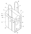
本発明の天蓋1は、保護カバー4の天面41を被覆可能な大きさに形成された天板11と、その左右辺部111から保護カバー4の側壁42に沿って垂下するように設けられた一対の側板を備える。また、本実施態様のように、天板11の前後辺部112には、それぞれ正面板13および背面板14を垂下するように設けても良い。かかる正面板13および背面板14を設けることで天蓋1全体の強度が上がり、また、前後方向からの雨により蜜蜂巣箱3の正面壁と背面壁が濡れにくくなるため好ましい。
The
天蓋1の天板11は、本実施態様ではその中央が最も上方へと突出する、いわゆる三角屋根形状に形成されているが、天板11の形状はこれに限定されず、平板状、略台形状、あるいはカマボコ状等その他の形状としてもよい。なお、天板11を単に平板状とするよりも、中央部分が高くなる立体的な形状に形成した方が、雨水等が天板11上に溜まることを防ぐことができるため、好ましい。
In the present embodiment, the
本実施態様では、天板11の左右辺部111から側板12側に、左右辺部111に沿ったスリット状の開口部が対に2箇所形成されている。このスリット開口部15は、側板12の前後方向の略中央部分に所定の幅及び高さに形成されており、かかるスリット開口部15に持ち手となるストラップ2を挿通することができる。
In this embodiment, two slit-shaped openings along the left and
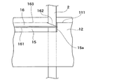
本実施態様のスリット開口部15の上辺には、突出片16が連設されている。本実施態様の突出片16は、天板11の一部が左右辺部111よりもさらに庇状に突出しており、その形状は、左右辺部111側となる基部163においてスリット開口部15の横幅よりも狭く、また、その先端部161においてスリット開口部15の横幅と略同一になるように、略台形状に形成されている。
A protruding
突出片16の形成手段は特に限定されないが、例えば、天板11と側板12を1枚の板材から左右辺部111となる部分で折り曲げ形成する場合は、あらかじめスリット開口部15の形状で左右辺部111から側板12側にかけて略コの字に切れ込みを入れておき、天板11を左右辺部111にて折り曲げたときに天板11の一部として突出片16部分を側板12から起立させればよい。そして、側板12から起立した突出片16の左右両端を略三角形に切り取れば、本実施態様のように、先端部161が幅広の略台形とすることができる。
The means for forming the projecting
突出片16は、スリット開口部15から一定の角度で起立し、外側へ突出するように形成されている。なお、本実施態様の突出片16は、傾斜している天板11からそのまま角度を変えることなく真っ直ぐに外側へ突出するように形成されているが、突出片16の突出角度を天板11から角度を変えて形成してもよく、例えば、突出片16が天板11の傾斜より上向き、あるいは、天板11の傾斜より下向きに突出するようにしてもよい。
The projecting
また、本実施態様の突出片16は略台形になるように形成されているが、突出片16の基部163の横幅がスリット開口部15の横幅よりも狭くなるように形成され、且つ、基部163とスリット開口部15の幅の差がストラップ2を挿通するのに十分な幅を有していれば、形状は略台形に限定されない。例えば、基部163と先端部161の横幅が同一の略矩形としてもよい。
Further, although the projecting
本実施態様のスリット開口部15は、天板11の左右辺部111から側板12の一部にかけて開口するように形成されているが、スリット開口部15の位置はこれに限定されず、天板11の一部もしくは左右辺部111の一部に設けられていればよい。すなわち、本実施態様ではスリット開口部15の上端部が左右辺部111と一致するが、かかる上端部を左右辺部111よりも天板11寄りもしくは側板12寄りにずらして形成してもよく、それに伴い、スリット開口部15の位置も、天板11と側板12の両方に跨るように、あるいは、天板11側もしくは側板12側のみで開口するように形成してもよい。
The slit opening 15 of the present embodiment is formed so as to open from the left and
スリット開口部15の幅及び高さについては特に制限はないが、強度や持ち運び際の安定性なども考慮すると、その横幅は10〜30cmの範囲、その縦幅は3mm〜50mmの範囲とすることが好ましい。また、スリット開口部15を本実施態様のように側板12側に設ける場合、その位置(高さ)は、側板12の高さのおよそ半分から上に位置することが好ましく、本実施態様のようにスリット開口部15の上端部が左右辺部111と一致する位置とすることがより好ましい。
The width and height of the slit opening 15 are not particularly limited, but the width should be in the range of 10 to 30 cm and the vertical width should be in the range of 3 mm to 50 mm in consideration of strength and stability during carrying. Is preferable. Further, when the slit opening 15 is provided on the
図2、4に示すように、本発明の天蓋1に取り付けられるストラップ2は1本のテープ状の両端部を繋げて環状に形成したものであり、使用されるストラップ2として、梱包に使用される一般的なPPバンド等を好適に利用することができる。 As shown in FIGS. A general PP band or the like can be preferably used.
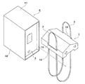
図2に示すように、ストラップ2は保護カバー4の両側壁42から底面にかけて2本が略平行になるように架け渡され、天蓋1の側板12の内側を通ってスリット開口部15部分から天蓋1の外側へ出されている。そして、ストラップ2は環状に形成されているため、スリット開口部15よりも上位部分では持ち手を形成する。
As shown in FIG. 2, two
図3はストラップ2を取り付けた部分を示す部分拡大図である。図に示すように、ストラップ2は側板12の内側を通り、スリット開口部15から外側上方へ出るように挿通されている。そして、突出片16は基部163がスリット開口部15の幅よりも狭く形成されており、これにより、基部163と開口部15の間にストラップ2が通る隙間が確保されている。また、本実施態様では突出片16が略台形に形成されているため、その側辺部162がストラップ2に対して「返し」の役割を果たし、ストラップ2が突出片16から外れて位置がずれることを効果的に防ぐことができる。
FIG. 3 is a partially enlarged view showing a portion to which the
また、突出片16は、ストラップ2の位置ずれ防止のほか、ストラップ2の係止手段としても利用することができる。すなわち、蜜蜂巣箱3を持ち運ぶ時以外、ストラップ2は不要となるが、その都度着脱するのも手間であり、付けっぱなしとなることが予想される。そこで、ストラップ2の不使用時には、ストラップ2の先端側21を反対側のスリット開口部15に形成された突出片16に引っ掛ければ、スリット開口部15からストラップ2が横に垂れるなどして邪魔になることを防ぐことができる。
Further, the protruding
なお、スリット開口部15の上辺には突出片16を設けることなく、ストラップ2を挿通可能なスリット開口部15のみ設けても良いが、ストラップ2の位置ずれを防ぐためには突出片16を設けることが好ましい。
The upper side of the slit opening 15 may not be provided with the protruding
天蓋1に対するストラップ2の取り付け方は以下の通りである。まず、環状に形成されたストラップ2の任意の部分を二つ折りとし、ストラップ2を二重にする。そして、かかる二つ折りした部分を側板12の下端部から側板12の内側へと入れ、そのまま上方のスリット開口部15まで通し、スリット開口部15に挿入して側板12の外側へと出す。このとき、ストラップ2はスリット開口部15のいずれかの端部(ここでは便宜的に端部15aとする)で突出片16とスリット開口部15の隙間に挿入すると作業がしやすい。
The method of attaching the
スリット開口部15に挿通した後、二つ折りに重ねられているストラップ2の一方を端部15a側にそのまま残し、他方を突出片16の先端部161とスリット開口部15の間を通して反対の端部15bへと移動させる。かかる作業を2箇所のスリット開口部15でそれぞれ行うことにより、天蓋1に対するストラップ2の取り付け作業が完了する。かかるストラップ2の取り付け作業は、天蓋1の蜜蜂巣箱3もしくは保護カバー4への取り付けの前に完了しておくことが望ましい。
After inserting through the slit opening 15, one of the
本発明の天蓋1の蜜蜂巣箱3もしくは保護カバー4への装着への装着方法は以下の通りである。図4に示すように、まず、ストラップ2をスリット開口部15よりも下方において長めに出しておき、天蓋1とストラップ2により中に蜜蜂巣箱3を挿入可能な環を作っておく。
The method of attaching the
次に、保護カバー4を装着した蜜蜂巣箱3を天蓋1とストラップ2の間の環に挿入し、2本のストラップ2が保護カバー4の側壁42と底面に略平行にかかるようにする。そして、天蓋1を保護カバー4の天壁41に被せ、スリット開口部15より下方の余っているストラップ2をスリット開口部15より上方へ引き出せば、保護カバー4への天蓋1の取り付けは完了する。
Next, the
なお、本実施態様では、天板11の左右辺部111に沿ってスリット開口部15が2箇所形成されているが、ストラップ2を挿通可能なサイズの開口部を左右辺部111に沿って4箇所設けてもよい。その場合、環状に形成する前のストラップ2を端部から順次、各開口部に挿通し、その後、ストラップ2の両端を結合して環状に形成すればよい。
In this embodiment, two
さらに、天蓋1の正面板13および/または背面板14には、係止爪17を設けても良い。かかる係止爪17は、正面板13および/または背面板14の一部を切り欠いて、その一部を屋根部材1の内側へと折り曲げることで形成される。本実施態様では、連接部171を残して、切断辺172において他の正面板13部分から切り離されて係止爪17が形成されている。使用時には連接部171部分から係止爪17を内側に折り曲げ突出させる。これにより、係止爪117の上辺部が蜜蜂巣箱3の一部、例えば、蓋部の下端部や、あるいは蜜蜂巣箱3に外装される保護カバー4の一部、例えば、天面41の裏面に係止され、天蓋1を蜜蜂巣箱3や保護カバー4に対して固定することが可能となる。
Further, the
さらに、天蓋1の天板11の裏側には断熱材を設けてもよい。かかる断熱材としては、発泡スチロールなどを好適に利用することができ、具体的には、蜜蜂巣箱3もしくは保護カバー4の天壁と同サイズの板状の断熱材を天板11の裏側に内設することができる。また、必要に応じて、かかる断熱材の固定手段を別途設けてもよい。
Further, a heat insulating material may be provided on the back side of the
さらに、天蓋1の正面板13には、本実施態様のようにその中央の下辺部の一部を凹状に切り欠いた凹部18を形成してもよい。かかる凹部18により、正面板13における作業時に正面板13が干渉しにくくなり、操作性が向上する。
Further, the
本発明の蜜蜂巣箱用天蓋は、天蓋1を載せられるサイズであれば、適用する蜜蜂巣箱3の種類等は特に限定されず、汎用的に使用することができる。また、保護カバー4を装着可能な蜜蜂巣箱3の場合は、本実施態様のように保護カバー4を装着した状態、あるいは、保護カバー4を取り外した状態のいずれの場合であっても、天蓋1を装着することができる。
The canopy for the bee hive of the present invention is not particularly limited in the type of the
本発明の蜜蜂巣箱用の天蓋1の材質としては、軽量で一定の強度を有する材質、例えば、ポリプロピレンやポリカーボネート製のプラ段や発泡スチロール等の合成樹脂、ダンボール、厚紙、ハードボード、パーティクルボード等で形成することが好ましい。その中でも、防水性を有するプラ段が特に好ましい。
The material of the
1 … … 天蓋
2 … … ストラップ
3 … … 蜜蜂巣箱
4 … … 保護カバー
11 … … 天板
12 … … 側板
13 … … 正面板
14 … … 背面板
15 … … スリット開口部
16 … … 突出片
17 … … 係止爪
18 … … 凹部
21 … … 先端側
31 … … 通気扉
32 … … 巣門
41 … … 天面
42 … … 側壁
111 … … 左右辺部
112 … … 前後辺部
161 … … 先端部
162 … … 側辺部
163 … … 基部
171 … … 連接部
172 … … 切断辺
1 ………
12 ………
Claims (7)
Priority Applications (1)
| Application Number | Priority Date | Filing Date | Title |
|---|---|---|---|
| JP2020034715A JP7356144B2 (en) | 2020-03-02 | 2020-03-02 | canopy for honey hive |
Applications Claiming Priority (1)
| Application Number | Priority Date | Filing Date | Title |
|---|---|---|---|
| JP2020034715A JP7356144B2 (en) | 2020-03-02 | 2020-03-02 | canopy for honey hive |
Publications (2)
| Publication Number | Publication Date |
|---|---|
| JP2021136870A true JP2021136870A (en) | 2021-09-16 |
| JP7356144B2 JP7356144B2 (en) | 2023-10-04 |
Family
ID=77666698
Family Applications (1)
| Application Number | Title | Priority Date | Filing Date |
|---|---|---|---|
| JP2020034715A Active JP7356144B2 (en) | 2020-03-02 | 2020-03-02 | canopy for honey hive |
Country Status (1)
| Country | Link |
|---|---|
| JP (1) | JP7356144B2 (en) |
Cited By (3)
| Publication number | Priority date | Publication date | Assignee | Title |
|---|---|---|---|---|
| JP2023053497A (en) * | 2021-10-01 | 2023-04-13 | 丸東東海商事株式会社 | Honeycomb box for pollination and bee hive cover |
| JP2023129832A (en) * | 2022-03-07 | 2023-09-20 | 丸東東海商事株式会社 | Bee hive box for pollination and hive box cover |
| JP7496656B1 (en) | 2024-01-30 | 2024-06-07 | 丸東東海商事株式会社 | Beehive |
Citations (9)
| Publication number | Priority date | Publication date | Assignee | Title |
|---|---|---|---|---|
| US4402099A (en) * | 1981-05-04 | 1983-09-06 | Chevron Research | Beehive for improved beekeeping in tropical countries |
| JP3022437U (en) * | 1995-09-06 | 1996-03-26 | トーホー工業株式会社 | Souvenir container |
| JP2002058379A (en) * | 2000-08-16 | 2002-02-26 | Nippon Express Co Ltd | Holding stand for beehive and beehive for transportation using the same |
| JP2005333816A (en) * | 2004-05-24 | 2005-12-08 | Iris Ohyama Inc | Cover for small animal housing body |
| JP2007143428A (en) * | 2005-11-24 | 2007-06-14 | Maruto Tokai Shoji Kk | Hive for pollination bee |
| JP3197753U (en) * | 2015-03-16 | 2015-06-04 | 恵里 梅山 | Carry for storage container |
| JP3217822U (en) * | 2018-05-09 | 2018-09-06 | 株式会社エンゼル産業 | Honeycomb box ventilation insulation box |
| JP2019018915A (en) * | 2017-07-20 | 2019-02-07 | 青山 淳 | Detachable handle |
| JP2020115836A (en) * | 2019-01-28 | 2020-08-06 | トーホー工業株式会社 | Bee-keeping box insulation container |
-
2020
- 2020-03-02 JP JP2020034715A patent/JP7356144B2/en active Active
Patent Citations (9)
| Publication number | Priority date | Publication date | Assignee | Title |
|---|---|---|---|---|
| US4402099A (en) * | 1981-05-04 | 1983-09-06 | Chevron Research | Beehive for improved beekeeping in tropical countries |
| JP3022437U (en) * | 1995-09-06 | 1996-03-26 | トーホー工業株式会社 | Souvenir container |
| JP2002058379A (en) * | 2000-08-16 | 2002-02-26 | Nippon Express Co Ltd | Holding stand for beehive and beehive for transportation using the same |
| JP2005333816A (en) * | 2004-05-24 | 2005-12-08 | Iris Ohyama Inc | Cover for small animal housing body |
| JP2007143428A (en) * | 2005-11-24 | 2007-06-14 | Maruto Tokai Shoji Kk | Hive for pollination bee |
| JP3197753U (en) * | 2015-03-16 | 2015-06-04 | 恵里 梅山 | Carry for storage container |
| JP2019018915A (en) * | 2017-07-20 | 2019-02-07 | 青山 淳 | Detachable handle |
| JP3217822U (en) * | 2018-05-09 | 2018-09-06 | 株式会社エンゼル産業 | Honeycomb box ventilation insulation box |
| JP2020115836A (en) * | 2019-01-28 | 2020-08-06 | トーホー工業株式会社 | Bee-keeping box insulation container |
Cited By (5)
| Publication number | Priority date | Publication date | Assignee | Title |
|---|---|---|---|---|
| JP2023053497A (en) * | 2021-10-01 | 2023-04-13 | 丸東東海商事株式会社 | Honeycomb box for pollination and bee hive cover |
| JP7400163B2 (en) | 2021-10-01 | 2023-12-19 | 丸東東海商事株式会社 | Bee hives and hive covers for pollination |
| JP2023129832A (en) * | 2022-03-07 | 2023-09-20 | 丸東東海商事株式会社 | Bee hive box for pollination and hive box cover |
| JP7416453B2 (en) | 2022-03-07 | 2024-01-17 | 丸東東海商事株式会社 | Bee hives and hive covers for pollination |
| JP7496656B1 (en) | 2024-01-30 | 2024-06-07 | 丸東東海商事株式会社 | Beehive |
Also Published As
| Publication number | Publication date |
|---|---|
| JP7356144B2 (en) | 2023-10-04 |
Similar Documents
| Publication | Publication Date | Title |
|---|---|---|
| JP2021136870A (en) | Canopy for beehive | |
| US7044083B2 (en) | Pet enclosure | |
| US6446577B1 (en) | Insulated cover for portable kennel | |
| US9706749B2 (en) | Collapsible animal enclosure | |
| US4726141A (en) | Fishing rod and reel carrying case | |
| US6978736B2 (en) | Collapsible kennel for use with capped truck beds | |
| JP6713380B2 (en) | Honeycomb box | |
| US20150313200A1 (en) | Fishing rod and reel carrying case system | |
| KR102159309B1 (en) | Beehives molded from foamed resin | |
| US5913500A (en) | Tool hanging device | |
| JP6713390B2 (en) | Bee hive protector | |
| GB2467412A (en) | Portable and Collapsible Housing for Poultry or Other Animals | |
| US10399749B1 (en) | Lid for a flat back bucket | |
| CA1158490A (en) | Animal kennel | |
| JPH01500323A (en) | collapsible shipping box | |
| JP2005082207A (en) | Waterproof implement | |
| JP7416453B2 (en) | Bee hives and hive covers for pollination | |
| US6637373B2 (en) | Nesting box | |
| US11871740B2 (en) | Protective fishing hook and lure cover | |
| JP7351562B2 (en) | Car trolley covers and luggage covers | |
| JPS6129258Y2 (en) | ||
| JPH0636694Y2 (en) | Folding beekeeping box | |
| JPH0642001Y2 (en) | Balcony with storage | |
| JP2023053497A (en) | Honeycomb box for pollination and bee hive cover | |
| US20100213225A1 (en) | Pack For Roofing Shingles |
Legal Events
| Date | Code | Title | Description |
|---|---|---|---|
| A621 | Written request for application examination |
Free format text: JAPANESE INTERMEDIATE CODE: A621 Effective date: 20220908 |
|
| RD02 | Notification of acceptance of power of attorney |
Free format text: JAPANESE INTERMEDIATE CODE: A7422 Effective date: 20230206 |
|
| A521 | Request for written amendment filed |
Free format text: JAPANESE INTERMEDIATE CODE: A821 Effective date: 20230208 |
|
| RD04 | Notification of resignation of power of attorney |
Free format text: JAPANESE INTERMEDIATE CODE: A7424 Effective date: 20230316 |
|
| A977 | Report on retrieval |
Free format text: JAPANESE INTERMEDIATE CODE: A971007 Effective date: 20230711 |
|
| A131 | Notification of reasons for refusal |
Free format text: JAPANESE INTERMEDIATE CODE: A131 Effective date: 20230718 |
|
| A521 | Request for written amendment filed |
Free format text: JAPANESE INTERMEDIATE CODE: A523 Effective date: 20230724 |
|
| TRDD | Decision of grant or rejection written | ||
| A01 | Written decision to grant a patent or to grant a registration (utility model) |
Free format text: JAPANESE INTERMEDIATE CODE: A01 Effective date: 20230912 |
|
| A61 | First payment of annual fees (during grant procedure) |
Free format text: JAPANESE INTERMEDIATE CODE: A61 Effective date: 20230914 |
|
| R150 | Certificate of patent or registration of utility model |
Ref document number: 7356144 Country of ref document: JP Free format text: JAPANESE INTERMEDIATE CODE: R150 |


