JP2021136841A - Power supply system - Google Patents
Power supply system Download PDFInfo
- Publication number
- JP2021136841A JP2021136841A JP2020033854A JP2020033854A JP2021136841A JP 2021136841 A JP2021136841 A JP 2021136841A JP 2020033854 A JP2020033854 A JP 2020033854A JP 2020033854 A JP2020033854 A JP 2020033854A JP 2021136841 A JP2021136841 A JP 2021136841A
- Authority
- JP
- Japan
- Prior art keywords
- power
- bicycle
- power supply
- antenna
- transmitting antenna
- Prior art date
- Legal status (The legal status is an assumption and is not a legal conclusion. Google has not performed a legal analysis and makes no representation as to the accuracy of the status listed.)
- Pending
Links
Images
Landscapes
- Charge And Discharge Circuits For Batteries Or The Like (AREA)
- Professional, Industrial, Or Sporting Protective Garments (AREA)
Abstract
【課題】自転車を利用しながら電子機器にワイヤレスで電力を供給することができる給電システムを提供する。
【解決手段】給電システムにおいて、衣服に取り付けられた導電性繊維からなり、電子機器に接続可能な受信用アンテナに、自転車の送信用アンテナ2からワイヤレス給電する。送信用アンテナ2は、自転車のサドル1に配置されている。
【選択図】図2PROBLEM TO BE SOLVED: To provide a power supply system capable of wirelessly supplying electric power to an electronic device while using a bicycle.
SOLUTION: In a power feeding system, a receiving antenna made of conductive fibers attached to clothes and connectable to an electronic device is wirelessly fed from a bicycle transmitting antenna 2. The transmitting antenna 2 is arranged on the saddle 1 of the bicycle.
[Selection diagram] Fig. 2
Description
本発明は、自転車に取り付けた送信用アンテナから、乗輪者が電力を受信することができる給電システムに関する。 The present invention relates to a power supply system that allows a passenger to receive electric power from a transmitting antenna attached to a bicycle.
従来から、脈波や心拍数、溶存酸素量の測定を行うことができるバイタルセンサやスマートウォッチなどのウェアラブル電子機器が広く利用されている。この種の電子機器は、その重量を抑えるため、小型の一次電池あるいは二次電池から電力が供給される。ところで小型の一次電池等は消耗が早く、長時間にわたり使用する場合には、予備の一次電池等を持ち歩かなければならない。 Conventionally, wearable electronic devices such as vital sensors and smart watches that can measure pulse waves, heart rate, and dissolved oxygen content have been widely used. This type of electronic device is powered by a small primary or secondary battery to reduce its weight. By the way, a small primary battery or the like wears out quickly, and when it is used for a long time, it is necessary to carry a spare primary battery or the like.
一方本願出願人は、導電糸を織り込み、電子機器に接続可能な繊維構造体を開示している(特許文献1)。この種の繊維構造体は、金属製の導体の代わりに利用することができる。 On the other hand, the applicant of the present application discloses a fiber structure in which a conductive thread is woven and can be connected to an electronic device (Patent Document 1). This type of fiber structure can be used in place of metal conductors.
ウェアラブル電子機器に電力を供給する一次電池等を小型化すると、電池交換を頻繁に行う必要があったり、予備の電池を持ち歩く必要があった。本発明はこのような実状に鑑み、自転車を利用しながら電子機器にワイヤレスで電力を供給することができる給電システムを提供することを目的とする。 When the primary batteries and the like that supply electric power to wearable electronic devices are miniaturized, it is necessary to frequently replace the batteries or carry a spare battery with them. In view of such circumstances, an object of the present invention is to provide a power supply system capable of wirelessly supplying electric power to an electronic device while using a bicycle.
上記目的を達成するため、本願請求項1に係る発明は、衣服に取り付けられた導電性繊維からなり電子機器に接続可能な受信用アンテナに、自転車の送信用アンテナからワイヤレス給電する給電システムであって、前記送信用アンテナは、前記自転車のサドルに配置されていることを特徴とする。
In order to achieve the above object, the invention according to
本願請求項2に係る発明は、請求項1記載の給電システムにおいて、前記送信用アンテナから送信される電力は、前記自転車に備えられた発電手段により発電された電力、あるいは前記自転車に備えられた二次電池から供給される電力であることを特徴とする。 According to the second aspect of the present application, in the power supply system according to the first aspect, the electric power transmitted from the transmitting antenna is the electric power generated by the power generation means provided in the bicycle or the electric power provided in the bicycle. It is characterized by being electric power supplied from a secondary battery.
本願請求項3に係る発明は、請求項1または2いずれか記載の給電システムにおいて、前記送信用アンテナから電力の送信を停止する手段を備えていることを特徴とする。
The invention according to
本発明の給電システムは、自転車のサドルに送信用アンテナを配置し、乗輪者がサドルに跨ることで、乗輪者の衣服の一部に取り付けられた受信用アンテナと送信用アンテナとを対向配置され、送信用アンテナから受信用アンテナへワイヤレス給電することを可能としている。この給電により、一次電池の消耗を遅らせたり、二次電池を充電することが可能となる。その結果、電池交換を頻繁に行わずに電子機器を長時間使用することが可能となる。 In the power feeding system of the present invention, a transmitting antenna is arranged on the saddle of the bicycle, and the passenger straddles the saddle so that the receiving antenna attached to a part of the passenger's clothes and the transmitting antenna face each other. It is arranged and enables wireless power supply from the transmitting antenna to the receiving antenna. This power supply makes it possible to delay the consumption of the primary battery and charge the secondary battery. As a result, the electronic device can be used for a long time without frequently replacing the battery.
特に本発明は、自転車に備えられたダイナモや太陽電池のような発電手段により発電される電力や、自転車に備えられた二次電池の電力を自転車のサドルに配置した送信用アンテナから送信するため、電力供給装置と送信用アンテナとを接続する配線を追加するだけでよく、簡便な構成となる。 In particular, the present invention is to transmit the electric power generated by a power generation means such as a dynamo or a solar cell provided in a bicycle or the electric power of a secondary battery provided in the bicycle from a transmission antenna arranged in the saddle of the bicycle. , It is only necessary to add a wiring for connecting the power supply device and the transmission antenna, and the configuration is simple.
また受信用アンテナが存在しない場合、あるいは電子機器の二次電池がフル充電状態の場合には、受信アンテナへの電力供給がないこと等を検知することで、電力の送信を簡便に停止することができ、送信用アンテナから不要な電磁界を放出することも防止できる。 In addition, when the receiving antenna does not exist, or when the secondary battery of the electronic device is in a fully charged state, it is possible to easily stop the power transmission by detecting that there is no power supply to the receiving antenna. It is also possible to prevent the emission of unnecessary electromagnetic fields from the transmitting antenna.
本発明の給電システムは、自転車のサドルに送信用アンテナを備え、乗輪者がサドルに跨ることで、乗輪者の衣服の一部に取り付けられた受信用アンテナとサドルの送信用アンテナとを対向配置させ、送信用アンテナから受信用アンテナへワイヤレス給電を可能としている。以下、本発明の実施例について詳細に説明する。 In the power feeding system of the present invention, the saddle of the bicycle is provided with a transmitting antenna, and when the passenger straddles the saddle, the receiving antenna attached to a part of the passenger's clothes and the transmitting antenna of the saddle are connected. They are placed facing each other to enable wireless power supply from the transmitting antenna to the receiving antenna. Hereinafter, examples of the present invention will be described in detail.
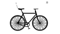
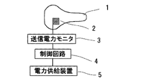
本発明の実施例について説明する。図1は本発明の給電システムを備える自転車10を、図2は図1に示す自転車の給電システムの説明図をそれぞれ示す。図1および図2に示すように、自転車10のサドル1に送信用アンテナ2を配置し、この送信用アンテナ2に送電電力モニタ3、制御回路4、自転車に備えられたダイナモや太陽電池等の発電装置(発電手段)あるいは二次電池等からなる電力供給装置5が接続した構成となっている。サドル1に配置される送信用アンテナ2は、サドル1の内部に送電電力モニタ3および制御回路4とともに埋設し、乗輪者の乗り心地の良さを損なわないようにする。当然ながら、送信用アンテナ2上に、電力の送信を妨げるものは配置しない。
Examples of the present invention will be described. FIG. 1 shows a
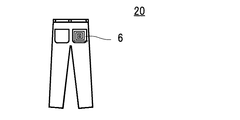
図3は、乗輪者が身に着ける衣服20の一例である。図3に示す例では、乗輪者の臀部のポケットに受信用アンテナ6を配置している。この受信用アンテナ6は、導電性繊維をらせん状に巻いて形成することができる。このように配置すると、乗輪者が図1に示す自転車10のサドル1に跨ることで、図2に示す送信用アンテナ2と衣服20の受信用アンテナ6が対向配置され、電力供給が可能となる。
FIG. 3 is an example of
ここで、受信用アンテナ6が例えば金属線のような硬い材料で構成されていると、硬い材料が臀部に当たり乗輪者は不快と感じることになる。しかしながら本実施例のように受信用アンテナ6を導電性繊維によって形成することで、乗輪者が不快と感じることを防止できる。
Here, if the
送信用アンテナ2と受信用アンテナ6との電力の送受信は、電磁誘導方式、磁界共鳴方式等の通常のワイヤレス給電方式により行うことができる。
Power can be transmitted and received between the transmitting
なお図3では受信用アンテナ6のみを図示し、電力を供給する電子機器および電子機器との接続を図示していないが、これらの接続は周知の方法を採用することができる。例えば、受信用アンテナ6に接続するコネクタを衣服20に形成しておき、このコネクタに電子機器、あるいは電子機器に接続するコネクタを接続すればよい。コネクタから取り外して電子機器を分離できることは、衣服20を洗濯する場合に好適である。また受信用アンテナ6に接続する配線も導電性繊維とし、例えば乗輪者の上着の胸ポケットに電子機器を入れ、この電子機器に接続するように上着に導電性繊維によって配線を配置し、さらにこの配線を図3に示すようにズボンに形成した受信用アンテナ6に接続するようにしてもよい。
Although only the receiving
ところで、自転車のサドル1に配置した送信用アンテナ2と乗輪者の衣服に形成された受信用アンテナ6が、完全に重なり合うことは必ずしも必須ではない。また送信用アンテナ2はサドル1内に配置するため、衣服20に配置される受信用アンテナ6とは、例えば5mm程度離れた状態となっている。一例として、人体への影響のない範囲の周波数4MHzの電力を送受信する場合、送信用アンテナ2と受信用アンテナ6とをズレなく配置した場合の受信電力を100Ω負荷電流換算した電流値を100%とした場合、送信用アンテナ2と受信用アンテナ6とが完全にずれた場合でも電流値が22%となり電力供給は可能である。また、送信用アンテナ2と受信用アンテナ6が重なり、その間隔が離れた場合、具体的には通常状態より2cm程度離れた場合には、電流値が60%のレベルの給電が可能となる。
By the way, it is not always essential that the transmitting
本実施例の給電システムでは、制御回路3を備えることができる。この制御回路3では、送信用アンテナ2から送信される送信信号の周波数、出力電力等を制御することができる。例えば、電磁誘導現象や電磁界共鳴現象を用いたワイヤレス給電システムでは、電力の伝送に用いる電磁界が周囲の電子機器への妨害や人体への影響を少なくするための種々の規制が行われる。このような規制をクリアするため制御回路3により電力伝送を制御すればよい。例えば、人体への影響の少なくするため伝送する電力の周波数帯域は、4MHz程度以下に制御するのが好ましい。一方、衣類20に受信する電力が人体に影響与えないようなシールド構造を付加すれば、より効率の高い周波数帯域の伝送を行うように制御することも可能である。
The power supply system of this embodiment may include a
また受信用アンテナ6が存在しない場合、あるいは電子機器の二次電池がフル充電状態の場合には、受信用アンテナ6への電力供給がないため、送信用アンテナ2への電力供給状態を送信電力モニタ3で、負荷が非常に軽いことを検出して電力の送信を停止することができる。あるいは別の方法として、給電システムの初期状態として受信用アンテナ6がない状態の送信用アンテナ2の状態を記録しておき、その初期状態と現在の送信用アンテナ2の状態とを比較して受信用アンテナ6がないことを検知するように構成しても電力の送信を簡便に停止することができる。このように制御することで、送信用アンテナ2から不要な電磁界を放出することも防止できる。
If the receiving
一般的に自転車10には、ダイナモや太陽電池等の発電装置や二次電池のような電力供給装置5を備えている。本発明の給電システムは、これらの電力供給装置5から電力を供給することができる。この電力供給装置5と送電用アンテナ2とは、自転車10のフレームに沿って配線すれば、乗輪者の安全を損なうことも無い。
Generally, the
以上本発明の実施例について説明したが、本発明は上記実施例に限定されるものでないことは言うまでもない。例えば、サドル1に配置される送信用アンテナ2は、1個に限らず、複数個配置することができ、受信用アンテナ6の位置に応じて、複数個の送信用アンテナ2の電力送信を制御回路4により制御することも可能である。電力を供給する電子機器は、バイタルセンサやスマートウォッチの他、スマートフォンのような携帯機器であってもよい。
Although the examples of the present invention have been described above, it goes without saying that the present invention is not limited to the above examples. For example, the
1:サドル、2:送信用アンテナ、3:送信電力モニタ、4:制御回路、5:電力供給装置、6:受信用アンテナ、10:自転車、20:衣服 1: Saddle, 2: Transmission antenna, 3: Transmission power monitor, 4: Control circuit, 5: Power supply device, 6: Reception antenna, 10: Bicycle, 20: Clothes
Claims (3)
前記送信用アンテナは、前記自転車のサドルに配置されていることを特徴とする給電システム。 It is a power supply system that wirelessly supplies power to a receiving antenna made of conductive fibers attached to clothes and can be connected to electronic devices from a bicycle transmitting antenna.
The power feeding system is characterized in that the transmitting antenna is arranged in the saddle of the bicycle.
Priority Applications (1)
| Application Number | Priority Date | Filing Date | Title |
|---|---|---|---|
| JP2020033854A JP2021136841A (en) | 2020-02-28 | 2020-02-28 | Power supply system |
Applications Claiming Priority (1)
| Application Number | Priority Date | Filing Date | Title |
|---|---|---|---|
| JP2020033854A JP2021136841A (en) | 2020-02-28 | 2020-02-28 | Power supply system |
Publications (1)
| Publication Number | Publication Date |
|---|---|
| JP2021136841A true JP2021136841A (en) | 2021-09-13 |
Family
ID=77661882
Family Applications (1)
| Application Number | Title | Priority Date | Filing Date |
|---|---|---|---|
| JP2020033854A Pending JP2021136841A (en) | 2020-02-28 | 2020-02-28 | Power supply system |
Country Status (1)
| Country | Link |
|---|---|
| JP (1) | JP2021136841A (en) |
Citations (12)
| Publication number | Priority date | Publication date | Assignee | Title |
|---|---|---|---|---|
| JP2008542565A (en) * | 2005-05-31 | 2008-11-27 | コーニンクレッカ フィリップス エレクトロニクス エヌ ヴィ | Fully woven electrode layout that allows passive matrix addressing and active matrix addressing |
| JP2009011129A (en) * | 2007-06-29 | 2009-01-15 | Seiko Epson Corp | Power transmission control device, power transmission device, non-contact power transmission system, and electronic device |
| JP2010098861A (en) * | 2008-10-16 | 2010-04-30 | Sanyo Electric Co Ltd | Charger apparatus of mobile electronic device |
| JP2010149747A (en) * | 2008-12-25 | 2010-07-08 | Honda Motor Co Ltd | Airbag device |
| US20130032589A1 (en) * | 2010-04-26 | 2013-02-07 | Korea Institute Of Industrial Technology | Contactlessly chargeable heater |
| JP2014204539A (en) * | 2013-04-03 | 2014-10-27 | 船井電機株式会社 | Non-contact power feeder and non-contact power feeding method |
| JP2017050947A (en) * | 2015-08-31 | 2017-03-09 | キヤノン株式会社 | Power transmission device, control method, and program |
| EP3192383A1 (en) * | 2016-01-12 | 2017-07-19 | Francisco Lobato Raposo | Autonomous removable signalling system for users of cabin-less vehicle |
| US20170271922A1 (en) * | 2016-03-17 | 2017-09-21 | Industry-Academic Cooperation Foundation, Chosun University | Apparatus and method of charging mobile terminal using energy harvesting device |
| US20180160976A1 (en) * | 2014-11-10 | 2018-06-14 | Unist (Ulsan National Institute Of Science And Technology) | Biosensor, transparent circuitry and contact lens including same |
| US20180352875A1 (en) * | 2017-06-13 | 2018-12-13 | Analog Devices, Inc. | System and method for wireless charging of smart garments |
| DE102018202193A1 (en) * | 2018-02-13 | 2019-08-14 | Osram Gmbh | Clothing, vehicle, arrangement and procedures |
-
2020
- 2020-02-28 JP JP2020033854A patent/JP2021136841A/en active Pending
Patent Citations (12)
| Publication number | Priority date | Publication date | Assignee | Title |
|---|---|---|---|---|
| JP2008542565A (en) * | 2005-05-31 | 2008-11-27 | コーニンクレッカ フィリップス エレクトロニクス エヌ ヴィ | Fully woven electrode layout that allows passive matrix addressing and active matrix addressing |
| JP2009011129A (en) * | 2007-06-29 | 2009-01-15 | Seiko Epson Corp | Power transmission control device, power transmission device, non-contact power transmission system, and electronic device |
| JP2010098861A (en) * | 2008-10-16 | 2010-04-30 | Sanyo Electric Co Ltd | Charger apparatus of mobile electronic device |
| JP2010149747A (en) * | 2008-12-25 | 2010-07-08 | Honda Motor Co Ltd | Airbag device |
| US20130032589A1 (en) * | 2010-04-26 | 2013-02-07 | Korea Institute Of Industrial Technology | Contactlessly chargeable heater |
| JP2014204539A (en) * | 2013-04-03 | 2014-10-27 | 船井電機株式会社 | Non-contact power feeder and non-contact power feeding method |
| US20180160976A1 (en) * | 2014-11-10 | 2018-06-14 | Unist (Ulsan National Institute Of Science And Technology) | Biosensor, transparent circuitry and contact lens including same |
| JP2017050947A (en) * | 2015-08-31 | 2017-03-09 | キヤノン株式会社 | Power transmission device, control method, and program |
| EP3192383A1 (en) * | 2016-01-12 | 2017-07-19 | Francisco Lobato Raposo | Autonomous removable signalling system for users of cabin-less vehicle |
| US20170271922A1 (en) * | 2016-03-17 | 2017-09-21 | Industry-Academic Cooperation Foundation, Chosun University | Apparatus and method of charging mobile terminal using energy harvesting device |
| US20180352875A1 (en) * | 2017-06-13 | 2018-12-13 | Analog Devices, Inc. | System and method for wireless charging of smart garments |
| DE102018202193A1 (en) * | 2018-02-13 | 2019-08-14 | Osram Gmbh | Clothing, vehicle, arrangement and procedures |
Similar Documents
| Publication | Publication Date | Title |
|---|---|---|
| US9859747B2 (en) | Garment device and system having wireless charging function, and charging method using the same | |
| JP4804530B2 (en) | System, inductive power supply, energizing load, and method enabling wireless power transfer | |
| EP4238493A2 (en) | Fabric-based items with stretchable bands | |
| JP2005287150A5 (en) | ||
| US10396584B2 (en) | Wireless charging steering wheel | |
| JP3210770U (en) | Coil structure for improved inductive energy transmission | |
| CN104813420A (en) | Wireless charging systems and methods | |
| JP2012044827A (en) | Non-contact charger | |
| CN106487048B (en) | Method, device and system for charging terminal | |
| MX2016003671A (en) | Self-contained branch circuit monitor. | |
| CN219802669U (en) | Electronic module comprising a printed circuit board structure | |
| CN107866001A (en) | A kind of more protection pacemaker devices | |
| KR20150070691A (en) | belt system capable wireless charging | |
| JP2021136841A (en) | Power supply system | |
| TW201524072A (en) | Wearable electronic apparatus | |
| US20180168506A1 (en) | Modular intelligent clothing | |
| CN105932744A (en) | Wireless charging method and system and intelligent jewelry | |
| CN106901423A (en) | Weaving article unit and/or apparatus | |
| JP5148890B2 (en) | Medical telemeter transmitter, charger, transmission method and charging method | |
| JP3205282U (en) | Hydrogen generator powered by wireless power | |
| US20240216706A1 (en) | Wearable garment with integrated tumor treating fields voltage generator | |
| FI123360B (en) | Procedures and equipment for measuring heart rate | |
| KR102165408B1 (en) | Biometric information monitoring device charging system and monitering device thereof | |
| KR20170083893A (en) | A Portable Heating Pad Device Having a Structure of Magnetic Resonance | |
| CN204969501U (en) | Can realize intelligent underwear of wireless monitoring rhythm of heart and electrocardiogram |
Legal Events
| Date | Code | Title | Description |
|---|---|---|---|
| A621 | Written request for application examination |
Free format text: JAPANESE INTERMEDIATE CODE: A621 Effective date: 20221228 |
|
| A977 | Report on retrieval |
Free format text: JAPANESE INTERMEDIATE CODE: A971007 Effective date: 20231026 |
|
| RD07 | Notification of extinguishment of power of attorney |
Free format text: JAPANESE INTERMEDIATE CODE: A7427 Effective date: 20231107 |
|
| A131 | Notification of reasons for refusal |
Free format text: JAPANESE INTERMEDIATE CODE: A131 Effective date: 20231114 |
|
| A521 | Request for written amendment filed |
Free format text: JAPANESE INTERMEDIATE CODE: A523 Effective date: 20231226 |
|
| RD02 | Notification of acceptance of power of attorney |
Free format text: JAPANESE INTERMEDIATE CODE: A7422 Effective date: 20231226 |
|
| A131 | Notification of reasons for refusal |
Free format text: JAPANESE INTERMEDIATE CODE: A131 Effective date: 20240220 |
|
| A02 | Decision of refusal |
Free format text: JAPANESE INTERMEDIATE CODE: A02 Effective date: 20240820 |