JP2021108533A - Method and device for discharge - Google Patents
Method and device for discharge Download PDFInfo
- Publication number
- JP2021108533A JP2021108533A JP2020217113A JP2020217113A JP2021108533A JP 2021108533 A JP2021108533 A JP 2021108533A JP 2020217113 A JP2020217113 A JP 2020217113A JP 2020217113 A JP2020217113 A JP 2020217113A JP 2021108533 A JP2021108533 A JP 2021108533A
- Authority
- JP
- Japan
- Prior art keywords
- discharge
- power
- discharge circuit
- voltage
- circuit
- Prior art date
- Legal status (The legal status is an assumption and is not a legal conclusion. Google has not performed a legal analysis and makes no representation as to the accuracy of the status listed.)
- Pending
Links
- 238000000034 method Methods 0.000 title claims description 22
- 239000003990 capacitor Substances 0.000 claims abstract description 45
- 230000004044 response Effects 0.000 claims description 32
- 238000007599 discharging Methods 0.000 claims description 28
- 208000028659 discharge Diseases 0.000 description 1061
- 238000006243 chemical reaction Methods 0.000 description 14
- 230000006870 function Effects 0.000 description 9
- 238000012545 processing Methods 0.000 description 7
- 230000008859 change Effects 0.000 description 6
- 230000001276 controlling effect Effects 0.000 description 5
- 238000004891 communication Methods 0.000 description 4
- 238000012423 maintenance Methods 0.000 description 3
- 230000009467 reduction Effects 0.000 description 3
- 230000000694 effects Effects 0.000 description 2
- 230000006872 improvement Effects 0.000 description 2
- 230000000977 initiatory effect Effects 0.000 description 2
- 238000005259 measurement Methods 0.000 description 2
- 238000012986 modification Methods 0.000 description 2
- 230000004048 modification Effects 0.000 description 2
- 230000008569 process Effects 0.000 description 2
- 230000001360 synchronised effect Effects 0.000 description 2
- 230000007704 transition Effects 0.000 description 2
- 230000009471 action Effects 0.000 description 1
- 238000013459 approach Methods 0.000 description 1
- 230000008901 benefit Effects 0.000 description 1
- 239000004020 conductor Substances 0.000 description 1
- 238000010586 diagram Methods 0.000 description 1
- 230000005611 electricity Effects 0.000 description 1
- 239000000446 fuel Substances 0.000 description 1
- 231100001261 hazardous Toxicity 0.000 description 1
- 238000002955 isolation Methods 0.000 description 1
- 230000007257 malfunction Effects 0.000 description 1
- 239000000463 material Substances 0.000 description 1
- 230000005055 memory storage Effects 0.000 description 1
- 230000000704 physical effect Effects 0.000 description 1
- 230000001105 regulatory effect Effects 0.000 description 1
- 230000000630 rising effect Effects 0.000 description 1
- 238000012546 transfer Methods 0.000 description 1
Images


Classifications
-
- H—ELECTRICITY
- H02—GENERATION; CONVERSION OR DISTRIBUTION OF ELECTRIC POWER
- H02M—APPARATUS FOR CONVERSION BETWEEN AC AND AC, BETWEEN AC AND DC, OR BETWEEN DC AND DC, AND FOR USE WITH MAINS OR SIMILAR POWER SUPPLY SYSTEMS; CONVERSION OF DC OR AC INPUT POWER INTO SURGE OUTPUT POWER; CONTROL OR REGULATION THEREOF
- H02M1/00—Details of apparatus for conversion
- H02M1/32—Means for protecting converters other than automatic disconnection
-
- H—ELECTRICITY
- H02—GENERATION; CONVERSION OR DISTRIBUTION OF ELECTRIC POWER
- H02H—EMERGENCY PROTECTIVE CIRCUIT ARRANGEMENTS
- H02H9/00—Emergency protective circuit arrangements for limiting excess current or voltage without disconnection
- H02H9/04—Emergency protective circuit arrangements for limiting excess current or voltage without disconnection responsive to excess voltage
-
- H—ELECTRICITY
- H02—GENERATION; CONVERSION OR DISTRIBUTION OF ELECTRIC POWER
- H02J—CIRCUIT ARRANGEMENTS OR SYSTEMS FOR SUPPLYING OR DISTRIBUTING ELECTRIC POWER; SYSTEMS FOR STORING ELECTRIC ENERGY
- H02J3/00—Circuit arrangements for ac mains or ac distribution networks
- H02J3/38—Arrangements for parallely feeding a single network by two or more generators, converters or transformers
- H02J3/388—Islanding, i.e. disconnection of local power supply from the network
-
- H—ELECTRICITY
- H02—GENERATION; CONVERSION OR DISTRIBUTION OF ELECTRIC POWER
- H02M—APPARATUS FOR CONVERSION BETWEEN AC AND AC, BETWEEN AC AND DC, OR BETWEEN DC AND DC, AND FOR USE WITH MAINS OR SIMILAR POWER SUPPLY SYSTEMS; CONVERSION OF DC OR AC INPUT POWER INTO SURGE OUTPUT POWER; CONTROL OR REGULATION THEREOF
- H02M1/00—Details of apparatus for conversion
- H02M1/36—Means for starting or stopping converters
-
- H—ELECTRICITY
- H02—GENERATION; CONVERSION OR DISTRIBUTION OF ELECTRIC POWER
- H02M—APPARATUS FOR CONVERSION BETWEEN AC AND AC, BETWEEN AC AND DC, OR BETWEEN DC AND DC, AND FOR USE WITH MAINS OR SIMILAR POWER SUPPLY SYSTEMS; CONVERSION OF DC OR AC INPUT POWER INTO SURGE OUTPUT POWER; CONTROL OR REGULATION THEREOF
- H02M3/00—Conversion of dc power input into dc power output
- H02M3/02—Conversion of dc power input into dc power output without intermediate conversion into ac
- H02M3/04—Conversion of dc power input into dc power output without intermediate conversion into ac by static converters
- H02M3/10—Conversion of dc power input into dc power output without intermediate conversion into ac by static converters using discharge tubes with control electrode or semiconductor devices with control electrode
- H02M3/145—Conversion of dc power input into dc power output without intermediate conversion into ac by static converters using discharge tubes with control electrode or semiconductor devices with control electrode using devices of a triode or transistor type requiring continuous application of a control signal
- H02M3/155—Conversion of dc power input into dc power output without intermediate conversion into ac by static converters using discharge tubes with control electrode or semiconductor devices with control electrode using devices of a triode or transistor type requiring continuous application of a control signal using semiconductor devices only
-
- H—ELECTRICITY
- H02—GENERATION; CONVERSION OR DISTRIBUTION OF ELECTRIC POWER
- H02M—APPARATUS FOR CONVERSION BETWEEN AC AND AC, BETWEEN AC AND DC, OR BETWEEN DC AND DC, AND FOR USE WITH MAINS OR SIMILAR POWER SUPPLY SYSTEMS; CONVERSION OF DC OR AC INPUT POWER INTO SURGE OUTPUT POWER; CONTROL OR REGULATION THEREOF
- H02M7/00—Conversion of ac power input into dc power output; Conversion of dc power input into ac power output
- H02M7/42—Conversion of dc power input into ac power output without possibility of reversal
- H02M7/44—Conversion of dc power input into ac power output without possibility of reversal by static converters
- H02M7/48—Conversion of dc power input into ac power output without possibility of reversal by static converters using discharge tubes with control electrode or semiconductor devices with control electrode
- H02M7/53—Conversion of dc power input into ac power output without possibility of reversal by static converters using discharge tubes with control electrode or semiconductor devices with control electrode using devices of a triode or transistor type requiring continuous application of a control signal
- H02M7/537—Conversion of dc power input into ac power output without possibility of reversal by static converters using discharge tubes with control electrode or semiconductor devices with control electrode using devices of a triode or transistor type requiring continuous application of a control signal using semiconductor devices only, e.g. single switched pulse inverters
- H02M7/5387—Conversion of dc power input into ac power output without possibility of reversal by static converters using discharge tubes with control electrode or semiconductor devices with control electrode using devices of a triode or transistor type requiring continuous application of a control signal using semiconductor devices only, e.g. single switched pulse inverters in a bridge configuration
-
- H—ELECTRICITY
- H02—GENERATION; CONVERSION OR DISTRIBUTION OF ELECTRIC POWER
- H02S—GENERATION OF ELECTRIC POWER BY CONVERSION OF INFRARED RADIATION, VISIBLE LIGHT OR ULTRAVIOLET LIGHT, e.g. USING PHOTOVOLTAIC [PV] MODULES
- H02S40/00—Components or accessories in combination with PV modules, not provided for in groups H02S10/00 - H02S30/00
- H02S40/30—Electrical components
- H02S40/32—Electrical components comprising DC/AC inverter means associated with the PV module itself, e.g. AC modules
-
- H—ELECTRICITY
- H02—GENERATION; CONVERSION OR DISTRIBUTION OF ELECTRIC POWER
- H02J—CIRCUIT ARRANGEMENTS OR SYSTEMS FOR SUPPLYING OR DISTRIBUTING ELECTRIC POWER; SYSTEMS FOR STORING ELECTRIC ENERGY
- H02J2300/00—Systems for supplying or distributing electric power characterised by decentralized, dispersed, or local generation
- H02J2300/20—The dispersed energy generation being of renewable origin
- H02J2300/22—The renewable source being solar energy
-
- H—ELECTRICITY
- H02—GENERATION; CONVERSION OR DISTRIBUTION OF ELECTRIC POWER
- H02M—APPARATUS FOR CONVERSION BETWEEN AC AND AC, BETWEEN AC AND DC, OR BETWEEN DC AND DC, AND FOR USE WITH MAINS OR SIMILAR POWER SUPPLY SYSTEMS; CONVERSION OF DC OR AC INPUT POWER INTO SURGE OUTPUT POWER; CONTROL OR REGULATION THEREOF
- H02M1/00—Details of apparatus for conversion
- H02M1/32—Means for protecting converters other than automatic disconnection
- H02M1/322—Means for rapidly discharging a capacitor of the converter for protecting electrical components or for preventing electrical shock
-
- Y—GENERAL TAGGING OF NEW TECHNOLOGICAL DEVELOPMENTS; GENERAL TAGGING OF CROSS-SECTIONAL TECHNOLOGIES SPANNING OVER SEVERAL SECTIONS OF THE IPC; TECHNICAL SUBJECTS COVERED BY FORMER USPC CROSS-REFERENCE ART COLLECTIONS [XRACs] AND DIGESTS
- Y02—TECHNOLOGIES OR APPLICATIONS FOR MITIGATION OR ADAPTATION AGAINST CLIMATE CHANGE
- Y02E—REDUCTION OF GREENHOUSE GAS [GHG] EMISSIONS, RELATED TO ENERGY GENERATION, TRANSMISSION OR DISTRIBUTION
- Y02E10/00—Energy generation through renewable energy sources
- Y02E10/50—Photovoltaic [PV] energy
Abstract
Description
関連出願の相互参照
本出願は、2019年12月27日に出願された米国仮特許出願第62/954,200号の優先権を主張する。前述の出願の開示全体は、参照によりその全体が本明細書に組み込まれる。
Cross-reference to related applications This application claims the priority of US Provisional Patent Application No. 62 / 954,200 filed December 27, 2019. The entire disclosure of the aforementioned application is incorporated herein by reference in its entirety.
光起電(PV)システムは、太陽光を電気に変換することによって太陽光電力を供給するように設計された電力システムである。PVシステムは、通常、ソーラパネルまたは「PVモジュール」を含む。PVモジュールは、多数の太陽電池を含む。PVシステムは、商業用および住宅用の用途において使用される。PVシステムの問題の1つは、システム電源装置(例えば、直流(DC)から交流(AC)へのコンバータ/インバータ)が含まれている可能性があり、これらが放電の必要があり得る比較的大きな電力および/または電圧値を有する場合があることである。 A photovoltaic (PV) system is a power system designed to supply photovoltaic power by converting sunlight into electricity. PV systems typically include solar panels or "PV modules". The PV module includes a large number of solar cells. PV systems are used in commercial and residential applications. One of the problems with PV systems may include system power supplies (eg direct current (DC) to alternating current (AC) converters / inverters), which may need to be discharged relatively. It may have large power and / or voltage values.
以下の概要は、特定の機能の簡略化された概要を提示する。この概要は、広範な大要ではなく、主要または重要な要素を特定することを意図したものではない。 The following overview provides a simplified overview of a particular function. This overview is not a broad outline and is not intended to identify key or important elements.
システム、装置、および方法は、電力システム、例えば、PVシステムにおける電源装置(例えば、ローカル電源装置またはシステムレベルの電源装置)の比較的迅速な放電のために説明されている。 Systems, devices, and methods are described for the relatively rapid discharge of power supplies in power systems, such as PV systems (eg, local power supplies or system-level power supplies).
一部の例では、電力システムは、放電を制御するように構成されてもよい放電回路を備えてもよい。放電回路は、比較的一定の放電電圧値/出力電圧、比較的一定の放電電流値/出力電流、および比較的一定の放電電力値/出力電力を生成するように構成されてもよい。一部の例では、放電回路は、DC−DCコンバータなどの少なくとも1つの電源装置を含み得る。入力電圧を放電するために放電回路を動作させるように1つまたは複数のコントローラを構成することができる。1つまたは複数のコントローラは、放電回路の出力電圧を調整するように構成されてもよい。1つまたは複数のコントローラは、出力電圧をほぼ一定の値に調整するように構成されてもよい(例えば、入力電圧を放電する少なくとも1つのフェーズに対して)。1つまたは複数のコントローラは、放電回路の出力電流をほぼ一定の電流値に調整するように構成されてもよい(例えば、放電の少なくとも1つのフェーズに対して)。1つまたは複数のコントローラは、放電回路の出力電力をほぼ一定の電力値に調整するように構成されてもよい(例えば、放電の少なくとも1つのフェーズに対して)。 In some examples, the power system may include a discharge circuit that may be configured to control the discharge. The discharge circuit may be configured to generate a relatively constant discharge voltage value / output voltage, a relatively constant discharge current value / output current, and a relatively constant discharge power value / output power. In some examples, the discharge circuit may include at least one power supply such as a DC-DC converter. One or more controllers can be configured to operate a discharge circuit to discharge the input voltage. One or more controllers may be configured to regulate the output voltage of the discharge circuit. One or more controllers may be configured to adjust the output voltage to a nearly constant value (eg, for at least one phase of discharging the input voltage). One or more controllers may be configured to adjust the output current of the discharge circuit to a nearly constant current value (eg, for at least one phase of discharge). One or more controllers may be configured to adjust the output power of the discharge circuit to a nearly constant power value (eg, for at least one phase of discharge).
一部の例では、電力システムは、複数の動作モードを有する少なくとも1つの電源装置を備えてもよい。第1の動作モードでは、電源装置は、入力電力を出力電力に変換し、第1の出力電圧での出力電力を第1の負荷(例えば、AC電力網)に提供するように構成されてもよい。第2の動作モードでは、電源装置は、入力電圧を第2の負荷(例えば、放電用の抵抗器)の両端の第2の出力電圧に変換することによって入力電圧を放電するように構成されてもよい。 In some examples, the power system may include at least one power supply with multiple modes of operation. In the first mode of operation, the power supply may be configured to convert the input power into output power and provide the output power at the first output voltage to the first load (eg, the AC power grid). .. In the second mode of operation, the power supply is configured to discharge the input voltage by converting the input voltage to the second output voltage across the second load (eg, a resistor for discharging). May be good.
これらおよび他の機能および利点が、以下により詳細に記載される。 These and other features and benefits are described in more detail below.
いくつかの特徴は、添付の図面において、限定としてではなく、例として示されている。図面において、同様の数字は類似の要素を指す。 Some features are shown in the accompanying drawings as examples, not as limitations. In drawings, similar numbers refer to similar elements.
添付の図面は、本明細書の一部を構成し、本開示の例を示している。図面に示され、かつ/または本明細書で考察される例は非排他的であり、本開示がどのように実施されてもよいかについて他の例があることを理解されたい。 The accompanying drawings form part of this specification and show examples of the present disclosure. It should be understood that the examples shown in the drawings and / or discussed herein are non-exclusive and there are other examples of how this disclosure may be implemented.
本開示の主題の教示は、図を参照して説明されている電力システムに拘束されないことに留意されたい。同等および/または変更された機能が、別の方法で統合されてもよいか、または分割され得、任意の適切な組み合わせで実装されてもよい。例えば、電力システム100d(図1D)の別個のユニットとして示されている電源102および電源装置110は、それらの機能および/または構成要素を単一のユニットに組み合わせて有してもよい。
It should be noted that the teachings of the subject matter of the present disclosure are not bound by the power system described with reference to the figures. Equivalent and / or modified functionality may be integrated or split in other ways and implemented in any suitable combination. For example, the
また、本開示の主題の教示は、図に例証されるフローチャートに拘束されず、例証される動作は、例証される順序から外れて発生し得ることにも留意されたい。例えば、方法1800(図18)に連続して示される操作1804および1810は、実質的に同時にまたは逆の順序で実行されてもよい。フローチャートは、本明細書に例証される電力システムの要素を参照して説明されるが、これは決して拘束力を持たず、動作は、本明細書に記載されるもの以外の要素によって実施されてもよいことにも留意されたい。特定のシステムに関して説明された操作はまた、本明細書の開示の範囲から逸脱することなく、異なるシステムに適用されてもよい。
It should also be noted that the teachings of the subject matter of the present disclosure are not bound by the flowchart illustrated in the figure, and the illustrated actions may occur out of the illustrated order. For example,
様々な図における同様の参照は、本出願全体で同様の要素を指すことにも留意されたい。 It should also be noted that similar references in the various figures refer to similar elements throughout the application.
説明の例に示されているすべての数値は、例証のみを目的として提供されており、決して拘束力を持たないことにも留意されたい。 It should also be noted that all figures shown in the example illustrations are provided for illustration purposes only and are by no means binding.
本明細書で使用される「実質的に」、「約」、「十分」、「効率的に」、および「閾値」という用語は、意図された目的または機能と同等である(例えば、許容される変形範囲内の)変形を含む。特定の値、または値の範囲は、本明細書において、「実質的に」、「約」、「十分」、および「閾値」という用語が前に付いた数値と共に提示される。「実質的に」、「約」、「十分」、および「閾値」という用語は、本明細書において、その前にある正確な数、ならびにその用語が先行する数に近いまたは近似している数を文字通り補助するために使用される。ある数が具体的に記載された数に近いかまたは近似しているかどうかを決定する際に、一方的な数に近いかまたは近似する数は、それが提示される文脈において、具体的に記載された数と実質的に同等のものを提供する数であってもよい。 The terms "substantially", "about", "sufficient", "efficiently", and "threshold" as used herein are equivalent to the intended purpose or function (eg, acceptable). Includes deformation (within the deformation range). A particular value, or range of values, is presented herein with numerical values preceded by the terms "substantially," "about," "sufficient," and "threshold." The terms "substantially," "about," "sufficient," and "threshold" are used herein to refer to the exact number in front of them, as well as the numbers that are close to or close to the number that the term precedes. Is used to literally assist. In determining whether a number is close to or close to a specifically stated number, a number close to or close to a one-sided number is specifically stated in the context in which it is presented. It may be a number that provides substantially the same as the number given.
本明細書で使用される「コントローラ」という用語は、コンピュータおよび/または他の適切なプロセッサ/処理回路およびメモリを含み得る。「コンピュータ」もしくは「プロセッサ」という用語、またはその変形は、非限定的な例として、デジタル処理デバイス(例えば、デジタル信号プロセッサ(DSP)、マイクロコントローラ、フィールドプログラマブル回路、特定用途向け集積回路(ASIC)など)、または1つまたは複数の処理デバイスを含む、もしくは1つまたは複数の処理デバイスに動作可能に接続されるデバイス、または制御ロジックを実装するアナログ回路を含む、データ処理機能を備えたあらゆる種類のハードウェアベースの電子デバイスを包括すると広範に解釈されるべきである。本明細書で使用される「メモリ」という用語は、本開示の主題に好適な任意の揮発性または不揮発性のコンピュータメモリを包括するように広範に解釈されるべきである。上記は、非限定的な例として、本出願に開示されたコントローラ112を含み得る。
The term "controller" as used herein may include computers and / or other suitable processors / processing circuits and memory. The term "computer" or "processor", or a variant thereof, is a non-limiting example of a digital processing device (eg, a digital signal processor (DSP), a microcontroller, a field programmable circuit, an application specific integrated circuit (ASIC)). Any kind with data processing capabilities, including devices that contain one or more processing devices, or are operably connected to one or more processing devices, or analog circuits that implement control logic. It should be broadly construed as including the hardware-based electronic devices of. The term "memory" as used herein should be broadly construed to include any volatile or non-volatile computer memory suitable for the subject matter of the present disclosure. The above may include, as a non-limiting example, the
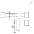
ここで、本主題の例による電力システム100aを示す図1Aを参照する。電力システム100aは、1つまたは複数の電源102を含み得る。一例として、電力システム100aは、PV電力システムであってもよく、電源102は、PV発電機/PVモジュールであってもよい。電源は、本明細書ではPV発電機/PVモジュールの文脈で説明されているが、電源という用語は、他の種類の電源、例えば、風力タービン、水力タービン、燃料電池、電池などを含み得ることが理解されよう。
Here, reference is made to FIG. 1A showing an
電源102は、1つまたは複数のシステム電源装置104に接続してもよい。電源は、単一の電源または複数の電源(例えば、直列および/または並列に接続されている)であってもよい。
The
システム電源装置104は、例えば、DC−DCコンバータ(例えば、降圧コンバータ、昇圧コンバータ、降圧/昇圧コンバータ、降圧+昇圧コンバータ、フライバックコンバータやフォワードコンバータなどの絶縁コンバータ)、DC−ACコンバータ/インバータ、マイクロインバータなどの1つまたは複数であってもよい。システム電源装置104は、1つまたは複数の相のインバータ(例えば、単相インバータ、二相/分相インバータ、および/または三相インバータなど)であり、簡単にするために本明細書に示されていないライン/相を含み得る。
The system
システム電源装置104は、1つまたは複数の負荷106に接続してもよい。1つまたは複数の負荷は、例えば、電力網(例えば、AC電力網)、蓄電装置(例えば、電池)、抵抗素子(例えば、抵抗器)などを含み得る。
The
システム電源装置104は、1つまたは複数の放電回路108に接続してもよい。
The
システム電源装置104は、システム電源装置104を電力システム100a1つまたは複数の他の要素(電源102、負荷106、放電回路108など)に切り替え可能/反転可能に接続/切断するように構成される1つまたは複数のスイッチ(例えば、図9に図示)を含み得る。1つまたは複数のスイッチは、例えば、MOSFET、バイポーラ接合トランジスタ(BJT)、ソレノイドスイッチ、リレースイッチ、コンタクタスイッチなどのうちの1つまたは複数を含み得る。
The
システム電源装置104は、1つまたは複数のコンデンサCを含み得る。例えば、比較的大きなコンデンサ(例えば、約1mF/1,000uFから約10mF/10,000uF、例えば、約5mF/5,000uF)である。1つまたは複数のコンデンサは、比較的大きな電位に対応する比較的大きな電荷を蓄積し得る。この比較的大きな電位は、電力システムに近づく必要があるかもしれない人々に潜在的な危険をもたらす可能性がある。
The
例えば、特定の安全状況では、システム電源装置104(例えば、インバータ)を遮断すること、および/またはシステム電源装置104を1つまたは複数の負荷106から切断する必要がある場合がある。そのような場合、システム電源装置104(例えば、インバータ)内の比較的大きなコンデンサのために、安全作業者が比較的大きな電位にさらされないことを確実にしたいという要望があるかもしれない。したがって、比較的大きな電圧(例えば、数百または数千ボルト、例えば、約500ボルトまたは約1,000ボルト)を比較的低い電圧/安全閾値電圧(例えば、数十ボルト、例えば、約20ボルトまたは約30ボルト)に比較的短い時間(例えば、数十秒、例えば、約10秒〜約30秒)で放電する(例えば、負荷上で分散/放散する)必要があるかもしれない。
For example, in certain safety situations, it may be necessary to shut down the system power supply 104 (eg, an inverter) and / or disconnect the
別の例として、特定の状況では、保守作業員が電力システムの保守を実行する必要がある場合がある。これらの場合および他の場合には、比較的大きな電圧を比較的短い時間で(例えば、より低い電圧閾値、例えば、30ボルトの安全閾値まで)放電する(例えば、放電負荷に分散/放散する)必要がある場合もあるち。 As another example, in certain situations, a maintenance worker may need to perform maintenance on a power system. In these and other cases, a relatively large voltage is discharged in a relatively short time (eg, to a lower voltage threshold, eg, a safety threshold of 30 volts) (eg, distributed / dissipated to a discharge load). Sometimes you need to.
放電回路108は、放電を実行するための1つまたは複数の標示/信号に応答して、入力電圧を放電する(例えば、コンデンサCによる)ように構成されてもよい。
The
放電を実行するための1つまたは複数の標示は、過電圧、単独運転、シャットダウン、保守、少なくとも1つのスイッチがオフにされたことの標示、少なくとも1つのシステム電源装置104がオフにされたことの標示、ハウジングのカバーのロックが解除されている/取り外されているなどの標示に関連してもよい。
One or more markings for performing discharge are overvoltage, stand-alone operation, shutdown, maintenance, marking that at least one switch has been turned off, and that at least one
シャットダウンに関連する標示には、1つまたは複数のシャットダウン信号が含まれる場合がある。1つまたは複数のシャットダウン信号は、1つまたは複数のセンサ測定値または1つまたは複数の通信信号を含んでもよい。例えば、コントローラに結合された通信デバイスは、通信信号を(例えば、サーバまたは中央制御デバイスから)受信することができ、通信信号を受信すると、コントローラは、放電回路を操作して、入力電圧を放電することができる。別の例として、電圧センサは、入力電圧を継続的に測定し、コントローラに電圧測定値を提供することができる。電圧測定値が閾値を超えている場合、コントローラは放電回路を操作して入力電圧を放電することができる。 The shutdown-related markings may include one or more shutdown signals. The one or more shutdown signals may include one or more sensor measurements or one or more communication signals. For example, a communication device coupled to a controller can receive a communication signal (eg, from a server or central control device), and upon receiving the communication signal, the controller operates a discharge circuit to discharge the input voltage. can do. As another example, the voltage sensor can continuously measure the input voltage and provide the controller with a voltage reading. If the measured voltage exceeds the threshold, the controller can operate the discharge circuit to discharge the input voltage.
少なくとも1つのスイッチがオフにされたことの標示は、少なくとも1つのDCスイッチがオフにされたことの標示、および/または少なくとも1つのACスイッチがオフにされたことの標示であってもよい。DCスイッチは、DC電源に接続されているラインに接続されているスイッチの場合がある。一部の例では、DCスイッチは、回路(例えば、電力システムの1つまたは複数の要素に含まれる回路、例えば、システム電源装置104に関連する回路)をDC電源またはDC負荷に接続するように構成されたスイッチであってもよい。ACスイッチは、AC電源またはAC負荷(例えば、電力網)に接続されているラインに接続されているスイッチであってもよい。 The indication that at least one switch has been turned off may be an indication that at least one DC switch has been turned off and / or that at least one AC switch has been turned off. The DC switch may be a switch connected to a line connected to a DC power supply. In some examples, the DC switch connects a circuit (eg, a circuit contained in one or more elements of a power system, eg, a circuit associated with the system power supply 104) to a DC power supply or DC load. It may be a configured switch. The AC switch may be a switch connected to a line connected to an AC power source or an AC load (eg, power grid).
放電回路108は、1つまたは複数の入力および1つまたは複数の出力(例えば、図4に図示されている1つまたは複数の入力端子Yおよび1つまたは複数の出力端子Z、および/または1つまたは複数の入力端子Wおよび1つまたは複数の出力端子X。簡略化のため、他の図では入力端子と出力端子の図を省略している場合がある)。
The
放電回路108は、放電される要素を横切って(例えば、システム電源装置104の1つまたは複数のコンデンサCを横切って)接続されてもよい。これはすべての図に当てはまる可能性があるが、簡単にするために図全体に示されていない。放電回路108が放電される要素を放電するために、放電回路108の他の構成も可能であってもよい。
The
放電回路は、アース電位/地電位に接続できる。アース電位/地電位は、(実際のアース/地面に電気的に接続されているのではなく)仮想/ローカルアース電位/地電位であってもよい。放電の閾値は、実際のアース/地電位に対するフローティング電圧である電圧であってもよい。放電の閾値は、電力システム(例えば、システム電源装置104)の1つまたは複数の要素に関連する電圧であってもよい。 The discharge circuit can be connected to the earth potential / telluric potential. The earth potential / earth potential may be a virtual / local earth potential / earth potential (rather than being electrically connected to the actual earth / ground). The discharge threshold may be a voltage that is a floating voltage relative to the actual ground / earth potential. The discharge threshold may be the voltage associated with one or more elements of the power system (eg, system power supply 104).
一部の例では、入力電荷をシステム電源装置104の1つまたは複数の内部蓄電コンデンサCに移動させることによって、入力電圧を放電することができる。電荷の移動は、例えば、ほぼ一定の電流値であってもよい。このように、規制で許可されている場合、過剰な入力電圧を将来の使用のために危険ではない方法で蓄積することができ、放散する必要はない。
In some examples, the input voltage can be discharged by transferring the input charge to one or more internal storage capacitors C in the
放電回路108の標示/制御は、1つまたは複数のコントローラ112によって容易にされてもよい。1つまたは複数のコントローラ112は、電力システム100a(例えば、システム電源装置104、および/または放電回路108)の1つまたは複数の他の要素の一部であってもよい。1つまたは複数のコントローラ112は、代替的におよび/または追加的に、電力システム100aの別個の外部要素(例えば、システム電源装置104の外部および/または放電回路108の外部)であってもよい。上記のように、1つまたは複数のコントローラは、デジタルコントローラおよび/またはアナログコントローラを含み得る。1つまたは複数のコントローラ112は、電力システム100a内の1つまたは複数のスイッチを制御するように構成されてもよい。1つまたは複数のコントローラ112は、入力電圧を放電するように放電回路108を動作させるように構成されてもよい。1つまたは複数のコントローラ112は、放電回路108の出力電圧を調整するように構成されてもよい。1つまたは複数のコントローラ112は、出力電圧を(例えば、入力電圧を放電する少なくとも1つのフェーズまたは期間に対して)ほぼ一定の値に調整するように構成されてもよい。1つまたは複数のコントローラ112は、放電回路108の出力電流を(例えば、少なくとも1つの放電フェーズに対して)ほぼ一定の電流値に調整するように構成されてもよい。1つまたは複数のコントローラ112は、放電回路108の出力電力を、放電の少なくとも1つのフェーズに対してほぼ一定の電力値に調整するように構成されてもよい。
The marking / control of the
電力システム100aは、複数のコントローラ(図示せず)を含み得、それらのコントローラのうちの1つまたは複数は、マスターコントローラ/中央コントローラ112として指定されてもよい。場合によっては、中央コントローラ112がマスター制御装置であってもよい。一部の例では、各電源装置110は、外部中央コントローラの有無にかかわらず独自のコントローラを有し得、それらの内部コントローラのうちの1つまたは複数がマスターコントローラとして指定されてもよい。図1Aは、システム電源装置104、放電回路108の外部の中央コントローラとしてのコントローラ112を示している。図1Dは、電源装置110の外部の中央コントローラとしてのコントローラ112を示している。場合によっては、1つまたは複数のコントローラが、電源装置110、システム電源装置104、および/または放電回路118に含まれ得、1つまたは複数の内部コントローラが、中央コントローラ/マスターコントローラとして指定されてもよい。一例として、中央コントローラ112の機能は、電源装置110およびシステム電源装置104の一部として含まれる1つまたは複数のコントローラに含まれ得る。例えば、電源装置110(図1E)は、複数のコントローラを有し得、それらのコントローラのうちの1つまたは複数は、1つまたは複数の他のコントローラに命令/標示/信号を提供するマスターコントローラとして指定されてもよい。
The
電力システム100aの1つまたは複数のコントローラ112は、電力システムの1つまたは複数の他の要素に、および/または電力システムの1つまたは複数の他の要素から、信号/命令/標示/コマンドとして命令を受信および/または送信するように構成されてもよい。上記のように、1つまたは複数のコントローラは、データにアクセスし、決定/計算/算出を行うように構成された1つまたは複数のプロセッサ/処理回路およびメモリを含み得る。
One or
簡単にするために、コントローラ112と電力システム100aの他の要素(例えば、システム電源装置104、放電回路104、1つまたは複数のセンサ[図示せず]など)との間の接続は、図1には示されていない。一部の例では、電源装置110、システム電源装置104、放電回路108、および/または1つまたは複数のセンサが、1つまたは複数のコントローラ112に通信可能および/または動作可能に接続されてもよいことが理解されよう。例えば、1つまたは複数のセンサは、コントローラ112にデータを提供してもよい。
For simplicity, the connection between the
1つまたは複数のセンサは、電力システム100aに関連する1つまたは複数のパラメータ/パラメータデータを取得するように構成されてもよい。この1つまたは複数のパラメータは、例えば、電流、電圧、電力などの電気的パラメータであってもよい。
The one or more sensors may be configured to acquire one or more parameters / parameter data associated with the
放電回路108および/または1つまたは複数のコントローラ112は、放電回路108の放電を制御するように構成されてもよい。例えば、放電回路108および/または1つまたは複数のコントローラ112は、(例えば、入力に基づいて)出力/放電電力/電圧/電流を制御するように構成されてもよい。放電回路108および/または1つまたは複数のコントローラ112は、放電回路108の出力で出力電力/電圧/電流を制御するように構成され得、その結果、比較的または実質的に一定の放電電力/電圧/電流値が存在する。例えば、コンデンサCの両端の電圧値は、(例えば、コントローラ112によって)監視されてもよい。コントローラ112が、監視された電圧が閾値を超えると決定した場合、コントローラ112は、放電回路108を制御して放電を実行し、コンデンサCの両端の電圧値を低減することができる。放電回路108はまた、(例えば、特定の時間閾値/時間範囲、例えば、約10秒、約20秒、または約30秒、に従って)比較的迅速な放電を実行するように構成されてもよい。
The
放電回路108は、放電を制御するのを助けるために、1つまたは複数の電源装置(例えば、コンバータ、DC−DCコンバータなど)を含み得る。
The
放電回路108は、システム電源装置104の内部(例えば、その一部または接続されている)または外部であってもよい。
The
放電回路108および/または1つまたは複数のコントローラ112は、一定または非一定の放電が存在するように放電を制御/調整するように構成されてもよい。例えば、1つまたは複数のコントローラ112は、放電回路108を動作させて、放電電力が増加(例えば、上向きに傾斜した線形放電電力および/または上向きに傾斜した指数放電電力)するように(例えば、放電電流を増加させることによって)放電を加速させるように、および/または放電電力が減少(例えば、下向きに傾斜した線形放電電力および/または下向きに傾斜した指数放電電力)するように放電を提供するように構成されてもよい。一例として、放電回路は、線形負荷および/または非線形負荷と一緒に放電を実行するように構成されてもよい。
The
放電回路108は、システム電源装置の一部または外部のいずれかである1つまたは複数の電力コンバータ(例えば、1つまたは複数のDC−ACコンバータ、DC−DCコンバータなど)を含み得る。
The
図1Bは、本主題の例による電力システム100bを示している。電力システム100bは、電力システム100aと同様であってもよく、直列ストリング接続で接続された複数の電源102を含むことができる。図1Bは3つの電源102を示しているが、任意の適切な数の電源102を直列ストリング接続で接続することができる。
FIG. 1B shows a
図1Cは、本主題の例による電力システム100cを示している。電力システム100cは、電力システム100a/100bと同様であってもよく、電源102の複数のストリングを含み得る。複数のストリングは、システム電源装置104に並列に接続することができる。図1Cは2つのストリングを示しているが、任意の適切な数のストリングをシステム電源装置104に並列に接続することができる。
FIG. 1C shows a
あるいは、電力システム100cは、直列および/または並列接続の他の組み合わせを含み得る。
Alternatively, the
図1Dは、本主題の例による電力システム100dを示している。電力システム100dは、電力システム100a/100b/100cと同様であってもよい。電源102は、1つまたは複数の電源装置110を含むか、またはそれらに接続することができる。電源装置110は、例えば、DC−DCコンバータ(例えば、降圧コンバータ、昇圧コンバータ、降圧/昇圧コンバータ、降圧+昇圧コンバータ、絶縁コンバータ、フライバックコンバータ、フォワードコンバータなど)、DC−ACコンバータ/インバータ、マイクロインバータなどの1つまたは複数であってもよい。
FIG. 1D shows a
図1Eは、本主題の例による電力システム100eを示している。電力システム100eは、電力システム100a/100b/100c/100dと同様であってもよく、直列ストリング接続で接続されたそれぞれの電源装置110を備えた複数の電源102を含むことができる。図1Eは、それぞれの電源装置110を備えた3つの電源102を示しているが、それぞれの電源装置110を備えた任意の適切な数の電源102を、直列ストリング接続で接続することができる。
FIG. 1E shows a
図1Fは、本主題の例による電力システム100fを示している。電力システム100fは、電力システム100a/100b/100c/100d/100eと同様であってもよく、それぞれの電源装置110を備えた複数の電源102ストリングを含むことができる。複数のストリングは、システム電源装置104に並列に接続することができる。図1Fは、それぞれの電源装置110を備えた2つの電源102のストリングを示しているが、それぞれの電源装置110を備えた任意の適切な数の電源102のストリングを、システム電源装置104に並列に接続することができる。
FIG. 1F shows a
あるいは、電力システム100fは、電源102および電源装置110の直列および/または並列接続の他の組み合わせを含み得る。
Alternatively, the
図1Gは、本主題の例による電力システム100gを示している。電力システム100gは、電力システム100a/100b/100c/100d/100e/100fと同様であってもよいし、それぞれの放電回路108を備えた複数のシステム電源装置104を含み得る。一部の例では、単一の放電回路108は、複数のシステム電源装置104を動作させて放電を提供するように構成されてもよい。複数のシステム電源装置104は、電源102に並列に接続することができる。図1Gの例では、各システム電源装置104は、それぞれの負荷106に接続されてもよい。図1Gは2つのシステム電源装置104を示しているが、任意の適切な数のシステム電源装置104を電源102に並列に接続することができる。
FIG. 1G shows 100 g of a power system according to an example of this subject. The
複数のシステム電源装置104(例えば、DC−ACコンバータ/インバータ)を電源102の出力(例えば、インバータの「DC側」)に並列に接続することは、複数のシステム電源装置104の複合放電を助けることができる(例えば、切断の有無にかかわらず、すなわち、システム電源装置104は、実質的に同時に、または互いに別々に、放電を実行するように構成されてもよく、例えば、切断なしの場合、1つのシステム電源装置104の放電が、別のシステム電源装置104の放電を引き起こしてもよく[例えば、システム電源装置104が互いに同期しており、システム電源装置104が放電中に入力容量および電圧を共有している場合、それらが互いに切断するように構成されていないため、システム電源装置104の1つの放電が結果として他のシステム電源装置104の放電を生じさせる]、または、切断ありの場合、1つのシステム電源装置104の放電が、別のシステム電源装置104の放電を引き起こさなくてもよい[例えば、システム電源装置104が必ずしも互いに同期されておらず、システム電源装置104が別々に放電するように構成されている場合、放電システム電源装置は、放電を開始する前に他のシステム電源装置から切断するように構成されてもよいので、1つのシステム電源装置104の放電が、別のシステム電源装置104の放電をもたらさない可能性がある])。例えば、1つのシステム電源装置104の放電/切断は、1つのシステム電源装置104の放電/切断に関連する標示に基づいて決定することができる。切断は、電力システムの1つまたは複数の他の要素(例えば、電源102、負荷106、電源装置110など)からの1つのシステム電源装置104の切断を含み得る。
Connecting a plurality of system power supplies 104 (eg, a DC-AC converter / inverter) in parallel to the output of the power supply 102 (eg, the "DC side" of the inverter) aids in the combined discharge of the plurality of system power supplies 104. It can be configured (eg, with or without disconnection, i.e., the
あるいは、電力システム100gは、電源102、電源装置110、システム電源装置104、および負荷106の直列および/または並列接続の他の組み合わせを含み得る。
Alternatively, the
図1Hは、本主題の例による電力システム100hを示している。電力システム100hは、電力システム100a/100b/100c/100d/100e/100g/100hと同様であってもよいし、それぞれの放電回路108を備えた複数のシステム電源装置104を含み得る。一部の例では、単一の放電回路108が、複数のシステム電源装置104を動作させて放電を提供するように構成されてもよい。複数のシステム電源装置104は、負荷106に並列に接続することができる。図1Hの例では、各システム電源装置104は、それぞれの電源102に接続されてもよい。図1Hは2つのシステム電源装置104を示しているが、任意の適切な数のシステム電源装置104を負荷106に並列に接続することができる。
FIG. 1H shows a
複数のシステム電源装置104(例えば、DC−ACコンバータ/インバータ)を負荷106への入力(例えば、インバータの「AC側」)で並列に接続することは、複数のシステム電源装置104の開始を助けることができる(例えば、複数のシステム電源装置104が「ウェイクアップ」動作モードで動作/動作し始めるとき)。
Connecting multiple system power supplies 104 (eg, DC-AC converter / inverter) in parallel at the input to load 106 (eg, "AC side" of the inverter) helps start multiple system power supplies 104. It can (eg, when multiple
あるいは、電力システム100hは、電源102、電源装置110、システム電源装置104、および負荷106の直列および/または並列接続の他の組み合わせを含み得る。
Alternatively, the
図2〜11に示される様々な電力システム100A〜100Kに関する以下の説明は、図1A〜1Hを参照して上記で説明された異なる電力システム100a〜100hを含み得る。図2〜11の様々な電力システム100A〜100Kの図は、簡単にするために、単一の電源102を示しており、電源装置110を示していない。上記のように、場合によっては、1つまたは複数の電源102および1つまたは複数の電源装置110を、組み合わされた機能を備えた単一のユニットに組み合わせることができる。
The following description of the
図2は、本主題の例による電力システム100Aを示している。電力システム100Aは、放電回路108Aを含む。放電回路108Aは、少なくとも1つの抵抗器Rおよび少なくとも1つのスイッチQを含み得る。例えば、コントローラ112が、コンデンサCの両端の電圧が閾値を超えると決定した場合、コントローラ112は、スイッチQをオンにする(例えば、閉じる)ことで、放電回路108が電圧を放電できるようにする。放電中、コントローラ112は、コンデンサCの両端の電圧を監視し続け、電圧がもはや閾値を超えていないことを決定することができる。次に、コントローラ112は、スイッチQをオフにする(例えば、開く)ことで、放電を終了することができる。したがって、コンデンサCの両端の電圧は、閾値未満に維持されてもよい。一例として、スイッチQは、放電回路108が放電を実行する放電モードである間、動作可能(例えば、オン、例えば、閉状態)であり、放電回路108が放電を実行する放電モードにない間、非動作(例えば、オフ、例えば、開状態)であるように構成されてもよい。例えば、スイッチQは、(例えば、放電を実行すべきかどうかの1つまたは複数の決定に基づいて)放電が必要な場合、オンになり、(例えば、放電が実行された/完了したという1つまたは複数の決定に基づいて)放電が必要でない場合、オフになり得る。
FIG. 2 shows a
スイッチQは、例えば、FET、MOSFET、BJT、絶縁ゲートバイポーラトランジスタ(IGBT)などの1つまたは複数であってもよい。 The switch Q may be one or more, for example, a FET, a MOSFET, a BJT, an insulated gate bipolar transistor (IGBT), or the like.
スイッチQは、図2にMOSFETとして示されている。 The switch Q is shown as a MOSFET in FIG.
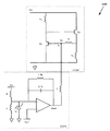
図3は、本主題の例による電力システム100Bを示している。電力システム100Bは、放電回路108Bを含み得る。放電回路108Bは、少なくとも1つの抵抗器R、少なくとも1つのスイッチQ、および少なくとも1つの比較器Mを含み得る。比較器Mは、放電を制御し、放電回路108Bを流れる実質的に一定の放電電流を保証するように構成されてもよい。上記の通り、スイッチQは、放電回路108が放電を実行する放電モードである間、動作可能(例えば、オン、例えば、閉状態)であり、放電回路108が放電を実行する放電モードにない間、非動作(例えば、オフ、例えば、開状態)であるように構成されてもよい。例えば、スイッチQは、(例えば、放電を実行すべきかどうかの1つまたは複数の決定に基づいて)放電が必要な場合、オンになり、(例えば、放電が実行された/完了したという1つまたは複数の決定に基づいて)放電が必要でない場合、オフになり得る。
FIG. 3 shows a
スイッチQは、図3にBJTとして示されている。 The switch Q is shown as BJT in FIG.
図4は、本主題の例による電力システム100Cを示している。電力システム100Cは、放電回路108Cを含み得る。放電回路108Cは、少なくとも1つの抵抗器R、少なくとも1つのスイッチQ、および少なくとも1つの電源装置400を含み得る。
FIG. 4 shows a
放電回路108Cは、少なくとも1つの放電経路を含み得る。少なくとも1つの放電経路は、電源装置400に接続されてもよい。少なくとも1つの放電経路は、少なくとも1つの放電抵抗器Rおよび少なくとも1つのスイッチQを含み得る。上記の通り、スイッチQは、放電回路108が放電を実行する放電モードである間、動作可能(例えば、オン、例えば、閉状態)であり、放電回路108が放電を実行する放電モードにない間、非動作(例えば、オフ、例えば、開状態)であるように構成されてもよい。例えば、スイッチQは、(例えば、放電を実行すべきかどうかの1つまたは複数の決定に基づいて)放電が必要な場合、オンになり、(例えば、放電が実行された/完了したという1つまたは複数の決定に基づいて)放電が必要でない場合、オフになり得る。
The
電源装置400は、例えば、DC−DCコンバータ(例えば、降圧コンバータ、昇圧コンバータ、降圧/昇圧コンバータ、降圧+昇圧コンバータ、絶縁コンバータ、フライバックコンバータ、フォワードコンバータなど)、DC−ACコンバータ/インバータ、マイクロインバータなどの1つまたは複数であってもよい。
The
電源装置400は、1つまたは複数の入力および1つまたは複数の出力(例えば、1つまたは複数の入力端子Wおよび1つまたは複数の出力端子X)を含み得る。
The
電源装置400は、放電専用であってもよい(これについては以下で説明する)。
The
電源装置400は、放電以外の他の機能/動作モードを有し得る(例えば、システム電源装置104内の/のための電力変換)。
The
電源装置400は、補助電力コンバータおよび/または主専用電力コンバータであってもよい。例えば、補助電力コンバータは、主負荷ではない電力システムの1つまたは複数の要素(例えば、電力網ではない電力システムの1つまたは複数の要素、例えば、1つまたは複数の論理回路、1つまたは複数のゲート制御回路、1つまたは複数のコントローラ、1つまたは複数の放電回路など)に電力を供給するように構成された電力コンバータであってもよい。
The
電源装置400は、システム電源装置104の一部であるパワーステージ/パワートレイン(例えば、DC−AC電力コンバータ、またはDC−DC電力コンバータ)として機能し得る(例えば、インバータ)。
The
例えば、電源装置400は、システム電源装置104においてパワーステージ/パワートレイン(例えば、DC−AC電力コンバータ、またはDC−DC電力コンバータ)として機能し、および/または他の機能ではなく、放電専用の専用DC−DC放電コンバータを構成/提供/使用してもよい。
For example, the
例えば、パワーステージ/パワートレインは、電力システムの主負荷(例えば、電力網、1つまたは複数のモータ、1つまたは複数の蓄電装置など)に電力を供給するように構成された電力コンバータであってもよい。 For example, a power stage / power train is a power converter configured to power the main load of a power system (eg, a power grid, one or more motors, one or more power storage devices, etc.). May be good.
放電回路108Cは、複数の電源装置400を含み得る。
The
放電回路108Cはまた、例えば、専用、非専用、補助、主などの異なるタイプの複数の電源装置400を含み得る。
The
放電回路108Cは、少なくとも1つの電源装置400、および他の放電回路(例えば、同時にまたは逐次に動作するように構成された電源装置を含む、または含まない他の放電回路)を使用してもよい。
The
例えば、電力システム/1つまたは複数のコントローラは、放電プロセスの異なる段階/フェーズで異なる放電回路を切り替え/接続するように構成され得、および/または特定の閾値の後に異なる放電回路間で切り替え/接続するように構成されてもよい。異なる段階/フェーズの異なる回路の動作が、電力システム/放電回路の異なる動作モードを構成してもよい。 For example, a power system / one or more controllers may be configured to switch / connect different discharge circuits at different stages / phases of the discharge process, and / or switch between different discharge circuits after a particular threshold. It may be configured to connect. The operation of different circuits in different stages / phases may constitute different modes of operation of the power system / discharge circuit.
例えば、放電回路/電源装置400は、第1の放電フェーズの中に第1のモードで第1の放電回路を用いて(例えば、比較的一定の放電電力/電圧/電流を提供する電源装置を用いて)、特定の閾値に到達するまで(例えば、第1の電力/電圧値から第2の電力/電圧値まで)放電を制御し、次に、第2の放電フェーズ中に第2のモードで異なる第2の放電回路を使用して(例えば、比較的線形または指数関数的な放電を提供するスイッチ/トランジスタおよび抵抗器を用いて)、放電を終了(例えば、第2の電力/電圧値から第3の電力/電圧値まで)するように構成されてもよい。
For example, the discharge circuit /
スイッチQはMOSFETとして図4に示されている。 The switch Q is shown as a MOSFET in FIG.
1つまたは複数のコントローラ112は、放電回路/電源装置400の動作に関連する1つまたは複数のパラメータを制御することによって放電を制御するように構成されてもよい。1つまたは複数のコントローラ112によって制御可能であってもよい放電回路/電源装置400の動作に関連する1つまたは複数のパラメータは、例えば、デューティサイクル、周波数、電流、電圧などであってもよい。例えば、コントローラ112は、放電回路/電源装置400の電圧または電流出力(例えば、放電回路/電源装置400の端子Xでの電圧または電流)を、実質的に一定の値に制御し得、したがって、放電回路108Cの放電電圧または電流を実質的に一定の値に維持し得る。一例として、コントローラ112は、1つまたは複数のスイッチ(例えば、スイッチQおよび/または電源装置400の一部である1つまたは複数のスイッチ)のデューティサイクルを制御することによって、放電回路/電源装置400の電圧または電流出力を制御するように構成されてもよい。1つまたは複数のスイッチがオンおよびオフされる周波数を制御することは、放電回路/電源装置400の出力に影響を及ぼし得る。これは、放電回路/電源装置400の出力を制御するために行われ得る(例えば、放電回路108Cの放電電圧または電流を実質的に一定の値に維持するために)。別の例として、コントローラ112は、スイッチを部分的にのみオン状態に回すことによってスイッチを制御することができ、その結果、スイッチを完全にオンにすることによって達成されるよりも大きなスイッチ抵抗およびより遅い放電(より低い電流で)となる。
The one or
図5は、本主題の例による電力システム100Dを示している。電力システム100Dは、放電回路108Dを含む。放電回路108Dは、複数の抵抗器R1、R2、複数のスイッチQ1、Q2、および少なくとも1つの電源装置400を含み得る。上記の通り、スイッチQ1、Q2は、放電回路108が放電を実行する放電モードである間、動作可能(例えば、オン、例えば、閉状態)であり、放電回路108が放電を実行する放電モードにない間、非動作(例えば、オフ、例えば、開状態)であるように構成されてもよい。例えば、スイッチQ1、Q2は、(例えば、放電を実行すべきかどうかの1つまたは複数の決定に基づいて)放電が必要な場合、オンになり、(例えば、放電が実行された/完了したという1つまたは複数の決定に基づいて)放電が必要でない場合、オフになり得る。
FIG. 5 shows a power system 100D according to an example of this subject. The power system 100D includes a
スイッチQ1、Q2はMOSFETとして図5に示されている。 Switches Q1 and Q2 are shown as MOSFETs in FIG.
放電回路108Dは、少なくとも2つの放電経路を含み得る。少なくとも2つの放電経路は、電源装置400に接続されてもよい。第1の放電経路は、少なくとも1つの第1の抵抗器R1および少なくとも1つの第1のスイッチQ1を含み得る。少なくとも1つの第1の抵抗器R1および少なくとも1つの第1のスイッチQ1を直列に接続し得る。第2の放電経路は、少なくとも1つの第2の抵抗器R2および少なくとも1つの第2のスイッチQ2を含み得る。少なくとも1つの第2の抵抗器R2および少なくとも1つの第2のスイッチQ2を直列に接続し得る。
The
第1の放電経路は、第2の放電経路と平行であってもよい。少なくとも1つの第1の抵抗器R1および少なくとも1つの第1のスイッチQ1は、少なくとも1つの第2の抵抗器R2および少なくとも1つの第2のスイッチQ2に並列に接続され得る。 The first discharge path may be parallel to the second discharge path. At least one first resistor R1 and at least one first switch Q1 can be connected in parallel to at least one second resistor R2 and at least one second switch Q2.
上記のように、電力システム100Dは、1つまたは複数のセンサ(図示せず)を含み得る。 As mentioned above, the power system 100D may include one or more sensors (not shown).
1つまたは複数のセンサは、電源装置400に関連する(例えば、電源装置の入力に関連する、電源装置の出力に関連するなど)1つまたは複数のパラメータを感知し得る。 One or more sensors may sense one or more parameters associated with the power supply 400 (eg, related to power supply inputs, related to power supply outputs, etc.).
放電回路および/または放電回路を動作させるように構成されたコントローラは、放電/動作の異なるフェーズ/段階に対応する異なるモードで構成されてもよい。放電回路および/または放電回路を動作させるように構成されたコントローラは、異なる閾値に応答して/基づいて(例えば、1つまたは複数の感知されたパラメータ、例えば、電源装置400の出力における感知された電圧に関連して、または経過時間に応じて)モードを切り替えるように構成されてもよい。 The discharge circuit and / or the controller configured to operate the discharge circuit may be configured in different modes corresponding to different phases / stages of discharge / operation. The discharge circuit and / or the controller configured to operate the discharge circuit is sensed in response to / based on different thresholds (eg, one or more sensed parameters, eg, the output of the power supply 400). It may be configured to switch modes in relation to the voltage (or depending on the elapsed time).
例えば、放電回路を動作させるように構成されたコントローラは、第1のフェーズ/段階中は第1の放電モードで放電回路を動作させるように構成され得、ここで第1のモードは、第1の放電経路および第2の放電経路の両方を実質的に同時に使用し、第2のフェーズ/段階中は第2の放電モードで動作させるように構成され得、ここで第2のモードは、第2の放電経路は使用せず、第1の放電経路のみを使用する。 For example, a controller configured to operate a discharge circuit may be configured to operate the discharge circuit in a first discharge mode during the first phase / stage, where the first mode is the first. The discharge path and the second discharge path can be configured to be used substantially simultaneously and operated in the second discharge mode during the second phase / stage, where the second mode is the second mode. The second discharge path is not used, only the first discharge path is used.
電力システム/放電回路(例えば、放電回路108D)は、1つまたは複数の追加の放電回路/1つまたは複数の追加の放電経路(例えば、放電回路108A)を含み得る。
The power system / discharge circuit (eg,
追加の放電回路/追加の放電経路は、電力システムの1つまたは複数の要素内にあってもよい(例えば、システム電源装置104において、例えば、電源装置400への入力の前、および/または電源装置400の出力の後に接続される)。
Additional discharge circuits / additional discharge paths may be within one or more elements of the power system (eg, in
追加の放電回路/追加の放電経路は、外部要素であってもよい。 The additional discharge circuit / additional discharge path may be an external element.
追加の放電回路/追加の放電経路は、第1の放電回路と並列に接続され得る。 The additional discharge circuit / additional discharge path may be connected in parallel with the first discharge circuit.
追加の放電回路/追加の放電経路は、第1の放電回路/放電経路よりも高速であってもよい。しかしながら、追加の放電回路/追加の放電経路はまた、状況によっては、第1の放電回路/放電経路よりも潜在的に不安定である可能性があり、例えば、追加の放電回路/追加の放電経路は、比較的短い時間で比較的大量の放電電力/電圧を放電するように構成されてもよい。 The additional discharge circuit / additional discharge path may be faster than the first discharge circuit / discharge path. However, the additional discharge circuit / additional discharge path may also be potentially more unstable than the first discharge circuit / discharge path in some circumstances, eg, additional discharge circuit / additional discharge. The path may be configured to discharge a relatively large amount of discharge power / voltage in a relatively short period of time.
異なる放電回路/放電経路を含む異なる動作モードは、放電/動作の異なるフェーズ/段階の間に(例えば、電源装置400の出力の電圧の、異なる閾値に応答して/基づいて)切り替えることができる。 Different modes of operation, including different discharge circuits / paths, can be switched between different phases / stages of discharge / operation (eg, in response to / based on different thresholds of the output voltage of the power supply 400). ..
例えば、第1の放電フェーズ/段階/期間中に、放電回路を操作するように構成されたコントローラは、第1の回路および第2の回路(または第1の回路のみ)を使用するように構成され得、第2の放電フェーズ/段階/期間中に、放電回路は、第1の回路ではなく、第2の回路のみを使用するように構成され得る(これにより、より高速な放電が可能になり、潜在的に危険な電圧を急速に低減することで安全性が向上する可能性があるが、リスクが高まる可能性があり、これは、第2のフェーズ/段階の入力電力/電圧の量を第1のフェーズ/段階の入力電力/電圧の量よりも少なくすることによって軽減される可能性がある。 For example, a controller configured to operate a discharge circuit during a first discharge phase / stage / period is configured to use a first circuit and a second circuit (or only the first circuit). The discharge circuit may be configured to use only the second circuit, not the first circuit, during the second discharge phase / stage / period (which allows for faster discharges). It can improve safety by rapidly reducing potentially dangerous voltages, but it can also increase risk, which is the amount of input power / voltage in the second phase / stage. May be mitigated by making it less than the amount of input power / voltage in the first phase / stage.
例えば、第1のモード/フェーズ/段階および/または第1の期間では、第1の回路と第2の回路の両方を使用し、第2のモード/フェーズ/段階および/または第2の期間では、第1の回路のみを使用し、第2の回路を使用しない。 For example, in the first mode / phase / stage and / or in the first period, both the first and second circuits are used, and in the second mode / phase / stage and / or in the second period. , Use only the first circuit, not the second circuit.
例えば、第1のモード/フェーズ/段階および/または第1の期間では、第1の回路のみを使用して、第2の回路は使用せず、第2のモード/フェーズ/段階および/または第2の期間では、第1の回路は使用せず、第2の回路のみを使用する。 For example, in the first mode / phase / stage and / or in the first period, only the first circuit is used, the second circuit is not used, and the second mode / phase / stage and / or the first. In the second period, the first circuit is not used and only the second circuit is used.
例えば、第1のモード/フェーズ/段階および/または第1の期間では、第1の回路のみを使用して、第2の回路は使用せず、第2のモード/フェーズ/段階および/または第2の期間では、1の回路と第2の回路の両方を使用する。 For example, in the first mode / phase / stage and / or in the first period, only the first circuit is used, the second circuit is not used, and the second mode / phase / stage and / or the first. In the second period, both the first circuit and the second circuit are used.
例えば、第1のモード/フェーズ/段階および/または第1の期間では、第1の回路のみを使用して、第2の回路は使用せず、第1および第2の経路を使用し、第2のモード/フェーズ/段階および/または第2の期間では、第1の回路のみを使用して、第2の回路は使用せず、第1の経路のみを使用し、第2の経路を使用せず、第3のモード/フェーズ/段階および/または第3の期間では、第1の回路は使用せず、第2の回路のみを使用する。 For example, in the first mode / phase / stage and / or the first period, only the first circuit is used, the second circuit is not used, and the first and second paths are used. In the second mode / phase / stage and / or second period, only the first circuit is used, the second circuit is not used, only the first path is used, and the second path is used. Instead, in the third mode / phase / stage and / or third period, the first circuit is not used and only the second circuit is used.
例えば、第1のモード/フェーズ/段階および/または第1の期間では、第1の回路と第2の回路の両方を使用し、第2のモード/フェーズ/段階および/または第2の期間では、第1の回路と第3の回路の両方を使用して、第2の回路は使用せず、第3のモード/フェーズ/段階および/または第3の期間では、第1の回路のみを使用して、第2の回路と第3の回路を使用しない。 For example, in the first mode / phase / stage and / or in the first period, both the first and second circuits are used, and in the second mode / phase / stage and / or in the second period. , Using both the first and third circuits, no second circuit, only the first circuit in the third mode / phase / stage and / or third period Therefore, the second circuit and the third circuit are not used.
図6は、本主題の例による電力システム100Eを示している。電力システム100Eは、放電回路108Aおよび放電回路108Cを含み得る。放電回路108Aは、システム電源装置104に含まれ得る。放電回路108Aおよび放電回路108Cは、同時におよび/または順番に動作し得る。例えば、第1の放電フェーズおよび第2の放電フェーズの両方において、放電回路108Aおよび放電回路108Cの両方が、動作可能であり、放電を提供するように構成され得る。あるいは、第1の放電フェーズでは、放電回路108Aと放電回路108Cの両方が動作可能であり、放電を提供するように構成され得、第2の放電フェーズでは、放電回路108Aまたは放電回路108Cのみが動作可能であり、提供するように構成され得、他方の放電回路はオフとなり/放電を提供するための動作不能である。または、第1の放電フェーズでは、放電回路108Aまたは放電回路108Cのみが動作可能であり、放電を提供するように構成され得、一方、他方の放電回路はオフとなり/放電を提供するための動作不能であり、第2の放電フェーズでは、放電回路108Aおよび放電回路108Cは両方とも、動作可能であり、放電を提供するように構成され得る。さらにあるいは、第1の放電フェーズでは、放電回路108Aまたは放電回路108Cのいずれかが動作可能であり、放電を提供するように構成され得(例えば、線形放電のみまたは一定放電のみが望まれる場合、および/または直接放電[電源装置の使用を含まない]または制御された変換放電[電源装置の使用を含む]が望ましいとき)、他方の放電回路はオフとなり/放電を提供するための動作不能であり、および第2の放電フェーズでは、他方の放電回路が動作可能であり、放電を提供するように構成され得(例えば、別のタイプの放電、例えば、一定放電または線形放電、および/または制御された変換放電または直接[非制御変換]放電が望ましいとき)、第1の放電フェーズ中に放電を提供するように動作可能であった放電回路が第2の放電フェーズではオフとなり/放電を提供するための動作不能である。一部の例では、他の放電回路(例えば、図3に示される放電回路108B)が、システム電源装置104に含まれ得る。
FIG. 6 shows a power system 100E according to an example of this subject. The power system 100E may include a
放電回路の制御は、アナログおよび/またはデジタルであってもよい(例えば、1つまたは複数のアナログおよび/またはデジタルコントローラ112を使用する)。例えば、アナログコントローラ112は、感知された/取得された電圧値(例えば、コンデンサCの両端の感知された/取得された電圧値、および/またはシステム電源装置104に関連する別の感知された/取得された電圧値)を閾値電圧値と比較することによって放電回路108Aを制御するように構成されてもよく、感知/取得された電圧値が感知/取得された電圧値よりも大きい場合、放電回路108Aは放電モードで動作して放電を実行する。別の例として、コントローラ112は、アナログ信号/標示を使用して動作するように構成されたアナログコントローラ112と、デジタル信号/標示を使用して動作するように構成されたデジタルコントローラ112の両方を含み得る。アナログコントローラ112は、デジタルコントローラ112がアナログコントローラに無効化信号を提供することで「通常オン」であってもよい(例えば、第1の動作モードでの放電を防止する)。デジタルコントローラ112がこの無効化信号を提供できない場合(例えば、デジタルコントローラ112に関連する電圧値が閾値電圧値未満である場合)、アナログコントローラ112(無効化信号がないまま)放電回路108を制御/起動し、第2の動作モード(例えば、放電動作モード)で放電/動作を実行するように構成され得る。
The control of the discharge circuit may be analog and / or digital (eg, using one or more analog and / or digital controllers 112). For example, the
図7は、本主題の例による電力システム100Fを示している。電力システム100Fは、放電回路108Aおよび放電回路108Dを含み得る。放電回路108Aは、システム電源装置104に含まれ得る。放電回路108Aおよび放電回路108Dは、同時におよび/または順番に動作し得る。別の例として、他の放電回路(例えば、放電回路108B)が、システム電源装置104に含まれ得る。放電回路108Aおよび/または放電回路108Dは、複数の放電経路を含むことができ、複数の放電経路のうちのどれが/いくつが放電を実行するためにアクティブ化され/非アクティブ化され/動作するかは、電力システムに関連している1つまたは複数の取得/感知/測定されたパラメータに関連し得る。例えば、第1の放電フェーズにおいて、複数の放電経路は、(例えば、放電回路108Dの放電電圧または電流を実質的に一定の値に維持するのを助けるために)放電を実行するように構成され得、第2の放電フェーズにおいて、(例えば、電圧の変化を感知する1つまたは複数のセンサに応答して/基づいて、例えば、電源装置400に関連する入力電圧および/または出力電圧の減少)、(例えば、放電回路108Dの放電電圧または電流を実質的に一定の値に維持するのを助けるため、または放電回路108Aを使用して線形放電および/または直接放電のみを提供するため)単一の放電経路/より少ない放電経路が放電を実行するように構成され得、第1の放電フェーズでアクティブだった他方の放電経路(複数可)は、第2の放電フェーズでは放電を提供するための動作不能である。
FIG. 7 shows a
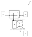
図8は、本主題の例による電力システム100Gを示している。電力システム100Gは、放電回路108Aおよび放電回路108Dを含む。放電回路108Aおよび放電回路108Dは、両方ともシステム電源装置104に含まれ得る。放電回路108Aおよび放電回路108Dは、同時におよび/または順番に動作し得る。別の例として、他の放電回路(例えば、放電回路108B)が、システム電源装置104に含まれ得る。
FIG. 8 shows a
図8の例では、放電回路108Dの一部であってもよい電源装置400は、システム電源装置104(例えば、インバータ)の一部であるパワーステージ/パワートレイン(例えば、DC−ACコンバータまたはDC−DCコンバータ)であってもよい。
In the example of FIG. 8, the
システム電源装置104は、システム電源装置104を他の要素(例えば、電力システム100の電気要素、例えば、電源102、電源装置110、負荷106など)に接続/切断するための1つまたは複数のスイッチを含み得る。システム電源装置104は、システム電源装置104を電源102/電源装置110などのDC要素に接続/切断するための1つまたは複数のDCスイッチを含み得る(例えば、システム電源装置104の「DC側」の1つまたは複数のスイッチ、例として、例えば、図9に示されているS_DC1、S_DC2)。システム電源装置104は、システム電源装置104を負荷106などのAC要素に接続/切断するための1つまたは複数のACスイッチを含み得る(例えば、システム電源装置104の「AC側」にある1つまたは複数のスイッチ、例えば、スイッチS_AC1、S_AC2)。
The
図9は、本主題の例による電力システム100Hを示している。電力システム100Hは、放電回路108Aおよび放電回路108Dを含み得る。放電回路108Aおよび放電回路108Dは、両方ともシステム電源装置104に含まれ得る。放電回路108Aおよび放電回路108Dは、同時におよび/または順番に動作し得る。別の例として、他の放電回路(例えば、放電回路108B)が、システム電源装置104に含まれ得る。
FIG. 9 shows a power system 100H according to an example of this subject. The power system 100H may include a
上記のように、放電を実行するための1つまたは複数の標示は、少なくとも1つのDCスイッチがオフにされたという標示、および/または少なくとも1つのACスイッチがオフにされたという標示に関連し得る。 As mentioned above, one or more markings for performing a discharge relate to markings that at least one DC switch has been turned off and / or that at least one AC switch has been turned off. obtain.
DCスイッチがオフにされたという標示は、システム電源装置104を電源102に接続するスイッチS_DC1、S_DC2の作動に関連し得る(例えば、スイッチS_DC1、S_DC2がオフにされ、電源102からシステム電源装置104が切断されたという標示)。一部の例では、DCスイッチ(例えば、スイッチS_DC1またはS_DC2)がオフにされると、センサ(例えば、電流センサ)は、電源102とシステム電源装置104との間に電流がほとんどまたはまったく流れないことを検出し得る。したがって、センサは、DCスイッチがオフにされたという標示を提供し得る。他の場合、センサは、1つまたは複数の他のセンサ、例えば、電圧センサ、電力センサ、近接センサなどであり得、これらは、DCスイッチがオフにされたときを検出し(例えば、電圧がない/少ないことを感知する、電力がない/少ないことを感知する、スイッチの一部が物理的に動かされたことを感知するなど)、DCスイッチがオフにされたという標示を提供するように構成される。
The indication that the DC switch has been turned off may be related to the operation of switches S_DC1 and S_DC2 that connect the
ACスイッチがオフにされたという標示は、システム電源装置104を負荷106に接続するスイッチS_AC1、S_AC2の作動に関連し得る(例えば、スイッチS_AC1、S_AC2がオフにされ、負荷106からシステム電源装置104が切断されたという標示)。一部の例では、1つまたは複数のセンサは、ACスイッチがオフにされたことを検出し、ACスイッチがオフにされたという標示を提供するように構成されてもよい。
The indication that the AC switch has been turned off may be related to the operation of switches S_AC1 and S_AC2 that connect the
電源装置400は、フルブリッジ回路として示されている。電源装置400/システム電源装置104は、4つのスイッチQおよび1つまたは複数のインダクタL1、L2(例えば、変圧器の1つまたは複数のインダクタ)を含み得る。
The
上記のように、場合によっては、コントローラ112は、デジタルコントローラ112であってもよい。放電回路108Aおよび/または放電回路108Dは、1つまたは複数の非線形放電要素/放電負荷を含み得る(例えば、放電に使用される電気負荷/電気要素。例えば、放電要素/放電負荷は抵抗器ではない場合がある。放電要素/放電負荷は、他の適切な負荷および/または制御された負荷であってもよい)。上記のように、コントローラ112/放電回路108は、放電モード/放電モードの段階で動作するときに、放電電力の一定または線形または指数関数的な下降がないように、放電中に動作するように構成されてもよい。例えば、コントローラ112/放電回路108は、放電モードで動作するときに放電電力の線形または指数関数的な上昇があるように、放電中に動作するように構成されてもよい(すなわち、放電は、コントローラ112/放電回路108/電源装置400によって制御可能であってもよい)。一例として、放電モードの第1の段階で動作するときに放電電力の線形または指数関数的な上昇があってもよいし、放電モードの第2の段階で動作するときに一定の放電電力および/または放電電力の線形または指数関数的な下降があってもよい。
As described above, in some cases, the
図10は、本主題の例による電力システム100Jを示している。電力システム100Jは、放電回路108Aおよび放電回路108Dを含み得る。放電回路108Aおよび放電回路108Dは、両方ともシステム電源装置104の外部にあってもよい。放電回路108Aおよび放電回路108Dは、同時におよび/または順番に動作し得る。放電回路108Aおよび放電回路108Dは、並列に接続することができる。別の例として、他の放電回路(例えば、放電回路108A、108B)が、システム電源装置104に含まれ得る。
FIG. 10 shows a
図11は、本主題の例による電力システム100Kを示している。電力システム100Kは、放電回路108Eを含み得る。放電回路108Eは、システム電源装置104の外部にあってもよい。放電回路108Eは、放電回路108Aおよび放電回路108Dを含み得る。放電回路108Aおよび放電回路108Dは、同時におよび/または順番に動作し得る。放電回路108Aおよび放電回路108Dは、並列に接続することができる。別の例として、他の放電回路(例えば、放電回路108B、108C)が、放電回路108Eおよび/またはシステム電源装置104に含まれ得る。
FIG. 11 shows a
図12は、本主題の例によるグラフ1200、1202、1204を示している。グラフ1200は、放電電力、放電中の放電回路の一部の例の入力および/または出力での入力および/または出力電力(例えば、電力を提供または受け取る放電回路に接続された負荷[例えば、コンデンサCおよび/または抵抗器R]に関連する電力)を表すグラフである。グラフ1202は、放電電圧、放電中の放電回路の一部の例の入力および/または出力での入力および/または出力電圧(例えば、電圧を供給または受け取る放電回路に接続された負荷[例えば、コンデンサCおよび/または抵抗器R]に関連する電圧)を表すグラフである。グラフ1204は、放電電流、放電中の放電回路の一部の例の入力および/または出力での入力および/または出力電流(例えば、電流を提供または受け取る/電流が流れる放電回路に接続された負荷[例えば、コンデンサCおよび/または抵抗器R]に関連する電流)を表すグラフである。放電回路108A(図2)を使用すると、グラフ1200に示されるように、電力の指数関数的放電をもたらす可能性がある。放電回路108Aを使用すると、それぞれグラフ1202および1204に示されるように、電圧の指数関数的放電および放電回路108Aを通って流れる指数関数的電流も生じ得る。例えば、グラフ1200、1202、1204のうちの1つまたは複数は、放電回路108A(図2)の端子Yでの放電電力/電圧/電流(例えば、放電中のコンデンサCおよび/または抵抗器Rに関連する電力/電圧/電流)を例示し得る。
FIG. 12 shows
放電回路108Aの抵抗器RおよびスイッチQは、比較的速い放電中に比較的大きな放電電力/電圧/電流に耐えられる必要があるため、電力の指数関数的放電が問題となり得る。例えば、トランジスタを備えた抵抗器である放電回路を使用すると、指数関数的な電圧散逸、指数関数的な電流、および指数関数的な電力が発生する可能性がある。放電の開始時に、比較的大きな電力が存在する可能性があり、これには、比較的大きな電力(例えば、約160w)に耐えることができる比較的大きな抵抗器が必要となる可能性がある。比較的大きな抵抗器の要件は極めて高くなり得る。
Since the resistor R and the switch Q of the
図13は、本主題の例によるグラフ1300、1302、1304を示している。グラフ1300は、放電電力、放電中の放電回路の一部の例の入力および/または出力での入力および/または出力電力(例えば、電力を提供または受け取る放電回路に接続された負荷[例えば、コンデンサCおよび/または抵抗器R]に関連する電力)を表すグラフである。グラフ1302は、放電電圧、放電中の放電回路の一部の例の入力および/または出力での入力および/または出力電圧(例えば、電圧を供給または受け取る放電回路に接続された負荷[例えば、コンデンサCおよび/または抵抗器R]に関連する電圧)を表すグラフである。グラフ1204は、放電電流、放電中の放電回路の一部の例の入力および/または出力での入力および/または出力電流(例えば、電流を提供または受け取る/電流が流れる放電回路に接続された負荷[例えば、コンデンサCおよび/または抵抗器R]に関連する電流)を表すグラフである。放電回路108B(図3)を使用すると、グラフ1300に示されるように、電力の線形放電をもたらす可能性がある。放電回路108Bを使用すると、それぞれグラフ1302および1304に示されるように、電圧の線形放電および放電回路108Bを流れる比較的一定の電流も生じ得る。比較器Mおよび/またはコントローラ112は、放電電流Iが比較的一定に保たれるように放電を制御するように構成されてもよい。基準電圧Vrefを比較器Mへの入力として使用して、放電を制御し、ほぼ比較的一定の出力電流値を確保してもよい。出力電圧は(例えば、1つまたは複数のセンサによって)感知され得、感知された出力電圧は、放電を制御する(例えば、スイッチQの速度を制御する)ために、基準電圧Vrefと比較されるフィードバックとして使用されてもよい。例えば、グラフ1300、1302、1304のうちの1つまたは複数は、放電回路108B(図3)の端子Yでの放電電力/電圧/電流(例えば、放電中のコンデンサCおよび/または抵抗器Rに関連する電力/電圧/電流)を例示し得る。
FIG. 13 shows
放電回路108BのスイッチQは、比較的速い放電中に比較的大きな放電電力/電圧/電流に耐えられる必要があるため、電力の線形放電が問題となり得る。例えば、線形放電が使用される場合、物理的効果(例えば、スピリト効果)により、スイッチQが誤動作、燃焼、および/または爆発する可能性がある。 Since the switch Q of the discharge circuit 108B needs to withstand a relatively large discharge power / voltage / current during a relatively fast discharge, linear discharge of power can be a problem. For example, when a linear discharge is used, physical effects (eg, spirit effects) can cause the switch Q to malfunction, burn, and / or explode.
例えば、比較的小さい抵抗器を備えたトランジスタ(例えば、BJT)を含む放電回路を使用して、放電を制御することができ、その結果、線形の電圧散逸、一定電流、および線形電力を取得する。放電中、スピリト効果(例えば、トランジスタ内の比較的大きな電流による)は、トランジスタの材料および/または要素を加熱し得る。トランジスタは十分な熱放散をするように設計されていない可能性がある。例えば、熱は、トランジスタの側面ではなく、トランジスタの熱分散器の中心に向けて集中し得、これによってトランジスタが燃焼および/または爆発する可能性がある。これは、非専用回路が放電回路として使用される場合に当てはまる可能性がある。これは、この回路の抵抗器が小さく、放電電流が大きくなる可能性があるためである。この場合、比較的速い放電器が考えられるが、トランジスタはより大きな電流に耐えられない可能性がある。比較的大きな抵抗器を使用すると、電流が少なくなり、放電が比較的遅くなる可能性がある。放電回路108Bを使用して比較的速い時間で比較的大きな電力を放電するとき、放電が適切に制御されない場合、放電はトランジスタ内にスパイクを引き起こし、トランジスタを燃焼、爆発、および/または発火させる可能性がある。一例として、放電を制御するのを助けるように(例えば、放電回路108の放電電圧または電流を実質的に一定の値に維持するのを助けるように)構成された放電回路/1つまたは複数の電源装置400を使用することは、これらの問題を回避するのに役立ち得る。
For example, a discharge circuit containing a transistor with a relatively small resistor (eg, BJT) can be used to control the discharge, resulting in linear voltage dissipation, constant current, and linear power. .. During discharge, the spirit effect (eg, due to the relatively large current in the transistor) can heat the material and / or elements of the transistor. Transistors may not be designed to dissipate sufficient heat. For example, heat can be concentrated towards the center of the transistor's thermal disperser rather than on the sides of the transistor, which can cause the transistor to burn and / or explode. This may be the case when a non-dedicated circuit is used as a discharge circuit. This is because the resistors in this circuit are small and the discharge current can be large. In this case, a relatively fast discharger is conceivable, but the transistor may not be able to withstand the larger current. The use of relatively large resistors can result in low current and relatively slow discharge. When using the discharge circuit 108B to discharge a relatively large amount of power in a relatively fast time, if the discharge is not properly controlled, the discharge can cause spikes in the transistor, causing the transistor to burn, explode, and / or ignite. There is sex. As an example, one or more discharge circuits configured to help control the discharge (eg, to help keep the discharge voltage or current of the
図14は、本主題の例によるグラフ1400、1402、1404を示している。グラフ1400は、放電電力、放電中の放電回路の一部の例の出力での出力電力(例えば、電力を受け取る放電回路に接続された負荷[例えば、抵抗器R]に関連する電力)を表すグラフである。グラフ1402は、放電電圧、放電中の放電回路の一部の例の出力での出力電圧(例えば、電圧を受け取る放電回路に接続された負荷[例えば、抵抗器R]に関連する電圧)を表すグラフである。グラフ1404は、放電電流、放電中の放電回路の一部の例の出力での出力電流(例えば、電流を供給または受け取る/電流が流れる放電回路に接続された負荷[例えば、抵抗器R]に関連する電流)を表すグラフである。電源装置400(例えば、DC−DCコンバータ)と共に放電回路108C(図4)を使用すると、グラフ1400に示されるように、比較的一定の電力の放電をもたらす可能性がある。放電回路108Cを使用すると、それぞれグラフ1402および1404に示されるように、電圧の比較的一定の放電および放電回路108Cを流れる比較的一定の電流も生じ得る。放電回路108Cおよび/または電源装置400は、放電電流Iが比較的一定に保たれるように放電を制御するように構成されてもよい。コントローラ112および/またはセンサは、放電を制御し、ほぼ比較的一定の出力電流値を確実にするのを助けるように構成されてもよい。例えば、出力電圧は(例えば、1つまたは複数のセンサによって)感知され得、感知された出力電圧は、放電を制御するのを助けるために使用されてもよい(例えば、放電回路/電源装置における1つまたは複数のスイッチQの速度を制御し、これにより例えば、一定の放電率を取得するようにする)。例えば、グラフ1400、1402、1404のうちの1つまたは複数は、放電回路108C(図4)の端子Xでの放電電力/電圧/電流(例えば、放電中の抵抗器Rに関連する電力/電圧/電流)を例示し得る。
FIG. 14 shows
例えば、トランジスタと直列の抵抗器およびDC−DCコンバータを含む放電回路を使用して、比較的一定の放電電圧、比較的一定の放電電流、および比較的一定の放電電力が存在するように放電を制御することができる。DC−DCコンバータへの制御ループ/フィードバックは、比較的一定の放電電力(比較的一定の放電電圧、および比較的一定の放電電流)を確保するのに役立つ場合がある。 For example, using a discharge circuit that includes a resistor in series with a transistor and a DC-DC converter, discharge so that there is a relatively constant discharge voltage, a relatively constant discharge current, and a relatively constant discharge power. Can be controlled. The control loop / feedback to the DC-DC converter may help ensure a relatively constant discharge power (a relatively constant discharge voltage and a relatively constant discharge current).
一例として、放電回路/電源装置400(例えば、DC−DCコンバータ)は、システム電源装置104(例えば、DC−ACインバータ)の中にすでにあるかまたはその一部であってもよい非専用放電回路であってもよいか、および/またはそれを含んでもよい。例えば、放電回路/電源装置は、複数の動作モードを有し得る。第1の動作モードは、システム電源装置における電力変換の1つであってもよい。第2の動作モードは、比較的速い期間で電力/電圧を放電することであってもよい(例えば、コンデンサの比較的大きな電圧を放散するために放電回路の一部として接続/使用されるために)。1つまたは複数の動作モードには、追加の動作モード/動作フェーズを有し得る。例えば、放電モードでは、放電回路/電源装置は、放電が比較的一定の放電電力で行われる第1のモード/フェーズ、および放電が比較的非一定の放電電力(例えば、指数関数的放電電力および/または線形放電電力)で行われる第2のモード/フェーズを有し得る。 As an example, the discharge circuit / power supply 400 (eg, DC-DC converter) is a non-dedicated discharge circuit that may already be in or be part of the system power supply 104 (eg, DC-AC inverter). And / or may include it. For example, a discharge circuit / power supply can have multiple modes of operation. The first mode of operation may be one of the power conversions in the system power supply. The second mode of operation may be to discharge power / voltage over a relatively fast period (eg, because it is connected / used as part of a discharge circuit to dissipate the relatively large voltage of the capacitor. NS). One or more modes of operation may have additional modes of operation / phases. For example, in discharge mode, the discharge circuit / power supply has a first mode / phase in which the discharge is performed at a relatively constant discharge power, and a discharge power at which the discharge is relatively non-constant (eg, exponential discharge power and / Or may have a second mode / phase performed in linear discharge power).
入力電圧(例えば、Vin/Vc−コンデンサ電圧など)が比較的低くなり、出力電圧が低下する場合、放電中に問題が発生する可能性があり、そのため、一定の電力出力が得られず、放電回路がその時点で比較的迅速に電圧を放電できない可能性がある。例えば、場合によっては、入力電圧(放電回路/電源装置400への入力電圧)の放電中のある時点で、放電の開始時よりも比較的低くなり、放電回路が遅くなる可能性があり、および/または放電が完了していなくても(例えば、入力電圧がまだ閾値、例えば、約30ボルトを超えている)、動作を停止する可能性がある。この問題を潜在的に解決するために、電源装置400およびいくつかの/複数の放電経路を備えた放電回路108D(図5)は、入力電圧が比較的低い場合でも比較的一定の電力の放電を提供するように構成されてもよい。放電回路108Dは、放電の開始時に放電に使用されるように構成された複数の放電経路(トランジスタラインを備えた並列抵抗器)を含み得、入力電圧が低下すると、放電回路108Dは、動作モードを切り替える/変更するように構成されてもよく、放電を完了するために(少なくとも所望の閾値、例えば、30ボルトまで)、より少ない/1つのみの放電経路(トランジスタラインを備えた抵抗器)を有し/使用し/操作してもよい。例えば、放電回路108Dは、第1の放電モード/フェーズ中では、第1の放電経路(例えば、抵抗器R1およびスイッチQ1)および第2の放電経路(例えば、抵抗器R2およびスイッチQ2)を使用するように構成されてもよく、第2の放電モード/フェーズ中では、第1の放電経路のみを使用し、第2の放電経路を使用しないように構成されてもよい。
If the input voltage (eg Vin / Vc-capacitor voltage, etc.) is relatively low and the output voltage is low, problems may occur during discharging, so constant power output cannot be obtained and discharging. The circuit may not be able to discharge the voltage relatively quickly at that point. For example, in some cases, at some point during the discharge of the input voltage (discharge circuit / input voltage to the power supply 400), it may be relatively lower than at the start of the discharge, slowing the discharge circuit, and / Or even if the discharge is not complete (eg, the input voltage is still above the threshold, eg about 30 volts), it may stop operating. To potentially solve this problem, the
例えば、1つまたは複数のセンサ/コントローラ112は、入力電圧(例えば、Vin/Vc−コンデンサ電圧)、すなわち、放電される放電電圧を感知/取得/決定/推定するように構成されてもよい。
For example, one or more sensors /
電圧が低下し放電回路/電源装置が動作モードを切り替えるべきとき/前を把握するために、放電回路/電源装置(例えば、DC−DCコンバータ)の入力側の比較的大きな電圧(例えば、放電電圧/コンデンサ電圧Vin/Vc)を測定/感知することが難しい場合があるため、問題がある可能性がある。比較的大きな電圧を測定するために必要な機器および/または比較的大きな電圧の測定は、要件が極めて高くなる場合がある。この問題の解決策の1つは、放電回路/電源装置(例えば、DC−DCコンバータなど)の出力側のパラメータ(例えば、電圧、電流、電力など)を測定することであり、これは、比較的低い電圧である可能性があり、これにより、入力電圧が低下したとき/後を判断するのに役立つ。例えば、放電回路/コントローラ/センサは、入力電圧が低下する前/直後に測定/感知/決定できない場合があるが、むしろ、放電回路/コントローラ/センサは、入力電圧降下の直後/比較的直後に感知する場合があり、放電回路/コントローラは、比較的迅速に調整するように構成されてもよく(例えば、第2の動作モード/フェーズへの切り替え、例えば、1つまたは複数の放電経路[トランジスタラインを備えた抵抗器]を使用してオフ/停止する)、出力電流を小さくし、出力電圧を上昇/修正し、これにより、出力電圧は比較的大きな一定の出力電圧(比較的一定の電流)と比較的一定の出力電力/放電電力を維持する。 A relatively large voltage (eg, discharge voltage) on the input side of the discharge circuit / power supply (eg, DC-DC converter) to know when / before the voltage drops and the discharge circuit / power supply should switch operating modes. / Capacitor voltage Vin / Vc) can be difficult to measure / sense, which can be problematic. The equipment required to measure relatively large voltages and / or the measurement of relatively large voltages can be extremely demanding. One solution to this problem is to measure the output side parameters (eg, voltage, current, power, etc.) of the discharge circuit / power supply (eg, DC-DC converter), which is a comparison. It can be a low voltage, which helps determine when / after the input voltage drops. For example, the discharge circuit / controller / sensor may not be able to measure / sense / determine before / immediately after the input voltage drops, but rather the discharge circuit / controller / sensor may not be able to measure / sense / determine immediately after / relatively shortly after the input voltage drop. May be perceived and the discharge circuit / controller may be configured to adjust relatively quickly (eg, switching to a second mode / phase, eg, one or more discharge paths [transistor]. Turn off / stop using a resistor with a line], reduce the output current, raise / correct the output voltage, which causes the output voltage to be relatively large and constant output voltage (relatively constant current). ) And maintain a relatively constant output power / discharge power.
一例として、放電回路/電源装置は、システム電源装置のパワートレイン(例えば、DC−ACインバータ)を使用してエネルギーを分散させてもよい。パワートレインは、複数のトランジスタ(例えば、4つのトランジスタ、例えば、フルブリッジ回路)を含み得る。放電回路/電源装置は、放電中のエネルギーの分散/消散を複数の異なるトランジスタ間で分割するように構成することができ、その結果、各トランジスタは、負荷の一部(例えば、1/4)のみを取得する。これにより、より迅速で信頼性の高い放電が可能になり得る。この場合も、放電回路は、放電のために出力で一定の電力を提供するように構成されてもよい。 As an example, the discharge circuit / power supply may use the powertrain of the system power supply (eg, a DC-AC inverter) to disperse energy. The powertrain may include multiple transistors (eg, 4 transistors, eg, a full bridge circuit). The discharge circuit / power supply can be configured to divide the distribution / dissipation of energy during discharge among a plurality of different transistors so that each transistor is part of the load (eg, 1/4). Get only. This may allow for faster and more reliable discharge. Again, the discharge circuit may be configured to provide constant power at the output for discharge.
一例として、複数の放電回路/放電経路を、比較的同時におよび/または続いて使用することができる。 As an example, multiple discharge circuits / discharge paths can be used relatively simultaneously and / or subsequently.
例えば、図6から図10に示される電力システムは、複数の放電回路が使用される例を示している。 For example, the power system shown in FIGS. 6 to 10 shows an example in which a plurality of discharge circuits are used.
電力システム100E(図6)は、放電回路108Cおよび放電回路108Aを含む。放電回路108Cは、電源装置400(例えば、DC−DCコンバータ)と、電源装置400のDC出力側に電気的に接続されたスイッチQ(例えば、トランジスタ)と直列の抵抗器Rとを含み得る。放電回路108Aは、電源装置400のDC入力側に電気的に接続されたスイッチQ(例えば、MOSFETまたはBJTトランジスタ)と直列の抵抗器R(比較的小さい抵抗器であってもよい)を含む。放電回路108Aは、放電回路108Cと比較的同時に(例えば、放電中)動作するように構成されてもよい。放電回路108Aは、電源装置400のDC入力側で比較的遅い放電を提供し得るが、放電を助け得る(例えば、全体的な放電をより速く、より信頼できるものにし得る)。
The power system 100E (FIG. 6) includes a
一例として、放電回路は、特定の閾値(例えば、特定の閾値より上または下の感知電圧)に関連する感知されたパラメータに基づいて、異なる動作モード/フェーズ/段階の間で切り替わるように構成されてもよい。例えば、特定の閾値に関連する感知されたパラメータに基づいて、放電回路は、オン、オフ、指数放電の実行、線形放電の実行、一定放電の実行、直接放電の実行、コンバータ制御放電の実行、複数の放電経路での放電の実行、異なる数(1つ/より少ない/より多い)の放電経路での放電の実行、非放電(例えば、標準変換)動作モードでの動作を行うように構成され得る。 As an example, the discharge circuit is configured to switch between different operating modes / phases / stages based on the perceived parameters associated with a particular threshold (eg, a sensed voltage above or below a particular threshold). You may. For example, based on the perceived parameters associated with a particular threshold, the discharge circuit can turn on, off, perform exponential discharge, perform linear discharge, perform constant discharge, perform direct discharge, perform converter controlled discharge, It is configured to perform a discharge in multiple discharge paths, perform a discharge in a different number (one / less / more) of discharge paths, and operate in a non-discharge (eg, standard conversion) mode of operation. obtain.
図15は、本主題の例によるグラフ1500、1502、1504を示している。グラフ1500は、入力電圧、放電中の放電回路の一部の例の入力での電圧(例えば、電圧を提供する放電回路に接続された負荷[例えば、コンデンサC]に関連する電圧)を表すグラフである。グラフ1502は、放電電圧、放電中の放電回路の一部の例の出力での出力電圧(例えば、電圧を受け取る放電回路に接続された負荷[例えば、抵抗器R、R1、R2]に関連する電圧)を表すグラフである。グラフ1504は、放電電流、放電中の放電回路の一部の例の出力での出力電流(例えば、電流を供給または受け取る/電流が流れる放電回路に接続された負荷[例えば、抵抗器R、R1、R2]に関連する電流)を表すグラフである。グラフ1500に示されているように、放電1510の開始時の入力電圧は、放電の後期1520での比較的小さい入力電圧よりも大きくてもよい。第1の放電段階の間、放電回路(例えば、放電回路108D)は、第1の放電モードを使用して(例えば、2つ以上の放電経路を使用して)放電し得、これは、電圧の比較的一定の放電、すなわちグラフ1502に示されるような比較的一定の放電電圧1512をもたらし得、放電回路を流れる比較的一定の電流、すなわちグラフ1504に示されるような比較的一定の放電電流1514をもたらし得る。入力電圧(例えば、放電回路/電源装置400への電圧入力)は、放電が放電の後期1520に進むにつれて比較的低くなる可能性があり、これは、放電が減速および/または停止する原因となる可能性がある。グラフ1502に示されるように、これは、電圧の比較的一定の放電の中断を引き起こし得、比較的線形の放電電圧1522をもたらす可能性がある。例えば、出力電圧のこの変化を感知することに応答して(例えば、コントローラおよび1つまたは複数のセンサを使用して)、放電回路/電源装置400は、第2の放電モードに切り替える/変化し得る(例えば、1つの放電経路を使用して、例えば、第2の放電フェーズ/段階では、第1の放電フェーズ/段階で動作していた1つまたは複数の放電経路をオフ/オフとしてもよく、第2の放電フェーズ/段階では、第1の放電経路のみが動作し、第2の放電経路は動作しないようにしてもよい)。例えば、感知された出力電圧に基づいて/応答して、1つまたは複数の放電経路がオフにされ得、これは、グラフ1502に示されるように、電圧の比較的一定の放電、比較的一定の放電電圧1532、およびグラフ1504に示されるように、放電回路を流れる比較的一定の電流、比較的一定の放電電流1534をもたらす可能性がある。第1の放電段階1514中の出力放電電流は、第2の放電段階1534中の比較的小さい出力放電電流であってもよいが、第2の放電段階/フェーズ1534の出力放電電流もまた、比較的一定の電流値である。例えば、放電回路/電源装置400は、放電を制御して、放電電流Iが放電の各フェーズ/段階の間一定に保たれるように構成されてもよい。放電回路/電源装置400は、コントローラ112および1つまたは複数のセンサを使用して、放電を制御し、ほぼ比較的一定の出力電流値を確保することができる。例えば、放電回路/コントローラ/センサは、出力電圧を感知し、感知された電圧を使用して放電を制御し(例えば、1つまたは複数のスイッチQの速度を制御し)、比較的一定の放電電力/出力電力を確保するように構成されてもよい。例えば、グラフ1500は、放電回路108D(図5)の端子Y、Wでの入力電圧(例えば、放電中のコンデンサCに関連する電圧)を例示し得る。例えば、1つまたは複数のグラフ1502、1504は、放電回路108D(図5)の端子Xでの放電電圧/電流(例えば、放電中の抵抗器R1および/または抵抗器R2に関連する電力/電圧/電流)を例示し得る。
FIG. 15 shows
複数の放電回路が使用される一部の例(例えば、電力システム100Eの放電回路108Aおよび放電回路108C[図6])では、いくつかの放電回路は、モードを変更することなく、複数の放電フェーズ/段階において動作し得 (例えば、放電回路108A)、およびいくつかの放電回路は、1つまたは複数の放電フェーズ/段階において他の放電回路と同時に動作し、また、異なるモードを切り替え得る(例えば、放電回路108Cは、異なる放電フェーズ/段階の決定/標示に基づいて、異なる放電経路をオフまたはオンにすることができる)。
In some examples where multiple discharge circuits are used (eg,
複数の放電回路が使用される一部の例(例えば、電力システム100Kの放電回路108Aおよび放電回路108D[図11])では、いくつかの放電回路は、第1の放電フェーズ/段階において動作し得、後続の放電フェーズ/段階においては動作しなくてもよく(例えば、放電回路108Dが最初に動作し得る)、およびいくつかの放電回路は、他の放電回路と共に順々に/その後に動作し得、第1の放電フェーズ/段階においては動作せず、後続の放電フェーズ/段階においては動作してもよい(例えば、放電回路108Aが2番目に動作し得る)。
In some examples where multiple discharge circuits are used (eg,
図16は、本主題の例によるグラフ1600、1602、1604を示している。グラフ1600は、放電電力、放電中の放電回路の一部の例の出力での出力電力を表すグラフである。グラフ1602は、放電電圧、放電中の放電回路の一部の例の出力での出力電圧を表すグラフである。グラフ1604は、放電電流、放電中の放電回路の一部の例の出力での出力電流を表すグラフである。グラフ1600に示されるように、放電開始時/第1の放電段階/フェーズ1610での出力電力/放電電力は、比較的一定の出力電力/放電電力であってもよく、後の時点/第2の放電段階/フェーズ1620での出力電力/放電電力は、比較的非一定の出力電力/放電電力(例えば、指数関数的放電電力および/または線形放電電力)であってもよい。同様に、グラフ1602に示されるように、放電開始時/第1の放電段階/フェーズ1612での出力電圧/放電電圧は、比較的一定の出力電圧/放電電圧であってもよく、後の時点/第2の放電段階/フェーズ1622での出力電圧/放電電圧は、比較的非一定の出力電圧/放電電圧(例えば、指数関数的放電電圧および/または線形放電電圧)であってもよい。加えて、グラフ1604に示すように、放電開始時/第1の放電段階/フェーズ1614での出力電流/放電電流は、比較的一定の出力電流/放電電流であってもよく、後の時点/第2の放電段階/フェーズ1624での出力電流/放電電流は、比較的非一定の出力電流/放電電流(例えば、指数関数的放電電流および/または線形放電電流)であってもよい。例えば、グラフ1600、1602、1604のうちの1つまたは複数は、放電回路108E(図11)の端子(複数可)での放電電力/電圧/電流(例えば、放電中の抵抗器R、R1、および/またはR2に関連する電力/電圧/電流)を例示し得る。
FIG. 16 shows
例えば、第1の放電フェーズ/段階の間、第1の放電回路は、電圧の比較的一定の放電および放電回路を通って流れる比較的一定の電流をもたらす/生成するように動作するように構成されてもよい。 For example, during the first discharge phase / stage, the first discharge circuit is configured to operate to provide / generate a relatively constant discharge of voltage and a relatively constant current flowing through the discharge circuit. May be done.
例えば、放電回路108Aおよび放電回路108Dを含む放電回路108E(図11)を使用して、放電回路108Dは、放電開始時/第1の放電段階/フェーズ中に動作するように構成されてもよい。この第1の放電段階/フェーズは、1つまたは複数のサブフェーズ/サブ段階を含み得る。
For example, using the
例えば、第1のサブフェーズ/サブ段階では、放電回路108Dの複数の放電経路が動作するように構成され、第2のサブフェーズ/サブ段階では、放電回路108Dのより少ないまたはより多くの放電経路が動作するように構成される。第1のサブフェーズ/サブ段階および第2のサブフェーズ/サブ段階の両方において、比較的一定の放電電力/電圧/電流出力があってもよい。ただし、第1のサブフェーズ/サブ段階における比較的一定の放電電流の値は、第2のサブフェーズ/サブ段階における比較的一定の放電電流の値よりも大きい場合がある。
For example, in the first subphase / substage, the plurality of discharge paths of the
一部の例では、単一の放電経路を有する放電回路108Cを、放電開始時/第1の放電段階/フェーズの間に使用して、比較的一定の放電電力/電圧/電流出力を提供してもよい(例えば、サブフェーズ/サン段階なしで)。
In some examples, a
第2の放電フェーズ/段階では、第2の放電回路は、比較的非一定の電圧の放電、および放電回路を通って流れる比較的非一定の電流をもたらす/生成するように動作するように構成されてもよい。例えば、放電回路108Aは、放電の後期/第2の放電段階/フェーズの間に動作するように構成されてもよい。
In the second discharge phase / stage, the second discharge circuit is configured to operate to provide / generate a discharge of a relatively non-constant voltage and a relatively non-constant current flowing through the discharge circuit. May be done. For example, the
入力電圧は、放電回路/電源装置400に入力される電圧であってもよい。
The input voltage may be the voltage input to the discharge circuit /
例えば、第2のモード/フェーズ/段階の間、放電回路/コントローラは、第1の放電経路/放電回路をオフにするように構成され得、その結果、第1の放電回路は動作せず、第2の放電回路のみが動作する(例えば、感知された出力電圧に基づいて/応答して、1つの放電回路/放電経路をオフにする)。 For example, during the second mode / phase / stage, the discharge circuit / controller may be configured to turn off the first discharge path / discharge circuit, so that the first discharge circuit does not work. Only the second discharge circuit operates (eg, turning off one discharge circuit / discharge path based on / responding to the sensed output voltage).
第2の放電フェーズ/段階に対して比較的非一定の放電電力/電圧/電流を提供/生成するように構成されている放電回路(例えば、比較的一定の放電電力/電圧/電流ではなく、指数関数的または線形)は、問題とはないかもしれない。なぜなら、入力電力/入力電圧は、放電開始時/第1の放電段階/フェーズ中(例えば、第1の放電フェーズ/段階の切り替え/開始時)よりも、放電の後期/第2の放電段階/フェーズ(例えば、第2の放電段階/フェーズの切り替え/開始時)では比較的小さいからである。これは、放電開始時/第1の放電段階/フェーズ中に問題となる比較的非一定の放電電力/電圧/電流とは対照的である。例えば、比較的非一定の放電の使用は、放電のプロセスが特定の点に到達した(例えば、入力電圧が特定の閾値に到達した、例えば、入力電圧が、約50V、約20V、または約10Vとなった)場合に、放電を「終わらせる/完了させる」ために使用され得る。比較的非一定の放電を使用するとリスクが高くなる可能性があるが、このリスクは、放電の後期/第2の放電段階/フェーズでの入力電力/入力電圧が、放電開始時/第1の放電段階/フェーズにおけるものより比較的低いという事実によって軽減される可能性がある。 A discharge circuit configured to provide / generate a relatively non-constant discharge power / voltage / current for a second discharge phase / stage (eg, rather than a relatively constant discharge power / voltage / current). Exponential or linear) may not be a problem. This is because the input power / input voltage is later in the discharge / second discharge stage / than during the discharge start / first discharge stage / phase (for example, first discharge phase / stage switching / start). This is because the phase (for example, the second discharge stage / phase switching / starting time) is relatively small. This is in contrast to the relatively non-constant discharge power / voltage / current that is problematic at the start of discharge / during the first discharge stage / phase. For example, the use of relatively non-constant discharge means that the process of discharge has reached a certain point (eg, the input voltage has reached a certain threshold, eg, the input voltage is about 50V, about 20V, or about 10V. Can be used to "end / complete" the discharge. Using a relatively non-constant discharge can increase the risk, but the risk is that the input power / input voltage in the late / second discharge stage / phase of the discharge is at the start of the discharge / first. It may be mitigated by the fact that it is relatively lower than that in the discharge phase / phase.
放電回路の異なる動作モード間の変更/切り替えは、1つまたは複数の感知されたパラメータ(例えば、1つまたは複数のセンサによって感知されたもの)および/または放電回路の異なる動作モードを切り替える決定/標示(例えば、1つまたは複数の感知されたパラメータ/パラメータデータに基づいて/応答して、1つまたは複数のコントローラによって決定/標示される)の結果であってもよい。 Changing / switching between different operating modes of the discharge circuit determines / or switches between different operating modes of the discharge circuit with one or more sensed parameters (eg, those sensed by one or more sensors). It may be the result of marking (eg, determined / marked by one or more controllers in response to / based on one or more sensed parameters / parameter data).
例えば、異なるフェーズ/段階および/またはサブフェーズ/サブ段階は、特定の閾値に基づいて決定されてもよい。例えば、第1のフェーズ/段階および/またはサブフェーズ/サブ段階は、第1のパラメータ値(例えば、比較的大きい電圧値または比較的小さい電圧値)に基づいて決定されてもよく、第2のフェーズ/段階および/またはサブフェーズ/サブ段階は、第2のパラメータ値(例えば、比較的小さい電圧値または比較的小さい大きい値であり、これは例えば、第1のパラメータ値の後に感知/取得される)に基づいて決定されてもよい。 For example, different phases / stages and / or subphases / substages may be determined based on specific thresholds. For example, the first phase / stage and / or subphase / substage may be determined based on a first parameter value (eg, a relatively large voltage value or a relatively small voltage value) and a second. The phase / stage and / or subphase / substage is a second parameter value (eg, a relatively small voltage value or a relatively small large value, which is sensed / acquired, for example, after the first parameter value. It may be determined based on.
一例として、動作モードの切り替えに関する決定は、1つまたは複数のコントローラ112(例えば、放電回路、電源装置および/またはインバータの外部および/または内部で)を使用して行ってもよい。この決定は、1つまたは複数のセンサによって取得されたパラメータデータに基づいて行われ得る。例えば、動作モードを決定するために、パラメータデータが特定の閾値と比較されてもよい。 As an example, decisions regarding switching of operating modes may be made using one or more controllers 112 (eg, external and / or internal to discharge circuits, power supplies and / or inverters). This determination can be made based on parameter data acquired by one or more sensors. For example, parameter data may be compared to a particular threshold to determine the mode of operation.
一例として、パラメータデータは、電力システムの1つまたは複数の要素に関連する場合があり、例えば、放電回路、電源装置、コンバータ、システム電源装置、インバータ、電源、グリッドなどに関連し得る。 As an example, parameter data may relate to one or more elements of a power system, such as discharge circuits, power supplies, converters, system power supplies, inverters, power supplies, grids and the like.
例えば、パラメータデータは、温度パラメータデータ、電気的パラメータデータ、時間パラメータデータ、放射照度パラメータデータなどを含み得る。 For example, the parameter data may include temperature parameter data, electrical parameter data, time parameter data, irradiance parameter data, and the like.
一例として、電気的パラメータデータは、電流、電圧、電力などに関連し得る。 As an example, electrical parameter data can be related to current, voltage, power, and so on.
例えば、パラメータデータが特定の閾値よりも大きい場合、放電回路は、特定の動作モードで動作し得る(例えば、感知された/取得された電圧/電流/電力/温度が、特定の閾値よりも大きいまたは小さい場合、放電は、例えば、制御された変換放電を実行してもよい)。別の例として、パラメータデータが特定の閾値よりも小さいまたは大きい場合、放電回路は、別の特定の動作モードで動作し得る(例えば、感知された/取得された電圧/電流/電力/温度が、特定の別の閾値よりも小さいまたは大きい場合、異なる放電、例えば、異なる数の放電経路を使用して直接放電または制御された変換放電を実行してもよく、または、放電は終了され、システム電源装置/電源装置は異なる[非放電]動作モードでの動作を開始してもよい)。 For example, if the parameter data is greater than a particular threshold, the discharge circuit may operate in a particular mode of operation (eg, the sensed / acquired voltage / current / power / temperature is greater than the particular threshold). Or if smaller, the discharge may perform, for example, a controlled conversion discharge). As another example, if the parameter data is less than or greater than a particular threshold, the discharge circuit may operate in another particular mode of operation (eg, the sensed / acquired voltage / current / power / temperature A different discharge, eg, a direct discharge or a controlled conversion discharge, may be performed using a different number of discharge paths, if less than or greater than a particular different threshold, or the discharge is terminated and the system The power supply / power supply may start operating in different [non-discharging] operating modes).
ここで、本開示の主題の特定の例による、放電のための例示的な方法1700を示すフローチャートを例証する図17を参照する。
Reference is now made to FIG. 17 illustrating a flowchart illustrating an
ステップ1702において、放電の開始に関する少なくとも1つの標示を取得する(例えば、標示は、放電回路108/1つまたは複数のコントローラ112によって得られてもよい)。例えば、放電が実行されるべきであることを示す特定の電圧値が感知/取得されてもよい(例えば、電圧値が特定の閾値よりも大きい、または小さい)。
In
ステップ1704において、放電を開始するための標示に基づいて/応答して放電が開始される(例えば、放電回路108は、放電を実行し始めてもよい)。例えば、放電回路108は、特定の電圧値に基づいて/応答して、(例えば、放電を制御するように構成された1つまたは複数の電源装置を使用して)制御された変換放電を実行してもよい。
In
ステップ1706において、放電の調整に関する少なくとも1つの標示を取得する(例えば、標示は、放電回路108/1つまたは複数のコントローラ112によって取得されてもよい)。例えば、放電の調整に関する少なくとも1つの標示は、電源装置400の調整(例えば、切り替え/放電の速度および/または出力値の調整)、第1の放電フェーズ/段階、第2の放電フェーズ/段階、第1の放電経路、第2の放電経路、第1の放電回路、第2の放電回路、第1の動作モード、第2の動作モードなどに関する標示であってもよい。例えば、放電回路108/コントローラ112は、特定の電圧値に基づいて/応答して、直接放電が(例えば、放電を制御するように構成された1つまたは複数の電源装置を使用せずに)実行されるべき/実行されてもよいことを示す標示(例えば、感知/取得された電圧値)を取得してもよい。別の例として、放電回路108/コントローラ112は、特定の電圧値に基づいて/応答して、より少ないまたはより多くの放電経路を使用する(例えば、電源装置の複数の放電経路の代わりに、放電を制御するように構成された電源装置の単一の放電経路を使用して)制御された変換放電が実行されるべき/実行されてもよいことを示す標示(例えば、感知された/取得された電圧値)を取得してもよい。
In
ステップ1708において、放電を調整するための標示に基づいて/応答して放電が調整される(例えば、放電回路108は放電を調整する)。例えば、次に、放電回路108は、特定の電圧値に基づいて/応答して、より少ない放電経路を使用して、直接変換放電または制御された変換放電を実行してもよい。
In
ステップ1710において、放電の終了に関する少なくとも1つの標示を取得する(例えば、標示は、放電回路108/1つまたは複数のコントローラ112によって取得される)。例えば、特定の電圧値は、放電が終了されるべきであることを示すために感知/取得されてもよい(例えば、電圧値が特定の閾値よりも小さい、または大きい)。
In
ステップ1712において、放電を終了するための標示に基づいて/応答して放電が終了される(例えば、放電回路108は、放電を実行するために終了する)。例えば、放電回路108は、特定の電圧値に基づいて/応答して、オフまたはシャットダウンしてもよい。
In
ここで、本開示の主題の特定の例による、放電のための例示的な方法1800を示すフローチャートを例証する図18を参照する。
Here, reference is made to FIG. 18 exemplifying a flowchart illustrating an
ステップ1802において、放電回路は、第1の動作モード(例えば、電源装置の入力での電力を電源装置の出力に変換する電力変換モードであり、例えば、変換された出力電力は、第1の負荷[例えば、AC電力網、電源装置の直列接続、蓄電装置など]における出力電圧として提供されてもよい)で動作する。
In
ステップ1804において、放電回路のモードを第2の動作モードに切り替えることに関する少なくとも1つの標示を取得する(例えば、標示は、放電回路/1つまたは複数のコントローラによって取得されてもよい)。例えば、モードを第2の動作モードに切り替えることに関する少なくとも1つの標示は、放電回路の1つまたは複数のパラメータ(例えば、電力システムの電気パラメータ)、閾値(例えば、電圧または電力閾値)、過電流、単独運転、1つまたは動作モードなどに関する標示であってもよい。
In
ステップ1806において、放電回路は、モードを第2の動作モードに切り替えるために取得された標示に基づいて/応答して、モードを第2の動作モードに切り替える(例えば、放電回路は、第1の動作モードから第2の動作モードに切り替えてもよい)。
In
ステップ1808において、放電回路は、第2の動作モード(例えば、電源装置の入力での電力を電源装置の出力に放電する放電モードであり、例えば、変換された出力電力は、第2の負荷[例えば、放電抵抗器、第1の負荷など]における出力電圧として放電されてもよい)で動作する。例えば、第2の動作モードは、第1の放電フェーズ/段階、および/または第1の放電サブフェーズ/サブ段階のための第1の放電モードであってもよい。
In
ステップ1810において、放電回路のモードを第3の動作モードに切り替えることに関する少なくとも1つの標示を取得する(例えば、標示は、放電回路/1つまたは複数のコントローラによって取得されてもよい)。例えば、モードを第3の動作モードに切り替えることに関する少なくとも1つの標示は、放電回路の1つまたは複数のパラメータ(例えば、電力システムの電気パラメータ)、閾値(例えば、電圧または電力閾値)、過電流、単独運転、1つまたは動作モードなどに関する標示であってもよい。
In
ステップ1812において、放電回路は、モードを第3の動作モードに切り替えるために取得された標示に基づいて/応答して、モードを第3の動作モードに切り替える(例えば、放電回路は、第2の動作モードから第3の動作モードに切り替えてもよい)。 In step 1812, the discharge circuit switches the mode to the third operating mode based on / in response to the indication acquired to switch the mode to the third operating mode (eg, the discharge circuit is the second operating mode). The operation mode may be switched to the third operation mode).
ステップ1814において、放電回路は、第3の動作モード(例えば、電源装置の入力での電力を電源装置の出力に放電する放電モードであり、例えば、変換された出力電力は、第2の負荷[例えば、放電抵抗器、第1の負荷など]における出力電圧として放電されてもよい)で動作する。例えば、第3の動作モードは、第2の放電フェーズ/段階、および/または第2の放電サブフェーズ/サブ段階のための第2の放電モードであってもよい。一部の例では、放電が完了したとき(例えば、特定の閾値に達したとき)に、放電回路をシャットダウン/オフにしてもよい。
In
ステップ1816において、放電回路のモードを第1の動作モードに切り替えることに関する少なくとも1つの標示を取得する(例えば、標示は、放電回路/1つまたは複数のコントローラによって取得されてもよい)。例えば、モードを第1の動作モードに切り替えることに関する少なくとも1つの標示は、放電回路の1つまたは複数のパラメータ(例えば、電力システムの電気パラメータ)、閾値(例えば、電圧または電力閾値)、過電流、単独運転、1つまたは動作モードなどに関する標示であってもよい。
In
ステップ1818において、放電回路は、モードを第1の動作モードに切り替えるために取得された標示に基づいて/応答して、モードを第1の動作モードに戻すように切り替える(例えば、放電回路は、第3の動作モードから第1の動作モードに切り替えてもよい)。例えば、放電回路は、放電を停止し、電力を変換し続けてもよい。
In
ステップ1802において、放電回路は、第1の動作モード(例えば、電源装置の入力での電力を電源装置の出力に変換する電力変換モードであり、例えば、変換された出力電力は、第1の負荷における出力電圧として提供されてもよい)で動作する。
In
図19Aは、本主題の例による電力システム100Lを示している。電力システム100L/電力システム100Lの要素は、上記の電力システム/電力システム100A〜100Kの要素と同様であってもよい。電力システム100Lは、電源装置400を含み得る。電源装置400は、補助電源装置(例えば、システム電源装置140のDC−DCコンバータ、例えば、DC−ACインバータ)であってもよい。電力システム100Lはまた、追加の負荷120(負荷106と同じ、または同様であってもよい)を含み得る。1つまたは複数の追加の負荷120は、例えば、処理回路/プロセッサ、メモリストレージ装置、蓄電装置(例えば、バッテリ)、抵抗装置(例えば、抵抗器)などを含み得る。1つまたは複数の追加の負荷120は、(例えば、放電段階の間にも/においてさえ)電源装置400および/またはコンデンサCから電力を引き出し得る。
FIG. 19A shows a power system 100L according to an example of this subject. The elements of the electric power system 100L / electric power system 100L may be the same as the elements of the electric power system /
電源装置400は、1つまたは複数の入力および1つまたは複数の出力を含み得る(例えば、1つまたは複数の入力端子Wおよび1つまたは複数の出力端子X1、X2。例えば、出力端子X1、X2は、図4に示す出力端子Xと同様であってもよい)。出力端子X1は、出力端子X2と同様の出力、または異なる出力を提供するように構成されてもよい。一例として、出力端子X1は、出力端子X2に直列および/または並列であってもよい。1つまたは複数の追加負荷120は、電源装置400の出力端子X1に接続されてもよい。
The
電力システム100Lはまた、放電回路108Fをさらに含み得る。放電回路108Fは、電源装置400の出力端子X2に接続されてもよい。放電回路108F/放電回路108Fの要素は、上記の放電回路/放電回路108A〜108Eの要素と同様であってもよい。放電回路108Fは、放電回路108Fの放電電力/放電電圧と、1つまたは複数の追加負荷120の放電/使用電力/放電/使用電圧(例えば、1つまたは複数の追加負荷120によって引き出される電力)との両方に基づいて/応答して放電を考慮/実行しながら、放電電圧(例えば、放電される電圧、例えば、コンデンサVcの電圧)の放電を最大化するように構成されてもよい。例えば、放電回路108Fは、接続され/放電中にも電力を引き出している1つまたは複数の追加の負荷120に基づいて/応答して、放電を制御するように構成されてもよい。例えば、第1の放電段階で、追加の負荷120が非アクティブであるか、動作不能であるか、または接続されていない(例えば、電源装置400および/またはコンデンサCから電力を引き出していない)場合、放電回路108Fは、第1の電圧値/電力レベルで動作し、放電するように構成されてもよい。後続の第2の放電段階で、追加の負荷120がアクティブであるか、動作可能であるか、または接続されている(例えば、電源装置400および/またはコンデンサCから電力を引き出す)場合、放電回路108Fは、第2の電圧値/電力レベルで動作し、放電するように構成されてもよい。(例えば、第1の電圧値とは異なり、例えば、第1の電圧値は、第2の電圧値よりも大きくてもよく、一例として、第1の電圧値は、約10ボルトであり、第2の電圧値は、約8ボルトであってもよい)。電圧の変化に応答して/基づいて、放電回路108Fは、放電を調整するために1つまたは複数の電気的パラメータを制御するように構成されてもよい(例えば、放電回路108Fおよび追加の負荷120によって放電される放電電力を最大化するために)。例えば、電圧の変化に応答して/基づいて、放電回路108Fは、放電回路108Fを流れる/によって引き出される電流を制御するように構成されてもよい。一例として、より小さい電圧に応答して/基づいて、放電回路108Fは、放電回路108Fによって引き出される電力を減少させ、追加の負荷120によって引き出される電力を最大化するために、放電回路108Fを流れる/によって引き出される電流を減少させるように構成されてもよい。
The power system 100L may also further include a
放電回路108Fは、1つまたは複数の感知された/取得されたパラメータ(例えば、電気的パラメータ)に基づいて/応答して放電を制御するように構成されてもよい。例えば、放電回路108Fは、感知された/取得された電圧/電力(例えば、補助コンバータ/電源装置400の入力における電圧/電力/コンデンサCの電圧、および/または補助コンバータ/電源装置400の出力における電圧/電力)に基づいて/応答して、放電電流(例えば、放電回路108Fを通って引き出される/流れる電流の量)を制御するように構成されてもよい。例えば、放電回路108Fは、感知された電圧に基づいて/応答して(例えば、追加の負荷120によって引き出される電力の変化に関連/を示し、例えば、追加の負荷120によって引き出される電力の増加および/または追加の負荷120によって引き出される電力の減少)、制御回路108Fを流れる電流を制御するように構成された制御回路(図20A〜20Dを参照して以下で詳細に説明する)を含み得る。
The
一例として、放電段階で、追加の負荷120によって引き出される電力が開始/増加する場合(例えば、放電回路108Fおよび追加の負荷120によって引き出される総電力が特定の閾値を超えるように)、感知/取得された電圧(例えば、補助コンバータ/電源装置400の入力における電圧/電力、および/または補助コンバータ/電源装置400の出力における電圧/電力)は、それに応じて(例えば、特定の閾値未満、例えば、約10ボルト未満、または約12ボルト未満)減少し得る。感知された/取得された電圧の減少に基づいて/応答して、放電回路108Fは、放電回路108Fを流れる電流を減少させるように構成されてもよい。放電回路108Fを流れる電流を減少させる放電回路108Fは、放電回路108Fによって引き出される電力の減少をもたらし/引き起こし得、かつ、放電回路108Fおよび追加の負荷120によって引き出される総電力の減少をもたらし/引き起こし得る(例えば、特定の閾値を下回る)。放電回路108Fを流れる電流を減少させ、放電回路108Fによって引き出される電力を減少させる放電回路108Fは、それに応じて、感知/取得された電圧(例えば、補助コンバータ/電源装置400の入力における電圧/電力、および/または補助コンバータ/電源装置400の出力における電圧/電力)の(例えば、ほぼ特定の閾値、例えば、約10ボルト、または約12ボルトまで)増加をもたらし/引き起こし得る。したがって、放電回路108Fは、放電回路108Fを流れる電流を制御することによって(例えば、取得された/感知された電圧に基づいて/応答して)、放電回路108Fの放電電力/放電電圧を制御するように構成されてもよい。
As an example, if the power drawn by the
一例として、後続の放電段階において、追加の負荷120によって引き出される電力が比較的一定のままである場合(例えば、放電回路108Fおよび追加の負荷120によって引き出される総電力が特定の閾値を超える/超えて維持するように)、放電回路108Fは、放電回路108Fを流れる電流を比較的一定の電流値(例えば、追加の負荷120によって引き出される電力が開始/増加する前の放電段階で放電回路108Fを流れる電流よりも少ない)で維持/制御するように構成されてもよい。例えば、追加の負荷120によって引き出される電力が開始/増加する前の放電段階において、放電回路108Fを流れる電流は、約10Aの比較的一定の電流に維持されてもよい。一例として、追加の負荷120によって引き出される電力が開始/増加した後の、追加負荷120によって引き出される電力は比較的一定のままである放電段階において、放電回路108Fを流れる電流は、約8Aまたは約5Aの比較的一定の電流に維持されてもよい。
As an example, if the power drawn by the
一例として、放電段階で、追加の負荷120によって引き出される電力が停止/減少する場合(例えば、放電回路108Fおよび追加の負荷120によって引き出される総電力が特定の閾値を下回るように)、感知/取得された電圧(例えば、補助コンバータ/電源装置400の入力における電圧/電力、および/または補助コンバータ/電源装置400の出力における電圧/電力)は、それに応じて(例えば、特定の閾値まで、例えば、約10ボルト、または約12ボルト)増加し得る。一例として、追加の負荷120によって引き出される電力が停止/減少した後の放電段階において、放電回路108Fを流れる電流は、約10Aの比較的一定の電流(例えば、追加の負荷120によって引き出される電力が開始/増加する前の放電段階において、放電回路108Fを流れる電流のほぼ電流値)に維持されてもよい。
As an example, if the power drawn by the
図19Bは、本主題の例による電力システム100Mを示している。電力システム100M/電力システム100Mの要素は、上記の電力システム/電力システム100A〜100Lの要素と同様であってもよい。電力システム100Mは、複数の追加の負荷120(負荷106と同じまたは同様であってもよい)を含み得る。複数の追加の負荷120は、システム電源装置104の内部または外部であってもよい。1つまたは複数の追加の負荷120は、互いに同じバスに接続されてもよい。1つまたは複数の追加の負荷120は、放電回路108Fと同じバスに接続されてもよい。
FIG. 19B shows a
図20Aは、本主題の例による放電回路108Fを示している。放電回路108Fは、制御回路2000Aおよび制御回路2020Aを含み得る。制御回路2000Aは、抵抗器Rxを流れる電流をほぼ一定の電流に維持するように構成されてもよい(例えば、特定の放電段階の間、例えば、約1A、または約10A)。抵抗器Rxは、抵抗器Ryよりも比較的はるかに小さい抵抗を有する可能性がある(例えば、数百分の1または数千分の1の規模の抵抗であり、例えば、Rxは、約1〜10オームの抵抗を有し得、Ryは、約1〜10キロオームの抵抗を有し得る。スイッチQxは、入力電圧(Vin)(例えば、電源装置400の入力/出力における電圧)がほぼ特定の第1の閾値(Vt1)(例えば、スイッチQxの閾値電圧)よりも大きく、ほぼ特定の第2の閾値(Vt2)(例えば、スイッチQyの閾値電圧)よりも小さいときに動作するように構成されてもよい。スイッチQyは、入力電圧(Vin)(例えば、電源装置400の入力/出力における電圧)がほぼ特定の第1の閾値(Vt1)(例えば、スイッチQxの閾値電圧)よりも大きく、ほぼ特定の第2の閾値(Vt2)(例えば、スイッチQyの閾値電圧)よりも大きいおよび/またはほぼ同等である(例えば、約1から5ボルト、例えば、約2ボルト、または約2.5ボルト)ときに動作するように構成されてもよい。スイッチQxおよびスイッチQyは、コンダクタンスのエッジ上/近くにあるように構成されてもよい(例えば、放電回路108Fの1つまたは動作モード中/放電段階中)。制御回路2000Aは、スイッチQxおよびQyを使用して、抵抗器Rxを通る電流を比較的一定の電流に維持するように構成されてもよい(例えば、第2の閾値電圧Vt2に従って、例えば、スイッチQyの閾値電圧)。
FIG. 20A shows a
制御回路2020Aは、放電回路108Fを流れる/によって引き出される電流を制御するように構成されてもよい(例えば、第2の閾値電圧Vt2、例えば、スイッチQyの閾値電圧を制御することによって、これにより抵抗器Rxを流れる/によって引き出される定電流の値を制御する)。制御回路2020Aは、放電回路108F内の電流を制御するように構成された抵抗器ブリッジおよび積分器回路(例えば、比較器およびコンデンサC−fbを備えたフィードバックループ)を含み得る(例えば、感知された/取得されたパラメータに基づいて/応答して、例えば、電圧の減少に基づいて/応答して電流を減少させ、および/または電圧の増加に基づいて/応答して電流を増加させるため)。
The
例えば、入力電圧(Vin)/感知された/取得された電圧(例えば、補助コンバータ/電源装置400の入力における電圧/電力、および/または補助コンバータ/電源装置400の出力における電圧/電力、例えば、図19Aに示される端子Wおよび/または端子X2における電圧であり、これらは図20Aに示される通りであり、端子X2は、放電回路108Fの回路を制御するための入力端子であってもよい)は比較的高い電圧(例えば、特定の閾値より大きいか、ほぼ特定の閾値と同等)であり、端子Aの電圧(VA)が影響を受ける可能性があり(例えば、増幅器が反転増幅器である場合、電圧VAは比較的低い電圧であり得る)、放電回路108F/抵抗器Rxを流れる/によって引き出される電流は、比較的大きく、比較的一定の電流であり得る(例えば、放電回路108F/抵抗器Rxを流れる/によって引き出される電流は、低下しない可能性がある)。増加電圧は、例えば、ダイオードDによって制御されてもよく、ダイオードDは、電圧が特定の閾値(例えば、放電のための特定の最大電圧レベル)を超えて増加するのを防ぐように構成されてもよい。入力電圧(Vin)/感知された/取得された電圧(例えば、補助コンバータ/電源装置400の入力における電圧/電力、および/または補助コンバータ/電源装置400の出力における電圧/電力)が、比較的低い電圧(例えば、特定の閾値未満)である場合、端子Aの電圧(VA)が影響を受ける可能性があり(例えば、増幅器が反転増幅器である場合、電圧VAが比較的高い電圧であり得る)、放電回路108F/抵抗器Rfを流れる/によって引き出される電流は、比較的小さく、比較的一定の電流に減少し得、これによって、放電回路108Fによって引き出される電力が減少する。それにより、放電される要素/電源装置400(例えば、放電中)から電力を引き出す1つまたは複数の他の追加の負荷120がある場合でさえ、放電される要素(例えば、システム電源装置104のコンデンサ)の放電電力を最大化する。
For example, the input voltage (Vin) / sensed / acquired voltage (eg, voltage / power at the input of the auxiliary converter /
図20Bは、本主題の例による、制御回路2000Bを備えた放電回路108Gを示している。放電回路108Gは、放電回路108Fと同様であってもよい。制御回路2000Bは、シャントレギュレータSR(例えば、スイッチの代わりに、例えば、放電回路108Fに示されるMOSFET Qy)を含み得る。シャントレギュレータSRは、スイッチQyの閾値と同様の、動作のための特定の閾値電圧(Vt2)(例えば、約1ボルト〜5ボルトの範囲の閾値電圧、例えば、約2.5ボルト)で構成されてもよい。シャントレギュレータSRを含む放電回路108Gは、スイッチQyを含む放電回路108Fと同様の方法で動作するように構成されてもよい。
FIG. 20B shows a discharge circuit 108G with a
図20Cは、本主題の例による、制御回路2020Bを備えた放電回路108Hを示している。放電回路108Hは、放電回路108F/放電回路108Gと同様であってもよい。制御回路2020Bは、抵抗器R−fbを備えたフィードバックループを含み得る(例えば、放電回路108F/108Gに示されるように、例えば、コンデンサC−fbを備えたフィードバックループに加えて)。抵抗器R−fbは、DCゲイン制御の提供に役立つ場合がある。制御回路2020Bはまた、ツェナーダイオードZD(例えば、ダイオードの代わりに、例えば、放電回路108Fに示されるダイオードD)を含み得る。ツェナーダイオードZDは、電圧が特定の閾値を超えて上昇するのを防ぐように構成されてもよい。ツェナーダイオードZDを含む放電回路108Hは、ダイオードDを含む放電回路108Fと同様の方法で動作するように構成されてもよい。ツェナーダイオードZDはまた、比較的低い電圧(例えば、ダイオードDの閾値電圧よりも低い電圧、例えば、約0.5ボルトまたは約0.7ボルト)で放電回路108H/制御回路2020Bの動作を可能にするように構成されてもよい。前述のように、適切な要素は、本明細書で説明される例の間で置き換え可能であり、同様の機能を有する追加の/代替の要素もまた使用されてもよい。
FIG. 20C shows a
図20Dは、本主題の例による、制御回路2020Cを備えた放電回路108Iを示している。放電回路108Iは、放電回路108F/108G/108Hと同様であってもよい。放電回路2020Cは、インピーダンスZ−fbを有するフィードバックループを含み得る。インピーダンスZ−fbは、1つまたは複数の電気要素、例えば、抵抗器、コンデンサ、インダクタなどの1つまたは複数を含み得る。抵抗器R−fbのみを有するフィードバックループは、コンデンサC−fbを備えたフィードバックループよりも、電流のより急激な/即時の変化を引き起こす可能性がある(例えば、放電回路108Iによって生成される電流/電圧における指数関数的応答がより少ない)。
FIG. 20D shows a discharge circuit 108I with
いくつかの例をこれまで説明してきたが、それらの例の特徴および/またはステップは、所望の方式で組み合わせ、分割、省略、再配置、改変、および/または増強が行われ得る。様々な変更、修正、および改良が当業者には容易に想起されるであろう。そのような変更、修正、および改良は、本明細書で明示的には述べられていないが、本説明の一部であることが意図され、本開示の精神および範囲内にあることが意図される。したがって、上記の説明は、例に過ぎず、限定するものではない。 Although some examples have been described so far, the features and / or steps of those examples can be combined, split, omitted, rearranged, modified, and / or enhanced in any manner desired. Various changes, modifications, and improvements will be readily recalled to those skilled in the art. Such changes, modifications, and improvements are not expressly stated herein, but are intended to be part of this description and are intended to be within the spirit and scope of this disclosure. NS. Therefore, the above description is merely an example and is not limited.
当業者は、本明細書に開示される発明の態様が、以降の条項のいずれかのような装置または方法を含むことを理解するであろう。 Those skilled in the art will appreciate that aspects of the invention disclosed herein include a device or method as in any of the following provisions.
条項
条項1
システム電源装置の入力電圧を放電するように構成された放電回路を備える装置であって、
前記放電回路は、放電に関連する少なくとも1つの標示に応答して、前記入力電圧を放電するように構成され、
前記放電回路は、前記放電回路の出力電圧が放電中にほぼ一定の電圧値になるように、前記入力電圧を放電するように構成されている、
装置。
条項2
前記放電回路は、少なくとも1つのコンバータを備える、条項1に記載の装置。
条項3
前記少なくとも1つのコンバータは、直流(DC)−DCコンバータである、条項2に記載の装置。
条項4
前記少なくとも1つのコンバータは、降圧コンバータである、条項2に記載の装置。
条項5
前記少なくとも1つのコンバータは、昇圧コンバータである、条項2に記載の装置。
条項6
前記少なくとも1つのコンバータは、降圧/昇圧コンバータである、条項2に記載の装置。
条項7
前記少なくとも1つのコンバータは、降圧+昇圧コンバータである、条項2に記載の装置。
条項8
前記システム電源装置は、直流(DC)−交流(AC)コンバータである、条項1に記載の装置。
条項9
前記放電回路は、少なくとも1つの第1の抵抗器と直列に接続された少なくとも1つの第1のスイッチを備える、条項1に記載の装置。
条項10
前記放電回路は、少なくとも1つの第2の抵抗器と直列に接続された少なくとも1つの第2のスイッチを含む、条項9に記載の装置。
条項11
前記少なくとも1つの第1のスイッチおよび前記少なくとも1つの第1の抵抗器は、前記少なくとも1つの第2のスイッチおよび前記少なくとも1つの第2の抵抗器と並列に接続される、条項10に記載の装置。
条項12
前記少なくとも1つの第1のスイッチは、第1の放電フェーズおよび第2の放電フェーズの間に動作するように構成される、条項11に記載の装置。
条項13
前記少なくとも1つの第2のスイッチは、前記第1の放電フェーズの間に動作するが、前記第2の放電フェーズでは動作しないように構成される、条項12に記載の装置。
条項14
放電に関連する電気的パラメータを感知するように構成された少なくとも1つのセンサをさらに備える、条項1の装置。
条項15
前記第2の放電フェーズは、閾値に応答して活性化され、そこに移行する、条項13に記載の装置。
条項16
前記第2の放電フェーズは、前記閾値に関連する感知された電気的パラメータに応答して活性化され、そこに移行する、条項15に記載の装置。
条項17
前記電圧を放電するためのコンバータを含まない第2の放電回路をさらに備える、条項1に記載の装置。
条項18
前記第2の放電回路は、前記システム電源装置に含まれる、条項17に記載の装置。
条項19
前記第2の放電回路は、前記放電回路に含まれる、条項17に記載の装置。
条項20
前記放電回路は、前記放電回路の出力電流が放電中にほぼ一定の電流値になるように、前記入力電圧を放電するように構成される、条項1に記載の装置。
条項21
前記放電回路は、前記放電回路の出力電力が放電中にほぼ一定の電力値になるように、前記入力電圧を放電するように構成される、条項1に記載の装置。
条項22
放電に関連する標示が、過電圧に関連する標示、および単独運転に関連する標示のうちの少なくとも1つである、条項1に記載の装置。
条項23
前記第2の放電回路は、前記第2の放電回路の出力電圧が、放電中に定電流電圧値とならないように、第2の入力電圧を放電するように構成される、条項17に記載の装置。
条項24
前記第2の放電回路は、第1の放電フェーズおよび第2の放電フェーズの間に動作する、条項17に記載の装置。
条項25
前記第2の放電回路は、前記放電回路と同時に動作する、条項17に記載の装置。
条項26
前記第2の放電回路は、前記第2の放電フェーズの間に動作するが、前記第1の放電フェーズでは動作しない、条項24に記載の装置。
条項27
前記第2の放電回路は、前記放電回路の後に動作する、条項17に記載の装置。
第28条
前記放電回路は、フルブリッジ回路を備える、条項17に記載の装置。
条項29
前記電圧が前記フルブリッジ回路の少なくとも4つのスイッチによって放電される、条項28に記載の装置。
条項30
前記電圧の放電が前記少なくとも4つのスイッチの間で分配される、条項29に記載の装置。
条項31
前記放電回路は、専用の放電回路ではない、条項1に記載の装置。
条項32
前記放電は比較的速い、条項1に記載の装置。
条項33
前記放電は時間閾値内にある、条項1に記載の装置。
条項34
前記入力電圧は比較的大きい、条項1に記載の装置。
条項35
前記入力電圧は少なくとも1つのコンデンサに記憶される、条項1に記載の装置。
条項36
前記少なくとも1つのコンデンサは、比較的大きなコンデンサである、条項35に記載の装置。
条項37
システム電源装置の入力電圧の放電に関連する少なくとも1つの標示を取得することと、
放電に関連する前記少なくとも1つの標示に応答して、出力電圧が放電中にほぼ一定の電圧値になるように、放電回路を使用して、前記入力電圧を放電することと、
を含む方法。
条項38
前記放電回路は、少なくとも1つのコンバータを備える、条項37に記載の方法。
条項39
前記放電回路の出力電流が、放電中にほぼ一定の電流値である、条項37または条項38に記載の方法。
条項40
前記放電回路の出力電力が、放電中にほぼ一定の電力値である、条項37または条項38に記載の方法。
条項41
入力および出力を有する電力コンバータと、
前記電力コンバータを制御するように構成されたコントローラと、を備える装置であって、
前記コントローラは、第1の動作モードにおいて、前記電力コンバータを動作させて入力電力を出力電力に変換し、第1の出力電圧で前記出力電力を第1の負荷に提供するように構成され、
第2の動作モードにおいて、前記電力コンバータを動作させ、入力電圧を第2の負荷の両端の第2の出力電圧に変換することによって前記入力電圧を放電するように構成される、
装置。
条項42
前記第1の負荷は電力網である、条項41に記載の装置。
条項43
前記第1の負荷は、直列接続された複数の電源装置である、条項41に記載の装置。
条項44
前記第1の負荷は蓄電装置である、条項41に記載の装置。
条項45
前記第2の負荷は抵抗器である、条項41に記載の装置。
条項46
第3の動作モードをさらに備え、前記装置は、前記電力コンバータではなく第3の負荷を介して、制御された変換なしに、直接放電によって前記入力電圧を放電するように構成される、条項41に記載の装置。
条項47
前記第2の出力電圧は実質的に一定の電圧である、条項41に記載の装置。
条項48
前記第2のモードにおいて、前記コントローラは、前記電力コンバータを動作させて、前記入力において実質的に一定の電流を引き出すように構成される、条項41に記載の装置。
条項49
前記第1の負荷は前記第2の負荷と同じである、条項41に記載の装置。
条項50
電力コンバータを動作させることを含む方法であって、前記電力コンバータは、第1の動作モードおよび第2の動作モードで、入力および出力を備え、
前記第1の動作モードで前記電力コンバータを動作させることは、
入力電力を出力電力に変換することと、
第1の出力電圧で前記出力電力を第1の負荷に提供することと、を含み、
前記第2の動作モードで前記電力コンバータを動作させることは、
入力電圧を第2の負荷の両端の第2の出力電圧に変換することによって前記入力電圧を放電することを含む、
方法。
条項51
前記第1の負荷は、電力網、直列接続された複数の電源装置、および蓄電装置のうちの少なくとも1つである、条項50に記載の方法。
条項52
前記第2の負荷は抵抗器である、条項51に記載の方法。
条項53
最初に前記入力電圧を変換することなく、第3の負荷の両端に前記入力電圧を放電することを含む、第3の動作モードで前記電力コンバータを動作させることをさらに含む、条項51に記載の方法。
条項54
前記第2の出力電圧は、実質的に一定の電圧である、条項51に記載の方法。
条項55
前記第2のモードで電力コンバータを動作させることは、前記入力において実質的に一定の電流を引き出すことをさらに含む、条項51に記載の方法。
条項56
システム電源装置の入力電圧を放電するように構成された放電回路と、
放電中に前記放電回路の放電電圧が制御されるように、前記放電回路を制御するように構成されたコントローラと、
を備える装置。
条項57
前記放電回路は、少なくとも1つのコンバータを備える、条項56に記載の装置。
条項58
前記放電電圧は、前記放電中にほぼ一定の電圧値である、条項56に記載の装置。
条項59
前記放電電圧は、前記放電中に一定の電圧値ではない、条項56に記載の装置。
条項60
前記放電電圧はコンデンサの電圧である、請求項56に記載の装置。
条項61
システム電源装置の入力電圧を放電するように構成された放電回路であって、
放電に関連する少なくとも1つの標示に応答して、前記入力電圧を放電するように構成されている放電回路と、
前記放電回路を動作させて、前記入力電圧を放電し、前記放電回路の出力電圧を調整するように構成されたコントローラと、
を備える装置。
条項62
前記コントローラは、少なくとも1つの放電フェーズについて前記出力電圧をほぼ一定の電圧値に調整するように構成される、条項61に記載の装置。
条項63
前記放電回路は、少なくとも1つのコンバータを備える、条項61または条項62に記載の装置。
条項64
前記少なくとも1つのコンバータは、直流(DC)−DCコンバータである、条項63に記載の装置。
条項65
前記少なくとも1つのコンバータは、降圧コンバータ、昇圧コンバータ、降圧/昇圧コンバータ、降圧+昇圧コンバータ、絶縁コンバータ、フライバックコンバータ、またはフォワードコンバータの少なくとも1つである、条項63または条項64に記載の装置。
条項66
前記システム電源装置は、DC−交流(AC)コンバータである、条項61から65のいずれか1つに記載の装置。
条項67
前記放電回路は、少なくとも1つの第1の抵抗器と直列に接続された少なくとも1つの第1のスイッチを備える、条項61から66のいずれか1つに記載の装置。
条項68
前記放電回路は、
少なくとも1つの第2の抵抗器と直列接続された少なくとも1つ第2のスイッチを備え、
前記少なくとも1つの第1のスイッチおよび前記少なくとも1つの第1の抵抗器は、前記少なくとも1つの第2のスイッチおよび前記少なくとも1つの第2の抵抗器と並列に接続され、
前記少なくとも1つの第1のスイッチは、第1の放電フェーズおよび第2の放電フェーズの間に動作するように構成され、
前記少なくとも1つの第2のスイッチは、前記第1の放電フェーズの間に動作するが、前記第2の放電フェーズでは動作しないように構成される、条項61から67のいずれか1つに記載の装置。
条項69
前記コントローラは、前記放電回路の出力電流を、少なくとも1つの放電フェーズについてほぼ一定の電流値に調整するか、または前記放電回路の出力電力を、少なくとも1つの放電フェーズについてほぼ一定の電力値に調整するように構成される、条項61から68のいずれか1つに記載の装置。
条項70
放電に関連する標示が、前記システム電源装置への入力における過電圧に関連する標示、単独運転に関連する標示、およびシャットダウンに関連する標示のうちの少なくとも1つである、条項61から69のいずれか1つに記載の装置。
条項71
前記放電回路は、フルブリッジ回路を備える、条項61から70のいずれか1つに記載の装置。
条項72
前記入力電圧は少なくとも1つのコンデンサに記憶される、条項61から71のいずれか1つに記載の装置。
A device including a discharge circuit configured to discharge the input voltage of a system power supply.
The discharge circuit is configured to discharge the input voltage in response to at least one indication associated with the discharge.
The discharge circuit is configured to discharge the input voltage so that the output voltage of the discharge circuit becomes a substantially constant voltage value during discharge.
Device.
Clause 2
The device according to
The device according to clause 2, wherein the at least one converter is a direct current (DC) -DC converter.
Clause 4
The device according to clause 2, wherein the at least one converter is a buck converter.
The device according to clause 2, wherein the at least one converter is a boost converter.
Clause 6
The device according to clause 2, wherein the at least one converter is a step-down / boost converter.
The device according to Article 2, wherein the at least one converter is a step-down + boost converter.
Clause 8
The device according to
Clause 9
The device of
9. The device of clause 9, wherein the discharge circuit comprises at least one second switch connected in series with at least one second resistor.
10. The
Clause 12
The device of
Clause 13
12. The device of clause 12, wherein the at least one second switch is configured to operate during the first discharge phase but not during the second discharge phase.
Clause 14
Clause 15
13. The device of clause 13, wherein the second discharge phase is activated in response to a threshold and transitions therein.
Clause 16
25. The device of clause 15, wherein the second discharge phase is activated and transitions to the sensed electrical parameters associated with the threshold.
Clause 17
The device according to
Clause 18
The device according to Article 17, wherein the second discharge circuit is included in the system power supply device.
Clause 19
The device according to Article 17, wherein the second discharge circuit is included in the discharge circuit.
Clause 20
The device according to
Clause 21
The device according to
The device according to
Clause 23
The second discharge circuit is configured to discharge a second input voltage so that the output voltage of the second discharge circuit does not become a constant current voltage value during discharge, as described in Clause 17. Device.
Clause 24
25. The device of clause 17, wherein the second discharge circuit operates between a first discharge phase and a second discharge phase.
The device according to Article 17, wherein the second discharge circuit operates at the same time as the discharge circuit.
Clause 26
25. The device of clause 24, wherein the second discharge circuit operates during the second discharge phase, but does not operate during the first discharge phase.
The device according to clause 17, wherein the second discharge circuit operates after the discharge circuit.
Article 28 The device according to Clause 17, wherein the discharge circuit comprises a full bridge circuit.
Clause 29
28. The device of clause 28, wherein the voltage is discharged by at least four switches in the full bridge circuit.
Clause 30
29. The device of clause 29, wherein the discharge of the voltage is distributed among the at least four switches.
Clause 31
The device according to
Clause 32
The device according to
Clause 33
The device according to
Clause 34
The device according to
Clause 35
The device of
Clause 36
The device according to clause 35, wherein the at least one capacitor is a relatively large capacitor.
Clause 37
To obtain at least one indication related to the discharge of the input voltage of the system power supply,
Discharging the input voltage using a discharge circuit so that the output voltage has a nearly constant voltage value during the discharge in response to the at least one indication associated with the discharge.
How to include.
Clause 38
37. The method of clause 37, wherein the discharge circuit comprises at least one converter.
Clause 39
38. The method of clause 37 or 38, wherein the output current of the discharge circuit is a substantially constant current value during discharge.
Clause 40
38. The method of clause 37 or 38, wherein the output power of the discharge circuit is a substantially constant power value during discharge.
Clause 41
With a power converter that has inputs and outputs,
A device comprising a controller configured to control the power converter.
The controller is configured to operate the power converter in a first mode of operation to convert input power into output power and provide the output power to a first load at a first output voltage.
In the second operating mode, the power converter is operated to convert the input voltage to the second output voltage across the second load, thereby discharging the input voltage.
Device.
Clause 42
The device according to clause 41, wherein the first load is a power grid.
Clause 43
The device according to Article 41, wherein the first load is a plurality of power supply devices connected in series.
Clause 44
The device according to Article 41, wherein the first load is a power storage device.
Clause 45
The device of clause 41, wherein the second load is a resistor.
Clause 46
Clause 41, further comprising a third mode of operation, wherein the device is configured to discharge the input voltage by direct discharge through a third load rather than the power converter, without controlled conversion. The device described in.
Clause 47
The device according to clause 41, wherein the second output voltage is a substantially constant voltage.
Clause 48
42. The device of clause 41, wherein in the second mode, the controller operates the power converter to draw a substantially constant current at the input.
Clause 49
The device according to clause 41, wherein the first load is the same as the second load.
Clause 50
A method comprising operating a power converter, wherein the power converter comprises inputs and outputs in a first mode of operation and a second mode of operation.
Operating the power converter in the first operating mode
Converting input power to output power
Including providing the output power to the first load at the first output voltage.
Operating the power converter in the second operating mode
Includes discharging the input voltage by converting the input voltage to a second output voltage across the second load.
Method.
Clause 51
The method of clause 50, wherein the first load is at least one of a power grid, a plurality of power supply units connected in series, and a power storage device.
Clause 52
51. The method of clause 51, wherein the second load is a resistor.
Clause 53
51. Clause 51, further comprising operating the power converter in a third mode of operation, comprising discharging the input voltage across a third load without first converting the input voltage. Method.
Clause 54
The method of clause 51, wherein the second output voltage is a substantially constant voltage.
Clause 55
51. The method of clause 51, wherein operating the power converter in said second mode further comprises drawing a substantially constant current at the input.
Clause 56
A discharge circuit configured to discharge the input voltage of the system power supply,
A controller configured to control the discharge circuit so that the discharge voltage of the discharge circuit is controlled during discharge.
A device equipped with.
Clause 57
56. The device of clause 56, wherein the discharge circuit comprises at least one converter.
Clause 58
The device according to Article 56, wherein the discharge voltage is a substantially constant voltage value during the discharge.
Clause 59
The device according to clause 56, wherein the discharge voltage is not a constant voltage value during the discharge.
Clause 60
The device according to claim 56, wherein the discharge voltage is the voltage of a capacitor.
Clause 61
A discharge circuit configured to discharge the input voltage of a system power supply.
A discharge circuit configured to discharge the input voltage in response to at least one indication associated with the discharge.
A controller configured to operate the discharge circuit, discharge the input voltage, and adjust the output voltage of the discharge circuit.
A device equipped with.
Clause 62
The device of clause 61, wherein the controller is configured to adjust the output voltage to a substantially constant voltage value for at least one discharge phase.
Clause 63
62. The device of clause 61 or clause 62, wherein the discharge circuit comprises at least one converter.
Clause 64
The device according to clause 63, wherein the at least one converter is a direct current (DC) -DC converter.
Clause 65
The device according to clause 63 or 64, wherein the at least one converter is at least one of a buck converter, a boost converter, a buck / boost converter, a buck + boost converter, an isolated converter, a flyback converter, or a forward converter.
Clause 66
The device according to any one of Articles 61 to 65, wherein the system power supply is a direct current (AC) converter.
Clause 67
The device according to any one of clauses 61 to 66, wherein the discharge circuit comprises at least one first switch connected in series with at least one first resistor.
Clause 68
The discharge circuit
With at least one second switch connected in series with at least one second resistor,
The at least one first switch and the at least one first resistor are connected in parallel with the at least one second switch and the at least one second resistor.
The at least one first switch is configured to operate during a first discharge phase and a second discharge phase.
13. Device.
Clause 69
The controller adjusts the output current of the discharge circuit to a nearly constant current value for at least one discharge phase, or adjusts the output power of the discharge circuit to a nearly constant power value for at least one discharge phase. The device according to any one of clauses 61 to 68, which is configured to.
Clause 70
Any of clauses 61-69, wherein the discharge-related marking is at least one of an overvoltage-related marking, an isolated operation-related marking, and a shutdown-related marking at the input to the system power supply. The device according to one.
Clause 71
The device according to any one of Articles 61 to 70, wherein the discharge circuit comprises a full bridge circuit.
Clause 72
The device according to any one of clauses 61 to 71, wherein the input voltage is stored in at least one capacitor.
Claims (15)
放電に関連する少なくとも1つの標示に応答して、前記入力電圧を放電するように構成されている放電回路と、
前記放電回路を動作させて、前記入力電圧を放電し、前記放電回路の出力電圧を調整するように構成されたコントローラと、
を備える装置。 A discharge circuit configured to discharge the input voltage of a system power supply.
A discharge circuit configured to discharge the input voltage in response to at least one indication associated with the discharge.
A controller configured to operate the discharge circuit, discharge the input voltage, and adjust the output voltage of the discharge circuit.
A device equipped with.
少なくとも1つの第2の抵抗器と直列接続された少なくとも1つ第2のスイッチを備え、
前記少なくとも1つの第1のスイッチおよび前記少なくとも1つの第1の抵抗器は、前記少なくとも1つの第2のスイッチおよび前記少なくとも1つの第2の抵抗器と並列に接続され、
前記少なくとも1つの第1のスイッチは、第1の放電フェーズおよび第2の放電フェーズの間に動作するように構成され、
前記少なくとも1つの第2のスイッチは、前記第1の放電フェーズの間に動作するが、前記第2の放電フェーズでは動作しないように構成される、請求項7に記載の装置。 The discharge circuit
With at least one second switch connected in series with at least one second resistor,
The at least one first switch and the at least one first resistor are connected in parallel with the at least one second switch and the at least one second resistor.
The at least one first switch is configured to operate during a first discharge phase and a second discharge phase.
The device according to claim 7, wherein the at least one second switch operates during the first discharge phase, but does not operate during the second discharge phase.
放電に関連する前記少なくとも1つの標示に応答して、出力電圧が放電中にほぼ一定の電圧値になるように、放電回路を使用して、前記入力電圧を放電することと、
を含む方法。 To obtain at least one indication related to the discharge of the input voltage of the system power supply,
Discharging the input voltage using a discharge circuit so that the output voltage has a nearly constant voltage value during the discharge in response to the at least one indication associated with the discharge.
How to include.
Applications Claiming Priority (2)
| Application Number | Priority Date | Filing Date | Title |
|---|---|---|---|
| US201962954200P | 2019-12-27 | 2019-12-27 | |
| US62/954,200 | 2019-12-27 |
Publications (2)
| Publication Number | Publication Date |
|---|---|
| JP2021108533A true JP2021108533A (en) | 2021-07-29 |
| JP2021108533A5 JP2021108533A5 (en) | 2024-01-09 |
Family
ID=73857047
Family Applications (1)
| Application Number | Title | Priority Date | Filing Date |
|---|---|---|---|
| JP2020217113A Pending JP2021108533A (en) | 2019-12-27 | 2020-12-25 | Method and device for discharge |
Country Status (4)
| Country | Link |
|---|---|
| US (2) | US11695323B2 (en) |
| EP (1) | EP3843253A1 (en) |
| JP (1) | JP2021108533A (en) |
| CN (1) | CN113054635A (en) |
Families Citing this family (3)
| Publication number | Priority date | Publication date | Assignee | Title |
|---|---|---|---|---|
| DE102021208766A1 (en) | 2021-08-11 | 2023-02-16 | Robert Bosch Gesellschaft mit beschränkter Haftung | Device for discharging an electrical energy store of an electrical device |
| CN113741261B (en) * | 2021-08-27 | 2023-06-06 | 普源精电科技股份有限公司 | Power-on and power-off control circuit and signal output device |
| US11962253B2 (en) | 2021-12-08 | 2024-04-16 | Enphase Energy, Inc. | Microinverter for use with renewable energy system |
Family Cites Families (11)
| Publication number | Priority date | Publication date | Assignee | Title |
|---|---|---|---|---|
| JPH10224902A (en) * | 1997-02-04 | 1998-08-21 | Nissan Motor Co Ltd | Motor driving controller of electric car |
| JP5094797B2 (en) | 2009-08-07 | 2012-12-12 | 日立オートモティブシステムズ株式会社 | DC power supply smoothing capacitor discharge circuit |
| EP2541748A1 (en) * | 2010-03-11 | 2013-01-02 | Mitsubishi Electric Corporation | Power converter |
| FR2968477B1 (en) * | 2010-12-06 | 2014-10-24 | Schneider Toshiba Inverter | DEVICE FOR RAPID DISCHARGE OF A CAPACITOR |
| US9293284B1 (en) * | 2011-11-22 | 2016-03-22 | Lockheed Martin Corporation | Soft-switching gate control |
| JP5670398B2 (en) | 2012-09-10 | 2015-02-18 | ファナック株式会社 | Motor control device having at least two resistance discharge means |
| DE102013224884A1 (en) * | 2013-12-04 | 2015-06-11 | Robert Bosch Gmbh | Device and method for discharging a DC link capacitor |
| EP2913925B1 (en) * | 2014-02-26 | 2021-03-31 | General Electric Technology GmbH | Balancing and/or discharge resistor arrangements |
| US10886744B2 (en) * | 2016-10-14 | 2021-01-05 | Toshiba Mitsubishi-Electric Industrial Systems Corporation | Power conversion system, power supply system and power conversion device |
| DE102017209106A1 (en) * | 2017-05-31 | 2018-12-06 | Robert Bosch Gmbh | Method and device for discharging a high-voltage DC link of a vehicle with a discharge circuit |
| DE102017218429A1 (en) * | 2017-10-16 | 2019-04-18 | Zf Friedrichshafen Ag | Safety discharge of a DC link capacitor |
-
2020
- 2020-12-23 EP EP20216904.1A patent/EP3843253A1/en active Pending
- 2020-12-23 US US17/131,892 patent/US11695323B2/en active Active
- 2020-12-25 JP JP2020217113A patent/JP2021108533A/en active Pending
- 2020-12-28 CN CN202011576722.3A patent/CN113054635A/en active Pending
-
2023
- 2023-05-15 US US18/317,203 patent/US20230283170A1/en active Pending
Also Published As
| Publication number | Publication date |
|---|---|
| US11695323B2 (en) | 2023-07-04 |
| EP3843253A1 (en) | 2021-06-30 |
| US20210203220A1 (en) | 2021-07-01 |
| CN113054635A (en) | 2021-06-29 |
| US20230283170A1 (en) | 2023-09-07 |
Similar Documents
| Publication | Publication Date | Title |
|---|---|---|
| CN107800376B (en) | Safety switch for photovoltaic system | |
| US11876369B2 (en) | System and method for interconnected elements of a power system | |
| JP2021108533A (en) | Method and device for discharge | |
| US20230198261A1 (en) | Power supply system including dc-to-dc converter and control method therefor | |
| CN102447427A (en) | Photovoltaic power systems | |
| KR20000077045A (en) | Method of operating a power supply system having parallel-connected inverters, and power converting system | |
| US20110197945A1 (en) | Electrically parallel connection of photovoltaic modules in a string to provide a dc voltage to a dc voltage bus | |
| US20230223898A1 (en) | Safety Switch for Photovoltaic Systems | |
| Parsekar et al. | A novel strategy for battery placement in standalone solar photovoltaic converter system | |
| US20230369965A1 (en) | Bypass Circuit and Method to Bypass Power Modules in Power System | |
| CN110838715A (en) | Bypass circuit and method for bypassing a power module in a power system | |
| EP2159895A2 (en) | Electrically parallel connection of photovoltaic modules in a string to provide a DC voltage to a DC voltage bus | |
| EP3291309B1 (en) | Safety switch for photovoltaic systems | |
| US10886744B2 (en) | Power conversion system, power supply system and power conversion device | |
| CN111435796B (en) | Safety switch for photovoltaic system | |
| CN105553072A (en) | Multiphase digital discharge adjustment method suitable for spacecraft power supply system | |
| Araújo et al. | Stand-alone photovoltaic system using an UPS inverter and a microcontrolled battery charger based on a boost converter with a 3 state-commutation cell | |
| JP2024501631A (en) | Photovoltaic systems with energy storage and how to control them |
Legal Events
| Date | Code | Title | Description |
|---|---|---|---|
| A521 | Request for written amendment filed |
Free format text: JAPANESE INTERMEDIATE CODE: A523 Effective date: 20231225 |
|
| A621 | Written request for application examination |
Free format text: JAPANESE INTERMEDIATE CODE: A621 Effective date: 20231225 |