JP2021094130A - Toilet seat fixation plate, and construction method of toilet seat fixation plate - Google Patents

Toilet seat fixation plate, and construction method of toilet seat fixation plate Download PDF

Info

Publication number
JP2021094130A
JP2021094130A JP2019226198A JP2019226198A JP2021094130A JP 2021094130 A JP2021094130 A JP 2021094130A JP 2019226198 A JP2019226198 A JP 2019226198A JP 2019226198 A JP2019226198 A JP 2019226198A JP 2021094130 A JP2021094130 A JP 2021094130A
Authority
JP
Japan
Prior art keywords
toilet seat
bolt
bolt mounting
mounting component
toilet
Prior art date
Legal status (The legal status is an assumption and is not a legal conclusion. Google has not performed a legal analysis and makes no representation as to the accuracy of the status listed.)
Granted
Application number
JP2019226198A
Other languages
Japanese (ja)
Other versions
JP7411403B2 (en
Inventor
文凱 王
Wen Kai Wang
文凱 王
元輝 香川
Mototeru Kagawa
元輝 香川
渉 川原
Wataru Kawahara
渉 川原
Current Assignee (The listed assignees may be inaccurate. Google has not performed a legal analysis and makes no representation or warranty as to the accuracy of the list.)
Lixil Corp
Original Assignee
Lixil Corp
Priority date (The priority date is an assumption and is not a legal conclusion. Google has not performed a legal analysis and makes no representation as to the accuracy of the date listed.)
Filing date
Publication date
Application filed by Lixil Corp filed Critical Lixil Corp
Priority to JP2019226198A priority Critical patent/JP7411403B2/en
Publication of JP2021094130A publication Critical patent/JP2021094130A/en
Application granted granted Critical
Publication of JP7411403B2 publication Critical patent/JP7411403B2/en
Active legal-status Critical Current
Anticipated expiration legal-status Critical

Links

Images

Abstract

To provide: a toilet seat fixation plate fixable easily to a toilet bowl body; and a construction method of the toilet seat fixation plate.SOLUTION: A toilet seat fixation plate includes a base plate 40 fixed to a toilet bowl body 10 with a bolt 50, a bolt fitting component 60 movable to the base plate 40, for showing a fitting position of the bolt 50, and a holding part 44 provided on the base plate 40, for holding the bolt fitting component 60 on an adjusted position, while allowing movement of the bolt fitting component 60.SELECTED DRAWING: Figure 5

Description

本開示は、便座固定プレート及び便座固定プレートの施工方法に関する。 The present disclosure relates to a toilet seat fixing plate and a method of constructing the toilet seat fixing plate.

従来、便器本体に固定され、便座装置が取り付けられる便座固定プレートが知られている。例えば下記特許文献1に記載された便座固定プレートは、ボルトによって便器本体の後部上面に固定される。ボルトは、便器本体の後部上面に設けられた取付孔に挿入される。ボルトは、便座固定プレートの裏面に形成された案内溝に沿って移動する。ボルトの頭部が案内溝に嵌め込まれていることによって、ボルトは便座固定プレートから脱落しないようになっている。便器本体の上面に固定された状態の便座固定プレートに便座装置を嵌合することによって、便器本体の上面に便座装置が取り付けられる。 Conventionally, a toilet seat fixing plate that is fixed to the toilet body and to which a toilet seat device is attached is known. For example, the toilet seat fixing plate described in Patent Document 1 below is fixed to the rear upper surface of the toilet body by bolts. The bolt is inserted into a mounting hole provided on the upper surface of the rear part of the toilet body. The bolt moves along the guide groove formed on the back surface of the toilet seat fixing plate. The head of the bolt is fitted into the guide groove to prevent the bolt from falling off the toilet seat fixing plate. By fitting the toilet seat device to the toilet seat fixing plate fixed to the upper surface of the toilet body, the toilet seat device is attached to the upper surface of the toilet body.

特開2007−29347号公報Japanese Unexamined Patent Publication No. 2007-29347

上記のような構成の便座固定プレートは、ボルトの位置を調整しながら、便座固定プレートを便器本体の上面に固定する。この作業は、ボルトの位置を視認しにくく、ボルトが案内溝に沿って移動するため、手間がかかった。 The toilet seat fixing plate having the above configuration fixes the toilet seat fixing plate to the upper surface of the toilet body while adjusting the positions of the bolts. This work was troublesome because the position of the bolt was difficult to see and the bolt moved along the guide groove.

本開示は上記のような事情に基づいて完成されたものであって、便器本体に容易に固定できる便座固定プレート及び便座固定プレートの施工方法を提供することを目的とする。 The present disclosure has been completed based on the above circumstances, and an object of the present invention is to provide a toilet seat fixing plate and a method of constructing a toilet seat fixing plate that can be easily fixed to the toilet bowl body.

本開示の便座固定プレートは、ボルトによって便器本体に固定されるベースプレートと、前記ベースプレートに対して移動し、前記ボルトの取り付け位置を示すボルト取付部品と、前記ベースプレートに設けられ、前記ボルト取付部品の移動を許容しつつ前記ボルト取付部品を調整した位置に保持する保持部と、を備えている。 The toilet seat fixing plate of the present disclosure includes a base plate fixed to the toilet body by bolts, a bolt mounting component that moves with respect to the base plate and indicates a mounting position of the bolt, and a bolt mounting component provided on the base plate. It is provided with a holding portion that holds the bolt mounting component at an adjusted position while allowing movement.

便座固定プレートを便器本体に固定する様子を示す斜視図A perspective view showing how the toilet seat fixing plate is fixed to the toilet body. 便器本体に固定された状態の便座固定プレートを示す断面図Cross-sectional view showing a toilet seat fixing plate fixed to the toilet body 便座固定プレートに便座装置を取り付ける様子を示す平面図Top view showing how to attach the toilet seat device to the toilet seat fixing plate 下面プレート及びボルト取付部品を示す分解斜視図An exploded perspective view showing the bottom plate and bolt mounting parts 下面プレート及びボルト取付部品を示す平面図Top view showing bottom plate and bolt mounting parts 図5の矢視A−A断面図Cross-sectional view taken along the line AA of FIG.

<実施形態>
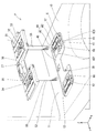
便座固定プレートPは、図1に示すように、便器本体10の後部上面11に固定される。以下、各構成部材において、便器本体10の便座に着座した状態の人から見て便器本体10の設置状態における上側(図1のZ軸正方向側)を上側、下側(図1のZ軸負方向側)を下側、便器本体10の便座に着座した状態の人から見て前側(図1のX軸正方向側)を前側、後側(図1のX軸負方向側)を後側、右側(図1のY軸正方向側)を右側、左側(図1のY軸負方向側)を左側として説明する。
<Embodiment>
As shown in FIG. 1, the toilet seat fixing plate P is fixed to the rear upper surface 11 of the toilet body 10. Hereinafter, in each component, the upper side (the Z-axis positive direction side in FIG. 1) in the installed state of the toilet body 10 when viewed from the person seated on the toilet seat of the toilet body 10 is the upper side and the lower side (Z-axis in FIG. 1). The negative side is the lower side, the front side (the X-axis positive side in FIG. 1) is the front side, and the rear side (the X-axis negative direction side in FIG. 1) is the rear when viewed from the person seated on the toilet seat of the toilet body 10. The side and the right side (the Y-axis positive direction side in FIG. 1) will be described as the right side, and the left side (the Y-axis negative direction side in FIG. 1) will be described as the left side.

便器本体10の後部上面11には、2つの取付穴12が設けられている。2つの取付穴12は、所定間隔を有して左右に並んでいる。 Two mounting holes 12 are provided on the rear upper surface 11 of the toilet bowl body 10. The two mounting holes 12 are arranged side by side with a predetermined interval.

便器本体10に固定された状態の便座固定プレートPには、図3に示すように、便座装置20が取り付けられる。便座装置20は、便座(図示せず)、便蓋21及び装置本体22を備えている。装置本体22は、便座及び便蓋21を回転自在に支持する。装置本体22は、局部洗浄ノズルなどを収納している。 As shown in FIG. 3, the toilet seat device 20 is attached to the toilet seat fixing plate P fixed to the toilet body 10. The toilet seat device 20 includes a toilet seat (not shown), a toilet lid 21, and a device body 22. The device body 22 rotatably supports the toilet seat and the toilet lid 21. The apparatus main body 22 houses a local cleaning nozzle and the like.

便座装置20は、便座固定プレートPの固定位置を前後方向に調整することによって、前後方向の寸法が異なる便器本体10に取り付けることができる。前後方向の寸法とは、左右の取付孔の中心を結んだ線から便器本体10の前端までの寸法である。 The toilet seat device 20 can be attached to the toilet body 10 having different dimensions in the front-rear direction by adjusting the fixing position of the toilet seat fixing plate P in the front-rear direction. The dimension in the front-rear direction is the dimension from the line connecting the centers of the left and right mounting holes to the front end of the toilet bowl body 10.

便座固定プレートPは、図1に示すように、上面プレート30、下面プレート40、ボルト50及びボルト取付部品60を備えている。下面プレート40はベースプレートに対応する。上面プレート30は下面プレート40に対して上昇及び下降する。便座固定プレートPは、便座装置20をリフトアップする機構を有している。 As shown in FIG. 1, the toilet seat fixing plate P includes an upper surface plate 30, a lower surface plate 40, a bolt 50, and a bolt mounting component 60. The bottom plate 40 corresponds to the base plate. The top plate 30 rises and falls with respect to the bottom plate 40. The toilet seat fixing plate P has a mechanism for lifting up the toilet seat device 20.

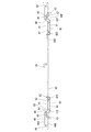
ボルト50は、図2に示すように、軸部材51、筒部材52、及びバネ部材53を有している。ボルト50は、固定ネジ31及び固定プレート32によって、上面プレート30に固定されている(図1参照)。 As shown in FIG. 2, the bolt 50 has a shaft member 51, a tubular member 52, and a spring member 53. The bolt 50 is fixed to the upper surface plate 30 by the fixing screw 31 and the fixing plate 32 (see FIG. 1).

軸部材51は、図2に示すように、筒部材52の内側に挿入されている。軸部材51は円柱状をなしている。軸部材51は、上軸部材51Aと下軸部材51Bとを連結したものである。軸部材51(上軸部材51A)の上端には、固定ネジ31がねじ込まれるネジ穴54が形成されている。 As shown in FIG. 2, the shaft member 51 is inserted inside the tubular member 52. The shaft member 51 has a columnar shape. The shaft member 51 is formed by connecting the upper shaft member 51A and the lower shaft member 51B. A screw hole 54 into which the fixing screw 31 is screwed is formed at the upper end of the shaft member 51 (upper shaft member 51A).

筒部材52は、胴部55及び頭部56を有している。胴部55は円筒状をなしている。胴部55の外周面にはネジ山が形成されている。胴部55の下端は、下端部材57によって塞がれている。頭部56は、後述するボルト取付部品60の凹部68に嵌合する略方形の平板状をなしている。 The tubular member 52 has a body portion 55 and a head portion 56. The body portion 55 has a cylindrical shape. A screw thread is formed on the outer peripheral surface of the body portion 55. The lower end of the body portion 55 is closed by the lower end member 57. The head 56 has a substantially square flat plate shape that fits into the recess 68 of the bolt mounting component 60 described later.

バネ部材53は、圧縮コイルバネである。バネ部材53は、胴部55の下端部材57と軸部材51の下端との間に収納されている。バネ部材53は、軸部材51に対し上向きの弾性力を付与する。 The spring member 53 is a compression coil spring. The spring member 53 is housed between the lower end member 57 of the body portion 55 and the lower end of the shaft member 51. The spring member 53 applies an upward elastic force to the shaft member 51.

上面プレート30には、図3に示すように、便座装置20を取り付け状態にロックするロック部33が設けられている。ロック部33は、前端が自由端の片持ち状をなしている。 As shown in FIG. 3, the upper surface plate 30 is provided with a lock portion 33 that locks the toilet seat device 20 in the attached state. The lock portion 33 has a cantilever shape at the front end having a free end.

上面プレート30には、固定ネジ31の軸部が挿入される挿入孔34が設けられている。挿入孔34は、左右に一対設けられている。挿入孔34は、前後方向に長く延びている。 The top plate 30 is provided with an insertion hole 34 into which the shaft portion of the fixing screw 31 is inserted. A pair of insertion holes 34 are provided on the left and right sides. The insertion hole 34 extends long in the front-rear direction.

挿入孔34の縁部には、図3に示すように、固定プレート32が載置される。固定プレート32は、略方形の板状をなしている。固定プレート32は、上面プレート30に設けられた位置決め部35によって前後方向の位置が決められる。位置決め部35は、前後方向に凹凸が並んだ歯状をなしている。各凹凸は、上側から見ると、三角形状をなしている。固定プレート32には、調整した任意の位置で位置決め部35に嵌合する突部が設けられている。 As shown in FIG. 3, a fixing plate 32 is placed on the edge of the insertion hole 34. The fixing plate 32 has a substantially square plate shape. The position of the fixed plate 32 in the front-rear direction is determined by the positioning portion 35 provided on the top plate 30. The positioning portion 35 has a tooth shape in which irregularities are arranged in the front-rear direction. Each unevenness has a triangular shape when viewed from above. The fixing plate 32 is provided with a protrusion that fits into the positioning portion 35 at an arbitrary adjusted position.

固定ネジ31は、図2に示すように、固定プレート32の貫通孔32H及び上面プレート30の挿入孔34を貫通してボルト50のネジ穴54にねじ込まれる。これによって、ボルト50は、上面プレート30から垂下した状態で固定される。 As shown in FIG. 2, the fixing screw 31 penetrates the through hole 32H of the fixing plate 32 and the insertion hole 34 of the upper surface plate 30 and is screwed into the screw hole 54 of the bolt 50. As a result, the bolt 50 is fixed in a state of hanging from the top plate 30.

上面プレート30には、下面プレート40の係止片38に係止する係止部材36が備えられている(図2参照)。係止部材36は、左右方向に移動自在である。係止部材36には、図示しない圧縮コイルバネによって、係止片38との係止状態を維持する方向に弾性力が付与されている。これによって、上面プレート30と下面プレート40とは組み付け状態に保持される。 The upper surface plate 30 is provided with a locking member 36 that engages with the locking piece 38 of the lower surface plate 40 (see FIG. 2). The locking member 36 is movable in the left-right direction. An elastic force is applied to the locking member 36 in a direction of maintaining a locked state with the locking piece 38 by a compression coil spring (not shown). As a result, the upper surface plate 30 and the lower surface plate 40 are held in the assembled state.

上面プレート30には、上面プレート30と下面プレート40とを分離する際に操作する突起部分37が設けられている(図1参照)。突起部分37を操作することによって、係止部材36は係止片38との係止が解除される方向に移動する。これによって、上面プレート30と下面プレート40とが分離される。 The upper surface plate 30 is provided with a protruding portion 37 that is operated when the upper surface plate 30 and the lower surface plate 40 are separated (see FIG. 1). By operating the protruding portion 37, the locking member 36 moves in the direction in which the locking member 36 is released from the locking piece 38. As a result, the upper surface plate 30 and the lower surface plate 40 are separated.

ボルト取付部品60は、図5に示すように、エラストマーなどからなる弾性体である。ボルト取付部品60は、下面プレート40に対して前後方向に移動する。 As shown in FIG. 5, the bolt mounting component 60 is an elastic body made of an elastomer or the like. The bolt mounting component 60 moves in the front-rear direction with respect to the bottom plate 40.

ボルト取付部品60は、上側から見ると、方形状をなす本体部61を有している。本体部61の外縁は、前後方向に延びる一対の第1縁部63と、左右方向に延びる一対の第2縁部64とを備えている。 The bolt mounting component 60 has a main body portion 61 that is rectangular when viewed from above. The outer edge of the main body 61 includes a pair of first edge portions 63 extending in the front-rear direction and a pair of second edge portions 64 extending in the left-right direction.

本体部61には、ボルト50の胴部55を上下方向に通す通し穴62が形成されている。これによって、ボルト取付部品60は、下面プレート40におけるボルト50の取り付け位置を示す。通し穴62は、上側から見ると前後方向に長い形状をなしている。 The main body 61 is formed with a through hole 62 through which the body 55 of the bolt 50 is passed in the vertical direction. Thereby, the bolt mounting component 60 indicates the mounting position of the bolt 50 on the bottom plate 40. The through hole 62 has a long shape in the front-rear direction when viewed from above.

本体部61には、後述する下面プレート40の位置決め部45に嵌合する嵌合部65が設けられている(図4参照)。嵌合部65は、第1縁部63に設けられている。嵌合部65は、1つの突部である。 The main body 61 is provided with a fitting portion 65 that fits into the positioning portion 45 of the lower surface plate 40, which will be described later (see FIG. 4). The fitting portion 65 is provided on the first edge portion 63. The fitting portion 65 is one protrusion.

本体部61には、図6に示すように、下面プレート40の上面に係止する係止部66が設けられている。係止部66は、本体部61から左方及び右方に突出している。係止部66は、第1縁部63の前端から後端まで続いている。 As shown in FIG. 6, the main body 61 is provided with a locking portion 66 that locks to the upper surface of the lower surface plate 40. The locking portion 66 projects to the left and right from the main body portion 61. The locking portion 66 continues from the front end to the rear end of the first edge portion 63.

左右の係止部66のうち第1係止部66は、下面プレート40の上面に沿う板状をなしている。第1係止部66Fは、図5に示すように、上側から見ると、前後方向に長い方形状をなしている。第1係止部66Fは、後述する離脱防止部46の下側に配置される。 Of the left and right locking portions 66, the first locking portion 66 has a plate shape along the upper surface of the lower surface plate 40. As shown in FIG. 5, the first locking portion 66F has a long rectangular shape in the front-rear direction when viewed from above. The first locking portion 66F is arranged below the detachment prevention portion 46, which will be described later.

第1係止部66Fには、図4に示すように、リブ67が設けられている。リブ67は、係止部66から下向きに突出している。リブ67は、前後方向に延びている。リブ67は、下面プレート40の溝部43に差し込まれる。これによって、ボルト取付部品60は、左右方向における中央側への移動が制限される。 As shown in FIG. 4, the first locking portion 66F is provided with a rib 67. The rib 67 projects downward from the locking portion 66. The rib 67 extends in the front-rear direction. The rib 67 is inserted into the groove 43 of the bottom plate 40. As a result, the bolt mounting component 60 is restricted from moving toward the center in the left-right direction.

左右の係止部66のうち第2係止部66Sは、下面プレート40の開口部41の周縁に係止する爪状をなしている。 Of the left and right locking portions 66, the second locking portion 66S has a claw shape that locks to the peripheral edge of the opening 41 of the lower surface plate 40.

本体部61の上面は、図6に示すように、第1係止部66F及び第2係止部66Sの上面よりも一段下がった位置に形成されている。これによって、本体部61の上面には、第1係止部66F及び第2係止部66Sによって区画された凹部68が形成されている。凹部68には、ボルト50の頭部56が嵌合する。 As shown in FIG. 6, the upper surface of the main body 61 is formed at a position one step lower than the upper surfaces of the first locking portion 66F and the second locking portion 66S. As a result, a recess 68 partitioned by the first locking portion 66F and the second locking portion 66S is formed on the upper surface of the main body portion 61. The head 56 of the bolt 50 is fitted in the recess 68.

下面プレート40は、一枚の金属板を加工して形成されている。下面プレート40の上面には、上面プレート30が係止する係止片38が設けられている。 The bottom plate 40 is formed by processing a single metal plate. A locking piece 38 for locking the upper surface plate 30 is provided on the upper surface of the lower surface plate 40.

下面プレート40には、図4に示すように、ボルト取付部品60が嵌合する開口部41が形成されている。開口部41は、左右に一対設けられている。左右の開口部41の中心線の間隔は、便器本体10の取付穴12の中心の間隔と同じ間隔で形成されている。 As shown in FIG. 4, the bottom plate 40 is formed with an opening 41 into which the bolt mounting component 60 is fitted. A pair of openings 41 are provided on the left and right sides. The distance between the center lines of the left and right openings 41 is the same as the distance between the centers of the mounting holes 12 of the toilet bowl body 10.

開口部41は、前後方向に長い方形状をなしている。開口部41の前後方向の寸法は、ボルト取付部品60の前後方向の寸法よりも大きい。これによって、ボルト取付部品60は、下面プレート40に対して、前後方向に位置を変えることができる。ボルト取付部品60の移動する範囲は、便座及び便蓋21の前端を便器本体10の前端よりわずかに前方へ突出するように調整できる範囲である。 The opening 41 has a long rectangular shape in the front-rear direction. The front-rear dimension of the opening 41 is larger than the front-rear dimension of the bolt mounting component 60. As a result, the bolt mounting component 60 can be repositioned in the front-rear direction with respect to the bottom plate 40. The moving range of the bolt mounting component 60 is a range in which the front ends of the toilet seat and the toilet lid 21 can be adjusted so as to project slightly forward from the front end of the toilet bowl body 10.

開口部41の周縁は、図5に示すように、前後方向に延びる一対の第1開口縁部42Fと、左右方向に延びる一対の第2開口縁部42Sとを有している。 As shown in FIG. 5, the peripheral edge of the opening 41 has a pair of first opening edge portions 42F extending in the front-rear direction and a pair of second opening edge portions 42S extending in the left-right direction.

一対の第1開口縁部42Fは、平行である。一対の第1開口縁部42Fは、直線状に延びている。一対の第1開口縁部42Fには、ボルト取付部品60の一対の第1縁部63が近接する。近接した結果、接触してもよい。これによって、ボルト取付部品60は左右方向の移動が制限される。 The pair of first opening edges 42F are parallel. The pair of first opening edge portions 42F extend linearly. A pair of first edge portions 63 of the bolt mounting component 60 is close to the pair of first opening edge portions 42F. As a result of close proximity, they may come into contact. As a result, the bolt mounting component 60 is restricted from moving in the left-right direction.

下面プレート40には、図4に示すように、前後方向に長い溝部43が形成されている。溝部43は、開口部41の左側および右側の何れかに並んで設けられている。溝部43の前後方向の寸法は、ボルト取付部品60の前後方向の寸法よりも大きい。溝部43には、ボルト取付部品60のリブ67が差し入れられる。 As shown in FIG. 4, the bottom plate 40 is formed with a groove 43 that is long in the front-rear direction. The groove 43 is provided side by side on either the left side or the right side of the opening 41. The front-rear dimension of the groove 43 is larger than the front-rear dimension of the bolt mounting component 60. The rib 67 of the bolt mounting component 60 is inserted into the groove 43.

下面プレート40には、図5に示すように、ボルト取付部品60の移動を許容しつつボルト取付部品60を調整した位置に保持する保持部44が備えられている。保持部44は、位置決め部45と離脱防止部46とを有している。位置決め部45は、ボルト取付部品60の前後方向の位置決めをする。離脱防止部46は、ボルト取付部品60の離脱を防止する。 As shown in FIG. 5, the bottom plate 40 is provided with a holding portion 44 that holds the bolt mounting component 60 at an adjusted position while allowing the bolt mounting component 60 to move. The holding portion 44 has a positioning portion 45 and a detachment prevention portion 46. The positioning unit 45 positions the bolt mounting component 60 in the front-rear direction. The detachment prevention unit 46 prevents the bolt mounting component 60 from detaching.

位置決め部45は、一対の第1開口縁部42Fのうちの一方に設けられている。位置決め部45は、前後方向に凹凸が並んだ歯状をなしている。各凹凸は、上側から見ると、三角形状をなしている。位置決め部45の任意の位置に、ボルト取付部品60の嵌合部65が嵌合する。これによって、ボルト取付部品60は前後方向の移動が制限される。 The positioning portion 45 is provided on one of the pair of first opening edge portions 42F. The positioning portion 45 has a tooth shape in which irregularities are arranged in the front-rear direction. Each unevenness has a triangular shape when viewed from above. The fitting portion 65 of the bolt mounting component 60 is fitted at an arbitrary position of the positioning portion 45. As a result, the bolt mounting component 60 is restricted from moving in the front-rear direction.

離脱防止部46は、エラストマーなどからなる弾性体である。離脱防止部46は、ボルト取付部品60の第1係止部66Fに被さるブリッジ形状をなしている。離脱防止部46は、図6に示すように、下面プレート40の上面に載置された第1係止部66Fの上側に被さることによってボルト取付部品60の離脱を防ぐ。離脱防止部46は、上側に弾性変形することによって、ボルト取付部品60の移動を許容する。 The detachment prevention portion 46 is an elastic body made of an elastomer or the like. The detachment prevention portion 46 has a bridge shape that covers the first locking portion 66F of the bolt mounting component 60. As shown in FIG. 6, the detachment prevention portion 46 prevents the bolt mounting component 60 from detaching by covering the upper side of the first locking portion 66F mounted on the upper surface of the lower surface plate 40. The detachment prevention portion 46 allows the bolt mounting component 60 to move by elastically deforming upward.

離脱防止部46は、図5に示すように、前後方向に長い。離脱防止部46の前後方向の寸法は、開口部41の前後方向の寸法と同等の寸法である。離脱防止部46には、前後方向の長さ寸法を示す目盛りが記されている。 As shown in FIG. 5, the detachment prevention portion 46 is long in the front-rear direction. The dimension of the detachment prevention portion 46 in the front-rear direction is the same as the dimension of the opening 41 in the front-rear direction. The detachment prevention portion 46 is marked with a scale indicating the length dimension in the front-rear direction.

離脱防止部46は、図4に示すように、本体部46Aと、固定部46Bとを備えている。固定部46Bは、離脱防止部46の前後方向における両端部に設けられている。固定部46Bには、ネジSが挿通される切欠部47が設けられている。前側の固定部46Bの切欠部47は、前側が開放されている。後側の固定部46Bの切欠部47は、後側が開放されている。ネジSは、切欠部47の周縁に上側から係止し、下面プレート40の貫通孔48にねじ込まれる。これによって、離脱防止部46は、下面プレート40に固定される。 As shown in FIG. 4, the detachment prevention portion 46 includes a main body portion 46A and a fixing portion 46B. The fixing portions 46B are provided at both ends of the detachment prevention portion 46 in the front-rear direction. The fixing portion 46B is provided with a notch portion 47 through which the screw S is inserted. The front side of the notch 47 of the fixed portion 46B on the front side is open. The notch 47 of the fixed portion 46B on the rear side is open on the rear side. The screw S is locked to the peripheral edge of the notch 47 from above and screwed into the through hole 48 of the lower surface plate 40. As a result, the detachment prevention portion 46 is fixed to the lower surface plate 40.

本体部46Aは、図6に示すように、固定部46Bよりも一段上側に位置する。本体部46Aは、下面プレート40の上面と平行に配置される。本体部46Aの外縁は、図5に示すように、前後方向に延びる一対の外縁部49を有している。一対の外縁部49は、直線状に延びている。一対の外縁部49のうちの一方は、上側から見ると、第1開口縁部42Fに沿っている。 As shown in FIG. 6, the main body portion 46A is located one step above the fixed portion 46B. The main body 46A is arranged parallel to the upper surface of the lower surface plate 40. As shown in FIG. 5, the outer edge of the main body 46A has a pair of outer edges 49 extending in the front-rear direction. The pair of outer edge portions 49 extend linearly. One of the pair of outer edge portions 49 is along the first opening edge portion 42F when viewed from above.

便座固定プレートPを用いて便器本体10に便座装置20を取り付ける作業の一例を説明する。既存の便座装置を便座装置20に取り替える場合は、既存の便座装置を便器本体10から取り外す。 An example of the work of attaching the toilet seat device 20 to the toilet body 10 using the toilet seat fixing plate P will be described. When replacing the existing toilet seat device with the toilet seat device 20, the existing toilet seat device is removed from the toilet bowl main body 10.

最初に、便座固定プレートPの便器本体10における取付位置を確認する。図示しないメジャーを用いて、便器本体10の取付穴12から便器本体10の前端までの長さ寸法を測り、便座固定プレートPの取付位置を決定する。 First, the mounting position of the toilet seat fixing plate P on the toilet body 10 is confirmed. Using a tape measure (not shown), the length dimension from the mounting hole 12 of the toilet bowl body 10 to the front end of the toilet bowl body 10 is measured, and the mounting position of the toilet seat fixing plate P is determined.

次に、便座固定プレートPにおいてボルト50の位置を調整する。まず、便座固定プレートPを便器本体10の後部上面11に仮置きし、上面プレート30の突起部分37を操作して、上面プレート30と下面プレート40とを分離する。 Next, the position of the bolt 50 is adjusted on the toilet seat fixing plate P. First, the toilet seat fixing plate P is temporarily placed on the rear upper surface 11 of the toilet body 10, and the protruding portion 37 of the upper surface plate 30 is operated to separate the upper surface plate 30 and the lower surface plate 40.

分離した上面プレート30から固定ネジ31、固定プレート32、及びボルト50を取り外す。この取り外し作業は左右のボルト50に対して行う。その後、上面プレート30に対しボルト50の取付位置を調整する。具体的には、上面プレート30の固定プレート32を設定位置に移動し、固定プレート32の突部を上面プレート30の位置決め部45に嵌合する。このとき、左右の固定プレート32の位置を揃える。その後、固定ネジ31によって、固定プレート32の下側にボルト50を固定する。 The fixing screw 31, the fixing plate 32, and the bolt 50 are removed from the separated top plate 30. This removal work is performed on the left and right bolts 50. After that, the mounting position of the bolt 50 is adjusted with respect to the top plate 30. Specifically, the fixing plate 32 of the upper surface plate 30 is moved to the set position, and the protrusion of the fixing plate 32 is fitted into the positioning portion 45 of the upper surface plate 30. At this time, the positions of the left and right fixing plates 32 are aligned. After that, the bolt 50 is fixed to the lower side of the fixing plate 32 by the fixing screw 31.

次に、下面プレート40に対しボルト取付部品60の取付位置を調整する。具体的には、まず、ボルト取付部品60を浮かせて、嵌合部65を位置決め部45から離脱させる。これによって、ボルト取付部品60を前後方向に移動できる。離脱防止部46は、上方に弾性変位し、ボルト取付部品60を抑えている。よって、離脱防止部46は、下面プレート40から離脱することが防止される。その後、ボルト取付部品60を所定の位置に配置し、嵌合部65を位置決め部45に嵌合させる。これによって、ボルト取付部品60は、調整した位置に保持される。 Next, the mounting position of the bolt mounting component 60 is adjusted with respect to the bottom plate 40. Specifically, first, the bolt mounting component 60 is floated to separate the fitting portion 65 from the positioning portion 45. As a result, the bolt mounting component 60 can be moved in the front-rear direction. The detachment prevention portion 46 is elastically displaced upward to suppress the bolt mounting component 60. Therefore, the detachment prevention portion 46 is prevented from detaching from the lower surface plate 40. After that, the bolt mounting component 60 is arranged at a predetermined position, and the fitting portion 65 is fitted to the positioning portion 45. As a result, the bolt mounting component 60 is held in the adjusted position.

次に、下面プレート40を便器本体10の後部上面11に仮置きする。具体的には、ボルト取付部品60が便器本体10の取付穴12の上側に位置するように下面プレート40を配置する。 Next, the lower surface plate 40 is temporarily placed on the rear upper surface 11 of the toilet bowl body 10. Specifically, the lower surface plate 40 is arranged so that the bolt mounting component 60 is located above the mounting hole 12 of the toilet body 10.

次に、上面プレート30を下面プレート40に組み付ける。上面プレート30のボルト50を、下面プレート40のボルト取付部品60に通して、上面プレート30を上から押す。係止部材36が係止片38に係止し、上面プレート30と下面プレート40とが組み付け状態になる。ボルト50の頭部56は、ボルト取付部品60の凹部68に嵌合する。 Next, the upper surface plate 30 is assembled to the lower surface plate 40. The bolt 50 of the upper surface plate 30 is passed through the bolt mounting component 60 of the lower surface plate 40, and the upper surface plate 30 is pushed from above. The locking member 36 is locked to the locking piece 38, and the upper surface plate 30 and the lower surface plate 40 are in an assembled state. The head 56 of the bolt 50 fits into the recess 68 of the bolt mounting component 60.

その後、便座固定プレートPを便器本体10に固定する。具体的には、図2に示すように、便器本体10の取付穴12を貫通したボルト50の先端部に、パッキン13及びナット14を取り付けて固定する。 After that, the toilet seat fixing plate P is fixed to the toilet body 10. Specifically, as shown in FIG. 2, the packing 13 and the nut 14 are attached and fixed to the tip of the bolt 50 penetrating the mounting hole 12 of the toilet bowl body 10.

次に、図3に示すように、便座固定プレートPに便座装置20を取り付ける。具体的には、便座固定プレートPの前側の便器本体10の上面に便座装置20を置き、便座装置20を後側にスライドさせる。この作業は、便座固定プレートPの中心と便座装置20の左右方向の中心とを位置あわせして行う。便座固定プレートPが見えなくなるまで便座装置20を押すことによって、ロック部33が便座装置20を固定状態にロックする。以上により、便器本体10に便座装置20を取り付ける作業が完了する。 Next, as shown in FIG. 3, the toilet seat device 20 is attached to the toilet seat fixing plate P. Specifically, the toilet seat device 20 is placed on the upper surface of the toilet body 10 on the front side of the toilet seat fixing plate P, and the toilet seat device 20 is slid to the rear side. This work is performed by aligning the center of the toilet seat fixing plate P with the center of the toilet seat device 20 in the left-right direction. By pushing the toilet seat device 20 until the toilet seat fixing plate P disappears, the lock portion 33 locks the toilet seat device 20 in the fixed state. As described above, the work of attaching the toilet seat device 20 to the toilet body 10 is completed.

上記のように構成された実施形態の作用および効果について説明する。便座固定プレートPは、下面プレート40と、ボルト取付部品60と、保持部44と、を備えている。下面プレート40は、ボルト50によって便器本体10に固定される。ボルト取付部品60は、下面プレート40に対して移動し、ボルト50の取り付け位置を示す。保持部44は、下面プレート40に設けられている。保持部44は、ボルト取付部品60の移動を許容しつつボルト取付部品60を調整した位置に保持する。 The actions and effects of the embodiments configured as described above will be described. The toilet seat fixing plate P includes a lower surface plate 40, a bolt mounting component 60, and a holding portion 44. The bottom plate 40 is fixed to the toilet body 10 by bolts 50. The bolt mounting component 60 moves with respect to the bottom plate 40 and indicates the mounting position of the bolt 50. The holding portion 44 is provided on the lower surface plate 40. The holding portion 44 holds the bolt mounting component 60 at the adjusted position while allowing the bolt mounting component 60 to move.

この構成によれば、下面プレート40に対してボルト取付部品60の位置を調整し、調整した位置にボルト取付部品60を保持させて下面プレート40を便器本体10の上面に載置し、便器本体10に固定できる。施工時にボルト取付部品が離脱し、紛失等することを防ぐことができるから、固定作業が容易である。 According to this configuration, the position of the bolt mounting component 60 is adjusted with respect to the lower surface plate 40, the bolt mounting component 60 is held at the adjusted position, and the lower surface plate 40 is placed on the upper surface of the toilet bowl main body 10. Can be fixed at 10. Since it is possible to prevent the bolt mounting parts from coming off and being lost during construction, the fixing work is easy.

保持部44は、弾性変形することによってボルト取付部品60の移動を許容する離脱防止部46を備えている。この構成によれば、離脱防止部46を弾性変形させてボルト取付部品60を移動できる。 The holding portion 44 includes a detachment prevention portion 46 that allows the bolt mounting component 60 to move by elastically deforming. According to this configuration, the detachment prevention portion 46 can be elastically deformed to move the bolt mounting component 60.

離脱防止部46は、ボルト取付部品60の一部に被さる形状である。この構成によれば、ボルト取付部品60の一部に被さることによってボルト取付部品60の離脱を防止できる。 The detachment prevention portion 46 has a shape that covers a part of the bolt mounting component 60. According to this configuration, it is possible to prevent the bolt mounting component 60 from coming off by covering a part of the bolt mounting component 60.

<他の実施形態>
本開示は上記記述及び図面によって説明した実施形態に限定されるものではなく、例えば次のような実施形態も本開示の技術的範囲に含まれる。
(1)上記実施形態では、ボルト取付部品60に通し穴62が形成されている。これに限らず、ボルト取付部品は、下面プレートにおけるボルトの位置を示すものであればよいから、通し穴が形成されていなくてもよい。
(2)上記実施形態では、便座固定プレートPは、便座装置20をリフトアップする機構を有している。これに限らず、便座固定プレートは、リフトアップ機構を有していなくてもよい。
(3)上記実施形態では、位置決め部45は前後方向に凹凸が並んだ歯状をなしている。これに限らず、位置決め部の形状は変更できる。
(4)上記実施形態では、離脱防止部46の構成を具体的に例示した。これに限らず、離脱防止部の構成は変更できる。
<Other Embodiments>
The present disclosure is not limited to the embodiments described by the above description and drawings, and for example, the following embodiments are also included in the technical scope of the present disclosure.
(1) In the above embodiment, a through hole 62 is formed in the bolt mounting component 60. Not limited to this, the bolt mounting component may not have a through hole because it may indicate the position of the bolt on the lower surface plate.
(2) In the above embodiment, the toilet seat fixing plate P has a mechanism for lifting up the toilet seat device 20. Not limited to this, the toilet seat fixing plate does not have to have a lift-up mechanism.
(3) In the above embodiment, the positioning portion 45 has a tooth shape in which irregularities are arranged in the front-rear direction. Not limited to this, the shape of the positioning portion can be changed.
(4) In the above embodiment, the configuration of the detachment prevention unit 46 is specifically illustrated. Not limited to this, the configuration of the detachment prevention unit can be changed.

P…便座固定プレート、10…便器本体、40…下面プレート(ベースプレート)、44…保持部、46…離脱防止部、50…ボルト、60…ボルト取付部品 P ... Toilet seat fixing plate, 10 ... Toilet bowl body, 40 ... Bottom plate (base plate), 44 ... Holding part, 46 ... Detachment prevention part, 50 ... Bolt, 60 ... Bolt mounting parts

Claims (5)

ボルトによって便器本体に固定されるベースプレートと、
前記ベースプレートに対して移動し、前記ボルトの取り付け位置を示すボルト取付部品と、
前記ベースプレートに設けられ、前記ボルト取付部品の移動を許容しつつ前記ボルト取付部品を調整した位置に保持する保持部と、
を備えている便座固定プレート。
The base plate, which is fixed to the toilet body with bolts,
Bolt mounting parts that move with respect to the base plate and indicate the mounting position of the bolt,
A holding portion provided on the base plate that holds the bolt mounting component in an adjusted position while allowing the bolt mounting component to move.
Toilet seat fixing plate equipped with.
前記保持部は、弾性変形することによって前記ボルト取付部品の移動を許容する離脱防止部を備えている請求項1に記載の便座固定プレート。 The toilet seat fixing plate according to claim 1, wherein the holding portion includes a detachment prevention portion that allows the bolt mounting component to move by elastically deforming. 前記離脱防止部は、前記ボルト取付部品の一部に被さる形状である請求項2に記載の便座固定プレート。 The toilet seat fixing plate according to claim 2, wherein the detachment prevention portion has a shape that covers a part of the bolt mounting parts. 前記保持部には、前記ボルト取付部品の移動方向の長さ寸法を示す目盛りが設けられている請求項1から請求項3までの何れか一項に記載の便座固定プレート。 The toilet seat fixing plate according to any one of claims 1 to 3, wherein the holding portion is provided with a scale indicating a length dimension in a moving direction of the bolt mounting component. 請求項1から請求項4までの何れか一項に記載の便座固定プレートを便器本体に固定する便座固定プレートの施工方法であって、
前記ベースプレートに対して前記ボルト取付部品の取付位置を調整し、前記保持部によって前記ボルト取付部品を調整した位置に保持し、前記ベースプレートを前記便器本体に固定する便座固定プレートの施工方法。
A method of constructing a toilet seat fixing plate for fixing the toilet seat fixing plate according to any one of claims 1 to 4 to the toilet bowl body.
A method of constructing a toilet seat fixing plate in which a mounting position of the bolt mounting component is adjusted with respect to the base plate, the bolt mounting component is held at the adjusted position by the holding portion, and the base plate is fixed to the toilet bowl body.
JP2019226198A 2019-12-16 2019-12-16 Toilet seat fixing plate and installation method of toilet seat fixing plate Active JP7411403B2 (en)

Priority Applications (1)

Application Number Priority Date Filing Date Title
JP2019226198A JP7411403B2 (en) 2019-12-16 2019-12-16 Toilet seat fixing plate and installation method of toilet seat fixing plate

Applications Claiming Priority (1)

Application Number Priority Date Filing Date Title
JP2019226198A JP7411403B2 (en) 2019-12-16 2019-12-16 Toilet seat fixing plate and installation method of toilet seat fixing plate

Publications (2)

Publication Number Publication Date
JP2021094130A true JP2021094130A (en) 2021-06-24
JP7411403B2 JP7411403B2 (en) 2024-01-11

Family

ID=76429951

Family Applications (1)

Application Number Title Priority Date Filing Date
JP2019226198A Active JP7411403B2 (en) 2019-12-16 2019-12-16 Toilet seat fixing plate and installation method of toilet seat fixing plate

Country Status (1)

Country Link
JP (1) JP7411403B2 (en)

Family Cites Families (3)

* Cited by examiner, † Cited by third party
Publication number Priority date Publication date Assignee Title
JP2007275348A (en) 2006-04-07 2007-10-25 Microjenics Inc Toilet seat-mounting structure
JP6737064B2 (en) 2016-08-17 2020-08-05 Toto株式会社 Sanitary washing equipment
JP6847387B2 (en) 2016-11-28 2021-03-24 株式会社Lixil Toilet seat device

Also Published As

Publication number Publication date
JP7411403B2 (en) 2024-01-11

Similar Documents

Publication Publication Date Title
KR100794440B1 (en) Magnetic tape measure, end hook and method of assembling tape measure end hook
JP2013173613A (en) Device box for elevator
KR101932220B1 (en) Universal setting jig apparatus for block type
JP2021094130A (en) Toilet seat fixation plate, and construction method of toilet seat fixation plate
US9188274B2 (en) Releasable support mounts and related methods
JP5470584B2 (en) Gaming machine housing structure
JP5226262B2 (en) Magnetic wearing member to be attached to the tape measure side of the magnet holder
JPH0838720A (en) Hinge structure for front frame and outer frame of pachinko machine
JP4788733B2 (en) Image display device
JP2544460Y2 (en) Seat floor mounting bracket
JP5602036B2 (en) Mounting jig for screw fixing member
JP2014095632A (en) Level
JP6760057B2 (en) electronic balance
JP2525906B2 (en) Lock receiver
JP4580864B2 (en) Grating fixture and grating
JP2009192305A (en) Grommet testing jig
JPH075660Y2 (en) Printed circuit board support device
US8511027B2 (en) Device for mounting and locking a casing to a suspension
JP3224508U (en) Laser test light source fixing device
JPS5910575Y2 (en) panel equipment
KR101569701B1 (en) Camera and grip unit
JP2570700Y2 (en) Toilet seat box installation structure
CN116293223A (en) Quick release device
JPH11225836A (en) Mounting gage of locking device for use in earthquake, mounting method for the device, and manufacture of furniture having the device
JP4741250B2 (en) Moving member stop device

Legal Events

Date Code Title Description
A711 Notification of change in applicant

Free format text: JAPANESE INTERMEDIATE CODE: A712

Effective date: 20210127

A621 Written request for application examination

Free format text: JAPANESE INTERMEDIATE CODE: A621

Effective date: 20221018

A977 Report on retrieval

Free format text: JAPANESE INTERMEDIATE CODE: A971007

Effective date: 20230713

A131 Notification of reasons for refusal

Free format text: JAPANESE INTERMEDIATE CODE: A131

Effective date: 20230801

A521 Request for written amendment filed

Free format text: JAPANESE INTERMEDIATE CODE: A523

Effective date: 20230925

TRDD Decision of grant or rejection written
A01 Written decision to grant a patent or to grant a registration (utility model)

Free format text: JAPANESE INTERMEDIATE CODE: A01

Effective date: 20231128

A61 First payment of annual fees (during grant procedure)

Free format text: JAPANESE INTERMEDIATE CODE: A61

Effective date: 20231225

R150 Certificate of patent or registration of utility model

Ref document number: 7411403

Country of ref document: JP

Free format text: JAPANESE INTERMEDIATE CODE: R150