JP2021089351A - Head-mounted system and information processing apparatus - Google Patents
Head-mounted system and information processing apparatus Download PDFInfo
- Publication number
- JP2021089351A JP2021089351A JP2019219074A JP2019219074A JP2021089351A JP 2021089351 A JP2021089351 A JP 2021089351A JP 2019219074 A JP2019219074 A JP 2019219074A JP 2019219074 A JP2019219074 A JP 2019219074A JP 2021089351 A JP2021089351 A JP 2021089351A
- Authority
- JP
- Japan
- Prior art keywords
- eye
- image
- head
- display device
- mounted system
- Prior art date
- Legal status (The legal status is an assumption and is not a legal conclusion. Google has not performed a legal analysis and makes no representation as to the accuracy of the status listed.)
- Pending
Links
- 230000010365 information processing Effects 0.000 title claims description 7
- 210000001508 eye Anatomy 0.000 claims abstract description 129
- 238000003384 imaging method Methods 0.000 claims description 45
- 208000006992 Color Vision Defects Diseases 0.000 claims description 16
- 230000002093 peripheral effect Effects 0.000 claims description 15
- 208000004350 Strabismus Diseases 0.000 claims description 14
- 208000036693 Color-vision disease Diseases 0.000 claims description 13
- 210000003128 head Anatomy 0.000 claims description 8
- 208000001140 Night Blindness Diseases 0.000 claims description 7
- 238000012545 processing Methods 0.000 claims description 5
- 201000009310 astigmatism Diseases 0.000 claims description 3
- 201000007254 color blindness Diseases 0.000 claims description 3
- 230000004304 visual acuity Effects 0.000 claims description 3
- 230000004044 response Effects 0.000 claims description 2
- 238000000034 method Methods 0.000 abstract description 16
- 230000006870 function Effects 0.000 description 7
- 238000010586 diagram Methods 0.000 description 6
- 101100507312 Invertebrate iridescent virus 6 EF1 gene Proteins 0.000 description 5
- 230000008859 change Effects 0.000 description 4
- 238000012790 confirmation Methods 0.000 description 4
- 238000013528 artificial neural network Methods 0.000 description 2
- 238000004891 communication Methods 0.000 description 2
- 238000012986 modification Methods 0.000 description 2
- 230000004048 modification Effects 0.000 description 2
- 230000008569 process Effects 0.000 description 2
- 125000002066 L-histidyl group Chemical group [H]N1C([H])=NC(C([H])([H])[C@](C(=O)[*])([H])N([H])[H])=C1[H] 0.000 description 1
- 208000003464 asthenopia Diseases 0.000 description 1
- 210000005252 bulbus oculi Anatomy 0.000 description 1
- 210000005069 ears Anatomy 0.000 description 1
- 230000000694 effects Effects 0.000 description 1
- 210000000744 eyelid Anatomy 0.000 description 1
- 239000011521 glass Substances 0.000 description 1
- 238000010801 machine learning Methods 0.000 description 1
- 239000004984 smart glass Substances 0.000 description 1
Images


Classifications
-
- G—PHYSICS
- G02—OPTICS
- G02B—OPTICAL ELEMENTS, SYSTEMS OR APPARATUS
- G02B27/00—Optical systems or apparatus not provided for by any of the groups G02B1/00 - G02B26/00, G02B30/00
- G02B27/0093—Optical systems or apparatus not provided for by any of the groups G02B1/00 - G02B26/00, G02B30/00 with means for monitoring data relating to the user, e.g. head-tracking, eye-tracking
-
- G—PHYSICS
- G02—OPTICS
- G02B—OPTICAL ELEMENTS, SYSTEMS OR APPARATUS
- G02B27/00—Optical systems or apparatus not provided for by any of the groups G02B1/00 - G02B26/00, G02B30/00
- G02B27/01—Head-up displays
- G02B27/017—Head mounted
- G02B27/0172—Head mounted characterised by optical features
-
- G—PHYSICS
- G02—OPTICS
- G02B—OPTICAL ELEMENTS, SYSTEMS OR APPARATUS
- G02B27/00—Optical systems or apparatus not provided for by any of the groups G02B1/00 - G02B26/00, G02B30/00
- G02B27/01—Head-up displays
- G02B27/0101—Head-up displays characterised by optical features
- G02B2027/0138—Head-up displays characterised by optical features comprising image capture systems, e.g. camera
-
- G—PHYSICS
- G02—OPTICS
- G02B—OPTICAL ELEMENTS, SYSTEMS OR APPARATUS
- G02B27/00—Optical systems or apparatus not provided for by any of the groups G02B1/00 - G02B26/00, G02B30/00
- G02B27/01—Head-up displays
- G02B27/0101—Head-up displays characterised by optical features
- G02B2027/014—Head-up displays characterised by optical features comprising information/image processing systems
-
- G—PHYSICS
- G02—OPTICS
- G02B—OPTICAL ELEMENTS, SYSTEMS OR APPARATUS
- G02B27/00—Optical systems or apparatus not provided for by any of the groups G02B1/00 - G02B26/00, G02B30/00
- G02B27/01—Head-up displays
- G02B27/017—Head mounted
- G02B2027/0178—Eyeglass type
Abstract
Description
本発明は、頭部装着システム及び情報処理装置に関する。 The present invention relates to a head-mounted system and an information processing device.
ヘッドマウントディスプレイやスマートグラスと呼ばれる表示装置を備えたウェアラブルデバイスが知られている。特許文献1に示すように、このようなウェアラブルデバイスの1つの方式では、装着者の周囲の画像が撮像装置によって取り込まれ、その画像が表示装置に表示される。この方式によれば、利用者は、表示装置を通しながらも、周囲をあたかも直接見ているような感覚を得られる。さらに、高感度撮影が可能な撮像装置によって取得された画像を表示装置に表示すれば、真夜中でも日中と同様に活動することが可能となる。
Wearable devices equipped with display devices called head-mounted displays and smart glasses are known. As shown in
特許文献1に記載されたウェアラブルデバイスでは、撮影装置によって取得された画像がそのまま表示装置に表示される。そのため、何れの装着者に対しても同じ設定で画像が表示される。しかし、眼の状況は装着者ごとに異なるし、また、同一の装着者であっても時間の経過とともに眼の状況が変化しうる。本発明の1つの側面は、装着者の眼の状況に応じた周囲の表示を可能にするための技術を提供することを目的とする。
In the wearable device described in
上記課題に鑑みて、頭部装着システムであって、前記頭部装着システムの装着者の眼を撮影する眼撮影装置と、前記装着者の周囲を撮影する周囲撮影装置と、前記周囲撮影装置によって撮影された前記周囲の画像を前記装着者に向けて表示する表示装置と、前記眼撮影装置によって撮影された前記眼の画像に基づいて、前記表示装置における前記周囲の表示を調整する制御装置と、を備える頭部装着システムが提供される。 In view of the above problems, the head-mounted system includes an eye photographing device that photographs the eyes of the wearer of the head-mounted system, a peripheral photographing device that photographs the surroundings of the wearer, and the peripheral photographing device. A display device that displays the captured surrounding image toward the wearer, and a control device that adjusts the surrounding display on the display device based on the image of the eye taken by the eye imaging device. A head-mounted system comprising, is provided.
上記手段により、装着者の眼の状況に応じた周囲の表示が可能となる。 By the above means, it is possible to display the surroundings according to the condition of the wearer's eyes.
以下、添付図面を参照して実施形態を詳しく説明する。なお、以下の実施形態は特許請求の範囲に係る発明を限定するものでない。実施形態には複数の特徴が記載されているが、これらの複数の特徴の全てが発明に必須のものとは限らず、また、複数の特徴は任意に組み合わせられてもよい。さらに、添付図面においては、同一若しくは同様の構成に同一の参照番号を付し、重複した説明は省略する。 Hereinafter, embodiments will be described in detail with reference to the accompanying drawings. The following embodiments do not limit the invention according to the claims. Although a plurality of features are described in the embodiment, not all of the plurality of features are essential to the invention, and the plurality of features may be arbitrarily combined. Further, in the attached drawings, the same or similar configurations are designated by the same reference numbers, and duplicate explanations are omitted.
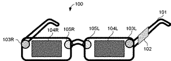
図1を参照して、一部の実施形態に係る頭部装着システム100の構成例について説明する。頭部装着システム100は、人間の頭部に装着された状態で使用されるシステムである。図1の頭部装着システム100は、眼鏡のような形状を有する。すなわち、フレーム101が装着者の耳及び鼻にかけられることによって、頭部装着システム100が装着者の頭部に支持される。これにかえて、頭部装着システム100は、ゴーグルやヘルメットのような形状を有してもよい。
A configuration example of the head-mounted
頭部装着システム100は、制御装置102と、周囲撮影装置103R、103Lと、表示装置104R、104Lと、眼撮影装置105R、105Lとを有する。周囲撮影装置103R、103Lを周囲撮影装置103と総称する。以下の周囲撮影装置103に関する説明は、周囲撮影装置103Rと周囲撮影装置103Lとの両方に当てはまる。同様に、表示装置104R、104Lを表示装置104と総称し、眼撮影装置105R、105Lを眼撮影装置105と総称する。制御装置102と、周囲撮影装置103と、表示装置104と、眼撮影装置105とはいずれもフレーム101に取り付けられている。
The head-mounted
制御装置102は、頭部装着システム100全体の動作を制御する。具体的な制御内容については後述する。制御装置102は、頭部装着システム100の各コンポーネントに電力を供給するバッテリと、頭部装着システム100以外の装置と通信するための通信装置を含んでいてもよい。
The
周囲撮影装置103は、装着者の周囲を撮影する。周囲とは、装着者の周りの全てではなく、一部であってもよい。周囲撮影装置103は、典型的に、装着者の前方を撮影可能な位置に取り付けられる。周囲撮影装置103の用途に応じて、周囲撮影装置103は、装着者の側方、上方又は後方を撮影可能な位置に取り付けられてもよい。周囲撮影装置103Lは、フレーム101の左側レンズ位置に取り付けられており、装着者の左目側から見た周囲を撮影する。周囲撮影装置103Rは、フレーム101の右側レンズ位置に取り付けられており、装着者の右目側から見た周囲を撮影する。レンズ位置とは、通常の眼鏡においてレンズが取り付けられる位置のことである。後述するように、装着者の周囲の画像が表示装置104に表示されるため、装着者が周囲を直接視認できなくてもよい。そのため、頭部装着システム100は、レンズを有していなくてもよいし、レンズ位置に不透明な支持板を有していてもよい。
The
表示装置104は、装着者に向けて画像を表示する。表示される画像は静止画像であってもよいし、動画像であってもよい。表示装置104は、装着者が視認可能な位置に取り付けされる。表示装置104Lは、フレーム101の左側レンズ位置に取り付けられており、装着者の左目に向けて画像を表示する。表示装置104Rは、フレーム101の右側レンズ位置に取り付けられており、装着者の右目に向けて画像を表示する。
The
眼撮影装置105は、装着者の眼を撮影する。撮影対象の眼は、眼球とまぶたとを含んでもよい。眼撮影装置105は、装着者の眼を撮影可能な位置に取り付けられる。眼撮影装置105Lは、フレーム101の左側レンズ位置に取り付けられており、装着者の左目を撮影する。眼撮影装置105Rは、フレーム101の右側レンズ位置に取り付けられており、装着者の右目を撮影する。
The
図2を参照して、頭部装着システム100の動作の概要について説明する。制御装置102は、プロセッサ121とメモリ122とを有する。制御装置102の動作は、メモリ122に記憶されたプログラムをプロセッサ121が実行することによって行われてもよい。これにかえて、制御装置102の動作の一部又は全部は、ASIC(特定用途向け集積回路)やFPGA(フィールドプログラマブルゲートアレイ)のような専用の処理回路によって実行されてもよい。制御装置102は、周囲撮影装置103、表示装置104及び眼撮影装置105の動作を制御する。
An outline of the operation of the head-mounted
周囲撮影装置103は、装着者の周囲を撮影することによって得られた周囲の画像(以下、周囲画像と呼ぶ)を制御装置102へ供給する。制御装置102は、この周囲画像を表示装置104に供給する。表示装置104は、この周囲画像を装着者に向けて表示する。また、眼撮影装置105は、装着者の眼を撮影することによって得られた眼の画像を制御装置102へ供給する。制御装置102は、眼の画像に基づいて、表示装置104における周囲の表示を調整する。制御装置102は、周囲撮影装置103の撮影パラメータと、周囲画像に対する処理と、表示装置104の表示パラメータとのうちの少なくとも1つを変更することによって、表示装置104における周囲の表示を調整してもよい。例えば、周囲撮影装置103のズーム、絞り、焦点距離などを変更することによって周囲の表示が調整されてもよい。また、周囲画像に対して色調変更や拡大縮小を行うことによって周囲の表示が調整されてもよい。さらに、表示装置104における輝度や明度、色彩、表示の中心位置を変更することによって周囲の表示が調整されてもよい。調整方法の具体例については後述する。
The
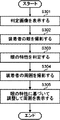
図3を参照して、頭部装着システム100の動作の詳細について説明する。一部の実施形態において、頭部装着システム100は、判定モードと使用モードとで動作可能である。判定モードとは、眼撮影装置105が装着者の眼を撮影し、制御装置102がこの眼の画像に基づいて眼の特性を判定するための動作モードのことである。使用モードとは、周囲撮影装置103が周囲を撮影し、制御装置102が眼の特性に基づいて表示を調整しつつ表示装置104が周囲画像を表示する動作モードのことである。図3の動作において、ステップS301〜S303が判定モードの処理であり、ステップS304〜S305が判定モードの処理である。
The details of the operation of the head-mounted
ステップS301で、制御装置102は、表示装置104に判定画像を表示する。判定画像とは、装着者の眼の特性を判定するために使用される画像のことである。眼の特性は、例えば、斜視と、色覚異常と、夜盲症と、視力と、乱視とのうちの少なくとも1つを含んでもよい。判定画像は、メモリ122に事前に記憶されていてもよいし、外部サーバ130から取得されてもよい。
In step S301, the
ステップS302で、制御装置102は、眼撮影装置105を使用して、判定画像を見ている装着者の眼の画像を取得する。ステップS303で、制御装置102は、眼の画像に基づいて、眼の特性を判定する。
In step S302, the
ステップS304で、制御装置102は、周囲撮影装置103を使用して、装着者の周囲の画像を取得する。ステップS305で、制御装置102は、眼の特性に基づいて調整して表示装置104に周囲画像を表示する。制御装置102は、ステップS304及びS305を繰り返し行うことによって、表示装置104に動画像を表示可能である。
In step S304, the
上述の方法は、頭部装着システム100単独で実行されてもよいし、頭部装着システム100と外部サーバ130とが連携して実行されてもよい。頭部装着システム100(具体的に、その制御装置102)と外部サーバ130とは互いに通信(特に無線通信)可能である。外部サーバ130は、プロセッサ131及びメモリ132を有するコンピュータ(情報処理装置)である。外部サーバ130の動作は、メモリ132に記憶されたプログラムをプロセッサ131が実行することによって行われてもよい。これにかえて、外部サーバ130の動作の一部又は全部は、ASICやFPGAのような専用の処理回路によって実行されてもよい。上述の方法が連携して行われる場合に、例えば、ステップS303で、制御装置102は、判定画像及び眼の画像を外部サーバ130に送信し、外部サーバ130は、判定画像及び眼の画像に基づいて眼の特性を判定し、判定結果を制御装置102に送信する。ステップS305で、制御装置102は、受信した眼の特性(すなわち、外部サーバ130からの応答)に基づいて、表示装置104における周囲の表示を調整する。使用される判定画像が制御装置102と外部サーバ130との間で事前に共有されている場合に、制御装置102は、ステップS303で判定画像を送信しなくてもよい。
The above-mentioned method may be executed by the head-mounted
図4〜図5を参照して、頭部装着システム100の動作の具体例について説明する。図4の具体例において、制御装置102は、眼撮影装置105によって撮影された眼の画像に基づいて眼が斜視を有するかどうかを判定し、眼が斜視を有すると判定された場合に、表示装置104に表示される周囲画像の位置を調整する。
A specific example of the operation of the head-mounted
具体的に、図4(a)に示すように、制御装置102は、表示装置104Lの中央にマーク403Lを表示し、表示装置104Rの中央にマーク403Rを表示する。また、制御装置102は、装着者400に対してマーク403L、403Rを見るように指示する。この指示は、表示装置104に文章を表示することによって行われてもよいし、音声によって行われてもよい。この結果、装着者400の左目401Lの視線402Lはマーク503Lに向かい、装着者400の右目401Rの視線402Rはマーク503Rに向かう。
Specifically, as shown in FIG. 4A, the
続いて、図4(b)に示すように、制御装置102は、表示装置104Lを非表示にする。装着者400が斜視を有する場合に、左目401Lの視線402Lがずれる。そのため、制御装置102は、視線402Lの変化に基づいて、斜視の方向及び角度を判定する。この角度が閾値を超える場合に、制御装置102は、装着者が斜視を有すると判定する。制御装置102は、右目401Rについても同様にして斜視の有無を判定される。以上の動作が図3の判定モード(すなわち、ステップS301〜S303)に対応する。
Subsequently, as shown in FIG. 4B, the
判定の結果、左目401Lが斜視を有し、右目401Rが斜視を有しないと判定されたとする。この場合に、制御装置102は、表示装置104Rにおいて周囲画像404Rの中心が中央に表示され、表示装置104Lにおいて周囲画像404Lの中心が左にずれて表示されるように周囲画像404R、404Lの表示を調整する。この調整は、周囲撮影装置103Lのレンズの方向を変更することによって行われてもよいし、画像処理によって周囲画像404Lの中心をずらすことによって行われてもよいし、表示装置104Lが画像の表示位置をずらすことによって行われてもよい。このように調整することによって、斜視を有する装着者400は自身にとって自然な視線で周囲画像404Lを見ることができるため、眼精疲労が軽減する。
As a result of the determination, it is determined that the
図5の具体例において、制御装置102は、眼撮影装置105によって撮影された眼の画像に基づいて眼が色覚異常を有するかどうかを判定し、眼が色覚異常を有すると判定された場合に、表示装置104に表示される周囲画像の色が装着者400に認識できるようにする。
In the specific example of FIG. 5, the
図5(a)に示す具体例で、制御装置102は、表示装置104Lの中央にマーク503Lを表示する。マーク503Lは、装着者400が色覚異常を有する場合に認識できない色で表示される。また、制御装置102は、表示装置104Lの一部(図5(a)の例では左上)に確認領域504Lを表示する。そして、制御装置102は、装着者400に対してマーク503Lが見えた場合に確認領域504Lを見るように指示する。この指示は、表示装置104にメッセージを表示することによって行われてもよいし、音声によって行われてもよい。装着者400の左目401Lの視線402Lがマーク503Lから確認領域504Lに移動した場合に、制御装置102は、装着者400が色覚異常を有しないと判定する。一方、このような視線402Lの移動を確認できない場合に、制御装置102は、装着者400が色覚異常を有すると判定する。右目401Rについても表示装置104Rにマーク503R及び確認領域504Rを表示することによって同様に判定される。
In the specific example shown in FIG. 5A, the
図5(b)に示す具体例で、制御装置102は、表示装置104Lを移動するマーク505Lを表示する。マーク505Lは、装着者400が色覚異常を有する場合に認識できない色で表示される。そして、制御装置102は、装着者400に対してマーク503Lを見続けるように指示する。この指示は、表示装置104にメッセージを表示することによって行われてもよいし、音声によって行われてもよい。装着者400の左目401Lの視線402Lがマーク505Lの移動に追従して移動した場合に、制御装置102は、装着者400が色覚異常を有しないと判定する。一方、このような視線402Lの移動を確認できない場合に、制御装置102は、装着者400が色覚異常を有すると判定する。右目401Rについても表示装置104Rにマーク505Rを表示することによって同様に判定される。
In the specific example shown in FIG. 5B, the
装着者400が色覚異常を有すると判定された場合に、制御装置102は、表示装置104に表示される周囲画像の色が装着者400に認識できるようにする。例えば、制御装置102は、装着者400が認識できない色を別の色に変更してもよい。これにかえて、制御装置102は、装着者400が認識できない色の領域に、その色の種類を示す文字を重畳してもよい。
When it is determined that the
続いて、別の特性の判定について説明する。制御装置102は、眼撮影装置105によって撮影された眼の画像に基づいて眼が夜盲症を有するかどうかを判定し、眼が夜盲症を有すると判定された場合に、表示装置104に表示される周囲画像の明度又は輝度を調整してもよい。装着者の眼が夜盲症を有するかどうかの判定は、図5(a)又は図5(b)の判定方法で、マーク503L又はマーク505Lを低い輝度で表示することによって行える。また、装着者の眼の視力や乱視を有するかどうかも、マーク503L又はマーク505Lをその判定に応じたものに変更することによって、同様に判定できる。
Subsequently, the determination of another characteristic will be described. The
図6を参照して、眼の特性を判定するための別の方法について説明する。この方法は、制御装置102によって実行されてもよいし、外部サーバ130によって実行されてもよい。以下では、外部サーバ130が実行する場合について説明する。
Another method for determining eye characteristics will be described with reference to FIG. This method may be executed by the
ステップS601で、外部サーバ130は、複数の人物について、個別の人物の眼の特性と、個別の人物の周囲を撮影した画像と、個別の人物の眼を撮影した画像とを含む集合を取得する。以下、このようなデータの収集対象の人物をサンプル提供者と呼ぶ。サンプル提供者は、頭部装着システム100を使用してデータを収集してもよい。具体的に、サンプル提供者は、自身の眼の特性(斜視の方向及び角度、色覚異常の有無など)を制御装置102に登録しておく。頭部装着システム100は、サンプル提供者の特性とともに、周囲撮影装置103によって撮影されたサンプル提供者の周囲の画像と、眼撮影装置105によって撮影されたサンプル提供者の眼の画像とを外部サーバ130へ送信する。外部サーバ130は、様々な特性を有するサンプル提供者からこのようなデータを収集する。具体的に、外部サーバ130は、所定の特性(例えば、色覚異常)を有する人物と、この特性を有しない人物との両方からデータを収集する。
In step S601, the
ステップS601でデータを取得するために、表示装置104が使用されないため、サンプル提供者は、制御装置102、周囲撮影装置103及び眼撮影装置105を有するが、表示装置104を有しない頭部装着システムを使用してデータを取得してもよい。この場合に、サンプル提供者が周囲を直接見ている間に撮影された眼の画像が、この周囲の画像とともに外部サーバ130へ提供される。一方、サンプル提供者が頭部装着システム100を使用する場合に、サンプル提供者が表示装置104に表示された周囲の画像を見ている間に撮影された眼の画像が、この周囲の画像とともに外部サーバ130へ提供される。
Since the
ステップS602で、外部サーバ130は、収集した複数の集合に基づいて、判定対象の人物の周囲を撮影した画像と、当該人物の眼を撮影した画像とを含む集合を入力として当該人物が所定の特性を有するかどうかを判定するための関数を決定する。以下ではこのような関数を特性判定関数と呼ぶ。特性判定関数の決定は、例えば機械学習によって行われる。例えば、収集したデータの周囲画像及び眼の画像を入力データとし、各特性(斜視や色覚異常)の有無を出力データとする関数をニューラルネットワークによって表現する。外部サーバ130は、サンプル提供者から提供された特性の有無を正解データとしてこのニューラルネットワークのパラメータを決定する。
In step S602, the
図7を参照して、特性判定関数を利用して表示装置104における表示を調整する方法について説明する。ステップS701で、判定対象者が装着した頭部装着システム100の制御装置102は、周囲撮影装置103によって撮影された周囲画像を取得し、周囲画像を表示装置104に表示する。さらに、制御装置102は、表示装置104が周囲画像を表示中に眼撮影装置105によって撮影された眼の画像を取得する。
A method of adjusting the display on the
ステップS702で、制御装置102は、ステップS701で取得された周囲画像及び眼の画像を外部サーバ130へ送信し、外部サーバ130はこれを受信する。
In step S702, the
ステップS703で、外部サーバ130は、周囲画像及び眼の画像を特性判定関数に入力することによって、判定対象者の眼の特性を判定する。ステップS704で、外部サーバ130は、眼の特性に基づいて、表示装置104における表示の調整方法を決定する。
In step S703, the
ステップS705で、外部サーバ130は、表示方法を制御装置102へ送信し、制御装置102はこれを受信する。ステップS706で、制御装置102は、周囲撮影装置103によって撮影された周囲の画像を取得する。ステップS707で、制御装置102は、受信した調整方法に従って、表示装置104における周囲の表示を調整する。
In step S705, the
制御装置102は、ステップS706及びS707を繰り返し行うことによって、表示装置104に動画像を表示可能である。また、制御装置102は、ステップS701〜S705の動作を定期的(例えば、月に1回)に行うことによって、判定対象者の眼の特性の経年変化に対応できる。ステップS704は、外部サーバ130で行われる代わりに、制御装置102によって行われてもよい。ステップS703も同様に、外部サーバ130で行われる代わりに、制御装置102によって行われてもよい。
The
図7の方法によれば、図4〜図5に示すような判定画像を表示することなく、通常の使用状態で(すなわち、周囲画像を表示装置104に表示しながら)装着者の眼の特性を判定できる。 According to the method of FIG. 7, the characteristics of the wearer's eyes under normal use conditions (that is, while displaying the surrounding image on the display device 104) without displaying the determination image as shown in FIGS. 4 to 5. Can be determined.
眼撮影装置105と、周囲撮影装置103と、表示装置104とのうちの少なくとも1つは、頭部装着システム100に脱着可能であってもよい。例えば、眼撮影装置105は、装着者の眼の特性を判定した後に、次回の判定まで使用されない。そのため、消費電力を低減するために、眼撮影装置105の電源がオフにされてもよいし、眼撮影装置105自体が取り外されてもよい。また、図6で説明したサンプルデータの収集において、表示装置104が使用されないため、表示装置104が取り外されてもよい。さらに、図3の判定モード(ステップS301〜S303)において周囲撮影装置103が使用されないため、消費電力を低減するために、周囲撮影装置103の電源がオフにされてもよいし、周囲撮影装置103自体が取り外されてもよい。
At least one of the
発明は上記実施形態に制限されるものではなく、発明の精神及び範囲から離脱することなく、様々な変更及び変形が可能である。従って、発明の範囲を公にするために請求項を添付する。 The invention is not limited to the above embodiments, and various modifications and modifications can be made without departing from the spirit and scope of the invention. Therefore, a claim is attached to make the scope of the invention public.
100 頭部装着システム、102 制御装置、103周囲撮影装置、104 表示装置、105 眼撮影装置 100 head-mounted system, 102 control device, 103 ambient imaging device, 104 display device, 105 eye imaging device
Claims (13)
前記頭部装着システムの装着者の眼を撮影する眼撮影装置と、
前記装着者の周囲を撮影する周囲撮影装置と、
前記周囲撮影装置によって撮影された前記周囲の画像を前記装着者に向けて表示する表示装置と、
前記眼撮影装置によって撮影された前記眼の画像に基づいて、前記表示装置における前記周囲の表示を調整する制御装置と、
を備える頭部装着システム。 It ’s a head-mounted system,
An eye imaging device that photographs the eyes of the wearer of the head wearing system,
An ambient photography device that photographs the surroundings of the wearer, and
A display device that displays the surrounding image taken by the peripheral photographing device toward the wearer, and a display device.
A control device that adjusts the surrounding display on the display device based on the image of the eye taken by the eye photographing device, and
Head-mounted system with.
前記判定モードにおいて、前記眼撮影装置が前記眼を撮影し、
前記使用モードにおいて、前記周囲撮影装置が前記周囲を撮影し、前記表示装置が前記周囲の画像を表示する、
請求項1又は2に記載の頭部装着システム。 The head-mounted system can operate in the determination mode and the use mode.
In the determination mode, the eye imaging device photographs the eye.
In the usage mode, the ambient photographing device photographs the surroundings, and the display device displays an image of the surroundings.
The head-mounted system according to claim 1 or 2.
前記眼撮影装置によって撮影された前記眼の画像に基づいて前記眼の特性を判定し、
前記眼の特性に基づいて前記表示装置における前記周囲の表示を調整する、
請求項1乃至4の何れか1項に記載の頭部装着システム。 The control device is
The characteristics of the eye are determined based on the image of the eye taken by the eye imaging device, and the characteristics of the eye are determined.
Adjusting the surrounding display on the display device based on the characteristics of the eye.
The head-mounted system according to any one of claims 1 to 4.
前記眼撮影装置によって撮影された前記眼の画像に基づいて前記眼が斜視を有するかどうかを判定し、
前記眼が斜視を有すると判定された場合に、前記表示装置に表示される前記周囲の画像の位置を調整する、
請求項1乃至6の何れか1項に記載の頭部装着システム。 The control device is
Based on the image of the eye taken by the eye imaging device, it is determined whether or not the eye has a strabismus.
When it is determined that the eye has a strabismus, the position of the surrounding image displayed on the display device is adjusted.
The head-mounted system according to any one of claims 1 to 6.
前記眼撮影装置によって撮影された前記眼の画像に基づいて前記眼が色覚異常を有するかどうかを判定し、
前記眼が色覚異常を有すると判定された場合に、前記表示装置に表示される前記周囲の画像の色が前記装着者に認識できるようにする、
請求項1乃至7の何れか1項に記載の頭部装着システム。 The control device is
Based on the image of the eye taken by the eye imaging device, it is determined whether or not the eye has color vision deficiency.
When it is determined that the eye has color vision deficiency, the color of the surrounding image displayed on the display device can be recognized by the wearer.
The head-mounted system according to any one of claims 1 to 7.
前記眼撮影装置によって撮影された前記眼の画像に基づいて前記眼が夜盲症を有するかどうかを判定し、
前記眼が夜盲症を有すると判定された場合に、前記表示装置に表示される前記周囲の画像の明度又は輝度を調整する、
請求項1乃至8の何れか1項に記載の頭部装着システム。 The control device is
Based on the image of the eye taken by the ophthalmographing apparatus, it is determined whether or not the eye has night blindness.
When the eye is determined to have night blindness, the brightness or brightness of the surrounding image displayed on the display device is adjusted.
The head-mounted system according to any one of claims 1 to 8.
前記眼撮影装置によって撮影された前記眼の画像を外部サーバへ送信し、
前記外部サーバからの応答に基づいて、前記表示装置における前記周囲の表示を調整する、
請求項1乃至10の何れか1項に記載の頭部装着システム。 The control device is
The image of the eye taken by the eye imaging device is transmitted to an external server, and the image is transmitted to an external server.
Adjusting the surrounding display on the display device based on the response from the external server.
The head-mounted system according to any one of claims 1 to 10.
所定の特性を有する第1人物の周囲を撮影した画像と、前記第1人物の眼を撮影した画像とを含む第1集合と、前記所定の特性を有しない第2人物の周囲を撮影した画像と、前記第2人物の眼を撮影した画像とを含む第2集合とを取得する取得手段と、
第3人物の周囲を撮影した画像と、前記第3人物の眼を撮影した画像とを含む第3集合を入力として前記第3人物が前記所定の特性を有するかどうかを判定するための関数を、前記第1集合及び前記第2集合を用いて決定する決定手段と、
を備える情報処理装置。 It is an information processing device
An image of the surroundings of a first person having a predetermined characteristic, a first set including an image of the eyes of the first person, and an image of the surroundings of a second person having the predetermined characteristics. And the acquisition means for acquiring the second set including the image of the second person's eyes.
A function for determining whether or not the third person has the predetermined characteristics by inputting a third set including an image of the surroundings of the third person and an image of the eyes of the third person as an input. , The determination means determined by using the first set and the second set,
Information processing device equipped with.
Priority Applications (2)
| Application Number | Priority Date | Filing Date | Title |
|---|---|---|---|
| JP2019219074A JP2021089351A (en) | 2019-12-03 | 2019-12-03 | Head-mounted system and information processing apparatus |
| US17/108,940 US11409102B2 (en) | 2019-12-03 | 2020-12-01 | Head mounted system and information processing apparatus |
Applications Claiming Priority (1)
| Application Number | Priority Date | Filing Date | Title |
|---|---|---|---|
| JP2019219074A JP2021089351A (en) | 2019-12-03 | 2019-12-03 | Head-mounted system and information processing apparatus |
Publications (2)
| Publication Number | Publication Date |
|---|---|
| JP2021089351A true JP2021089351A (en) | 2021-06-10 |
| JP2021089351A5 JP2021089351A5 (en) | 2022-11-02 |
Family
ID=76091424
Family Applications (1)
| Application Number | Title | Priority Date | Filing Date |
|---|---|---|---|
| JP2019219074A Pending JP2021089351A (en) | 2019-12-03 | 2019-12-03 | Head-mounted system and information processing apparatus |
Country Status (2)
| Country | Link |
|---|---|
| US (1) | US11409102B2 (en) |
| JP (1) | JP2021089351A (en) |
Citations (11)
| Publication number | Priority date | Publication date | Assignee | Title |
|---|---|---|---|---|
| JP2003287708A (en) * | 2002-03-28 | 2003-10-10 | Seiko Epson Corp | Vision expansion device and display system |
| WO2005072667A1 (en) * | 2004-01-29 | 2005-08-11 | Konica Minolta Photo Imaging, Inc. | Vision auxiliary display unit |
| JP2007267802A (en) * | 2006-03-30 | 2007-10-18 | Hokkaido | Examination system, training system and visual sense information presenting system |
| JP2008067218A (en) * | 2006-09-08 | 2008-03-21 | Sony Corp | Imaging display device, and imaging display method |
| JP2008096868A (en) * | 2006-10-16 | 2008-04-24 | Sony Corp | Imaging display device, and imaging display method |
| JP2008096867A (en) * | 2006-10-16 | 2008-04-24 | Sony Corp | Display device, and display method |
| JP2014071230A (en) * | 2012-09-28 | 2014-04-21 | Pioneer Electronic Corp | Image display device, control method, program, and recording medium |
| WO2014203440A1 (en) * | 2013-06-19 | 2014-12-24 | パナソニックIpマネジメント株式会社 | Image display device and image display method |
| JP2015503934A (en) * | 2011-09-07 | 2015-02-05 | インプルーブド ビジョン システムズ(アイ.ブイ.エス.)リミテッド | Visual impairment treatment method and system |
| JP2018509983A (en) * | 2015-03-16 | 2018-04-12 | マジック リープ,インコーポレイティド | Method and system for diagnosing and treating diseases that impair health |
| WO2019067779A1 (en) * | 2017-09-27 | 2019-04-04 | University Of Miami | Digital therapeutic corrective spectacles |
Family Cites Families (30)
| Publication number | Priority date | Publication date | Assignee | Title |
|---|---|---|---|---|
| US20020030888A1 (en) * | 1996-10-16 | 2002-03-14 | Paul Kleinberger | Systems for three-dimensional viewing and projection |
| DE10103922A1 (en) * | 2001-01-30 | 2002-08-01 | Physoptics Opto Electronic Gmb | Interactive data viewing and operating system |
| US20030082511A1 (en) * | 2001-09-25 | 2003-05-01 | Brown Steven J. | Identification of modulatory molecules using inducible promoters |
| US7482571B2 (en) * | 2005-08-01 | 2009-01-27 | Itt Manufacturing Enterprises, Inc. | Low cost planar image intensifier tube structure |
| US7744216B1 (en) * | 2006-01-06 | 2010-06-29 | Lockheed Martin Corporation | Display system intensity adjustment based on pupil dilation |
| WO2011106798A1 (en) * | 2010-02-28 | 2011-09-01 | Osterhout Group, Inc. | Local advertising content on an interactive head-mounted eyepiece |
| US9033502B2 (en) * | 2011-03-18 | 2015-05-19 | Sensomotoric Instruments Gesellschaft Fur Innovative Sensorik Mbh | Optical measuring device and method for capturing at least one parameter of at least one eye wherein an illumination characteristic is adjustable |
| US8988519B2 (en) * | 2012-03-20 | 2015-03-24 | Cisco Technology, Inc. | Automatic magnification of data on display screen based on eye characteristics of user |
| US20190333109A1 (en) * | 2012-03-23 | 2019-10-31 | Google Llc | Head-Mountable Display |
| US9406253B2 (en) * | 2013-03-14 | 2016-08-02 | Broadcom Corporation | Vision corrective display |
| US9229616B2 (en) * | 2013-05-28 | 2016-01-05 | Rovi Guides, Inc. | Methods and systems for arranging media objects on a display screen to compensate for user disabilities |
| US20150302773A1 (en) * | 2013-07-29 | 2015-10-22 | Fusao Ishii | See Through Display enabling the correction of visual deficits |
| US10416462B2 (en) * | 2013-09-21 | 2019-09-17 | IRON CITY MICRO DISPLAY, Inc. | See through display enabling the correction of visual deficits |
| US9995933B2 (en) * | 2014-06-24 | 2018-06-12 | Microsoft Technology Licensing, Llc | Display devices with transmittance compensation mask |
| US10426668B2 (en) * | 2014-09-18 | 2019-10-01 | Rohm Co., Ltd. | Binocular display apparatus |
| US9955862B2 (en) * | 2015-03-17 | 2018-05-01 | Raytrx, Llc | System, method, and non-transitory computer-readable storage media related to correction of vision defects using a visual display |
| US11956414B2 (en) * | 2015-03-17 | 2024-04-09 | Raytrx, Llc | Wearable image manipulation and control system with correction for vision defects and augmentation of vision and sensing |
| WO2017053871A2 (en) * | 2015-09-24 | 2017-03-30 | Supereye, Inc. | Methods and devices for providing enhanced visual acuity |
| US9942532B2 (en) * | 2015-11-03 | 2018-04-10 | International Business Machines Corporation | Eye-fatigue reduction system for head-mounted displays |
| CA3005756A1 (en) * | 2015-12-03 | 2017-06-08 | Ophthalight Digital Solutions Inc. | Portable ocular response testing device and methods of use |
| US9872616B2 (en) * | 2015-12-03 | 2018-01-23 | Ehsan Daneshi Kohan | Pupillary response and eye anterior assessment |
| JP2018060980A (en) | 2016-10-07 | 2018-04-12 | キヤノン株式会社 | Imaging display device and wearable device |
| US10796147B1 (en) * | 2016-12-12 | 2020-10-06 | Keith Hanna | Method and apparatus for improving the match performance and user convenience of biometric systems that use images of the human eye |
| US20190042698A1 (en) * | 2017-08-03 | 2019-02-07 | Intel Corporation | Vision deficiency adjusted graphics rendering |
| US10372207B2 (en) * | 2017-08-16 | 2019-08-06 | Disney Enterprises, Inc. | Adaptive VR/AR viewing based on a users eye condition profile |
| TW201917447A (en) * | 2017-10-27 | 2019-05-01 | 廣達電腦股份有限公司 | Head-mounted display devices and methods for increasing color difference |
| US10459255B2 (en) * | 2018-02-01 | 2019-10-29 | Tectus Corporation | Compensating visual impairment by using an eye-mounted display |
| US11559197B2 (en) * | 2019-03-06 | 2023-01-24 | Neurolens, Inc. | Method of operating a progressive lens simulator with an axial power-distance simulator |
| US11175518B2 (en) * | 2018-05-20 | 2021-11-16 | Neurolens, Inc. | Head-mounted progressive lens simulator |
| US20200275071A1 (en) * | 2019-03-20 | 2020-08-27 | Anton Zavoyskikh | Electronic visual headset |
-
2019
- 2019-12-03 JP JP2019219074A patent/JP2021089351A/en active Pending
-
2020
- 2020-12-01 US US17/108,940 patent/US11409102B2/en active Active
Patent Citations (11)
| Publication number | Priority date | Publication date | Assignee | Title |
|---|---|---|---|---|
| JP2003287708A (en) * | 2002-03-28 | 2003-10-10 | Seiko Epson Corp | Vision expansion device and display system |
| WO2005072667A1 (en) * | 2004-01-29 | 2005-08-11 | Konica Minolta Photo Imaging, Inc. | Vision auxiliary display unit |
| JP2007267802A (en) * | 2006-03-30 | 2007-10-18 | Hokkaido | Examination system, training system and visual sense information presenting system |
| JP2008067218A (en) * | 2006-09-08 | 2008-03-21 | Sony Corp | Imaging display device, and imaging display method |
| JP2008096868A (en) * | 2006-10-16 | 2008-04-24 | Sony Corp | Imaging display device, and imaging display method |
| JP2008096867A (en) * | 2006-10-16 | 2008-04-24 | Sony Corp | Display device, and display method |
| JP2015503934A (en) * | 2011-09-07 | 2015-02-05 | インプルーブド ビジョン システムズ(アイ.ブイ.エス.)リミテッド | Visual impairment treatment method and system |
| JP2014071230A (en) * | 2012-09-28 | 2014-04-21 | Pioneer Electronic Corp | Image display device, control method, program, and recording medium |
| WO2014203440A1 (en) * | 2013-06-19 | 2014-12-24 | パナソニックIpマネジメント株式会社 | Image display device and image display method |
| JP2018509983A (en) * | 2015-03-16 | 2018-04-12 | マジック リープ,インコーポレイティド | Method and system for diagnosing and treating diseases that impair health |
| WO2019067779A1 (en) * | 2017-09-27 | 2019-04-04 | University Of Miami | Digital therapeutic corrective spectacles |
Also Published As
| Publication number | Publication date |
|---|---|
| US11409102B2 (en) | 2022-08-09 |
| US20210165214A1 (en) | 2021-06-03 |
Similar Documents
| Publication | Publication Date | Title |
|---|---|---|
| US10795184B2 (en) | Apparatus and method for improving, augmenting or enhancing vision | |
| JP6507241B2 (en) | Head-mounted display device and vision assistance method using the same | |
| WO2016054860A1 (en) | Head wearing type vision auxiliary system for patient with vision disorder | |
| US10426668B2 (en) | Binocular display apparatus | |
| EP3611555A1 (en) | Image magnification on a head mounted display | |
| WO2015024327A1 (en) | Eyesight-protection imaging apparatus and eyesight-protection imaging method | |
| WO2015043275A1 (en) | Imaging for local scaling | |
| EP3649577B1 (en) | Application to determine reading/working distance | |
| CN108605120A (en) | Viewing equipment adjustment based on the eye adjusting about display | |
| CN111213375B (en) | Information processing apparatus, information processing method, and program | |
| KR20180074401A (en) | Cloud Interlocking Visual Enhancement Wearable Device | |
| JP2018513656A (en) | Eyeglass structure for image enhancement | |
| JP2017191546A (en) | Medical use head-mounted display, program of medical use head-mounted display, and control method of medical use head-mounted display | |
| JP6442643B2 (en) | Wearable glasses system, wearable glasses, and program used for wearable glasses system | |
| TWI635316B (en) | External near-eye display device | |
| JP2021089351A (en) | Head-mounted system and information processing apparatus | |
| US11200713B2 (en) | Systems and methods for enhancing vision | |
| WO2020170758A1 (en) | Recognition device, wearable character recognition device, recognition method, and recognition program | |
| KR101862381B1 (en) | Mobile terminal device for providing image matching with focus of user's two eyes | |
| US20230244307A1 (en) | Visual assistance | |
| US20230089522A1 (en) | Intelligent extended reality eyewear | |
| WO2022024434A1 (en) | Imaging device | |
| JP2021089351A5 (en) | ||
| RU2661550C1 (en) | Digital glasses for emulating binocular vision | |
| JP2016133541A (en) | Electronic spectacle and method for controlling the same |
Legal Events
| Date | Code | Title | Description |
|---|---|---|---|
| RD01 | Notification of change of attorney |
Free format text: JAPANESE INTERMEDIATE CODE: A7421 Effective date: 20210103 |
|
| A521 | Request for written amendment filed |
Free format text: JAPANESE INTERMEDIATE CODE: A523 Effective date: 20210113 |
|
| A521 | Request for written amendment filed |
Free format text: JAPANESE INTERMEDIATE CODE: A523 Effective date: 20221025 |
|
| A621 | Written request for application examination |
Free format text: JAPANESE INTERMEDIATE CODE: A621 Effective date: 20221025 |
|
| A977 | Report on retrieval |
Free format text: JAPANESE INTERMEDIATE CODE: A971007 Effective date: 20230724 |
|
| A131 | Notification of reasons for refusal |
Free format text: JAPANESE INTERMEDIATE CODE: A131 Effective date: 20230731 |
|
| A521 | Request for written amendment filed |
Free format text: JAPANESE INTERMEDIATE CODE: A523 Effective date: 20230926 |
|
| A131 | Notification of reasons for refusal |
Free format text: JAPANESE INTERMEDIATE CODE: A131 Effective date: 20231215 |
|
| A521 | Request for written amendment filed |
Free format text: JAPANESE INTERMEDIATE CODE: A523 Effective date: 20240207 |