JP2021087778A - Using reversible electroporation on cardiac tissue - Google Patents
Using reversible electroporation on cardiac tissue Download PDFInfo
- Publication number
- JP2021087778A JP2021087778A JP2020200091A JP2020200091A JP2021087778A JP 2021087778 A JP2021087778 A JP 2021087778A JP 2020200091 A JP2020200091 A JP 2020200091A JP 2020200091 A JP2020200091 A JP 2020200091A JP 2021087778 A JP2021087778 A JP 2021087778A
- Authority
- JP
- Japan
- Prior art keywords
- bursts
- series
- heart
- electrical
- pulses
- Prior art date
- Legal status (The legal status is an assumption and is not a legal conclusion. Google has not performed a legal analysis and makes no representation as to the accuracy of the status listed.)
- Pending
Links
Images


Classifications
-
- A—HUMAN NECESSITIES
- A61—MEDICAL OR VETERINARY SCIENCE; HYGIENE
- A61B—DIAGNOSIS; SURGERY; IDENTIFICATION
- A61B18/00—Surgical instruments, devices or methods for transferring non-mechanical forms of energy to or from the body
- A61B18/04—Surgical instruments, devices or methods for transferring non-mechanical forms of energy to or from the body by heating
- A61B18/12—Surgical instruments, devices or methods for transferring non-mechanical forms of energy to or from the body by heating by passing a current through the tissue to be heated, e.g. high-frequency current
-
- A—HUMAN NECESSITIES
- A61—MEDICAL OR VETERINARY SCIENCE; HYGIENE
- A61N—ELECTROTHERAPY; MAGNETOTHERAPY; RADIATION THERAPY; ULTRASOUND THERAPY
- A61N1/00—Electrotherapy; Circuits therefor
- A61N1/18—Applying electric currents by contact electrodes
- A61N1/32—Applying electric currents by contact electrodes alternating or intermittent currents
- A61N1/327—Applying electric currents by contact electrodes alternating or intermittent currents for enhancing the absorption properties of tissue, e.g. by electroporation
-
- A—HUMAN NECESSITIES
- A61—MEDICAL OR VETERINARY SCIENCE; HYGIENE
- A61B—DIAGNOSIS; SURGERY; IDENTIFICATION
- A61B18/00—Surgical instruments, devices or methods for transferring non-mechanical forms of energy to or from the body
- A61B18/04—Surgical instruments, devices or methods for transferring non-mechanical forms of energy to or from the body by heating
- A61B18/12—Surgical instruments, devices or methods for transferring non-mechanical forms of energy to or from the body by heating by passing a current through the tissue to be heated, e.g. high-frequency current
- A61B18/1206—Generators therefor
-
- A—HUMAN NECESSITIES
- A61—MEDICAL OR VETERINARY SCIENCE; HYGIENE
- A61B—DIAGNOSIS; SURGERY; IDENTIFICATION
- A61B18/00—Surgical instruments, devices or methods for transferring non-mechanical forms of energy to or from the body
- A61B18/04—Surgical instruments, devices or methods for transferring non-mechanical forms of energy to or from the body by heating
- A61B18/12—Surgical instruments, devices or methods for transferring non-mechanical forms of energy to or from the body by heating by passing a current through the tissue to be heated, e.g. high-frequency current
- A61B18/14—Probes or electrodes therefor
- A61B18/1492—Probes or electrodes therefor having a flexible, catheter-like structure, e.g. for heart ablation
-
- A—HUMAN NECESSITIES
- A61—MEDICAL OR VETERINARY SCIENCE; HYGIENE
- A61B—DIAGNOSIS; SURGERY; IDENTIFICATION
- A61B5/00—Measuring for diagnostic purposes; Identification of persons
- A61B5/05—Detecting, measuring or recording for diagnosis by means of electric currents or magnetic fields; Measuring using microwaves or radio waves
- A61B5/053—Measuring electrical impedance or conductance of a portion of the body
- A61B5/0538—Measuring electrical impedance or conductance of a portion of the body invasively, e.g. using a catheter
-
- A—HUMAN NECESSITIES
- A61—MEDICAL OR VETERINARY SCIENCE; HYGIENE
- A61B—DIAGNOSIS; SURGERY; IDENTIFICATION
- A61B5/00—Measuring for diagnostic purposes; Identification of persons
- A61B5/06—Devices, other than using radiation, for detecting or locating foreign bodies ; determining position of probes within or on the body of the patient
- A61B5/061—Determining position of a probe within the body employing means separate from the probe, e.g. sensing internal probe position employing impedance electrodes on the surface of the body
- A61B5/062—Determining position of a probe within the body employing means separate from the probe, e.g. sensing internal probe position employing impedance electrodes on the surface of the body using magnetic field
-
- A—HUMAN NECESSITIES
- A61—MEDICAL OR VETERINARY SCIENCE; HYGIENE
- A61B—DIAGNOSIS; SURGERY; IDENTIFICATION
- A61B5/00—Measuring for diagnostic purposes; Identification of persons
- A61B5/06—Devices, other than using radiation, for detecting or locating foreign bodies ; determining position of probes within or on the body of the patient
- A61B5/061—Determining position of a probe within the body employing means separate from the probe, e.g. sensing internal probe position employing impedance electrodes on the surface of the body
- A61B5/063—Determining position of a probe within the body employing means separate from the probe, e.g. sensing internal probe position employing impedance electrodes on the surface of the body using impedance measurements
-
- A—HUMAN NECESSITIES
- A61—MEDICAL OR VETERINARY SCIENCE; HYGIENE
- A61B—DIAGNOSIS; SURGERY; IDENTIFICATION
- A61B5/00—Measuring for diagnostic purposes; Identification of persons
- A61B5/24—Detecting, measuring or recording bioelectric or biomagnetic signals of the body or parts thereof
- A61B5/25—Bioelectric electrodes therefor
- A61B5/279—Bioelectric electrodes therefor specially adapted for particular uses
- A61B5/28—Bioelectric electrodes therefor specially adapted for particular uses for electrocardiography [ECG]
- A61B5/283—Invasive
- A61B5/287—Holders for multiple electrodes, e.g. electrode catheters for electrophysiological study [EPS]
-
- A—HUMAN NECESSITIES
- A61—MEDICAL OR VETERINARY SCIENCE; HYGIENE
- A61B—DIAGNOSIS; SURGERY; IDENTIFICATION
- A61B5/00—Measuring for diagnostic purposes; Identification of persons
- A61B5/24—Detecting, measuring or recording bioelectric or biomagnetic signals of the body or parts thereof
- A61B5/316—Modalities, i.e. specific diagnostic methods
- A61B5/318—Heart-related electrical modalities, e.g. electrocardiography [ECG]
- A61B5/346—Analysis of electrocardiograms
-
- A—HUMAN NECESSITIES
- A61—MEDICAL OR VETERINARY SCIENCE; HYGIENE
- A61B—DIAGNOSIS; SURGERY; IDENTIFICATION
- A61B5/00—Measuring for diagnostic purposes; Identification of persons
- A61B5/24—Detecting, measuring or recording bioelectric or biomagnetic signals of the body or parts thereof
- A61B5/316—Modalities, i.e. specific diagnostic methods
- A61B5/318—Heart-related electrical modalities, e.g. electrocardiography [ECG]
- A61B5/367—Electrophysiological study [EPS], e.g. electrical activation mapping or electro-anatomical mapping
-
- A—HUMAN NECESSITIES
- A61—MEDICAL OR VETERINARY SCIENCE; HYGIENE
- A61B—DIAGNOSIS; SURGERY; IDENTIFICATION
- A61B5/00—Measuring for diagnostic purposes; Identification of persons
- A61B5/48—Other medical applications
- A61B5/4836—Diagnosis combined with treatment in closed-loop systems or methods
-
- A—HUMAN NECESSITIES
- A61—MEDICAL OR VETERINARY SCIENCE; HYGIENE
- A61B—DIAGNOSIS; SURGERY; IDENTIFICATION
- A61B5/00—Measuring for diagnostic purposes; Identification of persons
- A61B5/68—Arrangements of detecting, measuring or recording means, e.g. sensors, in relation to patient
- A61B5/6846—Arrangements of detecting, measuring or recording means, e.g. sensors, in relation to patient specially adapted to be brought in contact with an internal body part, i.e. invasive
- A61B5/6847—Arrangements of detecting, measuring or recording means, e.g. sensors, in relation to patient specially adapted to be brought in contact with an internal body part, i.e. invasive mounted on an invasive device
- A61B5/6852—Catheters
- A61B5/6859—Catheters with multiple distal splines
-
- A—HUMAN NECESSITIES
- A61—MEDICAL OR VETERINARY SCIENCE; HYGIENE
- A61B—DIAGNOSIS; SURGERY; IDENTIFICATION
- A61B5/00—Measuring for diagnostic purposes; Identification of persons
- A61B5/74—Details of notification to user or communication with user or patient ; user input means
- A61B5/742—Details of notification to user or communication with user or patient ; user input means using visual displays
-
- A—HUMAN NECESSITIES
- A61—MEDICAL OR VETERINARY SCIENCE; HYGIENE
- A61B—DIAGNOSIS; SURGERY; IDENTIFICATION
- A61B90/00—Instruments, implements or accessories specially adapted for surgery or diagnosis and not covered by any of the groups A61B1/00 - A61B50/00, e.g. for luxation treatment or for protecting wound edges
- A61B90/36—Image-producing devices or illumination devices not otherwise provided for
- A61B90/37—Surgical systems with images on a monitor during operation
-
- A—HUMAN NECESSITIES
- A61—MEDICAL OR VETERINARY SCIENCE; HYGIENE
- A61N—ELECTROTHERAPY; MAGNETOTHERAPY; RADIATION THERAPY; ULTRASOUND THERAPY
- A61N1/00—Electrotherapy; Circuits therefor
- A61N1/02—Details
- A61N1/04—Electrodes
- A61N1/05—Electrodes for implantation or insertion into the body, e.g. heart electrode
- A61N1/056—Transvascular endocardial electrode systems
-
- A—HUMAN NECESSITIES
- A61—MEDICAL OR VETERINARY SCIENCE; HYGIENE
- A61B—DIAGNOSIS; SURGERY; IDENTIFICATION
- A61B17/00—Surgical instruments, devices or methods, e.g. tourniquets
- A61B2017/00017—Electrical control of surgical instruments
- A61B2017/00137—Details of operation mode
- A61B2017/00154—Details of operation mode pulsed
- A61B2017/00172—Pulse trains, bursts, intermittent continuous operation
- A61B2017/00176—Two pulses, e.g. second pulse having an effect different from the first one
-
- A—HUMAN NECESSITIES
- A61—MEDICAL OR VETERINARY SCIENCE; HYGIENE
- A61B—DIAGNOSIS; SURGERY; IDENTIFICATION
- A61B17/00—Surgical instruments, devices or methods, e.g. tourniquets
- A61B2017/00017—Electrical control of surgical instruments
- A61B2017/00137—Details of operation mode
- A61B2017/00154—Details of operation mode pulsed
- A61B2017/00181—Means for setting or varying the pulse energy
- A61B2017/0019—Means for setting or varying the pulse width
-
- A—HUMAN NECESSITIES
- A61—MEDICAL OR VETERINARY SCIENCE; HYGIENE
- A61B—DIAGNOSIS; SURGERY; IDENTIFICATION
- A61B17/00—Surgical instruments, devices or methods, e.g. tourniquets
- A61B2017/00017—Electrical control of surgical instruments
- A61B2017/00199—Electrical control of surgical instruments with a console, e.g. a control panel with a display
-
- A—HUMAN NECESSITIES
- A61—MEDICAL OR VETERINARY SCIENCE; HYGIENE
- A61B—DIAGNOSIS; SURGERY; IDENTIFICATION
- A61B18/00—Surgical instruments, devices or methods for transferring non-mechanical forms of energy to or from the body
- A61B2018/00315—Surgical instruments, devices or methods for transferring non-mechanical forms of energy to or from the body for treatment of particular body parts
- A61B2018/00345—Vascular system
- A61B2018/00351—Heart
- A61B2018/00357—Endocardium
-
- A—HUMAN NECESSITIES
- A61—MEDICAL OR VETERINARY SCIENCE; HYGIENE
- A61B—DIAGNOSIS; SURGERY; IDENTIFICATION
- A61B18/00—Surgical instruments, devices or methods for transferring non-mechanical forms of energy to or from the body
- A61B2018/00571—Surgical instruments, devices or methods for transferring non-mechanical forms of energy to or from the body for achieving a particular surgical effect
- A61B2018/00577—Ablation
-
- A—HUMAN NECESSITIES
- A61—MEDICAL OR VETERINARY SCIENCE; HYGIENE
- A61B—DIAGNOSIS; SURGERY; IDENTIFICATION
- A61B18/00—Surgical instruments, devices or methods for transferring non-mechanical forms of energy to or from the body
- A61B2018/00571—Surgical instruments, devices or methods for transferring non-mechanical forms of energy to or from the body for achieving a particular surgical effect
- A61B2018/00613—Irreversible electroporation
-
- A—HUMAN NECESSITIES
- A61—MEDICAL OR VETERINARY SCIENCE; HYGIENE
- A61B—DIAGNOSIS; SURGERY; IDENTIFICATION
- A61B18/00—Surgical instruments, devices or methods for transferring non-mechanical forms of energy to or from the body
- A61B2018/00636—Sensing and controlling the application of energy
- A61B2018/00696—Controlled or regulated parameters
- A61B2018/00767—Voltage
-
- A—HUMAN NECESSITIES
- A61—MEDICAL OR VETERINARY SCIENCE; HYGIENE
- A61B—DIAGNOSIS; SURGERY; IDENTIFICATION
- A61B18/00—Surgical instruments, devices or methods for transferring non-mechanical forms of energy to or from the body
- A61B2018/00636—Sensing and controlling the application of energy
- A61B2018/00773—Sensed parameters
- A61B2018/00791—Temperature
-
- A—HUMAN NECESSITIES
- A61—MEDICAL OR VETERINARY SCIENCE; HYGIENE
- A61B—DIAGNOSIS; SURGERY; IDENTIFICATION
- A61B18/00—Surgical instruments, devices or methods for transferring non-mechanical forms of energy to or from the body
- A61B2018/00636—Sensing and controlling the application of energy
- A61B2018/00773—Sensed parameters
- A61B2018/00839—Bioelectrical parameters, e.g. ECG, EEG
-
- A—HUMAN NECESSITIES
- A61—MEDICAL OR VETERINARY SCIENCE; HYGIENE
- A61B—DIAGNOSIS; SURGERY; IDENTIFICATION
- A61B18/00—Surgical instruments, devices or methods for transferring non-mechanical forms of energy to or from the body
- A61B2018/0091—Handpieces of the surgical instrument or device
-
- A—HUMAN NECESSITIES
- A61—MEDICAL OR VETERINARY SCIENCE; HYGIENE
- A61B—DIAGNOSIS; SURGERY; IDENTIFICATION
- A61B18/00—Surgical instruments, devices or methods for transferring non-mechanical forms of energy to or from the body
- A61B18/04—Surgical instruments, devices or methods for transferring non-mechanical forms of energy to or from the body by heating
- A61B18/12—Surgical instruments, devices or methods for transferring non-mechanical forms of energy to or from the body by heating by passing a current through the tissue to be heated, e.g. high-frequency current
- A61B18/1206—Generators therefor
- A61B2018/128—Generators therefor generating two or more frequencies
-
- A—HUMAN NECESSITIES
- A61—MEDICAL OR VETERINARY SCIENCE; HYGIENE
- A61B—DIAGNOSIS; SURGERY; IDENTIFICATION
- A61B18/00—Surgical instruments, devices or methods for transferring non-mechanical forms of energy to or from the body
- A61B18/04—Surgical instruments, devices or methods for transferring non-mechanical forms of energy to or from the body by heating
- A61B18/12—Surgical instruments, devices or methods for transferring non-mechanical forms of energy to or from the body by heating by passing a current through the tissue to be heated, e.g. high-frequency current
- A61B18/14—Probes or electrodes therefor
- A61B2018/1467—Probes or electrodes therefor using more than two electrodes on a single probe
-
- A—HUMAN NECESSITIES
- A61—MEDICAL OR VETERINARY SCIENCE; HYGIENE
- A61B—DIAGNOSIS; SURGERY; IDENTIFICATION
- A61B90/00—Instruments, implements or accessories specially adapted for surgery or diagnosis and not covered by any of the groups A61B1/00 - A61B50/00, e.g. for luxation treatment or for protecting wound edges
- A61B90/36—Image-producing devices or illumination devices not otherwise provided for
- A61B90/37—Surgical systems with images on a monitor during operation
- A61B2090/374—NMR or MRI
-
- A—HUMAN NECESSITIES
- A61—MEDICAL OR VETERINARY SCIENCE; HYGIENE
- A61B—DIAGNOSIS; SURGERY; IDENTIFICATION
- A61B90/00—Instruments, implements or accessories specially adapted for surgery or diagnosis and not covered by any of the groups A61B1/00 - A61B50/00, e.g. for luxation treatment or for protecting wound edges
- A61B90/36—Image-producing devices or illumination devices not otherwise provided for
- A61B90/37—Surgical systems with images on a monitor during operation
- A61B2090/376—Surgical systems with images on a monitor during operation using X-rays, e.g. fluoroscopy
-
- A—HUMAN NECESSITIES
- A61—MEDICAL OR VETERINARY SCIENCE; HYGIENE
- A61B—DIAGNOSIS; SURGERY; IDENTIFICATION
- A61B90/00—Instruments, implements or accessories specially adapted for surgery or diagnosis and not covered by any of the groups A61B1/00 - A61B50/00, e.g. for luxation treatment or for protecting wound edges
- A61B90/36—Image-producing devices or illumination devices not otherwise provided for
- A61B90/37—Surgical systems with images on a monitor during operation
- A61B2090/378—Surgical systems with images on a monitor during operation using ultrasound
-
- A—HUMAN NECESSITIES
- A61—MEDICAL OR VETERINARY SCIENCE; HYGIENE
- A61B—DIAGNOSIS; SURGERY; IDENTIFICATION
- A61B90/00—Instruments, implements or accessories specially adapted for surgery or diagnosis and not covered by any of the groups A61B1/00 - A61B50/00, e.g. for luxation treatment or for protecting wound edges
- A61B90/39—Markers, e.g. radio-opaque or breast lesions markers
- A61B2090/3966—Radiopaque markers visible in an X-ray image
-
- A—HUMAN NECESSITIES
- A61—MEDICAL OR VETERINARY SCIENCE; HYGIENE
- A61B—DIAGNOSIS; SURGERY; IDENTIFICATION
- A61B2218/00—Details of surgical instruments, devices or methods for transferring non-mechanical forms of energy to or from the body
- A61B2218/001—Details of surgical instruments, devices or methods for transferring non-mechanical forms of energy to or from the body having means for irrigation and/or aspiration of substances to and/or from the surgical site
- A61B2218/002—Irrigation
-
- A—HUMAN NECESSITIES
- A61—MEDICAL OR VETERINARY SCIENCE; HYGIENE
- A61B—DIAGNOSIS; SURGERY; IDENTIFICATION
- A61B2576/00—Medical imaging apparatus involving image processing or analysis
- A61B2576/02—Medical imaging apparatus involving image processing or analysis specially adapted for a particular organ or body part
- A61B2576/023—Medical imaging apparatus involving image processing or analysis specially adapted for a particular organ or body part for the heart
Abstract
Description
(関連出願の相互参照)
本出願は、2019年12月3日に出願された、Altmannらの米国仮特許出願第62/942,999号の優先権を主張するものであり、その開示は参照により本明細書に組み込まれる。
(Cross-reference of related applications)
This application claims the priority of US Provisional Patent Application No. 62 / 942,999 of Altmann et al., Filed December 3, 2019, the disclosure of which is incorporated herein by reference. ..
(発明の分野)
本発明は、医療システムに関し、具体的には、非限定的に、可逆的電気穿孔に関する。
(Field of invention)
The present invention relates to medical systems, specifically, but not limited to, reversible electroporation.
広範囲にわたる医療処置が、カテーテルなどのプローブを患者の身体の中に配置することを伴う。このようなプローブを追跡するために、位置検知システムが開発されてきた。磁気的置感知は、当該技術分野において既知の方法のうちの1つである。磁気的位置感知においては、磁界発生器は通常、患者の体外の既知の位置に配置される。プローブの遠位端部内の磁界センサは、これらの磁界に応答して電気信号を生成し、これらの信号は、プローブの遠位端の座標位置を判定するために処理される。これらの方法及びシステムは、米国特許第5,391,199号、同第6,690,963号、同第6,484,118号、同第6,239,724号、同第6,618,612号、及び同第6,332,089号、国際公開第1996/005768号、並びに米国特許出願公開第2002/006455号、同第2003/0120150号、及び同第2004/0068178号に説明されている。位置は、インピーダンスベース又は電流ベースのシステムを使用して追跡されてもよい。 Extensive medical procedures involve placing a probe, such as a catheter, inside the patient's body. Position detection systems have been developed to track such probes. Magnetic placement sensing is one of the methods known in the art. In magnetic position sensing, the magnetic field generator is typically located at a known location outside the patient's body. Magnetic field sensors within the distal end of the probe generate electrical signals in response to these magnetic fields, which are processed to determine the coordinate location of the distal end of the probe. These methods and systems are described in US Pat. Nos. 5,391,199, 6,690,963, 6,484,118, 6,239,724, 6,618, Explained in 612, and 6,332,089, International Publications 1996/005768, and US Patent Application Publications 2002/006455, 2003/0120150, and 2004/0068178. There is. Positions may be tracked using impedance-based or current-based systems.
これらのタイプのプローブ又はカテーテルが極めて有用であると証明されている医療処置の1つは、心不整脈の治療におけるものである。心不整脈及び特に心房細動は、特に高齢者集団では、一般的かつ危険な病状として存続する。 One of the medical procedures for which these types of probes or catheters have proven to be extremely useful is in the treatment of cardiac arrhythmias. Cardiac arrhythmias and especially atrial fibrillation persist as a common and dangerous condition, especially in the elderly population.
心不整脈の診断及び治療には、心臓組織、特に心内膜及び心容積の電気的特性をマッピングすること、並びにエネルギーの印加によって心臓組織を選択的にアブレーションすることが含まれる。そのようなアブレーションにより、不要な電気信号が心臓のある部分から別の部分へと伝播するのを停止させるか又は修正することができる。アブレーションプロセスは、非導電性の損傷部を形成することによって不要な電気経路を破壊するものである。様々なエネルギー送達の様式が、損傷部を形成する目的でこれまでに開示されており、心臓組織壁に沿って伝導ブロックを形成するためのマイクロ波、レーザ、及びより一般的には高周波エネルギーの使用が挙げられる。マッピングの後にアブレーションを行う2工程の処置において、通常、1つ以上の電気センサを含むカテーテルを心臓の中へと前進させ、多数のポイントでデータを取得することによって、心臓内の各ポイントにおける電気活動を感知及び測定する。次いで、これらのデータを利用して、このアブレーションを行うべき心内膜の標的領域を選択する。 Diagnosis and treatment of cardiac arrhythmias includes mapping the electrical properties of cardiac tissue, especially the endocardium and cardiac volume, and selectively ablating the cardiac tissue by applying energy. Such ablation can stop or correct unwanted electrical signals from propagating from one part of the heart to another. The ablation process destroys unwanted electrical paths by forming non-conductive damaged parts. Various modes of energy delivery have been previously disclosed for the purpose of forming injured areas, of microwaves, lasers, and more generally high frequency energies for forming conduction blocks along the heart tissue wall. Use is mentioned. In a two-step procedure of mapping followed by ablation, electricity at each point in the heart is typically obtained by advancing a catheter containing one or more electrical sensors into the heart and acquiring data at multiple points. Sense and measure activity. These data are then used to select the target region of the endocardium for which this ablation should take place.
電極カテーテルは、長年にわたり医療現場で一般的に使用されている。電極カテーテルは、心臓内の電気活動を刺激及びマッピングし、異常な電気活動が見られる部位をアブレーションするために使用される。使用時には、電極カテーテルは、主要な静脈又は動脈、例えば大腿動脈に挿入された後、関心の心臓の心室内へと導かれる。典型的なアブレーション処置は、その遠位端に1つ以上の電極を有するカテーテルを心室内に挿入することを伴う。参照電極は、一般的には患者の皮膚にテープで貼り付けられるか、あるいは心臓内又は心臓付近に配置されている第2のカテーテルによって提供され得る。RF(高周波)電流をアブレーションカテーテルの先端電極(単数又は複数)に印加し、参照電極に向かって先端電極の周囲の媒質、すなわち、血液及び組織に電流が流れる。電流の分布は、組織より高い導電性を有する血液と比較した場合、組織と接触している電極表面の量に応じて決定される。組織の加熱は、組織の電気抵抗に起因して生じる。組織が十分に加熱されると心組織の細胞が破壊され、心臓組織内に非導電性の損傷部が形成される。 Electrode catheters have been commonly used in medical practice for many years. Electrode catheters are used to stimulate and map electrical activity in the heart and to ablate sites of abnormal electrical activity. In use, the electrode catheter is inserted into a major vein or artery, such as the femoral artery, and then guided into the ventricles of the heart of interest. A typical ablation procedure involves inserting a catheter having one or more electrodes at its distal end into the ventricle. The reference electrode can be generally taped to the patient's skin or provided by a second catheter located in or near the heart. An RF (high frequency) current is applied to the tip electrode (s) of the ablation catheter and the current flows through the medium surrounding the tip electrode, ie blood and tissue, towards the reference electrode. The distribution of current is determined by the amount of electrode surface in contact with the tissue when compared to blood, which has higher conductivity than the tissue. Tissue heating occurs due to the electrical resistance of the tissue. When the tissue is sufficiently heated, the cells of the heart tissue are destroyed and non-conductive damaged parts are formed in the heart tissue.
Sanoらの米国特許出願公開第2017/0348525号は、標的組織内の細胞に対する不可逆的効果を最小限に抑えるか又は強化するために、対称波形又は非対称波形を選択することによって制御される可逆的電気穿孔及び不可逆的電気穿孔の比率を説明する。可逆的電気穿孔と不可逆的電気穿孔との組み合わせは、1つ以上の治療用電極を標的組織に挿入することと、電気穿孔化合物を標的組織に導入することと、1)異なる持続時間を有する正パルス及び負パルスを有する非対称バイポーラ、又は2)同じ持続時間を有する正パルス及び負パルスを有する対称バイポーラのいずれかであるパルス波形を選択することと、選択されたパルス波形を有する一連の電気パルスを標的組織に送達することと、を含む。 US Patent Application Publication No. 2017/0348525 by Sano et al. Is reversible controlled by selecting symmetric or asymmetric waveforms to minimize or enhance irreversible effects on cells within the target tissue. The ratio of electric perforations and irreversible electric perforations will be described. The combination of reversible electroperforation and irreversible electroperforation is the insertion of one or more therapeutic electrodes into the target tissue, the introduction of the electroperforation compound into the target tissue, and 1) positive with different durations. Selecting a pulse waveform that is either an asymmetric bipolar with pulses and negative pulses, or 2) a symmetric bipolar with positive and negative pulses with the same duration, and a series of electrical pulses with the selected pulse waveform. To the target tissue, including.
Davalosらの米国特許第10,245,098号は、生存哺乳動物の脳組織をアブレーションするための方法を説明しており、この方法は、生存哺乳動物の脳内に第1及び第2の電極を配置することと、標的アブレーションゾーン内で哺乳動物の脳組織の不可逆的電気穿孔(IRE)を引き起こすように、かつ、標的アブレーションゾーンを包囲する周囲ゾーン内の血液脳関門(BBB)の一時的な破壊を引き起こして、血管内の材料が一時的に破壊されたBBBを通って周囲ゾーンに移送されることを可能にするように、既定されている第1及び第2の配置された電極を通して複数の電気パルスを印加することと、ことと、を含む。このような方法は、BBBにわたって脳の血管内に大分子材料を送達するのに有用であり、そうでなければ、大分子は、血管を通って脳内に入ることがBBBによって遮断される。 US Pat. No. 10,245,098 of Davalos et al. Describes a method for ablating the brain tissue of a living mammal, the method of which is a first and second electrode in the brain of the living mammal. And to cause irreversible electroporation (IRE) of mammalian brain tissue within the target ablation zone and to temporarily surround the blood-brain barrier (BBB) within the surrounding zone surrounding the target ablation zone. Through the defined first and second arranged electrodes to allow the material in the blood vessel to be transferred to the surrounding zone through the temporarily destroyed BBB, causing ablation. Includes applying multiple electrical pulses. Such methods are useful for delivering macromolecular material into the blood vessels of the brain across the BBB, otherwise the macromolecules are blocked by the BBB from entering the brain through the blood vessels.
Davalosらの米国特許第10,154,874号は、不可逆的電気穿孔及び免疫療法を用いて組織を治療するための方法を説明している。この方法は、少なくとも第1の電極を有するプローブを人体内の組織内に配置することと、複数の電気パルスを第1の電極及び第2の電極を通して印加することと、標的アブレーションゾーン内で組織の不可逆的電気穿孔(IRE)を引き起こすことと、標的アブレーションゾーン内で組織又は人体に1つ以上の外因性薬剤を投与し、それによって、身体内の免疫システム反応を刺激する、そうでなければ調節することと、を含む。 U.S. Pat. No. 10,154,874 of Davalos et al. Describes a method for treating tissue using irreversible electroporation and immunotherapy. In this method, a probe having at least the first electrode is placed in the tissue in the human body, a plurality of electric pulses are applied through the first electrode and the second electrode, and the tissue in the target ablation zone. Causes irreversible electroporation (IRE) and administers one or more exogenous agents to tissues or the human body within the target ablation zone, thereby stimulating immune system responses within the body, otherwise Including adjusting.
Rubinskyらの米国特許第10,010,666号は、特定の電極構成を有するバルーンカテーテルを提供する。また、外傷を受けた動脈の領域内の血管細胞が、不可逆的電気穿孔を受ける方法であって、血管の構造を所定の位置に残し、かつ処置の非熱的性質に起因して実質的に無害なまま、領域内の実質的に全ての細胞がアブレートされるように電気パルスを細胞に印加する、非加熱、非医薬的方法が提供される。 U.S. Pat. No. 10,010,666 of Rubinsky et al. Provides balloon catheters with specific electrode configurations. It is also a method in which vascular cells within the area of a traumatized artery undergo irreversible electroporation, leaving the vascular structure in place and substantially due to the non-thermal nature of the procedure. A non-heated, non-pharmaceutical method is provided in which an electrical pulse is applied to cells so that substantially all cells in the region are ablated while remaining harmless.
Deemらの米国特許第9,345,538号は、疼痛及び他の障害の治療のために、哺乳動物の身体内の神経及び/又は伝導経路を選択的に破壊又は一時的に崩壊させるための方法及び装置を説明している。装置は、可逆的かつ不可逆的な神経ポレーション及び無力化のために細胞レベルで神経組織を標的とし、作用させるための電極を有するカテーテルを含む。 U.S. Pat. No. 9,345,538 of Deem et al. To selectively disrupt or temporarily disrupt nerves and / or conduction pathways within a mammalian body for the treatment of pain and other disorders. Explains methods and devices. The device includes a catheter with electrodes to target and act on neural tissue at the cellular level for reversible and irreversible nerve poration and incapacity.
Demaraisらの米国特許第7,937,143号は、電気穿孔又は電気細胞融合を実施するためにパルス電界を使用して腎神経調節を誘導、監視、及び制御するための方法及び装置を説明している。いくつかの実施形態では、例えば、電気穿孔の程度及びその不可逆性の度合を判定するために、組織インピーダンス、コンダクタンス、又は導電性を監視して、パルス電界療法の効果を判定し得る。組織のパルス電界電気穿孔は、組織インピーダンスの減少及び組織導電性の増大を引き起こす。誘導された電気穿孔が可逆的である場合、パルス電界が停止すると、組織インピーダンス及び導電性は、ベースラインレベルに近似するべきである。しかしながら、電気穿孔が不可逆的である場合、インピーダンス及び導電性の変化は持続するべきである。したがって、電気穿孔の開始を判定し、電気穿孔のタイプ又は程度を判定するために、インピーダンス又は導電性の監視を利用してもよい。更に、データの監視は、電気穿孔を制御するために、1つ以上の手動又は自動のフィードバックループにおいて使用されてもよい。 U.S. Pat. No. 7,937,143 of Demarais et al. Describes methods and devices for inducing, monitoring, and controlling renal nerve regulation using pulsed electric fields to perform electroporation or electrocell fusion. ing. In some embodiments, tissue impedance, conductance, or conductivity may be monitored to determine the effectiveness of pulsed electric field therapy, for example, to determine the degree of electroporation and its degree of irreversibility. Pulsed electroporation of tissue causes a decrease in tissue impedance and an increase in tissue conductivity. If the induced electroporation is reversible, the tissue impedance and conductivity should approximate baseline levels when the pulsed electric field ceases. However, if electroporation is irreversible, changes in impedance and conductivity should persist. Therefore, impedance or conductivity monitoring may be used to determine the start of electroporation and to determine the type or degree of electroporation. In addition, data monitoring may be used in one or more manual or automatic feedback loops to control electroporation.
本発明の一実施形態によれば、複数の電極を有するカテーテルを心臓の心室に挿入することと、心室内の所与の位置において、心臓の心室の組織に、電極のうちの少なくとも2つの電極を使用して、可逆的電気穿孔を引き起こすのに十分であるが、不可逆的電気穿孔の閾値を下回る振幅を有する電界を印加することと、位置の近傍で心臓の心室の組織における電気的活性化信号に対する可逆的電気穿孔の効果を測定することと、を含む電気穿孔方法が提供される。 According to one embodiment of the invention, a catheter having multiple electrodes is inserted into the ventricles of the heart and, at a given location in the ventricles, into the tissues of the ventricles of the heart, at least two of the electrodes. Is sufficient to cause reversible electroporation, but applying an electric field with an amplitude below the threshold of irreversible electroporation and electrical activation in the tissues of the ventricles of the heart near the location. An electroporation method comprising measuring the effect of reversible electroporation on a signal is provided.
更に、本発明の一実施形態によれば、電界は、1センチメートル当たり450ボルト未満である。 Further, according to one embodiment of the invention, the electric field is less than 450 volts per centimeter.
また、更に本発明の実施形態によれば、本方法は、パルス電気信号を生成することを更に含み、電界を印加することは、生成されたパルス電気信号に応答して、少なくとも2つの電極を使用して電界を印加することを含む。 Further, according to an embodiment of the present invention, the method further comprises generating a pulsed electrical signal, and applying an electric field causes at least two electrodes in response to the generated pulsed electrical signal. Including applying an electric field using.
加えて、本発明の一実施形態によれば、パルス電気信号は、一連の二相パルスを含み、各二相パルスは、正相パルス及び逆相パルスを含む。 In addition, according to one embodiment of the invention, the pulsed electrical signal comprises a series of two-phase pulses, each two-phase pulse including a positive phase pulse and a negative phase pulse.
また、本発明の一実施形態によれば、パルス電気信号は、一連のバーストを含み、各バーストは、一連のパルスを含む。 Also, according to one embodiment of the invention, the pulsed electrical signal comprises a series of bursts, each burst comprising a series of pulses.
更に、本発明の実施形態によれば、パルスの各々は、1〜20マイクロ秒のパルス長を有し、一連のバーストは、100マイクロ秒〜1000ミリ秒のバースト間のギャップを含む。 Further, according to embodiments of the present invention, each of the pulses has a pulse length of 1 to 20 microseconds, and the series of bursts includes a gap between bursts of 100 microseconds to 1000 milliseconds.
また、更に、本発明の一実施形態によれば、各バーストは、最大100個のパルスを含み、一連のバーストは、最大100個のバーストを含む。 Further, according to one embodiment of the present invention, each burst contains a maximum of 100 pulses, and a series of bursts includes a maximum of 100 bursts.
更に、本発明の一実施形態によれば、本方法は、位置の近傍で心臓の心室の組織における電気的活性化信号の表示をディスプレイにレンダリングすることと、心室内の所定の位置において、心臓の心室の組織に、電極のうちの少なくとも2つの電極を使用して、不可逆的電気穿孔を引き起こすのに十分な振幅を有する別の電界を印加することと、を含む。 Further, according to one embodiment of the invention, the method renders on a display a display of an electrical activation signal in the tissues of the ventricle of the heart in the vicinity of a location and at a predetermined location in the ventricle of the heart. The tissue of the ventricles of the heart comprises using at least two of the electrodes to apply another electric field having sufficient amplitude to cause irreversible electroporation.
また、本発明の一実施形態によれば、本方法は、電気的活性化信号に応答して、心臓の心室の電気解剖学的マップを生成することと、電気解剖学的マップをディスプレイにレンダリングすることと、を含む。 Also, according to one embodiment of the invention, the method produces an electrical anatomical map of the ventricles of the heart in response to an electrical activation signal and renders the electrical anatomical map on a display. Including to do.
更に、本発明の一実施形態によれば、可逆的電気穿孔を引き起こすのに十分であるが、不可逆的電気穿孔の閾値を下回る振幅を有する電界は、1センチメートル当たり450ボルト未満であり、不可逆的電気穿孔を引き起こすのに十分な振幅を有する別の電界は、1センチメートル当たり800ボルトを超える。 Further, according to one embodiment of the invention, an electric field that is sufficient to cause reversible electroporation but has an amplitude below the threshold of irreversible electroporation is less than 450 volts per centimeter and is irreversible. Another electric field with sufficient amplitude to cause target electroporation exceeds 800 volts per centimeter.
また、更に、本発明の実施形態によれば、本方法は、パルス電気信号を生成することを含み、別の電界を印加することが、生成されたパルス電気信号に応答して、少なくとも2つの電極を使用して別の電界を印加することを含む。 Further, according to an embodiment of the present invention, the method comprises generating a pulsed electrical signal, in which applying another electric field responds to the generated pulsed electrical signal by at least two. It involves applying another electric field using the electrodes.
加えて、本発明の一実施形態によれば、パルス電気信号は、一連の二相パルスを含み、各二相パルスは、正相パルス及び逆相パルスを含む。 In addition, according to one embodiment of the invention, the pulsed electrical signal comprises a series of two-phase pulses, each two-phase pulse including a positive phase pulse and a negative phase pulse.
また、本発明の一実施形態によれば、パルス電気信号は、一連のバーストを含み、各バーストは、一連のパルスを含む。 Also, according to one embodiment of the invention, the pulsed electrical signal comprises a series of bursts, each burst comprising a series of pulses.
更に、本発明の実施形態によれば、パルスの各々は、1〜20マイクロ秒のパルス長を有し、一連のバーストは、100マイクロ秒〜1000ミリ秒のバースト間のギャップを含む。 Further, according to embodiments of the present invention, each of the pulses has a pulse length of 1 to 20 microseconds, and the series of bursts includes a gap between bursts of 100 microseconds to 1000 milliseconds.
また、更に、本発明の一実施形態によれば、各バーストは、最大100個のパルスを含み、一連のバーストは、最大100個のバーストを含む。 Further, according to one embodiment of the present invention, each burst contains a maximum of 100 pulses, and a series of bursts includes a maximum of 100 bursts.
本発明の別の実施形態によれば、複数の電極を含み、かつ、心臓の心室内に挿入されるように構成されているカテーテルと、電極のうちの少なくとも2つの電極に結合され、かつ、少なくとも2つの電極に供給するための電気信号を生成するように構成されている、信号生成器であって、少なくとも2つの電極は、電気信号に応答して、心臓の心室内の所与の位置において、心室の組織に電界を印加し、電界は、可逆的電気穿孔を引き起こすのに十分であるが、不可逆的電気穿孔の閾値を下回る振幅を有する、信号生成器と、位置の近傍で心臓の心室の組織における電気的活性化信号をカテーテルから受信し、位置の近傍で心臓の心室の組織における電気的活性化信号に対する可逆的電気穿孔の効果を測定する、ように構成されている処理回路と、を含む電気穿孔システムも提供される。 According to another embodiment of the invention, a catheter comprising a plurality of electrodes and configured to be inserted into the ventricle of the heart and coupled to and at least two of the electrodes. A signal generator that is configured to generate an electrical signal to supply to at least two electrodes, the at least two electrodes responding to the electrical signal at a given position in the ventricles of the heart. In, applying an electric field to the tissues of the ventricles, the electric field is sufficient to cause reversible electroperforation, but has an amplitude below the threshold of irreversible electroperforation, in the signal generator and in the vicinity of the position of the heart. With a processing circuit configured to receive an electrical activation signal in the ventricular tissue from the catheter and measure the effect of reversible electrical perforation on the electrical activation signal in the ventricular tissue of the heart in the vicinity of the location. Electric drilling systems, including, are also provided.
加えて、本発明の一実施形態によれば、電界が、1センチメートル当たり450ボルト未満である。 In addition, according to one embodiment of the invention, the electric field is less than 450 volts per centimeter.
また、本開示の一実施形態によれば、電気信号は、パルス電気信号である。 Further, according to one embodiment of the present disclosure, the electric signal is a pulse electric signal.
更に、本発明の一実施形態によれば、パルス電気信号は、一連の二相パルスを含み、各二相パルスは、正相パルス及び逆相パルスを含む。 Further, according to one embodiment of the invention, the pulsed electrical signal includes a series of two-phase pulses, each two-phase pulse including a positive-phase pulse and a negative-phase pulse.
また、更に、本発明の一実施形態によれば、パルス電気信号は、一連のバーストを含み、各バーストは、一連のパルスを含む。 Further, according to one embodiment of the present invention, the pulsed electrical signal includes a series of bursts, and each burst includes a series of pulses.
加えて、本発明の実施形態によれば、パルスの各々は、1〜20マイクロ秒のパルス長を有し、一連のバーストは、100マイクロ秒〜1000ミリ秒のバースト間のギャップを含む。 In addition, according to embodiments of the invention, each pulse has a pulse length of 1-20 microseconds and the series of bursts includes a gap between bursts of 100 microseconds to 1000 ms.
また、本発明の実施形態によれば、各バーストは、最大100個のパルスを含み、一連のバーストは、最大100個のバーストを含む。 Also, according to embodiments of the present invention, each burst contains up to 100 pulses and a series of bursts contains up to 100 bursts.
更に、本発明の一実施形態によれば、処理回路は、位置の近傍で心臓の心室の組織における電気的活性化信号の表示をディスプレイにレンダリングするように構成されており、信号生成器は、電極のうちの少なくとも2つの電極に供給するための別の電気信号を生成するように構成されており、電極のうちの少なくとも2つの電極は、別の電気信号に応答して、心臓の心室内の位置において、心室の組織に、不可逆的電気穿孔を引き起こすのに十分な振幅を有する別の電界を印加する。 Further, according to one embodiment of the invention, the processing circuit is configured to render on the display a display of electrical activation signals in the tissues of the ventricles of the heart in the vicinity of the location, the signal generator. It is configured to generate another electrical signal to supply at least two of the electrodes, and at least two of the electrodes respond to the other electrical signal in the ventricles of the heart. At this position, another electric field is applied to the ventricular tissue that has sufficient amplitude to cause an irreversible electrical perforation.
また、更に、本発明の一実施形態によれば、処理回路は、電気的活性化信号に応答して、心臓の心室の電気解剖学的マップを生成することと、電気解剖学的マップをディスプレイにレンダリングすることと、を行うように構成されている。 Further, according to one embodiment of the present invention, the processing circuit generates an electroanatomical map of the ventricles of the heart in response to an electrical activation signal and displays the electroanatomical map. It is configured to render and do.
加えて、本発明の一実施形態によれば、可逆的電気穿孔を引き起こすのに十分であるが、不可逆的電気穿孔の閾値を下回る振幅を有する電界は、1センチメートル当たり450ボルト未満であり、不可逆的電気穿孔を引き起こすのに十分な振幅を有する別の電界は、1センチメートル当たり800ボルトを超える。 In addition, according to one embodiment of the invention, an electric field that is sufficient to cause reversible electroporation but has an amplitude below the threshold of irreversible electroporation is less than 450 volts per centimeter. Another electric field with sufficient amplitude to cause irreversible electroporation exceeds 800 volts per centimeter.
また更に、本開示の一実施形態によれば、別の電気信号が、パルス電気信号である。 Furthermore, according to one embodiment of the present disclosure, another electrical signal is a pulsed electrical signal.
更に、本発明の実施形態によれば、パルス電気信号は、一連の二相パルスを含み、各二相パルスは、正相パルス及び逆相パルスを含む。 Further, according to an embodiment of the present invention, the pulsed electrical signal includes a series of two-phase pulses, each two-phase pulse including a positive-phase pulse and a negative-phase pulse.
また、更に、本発明の一実施形態によれば、パルス電気信号は、一連のバーストを含み、各バーストは、一連のパルスを含む。 Further, according to one embodiment of the present invention, the pulsed electrical signal includes a series of bursts, and each burst includes a series of pulses.
加えて、本発明の実施形態によれば、パルスの各々は、1〜20マイクロ秒のパルス長を有し、一連のバーストは、100マイクロ秒〜1000ミリ秒のバースト間のギャップを含む。 In addition, according to embodiments of the invention, each pulse has a pulse length of 1-20 microseconds and the series of bursts includes a gap between bursts of 100 microseconds to 1000 ms.
また、本発明の実施形態によれば、各バーストは、最大100個のパルスを含み、一連のバーストは、最大100個のバーストを含む。 Also, according to embodiments of the present invention, each burst contains up to 100 pulses and a series of bursts contains up to 100 bursts.
本発明は、添付の図面と併せて、以下の詳細な説明から理解されよう。
概論
不可逆的電気穿孔(IRE)は、細胞を不可逆的に損傷させるために、十分に高い電界(典型的には1センチメートル当たり450ボルトを超える)を発生させる短い電気パルスを印加する。非熱的IREは、周囲組織への熱損傷を引き起こすことなく、異なるタイプの腫瘍及び他の不要な組織を治療する際に使用されてもよい。小さな電極を標的組織に近接して配置して、短い電気パルスを印加する。パルスは、静止膜貫通電位を増大させ、ナノ細孔がプラズマ膜内に形成される。組織に印加された電気が標的組織の電界閾値を上回るときに、細胞は、ナノ細孔の形成から恒久的に透過性になる。結果として、細胞は、ホメオスタシスがないこと起因して損傷を修復することができず、死滅し、細胞は典型的にはアポトーシスによって死滅する。
Introduction Irreversible electroporation (IRE) applies short electrical pulses that generate a sufficiently high electric field (typically greater than 450 volts per centimeter) to irreversibly damage cells. Non-thermal IRE may be used in treating different types of tumors and other unwanted tissues without causing thermal damage to surrounding tissues. A small electrode is placed close to the target tissue and a short electrical pulse is applied. The pulse increases the transmembrane potential and nanopores are formed in the plasma membrane. When the electricity applied to the tissue exceeds the electric field threshold of the target tissue, the cells become permanently permeable from the formation of nanopores. As a result, cells are unable to repair damage due to the absence of homeostasis and die, and cells typically die by apoptosis.
IREは、他の心臓アブレーション技術、例えば、高周波(RF)心臓アブレーションの代替として心臓アブレーションに使用されてもよい。IRE心臓アブレーションは、パルス・フィールド・アブレーション(PFA)と称されることがある。IREが一般的に低熱技術であるため、IREは、他の技術と共に存在する、例えば、RF心臓アブレーションにおいて存在する側副細胞の損傷のリスクを低減し得る。しかしながら、RF心臓アブレーションなどの他のアブレーション技術と同様に、IREパルスが実際に心臓の標的位置に印加されて、それによって標的位置内の細胞を死滅させた後まで、医師は、標的位置の細胞を死滅させることが、従うべき正しい処置であると確信できないことがある。 IRE may be used for cardiac ablation as an alternative to other cardiac ablation techniques, such as radio frequency (RF) cardiac ablation. IRE cardiac ablation is sometimes referred to as pulsed field ablation (PFA). Because IRE is generally a hypothermic technique, IRE can reduce the risk of damage to collateral cells that are present with other techniques, eg, in RF cardiac ablation. However, as with other ablation techniques such as RF cardiac ablation, doctors will say that the cells at the target location are until after the IRE pulse is actually applied to the target location in the heart, thereby killing the cells within the target location. You may not be sure that killing is the right thing to do.
本発明の例示的な実施形態は、標的位置において可逆的電気穿孔を誘導する電界を印加することによって、上記の問題を解決する。可逆的電気穿孔は、細胞の膜を一時的に破壊するように、短い電気パルスを印加し、高電界(1センチメートル当たり最大450ボルト程度まで)を発生させる。可逆的電気穿孔は、細胞が修復することを可能にする、電極で印加された電気が標的組織の電界閾値を下回るときに行われる。可逆的電気穿孔は細胞を死滅させないが、医師が、標的位置の近傍で電気活性化信号に対する可逆的電気穿孔の効果を見ることを可能にする。 An exemplary embodiment of the invention solves the above problem by applying an electric field that induces reversible electroporation at the target location. Reversible electroporation applies a short electric pulse to temporarily destroy the cell membrane and generate a high electric field (up to about 450 volts per centimeter). Reversible electroporation takes place when the electricity applied at the electrodes falls below the electric field threshold of the target tissue, which allows the cells to repair. Reversible electroporation does not kill cells, but allows physicians to see the effect of reversible electroporation on electrical activation signals near the target location.
可逆的電気穿孔が誘導されている間、又は実質的にその直後、例えば、最大で約数秒後標的位置の近傍から電気的活性化信号が取得される。取得された信号を処理して、電気的活性化信号の視覚的表示(単数又は複数)を提供することができる。視覚的表示(単数又は複数)を可逆的電気穿孔の適用前のものと比較して、標的位置の電気活動の予想される変化が実際に起きたかどうかをチェックすることができる。加えて、又は代替的に、電気的活性化信号を処理して電気解剖学的マップを生成することができ、電気解剖学的マップを、可逆的電気穿孔の適用前に生成された電気解剖学的マップと比較してもよい。 While or substantially immediately after the reversible electroporation is being induced, for example, up to about a few seconds later, an electrical activation signal is obtained from the vicinity of the target location. The acquired signal can be processed to provide a visual representation (s) of the electrical activation signal. The visual display (s) can be compared to those prior to the application of reversible electroporation to check whether the expected changes in electrical activity at the target location have actually occurred. In addition, or alternative, the electrical activation signal can be processed to generate an electrical anatomical map, which is an electrical anatomy generated prior to the application of reversible electrical perforations. It may be compared with the target map.
標的位置の近傍における電気活性化信号に対する可逆的電気穿孔の効果が医師によって評価された後、医師は、標的位置におけるIRE又はRF心臓アブレーションなどの別の処置を行うかどうかを決定することができる。例えば、予想される変化が実際に起きた場合、IRE(又は別の好適なアブレーション技術)を標的位置に適用して、標的位置の細胞を不可逆的に死滅させることができる。予想される変化が観察されない場合、IRE(又は別の好適なアブレーション技術)は、その場所に適用されないことがある。 After the effect of reversible electroporation on the electrical activation signal in the vicinity of the target location has been evaluated by the physician, the physician can decide whether to perform another procedure such as IRE or RF cardiac ablation at the target location. .. For example, if the expected changes actually occur, IRE (or another suitable ablation technique) can be applied to the target location to irreversibly kill the cells at the target location. If no expected changes are observed, IRE (or another suitable ablation technique) may not be applied at that location.
IRE(又は別の好適なアブレーション技術)を標的位置に適用する前に、可逆的電気穿孔を標的位置に適用することにより、医師は、標的位置のアブレーションが予想される結果を与えるかどうかをチェックすることを可能となる。可逆的電気穿孔の可逆性により、医師は、心臓組織に対するいかなる恒久的な損傷もなしにチェックを行うことが可能となる。 By applying reversible electroporation to the target position before applying the IRE (or another suitable ablation technique) to the target position, the physician will check if the ablation of the target position gives the expected results. It becomes possible to do. The reversibility of reversible electroporation allows physicians to perform checks without any permanent damage to heart tissue.
システムの説明
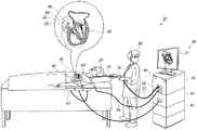
ここで、本発明の一実施形態に従って構築され動作する医療処置システム20の概略図である図1を参照する。図1のシステム20で使用するためのカテーテル40の概略図である図2も参照する。
Description of the System Here, reference is made to FIG. 1, which is a schematic diagram of a medical procedure system 20 constructed and operated according to an embodiment of the present invention. See also FIG. 2, which is a schematic diagram of the
医療処置システム20は、図1の挿入図25に示され、図2により詳細に示されているカテーテル40の位置を判定するために使用される。カテーテル40は、シャフト22と、生存被験者の身体部分に挿入するための複数の偏向可能なアーム54(簡略化のために一部のみに標識されている)を含む。偏向可能なアーム54は、シャフト22の遠位端に接続されたそれぞれの近位端を有する。
The medical procedure system 20 is used to determine the position of the
カテーテル40は、偏向可能なアーム54の近位端に対して所定の空間関係でシャフト22上に配置された位置センサ53を含む。位置センサ53が、磁気センサ50及び/又は少なくとも1つのシャフト電極52を含んでもよい。磁気センサ50が、回転を含む位置及び向きの位置データを提供するための、限定はしないが例えば二軸コイル配列又は三軸コイル配列などの少なくとも1つのコイルを含んでもよい。カテーテル40は、偏向可能なアーム54の各々に沿った異なるそれぞれの位置に配置された複数の電極55(簡略化のために図2では一部のみに標識されている)を含む。典型的には、カテーテル40は、電極55を使用して生存被験者の心臓内の電気活動をマッピングするために、又は生存被験者の身体部分内で任意の他の好適な機能、例えば、可逆的及び/又不可逆的電気穿孔及び/又はRFアブレーションを行うために使用されてもよいが、これらに限られない。
The
医療処置システム20は、カテーテル40のシャフト22の位置及び向きを、磁気センサ50及び/又はシャフト22に取り付けられた磁気センサ50の両側のシャフト電極52(近位電極52a及び遠位電極52b)によって供給される信号に基づいて判定してもよい。近位電極52a、遠位電極52b、磁気センサ50及び少なくともいくつかの電極55は、シャフト22を通って延びるワイヤにより、カテーテルコネクタ35を介してコンソール24内の様々なドライバ回路に接続されている。いくつかの実施形態では、偏向可能なアーム54の各々の少なくとも2つの電極55、シャフト電極52、及び磁気センサ50は、カテーテルコネクタ35を介してコンソール24内のドライバ回路に接続されている。いくつかの実施形態では、遠位電極52b及び/又は近位電極52aは省略されてもよい。
The medical treatment system 20 positions and orients the
図2に示されている図は、純粋に概念を明確化する目的のために選択されている。シャフト電極52及び電極55の他の構成も可能である。位置センサ53に更なる機能が含まれてもよい。明確にするために、灌漑ポートなど、本発明の開示された実施形態に関連しない要素は省略されている。
The figure shown in FIG. 2 is selected purely for the purpose of clarifying the concept. Other configurations of the shaft electrode 52 and the
医師30は、カテーテル40の近位端の近くのマニピュレータ32を使用してシャフト22を操作すること及び/又はシース23からの偏向によって、カテーテル40を患者28の身体部分(例えば心臓26)内の標的位置に誘導する。カテーテル40は、偏向可能なアーム54が集まった状態で、シース23を通して挿入され、カテーテル40がシース23から後退した後にのみ、偏向可能なアーム54が広がり、それらの意図された機能的形状を回復することができる。偏向可能なアーム54をまとめて収容することにより、シース23は、標的位置へ向かう間の血管外傷を最小限に抑える役割も果たす。
Physician 30 uses a manipulator 32 near the proximal end of the
コンソール24は、処理回路41、典型的には汎用コンピュータと、ケーブル39を通って患者28の胸部及び背部又は任意の他の好適な皮膚表面に延びるワイヤによって取り付けられた身体表面電極49において信号を生成する、及び/又は身体表面電極49から信号を受信するための好適なフロントエンド及びインタフェース回路44と、を含む。
The console 24 signals at a
コンソール24は、磁気感知サブシステムを更に備える。患者28は、少なくとも1つの磁界放射器42を含むパッドによって生成された磁界内に置かれ、この磁界放射器42は、コンソール24に配置されたユニット43によって駆動される。磁界放射器(単数又は複数)42は、身体部(例えば心臓26)が配置されている領域に交番磁界を送信するように構成されている。磁界放射器(単数又は複数)42によって生成された磁界は、磁気センサ50において方向信号を生成する。磁気センサ50は、送信された交番磁界の少なくとも一部を検出し、対応する電気入力として方向信号を処理回路41に供給するように構成されている。
The console 24 further comprises a magnetic sensing subsystem. The
いくつかの実施形態では、処理回路41は、シャフト電極52、磁気センサ50及び電極55から受信した位置信号を使用して、心室内などの器官内のカテーテル40の位置を推定する。いくつかの実施形態では、処理回路41は、電極52及び電極55から受信した位置信号を以前に取得した磁気位置較正位置信号と相関させて、心室内のカテーテル40の位置を推定する。シャフト電極52及び電極55の位置座標は、他の入力の中でも特に、電極52、電極55と身体表面電極49との間で測定されるインピーダンス又は電流分布の割合に基づいて、処理回路41によって判定され得る。コンソール24は、心臓26内のカテーテル40の遠位端を示すディスプレイ27を駆動する。
In some embodiments, the
電流分布測定値及び/又は外部磁界を使用する位置検知の方法は、様々な医療用途で、例えば、Biosense Webster Inc.(Irvine,California)により製造されるCarto(登録商標)システムに実装されており、米国特許第5,391,199号、同第6,690,963号、同第6,484,118号、同第6,239,724号、同第6,618,612号、同第6,332,089号、同第7,756,576号、同第7,869,865号、及び同第7,848,787号、国際公開第96/05768号、並びに米国特許出願公開第2002/0065455(A1)号、同第2003/0120150(A1)号、及び同第2004/0068178(A1)号に詳述されている。 Position detection methods using current distribution measurements and / or external magnetic fields have been used in a variety of medical applications, such as Biosense Webster Inc. It is implemented in a Carto® system manufactured by (Irvine, California), and is implemented in US Pat. Nos. 5,391,199, 6,690,963, 6,484,118, and 6,484,118. No. 6,239,724, No. 6,618,612, No. 6,332,089, No. 7,756,576, No. 7,869,865, and No. 7,848. , 787, WO 96/05768, and US Patent Application Publication Nos. 2002/0065455 (A1), 2003/0120150 (A1), and 2004/0068178 (A1). ing.
Carto(登録商標)3システムは、有効電流位置(ACL)のインピーダンスベースの位置追跡方法を適用する。いくつかの実施形態では、処理回路41は、ACL法を使用して、電気インピーダンスの表示と磁界放射器(単数又は複数)42の磁気座標フレーム内の位置との間のマッピング(例えば、現在位置マトリックス(CPM))を作成するように構成されている。処理回路41は、CPM内でルックアップを実行することにより、シャフト電極52及び電極55の位置を推定する。
The Carto® 3 system applies an impedance-based position tracking method for active current positions (ACLs). In some embodiments, the
カテーテルの遠位端の位置を判定する他の方法は、例えば、超音波トランスデューサ及び受信機に基づいて、超音波又はMRI又はCTスキャンなどの撮像技術を使用して使用することができ、これは、カテーテル40上に放射線不透過性タグを配置することを含み得る。
Other methods of determining the location of the distal end of the catheter can be used using imaging techniques such as ultrasound or MRI or CT scans, based on, for example, ultrasound transducers and receivers, which can be used. , May include placing a radiopaque tag on the
処理回路41は、本明細書に記載される機能を実行するために、典型的にはソフトウェアでプログラムされる。ソフトウェアは、例えばネットワーク上で、コンピュータに電子形態でダウンロードすることができるか、又は代替的に若しくは追加的に、磁気メモリ、光学メモリ若しくは電子メモリなどの、非一時的な有形媒体上に提供及び/若しくは記憶されてもよい。
The
図1は、簡潔性かつ明瞭性のために、開示される技術に関する要素のみを示す。システム20は、典型的には、開示される技術には直接関連しないために図1及び対応する説明から意図的に省略されている、追加のモジュール及び要素を備える。 FIG. 1 shows only the disclosed technology elements for brevity and clarity. The system 20 typically comprises additional modules and elements that are deliberately omitted from FIG. 1 and the corresponding description because they are not directly related to the disclosed technology.
上述のカテーテル40は、アーム54ごとに6つの電極を有する8つの偏向可能なアーム54を含む。カテーテル40の代わりに、例えば、様々な数の可撓性アーム及び/又はアームごとに複数の電極を有するカテーテルなどの任意の好適なカテーテル、あるいは、例としてではあるが、バルーンカテーテル又はラッソカテーテルなどの様々なプローブ形状を使用してもよい。
The
医療処置システム20はまた、任意の好適なカテーテル、例えば、カテーテル40又はこれとは異なるカテーテル及び任意の好適なアブレーション方法を使用して、心臓組織の電気穿孔又はRFアブレーション(若しくは他のアブレーション技術)を行ってもよい。コンソール24は、心臓26の心筋のアブレーションの電気穿孔を行うために、コンソール24に接続されたカテーテルの電極(単数又は複数)(及び、任意で、身体表面電極49のうちの1つ以上)によって印加される電気信号を生成するように構成されている信号生成器34を含んでもよい。コンソール24は、RFアブレーションを行っているカテーテルの遠位端への灌注チャネルに灌注流体を圧送するポンプ(図示せず)を含んでもよい。RFアブレーションを行うカテーテルは、RFアブレーション中に心筋の温度を測定し、測定された温度に従ってアブレーション電力及び/又は灌注流体の圧送の灌注速度を調節するために使用される温度センサ(図示せず)を更に含んでもよい。
The medical procedure system 20 also uses any suitable catheter, such as the
ここで、図1の医療処置システム20の操作方法における工程を含むフローチャート60である図3を参照する。
Here, reference is made to FIG. 3, which is a
カテーテル40(図1)は、心臓26の心室(図1)に挿入される(ブロック62)ように構成されている。 The catheter 40 (FIG. 1) is configured to be inserted into the ventricle (FIG. 1) of the heart 26 (block 62).
信号生成器34(図1)は、カテーテル40の電極55のうちの少なくとも2つの電極(図2)に結合されている。信号生成器34は、電極55のうちの少なくとも2つの電極に供給するための電気信号を生成する(ブロック64)ように構成されており、少なくとも2つの電極は、電気信号に応答して、心室内の所与の位置において、心臓26の心室の組織に電界を印加する。電界は、可逆的電気穿孔を引き起こすのに十分であるが、不可逆的電気穿孔の閾値を下回る振幅を有する。電界は、電極55のうちの任意の2つの電極の間、例えば隣接する電極55の間に、及び/又は電極55のうちのいくつかと電極55の参照電極との間に、印加されてもよい。所与の場所で電極55によって組織に印加される電界は、一般に、1センチメートル当たり450ボルト未満である。信号生成器34によって供給される電気信号は、パルス電気信号であってもよい。パルス電気信号は、一連の二相パルスを含んでもよく、各二相パルスは、正相パルス及び逆相パルスを含む。例えば、一連の二相パルスは、2マイクロ秒の正相パルス、続いて0.5マイクロ秒の遅延、続いて、2マイクロ秒の逆相パルスなどを含んでもよい。パルス電気信号は、一連のバーストを含んでもよく、各バーストは、二相パルス又は単相パルスなどの一連のパルスを含む。パルスの各々は、例えば、1〜20マイクロ秒の任意の好適な長さを有してもよい。一連のバーストは、例えば100マイクロ秒〜1000ミリ秒の任意の好適な長さのバースト間のギャップを含む。各バーストは、任意の好適な数のパルス、例えば、最大100個のパルスを含んでもよい。一連のバーストは、任意の好適な数のバースト、例えば、最大100個のバーストを含んでもよい。
The signal generator 34 (FIG. 1) is coupled to at least two of the
電気信号の様々なパラメータ(振幅、パルス長、ギャップ、並びにパルス及びバーストの数など)は、周囲組織を実質的に加熱することなく、組織内に可逆的電気穿孔を少なくとも2〜3mmの深さまで引き起こす電界を提供するように好適に調整されてもよい。「周囲組織を実質的に加熱することなく」という用語は、明細書及び特許請求の範囲で使用されるとき、臨床効果がないレベルまで組織を加熱することとして定義される。いくつかの用途では、温度の摂氏3度の上昇は、電気穿孔で使用される持続時間に対して許容され得る。 Various parameters of the electrical signal (amplitude, pulse length, gap, and number of pulses and bursts, etc.) allow reversible electroporation within the tissue to a depth of at least 2-3 mm without substantially heating the surrounding tissue. It may be suitably adjusted to provide an electric field that causes it. The term "without substantially heating the surrounding tissue" is defined as heating the tissue to a level that has no clinical effect when used in the specification and claims. In some applications, an increase in temperature of 3 degrees Celsius can be tolerated for the duration used in electroporation.
電界が印加されている期間中、又は実質的にその直後に、電界が印加されていた/されている位置の近傍で心臓26の心室の組織における電気的活性化信号に対する可逆的電気穿孔の効果が測定される。
The effect of reversible electroporation on the electrical activation signal in the ventricular tissue of the
処理回路41は、その位置の近傍で心臓26の心室の組織における電気的活性化信号をカテーテル40から受信する(ブロック66)ように構成されている。
The
処理回路41は、その位置の近傍で心臓26の心室の組織における電気的活性化信号に対する可逆的電気穿孔の効果を測定する(ブロック68)ように構成されている。可逆的電気穿孔の効果を測定することは、その位置の近傍から捕捉された信号の振幅を測定すること、並びに/あるいは、信号を処理して信号のグラフを生成すること、及び/又は電気的活性化信号に基づいて、電気解剖学的マップを生成すること、を含んでもよい。位置の「近傍」は、可逆的電気穿孔が行われる位置内及び/又はその周囲であってもよい。
The
したがって、いくつかの実施形態では、処理回路41は、電気的活性化信号に応答して、心臓の心室の電気解剖学的マップを生成する(ブロック70)ように構成されている。ブロック70の工程について、図5を参照して以下により詳述する。
Therefore, in some embodiments, the
処理回路41は、その位置の近傍で心臓の心室の組織における電気的活性化信号の表示をディスプレイ27にレンダリングする(ブロック72)ように構成されている。表示は、活性化信号の振幅(単数又は複数)、活性化信号のグラフ(単数又は複数)、又は活性化信号を表す電気解剖学的マップを含んでもよい。
The
いくつかの実施形態では、組織内に可逆的電気穿孔を誘導する前、最中、又は後に、物質が組織に適用されてもよく、可逆的電気穿孔及び電気的活性化信号に対する物質の効果が検査されてもよい。 In some embodiments, the material may be applied to the tissue before, during, or after inducing reversible electroporation within the tissue, and the effect of the material on reversible electroporation and electrical activation signals. It may be inspected.
ここで、図1のシステム20によって生成された心内電位図80の概略図である図4を参照する。心内電位図80−1、80−2は、処理回路41(図1)によってディスプレイ27にレンダリングされ、可逆的電気穿孔が適用される前(心内電位図80−1に示される)と、可逆的電気穿孔が適用されている最中又は実質的に適用された直後(心臓内電位図80−2に示される)の可逆的電気穿孔の位置の周囲のポイントで捕捉された電気的活性化信号を表す。可逆的電気穿孔は、その位置の周囲のポイントでの電気的活性を低下させる効果があったことが分かる。
Here, reference is made to FIG. 4, which is a schematic view of the intracardiac potential FIG. 80 generated by the system 20 of FIG. The electrocardiographic potentials 80-1 and 80-2 were rendered on the
ここで、図1のシステム20によって生成された電気解剖学的マップ82の概略図である図5を参照する。図3もまた参照する。
Here, reference is made to FIG. 5, which is a schematic view of the
処理回路41(図1)は、心臓26の心室(単数又は複数)の表面上の複数のサンプル位置でカテーテル40(図1)によって経時的に捕捉された電気的活性化信号を処理して、心臓26の心室(単数又は複数)の表面上の複数の位置でのそれぞれの活性化時間を判定するように構成されている。処理回路41は、複数の活性化時間と関連付けられた複数の活性化波面の伝播を記載する(簡略化のために一部のみに標識されている)複数の速度ベクトル84を含む電気解剖学的マップ82を用意するように構成されている。電気解剖学的マップ82を用意するための1つの方法は、米国特許第6,301,496号に記載されている。電気解剖学的マップ82を用意するための任意の好適な方法が使用されてもよい。他の電気解剖学的マップは、例えば、色を使用して活性化時間を示すように生成されてもよい。
Processing circuit 41 (FIG. 1) processes electrical activation signals captured over time by catheter 40 (FIG. 1) at multiple sample locations on the surface of the ventricles (s) of
処理回路41は、電気解剖学的マップ82をディスプレイ27にレンダリングする(ブロック74)ように構成されている。電気解剖学的マップ82は、可逆的電気穿孔の効果を更に可視化するために、可逆的電気穿孔が行われる前の心臓26の心室(単数又は複数)の電気的活性を表す別の電気解剖学的マップと並べて表示されてもよい。
The
再び図3を参照する。医師は、心内電位図80(図4)及び/又は電気解剖学的マップ82(図5)又は他のデータを検査して、可逆的電気穿孔が適用された位置をIRE又は別のアブレーション技術を使用して永続的にアブレーションすべきか、あるいは全くアブレーションしないべきかを判定する。医師が永続的にアブレーションすることと決定した場合、医師は、システム20を操作してアブレーションを行う。信号生成器34(図1)は、電極55のうちの少なくとも2つの電極に供給するための別の電気信号を生成するように構成されており、電極55のうちの少なくとも2つの電極は、別の電気信号に応答して、心室内の位置において、心臓26(図1)の心室の組織に不可逆的電気穿孔を引き起こすのに十分な振幅を有する別の電界を印加する(ブロック76)。代替的には、医師は、その加熱効果により、組織の細胞を死滅させるRFアブレーションなどの別の形態のアブレーションを使用することができる。
See FIG. 3 again. The physician examines the electrocardiographic potential diagram 80 (FIG. 4) and / or the electroanatomical map 82 (FIG. 5) or other data to determine where reversible electroporation has been applied by IRE or another ablation technique. To determine if it should be ablated permanently or not at all. If the physician decides to ablate permanently, the physician operates the system 20 to perform the ablation. The signal generator 34 (FIG. 1) is configured to generate another electrical signal to supply to at least two of the
電界は、電極55のうちの任意の2つの電極の間、例えば隣接する電極55の間に、及び/又は電極55のうちのいくつかと電極55の参照電極との間に、印加されてもよい。所与の位置で電極55によって組織に印加される電界は、一般に1センチメートル当たり800ボルトを超える。信号生成器34によって供給される電気信号は、パルス電気信号であってもよい。パルス電気信号は、一連の二相パルスを含んでもよく、各二相パルスは、正相パルス及び逆相パルスを含む。例えば、一連の二相パルスは、2マイクロ秒の正相パルス、続いて0.5マイクロ秒の遅延、続いて、2マイクロ秒の逆相パルスなどを含んでもよい。パルス電気信号は、一連のバーストを含んでもよく、各バーストは、二相パルス又は単相パルスなどの一連のパルスを含む。パルスの各々は、例えば、1〜20マイクロ秒の任意の好適な長さを有してもよい。一連のバーストは、例えば100マイクロ秒〜1000ミリ秒の任意の好適な長さのバースト間のギャップを含む。各バーストは、任意の好適な数のパルス、例えば、最大100個のパルスを含んでもよい。一連のバーストは、任意の好適な数のバースト、例えば、最大100個のバーストを含んでもよい。電気信号の様々なパラメータ(振幅、パルス長、ギャップ、並びにパルス及びバーストの数など)は、周囲組織を実質的に加熱することなく、組織内にIRE及び損傷を少なくとも2〜3mmの深さまで引き起こす電界を提供するように好適に調節されてもよい。
An electric field may be applied between any two of the
本明細書で任意の数値又は数値の範囲について用いる「約」又は「およそ」という用語は、構成要素の部分又は構成要素の集合が、本明細書において説明されるその意図された目的に沿って機能することを可能とする、好適な寸法の許容誤差を示すものである。より具体的には、「約」又は「およそ」とは、列挙された値の±20%の値の範囲を指してもよく、例えば「約90%」は、71%〜99%の値の範囲を指してもよい。 The term "about" or "approximately" as used herein for any number or range of numbers means that a component or set of components is in line with its intended purpose as described herein. It indicates a suitable dimensional tolerance that allows it to function. More specifically, "about" or "approximately" may refer to a range of values ± 20% of the listed values, for example "about 90%" is a value of 71% to 99%. You may point to a range.
本発明の様々な特徴が、明確性のために別個の実施形態の文脈において記載されているが、これらが単一の実施形態に組み合わされて提供されてもよい。逆に、簡潔にするために単一の実施形態の文脈において記載されている本発明の様々な特徴が、別々に又は任意の好適な部分的組み合わせで提供されてもよい。 Although various features of the invention are described in the context of separate embodiments for clarity, they may be provided in combination in a single embodiment. Conversely, the various features of the invention described in the context of a single embodiment for brevity may be provided separately or in any suitable partial combination.
上に記載される実施形態は、例として引用されており、本発明は、上記の明細書に具体的に図示及び記載されたものによって限定されない。むしろ、本発明の範囲は、上記の明細書に記載された様々な特徴のコンビネーション及びサブコンビネーションの両方、並びに前述の記載を読むと当業者が思い付くであろうが、先行技術に開示されていないその変形及び修正を含む。 The embodiments described above are cited as examples, and the invention is not limited to those specifically illustrated and described herein. Rather, the scope of the invention is not disclosed in the prior art, as one of ordinary skill in the art would come up with, as well as both combinations and subcombinations of the various features described herein above. Includes its modifications and modifications.
〔実施の態様〕
(1) 電気穿孔法であって、
複数の電極を有するカテーテルを心臓の心室に挿入することと、
前記心室内の所与の位置において、前記心臓の前記心室の組織に、前記電極のうちの少なくとも2つの電極を使用して、可逆的電気穿孔を引き起こすのに十分であるが、不可逆的電気穿孔の閾値を下回る振幅を有する電界を印加することと、
前記位置の近傍で前記心臓の前記心室の前記組織における電気的活性化信号に対する前記可逆的電気穿孔の効果を測定することと、
を含む、方法。
(2) 前記電界は、1センチメートル当たり450ボルト未満である、実施態様1に記載の方法。
(3) パルス電気信号を生成することを更に含み、前記電界を印加することは、生成された前記パルス電気信号に応答して、前記少なくとも2つの電極を使用して前記電界を印加することを含む、実施態様2に記載の方法。
(4) 前記パルス電気信号は、一連の二相パルスを含み、各二相パルスは、正相パルス及び逆相パルスを含む、実施態様3に記載の方法。
(5) 前記パルス電気信号は、一連のバーストを含み、各バーストは、一連のパルスを含む、実施態様3に記載の方法。
[Implementation mode]
(1) Electroporation method
Inserting a catheter with multiple electrodes into the ventricles of the heart,
At a given location in the ventricle, the tissue of the ventricle of the heart is sufficient to cause reversible electroporation using at least two of the electrodes, but irreversible electroporation. Applying an electric field with an amplitude below the threshold of
To measure the effect of the reversible electroporation on an electrical activation signal in the tissue of the ventricle of the heart in the vicinity of the location.
Including methods.
(2) The method according to embodiment 1, wherein the electric field is less than 450 volts per centimeter.
(3) Further including generating a pulsed electrical signal, applying the electric field means applying the electric field using the at least two electrodes in response to the generated pulsed electrical signal. The method according to embodiment 2, which includes.
(4) The method according to the third embodiment, wherein the pulsed electrical signal includes a series of two-phase pulses, and each two-phase pulse includes a positive-phase pulse and a negative-phase pulse.
(5) The method of embodiment 3, wherein the pulsed electrical signal comprises a series of bursts, each burst comprising a series of pulses.
(6) 前記パルスの各々は、1〜20マイクロ秒のパルス長を有し、前記一連のバーストは、100マイクロ秒〜1000ミリ秒のバースト間のギャップを含む、実施態様5に記載の方法。
(7) 各バーストは、最大100個の前記パルスを含み、前記一連のバーストは、最大100個のバーストを含む、実施態様6に記載の方法。
(8) 前記位置の前記近傍で前記心臓の前記心室の前記組織における前記電気的活性化信号の表示をディスプレイにレンダリングすることと、
前記心室内の前記所定の位置において、前記心臓の前記心室の前記組織に、前記電極のうちの少なくとも2つの電極を使用して、不可逆的電気穿孔を引き起こすのに十分な振幅を有する別の電界を印加することと、を更に含む、実施態様1に記載の方法。
(9) 前記電気的活性化信号に応答して、前記心臓の前記心室の電気解剖学的マップを生成することと、
前記電気解剖学的マップを前記ディスプレイにレンダリングすることと、
を更に含む、実施態様8に記載の方法。
(10) 可逆的電気穿孔を引き起こすのに十分であるが、不可逆的電気穿孔の閾値を下回る前記振幅を有する前記電界は、1センチメートル当たり450ボルト未満であり、不可逆的電気穿孔を引き起こすのに十分な前記振幅を有する前記別の電界は、1センチメートル当たり800ボルトを超える、実施態様8に記載の方法。
(6) The method of embodiment 5, wherein each of the pulses has a pulse length of 1 to 20 microseconds, and the series of bursts comprises a gap between bursts of 100 microseconds to 1000 milliseconds.
(7) The method of embodiment 6, wherein each burst comprises up to 100 of the pulses, and the series of bursts comprises up to 100 bursts.
(8) Rendering the display of the electrical activation signal in the tissue of the ventricle of the heart in the vicinity of the position on the display.
At the predetermined location in the ventricle, another electric field having sufficient amplitude to cause irreversible electroporation in the tissue of the ventricle of the heart using at least two of the electrodes. The method according to the first embodiment, further comprising the application of.
(9) To generate an electroanatomical map of the ventricles of the heart in response to the electrical activation signal.
Rendering the electroanatomical map on the display and
The method according to embodiment 8, further comprising.
(10) The electric field, which is sufficient to cause reversible electroporation but has the amplitude below the threshold of irreversible electroporation, is less than 450 volts per centimeter to cause irreversible electroporation. 8. The method of embodiment 8, wherein the other electric field having sufficient said amplitude exceeds 800 volts per centimeter.
(11) パルス電気信号を生成することを更に含み、前記別の電界を印加することが、生成された前記パルス電気信号に応答して、前記少なくとも2つの電極を使用して前記別の電界を印加することを含む、実施態様10に記載の方法。
(12) 前記パルス電気信号は、一連の二相パルスを含み、各二相パルスは、正相パルス及び逆相パルスを含む、実施態様11に記載の方法。
(13) 前記パルス電気信号は、一連のバーストを含み、各バーストは、一連のパルスを含む、実施態様11に記載の方法。
(14) 前記パルスの各々は、1〜20マイクロ秒のパルス長を有し、前記一連のバーストは、100マイクロ秒〜1000ミリ秒のバースト間のギャップを含む、実施態様13に記載の方法。
(15) 各バーストは、最大100個の前記パルスを含み、前記一連のバーストは、最大100個のバーストを含む、実施態様14に記載の方法。
(11) Further including generating a pulsed electrical signal, applying the other electric field causes the other electric field to be generated using the at least two electrodes in response to the generated pulsed electrical signal. 10. The method of embodiment 10, comprising applying.
(12) The method according to embodiment 11, wherein the pulsed electrical signal includes a series of two-phase pulses, each two-phase pulse including a positive-phase pulse and a negative-phase pulse.
(13) The method of embodiment 11, wherein the pulsed electrical signal comprises a series of bursts, each burst comprising a series of pulses.
(14) The method of embodiment 13, wherein each of the pulses has a pulse length of 1 to 20 microseconds, and the series of bursts comprises a gap between bursts of 100 microseconds to 1000 milliseconds.
(15) The method of embodiment 14, wherein each burst comprises up to 100 of the pulses, and the series of bursts comprises up to 100 bursts.
(16) 電気穿孔システムであって、
複数の電極を含み、かつ、心臓の心室に挿入されるように構成されている、カテーテルと、
前記電極のうちの少なくとも2つの電極に結合され、かつ、前記少なくとも2つの電極に供給するための電気信号を生成するように構成されている、信号生成器であって、前記少なくとも2つの電極は、前記電気信号に応答して、前記心臓の前記心室内の所与の位置において、前記心室の組織に電界を印加し、前記電界は、可逆的電気穿孔を引き起こすのに十分であるが、不可逆的電気穿孔の閾値を下回る振幅を有する、信号生成器と、
前記位置の近傍で前記心臓の前記心室の前記組織における電気的活性化信号を前記カテーテルから受信し、前記位置の近傍で前記心臓の前記心室の前記組織における前記電気的活性化信号に対する前記可逆的電気穿孔の効果を測定する、ように構成されている処理回路と、
を含む、電気穿孔システム。
(17) 前記電界は、1センチメートル当たり450ボルト未満である、実施態様16に記載のシステム。
(18) 前記電気信号は、パルス電気信号である、実施態様17に記載のシステム。
(19) 前記パルス電気信号は、一連の二相パルスを含み、各二相パルスは、正相パルス及び逆相パルスを含む、実施態様17に記載のシステム。
(20) 前記パルス電気信号は、一連のバーストを含み、各バーストは、一連のパルスを含む、実施態様17に記載のシステム。
(16) Electroporation system
A catheter that contains multiple electrodes and is configured to be inserted into the ventricles of the heart.
A signal generator that is coupled to at least two of the electrodes and is configured to generate an electrical signal to supply to the at least two electrodes, wherein the at least two electrodes are In response to the electrical signal, at a given location in the ventricle of the heart, an electric field is applied to the tissue of the ventricle, which is sufficient to cause reversible electrical perforation, but irreversible. With a signal generator that has an amplitude below the threshold of the target electric perforation,
In the vicinity of the location, the electrical activation signal in the tissue of the ventricle of the heart is received from the catheter, and in the vicinity of the location, the reversible signal to the electrical activation signal in the tissue of the ventricle of the heart. With a processing circuit configured to measure the effect of electrical drilling,
Including electroporation system.
(17) The system according to embodiment 16, wherein the electric field is less than 450 volts per centimeter.
(18) The system according to embodiment 17, wherein the electrical signal is a pulsed electrical signal.
(19) The system according to embodiment 17, wherein the pulsed electrical signal includes a series of two-phase pulses, each two-phase pulse including a positive-phase pulse and a negative-phase pulse.
(20) The system according to embodiment 17, wherein the pulsed electrical signal comprises a series of bursts, each burst comprising a series of pulses.
(21) 前記パルスの各々は、1〜20マイクロ秒のパルス長を有し、前記一連のバーストは、100マイクロ秒〜1000ミリ秒のバースト間のギャップを含む、実施態様20に記載のシステム。
(22) 各バーストは、最大100個の前記パルスを含み、前記一連のバーストは、最大100個のバーストを含む、実施態様21に記載のシステム。
(23) 前記処理回路は、前記位置の前記近傍で前記心臓の前記心室の前記組織における前記電気的活性化信号の表示をディスプレイにレンダリングするように構成されており、
前記信号生成器は、前記電極のうちの少なくとも2つの電極に供給するための別の電気信号を生成するように構成されており、前記電極のうちの少なくとも2つの電極は、前記別の電気信号に応答して、前記心臓の前記心室内の前記位置において、前記心室の組織に、不可逆的電気穿孔を引き起こすのに十分な振幅を有する別の電界を印加する、実施態様16に記載のシステム。
(24) 前記処理回路は、
前記電気的活性化信号に応答して、前記心臓の前記心室の電気解剖学的マップを生成することと、
前記電気解剖学的マップを前記ディスプレイにレンダリングすることと、
を行うように構成されている、実施態様23に記載のシステム。
(25) 可逆的電気穿孔を引き起こすのに十分であるが、不可逆的電気穿孔の閾値を下回る前記振幅を有する前記電界は、1センチメートル当たり450ボルト未満であり、不可逆的電気穿孔を引き起こすのに十分な前記振幅を有する前記別の電界は、1センチメートル当たり800ボルトを超える、実施態様23に記載のシステム。
(21) The system of embodiment 20, wherein each of the pulses has a pulse length of 1 to 20 microseconds, and the series of bursts comprises a gap between bursts of 100 microseconds to 1000 milliseconds.
(22) The system of embodiment 21, wherein each burst comprises up to 100 of the pulses, and the series of bursts comprises up to 100 bursts.
(23) The processing circuit is configured to render on a display the display of the electrical activation signal in the tissue of the ventricles of the heart in the vicinity of the location.
The signal generator is configured to generate another electrical signal to supply to at least two of the electrodes, and at least two of the electrodes have the other electrical signal. 16. The system of embodiment 16, wherein another electric field having sufficient amplitude to cause an irreversible electrical perforation is applied to the tissue of the ventricle at the location of the ventricle of the heart in response to.
(24) The processing circuit is
To generate an electroanatomical map of the ventricles of the heart in response to the electrical activation signal.
Rendering the electroanatomical map on the display and
23. The system according to embodiment 23, which is configured to perform the above.
(25) The electric field, which is sufficient to cause reversible electroporation but has the amplitude below the threshold of irreversible electroporation, is less than 450 volts per centimeter to cause irreversible electroporation. 23. The system of embodiment 23, wherein the other electric field having sufficient said amplitude exceeds 800 volts per centimeter.
(26) 前記別の電気信号が、パルス電気信号である、実施態様25に記載のシステム。
(27) 前記パルス電気信号は、一連の二相パルスを含み、各二相パルスは、正相パルス及び逆相パルスを含む、実施態様26に記載のシステム。
(28) 前記パルス電気信号は、一連のバーストを含み、各バーストは、一連のパルスを含む、実施態様26に記載のシステム。
(29) 前記パルスの各々は、1〜20マイクロ秒のパルス長を有し、前記一連のバーストは、100マイクロ秒〜1000ミリ秒のバースト間のギャップを含む、実施態様28に記載のシステム。
(30) 各バーストは、最大100個の前記パルスを含み、前記一連のバーストは、最大100個のバーストを含む、実施態様29に記載のシステム。
(26) The system according to
(27) The system according to
(28) The system of
(29) The system of
(30) The system of embodiment 29, wherein each burst comprises up to 100 of the pulses, and the series of bursts comprises up to 100 bursts.
Claims (15)
複数の電極を含み、かつ、心臓の心室に挿入されるように構成されている、カテーテルと、
前記電極のうちの少なくとも2つの電極に結合され、かつ、前記少なくとも2つの電極に供給するための電気信号を生成するように構成されている、信号生成器であって、前記少なくとも2つの電極は、前記電気信号に応答して、前記心臓の前記心室内の所与の位置において、前記心室の組織に電界を印加し、前記電界は、可逆的電気穿孔を引き起こすのに十分であるが、不可逆的電気穿孔の閾値を下回る振幅を有する、信号生成器と、
前記位置の近傍で前記心臓の前記心室の前記組織における電気的活性化信号を前記カテーテルから受信し、前記位置の近傍で前記心臓の前記心室の前記組織における前記電気的活性化信号に対する前記可逆的電気穿孔の効果を測定する、ように構成されている処理回路と、
を含む、電気穿孔システム。 Electroporation system
A catheter that contains multiple electrodes and is configured to be inserted into the ventricles of the heart.
A signal generator that is coupled to at least two of the electrodes and is configured to generate an electrical signal to supply to the at least two electrodes, wherein the at least two electrodes are In response to the electrical signal, at a given location in the ventricle of the heart, an electric field is applied to the tissue of the ventricle, which is sufficient to cause reversible electrical perforation, but irreversible. With a signal generator that has an amplitude below the threshold of the target electric perforation,
In the vicinity of the location, the electrical activation signal in the tissue of the ventricle of the heart is received from the catheter, and in the vicinity of the location, the reversible signal to the electrical activation signal in the tissue of the ventricle of the heart. With a processing circuit configured to measure the effect of electrical drilling,
Including electroporation system.
前記信号生成器は、前記電極のうちの少なくとも2つの電極に供給するための別の電気信号を生成するように構成されており、前記電極のうちの少なくとも2つの電極は、前記別の電気信号に応答して、前記心臓の前記心室内の前記位置において、前記心室の組織に、不可逆的電気穿孔を引き起こすのに十分な振幅を有する別の電界を印加する、請求項1に記載のシステム。 The processing circuit is configured to render on a display the display of the electrical activation signal in the tissue of the ventricle of the heart in the vicinity of the location.
The signal generator is configured to generate another electrical signal to supply to at least two of the electrodes, and at least two of the electrodes have the other electrical signal. The system of claim 1, wherein in response to, at the location in the ventricle of the heart, another electric field having sufficient amplitude to cause an irreversible electrical perforation is applied to the tissue of the ventricle.
前記電気的活性化信号に応答して、前記心臓の前記心室の電気解剖学的マップを生成することと、
前記電気解剖学的マップを前記ディスプレイにレンダリングすることと、
を行うように構成されている、請求項8に記載のシステム。 The processing circuit
To generate an electroanatomical map of the ventricles of the heart in response to the electrical activation signal.
Rendering the electroanatomical map on the display and
8. The system of claim 8.
Applications Claiming Priority (4)
| Application Number | Priority Date | Filing Date | Title |
|---|---|---|---|
| US201962942999P | 2019-12-03 | 2019-12-03 | |
| US62/942,999 | 2019-12-03 | ||
| US16/921,578 US20210162210A1 (en) | 2019-12-03 | 2020-07-06 | Using reversible electroporation on cardiac tissue |
| US16/921,578 | 2020-07-06 |
Publications (1)
| Publication Number | Publication Date |
|---|---|
| JP2021087778A true JP2021087778A (en) | 2021-06-10 |
Family
ID=73694822
Family Applications (1)
| Application Number | Title | Priority Date | Filing Date |
|---|---|---|---|
| JP2020200091A Pending JP2021087778A (en) | 2019-12-03 | 2020-12-02 | Using reversible electroporation on cardiac tissue |
Country Status (5)
| Country | Link |
|---|---|
| US (1) | US20210162210A1 (en) |
| EP (1) | EP3831442A1 (en) |
| JP (1) | JP2021087778A (en) |
| CN (1) | CN112890947A (en) |
| IL (1) | IL278896A (en) |
Families Citing this family (17)
| Publication number | Priority date | Publication date | Assignee | Title |
|---|---|---|---|---|
| US20230226336A1 (en) | 2022-01-20 | 2023-07-20 | Biosense Webster (Israel) Ltd. | Electrode assemblies of a basket catheter having mechanical retainers and methods of the same |
| US20230225787A1 (en) | 2022-01-20 | 2023-07-20 | Biosense Webster (Israel) Ltd. | Systems and methods for linear spines forming a spherical basket for improved tissue contact and current delivery |
| US20230225788A1 (en) | 2022-01-20 | 2023-07-20 | Biosense Webster (Israel) Ltd. | Systems and methods for c-shaped spines forming a spherical basket for improved tissue contact and current delivery |
| US20230225790A1 (en) | 2022-01-20 | 2023-07-20 | Biosense Webster (Israel) Ltd. | Mechanical retainer systems for electrodes of a basket catheter, and methods of the same |
| US20230226638A1 (en) | 2022-01-20 | 2023-07-20 | Biosense Webster (Israel) Ltd. | Intravascular device including high voltage coaxial conductor wiring |
| US20230225789A1 (en) | 2022-01-20 | 2023-07-20 | Biosense Webster (Israel) Ltd. | Systems and methods for linear spines and spine retention hub for improved tissue contact and current delivery |
| US20230225784A1 (en) | 2022-01-20 | 2023-07-20 | Biosense Webster (Israel) Ltd. | Systems and methods for tripodic spines forming a spherical basket for improved tissue contact and current delivery |
| US20230225783A1 (en) | 2022-01-20 | 2023-07-20 | Biosense Webster (Israel) Ltd. | Systems and methods for a single spiral electrode assembly forming a spherical basket for improved tissue contact and current delivery |
| US20230301707A1 (en) | 2022-03-25 | 2023-09-28 | Biosense Webster (Israel) Ltd. | Elongated cylindrical electrodes of a basket catheter and methods of making the same |
| US20230301713A1 (en) | 2022-03-25 | 2023-09-28 | Biosense Webster (Israel) Ltd. | Expandable basket assemblies with linear spine patterns for improved tissue contact and methods for making thereof |
| US20230301712A1 (en) | 2022-03-25 | 2023-09-28 | Biosense Webster (Israel) Ltd. | Elongated trapezoidal electrodes of a basket catheter and methods of making the same |
| US20230346466A1 (en) | 2022-04-28 | 2023-11-02 | Biosense Webster (Israel) Ltd. | Basket catheter with cloverleaf structure to provide predetermined lateral stiffness and axial strain |
| US20230346464A1 (en) | 2022-04-28 | 2023-11-02 | Biosense Webster (Israel) Ltd. | Basket catheter with cloverleaf structure to prevent buckling and retention feature for electrodes |
| US20230346455A1 (en) | 2022-04-28 | 2023-11-02 | Biosense Webster (Israel) Ltd. | Basket catheter with force sensor having bayonet mount |
| US20230346461A1 (en) | 2022-04-28 | 2023-11-02 | Biosense Webster (Israel) Ltd. | Systems and devices for improved irrigation flow during cardiac procedure |
| US20230346462A1 (en) | 2022-04-28 | 2023-11-02 | Biosense Webster (Israel) Ltd. | Strengthened expandable baskets for medical probes and medical probes containing strengthen expandable baskets |
| US20230346463A1 (en) | 2022-04-28 | 2023-11-02 | Biosense Webster (Israel) Ltd. | Barrel electrodes for a basket catheter, and methods of the same |
Family Cites Families (29)
| Publication number | Priority date | Publication date | Assignee | Title |
|---|---|---|---|---|
| US5391199A (en) | 1993-07-20 | 1995-02-21 | Biosense, Inc. | Apparatus and method for treating cardiac arrhythmias |
| ES2144123T3 (en) | 1994-08-19 | 2000-06-01 | Biosense Inc | MEDICAL DIAGNOSIS, TREATMENT AND IMAGE SYSTEMS. |
| US6690963B2 (en) | 1995-01-24 | 2004-02-10 | Biosense, Inc. | System for determining the location and orientation of an invasive medical instrument |
| IL125761A (en) | 1996-02-15 | 2005-05-17 | Biosense Inc | Independently positionable transducers for location system |
| AU709081B2 (en) | 1996-02-15 | 1999-08-19 | Biosense, Inc. | Medical procedures and apparatus using intrabody probes |
| US6239724B1 (en) | 1997-12-30 | 2001-05-29 | Remon Medical Technologies, Ltd. | System and method for telemetrically providing intrabody spatial position |
| US6301496B1 (en) | 1998-07-24 | 2001-10-09 | Biosense, Inc. | Vector mapping of three-dimensionally reconstructed intrabody organs and method of display |
| US20020006455A1 (en) | 2000-07-10 | 2002-01-17 | Levine Michael L. | Baby food selection system and method |
| US6484118B1 (en) | 2000-07-20 | 2002-11-19 | Biosense, Inc. | Electromagnetic position single axis system |
| US7729742B2 (en) | 2001-12-21 | 2010-06-01 | Biosense, Inc. | Wireless position sensor |
| US20040068178A1 (en) | 2002-09-17 | 2004-04-08 | Assaf Govari | High-gradient recursive locating system |
| US7937143B2 (en) | 2004-11-02 | 2011-05-03 | Ardian, Inc. | Methods and apparatus for inducing controlled renal neuromodulation |
| US7869865B2 (en) | 2005-01-07 | 2011-01-11 | Biosense Webster, Inc. | Current-based position sensing |
| US7848787B2 (en) | 2005-07-08 | 2010-12-07 | Biosense Webster, Inc. | Relative impedance measurement |
| US20070021803A1 (en) | 2005-07-22 | 2007-01-25 | The Foundry Inc. | Systems and methods for neuromodulation for treatment of pain and other disorders associated with nerve conduction |
| US7756576B2 (en) | 2005-08-26 | 2010-07-13 | Biosense Webster, Inc. | Position sensing and detection of skin impedance |
| US20090247933A1 (en) | 2008-03-27 | 2009-10-01 | The Regents Of The University Of California; Angiodynamics, Inc. | Balloon catheter method for reducing restenosis via irreversible electroporation |
| US8926606B2 (en) * | 2009-04-09 | 2015-01-06 | Virginia Tech Intellectual Properties, Inc. | Integration of very short electric pulses for minimally to noninvasive electroporation |
| US10702326B2 (en) * | 2011-07-15 | 2020-07-07 | Virginia Tech Intellectual Properties, Inc. | Device and method for electroporation based treatment of stenosis of a tubular body part |
| US10245098B2 (en) | 2008-04-29 | 2019-04-02 | Virginia Tech Intellectual Properties, Inc. | Acute blood-brain barrier disruption using electrical energy based therapy |
| US9289606B2 (en) * | 2010-09-02 | 2016-03-22 | St. Jude Medical, Atrial Fibrillation Division, Inc. | System for electroporation therapy |
| US10271893B2 (en) * | 2014-12-15 | 2019-04-30 | Medtronic Ablation Frontiers Llc | Timed energy delivery |
| WO2017024123A1 (en) * | 2015-08-06 | 2017-02-09 | Medtronic, Inc. | Cardiac pulsed field ablation |
| US10589092B2 (en) | 2016-06-07 | 2020-03-17 | The Board Of Trustees Of The Leland Stanford Junior University | Methods for enhancing and modulating reversible and irreversible electroporation lesions by manipulating pulse waveforms |
| US10376221B2 (en) * | 2016-07-06 | 2019-08-13 | Biosense Webster (Israel) Ltd. | Automatic creation of multiple electroanatomic maps |
| US11052246B2 (en) * | 2017-07-28 | 2021-07-06 | Medtronic, Inc. | Expandable elements for delivery of electric fields |
| WO2019118436A1 (en) * | 2017-12-11 | 2019-06-20 | Mayo Foundation For Medical Education And Research | Methods and systems for electroporation |
| US11559240B2 (en) * | 2019-09-06 | 2023-01-24 | St Jude Medical Cardiology Division, Inc | Methods and tools to merge mapping data acquired from multiple catheters |
| WO2021102230A1 (en) * | 2019-11-22 | 2021-05-27 | Acutus Medical, Inc. | Tissue treatment systems, devices, and methods |
-
2020
- 2020-07-06 US US16/921,578 patent/US20210162210A1/en not_active Abandoned
- 2020-11-22 IL IL278896A patent/IL278896A/en unknown
- 2020-12-02 EP EP20211213.2A patent/EP3831442A1/en active Pending
- 2020-12-02 JP JP2020200091A patent/JP2021087778A/en active Pending
- 2020-12-03 CN CN202011397222.3A patent/CN112890947A/en active Pending
Also Published As
| Publication number | Publication date |
|---|---|
| IL278896A (en) | 2021-06-30 |
| US20210162210A1 (en) | 2021-06-03 |
| CN112890947A (en) | 2021-06-04 |
| EP3831442A1 (en) | 2021-06-09 |
Similar Documents
| Publication | Publication Date | Title |
|---|---|---|
| EP3831442A1 (en) | Using reversible electroporation on cardiac tissue | |
| US20210267677A1 (en) | Timed energy delivery | |
| CN107468329B (en) | Electrode washing device using micro-jet | |
| EP3034024B1 (en) | System for controlling tissue ablation using temperature sensors | |
| JP2018515247A (en) | Asymmetrically balanced waveform for AC heart irreversible electroporation | |
| US20220401146A1 (en) | Tissue treatment systems, devices, and methods | |
| EP3944831A1 (en) | Automatically performing irreversible electroporation ablation during heart refractory period | |
| JP2022013663A (en) | Estimating progress of irreversible electroporation ablation based on amplitude of measured bipolar signals | |
| JP2022024987A (en) | Controlling irreversible electroporation ablation using focal catheter having contact-force and temperature sensors | |
| EP4166106A1 (en) | High frequency unipolar electroporation ablation | |
| EP3673846A1 (en) | Device for an electrophysiology procedure | |
| US20230043978A1 (en) | Pacing induced electrical activation grading | |
| AU2014213577A1 (en) | Adaptive electrode for bi-polar ablation | |
| JP2022024985A (en) | Cautious irreversible-electroporation (ire) protocol for avoiding bubble generation | |
| JP2021194536A (en) | Electroporation with cooling | |
| JP2021186657A (en) | Application of irreversible electroporation (ire) ablation using catheter with electrode array | |
| CN116348179A (en) | Tissue stimulation systems and related methods | |
| US20230310072A1 (en) | Directed pulsed electric field ablation | |
| EP4137079A1 (en) | Phrenic nerve warning | |
| WO2023192863A1 (en) | Directed pulsed electric field ablation | |
| JP2023171320A (en) | Impedance-based ablation index for IRE | |
| AU2022280870A1 (en) | Catheters for mapping and electroporation ablation |
Legal Events
| Date | Code | Title | Description |
|---|---|---|---|
| A621 | Written request for application examination |
Free format text: JAPANESE INTERMEDIATE CODE: A621 Effective date: 20231019 |