JP2021086009A - Light source device and projector - Google Patents
Light source device and projector Download PDFInfo
- Publication number
- JP2021086009A JP2021086009A JP2019215069A JP2019215069A JP2021086009A JP 2021086009 A JP2021086009 A JP 2021086009A JP 2019215069 A JP2019215069 A JP 2019215069A JP 2019215069 A JP2019215069 A JP 2019215069A JP 2021086009 A JP2021086009 A JP 2021086009A
- Authority
- JP
- Japan
- Prior art keywords
- light source
- light
- optical path
- source image
- image
- Prior art date
- Legal status (The legal status is an assumption and is not a legal conclusion. Google has not performed a legal analysis and makes no representation as to the accuracy of the status listed.)
- Pending
Links
Images


Abstract
Description
本願は、光源装置およびプロジェクターに関する。 The present application relates to a light source device and a projector.
プロジェクターに用いる光源装置として、レーザー光源が注目されている。下記の特許文献1には、複数の発光点を有するレーザー光源と、複数の発光点から射出された複数のレーザー光を集光する集光レンズと、集光レンズによって集光された複数のレーザー光の各々の拡散角を広げる拡散素子と、を備えたレーザー光源装置が開示されている。
A laser light source is attracting attention as a light source device used in a projector. In
特許文献1の光源装置において、小型化を図るため、例えば集光レンズを省いてレーザー光源から拡散素子までの距離を短くすると、拡散角の広い拡散素子が必要となる。ところが、透過型の拡散素子を用いる場合、拡散角を広くし過ぎると、内部全反射の影響によって光の透過率が低下する。したがって、光の透過率を確保するためには、拡散角が比較的狭い拡散素子を用いる必要がある。
In the light source device of
拡散角が狭い拡散素子に対して1個のレーザー光源から光を照射したとしても、特に問題は生じない。ところが、例えば光源装置の高輝度化を目的として、拡散角が狭い拡散素子に対して複数のレーザー光源から光を照射した場合には、拡散素子の中央部、すなわち、拡散素子の光軸に近い領域で所望の照度が得られず、拡散素子上の照度分布が不均一となるおそれがあった。その結果、このレーザー光源装置を備えたプロジェクターにおいては、投射画像の明るさムラおよび色ムラが生じるおそれがあった。 Even if the diffusion element having a narrow diffusion angle is irradiated with light from one laser light source, no particular problem occurs. However, for example, when light is irradiated from a plurality of laser light sources to a diffusing element having a narrow diffusion angle for the purpose of increasing the brightness of the light source device, it is close to the central portion of the diffusing element, that is, the optical axis of the diffusing element. The desired illuminance could not be obtained in the region, and the illuminance distribution on the diffuser element might become non-uniform. As a result, in the projector equipped with this laser light source device, there is a possibility that brightness unevenness and color unevenness of the projected image may occur.
上記の課題を解決するために、本願の一つの態様の光源装置は、第1の光を射出する第1光源と、第2の光を射出する第2光源と、第3の光を射出する第3光源と、第4の光を射出する第4光源と、前記第1の光、前記第2の光、前記第3の光、および前記第4の光を拡散させる拡散素子と、前記第1光源と前記拡散素子との間の前記第1の光の光路上に設けられ、前記第1の光の光路を折り返す第1光路変更素子と、前記第2光源と前記拡散素子との間の前記第2の光の光路上に設けられ、前記第2の光の光路を折り返す第2光路変更素子と、前記第3光源と前記拡散素子との間の前記第3の光の光路上に設けられ、前記第3の光の光路を折り返す第3光路変更素子と、前記第4光源と前記拡散素子との間の前記第4の光の光路上に設けられ、前記第4の光の光路を折り返す第4光路変更素子と、を備え、前記第1光源は、第1光源像を前記拡散素子上の第1位置に形成し、前記第2光源は、第2光源像を前記拡散素子上の前記第1位置とは異なる第2位置に形成し、前記第3光源は、第3光源像を前記拡散素子上の前記第1位置および前記第2位置とは異なる第3位置に形成し、前記第4光源は、第4光源像を前記拡散素子上の前記第1位置、前記第2位置および前記第3位置とは異なる第4位置に形成し、前記第1光源像の長手方向および前記第3光源像の長手方向は、前記拡散素子上の第1方向に沿い、前記第2光源像の長手方向および前記第4光源像の長手方向は、前記拡散素子上の前記第1方向に直交する第2方向に沿い、前記第1の光の光路上に第1位相差板が設けられ、前記第3の光の光路上に第2位相差板が設けられている。 In order to solve the above problems, the light source device of one aspect of the present application emits a first light source that emits a first light, a second light source that emits a second light, and a third light. A third light source, a fourth light source that emits a fourth light, a diffusing element that diffuses the first light, the second light, the third light, and the fourth light, and the first. Between the first light path changing element provided on the optical path of the first light between the one light source and the diffusing element and folding back the optical path of the first light, and between the second light source and the diffusing element. A second light path changing element provided on the light path of the second light and folding back the light path of the second light, and a third light path between the third light source and the diffusion element are provided. A third light path changing element that folds back the light path of the third light is provided on the fourth light path between the fourth light source and the diffuser, and the fourth light path is provided. A fourth light path changing element that folds back is provided, the first light source forms a first light source image at a first position on the diffuser, and the second light source forms a second light source image on the diffuser. The third light source is formed at a second position different from the first position, and the third light source image is formed at the first position on the diffuser and a third position different from the second position. The fourth light source forms the fourth light source image at the first position, the second position, and the fourth position different from the third position on the diffuser, and forms the fourth light source image in the longitudinal direction of the first light source image and the first position. The longitudinal direction of the three light source images is along the first direction on the diffuser element, and the longitudinal direction of the second light source image and the longitudinal direction of the fourth light source image are orthogonal to the first direction on the diffuser element. Along the second direction, a first retardation plate is provided on the optical path of the first light, and a second retardation plate is provided on the optical path of the third light.
本願の一つの態様の光源装置において、前記第1光路変更素子は、前記第1光源から射出された前記第1の光を反射させる第1前段ミラーと、前記第1前段ミラーで反射した前記第1の光を反射させる第1後段ミラーと、を有し、前記第2光路変更素子は、前記第2光源から射出された前記第2の光を反射させる第2前段ミラーと、前記第2前段ミラーで反射した前記第2の光を反射させる第2後段ミラーと、を有し、前記第3光路変更素子は、前記第3光源から射出された前記第3の光を反射させる第3前段ミラーと、前記第3前段ミラーで反射した前記第3の光を反射させる第3後段ミラーと、を有し、前記第4光路変更素子は、前記第4光源から射出された前記第4の光を反射させる第4前段ミラーと、前記第4前段ミラーで反射した前記第4の光を反射させる第4後段ミラーと、を有していてもよい。 In the light source device of one aspect of the present application, the first optical path changing element includes a first front-stage mirror that reflects the first light emitted from the first light source and the first front-stage mirror that reflects the first front-stage mirror. It has a first rear-stage mirror that reflects the light of 1, and the second optical path changing element has a second front-stage mirror that reflects the second light emitted from the second light source and the second front-stage mirror. A third rear-stage mirror that reflects the second light reflected by the mirror, and the third optical path changing element reflects the third light emitted from the third light source. And a third rear-stage mirror that reflects the third light reflected by the third front-stage mirror, and the fourth optical path changing element emits the fourth light emitted from the fourth light source. It may have a fourth front-stage mirror that reflects the light and a fourth rear-stage mirror that reflects the fourth light reflected by the fourth front-stage mirror.
本願の一つの態様の光源装置において、前記第1光源像、前記第2光源像、前記第3光源像、および前記第4光源像は、前記拡散素子上において、前記第1光源像の一つの短辺が前記第2光源像の一つの長辺に対向し、前記第2光源像の一つの短辺が前記第3光源像の一つの長辺に対向し、前記第3光源像の一つの短辺が前記第4光源像の一つの長辺に対向し、前記第4光源像の一つの短辺が前記第1光源像の一つの長辺に対向するように、配置されていてもよい。 In the light source device of one aspect of the present application, the first light source image, the second light source image, the third light source image, and the fourth light source image are one of the first light source images on the diffuser. One short side of the second light source image faces one long side of the second light source image, one short side of the second light source image faces one long side of the third light source image, and one of the third light source images. The short side may be arranged so as to face one long side of the fourth light source image and one short side of the fourth light source image to face one long side of the first light source image. ..
本願の一つの態様の光源装置において、前記第1位相差板は、前記第1の光の波長帯に対する1/2波長板で構成され、前記第2位相差板は、前記第3の光の波長帯に対する1/2波長板で構成されていてもよい。 In the light source device of one aspect of the present application, the first phase difference plate is composed of a 1/2 wave plate with respect to the wavelength band of the first light, and the second phase difference plate is of the third light. It may be composed of a 1/2 wave plate for a wavelength band.
本願の一つの態様のプロジェクターは、本願の一つの態様の光源装置と、前記光源装置からの光を画像情報に応じて変調する光変調装置と、前記光変調装置により変調された光を投射する投射光学装置と、を備える。 The projector of one aspect of the present application projects a light source device of one aspect of the present application, an optical modulator that modulates light from the light source device according to image information, and light modulated by the optical modulator. It is equipped with a projection optical device.
[第1実施形態]
以下、本願の第1実施形態について、図1〜図12を用いて説明する。
図1は、本実施形態のプロジェクターの概略構成図である。
なお、以下の各図面においては各構成要素を見やすくするため、構成要素によって寸法の縮尺を異ならせて示すことがある。
[First Embodiment]
Hereinafter, the first embodiment of the present application will be described with reference to FIGS. 1 to 12.
FIG. 1 is a schematic configuration diagram of the projector of the present embodiment.
In each of the following drawings, in order to make each component easy to see, the scale of dimensions may be different depending on the component.
図1に示すように、本実施形態のプロジェクター1は、照明装置100と、色分離導光光学系200と、光変調装置400と、クロスダイクロイックプリズム500と、投射光学装置600と、を備える。光変調装置400は、赤色光用の光変調素子400Rと、光変調素子400Gと、光変調素子400Bと、を有する。
As shown in FIG. 1, the
照明装置100は、第1光源装置101と、第2光源装置102とを含む。第1光源装置101は、赤色光Rと緑色光Gとを含む黄色の蛍光YLを色分離導光光学系200に向けて射出する。第2光源装置102は、青色光Bを色分離導光光学系200に向けて射出する。
The
色分離導光光学系200は、ダイクロイックミラー210と、反射ミラー220と、反射ミラー230と、反射ミラー250と、を備える。色分離導光光学系200は、第1光源装置101から射出された黄色の蛍光YLを赤色光Rと緑色光Gとに分離し、赤色光Rを光変調素子400Rに導き、緑色光Gを光変調素子400Gに導く。また、色分離導光光学系200は、第2光源装置102から射出された青色光Bを光変調素子400Bに導光する。
The color separation light guide
フィールドレンズ300Rは、色分離導光光学系200と光変調素子400Rとの間に設けられている。フィールドレンズ300Gは、色分離導光光学系200と光変調素子400Gとの間に設けられている。フィールドレンズ300Bは、色分離導光光学系200と光変調素子400Bとの間に設けられている。
The
ダイクロイックミラー210は、赤色光Rを透過させ、緑色光Gを反射させる。反射ミラー220は、ダイクロイックミラー210で反射した緑色光Gを反射させる。反射ミラー230は、ダイクロイックミラー210を透過した赤色光Rを反射させる。反射ミラー250は、第2光源装置102から射出された青色光Bを反射させる。
The
ダイクロイックミラー210を透過した赤色光Rは、反射ミラー230で反射され、フィールドレンズ300Rを透過して赤色光用の光変調素子400Rの画像形成領域に入射する。ダイクロイックミラー210で反射された緑色光Gは、反射ミラー220でさらに反射され、フィールドレンズ300Gを透過して緑色光用の光変調素子400Gの画像形成領域に入射する。反射ミラー250で反射された青色光Bは、フィールドレンズ300Bを経て青色光用の光変調素子400Bの画像形成領域に入射する。
The red light R transmitted through the
光変調素子400R、光変調素子400G、および光変調素子400Bは、入射された色光を画像情報に応じて変調し、各色に対応する画像光を形成する。光変調素子400R、光変調素子400G、および光変調素子400Bのそれぞれは、液晶パネルで構成されている。図示を省略したが、光変調素子400R、光変調素子400G、および光変調素子400Bの光入射側に、入射側偏光板がそれぞれ配置されている。光変調素子400R、光変調素子400G、および光変調素子400Bの光射出側に、射出側偏光板がそれぞれ配置されている。
The
クロスダイクロイックプリズム500は、光変調素子400R、光変調素子400G、および光変調素子400Bから射出された各画像光を合成して合成光を生成し、カラー画像を形成する。クロスダイクロイックプリズム500は、4つの直角プリズムを貼り合わせた平面視略正方形状をなし、直角プリズム同士を貼り合わせた略X字状の界面には誘電体多層膜が設けられている。
The cross
投射光学装置600は、クロスダイクロイックプリズム500から射出された合成光をスクリーンSCRに拡大投射し、カラー画像を形成する。
The projection
以下、第1光源装置101の構成について説明する。
図2は、第1光源装置101の概略構成図である。
図2に示すように、第1光源装置101は、第1発光部121と、第1コリメーター光学系122と、アフォーカル光学系123と、ホモジナイザー光学系124と、ダイクロイックミラー150と、ピックアップ光学系127と、波長変換素子110と、第1インテグレーター光学系131と、偏光変換素子132と、重畳光学系133と、を備えている。
Hereinafter, the configuration of the first
FIG. 2 is a schematic configuration diagram of the first
As shown in FIG. 2, the first
第1発光部121は、複数の第1発光素子121aを有している。複数の第1発光素子121aは、光軸と直交する面内にアレイ状に配列されている。第1発光素子121aの個数は、特に限定されない。第1発光素子121aは、例えば440〜470nmの励起波長帯を有する励起光BLを射出する。すなわち、励起光BLは、青色波長帯の光である。第1発光素子121aは、直線偏光を射出する半導体レーザー光源で構成されている。
The first
本実施形態において、第1発光部121の中央の第1発光素子121aから射出される主光線の光路を光軸ax2とする。また、後述する波長変換素子110から射出される光の主光線の光路を光軸ax3とする。光軸ax2と光軸ax3とは、同一平面内にあり、かつ、互いに直交している。
In the present embodiment, the optical path of the main light beam emitted from the first
光軸ax2上において、第1発光部121、第1コリメーター光学系122、アフォーカル光学系123、ホモジナイザー光学系124、およびダイクロイックミラー150は、この順に並んで配置されている。光軸ax3上において、波長変換素子110、ピックアップ光学系127、ダイクロイックミラー150、第1インテグレーター光学系131、偏光変換素子132、および重畳光学系133は、この順に並んで配置されている。
On the optical axis ax2, the first
第1コリメーター光学系122は、第1発光部121の各第1発光素子121aから射出された励起光BLを平行光に変換する。第1コリメーター光学系122は、例えばアレイ状に並べられた複数のコリメーターレンズ122aで構成されている。1つのコリメーターレンズ122aは、1つの第1発光素子121aに対応して配置されている。第1コリメーター光学系122によって平行光に変換された励起光BLは、アフォーカル光学系123に入射する。
The first collimator
アフォーカル光学系123は、複数の励起光BLからなる光束のスポット径を変換する。アフォーカル光学系123は、例えば凸レンズからなるアフォーカルレンズ123aと、凹レンズからなるアフォーカルレンズ123bと、から構成されている。アフォーカル光学系123を通過した励起光BLは、ホモジナイザー光学系124に入射する。
The afocal
ホモジナイザー光学系124は、被照明領域において励起光BLの光強度分布を均一な分布、いわゆるトップハット分布に変換する。ホモジナイザー光学系124は、例えばマルチレンズアレイ124aと、マルチレンズアレイ124bと、から構成されている。ホモジナイザー光学系124から射出された励起光BLは、ダイクロイックミラー150に入射する。
The homogenizer
ダイクロイックミラー150は、青色光成分を反射させ、黄色光成分を透過させる波長選択性を有している。すなわち、ダイクロイックミラー150は、第1発光部121から射出された励起光BLを反射させ、後述する波長変換素子110から射出された蛍光YLを透過させる特性を有する。ダイクロイックミラー150は、光軸ax2および光軸ax3に対して45°の角度をなすように配置されている。ダイクロイックミラー150に入射した励起光BLは、ダイクロイックミラー150で反射してピックアップ光学系127に向かって進む。
The
ピックアップ光学系127は、励起光BLを波長変換素子110の波長変換層11に向かって集光させるとともに、波長変換層11から射出される蛍光YLを平行化する。ピックアップ光学系127は、ピックアップレンズ127aと、ピックアップレンズ127bと、から構成されている。
The pickup
波長変換素子110は、波長変換層11と、波長変換層11を支持する支持基板12と、波長変換層11と支持基板12との間に設けられた反射層13と、を有している。波長変換層11は、例えばYAG蛍光体粒子が焼結された焼結体で構成されている。波長変換素子110は、励起光BLを、励起波長帯とは異なる黄色波長帯の蛍光YL(第1波長帯の第1の光)に波長変換する。蛍光YLは、例えば500〜700nmの波長帯にピーク波長を有する。
The
支持基板12は、例えば銅、アルミニウム等の熱伝導性に優れた金属材料から構成されている。反射層13は、例えば銀、アルミニウム等の反射率が高い金属材料または誘電体多層膜から構成されている。波長変換層11で生成された蛍光YLのうち、支持基板12に向かって進む蛍光YLは、反射層13によって反射され、波長変換層11から外部に射出される。波長変換素子110から射出された蛍光YLは、ピックアップ光学系127に向かって進む。
The
蛍光YLは、ピックアップ光学系127によって平行光に変換された後、ダイクロイックミラー150を透過し、第1インテグレーター光学系131に入射する。第1インテグレーター光学系131は、入射した蛍光YLを複数の光束に分割する。第1インテグレーター光学系131は、第1レンズアレイ131aと、第2レンズアレイ131bと、から構成されている。第1レンズアレイ131aおよび第2レンズアレイ131bのそれぞれは、複数のレンズがアレイ状に配列された構成を有している。
After being converted into parallel light by the pickup
第1インテグレーター光学系131から射出された蛍光YLは、偏光変換素子132に入射する。偏光変換素子132は、蛍光YLを所定の偏光方向を有する直線偏光に変換する。偏光変換素子132は、偏光分離膜と、位相差板と、ミラーと、から構成されている。
The fluorescent YL emitted from the first integrator
偏光変換素子132を通過した蛍光YLは、重畳レンズ133aに入射する。重畳レンズ133aは、偏光変換素子132から射出された複数の光束を照明対象である光変調装置の画像形成領域上で互いに重畳させる。これにより、蛍光YLは、画像形成領域を均一に照明することができる。重畳光学系133は、第1レンズアレイ131aおよび第2レンズアレイ131bからなる第1インテグレーター光学系131と、重畳レンズ133aと、により構成されている。
The fluorescent YL that has passed through the
以下、第2光源装置102の構成について説明する。
図3は、第2光源装置102の概略構成図である。図4は、第2光源装置102の要部の斜視図である。図4では、第2光源装置102のうち、光源部21、拡散素子22、距離短縮部23、第1位相差板24、および第2位相差板25を図示し、その他の構成要素の図示を省略する。
Hereinafter, the configuration of the second
FIG. 3 is a schematic configuration diagram of the second
図3に示すように、第2光源装置102は、光源部21と、拡散素子22と、距離短縮部23と、第1位相差板24と、第2位相差板25と、第2コリメーター光学系26と、第2インテグレーター光学系27と、偏光分離素子28と、第3位相差板29と、凹面ミラー30と、を備えている。
As shown in FIG. 3, the second
後述する光源部21から射出される青色光束BHの中心軸を光軸ax4と定義する。光源部21、距離短縮部23、拡散素子22、第2コリメーター光学系26、第2インテグレーター光学系27、偏光分離素子28、第3位相差板29、および凹面ミラー30は、光軸ax4に沿ってこの順に配置されている。
The central axis of the blue luminous flux BH emitted from the
図4に示すように、光源部21は、第1の光L1を射出する第1光源31と、第2の光L2を射出する第2光源32と、第3の光L3を射出する第3光源33と、第4の光L4を射出する第4光源34と、を有する。第1光源31、第2光源32、第3光源33、および第4光源34のそれぞれは、第2発光素子35と結像レンズ36とを含むCANパッケージ型のレーザー光源から構成されている。第1光源31、第2光源32、第3光源33、および第4光源34のそれぞれは、全て同一のレーザー光源から構成されている。したがって、光源部21は、第1の光L1、第2の光L2、第3の光L3、および第4の光L4を含む青色光束BHを射出する。なお、図4においては、第2発光素子35と結像レンズ36とを収容するパッケージの図示を省略する。
As shown in FIG. 4, the
第2発光素子35は、半導体レーザー素子から構成されている。第2発光素子35は、例えば440〜470nmの波長帯を有する青色光Bを射出する。第2発光素子35の波長帯は、第1発光素子121aの波長帯と同じであってもよいし、異なっていてもよい。また、青色光Bは、後述する偏光分離素子28に対するP偏光である。第2発光素子35は、全体がチップ状の形状を有し、青色光Bの射出方向から見て長方形状の発光面を有する。結像レンズ36は、第2発光素子35から射出された光を拡散素子22に向けて集光し、拡散素子22上に第2発光素子35の光源像を形成する。
The second
拡散素子22は、光源部21から射出された青色光束BHを拡散させる。拡散素子22は、例えば光軸ax4に垂直な光入射面22aおよび光射出面22bを有し、光入射面22aおよび光射出面22bのいずれか一方に凹凸構造が設けられた透過型の拡散素子で構成されている。拡散素子22は、凹凸構造の形状および寸法等が最適化されることにより、青色光束BHの偏光状態を乱さずに拡散させる特性を有する。拡散素子22は、比較的狭い拡散角で青色光束BHを拡散させる特性を有する。
The diffusing
距離短縮部23は、光源部21と拡散素子22との間の青色光束BHの光路上に設けられている。距離短縮部23は、光源部21から射出された青色光束BHの光路を折り返すことによって、光源部21と拡散素子22との間の実質的な光路長を確保しつつ、光源部21と拡散素子22との間の物理的距離を短縮する。
The
距離短縮部23は、第1の光L1の光路を折り返す第1光路変更素子41と、第2の光L2の光路を折り返す第2光路変更素子42と、第3の光L3の光路を折り返す第3光路変更素子43と、第4の光L4の光路を折り返す第4光路変更素子44と、を有する。第1光路変更素子41は、第1光源31と拡散素子22との間の第1の光L1の光路上に設けられている。第2光路変更素子42は、第2光源32と拡散素子22との間の第2の光L2の光路上に設けられている。第3光路変更素子43は、第3光源33と拡散素子22との間の第3の光L3の光路上に設けられている。第4光路変更素子44は、第4光源34と拡散素子22との間の第4の光L4の光路上に設けられている。
The
第1光路変更素子41は、第1前段ミラー411と、第1後段ミラー412と、を有する。第1前段ミラー411は、第1光源31から射出された第1の光L1を第1後段ミラー412に向けて反射させる。第1後段ミラー412は、第1前段ミラー411で反射した第1の光L1を拡散素子22に向けて反射させる。
The first optical
第2光路変更素子42は、第2前段ミラー421と、第2後段ミラー422と、を有する。第2前段ミラー421は、第2光源32から射出された第2の光L2を第2後段ミラー422に向けて反射させる。第2後段ミラー422は、第2前段ミラー421で反射した第2の光L2を拡散素子22に向けて反射させる。
The second optical
第3光路変更素子43は、第3前段ミラー431と、第3後段ミラー432と、を有する。第3前段ミラー431は、第3光源33から射出された第3の光L3を第3後段ミラー432に向けて反射させる。第3後段ミラー432は、第3前段ミラー431で反射した第3の光L3を拡散素子22に向けて反射させる。
The third optical
第4光路変更素子44は、第4前段ミラー441と、第4後段ミラー442と、を有する。第4前段ミラー441は、第4光源34から射出された第4の光L4を第4後段ミラー442に向けて反射させる。第4後段ミラー442は、第4前段ミラー441で反射した第4の光L4を拡散素子22に向けて反射させる。
The fourth optical
各光路変更素子41,42,43,44を構成する全てのミラー411,412,421,422,431,432,441,442は、長方形状の外形を有している。これらのミラーは、必ずしも長方形状の外形を有していなくてもよく、例えば正方形状の外形を有していてもよい。しかしながら、第2発光素子35の長方形状の発光面から射出された長方形状の断面を有する各光L1,L2,L3,L4が各ミラー411,412,421,422,431,432,441,442に入射するため、ミラーの形状も光に合わせて長方形状とした方が、ミラーの形状を正方形とした場合よりもミラーの面積が少なくて済み、ミラーを小型化することができる。
All the
第1位相差板24は、第1光源31と第1前段ミラー411との間の第1の光L1の光路上に設けられている。第1位相差板24は、第1の光L1の波長帯に対する1/2波長板で構成されている。第2位相差板25は、第3光源33と第3前段ミラー431との間の第3の光L3の光路上に設けられている。第2位相差板25は、第3の光L3の波長帯に対する1/2波長板で構成されている。第1位相差板24および第2位相差板25は、必ずしも1/2波長板でなくてもよいが、1/2波長板であることが望ましい。
The
第2コリメーター光学系26は、拡散素子22から射出された青色光束BHを平行化する。第2コリメーター光学系26は、第1コリメーターレンズ26aと、第2コリメーターレンズ26bと、から構成されている。
The second collimator
第2インテグレーター光学系27は、基材の2つの面に複数のレンズがそれぞれ形成された両面レンズアレイで構成されている。これにより、2枚のレンズアレイを備えたインテグレーター光学系を用いた場合に比べて、物理的な光路長を短くすることができ、第2光源装置102の小型化が図れる。
The second integrator
偏光分離素子28は、S偏光成分を反射し、P偏光成分を透過する。第2インテグレーター光学系27から射出された青色光束BHは、光源部21から射出された直後の偏光方向が維持されたP偏光であるため、偏光分離素子28を透過し、第3位相差板29に向かって進む。
The
第3位相差板29は、青色光束BHの波長帯に対する1/4波長板で構成されている。したがって、P偏光の青色光束BHは、第3位相差板29を透過することによって例えば左回りの円偏光の青色光束BHに変換され、凹面ミラー30に向かって進む。
The
凹面ミラー30は、拡散素子22と光変調素子400Bとの間の青色光束BHの光路上に設けられている。凹面ミラー30は、球面の反射面30aを有し、拡散素子22から射出された青色光束BHを反射させて光変調素子400Bに導くとともに、光変調素子400Bの画像形成領域に青色光束BHを集束させる。
The
左回りの円偏光の青色光束BHは、凹面ミラー30で反射し、右回りの円偏光の青色光束BHに変換される。右回りの円偏光の青色光束BHは、第3位相差板29を再度透過することでS偏光の青色光束BHに変換され、偏光分離素子28で反射し、第2光源装置102から射出される。
The counterclockwise circularly polarized blue light flux BH is reflected by the
本実施形態の第2光源装置102のように、透過型の拡散素子を備える光源装置においては、内部全反射を抑制し、光透過率の低下を抑える目的で、比較的狭い拡散角特性を有する拡散素子が用いられる。この場合、拡散素子が有する拡散角特性の狭さを補うため、光源からの光を大きい入射角で入射させる構成を有する光源装置が考えられる。
A light source device including a transmission type diffuser element, such as the second
ここで、本発明者は、以下に示す第1比較例の光源装置を想定し、拡散素子から所定距離離れた位置での光束の照度分布のシミュレーションを行った。
図9は、第1比較例の光源装置の概略構成図である。
図9に示すように、第1比較例の光源装置80は、光軸ax4の方向から見て、正方形状に配列された4個の光源81と、拡散素子82と、を備えている。拡散素子82は、狭い拡散角特性を有する。また、各光源81は、拡散素子82に対する光の入射角θ1が例えば30°となるように、光軸ax4に対して傾いて配置されている。
Here, the present inventor assumed the light source device of the first comparative example shown below, and simulated the illuminance distribution of the luminous flux at a position separated from the diffusing element by a predetermined distance.
FIG. 9 is a schematic configuration diagram of the light source device of the first comparative example.
As shown in FIG. 9, the
図10は、拡散素子82から射出された光束の照度分布を示すシミュレーション結果である。図10において、白っぽく見える領域は照度が相対的に高い領域であり、黒っぽく見える領域は照度が相対的に低い領域である。
図10に示すように、照度の高い領域が正方形の4つの角部付近に現れており、光軸ax4に近い中央部の照度が角部の照度に比べて大きく低下した照度分布が得られることが判った。
FIG. 10 is a simulation result showing the illuminance distribution of the luminous flux emitted from the
As shown in FIG. 10, a region with high illuminance appears near the four corners of the square, and an illuminance distribution in which the illuminance in the central portion near the optical axis ax4 is significantly lower than the illuminance in the corners can be obtained. I found out.
次に、本発明者は、以下に示す第2比較例の光源装置を想定し、拡散素子から所定距離離れた位置での光束の照度分布のシミュレーションを行った。
図11は、第2比較例の光源装置の概略構成図である。
図11に示すように、第2比較例の光源装置90は、光軸ax4の方向から見て、正方形状に配列された4個の光源91と、拡散素子92と、を備えている。拡散素子92は、狭い拡散角特性を有する。また、各光源91は、拡散素子92に対する光の入射角θ2が例えば15°となるように、光軸ax4に対して傾いて配置されている。したがって、第2比較例における入射角θ2は、第1比較例における入射角θ1に比べて小さい。
Next, the present inventor assumed the light source device of the second comparative example shown below, and simulated the illuminance distribution of the luminous flux at a position separated from the diffusing element by a predetermined distance.
FIG. 11 is a schematic configuration diagram of the light source device of the second comparative example.
As shown in FIG. 11, the
図12は、拡散素子92から射出された光束の照度分布を示すシミュレーション結果である。図12において、白っぽく見える領域は照度が相対的に高い領域であり、黒っぽく見える領域は照度が相対的に低い領域である。
図12に示すように、光軸ax4に近い中央部の照度が角部の照度に比べて高くなっており、第1比較例の光源装置80を用いた場合の領域中央部の照度低下の問題は改善されることが判った。
FIG. 12 is a simulation result showing the illuminance distribution of the luminous flux emitted from the diffusing
As shown in FIG. 12, the illuminance in the central portion near the optical axis ax4 is higher than the illuminance in the corner portion, and there is a problem of illuminance decrease in the central portion of the region when the
しかしながら、第2比較例の光源装置90は、以下の問題を有している。
第1比較例の光源装置80においては、拡散素子82に対する光の入射角θ1が大きいため、各光源81の位置が光軸ax4から離れ、光源81同士の間隔が広い。そのため、各光源81を拡散素子82に近い位置に配置しても、隣り合う光源81のパッケージ同士が干渉しにくい。これに対して、第2比較例の光源装置90においては、拡散素子92に対する光の入射角θ2が小さいため、各光源91の位置が光軸ax4に近く、光源91同士の間隔が狭い。そのため、各光源91を拡散素子92に近い位置に配置すると、隣り合う光源91のパッケージ同士が干渉し、各光源91を所定の位置に配置することが難しい。したがって、隣り合う光源91のパッケージ同士が干渉しないように、各光源91を拡散素子92から遠い位置に配置せざるを得ない。この場合、光源装置90が大型化するという問題がある。
However, the
In the
そこで、本発明者は、図3に示したように、距離短縮部23を設け、各光源31,32,33,34から射出される光L1,L2,L3,L4の光路を折り返すことにより、各光源31,32,33,34と拡散素子22との間の実質的な光路長を維持しつつ、光源部21と拡散素子22との間の物理的距離を短縮できることに想到した。ところが、折り返した光路の空間を確保するために、各光路変更素子41,42,43,44を構成する2枚のミラーを各光源31,32,33,34の光軸に対してずらす必要がある。そのため、一つの光源と一つの光路変更素子とを一つのセットと考え、そのセットを各光源の光軸を中心として回転させると、回転角度によっては、一つの光路変更素子41,42,43,44のミラーと他の光路変更素子41,42,43,44のミラーとが干渉するおそれがあることが判った。
Therefore, as shown in FIG. 3, the present inventor provides the
各光路変更素子41,42,43,44を構成する2枚のミラーのうち、特に前段ミラーは、角度によっては後段ミラーよりも光軸ax4に近い位置に配置されることになり、前段ミラー同士の干渉が生じるおそれが高い。そこで、本発明者は、光源と光路変更素子とからなる各セットの回転角度を検討した結果、図4に示すように、第1光路変更素子41の前段ミラー411および第3光路変更素子43の前段ミラー431の長手方向が第1方向を向き、第2光路変更素子42の前段ミラー421および第4光路変更素子44の前段ミラー441の長手方向が第1方向と直交する第2方向を向く配置を採用すればよい。
Of the two mirrors that make up each optical
各前段ミラーの配置を上記のようにした場合、各光源の第2発光素子35の向きは、第1光源31、第2光源32、第3光源33、および第4光源34の順に、光軸ax4を中心として90°ずつ回転した状態となる。この配置によれば、各光路変更素子41,42,43,44の前段ミラー411,421,431,441が拡散素子22の外側、かつ、拡散素子22から最も離れた位置に配置されるため、各光路変更素子41,42,43,44の前段ミラー同士が干渉するおそれを最も少なくできる。
When the arrangement of each front-stage mirror is as described above, the orientation of the second
以上の配置を採用した場合、拡散素子22上に形成される4つの光源像の配置は、図5に示すようになる。すなわち、図5に示すように、第1光源31は、第1光源像S1を拡散素子22上の第1位置に形成し、第2光源32は、第2光源像S2を拡散素子22上の第1位置とは異なる第2位置に形成し、第3光源33は、第3光源像S3を拡散素子22上の第1位置および第2位置とは異なる第3位置に形成し、第4光源34は、第4光源像S4を拡散素子22上の第1位置、第2位置および第3位置とは異なる第4位置に形成する。第1光源像S1の長手方向および第3光源像S3の長手方向は、拡散素子22上の第1方向に沿い、第2光源像S2の長手方向および第4光源像S4の長手方向は、拡散素子22上の第1方向に直交する第2方向に沿う。
When the above arrangement is adopted, the arrangement of the four light source images formed on the
さらに、第1光源像S1、第2光源像S2、第3光源像S3、および第4光源像S4は、拡散素子22上において、第1光源像S1の一つの短辺が第2光源像S2の一つの長辺に対向し、第2光源像S2の一つの短辺が第3光源像S3の一つの長辺に対向し、第3光源像S3の一つの短辺が第4光源像S4の一つの長辺に対向し、第4光源像S4の一つの短辺が第1光源像S1の一つの長辺に対向するように、配置されている。
Further, in the first light source image S1, the second light source image S2, the third light source image S3, and the fourth light source image S4, one short side of the first light source image S1 is the second light source image S2 on the
一般に、半導体レーザー素子から射出された光は、発光面の長手方向に平行な偏光方向を有する直線偏光である。したがって、上記の各光源像S1,S2,S3,S4の配置において、仮に第1位相差板24および第2位相差板25がなかったとすると、互いに異なる偏光方向を有する光が混在した光束が拡散素子22から射出され、後段の偏光分離素子28において光束の全てを透過させ、凹面ミラー30に導くことができなくなり、光利用効率が低下する。
Generally, the light emitted from the semiconductor laser device is linearly polarized light having a polarization direction parallel to the longitudinal direction of the light emitting surface. Therefore, in the arrangement of the light source images S1, S2, S3, and S4 described above, if the
そこで、本実施形態の第2光源装置102においては、第1光源31と拡散素子22との間の第1の光L1の光路上に1/2波長板からなる第1位相差板24が設けられ、第3光源33と拡散素子22との間の第3の光L3の光路上に1/2波長板からなる第2位相差板25が設けられているため、図5に実線の矢印で示したように、第1の光L1および第3の光L3の偏光方向を90°回転させて、第2の光L2および第4の光L4の偏光方向に合わせることができる。その結果、全ての光が偏光分離素子28に対するP偏光に揃った光束が拡散素子22から射出される。これにより、光束の全てを凹面ミラー30に導くことができ、光利用効率を確保することができる。なお、本実施形態の構成に代えて、第2光源32と拡散素子22との間の第2の光L2の光路上、および第4光源34と拡散素子22との間の第4の光L4の光路上に位相差板が設けられていてもよい。
Therefore, in the second
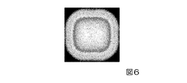
本発明者は、本実施形態の第2光源装置102について、拡散素子22から所定距離離れた位置での青色光束BHの照度分布のシミュレーションを行った。
図6は、拡散素子22から射出された青色光束BHの照度分布を示すシミュレーション結果である。図6において、白っぽく見える領域は照度が相対的に高い領域であり、黒っぽく見える領域は照度が相対的に低い領域である。
図6に示すように、光軸ax4に近い中央部の照度が角部の照度に比べて高くなっており、第1比較例の光源装置による領域中央部の照度低下の問題は改善されることが判った。さらに、同じ照度を占める領域の形状が概ね矩形状であり、拡散素子22の後段に位置する第2インテグレーター光学系27の外形も矩形状であるため、拡散素子22から射出された青色光束BHを第2インテグレーター光学系27に効率良く入射させることができる。
The present inventor has simulated the illuminance distribution of the blue luminous flux BH at a position separated from the
FIG. 6 is a simulation result showing the illuminance distribution of the blue luminous flux BH emitted from the diffusing
As shown in FIG. 6, the illuminance in the central portion near the optical axis ax4 is higher than the illuminance in the corner portion, and the problem of illuminance reduction in the central portion of the region due to the light source device of the first comparative example is improved. I found out. Further, since the shape of the region occupying the same illuminance is generally rectangular and the outer shape of the second integrator
以上説明したように、本実施形態によれば、被照明領域の中央部での照度低下のおそれが少なく、照度分布が略均一であり、かつ、小型の第2光源装置102を提供することができる。
As described above, according to the present embodiment, it is possible to provide the second
また、本実施形態の第2光源装置102の採用により、投射画像の明るさムラおよび色ムラが少なく、小型のプロジェクター1を提供することができる。特に本実施形態の場合、拡散素子22から射出された青色光束BHの光路を凹面ミラー30によって折り返しているため、拡散素子22よりも後段の物理的距離を短くでき、プロジェクター1の小型化に寄与することができる。
Further, by adopting the second
[変形例]
上記実施形態では、拡散素子22上の複数の光源像S1,S2,S3,S4の配置が図5のようになっている場合を挙げたが、拡散素子22上の複数の光源像S1,S2,S3,S4は、必ずしも図5のように配置されていなくてもよい。
[Modification example]
In the above embodiment, the case where the plurality of light source images S1, S2, S3, and S4 on the
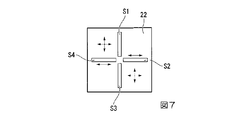
図7は、本変形例の第2光源装置による拡散素子上の複数の光源像の配置を示す図である。
図7に示すように、本変形例の第2光源装置において、第1光源像S1の長手方向および第3光源像S3の長手方向は、拡散素子22上の第1方向に沿い、第2光源像S2の長手方向および第4光源像S4の長手方向は、拡散素子22上の第1方向に直交する第2方向に沿っている。この特徴点については、上記実施形態と同様である。
FIG. 7 is a diagram showing the arrangement of a plurality of light source images on the diffuser element by the second light source device of this modification.
As shown in FIG. 7, in the second light source device of the present modification, the longitudinal direction of the first light source image S1 and the longitudinal direction of the third light source image S3 are along the first direction on the
ただし、上記実施形態とは異なる特徴点として、第1光源像S1、第2光源像S2、第3光源像S3、および第4光源像S4は、拡散素子22上において、全ての光源像S1,S2,S3,S4の短辺が拡散素子22の中心に対向するように、配置されている。
However, as a feature different from the above embodiment, the first light source image S1, the second light source image S2, the third light source image S3, and the fourth light source image S4 are all the light source images S1 on the
本変形例の場合も、上記実施形態と同様、第1光源31と拡散素子22との間の第1の光L1の光路上および第3光源33と拡散素子22との間の第3の光L3の光路上、または第2光源32と拡散素子22との間の第2の光L2の光路上および第4光源34と拡散素子22との間の第4の光L4の光路上に位相差板が設けられていれば、偏光方向が互いに揃った光を含む青色光束BHを拡散素子22から射出させることができる。光源装置の図示を省略するが、本変形例の場合も、各光路変更素子の前段ミラーが拡散素子22の外側の位置に配置されるため、各光路変更素子の前段ミラー同士が干渉するおそれを少なくできる。
In the case of this modification as well, as in the above embodiment, the third light on the optical path of the first light L1 between the
本発明者は、本変形例の光源装置について、拡散素子22から所定距離離れた位置での青色光束BHの照度分布のシミュレーションを行った。
図8は、拡散素子22から射出された青色光束BHの照度分布を示すシミュレーション結果である。図8において、白っぽく見える領域は照度が相対的に高い領域であり、黒っぽく見える領域は照度が相対的に低い領域である。
図8に示すように、光軸に近い中央部の照度が角部の照度に比べて高くなっており、第1比較例の光源装置による中央部の照度低下の問題は改善されることが判った。
The present inventor simulated the illuminance distribution of the blue luminous flux BH at a position separated from the diffusing
FIG. 8 is a simulation result showing the illuminance distribution of the blue luminous flux BH emitted from the diffusing
As shown in FIG. 8, the illuminance in the central portion near the optical axis is higher than the illuminance in the corner portion, and it is found that the problem of the illuminance decrease in the central portion due to the light source device of the first comparative example is improved. It was.
[第2実施形態]
以下、本願の第2実施形態について、図13を用いて説明する。
第2実施形態のプロジェクターおよび光源装置の構成は第1実施形態と略同様である。そのため、プロジェクターおよび光源装置の詳細な説明は省略し、異なる部分のみを説明する。
図13は、第2実施形態の第2光源装置の概略構成図である。
図13において、第1実施形態で用いた図面と共通の構成要素には同一の符号を付し、説明を省略する。
[Second Embodiment]
Hereinafter, the second embodiment of the present application will be described with reference to FIG.
The configuration of the projector and the light source device of the second embodiment is substantially the same as that of the first embodiment. Therefore, detailed description of the projector and the light source device will be omitted, and only different parts will be described.
FIG. 13 is a schematic configuration diagram of the second light source device of the second embodiment.
In FIG. 13, components common to the drawings used in the first embodiment are designated by the same reference numerals, and description thereof will be omitted.
図13に示すように、本実施形態の第2光源装置104は、光源部21と、拡散素子22と、距離短縮部23と、第1位相差板(図示略)と、第2位相差板25と、第2コリメーター光学系26と、第2インテグレーター光学系27と、集光レンズ46と、ミラー47と、を備えている。光源部21、拡散素子22、距離短縮部23、第1位相差板、第2位相差板25、第2コリメーター光学系26、および第2インテグレーター光学系27の構成は、第1実施形態と同様である。
As shown in FIG. 13, the second
集光レンズ46は、凸レンズから構成されている。ミラー47は、光軸ax4と45°の角度をなすように配置されている。本実施形態においては、第2インテグレーター光学系27から射出された青色光束BHは、集光レンズ46によって集束され、ミラー47によって反射されて、光変調素子400Bに導かれる。
The
本実施形態においても、被照明領域の中央部での照度低下のおそれが少なく、小型の光源装置を提供できる、投射画像の明るさムラおよび色ムラが少なく、小型のプロジェクターを提供できる、といった第1実施形態と同様の効果が得られる。 Also in the present embodiment, there is little risk of illuminance decrease in the central portion of the illuminated area, a small light source device can be provided, brightness unevenness and color unevenness of the projected image are small, and a small projector can be provided. 1 The same effect as that of the embodiment can be obtained.
なお、本願の技術範囲は上記実施形態に限定されるものではなく、本願の趣旨を逸脱しない範囲において種々の変更を加えることが可能である。
例えば上記実施形態では、第1光源装置として、固定型の波長変換素子を備えた光源装置の例を挙げたが、この構成に代えて、モーター等の駆動源によって回転可能とされた波長変換素子を備える光源装置が用いられてもよい。同様に、上記実施形態では、第2光源装置として、固定型の拡散素子を備えた光源装置の例を挙げたが、この構成に代えて、モーター等の駆動源によって回転可能とされた拡散素子を備える光源装置が用いられてもよい。
The technical scope of the present application is not limited to the above-described embodiment, and various changes can be made without departing from the spirit of the present application.
For example, in the above embodiment, an example of a light source device provided with a fixed wavelength conversion element is given as the first light source device, but instead of this configuration, a wavelength conversion element made rotatable by a drive source such as a motor. A light source device comprising the above may be used. Similarly, in the above embodiment, an example of a light source device provided with a fixed diffusion element is given as the second light source device, but instead of this configuration, a diffusion element made rotatable by a drive source such as a motor or the like is given. A light source device comprising the above may be used.
その他、プロジェクターの各構成要素の形状、数、配置、材料等の具体的な記載については、上記実施形態に限らず、適宜変更が可能である。また、上記実施形態では、本願を、液晶ライトバルブを用いたプロジェクターに適用した例を示したが、これに限られない。本願を、光変調装置としてデジタルマイクロミラーデバイスを用いたプロジェクターに適用してもよい。 In addition, the specific description of the shape, number, arrangement, material, and the like of each component of the projector is not limited to the above embodiment, and can be changed as appropriate. Further, in the above embodiment, an example in which the present application is applied to a projector using a liquid crystal light bulb is shown, but the present invention is not limited to this. The present application may be applied to a projector using a digital micromirror device as an optical modulation device.
1…プロジェクター、21…光源部、22…拡散素子、23…距離短縮部、24…第1位相差板、25…第2位相差板、31…第1光源、32…第2光源、33…第3光源、34…第4光源、35…第2発光素子(レーザー素子)、36…結像レンズ、41…第1光路変更素子、42…第2光路変更素子、43…第3光路変更素子、44…第4光路変更素子、102,104…第2光源装置(光源装置)、400…光変調装置、411…第1前段ミラー、412…第1後段ミラー、421…第2前段ミラー、422…第2後段ミラー、431…第3前段ミラー、432…第3後段ミラー、441…第4前段ミラー、442…第4後段ミラー、600…投射光学装置、BH…青色光束(光束)、L1…第1の光、L2…第2の光、L3…第3の光、L4…第4の光。 1 ... Projector, 21 ... Light source unit, 22 ... Diffusing element, 23 ... Distance shortening unit, 24 ... First phase difference plate, 25 ... Second phase difference plate, 31 ... First light source, 32 ... Second light source, 33 ... 3rd light source, 34 ... 4th light source, 35 ... 2nd light emitting element (laser element), 36 ... imaging lens, 41 ... 1st optical path changing element, 42 ... 2nd optical path changing element, 43 ... 3rd optical path changing element , 44 ... 4th optical path changing element, 102, 104 ... 2nd light source device (light source device), 400 ... Optical modulator, 411 ... 1st front mirror, 412 ... 1st rear mirror, 421 ... 2nd front mirror, 422 ... 2nd rear stage mirror, 431 ... 3rd front stage mirror, 432 ... 3rd rear stage mirror, 441 ... 4th front stage mirror, 442 ... 4th rear stage mirror, 600 ... Projection optical device, BH ... Blue light source (light source), L1 ... First light, L2 ... second light, L3 ... third light, L4 ... fourth light.
Claims (5)
第2の光を射出する第2光源と、
第3の光を射出する第3光源と、
第4の光を射出する第4光源と、
前記第1の光、前記第2の光、前記第3の光、および前記第4の光を拡散させる拡散素子と、
前記第1光源と前記拡散素子との間の前記第1の光の光路上に設けられ、前記第1の光の光路を折り返す第1光路変更素子と、
前記第2光源と前記拡散素子との間の前記第2の光の光路上に設けられ、前記第2の光の光路を折り返す第2光路変更素子と、
前記第3光源と前記拡散素子との間の前記第3の光の光路上に設けられ、前記第3の光の光路を折り返す第3光路変更素子と、
前記第4光源と前記拡散素子との間の前記第4の光の光路上に設けられ、前記第4の光の光路を折り返す第4光路変更素子と、
を備え、
前記第1光源は、第1光源像を前記拡散素子上の第1位置に形成し、
前記第2光源は、第2光源像を前記拡散素子上の前記第1位置とは異なる第2位置に形成し、
前記第3光源は、第3光源像を前記拡散素子上の前記第1位置および前記第2位置とは異なる第3位置に形成し、
前記第4光源は、第4光源像を前記拡散素子上の前記第1位置、前記第2位置および前記第3位置とは異なる第4位置に形成し、
前記第1光源像の長手方向および前記第3光源像の長手方向は、前記拡散素子上の第1方向に沿い、
前記第2光源像の長手方向および前記第4光源像の長手方向は、前記拡散素子上の前記第1方向に直交する第2方向に沿い、
前記第1の光の光路上に第1位相差板が設けられ、前記第3の光の光路上に第2位相差板が設けられている、光源装置。 The first light source that emits the first light and
A second light source that emits a second light,
A third light source that emits a third light,
A fourth light source that emits a fourth light,
A diffusing element that diffuses the first light, the second light, the third light, and the fourth light.
A first optical path changing element provided on the optical path of the first light between the first light source and the diffusing element and folding back the optical path of the first light.
A second optical path changing element provided on the optical path of the second light between the second light source and the diffusing element and folding back the optical path of the second light.
A third optical path changing element provided on the optical path of the third light between the third light source and the diffusing element and folding back the optical path of the third light.
A fourth optical path changing element provided on the optical path of the fourth light between the fourth light source and the diffusing element and folding back the optical path of the fourth light.
With
The first light source forms a first light source image at a first position on the diffusion element.
The second light source forms the second light source image at a second position different from the first position on the diffusion element.
The third light source forms a third light source image at a third position different from the first position and the second position on the diffusion element.
The fourth light source forms a fourth light source image at a fourth position different from the first position, the second position, and the third position on the diffusion element.
The longitudinal direction of the first light source image and the longitudinal direction of the third light source image are along the first direction on the diffusion element.
The longitudinal direction of the second light source image and the longitudinal direction of the fourth light source image are along a second direction orthogonal to the first direction on the diffusion element.
A light source device in which a first retardation plate is provided on the optical path of the first light, and a second retardation plate is provided on the optical path of the third light.
前記第2光路変更素子は、前記第2光源から射出された前記第2の光を反射させる第2前段ミラーと、前記第2前段ミラーで反射した前記第2の光を反射させる第2後段ミラーと、を有し、
前記第3光路変更素子は、前記第3光源から射出された前記第3の光を反射させる第3前段ミラーと、前記第3前段ミラーで反射した前記第3の光を反射させる第3後段ミラーと、を有し、
前記第4光路変更素子は、前記第4光源から射出された前記第4の光を反射させる第4前段ミラーと、前記第4前段ミラーで反射した前記第4の光を反射させる第4後段ミラーと、を有する、請求項1に記載の光源装置。 The first optical path changing element includes a first front-stage mirror that reflects the first light emitted from the first light source and a first rear-stage mirror that reflects the first light reflected by the first front-stage mirror. And have
The second optical path changing element includes a second front-stage mirror that reflects the second light emitted from the second light source and a second rear-stage mirror that reflects the second light reflected by the second front-stage mirror. And have
The third optical path changing element includes a third front-stage mirror that reflects the third light emitted from the third light source, and a third rear-stage mirror that reflects the third light reflected by the third front-stage mirror. And have
The fourth optical path changing element includes a fourth front-stage mirror that reflects the fourth light emitted from the fourth light source and a fourth rear-stage mirror that reflects the fourth light reflected by the fourth front-stage mirror. The light source device according to claim 1, further comprising.
前記第2位相差板は、前記第3の光の波長帯に対する1/2波長板で構成されている、請求項1から請求項3までのいずれか一項に記載の光源装置。 The first phase difference plate is composed of a 1/2 wave plate with respect to the wavelength band of the first light.
The light source device according to any one of claims 1 to 3, wherein the second retardation plate is composed of a 1/2 wave plate for the wavelength band of the third light.
前記光源装置からの光を画像情報に応じて変調する光変調装置と、
前記光変調装置により変調された光を投射する投射光学装置と、
を備える、プロジェクター。 The light source device according to any one of claims 1 to 4.
An optical modulation device that modulates the light from the light source device according to image information,
A projection optical device that projects light modulated by the light modulation device, and
Equipped with a projector.
Priority Applications (1)
| Application Number | Priority Date | Filing Date | Title |
|---|---|---|---|
| JP2019215069A JP2021086009A (en) | 2019-11-28 | 2019-11-28 | Light source device and projector |
Applications Claiming Priority (1)
| Application Number | Priority Date | Filing Date | Title |
|---|---|---|---|
| JP2019215069A JP2021086009A (en) | 2019-11-28 | 2019-11-28 | Light source device and projector |
Publications (1)
| Publication Number | Publication Date |
|---|---|
| JP2021086009A true JP2021086009A (en) | 2021-06-03 |
Family
ID=76087546
Family Applications (1)
| Application Number | Title | Priority Date | Filing Date |
|---|---|---|---|
| JP2019215069A Pending JP2021086009A (en) | 2019-11-28 | 2019-11-28 | Light source device and projector |
Country Status (1)
| Country | Link |
|---|---|
| JP (1) | JP2021086009A (en) |
-
2019
- 2019-11-28 JP JP2019215069A patent/JP2021086009A/en active Pending
Similar Documents
| Publication | Publication Date | Title |
|---|---|---|
| JP6828268B2 (en) | Light source device and projector | |
| JP7039909B2 (en) | Lighting equipment and projectors | |
| JP6866682B2 (en) | Lighting equipment and projector | |
| JP2007294337A (en) | Lighting system and projector | |
| CN108227358B (en) | Illumination device and projector | |
| US10564531B2 (en) | Light source device and projector | |
| JP6766617B2 (en) | Light source device and projector | |
| US11327392B2 (en) | Light source device and projector in which wave plates are downsized | |
| JP2017083636A (en) | Illumination device and projector | |
| JP2015049441A (en) | Illumination device and projector | |
| JP7009910B2 (en) | Light source device and projector | |
| JP6790546B2 (en) | Wavelength converters, light source devices and projectors | |
| JP6269037B2 (en) | Fluorescent light emitting device, light source device and projector | |
| US20170242266A1 (en) | Illumination device and projector | |
| JP2016145881A (en) | Wavelength conversion element, illumination device, and projector | |
| US11474424B2 (en) | Light source device and projector | |
| JP2019008018A (en) | Illumination device and projector | |
| JP2019028085A (en) | Light source device, illumination device, and projector | |
| JP2021189390A (en) | Illumination device and projector | |
| JP2021086009A (en) | Light source device and projector | |
| JP2021076738A (en) | projector | |
| JP2007140432A (en) | Illumination device and projector | |
| JP2007233121A (en) | Illuminating apparatus and projector | |
| JP2005284307A (en) | Image display device | |
| JP7257599B2 (en) | Light source device and projection type image display device |
Legal Events
| Date | Code | Title | Description |
|---|---|---|---|
| RD07 | Notification of extinguishment of power of attorney |
Free format text: JAPANESE INTERMEDIATE CODE: A7427 Effective date: 20200811 |
|
| RD04 | Notification of resignation of power of attorney |
Free format text: JAPANESE INTERMEDIATE CODE: A7424 Effective date: 20210915 |
|
| RD03 | Notification of appointment of power of attorney |
Free format text: JAPANESE INTERMEDIATE CODE: A7423 Effective date: 20211101 |