JP2021082425A - Method and system for charging battery - Google Patents
Method and system for charging battery Download PDFInfo
- Publication number
- JP2021082425A JP2021082425A JP2019207256A JP2019207256A JP2021082425A JP 2021082425 A JP2021082425 A JP 2021082425A JP 2019207256 A JP2019207256 A JP 2019207256A JP 2019207256 A JP2019207256 A JP 2019207256A JP 2021082425 A JP2021082425 A JP 2021082425A
- Authority
- JP
- Japan
- Prior art keywords
- battery
- charging
- soc
- charging current
- entropy
- Prior art date
- Legal status (The legal status is an assumption and is not a legal conclusion. Google has not performed a legal analysis and makes no representation as to the accuracy of the status listed.)
- Granted
Links
Images


Classifications
-
- H—ELECTRICITY
- H01—ELECTRIC ELEMENTS
- H01M—PROCESSES OR MEANS, e.g. BATTERIES, FOR THE DIRECT CONVERSION OF CHEMICAL ENERGY INTO ELECTRICAL ENERGY
- H01M10/00—Secondary cells; Manufacture thereof
- H01M10/42—Methods or arrangements for servicing or maintenance of secondary cells or secondary half-cells
- H01M10/44—Methods for charging or discharging
-
- B—PERFORMING OPERATIONS; TRANSPORTING
- B60—VEHICLES IN GENERAL
- B60L—PROPULSION OF ELECTRICALLY-PROPELLED VEHICLES; SUPPLYING ELECTRIC POWER FOR AUXILIARY EQUIPMENT OF ELECTRICALLY-PROPELLED VEHICLES; ELECTRODYNAMIC BRAKE SYSTEMS FOR VEHICLES IN GENERAL; MAGNETIC SUSPENSION OR LEVITATION FOR VEHICLES; MONITORING OPERATING VARIABLES OF ELECTRICALLY-PROPELLED VEHICLES; ELECTRIC SAFETY DEVICES FOR ELECTRICALLY-PROPELLED VEHICLES
- B60L53/00—Methods of charging batteries, specially adapted for electric vehicles; Charging stations or on-board charging equipment therefor; Exchange of energy storage elements in electric vehicles
- B60L53/60—Monitoring or controlling charging stations
- B60L53/62—Monitoring or controlling charging stations in response to charging parameters, e.g. current, voltage or electrical charge
-
- B—PERFORMING OPERATIONS; TRANSPORTING
- B60—VEHICLES IN GENERAL
- B60L—PROPULSION OF ELECTRICALLY-PROPELLED VEHICLES; SUPPLYING ELECTRIC POWER FOR AUXILIARY EQUIPMENT OF ELECTRICALLY-PROPELLED VEHICLES; ELECTRODYNAMIC BRAKE SYSTEMS FOR VEHICLES IN GENERAL; MAGNETIC SUSPENSION OR LEVITATION FOR VEHICLES; MONITORING OPERATING VARIABLES OF ELECTRICALLY-PROPELLED VEHICLES; ELECTRIC SAFETY DEVICES FOR ELECTRICALLY-PROPELLED VEHICLES
- B60L53/00—Methods of charging batteries, specially adapted for electric vehicles; Charging stations or on-board charging equipment therefor; Exchange of energy storage elements in electric vehicles
- B60L53/60—Monitoring or controlling charging stations
- B60L53/66—Data transfer between charging stations and vehicles
-
- B—PERFORMING OPERATIONS; TRANSPORTING
- B60—VEHICLES IN GENERAL
- B60L—PROPULSION OF ELECTRICALLY-PROPELLED VEHICLES; SUPPLYING ELECTRIC POWER FOR AUXILIARY EQUIPMENT OF ELECTRICALLY-PROPELLED VEHICLES; ELECTRODYNAMIC BRAKE SYSTEMS FOR VEHICLES IN GENERAL; MAGNETIC SUSPENSION OR LEVITATION FOR VEHICLES; MONITORING OPERATING VARIABLES OF ELECTRICALLY-PROPELLED VEHICLES; ELECTRIC SAFETY DEVICES FOR ELECTRICALLY-PROPELLED VEHICLES
- B60L58/00—Methods or circuit arrangements for monitoring or controlling batteries or fuel cells, specially adapted for electric vehicles
- B60L58/10—Methods or circuit arrangements for monitoring or controlling batteries or fuel cells, specially adapted for electric vehicles for monitoring or controlling batteries
- B60L58/12—Methods or circuit arrangements for monitoring or controlling batteries or fuel cells, specially adapted for electric vehicles for monitoring or controlling batteries responding to state of charge [SoC]
-
- H—ELECTRICITY
- H01—ELECTRIC ELEMENTS
- H01M—PROCESSES OR MEANS, e.g. BATTERIES, FOR THE DIRECT CONVERSION OF CHEMICAL ENERGY INTO ELECTRICAL ENERGY
- H01M10/00—Secondary cells; Manufacture thereof
- H01M10/42—Methods or arrangements for servicing or maintenance of secondary cells or secondary half-cells
- H01M10/48—Accumulators combined with arrangements for measuring, testing or indicating the condition of cells, e.g. the level or density of the electrolyte
-
- H—ELECTRICITY
- H02—GENERATION; CONVERSION OR DISTRIBUTION OF ELECTRIC POWER
- H02J—CIRCUIT ARRANGEMENTS OR SYSTEMS FOR SUPPLYING OR DISTRIBUTING ELECTRIC POWER; SYSTEMS FOR STORING ELECTRIC ENERGY
- H02J7/00—Circuit arrangements for charging or depolarising batteries or for supplying loads from batteries
- H02J7/0047—Circuit arrangements for charging or depolarising batteries or for supplying loads from batteries with monitoring or indicating devices or circuits
- H02J7/0048—Detection of remaining charge capacity or state of charge [SOC]
-
- H—ELECTRICITY
- H02—GENERATION; CONVERSION OR DISTRIBUTION OF ELECTRIC POWER
- H02J—CIRCUIT ARRANGEMENTS OR SYSTEMS FOR SUPPLYING OR DISTRIBUTING ELECTRIC POWER; SYSTEMS FOR STORING ELECTRIC ENERGY
- H02J7/00—Circuit arrangements for charging or depolarising batteries or for supplying loads from batteries
- H02J7/007—Regulation of charging or discharging current or voltage
- H02J7/00712—Regulation of charging or discharging current or voltage the cycle being controlled or terminated in response to electric parameters
- H02J7/00714—Regulation of charging or discharging current or voltage the cycle being controlled or terminated in response to electric parameters in response to battery charging or discharging current
-
- H—ELECTRICITY
- H02—GENERATION; CONVERSION OR DISTRIBUTION OF ELECTRIC POWER
- H02J—CIRCUIT ARRANGEMENTS OR SYSTEMS FOR SUPPLYING OR DISTRIBUTING ELECTRIC POWER; SYSTEMS FOR STORING ELECTRIC ENERGY
- H02J7/00—Circuit arrangements for charging or depolarising batteries or for supplying loads from batteries
- H02J7/007—Regulation of charging or discharging current or voltage
- H02J7/007188—Regulation of charging or discharging current or voltage the charge cycle being controlled or terminated in response to non-electric parameters
- H02J7/007192—Regulation of charging or discharging current or voltage the charge cycle being controlled or terminated in response to non-electric parameters in response to temperature
-
- H—ELECTRICITY
- H02—GENERATION; CONVERSION OR DISTRIBUTION OF ELECTRIC POWER
- H02J—CIRCUIT ARRANGEMENTS OR SYSTEMS FOR SUPPLYING OR DISTRIBUTING ELECTRIC POWER; SYSTEMS FOR STORING ELECTRIC ENERGY
- H02J7/00—Circuit arrangements for charging or depolarising batteries or for supplying loads from batteries
- H02J7/14—Circuit arrangements for charging or depolarising batteries or for supplying loads from batteries for charging batteries from dynamo-electric generators driven at varying speed, e.g. on vehicle
- H02J7/1469—Regulation of the charging current or voltage otherwise than by variation of field
- H02J7/1492—Regulation of the charging current or voltage otherwise than by variation of field by means of controlling devices between the generator output and the battery
-
- B—PERFORMING OPERATIONS; TRANSPORTING
- B60—VEHICLES IN GENERAL
- B60L—PROPULSION OF ELECTRICALLY-PROPELLED VEHICLES; SUPPLYING ELECTRIC POWER FOR AUXILIARY EQUIPMENT OF ELECTRICALLY-PROPELLED VEHICLES; ELECTRODYNAMIC BRAKE SYSTEMS FOR VEHICLES IN GENERAL; MAGNETIC SUSPENSION OR LEVITATION FOR VEHICLES; MONITORING OPERATING VARIABLES OF ELECTRICALLY-PROPELLED VEHICLES; ELECTRIC SAFETY DEVICES FOR ELECTRICALLY-PROPELLED VEHICLES
- B60L2240/00—Control parameters of input or output; Target parameters
- B60L2240/40—Drive Train control parameters
- B60L2240/54—Drive Train control parameters related to batteries
- B60L2240/547—Voltage
-
- B—PERFORMING OPERATIONS; TRANSPORTING
- B60—VEHICLES IN GENERAL
- B60L—PROPULSION OF ELECTRICALLY-PROPELLED VEHICLES; SUPPLYING ELECTRIC POWER FOR AUXILIARY EQUIPMENT OF ELECTRICALLY-PROPELLED VEHICLES; ELECTRODYNAMIC BRAKE SYSTEMS FOR VEHICLES IN GENERAL; MAGNETIC SUSPENSION OR LEVITATION FOR VEHICLES; MONITORING OPERATING VARIABLES OF ELECTRICALLY-PROPELLED VEHICLES; ELECTRIC SAFETY DEVICES FOR ELECTRICALLY-PROPELLED VEHICLES
- B60L2240/00—Control parameters of input or output; Target parameters
- B60L2240/40—Drive Train control parameters
- B60L2240/54—Drive Train control parameters related to batteries
- B60L2240/549—Current
-
- H—ELECTRICITY
- H01—ELECTRIC ELEMENTS
- H01M—PROCESSES OR MEANS, e.g. BATTERIES, FOR THE DIRECT CONVERSION OF CHEMICAL ENERGY INTO ELECTRICAL ENERGY
- H01M2220/00—Batteries for particular applications
- H01M2220/20—Batteries in motive systems, e.g. vehicle, ship, plane
-
- H—ELECTRICITY
- H02—GENERATION; CONVERSION OR DISTRIBUTION OF ELECTRIC POWER
- H02J—CIRCUIT ARRANGEMENTS OR SYSTEMS FOR SUPPLYING OR DISTRIBUTING ELECTRIC POWER; SYSTEMS FOR STORING ELECTRIC ENERGY
- H02J2310/00—The network for supplying or distributing electric power characterised by its spatial reach or by the load
- H02J2310/40—The network being an on-board power network, i.e. within a vehicle
- H02J2310/48—The network being an on-board power network, i.e. within a vehicle for electric vehicles [EV] or hybrid vehicles [HEV]
-
- H—ELECTRICITY
- H02—GENERATION; CONVERSION OR DISTRIBUTION OF ELECTRIC POWER
- H02J—CIRCUIT ARRANGEMENTS OR SYSTEMS FOR SUPPLYING OR DISTRIBUTING ELECTRIC POWER; SYSTEMS FOR STORING ELECTRIC ENERGY
- H02J7/00—Circuit arrangements for charging or depolarising batteries or for supplying loads from batteries
- H02J7/02—Circuit arrangements for charging or depolarising batteries or for supplying loads from batteries for charging batteries from ac mains by converters
- H02J7/04—Regulation of charging current or voltage
-
- Y—GENERAL TAGGING OF NEW TECHNOLOGICAL DEVELOPMENTS; GENERAL TAGGING OF CROSS-SECTIONAL TECHNOLOGIES SPANNING OVER SEVERAL SECTIONS OF THE IPC; TECHNICAL SUBJECTS COVERED BY FORMER USPC CROSS-REFERENCE ART COLLECTIONS [XRACs] AND DIGESTS
- Y02—TECHNOLOGIES OR APPLICATIONS FOR MITIGATION OR ADAPTATION AGAINST CLIMATE CHANGE
- Y02E—REDUCTION OF GREENHOUSE GAS [GHG] EMISSIONS, RELATED TO ENERGY GENERATION, TRANSMISSION OR DISTRIBUTION
- Y02E60/00—Enabling technologies; Technologies with a potential or indirect contribution to GHG emissions mitigation
- Y02E60/10—Energy storage using batteries
-
- Y—GENERAL TAGGING OF NEW TECHNOLOGICAL DEVELOPMENTS; GENERAL TAGGING OF CROSS-SECTIONAL TECHNOLOGIES SPANNING OVER SEVERAL SECTIONS OF THE IPC; TECHNICAL SUBJECTS COVERED BY FORMER USPC CROSS-REFERENCE ART COLLECTIONS [XRACs] AND DIGESTS
- Y02—TECHNOLOGIES OR APPLICATIONS FOR MITIGATION OR ADAPTATION AGAINST CLIMATE CHANGE
- Y02T—CLIMATE CHANGE MITIGATION TECHNOLOGIES RELATED TO TRANSPORTATION
- Y02T10/00—Road transport of goods or passengers
- Y02T10/60—Other road transportation technologies with climate change mitigation effect
- Y02T10/70—Energy storage systems for electromobility, e.g. batteries
-
- Y—GENERAL TAGGING OF NEW TECHNOLOGICAL DEVELOPMENTS; GENERAL TAGGING OF CROSS-SECTIONAL TECHNOLOGIES SPANNING OVER SEVERAL SECTIONS OF THE IPC; TECHNICAL SUBJECTS COVERED BY FORMER USPC CROSS-REFERENCE ART COLLECTIONS [XRACs] AND DIGESTS
- Y02—TECHNOLOGIES OR APPLICATIONS FOR MITIGATION OR ADAPTATION AGAINST CLIMATE CHANGE
- Y02T—CLIMATE CHANGE MITIGATION TECHNOLOGIES RELATED TO TRANSPORTATION
- Y02T10/00—Road transport of goods or passengers
- Y02T10/60—Other road transportation technologies with climate change mitigation effect
- Y02T10/7072—Electromobility specific charging systems or methods for batteries, ultracapacitors, supercapacitors or double-layer capacitors
-
- Y—GENERAL TAGGING OF NEW TECHNOLOGICAL DEVELOPMENTS; GENERAL TAGGING OF CROSS-SECTIONAL TECHNOLOGIES SPANNING OVER SEVERAL SECTIONS OF THE IPC; TECHNICAL SUBJECTS COVERED BY FORMER USPC CROSS-REFERENCE ART COLLECTIONS [XRACs] AND DIGESTS
- Y02—TECHNOLOGIES OR APPLICATIONS FOR MITIGATION OR ADAPTATION AGAINST CLIMATE CHANGE
- Y02T—CLIMATE CHANGE MITIGATION TECHNOLOGIES RELATED TO TRANSPORTATION
- Y02T10/00—Road transport of goods or passengers
- Y02T10/80—Technologies aiming to reduce greenhouse gasses emissions common to all road transportation technologies
- Y02T10/92—Energy efficient charging or discharging systems for batteries, ultracapacitors, supercapacitors or double-layer capacitors specially adapted for vehicles
-
- Y—GENERAL TAGGING OF NEW TECHNOLOGICAL DEVELOPMENTS; GENERAL TAGGING OF CROSS-SECTIONAL TECHNOLOGIES SPANNING OVER SEVERAL SECTIONS OF THE IPC; TECHNICAL SUBJECTS COVERED BY FORMER USPC CROSS-REFERENCE ART COLLECTIONS [XRACs] AND DIGESTS
- Y02—TECHNOLOGIES OR APPLICATIONS FOR MITIGATION OR ADAPTATION AGAINST CLIMATE CHANGE
- Y02T—CLIMATE CHANGE MITIGATION TECHNOLOGIES RELATED TO TRANSPORTATION
- Y02T90/00—Enabling technologies or technologies with a potential or indirect contribution to GHG emissions mitigation
- Y02T90/10—Technologies relating to charging of electric vehicles
- Y02T90/12—Electric charging stations
-
- Y—GENERAL TAGGING OF NEW TECHNOLOGICAL DEVELOPMENTS; GENERAL TAGGING OF CROSS-SECTIONAL TECHNOLOGIES SPANNING OVER SEVERAL SECTIONS OF THE IPC; TECHNICAL SUBJECTS COVERED BY FORMER USPC CROSS-REFERENCE ART COLLECTIONS [XRACs] AND DIGESTS
- Y02—TECHNOLOGIES OR APPLICATIONS FOR MITIGATION OR ADAPTATION AGAINST CLIMATE CHANGE
- Y02T—CLIMATE CHANGE MITIGATION TECHNOLOGIES RELATED TO TRANSPORTATION
- Y02T90/00—Enabling technologies or technologies with a potential or indirect contribution to GHG emissions mitigation
- Y02T90/10—Technologies relating to charging of electric vehicles
- Y02T90/14—Plug-in electric vehicles
-
- Y—GENERAL TAGGING OF NEW TECHNOLOGICAL DEVELOPMENTS; GENERAL TAGGING OF CROSS-SECTIONAL TECHNOLOGIES SPANNING OVER SEVERAL SECTIONS OF THE IPC; TECHNICAL SUBJECTS COVERED BY FORMER USPC CROSS-REFERENCE ART COLLECTIONS [XRACs] AND DIGESTS
- Y02—TECHNOLOGIES OR APPLICATIONS FOR MITIGATION OR ADAPTATION AGAINST CLIMATE CHANGE
- Y02T—CLIMATE CHANGE MITIGATION TECHNOLOGIES RELATED TO TRANSPORTATION
- Y02T90/00—Enabling technologies or technologies with a potential or indirect contribution to GHG emissions mitigation
- Y02T90/10—Technologies relating to charging of electric vehicles
- Y02T90/16—Information or communication technologies improving the operation of electric vehicles
Abstract
Description
本開示は、電池の充電方法および充電システムに関し、より特定的には、非水電解液二次電池の充電電流の制御技術に関する。 The present disclosure relates to a battery charging method and a charging system, and more specifically to a technique for controlling a charging current of a non-aqueous electrolyte secondary battery.
近年、非水電解液二次電池(リチウムイオン二次電池であり、以下、「電池」と略す場合がある)が走行用バッテリとして搭載された車両の普及が進んでいる。その中で、電池容量を増大させることが検討されている。容量を増大させることで、車両のEV走行距離(電池に蓄えられた電力により車両が走行可能な距離)を長くすることができる。その一方で、電池の充電に要する時間も長くなり、ユーザの利便性が低下し得る。そこで、充電時間を短縮すべく、電池を大電流で充電する「急速充電」の開発が進められている。 In recent years, vehicles equipped with a non-aqueous electrolyte secondary battery (a lithium ion secondary battery, which may be abbreviated as "battery" below) as a traveling battery have become widespread. Among them, increasing the battery capacity is being studied. By increasing the capacity, the EV mileage of the vehicle (the distance that the vehicle can travel by the electric power stored in the battery) can be increased. On the other hand, the time required for charging the battery becomes long, which may reduce the convenience of the user. Therefore, in order to shorten the charging time, the development of "quick charging" that charges the battery with a large current is underway.
急速充電時には電池の劣化が特に進行しやすいことが知られている。そのため、急速充電時の電池劣化を抑制するための技術が提案されている。たとえば特開2011−024412号公報(特許文献1)は、サイクル寿命への急速充電の影響を抑制/排除しながら電池の充電時間を短縮する充電システムを開示する。 It is known that the deterioration of the battery is particularly likely to progress during quick charging. Therefore, a technique for suppressing battery deterioration during quick charging has been proposed. For example, Japanese Patent Application Laid-Open No. 2011-024412 (Patent Document 1) discloses a charging system that shortens the charging time of a battery while suppressing / eliminating the influence of rapid charging on the cycle life.
電池の寿命を延ばすため、電池の充電に伴う劣化を抑制する技術に対する要望が常に存在する(たとえば特許文献1参照)。本発明者らは、鋭意検討の結果、電池の充電に伴う劣化を効果的に抑制可能な手法を見出した。 In order to extend the life of the battery, there is always a demand for a technique for suppressing deterioration due to charging of the battery (see, for example, Patent Document 1). As a result of diligent studies, the present inventors have found a method capable of effectively suppressing deterioration associated with battery charging.
本開示は、かかる課題を解決するためになされたものであり、本開示の目的は、非水電解液二次電池の充電に伴う劣化を抑制することである。 The present disclosure has been made to solve such a problem, and an object of the present disclosure is to suppress deterioration due to charging of a non-aqueous electrolyte secondary battery.
(1)本開示のある局面に従う電池の充電方法は、非水電解液二次電池である電池の充電方法である。電池の充電方法は、第1および第2のステップを含む。第1のステップは、電池の電圧および電流のうちの少なくとも一方に基づいて電池のSOCを推定するステップである。第2のステップは、電池のSOCと電池の電池反応のエントロピー変化との間の関係に基づき、電池のエントロピー変化が大きいほど電池への充電電流が大きくなるように、充電電流を電池のSOCに応じて決定するステップである。 (1) A battery charging method according to a certain aspect of the present disclosure is a battery charging method that is a non-aqueous electrolyte secondary battery. The method of charging the battery includes the first step and the second step. The first step is to estimate the SOC of the battery based on at least one of the voltage and current of the battery. The second step is to transfer the charging current to the SOC of the battery so that the larger the entropy change of the battery, the larger the charging current to the battery, based on the relationship between the SOC of the battery and the change in the entropy of the battery reaction of the battery. It is a step to decide accordingly.
(2)決定するステップ(第2のステップ)は、電池のエントロピー変化が正であるSOC領域では、電池のエントロピー変化が負であるSOC領域と比べて、充電電流を大きくするステップを含む。 (2) The step of determining (second step) includes a step of increasing the charging current in the SOC region where the entropy change of the battery is positive as compared with the SOC region where the entropy change of the battery is negative.
(3)電池のエントロピー変化は、第1のSOC領域では負であり、第1のSOC領域よりも高い第2のSOC領域では正であり、第2のSOC領域よりもさらに高い第3のSOC領域では負である。決定するステップ(第2のステップ)は、電池のSOCが第2のSOC領域に含まれる場合には、電池のSOCが第1および第3のSOC領域のうちのいずれかに含まれる場合と比べて、充電電流を大きくするステップを含む。 (3) The change in entropy of the battery is negative in the first SOC region, positive in the second SOC region higher than the first SOC region, and even higher than the second SOC region in the third SOC. Negative in the region. The step to determine (second step) is that when the SOC of the battery is included in the second SOC region, compared to the case where the SOC of the battery is included in any of the first and third SOC regions. The step of increasing the charging current is included.
詳細は後述するが、電池のエントロピー変化が大きく、電池のエントロピー変化が正であるSOC領域では、電池のエントロピー変化が負であるSOC領域と比べて、電池の充電に伴う劣化が進みにくい。そのため、電池のエントロピー変化が正であるSOC領域では、最大充電電流を相対的に大きくしたとしても、電池の劣化(具体的には電池の内部抵抗の上昇)の進行速度を許容範囲内に収めることができる。したがって、上記(1)〜(3)の方法によれば、非水電解液二次電池の充電に伴う劣化を抑制できる。 Although the details will be described later, in the SOC region where the entropy change of the battery is large and the entropy change of the battery is positive, deterioration due to charging of the battery is less likely to proceed than in the SOC region where the entropy change of the battery is negative. Therefore, in the SOC region where the change in the entropy of the battery is positive, the progress rate of battery deterioration (specifically, increase in the internal resistance of the battery) is kept within the allowable range even if the maximum charging current is relatively large. be able to. Therefore, according to the methods (1) to (3) above, deterioration due to charging of the non-aqueous electrolyte secondary battery can be suppressed.
(4)充電電流を大きくするステップは、電池のエントロピー変化が正であるSOC領域では、充電電流のCレートを1.5C以上にし、かつ、電池のエントロピー変化が正であるSOC領域における充電電流を、電池のエントロピー変化が負であるSOC領域における充電電流の1.25倍以上にするステップを含む。 (4) In the step of increasing the charging current, in the SOC region where the entropy change of the battery is positive, the C rate of the charging current is set to 1.5C or more, and the charging current in the SOC region where the entropy change of the battery is positive. Includes a step of 1.25 times or more the charging current in the SOC region where the entropy change of the battery is negative.
上記(4)の方法によれば、本発明者の評価試験の結果(図13参照)に基づき、最大充電電流のCレートの数値範囲を1.5C超か1.5C未満かで規定するとともに、SOC領域間の充電電流の比率の数値範囲を規定する。これにより、非水電解液二次電池の充電に伴う劣化をより好適に抑制できる。 According to the method (4) above, based on the result of the evaluation test of the present inventor (see FIG. 13), the numerical range of the C rate of the maximum charging current is defined as more than 1.5C or less than 1.5C. , Defines the numerical range of the ratio of charging current between SOC regions. As a result, deterioration due to charging of the non-aqueous electrolyte secondary battery can be more preferably suppressed.
(5)本開示の他の局面に従う電池の充電方法は、非水電解液二次電池である電池の充電方法である。電池の充電方法は、第1および第2のステップを含む。第1のステップは、電池の電圧および電流のうちの少なくとも一方に基づいて電池のSOCを推定するステップである。第2のステップは、電池のSOCと電池の電池反応のエントロピー変化との間の関係に基づき、電池への充電電流を電池のSOCに応じて決定するステップである。電池のエントロピー変化が第1の値である場合における電池への充電電流は、電池のエントロピー変化が第1の値よりも小さな第2の値である場合における充電電流よりも大きい。 (5) A battery charging method according to another aspect of the present disclosure is a battery charging method that is a non-aqueous electrolyte secondary battery. The method of charging the battery includes the first step and the second step. The first step is to estimate the SOC of the battery based on at least one of the voltage and current of the battery. The second step is to determine the charging current to the battery according to the SOC of the battery, based on the relationship between the SOC of the battery and the change in entropy of the battery reaction of the battery. The charging current to the battery when the entropy change of the battery is the first value is larger than the charging current when the entropy change of the battery is a second value smaller than the first value.
上記(5)の方法によれば、上記(1)の方法と同様に、非水電解液二次電池の充電に伴う劣化を抑制できる。 According to the method (5) above, deterioration due to charging of the non-aqueous electrolyte secondary battery can be suppressed in the same manner as the method (1) above.
(6)本開示のさらに他の局面に従う充電システムは、非水電解液二次電池である電池と、電池を充電するように構成された充電装置と、電池への充電電流を制御する制御装置とを備える。制御装置は、電池の電圧および電流のうちの少なくとも一方に基づいて電池のSOCを推定する。電池のSOCと電池の電池反応のエントロピー変化との間の関係に基づき、電池のエントロピー変化が大きいほど充電電流が大きくなるように、充電電流を電池のSOCに応じて決定する。 (6) The charging system according to still another aspect of the present disclosure is a battery which is a non-aqueous electrolyte secondary battery, a charging device configured to charge the battery, and a control device for controlling the charging current to the battery. And. The controller estimates the SOC of the battery based on at least one of the voltage and current of the battery. Based on the relationship between the SOC of the battery and the change in the entropy of the battery reaction of the battery, the charging current is determined according to the SOC of the battery so that the larger the change in the entropy of the battery, the larger the charging current.
上記(6)の構成によれば、上記(1)または(5)の方法と同様に、非水電解液二次電池の充電に伴う劣化を抑制できる。 According to the configuration of (6) above, deterioration due to charging of the non-aqueous electrolyte secondary battery can be suppressed as in the method of (1) or (5) above.
本開示によれば、非水電解液二次電池の充電に伴う劣化を抑制できる。 According to the present disclosure, deterioration due to charging of the non-aqueous electrolyte secondary battery can be suppressed.
以下、本開示の実施の形態について図面を参照しながら詳細に説明する。なお、図中同一または相当部分には同一符号を付して、その説明は繰り返さない。 Hereinafter, embodiments of the present disclosure will be described in detail with reference to the drawings. The same or corresponding parts in the drawings are designated by the same reference numerals, and the description thereof will not be repeated.
以下の実施の形態では、本開示に係る充電システムにより、車載の非水電解液二次電池が充電される。ただし、本開示に係る充電システムの用途は、車両用に限定されるものではなく、たとえば定置用であってもよい。 In the following embodiments, the charging system according to the present disclosure charges an in-vehicle non-aqueous electrolyte secondary battery. However, the use of the charging system according to the present disclosure is not limited to that for vehicles, and may be for stationary use, for example.
[実施の形態]
<車両構成>
図1は、本開示の実施の形態に係る充電システムの全体構成を概略的に示す図である。図1を参照して、充電システム1は、車両100と、車両100の外部に設けられた充電設備(充電スタンドなど)900とを備える。
[Embodiment]
<Vehicle configuration>
FIG. 1 is a diagram schematically showing an overall configuration of a charging system according to an embodiment of the present disclosure. With reference to FIG. 1, the charging system 1 includes a
車両100は、代表的にはプラグインハイブリッド車両(PHV:Plug-in Hybrid Vehicle)である。車両100は、充電設備900から充電ケーブル99を介して供給される電力により車載のバッテリ2(図2参照)を充電する「プラグイン充電」が可能に構成されている。しかし、車両100は、プラグインハイブリッド車両に限らず、プラグイン充電が可能な他の種類の電動車両であってもよい。具体的に、車両100は、電気自動車(EV:Electric Vehicle)であってもよいし、プラグイン燃料電池車(PFCV::Plug-in Fuel Cell Vehicle)であってもよい。
The
図2は、本実施の形態に係る車両100および充電設備900の構成を概略的に示す図である。本実施の形態において、充電設備900は、DC(Direct Current)充電が可能な充電器であり、いわゆる「急速充電」に対応している。充電設備900は、電源系統(図示せず)から供給される交流電力を車両100に充電可能な高電圧の直流電力に変換する。充電設備900は、電力線ACLと、AC/DC変換器91と、給電線PL9,NL9と、制御回路92とを備える。
FIG. 2 is a diagram schematically showing the configurations of the
電力線ACLは、電源系統に電気的に接続されている。電力線ACLは、電源系統からの交流電力をAC/DC変換器91へ伝送する。
The power line ACL is electrically connected to the power system. The power line ACL transmits AC power from the power supply system to the AC /
AC/DC変換器91は、電力線ACL上の交流電力を、車両100に搭載されたバッテリ2を充電するための直流電力に変換する。AC/DC変換器91による電力変換は、力率改善のためのAC/DC変換と、電圧レベル調整のためのDC/DC変換との組み合わせによって実行されてもよい。AC/DC変換器91から出力された直流電力は、正極側の給電線PL9と負極側の給電線NL9とに供給される。なお、AC/DC変換器91は、本開示に係る「充電装置」に相当する。
The AC /
制御回路92は、プロセッサと、メモリと、入出力ポート(いずれも図示せず)とを含む。制御回路92は、給電線PL9と給電線NL9との間の電圧、車両100との通信、ならびに、メモリに記憶されたマップおよびプログラムに基づいて、AC/DC変換器91による電力変換動作を制御する。
The
車両100は、インレット11と、充電線PL1,NL1と、電圧センサ12と、電流センサ13と、充電リレー14と、バッテリ2と、監視ユニット3と、システムメインリレー(SMR:System Main Relay)4と、電力制御装置(PCU:Power Control Unit)5と、モータジェネレータ61,62と、エンジン7と、動力分割装置81と、駆動軸82と、駆動輪83と、電子制御装置(ECU:Electronic Control Unit)10とを備える。
The
インレット11は、充電ケーブル99の先端に設けられたコネクタ991が接続されるように構成されている。より詳細には、コネクタ991が嵌合等の機械的な連結を伴ってインレット11に挿入されることにより、充電ケーブル99の給電線PL9とインレット11の正極側の接点との間の電気的な接続が確保されるとともに、給電線NL9とインレット11の負極側の接点との間の電気的な接続が確保される。さらに、充電ケーブル99がインレット11にが接続されることで、車両100のECU10と充電設備900の制御回路92とが各種信号、指令およびデータを相互に送受信することが可能になる。この双方向通信には、CAN(Controller Area Network)等の所定の通信規格に従う通信、または、アナログ制御線を介したアナログ信号による通信を採用できる。
The
充電線PL1,NL1は、インレット11とバッテリ2との間に設けられ、インレット11からの直流電力をバッテリ2に伝送する。
The charging lines PL1 and NL1 are provided between the
電圧センサ12は、インレット11と充電リレー14との間において、充電線PL1と充電線NL1との間に電気的に接続されている。電圧センサ12は、充電線PL1と充電線NL1との間の電圧を検出し、その検出結果をECU10に出力する。電流センサ13は、インレット11と充電リレー14との間において、充電線PL1に電気的に接続されている。電流センサ13は、充電線PL1を流れる電流を検出し、その検出結果をECU10に出力する。ECU10は、電圧センサ12および電流センサ13による検出結果に基づいて、充電設備900から車両100への供給電力(供給電流を含む)を算出できる。
The voltage sensor 12 is electrically connected between the charging line PL1 and the charging line NL1 between the
充電リレー14は,充電線PL1,NL1に電気的に接続されている。充電リレー14は、ECU10からの制御指令に応じて開放/閉成される。充電リレー14が閉成されることで、インレット11からバッテリ2への電力伝送が可能となる。
The charging
バッテリ2は、複数のセル21を含む組電池である。各セル21は、非水電解液二次電池、すなわちリチウムイオン電池である。バッテリ2は、モータジェネレータ61,62を駆動するための電力を蓄え、PCU5を通じてモータジェネレータ61,62へ電力を供給する。さらに、バッテリ2は、車両100のプラグイン充電時に充電設備900からの供給電力により充電される。また、バッテリ2は、モータジェネレータ61,62の発電時にPCU5を通じて発電電力を受けて充電される。
The
監視ユニット3は、電圧センサ31と、電流センサ32と、温度センサ33とを含む。電圧センサ31は、複数のセル21の各々の電圧VBを測定する。電流センサ32は、バッテリ2に入出力される電流IBを測定する。温度センサ33は、複数のセル21からなるブロック(モジュール)毎の温度TBを測定する。各センサは、その測定結果を示す信号をECU10に出力する。ECU10は、電圧センサ31からの信号および/または電流センサ32からの信号に基づいて、バッテリ2の残存容量(SOC:State Of Charge)を推定する。
The
なお、監視ユニット3内の各センサの監視単位は特に限定されない。監視単位は、たとえばセル単位であってもよいし、ブロック単位であってもよい。以下では理解を容易にするため、バッテリ2の内部構成を特に考慮せず、バッテリ2全体を監視単位として説明する。
The monitoring unit of each sensor in the
SMR4は、バッテリ2とPCU5とを結ぶ電力線に電気的に接続されている。SMR4は、ECU10からの制御指令に応じて、バッテリ2とPCU5との間での電力の供給と遮断とを切り替える。
The SMR 4 is electrically connected to a power line connecting the
PCU5は、ECU10からの制御指令に従って、バッテリ2とモータジェネレータ61,62との間で双方向の電力変換を実行する。PCU5は、モータジェネレータ61,62の状態を別々に制御可能に構成されている。PCU5は、たとえば、2つのインバータと、コンバータ(いずれも図示せず)とを含む。2つのインバータは、モータジェネレータ61,62に対応して設けられる。コンバータは、各インバータに供給される直流電圧をバッテリ2の出力電圧以上に昇圧する。
The
モータジェネレータ61,62の各々は、交流回転電機であり、たとえば、ロータに永久磁石(図示せず)が埋設された三相交流同期電動機である。モータジェネレータ61は、主として、動力分割装置81を経由してエンジン7により駆動される発電機として用いられる。モータジェネレータ61が発電した電力は、PCU5を介してモータジェネレータ62またはバッテリ2に供給される。モータジェネレータ62は、主として電動機として動作する。モータジェネレータ62は、バッテリ2からの電力およびモータジェネレータ61の発電電力の少なくとも一方を受けて駆動され、モータジェネレータ62の駆動力は駆動軸82に伝達される。一方、車両100の制動時または下り斜面での加速度低減時には、モータジェネレータ62は、発電機として動作して回生発電を行う。モータジェネレータ62が発電した電力は、PCU5を介してバッテリ2に供給される。
Each of the
エンジン7は、たとえば、ガソリンエンジンまたはディーゼルエンジンである。エンジン7は、空気と燃料との混合気を燃焼させたときに生じる燃焼エネルギーをピストンおよびロータなどの運動子の運動エネルギーに変換することによって動力を出力する。 The engine 7 is, for example, a gasoline engine or a diesel engine. The engine 7 outputs power by converting the combustion energy generated when the air-fuel mixture is burned into the kinetic energy of movers such as pistons and rotors.
動力分割装置81は、たとえば、サンギヤ、キャリア、リングギヤの3つの回転軸を有する遊星歯車機構(図示せず)を含む。動力分割装置81は、エンジン7から出力される動力を、モータジェネレータ61を駆動する動力と、駆動輪83を駆動する動力とに分割する。
The
ECU10は、充電設備900の制御回路92と同様に、CPU(Central Processing Unit)などのプロセッサ101と、ROM(Read Only Memory)およびRAM(Random Access Memoryなどのメモリ102と、各種信号を入出力するための入出力ポート(図示せず)とを含む。ECU10は、各センサから受ける信号ならびにメモリ102に記憶されたプログラムおよびマップに基づいて、車両100を所望の状態に制御するための各種処理を実行する。
Similar to the
より具体的には、ECU10は、車両100のプラグイン充電時には、充電ケーブル99を介して充電設備900の制御回路92と通信を行って充電設備900から車両100への電力供給を調整する。これにより、バッテリ2の充電制御が実現される。また、ECU10は、車両100の走行時には、PCU5およびエンジン7に制御指令を出力することでバッテリ2の充放電を制御する。バッテリ2の充電制御の詳細については後述する。
More specifically, when charging the plug-in of the
なお、ECU10は、機能毎に複数のECUに分割されていてもよい。たとえば、バッテリ2の状態を監視する電池ECUと、PCU5を制御するHVECUと、エンジン7を制御するエンジンECU(いずれも図示せず)とにECU10を分割することができる。
The
また、ECU10は、本開示に係る「制御装置」に相当する。しかし、充電設備900側の制御回路92が本開示に係る「制御装置」であってもよい。また、ECU10および制御回路92の両方を本開示に係る「制御装置」としてもよい。
Further, the
なお、本開示に係る「充電システム」の構成は、図2に示した構成例に限定されるものではない。たとえば、車両100がAC充電(いわゆる普通充電)に対応する車両である場合、AC/DC変換を行う充電器が充電設備900に代えて車両100に設けられていてもよい。
The configuration of the "charging system" according to the present disclosure is not limited to the configuration example shown in FIG. For example, when the
<セル構成>
図3は、セル21の構成をより詳細に説明するための図である。図3におけるセル21は、その内部を透視して図示されている。
<Cell configuration>
FIG. 3 is a diagram for explaining the configuration of the
図3を参照して、セル21は、たとえば角型(略直方体形状)の電池ケース211を有する。電池ケース211の上面は、蓋体212によって封止されている。正極端子213および負極端子214の各々の一方端は、蓋体212から外部に突出している。正極端子213および負極端子214の他方端は、電池ケース211の内部において、内部正極端子および内部負極端子(いずれも図示せず)にそれぞれ接続されている。電池ケース211の内部には電極体215が収容されている。電極体215は、正極と負極とがセパレータを介して積層され、その積層体が捲回されることにより形成されている。正極、負極およびセパレータには電解液が保持されている。
With reference to FIG. 3, the
正極、セパレータおよび電解液には、リチウムイオン二次電池の正極、セパレータおよび電解液として従来公知の構成および材料を用いることができる。一例として、正極には、コバルト酸リチウム(LiCoO2)の一部がニッケルおよびマンガンにより置換された三元系(Li(Ni−Mn−Co)O2)の材料を用いることができる。 For the positive electrode, the separator and the electrolytic solution, conventionally known configurations and materials as the positive electrode, the separator and the electrolytic solution of the lithium ion secondary battery can be used. As an example, a ternary material (Li (Ni-Mn-Co) O 2 ) in which a part of lithium cobalt oxide (LiCoO 2 ) is replaced with nickel and manganese can be used for the positive electrode.
負極には炭素系材料(黒鉛またはグラファイト等)を用いることができる。また、炭素系材料とシリコン系材料(SiまたはSiO)との複合電極を負極に採用してもよい。その場合には、炭素系材料(具体的には黒鉛)の含有率が80[wt%]以上であることが好ましい。 A carbon-based material (graphite, graphite, etc.) can be used for the negative electrode. Further, a composite electrode of a carbon-based material and a silicon-based material (Si or SiO) may be adopted as the negative electrode. In that case, the content of the carbon-based material (specifically, graphite) is preferably 80 [wt%] or more.
セパレータには、ポリオレフィン(たとえばポリエチレンまたはポリプロピレン)を用いることができる。電解液は、有機溶媒(たとえばDMC(dimethyl carbonate)とEMC(ethyl methyl carbonate)とEC(ethylene carbonate)との混合溶媒)と、リチウム塩(たとえばLiPF6)と、添加剤(たとえばLiBOB(lithium bis(oxalate)borate)またはLi[PF2(C2O4)2])等を含む。 Polyolefin (for example, polyethylene or polypropylene) can be used as the separator. The electrolytic solution is an organic solvent (for example, a mixed solvent of DMC (dimethyl carbonate), EMC (ethyl methyl carbonate) and EC (ethylene carbonate)), a lithium salt (for example, LiPF 6 ), and an additive (for example, LiBOB (lithium bis)). (oxalate) boron) or Li [PF 2 (C 2 O 4 ) 2 ]) and the like.
なお、セルの構成は上記の例示に限定されるものではない。たとえば、電極体が捲回構造ではなく積層構造を有するものであってもよい。また、角型の電池ケースに限らず、円筒型またはラミネート型の電池ケースも採用可能である。 The cell configuration is not limited to the above example. For example, the electrode body may have a laminated structure instead of a wound structure. Further, not only the square battery case but also the cylindrical or laminated battery case can be adopted.
以上のように構成された充電システム1において、バッテリ2の充電に伴う劣化を抑制することが要望される。バッテリ2の劣化抑制を重視するのであれば、プラグイン充電時におけるバッテリ2への充電電流を十分に小さくすればよい。しかし、その場合、充電時間が長くなり、ユーザの利便性が低下してしまう可能性がある。一方で、充電時間の短縮を重視するあまり充電電流を過度に大きくすると、バッテリ2の内部抵抗の上昇レート(上昇度合い)が速くなり過ぎ、バッテリ2の劣化が進んでしまう可能性がある。本発明者は、検討の結果、バッテリ2への充電電流をバッテリ2のエントロピー変化ΔSに応じて決定することにより、バッテリ2の劣化を好適に抑制できることを見出した。以下、この充電制御技術について詳細に説明する。
In the charging system 1 configured as described above, it is desired to suppress deterioration due to charging of the
<エントロピー変化の測定>
一般に、ギブスエネルギーGは、エンタルピーH、エントロピーSおよび温度(絶対温度T)を用いて下記式(1)のように表される。なお、リチウムイオン電池におけるエントロピーSは、電池反応(インターカレーション反応)におけるリチウムイオンと電極材料内のサイト(空孔)との配置の自由度に関連するパラメータである。
G=H−TS ・・・(1)
<Measurement of entropy change>
Generally, the Gibbs energy G is expressed by the following formula (1) using enthalpy H, entropy S and temperature (absolute temperature T). The entropy S in the lithium ion battery is a parameter related to the degree of freedom of arrangement of the lithium ion and the site (vacancy) in the electrode material in the battery reaction (intercalation reaction).
G = H-TS ・ ・ ・ (1)
上記式(1)の両辺を全微分することで下記式(2)が得られる。
dG=dH−(TdS+SdT) ・・・(2)
The following equation (2) can be obtained by totally differentiating both sides of the above equation (1).
dG = dH- (TdS + SdT) ... (2)
エンタルピーH(=U+PV)(P:圧力、V:体積)に関し、dH=TdS+TdPとの関係が成立するので、この関係を上記式(2)に代入する。そうすると、下記式(3)が導かれる。
dG=VdP−SdT ・・・(3)
Regarding the enthalpy H (= U + PV) (P: pressure, V: volume), the relationship with dH = TdS + TdP is established, and this relationship is substituted into the above equation (2). Then, the following equation (3) is derived.
dG = VdP-SdT ... (3)
上記式(3)を圧力P一定の下、温度Tで微分すると、下記式(4)のように表すことができる。
(∂G/∂T)p=−S ・・・(4)
When the above equation (3) is differentiated with respect to the temperature T under a constant pressure P, it can be expressed as the following equation (4).
(∂G / ∂T) p = -S ・ ・ ・ (4)
上記式(4)の式変形により下記式(5)が得られる。
ΔS=−d(ΔG)/dT ・・・(5)
The following equation (5) can be obtained by modifying the equation (4).
ΔS = −d (ΔG) / dT ・ ・ ・ (5)
また、電池の起電力Eempと反応ギブスエネルギーΔGとの間には、下記式(6)が成立する。式(6)において、電池反応に関与する電荷数をnで表す。リチウムイオン電池の電荷移動反応は一電子反応であるため、n=1である。ファラデー定数Fは、F=96485[C/mol(=s・A/mol)]とすることができる。
ΔG=−nFEemp ・・・(6)
Further, the following equation (6) is established between the electromotive force Emp of the battery and the reaction Gibbs energy ΔG. In the formula (6), the number of charges involved in the battery reaction is represented by n. Since the charge transfer reaction of the lithium ion battery is a one-electron reaction, n = 1. The Faraday constant F can be F = 96485 [C / mol (= s · A / mol)].
ΔG = −nFE emp・ ・ ・ (6)
上記式(5)および式(6)より、リチウムイオン電池のエントロピー変化ΔSは、下記式(7)のように表すことができる。なお、電池の起電力Eempは、リチウムイオン電池の開回路電圧(OCV:Open Circuit Voltage)と読み替えることができる。
ΔS=nF(dEemp/dT) ・・・(7)
From the above equations (5) and (6), the entropy change ΔS of the lithium ion battery can be expressed as the following equation (7). The electromotive force Emp of the battery can be read as the open circuit voltage (OCV) of the lithium ion battery.
ΔS = nF (dE emp / dT) ・ ・ ・ (7)
図4は、バッテリ2のエントロピー変化ΔSの測定方法を示すフローチャートである。ここでは、バッテリ2を構成する複数のセル21のうちの1つのセルを用いて、当該セル(以下、「対象セル」と呼ぶ)のエントロピー変化ΔSを測定した具体的手順について説明する。なお、バッテリ2に含まれるセルの個数またはセル間の接続関係などを考慮することで、対象セルのエントロピー変化ΔSからバッテリ2のエントロピー変化ΔSを算出できる。
FIG. 4 is a flowchart showing a method of measuring the entropy change ΔS of the
図4を参照して、まず、室温(25℃)に維持された恒温槽の内部に対象セルを設置する。さらに、対象セルのSOCを予め定められた値(図5および図6にて説明する例では、それぞれSOC=15%,50%)に調整する(S101)。 With reference to FIG. 4, first, the target cell is installed inside a constant temperature bath maintained at room temperature (25 ° C.). Further, the SOC of the target cell is adjusted to a predetermined value (SOC = 15% and 50%, respectively in the examples described with reference to FIGS. 5 and 6) (S101).
次に、対象セルを恒温槽の内部に設置したまま恒温槽の温度を−35℃に低下させる(S102)。そして、恒温槽の温度が−35℃に到達後に約3.5時間〜4時間が経過するまでの期間中、所定時間毎(たとえば5分毎)に対象セルの電圧を測定する。測定された電圧の平均値を−35℃における対象セルのOCVとする(S103)。 Next, the temperature of the constant temperature bath is lowered to −35 ° C. while the target cell is installed inside the constant temperature bath (S102). Then, the voltage of the target cell is measured every predetermined time (for example, every 5 minutes) during the period from about 3.5 hours to 4 hours after the temperature of the constant temperature bath reaches −35 ° C. The average value of the measured voltages is taken as the OCV of the target cell at −35 ° C. (S103).
続いて、対象セルを恒温槽の内部に設置したまま恒温槽の温度を0℃に上昇させる(S104)。恒温槽の温度が0℃に到達後、3.5時間〜4時間が経過するまでの期間中、5分毎に対象セルの電圧を測定する。測定された電圧の平均値を0℃における対象セルのOCVとする(S105)。 Subsequently, the temperature of the constant temperature bath is raised to 0 ° C. while the target cell is installed inside the constant temperature bath (S104). The voltage of the target cell is measured every 5 minutes during the period from 3.5 hours to 4 hours after the temperature of the constant temperature bath reaches 0 ° C. The average value of the measured voltages is taken as the OCV of the target cell at 0 ° C. (S105).
同様に、対象セルを恒温槽の内部に設置したまま恒温槽の温度を25℃に上昇させる(S106)。恒温槽の温度が25℃に到達後、3.5時間〜4時間が経過するまでの期間中、5分毎に対象セルの電圧を測定する。測定された電圧の平均値を25℃における対象セルのOCVとする(S107)。 Similarly, the temperature of the constant temperature bath is raised to 25 ° C. while the target cell is installed inside the constant temperature bath (S106). The voltage of the target cell is measured every 5 minutes during the period from 3.5 hours to 4 hours after the temperature of the constant temperature bath reaches 25 ° C. The average value of the measured voltages is taken as the OCV of the target cell at 25 ° C. (S107).
対象セルを恒温槽の内部に設置したまま恒温槽の温度を60℃に上昇させる(S108)。恒温槽の温度が60℃に到達後、3.5時間〜4時間が経過するまでの期間中、5分毎に対象セルの電圧を測定する。測定された電圧の平均値を60℃における対象セルのOCVとする(S109)。 The temperature of the constant temperature bath is raised to 60 ° C. while the target cell is installed inside the constant temperature bath (S108). The voltage of the target cell is measured every 5 minutes during the period from 3.5 hours to 4 hours after the temperature of the constant temperature bath reaches 60 ° C. The average value of the measured voltages is taken as the OCV of the target cell at 60 ° C. (S109).
S110において、横軸を対象セルの温度とし、縦軸を対象セルのOCVとしたグラフ上に、上記異なる4つの温度におけるOCVの測定結果をプロットする。 In S110, the measurement results of OCV at the above four different temperatures are plotted on a graph in which the horizontal axis is the temperature of the target cell and the vertical axis is the OCV of the target cell.
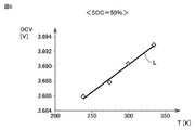
図5は、SOC=15%における対象セルの絶対温度TとOCVとの間の関係を示す図である。図6は、SOC=50%における対象セルの絶対温度TとOCVとの間の関係を示す図である。図5および図6において、横軸は対象セルの絶対温度Tを表し、縦軸は対象セルのOCVを表す。図5および図6に示すように、S102〜S109にて測定したデータ(対象セルの絶対温度TとOCVとの組合せ)をプロットすると、データは直線状に分布する。 FIG. 5 is a diagram showing the relationship between the absolute temperature T of the target cell and OCV at SOC = 15%. FIG. 6 is a diagram showing the relationship between the absolute temperature T of the target cell and OCV at SOC = 50%. In FIGS. 5 and 6, the horizontal axis represents the absolute temperature T of the target cell, and the vertical axis represents the OCV of the target cell. As shown in FIGS. 5 and 6, when the data measured in S102 to S109 (combination of the absolute temperature T of the target cell and OCV) is plotted, the data is distributed linearly.
図4を再び参照して、S111において、S110にてプロットしたデータを直線で近似し、近似直線Lの傾きを算出する。近似直線Lの傾き(=dEemp/dT)は、上記式(7)より、ΔS/nFと等しい。したがって、近似直線Lの傾きからエントロピー変化ΔSを算出できる。 With reference to FIG. 4 again, in S111, the data plotted in S110 is approximated by a straight line, and the slope of the approximate straight line L is calculated. The slope of the approximate straight line L (= dE emp / dT) is equal to ΔS / nF from the above equation (7). Therefore, the entropy change ΔS can be calculated from the slope of the approximate straight line L.
ファラデー定数Fは正値であるので、近似直線Lの傾きの正負と、エントロピー変化ΔSの符号とは一致する。SOC=15%の場合(図5参照)、近似直線Lの傾きは負であり、このときのエントロピー変化ΔSも負である。一方、SOC=50%の場合(図6参照)、近似直線Lの傾きは正であり、このときのエントロピー変化ΔSも正である。 Since the Faraday constant F is a positive value, the sign of the slope of the approximate straight line L and the sign of the entropy change ΔS match. When SOC = 15% (see FIG. 5), the slope of the approximate straight line L is negative, and the entropy change ΔS at this time is also negative. On the other hand, when SOC = 50% (see FIG. 6), the slope of the approximate straight line L is positive, and the entropy change ΔS at this time is also positive.
図5および図6では、2通りのSOCにおけるエントロピー変化ΔSの算出結果しか例示していない。しかし、様々なSOCに対しても同様に絶対温度TとOCVとの間の相関関係を測定し、その測定結果をグラフ上にプロットすることで、エントロピー変化ΔSのSOC依存性を求めることができる。 In FIGS. 5 and 6, only the calculation results of the entropy change ΔS in the two types of SOC are illustrated. However, the SOC dependence of the entropy change ΔS can be obtained by similarly measuring the correlation between the absolute temperature T and OCV for various SOCs and plotting the measurement results on a graph. ..
図7は、バッテリ2のエントロピー変化ΔSのSOC依存性の一例を示す図である。図7において、横軸はバッテリ2のSOCを表し、縦軸はバッテリ2のエントロピー変化ΔSを表す。バッテリ2のSOCがSLまたはSH(ただし、SL<SH)ある場合に、バッテリ2のエントロピー変化ΔSが0になる。図7に示す例では、SL=約25%であり、SH=約65%である。
FIG. 7 is a diagram showing an example of SOC dependence of the entropy change ΔS of the
バッテリ2のSOCが中SOC領域(SL以上かつSH以下のSOC領域)ではエントロピー変化ΔSは正である。一方、バッテリ2のSOCが低SOC領域(SL未満のSOC領域)または高SOC領域(SH超のSOC領域)である場合にはエントロピー変化ΔSは負である。なお、低SOC領域、中SOC領域および高SOC領域は、本開示に係る「第1のSOC領域」〜「第3のSOC領域」にそれぞれ相当する。
SOC is medium SOC region of the
<充電電流の制御>
本実施の形態においては、バッテリ2に充電可能な最大電流(以下、「最大充電電流」とも称する)Imaxがバッテリ2のエントロピー変化ΔSに応じて定められる。図4〜図7にて説明したように、バッテリ2のエントロピー変化ΔSとSOCとの間の関係を予め求めることが可能である。したがって、バッテリ2のSOCに応じてバッテリ2への最大充電電流Imaxを決定できる。
<Control of charging current>
In the present embodiment, the maximum current that can be charged to the battery 2 (hereinafter, also referred to as “maximum charging current”) Imax is determined according to the entropy change ΔS of the
図8は、バッテリ2への最大充電電流Imaxとバッテリ2のSOCとの間の関係を示す図である。図8(および後述する図12)において、横軸はバッテリ2のSOC[%]を表す。上の縦軸は、バッテリ2のエントロピー変化ΔSを表す。これは、図7にて説明済みのグラフを見易さのため再度示したものである。下の縦軸は、バッテリ2への最大充電電流Imax[A]を表す。なお、バッテリ2に入出力される電流Iの符号に関しては、バッテリ2への充電方向を正と定めている。
FIG. 8 is a diagram showing the relationship between the maximum charging current Imax to the
本実施の形態においては図8に示すように、バッテリ2のエントロピー変化ΔSが大きいほど最大充電電流Imaxが大きく決定される。たとえば、バッテリ2のSOC=50%付近であって、エントロピー変化ΔSが約10[J/K](第1の値)である場合における最大充電電流Imaxは、バッテリ2のSOC=20%付近であってバッテリ2のエントロピー変化ΔSが約−5[J/K](第2の値)である場合における最大充電電流Imaxよりも大きい。また、エントロピー変化ΔSが正であるSOC領域(中SOC領域)では、エントロピー変化ΔSが負であるSOC領域(低SOC領域または高SOC領域)と比べて、最大充電電流Imaxが大きい。図8に示すような関係が予め規定され、ECU10のメモリ102に格納されている。
In the present embodiment, as shown in FIG. 8, the larger the entropy change ΔS of the
上記式(5)に表されるように、エントロピー変化ΔSと反応ギブスエネルギーΔGの温度微分とは、異符号である。また、バッテリ2の充電時には基本的に、バッテリ2の発熱に伴いバッテリ2の温度TBが上昇する(dT>0)。この場合、エントロピー変化ΔSと反応ギブスエネルギーΔGの変化(d(ΔG))とは、異符号になる。よって、エントロピー変化ΔSが正である場合、反応ギブスエネルギーΔGは減少する。一般に、反応ギブスエネルギーΔGが減少する反応は、自発的に起こりやすい。この例では具体的に、電解液中のリチウムイオンが負極内に取り込まれやすくなる。その結果、バッテリ2の内部抵抗が上昇しにくくなると考えられる。
As represented by the above equation (5), the entropy change ΔS and the temperature derivative of the reaction Gibbs energy ΔG have different signs. Further, when the
このように、エントロピー変化ΔSが正であるSOC領域においては、エントロピー変化ΔSが負であるSOC領域と比べて、バッテリ2の内部抵抗が上昇しにくい。したがって、エントロピー変化ΔSが正であるSOC領域では、最大充電電流Imaxを相対的に大きくしたとしても、バッテリ2の内部抵抗の上昇レートを許容範囲内に収めることができる。よって、本実施の形態によれば、充電時間の短縮とバッテリ2の充電に伴う劣化の抑制とを両立できる。
As described above, in the SOC region where the entropy change ΔS is positive, the internal resistance of the
<充電制御フロー>
図9は、本実施の形態におけるバッテリ2の充電方法を示すフローチャートである。このフローチャートは、規定の制御周期が経過する度にメインルーチン(図示せず)から呼び出されて実行される。各ステップは、基本的にはECU10によるソフトウェア処理によって実現されるが、ECU10内に作製された電子回路によるハードウェア処理によって実現されてもよい。以下ではステップを「S」と略す。
<Charge control flow>
FIG. 9 is a flowchart showing a charging method of the
S201において、ECU10は、バッテリ2のプラグイン充電を行うかどうかを判定する。具体的には、充電ケーブル99がインレット11に接続されている場合(プラグイン充電の開始直前である場合または既にプラグイン充電中である場合)に、ECU10は、S201にてYESと判定できる。バッテリ2のプラグイン充電を行わない場合(S201においてNO)、ECU10は、以降の処理をスキップして処理をメインルーチンに戻す。
In S201, the
S202において、ECU10は、バッテリ2に充電すべき電流Iを算出する。より詳細には、ECU10は、充電設備900の制御回路92との交渉により、バッテリ2に充電する電流パターンを決定する。決定した電流パターンに基づき、ECU10は、現時刻の充電電流I(これから充電すべき電流)を算出する。
In S202, the
S203において、ECU10は、バッテリ2の電圧VBおよび電流IBのうちの少なくとも一方に基づいて、バッテリ2のSOCを推定する。SOCの推定手法としては、予め求められたSOC−OCV特性曲線を用いる手法、または、バッテリ2に入出力される電流を積算する手法などの公知の手法を採用できる。
In S203, the
S204において、ECU10は、バッテリ2のSOCと最大充電電流Imaxとの間の関係を示すマップ(たとえば図8の下図参照)を参照することで、バッテリ2のSOCからバッテリ2への最大充電電流Imaxを決定する。これにより、バッテリ2への最大充電電流Imaxがバッテリ2のエントロピー変化ΔSに応じて決定されることとなる。
In S204, the
S205において、ECU10は、バッテリ2への充電電流Iを最大充電電流Imaxにより制限する。具体的には、ECU10は、バッテリ2への充電電流I(S202にて算出した値)が最大充電電流Imax以上である場合には、バッテリ2への充電電流Iを最大充電電流Imaxに置き換える(I=Imax)。一方、ECU10は、バッテリ2への充電電流Iが最大充電電流Imax未満である場合には、バッテリ2への充電電流Iをそのまま用いる。
In S205, the
S206において、ECU10は、S25にて制限した充電電流Iがバッテリ2に充電されるように、バッテリ2のプラグイン充電制御を実行する。たとえば車両100のプラグイン充電時には、バッテリ2の充電条件に関するパラメータが車両100と充電設備900との間で授受される。この際に、ECU10は、充電設備900から車両100に供給を要求する電流値(または受け取り可能な最大電流値)をS205にて算出した値に設定する。その後、処理がメインルーチンに戻されることで、規定の制御周期毎に一連の処理が繰り返される。
In S206, the
<評価試験の結果>
続いて、本実施の形態に係るバッテリ2の充電方法を評価するために実施した試験結果について説明する。この評価試験では、SOCを規定値(この例では10%)に調整したバッテリ2を2つ準備した。一方のバッテリ2を一般的な充電パターン(比較例)で繰り返し充電し、もう一方のバッテリ2を本実施の形態における充電パターンで繰り返し充電した。充電の繰り返し数(サイクル数)は100回とした。そして、充電に伴うバッテリ2の劣化の進行度合いをバッテリ2の内部抵抗の変化率(抵抗変化率)によって定量的に評価した。
<Result of evaluation test>
Subsequently, the test results carried out for evaluating the charging method of the
図10は、評価試験に使用した充電電流パターンを示すタイムチャートである。図10において、横軸は、バッテリ2の充電を開始してからの経過時間を表す。上の縦軸は比較例におけるバッテリ2への充電電流Iを表し、下の縦軸は本実施の形態におけるバッテリ2への充電電流Iを表す。この例では、各セル21に充電される値が充電電流Iとして示されている。
FIG. 10 is a time chart showing the charging current pattern used in the evaluation test. In FIG. 10, the horizontal axis represents the elapsed time from the start of charging the
図9を参照して、比較例では、バッテリ2への充電電流Iが充電開始時に最も大きかった。バッテリ2の充電が進むに従って充電電流Iを次第に(この例では段階的に)減少させた。
With reference to FIG. 9, in the comparative example, the charging current I to the
これに対し、本実施の形態においては、充電開始時にはバッテリ2への充電電流Iを相対的に小さな値(50A以下)に制限した。この制限された状態での充電を約7分間継続してから充電電流Iを増大させた。本実施の形態におけるバッテリに充電した電流の最大値は、比較例における最大値と等しかった(約130A)。その後、バッテリ2の充電が進むと、比較例と同様に充電電流Iを減少させた。
On the other hand, in the present embodiment, the charging current I to the
図11は、図10にて説明した充電電流パターンに従って充電を繰り返した場合のバッテリ2の抵抗変化率の評価結果の一例を示す図である。図11において、横軸は充電サイクル数を表す。縦軸は、バッテリ2の抵抗変化率を表す。なお、抵抗変化率とは、充電開始前の内部抵抗に対する充電開始後の内部抵抗の比率[%]である。
FIG. 11 is a diagram showing an example of an evaluation result of the resistance change rate of the
図11を参照して、充電サイクル数が同じ条件同士で比較すると、比較例におけるバッテリ2の抵抗変化率の上昇量に対して本実施の形態におけるバッテリ2の抵抗変化率の上昇量が有意に小さいことが分かる。以下に説明するように、図10および図11に示した結果以外にも様々な評価試験を実施した。
When comparing the conditions with the same number of charging cycles with reference to FIG. 11, the amount of increase in the resistance change rate of the
図12は、評価試験の条件を説明するための図である。図12を参照して、この評価試験では、バッテリ2への充電電流(充電電流=最大充電電流Imax)をSOC領域毎に1通りに設定した。図中、低SOC領域における充電電流をILと記載し、中SOC領域における充電電流をIMと記載し、高SOC領域における充電電流をIHと記載している。そのため、充電に伴いバッテリ2のSOCが増加するに従って充電電流がステップ的に増加する。しかし、充電電流をステップ的に増加させることは必須ではなく、充電電流を滑らかに(連続的に)変化させてもよい。
FIG. 12 is a diagram for explaining the conditions of the evaluation test. With reference to FIG. 12, in this evaluation test, the charging current (charging current = maximum charging current Imax) to the
図13は、評価試験の結果をまとめた図である。図13には、本実施の形態における5つの実施例1〜5と、2つの比較例1,2とについて、バッテリ2に印可された電流パターンと、それによるバッテリ2の抵抗変化率の測定結果とがまとめられている。なお、図13における充電電流とは、バッテリ2への充電電流(図12の縦軸参照)をCレートに換算した値である。
FIG. 13 is a diagram summarizing the results of the evaluation test. FIG. 13 shows the measurement results of the current pattern applied to the
図13を参照して、比較例1,2では、バッテリ2のエントロピー変化ΔSが負である場合(バッテリ2のSOCが低SOC領域または高SOC領域に含まれる場合)に、バッテリ2への充電電流を大きくしたため、100回の充電サイクル後のバッテリ2の抵抗変化率が大きく上昇した。具体的に、バッテリ2への充電電流Iが2.0C以上であるときには、バッテリ2の抵抗変化率の上昇量が特に大きくなり、約250%(243%または264%)に至った。
With reference to FIG. 13, in Comparative Examples 1 and 2, when the entropy change ΔS of the
これに対し、実施例1〜5においては、バッテリ2のエントロピー変化ΔSが正である場合(バッテリ2のSOCが中SOC領域に含まれる場合)、バッテリ2への充電電流(=最大充電電流Imax)のCレートを1.5C以上に設定した。さらに、エントロピー変化ΔSが正である場合のバッテリ2への充電電流を、エントロピー変化ΔSが負である場合のバッテリ2への充電電流の1.25倍以上に設定した。これにより、充電時間を短縮しつつ、バッテリ2の抵抗変化率を110%程度に抑えることが可能であった。
On the other hand, in Examples 1 to 5, when the entropy change ΔS of the
以上のように、本実施の形態においては、バッテリ2への最大充電電流Imaxをバッテリ2のSOCに応じて決定する。バッテリ2のSOCとエントロピー変化ΔSとの間の関係(図7参照)が予め求められているので、最大充電電流Imaxをバッテリ2のSOCに応じて決定することは、最大充電電流Imaxをバッテリ2のエントロピー変化ΔSに応じて決定することを意味する。エントロピー変化Δが正である場合には、反応ギブスエネルギーΔGが負になる(上記式(5)参照)。そのため、エントロピー変化Δが正であるSOC領域においては、インターカレーション反応が進行しやすく、バッテリ2の内部抵抗が上昇しにくい。したがって、バッテリ2のエントロピー変化ΔSが正であるSOC領域(中SOC領域)では、バッテリ2のエントロピー変化ΔSが負であるSOC領域(低SOC領域または高SOC領域)と比べて、バッテリ2への最大充電電流Imaxを大きくしても、バッテリ2の劣化を好適に抑制できる。
As described above, in the present embodiment, the maximum charging current Imax to the
今回開示された実施の形態は、すべての点で例示であって制限的なものではないと考えられるべきである。本開示の範囲は、上記した実施の形態の説明ではなくて特許請求の範囲によって示され、特許請求の範囲と均等の意味および範囲内でのすべての変更が含まれることが意図される。 The embodiments disclosed this time should be considered to be exemplary in all respects and not restrictive. The scope of the present disclosure is shown by the scope of claims rather than the description of the embodiment described above, and is intended to include all modifications within the meaning and scope equivalent to the scope of claims.
1 充電システム、100 車両、11 インレット、12 電圧センサ、13 電流センサ、14 充電リレー、2 バッテリ、21 セル、211 電池ケース、212 蓋体、213 正極端子、214 負極端子、215 電極体、3 監視ユニット、31 電圧センサ、32 電流センサ、33 温度センサ、4 SMR、5 PCU、61,62 モータジェネレータ、7 エンジン、81 動力分割装置、82 駆動軸、83 駆動輪、10 ECU、101 プロセッサ、102 メモリ、900 充電設備、91 AC/DC変換器、92 制御回路、99 充電ケーブル、991 コネクタ、ACL 電力線、NL1,PL1 充電線、NL9,PL9 給電線。 1 charging system, 100 vehicles, 11 inlets, 12 voltage sensors, 13 current sensors, 14 charging relays, 2 batteries, 21 cells, 211 battery cases, 212 lids, 213 positive terminals, 214 negative terminals, 215 electrodes, 3 monitoring Unit, 31 voltage sensor, 32 current sensor, 33 temperature sensor, 4 SMR, 5 PCU, 61, 62 motor generator, 7 engine, 81 power divider, 82 drive shaft, 83 drive wheel, 10 ECU, 101 processor, 102 memory , 900 charging equipment, 91 AC / DC converter, 92 control circuit, 99 charging cable, 991 connector, ACL power line, NL1, PL1 charging line, NL9, PL9 power supply line.
Claims (6)
前記電池の電圧および電流のうちの少なくとも一方に基づいて前記電池のSOCを推定するステップと、
前記電池のSOCと前記電池の電池反応のエントロピー変化との間の関係に基づき、前記電池のエントロピー変化が大きいほど前記電池への充電電流が大きくなるように、前記充電電流を前記電池のSOCに応じて決定するステップとを含む、電池の充電方法。 It is a method of charging a battery that is a non-aqueous electrolyte secondary battery.
A step of estimating the SOC of the battery based on at least one of the voltage and current of the battery.
Based on the relationship between the SOC of the battery and the change in the entropy of the battery reaction of the battery, the charging current is transferred to the SOC of the battery so that the larger the change in the entropy of the battery, the larger the charging current to the battery. How to charge the battery, including steps to determine accordingly.
前記決定するステップは、前記電池のSOCが前記第2のSOC領域に含まれる場合には、前記電池のSOCが前記第1および第3のSOC領域のうちのいずれかに含まれる場合と比べて、前記充電電流を大きくするステップを含む、請求項1または2に記載の電池の充電方法。 The change in entropy of the battery is negative in the first SOC region, positive in the second SOC region higher than the first SOC region, and even higher than the second SOC region in the third SOC. Negative in the realm,
The determination step is performed when the SOC of the battery is included in the second SOC region, as compared with the case where the SOC of the battery is included in any of the first and third SOC regions. The method for charging a battery according to claim 1 or 2, which comprises the step of increasing the charging current.
前記電池のエントロピー変化が正であるSOC領域では、前記充電電流のCレートを1.5C以上にし、かつ、
前記電池のエントロピー変化が正であるSOC領域における前記充電電流を、前記電池のエントロピー変化が負であるSOC領域における前記充電電流の1.25倍以上にするステップを含む、請求項1〜3のいずれか1項に記載の電池の充電方法。 The step to determine is
In the SOC region where the entropy change of the battery is positive, the C rate of the charging current is set to 1.5C or more, and the charging current is set to 1.5C or more.
Claims 1 to 3 include the step of increasing the charging current in the SOC region where the entropy change of the battery is positive to 1.25 times or more the charging current in the SOC region where the entropy change of the battery is negative. The method for charging the battery according to any one item.
前記電池の電圧および電流のうちの少なくとも一方に基づいて前記電池のSOCを推定するステップと、
前記電池のSOCと前記電池の電池反応のエントロピー変化との間の関係に基づき、前記電池への充電電流を前記電池のSOCに応じて決定するステップとを含み、
前記電池のエントロピー変化が第1の値である場合における前記電池への充電電流は、前記電池のエントロピー変化が前記第1の値よりも小さな第2の値である場合における前記充電電流よりも大きい、電池の充電方法。 It is a method of charging a battery that is a non-aqueous electrolyte secondary battery.
A step of estimating the SOC of the battery based on at least one of the voltage and current of the battery.
Including a step of determining the charging current to the battery according to the SOC of the battery based on the relationship between the SOC of the battery and the entropy change of the battery reaction of the battery.
The charging current to the battery when the entropy change of the battery is the first value is larger than the charging current when the entropy change of the battery is a second value smaller than the first value. , How to charge the battery.
前記電池を充電するように構成された充電装置と、
前記電池への充電電流を制御する制御装置とを備え、
前記制御装置は、
前記電池の電圧および電流のうちの少なくとも一方に基づいて前記電池のSOCを推定し、
前記電池のSOCと前記電池の電池反応のエントロピー変化との間の関係に基づき、前記電池のエントロピー変化が大きいほど前記充電電流が大きくなるように、前記充電電流を前記電池のSOCに応じて決定する、充電システム。 Batteries that are non-aqueous electrolyte secondary batteries and
A charging device configured to charge the battery and
A control device for controlling the charging current to the battery is provided.
The control device is
The SOC of the battery is estimated based on at least one of the voltage and current of the battery.
Based on the relationship between the SOC of the battery and the change in the entropy of the battery reaction of the battery, the charging current is determined according to the SOC of the battery so that the larger the change in the entropy of the battery, the larger the charging current. The charging system.
Priority Applications (5)
| Application Number | Priority Date | Filing Date | Title |
|---|---|---|---|
| JP2019207256A JP7151692B2 (en) | 2019-11-15 | 2019-11-15 | Battery charging method and charging system |
| EP20206425.9A EP3823078A1 (en) | 2019-11-15 | 2020-11-09 | Method for charging battery and charging system |
| KR1020200150905A KR102526575B1 (en) | 2019-11-15 | 2020-11-12 | Method for charging battery and charging system |
| CN202011258591.4A CN112820957A (en) | 2019-11-15 | 2020-11-12 | Battery charging method and charging system |
| US17/097,258 US11495981B2 (en) | 2019-11-15 | 2020-11-13 | Method for charging battery and charging system |
Applications Claiming Priority (1)
| Application Number | Priority Date | Filing Date | Title |
|---|---|---|---|
| JP2019207256A JP7151692B2 (en) | 2019-11-15 | 2019-11-15 | Battery charging method and charging system |
Publications (2)
| Publication Number | Publication Date |
|---|---|
| JP2021082425A true JP2021082425A (en) | 2021-05-27 |
| JP7151692B2 JP7151692B2 (en) | 2022-10-12 |
Family
ID=73198162
Family Applications (1)
| Application Number | Title | Priority Date | Filing Date |
|---|---|---|---|
| JP2019207256A Active JP7151692B2 (en) | 2019-11-15 | 2019-11-15 | Battery charging method and charging system |
Country Status (5)
| Country | Link |
|---|---|
| US (1) | US11495981B2 (en) |
| EP (1) | EP3823078A1 (en) |
| JP (1) | JP7151692B2 (en) |
| KR (1) | KR102526575B1 (en) |
| CN (1) | CN112820957A (en) |
Families Citing this family (2)
| Publication number | Priority date | Publication date | Assignee | Title |
|---|---|---|---|---|
| KR20230019315A (en) * | 2021-07-29 | 2023-02-08 | 현대자동차주식회사 | Method and system for estimating degradation of battery for vehicle |
| CN114189013A (en) * | 2021-11-30 | 2022-03-15 | 华为数字能源技术有限公司 | Charging device, charging method and computer readable storage medium |
Citations (2)
| Publication number | Priority date | Publication date | Assignee | Title |
|---|---|---|---|---|
| US20170229891A1 (en) * | 2016-02-05 | 2017-08-10 | Korea Advanced Institute Of Science And Technology | Optimized battery charging method based on thermodynamic information of battery |
| JP2018046667A (en) * | 2016-09-14 | 2018-03-22 | 株式会社東芝 | Charging pattern creation device, charging control device, charging pattern creation method, program, and power storage system |
Family Cites Families (10)
| Publication number | Priority date | Publication date | Assignee | Title |
|---|---|---|---|---|
| US8754614B2 (en) | 2009-07-17 | 2014-06-17 | Tesla Motors, Inc. | Fast charging of battery using adjustable voltage control |
| JP2011113688A (en) | 2009-11-25 | 2011-06-09 | Sanyo Electric Co Ltd | Method for detecting condition of secondary battery |
| US20170294689A1 (en) * | 2014-06-24 | 2017-10-12 | Kabushiki Kaisha Toshiba | Battery-system-deterioration control device, and method thereof |
| KR102255130B1 (en) * | 2014-07-16 | 2021-05-24 | 삼성전자주식회사 | Electronic device and method for controlling charging of battery |
| DE102014223263A1 (en) * | 2014-11-14 | 2016-05-19 | Robert Bosch Gmbh | Device and method for cooling a battery cell and battery module, battery, battery system, vehicle, computer program and computer program product |
| JP2017010882A (en) * | 2015-06-25 | 2017-01-12 | トヨタ自動車株式会社 | Secondary battery system |
| KR101805514B1 (en) * | 2015-11-20 | 2017-12-07 | 한국과학기술원 | Method of dynamically extracting entropy on battery |
| US9966769B2 (en) * | 2015-11-24 | 2018-05-08 | The Johns Hopkins University | Capacity independent fast charging of batteries |
| WO2019162749A1 (en) * | 2017-12-07 | 2019-08-29 | Yazami Ip Pte. Ltd. | Method and system for online assessing state of health of a battery |
| JP6798586B2 (en) | 2019-08-06 | 2020-12-09 | 三菱電機株式会社 | RF signal recording / playback device and RF signal recording / playback method |
-
2019
- 2019-11-15 JP JP2019207256A patent/JP7151692B2/en active Active
-
2020
- 2020-11-09 EP EP20206425.9A patent/EP3823078A1/en active Pending
- 2020-11-12 KR KR1020200150905A patent/KR102526575B1/en active IP Right Grant
- 2020-11-12 CN CN202011258591.4A patent/CN112820957A/en active Pending
- 2020-11-13 US US17/097,258 patent/US11495981B2/en active Active
Patent Citations (2)
| Publication number | Priority date | Publication date | Assignee | Title |
|---|---|---|---|---|
| US20170229891A1 (en) * | 2016-02-05 | 2017-08-10 | Korea Advanced Institute Of Science And Technology | Optimized battery charging method based on thermodynamic information of battery |
| JP2018046667A (en) * | 2016-09-14 | 2018-03-22 | 株式会社東芝 | Charging pattern creation device, charging control device, charging pattern creation method, program, and power storage system |
Also Published As
| Publication number | Publication date |
|---|---|
| US11495981B2 (en) | 2022-11-08 |
| CN112820957A (en) | 2021-05-18 |
| US20210152001A1 (en) | 2021-05-20 |
| KR102526575B1 (en) | 2023-04-28 |
| KR20210059636A (en) | 2021-05-25 |
| EP3823078A1 (en) | 2021-05-19 |
| JP7151692B2 (en) | 2022-10-12 |
Similar Documents
| Publication | Publication Date | Title |
|---|---|---|
| US9013138B2 (en) | Charging apparatus for electric storage device, vehicle equipped with the charging apparatus, and method of controlling the charging apparatus | |
| JP6863258B2 (en) | Stress estimation method for secondary battery system and active material of secondary battery | |
| US20160020618A1 (en) | Fast Charge Algorithms for Lithium-Ion Batteries | |
| CN110289455B (en) | Secondary battery system and method for estimating deterioration state of secondary battery | |
| US10483598B2 (en) | Lithium replenishment cell to enhance beginning of life capacity | |
| EP3823065A1 (en) | Method for charging battery and charging system | |
| US10862174B2 (en) | Secondary battery system and method of estimating deterioration state of secondary battery system | |
| JP2019105521A (en) | Secondary battery system and soc estimation method of secondary battery | |
| KR102526575B1 (en) | Method for charging battery and charging system | |
| CN110879366B (en) | Secondary battery system and method for estimating SOC of secondary battery | |
| JP7131002B2 (en) | Secondary battery deterioration estimation device | |
| JP7020095B2 (en) | Rechargeable battery system | |
| JP2020068568A (en) | Secondary battery system and charge control method of secondary battery | |
| JP7409026B2 (en) | Estimation system | |
| JP5923831B2 (en) | Lithium ion secondary battery control system, battery system, and mobile body and power storage system including the same | |
| CN113036834A (en) | Battery system and control method of lithium ion battery | |
| JP2020134355A (en) | Battery system | |
| JP2020087772A (en) | Charging system | |
| JP7120938B2 (en) | BATTERY SYSTEM AND SECONDARY BATTERY CONTROL METHOD | |
| JP7040408B2 (en) | Rechargeable battery system | |
| JP7095664B2 (en) | Rechargeable battery system | |
| JP7409025B2 (en) | Estimation system | |
| US11189865B2 (en) | Deterioration estimation device for secondary battery, and deterioration estimation method for secondary battery | |
| JP2018133295A (en) | Secondary battery system | |
| JP2021089801A (en) | vehicle |
Legal Events
| Date | Code | Title | Description |
|---|---|---|---|
| A621 | Written request for application examination |
Free format text: JAPANESE INTERMEDIATE CODE: A621 Effective date: 20211119 |
|
| TRDD | Decision of grant or rejection written | ||
| A01 | Written decision to grant a patent or to grant a registration (utility model) |
Free format text: JAPANESE INTERMEDIATE CODE: A01 Effective date: 20220830 |
|
| A977 | Report on retrieval |
Free format text: JAPANESE INTERMEDIATE CODE: A971007 Effective date: 20220831 |
|
| A61 | First payment of annual fees (during grant procedure) |
Free format text: JAPANESE INTERMEDIATE CODE: A61 Effective date: 20220912 |
|
| R151 | Written notification of patent or utility model registration |
Ref document number: 7151692 Country of ref document: JP Free format text: JAPANESE INTERMEDIATE CODE: R151 |