JP2021081886A - On-vehicle measurement device unit and integrated data generation method in on-vehicle measurement device unit - Google Patents
On-vehicle measurement device unit and integrated data generation method in on-vehicle measurement device unit Download PDFInfo
- Publication number
- JP2021081886A JP2021081886A JP2019207578A JP2019207578A JP2021081886A JP 2021081886 A JP2021081886 A JP 2021081886A JP 2019207578 A JP2019207578 A JP 2019207578A JP 2019207578 A JP2019207578 A JP 2019207578A JP 2021081886 A JP2021081886 A JP 2021081886A
- Authority
- JP
- Japan
- Prior art keywords
- vehicle
- detectors
- data
- measuring device
- device unit
- Prior art date
- Legal status (The legal status is an assumption and is not a legal conclusion. Google has not performed a legal analysis and makes no representation as to the accuracy of the status listed.)
- Pending
Links
- 238000000034 method Methods 0.000 title claims description 23
- 238000005259 measurement Methods 0.000 title abstract 5
- 238000001514 detection method Methods 0.000 claims abstract description 50
- 238000012545 processing Methods 0.000 claims description 56
- 230000007613 environmental effect Effects 0.000 claims description 14
- 238000004891 communication Methods 0.000 description 22
- 230000005540 biological transmission Effects 0.000 description 11
- 230000008569 process Effects 0.000 description 8
- 230000009467 reduction Effects 0.000 description 6
- 230000007246 mechanism Effects 0.000 description 4
- 239000007769 metal material Substances 0.000 description 4
- 238000006243 chemical reaction Methods 0.000 description 3
- 238000010586 diagram Methods 0.000 description 3
- 230000006870 function Effects 0.000 description 3
- 239000011347 resin Substances 0.000 description 3
- 229920005989 resin Polymers 0.000 description 3
- 238000002485 combustion reaction Methods 0.000 description 2
- 238000004590 computer program Methods 0.000 description 2
- 238000013461 design Methods 0.000 description 2
- 230000000694 effects Effects 0.000 description 2
- 238000012986 modification Methods 0.000 description 2
- 230000004048 modification Effects 0.000 description 2
- 229910052755 nonmetal Inorganic materials 0.000 description 2
- 229920000049 Carbon (fiber) Polymers 0.000 description 1
- 241000533950 Leucojum Species 0.000 description 1
- 229910052782 aluminium Inorganic materials 0.000 description 1
- XAGFODPZIPBFFR-UHFFFAOYSA-N aluminium Chemical compound [Al] XAGFODPZIPBFFR-UHFFFAOYSA-N 0.000 description 1
- 238000013459 approach Methods 0.000 description 1
- 230000008901 benefit Effects 0.000 description 1
- 239000004917 carbon fiber Substances 0.000 description 1
- 230000006835 compression Effects 0.000 description 1
- 238000007906 compression Methods 0.000 description 1
- 238000003702 image correction Methods 0.000 description 1
- 230000010354 integration Effects 0.000 description 1
- 238000010801 machine learning Methods 0.000 description 1
- 230000007257 malfunction Effects 0.000 description 1
- VNWKTOKETHGBQD-UHFFFAOYSA-N methane Chemical compound C VNWKTOKETHGBQD-UHFFFAOYSA-N 0.000 description 1
- 238000012544 monitoring process Methods 0.000 description 1
- 230000003287 optical effect Effects 0.000 description 1
- 230000004044 response Effects 0.000 description 1
- 238000007789 sealing Methods 0.000 description 1
- 230000011664 signaling Effects 0.000 description 1
- 229910001220 stainless steel Inorganic materials 0.000 description 1
- 239000010935 stainless steel Substances 0.000 description 1
- 238000012546 transfer Methods 0.000 description 1
- XLYOFNOQVPJJNP-UHFFFAOYSA-N water Chemical compound O XLYOFNOQVPJJNP-UHFFFAOYSA-N 0.000 description 1
Images


Classifications
-
- B—PERFORMING OPERATIONS; TRANSPORTING
- B60—VEHICLES IN GENERAL
- B60W—CONJOINT CONTROL OF VEHICLE SUB-UNITS OF DIFFERENT TYPE OR DIFFERENT FUNCTION; CONTROL SYSTEMS SPECIALLY ADAPTED FOR HYBRID VEHICLES; ROAD VEHICLE DRIVE CONTROL SYSTEMS FOR PURPOSES NOT RELATED TO THE CONTROL OF A PARTICULAR SUB-UNIT
- B60W50/00—Details of control systems for road vehicle drive control not related to the control of a particular sub-unit, e.g. process diagnostic or vehicle driver interfaces
-
- G—PHYSICS
- G08—SIGNALLING
- G08G—TRAFFIC CONTROL SYSTEMS
- G08G1/00—Traffic control systems for road vehicles
- G08G1/16—Anti-collision systems
- G08G1/166—Anti-collision systems for active traffic, e.g. moving vehicles, pedestrians, bikes
-
- B—PERFORMING OPERATIONS; TRANSPORTING
- B60—VEHICLES IN GENERAL
- B60R—VEHICLES, VEHICLE FITTINGS, OR VEHICLE PARTS, NOT OTHERWISE PROVIDED FOR
- B60R11/00—Arrangements for holding or mounting articles, not otherwise provided for
- B60R11/02—Arrangements for holding or mounting articles, not otherwise provided for for radio sets, television sets, telephones, or the like; Arrangement of controls thereof
-
- G—PHYSICS
- G01—MEASURING; TESTING
- G01S—RADIO DIRECTION-FINDING; RADIO NAVIGATION; DETERMINING DISTANCE OR VELOCITY BY USE OF RADIO WAVES; LOCATING OR PRESENCE-DETECTING BY USE OF THE REFLECTION OR RERADIATION OF RADIO WAVES; ANALOGOUS ARRANGEMENTS USING OTHER WAVES
- G01S13/00—Systems using the reflection or reradiation of radio waves, e.g. radar systems; Analogous systems using reflection or reradiation of waves whose nature or wavelength is irrelevant or unspecified
- G01S13/86—Combinations of radar systems with non-radar systems, e.g. sonar, direction finder
-
- G—PHYSICS
- G01—MEASURING; TESTING
- G01S—RADIO DIRECTION-FINDING; RADIO NAVIGATION; DETERMINING DISTANCE OR VELOCITY BY USE OF RADIO WAVES; LOCATING OR PRESENCE-DETECTING BY USE OF THE REFLECTION OR RERADIATION OF RADIO WAVES; ANALOGOUS ARRANGEMENTS USING OTHER WAVES
- G01S13/00—Systems using the reflection or reradiation of radio waves, e.g. radar systems; Analogous systems using reflection or reradiation of waves whose nature or wavelength is irrelevant or unspecified
- G01S13/88—Radar or analogous systems specially adapted for specific applications
- G01S13/93—Radar or analogous systems specially adapted for specific applications for anti-collision purposes
- G01S13/931—Radar or analogous systems specially adapted for specific applications for anti-collision purposes of land vehicles
-
- G—PHYSICS
- G01—MEASURING; TESTING
- G01V—GEOPHYSICS; GRAVITATIONAL MEASUREMENTS; DETECTING MASSES OR OBJECTS; TAGS
- G01V11/00—Prospecting or detecting by methods combining techniques covered by two or more of main groups G01V1/00 - G01V9/00
-
- G—PHYSICS
- G07—CHECKING-DEVICES
- G07C—TIME OR ATTENDANCE REGISTERS; REGISTERING OR INDICATING THE WORKING OF MACHINES; GENERATING RANDOM NUMBERS; VOTING OR LOTTERY APPARATUS; ARRANGEMENTS, SYSTEMS OR APPARATUS FOR CHECKING NOT PROVIDED FOR ELSEWHERE
- G07C5/00—Registering or indicating the working of vehicles
- G07C5/02—Registering or indicating driving, working, idle, or waiting time only
-
- G—PHYSICS
- G08—SIGNALLING
- G08C—TRANSMISSION SYSTEMS FOR MEASURED VALUES, CONTROL OR SIMILAR SIGNALS
- G08C15/00—Arrangements characterised by the use of multiplexing for the transmission of a plurality of signals over a common path
- G08C15/06—Arrangements characterised by the use of multiplexing for the transmission of a plurality of signals over a common path successively, i.e. using time division
-
- G—PHYSICS
- G08—SIGNALLING
- G08C—TRANSMISSION SYSTEMS FOR MEASURED VALUES, CONTROL OR SIMILAR SIGNALS
- G08C19/00—Electric signal transmission systems
-
- B—PERFORMING OPERATIONS; TRANSPORTING
- B60—VEHICLES IN GENERAL
- B60W—CONJOINT CONTROL OF VEHICLE SUB-UNITS OF DIFFERENT TYPE OR DIFFERENT FUNCTION; CONTROL SYSTEMS SPECIALLY ADAPTED FOR HYBRID VEHICLES; ROAD VEHICLE DRIVE CONTROL SYSTEMS FOR PURPOSES NOT RELATED TO THE CONTROL OF A PARTICULAR SUB-UNIT
- B60W2420/00—Indexing codes relating to the type of sensors based on the principle of their operation
- B60W2420/40—Photo or light sensitive means, e.g. infrared sensors
- B60W2420/403—Image sensing, e.g. optical camera
-
- B60W2420/408—
-
- B—PERFORMING OPERATIONS; TRANSPORTING
- B60—VEHICLES IN GENERAL
- B60W—CONJOINT CONTROL OF VEHICLE SUB-UNITS OF DIFFERENT TYPE OR DIFFERENT FUNCTION; CONTROL SYSTEMS SPECIALLY ADAPTED FOR HYBRID VEHICLES; ROAD VEHICLE DRIVE CONTROL SYSTEMS FOR PURPOSES NOT RELATED TO THE CONTROL OF A PARTICULAR SUB-UNIT
- B60W2556/00—Input parameters relating to data
- B60W2556/35—Data fusion
-
- G—PHYSICS
- G08—SIGNALLING
- G08G—TRAFFIC CONTROL SYSTEMS
- G08G1/00—Traffic control systems for road vehicles
- G08G1/16—Anti-collision systems
Abstract
Description
本開示は車両に搭載して用いられる計測装置ユニットに関する。 The present disclosure relates to a measuring device unit mounted on a vehicle and used.
運転支援システムにおいては、複数のセンサが用いられる。複数のセンサを集約して車両に搭載する技術が提案されている(例えば、引用文献1)。 In the driving support system, a plurality of sensors are used. A technique has been proposed in which a plurality of sensors are integrated and mounted on a vehicle (for example, Cited Document 1).
しかしながら、多数のセンサを集約して計測装置ユニットとして車両に搭載する場合、各センサと車両内に備えられている運転支援システム用の制御装置との間における配線数が増大し、配線設計が複雑になるという問題がある。また、多数のセンサから送信されるデータを直接、運転支援システム用の制御装置に送信する場合にはデータを有効に活用できない場合がある。 However, when a large number of sensors are integrated and mounted on a vehicle as a measuring device unit, the number of wires between each sensor and the control device for a driving support system provided in the vehicle increases, and the wiring design is complicated. There is a problem of becoming. Further, when the data transmitted from a large number of sensors is directly transmitted to the control device for the driving support system, the data may not be effectively utilized.
したがって、計測装置ユニットと車両内の制御装置との間における配線数を低減することが求められている。 Therefore, it is required to reduce the number of wirings between the measuring device unit and the control device in the vehicle.
本開示は、以下の態様として実現することが可能である。 The present disclosure can be realized as the following aspects.
第1の態様は、車載用の計測装置ユニットを提供する。第1の態様に係る車載用の計測装置ユニットは、複数の検出器と、前記複数の検出器とそれぞれ接続されている複数の入力部と、車両内に配置されている制御装置と接続されている出力部と、前記複数の入力部を介して入力される前記複数の検出器からの検出データを用いて統合データを生成して前記出力部を介して出力する統合データ生成部と、を備える。 The first aspect provides an in-vehicle measuring device unit. The vehicle-mounted measuring device unit according to the first aspect is connected to a plurality of detectors, a plurality of input units connected to the plurality of detectors, and a control device arranged in the vehicle. The output unit includes an integrated data generation unit that generates integrated data using the detection data from the plurality of detectors input via the plurality of input units and outputs the integrated data via the output unit. ..
第1の態様に係る車載用の計測装置ユニットによれば、計測装置ユニットと車両内の制御装置との間における配線数を低減することができる。 According to the vehicle-mounted measuring device unit according to the first aspect, the number of wirings between the measuring device unit and the control device in the vehicle can be reduced.
第2の態様は、車載用の計測装置ユニットにおける統合データ生成方法を提供する。第2の態様に係るデータ送信方法は、複数の検出器から検出データを受信し、複数の前記検出データを用いて統合データを生成し、車両内に配置されている制御装置に対して送信すること、を備える。 The second aspect provides an integrated data generation method in an in-vehicle measuring device unit. The data transmission method according to the second aspect receives detection data from a plurality of detectors, generates integrated data using the plurality of detection data, and transmits the integrated data to a control device arranged in the vehicle. To be equipped.
第2の態様に係る車載用の計測装置ユニットにおける統合データ生成方法によれば、計測装置ユニットと車両内の制御装置との間における配線数を低減することができる。なお、本開示は、統合データ生成プログラムまたは当該プログラムを記録するコンピュータ読み取り可能記録媒体としても実現可能である。 According to the integrated data generation method in the vehicle-mounted measuring device unit according to the second aspect, the number of wirings between the measuring device unit and the control device in the vehicle can be reduced. The present disclosure can also be realized as an integrated data generation program or a computer-readable recording medium for recording the program.
本開示に係る車載用の計測装置ユニット、計測装置ユニットにおける統合データ生成方法について、いくつかの実施形態に基づいて以下説明する。 The vehicle-mounted measuring device unit and the integrated data generation method in the measuring device unit according to the present disclosure will be described below based on some embodiments.
第1の実施形態:
図1に示すように、第1の実施形態に係る車載用の計測装置ユニット10は、車両50に搭載されて用いられる。計測装置ユニット10は、少なくともデータ処理装置21および本体20の周囲、例えば、前後左右、上方に配置されている複数の検出装置31、32、33を備えていれば良く、データ処理装置と21は、本体20内に内包されていることが望ましい。本体20は、樹脂、例えば、強化樹脂やカーボンファイバーといった非金属材により一部または全体が形成されても良く、あるいは、アルミニウム材やステンレス鋼といった金属材によって一部または全体が形成されても良い。本体20は、さらに、金属材と非金属材の双方を用いて形成されても良く、例えば、上下筐体、箱体と蓋体といった複数の構成部品を樹脂製またはゴム製のシール部材を介在させて組み合わせることによって形成される。計測装置ユニット10はさらに、図示しないフレーム、計測装置ユニット10を車両50に固定するための固定機構12を備えている。固定機構12は、例えば、車両50の屋根に備えられているルーフレールに装着するための装着機構であっても良く、あるいは、車両50の屋根とドアの上部との間に装着される装着機構であっても良い。データ処理装置21は、防水構造を備える本体20の内部に備えられている。このような構成を備える計測装置ユニット10によれば、車両50の形状を問わず検出器31、32、33および本体20を容易に車載することが可能となる。車両50の内部には、車両制御装置40が配置されており、車両制御装置40としては、例えば、計測装置ユニット10から入力される車両50周囲の対象物に関する情報を用いて、制動支援、操舵支援、駆動支援といった運転支援を実行するための運転支援制御装置40が備えられている。第1の実施形態において、計測装置ユニット10、具体的には、データ処理装置21と運転支援制御装置40とは一本の配線CVによって接続されている。なお、配線CVの数は、検出器31、32、33の数に対して十分に少なければ良く、例えば、検出器31、32、33の総数の1/10以下であることが望ましく、1本であることがさらに望ましい。
First Embodiment:
As shown in FIG. 1, the vehicle-mounted
図2に示すように、第1の実施形態に係る計測装置ユニット10は、本体20内にデータ処理装置21、並びに複数の検出器31、32、33を備えている。本体20は、データ処理装置21の全体を覆っており、複数の検出器31、32、33の少なくとも一部を覆っている。データ処理装置21は、統合データ生成部200、複数の検出器入力部203、1つの出力部204を備えている。
As shown in FIG. 2, the
データ処理装置21の複数の検出器入力部203は、複数の検出器31、32、33とそれぞれ接続されている。各検出器入力部203と各検出器31、32、33とは配線を介して接続されており、各検出器入力部203は、各検出器31、32、33が備える配線の接続端子の形状に応じた形状を有する複数の接続部C1、C2、C3を備えている。各検出器入力部203は内部配線を介してそれぞれ統合データ生成部200に接続されている。検出器入力部203はFPGAやASICといった集積回路により実現され、各検出器31、32、33が採用する通信プロトコルを、統合データ生成部200が採用する通信プロトコルへと変換するプロトコル変換を実行する。各検出器31、32、33とデータ処理装置21との間の通信には、例えば、イーサネット(登録商標)(100M、1G)、Flat Panel Display Link(FPD−LINK)、Gigabit Video Interface(GVIF)、Gigabit Multimedia Serial Link(GMSL)等のLow voltage differential signaling(LVDS)、HDBASE−Tといった通信プロトコルが用いられる。が図2の例では、それぞれが接続部C1、C2、C3を備える複数の入力部203が図示されているが、複数の接続部C1、C2、C3を備え、一つの内部配線を介して統合データ生成部200に接続される単一の検出器入力部203が用いられても良い。この場合、検出器入力部203は、周波数分割多重化方式、時分割多重化方式を始めとする多重化通信によって各検出器31、32、33によって検出された検出情報を統合データ生成部200に送信する。
The plurality of
複数の検出器31、32、33は、複数の異なる種類の検出器を含んでおり、本実施形態においては、検出器31はカメラ、検出器32はライダー(Lidar)、検出器33はレーダ33であり、それぞれ複数個備えられている。なお、検出器としては、この他に、超音波センサ、他の電磁波または光を用いたセンサが用いられ得る。カメラ31は、CCD等の撮像素子または撮像素子アレイを備える撮像装置であり、可視光を受光することによって対象物の外形情報または形状情報を検出結果である画像データとして出力するセンサである。ライダー32は赤外レーザ光を射出し、物標によって反射された反射光を受信することによって、車両50に対する物標の距離、相対速度および角度を検出するセンサである。レーダ33はミリ波を射出し、物標によって反射された反射波を受信することによって、車両50に対する物標の距離、相対速度および角度を検出するセンサである。各検出器31、32、33は、検出により得られた受光強度や受信強度に対して処理を行い検出点列や画像からなる検出データを統合データ生成部200に出力しても良く、あるいは、検出により得られた受光強度や受信強度といったローデータをそのまま統合データ生成部200に出力しても良い。後者の場合には、統合データ生成部200において、画像補正、画像の可逆または非可逆圧縮、デモザイクといった各種の処理が実行される。また、各検出器31、32、33から出力される検出データには、タイムスタンプが付与されていても良い。
The plurality of
データ処理装置21の出力部204は、配線CVを介して、車両50内に配置されている運転支援制御装置40と接続されている。出力部204は、FPGAやASICといった集積回路により実現され、データ処理装置21において生成された統合データに対して、運転支援制御装置40において採用されている通信プロトコルへと変換するプロトコル変換処理を実行し、運転支援制御装置40に対して送信する。データ処理装置21に対して入力される配線数は検出器31、32、33の数に応じた配線数であるのに対して、データ処理装置21から出力される配線数は1本であり、データ処理装置21と運転支援制御装置40間における配線数が低減される。データ処理装置21と運転支援制御装置40との間の通信には、例えば、イーサネット(10G以上)、LVDS(FPD−LINK、GVIF、GMSL)、HDBASE−Tといった通信プロトコルが用いられる。第1の実施形態に係る計測装置ユニット10が備えるデータ処理装置21によれば、各検出器31、32、33の配線の接続端子形状というハードウェア面並びに各検出器31、32、33の通信プロトコルというソフトウェア面の相違を吸収・対応することができるので、運転支援制御装置40に対して仮想的な共通入力部を提供することができる。
The
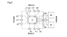
図3に示すように、各検出器31、32、33は本体20、すなわち、データ処理装置21の周囲に配置されている。図3の例では、車両前方に前方検出器31F、32F、33F、車両後方に後方検出器31B、32B、33B、車両右方に右方検出器31R、32R、33R、車両左方に左方検出器31L、32L、33Lが配置されている。データ処理装置21には、12個の検出器から12本の配線が接続されている。一方、データ処理装置21には、運転支援制御装置40からの1本の配線、並びに車両CAN55からの1本の配線が接続されている。車両CAN55は、車両50内において検出信号や制御信号を各デバイス間において通信するためのプロトコルであり、本実施形態においては、車両CAN55を通じて得られる情報の情報源として模式的に示している。車両CAN55を通じて得られる情報は、例えば、車速、ヨーレート、操舵角、方向指示器の操作といった走行情報、環境明度、天候、GNSS(全地球衛星航法システム)といった環境情報の各情報である。なお、図3においては、以降の説明を容易にするために3種類の異なる検出器31、32、33が配置される例を示しているが、1種類または2種類、さらには4種類以上の検出器が用いられても良い。
As shown in FIG. 3, each of the
図4に示すように、データ処理装置21は、統合データ生成部200、メモリ201、優先度決定部202、検出器入力部203、出力部204、情報入力部205を備えている。データ処理装置21は、FPGAやASICといった予めプログラムされた集積回路によってハードウェア的に実現されている。統合データ生成部200は、検出器31、32、33から取得した検出データを用いて車両制御装置40に対して送信すべき統合データを生成するための統合データ生成処理を実行する。優先度決定部201は、統合データを生成する際に、検出器31、32、33からの検出データのうち、優先されるべき検出データ、すなわち、時間的にまたは量的に優先すべき検出データを決定する。メモリ202は、検出器の配置位置の情報である検出器配置情報DIを不揮発的且つ読み出し専用に格納し、また、車両制御装置40に対して送信する、検出器31、32、33からの検出データの優先度を決定するための優先度決定テーブルを読み書き可能に格納していても良い。
As shown in FIG. 4, the
検出器入力部203には、複数かつ複数種類の検出器31、32、33が配線としての検出信号線を介して接続されている。検出器31、32、33からは検出データが入力される。出力部204には、運転支援制御装置40が配線としての統合データ信号線を介して接続されている。運転支援制御装置40に対しては、統合データが出力される。情報入力部205には、車両CAN55が配線を介して接続されている。車両CAN55からは走行情報や環境情報が入力される。
A plurality of and a plurality of types of
運転支援制御装置40は、図示しない運転支援装置を介して、運転者によるアクセルペダル操作に応じて、または、運転者によるアクセルペダル操作とは無関係に内燃機関やモータの出力を制御し、運転者による制動ペダル操作とは無関係に制動装置による制動を実現し、あるいは、運転者によるステアリングホイールの操作とは無関係に操舵装置による操舵を実現する。
The driving
第1の実施形態に係るデータ処理装置21により実行される統合データ生成処理について説明する。図4に示す処理ルーチンは、例えば、車両の制御システムの始動時から停止時まで、または、スタートスイッチがオンされてからスタートスイッチがオフされるまで、所定の時間間隔、例えば、数ミリ秒間隔にて繰り返して実行される。
The integrated data generation process executed by the
統合データ生成部200は、各検出器31、32、33から検出器入力部203を介して検出データを取得する(ステップS100)。優先度決定部201は、情報入力部205を介して車両CAN55から走行情報や環境情報といった各種情報、並びにメモリ202に格納されている検出器配置情報DIを取得し、各種情報を用いて優先度を決定する(ステップS102)。優先度の決定は、例えば、優先度決定部201が備える、あるいは、メモリ202に格納されている、図6に示す、検出器の配置位置と車両50の走行状態に基づく優先度決定テーブルを用いて決定される。優先度決定テーブルは車両50の走行状態に応じて動的に更新されても良い。なお、優先度が高いとは、統合データに占めるデータ量が大きいこと、すなわち、割合が高いことを意味し、優先度が低いとは、統合データに示すデータ量が小さいこと、すなわち、割合が低いことを意味し、相対的な重み付けの大小と同様に考えることができる。本実施形態においては、検出器の配置位置に応じて優先度が決定されるので、各配置位置の検出器は一群の検出器群、例えば、前方検出器31F、32F、33Fは一群の前方センサ群として扱われ、各検出器の種別は考慮されない。データ処理装置21と運転支援制御装置40との間は1本の配線で接続されており、通信帯域、すなわち、送信データ量の上限は限られている。そこで、通信帯域の上限値、すなわち送信データ量の最大値に対して割り当てるべき各検出器31、32、33からの検出データの割合、換言すれば優先度合いを決定するために優先度決定テーブルが用いられる。なお、通信帯域は、例えば、伝送率、転送速度といった用語と同様に、単位時間当たりに送信することができるデータ量を意味し、一般的に、受信側において、バッファの上書きやデータ廃棄を伴うことなく単位時間当たりに処理できるデータ量によって決定される。車両50が右折する場合には、図7に示すように、実線Phiで囲まれている前方検出器31F、32F、33Fおよび右方検出器31R、32R,33Rの優先度、すなわち、統合データに占める割合はそれぞれ30%、40%に高められ、二点鎖線Ploで囲まれている左方検出器31L、32L、33Lおよび後方検出器31B、32B、33Bの優先度はそれぞれ10%、20%に低められる。なお、優先度が割り当てられない場合には、各配置位置の検出器に対して同一の25%の割合が割り当てられる。なお、図6に示す具体的な優先度、すなわち、割り当て割合は一例に過ぎす、車両50の走行状態に応じた割り当ての傾向が維持される限り適宜決定されれば良い。また、割合は、機械学習などの結果を用いて調整されても良い。例えば、
・実際の走行シーンにおいては、例えば、対向車線と交差する旋回、左側通行における右折シーン、右側通行における左折シーンにおける右折信号や左折信号、信号のない交差点が存在し、上記例示より複雑である。そこで、学習によって現在の走行状態、他車両を始めとする対象物を含む周辺環境に応じてさらに細分化されても良い。
・例えば、急制動や急操舵といった要因に基づいて、運転者が不足する監視能力を推定、判定し、割合に対する係数や重み付けが決定され、最終的な割合に反映されてもよい。
The integrated
-In an actual driving scene, for example, there are a turn crossing an oncoming lane, a right turn scene in left-hand traffic, a right turn signal or a left turn signal in a left turn scene in right-hand traffic, and an intersection without a signal, which is more complicated than the above example. Therefore, it may be further subdivided according to the current traveling state and the surrounding environment including an object such as another vehicle by learning.
-For example, based on factors such as sudden braking and sudden steering, the driver may estimate and determine the insufficient monitoring ability, determine the coefficient and weighting for the ratio, and reflect it in the final ratio.
車両50の前進時には、前方検出器31F、32F、33Fの優先度が高められるが、後方から側方への対象物の接近の可能性も考えられるので、他の配置位置の検出器の優先度は同一とされる。車両50の左折時には前方検出器31F、32F、33F、並びに左方検出器31L、32L、33Lの優先度が高められ、車両50の後進時には、前方からの対象物の接近確率は低いので、後方検出器31B、32B、33B、右方検出器31R、32R、33R、並びに左方検出器31L、32L、33Lの優先度が高められ、前方検出器31F、32F、33Fの優先度が大きく低減される。車両50の左方への進路変更時には、左方検出器31L、32L、33L、並びに後方検出器31B、32B、33Bの優先度が高められ、右方検出器31R、32R、33Rの優先度が大きく低減される。車両50の右方への進路変更時には、右方検出器31R、32R、33R、並びに後方検出器31B、32B、33Bの優先度が高められ、左方検出器31L、32L、33Lの優先度が大きく低減される。なお、本実施形態においては、検出器群の配置位置と車両の走行状態に応じて優先度が決定されるので、少なくとも一種類の検出器が複数個、異なる配置位置に配置されていれば良く、検出器31、32、33のうち少なくともいずれか一種類の検出器が用いられる際に技術的な効果を奏する。
When the
統合データ生成部200は、決定された優先度に応じて統合データを生成する(ステップS104)。なお、優先度に応じた統合データの生成は、優先度に応じた、送信用のデータ量の決定、すなわち、総送信データ量の割当を意味し、時分割多重化方式が採用される場合には、各検出器31、32、33からの検出データの送信回数が優先度に応じて増大されることで、優先度の高い検出器からの送信データ量が増大され、送信回数が優先度に応じて減少されることで、優先度の低い検出器からの送信データ量が相対的に減少される。あるいは、各検出器31、32、33からの検出データが優先度に応じたデータ量で組み合わせられた送信用のデータフレームとして統合データが生成されてもよい。優先度が反映されることによって、例えば、図8に示すように、前方検出器31F、32F、33Fからの検出データと、右方検出器31R、32R、33Rからの検出データが示す割合が大きい統合データが生成される。図8には比較のために優先度反映前、すなわち、優先度を反映しない場合に生成される統合データにおける、各配置位置における検出器からの検出データの割合が示されている。統合データ中における割合の低減は、各検出器31、32、33から出力される検出データの容量を低減することによって実現され、例えば、検出点数の削減や解像度の低減といったデータの間引きによる容量削減、検出データの送信頻度の低減によって実現される。統合データ生成部200は、出力部204を介して、運転支援制御装置40に対して統合データを送信して(ステップS106)、本処理ルーチンは終了する。なお、統合データ生成部200による統合データの生成には、送信用のデータ量の割当に加えて、データ処理装置21と車両制御装置40との間で共通データフォーマットが用いられる場合、共通データフォーマットへのフォーマット変換、フレームレートの統合といった統合処理が含まれていても良い。
The integrated
以上説明したように第1の実施形態に係る計測装置ユニット10によれば、データ処理装置21は、複数の検出器31、32、33とそれぞれ接続されている複数の入力部203を備え、統合データ生成部200によって、複数の入力部203を介して入力される複数の検出器31、32、33からの検出データを用いて統合データを生成し、出力部204を介して車両50内の運転支援制御装置40に送信することができる。したがって、図9に示すように各検出器31、32、33が運転支援制御装置40に対して直接配線される従来の計測装置ユニットと比較して、多数の検出器を集約して計測装置ユニットとして車両に搭載する場合であっても、各検出器と車両内に備えられている運転支援制御装置との間における配線数を低減することが可能となり、配線設計を容易化できる。また、車両50の外部から車両50の内部への配線数が低減されるので、車両50の外部と内部との境界における防水箇所数を低減すること、並びに防水対策を容易化することができる。
As described above, according to the
第1の実施形態に係る計測装置ユニット10によれば、車両50の走行状態および検出器31、32、33の配置位置に応じて、統合データに割り当てられる各検出器31、32、33からのデータ量の優先度、すなわち、割当量が決定される。したがって、走行中の車両50において運転支援制御装置40によって実行される可能性の高い運転支援に関連する検出器の検出データを優先して送信することができる。この結果、優先度を考慮しない送信による通信帯域の超過に伴う必要とされるデータの欠落や送信遅延を防止または抑制することが可能となり、運転支援制御装置40による運転支援制御の精度並びに適時性が向上される。
According to the
上記説明においては、検出器31、32、33の配置位置と車両の走行状態に応じた優先度の決定について説明した。これに対して、車両50の周囲の環境情報に応じて、検出器31、32、33の種類に応じて優先度が決定されても良い。図10は、周囲環境として照度センサによって得られる車両50の周囲の明るさ環境に応じて優先度が決定される場合に生成される統合データにおける検出データの割合の一例を示す。より具体的には、カメラ31、ライダー32およびレーダ33という三種類の検出器が複数備えられる場合における優先度の割当を示す。図10において優先度反映前は、例えば、昼間時であり、優先度反映後は、例えば、夜間時である。なお、夜間時とは、照度センサによって得られる照度が予め定められた照度、例えば、100luxよりも低い値を示す環境光状態を意味する。一般的に、夜間時や暗所では、受光型(パッシブタイプ)の検出器31、すなわち、カメラの分解能は低くなるので、環境光の影響を受けにくい発光受光型(アクティブタイプ)の検出器32、すなわち、ライダーや環境光の影響を受けない検出器33、すなわち、ミリ波レーダの優先度を高める。この結果、図11に示すように、夕刻時には昼間時と比べて、統合データに占める検出器32の検出データ量が微増され、検出器31の検出データ量が微減される。夜間時には、昼間時や夕刻時と比べて、統合データに占める検出器32の検出データ量が増大され、検出器33の検出データ量が微増され、検出器31の検出データ量が低減される。検出器32および検出器33からの検出データの割合を昼間時や夕刻時よりも増大または微増させることによって、運転支援制御装置40における運転支援制御の精度、適時性の向上を図ることができる。なお、図10の例においては、検出器31、32、33の配置位置は優先度に反映されていない。また、図11において、例えば、照度1000luxは日没時程度の環境光、100luxは夜間街灯点灯時程度の環境光、1luxは夜間街灯なし程度の環境光に対応する。さらに、照度センサの出力照度値に応じて図11に示す割合の中間値が用いられても良い。
In the above description, the determination of the priority according to the arrangement position of the
さらに、図12は、周囲環境としてレインセンサによって得られる車両50の周囲の天候環境に応じて優先度が決定される場合に生成される統合データにおける検出データの割合の一例を示す。図12において優先度反映前は、例えば、晴天時であり、優先度反映後は、例えば、雨天時、霧発生時、雪天時である。なお、雨天時および雪天時とは、レインセンサによって雨滴や雪が検出される天候状態を意味する。なお、レインセンサの構成・原理は既知であるから説明を省略する。一般的に、雨天時や雪天時、さらには霧発生時には、光学式の検出器31、32の分解能は、雨滴、雪片や水蒸気による減衰の影響を受けにくい電波式の検出器33、すなわち、レーダと比べて低くなるので、レーダの優先度を高める。優先度、すなわち、統合データに占める各検出器31、32、33からのデータ量の割合の例を図13に示す。降雨量が1mm/h未満の雨天時には、雨滴により検出器31、32の検出精度は影響を受けないので晴天時と同様の割合に設定される。一方、降雨量が1mm/h以上15mm/h未満、15mm/h以上の雨天時には、晴天時と比べて、統合データに占める検出器33の検出データ量が増大され、検出器31、32の検出データ量が低減される。特に、降雨量が15mm/h以上の雨天時には、検出器33からのデータ量の割合が晴天時の4倍にまで増大される。光が乱反射し易い霧の場合には、降雨量が15mm/h以上の雨天時と同様の割合が適用され、雪天時の場合は、降雨量が1mm/h以上15mm/h未満の雨天時と同様の割合が適用される。なお、雪天時についても降雪量に応じて降雨量が15mm/h以上の雨天時と同様の割合が適用されても良い。さらに、レインセンサ等の出力値に応じて図13に示す割合の中間値が用いられても良い。非晴天時における、検出器33からの検出データの割合を晴天時よりも増大させることによって、運転支援制御装置40における運転支援制御の精度、適時性の向上を図ることができる。なお、図12の例においては、検出器31、32、33の配置位置は優先度に反映されていない。なお、霧や雪といった天候状態は、例えば、各種の路車間通信や車車間通信を通じて提供される地域的な天候情報を用いることにより取得されても良い。図14に示すように、明るさ環境と天候環境とが複合的に考慮されて、優先度、すなわち、統合データに占める各検出器31、32、33からのデータ量の割合が設定されても良い。車両50の周囲の環境情報として複数の環境を考慮することによって、運転支援制御装置40における運転支援制御の精度、適時性の更なる向上を図ることができる。
Further, FIG. 12 shows an example of the ratio of the detected data in the integrated data generated when the priority is determined according to the weather environment around the
図10〜図14の例において さらに、検出器31、32、33の配置位置が考慮されて優先度が決定されても良い。車両50の走行情報と共に環境明度や天候といった環境情報が考慮されて、検出器の配置位置および検出器の種別を用いて、統合データに占める各検出器からの検出データの優先度、すなわち、割合が決定されても良い。この場合には、車両50の走行情報および環境情報に応じた割合で各検出器からの検出データを含む統合データを生成することができるので、運転支援制御装置40における運転支援制御の精度、適時性の向上を更に図ることができる。さらに、車両50の走行持に運転支援制御装置40からの動的な要求に応じて検出器31、32、33からの検出データの優先度が決定されても良い。この場合には、運転支援制御装置40に対して、運転支援制御装置40が実行する運転支援に応じた検出データを優先して送信することができるので、運転支援制御装置40における運転支援の実行精度、適時性を更に向上させることができ、不要な検出データの送信を抑制して統合データにおける通信帯域に余裕を持たせることができる。図15を参照して、検出器31、32、33の配置位置および車両50の走行情報と共に車両50の周辺環境情報が考慮される場合に、データ処理装置21により実行される統合データ生成処理について説明する。図15に示す処理ルーチンは、例えば、車両の制御システムの始動時から停止時まで、または、スタートスイッチがオンされてからスタートスイッチがオフされるまで、所定の時間間隔、例えば、数ミリ秒間隔にて繰り返して実行される。なお、図5を用いて説明済みの処理ステップについては、簡潔な説明に止める。
Further, in the example of FIGS. 10 to 14, the priority may be determined in consideration of the arrangement positions of the
統合データ生成部200は、各検出器31、32、33から検出器入力部203を介して検出データを取得する(ステップS200)。優先度決定部201は、車両50の周辺の環境情報に対応する参照テーブルを決定する(ステップS202)。参照テーブルは、例えば、図11、図13および図14に示す参照テーブルであり、車両50が備える環境情報を取得するためのセンサ種に応じて、明るさ環境および天候環境の少なくともいずれかに対応する参照テーブルが決定され得る。図11、図13および図14に示す参照テーブルは、例えば、優先度決定部201が備えていても良く、あるいは、メモリ202に格納されていても良い。優先度決定部201は、情報入力部205を介して車両CAN55から取得した環境情報、並びに決定した参照テーブルを用いて周辺環境優先度を決定する(ステップS204)。周辺環境優先度は、照度や天候状態をパラメータとして、図10〜図13を用いて説明した決定手順によって決定される。優先度決定部201は、情報入力部205を介して車両CAN55から取得した走行情報や環境情報といった各種情報、並びにメモリ202に格納されている検出器配置情報DIを用いて走行状態優先度を決定する(ステップS206)。
The integrated
統合データ生成部200は、決定された周辺環境優先度および走行状態優先度に応じて統合データを生成する(ステップS208)。より具体的には、決定された周辺環境優先度における各検出器31、32、33に対する各割合に対して、決定された走行状態優先度における各検出器31、32、33に対する各割合を乗算することによって決定され得る。例えば、図6に示すように、右折時であれば右方検出器31R、32R、33Rからのデータ量が40%の帯域を占め、図14に示すように、車両周辺環境が晴天−昼間である場合にはカメラ31のデータ量が60%の帯域を占めるので、右方検出器としてのカメラ31Rに対して24%の帯域が割り当てられる。統合データ生成部200は、出力部204を介して、運転支援制御装置40に対して統合データを送信して(ステップS210)、本処理ルーチンは終了する。なお、本実施形態においては、右方検出器として、カメラ31R、ライダー32Rおよびレーダ33Rの各1個ずつが配置されている場合を例にとって説明しているが、例えば、2個のカメラ31R、1個のライダー32Rおよびレーダ33Rが配置されている場合には、各検出器の必要帯域を考慮した植で、帯域上限に収まるように各検出器31、32、33に対する割当が変更されても良い。
The integrated
第2の実施形態:
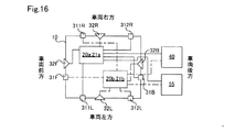
第1の実施形態に係る計測装置ユニット10は1つのデータ処理装置21を備えていたが、第2の実施形態に係る計測装置ユニット10は、図16に示すように2つの本体20a、20b内に内包されているデータ処理装置21a、21bを備えている。なお、各データ処理装置21a、21bを始めとする各装置、機器の構成・機能は、第1の実施形態において説明済みであるから、第1の実施形態において用いられている同一の符合を付すことで説明を省略する。
Second embodiment:
The measuring
図16の例では、車両50の同一方向に配置されている複数の検出器31、32、33は、それぞれ、異なるデータ処理装置21a、21bに接続されている。また、異なる種類の検出器が異なるデータ処理装置21a、21bに接続されている。したがって、データ処理装置21a、21bの何れが一方に故障や不具合が発生した場合であっても、冗長性が担保されるので、運転支援制御装置40に対して複数種類の検出データを含む統合データを送信し続けることが可能となり、車両50において自律運転を含む運転支援制御実行下における走行継続、あるいは、待避走行への移行を実行することができる。また、各データ処理装置21a、21bと運転支援制御装置40とがそれぞれ接続されるので、2倍の通信帯域を確保することが可能となり、統合データに示す各検出器31、32、33からの検出データ量をより多く統合データに割り当てることが可能となり、優先度の低い検出データの低減割合の抑制を図ることができる。例えば、カメラ31が出力する検出データ量は、ライダー32やレーダ33よりも多いが、1つのデータ処理装置21a、21bに対するカメラ31の接続数を分散させることで、統合データの通信帯域に余裕を持たせて優先度の低い検出データのデータ量の削減を抑制することができる。さらに、各検出データの最低データ量を保証しつつ、配置される検出器31、32、33の数を増大させることも可能となる。
In the example of FIG. 16, a plurality of
図16の例では、異なる種類の検出器が異なるデータ処理装置21a、21bに接続され、検出器の種別に関する冗長性が図られているが、同一種類の検出器が同一のデータ処理装置21a、21bに接続されることで、検出器の配置位置に関する冗長性を向上させても良い。さらに、車両50の各方向において同一種類の検出器を複数備え、同一種類の各検出器を異なるデータ処理装置21a、21bに接続することによって、検出器の配置位置に関する冗長性が更に向上されても良い。
In the example of FIG. 16, different types of detectors are connected to different data processing devices 21a and 21b to provide redundancy regarding the types of detectors, but the same type of detectors are the same data processing device 21a, By connecting to 21b, the redundancy regarding the arrangement position of the detector may be improved. Further, by providing a plurality of detectors of the same type in each direction of the
その他の実施形態:
(1)上記実施形態においては、計測装置ユニット10は、車両制御装置40として、車両50内の運転支援制御装置40と接続される例について説明したが、車両制御装置40は運転支援制御装置40に限られず、車両制御装置、車内ネットワークにおける通信ゲートウェイ制御装置といった種々の制御装置であっても良い。何れの場合にも、車両50の外部から車両50の内部への配線数を削減することができるという利点が得られる。
Other embodiments:
(1) In the above embodiment, an example in which the
(2)上記各実施形態においては、FPGAやASICといった予めプログラムされた集積回路によって統合データの生成処理が実現されているが、CPUが統合データ生成プログラムを実行することによって、ソフトウェア的に統合データの生成処理が実現されてもよく、またはディスクリート回路によってハードウェア的に実現されても良い。すなわち、上記各実施形態における制御部およびその手法は、コンピュータプログラムにより具体化された一つまたは複数の機能を実行するようにプログラムされたプロセッサおよびメモリを構成することによって提供された専用コンピュータにより、実現されてもよい。あるいは、本開示に記載の制御部およびその手法は、一つ以上の専用ハードウェア論理回路によってプロセッサを構成することによって提供された専用コンピュータにより、実現されてもよい。もしくは、本開示に記載の制御部およびその手法は、一つまたは複数の機能を実行するようにプログラムされたプロセッサおよびメモリと一つ以上のハードウェア論理回路によって構成されたプロセッサとの組み合わせにより構成された一つ以上の専用コンピュータにより、実現されてもよい。また、コンピュータプログラムは、コンピュータにより実行されるインストラクションとして、コンピュータ読み取り可能な非遷移有形記録媒体に記憶されていてもよい。 (2) In each of the above embodiments, the integrated data generation process is realized by a pre-programmed integrated circuit such as FPGA or ASIC. However, when the CPU executes the integrated data generation program, the integrated data is software-wise. The generation process may be realized, or it may be realized in hardware by a discrete circuit. That is, the control unit and its method in each of the above embodiments are provided by a dedicated computer provided by configuring a processor and memory programmed to perform one or more functions embodied by a computer program. It may be realized. Alternatively, the controls and methods thereof described in the present disclosure may be implemented by a dedicated computer provided by configuring the processor with one or more dedicated hardware logic circuits. Alternatively, the controls and methods thereof described in the present disclosure consist of a combination of a processor and memory programmed to perform one or more functions and a processor composed of one or more hardware logic circuits. It may be realized by one or more dedicated computers. Further, the computer program may be stored in a computer-readable non-transitional tangible recording medium as an instruction executed by the computer.
以上、実施形態、変形例に基づき本開示について説明してきたが、上記した発明の実施の形態は、本開示の理解を容易にするためのものであり、本開示を限定するものではない。本開示は、その趣旨並びに特許請求の範囲を逸脱することなく、変更、改良され得ると共に、本開示にはその等価物が含まれる。たとえば、発明の概要の欄に記載した各形態中の技術的特徴に対応する実施形態、変形例中の技術的特徴は、上述の課題の一部又は全部を解決するために、あるいは、上述の効果の一部又は全部を達成するために、適宜、差し替えや、組み合わせを行うことが可能である。また、その技術的特徴が本明細書中に必須なものとして説明されていなければ、適宜、削除することが可能である。 Although the present disclosure has been described above based on the embodiments and modifications, the above-described embodiments of the present invention are for facilitating the understanding of the present disclosure and do not limit the present disclosure. The present disclosure may be modified or improved without departing from its spirit and claims, and the present disclosure includes its equivalents. For example, the embodiments corresponding to the technical features in each of the embodiments described in the column of the outline of the invention, the technical features in the modifications may be used to solve some or all of the above-mentioned problems, or as described above. It is possible to replace or combine them as appropriate to achieve some or all of the effects. Further, if the technical feature is not described as essential in the present specification, it can be deleted as appropriate.
10…計測装置ユニット、20…本体、21…データ処理装置、201…統合データ生成部、31…検出器(カメラ)、32…検出器(ライダー)、33…検出器(レーダ)、40…運転支援制御装置、50…車両。 10 ... Measuring device unit, 20 ... Main body, 21 ... Data processing device, 201 ... Integrated data generator, 31 ... Detector (camera), 32 ... Detector (rider), 33 ... Detector (radar), 40 ... Operation Assistance control device, 50 ... vehicle.
Claims (10)
複数の検出器(31、32、33)と、
前記複数の検出器とそれぞれ接続されている複数の入力部(203)と、車両内に配置されている制御装置(40)と接続されている出力部(204)と、前記複数の入力部を介して入力される前記複数の検出器からの検出データを用いて統合データを生成して前記出力部を介して出力する統合データ生成部(200)と、を備えるデータ処理装置(21)と、を備える車載用の計測装置ユニット。 An in-vehicle measuring device unit (10)
With multiple detectors (31, 32, 33),
A plurality of input units (203) connected to the plurality of detectors, an output unit (204) connected to a control device (40) arranged in the vehicle, and the plurality of input units. A data processing device (21) including an integrated data generation unit (200) that generates integrated data using detection data from the plurality of detectors input via the output unit and outputs the integrated data via the output unit. In-vehicle measuring device unit equipped with.
前記複数の検出器は、異なる種類の複数の検出器を含む、車載用の計測装置ユニット。 In the vehicle-mounted measuring device unit according to claim 1,
The plurality of detectors are an in-vehicle measuring device unit including a plurality of detectors of different types.
前記データ処理装置を内包する本体(20)を備え、
前記複数の検出器は前記本体の周囲に配置されている、車載用の計測装置ユニット。 The vehicle-mounted measuring device unit according to claim 1 or 2 further comprises.
A main body (20) including the data processing device is provided.
The plurality of detectors are an in-vehicle measuring device unit arranged around the main body.
前記データ処理装置は、車両の環境情報、車両の走行情報および前記複数の検出器の配置情報の少なくともいずれか一つの情報を用いて、各前記検出器からの検出データに対する優先度を決定し、決定した優先度に応じて前記統合データを生成する、車載用の計測装置ユニット。 In the vehicle-mounted measuring device unit according to any one of claims 1 to 3.
The data processing device determines the priority for the detection data from each of the detectors by using at least one of the vehicle environment information, the vehicle traveling information, and the arrangement information of the plurality of detectors. An in-vehicle measuring device unit that generates the integrated data according to a determined priority.
前記データ処理装置は、前記統合データに占める、前記優先度の高い検出データの量を他の前記検出データの量よりも大きくする、車載用の計測装置ユニット。 In the vehicle-mounted measuring device unit according to claim 4,
The data processing device is an in-vehicle measuring device unit that increases the amount of high-priority detection data in the integrated data to be larger than the amount of other detection data.
前記データ処理装置は、前記優先度の高い検出データを他の前記検出データよりも高い頻度で前記統合データとして出力する、車載用の計測装置ユニット。 In the vehicle-mounted measuring device unit according to claim 4,
The data processing device is an in-vehicle measuring device unit that outputs the high-priority detection data as the integrated data at a higher frequency than the other detection data.
前記統合データ生成部は、前記車両の走行情報および前記複数の検出器の配置情報を用いて前記優先度を決定する、車載用の計測装置ユニット。 In the vehicle-mounted measuring device unit according to any one of claims 4 to 6.
The integrated data generation unit is an in-vehicle measuring device unit that determines the priority using the traveling information of the vehicle and the arrangement information of the plurality of detectors.
前記統合データ生成部は、前記車両の環境情報を用いて前記各検出器からの検出データの種別に応じて前記優先度を決定する、車載用の計測装置ユニット。 In the vehicle-mounted measuring device unit according to any one of claims 4 to 6.
The integrated data generation unit is an in-vehicle measuring device unit that determines the priority according to the type of detection data from each detector using the environmental information of the vehicle.
前記統合データ生成部は、前記制御装置において動的に要求される前記各検出器からの検出データに応じて前記優先度を決定する、車載用の計測装置ユニット。 In the vehicle-mounted measuring device unit according to any one of claims 4 to 6.
The integrated data generation unit is an in-vehicle measuring device unit that determines the priority according to the detection data from each of the detectors dynamically requested by the control device.
複数の検出器から検出データを受信し、
複数の前記検出データを用いて統合データを生成し、
車両内に配置されている制御装置(40)に対して送信すること、を備える統合データ生成方法。 This is an integrated data generation method in the in-vehicle measuring device unit (10).
Receive detection data from multiple detectors
Integrated data is generated using the plurality of the detected data,
An integrated data generation method comprising transmitting to a control device (40) arranged in a vehicle.
Priority Applications (4)
| Application Number | Priority Date | Filing Date | Title |
|---|---|---|---|
| JP2019207578A JP2021081886A (en) | 2019-11-18 | 2019-11-18 | On-vehicle measurement device unit and integrated data generation method in on-vehicle measurement device unit |
| PCT/JP2020/040239 WO2021100418A1 (en) | 2019-11-18 | 2020-10-27 | In-vehicle measurement device unit and integrated data generation method in in-vehicle measurement device unit |
| CN202080080033.5A CN114730519A (en) | 2019-11-18 | 2020-10-27 | Vehicle-mounted measuring device unit and method for generating integrated data in vehicle-mounted measuring device unit |
| US17/663,474 US20220274606A1 (en) | 2019-11-18 | 2022-05-16 | Vehicle measuring device unit and method of generating integrated data in vehicle measuring device unit |
Applications Claiming Priority (1)
| Application Number | Priority Date | Filing Date | Title |
|---|---|---|---|
| JP2019207578A JP2021081886A (en) | 2019-11-18 | 2019-11-18 | On-vehicle measurement device unit and integrated data generation method in on-vehicle measurement device unit |
Publications (2)
| Publication Number | Publication Date |
|---|---|
| JP2021081886A true JP2021081886A (en) | 2021-05-27 |
| JP2021081886A5 JP2021081886A5 (en) | 2021-10-28 |
Family
ID=75965174
Family Applications (1)
| Application Number | Title | Priority Date | Filing Date |
|---|---|---|---|
| JP2019207578A Pending JP2021081886A (en) | 2019-11-18 | 2019-11-18 | On-vehicle measurement device unit and integrated data generation method in on-vehicle measurement device unit |
Country Status (4)
| Country | Link |
|---|---|
| US (1) | US20220274606A1 (en) |
| JP (1) | JP2021081886A (en) |
| CN (1) | CN114730519A (en) |
| WO (1) | WO2021100418A1 (en) |
Families Citing this family (1)
| Publication number | Priority date | Publication date | Assignee | Title |
|---|---|---|---|---|
| JP7382791B2 (en) * | 2019-10-30 | 2023-11-17 | 株式会社日立製作所 | Abnormality determination device, vehicle support system |
Citations (10)
| Publication number | Priority date | Publication date | Assignee | Title |
|---|---|---|---|---|
| JPH04260834A (en) * | 1991-02-14 | 1992-09-16 | Nissan Motor Co Ltd | Failure judging device for vehicle system |
| JP2008205594A (en) * | 2007-02-16 | 2008-09-04 | Auto Network Gijutsu Kenkyusho:Kk | On-vehicle video communication system |
| JP2008207627A (en) * | 2007-02-23 | 2008-09-11 | Auto Network Gijutsu Kenkyusho:Kk | In-vehicle imaging system, imaging device, and display control device |
| JP2012245812A (en) * | 2011-05-25 | 2012-12-13 | Denso Corp | Communication device for vehicle |
| JP2014211742A (en) * | 2013-04-18 | 2014-11-13 | 株式会社デンソー | Control system |
| JP2017058385A (en) * | 2015-09-14 | 2017-03-23 | 新明工業株式会社 | Driving situation confirmation system, vehicle state communication device, and vehicle communication program |
| US20180113209A1 (en) * | 2016-10-21 | 2018-04-26 | Waymo Llc | Radar generated occupancy grid for autonomous vehicle perception and planning |
| WO2018175808A1 (en) * | 2017-03-23 | 2018-09-27 | Uber Technologies, Inc. | Dynamic sensor selection for self-driving vehicles |
| US20190049958A1 (en) * | 2017-08-08 | 2019-02-14 | Nio Usa, Inc. | Method and system for multiple sensor correlation diagnostic and sensor fusion/dnn monitor for autonomous driving application |
| WO2019043855A1 (en) * | 2017-08-31 | 2019-03-07 | 三菱電機株式会社 | Data transmission device, data processing system, and data transmission method |
Family Cites Families (4)
| Publication number | Priority date | Publication date | Assignee | Title |
|---|---|---|---|---|
| JP2006024103A (en) * | 2004-07-09 | 2006-01-26 | Honda Motor Co Ltd | Device for supporting vehicle driving |
| CA2583057A1 (en) * | 2006-03-31 | 2007-09-30 | Itron, Inc. | Integrated data collection, anomaly detection and investigation, such as integrated mobile utility meter reading, theft detection and investigation system |
| US9720072B2 (en) * | 2014-08-28 | 2017-08-01 | Waymo Llc | Methods and systems for vehicle radar coordination and interference reduction |
| JP2019122005A (en) * | 2018-01-11 | 2019-07-22 | アンリツ株式会社 | Bit error rate measurement device and bit error rate measurement method |
-
2019
- 2019-11-18 JP JP2019207578A patent/JP2021081886A/en active Pending
-
2020
- 2020-10-27 CN CN202080080033.5A patent/CN114730519A/en active Pending
- 2020-10-27 WO PCT/JP2020/040239 patent/WO2021100418A1/en active Application Filing
-
2022
- 2022-05-16 US US17/663,474 patent/US20220274606A1/en active Pending
Patent Citations (10)
| Publication number | Priority date | Publication date | Assignee | Title |
|---|---|---|---|---|
| JPH04260834A (en) * | 1991-02-14 | 1992-09-16 | Nissan Motor Co Ltd | Failure judging device for vehicle system |
| JP2008205594A (en) * | 2007-02-16 | 2008-09-04 | Auto Network Gijutsu Kenkyusho:Kk | On-vehicle video communication system |
| JP2008207627A (en) * | 2007-02-23 | 2008-09-11 | Auto Network Gijutsu Kenkyusho:Kk | In-vehicle imaging system, imaging device, and display control device |
| JP2012245812A (en) * | 2011-05-25 | 2012-12-13 | Denso Corp | Communication device for vehicle |
| JP2014211742A (en) * | 2013-04-18 | 2014-11-13 | 株式会社デンソー | Control system |
| JP2017058385A (en) * | 2015-09-14 | 2017-03-23 | 新明工業株式会社 | Driving situation confirmation system, vehicle state communication device, and vehicle communication program |
| US20180113209A1 (en) * | 2016-10-21 | 2018-04-26 | Waymo Llc | Radar generated occupancy grid for autonomous vehicle perception and planning |
| WO2018175808A1 (en) * | 2017-03-23 | 2018-09-27 | Uber Technologies, Inc. | Dynamic sensor selection for self-driving vehicles |
| US20190049958A1 (en) * | 2017-08-08 | 2019-02-14 | Nio Usa, Inc. | Method and system for multiple sensor correlation diagnostic and sensor fusion/dnn monitor for autonomous driving application |
| WO2019043855A1 (en) * | 2017-08-31 | 2019-03-07 | 三菱電機株式会社 | Data transmission device, data processing system, and data transmission method |
Also Published As
| Publication number | Publication date |
|---|---|
| CN114730519A (en) | 2022-07-08 |
| US20220274606A1 (en) | 2022-09-01 |
| WO2021100418A1 (en) | 2021-05-27 |
Similar Documents
| Publication | Publication Date | Title |
|---|---|---|
| US20210024084A1 (en) | Path providing device and path providing method thereof | |
| US10093224B2 (en) | Lighting apparatus for vehicle and vehicle having the same | |
| US20210403015A1 (en) | Vehicle lighting system, vehicle system, and vehicle | |
| TWI814804B (en) | Distance measurement processing apparatus, distance measurement module, distance measurement processing method, and program | |
| US11327485B2 (en) | Control device for vehicle, and vehicle | |
| WO2018139212A1 (en) | Operation control system and operation control method | |
| JP7314798B2 (en) | IMAGING DEVICE, IMAGE PROCESSING DEVICE, AND IMAGE PROCESSING METHOD | |
| US10875452B2 (en) | Driving assistance device and driving assistance method | |
| US11507789B2 (en) | Electronic device for vehicle and method of operating electronic device for vehicle | |
| US11397248B2 (en) | Sensing system and driving support system | |
| US20200126325A1 (en) | Electronic control unit and communication device | |
| US11814081B2 (en) | Control system, control method, vehicle, and computer-readable storage medium | |
| EP3838699A1 (en) | Vehicle and method for controlling body thereof | |
| US11675355B2 (en) | Path providing device and path providing method thereof | |
| US20230147535A1 (en) | Vehicle position estimation device and traveling control device | |
| JP7187291B2 (en) | Infrared camera system and vehicle | |
| JP6699344B2 (en) | Reverse vehicle detection device, reverse vehicle detection method | |
| WO2021100418A1 (en) | In-vehicle measurement device unit and integrated data generation method in in-vehicle measurement device unit | |
| JP7375678B2 (en) | Vehicle control method, vehicle control program, and vehicle control system | |
| CN111862226B (en) | Hardware design for camera calibration and image preprocessing in a vehicle | |
| US11414098B2 (en) | Control authority transfer apparatus and method of autonomous vehicle | |
| WO2022153896A1 (en) | Imaging device, image processing method, and image processing program | |
| JP2020069969A (en) | Vehicle control system | |
| US11741718B2 (en) | Light interference detection during vehicle navigation | |
| US20210258750A1 (en) | Communication control device, communication device, communication system, radio base station, communication control method, and storage medium |
Legal Events
| Date | Code | Title | Description |
|---|---|---|---|
| A521 | Request for written amendment filed |
Free format text: JAPANESE INTERMEDIATE CODE: A523 Effective date: 20210914 |
|
| A621 | Written request for application examination |
Free format text: JAPANESE INTERMEDIATE CODE: A621 Effective date: 20210914 |
|
| A131 | Notification of reasons for refusal |
Free format text: JAPANESE INTERMEDIATE CODE: A131 Effective date: 20220927 |
|
| A521 | Request for written amendment filed |
Free format text: JAPANESE INTERMEDIATE CODE: A523 Effective date: 20221028 |
|
| A131 | Notification of reasons for refusal |
Free format text: JAPANESE INTERMEDIATE CODE: A131 Effective date: 20230124 |
|
| A521 | Request for written amendment filed |
Free format text: JAPANESE INTERMEDIATE CODE: A523 Effective date: 20230313 |
|
| A02 | Decision of refusal |
Free format text: JAPANESE INTERMEDIATE CODE: A02 Effective date: 20230509 |