JP2021066955A - Alloy support - Google Patents
Alloy support Download PDFInfo
- Publication number
- JP2021066955A JP2021066955A JP2020173231A JP2020173231A JP2021066955A JP 2021066955 A JP2021066955 A JP 2021066955A JP 2020173231 A JP2020173231 A JP 2020173231A JP 2020173231 A JP2020173231 A JP 2020173231A JP 2021066955 A JP2021066955 A JP 2021066955A
- Authority
- JP
- Japan
- Prior art keywords
- printing
- droplet
- columns
- droplets
- Prior art date
- Legal status (The legal status is an assumption and is not a legal conclusion. Google has not performed a legal analysis and makes no representation as to the accuracy of the status listed.)
- Pending
Links
- 239000000956 alloy Substances 0.000 title 1
- 229910045601 alloy Inorganic materials 0.000 title 1
- 238000000034 method Methods 0.000 claims abstract description 88
- 239000000463 material Substances 0.000 claims abstract description 61
- 238000007639 printing Methods 0.000 claims description 163
- 239000000758 substrate Substances 0.000 claims description 36
- 230000015572 biosynthetic process Effects 0.000 claims description 15
- 229910052751 metal Inorganic materials 0.000 claims description 7
- 239000002184 metal Substances 0.000 claims description 7
- 238000007599 discharging Methods 0.000 claims description 5
- RYGMFSIKBFXOCR-UHFFFAOYSA-N Copper Chemical compound [Cu] RYGMFSIKBFXOCR-UHFFFAOYSA-N 0.000 claims description 4
- ATJFFYVFTNAWJD-UHFFFAOYSA-N Tin Chemical compound [Sn] ATJFFYVFTNAWJD-UHFFFAOYSA-N 0.000 claims description 4
- RTAQQCXQSZGOHL-UHFFFAOYSA-N Titanium Chemical compound [Ti] RTAQQCXQSZGOHL-UHFFFAOYSA-N 0.000 claims description 4
- 229910052782 aluminium Inorganic materials 0.000 claims description 4
- XAGFODPZIPBFFR-UHFFFAOYSA-N aluminium Chemical compound [Al] XAGFODPZIPBFFR-UHFFFAOYSA-N 0.000 claims description 4
- 229910052802 copper Inorganic materials 0.000 claims description 4
- 239000010949 copper Substances 0.000 claims description 4
- 239000010936 titanium Substances 0.000 claims description 4
- 229910052719 titanium Inorganic materials 0.000 claims description 4
- 229910001338 liquidmetal Inorganic materials 0.000 claims description 3
- 238000000151 deposition Methods 0.000 claims 2
- 230000008021 deposition Effects 0.000 claims 1
- 238000012545 processing Methods 0.000 abstract description 5
- 238000004519 manufacturing process Methods 0.000 abstract description 4
- 238000010146 3D printing Methods 0.000 description 4
- 239000000843 powder Substances 0.000 description 4
- 238000000576 coating method Methods 0.000 description 3
- 238000010586 diagram Methods 0.000 description 3
- 239000007788 liquid Substances 0.000 description 3
- 230000008018 melting Effects 0.000 description 3
- 238000002844 melting Methods 0.000 description 3
- 229910001092 metal group alloy Inorganic materials 0.000 description 3
- 229920000642 polymer Polymers 0.000 description 3
- 238000000926 separation method Methods 0.000 description 3
- XEEYBQQBJWHFJM-UHFFFAOYSA-N Iron Chemical compound [Fe] XEEYBQQBJWHFJM-UHFFFAOYSA-N 0.000 description 2
- PXHVJJICTQNCMI-UHFFFAOYSA-N Nickel Chemical compound [Ni] PXHVJJICTQNCMI-UHFFFAOYSA-N 0.000 description 2
- 239000011248 coating agent Substances 0.000 description 2
- 238000013461 design Methods 0.000 description 2
- 238000005530 etching Methods 0.000 description 2
- 239000000203 mixture Substances 0.000 description 2
- 238000012986 modification Methods 0.000 description 2
- 230000004048 modification Effects 0.000 description 2
- 239000004033 plastic Substances 0.000 description 2
- 230000003014 reinforcing effect Effects 0.000 description 2
- 239000007787 solid Substances 0.000 description 2
- 229910000906 Bronze Inorganic materials 0.000 description 1
- VYZAMTAEIAYCRO-UHFFFAOYSA-N Chromium Chemical compound [Cr] VYZAMTAEIAYCRO-UHFFFAOYSA-N 0.000 description 1
- 229910000599 Cr alloy Inorganic materials 0.000 description 1
- 229910000990 Ni alloy Inorganic materials 0.000 description 1
- 239000004677 Nylon Substances 0.000 description 1
- 229910000831 Steel Inorganic materials 0.000 description 1
- 230000009286 beneficial effect Effects 0.000 description 1
- 239000010974 bronze Substances 0.000 description 1
- 238000003486 chemical etching Methods 0.000 description 1
- 239000011651 chromium Substances 0.000 description 1
- 238000001816 cooling Methods 0.000 description 1
- KUNSUQLRTQLHQQ-UHFFFAOYSA-N copper tin Chemical compound [Cu].[Sn] KUNSUQLRTQLHQQ-UHFFFAOYSA-N 0.000 description 1
- 238000001035 drying Methods 0.000 description 1
- 230000005489 elastic deformation Effects 0.000 description 1
- 238000011049 filling Methods 0.000 description 1
- 230000008014 freezing Effects 0.000 description 1
- 238000007710 freezing Methods 0.000 description 1
- 230000012447 hatching Effects 0.000 description 1
- 238000010438 heat treatment Methods 0.000 description 1
- 229910001026 inconel Inorganic materials 0.000 description 1
- 229910052742 iron Inorganic materials 0.000 description 1
- 238000003475 lamination Methods 0.000 description 1
- 239000011344 liquid material Substances 0.000 description 1
- 238000005259 measurement Methods 0.000 description 1
- 150000002739 metals Chemical class 0.000 description 1
- 229920001778 nylon Polymers 0.000 description 1
- 238000007747 plating Methods 0.000 description 1
- 239000002861 polymer material Substances 0.000 description 1
- 229920005989 resin Polymers 0.000 description 1
- 239000011347 resin Substances 0.000 description 1
- 238000005245 sintering Methods 0.000 description 1
- 238000007711 solidification Methods 0.000 description 1
- 230000008023 solidification Effects 0.000 description 1
- 239000010935 stainless steel Substances 0.000 description 1
- 229910001256 stainless steel alloy Inorganic materials 0.000 description 1
- 239000010959 steel Substances 0.000 description 1
- 238000005496 tempering Methods 0.000 description 1
- 238000012360 testing method Methods 0.000 description 1
- 229910052727 yttrium Inorganic materials 0.000 description 1
Images


Classifications
-
- B—PERFORMING OPERATIONS; TRANSPORTING
- B22—CASTING; POWDER METALLURGY
- B22D—CASTING OF METALS; CASTING OF OTHER SUBSTANCES BY THE SAME PROCESSES OR DEVICES
- B22D23/00—Casting processes not provided for in groups B22D1/00 - B22D21/00
- B22D23/003—Moulding by spraying metal on a surface
-
- B—PERFORMING OPERATIONS; TRANSPORTING
- B22—CASTING; POWDER METALLURGY
- B22F—WORKING METALLIC POWDER; MANUFACTURE OF ARTICLES FROM METALLIC POWDER; MAKING METALLIC POWDER; APPARATUS OR DEVICES SPECIALLY ADAPTED FOR METALLIC POWDER
- B22F10/00—Additive manufacturing of workpieces or articles from metallic powder
- B22F10/10—Formation of a green body
-
- B—PERFORMING OPERATIONS; TRANSPORTING
- B22—CASTING; POWDER METALLURGY
- B22F—WORKING METALLIC POWDER; MANUFACTURE OF ARTICLES FROM METALLIC POWDER; MAKING METALLIC POWDER; APPARATUS OR DEVICES SPECIALLY ADAPTED FOR METALLIC POWDER
- B22F10/00—Additive manufacturing of workpieces or articles from metallic powder
- B22F10/20—Direct sintering or melting
- B22F10/22—Direct deposition of molten metal
-
- B—PERFORMING OPERATIONS; TRANSPORTING
- B22—CASTING; POWDER METALLURGY
- B22F—WORKING METALLIC POWDER; MANUFACTURE OF ARTICLES FROM METALLIC POWDER; MAKING METALLIC POWDER; APPARATUS OR DEVICES SPECIALLY ADAPTED FOR METALLIC POWDER
- B22F10/00—Additive manufacturing of workpieces or articles from metallic powder
- B22F10/20—Direct sintering or melting
- B22F10/25—Direct deposition of metal particles, e.g. direct metal deposition [DMD] or laser engineered net shaping [LENS]
-
- B—PERFORMING OPERATIONS; TRANSPORTING
- B22—CASTING; POWDER METALLURGY
- B22F—WORKING METALLIC POWDER; MANUFACTURE OF ARTICLES FROM METALLIC POWDER; MAKING METALLIC POWDER; APPARATUS OR DEVICES SPECIALLY ADAPTED FOR METALLIC POWDER
- B22F10/00—Additive manufacturing of workpieces or articles from metallic powder
- B22F10/40—Structures for supporting workpieces or articles during manufacture and removed afterwards
-
- B—PERFORMING OPERATIONS; TRANSPORTING
- B22—CASTING; POWDER METALLURGY
- B22F—WORKING METALLIC POWDER; MANUFACTURE OF ARTICLES FROM METALLIC POWDER; MAKING METALLIC POWDER; APPARATUS OR DEVICES SPECIALLY ADAPTED FOR METALLIC POWDER
- B22F3/00—Manufacture of workpieces or articles from metallic powder characterised by the manner of compacting or sintering; Apparatus specially adapted therefor ; Presses and furnaces
- B22F3/115—Manufacture of workpieces or articles from metallic powder characterised by the manner of compacting or sintering; Apparatus specially adapted therefor ; Presses and furnaces by spraying molten metal, i.e. spray sintering, spray casting
-
- B—PERFORMING OPERATIONS; TRANSPORTING
- B22—CASTING; POWDER METALLURGY
- B22F—WORKING METALLIC POWDER; MANUFACTURE OF ARTICLES FROM METALLIC POWDER; MAKING METALLIC POWDER; APPARATUS OR DEVICES SPECIALLY ADAPTED FOR METALLIC POWDER
- B22F3/00—Manufacture of workpieces or articles from metallic powder characterised by the manner of compacting or sintering; Apparatus specially adapted therefor ; Presses and furnaces
- B22F3/24—After-treatment of workpieces or articles
-
- B—PERFORMING OPERATIONS; TRANSPORTING
- B29—WORKING OF PLASTICS; WORKING OF SUBSTANCES IN A PLASTIC STATE IN GENERAL
- B29C—SHAPING OR JOINING OF PLASTICS; SHAPING OF MATERIAL IN A PLASTIC STATE, NOT OTHERWISE PROVIDED FOR; AFTER-TREATMENT OF THE SHAPED PRODUCTS, e.g. REPAIRING
- B29C64/00—Additive manufacturing, i.e. manufacturing of three-dimensional [3D] objects by additive deposition, additive agglomeration or additive layering, e.g. by 3D printing, stereolithography or selective laser sintering
- B29C64/10—Processes of additive manufacturing
- B29C64/106—Processes of additive manufacturing using only liquids or viscous materials, e.g. depositing a continuous bead of viscous material
- B29C64/112—Processes of additive manufacturing using only liquids or viscous materials, e.g. depositing a continuous bead of viscous material using individual droplets, e.g. from jetting heads
-
- B—PERFORMING OPERATIONS; TRANSPORTING
- B29—WORKING OF PLASTICS; WORKING OF SUBSTANCES IN A PLASTIC STATE IN GENERAL
- B29C—SHAPING OR JOINING OF PLASTICS; SHAPING OF MATERIAL IN A PLASTIC STATE, NOT OTHERWISE PROVIDED FOR; AFTER-TREATMENT OF THE SHAPED PRODUCTS, e.g. REPAIRING
- B29C64/00—Additive manufacturing, i.e. manufacturing of three-dimensional [3D] objects by additive deposition, additive agglomeration or additive layering, e.g. by 3D printing, stereolithography or selective laser sintering
- B29C64/40—Structures for supporting 3D objects during manufacture and intended to be sacrificed after completion thereof
-
- B—PERFORMING OPERATIONS; TRANSPORTING
- B33—ADDITIVE MANUFACTURING TECHNOLOGY
- B33Y—ADDITIVE MANUFACTURING, i.e. MANUFACTURING OF THREE-DIMENSIONAL [3-D] OBJECTS BY ADDITIVE DEPOSITION, ADDITIVE AGGLOMERATION OR ADDITIVE LAYERING, e.g. BY 3-D PRINTING, STEREOLITHOGRAPHY OR SELECTIVE LASER SINTERING
- B33Y10/00—Processes of additive manufacturing
-
- B—PERFORMING OPERATIONS; TRANSPORTING
- B33—ADDITIVE MANUFACTURING TECHNOLOGY
- B33Y—ADDITIVE MANUFACTURING, i.e. MANUFACTURING OF THREE-DIMENSIONAL [3-D] OBJECTS BY ADDITIVE DEPOSITION, ADDITIVE AGGLOMERATION OR ADDITIVE LAYERING, e.g. BY 3-D PRINTING, STEREOLITHOGRAPHY OR SELECTIVE LASER SINTERING
- B33Y30/00—Apparatus for additive manufacturing; Details thereof or accessories therefor
-
- B—PERFORMING OPERATIONS; TRANSPORTING
- B33—ADDITIVE MANUFACTURING TECHNOLOGY
- B33Y—ADDITIVE MANUFACTURING, i.e. MANUFACTURING OF THREE-DIMENSIONAL [3-D] OBJECTS BY ADDITIVE DEPOSITION, ADDITIVE AGGLOMERATION OR ADDITIVE LAYERING, e.g. BY 3-D PRINTING, STEREOLITHOGRAPHY OR SELECTIVE LASER SINTERING
- B33Y40/00—Auxiliary operations or equipment, e.g. for material handling
- B33Y40/20—Post-treatment, e.g. curing, coating or polishing
-
- B—PERFORMING OPERATIONS; TRANSPORTING
- B33—ADDITIVE MANUFACTURING TECHNOLOGY
- B33Y—ADDITIVE MANUFACTURING, i.e. MANUFACTURING OF THREE-DIMENSIONAL [3-D] OBJECTS BY ADDITIVE DEPOSITION, ADDITIVE AGGLOMERATION OR ADDITIVE LAYERING, e.g. BY 3-D PRINTING, STEREOLITHOGRAPHY OR SELECTIVE LASER SINTERING
- B33Y50/00—Data acquisition or data processing for additive manufacturing
- B33Y50/02—Data acquisition or data processing for additive manufacturing for controlling or regulating additive manufacturing processes
-
- B—PERFORMING OPERATIONS; TRANSPORTING
- B33—ADDITIVE MANUFACTURING TECHNOLOGY
- B33Y—ADDITIVE MANUFACTURING, i.e. MANUFACTURING OF THREE-DIMENSIONAL [3-D] OBJECTS BY ADDITIVE DEPOSITION, ADDITIVE AGGLOMERATION OR ADDITIVE LAYERING, e.g. BY 3-D PRINTING, STEREOLITHOGRAPHY OR SELECTIVE LASER SINTERING
- B33Y70/00—Materials specially adapted for additive manufacturing
- B33Y70/10—Composites of different types of material, e.g. mixtures of ceramics and polymers or mixtures of metals and biomaterials
-
- B—PERFORMING OPERATIONS; TRANSPORTING
- B33—ADDITIVE MANUFACTURING TECHNOLOGY
- B33Y—ADDITIVE MANUFACTURING, i.e. MANUFACTURING OF THREE-DIMENSIONAL [3-D] OBJECTS BY ADDITIVE DEPOSITION, ADDITIVE AGGLOMERATION OR ADDITIVE LAYERING, e.g. BY 3-D PRINTING, STEREOLITHOGRAPHY OR SELECTIVE LASER SINTERING
- B33Y80/00—Products made by additive manufacturing
-
- B—PERFORMING OPERATIONS; TRANSPORTING
- B81—MICROSTRUCTURAL TECHNOLOGY
- B81C—PROCESSES OR APPARATUS SPECIALLY ADAPTED FOR THE MANUFACTURE OR TREATMENT OF MICROSTRUCTURAL DEVICES OR SYSTEMS
- B81C1/00—Manufacture or treatment of devices or systems in or on a substrate
- B81C1/00015—Manufacture or treatment of devices or systems in or on a substrate for manufacturing microsystems
- B81C1/00023—Manufacture or treatment of devices or systems in or on a substrate for manufacturing microsystems without movable or flexible elements
- B81C1/00111—Tips, pillars, i.e. raised structures
-
- B—PERFORMING OPERATIONS; TRANSPORTING
- B22—CASTING; POWDER METALLURGY
- B22F—WORKING METALLIC POWDER; MANUFACTURE OF ARTICLES FROM METALLIC POWDER; MAKING METALLIC POWDER; APPARATUS OR DEVICES SPECIALLY ADAPTED FOR METALLIC POWDER
- B22F10/00—Additive manufacturing of workpieces or articles from metallic powder
- B22F10/40—Structures for supporting workpieces or articles during manufacture and removed afterwards
- B22F10/43—Structures for supporting workpieces or articles during manufacture and removed afterwards characterised by material
-
- B—PERFORMING OPERATIONS; TRANSPORTING
- B22—CASTING; POWDER METALLURGY
- B22F—WORKING METALLIC POWDER; MANUFACTURE OF ARTICLES FROM METALLIC POWDER; MAKING METALLIC POWDER; APPARATUS OR DEVICES SPECIALLY ADAPTED FOR METALLIC POWDER
- B22F10/00—Additive manufacturing of workpieces or articles from metallic powder
- B22F10/40—Structures for supporting workpieces or articles during manufacture and removed afterwards
- B22F10/47—Structures for supporting workpieces or articles during manufacture and removed afterwards characterised by structural features
-
- B—PERFORMING OPERATIONS; TRANSPORTING
- B22—CASTING; POWDER METALLURGY
- B22F—WORKING METALLIC POWDER; MANUFACTURE OF ARTICLES FROM METALLIC POWDER; MAKING METALLIC POWDER; APPARATUS OR DEVICES SPECIALLY ADAPTED FOR METALLIC POWDER
- B22F2999/00—Aspects linked to processes or compositions used in powder metallurgy
-
- B—PERFORMING OPERATIONS; TRANSPORTING
- B81—MICROSTRUCTURAL TECHNOLOGY
- B81C—PROCESSES OR APPARATUS SPECIALLY ADAPTED FOR THE MANUFACTURE OR TREATMENT OF MICROSTRUCTURAL DEVICES OR SYSTEMS
- B81C2201/00—Manufacture or treatment of microstructural devices or systems
- B81C2201/01—Manufacture or treatment of microstructural devices or systems in or on a substrate
- B81C2201/0174—Manufacture or treatment of microstructural devices or systems in or on a substrate for making multi-layered devices, film deposition or growing
- B81C2201/0183—Selective deposition
- B81C2201/0184—Digital lithography, e.g. using an inkjet print-head
-
- C—CHEMISTRY; METALLURGY
- C22—METALLURGY; FERROUS OR NON-FERROUS ALLOYS; TREATMENT OF ALLOYS OR NON-FERROUS METALS
- C22C—ALLOYS
- C22C1/00—Making non-ferrous alloys
- C22C1/04—Making non-ferrous alloys by powder metallurgy
- C22C1/0408—Light metal alloys
- C22C1/0416—Aluminium-based alloys
-
- C—CHEMISTRY; METALLURGY
- C22—METALLURGY; FERROUS OR NON-FERROUS ALLOYS; TREATMENT OF ALLOYS OR NON-FERROUS METALS
- C22C—ALLOYS
- C22C1/00—Making non-ferrous alloys
- C22C1/04—Making non-ferrous alloys by powder metallurgy
- C22C1/0425—Copper-based alloys
-
- C—CHEMISTRY; METALLURGY
- C22—METALLURGY; FERROUS OR NON-FERROUS ALLOYS; TREATMENT OF ALLOYS OR NON-FERROUS METALS
- C22C—ALLOYS
- C22C1/00—Making non-ferrous alloys
- C22C1/04—Making non-ferrous alloys by powder metallurgy
- C22C1/0433—Nickel- or cobalt-based alloys
-
- C—CHEMISTRY; METALLURGY
- C22—METALLURGY; FERROUS OR NON-FERROUS ALLOYS; TREATMENT OF ALLOYS OR NON-FERROUS METALS
- C22C—ALLOYS
- C22C1/00—Making non-ferrous alloys
- C22C1/04—Making non-ferrous alloys by powder metallurgy
- C22C1/045—Alloys based on refractory metals
-
- C—CHEMISTRY; METALLURGY
- C22—METALLURGY; FERROUS OR NON-FERROUS ALLOYS; TREATMENT OF ALLOYS OR NON-FERROUS METALS
- C22C—ALLOYS
- C22C1/00—Making non-ferrous alloys
- C22C1/04—Making non-ferrous alloys by powder metallurgy
- C22C1/045—Alloys based on refractory metals
- C22C1/0458—Alloys based on titanium, zirconium or hafnium
-
- C—CHEMISTRY; METALLURGY
- C22—METALLURGY; FERROUS OR NON-FERROUS ALLOYS; TREATMENT OF ALLOYS OR NON-FERROUS METALS
- C22C—ALLOYS
- C22C1/00—Making non-ferrous alloys
- C22C1/04—Making non-ferrous alloys by powder metallurgy
- C22C1/0483—Alloys based on the low melting point metals Zn, Pb, Sn, Cd, In or Ga
-
- C—CHEMISTRY; METALLURGY
- C22—METALLURGY; FERROUS OR NON-FERROUS ALLOYS; TREATMENT OF ALLOYS OR NON-FERROUS METALS
- C22C—ALLOYS
- C22C33/00—Making ferrous alloys
- C22C33/02—Making ferrous alloys by powder metallurgy
-
- Y—GENERAL TAGGING OF NEW TECHNOLOGICAL DEVELOPMENTS; GENERAL TAGGING OF CROSS-SECTIONAL TECHNOLOGIES SPANNING OVER SEVERAL SECTIONS OF THE IPC; TECHNICAL SUBJECTS COVERED BY FORMER USPC CROSS-REFERENCE ART COLLECTIONS [XRACs] AND DIGESTS
- Y02—TECHNOLOGIES OR APPLICATIONS FOR MITIGATION OR ADAPTATION AGAINST CLIMATE CHANGE
- Y02P—CLIMATE CHANGE MITIGATION TECHNOLOGIES IN THE PRODUCTION OR PROCESSING OF GOODS
- Y02P10/00—Technologies related to metal processing
- Y02P10/25—Process efficiency
Landscapes
- Engineering & Computer Science (AREA)
- Manufacturing & Machinery (AREA)
- Chemical & Material Sciences (AREA)
- Materials Engineering (AREA)
- Mechanical Engineering (AREA)
- Optics & Photonics (AREA)
- Physics & Mathematics (AREA)
- Analytical Chemistry (AREA)
- Microelectronics & Electronic Packaging (AREA)
- Ceramic Engineering (AREA)
- Civil Engineering (AREA)
- Composite Materials (AREA)
- Structural Engineering (AREA)
- Particle Formation And Scattering Control In Inkjet Printers (AREA)
- Powder Metallurgy (AREA)
Abstract
Description
本教示は、金属又は別の材料の3次元印刷の分野に関し、より具体的には、印刷構造体を完成する前に除去することができる支持構造体の印刷に関する。 The teaching relates to the field of three-dimensional printing of metals or other materials, and more specifically to the printing of support structures that can be removed before the printed structure is completed.
3次元(three dimensional、3D)構造体を印刷する技術としては、現在、典型的に押し出しポリマーを印刷する熱溶解積層方式(Fused Filament Fabrication、FFF)、液体樹脂を硬化(cure)又は硬化(harden)させるためにレーザを使用する光造形(Stereolithography、SLA)、及び粉末ポリマー材料を焼結するためにレーザを使用する粉末焼結積層造形が挙げられる。3次元印刷は、全ての配向において構造体及び表面を印刷する必要がある。いくつかの配向は、かなりの距離にわたって延在し得る支持されていない張り出し部を形成する表面を含む。いくつかのプリンタでは、最終構造体の張り出し部を形成する材料とは異なる組成物である除去可能な第2の材料が印刷され、第2の材料は、後続の製造中に張り出し部を支持する。第2の材料は、印刷部品の張り出し構造体又は他の特徴部を損傷することなく除去可能である。場合によっては、除去可能な材料は、印刷中に特徴部を支持する粉末であり、印刷が完成すると、粉末は、印刷された特徴部が張り出す隙間を残すように除去される。他の技術としては、完成した構造体と同じ材料から弱い支持構造体を印刷することを含み、弱い支持構造体は、印刷が完成した後に、印刷された部分から分離及び除去され得る。金属液滴印刷の場合、弱い支持構造体の印刷は、例えば、印刷速度及び液滴サイズの微妙な熱バランスのために制御することが困難な時間のかかるプロセスであり得る。 Techniques for printing three-dimensional, 3D structures are currently typically Fused Filament Fabrication (FFF) for printing extruded polymers, cure or harden for liquid resins. ), Stereolithography (SLA), which uses a laser to achieve ), and powder sintering lamination modeling, which uses a laser to sinter a powder polymer material. Three-dimensional printing requires printing structures and surfaces in all orientations. Some orientations include surfaces that form unsupported overhangs that can extend over considerable distances. Some printers print a removable second material that is a different composition than the material that forms the overhang of the final structure, and the second material supports the overhang during subsequent production. .. The second material can be removed without damaging the overhanging structure or other features of the printed part. In some cases, the removable material is a powder that supports the feature during printing, and when printing is complete, the powder is removed leaving a gap overhanging the printed feature. Other techniques include printing a weak support structure from the same material as the finished structure, which can be separated and removed from the printed portion after the printing is complete. In the case of metal droplet printing, printing of weak support structures can be a time-consuming process that is difficult to control due to, for example, the delicate thermal balance of printing speed and droplet size.
従来の3D印刷方法の問題を克服する構造体を印刷する方法は、この技術に歓迎すべき追加であろう。 A method of printing a structure that overcomes the problems of conventional 3D printing methods would be a welcome addition to this technique.
以下に、本教示の1つ以上の実施形態のいくつかの態様の基本的な理解を提供するために、簡略化した概要を提示する。この概要は、広範な概略ではなく、本教示の主要な又は重要な要素を識別することも、本開示の範囲を明示することも意図していない。むしろ、その主要な目的は、単に、後に提示される詳細な説明の序文として、簡略化された形態で1つ以上の概念を提示するだけである。 The following is a simplified overview to provide a basic understanding of some aspects of one or more embodiments of the present teaching. This overview is not an extensive overview and is not intended to identify key or important elements of this teaching or to articulate the scope of this disclosure. Rather, its main purpose is simply to present one or more concepts in a simplified form as a prelude to the detailed description presented later.
本教示の一実装形態では、3次元印刷構造体を形成するための方法であって、印刷構造体は、複数の柱位置における複数の柱を含み、方法は、複数の柱位置の各々において印刷ヘッドから印刷材料の第1の液滴のみを順次排出することと、次いで、複数の柱位置の各々において第1の液滴上に印刷ヘッドから印刷材料の第2の液滴のみを順次排出することと、次いで、柱位置のうちの2つ以上において印刷材料の追加の液滴を順次排出して、複数の柱を形成することと、を含む。 In one embodiment of the teaching, it is a method for forming a three-dimensional print structure, wherein the print structure includes a plurality of columns at a plurality of column positions, and the method prints at each of the plurality of column positions. Only the first droplet of the printing material is sequentially ejected from the head, and then only the second droplet of the printing material is sequentially ejected from the printing head onto the first droplet at each of the plurality of column positions. This includes sequentially ejecting additional droplets of printing material at two or more of the column positions to form multiple columns.
任意選択的に、方法は、複数の柱の各柱が、完成したときに、高さを有し、複数の柱の各柱の高さが、複数の柱の他の全ての柱の高さから1つ以下の液滴直径だけ変化するように、複数の柱を印刷することを更に含むことができる。更に任意選択的に、方法は、複数の柱の複数の柱位置において基材の表面上に液滴を順次堆積し、複数の柱の形成を完成することと、次いで、複数の柱の隣接する柱間に複数の液滴を順次堆積させて、基材の表面に略平行な支持表面を形成することと、を含むことができる。複数の柱の隣接する柱間に堆積された複数の液滴は、隣接する柱間に懸垂され得、基材の表面に物理的に接触しない。 Optionally, the method has a height when each pillar of the plurality of columns is completed, and the height of each column of the plurality of columns is the height of all other columns of the plurality of columns. It can further include printing multiple columns such that they vary by no more than one droplet diameter. Further optionally, the method is to sequentially deposit droplets on the surface of the substrate at multiple column positions of multiple columns to complete the formation of the multiple columns, and then adjacent the multiple columns. It is possible to sequentially deposit a plurality of droplets between columns to form a support surface substantially parallel to the surface of the substrate. Multiple droplets deposited between adjacent columns of multiple columns can be suspended between adjacent columns and do not physically contact the surface of the substrate.
方法は、他の柱位置において印刷ヘッドから液滴を排出する間に、各液滴を硬化させることを更に含むことができ、複数の柱位置においてヘッドから基材上に追加の液滴を順次排出して支持表面を形成し、これにより支持表面が完成したときに、基材の表面の平面に対して0°〜10°の角度を形成するようにすることを含むことができる。実装形態は、複数の柱の各柱が、完成したときに、高さを有し、複数の柱のうちの最も高い柱の高さが、複数の柱のうちの最も短い柱の高さの少なくとも4倍であるように、複数の柱を印刷することを含むことができる。液滴は、基材の表面上の全ての柱位置において順次堆積され、複数の柱の形成を完成すると、複数の液滴は、複数の柱の隣接する柱間に順次堆積されて、基材の表面の平面に対して斜めの勾配表面を有する支持表面を形成することができる。複数の柱の隣接する柱間に堆積された複数の液滴は、隣接する柱間に懸垂され得、基材の表面に物理的に接触しない。複数の柱の隣接する柱間に堆積された複数の液滴は、基材の表面の平面と20°〜70°の角度で交差する傾斜面を形成することができる。実装形態では、複数の柱位置の各々における第1の液滴のみの排出、及び複数の柱位置における第2の液滴のみの排出は、印刷ヘッドから、銅、アルミニウム、鉛、スズ、及びチタンのうちの少なくとも1つを含む金属液滴を排出することを含み、印刷材料の排出は、液体金属を排出することを含むことができる。 The method can further include curing each droplet while ejecting the droplets from the print head at other column positions, sequentially delivering additional droplets from the head onto the substrate at multiple column positions. It can include discharging to form a support surface, thereby forming an angle of 0 ° to 10 ° with respect to the plane of the surface of the substrate when the support surface is completed. In the mounting form, each pillar of the plurality of pillars has a height when completed, and the height of the tallest pillar among the plurality of pillars is the height of the shortest pillar among the plurality of pillars. Printing of multiple columns can be included so that it is at least quadrupled. The droplets are sequentially deposited at all column positions on the surface of the substrate, and when the formation of the plurality of columns is completed, the plurality of droplets are sequentially deposited between the adjacent columns of the plurality of columns to be deposited on the substrate. It is possible to form a support surface having a sloped surface that is oblique to the plane of the surface of the. Multiple droplets deposited between adjacent columns of multiple columns can be suspended between adjacent columns and do not physically contact the surface of the substrate. The plurality of droplets deposited between the adjacent columns of the plurality of columns can form an inclined surface that intersects the plane of the surface of the substrate at an angle of 20 ° to 70 °. In the embodiment, the ejection of only the first droplet at each of the plurality of column positions and the ejection of only the second droplet at the plurality of column positions are from the printhead to copper, aluminum, lead, tin, and titanium. Discharge of the printing material can include ejecting a liquid metal, comprising ejecting a metal droplet containing at least one of the following.
任意選択の実装形態では、印刷ヘッドは、複数の柱位置の各々において第1の液滴のみの排出中に印刷経路に追従し、印刷ヘッドは、複数の柱位置の各々において第2の液滴のみの排出中に印刷経路を反復し、印刷ヘッドは、柱位置のうちの2つ以上において追加の液滴の順次排出中に印刷経路を反復して、複数の柱を形成する。 In an optional embodiment, the printhead follows the print path during ejection of only the first droplet at each of the plurality of column positions, and the printhead follows the print path at each of the plurality of column positions. The print path is repeated during the ejection of only, and the printhead repeats the print path during the sequential ejection of additional droplets at two or more of the column positions to form multiple columns.
方法は、複数の柱を覆い、かつ複数の柱と物理的に接触する印刷キャップを印刷することを更に含むことができ、複数の柱が、印刷キャップの印刷中に印刷キャップを物理的に支持し、印刷キャップの印刷の前に印刷ヘッドを使用して複数の壁を印刷することを更に含むことができ、印刷キャップは、複数の壁を覆い、かつ複数の壁と物理的に接触し、印刷キャップの印刷の後に印刷構造体から複数の柱を物理的に除去することを含むことができる。 The method can further include printing a print cap that covers multiple columns and is in physical contact with the multiple columns, with the multiple columns physically supporting the print cap during printing of the print cap. It can further include printing multiple walls using a print head prior to printing the print cap, which covers the multiple walls and is in physical contact with the multiple walls. It can include physically removing multiple columns from the print structure after printing the print cap.
複数の柱は、第1の複数のレベルを含む基部であって、第1の複数のレベルの各レベルが、印刷材料の少なくとも2つの液滴を含み、少なくとも2つの液滴が、互いに物理的に接触する、基部と、第2の複数のレベルを含む剥離部であって、第2の複数のレベルの各レベルが、印刷材料の1つの液滴のみを含む、剥離部と、を含むように印刷することができる。第1の複数のレベルの各レベルは、印刷材料の少なくとも4つの液滴を含むことができ、第1の複数のレベルの各々における各液滴が、同じレベルにおける少なくとも1つの他の液滴と、そして異なるレベルにおける少なくとも1つの他の液滴と物理的に接触する。 The columns are the base containing the first plurality of levels, where each level of the first plurality of levels contains at least two droplets of printing material, and at least two droplets are physically relative to each other. A base and a release that includes a second plurality of levels that come into contact with, such that each level of the second level includes a release that contains only one droplet of printing material. Can be printed on. Each level of the first plurality of levels can contain at least four droplets of printing material, and each droplet at each of the first plurality of levels is with at least one other droplet at the same level. , And physical contact with at least one other droplet at a different level.
方法は、複数の柱の各々の基部及び剥離部を覆い、かつ複数の柱の各々の剥離部に物理的に接触する印刷キャップを印刷することを更に含むことができ、複数の柱は、印刷キャップの印刷中に印刷キャップを物理的に支持する。方法はまた、複数の柱の各柱の各剥離部から印刷キャップを分離することを含むこともできる。 The method can further include printing a printing cap that covers each base and peel of the plurality of columns and is in physical contact with each of the strips of the plurality of columns, with the plurality of columns being printed. Physically support the print cap while printing the cap. The method can also include separating the print cap from each peeling portion of each pillar of a plurality of pillars.
別の実装形態では、3次元印刷製品を形成するための方法は、方法を使用して犠牲支持構造体を形成することを含み、その方法は、複数の柱位置の各々において印刷ヘッドから印刷材料の第1の液滴のみを順次排出することと、各第1の液滴を硬化させることと、次いで、各第1の液滴を硬化させた後に、複数の柱位置の各々において第1の液滴上に印刷ヘッドから印刷材料の第2の液滴のみを順次排出することと、各第2の液滴を硬化させることと、次いで、各第2の液滴を硬化させた後に、柱位置のうちの2つ以上において印刷材料の追加の液滴を順次排出して、複数の柱を形成することと、を含む。
方法はまた、複数の第3の液滴を複数の第4の液滴上に、複数の第4の液滴が硬化していない間に排出することと、犠牲支持構造体を3次元印刷製品から分離することと、を含む方法を使用して、3次元印刷製品を形成することも含む。
In another embodiment, a method for forming a three-dimensional printed product comprises using a method to form a sacrificial support structure, the method comprising printing material from a printhead at each of multiple column positions. Only the first droplets of the above are sequentially ejected, each first droplet is cured, and then after each first droplet is cured, the first at each of the plurality of column positions. After sequentially ejecting only the second droplet of the printing material from the print head onto the droplet, curing each second droplet, and then curing each second droplet, the column Includes the sequential ejection of additional droplets of printing material at two or more of the locations to form multiple columns.
The method also ejects a plurality of third droplets onto a plurality of fourth droplets while the plurality of fourth droplets are not cured, and a sacrificial support structure in a three-dimensional printed product. It also includes forming a three-dimensional printed product using methods that include and separate from.
別の実装形態では、複数の柱位置における複数の柱を含む3次元印刷構造体を形成するための方法は、複数の柱位置の各々において基材の表面上に印刷ヘッドから印刷材料の第1の液滴のみを順次排出して、第1の印刷層を形成することと、次いで、複数の柱位置の各々における第1の液滴上に印刷ヘッドから印刷材料の第2の液滴のみを順次排出して、第1の印刷層上に第2の印刷層を形成することであって、各第2の液滴が、第1の液滴のうちの1つと垂直に整列される、排出することと、次いで、柱位置のうちの2つ以上において印刷材料の追加の液滴を順次排出することであって、各追加の液滴が、第2の液滴のうちの1つと垂直に整列される、排出することと、を含む。方法は、追加の液滴から横方向にオフセットされ複数の液滴を印刷して、複数の横方向支持体を形成することを更に含み、各横方向支持体は、2つの隣接する柱を架橋する。 In another embodiment, a method for forming a three-dimensional print structure containing a plurality of columns at a plurality of column positions is a first method of printing material from a print head onto the surface of a substrate at each of the plurality of column positions. Only the second droplet of the printing material is sequentially ejected from the print head to form the first printing layer, and then only the second droplet of the printing material is ejected from the print head onto the first droplet at each of the plurality of column positions. Discharge sequentially to form a second print layer on top of the first print layer, where each second droplet is aligned perpendicular to one of the first droplets. And then ejecting additional droplets of printing material sequentially at two or more of the column positions, each additional droplet being perpendicular to one of the second droplets. Includes aligning, discharging. The method further comprises printing multiple droplets laterally offset from the additional droplets to form multiple lateral supports, each lateral support bridging two adjacent columns. To do.
本明細書に組み込まれ、本明細書の一部を構成する添付図面は、本教示の実施を示しており、説明と共に、本開示の原理を説明する役割を果たす。 The accompanying drawings, which are incorporated herein and form part of this specification, demonstrate the practice of this teaching and serve to explain, along with the description, the principles of the present disclosure.
図のいくつかの詳細は簡略化されており、厳密な構造精度、詳細、及び縮尺を維持するのではなく、本教示の理解を容易にするように描かれていることに留意されたい。 It should be noted that some details in the figure have been simplified and are drawn to facilitate the understanding of this teaching, rather than maintaining strict structural accuracy, detail, and scale.
次に、本教示の例示的な実装形態を詳細に参照するが、その例は添付の図面に図示されている。便宜上、同一又は同様の部品を指すために、図面全体を通して同じ参照番号が使用される。 Next, exemplary implementations of this teaching will be referred to in detail, examples of which are illustrated in the accompanying drawings. For convenience, the same reference numbers are used throughout the drawing to refer to the same or similar parts.
本明細書で使用するとき、特に指定がない限り、単語「プリンタ」は、任意の目的のために印刷出力機能を実施する任意の装置を包含する。 As used herein, unless otherwise specified, the word "printer" includes any device that performs a print output function for any purpose.
上述のように、印刷製品を損傷することなく印刷製品から除去できる支持構造体の3D印刷(本明細書では「付加製造」とも呼ばれる)は、他の印刷された特徴部のための支持体などの様々な3D特徴部を形成するために、かつ/又は張り出した若しくは支持されていない構造体を形成するために有用であり得る。これは、印刷後に、印刷製品から除去できる物理的に弱い構造体を印刷することを含むことができる。場合によっては、支持構造体は、アクセスが困難又は不可能であり得る位置に印刷され、したがって、構造体は除去されず、3Dオブジェクトの一部として残る場合がある。 As mentioned above, 3D printing of a support structure (also referred to herein as "additional manufacturing") that can be removed from a printed product without damaging the printed product is a support for other printed features, etc. Can be useful for forming various 3D features of and / or for forming overhanging or unsupported structures. This can include printing a physically weak structure that can be removed from the printed product after printing. In some cases, the support structure may be printed in a location that may be difficult or impossible to access, so the structure may not be removed and remain as part of the 3D object.
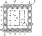
図1A〜図5は、本教示の実装形態による印刷製品を形成するための方法を描く。この実装形態では、印刷製品の形成は、印刷基材100の表面140に対して水平に配向された支持構造体の形成を含む。図1A〜図4Bでは、「A」図は、平面図のインプロセス構造体を描き、「B」図は断面内のインプロセス構造体を描き、断面位置は、対応する「A」図に破線で示されている。
1A-5 show a method for forming a printed product according to the implementation form of the present teaching. In this mounting embodiment, the formation of the printed product comprises the formation of a support structure that is horizontally oriented with respect to the
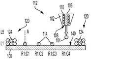
図1Aは平面図であり、図1Bは、図1Aの断面図であり、印刷ベッド及び印刷ヘッド102などの印刷基材(すなわち、基材)100を示している。印刷基材100は、静止していてもよく、印刷ヘッド102は、基材100に対して3つの軸(X方向、Y方向、及びZ方向)に移動してもよく、又は印刷ヘッド102は、静止していてもよく、印刷基材100は、印刷ヘッド102に対して3つの軸に移動してもよく、又は印刷基材100と印刷ヘッド102との両方が、1つ以上の軸内で互いに対して移動してもよいことが理解されるであろう。印刷ヘッド102は、電磁コイルなどのエジェクタ110を使用して、印刷ヘッド102の開口部108から印刷材料106の液滴104を排出するように構成されている。図は単一の印刷ヘッド102を描いているが、2つ以上の印刷ヘッド102及び/又は2つ以上の開口部108を有する印刷ヘッド102を有するプリンタが企図されていることが理解されるであろう。
1A is a plan view, FIG. 1B is a cross-sectional view of FIG. 1A, and shows a printing base material (that is, a base material) 100 such as a printing bed and a
液滴104は、印刷されるとき(すなわち、排出、分配、又は堆積されたとき)、液体金属液滴(例えば、銅、アルミニウム、鉛、スズ、チタンなど)などの液体材料、金属合金(例えば、青銅、インコネル、又はニッケル、クロム、ステンレス鋼などの鋼、及び鉄のうちの少なくとも1つを含む金属合金)、ポリマー(例えば、ナイロン、プラスチックなど)、又は別の好適な印刷材料を含むことができる。印刷基材100及び印刷ヘッド102は、例えば、MagnetoJet技術を含む金属/金属合金プリンタ112の一部であってもよい。このようなプリンタは、Vader Systems,Getzville,NYから入手可能である。
When the
図1A及び図1Bは、形成中の複数の柱114を更に描いている。説明のために、図は、4つの行(R1〜R4)及び4つの列(C1〜C4)に沿って4×4グリッドに配置された16本の柱114の形成を描いているが、16本よりも多い又は少ない柱を含む他の構造体も企図される。更に、柱は直線的に整列される必要はないが、形成される構造体の設計に応じて、曲線、円、又は別のパターンに沿って形成することができる。
1A and 1B further depict a plurality of
図1A及び図1Bは、完成した印刷製品500の少なくとも一部分を形成する複数の印刷された液滴124から形成された、インプロセス印刷製品120を更に描いている(図5、更に後述する)。印刷製品120は、典型的には、印刷ヘッド102を使用して印刷することによって形成され、したがって、複数の液滴として描かれているが、他の形成方法も企図される。図1Aでは、印刷製品120は、他の形状及び特徴部を有する印刷製品が企図されているが、印刷基材100に対して直角に形成され、印刷基材100から離れて延在する複数の壁(例えば、4つの壁)122を有するエンドレススクエア構造体として描かれている。
1A and 1B further depict an in-process printed
従来の金属印刷では、第1の液滴を印刷した直後に、第1の液滴上に第2の液滴を印刷することが望ましい。これにより、第2の液滴が第1の液滴上に印刷されるとき、第1の液滴がその融解温度に比較的近い温度であることを確実にする。第2の液滴が印刷されると、第2の液滴の熱質量は、その融解温度に既に比較的近い第1の液滴を加熱し、結果として、第1及び第2の液滴は、硬化後(例えば、乾燥、冷却、固化、凍結、又は他の方法で硬化した後)に、第1及び第2の液滴が融着し、それによって第1及び第2の液滴が共に良好に接着されることを確実にする。後続の液滴は、同様に、その融解温度に比較的近い温度にある前の液滴上に印刷され、これにより最終構造体を形成する液滴の全体が融着し、物理的な応力及び歪みからの損傷に対抗するようになる。印刷製品120は、構造的一体性及び堅牢性を確保するために、このように形成することができる。
In conventional metal printing, it is desirable to print a second droplet on the first droplet immediately after printing the first droplet. This ensures that when the second droplet is printed on the first droplet, the first droplet is at a temperature relatively close to its melting temperature. When the second droplet is printed, the thermal mass of the second droplet heats the first droplet, which is already relatively close to its melting temperature, and as a result, the first and second droplets After curing (eg, after drying, cooling, solidifying, freezing, or otherwise curing), the first and second droplets are fused, thereby both the first and second droplets. Ensure good adhesion. Subsequent droplets are also printed on the previous droplet, which is relatively close to its melting temperature, thereby fusing the entire droplet forming the final structure, resulting in physical stress and physical stress. It will resist damage from strain. The printed
しかしながら、支持構造体を形成する柱114は、一部の用途では、完成した製品500を形成する前に印刷製品120から除去されることになり、したがって、犠牲支持構造体である。柱114は、隣接する液滴間の機械的結合がより弱い場合には最も容易に除去されるが、印刷製品を完成するために除去されるまで、構造体が無傷のままであることを確実にするために十分に堅牢であるべきである。この実装形態では、所与の柱又は他の関連する支持構造体特徴部を形成するために使用される第1の液滴104は、第1の液滴上に第2の液滴104を印刷する前に硬化させることができる(例えば、乾燥、冷却、固化、凍結、又は他の方法による硬化)。しかしながら、印刷速度及び製品スループットを最大化するために、以前に印刷された液滴が硬化する間、他の柱114の他の液滴104の印刷が継続する。図1Aは、複数の柱114の印刷中に印刷ヘッド102によってとられた印刷経路130を描いている。図1A及び図1Bは、印刷ヘッド102が印刷経路130に沿って液滴104の印刷を完成し、位置R1:C4において最終的な液滴104を印刷することを描いている。位置R1:C4において液滴104を完成した後、印刷ヘッド102は、位置R1:C1において第2の液滴104を印刷し、次いで、次に他の位置R2:C1からR1:C4において印刷する。後続の層内の柱114の位置において印刷するとき、同じ印刷経路130又は同じ印刷経路130の少なくとも一部分を反復することは、液滴配置における不整合を低減することができ、後続の液滴が主に以前に印刷された液滴上に着地することを確実にするのに役立ち得る。
However, the
図1A及び図1Bは、柱114の印刷中のインプロセス印刷製品120の印刷を更に描いている。インプロセス印刷製品120の印刷は、インプロセス印刷製品120の印刷を実施することを含むことができ、インプロセス印刷製品120を形成する各液滴124は、以前に印刷された液滴124上に別の液滴124を印刷する前に硬化する必要はないが、柱114及び印刷製品120の各印刷層L1〜L6は、垂直に(すなわち、基材100の表面140から離れて)順次印刷されるので、任意の所望の印刷経路を使用することを実施され得る。換言すれば、L2などの液滴104、124を印刷する前に、L1の液滴104、124が印刷される。当業者に理解されるように、これにより、より低い層を印刷しながら、より高い、以前に印刷された構造体と印刷ヘッド102との間の物理的接触及び干渉を最小限に抑える。図1A及び図1Bでは、柱114の液滴104の1つの層L1が印刷され、印刷製品120の2つの層(L1及びL2)が印刷される。
1A and 1B further depict the printing of the in-
従来のプロセスでは、第1の液滴は、第2の液滴が直ちに第1の液滴上に印刷されたときに、依然として高温及び/又は溶融している。本教示の実装形態では、第2の液滴を印刷する前に各柱114の第1の液滴104を硬化させることにより、各液滴104が高温でありかつ/又は溶融している継続時間が短縮される。低い液滴印刷周波数を使用して印刷された柱114は、硬化前に(すなわち、固化する前に)減少した液滴流に起因して、より小さい最大直径を有する。本教示に従って形成された柱は、硬化していないか又は部分的に硬化した柱上に第2の液滴を印刷するときよりも再現可能な高さを有する柱を生成する。この改善された柱の高さの再現性は、制御が困難な後続の液滴を上部に印刷したときの溶融した液滴の平坦化が、本教示の実施により低減又は排除されるので、少なくとも部分的には結果として得られる。
In the conventional process, the first droplet is still hot and / or melted when the second droplet is immediately printed on the first droplet. In the embodiment of the present teaching, the duration at which each
図1A及び図1Bに描かれる構造体と同様の構造体を印刷した後、図2A及び図2Bに描かれるように印刷を継続することができ、柱114の3つの層(L1〜L3)が図1の印刷経路130を使用して印刷されており、インプロセス印刷製品120の4つの層(L1〜L4)は、任意の所望の印刷経路を使用して印刷されている。更に、いくつかの構造体では、柱114が印刷基材100の表面140の平面に直角になるように印刷を目標とすることが望ましい。場合によっては、特により高い柱114では、柱114は、直角ではなくなり、もたれること、転倒、傾斜などを起こしやすい場合がある。更に、比較的高い柱は、印刷中に弾性的に及び/又は塑性的に振動又は変形し、それによってその後印刷される液滴の配置精度が低下することがある。これらの問題を軽減又は排除するために、2つの隣接する柱114の間に、2つの隣接する柱114に物理的に接続及び架橋する任意選択の第1の横方向支持体200と、柱114のうちの1つと印刷製品120の壁122のうちの1つ又は2つ(R1:C1、R4:C1、R4:C4、R1:C4に位置する角柱114の例では)とを物理的に接続する第2の横方向支持体202とを堆積させることが好ましい場合がある。図2A及び図2Bは、レベルL3において印刷された横方向支持体200、202を描いているが、横方向支持体200、202は、任意のレベルにおいて印刷されてもよく、また2つ以上の異なるレベルにおいて印刷されてもよい。横方向支持体200、202を印刷するために、印刷ヘッド102は、印刷ヘッド102の開口部108から液滴104を排出する前に、部分的に形成された柱114のうちの1つの軸「A」から横方向にオフセットされる。これらの横方向又は対角支持体200、202は、柱114を補強しかつ剛性を高め、印刷及び/又は輸送中の柱114の横方向の移動を低減又は排除することができる。
After printing a structure similar to the structure depicted in FIGS. 1A and 1B, printing can be continued as depicted in FIGS. 2A and 2B, with the three layers (L1 to L3) of the
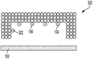
したがって、印刷は、柱114及びインプロセス印刷製品120が、図3A及び図3Bに描かれるように所望の高さまで印刷されるまで継続することができる。図3A及び図3Bでは、柱114の形成が完成している。図3Bは、説明の目的のために6層の高さ(L1〜L6)を印刷した柱114を描いているが、柱114は、任意の所望の高さに印刷することができる。柱114が壁122とは異なる高さで伸びる場合、柱114を印刷するために、より少ない又はより多い液滴の数のいずれを使用してもよく、これにより柱114の高さが壁と、そして単一の液滴によって生成される柱114の高さの変化の範囲内に互いに一致させることができる。次に、各隣接する柱114間の空間又は間隙300、及び各柱114と壁122との間の空間又は間隙300が充填されて、図4Bに描かれる支持表面400をレベルL6において形成する。支持表面400を形成する液滴を印刷するために、印刷ヘッド102は、印刷ヘッド102の開口部108から液滴104を排出する前に、完成した柱114のうちの1つの軸「A」から、及び壁122から横方向にオフセットされる。支持表面400を形成した後、支持表面400上に追加の印刷を継続して印刷キャップ402を形成することができ、印刷キャップ402は、複数の液滴層を含み、印刷キャップ402は壁122に接続されて、完成した印刷構造体404を形成する。したがって、印刷構造体404の形成中、柱114は支持表面400及び印刷キャップ402の印刷を可能にする支持を提供する。
Therefore, printing can continue until the
次に、図5に描かれるように、印刷基材100から完成した印刷構造体404が除去される。更に、いくつかの実装形態では、柱114及び(存在する場合)横方向支持体200、202を含む支持構造体は、完成した印刷製品500を形成するために印刷構造体404から除去され、したがって犠牲支持構造である。柱114及び横方向支持体200、202のいくつかの部分は、図示するように、完成製品500上に残ってもよく、又は完全に除去されてもよいことが理解されるであろう。
Next, as depicted in FIG. 5, the completed
この実装形態では、複数の柱の各柱114は、完成したときに、図3Bに描かれるように、複数の柱の他の柱114と同じ高さに形成される。本開示の目的のために、同じ高さを有する柱114は、複数の柱の全ての他の柱114の高さの±5%以内である高さを有する。これにより、印刷基材100の表面140に略平行な支持表面400の形成が可能になり、したがって、印刷基材100の表面140に対して水平に配向される。支持表面400は、完成したときに、基材100の表面140の平面に対して約0°(すなわち平行)〜約10°、又は約0°〜約5°の角度を形成する。
In this implementation, each
更に、印刷経路130に沿って柱114を形成する複数の液滴104を印刷することは、印刷ヘッド102から複数の印刷位置(すなわち、R1:C1からR1:C4までの各位置)の各々において、印刷材料の第1の液滴のみを順次排出することを含む。その後、印刷材料の第2の液滴104のみが、複数の柱位置の各々において、第1の液滴104上に順次排出される。最後に、複数の柱114を形成するために、追加の液滴が柱位置のうちの2つ以上において順次排出される。各柱位置において順次印刷することにより、各液滴が、後続の印刷される液滴上に別の液滴を印刷する前に、完全に硬化する(例えば、冷却する)ことを確実にする。柱114を印刷するために使用される液滴とは対照的に、完成した印刷製品500を印刷するために使用される液滴は、上の液滴が完全に硬化する前に印刷されるように印刷され得る。これにより、完成した印刷製品500の構造的堅牢性が向上し、柱114の除去を軽減する。
Further, printing the plurality of
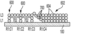
図6A〜図11は、本教示の別の実装形態を描いている。この実装形態では、柱600は、印刷製品602の特徴部のための支持構造体を提供するように形成され、支持構造体は、印刷基材100に対して斜めの角度で表面を含む。支持構造体は、その後、印刷製品1100の完成前に、より詳細に後述するように、この機能を提供した後に、少なくとも部分的に除去することができる。角度付けされた支持構造体は、印刷製品602が基材100に対して張り出し部を含むことを可能にする。この実装形態では、図1A及び図5に関連して上述した実装形態と同様に、各柱600の各液滴104が印刷され、次いで、柱114の以前に印刷された液滴上に別の液滴104を印刷する前に硬化させる。しかしながら、製品スループットを最大化するために、印刷ヘッド102は、各以前に印刷された液滴104が硬化している間に、他の柱600の液滴104を印刷し続ける。
6A to 11 show another embodiment of the present teaching. In this mounting embodiment, the
図6Aは、4×4グリッドの各柱600の各液滴104を印刷するための例示的な印刷経路606を描いている。印刷経路606は、印刷経路130と同じであっても異なっていてもよい。印刷経路606及び柱600の形成を実行するために、印刷ヘッド102は、最初に、位置R1:C1において柱600に対して単一の第1の液滴104を堆積させ、次に、位置R2:C1において柱600に対して単一の第1の液滴104を堆積させる。図6Bに描かれるように、液滴104が位置R1:C4において印刷されると、液滴104の第1の層「L1」の印刷が完成する。したがって、R1:C1における液滴104は、印刷ヘッド102が4×4グリッドの他の15個の液滴を印刷する継続時間中に硬化する。図6Bはまた、印刷製品602を形成する液滴604の印刷による印刷製品602の第1の層「L1」の形成も描いている。例示のために、印刷製品602を形成する印刷される液滴604は、柱600を形成する印刷される液滴104とは異なるハッチングで描かれている。しかしながら、液滴604は、印刷ヘッド102によって印刷されたときに、液滴104と同じサイズ及び組成であり得ることが理解されるであろう。柱600を形成する層L1〜L10の各々の液滴104は、支持構造体900の各層L1〜L10(詳細に後述する図8A及び図8B)が順次印刷されるように、印刷経路606によって示される順序で印刷される。各液滴604は以前に印刷された液滴604上に別の液滴604を印刷する前に硬化する必要がないため、印刷製品602は、任意の所望の印刷経路に印刷されてもよく、柱600の各層L1〜L10及び印刷構造体602は、垂直に(すなわち、基材100の表面140から離れて)印刷される。換言すれば、L2の液滴を印刷する前に、L1の液滴104、604が印刷される。当業者に理解されるように、これにより、より低い層を印刷しながら、より高い、以前に印刷された構造体と印刷ヘッド102との間の物理的接触及び干渉を最小限に抑える。図6A及び図6Bでは、印刷製品602の1つの層L1が印刷される。
FIG. 6A depicts an
一旦液滴104、604の第1の層L1が印刷されると、印刷ヘッド102は、再び印刷経路606を実行して、後続の液滴104を印刷することができる。すなわち、印刷ヘッド102は、位置R1:C1において、柱600に対して層L1の第1の液滴104上に層L2の第2の液滴104を堆積させ、位置R2:C1において、柱600に対して層L1の第1の液滴104上に層L2の第2の液滴104を堆積させ、以下同様に続く。したがって、印刷製品602及び柱600の印刷は継続することができ、印刷ヘッド102は反復的に追従し、印刷経路606に沿って連続印刷を実行して4×4グリッドの柱600を印刷する。印刷ヘッド102が追従する印刷経路は、層間で変化し得るが、2つの液滴104が任意の単一の柱600に対して順次印刷されず、その結果、各柱600に対して印刷される液滴104は、硬化するのに十分な時間を有することが理解されるであろう。この実装形態では、一般的に、印刷製品602が支持構造体900を覆うので、印刷製品602の所与の層を形成する液滴604は、一般的に、支持構造体900の所与の層を形成する液滴104を排出した後に、印刷ヘッド102の開口部108から排出される。しかしながら、いくつかの用途では、印刷製品602の対応する層を印刷する前に、支持構造体900の1つ以上の層を印刷することが望ましい場合がある。
Once the first layer L1 of the
したがって、印刷は、柱600及び印刷構造体602が完成するまで継続することができる。
Therefore, printing can be continued until the
柱600の印刷中に、柱600の軸Aから横方向にオフセットされた液滴700を任意選択的に印刷することができる。横方向にオフセットされた液滴700の位置は、支持構造体900の設計によって異なる。図7Bでは、3つの横方向にオフセットされた液滴700が、位置R1:C4において液滴104に付着して描かれており、そのうちの2つは、図7Aで見出すことができる。横方向にオフセットされた液滴700はまた、図7Aにも描かれているように、列C4の各柱600において(すなわち、R1:C4、R2:C4、R3:C4、及びR4:C4の各々の位置において)も形成される。これらの横方向にオフセットされた液滴700は、印刷基材100の表面140の平面に直角に印刷することができる。場合によっては、特により高い柱600では、柱600は、例えば、図2A及び図2Bを参照して上述したように、例えば、直角から離れて、もたれること、転倒、傾斜、振動、塑性変形、及び/又は弾性変形などを起こしやすい場合がある。横方向にオフセットされた液滴700は、2つの隣接する柱600を物理的に接続する任意選択的な横方向支持体702を形成することができる。図7A及び図7Bは、レベルL3において印刷された横方向支持体702を描いているが、横方向支持体702は、任意のレベルにおいて印刷されてもよく、また2つ以上の異なるレベルにおいて印刷されてもよい。横方向支持体702を印刷するために、印刷ヘッド102は、印刷ヘッド102の開口部108から液滴104を排出する前に、部分的に形成された柱600の1つの軸「A」から横方向にオフセットされる。
During printing of the
これらの横方向にオフセットされた液滴700は、支持構造体900の一部である支持表面としての傾斜面902(図9)の形成を支援する。傾斜面902は、印刷ヘッド102を使用して印刷される液滴104で柱600間の空間に充填することによって形成される。したがって、印刷構造体602を形成する液滴604を印刷する前に、各層において空間を充填する液滴104が印刷される。図8は、図7Bの平面図であり、印刷製品602が除去されている。図8は、部分的に完成した支持構造体900及び部分的に完成した傾斜面902を描いている。図9Bを参照すると、傾斜面902は、斜角シータ「Θ」で形成され、ここで、Θは、柱600のうちの1つを通る垂直軸Aと、柱600の各々の最上部の液滴104の中心を通る最適適合線(すなわち、近似曲線)である斜線904によって画定される。一実装形態では、Θは、約20°〜約70°、又は約30°〜約60°であり得る。
These laterally offset
その後、柱600の横方向にオフセットされた液滴700及び傾斜面902の印刷は、図9A及び図9Bに描かれる構造体を形成し続ける。図9A及び図9Bでは、傾斜面902を含む支持構造体900が完成している。印刷製品602に追加するための液滴604の更なる印刷は、その後、印刷製品602の印刷を完成する図10A及び図10Bの構造体を形成するために継続することができる。図10Bでは、柱600は、10のレベルの高さ(L10)であり、印刷製品602は、13のレベルの高さ(L13)であるように描かれているが、柱600及び印刷製品602は、印刷基材100の表面140に対して任意の所望の高さに形成することができる。
The printing of the laterally offset
その後、印刷製品602を印刷基材100から除去することができ、いくつかの実装形態では、柱600及び支持構造体900は、図11に描かれているような最終印刷製品1100をもたらすように除去することができ、したがって、柱600及び支持構造体900は、犠牲的であってもよい。支持構造体900(柱600、横方向支持体702、及び傾斜面902)からのいくつかの印刷される液滴104は、図示のように最終印刷製品1100上に留まってもよく、又は完全に除去されてもよいことが理解されるであろう。
The
柱600のパターンは、印刷ヘッド102の直線移動を伴う蛇行パターンを使用して印刷された正方形の配列として描かれているが、直線ではない他のパターンの柱が湾曲した経路、又は湾曲した経路への近似に沿って印刷されてもよいことが企図される。これは、一連の柱が曲線に沿って印刷される場合に有益であり得、ここで、全ての柱は、3D部品が同じ層において構築される固体表面に当たる場合に有益であり得る。したがって、その一連の柱を印刷する経路の部分は、固体表面を形成するためにそれらを接続する必要があるまで反復することができる。その時点で、印刷ヘッドが同じ印刷経路又は印刷経路の一部分を横切る間に、その一連の柱を接続するドットを印刷することができる。第2の印刷経路で印刷された隣接する一組の柱にその一連の柱を接続する線は、第2の印刷経路が第1の印刷経路に対して平行な曲線である場合には、第1の印刷経路に平行な曲線であってもよく、又は第1の印刷経路と第2の印刷経路との間に補間されてもよい。
The pattern of the
本教示の実装形態において、隣接する柱は、特に上述のような横方向支持体が使用される場合に、間隔が近い非常に小さな液滴に対して約0.1ミリメートル(mm)〜約10.0mmの距離で互いに離間するように印刷することができる。他の実装形態では、隣接する柱は、約1.0mm〜約5.0mm、又は約2.0mm〜約3.0mmの距離で互いに離間させることができる。印刷される液滴は、約50マイクロメートル(μm)〜約700μm、又は約200μm〜約600μm、又は約400μm〜約500μmの平均直径を有することができる。更に、完成した柱は、横方向支持体によって支持されていない場合、約0.2mm(滴径に応じて)〜約1.0メートルの高さを有することができる。場合によっては、柱の高さは、動的負荷、熱変形などに応じて、1.0メートルを超え、例えば約1.0メートル〜1.8メートルであり得る。柱は、約1.8メートルを超える高さで自己座屈になると推定される。横方向支持体によって支持される場合、柱の高さは、約0.2mm〜数メートル、例えば、3.0メートル以上の範囲であり得る。典型的には、形成される構造体に応じて、柱の高さは、約1.00mm〜約500mm、又は約1mm〜約300mmの範囲であり得る。 In the implementation of the present teaching, adjacent columns are about 0.1 mm (mm) to about 10 for very small droplets that are closely spaced, especially when lateral supports as described above are used. It can be printed so as to be separated from each other at a distance of 0.0 mm. In other implementations, adjacent columns can be separated from each other at a distance of about 1.0 mm to about 5.0 mm, or about 2.0 mm to about 3.0 mm. The droplets to be printed can have an average diameter of about 50 micrometers (μm) to about 700 μm, or about 200 μm to about 600 μm, or about 400 μm to about 500 μm. In addition, the finished column can have a height of about 0.2 mm (depending on the drop diameter) to about 1.0 meter if not supported by a lateral support. In some cases, the height of the columns can exceed 1.0 meters, for example about 1.0 meters to 1.8 meters, depending on the dynamic load, thermal deformation and the like. The column is estimated to be self-buckling at a height of more than about 1.8 meters. When supported by a lateral support, the height of the columns can range from about 0.2 mm to a few meters, for example 3.0 meters or more. Typically, the height of the columns can range from about 1.00 mm to about 500 mm, or from about 1 mm to about 300 mm, depending on the structure being formed.
この実装形態では、複数の柱の各柱114は、完成したときに、図10Bに描かれるように、複数の柱のうちの他の柱114の各々とは異なる高さを有する。一実装形態では、各柱114は、複数の柱の全ての他の柱114よりも±10%高い又はより短い高さを有する。別の実装形態では、複数の柱の各柱は、完成したときに、高さを有し、複数の柱のうちの最も高い柱の高さは、複数の柱のうちの最も短い柱の高さの少なくとも4倍である。これにより、傾斜面902を形成して、印刷基材100の表面140に対する斜角を形成することができる。
In this embodiment, each
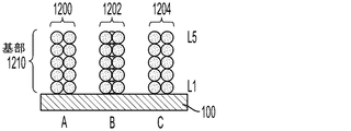
上述のように、横方向支持体200、202、702は、柱114、600が形成されている間、及び除去される前に、柱114、600の支持を提供し、これにより、柱114、600のもたれ又は転倒が低減される。横方向支持体200、202、702は、柱114、600を支持し、柱114、600は、印刷製品500、1100の完成前に印刷製品500、1100の少なくとも一部分を支持する。別の実装形態では、柱を支持するための代替的な技術が、図12A〜図13Bに描かれるように提供され、ここで、「A」図が平面図であり、「B」図が「A」図で特定された位置に沿った断面である。図12A〜図13Bでは、異なるタイプの基部1210を有する柱1200〜1204の3つの列A〜Cが描かれている。列Aの柱1200は、1レベル当たり2つの液滴1220を含み、列Bの柱1202は、1レベル当たり3つの液滴1220を含み、列Cの柱1204は、1レベル当たり4つの液滴1220を含む。例示の目的で3つの異なるタイプの基部1210が描かれており、各列A〜Cは異なるタイプの基部1210を含むが、構造体は、基部1210のタイプのうちの1つのみを有する複数の列を含み得ることが理解されるであろう。しかしながら、構造体は、列A〜Cに描かれる2つのタイプの基部1210、又は3つのタイプの全ての基部を含み得ることが更に理解されるであろう。
As mentioned above, the lateral supports 200, 202, 702 provide support for the
図12A及び図12Bの基部1210を形成するために、第1の液滴1220のみが、各列A〜Cの各基部1210に対してレベルL1において印刷される。その後、第2の液滴1220は、第1の液滴に隣接する各列A〜C内の各基部1210に対してレベルL1において印刷される。柱1202及び1204では、第3の液滴1220は、第1の2つの液滴1220に隣接する各基部に対してL1において印刷され、柱1204では、第4の液滴1220は、第1の3つの液滴に隣接する各基部1210に対してL1において印刷される。各柱1200〜1204に対して一度に1つの液滴1220を印刷することにより、各柱位置における各基部1210に対して先行する液滴に隣接する後続の液滴を印刷する前に、各液滴1220が硬化することを確実にする。滴1220は、例えば、前述の印刷経路130、606のうちの1つ、又は別の印刷経路に印刷することができる。後続の液滴1220は、各柱1200〜1204の基部1210が完成するまで、追加のレベルにおいて同様に印刷される。図12Bは、各基部1210を形成するための5つのレベルL1〜L5を描いているが、基部は、5つのレベルよりも多くてもよい、又は少なくてもよいことが理解されるであろう。各レベルL1〜L5に対しての液滴1220は、同じレベルにおける少なくとも1つの他の液滴1220と、異なるレベルにおける少なくとも1つの他の液滴1220とに物理的に接触することができる。
To form the base 1210 of FIGS. 12A and 12B, only the
次に、図13A及び図13Bに描かれるように、各基部1210上に剥離部1300を印刷する。剥離部1300は、各レベルL6〜L8において印刷された単一の液滴1220を含む。図13Bは、剥離部が3つのレベルの高さであるように描かれているが、剥離部1300は、1つ以上のレベルの高さであり得る。その後、上で描写及び説明されている印刷キャップ402などの上の構造体(簡略化のために図13A及び図13Bには描かれていない)、又は別の上の構造体が、剥離部1300に物理的に接触するように形成されてもよい。
Next, the peeling
柱1200〜1204の形成及び使用中、各レベルにおいて2つ以上の液滴1220を含む基部1210は、例えば、各レベルにおいて単一の液滴のみを含む柱と比較して、柱1200〜1204に対して比較的強い安定した支持を提供する。補強基部1210で形成されたこれらの柱1200〜1204は、横方向支持体200、202、702などの別個の支持構造体を必要としない場合があるが、柱1200〜1204を更に支持するために横方向支持体が形成されてもよいことが企図される。更に、各剥離部1300は、単一の液滴1220のみで印刷キャップ402などの上の構造体に物理的に接触し、したがって、製品との物理的な接続は弱く、柱1200〜1204を含む支持構造体は、柱1200〜1204が表面140から製品までの基部1210のみを含むように形成されている場合よりも容易に除去される。したがって、比較的より強い補強基部1210は、各列A〜Cの各柱1200〜1204を強化し、形成中の柱1200〜1204の転倒を低減又は防止する一方で、比較的弱い剥離部1300は、製品との接触点として各柱1200〜1204に対する単一の液滴1220を含むことによって、製品からの分離を軽減又は防止する。
During the formation and use of columns 1200-1204, the base 1210, which contains two or
図14は、製品から容易に分離される支持構造体を形成するために使用され得る2つの追加のタイプの柱を示す断面図である。柱1400の第1のタイプXは、互いに横方向にオフセットされた複数の液滴1220を含む。図14は、第1の液滴1410が印刷基材100の表面140に物理的に接触する柱1400の第1の液滴1410の中心を通って延在する第1の垂直軸A1を描いている。図14は、柱1400の第2の液滴1412の中心を通って延在する第2の垂直軸A2を更に描いており、第2の液滴1412は、印刷キャップ402(図4、簡略化のために図示されていない)などの製品に物理的に接触する。柱1400は、第1の液滴1410と第2の液滴1412との間に位置付けられた追加の液滴1220を含むことができる。第1の軸A1は、第2の軸A2から距離D1だけ横方向にオフセットされている。一態様では、距離D1は、液滴の平均直径に応じて、約200μm〜約2,800μmであり得る。別の態様では、距離D1は、液滴1220の平均又は目標直径の約1.0倍〜約10.0倍であり得(目標直径は、液滴1220の中心を通って任意の方向、例えば、X方向、Y方向、若しくはZ方向のいずれか、又は液滴1220の中心を通る任意の回転方向で測定することができる)。図14では、柱1400を形成する複数の隣接する液滴1220は、柱1400が徐々に屈曲し、円弧1414を形成するように、互いに横方向にオフセットされる。
FIG. 14 is a cross-sectional view showing two additional types of columns that can be used to form support structures that are easily separated from the product. A first type X of
図14は、更に、柱1402の第2のタイプYが、互いに横方向にオフセットされた複数の液滴1220を含むことを描いている。図14は、第1の液滴1420が印刷基材100の表面140に物理的に接触する、柱1402の第1の液滴1420の中心を通って延在する第3の垂直軸A3を描いている。図14は、柱1402の第2の液滴1422の中心を通って延在する第4の垂直軸A4を更に描いており、ここで、第2の液滴1422は、印刷キャップ402(図4、簡略化のために図示されていない)などの製品に物理的に接触する。柱1402は、第1の液滴1420と第2の液滴1422との間に位置付けられた追加の液滴1220を含むことができる。いくつかの液滴1220の中心を通って延在する第3の軸A3は、第4の軸A4から横方向にオフセットされ、これはまた、いくつかの滴1220の中心を通って距離D2だけ延在してもよい。一態様では、距離D2は、約10μm〜約560μmであり得る。別の態様では、距離D2は、液滴1220の平均又は目標直径の約0.2倍〜約0.8倍であり得る。図14では、柱1400を形成する2つの隣接する液滴1220のみが、互いに横方向にオフセットされている。柱1402を形成する液滴1220の各々は、2つの軸A3及びA4のうちの1つのみに垂直に整列される。
FIG. 14 further illustrates that the second type Y of
柱1400、1402のいずれかは、互いに横方向にオフセットされた液滴1220を含む。横方向のオフセットは、列が単一の軸のみに沿って垂直に整列されている場合よりも、分離中に横方向のオフセットの位置(複数可)により大きな応力をかけることによって、製品からの分離を軽減する。図示及び記載されたもの以外の横方向オフセットが企図され、本教示の範囲内であることが理解されるであろう。
One of the
本教示の実装形態による方法は、例えば、加熱プロセス(例えば、再溶融プロセス、焼戻しプロセスなど)、エッチングプロセス(例えば、化学エッチング、機械的エッチングなど)、コーティングプロセス(例えば、金属めっきプロセス、ポリマーコーティングプロセスなど)、又は別の処理を含む、簡略化のために本明細書に記載されていない他の処理行為を任意に含み得ることが理解されるであろう。 The method according to the embodiment of the present teaching is, for example, a heating process (eg, remelting process, tempering process, etc.), an etching process (eg, chemical etching, mechanical etching, etc.), a coating process (eg, metal plating process, polymer coating, etc.). It will be appreciated that it may optionally include other processing actions not described herein for the sake of brevity, including (process, etc.), or other processing.
本教示の広い範囲を記載する数値範囲及びパラメータは近似値であるが、特定の実施例に記載される数値は、可能な限り正確に報告される。しかしながら、いずれの数値も、それぞれの試験測定値に見出される標準偏差から必然的に生じる特定の誤差を本質的に含む。更に、本明細書に開示される全ての範囲は、その中に包含される任意の及び全ての小範囲を包含すると理解されるべきである。例えば、「10未満」の範囲は、ゼロの最小値と10の最大値との間(境界値を含む)の任意の及び全てのサブ範囲、すなわち、ゼロ以上の最小値と10以下の最大値とを有する任意の及び全てのサブ範囲、例えば、1〜5を含むことができる。特定の場合では、パラメータについて記載した数値は、負の値をとることができる。この場合、「10未満」と記載された範囲の例示的な値は、負の値、例えば、−1、−2、−3、−10、−20、−30などを想定することができる。 While the numerical ranges and parameters that describe the broad range of this teaching are approximations, the numerical values that describe the particular examples are reported as accurately as possible. However, each number essentially contains certain errors that inevitably result from the standard deviation found in each test measurement. Moreover, it should be understood that all scopes disclosed herein include any and all subranges contained therein. For example, the range "less than 10" is any and all subranges between the minimum value of zero and the maximum value of 10 (including the boundary value), that is, the minimum value greater than or equal to zero and the maximum value less than or equal to 10. Any and all subranges with and can be included, for example 1-5. In certain cases, the numbers described for the parameters can be negative. In this case, the exemplary values in the range described as "less than 10" can be assumed to be negative values, such as -1, -2, -3, -10, -20, -30 and the like.
1つ以上の実装形態に関して本教示は例示されているが、添付の特許請求の範囲の趣旨及び範囲から逸脱することなく、改変及び/又は修正を例示の実施例に対して行うことができる。例えば、プロセスが一連の行為又は事象として記載されているが、本教示は、かかる行為又は事象の順序によって限定されないことが理解されるであろう。いくつかの行為は、本明細書に記載されるものとは異なる順序で、及び/又は別の他の行為若しくは事象と同時に生じ得る。また、本教示の1つ以上の態様又は実装形態による方法論を実装するために、全てのプロセス段階が必要とされるとは限らない場合がある。構造的構成要素及び/又は処理段階を追加することができ、又は既存の構造的構成要素及び/又は処理段階を除去又は修正することができることが理解されるであろう。更に、本明細書に描写される行為のうちの1つ以上は、1つ以上の別個の行為及び/又は局面において実行されてもよい。更に、用語「含む(including)」、「含む(includes)」、「有する(having)」、「有する(has)」、「有する(with)」、又はこれらの変形が発明を実施するための形態及び特許請求の範囲のいずれかで使用される限りにおいて、そのような用語は、用語「含む(comprising)」と同様の手法での包含であることが意図される。用語「〜のうちの少なくとも1つ」は、列挙された項目のうちの1つ以上を選択することができることを意味するために使用される。本明細書で使用するとき、例えば、A及びBなどの項目のリストに関して用語「のうちの1つ以上」は、A単独、B単独、又はA及びBを意味する。更に、本明細書の記述及び特許請求の範囲において、2つの材料に関して使用される用語「上(on)」、すなわち、他方「上(on)」の一方は、それらの材料間の少なくとも一部の接触を意味し、一方、「の上(over)」は、それらの材料が近接していることを意味するが、場合によっては、接触が可能であるが必要とされないように、1つ以上の追加の介在材料を伴うことを意味する。「上(on)」又は「の上(over)」のいずれも、本明細書で使用される際に任意の指向性を暗示しない。「共形」という用語は、下にある材料の角度が共形材料によって維持される被覆材料を説明する。「約」という用語は、変更が例示された実装形態へのプロセス又は構造の非適合性をもたらさない限り、列挙された値が幾分変化してもよいことを示す。最後に、「例示的な」は、その記載が理想的であることを暗示するのではなく、一実施例として使用されることを示す。本教示の他の実装形態は、明細書及び本明細書の開示の実施を考慮することで当業者には明らかとなるであろう。本明細書及び実施例は、単に例示として見なされることが意図され、本教示の真の範囲及び趣旨は、以下の特許請求の範囲によって示される。 Although this teaching is exemplified for one or more implementations, modifications and / or modifications can be made to the exemplary embodiments without departing from the spirit and scope of the appended claims. For example, although the process is described as a series of actions or events, it will be understood that this teaching is not limited by the order of such actions or events. Some actions may occur in a different order than those described herein and / or at the same time as another action or event. Also, not all process steps may be required to implement a methodology according to one or more aspects or implementations of this teaching. It will be appreciated that structural components and / or processing steps can be added, or existing structural components and / or processing steps can be removed or modified. Further, one or more of the acts described herein may be performed in one or more separate acts and / or aspects. Further, the terms "including", "includes", "having", "has", "with", or variations thereof for carrying out the invention. And as far as it is used in the claims, such terms are intended to be inclusion in a manner similar to the term "comprising". The term "at least one of" is used to mean that one or more of the listed items can be selected. As used herein, for example, with respect to a list of items such as A and B, the term "one or more of" means A alone, B alone, or A and B. Further, within the description and claims of the present specification, one of the terms "on" used with respect to the two materials, i.e. the other "on", is at least a portion between those materials. On the other hand, "over" means that the materials are in close proximity, but in some cases one or more so that contact is possible but not required. Means that it involves additional intervening material. Neither "on" nor "over" implies any directivity as used herein. The term "conformal" describes a coating material in which the angle of the underlying material is maintained by the conformal material. The term "about" indicates that the listed values may vary somewhat as long as the changes do not result in process or structural incompatibility with the illustrated implementation. Finally, "exemplary" does not imply that the description is ideal, but indicates that it is used as an example. Other implementations of this teaching will become apparent to those skilled in the art by considering the specification and the implementation of the disclosure herein. The present specification and examples are intended to be viewed merely as an example, and the true scope and gist of this teaching is set forth by the following claims.
本明細書で使用されるとき、相対位置の用語は、ワークピースの向きにかかわらず、ワークピースの慣習的な平面又は加工面に平行な平面に基づいて定義される。本明細書で使用されるとき、「水平」又は「横方向」という用語は、ワークピースの向きにかかわらず、ワークピースの慣習的な平面又は加工面に平行な平面として定義される。用語「垂直」は、水平に対して直角な方向を指す。「上」、「側」(「側壁」におけるような)、「より高い」、「より低い」、「の上」、「上部」、及び「下」などの用語は、ワークピースの向きにかかわらず、ワークピースの上面上にある慣習的な平面又は加工面に対して定義される。
As used herein, the term relative position is defined based on the customary plane of the workpiece or the plane parallel to the machined plane, regardless of the orientation of the workpiece. As used herein, the term "horizontal" or "horizontal" is defined as the conventional plane of a workpiece or a plane parallel to a machined plane, regardless of the orientation of the workpiece. The term "vertical" refers to the direction perpendicular to the horizontal. Terms such as "top", "side" (as in "side wall"), "higher", "lower", "top", "top", and "bottom" are related to the orientation of the workpiece. It is defined for the customary flat surface or machined surface on the top surface of the workpiece.
Claims (20)
前記複数の柱位置の各々において印刷ヘッドから印刷材料の第1の液滴のみを順次排出することと、次いで、
前記複数の柱位置の各々において前記第1の液滴上に前記印刷ヘッドから前記印刷材料の第2の液滴のみを順次排出することと、次いで、
前記柱位置のうちの2つ以上において前記印刷材料の追加の液滴を順次排出して、前記複数の柱を形成することと、を含む、方法。 A method for forming a three-dimensional printed structure, wherein the printed structure includes a plurality of columns at a plurality of column positions, and the method is described.
Only the first droplet of the printing material is sequentially ejected from the print head at each of the plurality of column positions, and then,
Only the second droplet of the printing material is sequentially ejected from the printing head onto the first droplet at each of the plurality of column positions, and then,
A method comprising sequentially ejecting additional droplets of the printing material at two or more of the column positions to form the plurality of columns.
前記複数の柱の隣接する柱間に複数の液滴を順次堆積させて、前記基材の前記表面に略平行な支持表面を形成することと、を更に含む、請求項2に記載の方法。 Droplets are sequentially deposited on the surface of the substrate at the plurality of column positions of the plurality of columns to complete the formation of the plurality of columns, and then
The method according to claim 2, further comprising sequentially depositing a plurality of droplets between adjacent columns of the plurality of columns to form a support surface substantially parallel to the surface of the substrate.
前記複数の柱の隣接する柱間に複数の液滴を順次堆積させて、前記基材の前記表面の平面に対して斜めの勾配表面を有する支持表面を形成することと、を更に含む、請求項7に記載の方法。 Droplets are sequentially deposited at all column positions on the surface of the substrate to complete the formation of the plurality of columns, and then
Claims further include the sequential deposition of a plurality of droplets between adjacent columns of the plurality of columns to form a supporting surface having a gradient surface oblique to the plane of the surface of the substrate. Item 7. The method according to Item 7.
前記印刷ヘッドが、前記複数の柱位置の各々において前記第2の液滴のみの前記排出中に前記印刷経路を反復し、
前記印刷ヘッドが、前記柱位置のうちの前記2つ以上において前記追加の液滴の前記順次排出中に前記印刷経路を反復して、前記複数の柱を形成する、請求項1に記載の方法。 The print head follows the print path during the ejection of only the first droplet at each of the plurality of column positions.
The print head repeats the print path during the discharge of only the second droplet at each of the plurality of column positions.
The method of claim 1, wherein the print head repeats the print path during the sequential discharge of the additional droplets at the two or more of the pillar positions to form the plurality of pillars. ..
前記印刷キャップの前記印刷の後に前記印刷構造体から前記複数の柱を除去することと、を更に含む、請求項1に記載の方法。 By printing a printing cap that covers the plurality of columns and is in physical contact with the plurality of columns, the plurality of columns physically support the printing cap during the printing of the printing cap. To print and to
The method of claim 1, further comprising removing the plurality of columns from the printed structure after the printing of the printing cap.
第1の複数のレベルを含む基部であって、前記第1の複数のレベルの各レベルが、前記印刷材料の少なくとも2つの液滴を含み、前記少なくとも2つの液滴が、互いに物理的に接触する、基部と、
第2の複数のレベルを含む剥離部であって、前記第2の複数のレベルの各レベルが、前記印刷材料の1つの液滴のみを含む、剥離部と、を含むように印刷することを更に含む、請求項1に記載の方法。 The multiple pillars
A base comprising a first plurality of levels, each level of the first plurality of levels containing at least two droplets of the printing material, the at least two droplets being in physical contact with each other. To the base and
Printing is performed so as to include a peeling portion including a second plurality of levels, wherein each level of the second plurality of levels includes a peeling portion containing only one droplet of the printing material. The method according to claim 1, further comprising.
前記第1の複数のレベルの各々における各液滴が、同じレベルにおける少なくとも1つの他の液滴と、そして異なるレベルにおける少なくとも1つの他の液滴と物理的に接触する、請求項16に記載の方法。 Each level of the first plurality of levels comprises at least four droplets of the printing material.
16. The 16th aspect, wherein each droplet at each of the first plurality of levels is in physical contact with at least one other droplet at the same level and at least one other droplet at different levels. the method of.
前記複数の柱の各柱の各剥離部から前記印刷キャップを分離することと、を更に含む、請求項17に記載の方法。 Printing a printing cap that covers the base portion and the peeling portion of each of the plurality of pillars and physically contacts the peeling portion of each of the plurality of pillars, wherein the plurality of pillars are said to have the said peeling portion. To physically support, print, and print the print cap during the printing of the print cap.
17. The method of claim 17, further comprising separating the print cap from each peeling portion of each of the plurality of pillars.
方法を使用して犠牲支持構造体を形成することであって、前記方法が、
複数の柱位置の各々において印刷ヘッドから印刷材料の第1の液滴のみを順次排出することと、
各第1の液滴を硬化させることと、次いで、
各第1の液滴を硬化させた後に、前記複数の柱位置の各々において前記第1の液滴上に前記印刷ヘッドから前記印刷材料の第2の液滴のみを順次排出することと、
各第2の液滴を硬化させることと、次いで、
各第2の液滴を硬化させた後に、前記柱位置のうちの2つ以上において前記印刷材料の追加の液滴を順次排出して、複数の柱を形成することと、を含む、犠牲支持構造体を形成することと、
複数の第3の液滴を複数の第4の液滴上に、前記複数の第4の液滴が硬化していない間に排出することを含む方法を使用して、前記3次元印刷製品を形成することと、
前記犠牲支持構造体を前記3次元印刷製品から分離することと、を含む、方法。 A method for forming 3D printed products
The method is to form a sacrificial support structure, said method.
In order to eject only the first droplet of the printing material from the printing head at each of the plurality of column positions,
Curing each first droplet and then
After curing each first droplet, only the second droplet of the printing material is sequentially discharged from the print head onto the first droplet at each of the plurality of pillar positions.
Curing each second droplet and then
After curing each second droplet, sacrificial support, including forming multiple columns by sequentially ejecting additional droplets of the printing material at two or more of the column positions. Forming a structure and
The three-dimensional printed product is made using a method comprising ejecting a plurality of third droplets onto a plurality of fourth droplets while the plurality of fourth droplets are not cured. To form and
A method comprising separating the sacrificial support structure from the three-dimensional printed product.
前記複数の柱位置の各々において基材の表面上に印刷ヘッドから印刷材料の第1の液滴のみを順次排出して、第1の印刷層を形成することと、次いで、
前記複数の柱位置の各々における前記第1の液滴上に前記印刷ヘッドから前記印刷材料の第2の液滴のみを順次排出して、前記第1の印刷層上に第2の印刷層を形成することであって、各第2の液滴が、前記第1の液滴のうちの1つと垂直に整列される、形成することと、次いで、
前記柱位置のうちの2つ以上において前記印刷材料の追加の液滴を順次排出することであって、各追加の液滴が、前記第2の液滴のうちの1つと垂直に整列される、排出することと、
前記追加の液滴から横方向にオフセットされた複数の液滴を印刷して、複数の横方向支持体を形成することであって、各横方向支持体が、2つの隣接する柱を架橋する、形成することと、を含む、方法。
A method for forming a three-dimensional printed structure, wherein the printed structure includes a plurality of columns at a plurality of column positions, and the method is described.
At each of the plurality of column positions, only the first droplet of the printing material is sequentially discharged from the printing head on the surface of the base material to form the first printing layer, and then the first printing layer is formed.
Only the second droplet of the printing material is sequentially discharged from the printing head on the first droplet at each of the plurality of column positions, and the second printing layer is formed on the first printing layer. To form, where each second droplet is aligned perpendicular to one of the first droplets, and then to form.
By sequentially ejecting additional droplets of the printing material at two or more of the column positions, each additional droplet is aligned perpendicular to one of the second droplets. , Discharging and
Printing a plurality of droplets laterally offset from the additional droplet to form a plurality of lateral supports, each lateral support bridging two adjacent columns. , Forming and, including, methods.
Applications Claiming Priority (2)
| Application Number | Priority Date | Filing Date | Title |
|---|---|---|---|
| US16/666,212 US11235382B2 (en) | 2019-10-28 | 2019-10-28 | Method for supporting three dimensional (3D) printed features |
| US16/666,212 | 2019-10-28 |
Publications (2)
| Publication Number | Publication Date |
|---|---|
| JP2021066955A true JP2021066955A (en) | 2021-04-30 |
| JP2021066955A5 JP2021066955A5 (en) | 2023-10-17 |
Family
ID=72717676
Family Applications (1)
| Application Number | Title | Priority Date | Filing Date |
|---|---|---|---|
| JP2020173231A Pending JP2021066955A (en) | 2019-10-28 | 2020-10-14 | Alloy support |
Country Status (5)
| Country | Link |
|---|---|
| US (1) | US11235382B2 (en) |
| EP (1) | EP3815817B1 (en) |
| JP (1) | JP2021066955A (en) |
| KR (1) | KR20210050450A (en) |
| CN (1) | CN112719268B (en) |
Families Citing this family (6)
| Publication number | Priority date | Publication date | Assignee | Title |
|---|---|---|---|---|
| US11845227B2 (en) * | 2020-10-01 | 2023-12-19 | Additive Technologies, LLC | Micro-welding using a three-dimensional printer |
| US11904388B2 (en) | 2021-01-04 | 2024-02-20 | Additive Technologies Llc | Metal drop ejecting three-dimensional (3D) object printer having an increased material deposition rate |
| US11890674B2 (en) * | 2022-03-01 | 2024-02-06 | Xerox Corporation | Metal drop ejecting three-dimensional (3D) object printer and method of operation for forming support structures in 3D metal objects |
| CN116884862B (en) * | 2023-09-07 | 2023-11-24 | 江苏长晶科技股份有限公司 | Bump manufacturing method based on 3D printing and chip packaging structure |
| CN116921700B (en) * | 2023-09-15 | 2023-12-08 | 四川工程职业技术学院 | Laser selective melting forming anti-deformation method for high-temperature alloy |
| CN117380974B (en) * | 2023-12-07 | 2024-03-01 | 西安赛隆增材技术股份有限公司 | Zirconium-niobium alloy additive manufacturing method |
Family Cites Families (23)
| Publication number | Priority date | Publication date | Assignee | Title |
|---|---|---|---|---|
| US6270335B2 (en) * | 1995-09-27 | 2001-08-07 | 3D Systems, Inc. | Selective deposition modeling method and apparatus for forming three-dimensional objects and supports |
| US20020171177A1 (en) * | 2001-03-21 | 2002-11-21 | Kritchman Elisha M. | System and method for printing and supporting three dimensional objects |
| WO2005012161A1 (en) * | 2003-07-31 | 2005-02-10 | National Institute Of Advenced Industrial Science And Technology. | Method of producing three-dimensional structure and fine three-dimensional structure |
| CN1849853A (en) * | 2003-09-12 | 2006-10-18 | 独立行政法人产业技术综合研究所 | Substrate and method of manufacturing the same |
| JP5434392B2 (en) * | 2009-09-02 | 2014-03-05 | ソニー株式会社 | Three-dimensional modeling apparatus and method for generating modeled object |
| JP5691155B2 (en) * | 2009-11-10 | 2015-04-01 | ソニー株式会社 | 3D modeling method and modeling apparatus |
| US20140303942A1 (en) * | 2013-04-05 | 2014-10-09 | Formlabs, Inc. | Additive fabrication support structures |
| US9415546B2 (en) * | 2014-01-29 | 2016-08-16 | Xerox Corporation | System and method for controlling material drop volume in three dimensional object printing |
| EP3102353A4 (en) * | 2014-02-03 | 2017-10-25 | North Carolina State University | Three-dimensional printing of metallic materials |
| US20150245632A1 (en) | 2014-02-28 | 2015-09-03 | Xerox Corporation | Printed chocolate structures |
| US9616494B2 (en) | 2014-03-28 | 2017-04-11 | Scott Vader | Conductive liquid three dimensional printer |
| JP6532286B2 (en) * | 2014-07-07 | 2019-06-19 | 株式会社ミマキエンジニアリング | Three-dimensional object formation apparatus and three-dimensional object formation method |
| US20160167132A1 (en) * | 2014-12-10 | 2016-06-16 | Washington State University | Additive manufacturing of porous scaffold structures |
| US10913258B2 (en) * | 2015-02-02 | 2021-02-09 | Raytheon Technologies Corporation | Method and system for providing thermal support in an additive manufacturing process |
| US10118346B2 (en) * | 2015-03-10 | 2018-11-06 | Oce-Technologies B.V. | Method for printing 3D structures |
| CN104669626B (en) * | 2015-03-24 | 2017-03-22 | 英华达(上海)科技有限公司 | Combined line printing method and device for three-dimensional line printing objects |
| WO2016199131A1 (en) * | 2015-06-07 | 2016-12-15 | Stratasys Ltd. | Method and apparatus for printing three-dimensional (3d) objects |
| KR102015738B1 (en) * | 2015-09-11 | 2019-08-28 | 후지필름 가부시키가이샤 | Gelatinous Structure Manufacturing Method, and Gelatinous Structure Manufacturing System |
| JP6642790B2 (en) * | 2015-10-15 | 2020-02-12 | セイコーエプソン株式会社 | Method for manufacturing three-dimensional object and apparatus for manufacturing three-dimensional object |
| EP3181338A1 (en) | 2015-12-16 | 2017-06-21 | OCE-Technologies B.V. | Printing method for forming a three-dimensional body with overhang |
| JP2018043441A (en) * | 2016-09-15 | 2018-03-22 | セイコーエプソン株式会社 | Three-dimensional shaping apparatus, three-dimensional shaping method, and computer program |
| TWI690846B (en) * | 2017-01-05 | 2020-04-11 | 三緯國際立體列印科技股份有限公司 | Three-dimension printing method and three-dimension printing system |
| CN108857031A (en) | 2018-09-05 | 2018-11-23 | 南京中科煜宸激光技术有限公司 | The autonomous induction heating increasing material manufacturing device and method of continuous wire feed |
-
2019
- 2019-10-28 US US16/666,212 patent/US11235382B2/en active Active
-
2020
- 2020-09-29 CN CN202011047756.3A patent/CN112719268B/en active Active
- 2020-09-30 EP EP20199484.5A patent/EP3815817B1/en active Active
- 2020-10-12 KR KR1020200130806A patent/KR20210050450A/en not_active Application Discontinuation
- 2020-10-14 JP JP2020173231A patent/JP2021066955A/en active Pending
Also Published As
| Publication number | Publication date |
|---|---|
| US20210121947A1 (en) | 2021-04-29 |
| CN112719268A (en) | 2021-04-30 |
| US11235382B2 (en) | 2022-02-01 |
| KR20210050450A (en) | 2021-05-07 |
| CN112719268B (en) | 2023-08-29 |
| EP3815817A1 (en) | 2021-05-05 |
| EP3815817B1 (en) | 2023-11-29 |
Similar Documents
| Publication | Publication Date | Title |
|---|---|---|
| JP2021066955A (en) | Alloy support | |
| JP6436435B2 (en) | Method and apparatus for producing tangible products by layered manufacturing | |
| JP6500047B2 (en) | Method for additive manufacturing and connection support | |
| KR100450359B1 (en) | Selective deposition modeling method and apparatus for forming three-dimensional objects and supports | |
| EP3181333B1 (en) | Method of manufacturing three-dimensionally formed object | |
| US6508971B2 (en) | Selective deposition modeling method and apparatus for forming three-dimensional objects and supports | |
| JP6270353B2 (en) | Three-dimensional structure and support forming method | |
| TWI413189B (en) | Electrically conductive structure on a semiconductor substrate formed from printing | |
| Fang et al. | Building three‐dimensional objects by deposition of molten metal droplets | |
| JP6642790B2 (en) | Method for manufacturing three-dimensional object and apparatus for manufacturing three-dimensional object | |
| CN107466258A (en) | For the method by thermal jet manufacture component and the equipment for manufacturing component with thermal jet device | |
| EP3944912A1 (en) | Method and system for operating a metal drop ejecting three-dimensional (3d) object printer to form electrical circuits on substrates | |
| JP2017025386A (en) | Three-dimensional molded object and three-dimensional molding method | |
| EP0919641B1 (en) | A method of manufacturing 3D parts using a sacrificial metal | |
| EP3296083A1 (en) | Method and printing system for printing a three-dimensional structure, in particular an optical component | |
| US10596800B2 (en) | Three-dimensional shaped article production method, three-dimensional shaped article production apparatus, and three-dimensional shaped article | |
| US20170252970A1 (en) | Three-dimensional shaped article production method, three-dimensional shaped article production apparatus, and three-dimensional shaped article | |
| US20180065323A1 (en) | System and method for forming a base layer with interfacial anchoring to stabilize a three-dimensional object during additive manufacturing | |
| JP7207020B2 (en) | Method for manufacturing metal article having three-dimensional structure | |
| JPH10195676A (en) | Production to three-dimensional structure | |
| CN105842982A (en) | Imprint apparatus and method of manufacturing article | |
| CN112659545B (en) | Fuse deposition forming-jet electroforming combined additive manufacturing method | |
| TW565513B (en) | Re-usable mandrel for fabrication of ink-jet orifice plates | |
| EP4295974A1 (en) | Three-dimensional unsupported structural features and system and methods thereof | |
| US20240042524A1 (en) | Leveraging printing standoff distance in three-dimensional printing to enhance part separation and system and methods thereof |
Legal Events
| Date | Code | Title | Description |
|---|---|---|---|
| RD03 | Notification of appointment of power of attorney |
Free format text: JAPANESE INTERMEDIATE CODE: A7423 Effective date: 20201102 |
|
| RD04 | Notification of resignation of power of attorney |
Free format text: JAPANESE INTERMEDIATE CODE: A7424 Effective date: 20210212 |
|
| A521 | Request for written amendment filed |
Free format text: JAPANESE INTERMEDIATE CODE: A523 Effective date: 20231006 |
|
| A621 | Written request for application examination |
Free format text: JAPANESE INTERMEDIATE CODE: A621 Effective date: 20231006 |
|
| A871 | Explanation of circumstances concerning accelerated examination |
Free format text: JAPANESE INTERMEDIATE CODE: A871 Effective date: 20231006 |
|
| A131 | Notification of reasons for refusal |
Free format text: JAPANESE INTERMEDIATE CODE: A131 Effective date: 20231225 |
|
| A521 | Request for written amendment filed |
Free format text: JAPANESE INTERMEDIATE CODE: A523 Effective date: 20240315 |