JP2021061501A - Moving image conversion device and method - Google Patents
Moving image conversion device and method Download PDFInfo
- Publication number
- JP2021061501A JP2021061501A JP2019183899A JP2019183899A JP2021061501A JP 2021061501 A JP2021061501 A JP 2021061501A JP 2019183899 A JP2019183899 A JP 2019183899A JP 2019183899 A JP2019183899 A JP 2019183899A JP 2021061501 A JP2021061501 A JP 2021061501A
- Authority
- JP
- Japan
- Prior art keywords
- image
- unit
- super
- resolution
- moving image
- Prior art date
- Legal status (The legal status is an assumption and is not a legal conclusion. Google has not performed a legal analysis and makes no representation as to the accuracy of the status listed.)
- Pending
Links
- 238000006243 chemical reaction Methods 0.000 title claims abstract description 147
- 238000000034 method Methods 0.000 title claims description 40
- 238000012545 processing Methods 0.000 claims abstract description 123
- 230000003139 buffering effect Effects 0.000 claims description 4
- 238000013139 quantization Methods 0.000 description 46
- 230000015654 memory Effects 0.000 description 34
- 238000010586 diagram Methods 0.000 description 29
- 230000005540 biological transmission Effects 0.000 description 24
- 230000006870 function Effects 0.000 description 19
- 238000009795 derivation Methods 0.000 description 17
- 239000013598 vector Substances 0.000 description 17
- 238000004891 communication Methods 0.000 description 15
- 230000009467 reduction Effects 0.000 description 11
- 230000008569 process Effects 0.000 description 10
- 238000001514 detection method Methods 0.000 description 6
- 239000011159 matrix material Substances 0.000 description 5
- 230000009466 transformation Effects 0.000 description 5
- 230000008859 change Effects 0.000 description 4
- 230000003044 adaptive effect Effects 0.000 description 3
- 238000012937 correction Methods 0.000 description 3
- 238000005516 engineering process Methods 0.000 description 3
- OSWPMRLSEDHDFF-UHFFFAOYSA-N methyl salicylate Chemical compound COC(=O)C1=CC=CC=C1O OSWPMRLSEDHDFF-UHFFFAOYSA-N 0.000 description 3
- 208000034188 Stiff person spectrum disease Diseases 0.000 description 2
- 229920010524 Syndiotactic polystyrene Polymers 0.000 description 2
- 238000013527 convolutional neural network Methods 0.000 description 2
- 238000005401 electroluminescence Methods 0.000 description 2
- 208000012112 ischiocoxopodopatellar syndrome Diseases 0.000 description 2
- 230000003287 optical effect Effects 0.000 description 2
- 229920000069 polyphenylene sulfide Polymers 0.000 description 2
- 239000004065 semiconductor Substances 0.000 description 2
- 238000002490 spark plasma sintering Methods 0.000 description 2
- PXFBZOLANLWPMH-UHFFFAOYSA-N 16-Epiaffinine Natural products C1C(C2=CC=CC=C2N2)=C2C(=O)CC2C(=CC)CN(C)C1C2CO PXFBZOLANLWPMH-UHFFFAOYSA-N 0.000 description 1
- 241001025261 Neoraja caerulea Species 0.000 description 1
- 230000006978 adaptation Effects 0.000 description 1
- 238000013459 approach Methods 0.000 description 1
- 230000002457 bidirectional effect Effects 0.000 description 1
- 238000004364 calculation method Methods 0.000 description 1
- 238000013461 design Methods 0.000 description 1
- 239000006185 dispersion Substances 0.000 description 1
- 230000009977 dual effect Effects 0.000 description 1
- 238000000605 extraction Methods 0.000 description 1
- 238000003384 imaging method Methods 0.000 description 1
- 230000006872 improvement Effects 0.000 description 1
- 230000010354 integration Effects 0.000 description 1
- 239000004973 liquid crystal related substance Substances 0.000 description 1
- 238000004519 manufacturing process Methods 0.000 description 1
- 239000000203 mixture Substances 0.000 description 1
- 238000010295 mobile communication Methods 0.000 description 1
- 238000012986 modification Methods 0.000 description 1
- 230000004048 modification Effects 0.000 description 1
- 238000003909 pattern recognition Methods 0.000 description 1
- 230000002093 peripheral effect Effects 0.000 description 1
- 239000007787 solid Substances 0.000 description 1
- 230000000153 supplemental effect Effects 0.000 description 1
Images


Classifications
-
- G—PHYSICS
- G06—COMPUTING; CALCULATING OR COUNTING
- G06T—IMAGE DATA PROCESSING OR GENERATION, IN GENERAL
- G06T3/00—Geometric image transformation in the plane of the image
- G06T3/40—Scaling the whole image or part thereof
- G06T3/4053—Super resolution, i.e. output image resolution higher than sensor resolution
-
- H—ELECTRICITY
- H04—ELECTRIC COMMUNICATION TECHNIQUE
- H04N—PICTORIAL COMMUNICATION, e.g. TELEVISION
- H04N19/00—Methods or arrangements for coding, decoding, compressing or decompressing digital video signals
- H04N19/90—Methods or arrangements for coding, decoding, compressing or decompressing digital video signals using coding techniques not provided for in groups H04N19/10-H04N19/85, e.g. fractals
- H04N19/96—Tree coding, e.g. quad-tree coding
-
- G—PHYSICS
- G06—COMPUTING; CALCULATING OR COUNTING
- G06T—IMAGE DATA PROCESSING OR GENERATION, IN GENERAL
- G06T1/00—General purpose image data processing
- G06T1/60—Memory management
-
- G—PHYSICS
- G06—COMPUTING; CALCULATING OR COUNTING
- G06T—IMAGE DATA PROCESSING OR GENERATION, IN GENERAL
- G06T5/00—Image enhancement or restoration
- G06T5/50—Image enhancement or restoration by the use of more than one image, e.g. averaging, subtraction
-
- G—PHYSICS
- G06—COMPUTING; CALCULATING OR COUNTING
- G06T—IMAGE DATA PROCESSING OR GENERATION, IN GENERAL
- G06T9/00—Image coding
-
- H—ELECTRICITY
- H04—ELECTRIC COMMUNICATION TECHNIQUE
- H04N—PICTORIAL COMMUNICATION, e.g. TELEVISION
- H04N19/00—Methods or arrangements for coding, decoding, compressing or decompressing digital video signals
- H04N19/42—Methods or arrangements for coding, decoding, compressing or decompressing digital video signals characterised by implementation details or hardware specially adapted for video compression or decompression, e.g. dedicated software implementation
- H04N19/423—Methods or arrangements for coding, decoding, compressing or decompressing digital video signals characterised by implementation details or hardware specially adapted for video compression or decompression, e.g. dedicated software implementation characterised by memory arrangements
-
- H—ELECTRICITY
- H04—ELECTRIC COMMUNICATION TECHNIQUE
- H04N—PICTORIAL COMMUNICATION, e.g. TELEVISION
- H04N19/00—Methods or arrangements for coding, decoding, compressing or decompressing digital video signals
- H04N19/50—Methods or arrangements for coding, decoding, compressing or decompressing digital video signals using predictive coding
- H04N19/503—Methods or arrangements for coding, decoding, compressing or decompressing digital video signals using predictive coding involving temporal prediction
- H04N19/51—Motion estimation or motion compensation
- H04N19/513—Processing of motion vectors
-
- H—ELECTRICITY
- H04—ELECTRIC COMMUNICATION TECHNIQUE
- H04N—PICTORIAL COMMUNICATION, e.g. TELEVISION
- H04N19/00—Methods or arrangements for coding, decoding, compressing or decompressing digital video signals
- H04N19/50—Methods or arrangements for coding, decoding, compressing or decompressing digital video signals using predictive coding
- H04N19/503—Methods or arrangements for coding, decoding, compressing or decompressing digital video signals using predictive coding involving temporal prediction
- H04N19/51—Motion estimation or motion compensation
- H04N19/523—Motion estimation or motion compensation with sub-pixel accuracy
-
- H—ELECTRICITY
- H04—ELECTRIC COMMUNICATION TECHNIQUE
- H04N—PICTORIAL COMMUNICATION, e.g. TELEVISION
- H04N19/00—Methods or arrangements for coding, decoding, compressing or decompressing digital video signals
- H04N19/50—Methods or arrangements for coding, decoding, compressing or decompressing digital video signals using predictive coding
- H04N19/503—Methods or arrangements for coding, decoding, compressing or decompressing digital video signals using predictive coding involving temporal prediction
- H04N19/51—Motion estimation or motion compensation
- H04N19/577—Motion compensation with bidirectional frame interpolation, i.e. using B-pictures
-
- H—ELECTRICITY
- H04—ELECTRIC COMMUNICATION TECHNIQUE
- H04N—PICTORIAL COMMUNICATION, e.g. TELEVISION
- H04N21/00—Selective content distribution, e.g. interactive television or video on demand [VOD]
- H04N21/40—Client devices specifically adapted for the reception of or interaction with content, e.g. set-top-box [STB]; Operations thereof
- H04N21/43—Processing of content or additional data, e.g. demultiplexing additional data from a digital video stream; Elementary client operations, e.g. monitoring of home network or synchronising decoder's clock; Client middleware
- H04N21/44—Processing of video elementary streams, e.g. splicing a video clip retrieved from local storage with an incoming video stream, rendering scenes according to MPEG-4 scene graphs
- H04N21/4402—Processing of video elementary streams, e.g. splicing a video clip retrieved from local storage with an incoming video stream, rendering scenes according to MPEG-4 scene graphs involving reformatting operations of video signals for household redistribution, storage or real-time display
-
- H—ELECTRICITY
- H04—ELECTRIC COMMUNICATION TECHNIQUE
- H04N—PICTORIAL COMMUNICATION, e.g. TELEVISION
- H04N21/00—Selective content distribution, e.g. interactive television or video on demand [VOD]
- H04N21/80—Generation or processing of content or additional data by content creator independently of the distribution process; Content per se
- H04N21/83—Generation or processing of protective or descriptive data associated with content; Content structuring
- H04N21/845—Structuring of content, e.g. decomposing content into time segments
- H04N21/8456—Structuring of content, e.g. decomposing content into time segments by decomposing the content in the time domain, e.g. in time segments
-
- G—PHYSICS
- G06—COMPUTING; CALCULATING OR COUNTING
- G06T—IMAGE DATA PROCESSING OR GENERATION, IN GENERAL
- G06T2207/00—Indexing scheme for image analysis or image enhancement
- G06T2207/20—Special algorithmic details
- G06T2207/20016—Hierarchical, coarse-to-fine, multiscale or multiresolution image processing; Pyramid transform
Abstract
Description
本発明の実施形態は、動画像変換装置及び動画像変換方法に関する。 An embodiment of the present invention relates to a moving image conversion device and a moving image conversion method.
動画像を効率的に伝送または記録するために、動画像を符号化することによって符号化データを生成する動画像符号化装置、および、当該符号化データを復号することによって復号画像を生成する動画像復号装置が用いられている。 In order to efficiently transmit or record a moving image, a moving image coding device that generates encoded data by encoding the moving image, and a moving image that generates a decoded image by decoding the encoded data. An image decoding device is used.
具体的な動画像符号化方式としては、例えば、H.264/AVCやHEVC(High-Efficiency Video Coding)方式などが挙げられる。 Specific examples of the moving image coding method include H.264 / AVC and HEVC (High-Efficiency Video Coding) method.
一方、表示デバイスや撮像デバイスの進歩によって、高解像度の動画像の取得、表示可能となっている。そのため、従来の低解像度の動画像の解像度を変換して高解像度にする方法が必要である。また、高解像度の動画像データ量が膨大となることから、低レートで伝送または記録するためには、一旦、動画像を低解像度に変換して符号化して、伝送、記録して、復号した動画像を高解像度に変換して表示する方法が考えられる。 On the other hand, advances in display devices and imaging devices have made it possible to acquire and display high-resolution moving images. Therefore, there is a need for a method of converting the resolution of a conventional low-resolution moving image to a high resolution. In addition, since the amount of high-resolution moving image data is enormous, in order to transmit or record at a low rate, the moving image is once converted to low resolution, encoded, transmitted, recorded, and decoded. A method of converting a moving image to a high resolution and displaying it can be considered.
このような技術が、低解像の動画像を高解像に変換する超解像技術として知られている。近年の動画像の超解像技術として非特許文献1が挙げられる。
Such a technique is known as a super-resolution technique for converting a low-resolution moving image into a high-resolution image. Non-Patent
しかしながら非特許文献1に記載の方法においては、予測画像を生成する処理について改善を行う余地がある。
However, in the method described in
本発明の一態様は、超解像処理が施された好適な画像を参照して予測画像を生成可能な動画像変換装置を実現することを目的とする。 One aspect of the present invention is to realize a moving image conversion device capable of generating a predicted image by referring to a suitable image subjected to super-resolution processing.
本発明の一態様に係る動画像変換装置は、複数の画像を格納する画像バッファ部と、前記画像バッファ部から入力された画像に超解像処理を施すことにより、超解像画像を出力する超解像処理部と、前記超解像処理部が出力した超解像画像を参照して予測画像を生成する予測画像生成部と、を備えていることを特徴とする。 The moving image conversion device according to one aspect of the present invention outputs a super-resolution image by performing super-resolution processing on an image buffer unit for storing a plurality of images and an image input from the image buffer unit. It is characterized by including a super-resolution processing unit and a prediction image generation unit that generates a prediction image by referring to the super-resolution image output by the super-resolution processing unit.
本発明の一態様によれば、超解像処理が施された好適な画像を参照して予測画像を生成可能な動画像変換装置を実現することができる。 According to one aspect of the present invention, it is possible to realize a moving image conversion device capable of generating a predicted image by referring to a suitable image subjected to super-resolution processing.
(実施形態)
以下、図面を参照しながら本発明の実施形態について説明する。
(Embodiment)
Hereinafter, embodiments of the present invention will be described with reference to the drawings.
図1は、本実施形態に係る画像伝送システム1の構成を示す概略図である。
FIG. 1 is a schematic view showing a configuration of an
画像伝送システム1は、対象画像を符号化した符号化ストリームを伝送し、伝送された符号化ストリームを復号し画像を表示するシステムである。画像伝送システム1は、動画像符号化装置(画像符号化装置)11、ネットワーク21、動画像復号装置(画像復号装置)31、及び動画像表示装置(画像表示装置)41を含んで構成される。
The
動画像符号化装置11には画像Tが入力される。
The image T is input to the moving
ネットワーク21は、動画像符号化装置11が生成した符号化ストリームTeを動画像復号装置31に伝送する。ネットワーク21は、インターネット(Internet)、広域ネットワーク(WAN:Wide Area Network)、小規模ネットワーク(LAN:Local Area Network)またはこれらの組み合わせである。ネットワーク21は、必ずしも双方向の通信網に限らず、地上デジタル放送、衛星放送等の放送波を伝送する一方向の通信網であっても良い。また、ネットワーク21は、DVD(Digital Versatile Disc:登録商標)、BD(Blue-ray Disc:登録商標)等の符号化ストリームTeを記録した記憶媒体で代替されても良い。
The
動画像復号装置31は、ネットワーク21が伝送した符号化ストリームTeのそれぞれを復号し、復号した1または複数の復号画像Tdを生成する。
The moving
動画像表示装置41は、動画像復号装置31が生成した1または複数の復号画像Tdの全部または一部を表示する。動画像表示装置41は、例えば、液晶ディスプレイ、有機EL(Electro-luminescence)ディスプレイ等の表示デバイスを備える。ディスプレイの形態としては、据え置き、モバイル、HMD等が挙げられる。また、動画像復号装置31が高い処理能力を有する場合には、画質の高い画像を表示し、より低い処理能力しか有しない場合には、高い処理能力、表示能力を必要としない画像を表示する。
The moving
<演算子>
本明細書で用いる演算子を以下に記載する。
<Operator>
The operators used herein are described below.
>>は右ビットシフト、<<は左ビットシフト、&はビットワイズAND、|はビットワイズOR、|=はOR代入演算子であり、||は論理和を示す。 >> is the right bit shift, << is the left bit shift, & is the bitwise AND, | is the bitwise OR, | = is the OR assignment operator, and || is the OR.
x?y:zは、xが真(0以外)の場合にy、xが偽(0)の場合にzをとる3項演算子である。 x? y: z is a ternary operator that takes y when x is true (other than 0) and z when x is false (0).
Clip3(a,b,c)は、cをa以上b以下の値にクリップする関数であり、c<aの場合にはaを返し、c>bの場合にはbを返し、その他の場合にはcを返す関数である(ただし、a<=b)。 Clip3 (a, b, c) is a function that clips c to a value greater than or equal to a and less than or equal to b. Is a function that returns c (where a <= b).
abs(a)はaの絶対値を返す関数である。 abs (a) is a function that returns the absolute value of a.
Int(a)はaの整数値を返す関数である。 Int (a) is a function that returns an integer value of a.
floor(a)はa以下の最大の整数を返す関数である。 floor (a) is a function that returns the largest integer less than or equal to a.
ceil(a)はa以上の最小の整数を返す関数である。 ceil (a) is a function that returns the smallest integer greater than or equal to a.
a/dはdによるaの除算(小数点以下切り捨て)を表す。 a / d represents the division of a by d (rounded down to the nearest whole number).
<符号化ストリームTeの構造>
本実施形態に係る動画像符号化装置11および動画像復号装置31の詳細な説明に先立って、動画像符号化装置11によって生成され、動画像復号装置31によって復号される符号化ストリームTeのデータ構造について説明する。
<Structure of coded stream Te>
Prior to the detailed description of the moving
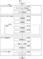
図4は、符号化ストリームTeにおけるデータの階層構造を示す図である。符号化ストリームTeは、例示的に、シーケンス、およびシーケンスを構成する複数のピクチャを含む。図4には、シーケンスSEQを既定する符号化ビデオシーケンス、ピクチャPICTを規定する符号化ピクチャ、スライスSを規定する符号化スライス、スライスデータを規定する符号化スライスデータ、符号化スライスデータに含まれる符号化ツリーユニット、符号化ツリーユニットに含まれる符号化ユニットを示す図が示されている。 FIG. 4 is a diagram showing a hierarchical structure of data in the coded stream Te. The coded stream Te typically includes a sequence and a plurality of pictures that make up the sequence. FIG. 4 includes a coded video sequence that defines the sequence SEQ, a coded picture that defines the picture PICT, a coded slice that defines the slice S, coded slice data that defines the slice data, and coded slice data. A diagram showing a coded tree unit and a coded unit included in the coded tree unit is shown.
(符号化ビデオシーケンス)
符号化ビデオシーケンスでは、処理対象のシーケンスSEQを復号するために動画像復号装置31が参照するデータの集合が規定されている。シーケンスSEQは、図4に示すように、ビデオパラメータセット(Video Parameter Set)、シーケンスパラメータセットSPS(Sequence Parameter Set)、ピクチャパラメータセットPPS(Picture Parameter Set)、Adaptation Parameter Set(APS)、ピクチャPICT、及び、付加拡張情報SEI(Supplemental Enhancement Information)を含んでいる。
(Coded video sequence)
The coded video sequence defines a set of data that the moving
ビデオパラメータセットVPSは、複数のレイヤから構成されている動画像において、複数の動画像に共通する符号化パラメータの集合および動画像に含まれる複数のレイヤおよび個々のレイヤに関連する符号化パラメータの集合が規定されている。 The video parameter set VPS is a set of coding parameters common to a plurality of moving images in a moving image composed of a plurality of layers, and a set of coding parameters related to the plurality of layers included in the moving image and individual layers. The set is defined.
シーケンスパラメータセットSPSでは、対象シーケンスを復号するために動画像復号装置31が参照する符号化パラメータの集合が規定されている。例えば、ピクチャの幅や高さが規定される。なお、SPSは複数存在してもよい。その場合、PPSから複数のSPSの何れかを選択する。
The sequence parameter set SPS defines a set of coding parameters that the moving
ピクチャパラメータセットPPSでは、対象シーケンス内の各ピクチャを復号するために動画像復号装置31が参照する符号化パラメータの集合が規定されている。例えば、ピクチャの復号に用いられる量子化幅の基準値(pic_init_qp_minus26)や重み付き予測の適用を示すフラグ(weighted_pred_flag)が含まれる。なお、PPSは複数存在してもよい。その場合、対象シーケンス内の各ピクチャから複数のPPSの何れかを選択する。
The picture parameter set PPS defines a set of coding parameters that the moving
(符号化ピクチャ)
符号化ピクチャでは、処理対象のピクチャPICTを復号するために動画像復号装置31が参照するデータの集合が規定されている。ピクチャPICTは、図4に示すように、スライス0〜スライスNS-1を含む(NSはピクチャPICTに含まれるスライスの総数)。
(Coded picture)
The coded picture defines a set of data referred to by the moving
なお、以下、スライス0〜スライスNS-1のそれぞれを区別する必要が無い場合、符号の添え字を省略して記述することがある。また、以下に説明する符号化ストリームTeに含まれるデータであって、添え字を付している他のデータについても同様である。
In the following, when it is not necessary to distinguish between
(符号化スライス)
符号化スライスでは、処理対象のスライスSを復号するために動画像復号装置31が参照するデータの集合が規定されている。スライスは、図4に示すように、スライスヘッダ、および、スライスデータを含んでいる。
(Coded slice)
The coded slice defines a set of data referred to by the moving
スライスヘッダには、対象スライスの復号方法を決定するために動画像復号装置31が参照する符号化パラメータ群が含まれる。スライスタイプを指定するスライスタイプ指定情報(slice_type)は、スライスヘッダに含まれる符号化パラメータの一例である。
The slice header contains a group of coding parameters referred to by the moving
スライスタイプ指定情報により指定可能なスライスタイプとしては、(1)符号化の際にイントラ予測のみを用いるIスライス、(2)符号化の際に単方向予測、または、イントラ予測を用いるPスライス、(3)符号化の際に単方向予測、双方向予測、または、イントラ予測を用いるBスライスなどが挙げられる。なお、インター予測は、単予測、双予測に限定されず、より多くの参照ピクチャを用いて予測画像を生成してもよい。以下、P、Bスライスと呼ぶ場合には、インター予測を用いることができるブロックを含むスライスを指す。 The slice types that can be specified by the slice type specification information include (1) I slices that use only intra-prediction during coding, and (2) P-slices that use unidirectional prediction or intra-prediction during coding. (3) B-slice using unidirectional prediction, bidirectional prediction, or intra prediction at the time of coding can be mentioned. Note that the inter-prediction is not limited to single prediction and bi-prediction, and a prediction image may be generated using more reference pictures. Hereinafter, when referred to as P and B slices, they refer to slices containing blocks for which inter-prediction can be used.
なお、スライスヘッダは、ピクチャパラメータセットPPSへの参照(pic_parameter_set_id)を含んでいても良い。 The slice header may include a reference (pic_parameter_set_id) to the picture parameter set PPS.
(符号化スライスデータ)
符号化スライスデータでは、処理対象のスライスデータを復号するために動画像復号装置31が参照するデータの集合が規定されている。スライスデータは、図4の符号化スライスヘッダに示すように、CTUを含んでいる。CTUは、スライスを構成する固定サイズ(例えば64x64)のブロックであり、最大符号化単位(LCU:Largest Coding Unit)と呼ぶこともある。
(Coded slice data)
The coded slice data defines a set of data referred to by the moving
(符号化ツリーユニット)
図4には、処理対象のCTUを復号するために動画像復号装置31が参照するデータの集合が規定されている。CTUは、再帰的な4分木分割(QT(Quad Tree)分割)、2分木分割(BT(Binary Tree)分割)あるいは3分木分割(TT(Ternary Tree)分割)により、符号化処理の基本的な単位である符号化ユニットCUに分割される。BT分割とTT分割を合わせてマルチツリー分割(MT(Multi Tree)分割)と呼ぶ。再帰的な4分木分割により得られる木構造のノードのことを符号化ノード(Coding Node)と称する。4分木、2分木、及び3分木の中間ノードは、符号化ノードであり、CTU自身も最上位の符号化ノードとして規定される。
(Coded tree unit)
FIG. 4 defines a set of data referred to by the moving
CTは、CT情報として、CT分割を行うか否かを示すCU分割フラグ(split_cu_flag)、QT分割を行うか否かを示すQT分割フラグ(qt_split_cu_flag)、MT分割の分割方向を示すMT分割方向(mtt_split_cu_vertical_flag)、MT分割の分割タイプを示すMT分割タイプ(mtt_split_cu_binary_flag)を含む。split_cu_flag、qt_split_cu_flag、mtt_split_cu_vertical_flag、mtt_split_cu_binary_flagは符号化ノード毎に伝送される。 CT has a CU division flag (split_cu_flag) indicating whether or not to perform CT division, a QT division flag (qt_split_cu_flag) indicating whether or not to perform QT division, and an MT division direction (MT division direction) indicating the division direction of MT division as CT information. mtt_split_cu_vertical_flag), MT division type (mtt_split_cu_binary_flag) indicating the division type of MT division is included. split_cu_flag, qt_split_cu_flag, mtt_split_cu_vertical_flag, mtt_split_cu_binary_flag are transmitted for each coding node.
また、CTUのサイズが64x64画素の場合には、CUのサイズは、64x64画素、64x32画素、32x64画素、32x32画素、64x16画素、16x64画素、32x16画素、16x32画素、16x16画素、64x8画素、8x64画素、32x8画素、8x32画素、16x8画素、8x16画素、8x8画素、64x4画素、4x64画素、32x4画素、4x32画素、16x4画素、4x16画素、8x4画素、4x8画素、及び、4x4画素の何れかをとり得る。 If the CTU size is 64x64 pixels, the CU size is 64x64 pixels, 64x32 pixels, 32x64 pixels, 32x32 pixels, 64x16 pixels, 16x64 pixels, 32x16 pixels, 16x32 pixels, 16x16 pixels, 64x8 pixels, 8x64 pixels. , 32x8 pixels, 8x32 pixels, 16x8 pixels, 8x16 pixels, 8x8 pixels, 64x4 pixels, 4x64 pixels, 32x4 pixels, 4x32 pixels, 16x4 pixels, 4x16 pixels, 8x4 pixels, 4x8 pixels, and 4x4 pixels. ..
輝度と色差で異なるツリーを用いても良い。ツリーの種別をtreeTypeで示す。例えば、輝度(Y, cIdx=0)と色差(Cb/Cr, cIdx=1,2)で共通のツリーを用いる場合、共通単一ツリーをtreeType=SINGLE_TREEで示す。輝度と色差で異なる2つのツリー(DUALツリー)を用いる場合、輝度のツリーをtreeType= DUAL_TREE_LUMA、色差のツリーをtreeType=DUAL_TREE_CHROMAで示す。 Trees that differ in brightness and color difference may be used. The tree type is indicated by treeType. For example, when a common tree is used for brightness (Y, cIdx = 0) and color difference (Cb / Cr, cIdx = 1,2), a common single tree is indicated by treeType = SINGLE_TREE. When two trees (DUAL trees) that differ in brightness and color difference are used, the brightness tree is indicated by treeType = DUAL_TREE_LUMA, and the color difference tree is indicated by treeType = DUAL_TREE_CHROMA.
(符号化ユニット)
図4は、処理対象の符号化ユニットを復号するために動画像復号装置31が参照するデータの集合が規定されている。具体的には、CUは、CUヘッダCUH、予測パラメータ、変換パラメータ、量子化変換係数等から構成される。CUヘッダでは予測モード等が規定される。
(Code-coding unit)
FIG. 4 defines a set of data referred to by the moving
予測処理は、CU単位で行われる場合と、CUをさらに分割したサブCU単位で行われる場合がある。CUとサブCUのサイズが等しい場合には、CU中のサブCUは1つである。CUがサブCUのサイズよりも大きい場合、CUはサブCUに分割される。たとえばCUが8x8、サブCUが4x4の場合、CUは水平2分割、垂直2分割からなる、4つのサブCUに分割される。 The prediction process may be performed in CU units or in sub-CU units in which the CU is further divided. If the size of the CU and the sub CU are equal, there is only one sub CU in the CU. If the CU is larger than the size of the sub CU, the CU is split into sub CUs. For example, when the CU is 8x8 and the sub CU is 4x4, the CU is divided into four sub CUs consisting of two horizontal divisions and two vertical divisions.
予測の種類(予測モード)は、イントラ予測と、インター予測の2つがある。イントラ予測は、同一ピクチャ内の予測であり、インター予測は、互いに異なるピクチャ間(例えば、表示時刻間、レイヤ画像間)で行われる予測処理を指す。 There are two types of prediction (prediction mode): intra-prediction and inter-prediction. Intra-prediction is prediction within the same picture, and inter-prediction refers to prediction processing performed between different pictures (for example, between display times and between layer images).
変換・量子化処理はCU単位で行われるが、量子化変換係数は4x4等のサブブロック単位でエントロピー符号化してもよい。 The conversion / quantization process is performed in CU units, but the quantization conversion coefficient may be entropy-encoded in subblock units such as 4x4.
(予測パラメータ)
予測画像は、ブロックに付随する予測パラメータによって導出される。予測パラメータには、イントラ予測とインター予測の予測パラメータがある。
(Prediction parameter)
The prediction image is derived by the prediction parameters associated with the block. Prediction parameters include intra-prediction and inter-prediction prediction parameters.
以下、インター予測の予測パラメータについて説明する。インター予測パラメータは、予測リスト利用フラグpredFlagL0とpredFlagL1、参照ピクチャインデックスrefIdxL0とrefIdxL1、動きベクトルmvL0とmvL1から構成される。predFlagL0、predFlagL1は、参照ピクチャリスト(L0リスト、L1リスト)が用いられるか否かを示すフラグであり、値が1の場合に対応する参照ピクチャリストが用いられる。なお、本明細書中「XXであるか否かを示すフラグ」と記す場合、フラグが0以外(たとえば1)をXXである場合、0をXXではない場合とし、論理否定、論理積などでは1を真、0を偽と扱う(以下同様)。但し、実際の装置や方法では真値、偽値として他の値を用いることもできる。
Hereinafter, the prediction parameters of the inter-prediction will be described. The inter-prediction parameter is composed of the prediction list utilization flags predFlagL0 and predFlagL1, the reference picture indexes refIdxL0 and refIdxL1, and the motion vectors mvL0 and mvL1. predFlagL0 and predFlagL1 are flags indicating whether or not the reference picture list (L0 list, L1 list) is used, and the reference picture list corresponding to the case where the value is 1 is used. In the present specification, when "a flag indicating whether or not it is XX" is described, it is assumed that the flag other than 0 (for example, 1) is XX, 0 is not XX, and logical negation, logical product, etc.
インター予測パラメータを導出するためのシンタックス要素には、例えば、マージモードで用いるアフィンフラグaffine_flag、マージフラグmerge_flag、マージインデックスmerge_idx、MMVDフラグmmvd_flag、AMVPモードで用いる参照ピクチャを選択するためのインター予測識別子inter_pred_idc、参照ピクチャインデックスrefIdxLX、動きベクトルを導出するための予測ベクトルインデックスmvp_LX_idx、差分ベクトルmvdLX、動きベクトル精度モードamvr_modeがある。 The syntax elements for deriving the inter-prediction parameters include, for example, the affine flag affine_flag used in the merge mode, the merge flag merge_flag, the merge index merge_idx, the MMVD flag mmvd_flag, and the inter-prediction identifier for selecting the reference picture used in the AMVP mode. There are inter_pred_idc, reference picture index refIdxLX, prediction vector index mvp_LX_idx for deriving motion vector, difference vector mvdLX, motion vector accuracy mode amvr_mode.
(参照ピクチャリスト)
参照ピクチャリストは、参照ピクチャメモリ306に記憶された参照ピクチャからなるリストである。図5は、参照ピクチャおよび参照ピクチャリストの一例を示す概念図である。図5の参照ピクチャの一例を示す概念図において、矩形はピクチャ、矢印はピクチャの参照関係、横軸は時間、矩形中のI、P、Bは各々イントラピクチャ、単予測ピクチャ、双予測ピクチャ、矩形中の数字は復号順を示す。図に示すように、ピクチャの復号順は、I0、P1、B2、B3、B4であり、表示順は、I0、B3、B2、B4、P1である。図5には、ピクチャB3(対象ピクチャ)の参照ピクチャリストの例を示されている。参照ピクチャリストは、参照ピクチャの候補を表すリストであり、1つのピクチャ(スライス)が1つ以上の参照ピクチャリストを有してもよい。図の例では、対象ピクチャB3は、L0リストRefPicList0およびL1リストRefPicList1の2つの参照ピクチャリストを持つ。個々のCUでは、参照ピクチャリストRefPicListX(X=0または1)中のどのピクチャを実際に参照するかをrefIdxLXで指定する。図は、refIdxL0=2、refIdxL1=0の例である。なお、LXは、L0予測とL1予測を区別しない場合に用いられる記述方法であり、以降では、LXをL0、L1に置き換えることでL0リストに対するパラメータとL1リストに対するパラメータを区別する。
(Reference picture list)
The reference picture list is a list composed of reference pictures stored in the
inter_pred_idcは、参照ピクチャの種類および数を示す値であり、PRED_L0、PRED_L1、PRED_BIの何れかの値をとる。PRED_L0、PRED_L1は、各々L0リスト、L1リストで管理された1枚の参照ピクチャを用いる単予測を示す。PRED_BIはL0リストとL1リストで管理された2枚の参照ピクチャを用いる双予測を示す。 inter_pred_idc is a value indicating the type and number of reference pictures, and takes one of PRED_L0, PRED_L1, and PRED_BI. PRED_L0 and PRED_L1 indicate a simple prediction using one reference picture managed by the L0 list and the L1 list, respectively. PRED_BI shows a bi-prediction using two reference pictures managed by the L0 list and the L1 list.
(動きベクトル)
mvLXは、異なる2つのピクチャ上のブロック間のシフト量を示す。mvLXに関する予測ベクトル、差分ベクトルを、それぞれmvpLX、mvdLXと呼ぶ。
(Motion vector)
mvLX indicates the amount of shift between blocks on two different pictures. The prediction vector and difference vector related to mvLX are called mvpLX and mvdLX, respectively.
(動画像復号装置の構成)
本実施形態に係る動画像復号装置31(図6)の構成について説明する。
(Configuration of moving image decoding device)
The configuration of the moving image decoding device 31 (FIG. 6) according to the present embodiment will be described.
動画像復号装置31は、エントロピー復号部301、パラメータ復号部(予測画像復号装置)302、ループフィルタ305、参照ピクチャメモリ306、予測パラメータメモリ307、予測画像生成部(予測画像生成装置)308、逆量子化・逆変換部311、及び加算部312、予測パラメータ導出部320を含んで構成される。なお、後述の動画像符号化装置11に合わせ、動画像復号装置31にループフィルタ305が含まれない構成もある。
The moving
パラメータ復号部302は、さらに、ヘッダ復号部3020、CT情報復号部3021、及びCU復号部3022(予測モード復号部)を備えており、CU復号部3022はさらにTU復号部3024を備えている。これらを総称して復号モジュールと呼んでもよい。ヘッダ復号部3020は、符号化データからVPS、SPS、PPS、APSなどのパラメータセット情報、スライスヘッダ(スライス情報)を復号する。CT情報復号部3021は、符号化データからCTを復号する。CU復号部3022は符号化データからCUを復号する。TU復号部3024は、TUに予測誤差が含まれている場合に、符号化データからQP更新情報(量子化補正値)と量子化予測誤差(residual_coding)を復号する。
The
TU復号部3024は、スキップモード以外(skip_mode==0)の場合に、符号化データからQP更新情報と量子化予測誤差を復号する。より具体的には、TU復号部3024は、skip_mode==0の場合に、対象ブロックに量子化予測誤差が含まれているか否かを示すフラグcu_cbpを復号し、cu_cbpが1の場合に量子化予測誤差を復号する。cu_cbpが符号化データに存在しない場合は0と導出する。
The
TU復号部3024は、符号化データから変換基底を示すインデックスmts_idxを復号する。また、TU復号部3024は、符号化データからセカンダリ変換の利用及び変換基底を示すインデックスstIdxを復号する。stIdxは0の場合にセカンダリ変換の非適用を示し、1の場合にセカンダリ変換基底のセット(ペア)のうち一方の変換を示し、2の場合に上記ペアのうち他方の変換を示す。
The
また、TU復号部3024はサブブロック変換フラグcu_sbt_flagを復号してもよい。cu_sbt_flagが1の場合には、CUを複数のサブブロックに分割し、特定の1つのサブブロックのみ残差を復号する。さらにTU復号部3024は、サブブロックの数が4であるか2であるかを示すフラグcu_sbt_quad_flag、分割方向を示すcu_sbt_horizontal_flag、非ゼロの変換係数が含まれるサブブロックを示すcu_sbt_pos_flagを復号してもよい。
Further, the
予測画像生成部308は、インター予測画像生成部309及びイントラ予測画像生成部310を含んで構成される。
The prediction
予測パラメータ導出部320は、インター予測パラメータ導出部303及びイントラ予測パラメータ導出部304を含んで構成される。
The prediction
また、以降では処理の単位としてCTU、CUを使用した例を記載するが、この例に限らず、サブCU単位で処理をしてもよい。あるいはCTU、CUをブロック、サブCUをサブブロックと読み替え、ブロックあるいはサブブロック単位の処理としてもよい。 In the following, an example in which CTU and CU are used as the processing unit will be described, but the processing is not limited to this example, and processing may be performed in sub-CU units. Alternatively, CTU and CU may be read as blocks, sub-CUs may be read as sub-blocks, and processing may be performed in units of blocks or sub-blocks.
エントロピー復号部301は、外部から入力された符号化ストリームTeに対してエントロピー復号を行って、個々の符号(シンタックス要素)を復号する。エントロピー符号化には、シンタックス要素の種類や周囲の状況に応じて適応的に選択したコンテキスト(確率モデル)を用いてシンタックス要素を可変長符号化する方式と、あらかじめ定められた表、あるいは計算式を用いてシンタックス要素を可変長符号化する方式がある。前者のCABAC(Context Adaptive Binary Arithmetic Coding)は、コンテキストのCABAC状態(優勢シンボルの種別(0 or 1)と確率を指定する確率状態インデックスpStateIdx)をメモリに格納する。エントロピー復号部301は、セグメント(タイル、CTU行、スライス)の先頭で全てのCABAC状態を初期化する。エントロピー復号部301は、シンタックス要素をバイナリ列(Bin String)に変換し、Bin Stringの各ビットを復号する。コンテキストを用いる場合には、シンタックス要素の各ビットに対してコンテキストインデックスctxIncを導出し、コンテキストを用いてビットを復号し、用いたコンテキストのCABAC状態を更新する。コンテキストを用いないビットは、等確率(EP, bypass)で復号され、ctxInc導出やCABAC状態は省略される。復号されたシンタックス要素には、予測画像を生成するための予測情報および、差分画像を生成するための予測誤差などがある。
The
エントロピー復号部301は、復号した符号をパラメータ復号部302に出力する。復号した符号とは、例えば、予測モードpredMode、merge_flag、merge_idx、inter_pred_idc、refIdxLX、mvp_LX_idx、mvdLX、amvr_mode等である。どの符号を復号するかの制御は、パラメータ復号部302の指示に基づいて行われる。
The
(基本フロー)
図7は、動画像復号装置31の概略的動作を説明するフローチャートである。
(Basic flow)
FIG. 7 is a flowchart illustrating a schematic operation of the moving
(S1100:パラメータセット情報復号)ヘッダ復号部3020は、符号化データからVPS、SPS、PPSなどのパラメータセット情報を復号する。
(S1100: Parameter set information decoding) The
(S1200:スライス情報復号)ヘッダ復号部3020は、符号化データからスライスヘッダ(スライス情報)を復号する。
(S1200: Decoding of slice information) The
以下、動画像復号装置31は、対象ピクチャに含まれる各CTUについて、S1300からS5000の処理を繰り返すことにより各CTUの復号画像を導出する。
Hereinafter, the moving
(S1300:CTU情報復号)CT情報復号部3021は、符号化データからCTUを復号する。
(S1300: CTU information decoding) The CT
(S1400:CT情報復号)CT情報復号部3021は、符号化データからCTを復号する。
(S1400: CT information decoding) The CT
(S1500:CU復号)CU復号部3022はS1510、S1520を実施して、符号化データからCUを復号する。
(S1500: CU decoding) The
(S1510:CU情報復号)CU復号部3022は、符号化データからCU情報、予測情報、TU分割フラグsplit_transform_flag、CU残差フラグcbf_cb、cbf_cr、cbf_luma等を復号する。
(S1510: CU information decoding) The
(S1520:TU情報復号)TU復号部3024は、TUに予測誤差が含まれている場合に、符号化データからQP更新情報と量子化予測誤差、変換インデックスmts_idxを復号する。なお、QP更新情報は、量子化パラメータQPの予測値である量子化パラメータ予測値qPpredからの差分値である。
(S1520: TU information decoding) The
(S2000:予測画像生成)予測画像生成部308は、対象CUに含まれる各ブロックについて、予測情報に基づいて予測画像を生成する。
(S2000: Prediction image generation) The prediction
(S3000:逆量子化・逆変換)逆量子化・逆変換部311は、対象CUに含まれる各TUについて、逆量子化・逆変換処理を実行する。
(S3000: Inverse quantization / inverse conversion) The inverse quantization /
(S4000:復号画像生成)加算部312は、予測画像生成部308より供給される予測画像と、逆量子化・逆変換部311より供給される予測誤差とを加算することによって、対象CUの復号画像を生成する。
(S4000: Decoded image generation) The
(S5000:ループフィルタ)ループフィルタ305は、復号画像にデブロッキングフィルタ、SAO、ALFなどのループフィルタをかけ、復号画像を生成する。
(S5000: Loop filter) The
ループフィルタ305は、符号化ループ内に設けたフィルタで、ブロック歪やリンギング歪を除去し、画質を改善するフィルタである。ループフィルタ305は、加算部312が生成したCUの復号画像に対し、デブロッキングフィルタ、サンプル適応オフセット(SAO)、適応ループフィルタ(ALF)等のフィルタを施す。
The
参照ピクチャメモリ306は、CUの復号画像を、対象ピクチャ及び対象CU毎に予め定めた位置に記憶する。
The
予測パラメータメモリ307は、CTUあるいはCU毎に予め定めた位置に予測パラメータを記憶する。具体的には、予測パラメータメモリ307は、パラメータ復号部302が復号したパラメータ及び予測パラメータ導出部320が導出したパラメータ等を記憶する。
The
予測画像生成部308には予測パラメータ導出部320が導出したパラメータが入力される。また、予測画像生成部308は、参照ピクチャメモリ306から参照ピクチャを読み出す。予測画像生成部308は、predModeが示す予測モードで、パラメータと参照ピクチャ(参照ピクチャブロック)を用いてブロックもしくはサブブロックの予測画像を生成する。ここで、参照ピクチャブロックとは、参照ピクチャ上の画素の集合(通常矩形であるのでブロックと呼ぶ)であり、予測画像を生成するために参照する領域である。
The parameters derived by the prediction
逆量子化・逆変換部311は、パラメータ復号部302から入力された量子化変換係数を逆量子化して変換係数を求める。
The inverse quantization /
逆量子化・逆変換部311は、スケーリング部(逆量子化部)と、セカンダリ変換部と、コア変換部とを備えている。
The inverse quantization /
スケーリング部は、符号化データから復号した量子化マトリックスm[x][y]もしくは一様マトリックスm[x][y]=16と、量子化パラメータqP、TUサイズから導出されるrectNonTsFlagを用いて、スケーリングファクタls[x][y]を導出する。 The scaling part uses the quantization matrix m [x] [y] or uniform matrix m [x] [y] = 16 decoded from the coded data, and the rectNonTsFlag derived from the quantization parameters qP and TU size. , Derivation of the scaling factor ls [x] [y].
ls[x][y] = (m[x][y] * levelScale[rectNonTsFlag][qP%6]) << (qP/6)
ここでlevelScale[] = { { 40, 45, 51, 57, 64, 72 }, { 57, 64, 72, 81, 91, 102 } }である。
ls [x] [y] = (m [x] [y] * levelScale [rectNonTsFlag] [qP% 6]) << (qP / 6)
Where levelScale [] = {{40, 45, 51, 57, 64, 72}, {57, 64, 72, 81, 91, 102}}.
rectNonTsFlag = (((Log2(nTbW) + Log2(nTbH)) & 1) == 1 && transform_skip_flag == 0)
スケーリング部31112は、ls[][]と変換係数TransCoeffLevelの積からdnc[][]を導出し、逆量子化する。さらにクリップによりd[][]を導出する。
rectNonTsFlag = ((((Log2 (nTbW) + Log2 (nTbH)) & 1) == 1 && transform_skip_flag == 0)
The scaling unit 31112 derives dnc [] [] from the product of ls [] [] and the conversion coefficient TransCoeffLevel, and dequantizes it. Furthermore, d [] [] is derived from the clip.
dnc[x][y] = (TransCoeffLevel[xTbY][yTbY][cIdx][x][y] * ls[x][y] + bdOffset) >> bdShift
d[x][y] = Clip3( CoeffMin, CoeffMax, dnc[x][y] )
bdShift = bitDepth + ((rectNonTsFlag ? 1:0) + (Log2(nTbW) + Log2(nTbH)) / 2) - 5 + dep_quant_enabled_flag
bdOffset = ( 1 << bdShift ) >> 1
セカンダリ変換部は、スケーリング部から受信した変換係数d[ ][ ]の一部もしくは全てに対して、変換行列を用いた変換を適用することにより、修正変換係数(第2の変換部による変換後の変換係数)d[ ][ ]を復元する。セカンダリ変換部は、TU毎に所定の単位の変換係数d[ ][ ]に対して セカンダリ変換を適用する。セカンダリ変換は、イントラCUにおいてのみ適用され、変換基底はstIdxとIntraPredModeを参照して決定される。セカンダリ変換部は、復元された修正変換係数d[ ][ ]をコア変換部に出力する。
dnc [x] [y] = (TransCoeffLevel [xTbY] [yTbY] [cIdx] [x] [y] * ls [x] [y] + bdOffset) >> bdShift
d [x] [y] = Clip3 (CoeffMin, CoeffMax, dnc [x] [y])
bdShift = bitDepth + ((rectNonTsFlag? 1: 0) + (Log2 (nTbW) + Log2 (nTbH)) / 2) -5 + dep_quant_enabled_flag
bdOffset = (1 << bdShift) >> 1
The secondary conversion unit applies a conversion using a transformation matrix to a part or all of the conversion coefficients d [] [] received from the scaling unit, thereby performing a correction conversion coefficient (after conversion by the second conversion unit). Conversion coefficient of) d [] [] is restored. The secondary conversion unit applies the secondary conversion to the conversion coefficient d [] [] in a predetermined unit for each TU. The secondary conversion is applied only in the intra CU, and the conversion basis is determined by referring to stIdx and IntraPredMode. The secondary conversion unit outputs the restored correction conversion coefficient d [] [] to the core conversion unit.
コア変換部は、変換係数d[ ][ ]、又は修正変換係数d[ ][ ]を、選択された変換行列を用いて変換し、予測誤差r[][]を導出する。コア変換部は、予測誤差r[][](resSamples[][])を加算部312に出力する。なお、逆量子化・逆変換部311は、skip_flagが1の場合もしくはcu_cbpが0の場合に対象ブロックの予測誤差を全て0と設定する。変換行列はmts_idxにより複数の変換行列から選択してもよい。
The core conversion unit converts the conversion coefficient d [] [] or the modified conversion coefficient d [] [] using the selected transformation matrix, and derives the prediction error r [] []. The core conversion unit outputs the prediction error r [] [] (resSamples [] []) to the
コア変換後の予測誤差d[][]をさらに予測画像Pred[][]と同じ精度になるようにシフトしresSamples[][]を導出してもよい。 The prediction error d [] [] after the core conversion may be further shifted so as to have the same accuracy as the predicted image Pred [] [] to derive resSamples [] [].
resSamples[x][y] = (r[x][y] + (1<<(bdShift-1))) >> bdShift
bdShift = Max( 20 - bitDepth, 0 )
加算部312は、予測画像生成部308から入力されたブロックの予測画像と逆量子化・逆変換部311から入力された予測誤差を画素毎に加算して、ブロックの復号画像を生成する。加算部312はブロックの復号画像を参照ピクチャメモリ306に記憶し、また、ループフィルタ305に出力する。
resSamples [x] [y] = (r [x] [y] + (1 << (bdShift-1))) >> bdShift
bdShift = Max (20 --bitDepth, 0)
The
(動画像変換装置の構成例1)
以下、本実施形態に係る動画像変換装置について説明する。本実施形態に係る動画像変換装置は、画像(ピクチャ、映像)を、解像度を上げて出力する装置である。
(Configuration Example 1 of Moving Image Converter)
Hereinafter, the moving image conversion device according to the present embodiment will be described. The moving image conversion device according to the present embodiment is a device that outputs an image (picture, video) with an increased resolution.
図8は、本例に係る動画像変換装置401の機能ブロック図である。図8に示すように、本例に係る動画像変換装置401は、画像バッファ部403、予測画像生成部405、超解像処理部411および超解像画像バッファ部413を備えている。
FIG. 8 is a functional block diagram of the moving
画像バッファ部403は、複数の低解像度画像を格納する。予測画像生成部405は、動き検出部407および動き補償処理部409を備えている。
The
動き検出部407は、画像バッファ部403から入力された低解像度画像を参照して或る時刻tの動きベクトルを導出する。例えば画像バッファ部403は、時刻t-1,t,t+1の3フレーム分(3ピクチャ分)に対応する画像を格納し、動き検出部407は、そのうち時刻t-1,t+1に対応する画像を参照して時刻tの動きベクトルを導出してもよい。
The
ここで、時刻t-1は、時刻tよりも、画像信号の1フレーム分(1ピクチャ分)に対応する単位時間分だけ過去の時刻を示しており、後述する時刻t+1は、時刻tよりも、上記単位時間分だけ未来の時刻を示している。また、超解像予測画像とは、超解像処理が施された予測画像、又は当該予測画像に相当する画像である。
Here, the time t-1 indicates a time past by a unit time corresponding to one frame (one picture) of the image signal from the time t, and the
動き補償処理部409は、動き検出部407から入力された時刻tにおける動きベクトルと、超解像画像バッファ部413から入力された時刻t-1における超解像画像とを参照して、時刻tにおける超解像予測画像を生成し、超解像処理部411に出力する。
The motion
超解像処理部411は、画像バッファ部403から入力された時刻tにおける画像に対して、動き補償処理部409から入力された時刻tにおける超解像予測画像を参照して超解像処理を施し、時刻tにおける超解像画像を出力する。換言すると、超解像処理部411は、画像バッファ部403から入力された上記時刻tの画像と上記超解像予測画像とを参照して上記超解像画像を出力する。
The
なお、図8に示すように、超解像処理部411は、超解像処理を行う場合に、補助情報を適宜参照してもよい。また、超解像処理部411は、CNN(Convolutional Neural Network)、又はGAN(Generative Adversarial Network)等を用いて学習されたものであってもよい。
As shown in FIG. 8, the
ここで、補助情報とは、画像バッファ部403、超解像処理部411および予測画像生成部405のうち、何れかが参照し得る情報であって、参照元における処理を規定する情報である。
Here, the auxiliary information is information that can be referred to by any one of the
画像バッファ部403は、例えば後述するように、格納する画像の順序を、補助情報を参照して決定してもよい。また、超解像処理部411は、例えば超解像処理後の画像の解像度を、補助情報を参照して決定してもよい。また、予測画像生成部405は、予測画像を生成するか否かを、補助情報を参照して決定してもよい。なお、予測画像を用いない方が良い場合とは、画像信号が示す一連の画像において、場面が急に切り替わり、前後の画像間に類似性が無い場合等である。なお、図8、及び後述する図9等は、超解像処理部411が補助情報を参照する態様を例示している。
The
例えば、補助情報は、超解像処理部411において、画質向上を図るために有用な情報として、対象ピクチャ単位や、対象ピクチャをブロックに分割した時の、ブロック単位の超解像処理のパラメータである。もし、超解像処理をする低解像度の画像の縮小前(元の高解像度)の画像がある場合、例えば二乗誤差のような信号処理的な基準で、高解像度の画像に近づくような超解像処理のパラメータを選択しておくことが可能となる。高解像度の画像に近づける基準に関しては、主観的な要素、例えば、よりエッジを強調するような基準を用いてもよい。或いは、符号化前の画像と符号化、復号後の画像との差分を取り、符号化によって失われた情報を復元する方向で、超解像処理のパラメータを生成することができる。このような超解像処理のパラメータを補助情報とすることで、超解像処理部411において、画質向上を図ることができる。また、もし、低解像度の画像の符号化前の元画像と符号化・復号処理後の画像がある場合は、符号化による誤差と、超解像処理をする低解像度の画像の縮小前の、元の高解像度の画像との誤差の両方を考慮したパラメータを補助情報とすることで、符号化処理が入った場合にも画質向上が図ることができる。
For example, the auxiliary information is a parameter of super-resolution processing for each target picture or when the target picture is divided into blocks as useful information for improving the image quality in the
なお、補助情報は、動画像変換装置401が画像信号とは別途入力する構成でもよいし、画像信号の一部に含まれる構成であってもよい。
The auxiliary information may be input by the moving
超解像画像バッファ部413は、超解像処理部411から入力された複数の超解像画像を格納する。また、超解像画像バッファ部413に格納された複数の超解像画像のうち、時刻t-1における超解像画像が動き補償処理部409に入力される。そして超解像処理部411の出力である、時刻tにおける超解像画像が動画像変換装置401の出力でもあり、例えば再生の対象となる。
The super-resolution
上述したように、本例に係る動画像変換装置401は、複数の画像を格納する画像バッファ部403と、超解像画像バッファ部413に格納された超解像画像を参照して、画像バッファ部403から入力された画像から予測画像を生成する予測画像生成部405と、予測画像を参照して、画像バッファ部403から入力された画像に超解像処理を施す超解像処理部411と、を備えている。上記の構成によれば、超解像処理が施された好適な画像を参照して予測画像を生成可能な動画像変換装置401を実現することができる。
As described above, the moving
また、本例に係る動画像変換装置401によって実行される動画像変換方法は、複数の画像を格納するバッファリングステップと、超解像画像バッファ部413に格納された超解像画像を参照して、前記バッファリングステップにおいて格納されていた画像から予測画像を生成する予測画像生成ステップと、予測画像を参照して、画像バッファ部403から入力された画像に超解像処理を施す超解像処理ステップと、を含んでいる、と言える。上記の方法によれば、超解像処理が施された好適な画像を参照して予測画像を生成できる。
Further, in the moving image conversion method executed by the moving
(動画像変換装置の構成例2)
動画像変換装置の第2の構成例について説明する。本例においては、予測画像生成部405が超解像予測画像を生成する場合に、画像を更に参照する構成について説明する。なお、説明の便宜上、上記の例において既に説明した事項についての重複する記載を繰り返さない。また、以降の例においても同様である。
(Structure example 2 of moving image conversion device)
A second configuration example of the moving image conversion device will be described. In this example, a configuration in which the image is further referred to when the prediction
図9は、本例に係る動画像変換装置401aの機能ブロック図である。図9に示す通り、動画像変換装置401aは、図8に示す構成に加え、アップサンプリング部415を更に備える構成である。
FIG. 9 is a functional block diagram of the moving
アップサンプリング部415は、入力された画像をアップサンプリングすることにより、当該アップサンプリングの前よりも高い解像度の画像を出力する。図9に示す構成において、アップサンプリング部415は、画像バッファ部403から入力された、時刻t+1における低解像度画像に対してアップサンプリングし、動き補償処理部409に出力する。
The
これは、本例に係る動き補償処理部409が、時刻tにおける動きベクトルと、時刻t-1における超解像画像に加え、時刻t+1における、アップサンプリングされた画像を更に参照して、時刻tにおける超解像予測画像を生成することを示している。
This is because the motion
これにより、動き補償処理部409は、時刻t-1における超解像画像と、時刻t+1におけるアップサンプリングされた上記画像との何れか一方に、オクルージョンの問題があったとしても、他方の画像を参照して、好適な超解像予測画像を生成することができる。
As a result, the motion
また、図10は、本例に係る動画像変換装置401aによる処理を示す概念図である。図10においては、時刻t-1,t,t+1における低解像度画像が動き検出部407に順に入力される処理、並びに動き補償処理部409が、時刻tにおける動きベクトル、時刻t-1における超解像画像、及び時刻t+1におけるアップサンプリングされた画像を参照して生成した、時刻tにおける超解像画像を超解像処理部411に出力する処理が図示されている。
Further, FIG. 10 is a conceptual diagram showing processing by the moving
上述したように、本例に係る動画像変換装置401aは、画像バッファ部403から入力された画像をアップサンプリングすることにより、当該アップサンプリングの前よりも解像度が高い画像を出力するアップサンプリング部415を、図8に示す構成から更に備え、予測画像生成部405は、前記時刻t-1の超解像画像と、時刻t+1のアップサンプリングされた画像とを参照して予測画像を生成する構成である。上記の構成によれば、超解像予測画像を生成する処理性能を向上させることができる。
As described above, the moving
(動画像変換装置の構成例3)
動画像変換装置の第3の構成例について説明する。本例においては、動画像変換装置が、画像バッファ部403に格納される画像の順序を変更する構成について説明する。
(Structure example 3 of moving image conversion device)
A third configuration example of the moving image conversion device will be described. In this example, a configuration in which the moving image conversion device changes the order of the images stored in the
図11は、本例に係る動画像変換装置401bの機能ブロック図である。図11に示す通り、動画像変換装置401bは、図8に示す構成に加え、フレーム順序変更部(第1の順序変更部)417およびフレーム逆順序変更部(第2のフレーム順序変更部)419を備えている。
FIG. 11 is a functional block diagram of the moving
フレーム順序変更部417は、低解像度画像の時系列の順序を、所定の順序に変更する。図11に示す構成において、フレーム順序変更部417は、画像バッファ部403において格納される複数の画像の順序を、所定の順序に変更する。具体的には、フレーム順序変更部417は、例えば図11に示すように、時刻tにおける画像と、時刻t-1における画像との順序を入れ替える。これにより、以降で処理対象となる画像の順序は、(t-4,t-3,t-2,t,t-1)=(t’-4,t’-3,t’-2,t’-1,t’)となる。
The frame
なお、フレーム順序変更部417が変更する画像の順序は、補助情報によって規定されてもよい。換言すると、フレーム順序変更部417は、画像の時系列における順序を、補助情報が示す内容に応じて変更してもよい。
The order of the images changed by the frame
フレーム逆順序変更部419は、画像信号が示す画像の時系列における順序を、フレーム順序変更部417が順序を変更する前の、元の順序に変更する。図11に示す構成において、フレーム逆順序変更部419は、超解像画像バッファ部413から入力された超解像画像の順序を、上記元の順序に変更する。
The frame reverse order changing unit 419 changes the order of the images indicated by the image signals in the time series to the original order before the frame
また、図11に示す例において、本例に係る動き検出部407は、順序変更後の過去の4フレームである時刻t’-4,t’-3,t’-2,t’-1に対応する画像を参照して時刻t’の動きベクトルを導出してもよい。
Further, in the example shown in FIG. 11, the
また、本例に係る動き補償処理部409は、時刻t’における超解像予測画像を生成する場合、時刻t’における動きベクトルと、時刻t’-4、t’-3、t’-2、及びt’-1における超解像画像とを参照する構成である。これにより、超解像予測画像を生成する処理性能を向上させることができる。
Further, when the motion
補足すると、時系列における画像の順序がフレーム順序変更部417によって変更されているため、動き補償部が時刻t’(=時刻t−1)における超解像予測画像を生成する場合、時刻t’よりも未来の時刻における時刻t’−1(=時刻t)の超解像画像も参照され得る。したがって、時刻t’よりも過去の時刻における画像と、時刻t’よりも未来の時刻における画像との何れかにオクルージョンの問題があったとしても、他方の画像を参照して、好適な超解像予測画像を生成することができる。また、本例の構成は、画像バッファ部403に入力される画像に許容される遅延が「動画像変換装置の構成例2」の動画像変換装置401aよりも大きい。
Supplementally, since the order of the images in the time series is changed by the frame
上述したように、本例に係る動画像変換装置401bは、画像バッファ部403において格納される複数の画像であって、超解像処理部411に入力される画像の順序を、所定の順序に変更するフレーム順序変更部417と、超解像処理部411が出力した超解像画像の順序を、フレーム順序変更部417が順序を変更する前の順序に変更するフレーム逆順序変更部419とを、図8に示す構成から更に備える構成である。上記の構成によれば、例えば予測画像を生成する場合におけるオクルージョンの問題を回避し易くなる効果を奏する。
As described above, the moving
(動画像変換装置の構成例4)
動画像変換装置の第4の構成例について説明する。本例においては、復号装置が復号した画像が、画像バッファ部403に入力される構成について説明する。
(Structure example 4 of moving image conversion device)
A fourth configuration example of the moving image conversion device will be described. In this example, the configuration in which the image decoded by the decoding device is input to the
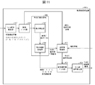
図12は、本例に係る動画像変換装置401cの機能ブロック図である。図12に示す通り、本例に係る動画像変換装置401cは、復号部(復号装置)421、補助情報復号部425および複数フレーム超解像処理部427を備えている。
FIG. 12 is a functional block diagram of the moving image conversion device 401c according to this example. As shown in FIG. 12, the moving image conversion device 401c according to this example includes a decoding unit (decoding device) 421, an auxiliary
復号部421は、動画像復号装置31と同等の機能を有する復号装置である。ただし、図12の例においては、構成が簡略化されており、復号画像は、参照ピクチャメモリ306から、復号部421の外部に出力される構成としている。また、予測部423は、予測画像の生成に関する処理を行う。
The
補助情報復号部425は、符号化された補助情報を復号する。なお、別の態様として、符号化された補助情報は、復号部421が復号する構成でもよいし、補助情報符号化データは符号化ストリームに含まれる構成であってもよい。
The auxiliary
また、補助情報は、参照元における処理を規定する情報であって、複数フレーム超解像処理部427が備える画像バッファ部403、超解像処理部411および予測画像生成部405の何れが参照する情報であってもよい。
Further, the auxiliary information is information that defines processing at the reference source, and is referred to by any of the
複数フレーム超解像処理部427は、図8(或いは図9又は図11)に示す動画像変換装置401(或いは401a又は401b)を簡略化して示したものであって、動画像変換装置401等と同等の機能を有し、画像バッファ部403等を備える。
The multi-frame
上述した構成を別の側面から言えば、本例に係る動画像変換装置401cは、画像の符号化ストリームを復号する復号部421を、図8等に示す構成から更に備え、復号部421が復号した画像を、複数フレーム超解像処理部427が備える画像バッファ部403に対する入力画像とする構成である、と言える。上記の構成によれば、符号化ストリームを処理対象とする動画像変換装置401cを実現できる。
Speaking of the above configuration from another aspect, the moving image conversion device 401c according to this example further includes a
また、本例に係る動画像変換装置401cは、画像バッファ部403、超解像処理部411および予測画像生成部405のうち、少なくとも何れかが参照する補助情報であって、参照元における処理を規定する補助情報を復号する補助情報復号部425を、図8等に示す構成から更に備える構成である。上記の構成によれば、符号化された補助情報を復号して参照可能な動画像変換装置401cを実現できる。
Further, the moving image conversion device 401c according to this example is auxiliary information referred to by at least one of the
なお、本例の別の態様として、復号部(復号装置)421及び補助情報復号部425は、動画像変換装置401cが備えるものではなく、外部の装置として実現される構成であってもよい。また、復号部421が備える参照ピクチャメモリ306と、複数フレーム超解像処理部427が備える画像バッファ部403とは、共通した単一のメモリであってもよい。
As another aspect of this example, the decoding unit (decoding device) 421 and the auxiliary
(動画像変換装置の構成例5)
動画像変換装置の第5の構成例について説明する。本例においては、動画像変換装置が、復号された画像に対する処理を、補助情報に応じて切り替える構成について説明する。
(Structure example 5 of moving image conversion device)
A fifth configuration example of the moving image conversion device will be described. In this example, a configuration in which the moving image conversion device switches the processing for the decoded image according to the auxiliary information will be described.
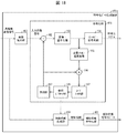
図13は、本例に係る動画像変換装置401dの機能ブロック図である。図13に示す通り、本例に係る動画像変換装置401dは、切替部429、フレーム内超解像処理部431およびアップサンプリング部433を、図12に示す構成からさらに備える。
FIG. 13 is a functional block diagram of the moving image conversion device 401d according to this example. As shown in FIG. 13, the moving image conversion device 401d according to this example further includes a switching unit 429, an in-frame
切替部429は、復号部421から出力された復号画像の出力先を、補助情報を参照して、複数フレーム超解像処理部427、フレーム内超解像処理部431およびアップサンプリング部433の何れかに切り替える。即ち、本例において補助情報とは、切替部429の処理を規定する情報である。フレーム内超解像処理部431は、処理対象となる画像自体を参照して、当該画像に対して超解像処理を施す。アップサンプリング部433は、入力された画像をアップサンプリングすることにより、当該アップサンプリングの前よりも高い解像度の画像を出力する。
The switching unit 429 refers to the output destination of the decoded image output from the
尚、切替の単位は、GOP(Group of Picture)と呼ばれるようなアクセス可能な複数のピクチャ単位や、1ピクチャ単位や、1ピクチャを分割したブロック単位で可能である。 The unit of switching can be a plurality of accessible picture units such as GOP (Group of Pictures), one picture unit, or a block unit in which one picture is divided.
上述した構成を別の側面から言えば、本例に係る動画像変換装置401dは、画像の符号化ストリームを復号する復号部421、復号部421が復号した画像の出力先を切り替える切替部429、および切替部429の処理を規定する補助情報を復号する補助情報復号部425等を、図12等に示す構成から更に備え、切替部429が前記補助情報を参照して切り替える前記復号した画像の出力先の1つが、複数フレーム超解像処理部427が備える画像バッファ部403である構成である、と言える。上記の構成によれば、符号化ストリームを処理対象とし、必要に応じて超解像処理が施された画像を出力可能な動画像変換装置401dを実現することができる。
Speaking of the above configuration from another aspect, the moving image conversion device 401d according to this example includes a
(動画像符号化装置の構成)
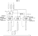
次に、本実施形態に係る動画像符号化装置11の構成について説明する。図14は、本実施形態に係る動画像符号化装置11の構成を示すブロック図である。動画像符号化装置11は、予測画像生成部101、減算部102、変換・量子化部103、逆量子化・逆変換部105、加算部106、ループフィルタ107、予測パラメータメモリ(予測パラメータ記憶部、フレームメモリ)108、参照ピクチャメモリ(参照画像記憶部、フレームメモリ)109、符号化パラメータ決定部110、パラメータ符号化部111、予測パラメータ導出部120、エントロピー符号化部104を含んで構成される。
(Configuration of moving image coding device)
Next, the configuration of the moving
予測画像生成部101はCU毎に予測画像を生成する。予測画像生成部101は既に説明したインター予測画像生成部309とイントラ予測画像生成部310を含んでおり、説明を省略する。
The prediction
減算部102は、予測画像生成部101から入力されたブロックの予測画像の画素値を、画像Tの画素値から減算して予測誤差を生成する。減算部102は予測誤差を変換・量子化部103に出力する。
The
変換・量子化部103は、減算部102から入力された予測誤差に対し、周波数変換によって変換係数を算出し、量子化によって量子化変換係数を導出する。変換・量子化部103は、量子化変換係数をパラメータ符号化部111及び逆量子化・逆変換部105に出力する。
The conversion /
逆量子化・逆変換部105は、動画像復号装置31における逆量子化・逆変換部311(図6)と同じであり、説明を省略する。算出した予測誤差は加算部106に出力される。
The inverse quantization /
パラメータ符号化部111は、ヘッダ符号化部1110、CT情報符号化部1111、CU符号化部1112(予測モード符号化部)を備えている。CU符号化部1112はさらにTU符号化部1114を備えている。以下、各モジュールの概略動作を説明する。
The
ヘッダ符号化部1110はヘッダ情報、分割情報、予測情報、量子化変換係数等のパラメータの符号化処理を行う。
The
CT情報符号化部1111は、QT、MT(BT、TT)分割情報等を符号化する。 The CT information coding unit 1111 encodes QT, MT (BT, TT) division information and the like.
CU符号化部1112はCU情報、予測情報、分割情報等を符号化する。 The CU coding unit 1112 encodes CU information, prediction information, division information, and the like.
TU符号化部1114は、TUに予測誤差が含まれている場合に、QP更新情報と量子化予測誤差を符号化する。
The
CT情報符号化部1111、CU符号化部1112は、インター予測パラメータ(predMode、merge_flag、merge_idx、inter_pred_idc、refIdxLX、mvp_LX_idx、mvdLX)、イントラ予測パラメータ(intra_luma_mpm_flag、intra_luma_mpm_idx、intra_luma_mpm_reminder、intra_chroma_pred_mode)、量子化変換係数等のシンタックス要素をパラメータ符号化部111に供給する。
CT information coding unit 1111 and CU coding unit 1112 have inter-prediction parameters (predMode, merge_flag, merge_idx, inter_pred_idc, refIdxLX, mvp_LX_idx, mvdLX), intra-prediction parameters (intra_luma_mpm_flag, intra_luma_mpm_idx, intra_luma_mpm_idx, intra_luma) Etc. are supplied to the
エントロピー符号化部104には、パラメータ符号化部111から量子化変換係数と符号化パラメータ(分割情報、予測パラメータ)が入力される。エントロピー符号化部104はこれらをエントロピー符号化して符号化ストリームTeを生成し、出力する。
The quantization conversion coefficient and coding parameters (division information, prediction parameters) are input to the
予測パラメータ導出部120は、インター予測パラメータ符号化部112、イントラ予測パラメータ符号化部113を含む手段であり、符号化パラメータ決定部110から入力されたパラメータからイントラ予測パラメータ及びイントラ予測パラメータを導出する。導出されたイントラ予測パラメータ及びイントラ予測パラメータは、パラメータ符号化部111に出力される。
The prediction
加算部106は、予測画像生成部101から入力された予測ブロックの画素値と逆量子化・逆変換部105から入力された予測誤差を画素毎に加算して復号画像を生成する。加算部106は生成した復号画像を参照ピクチャメモリ109に記憶する。
The
ループフィルタ107は加算部106が生成した復号画像に対し、デブロッキングフィルタ、SAO、ALFを施す。なお、ループフィルタ107は、必ずしも上記3種類のフィルタを含まなくてもよく、例えばデブロッキングフィルタのみの構成であってもよい。
The
予測パラメータメモリ108は、符号化パラメータ決定部110が生成した予測パラメータを、対象ピクチャ及びCU毎に予め定めた位置に記憶する。
The prediction parameter memory 108 stores the prediction parameters generated by the coding
参照ピクチャメモリ109は、ループフィルタ107が生成した復号画像を対象ピクチャ及びCU毎に予め定めた位置に記憶する。
The
符号化パラメータ決定部110は、符号化パラメータの複数のセットのうち、1つのセットを選択する。符号化パラメータとは、上述したQT、BTあるいはTT分割情報、予測パラメータ、あるいはこれらに関連して生成される符号化の対象となるパラメータである。予測画像生成部101は、これらの符号化パラメータを用いて予測画像を生成する。
The coding
符号化パラメータ決定部110は、複数のセットの各々について情報量の大きさと符号化誤差を示すRDコスト値を算出する。RDコスト値は、例えば、符号量と二乗誤差に係数λを乗じた値との和である。符号量は、量子化誤差と符号化パラメータをエントロピー符号化して得られる符号化ストリームTeの情報量である。二乗誤差は、減算部102において算出された予測誤差の二乗和である。係数λは、予め設定されたゼロよりも大きい実数である。符号化パラメータ決定部110は、算出したコスト値が最小となる符号化パラメータのセットを選択する。符号化パラメータ決定部110は決定した符号化パラメータをパラメータ符号化部111と予測パラメータ導出部120に出力する。
The coding
(符号化データ生成装置の構成例1)
以下、本実施形態に係る符号化データ生成装置について説明する。符号化データ生成装置は、画像の符号化ストリーム、および補助情報符号化データをそれぞれ出力する装置である。本例においては「動画像変換装置の構成例4」において上述した動画像変換装置401c等と対として用いられる符号化データ生成装置451cについて説明する。
(Configuration Example 1 of Coded Data Generator)
Hereinafter, the coded data generation device according to the present embodiment will be described. The coded data generation device is a device that outputs a coded stream of an image and auxiliary information coded data, respectively. In this example, the coded data generation device 451c used as a pair with the above-mentioned moving image conversion device 401c or the like in "Structure example 4 of the moving image conversion device" will be described.
図15は、本例に係る符号化データ生成装置451cの機能ブロック図である。図15に示す通り、本例に係る符号化データ生成装置451cは、画像縮小部(ダウンサンプリング部)453、符号化部(符号化装置)455、および補助情報符号化部461を備えている。
FIG. 15 is a functional block diagram of the coded data generation device 451c according to this example. As shown in FIG. 15, the coded data generation device 451c according to this example includes an image reduction unit (downsampling unit) 453, a coding unit (coding device) 455, and an auxiliary
画像縮小部453は、入力された画像をダウンサンプリングすることにより、当該ダウンサンプリングの前よりも低い解像度の画像を出力する。
By downsampling the input image, the
符号化部455は、符号化装置11と同等の機能を有する符号化装置である。ただし、図15の例においては、構成が簡略化されている。
The
補助情報符号化部461は、動画像変換装置の処理を規定する補助情報を符号化する。本例に係る補助情報符号化部461は、画像縮小部453から入力された情報であって、画像の縮小率を示す情報を、補助情報として符号化する。別の側面から言えば、画像縮小部453は、画像の縮小率を示す補助情報を生成する補助情報生成部としても機能すると言える。なお、当該情報は、例えば動画像変換装置401cが備える超解像処理部411が、出力する超解像画像の解像度を決定する場合に参照してもよい。
The auxiliary
本例に係る符号化データ生成装置451cは、動画像変換装置401c(或いは401、401a又は401b)によって参照される補助情報を生成する補助情報生成部(上記の例では画像縮小部453)を備えている。当該補助情報は、画像バッファ部403、超解像処理部411および予測画像生成部405のうち、少なくとも何れかが参照する補助情報であってもよい。上記の構成によれば、動画像変換装置401c等と対として用いられる符号化データ生成装置451cを実現できる。
The coded data generation device 451c according to this example includes an auxiliary information generation unit (
なお、符号化された補助情報が、画像の符号化ストリームに含まれる構成であってもよい。上記の構成の場合、例えばエントロピー符号化部104が、補助情報符号化データと符号化ストリームとを合成する構成であってもよいし、エントロピー符号化部104が補助情報符号化部461として機能する構成であってもよい。
The coded auxiliary information may be included in the coded stream of the image. In the case of the above configuration, for example, the
(符号化データ生成装置の構成例2)
符号化データ生成装置の第2の構成例について説明する。本例においては「動画像変換装置の構成例5」において上述した動画像変換装置401dと対として用いられる符号化データ生成装置451dについて説明する。なお、説明の便宜上、上記の例において既に説明した事項についての重複する記載を繰り返さない。
(Configuration Example 2 of Coded Data Generator)
A second configuration example of the coded data generator will be described. In this example, the coded
図16は、本例に係る符号化データ生成装置451dの機能ブロック図である。図16に示す通り、本例に係る符号化データ生成装置451dは、符号化部(符号化装置)455、画像縮小部453、補助情報生成部459および補助情報符号化部461を備えている。
FIG. 16 is a functional block diagram of the coded
補助情報生成部459は、符号化データ生成装置451dへの入力画像と、参照ピクチャメモリ109に格納された復号画像とを参照して、補助情報を生成してもよい。本例において補助情報とは、動画像変換装置401dの切替部429が、復号画像の出力先を切り替える場合に参照する情報であってもよい。補助情報生成部459が生成した補助情報は、補助情報符号化部461に入力されて符号化される。
The auxiliary
上記の構成によれば、動画像変換装置401dと対として用いられる符号化データ生成装置451dを実現できる。
According to the above configuration, the coded
(符号化データ生成装置の構成例3)
符号化データ生成装置の第3の構成例について説明する。本例においては「動画像変換装置の構成例4」において上述した動画像変換装置401c、もしくは図17に示す動画像変換装置401eと対として用いられる符号化データ生成装置451eについて説明する。動画像変換装置401eは、動画像変換装置401cにおける複数フレーム超解像処理部427のかわりにフレーム内超解像処理部431を備えた構成である。フレーム内超解像処理部431は、処理対象となる画像自体を参照して、当該画像に対して超解像処理を施す。なお、説明の便宜上、上記の例において既に説明した事項についての重複する記載を繰り返さない。
(Configuration Example 3 of Coded Data Generator)
A third configuration example of the coded data generator will be described. In this example, the above-mentioned moving image conversion device 401c or the coded
図18は、本例に係る符号化データ生成装置451eの機能ブロック図である。図18に示す通り、本例に係る符号化データ生成装置451eは、符号化部(符号化装置)455、画像縮小部453、補助情報生成部459および補助情報符号化部461を備えている。
FIG. 18 is a functional block diagram of the coded
補助情報生成部459は、符号化データ生成装置451eへの入力である高解像画像信号に対して、周波数特性を元にした複雑度情報から補助情報を生成する。複雑度情報は、画像分散やエッジ抽出によって導出してもよい。補助情報生成部459は、参照ピクチャメモリ109に格納された復号画像に対しても同様の複雑度情報の導出を行い、複雑度情報と比較を行うことで補助情報を生成してもよい。補助情報生成部459は、画素単位に補助情報を生成してもよいし、補助情報の情報量を抑制するためブロック単位に補助情報を生成してもよい。補助情報生成部459は、補助情報の情報量を抑制するため量子化処理を行ってもよい。補助情報生成部459が生成した補助情報は、補助情報符号化部461に入力されて符号化される。
The auxiliary
なお、上述した実施形態における動画像符号化装置11、動画像復号装置31の一部、例えば、エントロピー復号部301、パラメータ復号部302、ループフィルタ305、予測画像生成部308、逆量子化・逆変換部311、加算部312、予測パラメータ導出部320、予測画像生成部101、減算部102、変換・量子化部103、エントロピー符号化部104、逆量子化・逆変換部105、ループフィルタ107、符号化パラメータ決定部110、パラメータ符号化部111、予測パラメータ導出部120をコンピュータで実現するようにしても良い。その場合、この制御機能を実現するためのプログラムをコンピュータ読み取り可能な記録媒体に記録して、この記録媒体に記録されたプログラムをコンピュータシステムに読み込ませ、実行することによって実現しても良い。なお、ここでいう「コンピュータシステム」とは、動画像符号化装置11、動画像復号装置31のいずれかに内蔵されたコンピュータシステムであって、OSや周辺機器等のハードウェアを含むものとする。また、「コンピュータ読み取り可能な記録媒体」とは、フレキシブルディスク、光磁気ディスク、ROM、CD-ROM等の可搬媒体、コンピュータシステムに内蔵されるハードディスク等の記憶装置のことをいう。さらに「コンピュータ読み取り可能な記録媒体」とは、インターネット等のネットワークや電話回線等の通信回線を介してプログラムを送信する場合の通信線のように、短時間、動的にプログラムを保持するもの、その場合のサーバやクライアントとなるコンピュータシステム内部の揮発性メモリのように、一定時間プログラムを保持しているものも含んでも良い。また上記プログラムは、前述した機能の一部を実現するためのものであっても良く、さらに前述した機能をコンピュータシステムにすでに記録されているプログラムとの組み合わせで実現できるものであっても良い。
A part of the moving
また、上述した実施形態における動画像符号化装置11、動画像復号装置31の一部、または全部を、LSI(Large Scale Integration)等の集積回路として実現しても良い。動画像符号化装置11、動画像復号装置31の各機能ブロックは個別にプロセッサ化しても良いし、一部、または全部を集積してプロセッサ化しても良い。また、集積回路化の手法はLSIに限らず専用回路、または汎用プロセッサで実現しても良い。また、半導体技術の進歩によりLSIに代替する集積回路化の技術が出現した場合、当該技術による集積回路を用いても良い。
Further, a part or all of the moving
以上、図面を参照してこの発明の一実施形態について詳しく説明してきたが、具体的な構成は上述のものに限られることはなく、この発明の要旨を逸脱しない範囲内において様々な設計変更等をすることが可能である。 Although one embodiment of the present invention has been described in detail with reference to the drawings, the specific configuration is not limited to the above, and various design changes and the like are made without departing from the gist of the present invention. It is possible to do.
〔応用例〕
上述した動画像符号化装置11及び動画像復号装置31は、動画像の送信、受信、記録、再生を行う各種装置に搭載して利用することができる。なお、動画像は、カメラ等により撮像された自然動画像であってもよいし、コンピュータ等により生成された人工動画像(CGおよびGUIを含む)であってもよい。
[Application example]
The moving
まず、上述した動画像符号化装置11及び動画像復号装置31を、動画像の送信及び受信に利用できることを、図2を参照して説明する。
First, it will be described with reference to FIG. 2 that the moving
図2のPROD_Aは、動画像符号化装置11を搭載した送信装置PROD_Aの構成を示したブロック図である。図に示すように、送信装置PROD_Aは、動画像を符号化することによって符号化データを得る符号化部PROD_A1と、符号化部PROD_A1が得た符号化データで搬送波を変調することによって変調信号を得る変調部PROD_A2と、変調部PROD_A2が得た変調信号を送信する送信部PROD_A3と、を備えている。上述した動画像符号化装置11は、この符号化部PROD_A1として利用される。
PROD_A in FIG. 2 is a block diagram showing a configuration of a transmission device PROD_A equipped with a moving
送信装置PROD_Aは、符号化部PROD_A1に入力する動画像の供給源として、動画像を撮像するカメラPROD_A4、動画像を記録した記録媒体PROD_A5、動画像を外部から入力するための入力端子PROD_A6、及び、画像を生成または加工する画像処理部A7を更に備えていてもよい。図においては、これら全てを送信装置PROD_Aが備えた構成を例示しているが、一部を省略しても構わない。 The transmitter PROD_A has a camera PROD_A4 for capturing a moving image, a recording medium PROD_A5 for recording a moving image, an input terminal PROD_A6 for inputting a moving image from the outside, and a moving image as a source of the moving image to be input to the coding unit PROD_A1. , An image processing unit A7 for generating or processing an image may be further provided. In the figure, the configuration in which the transmitter PROD_A is provided with all of these is illustrated, but some of them may be omitted.
なお、記録媒体PROD_A5は、符号化されていない動画像を記録したものであってもよいし、伝送用の符号化方式とは異なる記録用の符号化方式で符号化された動画像を記録したものであってもよい。後者の場合、記録媒体PROD_A5と符号化部PROD_A1との間に、記録媒体PROD_A5から読み出した符号化データを記録用の符号化方式に従って復号する復号部(不図示)を介在させるとよい。 The recording medium PROD_A5 may be a recording of an unencoded moving image, or a moving image encoded by a recording coding method different from the transmission coding method. It may be a thing. In the latter case, a decoding unit (not shown) that decodes the coded data read from the recording medium PROD_A5 according to the coding method for recording may be interposed between the recording medium PROD_A5 and the coding unit PROD_A1.
図2のPROD_Bは、動画像復号装置31を搭載した受信装置PROD_Bの構成を示したブロック図である。図に示すように、受信装置PROD_Bは、変調信号を受信する受信部PROD_B1と、受信部PROD_B1が受信した変調信号を復調することによって符号化データを得る復調部PROD_B2と、復調部PROD_B2が得た符号化データを復号することによって動画像を得る復号部PROD_B3と、を備えている。上述した動画像復号装置31は、この復号部PROD_B3として利用される。
PROD_B in FIG. 2 is a block diagram showing a configuration of a receiving device PROD_B equipped with a moving
受信装置PROD_Bは、復号部PROD_B3が出力する動画像の供給先として、動画像を表示するディスプレイPROD_B4、動画像を記録するための記録媒体PROD_B5、及び、動画像を外部に出力するための出力端子PROD_B6を更に備えていてもよい。図においては、これら全てを受信装置PROD_Bが備えた構成を例示しているが、一部を省略しても構わない。 The receiving device PROD_B serves as a supply destination of the moving image output by the decoding unit PROD_B3, a display PROD_B4 for displaying the moving image, a recording medium PROD_B5 for recording the moving image, and an output terminal for outputting the moving image to the outside. It may also have PROD_B6. In the figure, the configuration in which the receiving device PROD_B is provided with all of these is illustrated, but some of them may be omitted.
なお、記録媒体PROD_B5は、符号化されていない動画像を記録するためのものであってもよいし、伝送用の符号化方式とは異なる記録用の符号化方式で符号化されたものであってもよい。後者の場合、復号部PROD_B3と記録媒体PROD_B5との間に、復号部PROD_B3から取得した動画像を記録用の符号化方式に従って符号化する符号化部(不図示)を介在させるとよい。 The recording medium PROD_B5 may be used for recording an unencoded moving image, or may be encoded by a recording coding method different from the transmission coding method. You may. In the latter case, a coding unit (not shown) that encodes the moving image acquired from the decoding unit PROD_B3 according to the recording coding method may be interposed between the decoding unit PROD_B3 and the recording medium PROD_B5.
なお、変調信号を伝送する伝送媒体は、無線であってもよいし、有線であってもよい。また、変調信号を伝送する伝送態様は、放送(ここでは、送信先が予め特定されていない送信態様を指す)であってもよいし、通信(ここでは、送信先が予め特定されている送信態様を指す)であってもよい。すなわち、変調信号の伝送は、無線放送、有線放送、無線通信、及び有線通信の何れによって実現してもよい。 The transmission medium for transmitting the modulated signal may be wireless or wired. Further, the transmission mode for transmitting the modulated signal may be broadcasting (here, a transmission mode in which the destination is not specified in advance) or communication (here, transmission in which the destination is specified in advance). Refers to an aspect). That is, the transmission of the modulated signal may be realized by any of wireless broadcasting, wired broadcasting, wireless communication, and wired communication.
例えば、地上デジタル放送の放送局(放送設備など)/受信局(テレビジョン受像機など)は、変調信号を無線放送で送受信する送信装置PROD_A/受信装置PROD_Bの一例である。また、ケーブルテレビ放送の放送局(放送設備など)/受信局(テレビジョン受像機など)は、変調信号を有線放送で送受信する送信装置PROD_A/受信装置PROD_Bの一例である。 For example, a broadcasting station (broadcasting equipment, etc.) / receiving station (television receiver, etc.) of terrestrial digital broadcasting is an example of a transmitting device PROD_A / receiving device PROD_B that transmits and receives modulated signals by radio broadcasting. Further, a broadcasting station (broadcasting equipment, etc.) / receiving station (television receiver, etc.) of cable television broadcasting is an example of a transmitting device PROD_A / receiving device PROD_B that transmits and receives modulated signals by wired broadcasting.
また、インターネットを用いたVOD(Video On Demand)サービスや動画共有サービスなどのサーバ(ワークステーションなど)/クライアント(テレビジョン受像機、パーソナルコンピュータ、スマートフォンなど)は、変調信号を通信で送受信する送信装置PROD_A/受信装置PROD_Bの一例である(通常、LANにおいては伝送媒体として無線または有線の何れかが用いられ、WANにおいては伝送媒体として有線が用いられる)。ここで、パーソナルコンピュータには、デスクトップ型PC、ラップトップ型PC、及びタブレット型PCが含まれる。また、スマートフォンには、多機能携帯電話端末も含まれる。 In addition, servers (workstations, etc.) / clients (television receivers, personal computers, smartphones, etc.) for VOD (Video On Demand) services and video sharing services using the Internet are transmitters that send and receive modulated signals via communication. This is an example of PROD_A / receiver PROD_B (usually, in LAN, either wireless or wired is used as a transmission medium, and in WAN, wired is used as a transmission medium). Here, personal computers include desktop PCs, laptop PCs, and tablet PCs. Smartphones also include multifunctional mobile phone terminals.
なお、動画共有サービスのクライアントは、サーバからダウンロードした符号化データを復号してディスプレイに表示する機能に加え、カメラで撮像した動画像を符号化してサーバにアップロードする機能を有している。すなわち、動画共有サービスのクライアントは、送信装置PROD_A及び受信装置PROD_Bの双方として機能する。 The client of the video sharing service has a function of decoding the encoded data downloaded from the server and displaying it on the display, as well as a function of encoding the moving image captured by the camera and uploading it to the server. That is, the client of the video sharing service functions as both the transmitting device PROD_A and the receiving device PROD_B.
次に、上述した動画像符号化装置11及び動画像復号装置31を、動画像の記録及び再生に利用できることを、図3を参照して説明する。
Next, it will be described with reference to FIG. 3 that the moving
図3のPROD_Cは、上述した動画像符号化装置11を搭載した記録装置PROD_Cの構成を示したブロック図である。図に示すように、記録装置PROD_Cは、動画像を符号化することによって符号化データを得る符号化部PROD_C1と、符号化部PROD_C1が得た符号化データを記録媒体PROD_Mに書き込む書込部PROD_C2と、を備えている。上述した動画像符号化装置11は、この符号化部PROD_C1として利用される。
PROD_C in FIG. 3 is a block diagram showing a configuration of a recording device PROD_C equipped with the above-mentioned moving
なお、記録媒体PROD_Mは、(1)HDD(Hard Disk Drive)やSSD(Solid State Drive)などのように、記録装置PROD_Cに内蔵されるタイプのものであってもよいし、(2)SDメモリカードやUSB(Universal Serial Bus)フラッシュメモリなどのように、記録装置PROD_Cに接続されるタイプのものであってもよいし、(3)DVD(Digital Versatile Disc:登録商標)やBD(Blu-ray Disc:登録商標)などのように、記録装置PROD_Cに内蔵されたドライブ装置(不図示)に装填されるものであってもよい。 The recording medium PROD_M may be of a type built in the recording device PROD_C, such as (1) HDD (Hard Disk Drive) or SSD (Solid State Drive), or (2) SD memory. It may be a type that is connected to the recording device PROD_C, such as a card or USB (Universal Serial Bus) flash memory, and (3) DVD (Digital Versatile Disc: registered trademark) or BD (Blu-ray). It may be loaded in a drive device (not shown) built in the recording device PROD_C, such as Disc (registered trademark).
また、記録装置PROD_Cは、符号化部PROD_C1に入力する動画像の供給源として、動画像を撮像するカメラPROD_C3、動画像を外部から入力するための入力端子PROD_C4、動画像を受信するための受信部PROD_C5、及び、画像を生成または加工する画像処理部PROD_C6を更に備えていてもよい。図においては、これら全てを記録装置PROD_Cが備えた構成を例示しているが、一部を省略しても構わない。 Further, the recording device PROD_C has a camera PROD_C3 that captures a moving image, an input terminal PROD_C4 for inputting a moving image from the outside, and a reception for receiving the moving image as a source of the moving image to be input to the coding unit PROD_C1. The unit PROD_C5 and the image processing unit PROD_C6 for generating or processing an image may be further provided. In the figure, the configuration in which the recording device PROD_C is provided with all of these is illustrated, but some of them may be omitted.
なお、受信部PROD_C5は、符号化されていない動画像を受信するものであってもよいし、記録用の符号化方式とは異なる伝送用の符号化方式で符号化された符号化データを受信するものであってもよい。後者の場合、受信部PROD_C5と符号化部PROD_C1との間に、伝送用の符号化方式で符号化された符号化データを復号する伝送用復号部(不図示)を介在させるとよい。 The receiving unit PROD_C5 may receive an unencoded moving image, or receives coded data encoded by a transmission coding method different from the recording coding method. It may be something to do. In the latter case, it is preferable to interpose a transmission decoding unit (not shown) for decoding the coded data encoded by the transmission coding method between the receiving unit PROD_C5 and the coding unit PROD_C1.
このような記録装置PROD_Cとしては、例えば、DVDレコーダ、BDレコーダ、HDD(Hard Disk Drive)レコーダなどが挙げられる(この場合、入力端子PROD_C4または受信部PROD_C5が動画像の主な供給源となる)。また、カムコーダ(この場合、カメラPROD_C3が動画像の主な供給源となる)、パーソナルコンピュータ(この場合、受信部PROD_C5または画像処理部C6が動画像の主な供給源となる)、スマートフォン(この場合、カメラPROD_C3または受信部PROD_C5が動画像の主な供給源となる)なども、このような記録装置PROD_Cの一例である。 Examples of such a recording device PROD_C include a DVD recorder, a BD recorder, an HDD (Hard Disk Drive) recorder, and the like (in this case, the input terminal PROD_C4 or the receiving unit PROD_C5 is the main source of moving images). .. In addition, a camcorder (in this case, the camera PROD_C3 is the main source of moving images), a personal computer (in this case, the receiving unit PROD_C5 or the image processing unit C6 is the main source of moving images), and a smartphone (this In this case, the camera PROD_C3 or the receiver PROD_C5 is the main source of moving images) is also an example of such a recording device PROD_C.
図3PROD_Dは、上述した動画像復号装置31を搭載した再生装置PROD_Dの構成を示したブロックである。図に示すように、再生装置PROD_Dは、記録媒体PROD_Mに書き込まれた符号化データを読み出す読出部PROD_D1と、読出部PROD_D1が読み出した符号化データを復号することによって動画像を得る復号部PROD_D2と、を備えている。上述した動画像復号装置31は、この復号部PROD_D2として利用される。
FIG. 3 PROD_D is a block showing the configuration of the playback device PROD_D equipped with the above-mentioned moving
なお、記録媒体PROD_Mは、(1)HDDやSSDなどのように、再生装置PROD_Dに内蔵されるタイプのものであってもよいし、(2)SDメモリカードやUSBフラッシュメモリなどのように、再生装置PROD_Dに接続されるタイプのものであってもよいし、(3)DVDやBDなどのように、再生装置PROD_Dに内蔵されたドライブ装置(不図示)に装填されるものであってもよい。 The recording medium PROD_M may be of a type built into the playback device PROD_D, such as (1) HDD or SSD, or (2) such as an SD memory card or USB flash memory. It may be of a type connected to the playback device PROD_D, or may be loaded into a drive device (not shown) built in the playback device PROD_D, such as (3) DVD or BD. Good.
また、再生装置PROD_Dは、復号部PROD_D2が出力する動画像の供給先として、動画像を表示するディスプレイPROD_D3、動画像を外部に出力するための出力端子PROD_D4、及び、動画像を送信する送信部PROD_D5を更に備えていてもよい。図においては、これら全てを再生装置PROD_Dが備えた構成を例示しているが、一部を省略しても構わない。 Further, the playback device PROD_D has a display PROD_D3 for displaying the moving image, an output terminal PROD_D4 for outputting the moving image to the outside, and a transmitting unit for transmitting the moving image as a supply destination of the moving image output by the decoding unit PROD_D2. It may also have PROD_D5. In the figure, the configuration in which the playback device PROD_D is provided with all of these is illustrated, but some of them may be omitted.
なお、送信部PROD_D5は、符号化されていない動画像を送信するものであってもよいし、記録用の符号化方式とは異なる伝送用の符号化方式で符号化された符号化データを送信するものであってもよい。後者の場合、復号部PROD_D2と送信部PROD_D5との間に、動画像を伝送用の符号化方式で符号化する符号化部(不図示)を介在させるとよい。 The transmission unit PROD_D5 may transmit an unencoded moving image, or transmits coded data encoded by a transmission coding method different from the recording coding method. It may be something to do. In the latter case, it is preferable to interpose a coding unit (not shown) that encodes the moving image by a coding method for transmission between the decoding unit PROD_D2 and the transmitting unit PROD_D5.
このような再生装置PROD_Dとしては、例えば、DVDプレイヤ、BDプレイヤ、HDDプレイヤなどが挙げられる(この場合、テレビジョン受像機等が接続される出力端子PROD_D4が動画像の主な供給先となる)。また、テレビジョン受像機(この場合、ディスプレイPROD_D3が動画像の主な供給先となる)、デジタルサイネージ(電子看板や電子掲示板等とも称され、ディスプレイPROD_D3または送信部PROD_D5が動画像の主な供給先となる)、デスクトップ型PC(この場合、出力端子PROD_D4または送信部PROD_D5が動画像の主な供給先となる)、ラップトップ型またはタブレット型PC(この場合、ディスプレイPROD_D3または送信部PROD_D5が動画像の主な供給先となる)、スマートフォン(この場合、ディスプレイPROD_D3または送信部PROD_D5が動画像の主な供給先となる)なども、このような再生装置PROD_Dの一例である。 Examples of such a playback device PROD_D include a DVD player, a BD player, an HDD player, and the like (in this case, the output terminal PROD_D4 to which a television receiver or the like is connected is the main supply destination of moving images). .. In addition, a television receiver (in this case, display PROD_D3 is the main supply destination of moving images) and digital signage (also called electronic signage or electronic bulletin board, etc., and display PROD_D3 or transmitter PROD_D5 is the main supply destination of moving images. (First), desktop PC (in this case, output terminal PROD_D4 or transmitter PROD_D5 is the main supply destination of moving images), laptop or tablet PC (in this case, display PROD_D3 or transmitter PROD_D5 is video) An example of such a playback device PROD_D is a smartphone (in this case, the display PROD_D3 or the transmitter PROD_D5 is the main supply destination of the moving image), which is the main supply destination of the image.
(ハードウェア的実現およびソフトウェア的実現)
また、上述した動画像復号装置31および動画像符号化装置11の各ブロックは、集積回路(ICチップ)上に形成された論理回路によってハードウェア的に実現してもよいし、CPU(Central Processing Unit)を用いてソフトウェア的に実現してもよい。
(Hardware realization and software realization)
Further, each block of the moving
後者の場合、上記各装置は、各機能を実現するプログラムの命令を実行するCPU、上記プログラムを格納したROM(Read Only Memory)、上記プログラムを展開するRAM(Random Access Memory)、上記プログラムおよび各種データを格納するメモリ等の記憶装置(記録媒体)などを備えている。そして、本発明の実施形態の目的は、上述した機能を実現するソフトウェアである上記各装置の制御プログラムのプログラムコード(実行形式プログラム、中間コードプログラム、ソースプログラム)をコンピュータで読み取り可能に記録した記録媒体を、上記各装置に供給し、そのコンピュータ(またはCPUやMPU)が記録媒体に記録されているプログラムコードを読み出し実行することによっても、達成可能である。 In the latter case, each of the above devices includes a CPU that executes instructions of a program that realizes each function, a ROM (Read Only Memory) that stores the above program, a RAM (Random Access Memory) that expands the above program, the above program, and various types. It is equipped with a storage device (recording medium) such as a memory for storing data. Then, an object of the embodiment of the present invention is a record in which the program code (execution format program, intermediate code program, source program) of the control program of each of the above devices, which is software for realizing the above-mentioned functions, is recorded so as to be readable by a computer. It can also be achieved by supplying the medium to each of the above devices and having the computer (or CPU or MPU) read and execute the program code recorded on the recording medium.
上記記録媒体としては、例えば、磁気テープやカセットテープ等のテープ類、フロッピー(登録商標)ディスク/ハードディスク等の磁気ディスクやCD-ROM(Compact Disc Read-Only Memory)/MOディスク(Magneto-Optical disc)/MD(Mini Disc)/DVD(Digital Versatile Disc:登録商標)/CD-R(CD Recordable)/ブルーレイディスク(Blu-ray Disc:登録商標)等の光ディスクを含むディスク類、ICカード(メモリカードを含む)/光カード等のカード類、マスクROM/EPROM(Erasable Programmable Read-Only Memory)/EEPROM(Electrically Erasable and Programmable Read-Only Memory:登録商標)/フラッシュROM等の半導体メモリ類、あるいはPLD(Programmable logic device)やFPGA(Field Programmable Gate Array)等の論理回路類などを用いることができる。 Examples of the recording medium include tapes such as magnetic tapes and cassette tapes, magnetic discs such as floppy (registered trademark) discs / hard disks, and CD-ROMs (Compact Disc Read-Only Memory) / MO discs (Magneto-Optical discs). ) / MD (Mini Disc) / DVD (Digital Versatile Disc: registered trademark) / CD-R (CD Recordable) / Blu-ray Disc (registered trademark) and other discs including optical discs, IC cards (memory cards) (Including) / Cards such as optical cards, mask ROM / EPROM (Erasable Programmable Read-Only Memory) / EEPROM (Electrically Erasable and Programmable Read-Only Memory: registered trademark) / Semiconductor memories such as flash ROM, or PLD ( Logic circuits such as Programmable logic device) and FPGA (Field Programmable Gate Array) can be used.
また、上記各装置を通信ネットワークと接続可能に構成し、上記プログラムコードを通信ネットワークを介して供給してもよい。この通信ネットワークは、プログラムコードを伝送可能であればよく、特に限定されない。例えば、インターネット、イントラネット、エキストラネット、LAN(Local Area Network)、ISDN(Integrated Services Digital Network)、VAN(Value-Added Network)、CATV(Community Antenna television/Cable Television)通信網、仮想専用網(Virtual Private Network)、電話回線網、移動体通信網、衛星通信網等が利用可能である。また、この通信ネットワークを構成する伝送媒体も、プログラムコードを伝送可能な媒体であればよく、特定の構成または種類のものに限定されない。例えば、IEEE(Institute of Electrical and Electronic Engineers)1394、USB、電力線搬送、ケーブルTV回線、電話線、ADSL(Asymmetric Digital Subscriber Line)回線等の有線でも、IrDA(Infrared Data Association)やリモコンのような赤外線、BlueTooth(登録商標)、IEEE802.11無線、HDR(High Data Rate)、NFC(Near Field Communication)、DLNA(Digital Living Network Alliance:登録商標)、携帯電話網、衛星回線、地上デジタル放送網等の無線でも利用可能である。なお、本発明の実施形態は、上記プログラムコードが電子的な伝送で具現化された、搬送波に埋め込まれたコンピュータデータ信号の形態でも実現され得る。 Further, each of the above devices may be configured to be connectable to a communication network, and the above program code may be supplied via the communication network. This communication network is not particularly limited as long as it can transmit the program code. For example, Internet, Intranet, Extranet, LAN (Local Area Network), ISDN (Integrated Services Digital Network), VAN (Value-Added Network), CATV (Community Antenna television / Cable Television) communication network, Virtual Private network (Virtual Private) Network), telephone line network, mobile communication network, satellite communication network, etc. can be used. Further, the transmission medium constituting this communication network may be any medium as long as it can transmit the program code, and is not limited to a specific configuration or type. For example, even wired such as IEEE (Institute of Electrical and Electronic Engineers) 1394, USB, power line carrier, cable TV line, telephone line, ADSL (Asymmetric Digital Subscriber Line) line, infrared data such as IrDA (Infrared Data Association) and remote control , BlueTooth (registered trademark), IEEE802.11 wireless, HDR (High Data Rate), NFC (Near Field Communication), DLNA (Digital Living Network Alliance: registered trademark), mobile phone network, satellite line, terrestrial digital broadcasting network, etc. It is also available wirelessly. The embodiment of the present invention can also be realized in the form of a computer data signal embedded in a carrier wave, in which the program code is embodied by electronic transmission.
本発明の実施形態は上述した実施形態に限定されるものではなく、請求項に示した範囲で種々の変更が可能である。すなわち、請求項に示した範囲で適宜変更した技術的手段を組み合わせて得られる実施形態についても本発明の技術的範囲に含まれる。 The embodiment of the present invention is not limited to the above-described embodiment, and various modifications can be made within the scope of the claims. That is, an embodiment obtained by combining technical means appropriately modified within the scope of the claims is also included in the technical scope of the present invention.
本発明の実施形態は、画像データが符号化された符号化データを復号する動画像復号装置、および、画像データが符号化された符号化データを生成する動画像符号化装置に好適に適用することができる。また、動画像符号化装置によって生成され、動画像復号装置によって参照される符号化データのデータ構造に好適に適用することができる。 The embodiment of the present invention is suitably applied to a moving image decoding device that decodes coded data in which image data is encoded, and a moving image coding device that generates coded data in which image data is encoded. be able to. Further, it can be suitably applied to the data structure of the coded data generated by the moving image coding device and referenced by the moving image decoding device.
31 画像復号装置
301 エントロピー復号部
302 パラメータ復号部
303 インター予測パラメータ導出部
304 イントラ予測パラメータ導出部
305、107 ループフィルタ
306、109 参照ピクチャメモリ
307、108 予測パラメータメモリ
308、101、405 予測画像生成部
309 インター予測画像生成部
310 イントラ予測画像生成部
311、105 逆量子化・逆変換部
312、106 加算部
320 予測パラメータ導出部
401、401a、401b、401c、401d 動画像変換装置
403 画像バッファ部
407 検出部
409 補償処理部
411 超解像処理部
413 超解像画像バッファ部
415、433 アップサンプリング部
417 フレーム順序変更部
419 フレーム逆順序変更部
421 復号部
423 予測部
425 補助情報復号部
427 複数フレーム超解像処理部
429 切替部
431 フレーム内超解像処理部
451c、451d 符号化データ生成装置
453 画像縮小部(ダウンサンプリング部、補助情報生成部)
455 符号化部
459 補助情報生成部
461 補助情報符号化部
11 画像符号化装置
102 減算部
103 変換・量子化部
104 エントロピー符号化部
110 符号化パラメータ決定部
111 パラメータ符号化部
112 インター予測パラメータ符号化部
113 イントラ予測パラメータ符号化部
120 予測パラメータ導出部
31 Image decoder
301 Entropy Decryptor
302 Parameter decoder
303 Inter-prediction parameter derivation section
304 Intra Prediction Parameter Derivation Unit
305, 107 loop filter
306, 109 Reference picture memory
307, 108 Predictive parameter memory
308, 101, 405 Predictive image generator
309 Inter-prediction image generator
310 Intra prediction image generator
311 and 105 Inverse quantization / inverse conversion
312, 106 Addition part
320 Prediction parameter derivation unit
401, 401a, 401b, 401c, 401d video converter
403 Image buffer
407 Detector
409 Compensation processing unit
411 Super-resolution processing unit
413 Super-resolution image buffer
415, 433 Upsampling section
417 Frame order change part
419 Frame reverse order change part
421 Decryptor
423 Forecasting department
425 Auxiliary information decoding unit
427 Multi-frame super-resolution processing unit
429 Switching part
431 Super-resolution processing unit in frame
451c, 451d Coded data generator
453 Image reduction section (downsampling section, auxiliary information generation section)
455 Coding section
459 Auxiliary information generator
461 Auxiliary information coding unit
11 Image coding device
102 Subtraction section
103 Transformation / Quantization Department
104 Entropy encoding unit
110 Coding parameter determination unit
111 Parameter coding section
112 Inter-prediction parameter coding unit
113 Intra-prediction parameter coding section
120 Prediction parameter derivation section
Claims (9)
前記画像バッファ部から入力された画像に超解像処理を施すことにより、超解像画像を出力する超解像処理部と、
前記超解像処理部が出力した超解像画像を参照して予測画像を生成する予測画像生成部と、
を備えていることを特徴とする動画像変換装置。 An image buffer that stores multiple images and
A super-resolution processing unit that outputs a super-resolution image by performing super-resolution processing on the image input from the image buffer unit, and a super-resolution processing unit.
A predictive image generation unit that generates a predictive image by referring to the super-resolution image output by the super-resolution processing unit, and
A moving image conversion device characterized by being equipped with.
前記予測画像生成部は、前記超解像画像と、前記アップサンプリング部によるアップサンプリング処理が施された画像とを参照して予測画像を生成する
ことを特徴とする請求項1に記載の動画像変換装置。 By performing upsampling processing on the image input from the image buffer unit, an upsampling unit that outputs an image having a higher resolution than before the upsampling processing is further provided.
The moving image according to claim 1, wherein the prediction image generation unit generates a prediction image by referring to the super-resolution image and an image subjected to upsampling processing by the upsampling unit. Conversion device.
前記超解像処理部が出力した複数の超解像画像の順序を、前記フレーム順序変更部が順序を変更する前の順序に変更する第2のフレーム順序変更部と、
を更に備えることを特徴とする請求項1に記載の動画像変換装置。 A first frame order changing unit that changes the order of a plurality of images stored in the image buffer unit and input to the super-resolution processing unit to a predetermined order, and a first frame order changing unit.
A second frame order changing unit that changes the order of the plurality of super-resolution images output by the super-resolution processing unit to the order before the frame order changing unit changes the order.
The moving image conversion device according to claim 1, further comprising.
前記復号部が復号した画像を、前記画像バッファ部に対する入力画像とする
ことを特徴とする請求項1から3までの何れか1項に記載の動画像変換装置。 Further provided with a decoding unit that decodes a coded stream indicating an image.
The moving image conversion device according to any one of claims 1 to 3, wherein the image decoded by the decoding unit is used as an input image for the image buffer unit.
ことを特徴とする請求項4に記載の動画像変換装置。 Further, an auxiliary information decoding unit that decodes the auxiliary information that is referenced by at least one of the image buffer unit, the super-resolution processing unit, and the predicted image generation unit and defines the processing at the reference source. The moving image conversion device according to claim 4, wherein the moving image conversion device is provided.
前記切替部の処理を規定する補助情報を復号する補助情報復号部とを更に備え、
前記切替部が前記補助情報を参照して切り替える前記復号した画像の出力先の1つが、前記画像バッファ部である
ことを特徴とする請求項4に記載の動画像変換装置。 A switching unit that switches the output destination of the decoded image by the decoding unit, and
Further provided with an auxiliary information decoding unit that decodes the auxiliary information that defines the processing of the switching unit.
The moving image conversion device according to claim 4, wherein one of the output destinations of the decoded image to be switched by the switching unit with reference to the auxiliary information is the image buffer unit.
前記補助情報は、前記画像バッファ部、前記超解像処理部および前記予測画像生成部のうち、少なくとも何れかが参照する補助情報である
ことを特徴とする符号化データ生成装置。 An image buffer unit that stores a plurality of images, a super-resolution processing unit that outputs a super-resolution image by performing super-resolution processing on an image input from the image buffer unit, and the super-resolution processing unit. It is provided with an auxiliary information generation unit for generating auxiliary information referred to by a moving image conversion device including a prediction image generation unit for generating a prediction image by referring to the super-resolution image output by.
The coded data generation device, wherein the auxiliary information is auxiliary information referred to by at least one of the image buffer unit, the super-resolution processing unit, and the predicted image generation unit.
前記切替部が前記補助情報を参照して切り替える前記復号した画像の出力先の1つが、前記画像バッファ部である
ことを特徴とする符号化データ生成装置。 An image buffer unit that stores a plurality of images, a super-resolution processing unit that outputs a super-resolution image by performing super-resolution processing on an image input from the image buffer unit, and the super-resolution processing unit. A predictive image generation unit that generates a predictive image by referring to the super-resolution image output by, a decoding unit that decodes a coded stream indicating the image, and a switching unit that switches the output destination of the decoded image by the decoding unit. Auxiliary information generating unit for generating auxiliary information referred to by a moving image conversion device including an auxiliary information decoding unit for decoding auxiliary information defining the processing of the switching unit.
A coded data generation device characterized in that one of the output destinations of the decoded image, which the switching unit switches with reference to the auxiliary information, is the image buffer unit.
前記バッファリングステップにおいて格納されていた画像に超解像処理を施すことにより、超解像画像を出力する超解像処理ステップと、
前記超解像処理ステップにおいて出力された超解像画像を参照して予測画像を生成する予測画像生成ステップと、
を含んでいることを特徴とする動画像変換方法。 A buffering step to store multiple images and
A super-resolution processing step that outputs a super-resolution image by performing super-resolution processing on the image stored in the buffering step, and
A predictive image generation step of generating a predictive image by referring to the super-resolution image output in the super-resolution processing step, and
A moving image conversion method characterized by containing.
Priority Applications (3)
| Application Number | Priority Date | Filing Date | Title |
|---|---|---|---|
| JP2019183899A JP2021061501A (en) | 2019-10-04 | 2019-10-04 | Moving image conversion device and method |
| US17/035,799 US20210104019A1 (en) | 2019-10-04 | 2020-09-29 | Video converting apparatus and method |
| CN202011054354.6A CN112616059A (en) | 2019-10-04 | 2020-09-29 | Moving image conversion device and method, and encoded data generation device |
Applications Claiming Priority (1)
| Application Number | Priority Date | Filing Date | Title |
|---|---|---|---|
| JP2019183899A JP2021061501A (en) | 2019-10-04 | 2019-10-04 | Moving image conversion device and method |
Publications (2)
| Publication Number | Publication Date |
|---|---|
| JP2021061501A true JP2021061501A (en) | 2021-04-15 |
| JP2021061501A5 JP2021061501A5 (en) | 2022-10-12 |
Family
ID=75224408
Family Applications (1)
| Application Number | Title | Priority Date | Filing Date |
|---|---|---|---|
| JP2019183899A Pending JP2021061501A (en) | 2019-10-04 | 2019-10-04 | Moving image conversion device and method |
Country Status (3)
| Country | Link |
|---|---|
| US (1) | US20210104019A1 (en) |
| JP (1) | JP2021061501A (en) |
| CN (1) | CN112616059A (en) |
Families Citing this family (1)
| Publication number | Priority date | Publication date | Assignee | Title |
|---|---|---|---|---|
| US20220201307A1 (en) * | 2020-12-23 | 2022-06-23 | Tencent America LLC | Method and apparatus for video coding |
Family Cites Families (24)
| Publication number | Priority date | Publication date | Assignee | Title |
|---|---|---|---|---|
| ES2653437T3 (en) * | 2002-08-08 | 2018-02-07 | Godo Kaisha Ip Bridge 1 | Decoding procedure of moving images |
| JP2009206995A (en) * | 2008-02-28 | 2009-09-10 | Toshiba Corp | Information processing apparatus |
| JP5146335B2 (en) * | 2009-01-22 | 2013-02-20 | ソニー株式会社 | Image processing apparatus and method, and program |
| KR101540899B1 (en) * | 2010-04-09 | 2015-07-30 | 미쓰비시덴키 가부시키가이샤 | Image encoding device |
| CN103188988A (en) * | 2010-08-27 | 2013-07-03 | 索尼公司 | Image processing apparatus and method |
| US8804820B2 (en) * | 2011-04-21 | 2014-08-12 | Dialogic Corporation | Rate control with look-ahead for video transcoding |
| US9723308B2 (en) * | 2012-02-28 | 2017-08-01 | Panasonic Intellectual Property Management Co., Ltd. | Image processing apparatus and image processing method |
| CN104704827B (en) * | 2012-11-13 | 2019-04-12 | 英特尔公司 | Content-adaptive transform decoding for next-generation video |
| WO2015180054A1 (en) * | 2014-05-28 | 2015-12-03 | 北京大学深圳研究生院 | Video coding and decoding methods and apparatuses based on image super-resolution |
| US9838662B2 (en) * | 2014-10-10 | 2017-12-05 | Qualcomm Incorporated | Harmonization of cross-component prediction and adaptive color transform in video coding |
| KR101770300B1 (en) * | 2015-06-09 | 2017-08-22 | 삼성전자주식회사 | Method and apparatus for video encoding, method and apparatus for video decoding |
| US11051026B2 (en) * | 2015-08-31 | 2021-06-29 | Intel Corporation | Method and system of frame re-ordering for video coding |
| KR102520957B1 (en) * | 2016-04-15 | 2023-04-12 | 삼성전자주식회사 | Encoding apparatus, decoding apparatus and method thereof |
| EP3457696A4 (en) * | 2016-05-13 | 2019-12-18 | Sharp Kabushiki Kaisha | Predicted image generation device, video decoding device and video encoding device |
| US10567775B2 (en) * | 2016-10-01 | 2020-02-18 | Intel Corporation | Method and system of hardware accelerated video coding with per-frame parameter control |
| TWI624804B (en) * | 2016-11-07 | 2018-05-21 | 盾心科技股份有限公司 | A method and system for providing high resolution image through super-resolution reconstrucion |
| KR102301232B1 (en) * | 2017-05-31 | 2021-09-10 | 삼성전자주식회사 | Method and apparatus for processing multiple-channel feature map images |
| US10412383B2 (en) * | 2017-08-15 | 2019-09-10 | Google Llc | Compressing groups of video frames using reversed ordering |
| US10768371B1 (en) * | 2017-12-12 | 2020-09-08 | Facebook Technologies, Llc | Multiplexing optical assembly with a high resolution inset |
| US20210006836A1 (en) * | 2018-03-30 | 2021-01-07 | Sony Corporation | Image encoding apparatus, image encoding method, image decoding apparatus, and image decoding method |
| US11869170B2 (en) * | 2018-11-16 | 2024-01-09 | Google Llc | Generating super-resolution images using neural networks |
| US10999606B2 (en) * | 2019-01-08 | 2021-05-04 | Intel Corporation | Method and system of neural network loop filtering for video coding |
| WO2020189510A1 (en) * | 2019-03-15 | 2020-09-24 | キヤノン株式会社 | Image processing device, image processing method, computer program, and storage medium |
| CN115767176A (en) * | 2021-09-06 | 2023-03-07 | 纬创资通股份有限公司 | Image processing device and playing control method for display wall system |
-
2019
- 2019-10-04 JP JP2019183899A patent/JP2021061501A/en active Pending
-
2020
- 2020-09-29 US US17/035,799 patent/US20210104019A1/en active Pending
- 2020-09-29 CN CN202011054354.6A patent/CN112616059A/en active Pending
Also Published As
| Publication number | Publication date |
|---|---|
| US20210104019A1 (en) | 2021-04-08 |
| CN112616059A (en) | 2021-04-06 |
Similar Documents
| Publication | Publication Date | Title |
|---|---|---|
| WO2021111962A1 (en) | Video decoding device | |
| WO2020184487A1 (en) | Dynamic image decoding device | |
| JP2021002780A (en) | Video decoding device and video coding device | |
| JP2020053924A (en) | Video encoding device and video decoding device | |
| JPWO2020137920A1 (en) | Predictive image generator, moving image decoding device, moving image coding device and predicted image generation method | |
| US11818363B2 (en) | Video decoding apparatus and video coding apparatus | |
| WO2020045248A1 (en) | Video decoding device and video coding device | |
| JP2020150516A (en) | Image decoding device and image encoding device | |
| WO2021015195A1 (en) | Image decoding device, image encoding device, image decoding method | |
| WO2020184366A1 (en) | Image decoding device | |
| JP2021027429A (en) | Dynamic image encoding device and dynamic image decoding device | |
| US20210104019A1 (en) | Video converting apparatus and method | |
| WO2021200658A1 (en) | Dynamic image decoding device and dynamic image decoding method | |
| JP2022096879A (en) | Moving image encoding device and decoding device | |
| JP2022007319A (en) | Dynamic image encoding device and decoding device | |
| JP2021106309A (en) | Video decoding device and video coding device | |
| JP2020170901A (en) | Predictive image generation device, video decoding device, and video coding device | |
| JP7425568B2 (en) | Video decoding device, video encoding device, video decoding method, and video encoding method | |
| JP7444570B2 (en) | Video decoding device, video encoding device, video decoding method, and video encoding method | |
| JP2022085475A (en) | Video encoding device and decoding device | |
| JP2021125798A (en) | Video encoding device, decoding device | |
| JP2020195015A (en) | Moving image decoding device and moving image encoding device | |
| JP2020155869A (en) | Image scaling conversion, reverse conversion device, and method | |
| JP2021034848A (en) | Image decoding device | |
| JP2023003481A (en) | Image decoding device and image encoding device |
Legal Events
| Date | Code | Title | Description |
|---|---|---|---|
| A521 | Request for written amendment filed |
Free format text: JAPANESE INTERMEDIATE CODE: A523 Effective date: 20210127 |
|
| A521 | Request for written amendment filed |
Free format text: JAPANESE INTERMEDIATE CODE: A821 Effective date: 20210127 |
|
| A521 | Request for written amendment filed |
Free format text: JAPANESE INTERMEDIATE CODE: A523 Effective date: 20221003 |
|
| A621 | Written request for application examination |
Free format text: JAPANESE INTERMEDIATE CODE: A621 Effective date: 20221003 |
|
| A977 | Report on retrieval |
Free format text: JAPANESE INTERMEDIATE CODE: A971007 Effective date: 20231124 |
|
| A131 | Notification of reasons for refusal |
Free format text: JAPANESE INTERMEDIATE CODE: A131 Effective date: 20231212 |