以下、本発明の実施形態について、添付図面を参照して説明する。まず、図1から図16を参照し、第1実施形態として、本発明をパチンコ遊技機(以下、単に「パチンコ機」という)10に適用した場合の一実施形態について説明する。図1は、第1実施形態におけるパチンコ機10の正面図であり、図2はパチンコ機10の遊技盤13の正面図であり、図3はパチンコ機10の背面図である。
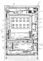
Hereinafter, embodiments of the present invention will be described with reference to the accompanying drawings. First, with reference to FIGS. 1 to 16, one embodiment when the present invention is applied to a pachinko gaming machine (hereinafter, simply referred to as “pachinko machine”) 10 as a first embodiment will be described. FIG. 1 is a front view of the pachinko machine 10 according to the first embodiment, FIG. 2 is a front view of the game board 13 of the pachinko machine 10, and FIG. 3 is a rear view of the pachinko machine 10.
なお、以下の説明では、図1に示す状態のパチンコ機10に対して、紙面手前側を前方(正面)側として、紙面奥側を後方(背面)側として説明する。また、図1に示す状態のパチンコ機10に対して、上側を上方(上)側として、下側を下方(下)側として、右側を右方(右)側として、左側を左方(左)側としてそれぞれ説明する。さらに、図中(例えば、図2参照)の矢印U−D,L−R,F−Bは、パチンコ機10の上下方向,左右方向,前後方向をそれぞれ示している。
In the following description, the pachinko machine 10 in the state shown in FIG. 1 will be described with the front side of the paper surface as the front (front) side and the back side of the paper surface as the rear (rear) side. Further, with respect to the pachinko machine 10 in the state shown in FIG. 1, the upper side is the upper (upper) side, the lower side is the lower (lower) side, the right side is the right (right) side, and the left side is the left side (left). ) Side will be explained respectively. Further, the arrows UD, LR, and FB in the drawing (see, for example, FIG. 2) indicate the vertical direction, the horizontal direction, and the front-rear direction of the pachinko machine 10.
図1に示すように、パチンコ機10は、略矩形状に組み合わせた木枠により外殻が形成される外枠11と、その外枠11と略同一の外形形状に形成され外枠11に対して開閉可能に支持された内枠12とを備えている。外枠11には、内枠12を支持するために正面視(図1参照)左側の上下2カ所に金属製のヒンジ18が取り付けられ、そのヒンジ18が設けられた側を開閉の軸として内枠12が正面手前側へ開閉可能に支持されている。
As shown in FIG. 1, the pachinko machine 10 has an outer frame 11 in which an outer shell is formed by a wooden frame combined in a substantially rectangular shape, and an outer frame 11 formed in substantially the same outer shape as the outer frame 11. It is provided with an inner frame 12 that is supported so as to be openable and closable. Metal hinges 18 are attached to the outer frame 11 at two upper and lower positions on the left side of the front view (see FIG. 1) in order to support the inner frame 12, and the side on which the hinge 18 is provided is used as an opening / closing axis. The frame 12 is supported so as to be openable and closable toward the front side of the front surface.
内枠12には、多数の釘や入賞口63,64等を有する遊技盤13(図2参照)が裏面側から着脱可能に装着される。この遊技盤13の正面を球(遊技球)が流下することにより弾球遊技が行われる。なお、内枠12には、球を遊技盤13の正面領域に発射する球発射ユニット112a(図4参照)やその球発射ユニット112aから発射された球を遊技盤13の正面領域まで誘導する発射レール(図示せず)等が取り付けられている。
A game board 13 (see FIG. 2) having a large number of nails, winning openings 63, 64, etc. is detachably attached to the inner frame 12 from the back surface side. A ball game is performed by a ball (game ball) flowing down in front of the game board 13. The inner frame 12 includes a ball launching unit 112a (see FIG. 4) that launches a ball into the front region of the game board 13 and a launch that guides a ball launched from the ball launching unit 112a to the front region of the game board 13. Rails (not shown) etc. are attached.
内枠12の正面側には、その正面上側を覆う正面枠14と、その下側を覆う下皿ユニット15とが設けられている。正面枠14及び下皿ユニット15を支持するために正面視(図1参照)左側の上下2カ所に金属製のヒンジ19が取り付けられ、そのヒンジ19が設けられた側を開閉の軸として正面枠14及び下皿ユニット15が正面手前側へ開閉可能に支持されている。なお、内枠12の施錠と正面枠14の施錠とは、シリンダ錠20の鍵穴21に専用の鍵を差し込んで所定の操作を行うことでそれぞれ解除される。
On the front side of the inner frame 12, a front frame 14 that covers the upper side of the front surface and a lower plate unit 15 that covers the lower side thereof are provided. In order to support the front frame 14 and the lower plate unit 15, metal hinges 19 are attached to the upper and lower two places on the left side of the front view (see FIG. 1), and the side on which the hinges 19 are provided is used as an opening / closing axis for the front frame. The 14 and the lower plate unit 15 are supported so as to be openable and closable toward the front side of the front surface. The lock of the inner frame 12 and the lock of the front frame 14 are released by inserting a dedicated key into the keyhole 21 of the cylinder lock 20 and performing a predetermined operation.
正面枠14は、装飾用の樹脂部品や電気部品等を組み付けたものであり、その略中央部には略楕円形状に開口形成された窓部14cが設けられている。正面枠14の裏面側には2枚の板ガラスを有するガラスユニット16が配設され、そのガラスユニット16を介して遊技盤13の正面がパチンコ機10の正面側に視認可能となっている。
The front frame 14 is formed by assembling decorative resin parts, electric parts, and the like, and a window portion 14c having a substantially elliptical opening is provided at a substantially central portion thereof. A glass unit 16 having two flat glass sheets is arranged on the back surface side of the front frame 14, and the front surface of the game board 13 can be visually recognized on the front side of the pachinko machine 10 through the glass unit 16.
正面枠14には、球を貯留する上皿17が正面側へ張り出して上面を開放した略箱状に形成されており、この上皿17に賞球や貸出球などが排出される。上皿17の底面は正面視(図1参照)右側に下降傾斜して形成され、その傾斜により上皿17に投入された球が球発射ユニット112a(図4参照)へと案内される。また、上皿17の上面には、枠ボタン22が設けられている。この枠ボタン22は、例えば、第3図柄表示装置81(図2参照)で表示される演出のステージを変更したり、スーパーリーチの演出内容を変更したりする場合などに、遊技者により操作される。
In the front frame 14, an upper plate 17 for storing balls is formed in a substantially box shape with the upper surface open so as to project toward the front side, and prize balls, rented balls, and the like are discharged to the upper plate 17. The bottom surface of the upper plate 17 is formed so as to be inclined downward to the right side when viewed from the front (see FIG. 1), and the ball thrown into the upper plate 17 is guided to the ball launching unit 112a (see FIG. 4) by the inclination. Further, a frame button 22 is provided on the upper surface of the upper plate 17. The frame button 22 is operated by the player, for example, when changing the stage of the effect displayed on the third symbol display device 81 (see FIG. 2) or changing the effect content of the super reach. To.
正面枠14には、その周囲(例えばコーナー部分)に各種ランプ等の発光手段が設けられている。これら発光手段は、大当たり時や所定のリーチ時等における遊技状態の変化に応じて、点灯又は点滅することにより発光態様が変更制御され、遊技中の演出効果を高める役割を果たす。窓部14cの周縁には、LED等の発光手段を内蔵した電飾部29〜33が設けられている。パチンコ機10においては、これら電飾部29〜33が大当たりランプ等の演出ランプとして機能し、大当たり時やリーチ演出時等には内蔵するLEDの点灯や点滅によって各電飾部29〜33が点灯または点滅して、大当たり中である旨、或いは大当たり一歩手前のリーチ中である旨が報知される。また、正面枠14の正面視(図1参照)左上部には、LED等の発光手段が内蔵され賞球の払い出し中とエラー発生時とを表示可能な表示ランプ34が設けられている。
The front frame 14 is provided with light emitting means such as various lamps around the front frame 14 (for example, a corner portion). These light emitting means change and control the light emitting mode by lighting or blinking according to a change in the gaming state at the time of a big hit or a predetermined reach, and play a role of enhancing the effect during the game. Illuminations 29 to 33 having a light emitting means such as an LED are provided on the peripheral edge of the window portion 14c. In the pachinko machine 10, these illumination units 29 to 33 function as effect lamps such as jackpot lamps, and each illumination unit 29 to 33 lights up by lighting or blinking the built-in LED at the time of jackpot or reach production. Or, it blinks to notify that the jackpot is in progress or that the reach is one step before the jackpot. Further, in the upper left portion of the front frame 14 when viewed from the front (see FIG. 1), a light emitting means such as an LED is built in, and a display lamp 34 capable of displaying when the prize ball is being paid out and when an error occurs is provided.
また、右側の電飾部32下側には、正面枠14の裏面側を視認できるように裏面側より透明樹脂を取り付けて小窓35が形成され、遊技盤13正面の貼着スペースK1(図2参照)に貼付される証紙等がパチンコ機10の正面から視認可能とされている。また、パチンコ機10においては、より煌びやかさを醸し出すために、電飾部29〜33の周りの領域にクロムメッキを施したABS樹脂製のメッキ部材36が取り付けられている。
Further, on the lower side of the illuminated portion 32 on the right side, a small window 35 is formed by attaching a transparent resin from the back side so that the back side of the front frame 14 can be visually recognized, and a sticking space K1 (FIG. The certificate stamp or the like attached to (see 2) can be visually recognized from the front of the pachinko machine 10. Further, in the pachinko machine 10, in order to bring out more glitter, a plating member 36 made of ABS resin having chrome plating is attached to a region around the illuminated portions 29 to 33.
窓部14cの下方には、貸球操作部40が配設されている。貸球操作部40には、度数表示部41と、球貸しボタン42と、返却ボタン43とが設けられている。パチンコ機10の側方に配置されるカードユニット(球貸しユニット)(図示せず)に紙幣やカード等を投入した状態で貸球操作部40が操作されると、その操作に応じて球の貸出が行われる。具体的には、度数表示部41はカード等の残額情報が表示される領域であり、内蔵されたLEDが点灯して残額情報として残額が数字で表示される。球貸しボタン42は、カード等(記録媒体)に記録された情報に基づいて貸出球を得るために操作されるものであり、カード等に残額が存在する限りにおいて貸出球が上皿17に供給される。返却ボタン43は、カードユニットに挿入されたカード等の返却を求める際に操作される。なお、カードユニットを介さずに球貸し装置等から上皿17に球が直接貸し出されるパチンコ機、いわゆる現金機では貸球操作部40が不要となるが、この場合には、貸球操作部40の設置部分に飾りシール等を付加して部品構成は共通のものとしても良い。カードユニットを用いたパチンコ機と現金機との共通化を図ることができる。
A ball lending operation unit 40 is arranged below the window unit 14c. The ball lending operation unit 40 is provided with a frequency display unit 41, a ball lending button 42, and a return button 43. When the ball lending operation unit 40 is operated with bills, cards, etc. inserted into the card unit (ball lending unit) (not shown) arranged on the side of the pachinko machine 10, the ball is operated according to the operation. Lending is done. Specifically, the frequency display unit 41 is an area in which balance information such as a card is displayed, and the built-in LED lights up and the balance is displayed as numerical value as balance information. The ball lending button 42 is operated to obtain a lending ball based on the information recorded on the card or the like (recording medium), and the lending ball is supplied to the upper plate 17 as long as the remaining amount is present on the card or the like. Will be done. The return button 43 is operated when requesting the return of the card or the like inserted in the card unit. A pachinko machine in which balls are lent directly to the upper plate 17 from a ball lending device or the like without going through a card unit, a so-called cash machine, does not require a ball lending operation unit 40. In this case, the ball lending operation unit 40 is not required. A decorative sticker or the like may be added to the installation portion of the above to make the component configuration common. It is possible to standardize pachinko machines and cash machines that use card units.
上皿17の下側に位置する下皿ユニット15には、その左側部に上皿17に貯留しきれなかった球を貯留するための下皿50が上面を開放した略箱状に形成されている。下皿50の右側には、球を遊技盤13の正面へ打ち込むために遊技者によって操作される操作ハンドル51が配設される。
In the lower plate unit 15 located on the lower side of the upper plate 17, a lower plate 50 for storing balls that could not be stored in the upper plate 17 is formed on the left side thereof in a substantially box shape with an open upper surface. There is. On the right side of the lower plate 50, an operation handle 51 operated by a player to drive the ball into the front of the game board 13 is arranged.
操作ハンドル51の内部には、球発射ユニット112aの駆動を許可するためのタッチセンサ51aと、押下操作している期間中には球の発射を停止する発射停止スイッチ51bと、操作ハンドル51の回動操作量(回動位置)を電気抵抗の変化により検出する可変抵抗器(図示せず)などが内蔵されている。操作ハンドル51が遊技者によって右回りに回動操作されると、タッチセンサ51aがオンされると共に可変抵抗器の抵抗値が回動操作量に対応して変化し、その可変抵抗器の抵抗値に対応した強さ(発射強度)で球が発射され、これにより遊技者の操作に対応した飛び量で遊技盤13の正面へ球が打ち込まれる。また、操作ハンドル51が遊技者により操作されていない状態においては、タッチセンサ51aおよび発射停止スイッチ51bがオフとなっている。
Inside the operation handle 51, there is a touch sensor 51a for permitting the driving of the ball launch unit 112a, a launch stop switch 51b for stopping the launch of the ball during the pressing operation period, and a rotation of the operation handle 51. It has a built-in variable resistor (not shown) that detects the amount of dynamic operation (rotation position) by the change in electrical resistance. When the operation handle 51 is rotated clockwise by the player, the touch sensor 51a is turned on and the resistance value of the variable resistor changes according to the amount of rotation operation, and the resistance value of the variable resistor is changed. The ball is launched with a strength (launching intensity) corresponding to the above, and the ball is driven into the front of the game board 13 with a flying amount corresponding to the operation of the player. Further, when the operation handle 51 is not operated by the player, the touch sensor 51a and the firing stop switch 51b are turned off.
下皿50の正面下方部には、下皿50に貯留された球を下方へ排出する際に操作するための球抜きレバー52が設けられている。この球抜きレバー52は、常時、右方向に付勢されており、その付勢に抗して左方向へスライドさせることにより、下皿50の底面に形成された底面口が開口して、その底面口から球が自然落下して排出される。この球抜きレバー52の操作は、通常、下皿50の下方に下皿50から排出された球を受け取る箱(一般に「千両箱」と称される)を置いた状態で行われる。下皿50の右方には、上述したように操作ハンドル51が配設され、下皿50の左方には灰皿(図示せず)が取り付けられている。
A ball pulling lever 52 for operating the ball stored in the lower plate 50 when the ball stored in the lower plate 50 is discharged downward is provided in the lower portion of the front surface of the lower plate 50. The ball pulling lever 52 is always urged to the right, and by sliding it to the left against the urging, the bottom opening formed on the bottom surface of the lower plate 50 is opened, and the bottom opening is opened. The ball naturally falls from the bottom opening and is discharged. The operation of the ball removing lever 52 is usually performed in a state where a box (generally referred to as a "thousand-car box") for receiving the balls discharged from the lower plate 50 is placed below the lower plate 50. An operation handle 51 is arranged on the right side of the lower plate 50 as described above, and an ashtray (not shown) is attached to the left side of the lower plate 50.
図2に示すように、遊技盤13は、正面視略正方形状に切削加工したベース板60に、球案内用の多数の釘(センターフレーム86の下方において図示し、遊技領域の上半部においては図示せず)や風車(図示せず)の他、レール61,62、一般入賞口63、第1入賞口64、第2入賞口140、可変入賞装置65、スルーゲート67、可変表示装置ユニット80等を組み付けて構成され、その周縁部が内枠12(図1参照)の裏面側に取り付けられる。
As shown in FIG. 2, the game board 13 has a large number of nails for ball guidance (shown below the center frame 86, in the upper half of the game area) on the base plate 60 cut into a substantially square shape in the front view. (Not shown) and windmill (not shown), rails 61, 62, general winning opening 63, first winning opening 64, second winning opening 140, variable winning device 65, through gate 67, variable display device unit. It is configured by assembling 80 and the like, and its peripheral edge is attached to the back surface side of the inner frame 12 (see FIG. 1).
ベース板60は、光透過性の樹脂材料から形成されており、その正面側からベース板60の背面側に配設された各種構造体を遊技者に視認させることが可能となっている。一般入賞口63、第1入賞口64、第2入賞口140及び可変入賞装置65は、ルータ加工によってベース板60に形成された貫通穴に配設され、遊技盤13の正面側からタッピングネジ等により固定されている。
The base plate 60 is made of a light-transmitting resin material, and various structures arranged on the back side of the base plate 60 can be visually recognized by the player from the front side thereof. The general winning opening 63, the first winning opening 64, the second winning opening 140, and the variable winning device 65 are arranged in a through hole formed in the base plate 60 by router processing, and a tapping screw or the like is provided from the front side of the game board 13. Is fixed by.
なお、ベース板60を木製の板部材から形成しても良い。この場合、センターフレーム86の外側において、その正面側からベース板60の背面側に配設された各種構造体を遊技者に視認不能に遮蔽することが可能となる。
The base plate 60 may be formed from a wooden plate member. In this case, on the outside of the center frame 86, various structures arranged on the back side of the base plate 60 from the front side thereof can be shielded invisible to the player.
遊技盤13の正面中央部分は、正面枠14の窓部14c(図1参照)を通じて内枠12の正面側から視認することができる。以下に、主に図2を参照して、遊技盤13の構成について説明する。
The front central portion of the game board 13 can be visually recognized from the front side of the inner frame 12 through the window portion 14c (see FIG. 1) of the front frame 14. Hereinafter, the configuration of the game board 13 will be described mainly with reference to FIG. 2.
遊技盤13の正面には、帯状の金属板を略円弧状に屈曲加工して形成した外レール62が植立され、その外レール62の内側位置には外レール62と同様に帯状の金属板で形成した円弧状の内レール61が植立される。この内レール61と外レール62とにより遊技盤13の正面外周が囲まれ、遊技盤13とガラスユニット16(図1参照)とにより前後が囲まれることにより、遊技盤13の正面には、球の挙動により遊技が行われる遊技領域が形成される。遊技領域は、遊技盤13の正面であって2本のレール61,62とレール間を繋ぐ樹脂製の外縁部材73とにより区画して形成される領域(入賞口等が配設され、発射された球が流下する領域)である。
An outer rail 62 formed by bending a strip-shaped metal plate into a substantially arc shape is planted on the front surface of the game board 13, and a strip-shaped metal plate is placed inside the outer rail 62 in the same manner as the outer rail 62. The arc-shaped inner rail 61 formed in 1 is planted. The inner rail 61 and the outer rail 62 surround the front outer circumference of the game board 13, and the game board 13 and the glass unit 16 (see FIG. 1) surround the front and back of the game board 13. A game area in which the game is played is formed by the behavior of. The game area is the area in front of the game board 13 that is partitioned by the two rails 61 and 62 and the resin outer edge member 73 that connects the rails (a winning opening or the like is arranged and fired). This is the area where the rails flow down.
2本のレール61,62は、球発射ユニット112a(図4参照)から発射された球を遊技盤13上部へ案内するために設けられたものである。内レール61の先端部分(図2の左上部)には戻り球防止部材68が取り付けられ、一旦、遊技盤13の上部へ案内された球が再度球案内通路内に戻ってしまうといった事態が防止される。外レール62の先端部(図2の右上部)には、球の最大飛翔部分に対応する位置に返しゴム69が取り付けられ、所定以上の勢いで発射された球は、返しゴム69に当たって、勢いが減衰されつつ中央部側へ跳ね返される。
The two rails 61 and 62 are provided to guide the ball launched from the ball launching unit 112a (see FIG. 4) to the upper part of the game board 13. A return ball prevention member 68 is attached to the tip of the inner rail 61 (upper left portion in FIG. 2) to prevent the ball once guided to the upper part of the game board 13 from returning to the ball guide passage. Will be done. A return rubber 69 is attached to the tip of the outer rail 62 (upper right part in FIG. 2) at a position corresponding to the maximum flight portion of the ball, and the ball launched with a predetermined momentum hits the return rubber 69 and has momentum. Is dampened and bounced back toward the center.
遊技領域の正面視左側下部(図2の左側下部)には、発光手段である複数のLED及び7セグメント表示器を備える第1図柄表示装置37A,37Bが配設されている。第1図柄表示装置37A,37Bは、主制御装置110(図4参照)で行われる各制御に応じた表示がなされるものであり、主にパチンコ機10の遊技状態の表示が行われる。本実施形態では、第1図柄表示装置37A,37Bは、球が、第1入賞口64へ入賞したか、第2入賞口140へ入賞したかに応じて使い分けられるように構成されている。具体的には、球が、第1入賞口64へ入賞した場合には、第1図柄表示装置37Aが作動し、一方で、球が、第2入賞口140へ入賞した場合には、第1図柄表示装置37Bが作動するように構成されている。
In the lower left side of the front view (lower left side of FIG. 2) of the game area, first symbol display devices 37A and 37B including a plurality of LEDs as light emitting means and a 7-segment display are arranged. The first symbol display devices 37A and 37B display according to each control performed by the main control device 110 (see FIG. 4), and mainly display the gaming state of the pachinko machine 10. In the present embodiment, the first symbol display devices 37A and 37B are configured to be used properly depending on whether the ball has won the first winning opening 64 or the second winning opening 140. Specifically, when the ball wins the first winning opening 64, the first symbol display device 37A operates, while when the ball wins the second winning opening 140, the first The symbol display device 37B is configured to operate.
また、第1図柄表示装置37A,37Bは、LEDにより、パチンコ機10が確変中か時短中か通常中であるかを点灯状態により示したり、変動中であるか否かを点灯状態により示したり、停止図柄が確変大当たりに対応した図柄か普通大当たりに対応した図柄か外れ図柄であるかを点灯状態により示したり、保留球数を点灯状態により示すと共に、7セグメント表示装置により、大当たり中のラウンド数やエラー表示を行う。なお、複数のLEDは、それぞれのLEDの発光色(例えば、赤、緑、青)が異なるよう構成され、その発光色の組み合わせにより、少ないLEDでパチンコ機10の各種遊技状態を示唆することができる。
Further, the first symbol display devices 37A and 37B use LEDs to indicate whether the pachinko machine 10 is in the probabilistic change, the time reduction, or the normal state by the lighting state, or indicate whether the pachinko machine 10 is in the changing state or not by the lighting state. , Whether the stop symbol is a symbol corresponding to the probability variation jackpot, a symbol corresponding to the normal jackpot, or a missed symbol is indicated by the lighting state, the number of reserved balls is indicated by the lighting state, and the round during the jackpot is indicated by the 7-segment display device. Display the number and error. It should be noted that the plurality of LEDs are configured so that the emission colors (for example, red, green, blue) of the respective LEDs are different, and the combination of the emission colors can suggest various gaming states of the pachinko machine 10 with a small number of LEDs. it can.
尚、本パチンコ機10では、第1入賞口64及び第2入賞口140へ入賞があったことを契機として抽選が行われる。パチンコ機10は、その抽選において、大当たりか否かの当否判定(大当たり抽選)を行うと共に、大当たりと判定した場合はその大当たり種別の判定も行う。ここで判定される大当たり種別としては、15R確変大当たり、4R確変大当たり、4R通常大当たりが用意されている。第1図柄表示装置37A,37Bには、変動終了後の停止図柄として抽選の結果が大当たりであるか否かが示されるだけでなく、大当たりである場合はその大当たり種別に応じた図柄が示される。
In the pachinko machine 10, a lottery is performed when the first winning opening 64 and the second winning opening 140 have won a prize. In the lottery, the pachinko machine 10 determines whether or not it is a big hit (big hit lottery), and if it is determined to be a big hit, it also determines the type of the big hit. As the jackpot type determined here, a 15R probability variation jackpot, a 4R probability variation jackpot, and a 4R normal jackpot are prepared. The first symbol display devices 37A and 37B not only indicate whether or not the result of the lottery is a big hit as a stop symbol after the end of the fluctuation, and if it is a big hit, a symbol corresponding to the jackpot type is shown. ..
ここで、「15R確変大当たり」とは、最大ラウンド数が15ラウンドの大当たりの後に高確率状態へ移行する確変大当たりのことであり、「4R確変大当たり」とは、最大ラウンド数が4ラウンドの大当たりの後に高確率状態へ移行する確変大当たりのことである。また、「4R通常大当たり」は、最大ラウンド数が4ラウンドの大当たりの後に、低確率状態へ移行すると共に、所定の変動回数の間(例えば、100変動回数)は時短状態となる大当たりのことである。
Here, the "15R probability variation jackpot" is a probability variation jackpot in which the maximum number of rounds shifts to a high probability state after the jackpot of 15 rounds, and the "4R probability variation jackpot" is a jackpot with a maximum number of rounds of 4 rounds. It is a probabilistic jackpot that shifts to a high probability state after. Further, "4R normal jackpot" is a jackpot in which the maximum number of rounds is 4 rounds, and then the probability shifts to a low probability state, and the time is shortened during a predetermined number of fluctuations (for example, 100 fluctuations). is there.
また、「高確率状態」とは、大当たり終了後に付加価値としてその後の大当たり確率がアップした状態、いわゆる確率変動中(確変中)の時をいい、換言すれば、特別遊技状態へ移行し易い遊技の状態のことである。本実施形態における高確率状態(確変中)は、所定の変動回数の間(本実施形態では、100変動回数)、大当たり確率がアップし、後述する第2図柄の当たり確率がアップして第2入賞口140へ球が入賞し易い遊技の状態を含む。「低確率状態」とは、確変中でない時をいい、大当たり確率が通常の状態、即ち、確変の時より大当たり確率が低い状態をいう。また、「低確率状態」のうちの時短状態(時短中)とは、大当たり確率が通常の状態であると共に、大当たり確率がそのままで第2図柄の当たり確率のみがアップして第2入賞口140へ球が入賞し易い遊技の状態のことをいう。一方、パチンコ機10が通常中とは、確変中でも時短中でもない遊技の状態(大当たり確率も第2図柄の当たり確率もアップしていない状態)である。
In addition, the "high probability state" refers to a state in which the subsequent jackpot probability increases as an added value after the end of the jackpot, that is, during so-called probability fluctuation (probability change), in other words, a game in which it is easy to shift to a special gaming state. It is the state of. In the high probability state (during probabilistic change) in the present embodiment, the jackpot probability increases during a predetermined number of fluctuations (100 fluctuations in the present embodiment), and the hit probability of the second symbol described later increases and the second Includes a game state in which a ball can easily win a prize in the winning opening 140. The "low probability state" refers to a state in which the probability change is not in progress, and a state in which the jackpot probability is normal, that is, a state in which the jackpot probability is lower than that in the probability change state. In the "low probability state", the time saving state (during the time saving) is a state in which the jackpot probability is a normal state, and the jackpot probability remains the same and only the hit probability of the second symbol is increased to increase the second winning opening 140. It refers to the state of the game in which the ball is easy to win. On the other hand, when the pachinko machine 10 is in the normal state, it is a state of the game in which neither the probability change nor the time reduction is performed (the jackpot probability and the hit probability of the second symbol are not increased).
本実施形態では、後述する振分装置300の確変検出センサSE11の貫通孔を、大当たり遊技の1ラウンド目に遊技球が通過したと判定された時に、その大当たり遊技終了後の遊技状態が100変動回数の間、高確率状態となる。なお、確変検出センサSE11の貫通孔に遊技球が通過したと判定されなかったら大当たり遊技終了後の遊技状態が100変動回数の間、時短状態となる。
In the present embodiment, when it is determined that the game ball has passed through the through hole of the probability variation detection sensor SE11 of the distribution device 300, which will be described later, in the first round of the jackpot game, the gaming state after the jackpot game ends changes by 100. It becomes a high probability state for the number of times. If it is not determined that the game ball has passed through the through hole of the probability variation detection sensor SE11, the game state after the jackpot game ends will be in a time-saving state for 100 fluctuations.
確変中や時短中は、第2図柄の当たり確率がアップするだけではなく、第2入賞口140に付随する電動役物140a(電動役物)が開放される時間も変更され、通常中と比して長い時間が設定される。電動役物140aが開放された状態(開放状態)にある場合は、その電動役物140aが閉鎖された状態(閉鎖状態)にある場合と比して、第2入賞口140へ球が入賞しやすい状態となる。よって、確変中や時短中は、第2入賞口140へ球が入賞し易い状態となり、大当たり抽選が行われる回数を増やすことができる。
During the probability change and the time reduction, not only the hit probability of the second symbol increases, but also the time when the electric accessory 140a (electric accessory) attached to the second winning opening 140 is opened is changed, which is compared with the normal time. And a long time is set. When the electric accessory 140a is in the open state (open state), the ball wins the second winning opening 140 as compared with the case where the electric accessory 140a is in the closed state (closed state). It will be easy. Therefore, during the probability change or the time reduction, it becomes easy for the ball to win the second winning opening 140, and the number of times the big hit lottery is performed can be increased.
なお、確変中や時短中において、第2入賞口140に付随する電動役物140aの開放時間を変更するのではなく、または、その開放時間を変更することに加えて、1回の当たりで電動役物140aが開放する回数を通常中よりも増やす変更を行うものとしてもよい。また、確変中や時短中において、第2図柄の当たり確率は変更せず、第2入賞口140に付随する電動役物140aが開放される時間および1回の当たりで電動役物140aが開放する回数の少なくとも一方を変更するものとしてもよい。また、確変中や時短中において、第2入賞口140に付随する電動役物140aが開放される時間や、1回の当たりで電動役物140aを開放する回数はせず、第2図柄の当たり確率だけを、通常中と比してアップするよう変更するものであってもよい。
In addition, during the probability change or the time reduction, the opening time of the electric accessory 140a attached to the second winning opening 140 is not changed, or in addition to changing the opening time, electric power is applied at one time. The change may be made so that the number of times that the accessory 140a is opened is increased from the normal time. Further, during the probability change or the time reduction, the hit probability of the second symbol is not changed, and the electric accessory 140a is opened at the time when the electric accessory 140a attached to the second winning opening 140 is opened and at one time. At least one of the times may be changed. In addition, during the probability change or the time reduction, the time when the electric accessory 140a attached to the second winning opening 140 is opened and the number of times when the electric accessory 140a is opened per hit is not performed, and the second symbol is hit. Only the probability may be changed so as to be higher than the normal one.
遊技領域には、球が入賞することにより5個から15個の球が賞球として払い出される複数の一般入賞口63が配設されている。また、遊技領域の中央部分には、可変表示装置ユニット80が配設されている。可変表示装置ユニット80には、第1入賞口64及び第2入賞口140への入賞(始動入賞)をトリガとして、第1図柄表示装置37A,37Bにおける変動表示と同期させながら、第3図柄の変動表示を行う液晶ディスプレイ(以下単に「表示装置」と略す)で構成された第3図柄表示装置81と、スルーゲート67の球の通過をトリガとして第2図柄を変動表示するLEDで構成される第2図柄表示装置(図示せず)とが設けられている。また、正面視において可変表示装置ユニット80の第3図柄表示装置81の外周を囲むようにして、センターフレーム86が配設されている。
In the game area, a plurality of general winning openings 63 are arranged in which 5 to 15 balls are paid out as prize balls when the balls are won. Further, a variable display device unit 80 is arranged in the central portion of the game area. The variable display device unit 80 is triggered by winning a prize (starting prize) in the first winning opening 64 and the second winning opening 140, and is synchronized with the variable display in the first symbol display devices 37A and 37B to display the third symbol. It is composed of a third symbol display device 81 composed of a liquid crystal display (hereinafter simply abbreviated as "display device") that performs variable display, and an LED that variablely displays the second symbol triggered by the passage of a sphere of a through gate 67. A second symbol display device (not shown) is provided. Further, the center frame 86 is arranged so as to surround the outer periphery of the third symbol display device 81 of the variable display device unit 80 in front view.
なお、本実施形態では、第3図柄表示装置81は遊技盤13の背面に固定される背面ケースに締結固定され、センターフレーム86はベース板60の窓部(中央開口60b)を縁取るように配設されている。即ち、正面視では第3図柄表示装置81の外周を囲むようにセンターフレーム86が配設されているように見えるが、実際は、第3図柄表示装置81とセンターフレーム86とは前後に離れて配置されている。
In the present embodiment, the third symbol display device 81 is fastened and fixed to the back case fixed to the back surface of the game board 13, and the center frame 86 borders the window portion (center opening 60b) of the base plate 60. It is arranged. That is, when viewed from the front, it seems that the center frame 86 is arranged so as to surround the outer periphery of the third symbol display device 81, but in reality, the third symbol display device 81 and the center frame 86 are arranged apart from each other in the front-rear direction. Has been done.
第3図柄表示装置81は、例えば9インチサイズの大型の液晶ディスプレイで構成されるものであり、表示制御装置114(図4参照)によって表示内容が制御されることにより、例えば上、中及び下の3つの図柄列が表示される。各図柄列は複数の図柄(第3図柄)によって構成され、これらの第3図柄が図柄列毎に横スクロールして第3図柄表示装置81の表示画面上にて第3図柄が可変表示されるようになっている。本実施形態の第3図柄表示装置81は、主制御装置110(図4参照)の制御に伴った遊技状態の表示が第1図柄表示装置37A,37Bで行われるのに対して、その第1図柄表示装置37A,37Bの表示に応じた装飾的な表示を行うものである。なお、表示装置に代えて、例えばリール等を用いて第3図柄表示装置81を構成するようにしても良い。
The third symbol display device 81 is composed of, for example, a large liquid crystal display having a size of 9 inches, and by controlling the display contents by the display control device 114 (see FIG. 4), for example, upper, middle, and lower. Three symbol rows of are displayed. Each symbol row is composed of a plurality of symbols (third symbol), and these third symbols are horizontally scrolled for each symbol row, and the third symbol is variably displayed on the display screen of the third symbol display device 81. It has become like. In the third symbol display device 81 of the present embodiment, the game state displayed by the control of the main control device 110 (see FIG. 4) is displayed by the first symbol display devices 37A and 37B, whereas the first of the third symbol display devices 81 is A decorative display is performed according to the display of the symbol display devices 37A and 37B. In addition, instead of the display device, for example, a reel or the like may be used to configure the third symbol display device 81.
第2図柄表示装置は、球がスルーゲート67を通過する毎に表示図柄(第2図柄(図示せず))としての「○」の図柄と「×」の図柄とを所定時間交互に点灯させる変動表示を行うものである。パチンコ機10では、球がスルーゲート67を通過したことが検出されると、当たり抽選が行われる。その当たり抽選の結果、当たりであれば、第2図柄表示装置において、第2図柄の変動表示後に「○」の図柄が停止表示される。また、当たり抽選の結果、外れであれば、第2図柄表示装置において、第3図柄の変動表示後に「×」の図柄が停止表示される。
The second symbol display device alternately lights the “○” symbol and the “×” symbol as the display symbol (second symbol (not shown)) each time the sphere passes through the through gate 67 for a predetermined time. It is a variable display. When the pachinko machine 10 detects that the ball has passed through the through gate 67, a winning lottery is performed. As a result of the winning lottery, if it is a winning, the symbol "○" is stopped and displayed on the second symbol display device after the variation display of the second symbol. Further, if the result of the winning lottery is a failure, the symbol "x" is stopped and displayed on the second symbol display device after the variation display of the third symbol.
パチンコ機10は、第2図柄表示装置における変動表示が所定図柄(本実施形態においては「○」の図柄)で停止した場合に、第2入賞口140に付随された電動役物140aが所定時間だけ作動状態となる(開放される)よう構成されている。
In the pachinko machine 10, when the variation display in the second symbol display device is stopped at a predetermined symbol (in the present embodiment, the symbol “○”), the electric accessory 140a attached to the second winning opening 140 is used for a predetermined time. It is configured to be activated (opened) only.
第2図柄の変動表示にかかる時間は、遊技状態が通常中の場合よりも、確変中または時短中の方が短くなるように設定される。これにより、確変中および時短中は、第2図柄の変動表示が短い時間で行われるので、当たり抽選を通常中よりも多く行うことができる。よって、当たり抽選において当たりとなる機会が増えるので、第2入賞口140の電動役物140aが開放状態となる機会を遊技者に多く与えることができる。よって、確変中および時短中は、第2入賞口140へ球が入賞しやすい状態とすることができる。
The time required for the variation display of the second symbol is set to be shorter during the probability change or the time reduction than when the game state is normal. As a result, during the probability change and the time reduction, the variation display of the second symbol is performed in a short time, so that the winning lottery can be performed more than during the normal time. Therefore, since the chances of winning in the winning lottery increase, it is possible to give the player many opportunities to open the electric accessory 140a of the second winning opening 140. Therefore, it is possible to make it easy for the ball to win the second winning opening 140 during the probability change and the time saving.
なお、確変中または時短中において、当たり確率を高める、1回に当たりに対する電動役物140aの開放時間や開放回数を増やすなど、その他の方法によっても、確変中または時短中に第2入賞口140へ球が入賞しやすい状態としている場合は、第2図柄の変動表示にかかる時間を遊技状態にかかわらず一定としてもよい。一方、第2図柄の変動表示にかかる時間を、確変中または時短中において通常中よりも短く設定する場合は、当たり確率を遊技状態にかかわらず一定にしてもよいし、また、1回の当たりに対する電動役物140aの開放時間や開放回数を遊技状態にかかわらず一定にしてもよい。
In addition, during the probability change or the time reduction, the second winning opening 140 can be reached during the probability change or the time reduction by other methods such as increasing the opening time and the number of times of opening the electric accessory 140a per hit. When the ball is in a state where it is easy to win a prize, the time required for the variable display of the second symbol may be constant regardless of the gaming state. On the other hand, when the time required for the variation display of the second symbol is set to be shorter than the normal time during the probability change or the time reduction, the hit probability may be constant regardless of the gaming state, or one hit. The opening time and the number of times of opening the electric accessory 140a may be constant regardless of the gaming state.
スルーゲート67は、可変表示装置ユニット80の左右の領域において遊技盤13に組み付けられ、遊技盤13に発射された球の一部が通過可能に構成されている。スルーゲート67を球が通過すると、第2図柄の当たり抽選が行われる。当たり抽選の後、第2図柄表示装置にて変動表示を行い、当たり抽選の結果が当たりであれば、変動表示の停止図柄として「○」の図柄を表示し、当たり抽選の結果が外れであれば、変動表示の停止図柄として「×」の図柄を表示する。
The through gate 67 is assembled to the game board 13 in the left and right regions of the variable display device unit 80, and is configured so that a part of the balls launched on the game board 13 can pass through. When the ball passes through the through gate 67, a winning lottery for the second symbol is performed. After the winning lottery, variable display is performed on the second symbol display device, and if the winning lottery result is a winning symbol, a symbol "○" is displayed as a stop symbol of the variable display, and if the winning lottery result is incorrect. For example, a symbol of "x" is displayed as a stop symbol of the variable display.
球のスルーゲート67の通過回数は、合計で最大4回まで保留され、その保留球数が上述した第1図柄表示装置37A,37Bにより表示されると共に第2図柄保留ランプ(図示せず)においても点灯表示される。第2図柄保留ランプは、最大保留数分の4つ設けられ、第3図柄表示装置81の下方に左右対称に配設されている。
The number of times the ball has passed through the through gate 67 is held up to a total of four times, and the number of held balls is displayed by the above-mentioned first symbol display devices 37A and 37B and on the second symbol holding lamp (not shown). Is also lit and displayed. Four second symbol holding lamps are provided for the maximum number of holding lamps, and are symmetrically arranged below the third symbol display device 81.
なお、第2図柄の変動表示は、本実施形態のように、第2図柄表示装置において複数のランプの点灯と非点灯を切り換えることにより行うものの他、第1図柄表示装置37A,37B及び第3図柄表示装置81の一部を使用して行うようにしても良い。同様に、第2図柄保留ランプの点灯を第3図柄表示装置81の一部で行うようにしても良い。また、スルーゲート67の球の通過に対する最大保留球数は4回に限定されるものでなく、3回以下、又は、5回以上の回数(例えば、8回)に設定しても良い。また、スルーゲート67の組み付け数は2つに限定されるものではなく、例えば1つであっても良い。また、スルーゲート67の組み付け位置は可変表示装置ユニット80の左右に限定されるものではなく、例えば、可変表示装置ユニット80の下方でも良い。また、第1図柄表示装置37A,37Bにより保留球数が示されるので、第2図柄保留ランプにより点灯表示を行わないものとしてもよい。
The variation display of the second symbol is performed by switching the lighting and non-lighting of a plurality of lamps in the second symbol display device as in the present embodiment, as well as the first symbol display devices 37A, 37B and the third. It may be performed by using a part of the symbol display device 81. Similarly, the second symbol holding lamp may be turned on by a part of the third symbol display device 81. Further, the maximum number of reserved balls for the passage of the balls of the through gate 67 is not limited to 4, but may be set to 3 times or less, or 5 times or more (for example, 8 times). Further, the number of through gates 67 assembled is not limited to two, and may be one, for example. Further, the assembly position of the through gate 67 is not limited to the left and right sides of the variable display device unit 80, and may be, for example, below the variable display device unit 80. Further, since the number of reserved balls is indicated by the first symbol display devices 37A and 37B, the lighting display may not be performed by the second symbol holding lamp.
可変表示装置ユニット80の下方には、球が入賞し得る第1入賞口64が配設されている。この第1入賞口64へ球が入賞すると遊技盤13の裏面側に設けられる第1入賞口スイッチ(図示せず)がオンとなり、その第1入賞口スイッチのオンに起因して主制御装置110(図4参照)で大当たりの抽選がなされ、その抽選結果に応じた表示が第1図柄表示装置37Aで示される。
Below the variable display device unit 80, a first winning opening 64 in which a ball can win a prize is arranged. When the ball wins the first winning opening 64, the first winning opening switch (not shown) provided on the back surface side of the game board 13 is turned on, and the main control device 110 is caused by the turning on of the first winning opening switch. A big hit lottery is made in (see FIG. 4), and the display according to the lottery result is shown by the first symbol display device 37A.
一方、第1入賞口64の正面視下方には、球が入賞し得る第2入賞口140が配設されている。この第2入賞口140へ球が入賞すると遊技盤13の裏面側に設けられる第2入賞口スイッチ(図示せず)がオンとなり、その第2入賞口スイッチのオンに起因して主制御装置110(図4参照)で大当たりの抽選がなされ、その抽選結果に応じた表示が第1図柄表示装置37Bで示される。
On the other hand, below the front view of the first winning opening 64, a second winning opening 140 in which the ball can win is arranged. When the ball wins the second winning opening 140, the second winning opening switch (not shown) provided on the back side of the game board 13 is turned on, and the main control device 110 is turned on due to the turning on of the second winning opening switch. A big hit lottery is made in (see FIG. 4), and the display according to the lottery result is shown on the first symbol display device 37B.
また、第1入賞口64および第2入賞口140は、それぞれ、球が入賞すると5個の球が賞球として払い出される入賞口の1つにもなっている。なお、本実施形態においては、第1入賞口64へ球が入賞した場合に払い出される賞球数と第2入賞口140へ球が入賞した場合に払い出される賞球数とを同じに構成したが、第1入賞口64へ球が入賞した場合に払い出される賞球数と第2入賞口140へ球が入賞した場合に払い出される賞球数とを異なる数、例えば、第1入賞口64へ球が入賞した場合に払い出される賞球数を3個とし、第2入賞口140へ球が入賞した場合に払い出される賞球数を5個として構成してもよい。
In addition, the first winning opening 64 and the second winning opening 140 are also one of the winning openings in which five balls are paid out as prize balls when the balls are won. In the present embodiment, the number of prize balls paid out when a ball wins in the first winning opening 64 and the number of winning balls paid out when a ball wins in the second winning opening 140 are configured to be the same. , The number of prize balls paid out when a ball wins in the first winning opening 64 and the number of prize balls paid out when a ball wins in the second winning opening 140, for example, a ball to the first winning opening 64 The number of prize balls to be paid out when a prize is won may be three, and the number of prize balls to be paid out when a ball is won to the second winning opening 140 may be configured to be five.
第2入賞口140には電動役物140aが付随されている。この電動役物140aは開閉可能に構成されており、通常は電動役物140aが閉鎖状態(縮小状態)となって、球が第2入賞口140へ入賞しにくい状態となっている。一方、スルーゲート67への球の通過を契機として行われる第2図柄の変動表示の結果、「○」の図柄が第2図柄表示装置に表示された場合、電動役物140aが開放状態(拡大状態)となり、球が第2入賞口140へ入賞しやすい状態となる。
An electric accessory 140a is attached to the second winning opening 140. The electric accessory 140a is configured to be openable and closable, and normally the electric accessory 140a is in a closed state (reduced state), making it difficult for the ball to win a prize in the second winning opening 140. On the other hand, when the symbol "○" is displayed on the second symbol display device as a result of the variation display of the second symbol performed when the ball passes through the through gate 67, the electric accessory 140a is in the open state (enlarged). State), and the ball is in a state where it is easy to win a prize in the second winning opening 140.
上述した通り、確変中および時短中は、通常中と比して第2図柄の当たり確率が高く、また、第2図柄の変動表示にかかる時間も短いので、第2図柄の変動表示において「○」の図柄が表示され易くなって、電動役物140aが開放状態(拡大状態)となる回数が増える。更に、確変中および時短中は、電動役物140aが開放される時間も、通常中より長くなる。よって、確変中および時短中は、通常時と比して、第2入賞口140へ球が入賞しやすい状態を作ることができる。
As described above, during the probability change and the time reduction, the probability of hitting the second symbol is higher than during the normal time, and the time required for the variation display of the second symbol is short. The symbol "" is easily displayed, and the number of times that the electric accessory 140a is in the open state (enlarged state) increases. Further, during the probability change and the time reduction, the time for opening the electric accessory 140a is also longer than during the normal operation. Therefore, during the probability change and the time reduction, it is possible to create a state in which the ball is more likely to win the second winning opening 140 as compared with the normal time.
ここで、第1入賞口64に球が入賞した場合と第2入賞口140へ球が入賞した場合とで、大当たりとなる確率は、低確率状態であっても高確率状態でも同一である。しかしながら、大当たりとなった場合に選定される大当たりの種別として15R確変大当たりとなる確率は、第2入賞口140へ球が入賞した場合のほうが第1入賞口64へ球が入賞した場合よりも高く設定されている。一方、第1入賞口64は、第2入賞口140にあるような電動役物は有しておらず、球が常時入賞可能な状態となっている。
Here, the probability of winning a jackpot is the same in both the low probability state and the high probability state when the ball wins in the first winning opening 64 and when the ball wins in the second winning opening 140. However, the probability of becoming a 15R probability variation jackpot as the type of jackpot selected in the case of a jackpot is higher when the ball wins the second winning opening 140 than when the ball wins the first winning opening 64. It is set. On the other hand, the first winning opening 64 does not have an electric accessory as in the second winning opening 140, and the ball is in a state where it can always win a prize.
よって、通常中においては、第2入賞口140に付随する電動役物が閉鎖状態にある場合が多く、第2入賞口140に入賞しづらいので、電動役物のない第1入賞口64へ向けて、可変表示装置ユニット80の左方を球が通過するように球を発射し(所謂「左打ち」)、第1入賞口64への入賞によって大当たり抽選の機会を多く得て、大当たりとなることを狙った方が、遊技者にとって有利となる。
Therefore, in normal times, the electric accessory attached to the second winning opening 140 is often in a closed state, and it is difficult to win the second winning opening 140. Then, the ball is fired so that the ball passes to the left side of the variable display device unit 80 (so-called "left-handed"), and by winning the first winning opening 64, many chances of a big hit lottery are obtained and the big hit is obtained. It is advantageous for the player to aim at that.
一方、確変中や時短中は、スルーゲート67に球を通過させることで、第2入賞口140に付随する電動役物140aが開放状態となりやすく、第2入賞口140に入賞しやすい状態であるので、第2入賞口140へ向けて、可変表示装置80の右方を球が通過するように球を発射し(所謂「右打ち」)、スルーゲート67を通過させて電動役物を開放状態にすると共に、第2入賞口140への入賞によって15R確変大当たりとなることを狙った方が、遊技者にとって有利となる。
On the other hand, during the probability change or the time reduction, by passing the ball through the through gate 67, the electric accessory 140a attached to the second winning opening 140 is likely to be opened, and the second winning opening 140 is likely to be won. Therefore, the ball is launched toward the second winning opening 140 so that the ball passes to the right of the variable display device 80 (so-called "right-handed"), and the electric accessory is opened by passing through the through gate 67. At the same time, it is advantageous for the player to aim for a 15R probability variation jackpot by winning the second winning opening 140.
なお、本実施形態におけるパチンコ機10は、遊技盤13の構成が左右対称とされるため、「右打ち」で第1入賞口64を狙うことも、「左打ち」で第2入賞口140を狙うこともできる。そのため、本実施形態のパチンコ機10は、パチンコ機10の遊技状態(確変中であるか、時短中であるか、通常中であるか)に応じて、遊技者に対し、球の発射の仕方を「左打ち」と「右打ち」とに変えさせることを不要にできる。よって、球の打ち方を変化させる煩わしさを解消することができる。
Since the pachinko machine 10 in the present embodiment has a symmetrical configuration of the game board 13, it is possible to aim at the first winning opening 64 by "right-handed" or to aim at the second winning opening 140 by "left-handing". You can also aim. Therefore, the pachinko machine 10 of the present embodiment is a method of firing a ball to the player according to the gaming state of the pachinko machine 10 (whether it is in the probabilistic change, in the time saving, or in the normal state). Can be eliminated from changing to "left-handed" and "right-handed". Therefore, it is possible to eliminate the hassle of changing the way the ball is hit.
第1入賞口64の下方には可変入賞装置65(図2参照)が配設されており、その略中央部分に特定入賞口65aが設けられている。パチンコ機10においては、第1入賞口64又は第2入賞口140への入賞に起因して行われた大当たり抽選が大当たりとなると、所定時間(変動時間)が経過した後に、大当たりの停止図柄となるよう第1図柄表示装置37A又は第1図柄表示装置37Bを点灯させると共に、その大当たりに対応した停止図柄を第3図柄表示装置81に表示させて、大当たりの発生が示される。その後、球が入賞し易い特別遊技状態(大当たり)に遊技状態が遷移する。この特別遊技状態として、通常時には閉鎖されている特定入賞口65aが、所定時間(例えば、30秒経過するまで、或いは、球が10個入賞するまで)開放される。
A variable winning device 65 (see FIG. 2) is arranged below the first winning opening 64, and a specific winning opening 65a is provided in a substantially central portion thereof. In the pachinko machine 10, when the jackpot lottery performed due to winning the first winning opening 64 or the second winning opening 140 becomes a jackpot, after a predetermined time (variable time) has elapsed, the jackpot stop symbol is displayed. The first symbol display device 37A or the first symbol display device 37B is turned on so that the stop symbol corresponding to the jackpot is displayed on the third symbol display device 81 to indicate the occurrence of the jackpot. After that, the gaming state transitions to a special gaming state (big hit) where the ball is easy to win. As this special game state, the specific winning opening 65a, which is normally closed, is opened for a predetermined time (for example, until 30 seconds have passed or until 10 balls are won).
この特定入賞口65aは、所定時間が経過すると閉鎖され、その閉鎖後、再度、その特定入賞口65aが所定時間開放される。この特定入賞口65aの開閉動作は、最高で例えば15回(15ラウンド)繰り返し可能にされている。この開閉動作が行われている状態が、遊技者にとって有利な特別遊技状態の一形態であり、遊技者には、遊技上の価値(遊技価値)の付与として通常時より多量の賞球の払い出しが行われる。
The specific winning opening 65a is closed after a lapse of a predetermined time, and after the closing, the specific winning opening 65a is opened again for a predetermined time. The opening / closing operation of the specific winning opening 65a can be repeated up to 15 times (15 rounds), for example. The state in which this opening / closing operation is performed is a form of a special gaming state that is advantageous for the player, and the player is given a larger amount of prize balls than usual as a game value (game value). Is done.
なお、上記した形態に特別遊技状態は限定されるものではない。特定入賞口65aとは別に開閉される大開放口を遊技領域に設け、第1図柄表示装置37A,37Bにおいて大当たりに対応したLEDが点灯した場合に、特定入賞口65aが所定時間開放され、その特定入賞口65aの開放中に、球が特定入賞口65a内へ入賞することを契機として特定入賞口65aとは別に設けられた大開放口が所定時間、所定回数開放される遊技状態を特別遊技状態として形成するようにしても良い。また、特定入賞口65aは1つに限るものではなく、1つ若しくは2以上の複数(例えば3つ)を配置しても良く、また配置位置も第1入賞口64の下方右側や、第1入賞口64の下方左側に限らず、例えば、可変表示装置ユニット80の左方でも良い。
The special gaming state is not limited to the above-described form. A large opening that opens and closes separately from the specific winning opening 65a is provided in the game area, and when the LED corresponding to the big hit is turned on in the first symbol display devices 37A and 37B, the specific winning opening 65a is opened for a predetermined time. A special game in which a large opening provided separately from the specific winning opening 65a is opened a predetermined number of times for a predetermined time when the ball wins a prize in the specific winning opening 65a while the specific winning opening 65a is open. It may be formed as a state. Further, the specific winning opening 65a is not limited to one, and one or two or more (for example, three) may be arranged, and the arrangement position is also the lower right side of the first winning opening 64 or the first. Not limited to the lower left side of the winning opening 64, for example, the left side of the variable display device unit 80 may be used.
遊技盤13の下側における右隅部には、証紙や識別ラベル等を貼着するための貼着スペースK1が設けられ、貼着スペースK1に貼られた証紙等は、正面枠14の小窓35(図1参照)を通じて視認することができる。
A sticking space K1 for sticking a certificate stamp, an identification label, or the like is provided in the right corner on the lower side of the game board 13, and the certificate stamp or the like attached to the sticking space K1 is a small window of the front frame 14. It can be visually recognized through 35 (see FIG. 1).
遊技盤13には、アウト口71が設けられている。遊技領域を流下する球であって、いずれの入賞口63,64,65a,140にも入賞しなかった球は、アウト口71を通って図示しない球排出路へと案内される。
The game board 13 is provided with an out port 71. A ball that flows down the game area and does not win any of the winning openings 63, 64, 65a, or 140 is guided to a ball discharge path (not shown) through the out opening 71.
遊技盤13には、球の落下方向を適宜分散、調整等するために多数の釘が植設されているとともに、風車等の各種部材(役物)とが配設されている(図2では不図示)。
A large number of nails are planted on the game board 13 in order to appropriately disperse and adjust the falling direction of the ball, and various members (accessories) such as a windmill are arranged (in FIG. 2). Not shown).
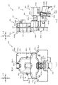
図3に示すように、パチンコ機10の背面側には、制御基板ユニット90,91と、裏パックユニット94とが主に備えられている。制御基板ユニット90は、主基板(主制御装置110)と音声ランプ制御基板(音声ランプ制御装置113)と表示制御基板(表示制御装置114)とが搭載されてユニット化されている。制御基板ユニット91は、払出制御基板(払出制御装置111)と発射制御基板(発射制御装置112)と電源基板(電源装置115)とカードユニット接続基板116とが搭載されてユニット化されている。
As shown in FIG. 3, the control board units 90 and 91 and the back pack unit 94 are mainly provided on the back side of the pachinko machine 10. The control board unit 90 is unitized by mounting a main board (main control device 110), a voice lamp control board (voice lamp control device 113), and a display control board (display control device 114). The control board unit 91 is unitized by mounting a payout control board (payout control device 111), a launch control board (launch control device 112), a power supply board (power supply device 115), and a card unit connection board 116.
裏パックユニット94は、保護カバー部を形成する裏パック92と払出ユニット93とがユニット化されている。また、各制御基板には、各制御を司る1チップマイコンとしてのMPU、各種機器との連絡をとるポート、各種抽選の際に用いられる乱数発生器、時間計数や同期を図る場合などに使用されるクロックパルス発生回路等が、必要に応じて搭載されている。
In the back pack unit 94, the back pack 92 forming the protective cover portion and the payout unit 93 are unitized. In addition, each control board is used for MPU as a one-chip microcomputer that controls each control, a port for contacting various devices, a random number generator used for various lottery, and for time counting and synchronization. A clock pulse generation circuit, etc. is installed as needed.
なお、主制御装置110、音声ランプ制御装置113及び表示制御装置114、払出制御装置111及び発射制御装置112、電源装置115、カードユニット接続基板116は、それぞれ基板ボックス100〜104に収納されている。基板ボックス100〜104は、ボックスベースと該ボックスベースの開口部を覆うボックスカバーとを備えており、そのボックスベースとボックスカバーとが互いに連結されて、各制御装置や各基板が収納される。
The main control device 110, the voice lamp control device 113 and the display control device 114, the payout control device 111 and the launch control device 112, the power supply device 115, and the card unit connection board 116 are housed in the board boxes 100 to 104, respectively. .. The board boxes 100 to 104 include a box base and a box cover that covers an opening of the box base, and the box base and the box cover are connected to each other to house each control device and each board.
また、基板ボックス100(主制御装置110)及び基板ボックス102(払出制御装置111及び発射制御装置112)は、ボックスベースとボックスカバーとを封印ユニット(図示せず)によって開封不能に連結(かしめ構造による連結)している。また、ボックスベースとボックスカバーとの連結部には、ボックスベースとボックスカバーとに亘って封印シール(図示せず)が貼着されている。この封印シールは、脆性な素材で構成されており、基板ボックス100,102を開封するために封印シールを剥がそうとしたり、基板ボックス100,102を無理に開封しようとすると、ボックスベース側とボックスカバー側とに切断される。よって、封印ユニット又は封印シールを確認することで、基板ボックス100,102が開封されたかどうかを知ることができる。
Further, in the board box 100 (main control device 110) and the board box 102 (payout control device 111 and launch control device 112), the box base and the box cover are connected by a sealing unit (not shown) so as not to be opened (caulking structure). (Consolidated by). Further, a sealing sticker (not shown) is attached to the connecting portion between the box base and the box cover over the box base and the box cover. This sealing sticker is made of a brittle material, and if the sealing sticker is to be peeled off in order to open the board boxes 100 and 102, or if the board boxes 100 and 102 are forcibly opened, the box base side and the box cover are used. Cut to the side. Therefore, by checking the sealing unit or the sealing seal, it is possible to know whether or not the substrate boxes 100 and 102 have been opened.
払出ユニット93は、裏パックユニット94の最上部に位置して上方に開口したタンク130と、タンク130の下方に連結され下流側に向けて緩やかに傾斜するタンクレール131と、タンクレール131の下流側に縦向きに連結されるケースレール132と、ケースレール132の最下流部に設けられ、払出モータ216(図4参照)の所定の電気的構成により球の払出を行う払出装置133とを備えている。タンク130には、遊技ホールの島設備から供給される球が逐次補給され、払出装置133により必要個数の球の払い出しが適宜行われる。タンクレール131には、当該タンクレール131に振動を付加するためのバイブレータ134が取り付けられている。
The payout unit 93 includes a tank 130 located at the uppermost portion of the back pack unit 94 and opened upward, a tank rail 131 connected below the tank 130 and gently inclined toward the downstream side, and a downstream of the tank rail 131. A case rail 132 vertically connected to the side and a payout device 133 provided at the most downstream portion of the case rail 132 and paying out balls by a predetermined electrical configuration of a payout motor 216 (see FIG. 4) are provided. ing. The tank 130 is sequentially replenished with balls supplied from the island equipment of the game hall, and the required number of balls is appropriately paid out by the payout device 133. A vibrator 134 for adding vibration to the tank rail 131 is attached to the tank rail 131.
また、払出制御装置111には状態復帰スイッチ120が設けられ、発射制御装置112には可変抵抗器の操作つまみ121が設けられ、電源装置115にはRAM消去スイッチ122が設けられている。状態復帰スイッチ120は、例えば、払出モータ216(図4参照)部の球詰まり等、払出エラーの発生時に球詰まりを解消(正常状態への復帰)するために操作される。操作つまみ121は、発射ソレノイドの発射力を調整するために操作される。RAM消去スイッチ122は、パチンコ機10を初期状態に戻したい場合に電源投入時に操作される。
Further, the payout control device 111 is provided with a state return switch 120, the launch control device 112 is provided with a variable resistor operation knob 121, and the power supply device 115 is provided with a RAM erase switch 122. The state return switch 120 is operated to clear the ball clogging (return to the normal state) when a payout error occurs, such as a ball clogging of the payout motor 216 (see FIG. 4). The operation knob 121 is operated to adjust the firing force of the firing solenoid. The RAM erase switch 122 is operated when the power is turned on when it is desired to return the pachinko machine 10 to the initial state.
次に、図4を参照して、本パチンコ機10の電気的構成について説明する。図4は、パチンコ機10の電気的構成を示すブロック図である。
Next, the electrical configuration of the pachinko machine 10 will be described with reference to FIG. FIG. 4 is a block diagram showing an electrical configuration of the pachinko machine 10.
主制御装置110には、演算装置である1チップマイコンとしてのMPU201が搭載されている。MPU201には、該MPU201により実行される各種の制御プログラムや固定値データを記憶したROM202と、そのROM202内に記憶される制御プログラムの実行に際して各種のデータ等を一時的に記憶するためのメモリであるRAM203と、そのほか、割込回路やタイマ回路、データ送受信回路などの各種回路が内蔵されている。主制御装置110では、MPU201によって、大当たり抽選や第1図柄表示装置37A,37B及び第3図柄表示装置81における表示の設定、第2図柄表示装置における表示結果の抽選といったパチンコ機10の主要な処理を実行する。
The main control device 110 is equipped with an MPU 201 as a one-chip microcomputer which is an arithmetic unit. The MPU 201 is a ROM 202 that stores various control programs and fixed value data executed by the MPU 201, and a memory for temporarily storing various data and the like when the control program stored in the ROM 202 is executed. A certain RAM 203 and various other circuits such as an interrupt circuit, a timer circuit, and a data transmission / reception circuit are built in. In the main control device 110, the MPU 201 is used to perform main processing of the pachinko machine 10 such as a jackpot lottery, display settings in the first symbol display devices 37A and 37B and the third symbol display device 81, and a lottery of display results in the second symbol display device. To execute.
なお、払出制御装置111や音声ランプ制御装置113などのサブ制御装置に対して動作を指示するために、主制御装置110から該サブ制御装置へ各種のコマンドがデータ送受信回路によって送信されるが、かかるコマンドは、主制御装置110からサブ制御装置へ一方向にのみ送信される。
In order to instruct the operation of the sub control device such as the payout control device 111 and the voice lamp control device 113, various commands are transmitted from the main control device 110 to the sub control device by the data transmission / reception circuit. Such a command is transmitted from the main control device 110 to the sub control device in only one direction.
RAM203は、各種エリア、カウンタ、フラグのほか、MPU201の内部レジスタの内容やMPU201により実行される制御プログラムの戻り先番地などが記憶されるスタックエリアと、各種のフラグおよびカウンタ、I/O等の値が記憶される作業エリア(作業領域)とを有している。なお、RAM203は、パチンコ機10の電源の遮断後においても電源装置115からバックアップ電圧が供給されてデータを保持(バックアップ)できる構成となっており、RAM203に記憶されるデータは、すべてバックアップされる。
The RAM 203 includes various areas, counters, flags, a stack area in which the contents of the internal registers of the MPU 201 and the return address of the control program executed by the MPU 201 are stored, various flags, counters, I / O, and the like. It has a work area (work area) in which values are stored. The RAM 203 has a configuration in which a backup voltage is supplied from the power supply device 115 to hold (back up) data even after the power of the pachinko machine 10 is cut off, and all the data stored in the RAM 203 is backed up. ..
停電などの発生により電源が遮断されると、その電源遮断時(停電発生時を含む。以下同様)のスタックポインタや、各レジスタの値がRAM203に記憶される。一方、電源投入時(停電解消による電源投入を含む。以下同様)には、RAM203に記憶される情報に基づいて、パチンコ機10の状態が電源遮断前の状態に復帰される。RAM203への書き込みはメイン処理(図示せず)によって電源遮断時に実行され、RAM203に書き込まれた各値の復帰は電源投入時の立ち上げ処理(図示せず)において実行される。なお、MPU201のNMI端子(ノンマスカブル割込端子)には、停電等の発生による電源遮断時に、停電監視回路252からの停電信号SG1が入力されるように構成されており、その停電信号SG1がMPU201へ入力されると、停電時処理としてのNMI割込処理(図示せず)が即座に実行される。
When the power supply is cut off due to the occurrence of a power failure or the like, the stack pointer at the time of the power failure (including the time when the power failure occurs; the same applies hereinafter) and the value of each register are stored in the RAM 203. On the other hand, when the power is turned on (including power on due to power failure elimination; the same applies hereinafter), the state of the pachinko machine 10 is restored to the state before the power was cut off based on the information stored in the RAM 203. Writing to the RAM 203 is executed by the main process (not shown) when the power is cut off, and restoration of each value written in the RAM 203 is executed in the start-up process (not shown) at the time of turning on the power. The NMI terminal (non-maskable interrupt terminal) of the MPU 201 is configured so that a power failure signal SG1 from the power failure monitoring circuit 252 is input when the power is cut off due to a power failure or the like, and the power failure signal SG1 is the MPU201. When input to, the NMI interrupt process (not shown) as the power failure process is immediately executed.
主制御装置110のMPU201には、アドレスバス及びデータバスで構成されるバスライン204を介して入出力ポート205が接続されている。入出力ポート205には、払出制御装置111、音声ランプ制御装置113、第1図柄表示装置37A,37B、第2図柄表示装置、第2図柄保留ランプ、特定入賞口65aの開閉板65b(図2参照)の下辺を軸として正面側に開閉駆動するための大開放口ソレノイドや電動役物を駆動するためのソレノイドなどからなるソレノイド209が接続され、MPU201は、入出力ポート205を介してこれらに対し各種コマンドや制御信号を送信する。
An input / output port 205 is connected to the MPU 201 of the main control device 110 via a bus line 204 composed of an address bus and a data bus. The input / output port 205 includes a payout control device 111, a voice lamp control device 113, a first symbol display device 37A, 37B, a second symbol display device, a second symbol hold lamp, and an opening / closing plate 65b of a specific winning opening 65a (FIG. 2). A solenoid 209 consisting of a large opening solenoid for driving the opening and closing and a solenoid for driving an electric accessory is connected to the front side with the lower side as an axis, and the MPU 201 is connected to these via the input / output port 205. It sends various commands and control signals to it.
また、入出力ポート205には、図示しないスイッチ群およびスライド位置検出センサSや回転位置検出センサRを含むセンサ群などからなる各種スイッチ208、電源装置115に設けられた後述のRAM消去スイッチ回路253が接続され、MPU201は各種スイッチ208から出力される信号や、RAM消去スイッチ回路253より出力されるRAM消去信号SG2に基づいて各種処理を実行する。
Further, the input / output port 205 includes various switches 208 including a switch group (not shown), a sensor group including a slide position detection sensor S and a rotation position detection sensor R, and a RAM erasing switch circuit 253 provided in the power supply device 115, which will be described later. Is connected, and the MPU 201 executes various processes based on the signals output from the various switches 208 and the RAM erase signal SG2 output from the RAM erase switch circuit 253.
払出制御装置111は、払出モータ216を駆動させて賞球や貸出球の払出制御を行うものである。演算装置であるMPU211は、そのMPU211により実行される制御プログラムや固定値データ等を記憶したROM212と、ワークメモリ等として使用されるRAM213とを有している。
The payout control device 111 drives the payout motor 216 to control the payout of prize balls and rented balls. The MPU 211, which is an arithmetic unit, has a ROM 212 that stores a control program and fixed value data executed by the MPU 211, and a RAM 213 that is used as a work memory or the like.
払出制御装置111のRAM213は、主制御装置110のRAM203と同様に、MPU211の内部レジスタの内容やMPU211により実行される制御プログラムの戻り先番地などが記憶されるスタックエリアと、各種のフラグおよびカウンタ、I/O等の値が記憶される作業エリア(作業領域)とを有している。RAM213は、パチンコ機10の電源の遮断後においても電源装置115からバックアップ電圧が供給されてデータを保持(バックアップ)できる構成となっており、RAM213に記憶されるデータは、すべてバックアップされる。なお、主制御装置110のMPU201と同様、MPU211のNMI端子にも、停電等の発生による電源遮断時に停電監視回路252から停電信号SG1が入力されるように構成されており、その停電信号SG1がMPU211へ入力されると、停電時処理としてのNMI割込処理(図示せず)が即座に実行される。
The RAM 213 of the payout control device 111, like the RAM 203 of the main control device 110, has a stack area in which the contents of the internal registers of the MPU 211 and the return address of the control program executed by the MPU 211 are stored, and various flags and counters. It has a work area (work area) in which values such as, I / O, etc. are stored. The RAM 213 has a configuration in which a backup voltage is supplied from the power supply device 115 to hold (back up) data even after the power supply of the pachinko machine 10 is cut off, and all the data stored in the RAM 213 is backed up. Similar to the MPU 201 of the main control device 110, the NMI terminal of the MPU 211 is also configured so that the power failure signal SG1 is input from the power failure monitoring circuit 252 when the power is cut off due to the occurrence of a power failure or the like. When input to the MPU211, an NMI interrupt process (not shown) as a power failure process is immediately executed.
払出制御装置111のMPU211には、アドレスバス及びデータバスで構成されるバスライン214を介して入出力ポート215が接続されている。入出力ポート215には、主制御装置110や払出モータ216、発射制御装置112などがそれぞれ接続されている。また、図示はしないが、払出制御装置111には、払い出された賞球を検出するための賞球検出スイッチが接続されている。なお、該賞球検出スイッチは、払出制御装置111に接続されるが、主制御装置110には接続されていない。
An input / output port 215 is connected to the MPU 211 of the payout control device 111 via a bus line 214 composed of an address bus and a data bus. The main control device 110, the payout motor 216, the launch control device 112, and the like are connected to the input / output port 215, respectively. Further, although not shown, the payout control device 111 is connected to a prize ball detection switch for detecting the paid out prize balls. The prize ball detection switch is connected to the payout control device 111, but is not connected to the main control device 110.
発射制御装置112は、主制御装置110により球の発射の指示がなされた場合に、操作ハンドル51の回動操作量に応じた球の打ち出し強さとなるよう球発射ユニット112aを制御するものである。球発射ユニット112aは、図示しない発射ソレノイドおよび電磁石を備えており、その発射ソレノイドおよび電磁石は、所定条件が整っている場合に駆動が許可される。具体的には、遊技者が操作ハンドル51に触れていることをタッチセンサ51aにより検出し、球の発射を停止させるための発射停止スイッチ51bがオフ(操作されていないこと)を条件に、操作ハンドル51の回動操作量(回動位置)に対応して発射ソレノイドが励磁され、操作ハンドル51の操作量に応じた強さで球が発射される。
The launch control device 112 controls the ball launch unit 112a so that when the main control device 110 gives an instruction to launch the ball, the launch strength of the ball corresponds to the amount of rotation of the operation handle 51. .. The ball launch unit 112a includes a launch solenoid and an electromagnet (not shown), and the launch solenoid and the electromagnet are allowed to be driven when predetermined conditions are met. Specifically, the touch sensor 51a detects that the player is touching the operation handle 51, and the operation is performed on condition that the launch stop switch 51b for stopping the launch of the ball is off (not operated). The firing solenoid is excited in response to the rotation operation amount (rotation position) of the handle 51, and the ball is launched with a strength corresponding to the operation amount of the operation handle 51.
音声ランプ制御装置113は、音声出力装置(図示しないスピーカなど)226における音声の出力、ランプ表示装置(電飾部29〜33、表示ランプ34など)227における点灯および消灯の出力、変動演出(変動表示)や予告演出といった表示制御装置114で行われる第3図柄表示装置81の表示態様の設定などを制御するものである。演算装置であるMPU221は、そのMPU221により実行される制御プログラムや固定値データ等を記憶したROM222と、ワークメモリ等として使用されるRAM223とを有している。
The audio lamp control device 113 is an audio output in an audio output device (speaker, etc. not shown) 226, an output of lighting and extinguishing in a lamp display device (illumination units 29 to 33, indicator lamp 34, etc.) 227, and a variation effect (variation). It controls the setting of the display mode of the third symbol display device 81 performed by the display control device 114 such as the display) and the advance notice effect. The arithmetic unit MPU 221 has a ROM 222 that stores a control program and fixed value data executed by the MPU 221 and a RAM 223 that is used as a work memory or the like.
音声ランプ制御装置113のMPU221には、アドレスバス及びデータバスで構成されるバスライン224を介して入出力ポート225が接続されている。入出力ポート225には、主制御装置110、表示制御装置114、音声出力装置226、ランプ表示装置227、その他装置228、枠ボタン22などがそれぞれ接続されている。その他装置228には駆動モータ648,820、ソレノイド651等が含まれる。
An input / output port 225 is connected to the MPU 221 of the voice lamp control device 113 via a bus line 224 composed of an address bus and a data bus. A main control device 110, a display control device 114, an audio output device 226, a lamp display device 227, other devices 228, a frame button 22, and the like are connected to the input / output port 225, respectively. Other devices 228 include drive motors 648, 820, solenoid 651, and the like.
音声ランプ制御装置113は、主制御装置110から受信した各種のコマンド(変動パターンコマンド、停止種別コマンド等)に基づいて、第3図柄表示装置81の表示態様を決定し、決定した表示態様をコマンド(表示用変動パターンコマンド、表示用停止種別コマンド等)によって表示制御装置114へ通知する。また、音声ランプ制御装置113は、枠ボタン22からの入力を監視し、遊技者によって枠ボタン22が操作された場合は、第3図柄表示装置81で表示されるステージを変更したり、スーパーリーチ時の演出内容を変更したりするように、表示制御装置114へ指示する。ステージが変更される場合は、変更後のステージに応じた背面画像を第3図柄表示装置81に表示させるべく、変更後のステージに関する情報を含めた背面画像変更コマンドを表示制御装置114へ送信する。ここで、背面画像とは、第3図柄表示装置81に表示させる主要な画像である第3図柄の背面側に表示される画像のことである。表示制御装置114は、この音声ランプ制御装置113から送信されるコマンドに従って、第3図柄表示装置81に各種の画像を表示する。
The voice lamp control device 113 determines the display mode of the third symbol display device 81 based on various commands (variation pattern command, stop type command, etc.) received from the main control device 110, and commands the determined display mode. The display control device 114 is notified by (display fluctuation pattern command, display stop type command, etc.). Further, the voice lamp control device 113 monitors the input from the frame button 22, and when the frame button 22 is operated by the player, the stage displayed on the third symbol display device 81 can be changed or the super reach can be changed. The display control device 114 is instructed to change the effect content of the time. When the stage is changed, a rear image change command including information about the changed stage is transmitted to the display control device 114 in order to display the rear image corresponding to the changed stage on the third symbol display device 81. .. Here, the back image is an image displayed on the back side of the third symbol, which is a main image to be displayed on the third symbol display device 81. The display control device 114 displays various images on the third symbol display device 81 according to a command transmitted from the voice lamp control device 113.
また、音声ランプ制御装置113は、表示制御装置114から第3図柄表示装置81の表示内容を表すコマンド(表示コマンド)を受信する。音声ランプ制御装置113では、表示制御装置114から受信した表示コマンドに基づき、第3図柄表示装置81の表示内容に合わせて、その表示内容に対応する音声を音声出力装置226から出力し、また、その表示内容に対応させてランプ表示装置227の点灯および消灯を制御する。
Further, the voice lamp control device 113 receives a command (display command) indicating the display contents of the third symbol display device 81 from the display control device 114. Based on the display command received from the display control device 114, the voice lamp control device 113 outputs the voice corresponding to the display content according to the display content of the third symbol display device 81 from the voice output device 226, and also outputs the voice corresponding to the display content. The lighting and extinguishing of the lamp display device 227 are controlled according to the display content.
表示制御装置114は、音声ランプ制御装置113及び第3図柄表示装置81が接続され、音声ランプ制御装置113より受信したコマンドに基づいて、第3図柄表示装置81における第3図柄の変動演出などの表示を制御するものである。また、表示制御装置114は、第3図柄表示装置81の表示内容を通知する表示コマンドを適宜音声ランプ制御装置113へ送信する。音声ランプ制御装置113は、この表示コマンドによって示される表示内容にあわせて音声出力装置226から音声を出力することで、第3図柄表示装置81の表示と音声出力装置226からの音声出力とをあわせることができる。
In the display control device 114, the voice lamp control device 113 and the third symbol display device 81 are connected, and based on the command received from the voice lamp control device 113, the third symbol variation effect of the third symbol display device 81 and the like are performed. It controls the display. Further, the display control device 114 appropriately transmits a display command for notifying the display content of the third symbol display device 81 to the voice lamp control device 113. The voice lamp control device 113 outputs voice from the voice output device 226 according to the display content indicated by this display command, thereby matching the display of the third symbol display device 81 with the voice output from the voice output device 226. be able to.
電源装置115は、パチンコ機10の各部に電源を供給するための電源部251と、停電等による電源遮断を監視する停電監視回路252と、RAM消去スイッチ122(図3参照)が設けられたRAM消去スイッチ回路253とを有している。電源部251は、図示しない電源経路を通じて、各制御装置110〜114等に対して各々に必要な動作電圧を供給する装置である。その概要としては、電源部251は、外部より供給される交流24ボルトの電圧を取り込み、各種スイッチ208などの各種スイッチや、ソレノイド209などのソレノイド、モータ等を駆動するための12ボルトの電圧、ロジック用の5ボルトの電圧、RAMバックアップ用のバックアップ電圧などを生成し、これら12ボルトの電圧、5ボルトの電圧及びバックアップ電圧を各制御装置110〜114等に対して必要な電圧を供給する。
The power supply device 115 is provided with a power supply unit 251 for supplying power to each part of the pachinko machine 10, a power failure monitoring circuit 252 for monitoring power failure due to a power failure, and a RAM erasing switch 122 (see FIG. 3). It has an erasing switch circuit 253. The power supply unit 251 is a device that supplies the required operating voltage to each of the control devices 110 to 114 and the like through a power supply path (not shown). As an outline, the power supply unit 251 takes in an AC 24 volt voltage supplied from the outside, and has a 12 volt voltage for driving various switches such as various switches 208, a solenoid such as a solenoid 209, and a motor. A 5 volt voltage for logic, a backup voltage for RAM backup, and the like are generated, and these 12 volt voltage, 5 volt voltage, and backup voltage are supplied to each control device 110 to 114 and the like.
停電監視回路252は、停電等の発生による電源遮断時に、主制御装置110のMPU201及び払出制御装置111のMPU211の各NMI端子へ停電信号SG1を出力するための回路である。停電監視回路252は、電源部251から出力される最大電圧である直流安定24ボルトの電圧を監視し、この電圧が22ボルト未満になった場合に停電(電源断、電源遮断)の発生と判断して、停電信号SG1を主制御装置110及び払出制御装置111へ出力する。停電信号SG1の出力によって、主制御装置110及び払出制御装置111は、停電の発生を認識し、NMI割込処理を実行する。なお、電源部251は、直流安定24ボルトの電圧が22ボルト未満になった後においても、NMI割込処理の実行に充分な時間の間、制御系の駆動電圧である5ボルトの電圧の出力を正常値に維持するように構成されている。よって、主制御装置110及び払出制御装置111は、NMI割込処理(図示せず)を正常に実行し完了することができる。
The power failure monitoring circuit 252 is a circuit for outputting a power failure signal SG1 to each NMI terminal of the MPU 201 of the main control device 110 and the MPU 211 of the payout control device 111 when the power is cut off due to the occurrence of a power failure or the like. The power failure monitoring circuit 252 monitors the DC stable 24 volt voltage, which is the maximum voltage output from the power supply unit 251 and determines that a power failure (power failure, power failure) has occurred when this voltage becomes less than 22 volts. Then, the power failure signal SG1 is output to the main control device 110 and the payout control device 111. By the output of the power failure signal SG1, the main control device 110 and the payout control device 111 recognize the occurrence of the power failure and execute the NMI interrupt process. The power supply unit 251 outputs a voltage of 5 volts, which is the drive voltage of the control system, for a sufficient period of time to execute the NMI interrupt process even after the voltage of DC stable 24 volts becomes less than 22 volts. Is configured to maintain a normal value. Therefore, the main control device 110 and the payout control device 111 can normally execute and complete the NMI interrupt process (not shown).
RAM消去スイッチ回路253は、RAM消去スイッチ122(図3参照)が押下された場合に、主制御装置110へ、バックアップデータをクリアさせるためのRAM消去信号SG2を出力するための回路である。主制御装置110は、パチンコ機10の電源投入時に、RAM消去信号SG2を入力した場合に、バックアップデータをクリアすると共に、払出制御装置111においてバックアップデータをクリアさせるための払出初期化コマンドを払出制御装置111に対して送信する。
The RAM erase switch circuit 253 is a circuit for outputting the RAM erase signal SG2 for clearing the backup data to the main control device 110 when the RAM erase switch 122 (see FIG. 3) is pressed. When the RAM erase signal SG2 is input when the power of the pachinko machine 10 is turned on, the main control device 110 clears the backup data, and the payout control device 111 issues a payout initialization command for clearing the backup data. It transmits to the device 111.
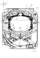
図5及び図6を参照して、第1実施形態における遊技盤13のベース板に配設される入賞口ユニット930及び送球ユニット970について説明する。なお、図5及び図6の説明では図2を適宜参照する。
The winning opening unit 930 and the ball throwing unit 970 arranged on the base plate of the game board 13 in the first embodiment will be described with reference to FIGS. 5 and 6. In the description of FIGS. 5 and 6, FIG. 2 will be referred to as appropriate.
図5は、遊技盤13の分解斜視正面図である。なお、図5では、ベース板60に配設される入賞口ユニット930及び送球ユニット970以外のユニット(例えば、センターフレーム86(図2参照)など)の図示が省略される。
FIG. 5 is an exploded perspective front view of the game board 13. Note that in FIG. 5, the illustration of units other than the winning opening unit 930 and the ball throwing unit 970 (for example, the center frame 86 (see FIG. 2)) arranged on the base plate 60 is omitted.
図5に示すように、ベース板60には、センターフレーム86(図2参照)が取り付けられる中央開口の重力方向下側(図5下側)にベース板60の厚み方向に貫通する貫通孔60aがルータ加工によって形成される。
As shown in FIG. 5, in the base plate 60, a through hole 60a penetrating in the thickness direction of the base plate 60 on the lower side in the gravity direction (lower side in FIG. 5) of the central opening to which the center frame 86 (see FIG. 2) is attached. Is formed by router processing.
貫通孔60aは、後述する正面ユニット940の正面視における外形よりも若干小さく形成され、内側に正面ユニット940に配設される駆動ユニット960及び特定入賞口ユニット950が挿入される。
The through hole 60a is formed to be slightly smaller than the outer shape of the front unit 940 in front view, which will be described later, and the drive unit 960 and the specific winning opening unit 950 arranged in the front unit 940 are inserted inside.
ベース板60には、遊技領域(正面)側から入賞口ユニット930が配設され、遊技領域と反対(背面)側から送球ユニット970が配設され、それぞれタッピングネジ等により締結固定される。なお、入賞口ユニット930及び送球ユニット970の詳細な構成については後述する。
The winning opening unit 930 is arranged on the base plate 60 from the game area (front) side, and the ball throwing unit 970 is arranged from the opposite (back) side of the game area, and each is fastened and fixed by a tapping screw or the like. The detailed configuration of the winning opening unit 930 and the throwing unit 970 will be described later.
図6は、図2のVI−VI線における遊技盤13の断面図である。図6では、組立状態における入賞口ユニット930及び送球ユニット970の配置について図示される。
FIG. 6 is a cross-sectional view of the game board 13 in the VI-VI line of FIG. FIG. 6 illustrates the arrangement of the winning opening unit 930 and the throwing unit 970 in the assembled state.
図6に示すように、正面ユニット940及び送球ユニット970の各通路の連結は、前後方向(図6左右方向)に当接した状態とされると共に、送球ユニット970に形成される凸部が、正面ユニット940に形成される突部に挿入される。
As shown in FIG. 6, the passages of the front unit 940 and the throwing unit 970 are connected to each other in the front-rear direction (horizontal direction in FIG. 6), and the convex portion formed on the throwing unit 970 is formed. It is inserted into a protrusion formed on the front unit 940.
詳しく説明すると、第1送球部942gと流入口982dとは、第1送球部942gに形成される第1凹欠部942g1の内側に流入口982dに形成される第2突起982d1が配置される。また、第2送球部942cと側壁部981bとは、第2送球部942cに形成される第2凹欠部942c1の内側に、側壁部981bに形成される突起981b1が配置される。これにより、ベース板60に組み付ける際の正面ユニット940及び送球ユニット970の位置合わせを容易に行うことができる。
More specifically, the first throwing portion 942g and the inflow port 982d have a second protrusion 982d1 formed at the inflow port 982d inside the first recessed portion 942g1 formed in the first throwing portion 942g. Further, in the second throwing portion 942c and the side wall portion 981b, the protrusion 981b1 formed on the side wall portion 981b is arranged inside the second recessed portion 942c1 formed in the second throwing portion 942c. This makes it possible to easily align the front unit 940 and the ball throwing unit 970 when assembling to the base plate 60.
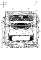
次いで、図7及び図8を参照して、送球ユニット970の全体構成について説明する。図7(a)は、送球ユニット970の正面図であり、図7(b)は、送球ユニット970の側面図である。図8(a)は、送球ユニット970の分解斜視正面図であり、図8(b)は、送球ユニット970の分解斜視背面図である。
Next, the overall configuration of the throwing unit 970 will be described with reference to FIGS. 7 and 8. FIG. 7A is a front view of the ball throwing unit 970, and FIG. 7B is a side view of the ball throwing unit 970. FIG. 8A is an exploded perspective front view of the throwing unit 970, and FIG. 8B is an exploded perspective rear view of the throwing unit 970.
図7及び図8に示すように、送球ユニット970は、遊技者側(遊技領域側)に配設され内部に遊技球を挿通可能な空間を備える振分けユニット980と、その振分けユニット980の遊技領域と反対側に配設される通路ユニット990とを備えて形成される。
As shown in FIGS. 7 and 8, the throwing unit 970 is a distribution unit 980 arranged on the player side (game area side) and provided with a space through which the game ball can be inserted, and the game area of the distribution unit 980. It is formed with a passage unit 990 arranged on the opposite side to the above.
振分けユニット980は、上述した入賞口ユニット930の第1入賞口64及び第2入賞口140と連なる開口(流入口982d及び側壁部981b)を備えており、その開口(流入口982d及び側壁部981b)から第1入賞口64及び第2入賞口140の介して遊技領域と反対側に送球される遊技球を内部に受け入れることができる。なお、振分けユニット980についての詳しい説明は後述する。
The distribution unit 980 is provided with openings (inflow port 982d and side wall portion 981b) that are connected to the first winning port 64 and the second winning port 140 of the above-mentioned winning port unit 930, and the openings (inflow port 982d and side wall portion 981b) are provided. ) To the side opposite to the game area through the first winning opening 64 and the second winning opening 140 can be received inside. A detailed description of the distribution unit 980 will be described later.
通路ユニット990は、振分けユニット980の重力方向一側(重力方向下側)に配設される。通路ユニット990は、振分けユニット980との対向面に複数の開口(第1挿通孔991a〜第2挿通孔991dを備えており、振分けユニット980の内部を送球される遊技球をその開口から受け入れることができる。なお、通路ユニット990についての詳しい説明は後述する。
The passage unit 990 is arranged on one side in the gravity direction (lower side in the gravity direction) of the distribution unit 980. The passage unit 990 is provided with a plurality of openings (first insertion holes 991a to second insertion holes 991d) on the surface facing the distribution unit 980, and receives a game ball thrown inside the distribution unit 980 from the openings. A detailed description of the passage unit 990 will be described later.
次いで、図9から図12を参照して、振分けユニット980の構成について詳細な説明をする。図9(a)は、振分けユニット980の正面図であり、図9(b)は、振分けユニット980の側面図である。図10は、振分けユニット980の分解斜視正面図であり、図11は、振分けユニット980の分解斜視背面図である。図12(a)は、図9(a)のXIIa−XIIa線における振分けユニット980の断面図であり、図12(b)は、図12(a)のXIIb−XIIbにおける振分けユニット980の断面図である。
Next, the configuration of the distribution unit 980 will be described in detail with reference to FIGS. 9 to 12. 9 (a) is a front view of the distribution unit 980, and FIG. 9 (b) is a side view of the distribution unit 980. FIG. 10 is an exploded perspective front view of the distribution unit 980, and FIG. 11 is an exploded perspective rear view of the distribution unit 980. 12 (a) is a cross-sectional view of the sorting unit 980 in the line XIIa-XIIa of FIG. 9 (a), and FIG. 12 (b) is a cross-sectional view of the sorting unit 980 in the XIIb-XIIb of FIG. 12 (a). Is.
図9から図12に示すように、振分けユニット980は、背面ベース985と、その背面ベース985の遊技者側に配設される正面ベース981と、その正面ベース981と背面ベースとの間に回転可能な状態で配設される振分け部983と、背面ベース985の背面側に振分け部983と対応する位置に配設されるカバー部材987とを主に備えて形成される。
As shown in FIGS. 9 to 12, the distribution unit 980 rotates between the back base 985, the front base 981 arranged on the player side of the back base 985, and the front base 981 and the back base. A distribution portion 983 arranged in a possible state and a cover member 987 arranged at a position corresponding to the distribution portion 983 on the back surface side of the back surface base 985 are mainly provided.
背面ベース985は、有色半透明(本実施形態では、青色)の樹脂材料から形成され、板状体に形成されるベース部985aと、そのベース部985aの厚み方向に貫通する複数の開口(開口985b〜985g)と、その複数の開口の重力方向他側(重力方向上側)に凹設される凹部985hと、その凹部985hの反対面から突出する収容部986b及び突設部986eとを主に備えて形成される。
The back base 985 is formed of a colored translucent (blue in this embodiment) resin material, and has a base portion 985a formed in a plate-like body and a plurality of openings (openings) penetrating the base portion 985a in the thickness direction. 985b to 985g), a recess 985h recessed on the other side (upper side in the gravity direction) of the plurality of openings in the gravity direction, and a housing portion 986b and a protrusion 986e protruding from the opposite surface of the recess 985h. Formed in preparation.
ベース部985aは、正面視縦長矩形に形成され、その外縁部に円形状に貫通する複数の締結孔986c及び986dと、正面ベース981側と反対側に重力方向一側に向かって傾斜する傾斜面986aとを備えて形成される。締結孔986cは、後述する正面ベース981を挿通したネジを螺合する孔である。これにより、正面ベース981及び背面ベース985を締結固定することができる。また、締結孔986dは、後述する通路ユニット990を挿通するネジを螺合する孔である。これにより、背面ベース985(振分けユニット980)及び通路ユニット990を締結固定することができる。
The base portion 985a is formed in a vertically long rectangular shape when viewed from the front, and has a plurality of fastening holes 986c and 986d penetrating in a circular shape on the outer edge thereof, and an inclined surface inclined toward one side in the direction of gravity opposite to the front base 981 side. Formed with 986a. The fastening hole 986c is a hole for screwing a screw through which the front base 981 described later is inserted. Thereby, the front base 981 and the back base 985 can be fastened and fixed. Further, the fastening hole 986d is a hole for screwing a screw through which the passage unit 990, which will be described later, is inserted. As a result, the back base 985 (distribution unit 980) and the aisle unit 990 can be fastened and fixed.
傾斜面986aは、後述する開口985b〜985fの重力方向他側の一部と重なる位置に形成される。また、傾斜面986aは、正面ベース981及び背面ベース985が組み合わされた状態において、正面ベース981の傾斜部982bと対向する位置に形成される。これにより、重力方向に流下する遊技球の流下方向を開口985b〜985f側に案内することができる。その結果、遊技球を開口985b〜985fに流入させやすくできる。
The inclined surface 986a is formed at a position overlapping a part of the openings 985b to 985f described later on the other side in the gravity direction. Further, the inclined surface 986a is formed at a position facing the inclined portion 982b of the front base 981 in a state where the front base 981 and the back base 985 are combined. Thereby, the flow direction of the game ball flowing down in the gravity direction can be guided to the openings 985b to 985f side. As a result, the game ball can be easily flowed into the openings 985b to 985f.
凹部985hは、正面ベース981と反対側(図9(b)紙面手前側)に向かって凹設されると共に、ベース部985aの短手方向(図9(b)左右方向)略中央位置に形成される。また、凹部985hは、内側に後述する振分け部983の一部を収容可能な大きさに形成されると共に、底面に円環状に突出する軸受部985jを備える。軸受部985jは、振分け部983を軸支する軸部材988aの一端が挿入される孔であり、軸部材988aの外径よりも大きい内径に形成される。
The recess 985h is recessed toward the side opposite to the front base 981 (the front side of the paper surface in FIG. 9B), and is formed at a substantially central position in the lateral direction (horizontal direction in FIG. 9B) of the base portion 985a. Will be done. Further, the recess 985h is formed in a size capable of accommodating a part of the distribution portion 983 described later on the inside, and is provided with a bearing portion 985j protruding in an annular shape on the bottom surface. The bearing portion 985j is a hole into which one end of the shaft member 988a that pivotally supports the distribution portion 983 is inserted, and is formed to have an inner diameter larger than the outer diameter of the shaft member 988a.
開口985b及び開口985cは、それぞれベース部985aの短手方向両端部に形成されるとともに、内縁の寸法が遊技球の直径よりも大きく設定される。また、開口985b及び開口985cは、重力方向一側(重力方向下側)の内面が正面ベース981側と反対側に向かうにつれて下降傾斜して形成される。これにより、正面ベース981側から流入する遊技球を正面ベース981側と反対側に転動させることができる。
The openings 985b and 985c are formed at both ends of the base portion 985a in the lateral direction, and the size of the inner edge is set to be larger than the diameter of the game ball. Further, the openings 985b and 985c are formed so as to be inclined downward as the inner surface on one side in the gravity direction (lower side in the gravity direction) is directed toward the side opposite to the front base 981 side. As a result, the game ball flowing in from the front base 981 side can be rolled to the side opposite to the front base 981 side.
開口985dは、ベース部985aの短手方向(図9(b)左右方向)略中央位置に形成され、重力方向(図9(b)上下方向)における位置が開口985b及び開口985cと略同一の位置に設定される。また、開口985dは、開口985b及び開口985cと同様に、重力方向一側(重力方向下側)の内面が正面ベース981側と反対側に向かうにつれて下降傾斜して形成される。これにより、正面ベース981側から流入する遊技球を正面ベース981側と反対側に転動させることができる。
The opening 985d is formed at a substantially central position in the lateral direction (FIG. 9 (b) left-right direction) of the base portion 985a, and the position in the gravity direction (FIG. 9 (b) vertical direction) is substantially the same as the opening 985b and the opening 985c. Set to position. Further, the opening 985d is formed so as to be inclined downward as the inner surface on one side in the gravity direction (lower side in the gravity direction) is directed toward the side opposite to the front base 981 side, similarly to the openings 985b and 985c. As a result, the game ball flowing in from the front base 981 side can be rolled to the side opposite to the front base 981 side.
開口985eは、開口985b及び開口985dの間に形成され、開口985fは、開口985c及び開口985dの間に形成される。また、開口985e,985fは、正面ベース981側に開口する空間の流入通路985e1,985f1と、正面ベース981側と反対側に開口する空間の排出通路985e3,985f3と、重力方向に延設され流入通路985e1,985f1及び排出通路985e3,985f3を連通する中間通路985e2,985f2と,を主に備えて形成される。
The opening 985e is formed between the openings 985b and 985d, and the opening 985f is formed between the openings 985c and 985d. Further, the openings 985e and 985f are extended in the direction of gravity and flow into the inflow passages 985e1,985f1 in the space opened on the front base 981 side and the discharge passages 985e3 and 985f3 in the space opened on the opposite side to the front base 981 side. It is mainly provided with intermediate passages 985e2, 985f2 that communicate with the passages 985e1,985f1 and the discharge passages 985e3,985f3.
流入通路985e1,985f1は、後述する正面ベース981と背面ベース985との対向間に形成される第1通路TR1及び第2通路TR2に連結されると共に、遊技球が通過可能な大きさに形成される。これにより、第1通路TR1及び第2通路を流下する遊技球を流入通路985e1,985f1に流入させることができる。
The inflow passages 985e1 and 985f1 are connected to the first passage TR1 and the second passage TR2 formed between the front base 981 and the back base 985, which will be described later, and are formed in a size that allows the game ball to pass through. To. As a result, the game balls flowing down the first passage TR1 and the second passage can flow into the inflow passages 985e1 and 985f1.
中間通路985e2,985f2は、重力方向に延設して形成され、重力方向他側(重力方向上側)が流入通路985e1,985f1に連通されると共に、遊技球が通過可能な大きさに形成される。これにより、流入通路985e1,985f1を通過する遊技球を中間通路985e2,985f2に流入させることができる。
The intermediate passages 985e2 and 985f2 are formed so as to extend in the gravity direction, and the other side in the gravity direction (upper side in the gravity direction) is communicated with the inflow passage 985e1,985f1 and is formed in a size that allows the game ball to pass through. .. As a result, the game ball passing through the inflow passage 985e1,985f1 can flow into the intermediate passage 985e2,985f2.
また、中間通路985e2,985f2には、遊技球の送球方向(重力方向)と略直交する方向に凹設される凹設部985f4が形成される。凹設部985f4は、その内側に後述する検出装置SE3を配設するための切り欠きであり、背面視において検出装置SE3の外形と略同一に設定される。これにより、検出装置SE3をベース部985aの背面側(正面ベース981と反対側)から挿入して配設することができる。
Further, in the intermediate passages 985e2 and 985f2, recessed portions 985f4 are formed which are recessed in a direction substantially orthogonal to the throwing direction (gravity direction) of the game ball. The recessed portion 985f4 is a notch for disposing the detection device SE3 described later inside the recessed portion 985f4, and is set substantially the same as the outer shape of the detection device SE3 in rear view. As a result, the detection device SE3 can be inserted and arranged from the back side (opposite side to the front base 981) of the base portion 985a.
検出装置SE3は、遊技球の通過を検知する装置であり、その厚み方向に遊技球よりも若干大きい内径の検出孔SE1aが貫通形成される。検出孔SE1aは、背面視横長矩形の状態で配設される検出装置SE3の長手方向のどちらか一方または他方に偏って形成されており、検出孔SE1aが形成されていない長手方向のどちらか他方または一方に検出装置SE3を制御する検出基板SE1bが配設される。
The detection device SE3 is a device that detects the passage of the game ball, and a detection hole SE1a having an inner diameter slightly larger than that of the game ball is formed through the detection device SE1a in the thickness direction thereof. The detection hole SE1a is formed unevenly in either one or the other of the longitudinal direction of the detection device SE3 arranged in a horizontally long rectangular shape in the rear view, and the detection hole SE1a is not formed in either of the longitudinal directions. Alternatively, a detection board SE1b that controls the detection device SE3 is arranged on one side.
本実施形態では、検出装置SE3により遊技球の通過が検知されると、5個の賞球が払い出されると共に、第1図柄の抽選が実行される。この抽選に対応して、第3図柄表示装置81で第3図柄の変動表示が実行される。
In the present embodiment, when the detection device SE3 detects the passage of the game ball, five prize balls are paid out and the lottery of the first symbol is executed. In response to this lottery, the third symbol display device 81 executes the variable display of the third symbol.
また、検出装置SE3は、検出孔SE1aの軸方向が中間通路985e2,985f2の延設方向に平行に設定されると共に、検出孔SE1aの内部空間と中間通路985e2,985f2の空間とが略一致する位置に配置される。これにより、遊技球が中間通路985e2,985f2の重力方向他側(重力方向上側)から重力方向一側(重力方向下側)に流下する場合に、検出装置SE3の検出孔SE1aを通過させることができる。これにより、第1通路TR1及び第2通路TR2を通過する遊技球を検出することができる。
Further, in the detection device SE3, the axial direction of the detection hole SE1a is set parallel to the extension direction of the intermediate passage 985e2, 985f2, and the internal space of the detection hole SE1a and the space of the intermediate passage 985e2, 985f2 substantially coincide with each other. Placed in position. As a result, when the game ball flows down from the other side in the gravity direction (upper side in the gravity direction) to the one side in the gravity direction (lower side in the gravity direction) in the intermediate passages 985e2 and 985f2, it can pass through the detection hole SE1a of the detection device SE3. it can. Thereby, the game ball passing through the first passage TR1 and the second passage TR2 can be detected.
また、検出装置SE3は、検出孔SE1aの軸方向が重力方向と平行に形成されるので、遊技球を検出孔SE1aに送球する際に、遊技球の自重を利用しやすくできる。その結果、遊技球が中間通路985e2,985f2及び検出孔SE1aとの連結部分に引っ掛ることを抑制できる。
Further, since the detection device SE3 is formed so that the axial direction of the detection hole SE1a is parallel to the direction of gravity, the weight of the game ball can be easily used when the game ball is sent to the detection hole SE1a. As a result, it is possible to prevent the game ball from being caught in the connecting portion between the intermediate passages 985e2 and 985f2 and the detection hole SE1a.
凹設部985e4,985f4は、流入通路985e1,985f1及び排出通路985e3,985f3の空間と連なって形成される。即ち、中間通路985e2,985f2は、検出装置SE3を利用して形成される。これにより、中間通路985e2,985f2の重力方向の長さ寸法が大きくなることを抑制できる。その結果、背面ベース985が重力方向に大型化することを抑制できる。
The recessed portions 985e4, 985f4 are formed so as to be connected to the spaces of the inflow passage 985e1,985f1 and the discharge passage 985e3,985f3. That is, the intermediate passages 985e2 and 985f2 are formed by using the detection device SE3. As a result, it is possible to suppress an increase in the length dimension of the intermediate passages 985e2 and 985f2 in the gravity direction. As a result, it is possible to prevent the back base 985 from becoming larger in the direction of gravity.
排出通路985e3,985f3は、中間通路985e2,985f2の重力方向一側(重力方向下側)に連結されると共に、遊技球が通過可能な大きさに形成される。また、排出通路985e3,985f3は、振分けユニット980及び通路ユニット990が組み合わされた状態において、後述する通路ユニット990の第3挿通孔991c及び第4挿通孔991dに連結される。これにより、中間通路985e2,985f2を通過する遊技球を、排出通路985e3,985f3に流入させることができると共に、その空間を通過させて通路ユニット990に送球できる。
The discharge passages 985e3 and 985f3 are connected to one side in the gravity direction (lower side in the gravity direction) of the intermediate passages 985e2 and 985f2, and are formed in a size that allows the game ball to pass through. Further, the discharge passages 985e3 and 985f3 are connected to the third insertion hole 991c and the fourth insertion hole 991d of the passage unit 990, which will be described later, in a state where the distribution unit 980 and the passage unit 990 are combined. As a result, the game ball passing through the intermediate passage 985e2, 985f2 can be made to flow into the discharge passage 985e3, 985f3, and can be passed through the space and sent to the passage unit 990.
開口985gは、開口985dの重力方向一側(重力方向下側)に形成される。また、開口985gは、開口985dと同様に、重力方向一側(重力方向下側)の内面が正面ベース981側と反対側に向かうにつてれて下降傾斜して形成される。これにより、正面ベース981側から流入する遊技球を正面ベース981と反対側に転動させることができる。
The opening 985g is formed on one side of the opening 985d in the direction of gravity (lower side in the direction of gravity). Further, the opening 985g is formed so that the inner surface on one side in the gravity direction (lower side in the gravity direction) is inclined downward toward the side opposite to the front base 981 side, similarly to the opening 985d. As a result, the game ball flowing in from the front base 981 side can be rolled to the opposite side to the front base 981.
流入通路985e1,985f1は、後述する正面ベース981と背面ベース985との対向間に形成される第1通路TR1及び第2通路TR2に連結されると共に、遊技球が通過可能な大きさに形成される。これにより、第1通路TR1及び第2通路TR2を流下する遊技球を流入通路985e1,985f1に流入させることができる。
The inflow passages 985e1 and 985f1 are connected to the first passage TR1 and the second passage TR2 formed between the front base 981 and the back base 985, which will be described later, and are formed in a size that allows the game ball to pass through. To. As a result, the game balls flowing down the first passage TR1 and the second passage TR2 can flow into the inflow passages 985e1 and 985f1.
収容部986bは、一対の半円環体から形成される。また、収容部986bは、後述する磁性体988bを内側に収容する部分であり、その内径が、円柱体に形成される磁性体988bの外径と略同一に設定される。また、収容部986bの突設寸法は、磁性体988bの軸方向寸法よりも大きく設定される。これにより、収容部986bの内側に磁性体988bを収容できる。また、収容部986bは、一対の半円環体から形成されるので、磁性体988bの外径が製造の誤差により微小に大きく形成された場合でも、一対の半円環体を弾性変形させて磁性体988bを配設できる。
The accommodating portion 986b is formed from a pair of semicircular rings. Further, the accommodating portion 986b is a portion for accommodating the magnetic body 988b described later inside, and the inner diameter thereof is set to be substantially the same as the outer diameter of the magnetic body 988b formed on the cylindrical body. Further, the protruding dimension of the accommodating portion 986b is set to be larger than the axial dimension of the magnetic body 988b. As a result, the magnetic material 988b can be accommodated inside the accommodating portion 986b. Further, since the accommodating portion 986b is formed from a pair of semicircular rings, even if the outer diameter of the magnetic body 988b is formed to be minutely large due to a manufacturing error, the pair of semicircular rings are elastically deformed. A magnetic body 988b can be arranged.
突設部986eは、上述した軸受部985jとベース部985aを挟んで反対側の位置から円柱状に突設される。また、突設部986eは、その軸に円形状に凹設される締結孔を備える。締結孔は、後述するカバー部材987を挿通するネジの先端を螺合させる孔であり、カバー部材987を当接させた状態でネジを螺合することで、カバー部材987を背面ベース985に締結固定できる。
The projecting portion 986e is projected in a columnar shape from a position opposite to the bearing portion 985j and the base portion 985a described above. Further, the projecting portion 986e is provided with a fastening hole recessed in a circular shape on the shaft thereof. The fastening hole is a hole for screwing the tip of a screw through which the cover member 987, which will be described later, is inserted. By screwing the screw with the cover member 987 in contact with the cover member 987, the cover member 987 is fastened to the back base 985. Can be fixed.
磁性体988bは、磁石から形成されており、収容部986bに配設されることで、ベース部985aを介して正面ベース981側に磁界を発生させることができる。これにより、後述する振分け部983に配設される磁性体988cを反発させて振分け部983を変位させやすくできる。
The magnetic body 988b is formed of a magnet, and by being arranged in the accommodating portion 986b, a magnetic field can be generated on the front base 981 side via the base portion 985a. As a result, the magnetic body 988c arranged in the distribution unit 983, which will be described later, can be repelled to facilitate the displacement of the distribution unit 983.
正面ベース981は、有色半透明(本実施形態では、青色)の樹脂材料から形成される。また、正面ベース981は、正面視において背面ベース985よりも大きい略矩形状に形成されると共に、ベース板981aとそのベース板981aから遊技者側(背面ベース986と反対側)に膨出する膨出部982とを主に備えて形成される。
The front base 981 is formed of a colored translucent (blue in this embodiment) resin material. Further, the front base 981 is formed in a substantially rectangular shape larger than the back base 985 in the front view, and bulges from the base plate 981a and the base plate 981a to the player side (opposite side to the back base 986). It is formed mainly with a protrusion 982.
ベース板981aは、正面視略矩形状の板部材に形成され、その外周縁部に板厚方向に貫通する複数の挿通孔981gと、背面ベース985側に向けて突設される第1ガイド壁981f及び第2ガイド壁981dと、その第1ガイド壁981f及び第2ガイド壁981dの近傍に貫通する第2挿通孔981eと、膨出部982の重力方向一側(重力方向下側)に板厚方向に貫通する貫通孔981cとを主に備えて形成される。
The base plate 981a is formed of a plate member having a substantially rectangular shape in front view, and has a plurality of insertion holes 981 g penetrating in the plate thickness direction on the outer peripheral edge thereof and a first guide wall projecting toward the back base 985 side. 981f and the second guide wall 981d, the second insertion hole 981e penetrating in the vicinity of the first guide wall 981f and the second guide wall 981d, and a plate on one side (lower side in the gravity direction) of the bulging portion 982 in the gravity direction. It is mainly provided with a through hole 981c penetrating in the thickness direction.
挿通孔981gは、組み立て状態の送球ユニット970をベース板60(図5参照)に締結するネジ(図示しない)を挿通する孔であり、ネジの先端部分の外径よりも大きい内径に設定される。
The insertion hole 981g is a hole for inserting a screw (not shown) for fastening the assembled ball throwing unit 970 to the base plate 60 (see FIG. 5), and is set to an inner diameter larger than the outer diameter of the tip portion of the screw. ..
第1ガイド壁981fは、半円の円環形状に形成されると共に、後述する膨出部982を間に挟む状態で短手方向に一対形成される。また、第1ガイド壁981fは、半円の開放部分をベース板981aの短手方向略中央側に向けて形成される。
The first guide wall 981f is formed in a semicircular ring shape, and is formed in pairs in the lateral direction with a bulging portion 982, which will be described later, sandwiched between them. Further, the first guide wall 981f is formed so that the open portion of the semicircle faces the substantially central side in the lateral direction of the base plate 981a.
第2ガイド壁981dは、円環形状に形成されると共に、ベース板981aの短手方向に2箇所形成される。また、第2ガイド壁981dは、後述する膨出部982の重力方向下側に形成されると共に、2箇所の間に貫通孔981cが形成される。
The second guide wall 981d is formed in an annular shape and is formed at two locations in the lateral direction of the base plate 981a. Further, the second guide wall 981d is formed on the lower side in the gravity direction of the bulging portion 982 described later, and a through hole 981c is formed between the two portions.
第1ガイド壁981f及び第2ガイド壁981dは、その内縁形状が上述した背面ベース985の締結孔986cの周囲の外形形状と略同一に形成される。これにより、正面ベース981及び背面ベース985を組み合わせた場合に、第1ガイド壁981f及び第2ガイド壁981dの内側に締結孔986cの周囲の壁部を挿入でき、第1ガイド壁981f及び第2ガイド壁981dを位置決めすることができる。
The inner edge shape of the first guide wall 981f and the second guide wall 981d is formed to be substantially the same as the outer shape around the fastening hole 986c of the back base 985 described above. As a result, when the front base 981 and the back base 985 are combined, the wall portion around the fastening hole 986c can be inserted inside the first guide wall 981f and the second guide wall 981d, and the first guide wall 981f and the second guide wall 981f and the second guide wall 981f can be inserted. The guide wall 981d can be positioned.
第2挿通孔981eは、第1ガイド壁981fの半円の中心および第2ガイド壁981dの中心に形成される。第2挿通孔981eは、正面ベース981及び背面ベース985が組み立られた状態において、締結孔986cと同軸上に形成されており、正面ベース981側からネジを挿通して締結孔986dに螺合させることで、正面ベース981と背面ベース985とを締結できる。
The second insertion hole 981e is formed at the center of the semicircle of the first guide wall 981f and the center of the second guide wall 981d. The second insertion hole 981e is formed coaxially with the fastening hole 986c in a state where the front base 981 and the back base 985 are assembled, and a screw is inserted from the front base 981 side and screwed into the fastening hole 986d. As a result, the front base 981 and the back base 985 can be fastened.
貫通孔981cは、一辺が遊技球の直径よりも大きい正方形に貫通形成される。また、貫通孔981cは、その縁部に沿って背面ベース985側と反対側(図9(a)紙面手前側)に立設される側壁部981bを備えて形成される。また、貫通孔981cは、上述した入賞口ユニット930の第2入賞口140に連通する部分であり、入賞口ユニット930及び送球ユニット970がベース板60に装着された状態において、第2入賞口140に流入した遊技球の転動方向と重なる位置に形成される。
The through hole 981c is formed through a square whose side is larger than the diameter of the game ball. Further, the through hole 981c is formed with a side wall portion 981b erected on the side opposite to the back surface base 985 side (the front side of the paper surface in FIG. 9A) along the edge portion thereof. Further, the through hole 981c is a portion communicating with the second winning opening 140 of the winning opening unit 930 described above, and the second winning opening 140 is in a state where the winning opening unit 930 and the throwing unit 970 are mounted on the base plate 60. It is formed at a position that overlaps with the rolling direction of the game ball that has flowed into.
側壁部981bは、入賞口ユニット930及び送球ユニット970がベース板60に装着された状態において、立設先端面が入賞口ユニット930の第2送球部942cと当接する寸法に形成される。また、側壁部981bは、重力方向一側(重力方向下側)の内面の転動面981c1が、転動部943aの端面943a1よりも重力方向一側に位置されると共に、背面ベース985側に向かって下降傾斜して形成される(図6参照)。
The side wall portion 981b is formed so that the upright tip surface abuts on the second throwing portion 942c of the winning opening unit 930 in a state where the winning opening unit 930 and the throwing unit 970 are mounted on the base plate 60. Further, in the side wall portion 981b, the rolling surface 981c1 on the inner surface on one side in the gravity direction (lower side in the gravity direction) is located on the one side in the gravity direction with respect to the end surface 943a1 of the rolling portion 943a, and is located on the back base 985 side. It is formed with a downward slope toward it (see FIG. 6).
さらに、側壁部981bは、立設先端面から突設される突起981b1を備える。突起981b1は、転動面981c1から重力方向へ遊技球の半径分離間した位置に形成される。これにより、転動部943aの端面943a1から貫通孔981cの転動面981c1に遊技球が送球される場合に、遊技球が転動部943aと貫通孔981cとの間に挟まりにくくできる。なお、転動部943aの端面943a1から貫通孔981cの転動面981c1に遊技球が送球される場合についての詳しい説明は後述する。
Further, the side wall portion 981b includes a protrusion 981b1 projecting from the erection tip surface. The protrusion 981b1 is formed at a position between the rolling surface 981c1 and the radius separation of the game ball in the direction of gravity. As a result, when the game ball is thrown from the end surface 943a1 of the rolling portion 943a to the rolling surface 981c1 of the through hole 981c, the game ball can be prevented from being caught between the rolling portion 943a and the through hole 981c. A detailed description of the case where the game ball is thrown from the end surface 943a1 of the rolling portion 943a to the rolling surface 981c1 of the through hole 981c will be described later.
膨出部982は、ベース板981aから膨出するドーム状に形成されると共に、その内側に遊技球を挿通可能な大きさに設定され、その内側に流入口982dから流入される遊技球が通過する送球通路TR0と、その送球通路TR0から分岐する第1通路TR1及び第2通路TR2とを備えて形成される。膨出部982は、正面視縦長矩形に形成されると共に、重力方向上端部を切り欠いて形成される流入口982dと、正面視略中間位置に背面ベース985側に向かって屈曲して立設する立設壁982aと、重力方向他側の複数箇所に凹設される凹部982e〜982jとを主に備えて形成される。
The bulging portion 982 is formed in a dome shape that bulges from the base plate 981a, is set to a size that allows the game ball to be inserted inside, and the game ball that flows in from the inflow port 982d passes through the inside thereof. The ball throwing passage TR0 is formed, and the first passage TR1 and the second passage TR2 branching from the throwing passage TR0 are provided. The bulging portion 982 is formed in a vertically long rectangular shape in the front view, and is erected at an inflow port 982d formed by cutting out the upper end portion in the direction of gravity and bent toward the back base 985 side at a substantially intermediate position in the front view. It is mainly provided with an upright wall 982a to be provided and recesses 982e to 982j recessed at a plurality of locations on the other side in the direction of gravity.
流入口982dは、正面視略U字状に切り欠き形成される。また、流入口982dは、入賞口ユニット930及び送球ユニット970がベース板60に装着された状態において、内縁部分が、入賞口ユニット930の第1入賞口64に流入した遊技球の転動方向と重なる位置に形成される。
The inflow port 982d is notched and formed in a substantially U-shape in front view. Further, the inflow port 982d has the inner edge portion in the rolling direction of the game ball that has flowed into the first winning port 64 of the winning port unit 930 in a state where the winning port unit 930 and the ball throwing unit 970 are mounted on the base plate 60. It is formed at overlapping positions.
また、流入口982dは、重力方向他側(重力方向上側)の縁部に背面ベース985側と反対側に突出する第2突起982d1を備える。第2突起982d1は、上述した入賞口ユニット930の第1凹欠部942g1の内縁形状に形成されており、入賞口ユニット930及び送球ユニット970がベース板60に配設された場合に、第1凹欠部942g1の内縁に第2突起982d1が当接される。
Further, the inflow port 982d is provided with a second protrusion 982d1 projecting to the side opposite to the back base 985 side at the edge portion on the other side in the gravity direction (upper side in the gravity direction). The second protrusion 982d1 is formed in the shape of the inner edge of the first recessed portion 942g1 of the winning opening unit 930 described above, and when the winning opening unit 930 and the ball throwing unit 970 are arranged on the base plate 60, the first protrusion 982d1 is formed. The second protrusion 982d1 is brought into contact with the inner edge of the recessed portion 942g1.
また、第2突起982d1から流入口982dの重力方向一側(重力方向下側)の端面までの距離寸法L14(図9(a)参照)は、第1凹欠部942g1の内縁から第1送球部942gの重力方向一側の内縁までの距離寸法L35(図87(b)参照)までの距離寸法よりも大きく設定される。これにより、第1入賞口64を介して第1送球部942gに送球された遊技球が、流入口982dに流入する際に、流入口982d(膨出部982)と第1送球部942gとの間に挟まりにくくできる。
Further, the distance dimension L14 (see FIG. 9A) from the second protrusion 982d1 to the end face of the inflow port 982d on one side in the gravity direction (lower side in the gravity direction) is the first thrown ball from the inner edge of the first recessed portion 942g1. The distance dimension to the inner edge on one side in the gravity direction of the portion 942 g is set to be larger than the distance dimension L35 (see FIG. 87 (b)). As a result, when the game ball thrown into the first throwing portion 942g through the first winning opening 64 flows into the inflow port 982d, the inflow port 982d (bulging portion 982) and the first throwing portion 942g are brought into contact with each other. It can be hard to get caught in between.
立設壁982aは、正面視において膨出部982の外縁形状と所定の間隔を隔てる矩形状に形成される。また、立設壁982aは、流入口982dの重力方向下側に形成されると共に、重力方向上側に立設方向視三角形状に形成される当接部982a1を備えて形成される。
The erection wall 982a is formed in a rectangular shape that is separated from the outer edge shape of the bulging portion 982 by a predetermined distance in the front view. Further, the erection wall 982a is formed to be formed on the lower side in the gravity direction of the inflow port 982d, and is provided with an abutting portion 982a1 formed in a triangular shape in the erection direction on the upper side in the gravitational direction.
立設壁982aは、膨出部982の外周部分の内縁と水平方向における離間距離L16(図12(b)参照)が、遊技球の直径よりも大きく設定されており、その対向間に遊技球が通過可能な空間の第1通路TR1及び第2通路TR2が形成される。
In the erection wall 982a, the distance L16 (see FIG. 12B) in the horizontal direction from the inner edge of the outer peripheral portion of the bulging portion 982 is set to be larger than the diameter of the game ball, and the game ball is set between the two facing each other. The first passage TR1 and the second passage TR2 of the space through which the passage can pass are formed.
第1通路TR1及び第2通路TR2は、後述する振分け部983の下流側に形成されており、振分け部983を通過する遊技球がどちらかに送球される。振分け部983は、流入口982dに流入する遊技球を、第1通路TR1及び第2通路TR2に交互に送球可能に設定される。これにより、第1入賞口64に流入する遊技球の送球が単調になることを抑制できる。その結果、遊技者の興趣が損なわれることを抑制できる。
The first passage TR1 and the second passage TR2 are formed on the downstream side of the distribution unit 983, which will be described later, and a game ball passing through the distribution unit 983 is sent to either of them. The distribution unit 983 is set so that the game balls flowing into the inflow port 982d can be alternately thrown into the first passage TR1 and the second passage TR2. As a result, it is possible to prevent the throwing of the game ball flowing into the first winning opening 64 from becoming monotonous. As a result, it is possible to prevent the player's interest from being impaired.
立設壁982aの重力方向他側(重力方向上側)には、膨出部982の内側面から背面ベース985側に円環状に突出する軸受部982cが形成される。軸受部982cは、後述する振分け部983を軸支する軸部材988aの他端側を支持する部分であり、内径が軸部材988aの外径と略同一に設定される。よって、軸部材988aを軸受部982cに挿入することで、軸部材988aの他端側を支持できる。
On the other side of the erection wall 982a in the gravity direction (upper side in the gravity direction), a bearing portion 982c is formed so as to project from the inner side surface of the bulging portion 982 to the back surface base 985 side in an annular shape. The bearing portion 982c is a portion that supports the other end side of the shaft member 988a that pivotally supports the distribution portion 983, which will be described later, and the inner diameter is set to be substantially the same as the outer diameter of the shaft member 988a. Therefore, by inserting the shaft member 988a into the bearing portion 982c, the other end side of the shaft member 988a can be supported.
また、上述したように、軸部材988aの一端側は、背面ベース985の軸受部985jに挿入されるので、正面ベース981及び背面ベース985を組み合わせる際に、軸部材988aの一端を軸受部985jに挿入すると共に、軸部材988aの他端側を軸受部982cに挿入することで、軸部材988aを正面ベース981及び背面ベース985の間に支持できる。
Further, as described above, since one end side of the shaft member 988a is inserted into the bearing portion 985j of the back base 985, when the front base 981 and the back base 985 are combined, one end of the shaft member 988a is inserted into the bearing portion 985j. By inserting the shaft member 988a and inserting the other end side of the shaft member 988a into the bearing portion 982c, the shaft member 988a can be supported between the front base 981 and the back base 985.
当接部982a1は、後述する振分け部983の回転軌跡上に形成されており、振分け部983の作用部983aが当接することで、振分け部983の回転変位量が規制される。なお、当接部982a1と振分け部983との当接状態についての詳しい説明は後述する。
The contact portion 982a1 is formed on the rotation locus of the distribution portion 983, which will be described later, and the rotational displacement amount of the distribution portion 983 is regulated by the contact portion 983a of the distribution portion 983. A detailed description of the contact state between the contact portion 982a1 and the distribution portion 983 will be described later.
凹部982e及び凹部982fは、膨出部982の重力方向一側(重力方向下側)の内側面から第1通路TR1及び第2通路TR2の延設方向と略直交する方向に凹設される。また、凹部982e及び凹部982fの内側には、第1通路TR1又は第2通路TR2と連通する空間の第1分岐通路BK1又は第2分岐通路BK2が形成される。
The recess 982e and the recess 982f are recessed in a direction substantially orthogonal to the extending direction of the first passage TR1 and the second passage TR2 from the inner surface of the bulging portion 982 on one side in the gravity direction (lower side in the gravity direction). Further, inside the recess 982e and the recess 982f, a first branch passage BK1 or a second branch passage BK2 in a space communicating with the first passage TR1 or the second passage TR2 is formed.
第1分岐通路BK1は、正面ベース981及び背面ベース985が組み合わされた状態において背面ベース985の開口985bと連通される。従って、第1分岐通路BK1は、第1通路TR1を流下する遊技球を受け入れ可能に形成されると共に、その受け入れた遊技球を背面ベース985の開口985bに流入可能とされる。
The first branch passage BK1 communicates with the opening 985b of the back base 985 in a state where the front base 981 and the back base 985 are combined. Therefore, the first branch passage BK1 is formed so as to be able to accept the game ball flowing down the first passage TR1, and the accepted game ball can flow into the opening 985b of the back base 985.
第2分岐通路BK2は、正面ベース981及び背面ベース985が組み合わされた状態において背面ベース985の開口985cと連通される。従って、第2分岐通路BK2は、第2通路TR2を流下する遊技球を受け入れ可能に形成されると共に、その受け入れた遊技球を背面ベース985の開口985cに流入可能とされる。
The second branch passage BK2 communicates with the opening 985c of the back base 985 in a state where the front base 981 and the back base 985 are combined. Therefore, the second branch passage BK2 is formed so as to be able to accept the game ball flowing down the second passage TR2, and the accepted game ball can flow into the opening 985c of the back base 985.
凹部982h及び凹部982jは、膨出部982の重力方向一側(重力方向下側)の内側面から第1通路TR1及び第2通路TR2の延設方向に凹設される。即ち、第1通路TR1及び第2通路TR2は、凹部982h及び凹部982jの分、重力方向一側に延設される。
The recess 982h and the recess 982j are recessed in the extending direction of the first passage TR1 and the second passage TR2 from the inner side surface of the bulging portion 982 on one side in the gravity direction (lower side in the gravity direction). That is, the first passage TR1 and the second passage TR2 are extended to one side in the direction of gravity by the amount of the recess 982h and the recess 982j.
第1通路TR1は、正面ベース981及び背面ベース985が組み合わされた状態において背面ベース985の開口985eと連通される。従って、第1通路TR1は、流入口982dに流入した遊技球が流入されると共に、その流入された遊技球を背面ベース985の開口985eに流入可能とされる。
The first passage TR1 communicates with the opening 985e of the back base 985 in a state where the front base 981 and the back base 985 are combined. Therefore, in the first passage TR1, the game ball that has flowed into the inflow port 982d flows in, and the game ball that has flowed in can flow into the opening 985e of the back base 985.
第2通路TR2は、正面ベース981及び背面ベース985が組み合わされた状態において背面ベース985の開口985fと連通される。従って、第2通路TR2は、流入口982dに流入した遊技球が流入されると共に、その流入された遊技球を背面ベース985の開口985fに流入可能とされる。
The second passage TR2 communicates with the opening 985f of the back base 985 in a state where the front base 981 and the back base 985 are combined. Therefore, in the second passage TR2, the game ball that has flowed into the inflow port 982d can flow in, and the game ball that has flowed in can flow into the opening 985f of the back base 985.
凹部982gは、凹部982h及び凹部982jの間に形成されると共に、凹設方向が第1通路TR1及び第2通路TR2の延設方向と平行に設定される。また、凹部982gの内側には、第1通路TR1及び第2通路TR2と連通する空間の第3分岐通路BK3が形成される。よって、第1通路TR1及び第2通路TR2に連通する第3分岐通路BK3が、第1通路TR1及び第2通路TR2との間に形成されるので、振分けユニット980の小型化を図ることができる。
The recess 982g is formed between the recess 982h and the recess 982j, and the recessing direction is set parallel to the extending direction of the first passage TR1 and the second passage TR2. Further, inside the recess 982g, a third branch passage BK3 in a space communicating with the first passage TR1 and the second passage TR2 is formed. Therefore, since the third branch passage BK3 communicating with the first passage TR1 and the second passage TR2 is formed between the first passage TR1 and the second passage TR2, the distribution unit 980 can be downsized. ..
第3分岐通路BK3は、正面ベース981及び背面ベース985が組み合わされた状態において背面ベース985の開口985dと連通される。従って、第3分岐通路BK3は、第1通路TR1又は第2通路TR2を流下する遊技球を受け入れ可能に形成されると共に、その受け入れた遊技球を背面ベース985の開口985dに流入可能とされる。
The third branch passage BK3 communicates with the opening 985d of the back base 985 in a state where the front base 981 and the back base 985 are combined. Therefore, the third branch passage BK3 is formed so as to be able to accept the game ball flowing down the first passage TR1 or the second passage TR2, and the accepted game ball can flow into the opening 985d of the back base 985. ..
傾斜部982bは、膨出部982の重力方向一側(重力方向下側)に形成されると共に、重力方向一側に向かって背面ベース985側に傾斜して延設される。また、傾斜部982bは、正面ベース981及び背面ベース985を組み合わせた状態において、開口985bから開口985fと対向する位置に形成される。これにより、第1通路TR1、第2通路TR2、第1分岐通路BK1、第2分岐通路BK2及び第3分岐通路BK3を流下する遊技球を傾斜部982bに当接させることで、流下する遊技球を開口985b〜985f側に案内して開口985b〜985fに流入させ易くできる。
The inclined portion 982b is formed on one side in the gravity direction (lower side in the gravity direction) of the bulging portion 982, and is extended toward the back base 985 side toward one side in the gravity direction. Further, the inclined portion 982b is formed at a position facing the opening 985f from the opening 985b in a state where the front base 981 and the back base 985 are combined. As a result, the game ball flowing down the first passage TR1, the second passage TR2, the first branch passage BK1, the second branch passage BK2, and the third branch passage BK3 is brought into contact with the inclined portion 982b, so that the game ball flowing down is brought into contact with the inclined portion 982b. Can be easily guided to the openings 985b to 985f and flow into the openings 985b to 985f.
案内部982h1,982j1は、凹部982h及び凹部982jと傾斜部982bとに連結されると共に、立設先端面が背面ベース985側(図9(b)紙面手前側)に向かって下降傾斜される。これにより、第1通路TR1及び第2通路TR2を流下する遊技球を、案内部982h1,982j1の立設先端面に当接させて、開口985e及び開口985f側に案内して、開口985e及び開口985fに流入しやすくできる。
The guide portions 982h1 and 982j1 are connected to the recesses 982h and the recesses 982j and the inclined portion 982b, and the erected tip surface is inclined downward toward the back base 985 side (the front side of the paper surface in FIG. 9B). As a result, the game ball flowing down the first passage TR1 and the second passage TR2 is brought into contact with the erected tip surface of the guide portion 982h1, 982j1 and guided to the opening 985e and the opening 985f side to guide the opening 985e and the opening. It can be easily flowed into 985f.
また、案内部982h1,982j1は、傾斜部982bと連結して形成される。これにより、第1通路TR1及び第2通路TR2を流下する遊技球を傾斜部982bに当接させて背面ベース985側に案内しつつ案内部982h1,982j1に衝突させることで、遊技球を開口985e及び開口985fに流入させすくできる。さらに、傾斜部982bの傾斜の分、案内部982h1,982j1の立設距離を小さくすることができるので、案内部982h1,982j1の剛性を高めて耐久性の向上を図ることができる。
Further, the guide portions 982h1 and 982j1 are formed in connection with the inclined portion 982b. As a result, the game ball flowing down the first passage TR1 and the second passage TR2 is brought into contact with the inclined portion 982b and is guided to the back base 985 side while colliding with the guide portion 982h1, 982j1 to open the game ball at the opening 985e. And it can be made to flow into the opening 985f. Further, since the standing distance of the guide portion 982h1,982j1 can be reduced by the amount of the inclination of the inclined portion 982b, the rigidity of the guide portion 982h1,982j1 can be increased to improve the durability.
ここで、上述したように、振分けユニット980(送球ユニット970)は、遊技者側に配設される正面ユニット940(入賞口ユニット930)を介して遊技者から視認可能とされる。そのため、正面ユニット940を介す分、第1通路TR1及び第2通路TR2を流下する遊技球は、遊技者側から視認し難くなる。さらに、開口985e及び開口985fの正面側に案内部982h1,982j1が立設されると、その案内部982h1,982j1の厚みの分、第1通路TR1及び第2通路TR2を流下する遊技球が遊技者から視認し難くなるという問題点があった。
Here, as described above, the distribution unit 980 (ball throwing unit 970) is visible to the player via the front unit 940 (winning opening unit 930) arranged on the player side. Therefore, the game ball flowing down the first passage TR1 and the second passage TR2 through the front unit 940 becomes difficult to see from the player side. Further, when the guide portion 982h1,982j1 is erected on the front side of the opening 985e and the opening 985f, the game ball flowing down the first passage TR1 and the second passage TR2 is played by the thickness of the guide portion 982h1,982j1. There was a problem that it became difficult for people to see it.
これに対し、本実施形態では、案内部982h1,982j1は、傾斜部982bと連結して形成されるので、傾斜部982bの立設寸法を小さくできる。従って、開口985e及び開口985fに送球される遊技球(第1通路TR1及び第2通路TR2を流下する遊技球)を、正面ユニット940を介した状態であっても視認させやすくすることができる。即ち、本実施形態では、傾斜部982bが、遊技球の流下方向へ向かうに従って背面ベース985側に位置するように傾斜されることで、剛性の確保と遊技球の案内とを可能としつつ、案内部982h1,982j1の前後方向の厚みを薄くすることができるので、遊技球の視認性を確保できる。
On the other hand, in the present embodiment, since the guide portions 982h1 and 982j1 are formed in connection with the inclined portion 982b, the vertical dimension of the inclined portion 982b can be reduced. Therefore, the game balls thrown into the openings 985e and 985f (the game balls flowing down the first passage TR1 and the second passage TR2) can be easily visually recognized even in the state of passing through the front unit 940. That is, in the present embodiment, the inclined portion 982b is inclined so as to be located on the back base 985 side toward the flow direction of the game ball, so that the rigidity can be secured and the game ball can be guided while being guided. Since the thickness of the portions 982h1 and 982j1 in the front-rear direction can be reduced, the visibility of the game ball can be ensured.
振分け部983は、正面ベース981及び背面ベース985の対向間の寸法よりも若干小さい厚みに設定されると共に、正面視略T字状に形成される。また、振分け部983は、T字状の一辺側の作用部983aと、その作用部983aの延設方向略中央位置から突出する中間板983bと、作用部983a及び中間板983bの連結部分に貫通される貫通孔983cと、その貫通孔983cの軸を中心に円形状に膨出する当接部983dと、作用部983a及び中間板983bの背面ベース985側に連結して形成される壁部983eとを主に備えて形成される。
The distribution portion 983 is set to a thickness slightly smaller than the dimension between the front base 981 and the back base 985 facing each other, and is formed in a substantially T-shape in front view. Further, the distribution portion 983 penetrates the connecting portion between the acting portion 983a on one side of the T-shape, the intermediate plate 983b protruding from the substantially central position in the extending direction of the acting portion 983a, and the acting portion 983a and the intermediate plate 983b. The through hole 983c to be formed, the abutting portion 983d that bulges in a circular shape around the axis of the through hole 983c, and the wall portion 983e formed by connecting the working portion 983a and the intermediate plate 983b to the back surface base 985 side. It is formed mainly with and.
貫通孔983cは、正面ベース981及び背面ベース985の対向間に支持される軸部材988aが挿入される孔であり、軸部材988aの外径よりも若干大きく形成される。これにより、正面ベース981及び背面ベース985を組み上げる場合に、軸部材988aを振分け部983の貫通孔983cに挿入した状態とすることで、振分け部983が回転可能な状態で正面ベース981及び背面ベース985の対向間に配設される。
The through hole 983c is a hole into which a shaft member 988a supported between the front base 981 and the back base 985 facing each other is inserted, and is formed to be slightly larger than the outer diameter of the shaft member 988a. As a result, when assembling the front base 981 and the back base 985, the shaft member 988a is inserted into the through hole 983c of the distribution portion 983, so that the front base 981 and the back base can be rotated in a state where the distribution portion 983 can be rotated. It is arranged between the facing surfaces of the 985.
中間板983bは、貫通孔983cの径方向外側に向かって延設して形成されると共に、振分け部983の変位が一方または他方に回転して規制された状態において、その先端から中間板983bの内側までの離間距離L17(図12(b)参照)が遊技球の直径よりも小さい寸法とされる。これにより、遊技球の送球が第1通路TR1又は第2通路TR2の一方または他方のどちらかに規制される。また、中間板983bは、振分け部983が貫通孔983cを中心に回転されることで、第1通路TR1の一方に遊技球の送球を規制した状態から第2通路TR2の他方に遊技球の送球を規制した状態に切り換えられる。
The intermediate plate 983b is formed so as to extend outward in the radial direction of the through hole 983c, and in a state where the displacement of the distribution portion 983 is restricted by rotating to one or the other, the intermediate plate 983b is formed from the tip thereof. The separation distance L17 to the inside (see FIG. 12B) is set to be smaller than the diameter of the game ball. As a result, the throwing of the game ball is restricted to either one or the other of the first passage TR1 or the second passage TR2. Further, in the intermediate plate 983b, the distribution portion 983 is rotated around the through hole 983c, so that the throwing of the game ball is restricted to one of the first passage TR1 and the throwing of the game ball to the other of the second passage TR2. Can be switched to the regulated state.
作用部983aは、正面視において中間板983bの延設方向と略直交する方向に延設して形成される。また、作用部983aは、当接部983dとの連結位置が、中間板983bの当接部983dとの連結位置よりも重力方向一側(重力方向下側)に設定される。これにより、流入口982dを介して振分け部983に送球される遊技球は、作用部983a側に荷重をかけた状態とされる。その結果、振分け部983は、貫通孔983cを中心に回転変位される。
The working portion 983a is formed so as to extend in a direction substantially orthogonal to the extending direction of the intermediate plate 983b in the front view. Further, the action portion 983a is set so that the connection position with the contact portion 983d is one side in the gravity direction (lower side in the gravity direction) with respect to the connection position of the intermediate plate 983b with the contact portion 983d. As a result, the game ball sent to the distribution unit 983 via the inflow port 982d is in a state in which a load is applied to the action unit 983a side. As a result, the distribution portion 983 is rotationally displaced about the through hole 983c.
壁部983eは、作用部983a及び中間板983bに連結されると共に、貫通孔983cの軸方向視において略半円状の板状に形成される。壁部983eは、貫通孔983cの軸と直交する方向において作用部983a及び中間板983bよりも外側に突出して形成されると共に、厚み寸法が上述した背面ベース985の凹部985hの凹設寸法よりも小さく設定される。よって、背面ベース985及び正面ベース981の対向間に振分け部983を配設した状態において、凹部985hの内部に壁部983eを配置できる。これにより、流入口982dから振分けユニット980の内部に送球される遊技球が、凹部985hの内部に引っ掛ることで、その遊技球の流下が阻害されることを抑制できる。
The wall portion 983e is connected to the working portion 983a and the intermediate plate 983b, and is formed in a substantially semicircular plate shape in the axial direction of the through hole 983c. The wall portion 983e is formed so as to project outward from the working portion 983a and the intermediate plate 983b in a direction orthogonal to the axis of the through hole 983c, and the thickness dimension is larger than the recessed dimension of the recess 985h of the back base 985 described above. Set small. Therefore, the wall portion 983e can be arranged inside the recess 985h in a state where the distribution portion 983 is arranged between the back surface base 985 and the front base 981. As a result, it is possible to prevent the game ball thrown from the inflow port 982d into the distribution unit 980 from being caught in the recess 985h, thereby hindering the flow of the game ball.
また、壁部983eは、中間板983bの背面側であって、貫通孔983cから径方向外側端部に、中間板983b側に向かって凹設される収容部983e1を備える。収容部983e1は、円柱状体に形成される磁性体988cを内側に収容する部分であり、磁性体988cの外径と略同一の内径の円形に凹設される。また、収容部983e1は、背面ベース985側から正面ベース981側に向かって凹設されており、磁性体988cが背面ベース985側から内部に収容される。
Further, the wall portion 983e includes an accommodating portion 983e1 which is on the back surface side of the intermediate plate 983b and is recessed from the through hole 983c to the outer end portion in the radial direction toward the intermediate plate 983b side. The accommodating portion 983e1 is a portion for accommodating the magnetic body 988c formed in the columnar body inside, and is recessed in a circular shape having an inner diameter substantially the same as the outer diameter of the magnetic body 988c. Further, the accommodating portion 983e1 is recessed from the back base 985 side toward the front base 981 side, and the magnetic body 988c is accommodated internally from the back base 985 side.
磁性体988cは、磁石から形成されており、背面ベース985に配設される磁性体988bと反発する状態で配設される。これにより、振分け部983は、磁性体988cが背面ベース985に配設される磁性体988bから磁力が作用されて、貫通孔983cを軸に回転して作用部983aの延設方向を一方または他方に傾いた状態にできる。
The magnetic body 988c is formed of a magnet and is arranged in a state of repelling the magnetic body 988b disposed on the back surface base 985. As a result, in the distribution portion 983, a magnetic force is applied from the magnetic body 988b in which the magnetic body 988c is arranged on the back surface base 985, and the magnetic body 988c is rotated about the through hole 983c as an axis to extend the extending direction of the working portion 983a to one or the other. Can be tilted to.
また、磁性体988cと磁性体988bとが反発される状態に配設されると共に、収容部983e1が正面側に向かって凹設されるので、収容部983e1に挿入する磁性体988cが収容部983e1から抜け出ることを抑制できる。即ち、収容部983e1に挿入される磁性体988cを係止する部分を必要としないので、振分け部983の構造を簡易にできると共に、振分け部983への磁性体988cの配設を簡易にできる。
Further, since the magnetic body 988c and the magnetic body 988b are arranged in a repulsive state and the accommodating portion 983e1 is recessed toward the front side, the magnetic body 988c to be inserted into the accommodating portion 983e1 is the accommodating portion 983e1. It is possible to prevent the person from getting out of the. That is, since the portion for locking the magnetic body 988c inserted into the accommodating portion 983e1 is not required, the structure of the distribution portion 983 can be simplified and the arrangement of the magnetic body 988c in the distribution portion 983 can be simplified.
なお、磁性体988b及び磁性体988cの磁力は、遊技球の荷重よりも小さい磁着力に設定される。これにより、振分けユニット980の内側を送球される遊技球が磁性体988b及び磁性体988cに磁着して、振分けユニット980の内側に停滞することを抑制できる。
The magnetic force of the magnetic body 988b and the magnetic body 988c is set to a magnetic force smaller than the load of the game ball. As a result, it is possible to prevent the game ball thrown inside the distribution unit 980 from being magnetically attached to the magnetic body 988b and the magnetic body 988c and staying inside the distribution unit 980.
カバー部材987は、上面視縦長矩形に形成されると共に、背面ベース985の凹部985hの正面ベース981側と反対側に配設される。また、カバー部材987は、正面視円形状に重力方向に並んで凹設される2つの第1凹部987a及び第2凹部987bを備えて形成される。
The cover member 987 is formed in a vertically long rectangular shape when viewed from above, and is arranged on the side opposite to the front base 981 side of the recess 985h of the back base 985. Further, the cover member 987 is formed to include two first recesses 987a and second recesses 987b that are recessed in a circular shape in the front view in the direction of gravity.
第1凹部987aは、内側に上述した背面ベース985の収容部986bを収容する部分であり、収容部986bの外径と略同一の内径に設定される。よって、上述したように収容部986bの内部に磁性体988bを収容した状態で、第1凹部987aに収容部986bの先端を収容することで、収容部986bの内側に収容した磁性体988bが収容部986bから抜け出ることを抑制できる。
The first recess 987a is a portion for accommodating the accommodating portion 986b of the back base 985 described above inside, and is set to an inner diameter substantially the same as the outer diameter of the accommodating portion 986b. Therefore, by accommodating the tip of the accommodating portion 986b in the first recess 987a with the magnetic body 988b accommodating inside the accommodating portion 986b as described above, the magnetic body 988b accommodated inside the accommodating portion 986b is accommodated. It is possible to prevent the portion 986b from coming out.
第2凹部987bは、その凹設底面に背面ベース985に締結固定するための貫通孔987b1を備える。また、第2凹部987bは、凹設部分の内形が、上述した背面ベース985の突設部986eの外径と略同一の内径に形成される。これにより、カバー部材987は、背面ベース985の突設部986eに第2凹部987bを収容して位置決め配置できると共に、位置決めした状態で貫通孔987b1を介してネジを突設部986eの締結孔に締結できる。
The second recess 987b is provided with a through hole 987b1 for fastening and fixing to the back surface base 985 on the bottom surface of the recess. Further, the inner shape of the recessed portion of the second recessed portion 987b is formed to have substantially the same inner diameter as the outer diameter of the protruding portion 986e of the back surface base 985 described above. As a result, the cover member 987 can accommodate the second recess 987b in the protruding portion 986e of the back base 985 and can be positioned and arranged, and in the positioned state, the screw is inserted into the fastening hole of the protruding portion 986e via the through hole 987b1. Can be concluded.
次いで、図13を参照して、流入口982dから遊技球が振分けユニット980に流入した場合の振り分け部983の動作について説明する。図13(a)及び図13(b)は、図12(b)の範囲XIIIaにおける振分けユニット980の部分拡大断面図である。なお、以下では、振分け部983の作用部983aが第1通路TR1の一方へ遊技球の送球を規制する状態から、第2通路TR2の他方への遊技球の送球を規制する状態へ変位される場合のみを説明し、第2通路TR2の他方への遊技球の送球を規制する状態から、第1通路TR1の一方への遊技球の送球を規制する場合の説明は省略する。
Next, with reference to FIG. 13, the operation of the distribution unit 983 when the game ball flows into the distribution unit 980 from the inflow port 982d will be described. 13 (a) and 13 (b) are partially enlarged cross-sectional views of the distribution unit 980 in the range XIIIa of FIG. 12 (b). In the following, the acting unit 983a of the distribution unit 983 is displaced from the state of restricting the throwing of the game ball to one of the first passage TR1 to the state of restricting the throwing of the game ball to the other of the second passage TR2. Only the case will be described, and the description of the case of restricting the throwing of the game ball to one of the first passage TR1 from the state of restricting the throwing of the game ball to the other of the second passage TR2 will be omitted.
図13(a)及び図13(b)に示すように、振分け部983に遊技球が送球される前(作用部983aに遊技球が当接する前)では、上述したように、振分け983に配設される磁性体988cが磁性体988b(図10参照)と反発することで、貫通孔983cから径方向外側の中間板983bが、第2通路TR2側へ傾いた状態とされる。なお、第2通路TR2側の作用部983aが正面ベース981の当接部982a1に当接することで、その回転量が規制される(図13(a)参照)。
As shown in FIGS. 13 (a) and 13 (b), before the game ball is thrown to the distribution unit 983 (before the game ball comes into contact with the action unit 983a), it is arranged in the distribution 983 as described above. When the magnetic body 988c provided repels the magnetic body 988b (see FIG. 10), the intermediate plate 983b radially outer from the through hole 983c is in a state of being tilted toward the second passage TR2. The amount of rotation is regulated by the action portion 983a on the second passage TR2 side coming into contact with the contact portion 982a1 of the front base 981 (see FIG. 13A).
この状態で遊技球が振分け部983に送球されると、遊技球は、中間板983b及び第1通路TR1側の作用部983aとの間に送球される。上述したように、作用部983aは、当接部983dとの連結位置が、中間板983bの当接部983dとの連結位置よりも重力方向一側(重力方向下側)に設定されるので、遊技球の荷重を第1通路TR1側の作用部983aに作用させることができる。
When the game ball is thrown to the distribution unit 983 in this state, the game ball is thrown between the intermediate plate 983b and the action unit 983a on the first passage TR1 side. As described above, since the connection position of the working portion 983a with the contact portion 983d is set to one side in the gravity direction (lower side in the gravity direction) with respect to the connection position of the intermediate plate 983b with the contact portion 983d. The load of the game ball can be applied to the acting portion 983a on the first passage TR1 side.
これにより、振分け部983は、図13(b)に示すように、貫通孔983cを軸に回転変位され、貫通孔983cから径方向外側の中間板983bが、第1通路TR1側へ傾いた状態とされる。なお、第1通路TR1側の作用部983aが正面ベース981の当接部982a1に当接することで、その回転量が規制される。また、この場合、磁性体988cの反発方向が、貫通孔983cから径方向外側の中間板983bを第2通路TR2側へ作用する状態から第1通路TR1側へ作用する状態に切り換えられる。
As a result, as shown in FIG. 13B, the distribution portion 983 is rotationally displaced about the through hole 983c, and the intermediate plate 983b radially outer from the through hole 983c is tilted toward the first passage TR1. It is said that. The amount of rotation is regulated by the action portion 983a on the first passage TR1 side coming into contact with the contact portion 982a1 of the front base 981. Further, in this case, the repulsive direction of the magnetic body 988c is switched from the state in which the intermediate plate 983b radially outer from the through hole 983c acts on the second passage TR2 side to the state in which it acts on the first passage TR1 side.
従って、振分け部983は、遊技球の荷重および磁性体988cの反発力を利用して、貫通孔983cを軸に回転変位させることができる。また、磁性体988cの反発力の方向が切り替わるので、振分け部983が回転した状態を維持させることができる。従って、振分け部983は、遊技球が送球される都度、中間板983bの傾き方向を変位させて、遊技球を第1通路TR1及び第2通路TR2に一球ずつ送球できる。
Therefore, the distribution unit 983 can be rotationally displaced about the through hole 983c by utilizing the load of the game ball and the repulsive force of the magnetic body 988c. Further, since the direction of the repulsive force of the magnetic body 988c is switched, the state in which the distribution unit 983 is rotated can be maintained. Therefore, the distribution unit 983 can displace the inclination direction of the intermediate plate 983b each time the game ball is thrown, and throw the game ball into the first passage TR1 and the second passage TR2 one by one.
次いで、図14から図16を参照して、通路ユニット990の構成について説明する。図14(a)は、通路ユニット990の正面図であり、図14(b)は、通路ユニット990の側面図である。図15は、通路ユニット990の分解斜視正面図であり、図16は、通路ユニット990の分解斜視背面図である。
Next, the configuration of the passage unit 990 will be described with reference to FIGS. 14 to 16. 14 (a) is a front view of the passage unit 990, and FIG. 14 (b) is a side view of the passage unit 990. FIG. 15 is an exploded perspective front view of the passage unit 990, and FIG. 16 is an exploded perspective rear view of the passage unit 990.
図14から図16に示すように、通路ユニット990は、振分けユニット980側が開口する複数の開口を備える第1通路部材991と、その第1通路部材991に配設される第1通路部材991を通過する遊技球を送球する第2通路部材992と、第2通路部材992に配設され第2通路部材992を通過した遊技球を送球する第3通路部材993と、第2通路部材992及び第3通路部材993の間に配設される検出装置SE4とを主に備えて形成される。
As shown in FIGS. 14 to 16, the passage unit 990 includes a first passage member 991 having a plurality of openings opened on the distribution unit 980 side and a first passage member 991 arranged in the first passage member 991. A second passage member 992 that throws a passing game ball, a third passage member 993 that is arranged on the second passage member 992 and throws a game ball that has passed through the second passage member 992, a second passage member 992, and a second passage member 992. It is mainly provided with a detection device SE4 arranged between the three passage members 993.
第1通路部材991は、正面視横長矩形に形成されると共に第2通路部材992側に所定の幅を備えて形成される。また、第1通路部材991は、振分けユニット980側の重力方向他側(重力方向上側)に貫通形成される第1挿通孔991aと、その第1挿通孔991aの重力方向一側(重力方向下側)に貫通形成される第2挿通孔991bと、その第2挿通孔991bの水平方向両隣に形成される貫通形成される第3挿通孔991c及び第4挿通孔991dと、正面視における外側周囲に円形状に複数個貫通形成される貫通孔991fとを主に備えて形成される。
The first passage member 991 is formed in a horizontally long rectangular shape when viewed from the front, and is formed on the second passage member 992 side with a predetermined width. Further, the first passage member 991 has a first insertion hole 991a formed through the distribution unit 980 on the other side in the gravity direction (upper side in the gravity direction) and one side of the first insertion hole 991a in the gravity direction (lower in the gravity direction). The second insertion hole 991b formed through the side), the third insertion hole 991c and the fourth insertion hole 991d formed through the second insertion hole 991b on both sides in the horizontal direction, and the outer periphery in the front view. It is mainly provided with through holes 991f which are formed through a plurality of circular through holes.
第1挿通孔991aは、正面視において一辺が遊技球の直径よりも大きい正方形に形成される。また、第1挿通孔991aは、振分けユニット980及び通路ユニット990を組み合わせた状態において、振分けユニット980の開口985dと内部空間が連なる位置に形成される。これにより、振分けユニット980の内部を流下して開口985dを通過する遊技球を第1挿通孔991aに受け入れることができる。
The first insertion hole 991a is formed in a square whose side is larger than the diameter of the game ball when viewed from the front. Further, the first insertion hole 991a is formed at a position where the opening 985d of the distribution unit 980 and the internal space are connected to each other in a state where the distribution unit 980 and the passage unit 990 are combined. As a result, the game ball that flows down the inside of the distribution unit 980 and passes through the opening 985d can be received in the first insertion hole 991a.
また、第1挿通孔991aは、重力方向一側(重力方向下側)の内面が第2通路部材992側に向かって下降傾斜して形成される。これにより、第1挿通孔991aに送球される遊技球を第2通路部材992側に転動させることができる。
Further, the first insertion hole 991a is formed so that the inner surface on one side in the gravity direction (lower side in the gravity direction) is inclined downward toward the second passage member 992 side. As a result, the game ball thrown into the first insertion hole 991a can be rolled to the second passage member 992 side.
さらに、第1挿通孔991aには、第2通路部材992を挿通するネジを螺合する締結孔991g1を備える円環状の円環突起991gが外周部分に連結して形成される。これにより、第1通路部材991及び第2通路部材992を締結固定することができる。
Further, the first insertion hole 991a is formed by connecting an annular protrusion 991g having a fastening hole 991g1 for screwing a screw for inserting the second passage member 992 to the outer peripheral portion. Thereby, the first passage member 991 and the second passage member 992 can be fastened and fixed.
第2挿通孔991bは、正面視において縦長矩形に形成され、短手方向の幅寸法が遊技球の直径よりも大きく設定される。また、第2挿通孔991bは、振分けユニット980及び通路ユニット990が組み合わされた状態において、振分けユニット980の開口985gと内部空間が連なる位置に形成される。これにより、振分けユニット980の内部を流下して開口985gを通過する遊技球を第2挿通孔991bに受け入れることができる。
The second insertion hole 991b is formed in a vertically long rectangular shape in the front view, and the width dimension in the lateral direction is set to be larger than the diameter of the game ball. Further, the second insertion hole 991b is formed at a position where the opening 985 g of the distribution unit 980 and the internal space are connected to each other in a state where the distribution unit 980 and the passage unit 990 are combined. As a result, the game ball that flows down the inside of the distribution unit 980 and passes through the opening 985 g can be received in the second insertion hole 991b.
また、第2挿通孔991bは、重力方向一側(重力方向下側)の内面が第2通路部材992側に向かって下降傾斜して形成される。これにより、第2挿通孔991bに送球される遊技球を第2通路部材992側に転動させることができる。
Further, the second insertion hole 991b is formed so that the inner surface on one side in the gravity direction (lower side in the gravity direction) is inclined downward toward the second passage member 992 side. As a result, the game ball thrown into the second insertion hole 991b can be rolled to the second passage member 992 side.
第3挿通孔991cは、正面視において縦長矩形に形成され、短手方向の幅寸法が遊技球の直径よりも大きく設定される。また、第3挿通孔991cは、振分けユニット980及び通路ユニット990が組み合わされた状態において、振分けユニット980の開口985eの内部空間が連なる位置に形成される。これにより、振分けユニット980の内部(第1通路TR1)を流下して開口985eを通過する遊技球を第3挿通孔991cに受け入れることができる。
The third insertion hole 991c is formed in a vertically long rectangular shape in the front view, and the width dimension in the lateral direction is set to be larger than the diameter of the game ball. Further, the third insertion hole 991c is formed at a position where the internal space of the opening 985e of the distribution unit 980 is connected in a state where the distribution unit 980 and the passage unit 990 are combined. As a result, the game ball that flows down the inside of the distribution unit 980 (first passage TR1) and passes through the opening 985e can be received in the third insertion hole 991c.
また、第3挿通孔991cは、重力方向他側(重力方向上側)に水平方向両側に凹設される凹設部991c1を備える。凹設部991c1は、振分けユニット980に配設される検出装置SE3の検出基板SE1bを内部に収容する部分であり、検出装置SE3の外形と略同一の寸法に形成される。これにより、検出装置SE3の検出基板SE1b側を凹設部991c1により保護することができると共に、検出装置SE3が振分けユニット980及び通路ユニット990を組み合わせた状態で外部から不正に操作されることを抑制できる。
Further, the third insertion hole 991c includes recessed portions 991c1 that are recessed on both sides in the horizontal direction on the other side in the gravity direction (upper side in the gravity direction). The recessed portion 991c1 is a portion that internally accommodates the detection substrate SE1b of the detection device SE3 arranged in the distribution unit 980, and is formed to have substantially the same dimensions as the outer shape of the detection device SE3. As a result, the detection board SE1b side of the detection device SE3 can be protected by the recessed portion 991c1, and the detection device SE3 can be prevented from being illegally operated from the outside in a state where the distribution unit 980 and the passage unit 990 are combined. it can.
さらに、振分けユニット980と通路ユニット990とを組み合わせる場合に、振分けユニット980に配設する検出装置SE3の検出基板SE1bを通路ユニット990の凹設部991c1の内部に受け入れることができるので、振分けユニット980と通路ユニット990との位置決めとすることができる。これにより、検出装置SE3の一部が外部に張り出すことを抑制して、送球ユニット970の全体としての小型化を図ることができる。
Further, when the distribution unit 980 and the passage unit 990 are combined, the detection board SE1b of the detection device SE3 arranged in the distribution unit 980 can be received inside the recessed portion 991c1 of the passage unit 990, so that the distribution unit 980 can be received. And the passage unit 990 can be positioned. As a result, it is possible to prevent a part of the detection device SE3 from projecting to the outside, and to reduce the size of the ball throwing unit 970 as a whole.
第3挿通孔991cは、第2通路部材992側の内縁に第2挿通孔991b側から突出する突設部991c2を備えると共に、重力方向一側(重力方向下側)の内面が水平方向に隣り合う第2挿通孔991bから離間する方向に下降傾斜して形成される。これにより、第3挿通孔991cに流入した遊技球を突設部991c2に衝突させると共に、第2挿通孔991bから離間する方向(図14(a)左方向)に転動させることができる。
The third insertion hole 991c is provided with a projecting portion 991c2 protruding from the second insertion hole 991b side at the inner edge of the second passage member 992 side, and the inner surface on one side in the gravity direction (lower side in the gravity direction) is adjacent in the horizontal direction. It is formed so as to be inclined downward in a direction away from the matching second insertion hole 991b. As a result, the game ball that has flowed into the third insertion hole 991c can collide with the projecting portion 991c2 and can be rolled in a direction away from the second insertion hole 991b (left direction in FIG. 14A).
第4挿通孔991dは、正面視において縦長矩形に形成され、短手方向の幅寸法が遊技球の直径よりも大きく設定される。また、第4挿通孔991dは、振分けユニット980及び通路ユニット990が組み合わされた状態において、振分けユニット980の開口985fの内部空間が連なる位置に形成される。これにより、振分けユニット980の内部(第2通路TR2)を流下して開口985fを通過する遊技球を第4挿通孔991dに受け入れることができる。
The fourth insertion hole 991d is formed in a vertically long rectangular shape in the front view, and the width dimension in the lateral direction is set to be larger than the diameter of the game ball. Further, the fourth insertion hole 991d is formed at a position where the internal space of the opening 985f of the distribution unit 980 is connected in a state where the distribution unit 980 and the passage unit 990 are combined. As a result, the game ball that flows down the inside of the distribution unit 980 (second passage TR2) and passes through the opening 985f can be received in the fourth insertion hole 991d.
また、第4挿通孔991dは、重力方向他側(重力方向上側)に水平方向両側に凹設される凹設部991d1を備える。凹設部991d1は、振分けユニット980に配設される検出装置SE3の検出基板SE1bを内部に収容する部分であり、検出装置SE3の外形と略同一の寸法に形成される。これにより、検出装置SE3の検出基板SE1b側を凹設部991d1により保護することができると共に、検出装置SE3が振分けユニット980及び通路ユニット990を組み合わせた状態で外部から不正に操作されることを抑制できる。
Further, the fourth insertion hole 991d includes recessed portions 991d1 that are recessed on both sides in the horizontal direction on the other side in the gravity direction (upper side in the gravity direction). The recessed portion 991d1 is a portion that internally accommodates the detection substrate SE1b of the detection device SE3 arranged in the distribution unit 980, and is formed to have substantially the same dimensions as the outer shape of the detection device SE3. As a result, the detection board SE1b side of the detection device SE3 can be protected by the recessed portion 991d1, and the detection device SE3 can be prevented from being illegally operated from the outside in a state where the distribution unit 980 and the passage unit 990 are combined. it can.
さらに、第4挿通孔991dは、第2通路部材992側の内縁に第2挿通孔991b側から突出する突設部991d2を備えると共に、重力方向一側(重力方向下側)の内面が水平方向に隣り合う第2挿通孔991bから離間する方向に下降傾斜して形成される。これにより、第4挿通孔991dに流入した遊技球を突設部991d2に衝突させると共に、第2挿通孔991bから離間する方向(図14(a)右方向)に転動させることができる。
Further, the fourth insertion hole 991d is provided with a projecting portion 991d2 protruding from the second insertion hole 991b side at the inner edge of the second passage member 992 side, and the inner surface on one side in the gravity direction (lower side in the gravity direction) is in the horizontal direction. It is formed so as to be inclined downward in a direction away from the second insertion hole 991b adjacent to the second insertion hole 991b. As a result, the game ball that has flowed into the fourth insertion hole 991d can collide with the projecting portion 991d2 and can be rolled in a direction away from the second insertion hole 991b (right direction in FIG. 14A).
第2通路部材992は、正面視において上下反対の略T字状の板状に形成されると共に、重力方向他側(重力方向上側)に貫通する第5挿通孔992bと、その第5挿通孔992bの重力方向一側(重力方向下側)に貫通する第6挿通孔992cと、第5挿通孔992bの内周縁に立設される立設壁992aとを主に備えて形成される。
The second passage member 992 is formed in a substantially T-shaped plate shape that is upside down in the front view, and has a fifth insertion hole 992b that penetrates the other side in the gravity direction (upper side in the gravity direction) and a fifth insertion hole thereof. It is mainly provided with a sixth insertion hole 992c penetrating one side in the gravity direction (lower side in the gravity direction) of the 992b and an erection wall 992a erected on the inner peripheral edge of the fifth insertion hole 992b.
第5挿通孔992bは、正面視において縦長矩形に形成され、短手方向の幅寸法が遊技球の直径よりも大きく設定される。また、第5挿通孔992bは、第1通路部材991及び第2通路部材992が組み合わされた状態において、第1通路部材991の第1挿通孔991aの内部空間が連なる位置に形成される。これにより、第1通路部材991の第1挿通孔991aを通過する遊技球を第5挿通孔992bに受け入れることができる。
The fifth insertion hole 992b is formed in a vertically long rectangular shape in the front view, and the width dimension in the lateral direction is set to be larger than the diameter of the game ball. Further, the fifth insertion hole 992b is formed at a position where the internal space of the first insertion hole 991a of the first passage member 991 is connected in a state where the first passage member 991 and the second passage member 992 are combined. As a result, the game ball passing through the first insertion hole 991a of the first passage member 991 can be received in the fifth insertion hole 992b.
立設壁992aは、第5挿通孔992bの縁部全域から第3通路部材993側に向かって立設される。また、立設壁992aは、重力方向一側(重力方向下側)の内面が第3通路部材993側に向かって下降傾斜して形成される。これにより、第5挿通孔992bに送球された遊技球を第3通路部材993側(図14(b)右側)に転動させることができる。
The erection wall 992a is erected from the entire edge of the fifth insertion hole 992b toward the third passage member 993 side. Further, the erection wall 992a is formed so that the inner surface on one side in the gravity direction (lower side in the gravity direction) is inclined downward toward the third passage member 993 side. As a result, the game ball thrown into the fifth insertion hole 992b can be rolled to the third passage member 993 side (right side in FIG. 14B).
立設壁992aの外周面には、水平方向に突出する係合部992dと、第1通路部材991側の端部から水平方向に突出する突設壁992eとを備えて形成される。係合部992dは、水平方向に突出すると共に、その先端が第3通路部材993側に屈曲するL字状に形成される。係合部992dは、立設壁992aとの対向間に後述する検出装置SE4及び振分けユニット980に配設される検出装置SE3の配線が挿入される。これにより、検出装置SE3及び検出装置SE4の配線を係止することができるので、検出装置SE3及び検出装置SE4が振分けユニット980及び通路ユニット990から抜け出ることを抑制できる。
The outer peripheral surface of the upright wall 992a is formed with an engaging portion 992d protruding in the horizontal direction and a protruding wall 992e protruding in the horizontal direction from the end on the first passage member 991 side. The engaging portion 992d is formed in an L shape so as to project in the horizontal direction and the tip thereof bends toward the third passage member 993. The wiring of the detection device SE4 and the detection device SE3 arranged in the distribution unit 980, which will be described later, is inserted into the engaging portion 992d while facing the erection wall 992a. As a result, the wiring of the detection device SE3 and the detection device SE4 can be locked, so that the detection device SE3 and the detection device SE4 can be prevented from coming out of the distribution unit 980 and the passage unit 990.
突設壁992eは、立設壁992aの水平方向両側に正面視半円状に突出して形成され、その半円の軸に貫通する貫通孔992e1を備える。また、突設壁992eは、第1通路部材991及び第2通路部材992が組み合わされた状態において、第1通路部材991の円環突起991gと対向する位置に形成されると共に、貫通孔992e1が締結孔991g1と同軸上に位置される。これにより、第2通路部材992側から貫通孔992e1にネジを挿通すると共に、そのネジを締結孔991g1に螺合することで、第1通路部材991及び第2通路部材992を締結固定できる。
The projecting wall 992e is formed so as to project in a semicircular shape in the front view on both sides of the erecting wall 992a in the horizontal direction, and includes through holes 992e1 penetrating the axis of the semicircle. Further, the projecting wall 992e is formed at a position facing the annular projection 991g of the first passage member 991 in a state where the first passage member 991 and the second passage member 992 are combined, and the through hole 992e1 is formed. It is located coaxially with the fastening hole 991g1. As a result, the first passage member 991 and the second passage member 992 can be fastened and fixed by inserting the screw into the through hole 992e1 from the second passage member 992 side and screwing the screw into the fastening hole 991g1.
第6挿通孔992cは、正面視において一辺が遊技球の直径よりも大きい正方形に形成される。また、第6挿通孔992cは、第1通路部材991及び第2通路部材992を組み合わせた状態において、その内部空間が第1通路部材991の第2挿通孔991bの内部空間と連なる位置に形成される。これにより、第1通路部材991の第2挿通孔991bを通過する遊技球を第6挿通孔992cに受け入れることができる。
The sixth insertion hole 992c is formed in a square whose side is larger than the diameter of the game ball when viewed from the front. Further, the sixth insertion hole 992c is formed at a position where the internal space thereof is connected to the internal space of the second insertion hole 991b of the first passage member 991 in a state where the first passage member 991 and the second passage member 992 are combined. To. As a result, the game ball passing through the second insertion hole 991b of the first passage member 991 can be received in the sixth insertion hole 992c.
また、第6挿通孔992cの周囲には、第3通路部材993側に向かって立設されるガイド壁992c1が形成される。ガイド壁992c1は、第6挿通孔992cの重力方向一側(重力方向下側)に立設される第1壁部992c2と、その第1壁部992c2の延設方向の端部と連なると共に重力方向に延設される第2壁部992c3とから形成される。
Further, around the sixth insertion hole 992c, a guide wall 992c1 erected toward the third passage member 993 side is formed. The guide wall 992c1 is connected to the first wall portion 992c2 erected on one side of the sixth insertion hole 992c in the gravity direction (lower side in the gravity direction) and the end portion of the first wall portion 992c2 in the extending direction and also has gravity. It is formed from a second wall portion 992c3 extending in the direction.
第1壁部992c2及び第2壁部992c3は、検出装置SE4を配設する位置決めとなる壁面であり、第3通路部材993に形成される立設壁993e及び係合部993dとの対向間における寸法が検出装置SE4の対向における寸法と略同一に設定される。
The first wall portion 992c2 and the second wall portion 992c3 are positioning wall surfaces for arranging the detection device SE4, and are located between the standing wall 993e and the engaging portion 993d formed on the third passage member 993. The dimensions are set to be substantially the same as the dimensions facing the detection device SE4.
また、検出装置SE4は、検出孔SE1aの内部空間が第6挿通孔992cの内部空間と連なる位置に配置される。これにより、第6挿通孔992cを通過する遊技球は、検出孔SE1aを通過して検出装置SE4に検出されると共に、第3通路部材993側に送球される。
Further, the detection device SE4 is arranged at a position where the internal space of the detection hole SE1a is connected to the internal space of the sixth insertion hole 992c. As a result, the game ball passing through the sixth insertion hole 992c passes through the detection hole SE1a, is detected by the detection device SE4, and is sent to the third passage member 993 side.
また、第2通路部材992は、第6挿通孔992cから水平方向(図14(a)左右方向)に離間した位置に、第3通路部材993側に突設される円環突起992fを備える。円環突起992fは、その軸に円形状の孔の締結孔992f1を備える。締結孔992f1は、第3通路部材993を挿通したネジを螺合する孔であり、これにより、第2通路部材992及び第3通路部材993を締結固定できる。
Further, the second passage member 992 includes an annular protrusion 992f projecting from the sixth passage member 993 side at a position separated from the sixth insertion hole 992c in the horizontal direction (left-right direction in FIG. 14A). The annular protrusion 992f is provided with a fastening hole 992f1 having a circular hole on its axis. The fastening hole 992f1 is a hole for screwing a screw through which the third passage member 993 is inserted, whereby the second passage member 992 and the third passage member 993 can be fastened and fixed.
第1挿通孔991aは、正面視において一辺が遊技球の直径よりも大きい正方形に形成される。また、第1挿通孔991aは、振分けユニット980及び通路ユニット990を組み合わせた状態において、振分けユニット980の開口985dと内部空間が連なる位置に形成される。これにより、振分けユニット980の内部を流下して開口985dを通過する遊技球を第1挿通孔991aに受け入れることができる。
The first insertion hole 991a is formed in a square whose side is larger than the diameter of the game ball when viewed from the front. Further, the first insertion hole 991a is formed at a position where the opening 985d of the distribution unit 980 and the internal space are connected to each other in a state where the distribution unit 980 and the passage unit 990 are combined. As a result, the game ball that flows down the inside of the distribution unit 980 and passes through the opening 985d can be received in the first insertion hole 991a.
また、第1挿通孔991aは、重力方向一側(重力方向下側)の内面が第2通路部材992側に向かって下降傾斜して形成される。これにより、第1挿通孔991aに送球される遊技球を第2通路部材992側に転動させることができる。
Further, the first insertion hole 991a is formed so that the inner surface on one side in the gravity direction (lower side in the gravity direction) is inclined downward toward the second passage member 992 side. As a result, the game ball thrown into the first insertion hole 991a can be rolled to the second passage member 992 side.
さらに、第1挿通孔991aには、第2通路部材992を挿通するネジを螺合する締結孔991g1を備える円環状の円環突起991gが外周部分に連結して形成される。これにより、第1通路部材991及び第2通路部材992を締結固定することができる。
Further, the first insertion hole 991a is formed by connecting an annular protrusion 991g having a fastening hole 991g1 for screwing a screw for inserting the second passage member 992 to the outer peripheral portion. Thereby, the first passage member 991 and the second passage member 992 can be fastened and fixed.
第2挿通孔991bは、正面視において縦長矩形に形成され、短手方向の幅寸法が遊技球の直径よりも大きく設定される。また、第2挿通孔991bは、振分けユニット980及び通路ユニット990が組み合わされた状態において、振分けユニット980の開口985gと内部空間が連なる位置に形成される。これにより、振分けユニット980の内部を流下して開口985gを通過する遊技球を第2挿通孔991bに受け入れることができる。
The second insertion hole 991b is formed in a vertically long rectangular shape in the front view, and the width dimension in the lateral direction is set to be larger than the diameter of the game ball. Further, the second insertion hole 991b is formed at a position where the opening 985 g of the distribution unit 980 and the internal space are connected to each other in a state where the distribution unit 980 and the passage unit 990 are combined. As a result, the game ball that flows down the inside of the distribution unit 980 and passes through the opening 985 g can be received in the second insertion hole 991b.
また、第2挿通孔991bは、重力方向一側(重力方向下側)の内面が第2通路部材992側に向かって下降傾斜して形成される。これにより、第2挿通孔991bに送球される遊技球を第2通路部材992側に転動させることができる。
Further, the second insertion hole 991b is formed so that the inner surface on one side in the gravity direction (lower side in the gravity direction) is inclined downward toward the second passage member 992 side. As a result, the game ball thrown into the second insertion hole 991b can be rolled to the second passage member 992 side.
第3通路部材993は、正面視横長矩形の板状に形成される。第3通路部材993は、長手方向略中間位置に貫通形成される第7挿通孔993aと、その第7挿通孔993aの縁部から立設される案内壁993bと、重力方向他側の縁部から第2通路部材992側に立設される立設壁993eと、長手方向に突出する係合部993dと、第2通路部材992側の側面に凹設される凹部993cとを主に備えて形成される。
The third passage member 993 is formed in the shape of a horizontally long rectangular plate when viewed from the front. The third passage member 993 includes a seventh insertion hole 993a formed through substantially an intermediate position in the longitudinal direction, a guide wall 993b erected from the edge of the seventh insertion hole 993a, and an edge portion on the other side in the gravity direction. Mainly provided with an erection wall 993e erected on the second passage member 992 side, an engaging portion 993d protruding in the longitudinal direction, and a recess 993c recessed on the side surface on the second passage member 992 side. It is formed.
第7挿通孔993aは、正面視において一辺が遊技球の直径よりも多きい正方形に形成される。また、第7挿通孔993aは、第2通路部材992及び第3通路部材993を組み合わせた状態において、第2通路部材992に配設される検出装置SE4の内部空間と連なる位置に形成される。これにより、第2通路部材992の第7挿通孔993a及び検出装置SE4の検出孔SE1aを通過した遊技球を第7挿通孔993aに受け入れることができる。
The seventh insertion hole 993a is formed in a square shape having one side larger than the diameter of the game ball when viewed from the front. Further, the seventh insertion hole 993a is formed at a position connected to the internal space of the detection device SE4 arranged in the second passage member 992 in a state where the second passage member 992 and the third passage member 993 are combined. As a result, the game ball that has passed through the seventh insertion hole 993a of the second passage member 992 and the detection hole SE1a of the detection device SE4 can be received in the seventh insertion hole 993a.
案内壁993bは、第7挿通孔993aの重力方向他側(重力方向上側)を除く3方向の縁部から第2通路部材992側と反対側に向かって立設される。また、案内壁993bは、重力方向一側(重力方向下側)の内面が第2通路部材992側に向かって上方傾斜(第2通路部材992側と反対側に向かって下降傾斜)して形成される。これにより、第7挿通孔993aに送球された遊技球を第2通路部材992側と反対側(図14(b)右側)に転動させることができる。
The guide wall 993b is erected from the edge of the seventh insertion hole 993a in three directions excluding the other side in the gravity direction (upper side in the gravity direction) toward the side opposite to the second passage member 992 side. Further, the guide wall 993b is formed so that the inner surface on one side in the gravity direction (lower side in the gravity direction) is inclined upward toward the second passage member 992 side (downwardly inclined toward the side opposite to the second passage member 992 side). Will be done. As a result, the game ball thrown into the seventh insertion hole 993a can be rolled to the side opposite to the second passage member 992 side (right side in FIG. 14B).
また、第3通路部材993は、図14(b)に示すように、第2通路部材992の立設壁992aの重力方向一側(図14(b)下側)に配設される。上述したように、第3通路部材993は、重力方向他側(図14(b)上側)が開放されるので、その分、第3通路部材993を立設壁992aに近づけて配設できる。その結果、上述した振分けユニット980の開口985dと開口985gとを近づけることができ、振分けユニット980及び通路ユニット990の重力方向における外形を小型化することができる。
Further, as shown in FIG. 14B, the third passage member 993 is arranged on one side in the gravity direction (lower side in FIG. 14B) of the standing wall 992a of the second passage member 992. As described above, since the other side (upper side in FIG. 14B) of the third passage member 993 is opened, the third passage member 993 can be arranged closer to the erection wall 992a by that amount. As a result, the opening 985d and the opening 985g of the above-mentioned distribution unit 980 can be brought close to each other, and the outer shapes of the distribution unit 980 and the passage unit 990 in the gravity direction can be miniaturized.
立設壁993eは、第2通路部材992及び第3通路部材993が組み合わされた状態において、第2通路部材992の第1壁部992c2との対向間の距離寸法が、検出装置SE4の検出孔SE1aの軸と直交する方向における短手側の距離寸法と略同一に設定される。これにより、検出装置SE4の重力方向における位置決めをすることができる。
In the erection wall 993e, in a state where the second passage member 992 and the third passage member 993 are combined, the distance dimension between the second passage member 992 facing the first wall portion 992c2 is the detection hole of the detection device SE4. It is set to be substantially the same as the distance dimension on the short side in the direction orthogonal to the axis of SE1a. As a result, the detection device SE4 can be positioned in the direction of gravity.
また、遊技球が送球される上流側(第2通路部材992側)に、検出装置SE4の重力方向下側の位置決めをする第1壁部992c2が形成される。これにより、第6挿通孔992cを通過する遊技球を検出装置SE4の検出孔SE1aに挿通させやすくできる。
Further, on the upstream side (second passage member 992 side) to which the game ball is thrown, a first wall portion 992c2 for positioning the lower side in the gravity direction of the detection device SE4 is formed. As a result, the game ball passing through the sixth insertion hole 992c can be easily inserted into the detection hole SE1a of the detection device SE4.
即ち、検出孔SE1aは、遊技者の不正を防止する目的で、遊技球の直径よりも若干大きい寸法に形成されるため、遊技球の転動面の高さの微小な位置ずれにより、その内部に遊技球が挿通できなくなるところ、本実施形態では、遊技球が送球される上流側(第2通路部材992側)に、検出装置SE4の重力方向下側の位置決めをする第1壁部992c2が形成されるので、第6挿通孔992cと検出孔SE1aと転動面の高さが位置ずれすることを抑制できる。その結果、第6挿通孔992cを挿通する遊技球を検出孔SE1aに挿通させやすくできる。
That is, since the detection hole SE1a is formed to have a size slightly larger than the diameter of the game ball for the purpose of preventing the player from cheating, the inside of the detection hole SE1a is caused by a slight misalignment of the height of the rolling surface of the game ball. In the present embodiment, the first wall portion 992c2 for positioning the lower side of the detection device SE4 in the direction of gravity is located on the upstream side (second passage member 992 side) where the game ball is thrown. Since it is formed, it is possible to prevent the heights of the sixth insertion hole 992c, the detection hole SE1a, and the rolling surface from being displaced from each other. As a result, the game ball through which the sixth insertion hole 992c is inserted can be easily inserted into the detection hole SE1a.
係合部993dは、第3通路部材993の長手方向に突出して形成されると共に、その突出先端に第2通路部材992側に屈曲する屈曲部993d1を備える。屈曲部993d1は、第2通路部材992及び第3通路部材993が組み合わされた状態において、第2通路部材992の第2壁部992c3との対向間の距離寸法が、検出装置SE4の検出孔SE1aの軸と直交する方向における長手側の距離寸法と略同一に設定される。これにより、検出装置SE4の水平方向における位置決めをすることができる。
The engaging portion 993d is formed so as to project in the longitudinal direction of the third passage member 993, and includes a bent portion 993d1 that bends toward the second passage member 992 at the protruding tip thereof. In the bent portion 993d1, in a state where the second passage member 992 and the third passage member 993 are combined, the distance dimension between the second passage member 992 facing the second wall portion 992c3 is the detection hole SE1a of the detection device SE4. It is set to be substantially the same as the distance dimension on the longitudinal side in the direction orthogonal to the axis of. As a result, the detection device SE4 can be positioned in the horizontal direction.
凹部993cは、第2通路部材992と第3通路部材993とが組み合わされた状態において、第2通路部材992の円環突起992fと対向する位置に形成されると共に、円環突起992fの外径よりも大きい内縁形状に形成される。また、凹部993cは、その凹設底面に円環突起992fの締結孔992f1と同軸上に貫通形成される貫通孔993c1を備える。これにより、凹部993cに第2通路部材992の円環突起992fを挿入すると共に、ネジを第3通路部材993側から貫通孔993c1を挿通させて締結孔992f1に螺合させることで、第2通路部材992及び第3通路部材993を締結固定できる。
The recess 993c is formed at a position facing the annular projection 992f of the second passage member 992 in a state where the second passage member 992 and the third passage member 993 are combined, and the outer diameter of the annular projection 992f is formed. It is formed into a larger inner edge shape. Further, the recess 993c is provided with a through hole 993c1 formed coaxially with the fastening hole 992f1 of the annular protrusion 992f on the concave bottom surface thereof. As a result, the annular protrusion 992f of the second passage member 992 is inserted into the recess 993c, and the through hole 993c1 is inserted from the third passage member 993 side and screwed into the fastening hole 992f1 to screw the screw into the second passage. The member 992 and the third passage member 993 can be fastened and fixed.
以上のように構成される送球ユニット970によれば、送球ユニット970が、第1入賞口64及び第2入賞口140と異なるユニットから形成されると共に、第1入賞口64及び第2入賞口140を備える正面ユニット940の背面側(遊技領域と反対側)に配設されるので、送球ユニット970(振分けユニット980)を交換して別のユニットを配設することで、遊技領域を流下する遊技球の流下に影響することなく、別の遊技形態とできる。
According to the throwing unit 970 configured as described above, the throwing unit 970 is formed of a unit different from the first winning opening 64 and the second winning opening 140, and the first winning opening 64 and the second winning opening 140 are formed. Since it is arranged on the back side (opposite side to the game area) of the front unit 940 provided with the above, the game of flowing down the game area by exchanging the throwing unit 970 (distribution unit 980) and arranging another unit. It can be a different game form without affecting the flow of the ball.
次いで、図17から図69を参照して、第2実施形態について説明する。第1実施形態では、振分ユニット980の第1通路TR1及び第2通路TR2が球を前戻りさせずに後方へ案内する通路として形成される場合を説明したが、第2実施形態の振分ユニット300では、球の前戻りを許容するように構成される。なお、上述した各実施形態と同一の部分には同一の符号を付して、その説明は省略する。
Next, a second embodiment will be described with reference to FIGS. 17 to 69. In the first embodiment, the case where the first passage TR1 and the second passage TR2 of the distribution unit 980 are formed as a passage that guides the ball backward without returning the ball forward has been described, but the distribution of the second embodiment has been described. The unit 300 is configured to allow the ball to move forward. The same parts as those of the above-described embodiments are designated by the same reference numerals, and the description thereof will be omitted.
まず、図17から図35を参照して遊技盤13の構成の詳細を説明し、その後で、図36から図69を参照して動作ユニット500の構成の詳細を説明する。
First, the details of the configuration of the game board 13 will be described with reference to FIGS. 17 to 35, and then the details of the configuration of the operation unit 500 will be described with reference to FIGS. 36 to 69.
図17は、第2実施形態における遊技盤13及び動作ユニット500の正面分解斜視図である。図17に示すように、遊技盤13の内部に配設されるセンターフレーム86には内部開口が形成されており、遊技者は、このセンターフレーム86の内部開口を通して動作ユニット500を視認可能となる。
FIG. 17 is a front exploded perspective view of the game board 13 and the operation unit 500 in the second embodiment. As shown in FIG. 17, an internal opening is formed in the center frame 86 arranged inside the game board 13, and the player can visually recognize the operation unit 500 through the internal opening of the center frame 86. ..
これに加えて、本実施形態では、遊技盤13のベース板60が光透過性の樹脂材料から形成されているので、センターフレーム86の内部開口を通した視認態様に限定されず、センターフレーム86の外側に位置するベース板60を介して動作ユニット500を視認可能となる。
In addition to this, in the present embodiment, since the base plate 60 of the game board 13 is formed of a light-transmitting resin material, the visual mode is not limited to the visual mode through the internal opening of the center frame 86, and the center frame 86 The operation unit 500 can be visually recognized via the base plate 60 located on the outside of the.
図18は、遊技盤13の正面図であり、図19は、遊技盤13の背面図であり、図20は、遊技盤13の正面斜視図であり、図21は、遊技盤13の背面斜視図である。図18では、図2においては図示を省略していた風車FS1や釘KG1についても図示されている。
18 is a front view of the game board 13, FIG. 19 is a rear view of the game board 13, FIG. 20 is a front perspective view of the game board 13, and FIG. 21 is a rear view of the game board 13. It is a figure. In FIG. 18, the wind turbine FS1 and the nail KG1 which are not shown in FIG. 2 are also shown.
本実施形態では、後述するように、球の流下経路を振り分けるという釘の機能を代替する上部連結部材270を備えており、上部連結部材270が配設される範囲では、釘KG1が配置されていない。
In the present embodiment, as will be described later, an upper connecting member 270 that replaces the function of the nail that distributes the flow path of the ball is provided, and the nail KG1 is arranged within the range in which the upper connecting member 270 is arranged. Absent.
これにより、釘KG1の非透過性が欠点として作用することを回避することができる。換言すれば、上部連結部材270が配設されるセンターフレーム86の上方位置(センターフレーム86の上方かつ外レール62の下方である位置)から釘KG1を排除することで、センターフレーム86の上方位置を通過する光が釘KG1により様々な方向に反射したり、遮られたりすることを回避することができるので、センターフレーム86の上方位置における光演出の視認性を向上することができる。なお、センターフレーム86の上方位置における光演出の態様については後述する。
This makes it possible to avoid the impermeable nature of the nail KG1 acting as a drawback. In other words, by removing the nail KG1 from the position above the center frame 86 (the position above the center frame 86 and below the outer rail 62) where the upper connecting member 270 is arranged, the position above the center frame 86. Since it is possible to prevent the light passing through the center frame 86 from being reflected or blocked by the nail KG1 in various directions, it is possible to improve the visibility of the light effect at the position above the center frame 86. The mode of the light effect at the upper position of the center frame 86 will be described later.
図19では、ベース板60の中央開口60bの形状が、左右中央位置において上方に凹設される形状から形成されることや、その凹設部分に配置される電飾基板251に接続される電気配線DH1を保持するためにも利用されるセンサカバー254が図示されている。
In FIG. 19, the shape of the central opening 60b of the base plate 60 is formed from a shape that is recessed upward at the left and right center positions, and electricity connected to the illuminated substrate 251 arranged in the recessed portion. A sensor cover 254, which is also used to hold the wiring DH1, is shown.
図19に示すように、センターフレーム86の下方位置において、ベース板60の背面側には、一般入賞口63に入球した球の流下経路を構成する集合樋480と、その集合樋480の上方に配設されると共に第1入賞口64の後側を跨ぐような形状で形成される幅広装飾部材490と、が締結固定される。
As shown in FIG. 19, at the lower position of the center frame 86, on the back side of the base plate 60, a gutter 480 forming a flow path of a ball entering the general winning opening 63 and an upper gutter 480 thereof. A wide decorative member 490 formed in a shape straddling the rear side of the first winning opening 64 is fastened and fixed.
集合樋480は、無色透明の樹脂材料から形成される。これにより、集合樋480が背面側からの光の入射を遮ることを防止することができる。また、正面視で、一般入賞口63に入球して集合樋480を流下する球の視認性を向上することができる。
The gutter 480 is formed of a colorless and transparent resin material. This makes it possible to prevent the gutter 480 from blocking the incident light from the back surface side. In addition, it is possible to improve the visibility of the ball that enters the general winning opening 63 and flows down the gutter 480 in the front view.
幅広装飾部材490は、有色透明(本実施形態では青色)の樹脂材料から形成される。これにより、遊技領域を正面視で視認する遊技者に対して、幅広装飾部材490を目立たせることができる。
The wide decorative member 490 is formed of a colored transparent (blue in this embodiment) resin material. As a result, the wide decorative member 490 can be made conspicuous to the player who visually recognizes the game area from the front.
幅広装飾部材490は、左右端部に締結ネジの挿通孔491を備える。その挿通孔491には、集合樋480に螺入される締結ネジが挿通され、その締結ネジにより幅広装飾部材490が集合樋480に締結固定される。これにより、幅広装飾部材490に対する注目力を、集合樋480を流下する球に対する注目力に繋げることができる。
The wide decorative member 490 is provided with insertion screw insertion holes 491 at the left and right ends. A fastening screw screwed into the gutter 480 is inserted into the insertion hole 491, and the wide decorative member 490 is fastened and fixed to the gutter 480 by the fastening screw. As a result, the attention to the wide decorative member 490 can be connected to the attention to the sphere flowing down the gutter 480.
幅広装飾部材490は、一般入賞口63の上方において球を転動させる板状部(天井板部455)の背後において、その板状部と同様の傾斜角度で形成される左右一対の傾斜形成部492と、その傾斜形成部492の左右内側において左右方向に延設される中央形成部493と、を備える。
The wide decorative member 490 is formed by a pair of left and right inclined forming portions formed at an inclination angle similar to that of the plate-shaped portion (ceiling plate portion 455) behind the plate-shaped portion (ceiling plate portion 455) that rolls the ball above the general winning opening 63. It includes a 492 and a central forming portion 493 extending in the left-right direction on the left-right inner side of the inclined forming portion 492.
傾斜形成部492は、部材の上面が、正面視において、一般入賞口63の上方において球を転動させる板状部(天井板部455)に沿うように配置される。そのため、球を転動させる板状部が無色透明の樹脂材料から形成される場合であっても、正面視において、あたかも球が傾斜形成部492を転がっているように見せることができ、球の流下経路の把握をさせ易くすることができる。
The inclination forming portion 492 is arranged so that the upper surface of the member is along the plate-shaped portion (ceiling plate portion 455) that rolls the ball above the general winning opening 63 in the front view. Therefore, even when the plate-shaped portion that rolls the sphere is formed of a colorless and transparent resin material, it is possible to make the sphere appear as if it is rolling on the inclined forming portion 492 in the front view. It is possible to easily grasp the flow path.
中央形成部493は、第1入賞口64に入球した球の流下経路(後述する傾斜延設部315)の天井部を構成する。これにより、球が流下経路から脱落することを防止することができると共に、第1入賞口64に入球した球の流下経路が無色透明の樹脂材料から形成される場合であっても、有色透明の樹脂材料から形成される中央形成部493により球の流下経路を正面視で把握し易くすることができる。
The central forming portion 493 constitutes the ceiling portion of the flow path (inclined extending portion 315 described later) of the ball that has entered the first winning opening 64. As a result, it is possible to prevent the ball from falling out of the flow path, and even when the flow path of the ball entering the first winning opening 64 is formed of a colorless and transparent resin material, it is colored and transparent. The central forming portion 493 formed from the resin material of the above makes it easy to grasp the flow path of the sphere from the front view.
図20では、センターフレーム86の上方および下方において、遊技領域に張り出す部分を有し光透過性の樹脂材料から形成される上部連結部材270や、入賞口構成部材400等の樹脂部材が図示されている。これらの樹脂部材により、球の流下態様を安定的に維持する効果を生じさせることができるが、詳細は後述する。なお、図20では、釘KG1および風車FS1の図示は省略されている。
In FIG. 20, a resin member such as an upper connecting member 270 having a portion overhanging the game area and being formed of a light-transmitting resin material and a winning opening component 400 is shown above and below the center frame 86. ing. These resin members can produce the effect of stably maintaining the flow-down mode of the sphere, which will be described in detail later. In FIG. 20, the nail KG1 and the wind turbine FS1 are not shown.
先に概要を説明すると、上部連結部材270や入賞口構成部材400等の樹脂部材の共通の効果として、割れたり欠けたりした時の修理が容易であることが挙げられる。この効果は、通常用いられる金属製の釘を利用する場合には奏しない効果である。
To explain the outline first, one of the common effects of the resin members such as the upper connecting member 270 and the winning opening constituent member 400 is that they can be easily repaired when they are cracked or chipped. This effect is not achieved when using commonly used metal nails.
ベース板60に植設される釘の場合、球が衝突したり、作業者が釘に誤って過負荷をかけたりした場合等に、釘が曲がったり折れたりする可能性がある。曲がった場合には同じだけ逆側に曲げれば元通りにできる可能性があるが、折れた場合には元通りにすることは困難である。
In the case of a nail planted on the base plate 60, the nail may be bent or broken when a ball collides with the nail or when an operator accidentally overloads the nail. If it bends, it may be possible to restore it by bending it to the opposite side by the same amount, but if it bends, it is difficult to restore it.
そもそも、ベース板60への釘の打ち込みは自動機で行うものであり、一本ずつ単独で打ち込むものではなく、遊技盤全体にまとめて打ち込む方法が一般的である。そのため、一本の釘が欠損しただけであっても、他の釘が植設されている状態で欠損した単独の釘を新たに打ち直すことは困難であり、ベース板60ごと交換する必要が生じる可能性がある。
In the first place, the nails are driven into the base plate 60 by an automatic machine, and the nails are not driven individually one by one, but are generally driven into the entire game board at once. Therefore, even if only one nail is missing, it is difficult to re-strike a single missing nail while the other nails are planted, and it is necessary to replace the entire base plate 60. there is a possibility.
この際、ベース板60には、レール61,62や外縁部材73等が組み付けられているので、これらの組み付けられていた部材を、交換先のベース板60に組み付け直すか、又は、これらの部材ごと交換する必要があり、いずれにせよ、修理費用が嵩み易い。
At this time, since the rails 61, 62, the outer edge member 73, and the like are assembled to the base plate 60, these assembled members may be reassembled to the replacement base plate 60, or these members may be reassembled. It is necessary to replace each one, and in any case, the repair cost tends to increase.
これに対し、上部連結部材270や入賞口構成部材400等の樹脂部材の一部が割れたり欠けたりした場合、新たな部材と交換することにより修理を完了することができ、ベース板60を交換する必要がない。また、樹脂部材は、レール61,62や外縁部材73等とは独立しているので、樹脂部材の交換の際にレール61,62や外縁部材73等に関連する費用は生じないので、修理費用を抑制することができる。
On the other hand, if a part of the resin member such as the upper connecting member 270 or the winning opening component 400 is cracked or chipped, the repair can be completed by replacing the resin member with a new member, and the base plate 60 is replaced. You don't have to. Further, since the resin member is independent of the rails 61, 62, the outer edge member 73, etc., there is no cost related to the rail 61, 62, the outer edge member 73, etc. when the resin member is replaced, so that the repair cost is not incurred. Can be suppressed.
図21では、センターフレーム86の上部に配置される電飾基板251及び基板保持板252について、基板保持板252がベース板60の板厚寸法内に入り込むように配置されており、基板保持板252の前側に配置される電飾基板251に至ってはベース板60の厚み寸法の内側位置に収まるように配置されることが図示されているが、詳細は後述する。
In FIG. 21, with respect to the illuminated substrate 251 and the substrate holding plate 252 arranged above the center frame 86, the substrate holding plate 252 is arranged so as to be within the thickness dimension of the base plate 60, and the substrate holding plate 252 is arranged. It is shown that the illuminated substrate 251 arranged on the front side of the base plate 60 is arranged so as to fit inside the thickness dimension of the base plate 60, but the details will be described later.
図21に示すように、ベース板60の板背面から背面側へ向けて外形部が先細りする円筒状に突設形成される複数の嵌合部60cを備える。嵌合部60cは、内径側に雌ネジが形成されており、動作ユニット500をベース板60に締結固定する際に締結ネジが螺入される部分として機能する。
As shown in FIG. 21, a plurality of fitting portions 60c are provided so as to project from the back surface of the base plate 60 toward the back surface side in a cylindrical shape whose outer shape is tapered. The fitting portion 60c has a female screw formed on the inner diameter side, and functions as a portion into which the fastening screw is screwed when the operating unit 500 is fastened and fixed to the base plate 60.
図22は、遊技盤13の分解正面斜視図であり、図23は、遊技盤13の分解背面斜視図である。図22及び図23に示すように、遊技盤13は、ベース板60と、そのベース板60の内側に配置されると共にセンターフレーム86を有する中央構成ユニット240と、その中央構成ユニット240の上部とベース板60とを連結すると共に遊技領域を流下する球の流下方向を制限する上部連結部材270と、その上部連結部材270と中央構成ユニット240との間に配置される薄板部材290と、を備える。
FIG. 22 is an exploded front perspective view of the game board 13, and FIG. 23 is an exploded rear perspective view of the game board 13. As shown in FIGS. 22 and 23, the game board 13 includes a base plate 60, a central configuration unit 240 arranged inside the base plate 60 and having a center frame 86, and an upper portion of the central configuration unit 240. It includes an upper connecting member 270 that connects the base plate 60 and limits the flow direction of a ball that flows down the game area, and a thin plate member 290 that is arranged between the upper connecting member 270 and the central configuration unit 240. ..
中央構成ユニット240の詳細については後述するが、図22で拡大図として示すように、中央構成ユニット240には、薄板部材290の位置決め及び固定に利用される固定用部244が形成される。
The details of the central configuration unit 240 will be described later, but as shown in an enlarged view in FIG. 22, the central configuration unit 240 is formed with a fixing portion 244 used for positioning and fixing the thin plate member 290.
図24は、中央構成ユニット240の分解正面斜視図であり、図25は、中央構成ユニット240の分解背面斜視図である。中央構成ユニット240は、ベース板60の中央開口60bに配設される際に環状に組み立てられるユニットであって、センターフレーム86を有しており、球の流下を案内する。
FIG. 24 is an exploded front perspective view of the central configuration unit 240, and FIG. 25 is an exploded rear perspective view of the central configuration unit 240. The central configuration unit 240 is a unit that is assembled in an annular shape when it is arranged in the central opening 60b of the base plate 60, has a center frame 86, and guides the flow of the sphere.
中央構成ユニット240は、センターフレーム86の上側部を構成する上側構成部材241と、センターフレーム86の下側部を構成する下側構成部材261と、を備える。上側構成部材241及び下側構成部材261が、光透過性の樹脂材料から、それぞれ環形状の上下半分を構成することで、組立状態(図18参照)において正面視で第3図柄表示装置を囲むセンターフレーム86を構成する。
The central constituent unit 240 includes an upper constituent member 241 that constitutes an upper portion of the center frame 86, and a lower constituent member 261 that constitutes a lower portion of the center frame 86. The upper component 241 and the lower component 261 each form the upper and lower halves of a ring shape from a light-transmitting resin material, thereby surrounding the third symbol display device in a front view in the assembled state (see FIG. 18). The center frame 86 is configured.
このように、センターフレーム86を単品で環状に構成するのではなく、複数部材を組み合わせて環状に構成することにより、樹脂部材の成形に必要となる樹脂金型の大きさを小さくすることができる。これにより、樹脂金型の製造コストを抑えることができる。
In this way, the size of the resin mold required for molding the resin member can be reduced by forming the center frame 86 in an annular shape by combining a plurality of members instead of forming the center frame 86 in an annular shape by itself. .. As a result, the manufacturing cost of the resin mold can be suppressed.
例えば、ベース板60の中央開口60bの上縁部の形状が、本実施形態のように左右中央部において薄板部242の形状に対応して上向きに凹設される形状ではなく、略円弧形状で形成されるようにベース板60の設計変更を行う場合、上半分(上側構成部材241)のみ対応して設計変更すればベース板60にセンターフレーム86を組み付けることができることから、下半分(下側構成部材261)については本実施形態に対応させて設計した部材を流用することができる。
For example, the shape of the upper edge portion of the central opening 60b of the base plate 60 is not a shape that is recessed upward corresponding to the shape of the thin plate portion 242 in the left and right central portions as in the present embodiment, but is a substantially arc shape. When the design of the base plate 60 is changed so as to be formed, the center frame 86 can be assembled to the base plate 60 by changing the design corresponding to only the upper half (upper member 241), so that the lower half (lower side) is formed. As for the component member 261), a member designed in accordance with the present embodiment can be diverted.
これにより、ベース板60の設計変更や、センターフレーム86の形状を変えて見映えを変えることにより行うマイナーチェンジのために、センターフレーム86の全体を包含するような大きな金型を新たに製造する必要がないので、金型費用の削減を図ることができる。
As a result, it is necessary to newly manufacture a large mold that covers the entire center frame 86 for minor changes made by changing the design of the base plate 60 or changing the shape of the center frame 86 to change the appearance. Since there is no such thing, it is possible to reduce the mold cost.
上側構成部材241は、組立状態(図18参照)においてベース板60の板正面と面一で配置される薄板部242と、その薄板部242の正面側に帯状に延設され、遊技中においてガラスユニット16(図1参照)との間に球を通さない寸法で形成されると共に球の流下を案内可能に形成される帯状フレーム部245と、その帯状フレーム部245の下側および左右内側に配設され略円弧形状を形成する装飾部247と、を備える。
The upper component 241 is a thin plate portion 242 arranged flush with the front surface of the base plate 60 in the assembled state (see FIG. 18), and extends in a strip shape on the front side of the thin plate portion 242, and is made of glass during the game. A strip-shaped frame portion 245 formed with a size that does not allow the sphere to pass between the unit 16 (see FIG. 1) and that can guide the flow of the sphere, and arranged on the lower side and the left and right inside of the strip-shaped frame portion 245. It is provided with a decorative portion 247 that is provided and forms a substantially arc shape.
薄板部242は、左右および上側の縁部において補強のために背面側に延設される延設部243と、上部連結部材270(図22及び図23参照)との位置決め及び固定に利用される固定用部244と、を備える。
The thin plate portion 242 is used for positioning and fixing the extension portion 243 extending to the back side for reinforcement at the left and right and upper edge portions and the upper connecting member 270 (see FIGS. 22 and 23). A fixing portion 244 and a fixing portion 244 are provided.
延設部243は、前後幅がベース板60の板厚と同程度の長さとなるように設計される。即ち、延設部243よりも前後幅が短い薄板部242の前後厚みは、ベース板60の板厚よりも薄く設計されている。これにより、薄板部242の背面側にスペースを確保し易くすることができる。
The extension portion 243 is designed so that the front-rear width is about the same as the plate thickness of the base plate 60. That is, the front-rear thickness of the thin plate portion 242, which is shorter in front-rear width than the extension portion 243, is designed to be thinner than the plate thickness of the base plate 60. As a result, it is possible to easily secure a space on the back surface side of the thin plate portion 242.
固定用部244は、上部連結部材270(図22及び図23参照)との位置決めのために凹設される凹設部244aと、その凹設部244aに近接配置され正面側に突設される突設部244bと、上部連結部材271に正面側から挿通される締結ネジが螺入される締結部244cと、を左右対称位置に備えている。
The fixing portion 244 is disposed close to the recessed portion 244a recessed for positioning with the upper connecting member 270 (see FIGS. 22 and 23) and the recessed portion 244a, and is projected to the front side. The projecting portion 244b and the fastening portion 244c into which the fastening screw inserted from the front side into the upper connecting member 271 is screwed are provided at symmetrical positions.
薄板部242はベース板60と面一で配置され、突設部244bを正面側の任意の位置から形成することができる。そのため、上部連結部材270(図22及び図23参照)との位置決めの設計自由度を向上することができる。なお、固定用部244を利用した上部連結部材270の組み付けについては後述する。
The thin plate portion 242 is arranged flush with the base plate 60, and the projecting portion 244b can be formed from an arbitrary position on the front side. Therefore, the degree of freedom in designing the positioning with the upper connecting member 270 (see FIGS. 22 and 23) can be improved. The assembly of the upper connecting member 270 using the fixing portion 244 will be described later.
装飾部247は、複数の立体的な模様や図形が形成されており、薄板部242に比較して光透過性が低くなるように形成されている。これにより、装飾部247を、光透過性を若干残しながら、視界を分断する部分として利用することができる。
A plurality of three-dimensional patterns and figures are formed in the decorative portion 247, and the decorative portion 247 is formed so as to have lower light transmission than the thin plate portion 242. As a result, the decorative portion 247 can be used as a portion that divides the field of view while leaving some light transmission.
ここまでは、上側構成部材241の正面側の構成を主に説明した。次に、上側構成部材241の背面側に配設される構成について説明する。上側構成部材241は、薄板部242の背面側に形成される締結部に締結固定される電飾基板251と、その電飾基板251を締結固定する締結ネジで共締めされる基板保持板252と、電飾基板251と薄板部242とに挟持されると共に正面側に末広がりとなる皿形状に形成される皿状部材253と、上側構成部材241の左右片側(本実施形態では右側)において装飾部247の背面側となる位置に締結固定されるセンサカバー254と、を備える。
Up to this point, the configuration on the front side of the upper component member 241 has been mainly described. Next, a configuration arranged on the back surface side of the upper component member 241 will be described. The upper component 241 includes an illuminated substrate 251 that is fastened and fixed to a fastening portion formed on the back surface side of the thin plate portion 242, and a substrate holding plate 252 that is fastened together with a fastening screw that fastens and fixes the illuminated board 251. , A dish-shaped member 253 sandwiched between the illuminated substrate 251 and the thin plate portion 242 and formed in a dish shape that expands toward the front side, and a decorative portion on one left and right side (right side in this embodiment) of the upper component member 241. It includes a sensor cover 254 that is fastened and fixed at a position on the back side of the 247.
基板保持板252は、左右対称形状ではなく、左側部と比較して右下部の形成が省略されている。これにより、センサカバー254側から通される電気配線DH1(図19参照)の接続を容易にすることができる。即ち、電飾基板251の接続端子251aは、基板の右下側部の板背面に配置されており、この位置への電気配線DH1の接続が容易となるように基板保持板252の形状が設計されている。
The substrate holding plate 252 does not have a symmetrical shape, and the formation of the lower right portion is omitted as compared with the left portion. This makes it possible to facilitate the connection of the electrical wiring DH1 (see FIG. 19) passed from the sensor cover 254 side. That is, the connection terminal 251a of the illumination board 251 is arranged on the back surface of the lower right side of the board, and the shape of the board holding plate 252 is designed so that the electric wiring DH1 can be easily connected to this position. Has been done.
更に、基板保持板252は、左右中央位置において上に凸の湾曲形状で凹設形成される凹設部252aを備える。凹設部252aは、動作ユニット500の配置の自由度を向上させる目的で形成される部分であるが、詳細は後述する。
Further, the substrate holding plate 252 includes a recessed portion 252a that is concavely formed in a curved shape that is convex upward at the center position on the left and right. The recessed portion 252a is a portion formed for the purpose of improving the degree of freedom in arranging the operating unit 500, and the details will be described later.
センサカバー254は、内部に静電容量センサ(例えば、遊技者がガラスユニット16の正面側に手をかざしたことを検知可能なセンサ)を配置し、その静電容量センサを固定するための固定部材である。本実施形態では、静電容量センサの固定だけではなく、電飾基板251に接続される電気配線DH1の中継部分としても兼用されている。
The sensor cover 254 is fixed by arranging a capacitance sensor (for example, a sensor capable of detecting that a player holds his hand over the front side of the glass unit 16) inside and fixing the capacitance sensor. It is a member. In the present embodiment, it is used not only for fixing the capacitance sensor but also as a relay portion of the electric wiring DH1 connected to the illumination board 251.
即ち、電飾基板251に形成される鉤形状部に結束バンド等で電気配線DH1を固定することで、電気配線DH1を装飾部247の背面位置に保持することができる。これにより、電気配線DH1を遊技者の視界に入り難いように隠すことができる。このように、センサカバー254を利用して電気配線DH1の配置を保持することで、電気配線DH1の配置を保持するための専用部材を用意する場合に比較して、組み付け工数を削減したり、材料コストを低減したりすることができる。
That is, by fixing the electric wiring DH1 to the hook-shaped portion formed on the illuminated substrate 251 with a binding band or the like, the electric wiring DH1 can be held at the back position of the decorative portion 247. As a result, the electric wiring DH1 can be hidden so as not to be easily in the player's field of view. In this way, by holding the arrangement of the electric wiring DH1 by using the sensor cover 254, the assembly man-hours can be reduced and the assembly man-hours can be reduced as compared with the case of preparing a dedicated member for holding the arrangement of the electric wiring DH1. Material costs can be reduced.
下側構成部材261は、組立状態(図18参照)においてベース板60の板正面に締結固定される薄板部262と、その薄板部262から背面側へ帯状に延設される帯状延設部263と、その帯状延設部263の延設端部に形成される締結部に締結固定されると共に帯状延設部263の背面側を塞ぐように覆う背面覆設部264と、薄板部262の左右下端部の正面側に締結固定され薄板部262との間で球を背面側へ流すための流下経路を構成する左右一対の流路前構成部265と、薄板部262の左右下端部の背面側に締結固定され流路前構成部265の薄板部262から左右内側にはみ出した半構成部と合体することで球を帯状延設部263の上面に案内する流下経路を構成する左右一対の流路後構成部266と、を備える。
The lower component 261 includes a thin plate portion 262 that is fastened and fixed to the front surface of the base plate 60 in the assembled state (see FIG. 18), and a strip-shaped extension portion 263 that extends from the thin plate portion 262 to the back side in a strip shape. And the back covering portion 264 that is fastened and fixed to the fastening portion formed at the extending end portion of the strip-shaped extending portion 263 and covers the back side of the strip-shaped extending portion 263, and the left and right of the thin plate portion 262. A pair of left and right flow path front component parts 265 that are fastened and fixed to the front side of the lower end portion to form a flow path for flowing the ball to the back side with the thin plate portion 262, and the back side of the left and right lower end portions of the thin plate portion 262 A pair of left and right flow paths that form a flow path that guides the sphere to the upper surface of the strip-shaped extension portion 263 by being united with the semi-constituent portion that is fastened and fixed to and protrudes inward from the thin plate portion 262 of the flow path front configuration portion 265. A rear component 266 is provided.
帯状延設部263は、左右中央部へ向けて下降傾斜する上面部を備えており、転動した球をベース板60の正面側へ戻すように機能する。帯状延設部263の左右中央部には、左右方向の速度が収まった球を背面側へ流し易いよう背面側へ下降傾斜する中央後傾斜部263aと、その中央後傾斜部263aの左右両側において中央後傾斜部263aよりも若干下側に配置され左右方向の速度が収まった球を正面側へ流し易いよう正面側へ下降傾斜する一対の左右前傾斜部263bと、中央後傾斜部263aにより背面側へ流され流下した後で背面覆設部264に正面側へ案内された球をベース板60の正面側へ排出可能に貫通形成される球排出孔263cと、を備える。
The strip-shaped extending portion 263 includes an upper surface portion that is inclined downward toward the left and right central portions, and functions to return the rolled ball to the front side of the base plate 60. In the left and right central portions of the strip-shaped extension portion 263, there are a central rear inclined portion 263a that inclines downward to the back side so that a ball whose velocity in the left and right direction is settled can easily flow to the back side, and left and right sides of the central rear inclined portion 263a. A pair of left and right front inclined portions 263b, which are arranged slightly below the central rear inclined portion 263a and incline downward to the front side so that a ball whose velocity in the left-right direction is settled can easily flow to the front side, and a back surface by the central rear inclined portion 263a. The back covering portion 264 is provided with a ball discharge hole 263c formed so as to allow the ball guided to the front side to be discharged to the front side of the base plate 60 after being flowed down to the side.
帯状延設部263との関係において、背面覆設部264は基本的には帯状延設部263の背面側端部からの球の脱落を防止するように塞ぐが、中央後傾斜部263aの後方に限っては、帯状延設部263との間で球を下方に流下させることができる隙間を形成する。この隙間を通り正面側へ案内された球が球排出孔263cから排出される。
In relation to the strip-shaped extension portion 263, the back cover portion 264 basically closes the strip-shaped extension portion 263 so as to prevent the ball from falling off from the back end portion, but is behind the central rear inclined portion 263a. Only in the case of, a gap is formed between the band-shaped extending portion 263 and the strip-shaped extending portion 263 so that the sphere can flow downward. A ball guided to the front side through this gap is discharged from the ball discharge hole 263c.
球排出孔263cは左右中央位置に配置され、その下方には第1入賞口64が配設されているので(図18参照)、球排出孔263cから排出された球は、高確率で(釘KG1に弾かれながら第1入賞口64に近づく球よりも高確率で)第1入賞口64に入球する。そのため、帯状延設部263に球が案内された場合に、その球に対する注目力を向上させることができる。
Since the ball discharge hole 263c is arranged at the center position on the left and right, and the first winning opening 64 is arranged below it (see FIG. 18), the ball discharged from the ball discharge hole 263c has a high probability (nail). Enter the first winning opening 64 (with a higher probability than the ball approaching the first winning opening 64 while being played by KG1). Therefore, when the ball is guided to the strip-shaped extension portion 263, the attention to the ball can be improved.
流路前構成部265は、薄板部262の正面側を流下する球を背面側に案内する案内経路を形成し、流路後構成部266は、その案内経路の後端面を形成することで球を帯状延設部263の上面に案内する。換言すれば、流路前構成部265及び流路後構成部266によって、ベース板60の正面側から流入した球を、帯状延設部263の上面に排出するトンネル状部が形成される。
The flow path front component 265 forms a guide path for guiding the sphere flowing down the front side of the thin plate portion 262 to the back side, and the flow path rear component 266 forms a rear end surface of the guide path to form a sphere. Is guided to the upper surface of the strip-shaped extension portion 263. In other words, the flow path front component 265 and the flow path rear component 266 form a tunnel-shaped portion that discharges the sphere that has flowed in from the front side of the base plate 60 to the upper surface of the strip-shaped extension portion 263.
図22及び図23に戻って説明する。上部連結部材270は、光透過性の樹脂材料から形成される部材であって、薄肉の板状部271と、その板状部271を基端として背面側から正面側に押し出されるように張り出す張出部272〜277と、板状部271の背面側において部分的に肉薄に形成される肉薄部278と、その肉薄部278において背面側に突設するように形成される突設部279と、を備える。
A description will be given by returning to FIGS. 22 and 23. The upper connecting member 270 is a member formed of a light-transmitting resin material, and projects from the back side to the front side with the thin plate-shaped portion 271 and the plate-shaped portion 271 as the base end. The overhanging portion 272 to 277, the thin portion 278 formed partially thin on the back side of the plate-shaped portion 271, and the protruding portion 279 formed so as to project to the back side in the thin portion 278. , Equipped with.
板状部271は、正面視で左右に長い左右対称の弓形状に形成され、下縁部の形状がセンターフレーム86の上縁部の形状に沿う形状とされる。また、板状部271は、上縁部が湾曲形状とされており、詳細には、板状部271の上縁部の特定の点における接線が、その特定の点に近接配置される外レール62の対応する点の接線と平行となる形状とされる。
The plate-shaped portion 271 is formed in a symmetrical bow shape that is long left and right when viewed from the front, and the shape of the lower edge portion is formed to follow the shape of the upper edge portion of the center frame 86. Further, the plate-shaped portion 271 has a curved upper edge portion, and more specifically, an outer rail in which a tangent line at a specific point of the upper edge portion of the plate-shaped portion 271 is arranged close to the specific point. The shape is parallel to the tangent of the corresponding point of 62.
外レール62と板状部271とは、球(遊技球)の直径程度の間隔が空けられている(図18参照)。これにより、外レール62に沿って転動する球が板状部271と衝突して勢いが減衰される事態の発生を回避し易くすることができる。
The outer rail 62 and the plate-shaped portion 271 are spaced apart from each other by about the diameter of a ball (game ball) (see FIG. 18). As a result, it is possible to easily avoid the occurrence of a situation in which the ball rolling along the outer rail 62 collides with the plate-shaped portion 271 and the momentum is attenuated.
即ち、遊技領域に導入された球が板状部271に衝突する前に、球は外レール62から離れるよう構成される。換言すれば、外レール62に接触している限り、球が板状部271と衝突することは無いので、最大の発射強度で発射させる球(例えば、返しゴム69に衝突するまで外レール62に接触して転動する球)が板状部271に衝突して勢いが減衰されることを回避することができる。
That is, the ball is configured to separate from the outer rail 62 before the ball introduced into the game area collides with the plate-shaped portion 271. In other words, as long as it is in contact with the outer rail 62, the sphere does not collide with the plate-shaped portion 271, so that the sphere to be launched with the maximum firing intensity (for example, the outer rail 62 until it collides with the return rubber 69). It is possible to prevent the ball that rolls in contact with the ball) from colliding with the plate-shaped portion 271 and dampening the momentum.
これにより、球の不要な減衰を避けることができると共に、最大の発射強度の球が板状部271と衝突することで板状部271が割れたり欠けたりすることを回避することができる。
As a result, it is possible to avoid unnecessary attenuation of the sphere, and it is possible to prevent the plate-shaped portion 271 from being cracked or chipped due to the collision of the sphere with the maximum firing intensity with the plate-shaped portion 271.
なお、外レール62と板状部271との間隔については、球の直径程度の間隔に限られるものではなく、種々の態様が例示される。例えば、球の形状を考慮して、球と板状部271との衝突を避けられるように、前後方向で間隔を変化させる(ベース板60から離れるほど間隔が広くなる)ようにしても良い。この場合において、ベース板60に近い側における板状部271と外レール62との間隔を狭めることができるので、板状部271に装飾を施す場合に、その装飾の形成面積を広げることができる。
The distance between the outer rail 62 and the plate-shaped portion 271 is not limited to the distance of about the diameter of the sphere, and various aspects are exemplified. For example, in consideration of the shape of the sphere, the distance may be changed in the front-rear direction (the distance becomes wider as the distance from the base plate 60 increases) so that the collision between the sphere and the plate-shaped portion 271 can be avoided. In this case, since the distance between the plate-shaped portion 271 and the outer rail 62 on the side close to the base plate 60 can be narrowed, when the plate-shaped portion 271 is decorated, the formation area of the decoration can be expanded. ..
張出部272〜277は、板状部271の左右中心を基準として左右対称となる位置から、板状部271の左右中心を基準とする左右対称形状で、板状部271の背面側から正面側へ向けて張り出される部分であり、それぞれが、釘の機能を代替する。
The overhanging portions 272 to 277 have a symmetrical shape with respect to the left-right center of the plate-shaped portion 271 from a position symmetrical with respect to the left-right center of the plate-shaped portion 271 from the back side to the front surface of the plate-shaped portion 271. The parts that overhang toward the side, each of which replaces the function of the nail.
左右中央側から、第1張出部272、第2張出部273、第3張出部274、第4張出部275、第5張出部276、第6張出部277と称して説明する。
From the left and right center side, it is described as the first overhanging part 272, the second overhanging part 273, the third overhanging part 274, the fourth overhanging part 275, the fifth overhanging part 276, and the sixth overhanging part 277. To do.
第1張出部272及び第2張出部273は、薄板部材290を介して中央構成ユニット240の正面に配置される。第3張出部274は、中央構成ユニット240とベース板60とを跨ぐように配置される。第4張出部275、第5張出部276及び第6張出部277は、ベース板60の正面に配置される。
The first overhanging portion 272 and the second overhanging portion 273 are arranged in front of the central constituent unit 240 via the thin plate member 290. The third overhanging portion 274 is arranged so as to straddle the central constituent unit 240 and the base plate 60. The fourth overhanging portion 275, the fifth overhanging portion 276, and the sixth overhanging portion 277 are arranged in front of the base plate 60.
このように、各張出部272〜277は、どの部材の正面側に配置されるかが異なるので、その機能や、設計思想に違いが生じ得るが、詳細は後述する。
As described above, since each of the overhanging portions 272 to 277 is arranged on the front side of which member, the function and the design concept may be different, but the details will be described later.
肉薄部278は、薄板部材290を配置するために、板背面が薄板部材290の厚み寸法分または厚み寸法を若干超えた寸法分だけ正面側にずれることで、肉薄に形成される部分である。本実施形態では、肉薄部278から薄板部材290に押圧力が負荷されることで薄板部材290を保持する態様ではなく、固定用部244(図22参照)によって薄板部材290を保持する態様を採用している。
The thin portion 278 is a portion formed to be thin by shifting the back surface of the plate to the front side by the thickness dimension of the thin plate member 290 or a dimension slightly exceeding the thickness dimension in order to arrange the thin plate member 290. In the present embodiment, the thin plate member 290 is held by the fixing portion 244 (see FIG. 22) instead of holding the thin plate member 290 by applying a pressing force from the thin portion 278 to the thin plate member 290. doing.
なお、肉薄部278における板背面の正面側へのずれ寸法は、薄板部材290の厚み寸法以上で形成される場合に限られるものではなく、種々の態様が例示される。例えば、板背面の正面側へのずれが、薄板部材290の厚み寸法未満の寸法で設計されても良い。この場合、薄板部材290が厚み方向に伸縮可能(圧縮可能)に形成されることで、薄板部材290に過度な圧力が加えられることを回避しながら、薄板部材290の配置を固定し易くすることができる。
The deviation dimension of the thin portion 278 toward the front surface of the plate back surface is not limited to the case where the thin plate member 290 is formed with a thickness dimension of 290 or more, and various aspects are exemplified. For example, the deviation of the back surface of the plate toward the front side may be designed to be less than the thickness dimension of the thin plate member 290. In this case, the thin plate member 290 is formed so as to be expandable and contractible (compressible) in the thickness direction, so that the arrangement of the thin plate member 290 can be easily fixed while avoiding excessive pressure being applied to the thin plate member 290. Can be done.
また、例えば、薄板部材290の縁部に対応する部分だけ、肉薄部278の板背面の正面側へのずれを小さくするようにしても良い。この場合、薄板部材290に圧力が加えられる範囲を薄板部材290の縁部に限定することができる。
Further, for example, the deviation of the thin portion 278 to the front side of the plate back surface may be reduced only in the portion corresponding to the edge portion of the thin plate member 290. In this case, the range in which pressure is applied to the thin plate member 290 can be limited to the edge portion of the thin plate member 290.
突設部279は、薄板部材290に穿設される位置決め孔291に挿通される部分であって、薄板部材290を位置決めするための突状部分である。肉薄部278における第1張出部272又は第2張出部273の配置位置の裏側には、張出部272,273の形状に対応した凹部(窪み)が形成されることから、この位置から突設部279を突設させることはできない。即ち、突設部279は、肉薄部278の内、第1張出部272や、第2張出部273の配置を避けた位置から突設される。
The projecting portion 279 is a portion inserted into the positioning hole 291 formed in the thin plate member 290, and is a projecting portion for positioning the thin plate member 290. Since a recess (recess) corresponding to the shape of the overhanging portion 272, 273 is formed on the back side of the arrangement position of the first overhanging portion 272 or the second overhanging portion 273 in the thin portion 278, from this position It is not possible to project the projecting portion 279. That is, the projecting portion 279 is projected from a position in the thin portion 278 that avoids the arrangement of the first overhanging portion 272 and the second overhanging portion 273.
薄板部材290は、光透過性の樹脂材料から薄板状(シート状)に形成される部材であって、組み付け時の位置決め用に穿設される複数の位置決め孔291と、上部連結部材270を中央構成ユニット240に締結固定する締結ネジを挿通させるための孔として穿設される複数の挿通孔292と、を備える。
The thin plate member 290 is a member formed in a thin plate shape (sheet shape) from a light-transmitting resin material, and has a plurality of positioning holes 291 drilled for positioning at the time of assembly and an upper connecting member 270 at the center. It is provided with a plurality of insertion holes 292 that are formed as holes for inserting a fastening screw that is fastened and fixed to the configuration unit 240.
位置決め孔291は、左右外側に穿設され中央構成ユニット240の突設部244bが挿通される孔291aと、左右内側に穿設され上部連結部材270の突設部279が挿通される孔291bと、を備える。即ち、薄板部材290は、中央構成ユニット240及び上部連結部材270の双方との位置決めに利用される。
The positioning holes 291 are holes 291a that are bored on the left and right outside and through which the projecting portion 244b of the central configuration unit 240 is inserted, and holes 291b that are bored on the left and right inside and through which the projecting portion 279 of the upper connecting member 270 is inserted. , Equipped with. That is, the thin plate member 290 is used for positioning both the central constituent unit 240 and the upper connecting member 270.
なお、本実施形態において、左右外側とは、正面視における遊技盤13又は動作ユニット500の左右縁側を意味し、左右内側とは、正面視における遊技盤13又は動作ユニット500の左右中央部側を意味する。
In the present embodiment, the left and right outside means the left and right edge sides of the game board 13 or the operation unit 500 in the front view, and the left and right inside means the left and right center portions of the game board 13 or the operation unit 500 in the front view. means.
図22及び図23に示すように、突設部244bは、第2張出部273の背面側の凹設部と対向配置される位置に形成される。そのため、正面視において、突設部244bは第2張出部273に目隠しされる。これにより、突設部244bの視認性は低下させながら、突設部244bによる薄板部材290の位置決め(位置安定)作用を生じさせることができる。
As shown in FIGS. 22 and 23, the projecting portion 244b is formed at a position facing the recessed portion on the back surface side of the second overhanging portion 273. Therefore, in the front view, the projecting portion 244b is blindfolded by the second overhanging portion 273. As a result, the positioning (position stabilization) action of the thin plate member 290 can be caused by the projecting portion 244b while reducing the visibility of the projecting portion 244b.
図22及び図23に示すように、上部連結部材270に形成する部分を孔部ではなく突設部279とすることで、張出部272,273の境界位置という狭い範囲においても問題なく位置決め用の部分を構成することができる。換言すれば、狭い範囲において貫通孔や凹部を形成する際には、部材肉厚が過度に薄くなり強度が不足する事態となる可能性があるが、その事態を回避することができる。
As shown in FIGS. 22 and 23, by forming the portion formed in the upper connecting member 270 into the protruding portion 279 instead of the hole portion, positioning can be performed without any problem even in a narrow range of the boundary position of the overhanging portions 272 and 273. Part can be constructed. In other words, when forming a through hole or a recess in a narrow range, the wall thickness of the member may become excessively thin and the strength may be insufficient, but such a situation can be avoided.
換言すれば、薄板部材290の位置決め用の部分のために、張出部272,273の配置が制限されたり、強度が低下したりすることを回避し易くすることができる。即ち、張出部272,273の境界位置に位置決め用の孔部を形成する場合には、張出部272,273の境界位置の幅長さを孔部の幅長さ以上(孔部が円形状であれば直径以上)にする必要が生じるし、孔部により材料が削られる分、張出部272,273の強度低下が生じる可能性があるところ、本実施形態によれば、これらの問題点を解消し易くすることができる。
In other words, it is possible to easily avoid that the arrangement of the overhanging portions 272 and 273 is restricted or the strength is lowered due to the positioning portion of the thin plate member 290. That is, when a hole for positioning is formed at the boundary position of the overhanging portions 272 and 273, the width length of the boundary position of the overhanging portions 272 and 273 is equal to or greater than the width length of the hole portion (the hole portion is a circle). If it is a shape, it is necessary to make it larger than the diameter), and there is a possibility that the strength of the overhanging portions 272 and 273 will be reduced by the amount that the material is scraped by the holes. It is possible to easily eliminate the points.
一方で、上述のように、張出部272,273の背面は窪んでいるので突設部279を形成することができないところ、この位置については、図22に示すように、中央構成ユニット240から突設部244bを突設させることで対応できるので、張出部272,273の配置に制限されることなく薄板部材290の位置決め用の部分(突設部244b,279)を配置することができる。
On the other hand, as described above, since the back surfaces of the overhanging portions 272 and 273 are recessed, the projecting portion 279 cannot be formed. Since it can be dealt with by projecting the projecting portion 244b, the positioning portion (protruding portion 244b, 279) of the thin plate member 290 can be arranged without being limited to the arrangement of the projecting portions 272 and 273. ..
このように、本実施形態によれば、薄板部材290の位置決め用の突設部244b,279を、中央構成ユニット240及び上部連結部材270の双方に形成させることにより、上部連結部材270の設計自由度や強度を高く維持しながら、薄板部材290の位置決め用部分の配置が制限されることを回避することができるので、薄板部材290の位置を安定させることができる。
As described above, according to the present embodiment, the projecting portions 244b and 279 for positioning the thin plate member 290 are formed on both the central configuration unit 240 and the upper connecting member 270, whereby the design of the upper connecting member 270 is free. Since it is possible to avoid being restricted in the arrangement of the positioning portion of the thin plate member 290 while maintaining a high degree of freedom and strength, the position of the thin plate member 290 can be stabilized.
更に、薄板部材290に挿通した突設部279が中央構成ユニット240の凹設部244aに挿通可能となるように設計されることで、中央構成ユニット240及び上部連結部材270に対して薄板部材290を位置決めするのと同時に、中央構成ユニット240に対する上部連結部材270の位置決めを行うことができる。
Further, the protruding portion 279 inserted through the thin plate member 290 is designed so as to be able to be inserted into the recessed portion 244a of the central constituent unit 240, so that the thin plate member 290 can be inserted into the central constituent unit 240 and the upper connecting member 270. At the same time, the upper connecting member 270 can be positioned with respect to the central configuration unit 240.
薄板部材290は、上部連結部材270を介して遊技者が視認可能となる部材である。敢えて図示はしないが、本実施形態では、薄板部材290の板正面に模様、図形、文字またはキャラクターが色彩豊かに描かれており、中央構成ユニット240の電飾基板251に配置されるLEDから照射される光の発光態様の違い(色味や明暗の態様の違い)に応じて、薄板部材290を通して視認される色彩や明暗の態様が様々に変化する。
The thin plate member 290 is a member that can be visually recognized by the player via the upper connecting member 270. Although not shown, in the present embodiment, patterns, figures, characters or characters are colorfully drawn on the front surface of the thin plate member 290, and the LED is illuminated from the LED arranged on the illuminated substrate 251 of the central configuration unit 240. Depending on the difference in the light emission mode (difference in color and light / dark mode), the color and light / dark mode visually recognized through the thin plate member 290 change in various ways.
模様、図形、文字またはキャラクターをベース板60に直接描く場合と異なり、本実施形態によれば、薄板部材290を取り外せば薄板部材290に描かれた模様、図形、文字またはキャラクターを遊技盤13から取り去ることができるので、遊技盤13の見映えを容易に異ならせることができる。
Unlike the case where the pattern, graphic, character or character is drawn directly on the base plate 60, according to the present embodiment, if the thin plate member 290 is removed, the pattern, graphic, character or character drawn on the thin plate member 290 is drawn from the game board 13. Since it can be removed, the appearance of the game board 13 can be easily changed.
例えば、遊技盤13の形状は同じものを流用しながら、遊技性を変える場合に(所謂、スペック違い)、遊技盤13に描かれる模様、図形、文字またはキャラクターや、色彩等を異ならせて、遊技者が遊技性を把握し易いようにする場合がある。
For example, when the game board 13 has the same shape but the game playability is changed (so-called different specifications), the patterns, figures, characters or characters, colors, etc. drawn on the game board 13 are different. It may make it easier for the player to grasp the playability.
模様、図形、文字またはキャラクターがベース板60に直接描かれている場合には、ベース板60ごと取り替える必要が生じるので、実質、遊技盤13全体を取り替えることになり易く、遊技性変更にあたりコストが嵩み易い。
When a pattern, figure, character or character is drawn directly on the base plate 60, it is necessary to replace the entire base plate 60, so that it is easy to replace the entire game board 13 in substance, and the cost for changing the game playability is high. Easy to bulk.
一方、本実施形態によれば、薄板部材290を、描かれる模様、図形、文字またはキャラクターや、色彩等が異なる別の薄板部材290と交換することで足りるので、遊技盤13全体を取り替える必要は無い。従って、遊技性変更のためのコストを抑制し易くすることができる。
On the other hand, according to the present embodiment, it is sufficient to replace the thin plate member 290 with another thin plate member 290 having a different pattern, figure, character or character, color, etc., so it is necessary to replace the entire game board 13. There is no. Therefore, it is possible to easily suppress the cost for changing the game playability.
図26は、図18の範囲XXVIにおける遊技盤13の拡大正面図であり、図27は、図26のXXVII−XXVII線における遊技盤13の部分断面図であり、図28は、図26のXXVIII−XXVIII線における遊技盤13の部分断面図である。
26 is an enlarged front view of the game board 13 in the range XXVI of FIG. 18, FIG. 27 is a partial cross-sectional view of the game board 13 in the line XXVII-XXVII of FIG. 26, and FIG. 28 is a partial cross-sectional view of the game board 13 of FIG. 26. It is a partial cross-sectional view of the game board 13 in -XXVIII line.
図26に図示されるように、張出部272〜277は、それぞれ個別の形状で形成される一方で、遊技領域に導入された球が衝突した場合には、その球の勢いを落としながら、その球をセンターフレーム86の左右側へ流下させるという共通の目的を有する。
As shown in FIG. 26, the overhanging portions 272 to 277 are each formed in an individual shape, and when a ball introduced into the game area collides, the momentum of the ball is reduced while reducing the momentum of the ball. It has a common purpose of allowing the sphere to flow down to the left and right sides of the center frame 86.
従来から、同様の配置で植設されることのあった釘の代替品として張出部272〜277を形成している。即ち、植設される複数の釘を正面視で囲むような形状から各張出部272〜277が設計されている。
Conventionally, overhanging portions 272 to 277 are formed as a substitute for nails that have been planted in the same arrangement. That is, each overhanging portion 272 to 277 is designed from a shape that surrounds a plurality of nails to be planted in a front view.
第1張出部272、第2張出部273及び第3張出部274で共通してみられるように、上側面が他の側面に比較して広く形成されている。これにより、上側面のどの位置に乗るかに寄らず、乗った球を上側面の傾斜に沿って同一の方向に流すよう構成することができる。これにより、発射力の調整が多少ずれても、球を類似の流下経路で流下させ易くなるので、同様の経路で球を流下させたい遊技者の遊技中のストレスを緩和することができる。
As can be seen in common with the first overhanging portion 272, the second overhanging portion 273, and the third overhanging portion 274, the upper side surface is formed wider than the other side surfaces. As a result, the ball can be configured to flow in the same direction along the inclination of the upper side surface regardless of the position on the upper side surface. As a result, even if the adjustment of the firing force is slightly deviated, the ball can be easily flowed down by a similar flow path, so that the stress during the game of the player who wants the ball to flow down by the same path can be alleviated.
第3張出部274と第4張出部275は、隣り合って配設されているため、球の発射力調整が少しずれるだけでどちらに球が到達するかが変化することになるが、上側面の傾斜が大きく異なる。即ち、第3張出部274の上側面は、左右内側に向かって緩く傾斜する下降傾斜面であるのに対し、第4張出部275の上側面は、左右内側に向かって急激に傾斜する下降傾斜面として形成される。
Since the third overhanging portion 274 and the fourth overhanging portion 275 are arranged next to each other, even if the adjustment of the firing force of the sphere is slightly deviated, which one the sphere reaches will change. The slope of the upper side is very different. That is, the upper side surface of the third overhanging portion 274 is a downwardly inclined surface that gently inclines toward the left and right inward, whereas the upper side surface of the fourth overhanging portion 275 is steeply inclined toward the left and right inward. It is formed as a descending inclined surface.
そのため、第4張出部275の上側面に到達して流下する球は、センターフレーム86との衝突時に上向きに大きく跳ね返ることになり、勢いが失われ易い。そのため、遊技領域の下流側において第1入賞口64まで到達せずに、アウト口71へ向かって流下したり、一般入賞口63へ向かって流下したり、しやすい。
Therefore, the ball that reaches the upper side surface of the fourth overhanging portion 275 and flows down will bounce greatly upward when it collides with the center frame 86, and the momentum is likely to be lost. Therefore, on the downstream side of the game area, it is easy to flow down toward the out opening 71 or toward the general winning opening 63 without reaching the first winning opening 64.
一方で、第3張出部274の上側面に到達して流下する球は、センターフレーム86と左右方向で衝突し、跳ね返り方向の負荷も流下の勢いとして利用できるので、遊技領域の下流側において第1入賞口64まで到達し易い。
On the other hand, the ball that reaches the upper side surface of the third overhanging portion 274 and flows down collides with the center frame 86 in the left-right direction, and the load in the bounce direction can also be used as the momentum of the flow down. It is easy to reach the first winning opening 64.
即ち、どの張出部272〜276に球が到達するかによって、遊技領域の下流側における球の流下態様が変化するように張出部272〜276の形状を設計している。これにより、遊技者に球の発射力の調整を意欲的に行わせることができる。
That is, the shape of the overhanging portion 272 to 276 is designed so that the flow mode of the ball on the downstream side of the game region changes depending on which overhanging portion 272 to 276 the ball reaches. This makes it possible for the player to enthusiastically adjust the firing force of the ball.
図27及び図28に図示されるように、ベース板60と中央構成ユニット240の延設部243とは、上下間に中央構成ユニット240の薄板部242の板厚程度の隙間CL1,CL2を空けて配置されるよう設計される。
As shown in FIGS. 27 and 28, a gap CL1 and CL2 of about the thickness of the thin plate portion 242 of the central configuration unit 240 is provided between the base plate 60 and the extension portion 243 of the central configuration unit 240. Designed to be placed.
即ち、ベース板60の中央開口60bに中央構成ユニット240が位置決めされる設計思想ではなく、ベース板60の中央開口60bと中央構成ユニット240との間には隙間を空けておき、上部連結部材270による締結固定(連結)の際にベース板60に対する中央構成ユニット240の位置合わせを同時に行うという設計思想から設計される。
That is, it is not a design concept in which the central constituent unit 240 is positioned in the central opening 60b of the base plate 60, but a gap is left between the central opening 60b of the base plate 60 and the central constituent unit 240, and the upper connecting member 270 is provided. It is designed from the design concept that the central constituent unit 240 is simultaneously aligned with the base plate 60 at the time of fastening and fixing (connecting) by.
図27及び図28に図示されるように、第1張出部272の背面には薄板部材290及び中央構成ユニット240が配置される一方で、第3張出部274の背面にはベース板60が配置される。このように、張出部272〜277の背面に配置される部材は全て同じでは無く、異なる場合がある。
As shown in FIGS. 27 and 28, the thin plate member 290 and the central configuration unit 240 are arranged on the back surface of the first overhanging portion 272, while the base plate 60 is arranged on the back surface of the third overhanging portion 274. Is placed. As described above, the members arranged on the back surfaces of the overhanging portions 272 to 277 are not all the same and may be different.
図27に示すように、中央構成ユニット240の薄板部242が薄肉で形成されることから、例えば、第1張出部272に負荷が与えられることで第1張出部272に撓み変形が生じる場合、中央構成ユニット240の薄板部242も撓み変形することができるので、第1張出部272に加えられる負荷を吸収することができる。これにより、第1張出部272が割れたり欠けたりする可能性を低くすることができる。
As shown in FIG. 27, since the thin plate portion 242 of the central configuration unit 240 is formed of a thin wall, for example, when a load is applied to the first overhanging portion 272, the first overhanging portion 272 is bent and deformed. In this case, since the thin plate portion 242 of the central configuration unit 240 can also be bent and deformed, the load applied to the first overhanging portion 272 can be absorbed. Thereby, the possibility that the first overhanging portion 272 is cracked or chipped can be reduced.
そのため、例えば、第1張出部272に球が衝突する際に、その球の勢いが非常に大きかったとしても、第1張出部272の撓み変形や、その撓み変形の影響で生じる薄板部242の撓み変形によって、球の勢いを十分に低下させることができるので、第1張出部272に衝突した後の球の流下を落ち着かせることができる。
Therefore, for example, when a sphere collides with the first overhanging portion 272, even if the momentum of the sphere is very large, the bending deformation of the first overhanging portion 272 and the thin plate portion caused by the bending deformation. Since the momentum of the ball can be sufficiently reduced by the bending deformation of the 242, the flow of the ball after colliding with the first overhanging portion 272 can be calmed down.
薄板部242の撓み変形は、上述のように、薄板部242とベース板60とが嵌合される構成ではなく、間に隙間CL1,CL2が設けられる構成を採用したことによって生じ易くなっている。即ち、本実施形態では、薄板部242とベース板60との間に隙間CL1,CL2を設けることにより、中央構成ユニット240を撓み変形させることによって、第1張出部272に与えられる負荷を逃がすことができる。
The bending deformation of the thin plate portion 242 is likely to occur by adopting a configuration in which gaps CL1 and CL2 are provided between the thin plate portion 242 and the base plate 60, instead of the configuration in which the thin plate portion 242 and the base plate 60 are fitted as described above. .. That is, in the present embodiment, by providing the gaps CL1 and CL2 between the thin plate portion 242 and the base plate 60, the central constituent unit 240 is flexed and deformed, so that the load applied to the first overhanging portion 272 is released. be able to.
同様の作用が、第2張出部273にも期待できる。なお、第1張出部272に与えられる負荷としては、遊技球の衝突による負荷や、遊技領域における球詰まりを解消する際に遊技機店の店員から加えられる負荷や、メンテナンス作業を行う作業者から加えられる負荷等が想定される。
A similar effect can be expected for the second overhanging portion 273. The load given to the first overhanging portion 272 includes a load due to a collision of a game ball, a load applied by a clerk of a game machine store when clearing a ball clogging in a game area, and a worker performing maintenance work. The load applied from is assumed.
一方、図28に示すように、ベース板60は、撓みが生じない程度に厚肉で形成されるので、例えば、第3張出部274に負荷が与えられた場合に、ベース板60の撓み変形により負荷を逃がす作用を期待することはできないが、第3張出部274の高さ位置は、張出部272,273よりも低い位置にあるので、衝突する球の勢いは比較的小さい。そのため、第3張出部274をベース板60の正面に配置する構成でも、第3張出部274が割れたり欠けたりする可能性を低くすることができる。
On the other hand, as shown in FIG. 28, the base plate 60 is formed so thick that no bending occurs. Therefore, for example, when a load is applied to the third overhanging portion 274, the base plate 60 bends. Although it cannot be expected that the load is released by the deformation, the height position of the third overhanging portion 274 is lower than that of the overhanging portions 272 and 273, so that the momentum of the colliding ball is relatively small. Therefore, even if the third overhanging portion 274 is arranged in front of the base plate 60, the possibility that the third overhanging portion 274 is cracked or chipped can be reduced.
更に、衝突する球の勢いが比較的小さい箇所で、第3張出部274に衝突した球の勢いを過度に低下させると、球の流下が停止する可能性があることを考慮して、本実施形態では、第3張出部274をベース板60の正面に配置する構成を採用している。
Furthermore, in consideration of the fact that if the momentum of the ball colliding with the third overhanging portion 274 is excessively reduced at a place where the momentum of the colliding ball is relatively small, the flow of the ball may stop. In the embodiment, a configuration is adopted in which the third overhanging portion 274 is arranged in front of the base plate 60.
また、第3張出部274の撓みは抑えられ、状態が安定していることから、センターフレーム86の左右側に振り分けられて、釘が植設されている遊技領域としての、センターフレーム86の左右側領域や下側領域に近い配置において、球の案内を安定化させることができるので、球の発射強度と、球の流下態様との対応を安定させることができる。
Further, since the bending of the third overhanging portion 274 is suppressed and the state is stable, the center frame 86 is distributed to the left and right sides of the center frame 86 and is used as a game area where nails are planted. Since the guidance of the sphere can be stabilized in the arrangement close to the left right region and the lower region, the correspondence between the firing intensity of the sphere and the flow mode of the sphere can be stabilized.
なお、第3張出部274が割れたり欠けたりすることを確実に避けるためには、球との衝突角度や、第3張出部274の形状等を、第3張出部274に与えられる負荷が小さくなるように(負荷が逃げやすくなるように)設計することが好ましい。第4張出部275〜第6張出部277についても、同様の設計思想を採用することが好ましい。
In order to prevent the third overhanging portion 274 from cracking or chipping, the collision angle with the sphere, the shape of the third overhanging portion 274, and the like are given to the third overhanging portion 274. It is preferable to design so that the load is small (the load can easily escape). It is preferable that the same design concept is adopted for the fourth overhanging portion 275 to the sixth overhanging portion 277.
張出部272〜277を、ベース板60に植設される釘KG1の代替品として利用することの利点について説明する。特に、演出効果の向上を図ることができる。即ち、光透過性の樹脂材料から形成される張出部272〜277の場合、金属製の釘KG1に比較して、遊技者にとって目隠しとなる部分が少ない。
The advantages of using the overhanging portions 272 to 277 as a substitute for the nail KG1 planted on the base plate 60 will be described. In particular, it is possible to improve the effect of production. That is, in the case of the overhanging portions 272 to 277 formed from the light-transmitting resin material, there are few blindfolded portions for the player as compared with the metal nail KG1.
例えば、本実施形態のように、張出部272,273の背面側に電飾基板251や薄板部材290を配置する構成であっても(図27参照)、張出部272,273が光を透過させるので、電飾基板251に配設されるLED等の発光手段から照射される光や、薄板部材290に描かれた模様、図形、文字またはキャラクターを遊技者が視認し易いようにすることができる。
For example, even in the configuration in which the illumination substrate 251 and the thin plate member 290 are arranged on the back side of the overhanging portions 272 and 273 as in the present embodiment (see FIG. 27), the overhanging portions 272 and 273 emit light. Since it is transmitted, the light emitted from the light emitting means such as the LED arranged on the illumination substrate 251 and the pattern, the figure, the character or the character drawn on the thin plate member 290 should be easily visible to the player. Can be done.
電飾基板251は、下側部中央位置に配置される4個のLEDから構成される中央発光手段251bと、その中央発光手段251bの左右側および上側を囲むように配設される7個のLEDから構成される周囲発光手段251cと、左右両端部付近に2個ずつ配設されるLEDから構成される遠方発光手段251dと、を備えており、図26において本実施形態における配置が隠れ線で図示される。各発光手段251b,251c,251dは、光の照射方向が必ずしも統一されておらず、光らせようとする対象がそれぞれ異なる。
The illumination substrate 251 includes a central light emitting means 251b composed of four LEDs arranged at the center position of the lower side, and seven arranged so as to surround the left and right sides and the upper side of the central light emitting means 251b. It is provided with ambient light emitting means 251c composed of LEDs and distant light emitting means 251d composed of two LEDs arranged near both left and right ends, and the arrangement in the present embodiment is a hidden line in FIG. 26. Illuminated. The light emitting means 251b, 251c, and 251d do not necessarily have the same light irradiation direction, and the objects to be illuminated are different.
中央発光手段251bは、光の照射方向が前方向(光軸が前後方向)であり、中央構成ユニット240の装飾部247の左右中央部におけるシンボルマーク(図26において白塗で図示)を照らす。そのシンボルマークの全体を淡く発光させるために、中央発光手段251bから照射される光の光軸を基準とした照射方向の幅角度が大きくなるように設計される。
The central light emitting means 251b illuminates the symbol mark (shown in white in FIG. 26) in the left and right central portions of the decorative portion 247 of the central configuration unit 240 in the light irradiation direction in the front direction (the optical axis is in the front-rear direction). In order to make the entire symbol mark emit light lightly, the width angle in the irradiation direction with respect to the optical axis of the light emitted from the central light emitting means 251b is designed to be large.
周囲発光手段251cは、光の照射方向が前方向(光軸が前後方向)であり、帯状フレーム部245や、張出部272,273の縁部等、前後方向に幅を持つ部分に光を導入させるように配置されている。前後方向の幅が長い部分を通過した後において遊技者に視認される光が弱弱しくならないように、光のエネルギーを光軸に集めるために、周囲発光手段251cから照射される光の光軸を基準とした照射方向の幅角度は小さくなるように設計される。
The ambient light emitting means 251c emits light to a portion having a width in the front-rear direction, such as a band-shaped frame portion 245 and an edge portion of an overhanging portion 272, 273, in which the light irradiation direction is the front direction (the optical axis is the front-rear direction). It is arranged to be introduced. The optical axis of the light emitted from the ambient light emitting means 251c is used as a reference in order to collect the energy of the light on the optical axis so that the light visually recognized by the player after passing through the long portion in the front-rear direction is not weakened. The width angle in the irradiation direction is designed to be small.
これにより、光の明暗の付け方や、色の変化により、光の経路(帯状フレーム部245や張出部272,273を通過する光の経路)を直接的に目立たせ、その目立たせ方に差をつける演出を行うことができる。例えば、左右で光の明暗に差をつけることで、球を発射する方向を暗に示唆する発光演出を実行することができる。
As a result, the path of light (the path of light passing through the strip-shaped frame portion 245 and the overhanging portions 272 and 273) is directly conspicuous depending on how the light is brightened and darkened and the color is changed, and there is a difference in the conspicuous method. It is possible to perform a production that puts on. For example, by making a difference in the brightness of the light on the left and right, it is possible to execute a light emission effect that implicitly suggests the direction in which the sphere is launched.
例えば、第1張出部272の下縁部272aの後方に配置されている周囲発光手段251cのLEDは、第1張出部272の下縁部272aから、左右外側縁部272bに光を導光させるように配置されている。これにより、遊技者は、第1張出部272の光を目印に球を発射することで、第1張出部272の左右外側縁部272bに球を到達させ易くなる。光の光軸は第1張出部272の前後幅が長い位置を通過しており、第1張出部272の内部で光を全反射させ易くすることができる。
For example, the LED of the ambient light emitting means 251c arranged behind the lower edge portion 272a of the first overhanging portion 272 guides light from the lower edge portion 272a of the first overhanging portion 272 to the left and right outer edge portions 272b. It is arranged to shine. As a result, the player can easily reach the left and right outer edge portions 272b of the first overhanging portion 272 by firing the ball with the light of the first overhanging portion 272 as a mark. The optical axis of the light passes through a position where the front-rear width of the first overhanging portion 272 is long, so that the light can be easily totally reflected inside the first overhanging portion 272.
また、第1張出部272の内部形状は、後方が内側に突設されるように湾曲形成されているので、第1張出部272の内側に進行した光を第1張出部272の内部で繰り返し反射させ、第1張出部272の内側に光を集め易くすることができる。これにより、正面視において第1張出部272を周囲に比較して明るく発光させることができる。
Further, since the internal shape of the first overhanging portion 272 is curved so that the rear portion protrudes inward, the light traveling inside the first overhanging portion 272 is directed to the first overhanging portion 272. It can be repeatedly reflected inside to facilitate the collection of light inside the first overhanging portion 272. As a result, the first overhanging portion 272 can be made to emit light brighter than the surroundings in the front view.
図27に図示されるように、中央構成ユニット240の薄板部242の背面側に電飾基板251が配置される。本実施形態では、正面側で球が案内される範囲における上部連結部材270の背面において、ベース板60の肉厚部分(釘KG1を打ち込むために必要となる厚み部分)の厚み寸法内(前後方向寸法内)に電飾基板251を配置している。即ち、ベース板60の肉厚部分の背側面の前後位置よりも、電飾基板251の前後位置の方が正面側に設定される。
As shown in FIG. 27, the illumination substrate 251 is arranged on the back side of the thin plate portion 242 of the central configuration unit 240. In the present embodiment, on the back surface of the upper connecting member 270 in the range where the sphere is guided on the front side, within the thickness dimension (front-back direction) of the thick portion (thick portion required for driving the nail KG1) of the base plate 60. The illumination board 251 is arranged (within the dimensions). That is, the front-rear position of the illuminated substrate 251 is set to the front side rather than the front-rear position of the back side surface of the thick portion of the base plate 60.
これは、球を案内するための部品としての釘KG1をベース板60に打ち込んでいる範囲においては、不可能な基板配置である。換言すれば、釘KG1が打ち込まれる範囲においては、ベース板60を十分に肉厚に形成せざるを得ないので、ベース板60の厚み寸法内(ベース板60の肉厚部分の背側面の前後位置よりも正面側)に電飾基板251を配置するスペースを確保することができない。
This is an impossible substrate arrangement in the range in which the nail KG1 as a component for guiding the ball is driven into the base plate 60. In other words, in the range where the nail KG1 is driven, the base plate 60 must be formed to be sufficiently thick, so that it is within the thickness dimension of the base plate 60 (front and back of the back side surface of the thick portion of the base plate 60). It is not possible to secure a space for arranging the illumination board 251 (on the front side of the position).
これに対し、本実施形態では、球を案内するための部品として、釘KG1ではなく薄肉の上部連結部材270を採用し、その背面にベース板60の中央開口60bを配置してベース板60の代わりに中央構成ユニット240の薄板部242を配置することで、球が案内される範囲の背面側において電飾基板251を配置するためのスペースを確保するようにしている。
On the other hand, in the present embodiment, as a part for guiding the sphere, a thin-walled upper connecting member 270 is adopted instead of the nail KG1, and the central opening 60b of the base plate 60 is arranged on the back surface of the base plate 60. Instead, by arranging the thin plate portion 242 of the central configuration unit 240, a space for arranging the illumination substrate 251 is secured on the back side of the range where the sphere is guided.
これにより、電飾基板251をベース板60の背面側に配置せざるを得ない場合に比較して、電飾基板251の配置の設計自由度を向上することができると共に、電飾基板251の配置を前側に寄せることができる。
As a result, the degree of freedom in designing the arrangement of the illumination board 251 can be improved as compared with the case where the illumination board 251 has to be arranged on the back side of the base plate 60, and the illumination board 251 can be arranged. The arrangement can be moved to the front side.
電飾基板251の配置を前側に寄せることで、遊技盤13の背面側に配置される動作ユニット500の回転演出装置800(図17参照)の配置を前側に寄せ易くすることができると共に、電飾基板251に配設される中央発光手段251bや周囲発光手段251cや、回転演出装置800に配設される光源が、前側に配置されることになるので、遊技者に視認させる光をより明るくすることができる。
By moving the illumination board 251 toward the front side, it is possible to facilitate the arrangement of the rotation effect device 800 (see FIG. 17) of the operation unit 500 arranged on the back side of the game board 13 and also to move the electric decoration board 251 toward the front side. Since the central light emitting means 251b and the ambient light emitting means 251c arranged on the decorative substrate 251 and the light source arranged on the rotation effect device 800 are arranged on the front side, the light to be visually recognized by the player is made brighter. can do.
遠方発光手段251dは、光の照射方向(光軸方向)が前後方向と交差する方向(図26において矢印で図示される方向)であり、左右外側に配設される張出部274〜276や、帯状フレーム部245や、外レール62等に光を照射するように配置されている。
The distant light emitting means 251d is a direction in which the light irradiation direction (optical axis direction) intersects the front-rear direction (the direction shown by the arrow in FIG. 26), and the overhanging portions 274 to 276 arranged on the left and right outer sides and the like. , The strip-shaped frame portion 245, the outer rail 62, and the like are arranged so as to irradiate light.
これにより、強度確保のためにベース板60の板厚部分を形成し、その板厚部分の正面に張出部274〜276を配設する本実施形態のような構成であっても、遠方発光手段251dからの光照射を利用して張出部274〜276を十分に照らすことができる。
As a result, even in the configuration as in the present embodiment in which a plate-thick portion of the base plate 60 is formed to ensure strength and the overhanging portions 274 to 276 are arranged in front of the plate-thick portion, far-distance light emission is performed. The overhanging portions 274 to 276 can be sufficiently illuminated by utilizing the light irradiation from the means 251d.
特に、本実施形態では、電飾基板251がベース板60の板厚後端よりも前端側に寄せられている(板厚寸法内に配設されている)ことから、遠方発光手段251dから前後方向と交差する方向に照射される光を、左右外側に離れた第5張出部276まで到達させ易くすることができる。
In particular, in the present embodiment, since the illuminated substrate 251 is closer to the front end side of the base plate 60 than the rear end of the plate thickness (arranged within the plate thickness dimension), it is front and rear from the distant light emitting means 251d. It is possible to make it easier for the light emitted in the direction intersecting the direction to reach the fifth overhanging portion 276 separated from the left and right outside.
遠方発光手段251dからの光を受ける張出部274〜276の形状は、光量を確保し易くなるように形状が工夫されている。即ち、例えば、第3張出部274において、遠方発光手段251d側の側面274a(左右内側かつ上側の側面)が広く形成され、遠方発光手段251dからの光を面で受けるように形成されている。
The shapes of the overhanging portions 274 to 276 that receive the light from the distant light emitting means 251d are devised so that the amount of light can be easily secured. That is, for example, in the third overhanging portion 274, the side surface 274a (left and right inner and upper side surfaces) on the distant light emitting means 251d side is widely formed, and is formed so as to receive the light from the distant light emitting means 251d on the surface. ..
また、遠方発光手段251dの反対側(左右外側かつ下側)においては、面と面との連結位置に角部274bが形成され、張出部274に形成されるカットをこの角部274bに光を集中させるような形状から形成している。これにより、遠方発光手段251dから離れた角部274bにおいても、発光強度を確保することができる。
Further, on the opposite side (left and right outer side and lower side) of the distant light emitting means 251d, a corner portion 274b is formed at a connecting position between the surfaces, and a cut formed on the overhanging portion 274 is applied to the corner portion 274b. It is formed from a shape that concentrates the light. As a result, the light emission intensity can be ensured even at the corner portion 274b away from the distant light emitting means 251d.
なお、第6張出部277への光照射については、電飾基板251からの光照射ではなく、第6張出部277の正面視左右内側に配置される薄板部242(左右中央ではなく左右外側の薄板部242)を正面側へ透過する光により行っている。
Regarding the light irradiation to the 6th overhanging portion 277, the thin plate portion 242 (not the center of the left and right but the left and right) arranged on the left and right inside of the 6th overhanging portion 277 is not the light irradiation from the illuminated substrate 251. The light transmitted through the outer thin plate portion 242) to the front side is used.
また、第6張出部277の発光演出は、後述する回転演出装置800の回転部材810から照射される光によっても実行されるが、回転部材810から照射される光が正面側へ向かうための構成や、その強弱の設定については、後述する。
Further, the light emitting effect of the sixth overhanging portion 277 is also executed by the light emitted from the rotating member 810 of the rotating effect device 800, which will be described later, but the light emitted from the rotating member 810 is directed toward the front side. The configuration and its strength setting will be described later.
図20に戻って説明する。図20に示すように、センターフレーム86の下方に配設される入賞口63,64等は、光透過性の樹脂材料から形成される入賞口構成部材400の一部として形成される。
It will be described back to FIG. As shown in FIG. 20, the winning openings 63, 64 and the like arranged below the center frame 86 are formed as a part of the winning opening constituent member 400 formed of a light-transmitting resin material.
図29は、遊技盤13の分解正面斜視図であり、図30は、遊技盤13の分解背面斜視図である。図29及び図30では、入賞口構成部材400が分解された状態が図示される。
FIG. 29 is an exploded front perspective view of the game board 13, and FIG. 30 is an exploded rear perspective view of the game board 13. 29 and 30 show a state in which the winning opening component 400 is disassembled.
入賞口構成部材400は、遊技盤13の左右中央部においてベース板60に締結固定される中央構成部材410と、その中央構成部材410の下部を正面側から覆う形状で構成される覆設部材430と、中央構成部材410の左側に配置されベース板60に締結固定される左部構成部材450と、中央構成部材410の右側に配置されベース板60に締結固定される右部構成部材470と、を備える。なお、右部構成部材470は、左部構成部材450と概略左右対称形状で形成される。
The winning opening component 400 is a central component 410 that is fastened and fixed to the base plate 60 at the left and right central portions of the game board 13, and an lining member 430 that covers the lower portion of the central component 410 from the front side. The left component 450 arranged on the left side of the central component 410 and fastened and fixed to the base plate 60, and the right component 470 arranged on the right side of the central component 410 and fastened and fixed to the base plate 60. To be equipped. The right portion component 470 is formed in a substantially symmetrical shape with the left component member 450.
中央構成部材410は、ベース板60に面で接触した状態で締結固定される平板状の本体板部411と、特定入賞口65aを構成する開口部として形成される横長開口412と、その横長開口412の左右側部に上方において球の流下経路を振分可能に張出形成される左右一対の振分部413と、その振分部413の上方において上側面が湾曲板状に形成されると共に球の流下経路を振分可能に正面側に突設される左右一対の湾曲状突設部414と、横長開口412の左右端部から左右外側に離れた位置に球を排出可能な大きさで穿設される左右一対のアウト口415と、を備える。
The central constituent member 410 includes a flat plate-shaped main body plate portion 411 that is fastened and fixed in contact with the base plate 60 in a surface contact, a horizontally long opening 412 formed as an opening constituting the specific winning opening 65a, and a horizontally long opening thereof. A pair of left and right distribution portions 413 that are formed so as to be able to distribute the flow path of the sphere above the left and right sides of the 412, and an upper side surface is formed in a curved plate shape above the distribution portion 413. A pair of left and right curved protrusions 414 that project to the front side so that the flow path of the ball can be distributed, and a size that allows the ball to be discharged to a position separated from the left and right ends of the horizontally long opening 412 to the left and right. It is provided with a pair of left and right out ports 415 to be drilled.
本体板部411は、左右両側において背面側から板厚を薄くするように凹設されるシート配設用凹部411aを備える。シート配設用凹部411aは、演出用のシート部材(薄板部材380)の外形に応じた形状で凹設され、そのシート部材の厚みと略同等の凹設深さで形成される。
The main body plate portion 411 includes sheet disposing recesses 411a that are recessed from the back surface side on both the left and right sides so as to reduce the plate thickness. The sheet arranging recess 411a is recessed in a shape corresponding to the outer shape of the effect sheet member (thin plate member 380), and is formed at a recessing depth substantially equal to the thickness of the sheet member.
振分部413と湾曲状突設部414との間の隙間は、球の直径よりも大きく形成される。これにより、振分部413と湾曲状突設部414との間の隙間を通して球を流下させることができるので、球の流下のランダム性を高めることができ、球への注目力を向上させることができる。
The gap between the distribution portion 413 and the curved projecting portion 414 is formed to be larger than the diameter of the sphere. As a result, the sphere can flow down through the gap between the distribution portion 413 and the curved projecting portion 414, so that the randomness of the flow of the sphere can be enhanced and the attention to the sphere can be improved. Can be done.
振分部413は、左右内側(第2入賞口140側)の側面から突設される複数の突条部413aを備える。突条部413aは、流下する球に当接することで球の流下速度を減速させるために設けられる形状部であり、突条部413aによる減速効果によって、特定入賞口65aの開閉板65bに球から与えられる衝突力を低減することができる。これにより、開閉板65bの破損を防止することができる。
The distribution portion 413 includes a plurality of ridge portions 413a projecting from the left and right inner side (second winning opening 140 side) side surfaces. The ridge portion 413a is a shape portion provided to reduce the flow speed of the sphere by abutting against the flowing sphere, and due to the deceleration effect of the ridge portion 413a, the opening / closing plate 65b of the specific winning opening 65a is formed from the ridge. The given collision force can be reduced. This makes it possible to prevent the opening / closing plate 65b from being damaged.
湾曲状突設部414の湾曲面の下端部を通る湾曲面の接線HL1(図31参照)は、振分部413の左右内側側面(第1入賞口64側の側面)を通るように設計されている。そのため、湾曲状突設部414の湾曲面を下端部まで転動した球が、振分部413の左右内側側面に到達する事態が生じやすい。
The tangent line HL1 (see FIG. 31) of the curved surface passing through the lower end of the curved surface of the curved projecting portion 414 is designed to pass through the left and right inner side surfaces (side surface on the first winning opening 64 side) of the distribution portion 413. ing. Therefore, a sphere that has rolled the curved surface of the curved projecting portion 414 to the lower end portion tends to reach the left and right inner side surfaces of the distribution portion 413.
覆設部材430は、光透過性の樹脂材料から形成され、薄板状に形成される本体板部431と、その本体板部431の左右側端部から左右内側部へ向けて延びる帯形状で背面側へ延設される左右一対の帯状部432と、その帯状部432の左右内側端部と連結されると共に鉛直方向に長尺の板形状で背面側へ延設される左右一対の鉛直板部433と、その鉛直板部433の上端部から左右内側へ向かう程に上昇傾斜する姿勢の長尺板形状で背面側へ延設される左右一対の傾斜板部434と、電動役物140aの回転角度を規制するように電動役物140aの下側において本体板部431から背面側に立設形成される立設部435と、を備える。
The lining member 430 has a main body plate portion 431 formed of a light-transmitting resin material and formed in a thin plate shape, and a strip-shaped back surface extending from the left and right side ends of the main body plate portion 431 toward the left and right inner portions. A pair of left and right strip-shaped portions 432 extending to the side and a pair of left and right vertical plate portions extending to the back side in a vertically long plate shape while being connected to the left and right inner ends of the strip-shaped portion 432. The rotation of the 433, the pair of left and right inclined plate portions 434 extending to the back side in the shape of a long plate having a posture of ascending and inclining from the upper end portion of the vertical plate portion 433 toward the left and right inward, and the electric accessory 140a. An upright portion 435 formed upright on the back side from the main body plate portion 431 is provided on the lower side of the electric accessory 140a so as to regulate the angle.
帯状部432、鉛直板部433、傾斜板部434及び立設部435は、覆設部材430が中央構成部材410に締結固定された状態において、その先端部が中央構成部材410の本体板部411に当接可能な長さで形成される。即ち、帯状部432、鉛直板部433、傾斜板部434及び立設部435により球の流下経路が変化されると共に、球の流下経路が振り分けられる。
The strip-shaped portion 432, the vertical plate portion 433, the inclined plate portion 434, and the erecting portion 435 have the tip portion of the main body plate portion 411 of the central constituent member 410 in a state where the lining member 430 is fastened and fixed to the central constituent member 410. It is formed with a length that allows it to come into contact with. That is, the flow path of the sphere is changed by the strip-shaped portion 432, the vertical plate portion 433, the inclined plate portion 434, and the erection portion 435, and the flow path of the sphere is distributed.
帯状部432は、アウト口415の左右外側および下側に沿うように配設され、帯状部432に転動して流下する球は、アウト口415に案内され、遊技領域から排出される。
The band-shaped portion 432 is arranged along the left-right outer side and the lower side of the out port 415, and the ball that rolls and flows down to the band-shaped portion 432 is guided by the out port 415 and discharged from the game area.
傾斜板部434は、アウト口415よりも特定入賞口65a側に配置されているが、上側面の傾斜方向がアウト口415側へ下降傾斜する方向なので、傾斜板部434に転動した流下する球も、アウト口415に案内され、遊技領域から排出される。
The inclined plate portion 434 is arranged on the specific winning opening 65a side of the out opening 415, but since the inclined direction of the upper side surface is the direction of downward inclination toward the out opening 415 side, the inclined plate portion 434 rolls down to the inclined plate portion 434. The ball is also guided to the out port 415 and discharged from the game area.
立設部435は、中央構成部材410と覆設部材430との組立状態(図17参照)において中央構成部材410の振分部413の左右内側に、球の直径以上の隙間を空けて配置される。これにより、振分部413と立設部435との間を球が流下可能となっている。
The erection portion 435 is arranged on the left and right inside of the distribution portion 413 of the central constituent member 410 in the assembled state (see FIG. 17) of the central constituent member 410 and the lining member 430 with a gap equal to or larger than the diameter of the sphere. To. As a result, the ball can flow down between the distribution unit 413 and the erection unit 435.
左部構成部材450は、無色透明の樹脂材料から形成され、ベース板60に面で接触した状態で締結固定される平板状の本体板部451と、その本体板部451の左部広範囲で正面側に張出形成される張出部453と、その張出部453との間に球が通過可能な大きさの隙間を空けて左端部が配置される板状部であり、右側へ向かうほど下降傾斜する形状から形成される天井板部455と、その天井板部455よりも下側において一般入賞口63へ球を案内可能な形状で形成される複数の球案内部457,459と、を備える。
The left component 450 is formed of a colorless and transparent resin material, and has a flat plate-shaped main body plate 451 that is fastened and fixed in contact with the base plate 60 in a surface contact state, and a wide front surface of the left portion of the main body plate 451. It is a plate-shaped part in which the left end is arranged with a gap large enough for a ball to pass between the overhanging portion 453 formed overhanging to the side and the overhanging portion 453. A ceiling plate portion 455 formed from a downwardly inclined shape, and a plurality of ball guide portions 457 and 459 formed in a shape capable of guiding a ball to the general winning opening 63 below the ceiling plate portion 455. Be prepared.
天井板部455は、張出部453と天井板部455との間の隙間を通過した球のみが球案内部457,459を流下可能となるようにするために、途中で分断されることない板状に形成される。
The ceiling plate portion 455 is not divided in the middle so that only the balls that have passed through the gap between the overhanging portion 453 and the ceiling plate portion 455 can flow down the ball guide portions 457 and 459. It is formed in a plate shape.
左部構成部材450の背面側および右部構成部材470の背面側には、背面側から板厚を薄くするように凹設されるシート配設用凹部451b,471bが形成される。シート配設用凹部451b,471bは、演出用のシート部材(図示せず)の外形に応じた形状で凹設され、そのシート部材の厚みと略同等の凹設深さで形成される。なお、このシート部材の装飾の例は、薄板部材380における説明で代用する。
Sheet disposing recesses 451b and 471b, which are recessed from the back surface side so as to reduce the plate thickness, are formed on the back surface side of the left component member 450 and the back surface side of the right component member 470. The sheet arranging recesses 451b and 471b are recessed in a shape corresponding to the outer shape of the sheet member (not shown) for effect, and are formed with a recessed depth substantially equal to the thickness of the sheet member. In addition, the example of the decoration of this sheet member is substituted by the description in the thin plate member 380.
図31は、図18の範囲XXXIにおける遊技盤13の拡大正面図である。張出部453と天井板部455との間の隙間を通過せず、天井板部455の上面を転動して流下する球は、案内部457,459へ案内されることはなく、中央構成部材410側へ案内されるように流下する。左部構成部材450や中央構成部材410の上流側からの球の流下経路について説明する。
FIG. 31 is an enlarged front view of the game board 13 in the range XXXI of FIG. The sphere that does not pass through the gap between the overhanging portion 453 and the ceiling plate portion 455 and rolls down on the upper surface of the ceiling plate portion 455 is not guided to the guide portions 457 and 459, and has a central configuration. It flows down so as to be guided to the member 410 side. The flow path of the sphere from the upstream side of the left component member 450 and the central component member 410 will be described.
図31に示すように、ベース板60に植設される複数の釘KG1は、左右方向内側へ向かう程に下降傾斜する直線に沿って球の直径未満の隙間を空けて並べられることで、左右中央側へ向かって流下する球の道筋(主経路FL1)が形成される一方、所々で球の直径を超える隙間を空けていることで、その隙間を通過して主経路から外れる球の脱落経路FL2,FL3が形成される。
As shown in FIG. 31, the plurality of nails KG1 planted on the base plate 60 are arranged on the left and right with a gap smaller than the diameter of the sphere along a straight line that inclines downward toward the inside in the left-right direction. While the path of the sphere (main path FL1) that flows down toward the center is formed, there are gaps that exceed the diameter of the sphere in some places, so that the sphere's dropout path that passes through the gap and deviates from the main path. FL2 and FL3 are formed.
天井板部455は、球が上面を転動可能となるように形成されるが、天井板部455を転動する球の転動速度は、主経路FL1から下方へ脱落するタイミングにより異なる。詳述すると、主経路FL1から脱落経路FL2に球の経路が変化する場合、球の流下速度は、主に左右方向を向く状態から、主に上下方向を向く状態に切り替えられる。
The ceiling plate portion 455 is formed so that the sphere can roll on the upper surface, but the rolling speed of the sphere rolling on the ceiling plate portion 455 differs depending on the timing of falling down from the main path FL1. More specifically, when the path of the sphere changes from the main path FL1 to the dropout path FL2, the flow velocity of the sphere is switched from a state in which the sphere is mainly oriented in the left-right direction to a state in which the sphere is mainly oriented in the vertical direction.
そして、天井板部455に到達してから再び速度が左右方向を向く状態に切り替えられるので、天井板部455に球が到達するタイミングが早いほど(流下経路の上流側であるほど)、天井板部455を流下する際の球の転動速度(勢い)が大きくなり、遊技領域の左右内側(特定入賞口65a側)に到達し易い。
Then, after reaching the ceiling plate portion 455, the speed is switched to the state in which the velocity faces the left-right direction again. Therefore, the earlier the timing at which the ball reaches the ceiling plate portion 455 (the upstream side of the flow path), the more the ceiling plate The rolling speed (momentum) of the ball when flowing down the portion 455 increases, and it is easy to reach the left and right inside (specific winning opening 65a side) of the game area.
また、天井板部455の上面の左右内側端部(下端部)は、隣り合う湾曲状突設部414の上端部よりも上方に配置されていることから、天井板部455を転動し左右内側に過ぎる球が湾曲状突設部414の左右外側側面にせき止められることを回避し易い。
Further, since the left and right inner end portions (lower end portions) of the upper surface of the ceiling plate portion 455 are arranged above the upper end portions of the adjacent curved projecting portions 414, the ceiling plate portion 455 is rolled to the left and right. It is easy to prevent the ball passing inward from being dammed by the left and right outer side surfaces of the curved projecting portion 414.
天井板部455を流下する際の球の転動速度を大きくし、その速度のまま特定入賞口65aに到達すると、球から開閉板65bに大きな衝撃力が伝えられることによる開閉板65bの破損が危惧されるが、本実施形態では、開閉板65bまでの球の流下経路に突条部413aが配設されており、球の流下速度を減速させている。
When the rolling speed of the ball when flowing down the ceiling plate portion 455 is increased and the specific winning opening 65a is reached at that speed, the opening / closing plate 65b is damaged due to a large impact force being transmitted from the ball to the opening / closing plate 65b. Although there is a concern, in the present embodiment, the ridge portion 413a is arranged in the flow path of the ball to the opening / closing plate 65b, and the flow speed of the ball is reduced.
加えて、突条部413aの左右内側には立設部435が対向配置されており、複数の球が横並びで流下することを防止している。これにより、突条部413aと立設部435との間で球詰まりが生じることを回避することができる(整流作用)と共に、球が開閉板65bに同時に着地する事態の発生を回避し易くすることができることから開閉板65bの破損を防止し易くすることができる(耐久性向上)。
In addition, standing portions 435 are arranged to face each other on the left and right inside of the ridge portion 413a to prevent a plurality of balls from flowing down side by side. As a result, it is possible to avoid the occurrence of ball clogging between the ridge portion 413a and the upright portion 435 (rectifying action), and it is easy to avoid the occurrence of a situation in which the ball lands on the opening / closing plate 65b at the same time. Therefore, it is possible to easily prevent the opening / closing plate 65b from being damaged (improved durability).
このように、球の流下速度が落とされつつ、球の流下経路が制限されている。これにより、開閉板65bに球が衝突する際に生じる衝突力を低減することができるので、開閉板65bが破損する不具合の発生を抑制することができる。
In this way, the flow path of the sphere is restricted while the flow velocity of the sphere is reduced. As a result, the collision force generated when the ball collides with the opening / closing plate 65b can be reduced, so that the occurrence of a problem that the opening / closing plate 65b is damaged can be suppressed.
なお、本実施形態では、突条部413aは立設部435を基準として左右対称位置に配置されるので、左右一対の突条部413aと立設部435とにより形成される一対の流下経路において、球が同時に流下した場合には、開閉板65bに複数の球が同時に着地することは生じ得る。
In the present embodiment, since the ridges 413a are arranged symmetrically with respect to the erection 435, in the pair of flow paths formed by the pair of left and right ridges 413a and the erection 435. When the balls flow down at the same time, it is possible that a plurality of balls land on the opening / closing plate 65b at the same time.
そのため、特別遊技状態において、球を左右に打ち分けることにより、特定入賞口65aに複数の球を同時に入球させ易くすることができる。これにより、特別遊技状態の進行が遅くなりすぎる事態を回避し易くすることができる。
Therefore, in the special game state, by striking the balls to the left and right, it is possible to facilitate the simultaneous entry of a plurality of balls into the specific winning opening 65a. As a result, it is possible to easily avoid a situation in which the progress of the special gaming state becomes too slow.
天井板部455の上面は左右に幅広の傾斜面として形成されているので、天井板部455で複数の球を同時に受け入れることができ、それらの球を整列させた状態で勢いよく左右内側(特定入賞口65a側)に流すことができる。
Since the upper surface of the ceiling plate portion 455 is formed as a wide inclined surface to the left and right, a plurality of spheres can be received at the same time by the ceiling plate portion 455, and the spheres are vigorously arranged on the left and right inside (specific). It can be sent to the winning opening 65a side).
そして、左右内側に流された球は振分部413の左右内側(突条部413aが形成される側)を順番に通り、開放状態の開閉板65bに順番に到達する。このように、本実施形態によれば、開閉板65bに到達する球の道筋が振分部413の左右内側を通る道筋にまとめられているので、開閉板65bの上流側において球同士が衝突して、球が特定入賞口65aから逸れてしまう事態の発生を抑制することができる。
Then, the spheres flowed inwardly pass through the left and right inside of the distribution portion 413 (the side on which the ridge portion 413a is formed) in order, and reach the open / close plate 65b in order. As described above, according to the present embodiment, the paths of the spheres reaching the opening / closing plate 65b are grouped into the paths passing through the left and right inside of the distribution portion 413, so that the spheres collide with each other on the upstream side of the opening / closing plate 65b. Therefore, it is possible to suppress the occurrence of a situation in which the ball deviates from the specific winning opening 65a.
更に、振分部413の突条部413aに当接しながら流下し開閉板65bに到達する位置よりも、特定入賞口65a及び開閉板65bの左右端が左右外側に位置するように設計することで、開閉板65bの上で球同士が衝突して左右に跳ねた場合であっても、球が開閉板65bの上面に乗っている状態を依然として維持することができる。従って、開閉板65bから球が零れる事態の発生を抑制することができる。
Furthermore, the position where it reaches the closing plate 65b flows down while in contact with the ridges 413a of the sorting unit 413, by the left and right ends of the particular winning holes 65a and closing plate 65b is designed to be located on the left and right outer side Even when the balls collide with each other on the opening / closing plate 65b and bounce to the left or right, the state in which the balls are on the upper surface of the opening / closing plate 65b can still be maintained. Therefore, it is possible to suppress the occurrence of a situation in which the ball spills from the opening / closing plate 65b.
なお、球が開閉板65bの左右端部から密に複数個滞留した場合であっても、本実施形態では傾斜板部434の下方に空間が形成されており、球を開閉板65bの左右外側に流せるようになっているので、振分部413の左右内側を通る球の経路が詰まる事態は回避することができる。
Even when a plurality of balls are densely retained from the left and right ends of the opening / closing plate 65b, a space is formed below the inclined plate portion 434 in the present embodiment, and the balls are placed on the left and right outside of the opening / closing plate 65b. It is possible to avoid a situation in which the path of the sphere passing through the left and right inside of the distribution unit 413 is clogged.
本実施形態では、天井板部455と湾曲状突設部414との間に球の直径を超える隙間を配置することで、この隙間を通る球の流下を許容している。例えば、天井板部455を転動し流下する球が、内側脱落経路FL3を通り流下する球に衝突すると、天井板部455を転動してきた球が左右方向速度を低下され、天井板部455と湾曲状突設部414との間の隙間に入り込み易い。
In the present embodiment, by arranging a gap exceeding the diameter of the sphere between the ceiling plate portion 455 and the curved projecting portion 414, the flow of the sphere through the gap is allowed. For example, when a sphere that rolls down the ceiling plate portion 455 collides with a sphere that rolls down through the inner drop path FL3, the ball that has rolled down the ceiling plate portion 455 is slowed down in the left-right direction, and the ceiling plate portion 455. It is easy to enter the gap between the curved protrusion 414 and the curved protrusion 414.
主経路FL1を流下する球が、外側脱落経路FL2で流下する頻度や、内側脱落経路FL3で流下する頻度は、釘KG1の状態(汚れの付着、生産ロット)により変わり得る。そのため、対策なしでは、釘KG1の状態により遊技効率や遊技利益が左右され、平等な条件での遊技を提供することができない。
The frequency with which the sphere flowing down the main path FL1 flows down with the outer dropout path FL2 and the frequency with which it flows down with the inner dropout path FL3 may change depending on the state of the nail KG1 (dirt adhesion, production lot). Therefore, without countermeasures, the game efficiency and game profit are affected by the state of the nail KG1, and it is not possible to provide the game under equal conditions.
これに対し、本実施形態では、外側脱落経路FL2を通り天井板部455を転動する球の方が、内側脱落経路FL3で流下する球よりも高頻度で生じる場合、第1入賞口64まで到達する球が少なくなるので、抽選を受けて大当たりを目指す遊技状態(通常状態、時短状態、高確率状態など)の場合には不利だが、特定入賞口65aが開閉する大当たり遊技状態では、天井板部455と湾曲状突設部414との間の隙間に球が入り込む可能性を少なくでき、天井板部455に到達したほとんどの球を特定入賞口65aへ案内することができるので、遊技効率を向上させることができる(例えば、大当たり遊技に要する時間を短縮できる)。
On the other hand, in the present embodiment, when a ball that rolls on the ceiling plate portion 455 through the outer drop path FL2 occurs more frequently than a ball that flows down on the inner drop path FL3, up to the first winning opening 64. Since the number of balls that reach is reduced, it is disadvantageous in the game state (normal state, time saving state, high probability state, etc.) aiming for a big hit by receiving a lottery, but in the big hit game state where the specific winning opening 65a opens and closes, the ceiling plate The possibility that a ball will enter the gap between the portion 455 and the curved projecting portion 414 can be reduced, and most of the balls that have reached the ceiling plate portion 455 can be guided to the specific winning opening 65a, thus improving the game efficiency. It can be improved (for example, the time required for the jackpot game can be shortened).
一方、内側脱落経路FL3を流下する球の方が、外側脱落経路FL2を通り天井板部455を転動する球よりも高頻度で生じる場合、第1入賞口64まで到達する球は多くなるので、抽選を受けて大当たりを目指す遊技状態(通常状態、時短状態、高確率状態など)の場合には有利だが、特定入賞口65aが開閉する大当たり遊技状態では、天井板部455を転動して流下する球の経路に内側脱落経路FL3から下方へ流下した球が衝突し、天井板部455と湾曲状突設部414との間の隙間に落下する球や、振分部413と湾曲状突設部414との間の隙間を通過してアウト口415側へ流れる球が頻発する。これにより、特定入賞口65aから逸れる球が増えるので、大当たり遊技の遊技効率は低下することになる。
On the other hand, if the balls flowing down the inner dropout path FL3 occur more frequently than the balls rolling down the ceiling plate portion 455 through the outer dropout path FL2, more balls reach the first winning opening 64. , It is advantageous in the game state (normal state, time saving state, high probability state, etc.) aiming for a big hit by receiving a lottery, but in the big hit game state where the specific winning opening 65a opens and closes, the ceiling plate portion 455 is rolled. A ball that has flowed downward from the inner drop path FL3 collides with the path of the ball that flows down, and the ball falls into the gap between the ceiling plate portion 455 and the curved protrusion portion 414, or the distribution portion 413 and the curved protrusion. Balls that pass through the gap between the ceiling and the ceiling 414 and flow toward the out port 415 frequently occur. As a result, the number of balls deviating from the specific winning opening 65a increases, so that the game efficiency of the jackpot game decreases.
このように、本実施形態では、外側脱落経路FL2を通り天井板部455を転動する球の発生頻度と内側脱落経路FL3を流下する球の発生頻度との大小関係が切り替わると、遊技状態として有利な状態と不利な状態とが切り替わるのであって、遊技者が一方的に有利になったり、一方的に不利になったりするものではなくなるように設計されている。
As described above, in the present embodiment, when the magnitude relationship between the frequency of occurrence of balls rolling down the ceiling plate portion 455 through the outer dropout path FL2 and the frequency of occurrence of balls flowing down the inner dropout path FL3 is switched, the game state is set. It is designed so that the advantageous state and the disadvantageous state are switched, and the player is not unilaterally advantageous or unilaterally disadvantageous.
即ち、釘KG1の状態が異なることは許容しながら、どのような釘KG1の状態であったとしても、ある状態では遊技者に有利となり、他のある状態では遊技者に不利となる関係を保つようにすることで、平等な条件での遊技の提供を図っている。
That is, while allowing different states of the nail KG1, regardless of the state of the nail KG1, the relationship is maintained to be advantageous to the player in a certain state and disadvantageous to the player in another state. By doing so, we are trying to provide games under equal conditions.
外側脱落経路FL2で流下して、天井板部455の左端部において上方向に延設される延設板部455aと、その延設板部455aと対向配置される張出部453の左右内側において左右外側下方へ向けて湾曲形成される側壁部453aとの間を流下する球の流下経路について説明する。
On the left and right inside of the extension plate portion 455a which flows down along the outer dropout path FL2 and extends upward at the left end portion of the ceiling plate portion 455 and the overhanging portion 453 which is arranged to face the extension plate portion 455a. The flow path of the sphere flowing down between the side wall portion 453a formed to be curved toward the lower left and right sides will be described.
この流下経路へ球が案内される割合は、近接する釘KG2の状態(球が流下する位置における間隔)により、変動する。釘KG2は、球の衝突や、遊技機店の店員が触れること等により、状態が変動する場合がある。
The rate at which the ball is guided to this flow path varies depending on the state of the adjacent nails KG2 (interval at the position where the ball flows down). The state of the nail KG2 may change due to a collision of a ball, a clerk of a game machine store, or the like.
また、釘KG2の直前まで球が到達するか割合は、球が側壁部453の上面を転動するかによって変動する。球が側壁部453の上面に到達するかどうかは、側壁部453の上方に配置される風車FS1の状態によって変動する。風車FS1も、回転軸が釘KG2と同様にベース板60に打ち込まれているので、球の衝突や、遊技機店の店員が触れること等により、状態が変動する場合がある。
Further, the ratio of whether the ball reaches immediately before the nail KG2 varies depending on whether the ball rolls on the upper surface of the side wall portion 453. Whether or not the sphere reaches the upper surface of the side wall portion 453 depends on the state of the wind turbine FS1 arranged above the side wall portion 453. Since the rotating shaft of the wind turbine FS1 is driven into the base plate 60 like the nail KG2, the state of the wind turbine FS1 may change due to a collision of a ball, a clerk of a game machine store, or the like.
延設板部455aと側壁部453aとの間の流下経路の真下には第1球案内部457が配設されているので、通常は、流下した球は第1球案内部457を通り遊技領域から排出される。第1球案内部457は一般入賞口63を構成しており、第1球案内部457に球が案内されると、遊技者に対して賞球の払い出しが実行される。
Since the first ball guide portion 457 is arranged directly below the flow path between the extension plate portion 455a and the side wall portion 453a, the flowed ball normally passes through the first ball guide portion 457 and is in the game area. Is discharged from. The first ball guide unit 457 constitutes a general winning opening 63, and when the ball is guided to the first ball guide unit 457, the prize ball is paid out to the player.
本実施形態では、延設板部455aと側壁部453aとの間を球が真下に流下する場合、その球は、8割の確率で第1球案内部457に入球し、1割の確率で左に逸れ、1割の確率で右に逸れるように構成されている。なお、この割合は、延設板部455a及び側壁部453aの形状(傾斜や間隔等)や、第1球案内部457の配置により、異なるように設計することが可能である。
In the present embodiment, when a ball flows directly below between the extension plate portion 455a and the side wall portion 453a, the ball enters the first ball guide portion 457 with a probability of 80% and has a probability of 10%. It is configured so that it deviates to the left with a probability of 10%. It should be noted that this ratio can be designed to be different depending on the shapes (inclination, spacing, etc.) of the extending plate portion 455a and the side wall portion 453a and the arrangement of the first ball guide portion 457.
これに対し、例えば、第1球案内部457に到達した球が未だ第1球案内部457に留まっている間に、次の球が第1球案内部457に到達した場合には、次の球は第1球案内部457の左右に逸れて流下し易くなる。また、例えば、第1球案内部457へ向けて複数の球が集まった状態で流れると、その複数の球の内の数個は第1球案内部457の左右に逸れて流下し易くなる。
On the other hand, for example, when the next ball reaches the first ball guide portion 457 while the ball that has reached the first ball guide portion 457 is still staying at the first ball guide portion 457, the following The ball deviates to the left and right of the first ball guide portion 457 and easily flows down. Further, for example, when a plurality of balls flow toward the first ball guide portion 457 in a gathered state, some of the plurality of balls deviate to the left and right of the first ball guide portion 457 and easily flow down.
第1球案内部457から左右外側に逸れると、その下流側には入賞口は配設されておらず、アウト口415から排出される。一方、第1球案内部457から左右内側に逸れると、第1球案内部457から左右内側へ突設される傾斜案内部458を転動して第2球案内部459に到達し得る。第2球案内部459は一般入賞口63を構成しており、第2球案内部459に球が案内されると、遊技者に対して賞球の払い出しが実行される。
When the ball guide portion 457 deviates to the left and right outside, the winning opening is not arranged on the downstream side thereof, and the ball is discharged from the out opening 415. On the other hand, when the ball guide portion 457 deviates from the first ball guide portion 457 to the left and right inward, the inclined guide portion 458 projecting from the first ball guide portion 457 to the left and right inward can be rolled to reach the second ball guide portion 459. The second ball guide unit 459 constitutes the general winning opening 63, and when the ball is guided to the second ball guide unit 459, the prize ball is paid out to the player.
第1球案内部457に球が案内されることに伴って払い出される賞球個数と、第2球案内部459に球が案内されることに伴って払い出される賞球個数とは、任意に設定可能であるが、本実施形態では、下流側に球が案内された方が払い出される賞球個数が多くなるように設定している。
The number of prize balls paid out when the ball is guided to the first ball guide unit 457 and the number of prize balls paid out when the ball is guided to the second ball guide unit 459 are arbitrarily set. Although it is possible, in the present embodiment, the number of prize balls to be paid out is set to be larger when the balls are guided to the downstream side.
即ち、第2球案内部459に球が案内されることに伴って払い出される賞球個数の方が、第1球案内部457に球が案内されることに伴って払い出される賞球個数よりも多くなるように設定されている。
That is, the number of prize balls paid out when the ball is guided to the second ball guide unit 459 is larger than the number of prize balls paid out when the ball is guided to the first ball guide unit 457. It is set to increase.
これにより、天井坂部455の左端よりも左側に球が流下した場合に、その球が第1球案内部457には入らずに、右側(第2球案内部459側)に逸れることを、遊技者が望むような遊技性を作ることができ、左部構成部材450への注目力を向上させることができる。
As a result, when a ball flows down to the left side of the left end of the ceiling slope portion 455, the ball does not enter the first ball guide portion 457 but deviates to the right side (second ball guide portion 459 side). It is possible to create the playability desired by a person and improve the attention to the left component 450.
例えば、第1球案内部457に球が案内されることに伴い、賞球が1個払い出されるよう設定される場合には、第1案内部457へ向かう球が、左右外側(図31左側)に逸れると遊技者の手持ちの球数が減り、第1案内部457に案内されると球数は現状維持(発射1個に対して賞球1個)、左右内側(図31右側)に逸れると第2球案内部459に球が案内されて賞球(1個よりも多い個数、一般的に、2個〜15個)が払い出されることにより、手持ちの球数が増える可能性があるという遊技性を構成することができる。
For example, when one prize ball is set to be paid out as the ball is guided to the first guide unit 457, the ball toward the first guide unit 457 is on the left and right outside (left side in FIG. 31). The number of balls held by the player decreases when the player deviates to, and the number of balls is maintained as it is (1 prize ball for 1 shot) when guided by the 1st guide unit 457, and deviates to the left and right inside (right side in FIG. 31). The number of balls on hand may increase by guiding the balls to the second ball guide unit 459 and paying out prize balls (more than one, generally 2 to 15). Playability can be configured.
これにより、第1案内部457付近の球の流れと遊技者が得られる利益の大小とを分かり易く対応づけることができるので、第1案内部457付近の球の流れに対する注目力を向上させることができる。
As a result, the flow of the ball near the first guide portion 457 can be easily associated with the magnitude of the profit obtained by the player, so that the attention to the flow of the ball near the first guide portion 457 can be improved. Can be done.
第1案内部457の右方に延びる傾斜案内部458は、樹脂材料から形成されているので、曲げなどが生じた場合には容易に折れ損する。そのため、釘KG1と異なり状態の変化が把握し易い。折れ損した状態を把握できれば、部材を交換するまでパチンコ機10を稼働停止することで、遊技者が不測の不利益を被ることを回避することができる。
Since the inclined guide portion 458 extending to the right of the first guide portion 457 is made of a resin material, it easily breaks when bent or the like. Therefore, unlike the nail KG1, it is easy to grasp the change in the state. If the broken state can be grasped, it is possible to prevent the player from suffering an unexpected disadvantage by stopping the operation of the pachinko machine 10 until the member is replaced.
本実施形態では、傾斜案内部458を転動した球が第2球案内部459に高確率で案内されるように、種々の形状的工夫がされている。第1に、第2球案内部459の左上位置において天井板部455の下面側に膨らむ膨出部456が形成される。
In the present embodiment, various shapes have been devised so that the ball that has rolled the tilt guide portion 458 is guided to the second ball guide portion 459 with a high probability. First, a bulging portion 456 that bulges on the lower surface side of the ceiling plate portion 455 is formed at the upper left position of the second ball guide portion 459.
傾斜案内部458の上面を転動開始し、上下への跳ねが十分には収まっていない球は膨出部456に左右方向で当接することになり、球の速度方向が下方に向き変えられる。これにより、傾斜案内部458の上面を転動した球が、勢いのままに第2球案内部459の右側へ逸れることを防止することができる。
The ball that starts rolling on the upper surface of the tilt guide portion 458 and whose vertical bounce is not sufficiently contained comes into contact with the bulging portion 456 in the left-right direction, and the velocity direction of the ball is changed downward. As a result, it is possible to prevent the ball that has rolled on the upper surface of the inclined guide portion 458 from deviating to the right side of the second ball guide portion 459 with the momentum.
第2に、傾斜案内部458が、第2球案内部459との間の左右方向間隔が球の半径よりも短い間隔となると共に、第2球案内部459との間の上下方向間隔が球の直径よりも短い間隔となる位置まで第2球案内部459側へ張り出している(傾斜案内部458と第2球案内部459との間の球の通過を許容しない寸法関係で形成されている)ので、傾斜案内部458により、第2球案内部459の左側へ球が逸れることを防止し易くすることができる。
Secondly, the horizontal distance between the inclined guide portion 458 and the second ball guide portion 459 is shorter than the radius of the sphere, and the vertical distance between the tilt guide portion 458 and the second ball guide portion 459 is a sphere. It projects toward the second ball guide portion 459 to a position shorter than the diameter of the (tilt guide portion 458) and is formed in a dimensional relationship that does not allow the passage of a ball between the tilt guide portion 458 and the second ball guide portion 459. ) Therefore, the tilt guide portion 458 can easily prevent the ball from deviating to the left side of the second ball guide portion 459.
入賞口構成部材400は、樹脂成形部材であり、ベース板60への組み付けは締結ネジによる締結固定なので、不良が生じた場合の交換は、釘KG1を交換(打ち直し)する場合に比較して容易である。
Since the winning opening component 400 is a resin molded member and is fastened and fixed to the base plate 60 with a fastening screw, replacement when a defect occurs is easier than when replacing (re-strike) the nail KG1. Is.
例えば、釘KG1が折れた場合には長期間に亘り遊技機の稼働を停止することになる可能性が高いところ、通常、釘KG1の打ち込みは一本ごとに打ち込むのではなく、多数の釘KG1を自動機で打ち込むことから、一部の釘KG1が折れたからといって釘KG1を打ち込み直すことは容易では無い。
For example, if the nail KG1 breaks, there is a high possibility that the operation of the game machine will be stopped for a long period of time. Normally, the nail KG1 is not driven individually, but a large number of nails KG1. It is not easy to re-drive the nail KG1 just because a part of the nail KG1 is broken because the nail KG1 is driven by an automatic machine.
そのため、修復のためには、遊技盤全体の取り換えが必要になることが多いが、取り替え費用を賄えないと判断した場合には、釘KG1の他に故障している箇所が無いにも関わらず、再稼働することなく倉庫にしまわれる可能性がある。即ち、メンテナンス性および遊技機の稼働期間向上の観点から改良の余地があった。
Therefore, it is often necessary to replace the entire game board for repair, but if it is judged that the replacement cost cannot be covered, even though there is no faulty part other than the nail KG1. There is a possibility that it will be stored in the warehouse without restarting. That is, there was room for improvement from the viewpoint of maintainability and improvement of the operating period of the game machine.
本実施形態では、釘KG1の不良が極力生じないようにするために、上下方向に落下してくる球の受け止めを左部構成部材450の張出部453で行い、受け止めた球を張出部453の上面で左右に転動させることで上下方向の勢いを低減してから、その下流側の釘KG1に当接させるようにしている。これにより、球から釘KG1へ与えられる負荷を低減することができ、釘KG1の不良の発生を抑制することができる。
In the present embodiment, in order to prevent the nail KG1 from being defective as much as possible, the ball falling in the vertical direction is received by the overhanging portion 453 of the left component 450, and the received ball is received by the overhanging portion. By rolling left and right on the upper surface of 453, the momentum in the vertical direction is reduced, and then the nail KG1 on the downstream side thereof is brought into contact with the nail KG1. As a result, the load applied from the ball to the nail KG1 can be reduced, and the occurrence of defects in the nail KG1 can be suppressed.
また、外側脱落経路FL2の左右外側に配置される釘KG1に着目すると、その左右外側は張出部453に覆われているので、これらの釘KG1に球が左右外側から衝突することはない。そのため、釘KG1がランダムな方向から負荷を受ける場合に比較して、釘KG1が折れるまでの期間を長くすることができる。
Further, focusing on the nails KG1 arranged on the left and right outer sides of the outer dropout path FL2, since the left and right outer sides are covered with the overhanging portion 453, the ball does not collide with these nails KG1 from the left and right outer sides. Therefore, the period until the nail KG1 breaks can be lengthened as compared with the case where the nail KG1 receives a load from a random direction.
左部構成部材450の正面側を流下した球はアウト口415を通りベース板60の背面側に排出される。この時、鉛直板部433により左右内側(開閉板65bに近接する側)への球の通過が規制されていることから、アウト口415を通らずに、開閉板65b側へ球が流れることを防止することができる。
The ball that has flowed down the front side of the left component 450 passes through the out port 415 and is discharged to the back side of the base plate 60. At this time, since the passage of the ball to the left and right inside (the side close to the opening / closing plate 65b) is restricted by the vertical plate portion 433, the ball flows to the opening / closing plate 65b side without passing through the out port 415. Can be prevented.
そのため、開閉板65bの回動軸は左部構成部材450側から球が流れ込むことを防止することができるので、球詰まりに対する対策として開閉板65bと内レール61との間を常に球が通過可能に空けておく必要が無く、内レール61と開閉板65bの回動軸(下縁部)との上下間隔を球の直径未満に設定することができる。
Therefore, the rotating shaft of the opening / closing plate 65b can prevent the ball from flowing in from the left component 450 side, so that the ball can always pass between the opening / closing plate 65b and the inner rail 61 as a countermeasure against ball clogging. The vertical distance between the inner rail 61 and the rotation shaft (lower edge portion) of the opening / closing plate 65b can be set to be less than the diameter of the sphere.
また、そのように構成したとしても、開閉板65bに乗っていた球が左右に零れた場合には、鉛直板部433と開閉板65bとの間に仮置きすることができ、開閉板65bが閉鎖状態となれば、球の流下経路を遮っていた開閉板65bが球の流下経路から退避するので、仮置きされていた球はアウト口71へ向けて流下することになる。従って、球詰まりが生じる可能性を低くすることができる。
Even with such a configuration, if the ball on the opening / closing plate 65b spills to the left or right, it can be temporarily placed between the vertical plate portion 433 and the opening / closing plate 65b, and the opening / closing plate 65b can be placed. In the closed state, the opening / closing plate 65b blocking the flow path of the ball retracts from the flow path of the ball, so that the temporarily placed ball flows down toward the out port 71. Therefore, the possibility of ball clogging can be reduced.
図32は、図31のXXXII−XXXII線における遊技盤13の部分断面図である。左部構成部材450の本体板部451は、左右内側縁部からベース板60の前面に沿って薄肉板状(本体板部451の厚みよりも薄い板状)で延設される延設部451aを備え、中央構成部材410の本体板部411は、左右外側縁部から正面側側面に沿って延設される覆設延設部411bを備える。
FIG. 32 is a partial cross-sectional view of the game board 13 in line XXXII-XXXII of FIG. The main body plate portion 451 of the left component member 450 extends from the left and right inner edge portions along the front surface of the base plate 60 in a thin plate shape (a plate shape thinner than the thickness of the main body plate portion 451). The main body plate portion 411 of the central constituent member 410 includes a concealed extension portion 411b extending from the left and right outer edge portions along the front side side surface.
本実施形態では、覆設延設部411bとベース板60とにより延設部451aが挟持される。これにより、挟持される側である左部構成部材450の左右内側端部から固定用の締結ネジを取り払うことができるので、その分、左部構成部材450に装飾を施す場合に締結ネジの存在が目立ってしまうことで演出効果を低下させるという不具合を生じさせないようにし易くすることができる。加えて、部材を締結固定するための締結ネジの本数を削減することができるので、組立の工数や、材料コストを削減することができる。
In the present embodiment, the extension portion 451a is sandwiched between the lining extension portion 411b and the base plate 60. As a result, the fastening screw for fixing can be removed from the left and right inner ends of the left component 450 on the sandwiched side, so that the fastening screw is present when the left component 450 is decorated accordingly. It is possible to make it easier not to cause a problem that the effect of the effect is lowered due to the fact that the screw is conspicuous. In addition, since the number of fastening screws for fastening and fixing the members can be reduced, the man-hours for assembly and the material cost can be reduced.
延設部451aをベース板60との間で挟持している状態における覆設延設部411bの前端部の前後位置は、本体板部451の前端部の前後位置よりも背面側に位置している。これにより、本体板部451の前面側を流下する球が本体板部411の前面側へ向けて流れる際に、覆設延設部411bの前端部と球とが衝突して、球が左右外側に跳ね返される事態の発生を防止することができる。
The front-rear position of the front end portion of the overturned extension portion 411b in the state where the extension portion 451a is sandwiched between the extension portion 451a and the base plate 60 is located on the back side of the front-rear position of the front end portion of the main body plate portion 451. There is. As a result, when the sphere flowing down the front side of the main body plate portion 451 flows toward the front side of the main body plate portion 411, the front end portion of the overhanging extension portion 411b and the sphere collide with each other, and the sphere is left and right outside. It is possible to prevent the occurrence of a situation in which the ball is bounced off.
図33は、振分ユニット300の分解正面斜視図であり、図34は、振分ユニット300の分解背面斜視図である。図33及び図34に図示されるように、振分ユニット300の内部には上述した振分け部983が回転可能な状態で配設されており、第1入賞口64を通り振分ユニット300の内部に案内された球が交互に左右に振り分けられるように構成される。
FIG. 33 is an exploded front perspective view of the distribution unit 300, and FIG. 34 is an exploded rear perspective view of the distribution unit 300. As shown in FIGS. 33 and 34, the above-mentioned distribution unit 983 is arranged in a rotatable state inside the distribution unit 300, and passes through the first winning opening 64 to enter the distribution unit 300. It is configured so that the balls guided by the ball are alternately distributed to the left and right.
振分ユニット300は、背面側から振分け部983が回転可能な状態で配設される部材であって第1入賞口64を通過した球を左右に振分けて流下させる流下経路を構成する第1構成部材310と、第1入賞口64を通過した球が後方に流下する経路の天井を構成する天井構成部材330と、第1構成部材310と共に振分け部983の軸部材988aを両持ちで支持すると共に振分け部983に当接して流れる球の背面側への脱落を規制する第1補助部材340と、第1構成部材310の下流側から後方に排出された球の排出経路を構成する第2構成部材350と、その第2構成部材350が締結固定される部材であって第2構成部材350により構成される排出経路の後方および上方を覆うように配設され第1構成部材310に締結固定される左右一対の第2補助部材370と、第1構成部材310の正面側に配置され第1構成部材310と中央構成部材410の本体板部411との間に左右一対で配設される薄板部材380と、を備える。
The distribution unit 300 is a member arranged so that the distribution unit 983 can rotate from the back side, and has a first configuration that constitutes a flow path for distributing balls that have passed through the first winning opening 64 to the left and right and flowing them down. Along with supporting the member 310, the ceiling component 330 that constitutes the ceiling of the path through which the ball passing through the first winning opening 64 flows backward, and the shaft member 988a of the distribution portion 983 together with the first component 310, both holdings are supported. A first auxiliary member 340 that regulates the falling of a ball that abuts on the distribution portion 983 and flows to the back surface side, and a second component member that constitutes a discharge path for the ball discharged from the downstream side to the rear of the first component member 310. The 350 and its second constituent member 350 are fastened and fixed so as to cover the rear and upper sides of the discharge path formed by the second constituent member 350 and fastened and fixed to the first constituent member 310. A pair of left and right second auxiliary members 370 and a pair of left and right thin plate members 380 arranged on the front side of the first constituent member 310 and between the first constituent member 310 and the main body plate portion 411 of the central constituent member 410. And.
第1構成部材310は、無色半透明の樹脂材料から形成され、前後方向と直交する面に沿って形成される板状の中央板部311と、その中央板部311の上端から正面側に延設される延設板部313と、中央板部311の背面側に延設され左右外側へ向けて下降傾斜する方向に帯状に延びる一対の傾斜延設部315と、その傾斜延設部315の左右外側端部に連接され球の流下方向を切り替える(本実施形態では左右方向から前後方向に90度切り替える)一対の方向切替部317と、中央板部311の正面側において球が通過可能な大きさの開口が左右に複数並べられる左右一対の開口形成部320と、を備える。
The first component 310 is a plate-shaped central plate portion 311 formed of a colorless translucent resin material and formed along a plane orthogonal to the front-rear direction, and extends from the upper end of the central plate portion 311 to the front side. An extension plate portion 313 to be provided, a pair of inclined extension portions 315 extending on the back side of the central plate portion 311 and extending in a strip shape in a direction of downward inclination toward the left and right outside, and an inclined extension portion 315 thereof. A pair of direction switching portions 317 that are connected to the left and right outer ends to switch the flow direction of the ball (in this embodiment, the ball is switched 90 degrees from the left-right direction to the front-back direction) and a size that allows the ball to pass on the front side of the central plate portion 311. A pair of left and right opening forming portions 320, in which a plurality of left and right openings are arranged side by side, are provided.
中央板部311は、延設板部313の後端部の真下において、振分け部983を軸支する軸部材988aの一端が挿入される略円筒状の軸受部312を備える。軸受部312は軸部材988aの外径よりも大きい内径に形成される。
The central plate portion 311 includes a substantially cylindrical bearing portion 312 into which one end of the shaft member 988a that pivotally supports the distribution portion 983 is inserted just below the rear end portion of the extension plate portion 313. The bearing portion 312 is formed to have an inner diameter larger than the outer diameter of the shaft member 988a.
延設板部313は、左右中央部に沿って上端面が後方へ向かうほど下降傾斜する突条として形成され球の転動路を形成する突条部313aと、左右縁部から立設され球を後方に案内する左右一対の壁状部314と、を備える。
The extension plate portion 313 is formed as a ridge portion that is formed as a ridge that inclines downward toward the rear toward the upper end surface along the left and right central portions, and a ridge portion 313a that forms a rolling path of the ball, and a sphere that is erected from the left and right edges. A pair of left and right wall-shaped portions 314 for guiding the rearward are provided.
傾斜延設部315を流下する球は、第2補助部材370の前板部371に背面側への脱落を規制されながら、左右外側に流下する。なお、第2補助部材370は、検出装置SE3の抜け止め用の部材としても利用される。
The ball flowing down the inclined extension portion 315 flows down to the left and right outside while being restricted from falling off to the back side by the front plate portion 371 of the second auxiliary member 370. The second auxiliary member 370 is also used as a member for preventing the detection device SE3 from coming off.
方向切替部317は、傾斜延設部315の左右端部の左右外側において傾斜延設部315よりも一段下がった位置で球が転動可能な板面として形成され正面側へ向けて下降傾斜する傾斜面部318と、その傾斜面部318の後側縁部および左右外側縁部から立設され球を正面側に案内可能な形状で正面側へ向けて湾曲形成される立設湾曲部319と、を備える。
The direction switching portion 317 is formed as a plate surface on which the ball can roll at a position one step lower than the inclined extension portion 315 on the left and right outer sides of the left and right end portions of the inclined extension portion 315, and is inclined downward toward the front side. An inclined surface portion 318 and an erected curved portion 319 which is erected from the rear side edge portion and the left and right outer edge portions of the inclined surface portion 318 and is formed to be curved toward the front side in a shape capable of guiding the sphere to the front side. Be prepared.
開口形成部320は、検出装置SE3が背面側から挿通されるセンサ配置用開口321と、そのセンサ配置用開口321の左右側面に沿って正面側に延設され検出センサSE3の左右端部を支持する左右一対の支持延設部322と、その支持延設部322の間において球が通過可能に開口形成される入賞用開口部323と、支持延設部322を基準とした入賞用開口部323の左右反対側において球が通過可能に開口形成される一対の排出用開口部325と、入賞用開口部323及び排出用開口部325を通過した球を受け止めて背面側へ案内可能な形状で底面部が後方へ向けて湾曲形成される底面構成部327と、その底面構成部327の上面側を仕切るように支持延設部322の下縁から底面構成部327に向けて延設される一対の仕切り壁部328と、を備える。
The opening forming portion 320 is extended to the front side along the left and right side surfaces of the sensor placement opening 321 through which the detection device SE3 is inserted from the back side and the sensor placement opening 321 to support the left and right ends of the detection sensor SE3. A pair of left and right support extension portions 322, a winning opening 323 in which an opening is formed so that a ball can pass between the support extension portion 322, and a winning opening 323 based on the support extension portion 322. A pair of discharge openings 325 that are formed to allow balls to pass through on the left and right opposite sides of the above, and a bottom surface that receives the balls that have passed through the winning opening 323 and the discharge opening 325 and guides them to the back side. A pair of bottom surface constituents 327 in which the portions are curved toward the rear and a pair extending from the lower edge of the support extension portion 322 toward the bottom surface constituent portion 327 so as to partition the upper surface side of the bottom surface constituent portion 327. A partition wall portion 328 is provided.
センサ配置用開口321に検出装置SE3を挿通する際に、検出孔SE1aが入賞用開口部323の内側に配置されるように設計されている。支持延設部322の前縁部から突設される位置決め突部322aと検出装置SE3の前端部とが当接することで検出装置SE3の前後位置を容易に位置決めすることができる。
When the detection device SE3 is inserted into the sensor arrangement opening 321, the detection hole SE1a is designed to be arranged inside the winning opening 323. The front-rear position of the detection device SE3 can be easily positioned by abutting the positioning protrusion 322a projecting from the front edge portion of the support extension portion 322 and the front end portion of the detection device SE3.
方向切替部317を通過し開口形成部320に到達した球は、入賞用開口部323又は排出用開口部325のいずれかを通過して、底面構成部327の上面を転動して背面側へ案内される。各転動経路は仕切り壁部328によって分断されているので、底面構成部327の上面で球が交差したり、衝突したりする可能性を低くすることができる。これにより、球の流れを整流化することができるので、球詰まりや、球が停滞することを防止することができる。
The sphere that has passed through the direction switching portion 317 and reached the opening forming portion 320 passes through either the winning opening 323 or the discharging opening 325, and rolls on the upper surface of the bottom surface constituent portion 327 to the back side. You will be guided. Since each rolling path is divided by the partition wall portion 328, it is possible to reduce the possibility that the spheres intersect or collide with each other on the upper surface of the bottom surface constituent portion 327. As a result, the flow of the sphere can be rectified, so that it is possible to prevent the sphere from clogging or stagnation.
底面構成部327の上面を転動する球の内、入賞用開口部323を通過した球は検出装置SE3に通過を検知される。一方、排出用開口部325を通過した球は検出装置SE3には通過を検知されない。なお、いずれにしても、底面構成部327の上面を転動した球は、球の排出を検知する検出装置(図示せず)に検知された後、図示しない球排出路へと案内される。
Among the spheres that roll on the upper surface of the bottom surface component 327, the spheres that have passed through the winning opening 323 are detected by the detection device SE3. On the other hand, the ball that has passed through the discharge opening 325 is not detected by the detection device SE3. In any case, the sphere that has rolled on the upper surface of the bottom surface component 327 is guided to a sphere discharge path (not shown) after being detected by a detection device (not shown) that detects the discharge of the sphere.
図示しない球排出路へは、球は第2補助部材370に背面側への脱落を規制されながら、第2構成部材350の転動面351を左右内側へ向けて転動し、左右それぞれに配設される共通落下流路352を流れて案内される。
To the ball discharge path (not shown), the ball rolls the rolling surface 351 of the second component 350 toward the left and right inward while being restricted from falling off to the back side by the second auxiliary member 370, and is arranged on each of the left and right sides. It is guided by flowing through the common drop flow path 352 provided.
第2補助部材370は、傾斜延設部315の背面側に開いている空間に蓋をして球の脱落を防止する前板部371と、第2構成部材350の転動面351及び共通落下流路352に沿って流下する球の流下経路の上面側および背面側を塞いで球の脱落を防止する後板部372と、第1構成部材310の締結部329に螺入される締結ネジを挿通可能に前板部371に穿設される挿通孔373と、第2構成部材350の締結部353に螺入される締結ネジを挿通可能に後板部372に穿設される挿通孔374と、を備える。
The second auxiliary member 370 has a front plate portion 371 that covers an open space on the back side of the inclined extension portion 315 to prevent the ball from falling off, a rolling surface 351 of the second component 350, and a common drop. A rear plate portion 372 that blocks the upper surface side and the back surface side of the flow path of the ball that flows down along the flow path 352 to prevent the ball from falling off, and a fastening screw that is screwed into the fastening portion 329 of the first component 310. An insertion hole 373 that is pierced in the front plate portion 371 so that it can be inserted, and an insertion hole 374 that is pierced in the rear plate portion 372 so that a fastening screw that is screwed into the fastening portion 353 of the second component 350 can be inserted. , Equipped with.
なお、第2構成部材350及び第2補助部材370を形成する材料は任意に設定可能であるが、本実施形態では、第2構成部材350を有色不透明の樹脂材料から形成し、第2補助部材370を無色透明の樹脂材料から形成している。
The material forming the second constituent member 350 and the second auxiliary member 370 can be arbitrarily set, but in the present embodiment, the second constituent member 350 is formed of a colorless opaque resin material, and the second auxiliary member is formed. 370 is formed from a colorless and transparent resin material.
これにより、共通落下流路352を流れる球の視認性を落とし排出された球に対する注目力を下げることができると共に、第2補助部材370の背面側から光を取り入れることができるので、取り入れられる光によって手前側に配設される第1構成部材310を明るく照らすことができ、第1構成部材310を流下する球の視認性を向上することができる。
As a result, the visibility of the sphere flowing through the common falling flow path 352 can be reduced and the attention to the discharged sphere can be lowered, and the light can be taken in from the back side of the second auxiliary member 370. The first constituent member 310 arranged on the front side can be brightly illuminated, and the visibility of the sphere flowing down the first constituent member 310 can be improved.
薄板部材380は、本体板部411のシート配設用凹部411a(図30参照)に収容されることで位置決めされる。このように位置決めされた状態で、遊技盤13の組立が行われ、薄板部材380は本体板部411と第1構成部材310とに前後方向で挟持される。
The thin plate member 380 is positioned by being housed in the sheet disposing recess 411a (see FIG. 30) of the main body plate portion 411. In this positioned state, the game board 13 is assembled, and the thin plate member 380 is sandwiched between the main body plate portion 411 and the first constituent member 310 in the front-rear direction.
第1入賞口64に入球した球の流下の過程における前後左右の変位(配置変化)について説明する。まず、第1入賞口64に入球した球は、延設板部313に沿って後方に変位する。その後、第1実施形態で説明した振分け部983の回転変位によって左右に振り分けられ、傾斜延設部315に沿って左右外側へ変位する。
The front-back and left-right displacements (arrangement changes) in the process of flowing down the ball that has entered the first winning opening 64 will be described. First, the ball that has entered the first winning opening 64 is displaced rearward along the extension plate portion 313. After that, it is distributed to the left and right by the rotational displacement of the distribution portion 983 described in the first embodiment, and is displaced to the left and right outward along the inclined extension portion 315.
その後、方向切替部317によって流下方向を正面側へ切り替えられ、前方に変位する。球の流下方向を切り替えるための湾曲面が形成される案内部が流下する球の正面側に配置される場合には、その案内部が球への視線を遮り易く、視認性が低下する可能性があるが、本実施形態では、案内部としての立設湾曲部319は球の背面側に配置されるので、立設湾曲部319が球への視線を遮る可能性は低い。これにより、球の視認性を確保し易くすることができる。
After that, the flow direction is switched to the front side by the direction switching unit 317, and the displacement is forward. When a guide portion for which a curved surface for switching the flow direction of the sphere is formed is arranged on the front side of the sphere to which the sphere flows, the guide portion tends to block the line of sight to the sphere, which may reduce visibility. However, in the present embodiment, since the erected curved portion 319 as the guide portion is arranged on the back side of the sphere, it is unlikely that the erected curved portion 319 blocks the line of sight to the sphere. This makes it easier to ensure the visibility of the sphere.
その後、入賞用開口部323を真下に流下する球は、検出装置SE3に検知された後で、底面構成部327に沿って後方へ変位する。また、入賞用開口部323の上方において左右いずれかに変位し、排出用開口部325の真上に到達した球は、排出用開口部325を通過して底面構成部327に沿って後方へ変位する。
After that, the sphere flowing directly below the winning opening 323 is displaced rearward along the bottom surface constituent portion 327 after being detected by the detection device SE3. Further, the sphere that is displaced to the left or right above the winning opening 323 and reaches directly above the discharging opening 325 passes through the discharging opening 325 and is displaced rearward along the bottom surface constituent portion 327. To do.
このように、本実施形態では、第1入賞口64に入球した球の配置を、入球当初は後側に寄せ、左右に流し、検出装置SE3を通過する直前で手前側に寄せるようにしている。これにより、第1実施形態の構成に比較して、振分け部983の配置を後方に寄せることができると共に、延設板部313の下側にスペースを空けることができる。
As described above, in the present embodiment, the arrangement of the balls that have entered the first winning opening 64 is moved to the rear side at the beginning of the ball entry, flows to the left and right, and is moved to the front side immediately before passing through the detection device SE3. ing. As a result, as compared with the configuration of the first embodiment, the arrangement of the distribution portion 983 can be moved to the rear, and a space can be left under the extension plate portion 313.
この空いたスペースは、第2入賞口140の電動役物140aを動作させるための駆動機構を配置するためのスペースとして利用することができる。これにより、本実施形態では、第1実施形態に比較して、第2入賞口140の配置を第1入賞口64に近づけることができる。
This vacant space can be used as a space for arranging a drive mechanism for operating the electric accessory 140a of the second winning opening 140. As a result, in the present embodiment, the arrangement of the second winning opening 140 can be made closer to that of the first winning opening 64 as compared with the first embodiment.
また、振り分けられた後の球が流下する経路を、前後方向へ経路を切り替えるようにして構成することで、流路を一貫して上下方向に並べて構成する場合(例えば、振分ユニット980で上述した構成の場合)に比較して、流路の正面視における上下幅を短縮することができる。これにより、第1入賞口64に対する検出装置SE3の相対的な上下配置の設計自由度を向上することができる。
Further, when the path through which the sorted spheres flow down is configured so as to switch the path in the front-rear direction so that the paths are consistently arranged in the vertical direction (for example, the distribution unit 980 described above). The vertical width in the front view of the flow path can be shortened as compared with the case of the above configuration). As a result, it is possible to improve the degree of freedom in designing the relative vertical arrangement of the detection device SE3 with respect to the first winning opening 64.
図35は、図18の範囲XXXVにおける遊技盤13の部分拡大正面図である。図35では、中央構成部材410及び薄板部材380が半透明に図示され、振分ユニット300が視認可能とされる。また、図35では、説明の便宜のために、電動役物140aの閉鎖状態および開放状態における外形が共に図示されている。なお、図35の説明では、図33及び図34を適宜参照する。
FIG. 35 is a partially enlarged front view of the game board 13 in the range XXXV of FIG. In FIG. 35, the central constituent member 410 and the thin plate member 380 are shown semi-transparently so that the distribution unit 300 can be visually recognized. Further, in FIG. 35, for convenience of explanation, the outer shapes of the electric accessory 140a in the closed state and the open state are both illustrated. In the description of FIG. 35, FIGS. 33 and 34 will be referred to as appropriate.
薄板部材380は、光透過性の樹脂材料から薄板状(シート状)に形成される部材であって、中央構成部材410を介して遊技者が視認可能となる部材である。敢えて図示はしないが、本実施形態では、薄板部材380の板正面に模様、図形、文字またはキャラクターが色彩豊かに描かれており、照射される光の態様の違い(色味や明暗の態様の違い)に応じて、薄板部材380を通して視認される色彩や明暗の態様が様々に変化する。
The thin plate member 380 is a member formed in a thin plate shape (sheet shape) from a light-transmitting resin material, and is a member that can be visually recognized by a player via a central constituent member 410. Although not shown, in the present embodiment, patterns, figures, characters or characters are colorfully drawn on the front surface of the thin plate member 380, and the difference in the mode of the emitted light (the mode of color and lightness and darkness). Depending on the difference), the color and the mode of light and darkness visually recognized through the thin plate member 380 change in various ways.
模様、図形、文字またはキャラクターをベース板60に直接描く場合と異なり、本実施形態によれば、薄板部材380を取り外せば薄板部材380に描かれた模様、図形、文字またはキャラクターを遊技盤13から取り去ることができるので、遊技盤13の見映えを容易に異ならせることができる。
Unlike the case where the pattern, graphic, character or character is drawn directly on the base plate 60, according to the present embodiment, if the thin plate member 380 is removed, the pattern, graphic, character or character drawn on the thin plate member 380 can be drawn from the game board 13. Since it can be removed, the appearance of the game board 13 can be easily changed.
例えば、遊技盤13の形状は同じものを流用しながら、遊技性を変える場合に(所謂、スペック違い)、遊技盤13に描かれる模様、図形、文字またはキャラクターや、色彩等を異ならせて、遊技者が遊技性を把握し易いようにする場合がある。
For example, when the game board 13 has the same shape but the game playability is changed (so-called different specifications), the patterns, figures, characters or characters, colors, etc. drawn on the game board 13 are different. It may make it easier for the player to grasp the playability.
模様、図形、文字またはキャラクターがベース板60に直接描かれている場合には、ベース板60ごと取り替える必要が生じるので、実質、遊技盤13全体を取り替えることになり易く、遊技性変更にあたりコストが嵩み易い。
When a pattern, figure, character or character is drawn directly on the base plate 60, it is necessary to replace the entire base plate 60, so that it is easy to replace the entire game board 13 in substance, and the cost for changing the game playability is high. Easy to bulk.
一方、本実施形態によれば、薄板部材380を、描かれる模様、図形、文字またはキャラクターや、色彩等が異なる別の薄板部材380と交換することで足りるので、遊技盤13全体を取り替える必要は無い。従って、遊技性変更のためのコストを抑制し易くすることができる。
On the other hand, according to the present embodiment, it is sufficient to replace the thin plate member 380 with another thin plate member 380 having a different pattern, figure, character or character, color, etc., so it is necessary to replace the entire game board 13. There is no. Therefore, it is possible to easily suppress the cost for changing the game playability.
薄板部材380に施す装飾の態様は何ら限定されるものではなく、種々の態様が例示される。例えば、検出装置SE3の上方において無色透明な範囲を形成することで傾斜面部318を転動する球の視認性を向上させ、その他の部分においては図形や模様を密に描画して装飾性を向上させるようにしても良い。また、例えば、正面視で入賞用開口部323や、排出用開口部325に対応する箇所に数字等で目印をそれぞれ描き、どの目印に近接して球が流下したかによって遊技者が得られる利益を把握し易くするようにしても良い。
The mode of decoration applied to the thin plate member 380 is not limited in any way, and various modes are exemplified. For example, by forming a colorless and transparent range above the detection device SE3, the visibility of the sphere rolling on the inclined surface portion 318 is improved, and in the other portions, figures and patterns are drawn densely to improve the decorativeness. You may let it. Further, for example, a mark is drawn by a number or the like at a position corresponding to the winning opening 323 and the discharge opening 325 in the front view, and the profit that the player can obtain depends on which mark the ball has flowed down. You may make it easier to understand.
薄板部材380は、貫通孔60aよりも左右外側に張り出すように大きな形状で設計されており、ベース板60と中央構成部材410の本体板部411との間に挟まれるようにして配設される。
The thin plate member 380 is designed to have a large shape so as to project outward from the left and right sides of the through hole 60a, and is arranged so as to be sandwiched between the base plate 60 and the main body plate portion 411 of the central constituent member 410. To.
本実施形態では、薄板部材380の後端面と、第1構成部材310の前端部(例えば、支持延設部322の前端部)とが当接するように配置される。即ち、検出装置SE3が薄板部材380と近接配置されるので、検出装置SE3の検出孔SE1aを遊技者側に寄せることができる。これにより、検出装置SE3を通過する球の視認性を向上することができ、検出装置SE3を通過する球を見逃す事態が発生することを回避し易くすることができる。
In the present embodiment, the rear end surface of the thin plate member 380 and the front end portion of the first constituent member 310 (for example, the front end portion of the support extension portion 322) are arranged so as to be in contact with each other. That is, since the detection device SE3 is arranged close to the thin plate member 380, the detection hole SE1a of the detection device SE3 can be brought closer to the player side. As a result, the visibility of the sphere passing through the detection device SE3 can be improved, and it is possible to easily avoid a situation in which the sphere passing through the detection device SE3 is overlooked.
また、検出装置SE3は、正面視において電動役物140aよりも左右外側に配置されており、電動役物140aに隠されることが無い。これにより、球の流下経路が電動役物140aに隠される場合(図5参照)に比較して、電動役物140aの状態(開放状態、閉鎖状態)に関わらず、検出装置SE3を通過する球の視認性を向上させることができる。
Further, the detection device SE3 is arranged on the left and right outside of the electric accessory 140a in the front view, and is not hidden by the electric accessory 140a. As a result, the sphere passing through the detection device SE3 regardless of the state of the electric accessory 140a (open state, closed state) as compared with the case where the flow path of the sphere is hidden by the electric accessory 140a (see FIG. 5). Visibility can be improved.
また、検出装置SE3は、中央構成部材410の本体板部411よりも後方に配置されているので、本体板部411の正面側における球の流下態様に影響を与えるものではない。即ち、検出装置SE3が本体板部411よりも前側(ベース板60の前端面よりも前側)に張り出して配置される場合に比較して、遊技領域の設計自由度を向上させることができる。
Further, since the detection device SE3 is arranged behind the main body plate portion 411 of the central constituent member 410, it does not affect the flow mode of the sphere on the front side of the main body plate portion 411. That is, the degree of freedom in designing the game area can be improved as compared with the case where the detection device SE3 is arranged so as to project to the front side of the main body plate portion 411 (the front side of the front end surface of the base plate 60).
強度の関係で、本体板部411に釘を配設することはされないが、本実施形態では、釘の代替品として振分部413や湾曲状突設部414により球の経路を振り分けるよう構成されている。これにより、本体板部411の正面側における球の流下経路が単調となることを回避することができる。
Due to the strength, the nail is not arranged on the main body plate portion 411, but in the present embodiment, the path of the sphere is distributed by the distribution portion 413 or the curved protrusion portion 414 as a substitute for the nail. ing. As a result, it is possible to prevent the flow path of the sphere on the front side of the main body plate portion 411 from becoming monotonous.
検出装置SE3の検出孔SE1aを通って検出装置SE3に検知される球(入賞用開口部323を通過する球)と、排出用開口部325を通過する球とは、双方共に、傾斜面部318を転動して正面側へ変位する経路を通る。そのため、傾斜面部318に到達した球の個数と、検出装置SE3に検知される球の個数とには、差異が生じる場合がある。
Both the sphere detected by the detection device SE3 through the detection hole SE1a of the detection device SE3 (the sphere passing through the winning opening 323) and the sphere passing through the discharge opening 325 have an inclined surface portion 318. It follows a path that rolls and displaces to the front side. Therefore, there may be a difference between the number of spheres that have reached the inclined surface portion 318 and the number of spheres that are detected by the detection device SE3.
傾斜面部318により球が手前側に変位することで球の視認性を向上することができるものの、入賞用開口部323を通ったのか、排出用開口部325を通ったのかの識別がし難い構成では、球が検出装置SE3を本当に通っていないのか、検出装置SE3を通っているのに検知不良が生じているのかの判別ができず、遊技者が不満を感じる可能性があった。
Although the visibility of the ball can be improved by displacing the ball toward the front side by the inclined surface portion 318, it is difficult to distinguish whether the ball has passed through the winning opening 323 or the discharging opening 325. Then, it is not possible to determine whether the ball does not really pass through the detection device SE3 or whether the detection failure occurs even though the ball passes through the detection device SE3, and the player may feel dissatisfied.
これに対し、本実施形態では、傾斜面部318から入賞用開口部323を通過する球は、入賞時流下経路FL31に沿って、正面視で下方へ流下するように視認されるのに対し、傾斜面部318から排出用開口部325を通過する球は、非入賞時流下経路FL32に沿って、正面視における流下方向が下向きから左右向きに90度切り替えられる。
On the other hand, in the present embodiment, the ball passing through the winning opening 323 from the inclined surface portion 318 is visually recognized as flowing downward in the front view along the flow-down path FL31 at the time of winning, whereas the ball is inclined. The ball passing through the discharge opening 325 from the surface portion 318 is switched from downward to left and right by 90 degrees in the flow direction in front view along the flow path FL32 at the time of non-winning.
即ち、球の流下方向に左右方向成分があるか、否かで、球が検出装置SE3を通過するか、否かの判別を行うことができるので、球の通過箇所を見間違う可能性を低くすることができる。これにより、検出装置SE3の検出孔SE1aを球が通過したか否かの判別を容易とすることができる。
That is, it is possible to determine whether or not the sphere passes through the detection device SE3 depending on whether or not there is a left-right component in the flow direction of the sphere, so that the possibility of mistaking the passing location of the sphere is low. can do. This makes it easy to determine whether or not the sphere has passed through the detection hole SE1a of the detection device SE3.
入賞時流下経路FL31に沿って流下する遊技球も、非入賞時流下経路FL32に沿って流下する遊技球も、正面視において振分部413や湾曲状突設部414の付近を流下することから、その流下経路は特定入賞口65aへ向けて流下する遊技球の流下経路と重なるように視認される。
Because both the game ball that flows down along the flow-down path FL31 at the time of winning and the game ball that flows down along the flow-down path FL32 at the time of non-winning flow down in the vicinity of the distribution portion 413 and the curved protrusion portion 414 in the front view. , The flow path is visually recognized so as to overlap the flow path of the game ball flowing down toward the specific winning opening 65a.
そのため、傾斜面部318を経て流下する遊技球が、あたかも特定入賞口65aへ向けて流下しているように遊技者に見せることができる。遊技者は、発射した遊技球の内、開閉板65bの上方までは到達したが特定入賞口65aに入らなかった遊技球(開閉板65bが閉鎖状態の時に通り過ぎた遊技球)の個数を、アウト口71に向けて内レール61を転動する遊技球を目視で確認して把握することが多い。しかし、傾斜面部318を経て流下する遊技球は入賞時流下経路FL31又は非入賞時流下経路FL32を流下した後は底面構成部327(図34参照)に沿って後方に流されるので、遊技球はアウト口71の手前には登場しない。
Therefore, the game ball flowing down through the inclined surface portion 318 can be made to appear to the player as if it is flowing down toward the specific winning opening 65a. The player outs the number of the launched game balls that have reached above the opening / closing plate 65b but have not entered the specific winning opening 65a (game balls that have passed when the opening / closing plate 65b is closed). In many cases, the game ball rolling on the inner rail 61 toward the mouth 71 is visually confirmed and grasped. However, since the game ball flowing down through the inclined surface portion 318 flows backward along the bottom surface constituent portion 327 (see FIG. 34) after flowing down the winning flow-down path FL31 or the non-winning flow-down path FL32, the game ball flows backward. It does not appear in front of the out port 71.
これにより、大当たり遊技実行中において第1入賞口64に入球した遊技球を、特定入賞口65aへ向けて流下しているように見える遊技球の個数に加算させることができるので、第1入賞口64に入球した遊技球の個数に関わらず、発射した遊技球のほとんどが特定入賞口65aに入球しているように錯覚させることができる。
As a result, the game balls that have entered the first winning opening 64 during the jackpot game can be added to the number of game balls that appear to be flowing down toward the specific winning opening 65a, so that the first winning can be achieved. Regardless of the number of game balls that have entered the mouth 64, it is possible to give the illusion that most of the launched game balls have entered the specific winning opening 65a.
更に、傾斜面部318を経て流下する遊技球と、実際に特定入賞口65aへ向けて流下している遊技球とは、配置が薄板部材380により前後で分断されているので、互いに衝突することは無い。これにより、特定入賞口65aへ向けて流下している遊技球の流下を阻害することなく、上述の錯覚を生じさせることができる。
Further, the game ball flowing down through the inclined surface portion 318 and the game ball actually flowing down toward the specific winning opening 65a are separated in the front-rear direction by the thin plate member 380, so that they may collide with each other. There is no. As a result, the above-mentioned illusion can be generated without hindering the flow of the game ball flowing down toward the specific winning opening 65a.
なお、本実施形態では、非入賞時流下経路FL32が左右方向に流れる流路として形成される場合を説明したが、必ずしもこれに限られるものではない。例えば、検出装置SE3へ向けて傾斜面部318を流下した球が流れる経路において本体板部411及び薄板部材380に開口が前後方向に穿設されるように構成し、この開口を通ることで、非入賞時流下経路FL32が正面側に球が流れる流路として形成しても良い。
In the present embodiment, the case where the non-winning flow path FL32 is formed as a flow path in the left-right direction has been described, but the present invention is not necessarily limited to this. For example, in the path through which the ball flowing down the inclined surface portion 318 toward the detection device SE3 flows, an opening is formed in the main body plate portion 411 and the thin plate member 380 in the front-rear direction, and by passing through this opening, non-existence is achieved. The flow path FL32 at the time of winning may be formed as a flow path through which the ball flows to the front side.
即ち、非入賞時流下経路FL32を流れる球が、本体板部411の正面側に再び戻り、アウト口71へ向けて流下するようにしても良い。この場合、開閉板65bが開放状態となっていれば、非入賞時流下経路FL32を流れた球が開閉板65bに拾われて、特定入賞口65aに入球し得る。
That is, the ball flowing through the flow path FL32 at the time of non-winning may return to the front side of the main body plate portion 411 and flow down toward the out port 71. In this case, if the opening / closing plate 65b is in the open state, the ball flowing through the flow path FL32 at the time of non-winning can be picked up by the opening / closing plate 65b and entered the specific winning opening 65a.
即ち、第1入賞口64に入球した球が本体板部411の前側に再び戻った後で、特定入賞口65aに入球し得るという遊技性を構成することができるので、第1入賞口64に入球した球に対する注目力(特に、開閉板65bが開閉動作する大当たり遊技中における注目力)を向上させることができる。
That is, since it is possible to configure the game property that the ball that has entered the first winning opening 64 can enter the specific winning opening 65a after returning to the front side of the main body plate portion 411 again, the first winning opening It is possible to improve the attention power to the ball that has entered the 64 (particularly, the attention power during the jackpot game in which the opening / closing plate 65b opens / closes).
次いで、遊技盤13の背面側に締結固定される動作ユニット500(図17参照)の構造について説明する。動作ユニット500は、遊技盤13のベース板60(図2参照)に背面側から締結固定される。
Next, the structure of the operation unit 500 (see FIG. 17) that is fastened and fixed to the back surface side of the game board 13 will be described. The operation unit 500 is fastened and fixed to the base plate 60 (see FIG. 2) of the game board 13 from the back side.
図36、図37、図38及び図39は、動作ユニット500の正面図である。図36では、動作ユニット500の内部動作ユニット600の退避状態が図示され、図37では、内部動作ユニット600の中間状態が図示され、図38では、内部動作ユニット600の張出状態が図示され、図39では、内部動作ユニット600の一の動作誤差限界状態が図示される。
36, 37, 38 and 39 are front views of the operating unit 500. FIG. 36 shows the retracted state of the internal operation unit 600 of the operation unit 500, FIG. 37 shows the intermediate state of the internal operation unit 600, and FIG. 38 shows the overhang state of the internal operation unit 600. In FIG. 39, the operation error limit state of one of the internal operation units 600 is illustrated.
本実施形態において、退避状態は、内部動作ユニット600の発光動作演出ユニット700が上下動作範囲の上側端位置に配置された状態であり、中間状態は、発光動作演出ユニット700が退避状態から前後傾倒方向の姿勢が維持されたまま動作可能な範囲の下側端位置に配置された状態であり、張出状態は、発光動作演出ユニット700が上下動作範囲の下側端位置に配置され、回転演出装置800の回転軸RJ1が前後方向を向いた状態である。
In the present embodiment, the retracted state is a state in which the light emitting operation effect unit 700 of the internal operation unit 600 is arranged at the upper end position of the vertical operation range, and the intermediate state is a state in which the light emitting operation effect unit 700 is tilted back and forth from the retracted state. In the overhanging state, the light emitting operation effect unit 700 is arranged at the lower end position of the vertical operation range, and the rotation effect is produced. The rotation axis RJ1 of the device 800 is in a state of facing the front-rear direction.
中間状態から張出状態への状態変化では、発光動作演出ユニット700の前後方向の姿勢変化(傾倒動作)が生じる。この姿勢変化は、所定の回転軸線(後述する中心軸J1)を中心とする回転動作として実行される。
In the state change from the intermediate state to the overhanging state, the posture change (tilting operation) of the light emitting operation effect unit 700 in the front-rear direction occurs. This posture change is executed as a rotation operation centered on a predetermined rotation axis (central axis J1 described later).
本実施形態において、一の動作誤差限界状態は、発光動作ユニット700に設計上許容される左右方向の傾きが限界となった状態の内の一つの状態である。図39では、便宜上、発光動作ユニット700の右側部が退避状態と同じ位置に配置され、左側部が下方に位置ずれした状態として図示される。本実施形態では、一の動作誤差限界状態の傾斜角度を保ったまま、発光動作ユニット700を上下方向に動作させることが可能となるように、動作ユニット500が構成されているが、詳細は後述する。
In the present embodiment, one operation error limit state is one of the states in which the tilt in the left-right direction allowed for the light emitting operation unit 700 is the limit. In FIG. 39, for convenience, the right side portion of the light emitting operation unit 700 is arranged at the same position as the retracted state, and the left side portion is shown as a state of being displaced downward. In the present embodiment, the operation unit 500 is configured so that the light emitting operation unit 700 can be operated in the vertical direction while maintaining the inclination angle of one operation error limit state, but the details will be described later. To do.
図36に示すように、内部動作ユニット600の退避状態では、回転演出装置800の回転部材810は、装飾用の図形や模様が形成される装飾板811を正面側へ向けた姿勢とされる。
As shown in FIG. 36, in the retracted state of the internal operation unit 600, the rotating member 810 of the rotation effect device 800 is in a posture in which the decorative plate 811 on which decorative figures and patterns are formed is directed toward the front side.
装飾板811に形成される図形や模様は、図37に示すように、背面ケース510の底壁部511に形成される図形や模様と関連する態様で形成され、内部動作ユニット600の中間状態において一体的に視認される(放射状に延びる直線形状および左右外側に形成される波模様の内、直線形状も含めて回転部材810に形成された状態で視認される)。
As shown in FIG. 37, the figures and patterns formed on the decorative plate 811 are formed in a manner related to the figures and patterns formed on the bottom wall portion 511 of the back case 510, and are formed in an intermediate state of the internal operation unit 600. It is visually recognized integrally (among the linear shape extending radially and the wave pattern formed on the left and right outer sides, the linear shape is also visually recognized in the state of being formed on the rotating member 810).
即ち、装飾板811に形成される図形や模様を、底壁部511と一体的に視認される図形の一部として設計することができるので、回転部材810の大きさが、回転部材810に形成される図形や模様を限定することを避けることができる。
That is, since the figure or pattern formed on the decorative plate 811 can be designed as a part of the figure that can be visually recognized integrally with the bottom wall portion 511, the size of the rotating member 810 is formed on the rotating member 810. It is possible to avoid limiting the figures and patterns to be created.
また、図38に示すように、内部動作ユニット600の張出状態においては、発光動作演出ユニット700が前転方向に傾倒し、発光動作演出ユニット700の本体部材710に形成される図形や模様が正面視で視認される。
Further, as shown in FIG. 38, in the overhanging state of the internal operation unit 600, the light emitting operation effect unit 700 is tilted in the forward rotation direction, and the figures and patterns formed on the main body member 710 of the light emission operation effect unit 700 are formed. It is visually recognized from the front.
この図形や模様についても、背面ケース510の底壁部511に形成される図形や模様と関連する態様で形成され、内部動作ユニット600の張出状態において一体的に視認される(放射状に延びる直線形状および左右外側に形成される波模様の内、直線形状は底壁部511のみに形成され、本体部材710には波模様が形成された状態で視認される)。
These figures and patterns are also formed in a manner related to the figures and patterns formed on the bottom wall portion 511 of the rear case 510, and are integrally visible (radially extending straight lines) in the overhanging state of the internal operation unit 600. Of the shape and the wavy pattern formed on the left and right outer sides, the linear shape is formed only on the bottom wall portion 511, and is visually recognized with the wavy pattern formed on the main body member 710).
即ち、本体部材710に形成される図形や模様を、底壁部511と一体的に視認される図形の一部として設計することができるので、本体部材710の大きさが、本体部材710に形成される図形や模様を限定することを避けることができる。
That is, since the figure or pattern formed on the main body member 710 can be designed as a part of the figure that can be visually recognized integrally with the bottom wall portion 511, the size of the main body member 710 is formed on the main body member 710. It is possible to avoid limiting the figures and patterns to be created.
退避状態から張出状態へ向けて発光動作演出ユニット700は上下方向に変位するので、固定の底壁部511との関係において、退避状態で図形や模様が一体的に視認される状態から、底壁部511に形成される図形や模様と、回転部材810に形成される図形や模様とが、ずれ始める。
Since the light emitting operation effect unit 700 is displaced in the vertical direction from the retracted state to the overhanging state, the figure or pattern is integrally visible from the retracted state to the bottom in relation to the fixed bottom wall portion 511. The figures and patterns formed on the wall portion 511 and the figures and patterns formed on the rotating member 810 begin to deviate from each other.
このずれは、上下方向の変位量が大きくなるほど目立つことになる。これに対し、本実施形態では、張出状態において発光動作演出ユニット700が傾倒変位することで遊技者に視認させる面を切り替え、底壁部511と一体的に視認される図形や模様を新たに遊技者に視認させることができる。従って、底壁部511に形成される図形や模様と、上下方向に変位する発光動作演出ユニット700(本体部材710、回転部材810)に形成される図形や模様とを、退避状態および張出状態において一体的に視認させるよう構成することができる。
This deviation becomes more noticeable as the amount of displacement in the vertical direction increases. On the other hand, in the present embodiment, the light emitting operation effect unit 700 is tilted and displaced in the overhanging state to switch the surface to be visually recognized by the player, and a new figure or pattern visually recognized integrally with the bottom wall portion 511 is newly created. It can be visually recognized by the player. Therefore, the figures and patterns formed on the bottom wall portion 511 and the figures and patterns formed on the light emitting operation effect unit 700 (main body member 710, rotating member 810) that are displaced in the vertical direction are in the retracted state and the overhanging state. It can be configured to be integrally visible in.
ここで説明した発光動作演出ユニット700の上下方向変位中に、発光動作演出ユニット700の正面視における外形が変化する。これにより、単一の演出ユニットを、あたかも複数の異なる演出ユニットのように錯覚させることができ、動作演出の設計自由度を向上させることができる。
During the vertical displacement of the light emitting operation effect unit 700 described here, the outer shape of the light emitting operation effect unit 700 in the front view changes. As a result, a single effect unit can be made to appear as if it were a plurality of different effect units, and the degree of freedom in designing the motion effect can be improved.
図40は、動作ユニット500の分解正面斜視図であり、図41は、動作ユニット500の分解背面斜視図である。なお、図40及び図41では、背面ケース510の開口511aに配設される液晶表示装置(第3図柄表示装置81)の図示が省略され、開口511aを通して奥側を視認可能に図示される。
FIG. 40 is an exploded front perspective view of the operating unit 500, and FIG. 41 is an exploded rear perspective view of the operating unit 500. In FIGS. 40 and 41, the liquid crystal display device (third symbol display device 81) arranged in the opening 511a of the back case 510 is omitted, and the back side is visually visible through the opening 511a.
動作ユニット500は、底壁部511と、その底壁部511の外縁から立設される外壁部512とから正面側が開放された箱状に形成される背面ケース510を備える。背面ケース510は、底壁部511の中央に矩形状の開口511aが開口形成されることで、正面視矩形の枠状に形成される。開口511aは、第3図柄表示装置81の表示領域の外形(外縁)に対応した(即ち、第3図柄表示装置81の表示領域を正面視で区切ることが可能な)大きさに形成される。
The operation unit 500 includes a back case 510 formed in a box shape with the front side open from the bottom wall portion 511 and the outer wall portion 512 erected from the outer edge of the bottom wall portion 511. The back case 510 is formed in the shape of a rectangular frame in front view by forming a rectangular opening 511a in the center of the bottom wall portion 511. The opening 511a is formed in a size corresponding to the outer shape (outer edge) of the display area of the third symbol display device 81 (that is, the display area of the third symbol display device 81 can be divided in front view).
背面ケース510は、外壁部512の正面側端部に遊技盤13の背面に沿う(例えば、平行に配置される)平面板として延設され、組立状態(図2参照)において遊技盤13を面支持する支持板部513を備える。
The back case 510 extends as a flat plate along the back surface of the game board 13 (for example, arranged in parallel) at the front end of the outer wall portion 512, and faces the game board 13 in the assembled state (see FIG. 2). A support plate portion 513 for supporting is provided.
支持板部513は、遊技盤13のベース板60に形成される嵌合凹部(図示せず)と嵌合可能な形状で正面側へ向けて円環状に突設される複数の位置決め凸部513aと、その位置決め凸部513aの中心部においてベース板60に締結される締結ネジを挿通可能に穿設される挿通孔513bと、をそれぞれ複数備える。
The support plate portion 513 has a plurality of positioning convex portions 513a projecting in an annular shape toward the front side in a shape capable of fitting with a fitting recess (not shown) formed in the base plate 60 of the game board 13. And a plurality of insertion holes 513b in which a fastening screw to be fastened to the base plate 60 can be inserted at the center of the positioning convex portion 513a.
ベース板60の嵌合部60c(図21参照)に位置決め凸部513aを嵌合させることによりベース板60に対して背面ケース510を位置決めし、締結ネジを挿通孔513bに挿通し、嵌合部60cの雌ネジに螺入することにより、遊技盤13と動作ユニット500とを一体的に固定することができるので、遊技盤13及び動作ユニット500の全体としての剛性の向上を図ることができる。
The rear case 510 is positioned with respect to the base plate 60 by fitting the positioning convex portion 513a to the fitting portion 60c (see FIG. 21) of the base plate 60, and the fastening screw is inserted into the insertion hole 513b to fit the fitting portion. By screwing into the female screw of 60c, the game board 13 and the operation unit 500 can be integrally fixed, so that the rigidity of the game board 13 and the operation unit 500 as a whole can be improved.
なお、位置決め凸部513aの形状は何ら限定されるものではなく、種々の態様が例示される。例えば、ベース板60の嵌合部60cの外形(本実施形態では、円形)よりも若干小さな外形の環状の凸部でも良いし、組み付け時の作業性を考慮して、嵌合隙間が大きくなるような形状(大径の環形状)の突部でも良い。また、嵌合部60cの外形が矩形状に形成される場合には、それに対応して位置決め凸部513aの形状も矩形状とされることは当然想定される。
The shape of the positioning convex portion 513a is not limited in any way, and various aspects are exemplified. For example, an annular convex portion having an outer shape slightly smaller than the outer shape (circular in the present embodiment) of the fitting portion 60c of the base plate 60 may be used, or the fitting gap becomes large in consideration of workability at the time of assembly. A protrusion having such a shape (large diameter ring shape) may be used. Further, when the outer shape of the fitting portion 60c is formed into a rectangular shape, it is naturally assumed that the shape of the positioning convex portion 513a is also rectangular correspondingly.
動作ユニット500は、遊技盤13の背面側に配置され、発光手段や、動作ユニットが内部に配設されている。即ち、動作ユニット500は、背面ケース510と、その背面ケース510に正面側から差し込まれて締結固定される装飾固定部材520と、背面ケース510の内側上部に配設される内部動作ユニット600と、背面ケース510の内側下部に配設される発光演出ユニット518と、を備える。
The operation unit 500 is arranged on the back side of the game board 13, and a light emitting means and an operation unit are arranged inside. That is, the operating unit 500 includes a rear case 510, a decorative fixing member 520 that is inserted into the rear case 510 from the front side and fastened and fixed, and an internal operating unit 600 that is arranged on the inner upper portion of the rear case 510. It includes a light emitting effect unit 518 arranged at the lower inside of the rear case 510.
発光演出ユニット518は、振分ユニット300や入賞口構成部材400(図29参照)の後方から、前方に光を照射するユニットであって、振分ユニット300や入賞口構成部材400により形成される球の通過経路を明るく照らすよう機能する。
The light emitting effect unit 518 is a unit that irradiates light from the rear to the front of the distribution unit 300 and the winning opening component 400 (see FIG. 29), and is formed by the distribution unit 300 and the winning opening component 400. It functions to brightly illuminate the passage path of the sphere.
装飾固定部材520は、光透過性の樹脂材料から形成され、左右両位置に対称配置されると共にそれぞれ上下に分割可能な複数の薄板状部材から構成されるものであって、左上側に配置される第1固定部材530と、左下側に配置される第2固定部材540と、右上側に配置される第3固定部材550と、右下側に配置される第4固定部材560と、第1固定部材530及び第2固定部材540の背面側に配設される左側電飾基板570と、第3固定部材550及び第4固定部材560の背面側に配設される右側電飾基板580と、を備える。各部分の構成および役割について、図42及び図43を参照して説明する。
The decorative fixing member 520 is formed of a light-transmitting resin material, is symmetrically arranged at both left and right positions, and is composed of a plurality of thin plate-shaped members that can be divided into upper and lower parts, and is arranged on the upper left side. The first fixing member 530, the second fixing member 540 arranged on the lower left side, the third fixing member 550 arranged on the upper right side, the fourth fixing member 560 arranged on the lower right side, and the first The left side illuminated substrate 570 arranged on the back side of the fixing member 530 and the second fixing member 540, and the right side illuminated substrate 580 arranged on the back side of the third fixing member 550 and the fourth fixing member 560. To be equipped. The configuration and role of each part will be described with reference to FIGS. 42 and 43.
図42は、動作ユニット500の分解正面斜視図であり、図43は、動作ユニット500の分解背面斜視図である。図42及び図43では、背面ケース510から装飾固定部材520が分解されて前方に配置され、背面ケース510から内部動作ユニット600が分解されて背面ケース510と装飾固定部材520との間に配置される状態が図示される。
FIG. 42 is an exploded front perspective view of the operating unit 500, and FIG. 43 is an exploded rear perspective view of the operating unit 500. In FIGS. 42 and 43, the decorative fixing member 520 is disassembled from the rear case 510 and arranged in the front, and the internal operation unit 600 is disassembled from the rear case 510 and arranged between the rear case 510 and the decorative fixing member 520. State is illustrated.
第1固定部材530は、前後方向に延びる薄板状の差し込み板部531と、その差し込み板部531の前側部から右方に延設される前板部534と、差し込み板部531の前側部から左方に延設される外板部537と、を備える。
The first fixing member 530 is formed from a thin plate-shaped insertion plate portion 531 extending in the front-rear direction, a front plate portion 534 extending to the right from the front side portion of the insertion plate portion 531 and a front side portion of the insertion plate portion 531. An outer plate portion 537 extending to the left is provided.
差し込み板部531は、内部動作ユニット600の受入孔623に差し込み可能な形状および配置で延設先端部から背面側に突設される複数の差し込み突部532を備え、内部動作ユニット600の外側部材610の外側傾斜変位を防止する役割がある。差し込み板部531と外側部材610との相対的な機能の説明は後述する。
The insertion plate portion 531 includes a plurality of insertion protrusions 532 projecting from the extending tip portion to the back side in a shape and arrangement that can be inserted into the receiving hole 623 of the internal operation unit 600, and is an outer member of the internal operation unit 600. It has a role of preventing the outward tilt displacement of the 610. The relative functions of the insertion plate portion 531 and the outer member 610 will be described later.
前板部534は、左側電飾基板570の正面に配置され左側電飾基板570の外形に対応した形状から形成される(左側電飾基板570を覆うように形成される)板状部であって、左側電飾基板570の正面側に配設されるLED等の発光手段からの光を拡散させるために裏側に光拡散加工が形成される。尚且つ、内部動作ユニット600の外側部材610に締結固定される締結ネジを挿通可能に穿設される挿通孔535を備える。
The front plate portion 534 is a plate-shaped portion that is arranged in front of the left illuminated substrate 570 and is formed from a shape corresponding to the outer shape of the left illuminated substrate 570 (formed so as to cover the left illuminated substrate 570). Therefore, a light diffusion process is formed on the back side in order to diffuse the light from the light emitting means such as the LED arranged on the front side of the left illumination substrate 570. Moreover, it is provided with an insertion hole 535 in which a fastening screw to be fastened and fixed to the outer member 610 of the internal operation unit 600 can be inserted.
外板部537は、背面ケース510の外壁部512の前面部に当接可能な部分であって、外壁部512に形成される締結部512aに螺入される締結ネジを挿通可能に穿設される挿通孔538を備える。
The outer plate portion 537 is a portion that can come into contact with the front portion of the outer wall portion 512 of the back case 510, and is bored so that a fastening screw screwed into the fastening portion 512a formed on the outer wall portion 512 can be inserted. It is provided with an insertion hole 538.
即ち、第1固定部材530は、動作ユニット500の組立状態(図36参照)において、背面ケース510の外壁部512と内部動作ユニット600の外側部材610とを連結固定する。
That is, the first fixing member 530 connects and fixes the outer wall portion 512 of the rear case 510 and the outer member 610 of the internal operating unit 600 in the assembled state of the operating unit 500 (see FIG. 36).
第2固定部材540は、第1固定部材530の前板部534と同様の前後位置で配置される板状部であって前板部534の下端から若干間隔を空けて配置される前板部541と、その前板部541の右下側部から右方に延設される締結用延設部544と、前板部541の左端部から左側へ延設される外板部547と、を備える。
The second fixing member 540 is a plate-shaped portion arranged at the same front-rear position as the front plate portion 534 of the first fixing member 530, and is a front plate portion arranged at a slight distance from the lower end of the front plate portion 534. The 541, the fastening extension portion 544 extending to the right from the lower right side portion of the front plate portion 541, and the outer plate portion 547 extending from the left end portion of the front plate portion 541 to the left side. Be prepared.
前板部541は、左側電飾基板570の正面に配置され左側電飾基板570の外形に対応した形状から形成される(左側電飾基板570を覆うように形成される)板状部であって、左側電飾基板570の正面側に配設されるLED等の発光手段からの光を拡散させるために裏側に光拡散加工が形成される。
The front plate portion 541 is a plate-shaped portion arranged in front of the left illuminated substrate 570 and formed from a shape corresponding to the outer shape of the left illuminated substrate 570 (formed so as to cover the left illuminated substrate 570). Therefore, a light diffusion process is formed on the back side in order to diffuse the light from the light emitting means such as the LED arranged on the front side of the left illumination substrate 570.
尚且つ、内部動作ユニット600の外側部材610に締結固定される締結ネジを挿通可能に穿設される挿通孔542と、内部動作ユニット600の内側部材670に締結固定される締結ネジを挿通可能に穿設される挿通孔543と、を備える。即ち、前板部541を介した締結固定によって、内部動作ユニット600の外側部材610と内側部材670との連結固定することができる。
In addition, an insertion hole 542 in which a fastening screw to be fastened and fixed to the outer member 610 of the internal operating unit 600 can be inserted and a fastening screw to be fastened and fixed to the inner member 670 of the internal operating unit 600 can be inserted. An insertion hole 543 to be drilled is provided. That is, the outer member 610 and the inner member 670 of the internal operation unit 600 can be connected and fixed by fastening and fixing via the front plate portion 541.
連結用延設部544は、発光演出ユニット518の締結部518aに螺入される締結ネジを挿通可能に穿設される挿通孔545を備える。外板部547は、背面ケース510の外壁部512の前面部に当接可能な部分であって、外壁部512に形成される締結部512bに螺入される締結ネジを挿通可能に穿設される挿通孔548を備える。
The connecting extension portion 544 includes an insertion hole 545 in which a fastening screw screwed into the fastening portion 518a of the light emitting effect unit 518 is inserted so as to be inserted. The outer plate portion 547 is a portion that can come into contact with the front portion of the outer wall portion 512 of the back case 510, and is bored so that a fastening screw screwed into the fastening portion 512b formed on the outer wall portion 512 can be inserted. It is provided with an insertion hole 548.
即ち、第2固定部材540は、動作ユニット500の組立状態(図36参照)において、背面ケース510の外壁部512と、内部動作ユニット600の外側部材610及び内側部材670と、発光演出ユニット518と、を連結固定する。
That is, the second fixing member 540 includes the outer wall portion 512 of the rear case 510, the outer member 610 and the inner member 670 of the inner operation unit 600, and the light emitting effect unit 518 in the assembled state of the operation unit 500 (see FIG. 36). , Are connected and fixed.
第3固定部材550、第4固定部材560及び右側電飾基板580は、背面側に配置され覆われる対象となる内部動作ユニット600の内側部材670の形状の違いに起因して、第1固定部材530、第2固定部材540及び左側電飾基板570と形状が多少異なるが、基本的には第1固定部材530及び第2固定部材540と左右対称に形成され、有する構成と、各構成の役割は同様なので、重複する部分についての説明は省略すると共に第1固定部材530及び第2固定部材540の説明で上述した符号を便宜上図示する。
The third fixing member 550, the fourth fixing member 560, and the right side illuminated substrate 580 are the first fixing members due to the difference in the shape of the inner member 670 of the internal operation unit 600 to be covered by being arranged on the back side. Although the shapes are slightly different from those of the 530, the second fixing member 540, and the left illumination substrate 570, they are basically formed symmetrically with the first fixing member 530 and the second fixing member 540. Since the above is the same, the description of the overlapping portion will be omitted, and the above-mentioned reference numerals will be illustrated for convenience in the description of the first fixing member 530 and the second fixing member 540.
内部動作ユニット600及び装飾固定部材520の背面ケース510への組み付け順序について説明する。背面ケース510への組み付けは、まず内部動作ユニット600を先に背面ケース510に組み付けて(図40参照)、その後で装飾固定部材520を背面ケース510に組み付ける。
The order of assembling the internal operation unit 600 and the decorative fixing member 520 to the back case 510 will be described. For assembly to the rear case 510, the internal operation unit 600 is first assembled to the rear case 510 (see FIG. 40), and then the decorative fixing member 520 is assembled to the rear case 510.
概要として、内部動作ユニット600の背面ケース510への組み付け工程は、まず左右の外側部材610及び内側部材670を背面ケース510に締結固定し、その後で背面ケース510の内側に正面側から発光動作演出ユニット700を入れて左右の外側部材610及び内側部材670の間に配置し、発光動作演出ユニット700を変位部材680との組み付け位置に配置し、脱落防止のための部材(ネジやカラー等)を正面側から締結部682に組み付けるという順序で作業を行う。
As an outline, in the process of assembling the internal operation unit 600 to the rear case 510, first, the left and right outer members 610 and the inner members 670 are fastened and fixed to the rear case 510, and then the light emitting operation effect is produced from the front side inside the rear case 510. The unit 700 is inserted and placed between the left and right outer members 610 and the inner member 670, the light emitting operation effect unit 700 is placed at the assembly position with the displacement member 680, and members (screws, collars, etc.) for preventing falling off are placed. The work is performed in the order of assembling to the fastening portion 682 from the front side.
本実施形態では、発光動作演出ユニット700の組み付け作業時において、装飾固定部材520を背面ケース510に組み付けることを要しないので、背面ケース510の正面側を広く開け放つことができ、装飾固定部材520に作業者の手の動線が遮られることを回避することができる。これにより、作業効率を向上することができる。
In the present embodiment, since it is not necessary to assemble the decorative fixing member 520 to the back case 510 during the assembling work of the light emitting operation effect unit 700, the front side of the back case 510 can be widely opened to the decorative fixing member 520. It is possible to avoid obstructing the flow line of the worker's hand. Thereby, work efficiency can be improved.
尚且つ、装飾固定部材520の挿通孔535,538,542,543,545,548に締結ネジを挿通して締結固定する作業は、背面ケース510の正面側から行うことができるので、発光動作演出ユニット700を変位部材680に組み付ける作業の終了後に、背面ケース510の姿勢を変えずに、続けて装飾固定部材520の締結固定のための作業を行うことができる。これにより、作業効率を更に向上させることができる。次いで、組み付け作業の詳細について説明する。
Moreover, since the work of inserting the fastening screw into the insertion holes 535, 538, 542, 543, 545, 548 of the decorative fixing member 520 and fastening and fixing the decorative fixing member 520 can be performed from the front side of the rear case 510, the light emitting operation effect is produced. After the work of assembling the unit 700 to the displacement member 680 is completed, the work for fastening and fixing the decorative fixing member 520 can be continuously performed without changing the posture of the rear case 510. Thereby, the work efficiency can be further improved. Next, the details of the assembly work will be described.
図44は、図36のXLIV−XLIV線における動作ユニット500の断面図であり、図45は、図44の範囲XLVにおける動作ユニット500の部分拡大断面図であり、図46は、図36のXLIV−XLIV線における動作ユニット500の断面図である。
44 is a sectional view of the operating unit 500 in the XLIV-XLIV line of FIG. 36, FIG. 45 is a partially enlarged sectional view of the operating unit 500 in the range XLV of FIG. 44, and FIG. 46 is a partially enlarged sectional view of the operating unit 500 in the range XLV of FIG. It is sectional drawing of the operation unit 500 in -XLIV line.
図44及び図45では、発光動作演出ユニット700が背面ケース510から分解されると共に、装飾固定部材520を組み付ける前の状態として装飾固定部材520の図示が省略される。一方、図46では、発光動作演出ユニット700及び装飾固定部材520が背面ケース510に組み付けられた状態(図36参照)が図示される。
In FIGS. 44 and 45, the light emitting operation effect unit 700 is disassembled from the rear case 510, and the decorative fixing member 520 is not shown as a state before assembling the decorative fixing member 520. On the other hand, FIG. 46 shows a state in which the light emitting operation effect unit 700 and the decorative fixing member 520 are assembled to the rear case 510 (see FIG. 36).
本実施形態では、内部動作ユニット600と背面ケース510との固定のみでは十分な剛性を発揮しないように、締結位置が設計されており(例えば、締結位置が上下一方の端部のみに配置されており)、内部動作ユニット600は背面ケース510に対して左右外側に撓み変形可能(姿勢変化可能)に構成される(図45の想像線を参照)。
In the present embodiment, the fastening position is designed so that sufficient rigidity is not exhibited only by fixing the internal operation unit 600 and the rear case 510 (for example, the fastening position is arranged only at one of the upper and lower ends). The internal operation unit 600 is configured to be flexible and deformable (posture changeable) with respect to the rear case 510 (see the imaginary line in FIG. 45).
この撓み変形を利用して、発光動作演出ユニット700の組み付けを迅速に行うことが可能である。即ち、発光動作演出ユニット700の組み付けは、締結部682を発光動作演出ユニット700の被連結孔764に挿通させた状態で締結部682に締結ネジを螺入することで行われるところ、内部動作ユニット600が左右外側に撓み変形することで、発光動作演出ユニット700を締結部682へ向けて進入させる経路の寸法を固定時幅寸法W1から撓み時幅寸法W2に左右に広げることができるので、組み付け作業の作業性の向上を図ることができる。
Utilizing this bending deformation, it is possible to quickly assemble the light emitting operation effect unit 700. That is, the light emitting operation effect unit 700 is assembled by screwing the fastening screw into the fastening portion 682 with the fastening portion 682 inserted into the connected hole 764 of the light emitting operation effect unit 700. When the 600 bends and deforms to the left and right, the dimension of the path for the light emitting operation effect unit 700 to enter toward the fastening portion 682 can be expanded to the left and right from the fixed width dimension W1 to the bending width dimension W2. Workability can be improved.
この際、内部動作ユニット600が左右外側に撓み変形することにより、締結部682への締結ネジの進入方向が、背面側へ向かう程に左右内側へ向くような傾斜方向(正面側が左右外側に広がる傾斜方向)となる。
At this time, the internal operation unit 600 bends and deforms to the left and right outwards, so that the direction in which the fastening screw enters the fastening portion 682 is inclined toward the left and right inward toward the back side (the front side spreads to the left and right outside). Inclination direction).
この場合、締結ネジを前後方向で進入させる場合に比較して、締結ネジを螺入するためのドライバーを発光動作演出ユニット700の装飾部材750から離した(避けた)状態(前後方向に対して傾斜した方向)で背面ケース510内に締結ネジを進入させることができる。
In this case, as compared with the case where the fastening screw is inserted in the front-rear direction, the driver for screwing the fastening screw is separated (avoided) from the decorative member 750 of the light emitting operation effect unit 700 (with respect to the front-rear direction). The fastening screw can be inserted into the rear case 510 in the inclined direction).
そのため、締結作業を容易とすることができると共に、ドライバーとの接触を避けることを目的の一つとして形状が設計される発光動作演出ユニット700の装飾部材750の設計自由度を向上させることができる。即ち、発光動作演出ユニット700の組み付け作業の作業効率を向上させると共に、装飾部材750の設計自由度を向上させることができる。
Therefore, the fastening work can be facilitated, and the degree of freedom in designing the decorative member 750 of the light emitting operation effect unit 700 whose shape is designed for the purpose of avoiding contact with the driver can be improved. .. That is, it is possible to improve the work efficiency of the assembling work of the light emitting operation effect unit 700 and improve the degree of freedom in designing the decorative member 750.
この効果を発揮可能とするために、本実施形態では、締結ネジが挿通される被連結孔764の長孔764aの左右方向寸法は、内部動作ユニット600の撓み変形による締結部682の配置ずれに対応可能な寸法(十分な左右長さ)で設計される。
In order to make this effect possible, in the present embodiment, the left-right dimension of the elongated hole 764a of the connected hole 764 through which the fastening screw is inserted is set so that the fastening portion 682 is misaligned due to the bending deformation of the internal operation unit 600. Designed with compatible dimensions (sufficient left and right length).
なお、左右内側への内部動作ユニット600の撓み変形は、筒状部材695が背面ケース510の底壁部511に当接し抵抗が生じることから、左右外側への撓み変形に比較して生じ難いように構成されている。
It should be noted that the bending deformation of the internal operation unit 600 inward to the left and right is less likely to occur than the bending deformation to the left and right outside because the tubular member 695 abuts on the bottom wall portion 511 of the back case 510 and resistance is generated. It is configured in.
本実施形態では、装飾固定部材520が組み付けられることにより、内部動作ユニット600の左右外側への撓み変形が抑制されるよう構成される。これは、内部動作ユニット600と背面ケース510との締結位置(背面ケース510の底壁部511に配置される締結位置、背面側寄りに配置される締結位置)よりも、内部動作ユニット600、装飾固定部材520及び背面ケース510の締結位置(背面ケース510の外壁部512や内部動作ユニット600の正面側に配置される締結位置、正面側寄りに配置される締結位置)の方が多いことや、装飾固定部材520の形状的工夫から効果が発揮される。
In the present embodiment, by assembling the decorative fixing member 520, the internal operation unit 600 is configured to be suppressed from bending and deforming to the left and right. This is more than the fastening position between the internal operating unit 600 and the rear case 510 (the fastening position arranged on the bottom wall portion 511 of the rear case 510, the fastening position arranged closer to the back side), the internal operating unit 600, decoration. There are more fastening positions of the fixing member 520 and the back case 510 (fastening positions arranged on the front side of the outer wall portion 512 of the rear case 510 and the internal operation unit 600, fastening positions arranged closer to the front side), and The effect is exhibited by devising the shape of the decorative fixing member 520.
第1に、装飾固定部材520は、外壁部512又は支持板部513に締結固定される外板部547を備え、外壁部512と一体的に構成されている支持板部513はベース板60に締結固定される(図42参照)。即ち、支持板部513を介してベース板60に装飾固定部材520は変位を規制される。これにより、ベース板60の剛性を利用して、装飾固定部材520及び内部動作ユニット600の剛性を向上させることができることから、内部動作ユニット600の左右外側への撓み変形を抑制することができる。
First, the decorative fixing member 520 includes an outer plate portion 547 that is fastened and fixed to the outer wall portion 512 or the support plate portion 513, and the support plate portion 513 that is integrally formed with the outer wall portion 512 is attached to the base plate 60. It is fastened and fixed (see FIG. 42). That is, the displacement of the decorative fixing member 520 is restricted to the base plate 60 via the support plate portion 513. As a result, the rigidity of the decorative fixing member 520 and the internal operation unit 600 can be improved by utilizing the rigidity of the base plate 60, so that the internal operation unit 600 can be suppressed from bending and deforming to the left and right.
第2に、装飾固定部材520の差し込み板部531が、内部動作ユニット600の左右外側に当接配置される。即ち、差し込み板部531により内部動作ユニット600の左右外側への撓み変形を抑制することができる。
Secondly, the insertion plate portion 531 of the decorative fixing member 520 is abutted and arranged on the left and right outer sides of the internal operation unit 600. That is, the insertion plate portion 531 can suppress the bending deformation of the internal operation unit 600 to the left and right outside.
これら第1の構成および第2の構成から、装飾固定部材520が組み付けられた状態において内部動作ユニット600が左右外側に撓み変形することを防止することができる。
From these first configuration and the second configuration, it is possible to prevent the internal operation unit 600 from bending and deforming to the left and right outside when the decorative fixing member 520 is assembled.
加えて、装飾固定部材520は背面ケース510に正面側から組み付けられるよう構成されており、発光動作演出ユニット700は背面ケース510に正面側から組み付けられるよう構成されているので、背面ケース510の姿勢を変えることなく、発光動作演出ユニット700の組み付けに続いて装飾固定部材520を組み付けるように一連の流れで組み付け作業を行うことができる。従って、組み付け作業の効率化を図ることができる。
In addition, the decorative fixing member 520 is configured to be assembled to the back case 510 from the front side, and the light emitting operation effect unit 700 is configured to be assembled to the back case 510 from the front side. The assembling work can be performed in a series of steps so as to assemble the decorative fixing member 520 following the assembling of the light emitting operation effect unit 700 without changing the above. Therefore, the efficiency of the assembly work can be improved.
一方、メンテナンス等で発光動作演出ユニット700を締結部682から取り外す作業が、装飾固定部材520を取り外すことなく実行可能に構成した方が、メンテナンス作業の工数を減らすことができ効率が良い。
On the other hand, if the work of removing the light emitting operation effect unit 700 from the fastening portion 682 for maintenance or the like can be performed without removing the decorative fixing member 520, the man-hours of the maintenance work can be reduced and the efficiency is high.
ここで、装飾固定部材520の背面側には電飾基板570,580が配設されており(図42参照)、電飾基板570,580を左右内側に張り出すように構成した方が、発光演出の演出範囲を広げることができ、演出効果を向上させることができる。
Here, the illuminated substrates 570 and 580 are arranged on the back side of the decorative fixing member 520 (see FIG. 42), and it is better to configure the illuminated substrates 570 and 580 so as to project inward to the left and right. The production range of the production can be expanded, and the production effect can be improved.
これに対し、本実施形態のように電飾基板570,580が左右内側に張り出して配置されていると、メンテナンス作業者が発光動作演出ユニット700を正面側に移動させる際に、発光動作演出ユニット700の左右端部に形成される連結板部765が電飾基板570,580と衝突し、電飾基板570,580が破損する可能性がある。
On the other hand, if the illumination boards 570 and 580 are arranged so as to project to the left and right inward as in the present embodiment, when the maintenance worker moves the light emitting operation effect unit 700 to the front side, the light emitting operation effect unit The connecting plate portions 765 formed at the left and right ends of the 700 may collide with the illuminated substrates 570 and 580, and the illuminated substrates 570 and 580 may be damaged.
これに対し、本実施形態では、後述する内側部材670の延設壁部677の正面側縁部から左右内側へ向けて、電飾基板570,580の背面を覆うために十分な形状で保護延設部677bが延設される(図42参照)。
On the other hand, in the present embodiment, the protective extension is provided in a shape sufficient to cover the back surface of the illuminated substrates 570 and 580 from the front side edge portion of the extension wall portion 677 of the inner member 670, which will be described later, to the left and right inside. The installation portion 677b is extended (see FIG. 42).
保護延設部677bは、電飾基板570,580の上側部における左右内側の縁部の形状に対応した形状線S51(図42参照)と同様の形状で左右内側端部が形成され、形状線S51に対応する位置まで延設される。
The protective extension portion 677b has left and right inner end portions formed in the same shape as the shape line S51 (see FIG. 42) corresponding to the shape of the left and right inner edge portions on the upper portions of the illuminated substrates 570 and 580, and the shape line. It is extended to the position corresponding to S51.
これにより、電飾基板570,580を背面側から支える面積を大きくすることができると共に、電飾基板570,580の上側部の背面を保護延設部677bにより防護することができるので、メンテナンス作業時に電飾基板570,580と発光動作演出ユニット700とが接触することを回避することができる。
As a result, the area for supporting the illuminated substrates 570 and 580 from the back surface side can be increased, and the back surface of the upper portion of the illuminated substrates 570 and 580 can be protected by the protective extension portion 677b, so that maintenance work can be performed. Occasionally, it is possible to prevent the illumination boards 570 and 580 from coming into contact with the light emitting operation effect unit 700.
一方、形状線S51の下端よりも下方では、電飾基板570,580の形状によらず、左右内側への延設部分の形成が省略される。従って、この位置において発光動作演出ユニット700を取り外す作業を行う場合には、発光動作演出ユニット700と電飾基板570,580とが接触する可能性が残る。
On the other hand, below the lower end of the shape line S51, the formation of the extending portion inward to the left and right is omitted regardless of the shapes of the illuminated substrates 570 and 580. Therefore, when the work of removing the light emitting operation effect unit 700 is performed at this position, there is a possibility that the light emitting operation effect unit 700 and the illumination boards 570 and 580 come into contact with each other.
これに対し、本実施形態では、発光動作演出ユニット700が下降変位すると共に姿勢変化するよう構成されており(図37及び図38参照)、姿勢変化により締結部682の向きが前後方向から上下方向に変化して締結ネジにドライバーを差しこむことができなくなるので、発光動作演出ユニット700を取り外す作業は、発光動作演出ユニット700の姿勢が変化する前に実行されるよう構成される。従って、保護延設部677bは、発光動作演出ユニット700の姿勢が変化する前に配置される位置において形成すれば十分であり、本実施形態では、そのように設計されている(図37参照)。
On the other hand, in the present embodiment, the light emitting operation effect unit 700 is configured to move downward and change its posture (see FIGS. 37 and 38), and the direction of the fastening portion 682 changes from the front-rear direction to the vertical direction due to the change in posture. Since the driver cannot be inserted into the fastening screw, the work of removing the light emitting operation effect unit 700 is configured to be executed before the posture of the light emitting operation effect unit 700 changes. Therefore, it is sufficient to form the protection extension portion 677b at a position where it is arranged before the posture of the light emitting operation effect unit 700 changes, and it is designed as such in the present embodiment (see FIG. 37). ..
このように、保護延設部677bを上下全範囲に亘り形成するのではなく、発光動作演出ユニット700と電飾基板570,580との接触を避けるための必要最小限の範囲の形成に留めることにより、保護延設部677bの形成範囲を狭めることができる。
In this way, the protective extension portion 677b is not formed over the entire upper and lower ranges, but is limited to the minimum necessary range for avoiding contact between the light emitting operation effect unit 700 and the illumination substrates 570 and 580. Therefore, the formation range of the protection extension portion 677b can be narrowed.
換言すれば、本実施形態では、発光動作演出ユニット700を取り外す作業を行うことができる発光動作演出ユニット700の配置を内部動作ユニット600の退避状態と中間状態との間の配置に制限するように構成することで、保護延設部677bの形成範囲の縮小を図っている。
In other words, in the present embodiment, the arrangement of the light emitting operation effect unit 700 capable of performing the work of removing the light emitting operation effect unit 700 is limited to the arrangement between the retracted state and the intermediate state of the internal operation unit 600. By configuring it, the formation range of the protection extension portion 677b is reduced.
なお、本実施形態では、装飾固定部材520を背面ケース510から取り外した後で発光動作演出ユニット700を取り外すことも当然可能である。この場合には、組み付け作業時と同様に、内部動作ユニット600を左右外側に撓み変形させることで、発光動作演出ユニット700を取り出す経路の左右幅を広くすることができるので、発光動作演出ユニット700が保護延設部677bと接触することを回避することができる。
In this embodiment, it is of course possible to remove the light emitting operation effect unit 700 after removing the decorative fixing member 520 from the back case 510. In this case, as in the case of the assembling work, the internal operation unit 600 is bent and deformed to the left and right to the left and right, so that the left and right width of the path for taking out the light emission operation effect unit 700 can be widened. Can be prevented from coming into contact with the protective extension 677b.
図47は、動作ユニット500の分解正面斜視図であり、図48は、動作ユニット500の分解背面斜視図である。図47及び図48では、主に内部動作ユニット600を分解した状態が図示されており、装飾固定部材520の図示が省略される。
FIG. 47 is an exploded front perspective view of the operating unit 500, and FIG. 48 is an exploded rear perspective view of the operating unit 500. In FIGS. 47 and 48, the state in which the internal operation unit 600 is disassembled is mainly shown, and the decorative fixing member 520 is not shown.
図47及び図48に示すように、内部動作ユニット600は、背面ケース510の底板部511に締結固定される外側部材610と、その外側部材610に上下方向へ変位可能に支持されると共に左右方向内側に配置される昇降板部材630と、その昇降板部材630を昇降させるための駆動力を発生させる装置であって外側部材610に締結固定される駆動モータ648と、その駆動モータ648の駆動軸に固定され昇降板部材630に駆動力を伝達する伝達ギア649と、昇降板部材630に上向きの付勢力(引っ張り方向の負荷)を与えるコイルスプリングSP1と、を備える。
As shown in FIGS. 47 and 48, the internal operation unit 600 is supported by an outer member 610 that is fastened and fixed to the bottom plate portion 511 of the rear case 510 and the outer member 610 so as to be displaceable in the vertical direction and in the horizontal direction. An elevating plate member 630 arranged inside, a drive motor 648 that is a device that generates a driving force for raising and lowering the elevating plate member 630 and is fastened and fixed to the outer member 610, and a drive shaft of the drive motor 648. It is provided with a transmission gear 649 which is fixed to and transmits a driving force to the elevating plate member 630, and a coil spring SP1 which applies an upward urging force (load in the pulling direction) to the elevating plate member 630.
また、内部動作ユニット600は、昇降板部材630の移動の抵抗力を発生可能に構成される抵抗発生装置650と、外側部材610との間に昇降板部材630を配置させるよう左右方向内側に配置され外側部材610に左右方向で挿通される締結ネジによって外側部材610に締結固定される内側部材670と、その内側部材670に変位可能に支持されると共に左右方向内側に配置される変位部材680と、内側部材670の上端部背面側において左右内側から締結固定される回転姿勢補助部材690と、変位部材680に両端部を連結される発光動作演出ユニット700と、を備える。
Further, the internal operation unit 600 is arranged inside in the left-right direction so as to arrange the elevating plate member 630 between the resistance generating device 650 configured to generate the resistance force for the movement of the elevating plate member 630 and the outer member 610. An inner member 670 that is fastened and fixed to the outer member 610 by a fastening screw that is inserted into the outer member 610 in the left-right direction, and a displacement member 680 that is displaceably supported by the inner member 670 and is arranged inside in the left-right direction. A rotary posture assisting member 690 that is fastened and fixed from the left and right inside on the back side of the upper end portion of the inner member 670, and a light emitting operation effect unit 700 whose both ends are connected to the displacement member 680 are provided.
内部動作ユニット600は、概略左右対称に構成されるユニットであって、発光動作演出ユニット700が左右中心に配置され、発光動作演出ユニット700の左右両側において背面ケース510側に固定配置される略共通の構成により発光動作演出ユニット700が動作可能に支持される。
The internal operation unit 600 is a unit configured substantially symmetrically, and the light emitting operation effect unit 700 is arranged in the center on the left and right, and is substantially common to be fixedly arranged on the rear case 510 side on both the left and right sides of the light emission operation effect unit 700. The light emitting operation effect unit 700 is operably supported by the configuration of.
以下、内部動作ユニット600の各構成の詳細について、図47の各範囲を拡大して図示した図49及び図50を参照して説明する。なお、図49及び図50の説明では、図47及び図48を適宜参照する。
Hereinafter, details of each configuration of the internal operation unit 600 will be described with reference to FIGS. 49 and 50 in which each range of FIG. 47 is enlarged and illustrated. In the description of FIGS. 49 and 50, FIGS. 47 and 48 will be referred to as appropriate.
図49(a)は、図47の範囲XLIXaにおける外側部材610、昇降板部材630及び抵抗発生装置650の分解正面斜視図であり、図49(b)は、図47の範囲XLIXbにおける外側部材610の正面斜視図であり、図50(a)は、図47の範囲Laにおける昇降板部材630、内側部材670、変位部材680及び回転姿勢補助部材690の分解正面斜視図であり、図50(b)は、図47の範囲Lbにおける変位部材680及び回転姿勢補助部材690の分解正面斜視図である。
49 (a) is an exploded front perspective view of the outer member 610, the elevating plate member 630 and the resistance generator 650 in the range XLIXa of FIG. 47, and FIG. 49 (b) is the outer member 610 in the range XLIXb of FIG. 47. 50 (a) is an exploded front perspective view of the elevating plate member 630, the inner member 670, the displacement member 680 and the rotational posture assisting member 690 in the range La of FIG. 47, and is an exploded front perspective view of FIG. 50 (b). ) Is an exploded front perspective view of the displacement member 680 and the rotational posture assisting member 690 in the range Lb of FIG. 47.
図49(a)及び図49(b)に示すように、外側部材610は、上下方向に長尺の板状に形成される板状部611と、その板状部611の左右外側(背面ケース510の外壁部512であって組立状態において近接する外壁部512側)に壁状に延設されると共に板状部611の左右外側の領域を区画するように形成される延設壁部621と、を備える。
As shown in FIGS. 49 (a) and 49 (b), the outer member 610 has a plate-shaped portion 611 formed in a vertically long plate shape and the left and right outer sides (rear case) of the plate-shaped portion 611. With the extended wall portion 621 formed to partition the left and right outer regions of the plate-shaped portion 611 as well as being extended in a wall shape on the outer wall portion 512 of the 510 and adjacent to the outer wall portion 512 in the assembled state). , Equipped with.
板状部611は、上下方向に長尺の長円形で穿設される上下一対の長孔612と、上側の長孔612の後方において上下方向に長尺で幅広(長孔612よりも幅広)の長円形で穿設される配線通し孔613と、下側の長孔612の後方において左右外側に円柱状に突設される上下一対の案内突設部614と、を備える。
The plate-shaped portion 611 has a pair of upper and lower elongated holes 612 drilled in an oval shape that is elongated in the vertical direction, and is elongated and wide in the vertical direction behind the upper elongated hole 612 (wider than the elongated hole 612). It is provided with a wiring through hole 613 formed in an oval shape of the above, and a pair of upper and lower guide projecting portions 614 projecting in a columnar shape on the left and right outside behind the lower elongated hole 612.
長孔612は、昇降板部材630の変位方向を制限するための長孔であり、上側と下側とに一対が配置される。長孔612の前後幅は、挿通される昇降板部材630の上締結部632及び下締結部633の直径よりも若干広く形成されているので、昇降板部材630の前後方向への変位は小さくなる。これら一対の長孔612は、前後配置を敢えてずらして形成されている。即ち、下側の長孔612の方が、上側の長孔612に比較して前側に配置されている。
The elongated holes 612 are elongated holes for limiting the displacement direction of the elevating plate member 630, and a pair is arranged on the upper side and the lower side. Since the front-rear width of the elongated hole 612 is formed to be slightly wider than the diameters of the upper fastening portion 632 and the lower fastening portion 633 of the elevating plate member 630 to be inserted, the displacement of the elevating plate member 630 in the front-rear direction becomes small. .. These pair of elongated holes 612 are formed by intentionally shifting the front-rear arrangement. That is, the lower elongated hole 612 is arranged on the front side as compared with the upper elongated hole 612.
これにより、昇降板部材630の上側部の支持位置が昇降板部材630の下側部の支持位置に比較して後側となるので、昇降板部材630の上側部に吊り下げられる態様の昇降板部材630の下側部は、重力により後側に付勢される。
As a result, the support position of the upper portion of the elevating plate member 630 is on the rear side as compared with the support position of the lower portion of the elevating plate member 630. The lower portion of the member 630 is urged to the rear by gravity.
これにより、昇降板部材630のラックギア部634を伝達ギア649側に寄せることができるので、ラックギア部634が伝達ギア649から脱落することを回避することができ、歯合関係の適正化を図ることができる。
As a result, the rack gear portion 634 of the elevating plate member 630 can be brought closer to the transmission gear 649 side, so that it is possible to prevent the rack gear portion 634 from falling off from the transmission gear 649, and to optimize the tooth relation. Can be done.
配線通し孔613は、発光動作演出ユニット700の内部において接続される電気配線であって、脱落防止カラー部材685の異形開口部685aを通り内側部材670の左右外側に位置した電気配線を通し、外側部材610の左右外側へ排出するための開口部である。
The wiring through hole 613 is an electric wiring connected inside the light emitting operation effect unit 700, and passes through the deformed opening 685a of the fall prevention collar member 685 and passes through the electric wiring located on the left and right outside of the inner member 670 to the outside. It is an opening for discharging to the left and right outside of the member 610.
案内突設部614は、抵抗発生装置650の前後変位部材653の変位を案内する部分として機能する。即ち、前後変位部材653が前後方向に変位できるよう案内すると共に、前後変位部材653が前後に傾倒して姿勢変化することを防止するように機能するが、詳細は後述する。
The guide protrusion 614 functions as a portion that guides the displacement of the front-rear displacement member 653 of the resistance generator 650. That is, it functions to guide the front-rear displacement member 653 so that it can be displaced in the front-rear direction and to prevent the front-rear displacement member 653 from tilting back and forth to change its posture. Details will be described later.
延設壁部621は、正面側端部に配置され装飾固定部材520に挿通される締結ネジを螺入可能に構成される複数の締結部622と、背面側に配置され装飾固定部材520の差し込み板部531の差し込み突部532(図43参照)を差し込み可能に形成される上下一対の受入孔623と、を備える。なお、正面側端部に配置される締結部622以外の締結部は、主に電飾基板570,580(図40参照)を締結固定するための締結部である。
The extended wall portion 621 is provided with a plurality of fastening portions 622 arranged at the front end and capable of screwing in fastening screws inserted into the decorative fixing member 520, and insertion of the decorative fixing member 520 arranged on the back side. It is provided with a pair of upper and lower receiving holes 623, which are formed so that the insertion protrusion 532 (see FIG. 43) of the plate portion 531 can be inserted. The fastening portions other than the fastening portion 622 arranged at the front end portion are mainly fastening portions for fastening and fixing the illuminated substrates 570 and 580 (see FIG. 40).
昇降板部材630は、長尺方向を上下方向に向ける長尺本体部631と、その長尺本体部631から左右外側に突設形成され外側部材610の上側の長孔612に挿通されると共に締結ネジを螺入可能に形成される一対の上締結部632と、長尺本体部631から左右外側に突設形成され外側部材610の下側の長孔612に挿通されると共に締結ネジを螺入可能に形成される一対の下締結部633と、長尺本体部631の背面側にギア歯状に形成され伝達ギア649と歯合されるラックギア部634と、を備える。
The elevating plate member 630 is inserted into and fastened to a long main body 631 whose long direction is directed in the vertical direction and a long hole 612 on the upper side of the outer member 610 which is formed so as to project from the long main body 631 to the left and right. A pair of upper fastening portions 632 formed so that screws can be screwed in, and a pair of upper fastening portions 632 formed so as to project from the long main body portion 631 to the left and right outside, and inserted into a long hole 612 on the lower side of the outer member 610, and the fastening screw is screwed in. It includes a pair of lower fastening portions 633 that can be formed, and a rack gear portion 634 that is formed in a gear tooth shape on the back surface side of the long main body portion 631 and meshes with the transmission gear 649.
また、昇降板部材630は、長尺本体部631の下端部から背面側に延設され不図示の位置検出装置の検出溝に配置されることで長尺本体部631の位置を検出可能に構成される被検出部635と、一対の上締結部632の中間位置において前後方向に長尺の長孔として長尺本体部631に穿設される前後長孔636と、板状部611の左右外側に配置され挿通されている締結ネジにより上締結部632に締結固定される脱落防止板637と、板状部611の左右外側に配置され挿通されている締結ネジにより下締結部633に締結固定される被当接板638と、動作時の摩擦抵抗の低減のために上締結部632及び下締結部633に組み付けられるリング部材C1と、を備える。
Further, the elevating plate member 630 extends from the lower end of the long main body 631 to the back side and is arranged in a detection groove of a position detection device (not shown) so that the position of the long main body 631 can be detected. The front and rear elongated holes 636 formed in the elongated main body portion 631 as elongated elongated holes in the front-rear direction at the intermediate position between the detected portion 635 and the pair of upper fastening portions 632, and the left and right outer sides of the plate-shaped portion 611. The fall-out prevention plate 637, which is fastened and fixed to the upper fastening portion 632 by the fastening screw arranged and inserted in, and the fastening screw arranged and inserted on the left and right outer sides of the plate-shaped portion 611 are fastened and fixed to the lower fastening portion 633. It is provided with a contact plate 638 and a ring member C1 that is assembled to the upper fastening portion 632 and the lower fastening portion 633 to reduce frictional resistance during operation.
上締結部632と下締結部633とは、外側部材610の長孔612の前後配置に対応して配置される。そのため、下締結部633は、上締結部632よりも前側に配置される。
The upper fastening portion 632 and the lower fastening portion 633 are arranged corresponding to the front-rear arrangement of the elongated holes 612 of the outer member 610. Therefore, the lower fastening portion 633 is arranged on the front side of the upper fastening portion 632.
前後長孔636は、内側部材670の第2長孔673や湾曲長孔674に挿通される金属棒状部材686の前後移動を案内する長孔であり、第2長孔673及び湾曲長孔674が形成される範囲の前後幅以上の前後長さで形成される。
The front-rear elongated holes 636 are elongated holes that guide the front-rear movement of the metal rod-shaped member 686 inserted into the second elongated hole 673 and the curved elongated hole 674 of the inner member 670, and the second elongated hole 673 and the curved elongated hole 674 are It is formed with a front-back length that is equal to or greater than the front-back width of the formed range.
昇降板部材630の上締結部632が上側の長孔612に挿通された状態で上締結部632の先端側に脱落防止板637が締結固定され、且つ、下締結部633が下側の長孔612に挿通された状態で下締結部633の先端側に被当接板638が締結固定されることにより、外側部材610に昇降動作可能に支持される昇降板部材630の外側部材610からの脱落を防止し易くすることができる。
With the upper fastening portion 632 of the elevating plate member 630 inserted into the upper elongated hole 612, the dropout prevention plate 637 is fastened and fixed to the tip side of the upper fastening portion 632, and the lower fastening portion 633 is the lower elongated hole. The contact plate 638 is fastened and fixed to the tip end side of the lower fastening portion 633 while being inserted through the 612, so that the lifting plate member 630 is supported by the outer member 610 so as to be able to move up and down. Can be easily prevented.
被当接板638は、左右外側にコイルスプリングSP1の下端部を係止するための係止部を備える。コイルスプリングSP1の上端部は外側部材610の板状部611の左右外側に形成される係止部638aに係止される。即ち、コイルスプリングSP1は、被当接板638を上方に付勢する付勢力(引っ張り力)を生じる。
The contacted plate 638 is provided with a locking portion for locking the lower end portion of the coil spring SP1 on the left and right outer sides. The upper end of the coil spring SP1 is locked to the locking portions 638a formed on the left and right outer sides of the plate-shaped portion 611 of the outer member 610. That is, the coil spring SP1 generates an urging force (pulling force) that urges the contacted plate 638 upward.
脱落防止板637が長円形で形成されているのに対して、被当接板638は、矩形状に形成されている。これにより、抵抗発生装置650との当接面積を大きくすることができ、衝突時に生じる単位面積当たりの負荷の大きさを低減することができるが、詳細は後述する。
The dropout prevention plate 637 is formed in an oval shape, whereas the contacted plate 638 is formed in a rectangular shape. As a result, the contact area with the resistance generator 650 can be increased, and the magnitude of the load per unit area generated at the time of collision can be reduced, which will be described in detail later.
抵抗発生装置650は、プランジャーの出没方向を前後方向とするソレノイド651と、そのソレノイド651を収容し外側部材610の左右外側に固定するための固定カバー652と、ソレノイド651のプランジャーに係止されると共に外側部材610の案内突設部614に案内されることで前後方向に変位可能に構成される前後変位部材653と、を備える。
The resistance generator 650 is locked to a solenoid 651 whose displacement direction is the front-rear direction, a fixing cover 652 for accommodating the solenoid 651 and fixing the solenoid 651 to the left and right outside of the outer member 610, and a plunger of the solenoid 651. It also includes a front-rear displacement member 653 that is configured to be displaceable in the front-rear direction by being guided by a guide protrusion 614 of the outer member 610.
固定カバー652は、外側部材610に螺入される締結ネジを挿通可能な挿通孔としてソレノイド651の上下両位置に穿設される複数の挿通孔652aと、外側部材610の案内突設部614の先端部が嵌合可能な配置寸法で凹設される上下一対の嵌合部652bと、を備える。
The fixed cover 652 has a plurality of insertion holes 652a formed at both upper and lower positions of the solenoid 651 as insertion holes through which fastening screws screwed into the outer member 610 can be inserted, and a guide protrusion 614 of the outer member 610. A pair of upper and lower fitting portions 652b, in which the tip portions are recessed with a fitting arrangement dimension, are provided.
前後変位部材653は、上下両側において案内突設部614が挿通される長孔として前後長尺で穿設される一対の被案内長孔653aを備える。被案内長孔653aが案内突設部614に挿通された状態で、案内突設部614の先端部に固定カバー652の嵌合部652bが嵌合されることにより、前後変位部材653の案内突設部614からの脱落防止を図ることができる。
The front-rear displacement member 653 includes a pair of long holes 653a to be guided, which are bored in a long front-rear direction as long holes through which the guide protrusions 614 are inserted on both the upper and lower sides. With the long hole 653a to be guided inserted through the guide protrusion 614, the fitting portion 652b of the fixed cover 652 is fitted to the tip of the guide protrusion 614, whereby the guide protrusion of the front-rear displacement member 653. It is possible to prevent the installation portion 614 from falling off.
内側部材670は、図50(a)及び図50(b)に示すように、外側部材610の板状部611と左右方向で対向配置される板状部671と、その板状部671の左右外側に壁状に延設される延設壁部677と、板状部671の上端側後方部において左右内側に矩形状に張出形成される矩形張出部678と、を備える。
As shown in FIGS. 50 (a) and 50 (b), the inner member 670 has a plate-shaped portion 671 arranged to face the plate-shaped portion 611 of the outer member 610 in the left-right direction, and left and right of the plate-shaped portion 671. It is provided with an extended wall portion 677 extending outward in a wall shape, and a rectangular overhanging portion 678 formed in a rectangular shape on the left and right inward at the rear portion on the upper end side of the plate-shaped portion 671.
板状部671は、昇降板部材630の前後位置よりも背面側において上下方向に長尺の長孔として穿設される第1長孔672と、その第1長孔672よりも正面側で第1長孔672の上端部よりも上側に位置ずれした上端部から第1長孔672と平行に延びる長孔として穿設される第2長孔673と、その第2長孔673の下端部に連結される湾曲形状の長孔として穿設される湾曲長孔674と、を備える。
The plate-shaped portion 671 has a first elongated hole 672 formed as an elongated hole in the vertical direction on the back side of the elevating plate member 630 from the front-rear position, and a first elongated hole 672 on the front side of the first elongated hole 672. The second elongated hole 673 formed as an elongated hole extending in parallel with the first elongated hole 672 from the upper end portion displaced above the upper end portion of the first elongated hole 672, and the lower end portion of the second elongated hole 673. It includes a curved elongated hole 674, which is formed as a curved elongated hole to be connected.
板状部671の背面ケース510との連結部として、図48では左側の内側部材670の上端部背面側においてのみ締結部が図示されており、その他に内側部材670の背面側に締結部の図示は無い。このことからも分かるように、板状部671の位置固定は、主には背面ケース510との直接の締結固定ではなく、背面ケース510に締結固定される外側部材610や装飾固定部材520(図40参照)を介しての締結固定によるものである。換言すれば、板状部671は背面ケース510との間接的な締結固定により、背面ケース510との固定力が生じている。
As a connecting portion of the plate-shaped portion 671 with the back case 510, the fastening portion is shown only on the back side of the upper end portion of the inner member 670 on the left side in FIG. 48, and the fastening portion is also shown on the back side of the inner member 670. There is no. As can be seen from this, the position fixing of the plate-shaped portion 671 is not mainly the direct fastening and fixing with the back case 510, but the outer member 610 and the decorative fixing member 520 that are fastened and fixed to the back case 510 (FIG. It is due to fastening and fixing via (see 40). In other words, the plate-shaped portion 671 is indirectly fastened and fixed to the back case 510 to generate a fixing force to the back case 510.
板状部671は、外側部材610の板状部611に左右外側から左右方向に挿通される締結ネジが螺入される締結部671aを複数備えており、締結ネジの螺入により内側部材670が外側部材610に締結固定される。
The plate-shaped portion 671 includes a plurality of fastening portions 671a into which fastening screws inserted from the left and right outside in the left-right direction are screwed into the plate-shaped portion 611 of the outer member 610, and the inner member 670 is screwed into the fastening screw. It is fastened and fixed to the outer member 610.
第1長孔672は、第2長孔673及び湾曲長孔674の幅よりも幅が太く形成される。これにより、本実施形態では、第1長孔672を電気配線の通し孔として利用することができ、発光動作演出ユニット700に接続される電気配線が左右一対の内側部材670の左右内側領域に露出することを防止することができるが、詳細は後述する。
The first elongated hole 672 is formed to be wider than the width of the second elongated hole 673 and the curved elongated hole 674. Thereby, in the present embodiment, the first elongated hole 672 can be used as a through hole for the electric wiring, and the electric wiring connected to the light emitting operation effect effect unit 700 is exposed in the left and right inner regions of the pair of left and right inner members 670. This can be prevented, but the details will be described later.
第2長孔673及び湾曲長孔674は、同一幅で形成されている。湾曲長孔674の湾曲形状は、第1長孔672に案内される変位部材680の筒状部684が第1長孔672の下端に位置する状態で筒状部684の中心を軸とする円弧形状として形成される。
The second elongated hole 673 and the curved elongated hole 674 are formed with the same width. The curved shape of the curved elongated hole 674 is an arc centered on the center of the tubular portion 684 in a state where the tubular portion 684 of the displacement member 680 guided to the first elongated hole 672 is located at the lower end of the first elongated hole 672. Formed as a shape.
延設壁部677は、板状部671から左右外側へ第1長孔672を囲むように形成される区画壁部677aと、正面側縁部から左右内側へ向けて電飾基板570,580の背面を覆うために十分な形状で延設される保護延設部677bと、を備える。
The extended wall portion 677 includes a partition wall portion 677a formed so as to surround the first elongated hole 672 from the plate-shaped portion 671 to the left and right outside, and the illuminated substrates 570 and 580 from the front side edge portion to the left and right inside. It includes a protective extension 677b, which is extended in a shape sufficient to cover the back surface.
変位部材680は、左右内側が開放される略矩形の箱形状に形成される箱状本体部681と、その箱状本体部681の短手方向側壁部から外側に突設形成される一対の締結部682と、箱状本体部681の左右外側側面に沿って延設される延設部683と、箱状本体部681の隅部から左右外側方向に円筒状に張り出す筒状部684と、その筒状部684の先端側に締結固定される脱落防止カラー部材685と、延設部683の基端側において円形の凹部として形成される嵌合凹部683aに嵌合固定される金属棒状部材686と、相対変位する部材間の隙間に配置され金属棒状部材686が挿通される複数のリング部材687と、筒状部684が挿通される大径リング部材688と、発光動作演出ユニット700を前後で挟むように配置された状態で(図46参照)、締結部682に挿通される前後リング部材689と、を備える。
The displacement member 680 is formed by a box-shaped main body portion 681 formed in a substantially rectangular box shape in which the left and right inner sides are opened, and a pair of fastenings formed so as to project outward from the lateral side wall portion of the box-shaped main body portion 681. A portion 682, an extension portion 683 extending along the left and right outer side surfaces of the box-shaped main body portion 681, and a tubular portion 684 extending cylindrically from a corner of the box-shaped main body portion 681 in the left-right outer direction. A metal rod-shaped member 686 that is fitted and fixed to a fall-out prevention collar member 685 that is fastened and fixed to the tip end side of the tubular portion 684 and a fitting recess 683a that is formed as a circular recess on the base end side of the extension portion 683. A plurality of ring members 687 arranged in a gap between the members that are relatively displaced and through which the metal rod-shaped member 686 is inserted, a large-diameter ring member 688 through which the cylindrical portion 684 is inserted, and a light emitting operation effect unit 700 are inserted in the front and rear directions. The front and rear ring members 689 to be inserted into the fastening portion 682 in a state of being arranged so as to be sandwiched (see FIG. 46) are provided.
締結部682は、発光動作演出ユニット700の被連結孔764に挿通される締結ネジが螺入される雌ネジ部を有しており、この締結ネジにより、発光動作演出ユニット700が変位部材680に連結される。
The fastening portion 682 has a female screw portion into which a fastening screw to be inserted into the connected hole 764 of the light emitting operation effecting unit 700 is screwed, and the fastening screw causes the light emitting operation producing unit 700 to move into the displacement member 680. Be connected.
延設部683は、発光動作演出ユニット700を変位部材680に組み付ける際に、発光動作演出ユニット700が内側部材670に接触しないように防護する部分として機能する(延設部683及び発光動作演出ユニット700の配置関係について図45及び図46参照)。
The extension unit 683 functions as a portion that protects the light emission operation effect unit 700 from contacting the inner member 670 when the light emission operation effect unit 700 is assembled to the displacement member 680 (extension unit 683 and the light emission operation effect unit). See FIGS. 45 and 46 for the arrangement relationship of 700).
筒状部684は、内周側において箱状単体部681を左右方向に貫通するように形成される異形開口部684bと、その異形開口部684aを通る中心軸を挟んだ両位置に脱落防止カラー部材685に挿通された締結ネジを螺入可能に形成される締結部684aを備える。
The tubular portion 684 has a fall-prevention collar at both positions sandwiching a deformed opening 684b formed so as to penetrate the box-shaped single unit 681 in the left-right direction on the inner peripheral side and a central axis passing through the deformed opening 684a. A fastening portion 684a formed so that a fastening screw inserted through the member 685 can be screwed into the member 685 is provided.
筒状部684は、内側部材670の第1長孔672に挿通された状態で、脱落防止カラー部材685が締結固定される。脱落防止カラー部材685の中央部には、筒状部684の異形開口部684bと同程度の大きさの開口として異形開口部685aが形成されている。
The fall-prevention collar member 685 is fastened and fixed to the tubular portion 684 while being inserted into the first elongated hole 672 of the inner member 670. At the center of the fall-out prevention collar member 685, a deformed opening 685a is formed as an opening having the same size as the deformed opening 684b of the tubular portion 684.
即ち、脱落防止カラー部材685が筒状部684に締結固定された状態において、筒状部684及び脱落防止カラー部材685の内周側には左右方向に貫通する開口が形成される。この開口は、発光動作演出ユニット700に接続される電気配線の通し孔としての機能を有する。このことについて、ここで説明する。
That is, in a state where the fall prevention collar member 685 is fastened and fixed to the tubular portion 684, an opening penetrating in the left-right direction is formed on the inner peripheral side of the tubular portion 684 and the fall prevention collar member 685. This opening has a function as a through hole for electrical wiring connected to the light emitting operation effect unit 700. This will be described here.
発光動作演出ユニット700に一端が接続されている電気配線の他端側は、発光動作演出ユニット700の配線通し孔762(図48参照)から外側に出され、変位部材680の筒状部684の異形開口部684bおよび脱落防止カラー部材685の異形開口部685aを通って内側部材670の第1長孔672よりも左右外側に出され、更に、外側部材610の配線通し孔613を通って板状部611よりも左右外側に出される。
The other end of the electrical wiring whose one end is connected to the light emitting operation effect unit 700 is exposed to the outside from the wiring through hole 762 (see FIG. 48) of the light emitting operation effect unit 700, and the tubular portion 684 of the displacement member 680. It is projected to the left and right outside from the first elongated hole 672 of the inner member 670 through the deformed opening 684b and the deformed opening 685a of the fall prevention collar member 685, and further passes through the wiring through hole 613 of the outer member 610 to form a plate. It is put out to the left and right outside from the part 611.
異形開口部685aは、単純な円形開口ではなく、円形状の直径位置から内側に突設される突設部(締結ネジが挿通される部分)を備えており、異形開口部685aが周方向で回転した場合に突設部が電気配線を引っ掛けることで、電気配線を周方向に変位させる。これにより、異形開口部685aと電気配線との間で生じる擦れを抑制できるので、電気配線の断線を防止し易くすることができる。
The deformed opening 685a is not a simple circular opening, but has a protruding portion (a portion through which the fastening screw is inserted) that protrudes inward from the circular diameter position, and the deformed opening 685a is in the circumferential direction. When it rotates, the projecting portion hooks the electric wiring, so that the electric wiring is displaced in the circumferential direction. As a result, it is possible to suppress the rubbing that occurs between the deformed opening 685a and the electric wiring, so that it is possible to easily prevent the electric wiring from being broken.
電気配線の他端側は板状部611よりも左右外側から背面ケース510の背面側に這わされ、個別の中継基板に接続される。板状部611よりも左右外側の領域は、少なくとも装飾固定部材520に隠される(図40参照)。
The other end side of the electrical wiring crawls from the left and right outside of the plate-shaped portion 611 to the back side of the back case 510 and is connected to individual relay boards. The left and right outer regions of the plate-shaped portion 611 are hidden by at least the decorative fixing member 520 (see FIG. 40).
電気配線の一端側において、発光動作演出ユニット700と変位部材680との間の位置において電気配線が露見する可能性が考えられるが、本実施形態では、箱状本体部681が電気配線を覆い隠すように左右内側に延設されていると共に、発光動作演出ユニット700の延設板部763が配線通し孔762よりも前側において電気配線を正面視で覆うように延設されている(図48参照)。これにより、発光動作演出ユニット700と変位部材680との間の位置において電気配線が露見することを防止し易くすることができる。
It is conceivable that the electric wiring may be exposed at the position between the light emitting operation effect unit 700 and the displacement member 680 on one end side of the electric wiring, but in the present embodiment, the box-shaped main body portion 681 covers the electric wiring. As described above, the extension plate portion 763 of the light emitting operation effect unit 700 is extended in front of the wiring through hole 762 so as to cover the electrical wiring in a front view (see FIG. 48). ). This makes it easier to prevent the electrical wiring from being exposed at the position between the light emitting operation effect unit 700 and the displacement member 680.
このように電気配線を通すことによって、左右一対の内側部材670の左右内側の領域に電気配線が露見する事態を回避することができる。そのため、遊技者に電気配線が視認される場合に生じがちな問題点として、電気配線が第3図柄表示装置81の手前側に配置され表示を隠すことにより視認性を低下させるという問題点や、電気配線がまとまりなく配置されることで汚く見えてしまい演出効果を低下させるという問題点を、解消することができる。即ち、第3図柄表示装置81の視認性を向上することができると共に電気配線を遊技者から隠すことができる。
By passing the electrical wiring in this way, it is possible to avoid a situation in which the electrical wiring is exposed in the left and right inner regions of the pair of left and right inner members 670. Therefore, as a problem that tends to occur when the electric wiring is visually recognized by the player, there is a problem that the electric wiring is arranged on the front side of the third symbol display device 81 and the display is hidden to reduce the visibility. It is possible to solve the problem that the electrical wiring is arranged in an uncoordinated manner, which makes it look dirty and reduces the effect of production. That is, the visibility of the third symbol display device 81 can be improved, and the electrical wiring can be hidden from the player.
この時、区画壁部677aによって、外側部材610と内側部材670との間の隙間における電気配線の配置を制限することができるので、区画壁部677aよりも正面側に配置される昇降板部材630と電気配線とが接触する事態を回避することができる。
At this time, since the arrangement of the electric wiring in the gap between the outer member 610 and the inner member 670 can be restricted by the partition wall portion 677a, the elevating plate member 630 arranged on the front side of the partition wall portion 677a. It is possible to avoid the situation where the electric wiring and the electric wiring come into contact with each other.
金属棒状部材686は、左右外側の端部にEリングが嵌め込まれることで鍔付きの棒形状とされることで、左右外側端部から部材が脱落することを防止している。金属棒状部材686の挿通順序としては、左右内側の端部が、リング部材687、昇降板部材630の前後長孔636、リング部材687、内側部材670の第2長孔673(湾曲長孔674)、リング部材687、変位部材680の嵌合凹部683aの順に差し込まれ、延設部683の嵌合凹部683aに嵌合固定される。
The metal rod-shaped member 686 has a rod shape with a brim by fitting an E-ring into the left and right outer ends, thereby preventing the member from falling off from the left and right outer ends. As for the insertion order of the metal rod-shaped member 686, the left and right inner ends are the ring member 687, the front and rear elongated holes 636 of the elevating plate member 630, the ring member 687, and the second elongated hole 673 of the inner member 670 (curved elongated hole 674). , The ring member 687 and the fitting recess 683a of the displacement member 680 are inserted in this order, and are fitted and fixed to the fitting recess 683a of the extension portion 683.
このように、金属棒状部材686は、昇降板部材630及び内側部材670に挿通される部材であって、上下方向配置は昇降板部材630の昇降動作による配置変化に依存し、前後方向配置は第2長孔673及び湾曲長孔674の配置に依存する。この金属棒状部材686の配置の変化により、金属棒状部材686が嵌合固定される変位部材680及び発光動作演出ユニット700の配置や姿勢が変化するよう構成されているが、変位部材680及び発光動作演出ユニット700の配置や姿勢の変化については後述する。
As described above, the metal rod-shaped member 686 is a member inserted through the elevating plate member 630 and the inner member 670, and the vertical arrangement depends on the arrangement change due to the elevating operation of the elevating plate member 630, and the front-rear arrangement is the first. 2 Depends on the arrangement of the elongated holes 673 and the curved elongated holes 674. The arrangement and posture of the displacement member 680 and the light emitting operation effect unit 700 to which the metal rod-shaped member 686 is fitted and fixed are changed according to the change in the arrangement of the metal rod-shaped member 686. The arrangement of the production unit 700 and the change in posture will be described later.
前後リング部材689は、箱状本体部681側に配置される板状リング部材689aと、円筒の端部に外側に広がる鍔が形成される鍔付きリング部材689bと、を備える。
The front-rear ring member 689 includes a plate-shaped ring member 689a arranged on the box-shaped main body portion 681 side, and a flanged ring member 689b on which a flange extending outward is formed at an end portion of the cylinder.
板状リング部材689aと鍔付きリング部材689bは、前後に並ぶそれぞれの板状部によって発光動作演出ユニット700を挟むように構成され、鍔付きリング部材689bの円筒状部689b1が、後述する中間連結部材760の被連結孔764の内周側に配置される。
The plate-shaped ring member 689a and the flanged ring member 689b are configured such that the light emitting operation effect unit 700 is sandwiched between the plate-shaped portions arranged in the front-rear direction, and the cylindrical portion 689b1 of the flanged ring member 689b is connected in an intermediate manner, which will be described later. It is arranged on the inner peripheral side of the connected hole 764 of the member 760.
回転姿勢補助部材690は、内側部材670の矩形張出部678の左右内側に配置され、左右内側から挿通される締結ネジが矩形張出部678の締結部に螺入されることにより矩形張出部678に締結固定される。
The rotary posture assisting member 690 is arranged on the left and right inside of the rectangular overhanging portion 678 of the inner member 670, and the fastening screw inserted from the left and right inside is screwed into the fastening portion of the rectangular overhanging portion 678 to form a rectangular overhang. It is fastened and fixed to the portion 678.
回転姿勢補助部材690は、左右内側が開放される箱状に形成され矩形張出部678に締結固定される箱状本体部691と、その箱状本体部691の左右内側に配置され箱状本体部691に回転可能に軸支される筒状部材695と、を備える。
The rotary posture assisting member 690 is a box-shaped main body 691 formed in a box shape in which the left and right insides are opened and fastened and fixed to a rectangular overhanging portion 678, and a box-shaped main body arranged inside the left and right sides of the box-shaped main body 691. A tubular member 695 that is rotatably supported by the portion 691 is provided.
箱状本体部691は、背面側の左右内側端部から下方へ延設される延設部692を備え、その延設部692の左右内側において左右方向に延びる回転軸で筒状部材695が支持されている。即ち、筒状部材695は、箱状本体部691の背面側端部および下側位置に配置されており、遊技者から遠ざけられた配置であるので、筒状部材695が過度に目立つことを避けることができる。
The box-shaped main body portion 691 includes an extension portion 692 extending downward from the left and right inner ends on the back side, and the tubular member 695 is supported by a rotation shaft extending in the left-right direction on the left and right inside of the extension portion 692. Has been done. That is, since the tubular member 695 is arranged at the back side end portion and the lower side position of the box-shaped main body portion 691 and is arranged away from the player, the tubular member 695 is prevented from being excessively conspicuous. be able to.
発光動作演出ユニット700は、左右両側に配置される変位部材680の締結部682に連結されるユニットであり、左右両側の変位部材680の配置や姿勢が変化することによって配置や姿勢が変化する。
The light emitting operation effect unit 700 is a unit connected to the fastening portions 682 of the displacement members 680 arranged on both the left and right sides, and the arrangement and the posture change by changing the arrangement and the posture of the displacement members 680 on the left and right sides.
図51は、発光動作演出ユニット700の分解正面斜視図であり、図52は、発光動作演出ユニット700の背面分解斜視図であり、図53は、発光動作演出ユニット700の分解正面斜視図である。なお、図53では、発光動作演出ユニット700を見上げる方向視における分解図が図示される。また、図53では、発光動作演出ユニット700に加えて、変位部材680が対応する配置で図示される。
51 is an exploded front perspective view of the light emitting operation effect unit 700, FIG. 52 is a rear exploded perspective view of the light emitting operation effect unit 700, and FIG. 53 is an exploded front perspective view of the light emitting operation effect unit 700. .. Note that FIG. 53 shows an exploded view of the light emitting operation effect unit 700 in a directional view looking up. Further, in FIG. 53, in addition to the light emitting operation effect unit 700, the displacement member 680 is shown in a corresponding arrangement.
発光動作演出ユニット700は、回転演出装置800が配設される本体部材710と、その本体部材710の下側に配置され本体部材710に締結固定される下板部材730と、本体部材710と下板部材730との間に配置され空間の正面側を塞ぐ中間板部材740と、その中間板部材740の正面側に固定される複数の装飾部材750と、本体部材710の左右両側に配置され左右外側から挿通される締結ネジにより本体部材710に締結固定される左右一対の中間連結部材760と、を備える。
The light emitting operation effect unit 700 includes a main body member 710 on which the rotation effect device 800 is arranged, a lower plate member 730 arranged below the main body member 710 and fastened and fixed to the main body member 710, and the main body member 710 and below. An intermediate plate member 740 arranged between the plate member 730 and closing the front side of the space, a plurality of decorative members 750 fixed to the front side of the intermediate plate member 740, and left and right arranged on the left and right sides of the main body member 710. It includes a pair of left and right intermediate connecting members 760 that are fastened and fixed to the main body member 710 by fastening screws that are inserted from the outside.
本体部材710は、下側および正面側が開放される箱形状に形成され、下板部材730に下方から挿通される締結ネジが螺入可能に形成される複数の締結部711と、天板の正面側縁から下方に延設される前縁部712と、その前縁部712との間に中間板部材740を挟持可能な寸法で前縁部712に対向配置される複数の挟持部713と、左右両側において天板と背面側壁部とを連結するように形成される左右一対の被固定板部720と、を備える。
The main body member 710 is formed in a box shape in which the lower side and the front side are opened, and a plurality of fastening portions 711 formed so that a fastening screw to be inserted into the lower plate member 730 from below can be screwed in, and the front surface of the top plate. A plurality of sandwiching portions 713 arranged to face the front edge portion 712 with dimensions capable of sandwiching the intermediate plate member 740 between the front edge portion 712 extending downward from the side edge and the front edge portion 712. A pair of left and right fixed plate portions 720 formed so as to connect the top plate and the back side wall portion on both the left and right sides are provided.
被固定板部720は、中間連結部材760を面で支持可能となるように左右方向軸と交差する平面に沿う平板形状で形成され、中間連結部材760に左右外側から挿通される締結ネジが螺入可能に形成され中間部材760の締結固定に利用される複数の締結部721と、背面側下端部において略半円形状に凹設される凹設部722と、を備える。
The fixed plate portion 720 is formed in a flat plate shape along a plane intersecting the left-right direction axis so that the intermediate connecting member 760 can be supported on a surface, and a fastening screw inserted from the left and right outside into the intermediate connecting member 760 is screwed. It includes a plurality of fastening portions 721 that are formed so as to be able to be inserted and used for fastening and fixing the intermediate member 760, and a recessed portion 722 that is recessed in a substantially semicircular shape at the lower end portion on the back surface side.
凹設部722は、半円形状の中心軸が、中間連結部材760に穿設される配線通し孔762の中心軸と揃うように形成される。これにより、凹設部722と下板部材730とで形成される開口部と、配線通し孔762とを左右一直線に並べることができるので、電気配線を配線通し孔762に通し易くすることができる。
The recessed portion 722 is formed so that the semicircular central axis is aligned with the central axis of the wiring through hole 762 bored in the intermediate connecting member 760. As a result, the opening formed by the recessed portion 722 and the lower plate member 730 and the wiring through hole 762 can be arranged in a straight line on the left and right, so that the electrical wiring can be easily passed through the wiring through hole 762. ..
下板部材730は、本体部材710の締結部711に螺入される締結ネジを挿通するための複数の挿通孔731と、前縁部付近において、前後に対向配置される複数の突条部732と、を備える。
The lower plate member 730 has a plurality of insertion holes 731 for inserting a fastening screw screwed into the fastening portion 711 of the main body member 710, and a plurality of ridge portions 732 which are arranged so as to face each other in the front and rear in the vicinity of the front edge portion. And.
下板部材730は、下面左右外側部に光拡散加工が施されており、部材を通して奥側を見る際の視認性が低下するように形成されている。これにより、見上げる方向視(図53参照)で下板部材730側から発光動作演出ユニット700を視認する場合であっても、その内部に配置される電気配線や、駆動装置等を視認し難くすることができる。
The lower plate member 730 is light-diffused on the left and right outer portions of the lower surface, and is formed so as to reduce visibility when looking at the back side through the member. As a result, even when the light emitting operation effect unit 700 is visually recognized from the lower plate member 730 side when looking up (see FIG. 53), it is difficult to visually recognize the electric wiring and the driving device arranged inside the unit 700. be able to.
また、下板部材730の下面左右内側部(図53において略円形の白塗り部)には、模様や図形等を描くようにしても良い。これにより、発光動作演出ユニット700が内部動作ユニット600の退避状態(図36参照)において、第3図柄表示装置81の前方上側に配置されることで遊技者に下面が視認される状況においても、発光動作演出ユニット700の模様や図形を遊技者に視認させることで、演出効果を維持することができる。
Further, a pattern, a figure or the like may be drawn on the left and right inner portions of the lower surface of the lower plate member 730 (the white-painted portions having a substantially circular shape in FIG. 53). As a result, even in a situation where the light emitting operation effect unit 700 is arranged on the front upper side of the third symbol display device 81 in the retracted state of the internal operation unit 600 (see FIG. 36), the lower surface is visually recognized by the player. By making the player visually recognize the pattern or figure of the light emitting operation effect unit 700, the effect can be maintained.
突条部732は、本体部材710の前縁部712及び挟持部713と同様の機能を奏するように形成される。即ち、中間板部材740を挟持可能な寸法で前後に並べて併設される。
The ridge portion 732 is formed so as to perform the same function as the front edge portion 712 and the holding portion 713 of the main body member 710. That is, the intermediate plate member 740 is arranged side by side in the front-rear direction so as to be able to hold the intermediate plate member 740.
中間板部材740は、下板部材730の前縁部の形状に沿って左右中央部が正面側に張り出すように湾曲する薄板形状に形成され、背面側に複数の電飾基板741が締結固定される。
The intermediate plate member 740 is formed in a thin plate shape in which the left and right central portions project toward the front side along the shape of the front edge portion of the lower plate member 730, and a plurality of illuminated substrates 741 are fastened and fixed on the back surface side. Will be done.
中間板部材740は、本体部材710と下板部材730とに挟まれることにより保持される。即ち、中間板部材740の上縁部は本体部材710の前縁部712と挟持部713とに挟持され、中間板部材740の下縁部は下板部材730の突条部732に挟持されることにより保持される。従って、中間板部材740を本体部材710や下板部材730に締結固定する場合に比較して、組立用の締結ネジの本数を削減することができる。
The intermediate plate member 740 is held by being sandwiched between the main body member 710 and the lower plate member 730. That is, the upper edge portion of the intermediate plate member 740 is sandwiched between the front edge portion 712 and the sandwiching portion 713 of the main body member 710, and the lower edge portion of the intermediate plate member 740 is sandwiched by the ridge portion 732 of the lower plate member 730. It is retained by. Therefore, the number of fastening screws for assembly can be reduced as compared with the case where the intermediate plate member 740 is fastened and fixed to the main body member 710 and the lower plate member 730.
電飾基板741は、左右中央と、左右両側とに配置され、正面側に配置されるLED等の発光手段から正面側に光を照射可能に構成される。これにより、装飾部材750を発光させる発光演出を実行することができる。
The illumination substrate 741 is arranged at the center on the left and right and on both the left and right sides, and is configured to be able to irradiate the front side with light from a light emitting means such as an LED arranged on the front side. As a result, it is possible to execute a light emitting effect that causes the decorative member 750 to emit light.
電飾基板741に配置される発光手段からは正面側へ光が照射されるのみであり、下方(下板部材730側)に光を照射する発光手段が配置されてはいないが、下板部材730を遊技者が視認する場合、発光動作演出ユニット700の配置は第3図柄表示装置81の斜め前上側(図36参照)となるので、第3図柄表示装置81から照射される光が下板部材730に照射されることになる。即ち、下板部材730の明るさを第3図柄表示装置81から照射される光により確保することができるので、下板部材730の演出効果が低下する可能性を低くできる。
The light emitting means arranged on the illumination substrate 741 only irradiates the front side with light, and the light emitting means for irradiating the light below (lower plate member 730 side) is not arranged, but the lower plate member. When the player visually recognizes the 730, the light emitting operation effect unit 700 is arranged diagonally in front of and above the third symbol display device 81 (see FIG. 36), so that the light emitted from the third symbol display device 81 is the lower plate. The member 730 will be irradiated. That is, since the brightness of the lower plate member 730 can be ensured by the light emitted from the third symbol display device 81, the possibility that the effect of the lower plate member 730 is reduced can be reduced.
装飾部材750は、中間板部材740の左右中央位置に配置される装飾部材であって薄肉形成される樹脂材料によって立体形状を構成した中央装飾部材751と、その中央装飾部材751の左右両側に配置され中間板部材740に背面側から挿通される締結ネジが螺入されることで中間板部材740に締結固定される左右一対の被締結部材755と、を備える。
The decorative member 750 is a decorative member arranged at the center position on the left and right of the intermediate plate member 740, and is arranged on both the left and right sides of the central decorative member 751 having a three-dimensional shape formed of a thin-walled resin material and the central decorative member 751. A pair of left and right members to be fastened and fixed to the intermediate plate member 740 by screwing a fastening screw inserted into the intermediate plate member 740 from the back surface side.
被締結部材755は、締結ネジが螺入される複数の締結部756を備えており、中央装飾部材751は、締結部756の外径よりも若干大きな内径で締結部756に対応する位置に穿設される複数の位置保持用孔752を備える。
The member to be fastened 755 includes a plurality of fastening portions 756 into which the fastening screw is screwed, and the central decorative member 751 is bored at a position corresponding to the fastening portion 756 with an inner diameter slightly larger than the outer diameter of the fastening portion 756. It is provided with a plurality of position holding holes 752 to be provided.
中央装飾部材751の中間板部材740への固定は、中央装飾部材751専用の固定手段によるものではなく、被締結部材755を中間板部材740に締結固定するための締結部756を挿通させることで行われている。そのため、中央装飾部材751を中間板部材740に組み付けるための作業工数を削減することができると共に締結ネジの本数を削減することができる。
The fixing of the central decorative member 751 to the intermediate plate member 740 is not by a fixing means dedicated to the central decorative member 751, but by inserting a fastening portion 756 for fastening and fixing the member to be fastened 755 to the intermediate plate member 740. It is done. Therefore, the work man-hours for assembling the central decorative member 751 to the intermediate plate member 740 can be reduced, and the number of fastening screws can be reduced.
また、本実施形態では、複数の締結部756の間が断面湾曲形状の板状部757により連結されるよう形成されている。板状部757は、中央装飾部材751の縁部であって中間板部材740の前面に面で当接する基端側当接面部753に対応する形状とされる。
Further, in the present embodiment, the plurality of fastening portions 756 are formed so as to be connected by a plate-shaped portion 757 having a curved cross section. The plate-shaped portion 757 has a shape corresponding to the base end side contact surface portion 753 which is an edge portion of the central decorative member 751 and abuts on the front surface of the intermediate plate member 740.
これにより、締結部756に締結ネジが螺入されることで被締結部材755が中間板部材740に締結固定された状態において、基端側当接面部753を、板状部757と中間板部材740とで挟むようにして支持することができるので、中央装飾部材751の配置を安定させることができる。
As a result, in a state where the fastening member 755 is fastened and fixed to the intermediate plate member 740 by screwing the fastening screw into the fastening portion 756, the base end side contact surface portion 753 is held between the plate-shaped portion 757 and the intermediate plate member. Since it can be supported by sandwiching it with the 740, the arrangement of the central decorative member 751 can be stabilized.
図54(a)から図54(d)を参照して、中間連結部材760について説明する。なお、図54(a)から図54(d)の説明では、図51から図53を適宜参照する。
The intermediate connecting member 760 will be described with reference to FIGS. 54 (a) to 54 (d). In the description of FIGS. 54 (a) to 54 (d), FIGS. 51 to 53 are appropriately referred to.
図54(a)は、右側の中間連結部材760の正面図であり、図54(b)は、図54(a)の矢印LIVb方向視における中間連結部材760の側面図であり、図54(c)は、図54(a)の矢印LIVc方向視における中間連結部材760の側面図であり、図54(d)は、図54(a)のLIVd−LIVd線における中間連結部材760の断面図である。
54 (a) is a front view of the intermediate connecting member 760 on the right side, and FIG. 54 (b) is a side view of the intermediate connecting member 760 in the direction of the arrow LIVb of FIG. 54 (a). c) is a side view of the intermediate connecting member 760 in the direction of arrow LIVc in FIG. 54 (a), and FIG. 54 (d) is a cross-sectional view of the intermediate connecting member 760 in the LIVd-LIVd line of FIG. 54 (a). Is.
中間連結部材760は、本体部材710の被固定板部720と対向配置される部分であって締結部721に螺入される締結ネジが挿通される複数の挿通孔761aを有する板状部761と、その板状部761の背面側下部において左右方向に穿設される配線通し孔762と、板状部761から左右方向に平面板状に延設される延設板部763と、その延設板部763の幅方向外側部において穿設される被連結孔764と、延設板部763の幅方向中央部において板状部761と連結するように延設される一対の連結板部765と、延設板部763の幅方向片側端部(下板部材730側端部)から正面側(中間板部材740側)に延設される遮蔽延設板766と、を備える。
The intermediate connecting member 760 is a portion of the main body member 710 that faces the fixed plate portion 720 and has a plate-shaped portion 761 having a plurality of insertion holes 761a into which a fastening screw screwed into the fastening portion 721 is inserted. , A wiring through hole 762 formed in the lower part on the back side of the plate-shaped portion 761 in the left-right direction, an extension plate portion 763 extending in the left-right direction from the plate-shaped portion 761 in a flat plate shape, and an extension thereof. A connected hole 764 formed in the outer portion in the width direction of the plate portion 763, and a pair of connecting plate portions 765 extended so as to be connected to the plate-shaped portion 761 in the central portion in the width direction of the extended plate portion 763. A shielding extension plate 766 extending from one side end portion (lower plate member 730 side end portion) in the width direction of the extension plate portion 763 to the front side (intermediate plate member 740 side) is provided.
中間連結部材760の上下方向略中央部において前後に配置される2つの挿通孔761aを結ぶ直線と、水平に向く水平直線HL71との間の角度は、傾斜角度θ71として設計されている。傾斜角度θ71の角度は何ら限定されるものではないが、本実施形態では、傾斜角度θ71は約5度とされる。
The angle between the straight line connecting the two insertion holes 761a arranged in the front-rear direction at the substantially central portion in the vertical direction of the intermediate connecting member 760 and the horizontally oriented horizontal straight line HL71 is designed as an inclination angle θ71. The angle of the tilt angle θ71 is not limited in any way, but in the present embodiment, the tilt angle θ71 is about 5 degrees.
延設板部763が形成される平面は、重力の方向に向く(水平直線HL71に対して直角な方向を向く)鉛直直線VL71上に配置される(角度が0とされる)。延設板部763が鉛直直線VL71上に配置されることで、上述したような、発光動作演出ユニット700を変位部材680へ前側から組み付ける際の作業を行い易くすることができる。
The plane on which the extension plate portion 763 is formed is arranged on the vertical straight line VL71 (pointing at a direction perpendicular to the horizontal straight line HL71) in the direction of gravity (the angle is set to 0). By arranging the extension plate portion 763 on the vertical straight line VL71, it is possible to facilitate the work of assembling the light emitting operation effect unit 700 to the displacement member 680 from the front side as described above.
挿通孔761aの傾斜角度θ71は、変位部材680に発光動作演出ユニット700が組み付けられた状態における回転演出装置800の回転部材810の傾斜角度に対応する。従って、中間連結部材760を変位部材680に組み付ける作業の作業性は維持しながら、発光動作演出ユニット700の回転演出装置800の初期姿勢を傾斜させるという設計(図55参照)を実現することができる。
The inclination angle θ71 of the insertion hole 761a corresponds to the inclination angle of the rotation member 810 of the rotation effect device 800 in a state where the light emitting operation effect unit 700 is assembled to the displacement member 680. Therefore, it is possible to realize a design (see FIG. 55) in which the initial posture of the rotation effect device 800 of the light emitting operation effect unit 700 is tilted while maintaining the workability of assembling the intermediate connection member 760 to the displacement member 680. ..
この場合、内部動作ユニット600の退避状態または中間状態においても、回転演出装置800の回転部材810から照射される光の光軸を斜め前方向に向けることができる。これにより、回転部材810から照射される光によって、遊技盤13の周縁部付近(例えば、第3図柄表示装置81からの光が届きにくい箇所)を照らすことができるので、遊技盤13の全体を明るく視認させ易くすることができる。
In this case, even in the retracted state or the intermediate state of the internal operation unit 600, the optical axis of the light emitted from the rotating member 810 of the rotation effect device 800 can be directed diagonally forward. As a result, the light emitted from the rotating member 810 can illuminate the vicinity of the peripheral edge of the game board 13 (for example, a place where the light from the third symbol display device 81 is difficult to reach), so that the entire game board 13 can be illuminated. It can be bright and easy to see.
被連結孔764は、延設板部763に2箇所ずつ形成されるが、左右で形状が異なるように形成されている。即ち、左側の中間連結部材760では、延設板部763の幅方向両側共に、左右に長尺の長孔764aが形成される。一方、右側の中間連結部材760では、延設板部763の幅方向片側(図36上側)においては長孔764aが形成され、幅方向反対側(図36下側)においては略円形状で穿設される支持孔764bが形成される(図36参照)。
The connected holes 764 are formed at two locations on the extending plate portion 763, but are formed so as to have different shapes on the left and right. That is, in the intermediate connecting member 760 on the left side, long elongated holes 764a are formed on the left and right sides of the extending plate portion 763 on both sides in the width direction. On the other hand, in the intermediate connecting member 760 on the right side, a long hole 764a is formed on one side (upper side in FIG. 36) of the extension plate portion 763 in the width direction, and a substantially circular shape is formed on the opposite side in the width direction (lower side in FIG. 36). A support hole 764b to be provided is formed (see FIG. 36).
連結板部765は、板状部761と延設板部763との角度関係(位置関係)を保持可能に補強するための部分である。図53に示す姿勢では、板状部761を支える延設板部763の幅方向が上下方向(重力方向)に沿うので、発光動作演出ユニット700の自重によって板状部761に対して延設板部763が折れ難い。
The connecting plate portion 765 is a portion for reinforcing the angular relationship (positional relationship) between the plate-shaped portion 761 and the extended plate portion 763 so as to be able to be held. In the posture shown in FIG. 53, the width direction of the extension plate portion 763 that supports the plate-shaped portion 761 is along the vertical direction (gravitational direction). Part 763 is hard to break.
一方で、後述するように、中間連結部材760は傾倒動作可能に構成されており、約90度前倒れした場合には延設板部763の幅方向が前後方向(重力方向と直交する方向)に沿うので、発光演出ユニット700の自重によって板状部761に対して延設板部763が折れ易い。
On the other hand, as will be described later, the intermediate connecting member 760 is configured to be tiltable, and when the intermediate connecting member 760 is tilted forward by about 90 degrees, the width direction of the extension plate portion 763 is the front-rear direction (the direction orthogonal to the gravity direction). Therefore, the extension plate portion 763 is easily broken with respect to the plate-shaped portion 761 due to the weight of the light emitting effect unit 700.
これに対し、本実施形態では、連結板部765によって補強がされているので、板状部761に対して延設板部763が折れる事態の発生を防止し易くすることができる。即ち、中間連結部材760が姿勢変化することにより生じる不具合(折れ損の発生)を回避し易くすることができる。
On the other hand, in the present embodiment, since the connecting plate portion 765 is reinforced, it is possible to easily prevent the extension plate portion 763 from breaking with respect to the plate-shaped portion 761. That is, it is possible to easily avoid a defect (occurrence of breakage) caused by the posture change of the intermediate connecting member 760.
遮蔽延設板766は、見上げる方向視において被連結孔764への視界を遮る機能(図53参照)と、外側面(図53下面)に装飾模様が形成されていることで装飾による演出面積を広げる機能と、を備える。
The shielding extension plate 766 has a function of blocking the view to the connected hole 764 when looking up (see FIG. 53) and a decorative pattern is formed on the outer surface (lower surface of FIG. 53) to provide an effect area by decoration. It has a function to expand.
図53に示すように、中間連結部材760の遮蔽延設板766の下側面に装飾模様が形成されているのと同様に、変位部材680の箱状本体部681の下側面にも縞模様が形成されている。そのため、遮蔽延設板766の下側面と箱状本体部681の下側面とを一体的に視認させ易くすることができるので、装飾用の模様(装飾模様、縞模様)が形成されている面積を広げて視認させることができる。
As shown in FIG. 53, a striped pattern is formed on the lower side surface of the box-shaped main body portion 681 of the displacement member 680 in the same manner as the decorative pattern is formed on the lower side surface of the shielding extension plate 766 of the intermediate connecting member 760. It is formed. Therefore, the lower side surface of the shielding extension plate 766 and the lower side surface of the box-shaped main body portion 681 can be made easy to see integrally, so that the area where the decorative pattern (decorative pattern, striped pattern) is formed. Can be opened and visually recognized.
これにより、動作ユニット500の組立状態(図36参照)において、発光動作演出ユニット700を見上げる方向視における中間連結部材760及び変位部材680の演出効果を向上させることができる。
Thereby, in the assembled state of the operation unit 500 (see FIG. 36), the effect of the intermediate connecting member 760 and the displacement member 680 in the directional view looking up at the light emitting operation effect unit 700 can be improved.
従って、見上げる方向視において、発光動作演出ユニット700の左右中央部を視認される場合だけでなく、左右端部を視認される場合においても、発光動作演出ユニット700を利用した演出効果を向上することができる。
Therefore, it is possible to improve the effect of using the light emitting operation effect unit 700 not only when the left and right central portions of the light emitting operation effect unit 700 are visually recognized but also when the left and right end portions are visually recognized when looking up. Can be done.
回転演出装置800は、回転部材810と、その回転部材810を回転変位させるための駆動力を発生する駆動モータ820と、回転部材810と同期回転し回転部材810の姿勢を検出する姿勢検出手段830と、を備える。
The rotation effect device 800 includes a rotating member 810, a drive motor 820 that generates a driving force for rotationally displacing the rotating member 810, and a posture detecting means 830 that rotates synchronously with the rotating member 810 to detect the posture of the rotating member 810. And.
回転部材810は、発光動作演出ユニット700の本体部材710に回転可能に支持されるところ、その支持には低摩擦のベアリングを利用している。これにより、回転部材810が回転駆動される場合においても、回転部材810の回転に伴う負荷の内、発光動作演出ユニット700に伝達される程度を低減することができる。
The rotating member 810 is rotatably supported by the main body member 710 of the light emitting operation effect unit 700, and a low friction bearing is used for the support. As a result, even when the rotating member 810 is rotationally driven, it is possible to reduce the degree to which the load associated with the rotation of the rotating member 810 is transmitted to the light emitting operation effect unit 700.
回転部材810は、装飾が形成される装飾板811と、装飾板811と対応する外形形状で形成され装飾板811と対向配置される放熱板812と、装飾板811及び放熱板812が締結固定され断面円形で形成されると共にその断面円形状の中心位置で円周方向に回転可能となるように本体部材710に支持される回転基礎部材813と、装飾板811と放熱板812との間に配置されるアーチ形状透過部材814と、を備える。
In the rotating member 810, the decorative plate 811 on which the decoration is formed, the heat radiating plate 812 formed in the outer shape corresponding to the decorative plate 811 and arranged to face the decorative plate 811, and the decorative plate 811 and the heat radiating plate 812 are fastened and fixed. It is arranged between the decorative plate 811 and the heat radiating plate 812 and the rotating base member 813 which is formed with a circular cross section and is supported by the main body member 710 so as to be rotatable in the circumferential direction at the center position of the circular cross section. The arch-shaped transparent member 814 is provided.
装飾板811及び放熱板812は、有色(本実施形態では黒色)の樹脂材料から形成される類似形状の部材であって、装飾板811には主に図形や模様などの装飾が形成される一方、放熱板812には回転基端側としての回転基礎部材813側から、回転先端側(回転部材810の長手方向端側)へ向けて列設される吸気用開口812aが穿設される。
The decorative plate 811 and the heat radiating plate 812 are members having a similar shape formed of a colored (black in the present embodiment) resin material, and the decorative plate 811 is mainly formed with decorations such as figures and patterns. The heat radiating plate 812 is provided with an intake opening 812a arranged in a row from the rotation base member 813 side as the rotation base end side toward the rotation tip side (longitudinal end side of the rotation member 810).
アーチ形状透過部材814は、無色透明の樹脂材料から形成されると共に装飾板811及び放熱板812の湾曲面に沿った形状のアーチ形状とされており、装飾板811と放熱板812との間に固定されている。アーチ形状透過部材814を通して、装飾板811と放熱板812との間に配設される電飾基板(図示せず)に配置されるLED等の発光手段から照射される光が、回転部材810の回転軸と平行な方向に進行する。
The arch-shaped transmissive member 814 is formed of a colorless and transparent resin material and has an arch shape formed along the curved surface of the decorative plate 811 and the heat radiating plate 812, and is formed between the decorative plate 811 and the heat radiating plate 812. It is fixed. Light emitted from a light emitting means such as an LED arranged on an illuminated substrate (not shown) arranged between the decorative plate 811 and the heat radiating plate 812 through the arch-shaped transmitting member 814 is emitted from the rotating member 810. It travels in a direction parallel to the axis of rotation.
電飾基板に配設されるLED等の発光手段は、吸気用開口812aと同様に回転部材810の湾曲形状に沿って列設され、その列設の間隔は吸気用開口812aよりも狭く設定される。この複数のLEDの点灯消灯を、回転部材810の回転(回転発光演出)に合わせて実行することで、光の残像によって特定の表示を視認させる残像表示(残像効果による残像表示)を実行可能となる。
Light emitting means such as LEDs arranged on the illumination board are arranged in a row along the curved shape of the rotating member 810 like the intake opening 812a, and the interval between the rows is set narrower than that of the intake opening 812a. To. By turning on and off the plurality of LEDs in accordance with the rotation of the rotating member 810 (rotational light emission effect), it is possible to execute an afterimage display (afterimage display by the afterimage effect) that makes a specific display visually recognized by the afterimage of light. Become.
各LEDから照射される光は、回転部材810の内部において回転径方向で隣り合わせとなるように仕切られると共に回転軸と平行な方向に延びる各通路を進行するように構成され、他の通路に入り込まないように形成される。これにより、各LEDから照射される光の進行経路(回転発光演出におけるLED光の変位軌跡の直径)を明確とすることができるので、残像表示を明確な表示として視認させることができる。
The light emitted from each LED is partitioned inside the rotating member 810 so as to be adjacent to each other in the radial direction of rotation, and is configured to travel in each passage extending in a direction parallel to the axis of rotation, and enters the other passages. Formed so that there is no. As a result, the traveling path of the light emitted from each LED (the diameter of the displacement locus of the LED light in the rotational emission effect) can be clarified, so that the afterimage display can be visually recognized as a clear display.
アーチ形状透過部材814の凹側面には、粗面加工(拡散加工)が形成される。これにより、LED光を乱反射させて拡散させることができるので、LED光を直接視認する場合に比較して、眩しさが抑えられる。
Rough surface processing (diffusion processing) is formed on the concave side surface of the arch-shaped transparent member 814. As a result, the LED light can be diffusely reflected and diffused, so that the glare is suppressed as compared with the case where the LED light is directly visually recognized.
放熱板812の吸気用開口812aについて説明する。吸気用開口812aは、回転部材810の回転周方向の接線方向に穿設されており、回転部材810の回転変位時に装飾板811と放熱板812との間に空気を取り込むように作用する。
The intake opening 812a of the heat radiating plate 812 will be described. The intake opening 812a is formed in the tangential direction of the rotating member 810 in the rotational circumferential direction, and acts to take in air between the decorative plate 811 and the heat radiating plate 812 when the rotating member 810 is rotationally displaced.
装飾板811及び放熱板812の間の位置の構成の内、アーチ形状透過部材814の反対側(図51下側)は開放されており、空気を排出することが可能となっている。また、装飾板811と放熱板812との間には、回転径方向に延びるアーチ形状に沿って連続的に延びる凹部が空気の通り道として形成される。
Of the configuration of the position between the decorative plate 811 and the heat radiating plate 812, the opposite side (lower side in FIG. 51) of the arch-shaped transparent member 814 is open, and air can be discharged. Further, between the decorative plate 811 and the heat radiating plate 812, a recess extending continuously along an arch shape extending in the radial direction of rotation is formed as an air passage.
即ち、回転部材810の回転実行時において、吸気用開口812aから吸気された空気は、アーチ形状透過部材814のアーチ形状に沿う凹部を通り回転径方向外側へ流れ、背面側へ排出されることで、空気を大気中に排出することができる。この空気の流れにより、回転部材810の内側の熱を外部に放散(放熱)させることができるので、電飾基板が高温となることによる不具合を避け易くすることができる。
That is, when the rotating member 810 is rotated, the air taken in from the intake opening 812a flows outward in the rotational radial direction through the recess along the arch shape of the arch-shaped transmissive member 814, and is discharged to the back side. , Air can be discharged into the atmosphere. Since the heat inside the rotating member 810 can be dissipated (heat radiated) to the outside by this air flow, it is possible to easily avoid problems caused by the high temperature of the illuminated substrate.
アーチ形状透過部材814のアーチ形状により、空気を滑らかに背面側へ送ることができ、渦が発生することを回避することができる。これにより、回転基礎部材813側の背面側からの空気の取込をスムーズに行うことができるので、回転軸付近における冷却を実行することができる。
Arch shape The arch shape of the transmissive member 814 allows air to be smoothly sent to the back surface side, and it is possible to avoid the generation of vortices. As a result, air can be smoothly taken in from the back surface side of the rotating base member 813 side, so that cooling in the vicinity of the rotating shaft can be performed.
換言すれば、径方向外側へ空気を流すと、径方向内側の気圧が下がるので、背面側から空気を取り込むことができ、回転中において空気の流れを循環させることができる。これにより、放熱効果を持続的に生じさせることができる。
In other words, when air is flowed outward in the radial direction, the air pressure inside the radial direction is lowered, so that air can be taken in from the back side and the air flow can be circulated during rotation. As a result, the heat dissipation effect can be continuously generated.
空気の流れによる冷却作用は、回転発光演出の実行時にのみ期待されるものではなく、種々の態様が例示される。例えば、内部動作ユニット600の退避状態や中間状態において、回転部材810を首振り往復動作させる場合にも、吸気用開口812aを通る空気の循環が発生し、電飾基板の冷却を実行することができる。
The cooling action due to the flow of air is not expected only when the rotational light emission effect is executed, and various aspects are exemplified. For example, even when the rotating member 810 is swung back and forth in the retracted state or the intermediate state of the internal operation unit 600, air circulation through the intake opening 812a is generated, and the illumination substrate can be cooled. it can.
本実施形態では、装飾性を考慮して、装飾板811には吸気用開口812aは形成されていない(図37参照)。吸気用開口812aを通した空気の取込は、吸気用開口812aの進行方向にある空気を取り込むように作用するので、回転方向が一方向で固定とされると、空気を取り込む側が、回転部材810の長手方向一側に偏ることになり、電飾基板の冷却効果が半減する可能性がある。
In the present embodiment, the intake opening 812a is not formed in the decorative plate 811 in consideration of decorativeness (see FIG. 37). Since the intake of air through the intake opening 812a acts to take in the air in the traveling direction of the intake opening 812a, if the rotation direction is fixed in one direction, the side that takes in the air is the rotating member. It will be biased to one side in the longitudinal direction of the 810, and the cooling effect of the illuminated substrate may be halved.
そのため、本実施形態では、回転部材810の回転方向を一方向で固定するのではなく、第1の演出態様では一の回転方向で回転し、異なる第2の演出態様では他の回転方向で回転するように制御している。これにより、空気の取り込む側が回転部材810の長手方向一側に偏ることを回避することができ、十分な電飾基板の冷却効果を期待することができる。
Therefore, in the present embodiment, the rotation direction of the rotating member 810 is not fixed in one direction, but is rotated in one rotation direction in the first effect mode, and is rotated in another rotation direction in a different second effect mode. It is controlled to do. As a result, it is possible to prevent the air intake side from being biased to one side in the longitudinal direction of the rotating member 810, and a sufficient cooling effect of the illuminated substrate can be expected.
姿勢検出手段830は、回転部材810の回転軸に軸支されるギア部と歯合して回転部材810と同期回転する検出用ギア831と、検出用ギア831の径方向外側部から軸方向と平行に延設される延設部が進入可能な位置に検出溝が配置され、その延設部が検出溝に進入したことを検知して検出用ギア831の位相を検出可能な検出センサ832と、を備える。
The attitude detecting means 830 includes a detecting gear 831 that meshes with a gear portion pivotally supported by the rotating shaft of the rotating member 810 and rotates synchronously with the rotating member 810, and an axial direction from the radial outer portion of the detecting gear 831. A detection groove is arranged at a position where the extension portion extending in parallel can enter, and the detection sensor 832 capable of detecting the phase of the detection gear 831 by detecting that the extension portion has entered the detection groove. , Equipped with.
姿勢検出手段830の設計として、回転部材810がどの姿勢である場合を検出するかを任意に設計することができるが、本実施形態では、回転部材810が、装飾部材750側に装飾板811を配置させた状態において回転部材810の長手方向が左右方向に沿う姿勢であって装飾板811が正面側に配置されている姿勢(適正姿勢、図51参照)となっていることを少なくとも検出することができるように検出用ギア831の延設部の形成位置が設計される。
As a design of the posture detecting means 830, it is possible to arbitrarily design which posture the rotating member 810 is in, but in the present embodiment, the rotating member 810 has a decorative plate 811 on the decorative member 750 side. At least it is detected that the longitudinal direction of the rotating member 810 is in a posture along the left-right direction and the decorative plate 811 is in a posture (appropriate posture, see FIG. 51) arranged on the front side in the arranged state. The formation position of the extension portion of the detection gear 831 is designed so that the detection gear 831 can be formed.
図55から図57は、図36のLV−LV線における遊技盤13及び動作ユニット500の断面図である。図36では遊技盤13は図示されていないが、図55から図57では組立状態における配置での遊技盤13の断面図が図示される。図55から図57では、内部動作ユニット600が退避状態から張出状態へ変化する様子が時系列で図示される。
55 to 57 are cross-sectional views of the game board 13 and the operation unit 500 in the LV-LV line of FIG. 36. Although the game board 13 is not shown in FIG. 36, cross-sectional views of the game board 13 in the assembled state are shown in FIGS. 55 to 57. In FIGS. 55 to 57, how the internal operation unit 600 changes from the retracted state to the extended state is illustrated in chronological order.
即ち、図55では、内部動作ユニット600が退避状態で図示され、図56では、内部動作ユニット600が中間状態で図示され、図57では、内部動作ユニット600が張出状態で図示される。
That is, in FIG. 55, the internal operation unit 600 is shown in the retracted state, in FIG. 56, the internal operation unit 600 is shown in the intermediate state, and in FIG. 57, the internal operation unit 600 is shown in the overhanging state.
図55から図57に示すように、内部動作ユニット600は、退避状態から張出状態へ状態が変化する過程で、発光動作演出ユニット700及び回転演出装置800が変位するよう構成される。発光動作演出ユニット700及び回転演出装置800の変位は、上下方向の変位と、前転方向の変位とが、段階的に生じるように構成されるが、詳細は後述する。
As shown in FIGS. 55 to 57, the internal operation unit 600 is configured so that the light emitting operation effect unit 700 and the rotation effect device 800 are displaced in the process of changing the state from the retracted state to the overhanging state. The displacement of the light emitting operation effect unit 700 and the rotation effect device 800 is configured such that the displacement in the vertical direction and the displacement in the forward rotation direction occur in stages, and the details will be described later.
本実施形態における構成において、特に注目力の高い回転演出装置800の配置について、説明する。発光動作演出ユニット700及び回転演出装置800が前転方向に姿勢変化することから、退避状態および中間状態における回転演出装置800の前後方向配置に比較して、張出状態における回転演出装置800の前後方向配置の方が、正面側に位置する。
In the configuration of the present embodiment, the arrangement of the rotation effect device 800, which is particularly attracting attention, will be described. Since the light emitting operation effect unit 700 and the rotation effect device 800 change their postures in the forward rotation direction, the front and rear of the rotation effect device 800 in the overhanging state are compared with the arrangement in the front-rear direction of the rotation effect device 800 in the retracted state and the intermediate state. The directional arrangement is located on the front side.
これにより、退避状態においては回転演出装置800を背面側に位置させることで、回転演出装置800の正面側にスペースを確保できることで、装飾部247や電飾基板251を前寄りに配置して演出効果を向上させることが可能である一方、張出状態において回転演出装置800を回転させる回転発光演出を実行させる際の回転演出装置800の位置を遊技者側に近づけることができるので、回転発光演出の迫力を増加させることができる。従って、退避状態における演出効果も、張出状態における演出効果も、双方共に向上させることができる。
As a result, by locating the rotation effect device 800 on the back side in the retracted state, a space can be secured on the front side of the rotation effect device 800, so that the decorative portion 247 and the lighting board 251 are arranged closer to the front to produce the effect. While it is possible to improve the effect, the position of the rotation effect device 800 when executing the rotation light emission effect for rotating the rotation effect device 800 in the overhanging state can be brought closer to the player side, so that the rotation light emission effect can be improved. The power of can be increased. Therefore, both the effect of the effect in the retracted state and the effect of the effect in the overhang state can be improved.
本実施形態では、回転演出装置800からの光の照射方向LD81は、張出状態では正面側に設定される。一方で、中間状態および退避状態においても光演出に利用することを考慮して、光の照射方向LD81を真上ではなく、斜め前方に向けた方向に設定している。これにより、中間状態および退避状態において回転演出装置800の光演出手段としての利用価値が極端に低下することを避けることができる。なお、光演出の詳細については後述する。
In the present embodiment, the light irradiation direction LD81 from the rotation effect device 800 is set to the front side in the overhanging state. On the other hand, the light irradiation direction LD81 is set not directly above but diagonally forward in consideration of being used for light production even in the intermediate state and the retracted state. As a result, it is possible to prevent the utility value of the rotation effect device 800 as a light effect means from being extremely lowered in the intermediate state and the retracted state. The details of the light effect will be described later.
内部動作ユニット600の退避状態における回転演出装置800の光の照射方向LD81を斜め前方に設定したことに伴って、内部動作ユニット600の中間状態から張出状態への発光動作演出ユニット700の姿勢変化に要する前転方向の姿勢変化角度は、90度よりも小さくなる。これにより、姿勢変化角度が90度で構成される場合に比較して、姿勢変化に要する時間やスペースを短縮することができる。
As the light irradiation direction LD81 of the rotation effect device 800 in the retracted state of the internal operation unit 600 is set diagonally forward, the posture of the light emission operation effect unit 700 changes from the intermediate state of the internal operation unit 600 to the overhanging state. The attitude change angle in the forward rotation direction required for this is smaller than 90 degrees. As a result, the time and space required for the posture change can be shortened as compared with the case where the posture change angle is 90 degrees.
内部動作ユニット600の退避状態において、回転演出装置800を支える発光動作演出ユニット700が前転方向に傾斜した姿勢となるので、前後幅が若干嵩むことになる。そのため、通常であれば、発光動作演出ユニット700を背面側寄りに配置したり、発光動作演出ユニット700の変位を正面視でベース板60の中央開口60bの内側で抑えるように設計したりして、発光動作演出ユニット700とベース板60との衝突の回避を図ることになる。
In the retracted state of the internal operation unit 600, the light emitting operation effect unit 700 that supports the rotation effect device 800 is in an inclined posture in the forward rotation direction, so that the front-rear width is slightly increased. Therefore, normally, the light emitting operation effect unit 700 is arranged closer to the back side, or the displacement of the light emitting operation effect unit 700 is designed to be suppressed inside the central opening 60b of the base plate 60 in front view. , The collision between the light emitting operation effect unit 700 and the base plate 60 is to be avoided.
しかし、発光動作演出ユニット700が背面側寄りに配置される場合には、発光動作演出ユニット700が遊技者から遠いため、演出の迫力が半減する可能性がある。また、発光動作演出ユニット700の変位を中央開口60bの内側で抑える場合には、動作が小さくなりがちになり演出の迫力が半減する可能性がある。
However, when the light emitting operation effect unit 700 is arranged closer to the back side, the power of the effect may be halved because the light emitting operation effect unit 700 is far from the player. Further, when the displacement of the light emitting operation effect unit 700 is suppressed inside the central opening 60b, the operation tends to be small and the force of the effect may be halved.
これに対し、本実施形態では、ベース板60よりも薄肉の中央構成ユニット240を利用することで背面側のスペース確保を図っている。更に、演出効果向上のための電飾基板251の前後方向配置はベース板60の厚み寸法内に収め、更に基板保持板252に凹設部252aを形成して発光動作演出ユニット700との間に隙間を形成するよう図っている。これにより、発光動作演出ユニット700の姿勢や配置の自由度向上を図りながら、発光動作演出ユニット700が、遊技盤13の構成と衝突することを避けている。
On the other hand, in the present embodiment, the space on the back side is secured by using the central configuration unit 240 which is thinner than the base plate 60. Further, the arrangement of the illuminated substrate 251 in the front-rear direction for improving the effect effect is kept within the thickness dimension of the base plate 60, and a recessed portion 252a is formed in the substrate holding plate 252 to be between the illuminated substrate 251 and the light emitting operation effect unit 700. It is designed to form a gap. As a result, the light emitting operation effect unit 700 is prevented from colliding with the configuration of the game board 13 while improving the degree of freedom in the posture and arrangement of the light emitting operation effect unit 700.
発光動作演出ユニット700及び回転演出装置800の前転方向の姿勢変化は、退避状態において開始されるものではなく、中間状態までは同一姿勢のまま下降し、中間状態から姿勢変化が開始される。この姿勢変化の開始位置は、後述するように第1長孔672、第2長孔673及び湾曲長孔674の形状により規定されるものであって、駆動装置(駆動モータ648、ソレノイド651)の制御態様によっては変更されないように構成される。
The posture change in the forward rotation direction of the light emitting operation effect unit 700 and the rotation effect device 800 is not started in the retracted state, but descends in the same posture until the intermediate state, and the posture change is started from the intermediate state. The start position of this posture change is defined by the shapes of the first elongated hole 672, the second elongated hole 673, and the curved elongated hole 674, as will be described later, and is defined by the shape of the driving device (drive motor 648, solenoid 651). It is configured so as not to be changed depending on the control mode.
中間状態では、左右中央の断面における装飾部247の下縁部の上下位置H1(図56参照)よりも回転演出装置800が下側に位置していることからわかるように、発光動作演出ユニット700及び回転演出装置800の前方には中央開口60bが位置し、遊技盤13のベース板60は配設されないので、衝突の可能性が無い。
In the intermediate state, as can be seen from the fact that the rotation effect device 800 is located below the vertical position H1 (see FIG. 56) of the lower edge portion of the decorative portion 247 in the cross section at the center of the left and right, the light emitting operation effect unit 700 Since the central opening 60b is located in front of the rotation effect device 800 and the base plate 60 of the game board 13 is not arranged, there is no possibility of collision.
この衝突の可能性が無い状態から発光動作演出ユニット700の前転方向の姿勢変化が開始されることにより、発光動作演出ユニット700及び回転演出装置800が遊技盤13に衝突する可能性を低くすることができる。
By starting the posture change of the light emitting operation effect unit 700 in the forward rotation direction from the state where there is no possibility of collision, the possibility that the light emitting operation effect unit 700 and the rotation effect device 800 collide with the game board 13 is reduced. be able to.
これにより、電飾基板251及び装飾部247を配設するスペースが、発光動作演出ユニット700及び回転演出装置800の前転方向変位の変位軌跡と重なることで制限されることを避けることができる。従って、電飾基板251及び装飾部247の配設位置の設計自由度を向上することができる。
As a result, it is possible to avoid that the space for arranging the illumination substrate 251 and the decorative portion 247 is limited by overlapping with the displacement locus of the forward rotation direction displacement of the light emitting operation effect unit 700 and the rotation effect device 800. Therefore, it is possible to improve the degree of freedom in designing the arrangement positions of the illuminated substrate 251 and the decorative portion 247.
次いで、発光動作演出ユニット700及び回転演出装置800の変位態様を段階的に分けるための構成について説明する。本実施形態では、発光動作演出ユニット700の変位が、形状の異なる2本の長孔に案内されるように構成されている。
Next, a configuration for stepwisely dividing the displacement modes of the light emitting operation effect unit 700 and the rotation effect device 800 will be described. In the present embodiment, the displacement of the light emitting operation effect unit 700 is configured to be guided by two elongated holes having different shapes.
図58(a)から図58(c)は、第1長孔672、第2長孔673及び湾曲長孔674を模式的に示す第1長孔672、第2長孔673及び湾曲長孔674の模式側面図である。
58 (a) to 58 (c) show the first elongated hole 672, the second elongated hole 673 and the curved elongated hole 674 schematically showing the first elongated hole 672, the second elongated hole 673 and the curved elongated hole 674. It is a schematic side view of.
図58(a)では、内部動作ユニット600の退避状態における構成の配置が図示され、図58(b)では、内部動作ユニット600の中間状態における構成の配置が図示され、図58(c)では、内部動作ユニット600の張出状態における構成の配置が図示される。
FIG. 58 (a) shows the arrangement of the configuration of the internal operation unit 600 in the retracted state, FIG. 58 (b) shows the arrangement of the configuration of the internal operation unit 600 in the intermediate state, and FIG. 58 (c) shows the arrangement of the configuration. , The arrangement of the configuration of the internal operation unit 600 in the overhanging state is illustrated.
図58(a)から図58(c)では、理解を容易とするために、昇降板部材630の前後長孔636、変位部材680の箱状本体部681及び延設部683の外形が想像線で図示され、変位部材680の筒状部684及び金属棒状部材686の外形線(第1長孔672、第2長孔673及び湾曲長孔674に周囲を囲まれる部分の外形線)が実線で図示される。
In FIGS. 58 (a) to 58 (c), in order to facilitate understanding, the outer shapes of the front and rear elongated holes 636 of the elevating plate member 630, the box-shaped main body portion 681 and the extension portion 683 of the displacement member 680 are imaginary lines. The outlines of the tubular portion 684 of the displacement member 680 and the metal rod-shaped member 686 (outer lines of the portion surrounded by the first elongated hole 672, the second elongated hole 673, and the curved elongated hole 674) are shown in solid lines. Illustrated.
図58(a)から図58(c)に示すように、本実施形態では、第1長孔672と、第2長孔673及び湾曲長孔674とが、異なる形状から形成され、発光動作演出ユニット700の上下位置および姿勢に対応する筒状部684及び金属棒状部材686の案内のされ方が配置により変化することで、発光演出ユニット700が段階的に変位するよう構成される。以下、詳述する。
As shown in FIGS. 58 (a) to 58 (c), in the present embodiment, the first elongated hole 672, the second elongated hole 673, and the curved elongated hole 674 are formed from different shapes, and a light emitting operation effect is produced. The light emitting effect unit 700 is configured to be displaced stepwise by changing the guidance of the tubular portion 684 and the metal rod-shaped member 686 corresponding to the vertical position and posture of the unit 700 depending on the arrangement. The details will be described below.
発光演出ユニット700を保持する変位部材680への駆動力の伝達は、昇降板部材630を介して行われる。即ち、図58(a)から図58(c)においては、前後長孔636が、駆動モータ648(図47参照)で生じる駆動力の伝達経路の最上流側となる。
The driving force is transmitted to the displacement member 680 that holds the light emitting effect unit 700 via the elevating plate member 630. That is, in FIGS. 58 (a) to 58 (c), the front and rear elongated holes 636 are on the most upstream side of the driving force transmission path generated by the drive motor 648 (see FIG. 47).
即ち、昇降板部材630が上下方向に昇降変位することに伴い、前後長孔636の内側に配置される金属棒状部材686が許容される方向に変位し、金属棒状部材686の変位に他の部分が追従して変位する。
That is, as the elevating plate member 630 is displaced up and down in the vertical direction, the metal rod-shaped member 686 arranged inside the front and rear elongated holes 636 is displaced in the allowable direction, and the other portion is displaced by the displacement of the metal rod-shaped member 686. Follows and displaces.
まず、第1長孔672及び第2長孔673は、長尺方向が上下方向に合致し、互いに平行となるように配置される。そのため、第2長孔673に金属棒状部材686が案内され、第1長孔672に筒状部684が案内される間(退避状態と中間状態との間)は、変位部材680に連結される発光演出ユニット700の前転方向の変位は抑制され、上下方向に平行変位する。
First, the first elongated hole 672 and the second elongated hole 673 are arranged so that the elongated directions coincide with each other in the vertical direction and are parallel to each other. Therefore, while the metal rod-shaped member 686 is guided to the second elongated hole 673 and the tubular portion 684 is guided to the first elongated hole 672 (between the retracted state and the intermediate state), the metal rod-shaped member 686 is connected to the displacement member 680. The displacement of the light emitting effect unit 700 in the forward rotation direction is suppressed, and the light emitting unit 700 is displaced in parallel in the vertical direction.
次いで、金属棒状部材686が湾曲長孔674に案内されるが、湾曲長孔674は、内部動作ユニット600の中間状態(筒状部684が第1長孔672の下端に当接している状態)における筒状部684の中心を中心軸J1とする円弧に沿って形成され、第2長孔673の下端と連結される。
Next, the metal rod-shaped member 686 is guided to the curved elongated hole 674, and the curved elongated hole 674 is in an intermediate state of the internal operation unit 600 (a state in which the tubular portion 684 is in contact with the lower end of the first elongated hole 672). It is formed along an arc having the center of the tubular portion 684 as the central axis J1 and is connected to the lower end of the second elongated hole 673.
そのため、湾曲長孔674に金属棒状部材686が案内される間(中間状態と張出状態との間)は、筒状部684の上下位置は維持され、金属棒状部材686が中心軸J1を中心に回転変位することで、発光演出ユニット700が中心軸J1を中心に前転方向に変位する。
Therefore, while the metal rod-shaped member 686 is guided to the curved elongated hole 674 (between the intermediate state and the overhanging state), the vertical position of the tubular portion 684 is maintained, and the metal rod-shaped member 686 is centered on the central axis J1. By rotationally displacing the light emitting effect unit 700, the light emitting effect unit 700 is displaced in the forward rotation direction about the central axis J1.
図58(c)の状態から、昇降板部材630を上昇移動させる場合において、金属棒状部材686には前後長孔636を介して駆動力が伝達されるが、筒状部684へは昇降板部材630からの直接的な駆動力伝達は生じない。
When the elevating plate member 630 is moved up from the state shown in FIG. 58 (c), the driving force is transmitted to the metal rod-shaped member 686 via the front and rear elongated holes 636, but the elevating plate member is transmitted to the tubular portion 684. No direct driving force transmission from the 630 occurs.
そのため、内部動作ユニット600の中間状態(図58(b)参照)となるまでは筒状部684の配置は、第1長孔672の下端に当接している状態で維持される。そして、内部動作ユニット600の中間状態から退避状態(図58(a)参照)へ向けて移動する際には、金属棒状部材686が固定される箱状本体部681を介して筒状部684が昇降板部材630に吊り上げられる態様で、筒状部684が上昇移動する。
Therefore, the arrangement of the tubular portion 684 is maintained in a state of being in contact with the lower end of the first elongated hole 672 until the internal operation unit 600 is in the intermediate state (see FIG. 58B). Then, when moving from the intermediate state of the internal operation unit 600 to the retracted state (see FIG. 58 (a)), the tubular portion 684 is moved via the box-shaped main body portion 681 to which the metal rod-shaped member 686 is fixed. The tubular portion 684 moves ascending in a manner of being lifted by the elevating plate member 630.
即ち、昇降板部材630が下降することに伴う変位部材680の変位は、図58(a)の状態から、図58(b)の状態を経て、図58(c)の状態に至る変位として設計され、昇降板部材630が上昇することに伴う変位部材680の変位は、図58(c)の状態から、図58(b)の状態を経て、図58(a)の状態に至る変位として設計される。
That is, the displacement of the displacement member 680 accompanying the lowering of the elevating plate member 630 is designed as a displacement from the state of FIG. 58 (a) to the state of FIG. 58 (b) and then to the state of FIG. 58 (c). The displacement of the displacement member 680 accompanying the rise of the elevating plate member 630 is designed as a displacement from the state of FIG. 58 (c) to the state of FIG. 58 (b) and then to the state of FIG. 58 (a). Will be done.
これらの変位の駆動力を伝達するのは前後長孔636であり、その変位方向は上下方向(直線方向)として規定されており、前後長さは金属棒状部材686が湾曲長孔674を通ることを許容するのに十分な長さとして設定される。即ち、発光演出ユニット700の変位態様の変化に合わせて前後長孔636の変位方向を切り替える必要がないので、昇降板部材630の設計を単純化することができる。
It is the front-rear elongated holes 636 that transmit the driving force of these displacements, the displacement direction is defined as the vertical direction (straight direction), and the front-rear length is such that the metal rod-shaped member 686 passes through the curved elongated holes 674. Is set as long enough to allow. That is, since it is not necessary to switch the displacement direction of the front and rear elongated holes 636 according to the change in the displacement mode of the light emitting effect unit 700, the design of the elevating plate member 630 can be simplified.
なお、退避状態における回転演出装置800の光の照射方向LD81が斜め前方に設定される一方で、張出状態における回転演出装置800の光の照射方向LD81が前方に設定されるので、発光演出ユニット700の前転方向の変位角度は90度よりも若干小さい角度として設計される。
The light irradiation direction LD81 of the rotation effect device 800 in the retracted state is set diagonally forward, while the light irradiation direction LD81 of the rotation effect device 800 in the overhanging state is set forward. The displacement angle of the 700 in the forward rotation direction is designed to be slightly smaller than 90 degrees.
図58(a)から図58(c)に図示されるように、第1長孔672が幅広に形成されているのは、筒状部684の異形開口部684b(図50(a)参照)が電気配線を通す配線通し孔として機能するので、電気配線を通すのに十分大きな隙間を形成することが一つの目的である。
As shown in FIGS. 58 (a) to 58 (c), the wide first elongated hole 672 is formed in the deformed opening 684b of the tubular portion 684 (see FIG. 50 (a)). Functions as a wiring through hole for passing electrical wiring, and one purpose is to form a sufficiently large gap for passing electrical wiring.
また、他の目的として、発光演出ユニット700の前転方向への変位時に支持される軸が大径である方が、支持面積(周面の面積)を増大させることができる。これにより、姿勢変化の伴う変位時に支持部(第1長孔672)の単位面積当たりに生じる負荷(摩擦力)を低減することができるので、局所的に摩耗することを避けることができ、筒状部684及び第1長孔672の耐久性を向上させることができる。これにより、部材の材料の設計自由度を向上することができ、例えば、筒状部684が樹脂材料により形成されていても、十分な耐久性を持たせることができる。
Further, for another purpose, the support area (area of the peripheral surface) can be increased when the shaft supported when the light emitting effect unit 700 is displaced in the forward rotation direction has a large diameter. As a result, the load (friction force) generated per unit area of the support portion (first elongated hole 672) at the time of displacement accompanied by a change in posture can be reduced, so that local wear can be avoided and the cylinder can be avoided. The durability of the shape portion 684 and the first elongated hole 672 can be improved. As a result, the degree of freedom in designing the material of the member can be improved, and for example, even if the tubular portion 684 is made of a resin material, sufficient durability can be provided.
第2長孔673及び湾曲長孔674は、金属棒状部材686の変位を案内するための長孔であり、第1長孔672に比較して幅が狭い。駆動モータ648で発生した駆動力は、昇降板部材630を介して金属棒状部材686に伝達される。金属棒状部材686は細径ではあるが、金属製であり、内部に電気配線を通すことが不要であり内部が充填されているので、十分な強度を発揮できる。
The second elongated hole 673 and the curved elongated hole 674 are elongated holes for guiding the displacement of the metal rod-shaped member 686, and are narrower in width than the first elongated hole 672. The driving force generated by the drive motor 648 is transmitted to the metal rod-shaped member 686 via the elevating plate member 630. Although the metal rod-shaped member 686 has a small diameter, it is made of metal, and it is not necessary to pass electrical wiring inside, and the inside is filled, so that sufficient strength can be exhibited.
第2長孔673及び湾曲長孔674の幅が狭く形成されていることで、金属棒状部材686との間のクリアランスを小さくすることができるので、発光動作演出ユニット700の変位を安定させることができる。
Since the widths of the second elongated hole 673 and the curved elongated hole 674 are formed to be narrow, the clearance between the second elongated hole 673 and the curved elongated hole 674 can be reduced, so that the displacement of the light emitting operation effect unit 700 can be stabilized. it can.
そのため、内部動作ユニット600の中間状態(上下方向の変位と、前転方向の変位とが切り替えられる状態)における金属棒状部材686の配置ずれを小さくすることができる。これにより、発光動作演出ユニット700の変位の段階的な切替を滑らかに実行することができる。
Therefore, the misalignment of the metal rod-shaped member 686 in the intermediate state of the internal operation unit 600 (a state in which the displacement in the vertical direction and the displacement in the forward rotation direction can be switched) can be reduced. As a result, the stepwise switching of the displacement of the light emitting operation effect unit 700 can be smoothly executed.
発光動作演出ユニット700の自重が、変位の過程において、どの方向に作用するかについて説明する。図58(a)から図58(c)では、発光動作演出ユニット700の重心位置G1が図示される。
The direction in which the weight of the light emitting operation effect unit 700 acts in the process of displacement will be described. In FIGS. 58 (a) to 58 (c), the position of the center of gravity G1 of the light emitting operation effect unit 700 is shown.
変位部材680の上下方向変位を規制するのは昇降板部材630であるが、その昇降板部材630に筒状部684は直接的には支えられていない。そのため、筒状部684は、箱状本体部681、延設部683及び金属棒状部材686を介して昇降板部材630に吊り下げられており、第1長孔672に変位が制限されることで配置が維持されている。
It is the elevating plate member 630 that regulates the vertical displacement of the displacement member 680, but the tubular portion 684 is not directly supported by the elevating plate member 630. Therefore, the tubular portion 684 is suspended from the elevating plate member 630 via the box-shaped main body portion 681, the extending portion 683, and the metal rod-shaped member 686, and the displacement is limited to the first elongated hole 672. The placement is maintained.
従って、内部動作ユニット600の退避状態から中間状態までは、発光動作演出ユニット700の自重によって、金属棒状部材686を回転軸とする方向に沿って筒状部684を下向きに変位させる負荷(金属棒状部材686を中心とする後転方向の負荷)が生じるので、発光動作演出ユニット700の自重によって筒状部684は前斜め下方向に付勢される。
Therefore, from the retracted state to the intermediate state of the internal operation unit 600, a load (metal rod shape) that displaces the tubular portion 684 downward along the direction in which the metal rod-shaped member 686 is the rotation axis by the own weight of the light emitting operation effect unit 700. Since a load in the backflip direction centered on the member 686) is generated, the tubular portion 684 is urged diagonally forward and downward by the weight of the light emitting operation effect unit 700.
これにより、筒状部684を第1長孔672の前側面に当接させ、大径リング部材688(図50(a)参照)を一方向に転動させるように構成することができるので、回転方向が定まらずに摺動する場合に比較して、筒状部684、大径リング部材688及び第1長孔672の摩耗を抑制することができる。
As a result, the tubular portion 684 can be brought into contact with the front side surface of the first elongated hole 672, and the large diameter ring member 688 (see FIG. 50 (a)) can be configured to roll in one direction. Compared with the case where the sliding direction is not fixed, the wear of the tubular portion 684, the large diameter ring member 688, and the first elongated hole 672 can be suppressed.
一方、内部動作ユニット600の中間状態から張出状態までは、筒状部684が第1長孔672に下支えされる(下方への変位が規制される)。そのため、発光動作演出ユニット700の自重によって、筒状部684の配置が第1長孔672の下端に維持されると共に、筒状部684を回転軸とする方向に沿って金属棒状部材686を下向きに変位させる負荷(筒状部684を中心とする前転方向の負荷)が生じるので、発光動作演出ユニット700の自重によって金属棒状部材686は中心軸J1を中心とする円弧に沿う方向で付勢される。
On the other hand, from the intermediate state to the overhanging state of the internal operation unit 600, the tubular portion 684 is supported by the first elongated hole 672 (the downward displacement is restricted). Therefore, due to the weight of the light emitting operation effect unit 700, the arrangement of the tubular portion 684 is maintained at the lower end of the first elongated hole 672, and the metal rod-shaped member 686 is directed downward along the direction with the tubular portion 684 as the rotation axis. Since a load (load in the forward rotation direction centered on the tubular portion 684) is generated, the metal rod-shaped member 686 is urged in the direction along the arc centered on the central axis J1 due to the weight of the light emitting operation effect unit 700. Will be done.
従って、内部動作ユニット600が中間状態から張出状態への状態変化を開始する場合の負荷が自重により生じるので、変位を滑らかに生じさせることができる。なお、本実施形態では、重心位置G1が前後方向において金属棒状部材686と筒状部684との間に配置されているので、軸となる金属棒状部材686及び筒状部684から重心位置G1までの距離が過度に長くなることを避けることができる。
Therefore, since the load when the internal operation unit 600 starts the state change from the intermediate state to the overhanging state is generated by its own weight, the displacement can be smoothly generated. In the present embodiment, since the center of gravity position G1 is arranged between the metal rod-shaped member 686 and the tubular portion 684 in the front-rear direction, the metal rod-shaped member 686 and the tubular portion 684 that serve as the shaft to the center of gravity position G1 It is possible to avoid excessively long distances.
これにより、金属棒状部材686を中心とする回転方向の負荷も、筒状部684を中心とする回転方向の負荷も、それぞれ過大となることを避け、適正な大きさで生じさせることができる。
As a result, both the load in the rotation direction centered on the metal rod-shaped member 686 and the load in the rotation direction centered on the tubular portion 684 can be prevented from becoming excessive and can be generated with an appropriate size.
変位部材680の上下方向変位中において、金属棒状部材686が筒状部684を追い抜くように構成される。この構成により、筒状部684は停止させて金属棒状部材686のみを上下方向変位させることができる。
During the vertical displacement of the displacement member 680, the metal rod-shaped member 686 is configured to overtake the tubular portion 684. With this configuration, the tubular portion 684 can be stopped and only the metal rod-shaped member 686 can be displaced in the vertical direction.
内部動作ユニット600の張出状態からの金属棒状部材686の上昇変位開始時に筒状部684を共に上昇変位させる場合に比較して、変位部材680の上昇変位を開始させるために必要となる駆動力を低減することができる。これにより、駆動モータ648の小形化を図ることができる。
The driving force required to start the ascending displacement of the displacement member 680 as compared with the case where the tubular portion 684 is also ascending and displaced at the start of the ascending displacement of the metal rod-shaped member 686 from the overhanging state of the internal operation unit 600. Can be reduced. This makes it possible to reduce the size of the drive motor 648.
また、筒状部684の上下変位幅を短くすることで、筒状部684に挿通されている電気配線の上下方向変位幅を短くすることができる。そのため、電気配線の断線の発生を防止し易くすることができる。
Further, by shortening the vertical displacement width of the tubular portion 684, the vertical displacement width of the electric wiring inserted through the tubular portion 684 can be shortened. Therefore, it is possible to easily prevent the occurrence of disconnection of the electrical wiring.
正面視における発光動作演出ユニット700及び回転演出装置800の見え方について説明する。本実施形態では、発光動作演出ユニット700を前転方向に変位させることにより、異なる態様の発光演出を実行するように構成されている。
The appearance of the light emitting operation effect unit 700 and the rotation effect device 800 in the front view will be described. In the present embodiment, the light emitting operation effect unit 700 is displaced in the forward rotation direction to execute a different mode of light emitting effect.
図59から図61は、動作ユニット500の正面図である。なお、図59から図61では、説明の便宜上、外レール62、中央構成ユニット240の装飾部247及び電飾基板251の外形が模式的に図示され、装飾部247及び電飾基板251の内側が白塗りされた状態で図示される。
59 to 61 are front views of the operating unit 500. In FIGS. 59 to 61, for convenience of explanation, the outer shapes of the outer rail 62, the decorative portion 247 of the central configuration unit 240, and the illuminated substrate 251 are schematically shown, and the inside of the decorative portion 247 and the illuminated substrate 251 is shown. Illuminated in white.
図59から図61において装飾部247及び電飾基板251の内側を白塗りとすることで、光透過性が低くなることを表現している。なお実際は、電飾基板251は不透過性の材料から形成されており遊技者の視界を遮るが、装飾部247は光透過性の材料から形成されているので、光透過性が低いとは言え、遊技者の視界は通る(装飾部247を介して背面側の構成を視認することが可能となる)。
In FIGS. 59 to 61, the inside of the decorative portion 247 and the illuminated substrate 251 is painted white to express that the light transmission is lowered. In reality, the illumination substrate 251 is formed of an impermeable material and blocks the player's field of view, but the decorative portion 247 is formed of a light transmissive material, so it can be said that the light transmission is low. , The player's field of view passes (the configuration on the back side can be visually recognized via the decorative portion 247).
図59では、内部動作ユニット600の退避状態が図示され、図60では、内部動作ユニット600の中間状態が図示され、図61では、内部動作ユニット600の張出状態が図示される。
FIG. 59 shows the retracted state of the internal operating unit 600, FIG. 60 shows the intermediate state of the internal operating unit 600, and FIG. 61 shows the overhanging state of the internal operating unit 600.
図59に示すように、内部動作ユニット600の退避状態では、回転演出装置800は、装飾部247や電飾基板251の後ろに配置され、正面視ではその大部分が隠される。そのため、回転演出装置800自体の視認性は低くなる。この状態において、被検出部635が検出装置(図示せず)の検出溝に進入することで検出装置に検出されることで、昇降板部材630が上下方向変位の上端に配置されていることが音声ランプ制御装置113(図4参照)で判定される。
As shown in FIG. 59, in the retracted state of the internal operation unit 600, the rotation effect device 800 is arranged behind the decorative portion 247 and the illumination board 251 and most of them are hidden in the front view. Therefore, the visibility of the rotation effect device 800 itself is low. In this state, the elevating plate member 630 is arranged at the upper end of the vertical displacement by being detected by the detection device when the detected unit 635 enters the detection groove of the detection device (not shown). The determination is made by the voice lamp control device 113 (see FIG. 4).
また、内部動作ユニット600の退避状態では、発光動作演出ユニット700及び回転演出装置800が装飾部247により分断された状態で視認される。そのため、発光動作ユニット700は装飾部材750に電飾基板741(図51参照)から照射される光を当てることにより実行される正面側向きの光演出を実行し、回転演出装置800は外レール62へ向けて光を照射する上側向きの光演出を実行する場合に、それぞれの光演出を分けて視認させることができるので、それぞれの光演出を際立たせることができる。
Further, in the retracted state of the internal operation unit 600, the light emitting operation effect unit 700 and the rotation effect device 800 are visually recognized in a state of being divided by the decorative portion 247. Therefore, the light emitting operation unit 700 executes the light effect toward the front side, which is executed by irradiating the decorative member 750 with the light emitted from the illuminated substrate 741 (see FIG. 51), and the rotation effect device 800 performs the outer rail 62. When performing an upward light effect that irradiates light toward, each light effect can be visually recognized separately, so that each light effect can be made to stand out.
本実施形態では、回転演出装置800から光を照射する部分として弓なりに湾曲する面(正面視で外レール62と上下方向で対向配置される面)と、外レール62とが、上に凸の湾曲形状として類似の形状で設計される。
In the present embodiment, a surface curved in a bow shape (a surface arranged so as to face the outer rail 62 in the vertical direction in the front view) and the outer rail 62 are convex upward as a portion to irradiate light from the rotation effect device 800. It is designed with a similar shape as a curved shape.
そのため、回転演出装置800が、後述する回転発光演出を実行する姿勢とは異なる姿勢とされる場合に、回転演出装置800を、あたかも外レール62を照らすための部材であるかのように視認させることができる。これにより、内部動作ユニット600の退避状態における回転演出装置800の利用価値を高めることができ、内部動作ユニット600の退避状態における遊技盤13及び動作ユニット500の見映えを良くすることができる。
Therefore, when the rotation effect device 800 is in a posture different from the posture for executing the rotation light emission effect described later, the rotation effect device 800 is visually recognized as if it is a member for illuminating the outer rail 62. be able to. As a result, the utility value of the rotation effect device 800 in the retracted state of the internal operating unit 600 can be enhanced, and the appearance of the game board 13 and the operating unit 500 in the retracted state of the internal operating unit 600 can be improved.
回転演出装置800から外レール62へ照射される光により行うことで効果的な演出として、光が球の経路で移動しているように光を視認させる右打ち示唆演出が想定される。例えば、回転演出装置800から光を照射する順番を、左端のLEDで上方に配置される外レール62の範囲E1に光を照射する時を起点として、右隣のLEDで外レール62の範囲E2に光を照射するように変化させ、順に範囲E3,E4と変化させると共に、光照射したLEDは照射タイミングから一定時間(例えば、1秒)経過したら消灯する第1発光制御態様に設定することで、あたかも、光が外レール62に沿って右に移動しているように見せることができ、これにより右打ちを行うタイミングであることを遊技者に報知することができる。
As an effective effect by performing the light emitted from the rotation effect device 800 to the outer rail 62, a right-handed suggestion effect is assumed in which the light is visually recognized as if the light is moving along the path of a sphere. For example, the order of irradiating light from the rotation effect device 800 is the range E2 of the outer rail 62 with the LED on the right side, starting from the time of irradiating the range E1 of the outer rail 62 arranged above with the leftmost LED. The LED is set to the first light emission control mode in which the LED is turned off after a certain period of time (for example, 1 second) has passed from the irradiation timing, while the LED is changed to irradiate light to the ranges E3 and E4 in order. , It is possible to make it appear as if the light is moving to the right along the outer rail 62, whereby it is possible to notify the player that it is time to hit the right.
この場合、右打ち示唆演出を行うために、遊技盤13(図18参照)に電飾基板を点在させたり、第3図柄表示装置81で表示する右打ち示唆用の図形や絵を設計したりする労力を省くことができる。
In this case, in order to produce a right-handed suggestion effect, the illumination boards are scattered on the game board 13 (see FIG. 18), or a figure or a picture for right-handed suggestion to be displayed on the third symbol display device 81 is designed. You can save the labor of doing it.
なお、右打ち示唆演出としては、回転演出装置800による発光演出のみで実行する場合に限られるものではなく、種々の態様が例示される。例えば、回転演出装置800による発光演出に加えて、遊技盤13に点在される電飾基板に配置される発光手段を発光させるようにしても良いし、回転演出装置800による発光演出に加えて、第3図柄表示装置81で右打ち示唆用の図形や絵を表示しても良い。
The right-handed suggestion effect is not limited to the case where the right-handed suggestion effect is executed only by the light emission effect by the rotation effect device 800, and various modes are exemplified. For example, in addition to the light emitting effect by the rotation effect device 800, the light emitting means arranged on the illuminated boards scattered on the game board 13 may be made to emit light, or in addition to the light emitting effect by the rotation effect device 800. , The third symbol display device 81 may display a figure or a picture for suggesting right-handed stroke.
内部動作ユニット600の退避状態における回転演出装置800の配置位置は、透明樹脂からなる上部連結部材270の背面側に設定されているので、回転演出装置800の前方に釘は配置されていない。これにより、釘による反射の影響を受けることが無いので、回転演出装置800から照射される光を遊技者に視認させ易くすることができる。
Since the arrangement position of the rotation effect device 800 in the retracted state of the internal operation unit 600 is set on the back side of the upper connecting member 270 made of transparent resin, no nail is arranged in front of the rotation effect device 800. As a result, since it is not affected by the reflection by the nail, the light emitted from the rotation effect device 800 can be easily made visible to the player.
加えて、回転演出装置800は、後述するように、内部動作ユニット600の張出状態における回転発光演出を実行可能であるにも関わらず、内部動作ユニット600の張出状態とは姿勢の異なる退避状態において外レール62に光を当てて右打ち示唆演出を実行可能な装置として利用される。即ち、回転演出装置800を異なる目的の演出に兼用することができる。
In addition, as will be described later, although the rotation effect device 800 can execute the rotation light emission effect in the overhang state of the internal operation unit 600, the evacuation device 800 has a different posture from the overhang state of the internal operation unit 600. It is used as a device capable of performing a right-handed suggestion effect by shining light on the outer rail 62 in the state. That is, the rotation effect device 800 can be used for different purposes.
なお、回転演出装置800により実行される光演出は、右打ち示唆演出に限られるものではない。例えば、演出装置としての電飾基板251の中央発光手段251bが発光演出を実行する予告演出として、上向きの矢印を遊技者に視認させるような光演出を実行しても良い。
The light effect executed by the rotation effect device 800 is not limited to the right-handed suggestion effect. For example, as a warning effect in which the central light emitting means 251b of the illumination substrate 251 as the effect device executes the light emission effect, a light effect such that the player can visually recognize the upward arrow may be executed.
図60に示すように、内部動作ユニット600の中間状態では、回転演出装置800が装飾部247の下側に配置される。これにより、退避状態に比較して、装飾部247に遮蔽されていない分だけ発光動作演出ユニット700及び回転演出装置800の視認性が高くなる。
As shown in FIG. 60, in the intermediate state of the internal operation unit 600, the rotation effect device 800 is arranged under the decorative portion 247. As a result, the visibility of the light emitting operation effect unit 700 and the rotation effect device 800 is improved by the amount not shielded by the decorative portion 247 as compared with the retracted state.
更に、退避状態に比較して、発光動作演出ユニット700及び回転演出装置800が一体的に構成されることを把握し易くなると共に、外レール62と回転演出装置800との上下間隔が広くなる。
Further, as compared with the retracted state, it becomes easier to understand that the light emitting operation effect unit 700 and the rotation effect device 800 are integrally configured, and the vertical distance between the outer rail 62 and the rotation effect device 800 becomes wider.
従って、回転演出装置800の役割として、外レール62を照らすための部材ではなく、発光動作演出ユニット700の装飾部材750と一体的に光演出を実行する部材として認識され易くすることができる。
Therefore, as the role of the rotation effect device 800, it can be easily recognized as a member that executes the light effect integrally with the decorative member 750 of the light emitting operation effect unit 700, instead of the member for illuminating the outer rail 62.
これにより、内部動作ユニット600の退避状態では中央装飾部材751が何とか視認される程度の小さな演出体だったものが、中間状態では中央装飾部材751のみではなく回転演出装置800を含む大きな演出体に変化したかのような錯覚を遊技者に与えることができる。
As a result, in the retracted state of the internal operation unit 600, the central decorative member 751 was a small effector that somehow could be visually recognized, but in the intermediate state, it became a large effector including not only the central decorative member 751 but also the rotation effect device 800. It is possible to give the player the illusion that it has changed.
図61に示すように、回転演出装置800は、内部動作ユニット600の張出状態において光の照射方向LD81が正面側を向く姿勢とされる。この状態で、上述の第1発光制御態様で回転演出装置800から光を照射する場合、左右方向に沿って光が右方に移動するように視認させることができる。この手法によっても、右打ち示唆演出として遊技者に把握させることができる。
As shown in FIG. 61, the rotation effect device 800 is in a posture in which the light irradiation direction LD81 faces the front side in the overhanging state of the internal operation unit 600. In this state, when the light is emitted from the rotation effect device 800 in the above-described first light emission control mode, the light can be visually recognized as moving to the right along the left-right direction. Also with this method, the player can be made to grasp as a right-handed suggestion effect.
なお、本実施形態における遊技領域における特定入賞口65aの配置(図31参照)とは異なり、特定入賞口65aが遊技領域の右下側に配置される場合には、回転演出装置800の長手方向が右下がりの傾斜姿勢となるように回転演出装置800の姿勢を変化させ、その姿勢で上述の第1発光制御態様で光を照射しても良い。この場合、光の移動する先に特定入賞口65aが配置されているので、特定入賞口65aに向けて球を発射すべき状態であることを遊技者が理解し易くすることができる。
In addition, unlike the arrangement of the specific winning opening 65a in the game area in the present embodiment (see FIG. 31), when the specific winning opening 65a is arranged on the lower right side of the game area, the rotation effect device 800 is arranged in the longitudinal direction. The posture of the rotation effect device 800 may be changed so that the tilted posture downwards to the right, and light may be irradiated in that posture in the above-described first light emission control mode. In this case, since the specific winning opening 65a is arranged at the destination where the light moves, it is possible for the player to easily understand that the ball should be launched toward the specific winning opening 65a.
回転演出装置800は、内部動作ユニット600の張出状態において1回転以上の回転動作を実行可能となるように配置される。回転動作の動作速度について特に限定されるものではないが、例えば、高速回転させる際に、回転演出装置800から照射される光の配置毎の点滅を細かく制御することで、回転中に図形や絵柄が視認されるように構成しても良い(所謂、バーサライタ装置として構成しても良い)。
The rotation effect device 800 is arranged so as to be able to perform one or more rotation operations in the overhanging state of the internal operation unit 600. The operating speed of the rotation operation is not particularly limited, but for example, when rotating at high speed, by finely controlling the blinking of each arrangement of the light emitted from the rotation effect device 800, a figure or a pattern is formed during rotation. May be configured to be visible (may be configured as a so-called versa writer device).
図61では、昇降板部材630が上下方向変位の下端に配置されたことが被検出部635が検出装置(図示せず)の検出溝に進入することで検出装置に検出されることにより、回転部材810の回転軸RJ1が前後方向に向いた状態であることを音声ランプ制御装置113(図4参照)で判定可能となる。
In FIG. 61, the fact that the elevating plate member 630 is arranged at the lower end of the vertical displacement is detected by the detection device when the detected unit 635 enters the detection groove of the detection device (not shown), thereby rotating. The voice lamp control device 113 (see FIG. 4) can determine that the rotation axis RJ1 of the member 810 is oriented in the front-rear direction.
この検出をフラグとして、回転部材810の回転発光演出を実行可能となるように制御しても良い。即ち、昇降板部材630の移動終端を検出する検出装置を、回転部材810の回転発光演出の開始可能タイミングを検出する検出装置として兼用することができる。
With this detection as a flag, it may be controlled so that the rotation light emitting effect of the rotating member 810 can be executed. That is, the detection device that detects the moving end of the elevating plate member 630 can also be used as the detecting device that detects the startable timing of the rotational light emission effect of the rotating member 810.
図62は、動作ユニット500の正面図である。なお、図62では、説明の便宜上、外レール62、中央構成ユニット240の装飾部247及び電飾基板251の外形が模式的に図示され、装飾部247及び電飾基板251の内側が白塗りされた状態で図示される。図62では、内部動作ユニット600の張出状態において、回転演出装置800の回転部材810が高速回転している状態における残像の外形線が想像線で図示される。
FIG. 62 is a front view of the operating unit 500. In FIG. 62, for convenience of explanation, the outer shapes of the outer rail 62, the decorative portion 247 of the central configuration unit 240, and the illuminated substrate 251 are schematically shown, and the insides of the decorative portion 247 and the illuminated substrate 251 are painted white. It is illustrated in the state of being. In FIG. 62, the outline of the afterimage in the state where the rotating member 810 of the rotation effect device 800 is rotating at high speed in the overhanging state of the internal operation unit 600 is illustrated by an imaginary line.
なお、回転部材810の高速回転の速度は、何ら限定されるものではなく、種々の態様が例示される。例えば、残像により背面側の構成が視認し難くなるほどの回転速度でも良いし、残像は生じるものの、回転部材810が配置されていない位置を通して背面側の構成を視認できる程度の回転速度でも良い。
The speed of high-speed rotation of the rotating member 810 is not limited in any way, and various aspects are exemplified. For example, the rotation speed may be such that the configuration on the back side is difficult to see due to the afterimage, or the rotation speed may be such that the configuration on the back side can be visually recognized through the position where the rotating member 810 is not arranged, although the afterimage is generated.
図62では、回転演出装置800の光演出(回転発光演出)として、残像により背面側の構成が視認し難くなるほどの回転速度で回転部材810が回転されると共に、回転中に視認可能に制御される図形の一例(右向きの大きな矢印)が図示される状態が図示される。
In FIG. 62, as a light effect (rotational light emission effect) of the rotation effect device 800, the rotating member 810 is rotated at a rotation speed so that the configuration on the back side is difficult to see due to the afterimage, and is controlled to be visible during rotation. An example of a figure (a large arrow pointing to the right) is illustrated.
なお、図62では、理解を容易とするために、回転部材810の取り得る配置が45度ずつ角度ずれして図示されるが、実際は残像が見えるのみであり、回転部材810の外形を明確に視認することは困難となる程度の回転速度で回転する。図62に示すように図形が視認可能となるようにすることで、遊技者に対して報知を実行することができる(右打ちすべきタイミングであることを把握させることができる)。
In addition, in FIG. 62, in order to facilitate understanding, the possible arrangement of the rotating member 810 is shown with an angle shift of 45 degrees, but in reality, only an afterimage can be seen, and the outer shape of the rotating member 810 is clarified. It rotates at a rotation speed that makes it difficult to see. By making the figure visible as shown in FIG. 62, the player can be notified (it is possible to grasp that it is the timing to hit right).
回転発光演出の具体的な実施方法について説明する。回転部材810の内部には、アーチ形状透過部材814を介して正面側へ向けて光を進行させるよう配置されるLEDが回転部材810の長手方向に沿って複数並べられている。そのため、回転軸RJ1を中心に回転部材810を回転させる際にLEDが移動する軌跡(円形経路)の直径は、回転軸RJ1からの距離に応じて異なる。
A specific method of implementing the rotary light emission effect will be described. Inside the rotating member 810, a plurality of LEDs arranged so as to allow light to travel toward the front side via the arch-shaped transmitting member 814 are arranged along the longitudinal direction of the rotating member 810. Therefore, the diameter of the locus (circular path) in which the LED moves when the rotating member 810 is rotated around the rotating shaft RJ1 differs depending on the distance from the rotating shaft RJ1.
図62において、回転部材810の高速回転に伴う移動中の各LEDの配置が、表示しようとしている図形(図62では、右向きの矢印)の内側にあるか、外側にあるかに応じて、各LEDのオンオフを切り替えると、アーチ形状透過部材814を通して視認される光の残像が一体的に視認されることで、特定の図形(図62では、右向きの矢印)を遊技者に視認させることができる。
In FIG. 62, each of the arrangements of the moving LEDs accompanying the high-speed rotation of the rotating member 810 is inside or outside the figure to be displayed (in FIG. 62, the arrow pointing to the right). By switching the LED on and off, the afterimage of the light visually recognized through the arch-shaped transmitting member 814 is integrally visually recognized, so that the player can visually recognize a specific figure (in FIG. 62, an arrow pointing to the right). ..
表示される図形は、回転部材810の回転に対応して各LEDのオンオフ制御のタイミングを切り替えることで多様に変化させることができるので、回転部材810を利用した発光演出の演出自由度を向上することができる。
Since the displayed figure can be changed in various ways by switching the on / off control timing of each LED in response to the rotation of the rotating member 810, the degree of freedom in producing a light emitting effect using the rotating member 810 is improved. be able to.
このように、本実施形態によれば、回転演出装置800を利用して、同様の目的の報知演出(右打ち示唆演出)を様々な態様で実行することができる。即ち、内部動作ユニット600の退避状態では、外レール62に光を照射する態様で実行でき、内部動作ユニット600の張出状態では、回転演出装置800を回転させない態様または回転させる態様の双方で実行することができる。
As described above, according to the present embodiment, the rotation effect device 800 can be used to execute a notification effect (right-handed suggestion effect) for the same purpose in various modes. That is, in the retracted state of the internal operating unit 600, it can be executed in a mode of irradiating the outer rail 62 with light, and in the overhanging state of the internal operating unit 600, it is executed in both a mode in which the rotation effect device 800 is not rotated or a mode in which the rotation effect device 800 is rotated. can do.
従って、報知演出のバリエーションが少ない(例えば、一つである)場合に比較して、演出の予想をされ難くすることができる。これにより、遊技者の興趣の向上を図ることができる。
Therefore, it is possible to make it difficult to predict the effect as compared with the case where the variation of the notification effect is small (for example, one). As a result, it is possible to improve the interest of the player.
なお、本実施形態では、右打ち示唆の報知演出を一例として説明したが、必ずしもこれに限られるものでは無く、種々の演出が例示される。例えば、光の向きや矢印の向きを左右交互に入れ替え、球の発射を左右交互に切り替えることを示唆する報知演出でも良いし、左の向きや矢印の向きを左向きとすることで、左打ちに戻すことを示唆する報知演出を行っても良い。
In the present embodiment, the right-handed suggestion notification effect has been described as an example, but the present invention is not limited to this, and various effects are exemplified. For example, it may be a notification effect that suggests that the direction of the light and the direction of the arrow are switched alternately left and right to switch the firing of the sphere alternately left and right, or the direction of the left and the direction of the arrow are set to the left to hit left. A notification effect suggesting that the device should be returned may be performed.
また、例えば、張出状態における回転発光演出における高速回転中に外レール62と同心の円弧形状を表示するように発光演出を行うことで、退避状態における回転演出装置800と同様に、外レール62の形状に合わせた発光演出を張出状態においても継続させることができる。これにより、発光演出に一貫性を持たせることができる。
Further, for example, by performing the light emitting effect so as to display the arc shape concentric with the outer rail 62 during the high-speed rotation in the rotational light emitting effect in the overhanging state, the outer rail 62 is similarly to the rotation effect device 800 in the retracted state. It is possible to continue the light emitting effect according to the shape of the above even in the overhanging state. As a result, it is possible to make the light emission effect consistent.
図62に示すように、回転演出装置800は、内部動作ユニット600の張出状態において高速回転可能とされるが、回転発光演出は、回転演出装置800の回転軸が維持されることを前提に設計されるので、高速回転により回転軸に対して直角方向に生じる負荷で回転演出装置800が変位しないように支える構成を本実施形態では採用している。
As shown in FIG. 62, the rotation effect device 800 is capable of rotating at high speed in the overhanging state of the internal operation unit 600, but the rotation light emission effect is based on the premise that the rotation axis of the rotation effect device 800 is maintained. Since it is designed, the present embodiment employs a configuration in which the rotation effect device 800 is supported so as not to be displaced by a load generated in a direction perpendicular to the rotation axis due to high-speed rotation.
まず、回転演出装置800の左右方向の変位の規制について説明する。発光動作演出ユニット700の保持は、変位部材680の締結部682に中間連結部材760の被連結孔764が連結されることで行われるところ、左右一対ずつの被連結孔764の内、右下の一つのみが長孔では無く略円形状の支持孔764bとして形成され、その他は、長孔764aとして形成される。
First, the regulation of the displacement of the rotation effect device 800 in the left-right direction will be described. The light emitting operation effect unit 700 is held by connecting the connected holes 764 of the intermediate connecting member 760 to the fastening portion 682 of the displacement member 680, and the lower right of the pair of left and right connected holes 764. Only one is formed as a substantially circular support hole 764b instead of an elongated hole, and the other is formed as an elongated hole 764a.
ここで、締結部682が連結される被連結孔764を長孔764aとすることで、発光動作演出ユニット700を上下方向に変位させる際の左右両側の変位部材680の上下位置ずれを許容することができる(図39参照)。一方で、長孔764aのみで構成すると、回転演出装置800が高速回転する際に回転演出装置800が左右方向に配置ずれする可能性がある。
Here, by making the connected hole 764 to which the fastening portion 682 is connected a long hole 764a, it is possible to allow the vertical displacement members 680 on both the left and right sides when the light emitting operation effect unit 700 is displaced in the vertical direction. Can be done (see FIG. 39). On the other hand, if only the elongated holes 764a are configured, the rotation effect device 800 may be misaligned in the left-right direction when the rotation effect device 800 rotates at high speed.
これに対し、本実施形態のように、少なくとも一つの孔を支持孔764bとすることにより、支持孔764bにより締結部682の左右方向の移動を規制することができるので、回転発光演出において回転演出装置800が高速回転したとしても、回転演出装置800の左右方向への位置ずれを抑制することができる。
On the other hand, as in the present embodiment, by making at least one hole a support hole 764b, the movement of the fastening portion 682 in the left-right direction can be restricted by the support hole 764b. Even if the device 800 rotates at high speed, it is possible to suppress the displacement of the rotation effect device 800 in the left-right direction.
図63(a)から図63(c)は、変位部材680の締結部682と、被連結孔764の長孔764a及び支持孔764bと、の模式正面図である。図63(a)から図63(c)では、発光動作演出ユニット700の長手方向(左右幅方向)が模式直線700Lとして模式的に図示される。
63 (a) to 63 (c) are schematic front views of the fastening portion 682 of the displacement member 680, the elongated hole 764a of the connected hole 764, and the support hole 764b. In FIGS. 63 (a) to 63 (c), the longitudinal direction (horizontal width direction) of the light emitting operation effect unit 700 is schematically illustrated as a schematic straight line 700L.
即ち、図63(a)では、模式直線700Lが左右方向に沿うように配置されることから発光動作演出ユニット700が水平な姿勢で保たれる状態が図示され、図63(b)では、模式直線700Lが左上りで傾斜することから発光動作演出ユニット700が傾斜した姿勢の状態が、許容される最大の傾斜角度で図示され、図63(c)では、模式直線700Lが右上りで傾斜することから発光動作演出ユニット700が傾斜した姿勢の状態が、許容される最大の傾斜角度で図示される。なお、図63(a)に示す状態は、図36及び図37に示す状態に対応し、図63(c)に示す状態は、図39に示す状態に対応する。
That is, FIG. 63 (a) illustrates a state in which the light emitting operation effect unit 700 is maintained in a horizontal posture because the schematic straight line 700L is arranged along the left-right direction, and FIG. 63 (b) shows a schematic. Since the straight line 700L is tilted to the upper left, the state in which the light emitting operation effect unit 700 is tilted is shown at the maximum allowable tilt angle. In FIG. 63 (c), the schematic straight line 700L is tilted to the upper right. Therefore, the state in which the light emitting operation effect unit 700 is tilted is shown at the maximum allowable tilt angle. The state shown in FIG. 63A corresponds to the state shown in FIGS. 36 and 37, and the state shown in FIG. 63C corresponds to the state shown in FIG. 39.
図63(a)から図63(c)に図示されるように、模式直線700Lの傾斜は、支持孔764bを支点とする回動変位により生じる。図63(b)では、図面左上に配置される長孔764aの左端部に前後リング部材689の円筒状部689b1が当接する位置が図示されており、この状態まで模式直線700L(発光動作演出ユニット700に対応)の回動(正面視時計回り方向の回動)は許容される。
As shown in FIGS. 63 (a) to 63 (c), the inclination of the schematic straight line 700L is caused by the rotational displacement with the support hole 764b as a fulcrum. FIG. 63 (b) shows a position where the cylindrical portion 689b1 of the front-rear ring member 689 abuts on the left end portion of the elongated hole 764a arranged in the upper left of the drawing. Rotation (corresponding to 700) (rotation in the clockwise direction when viewed from the front) is allowed.
図63(c)では、図面右上に配置される長孔764aの右端部に前後リング部材689の円筒状部689b1が当接する位置が図示されており、この状態まで模式直線700L(発光動作演出ユニット700に対応)の回動(正面視反時計回り方向の回動)は許容される。
FIG. 63 (c) shows a position where the cylindrical portion 689b1 of the front-rear ring member 689 abuts on the right end portion of the elongated hole 764a arranged in the upper right of the drawing. Rotation (corresponding to 700) (rotation in the counterclockwise direction when viewed from the front) is allowed.
このように、本実施形態では、支持孔764bを複数位置で採用する場合と異なり、左右に配置される締結部682の上下方向に沿う直線UD71方向の位置ずれを許容することができる。そのため、発光動作演出ユニット700の昇降動作が、左右にそれぞれ配置される駆動モータ648を同時に駆動させることにより実行される構成において、駆動モータ648同士の動作タイミングのずれや、回転速度がばらつきの発生を許容することができる。
As described above, in the present embodiment, unlike the case where the support holes 764b are adopted at a plurality of positions, it is possible to allow the displacement in the straight line UD71 direction along the vertical direction of the fastening portions 682 arranged on the left and right. Therefore, in a configuration in which the ascending / descending operation of the light emitting operation effect unit 700 is executed by simultaneously driving the drive motors 648 arranged on the left and right sides, the operation timings of the drive motors 648 are deviated and the rotation speed varies. Can be tolerated.
支持孔764bを起点とする模式直線700Lの回動は、図63に示されるように支持孔764bの開口方向が前後方向とされる場合(内部動作ユニット600の退避状態や中間状態)では、昇降板部材630の移動方向(直線UD71に沿う方向、上下方向)に向けた変位として許容される。
The rotation of the schematic straight line 700L starting from the support hole 764b moves up and down when the opening direction of the support hole 764b is the front-rear direction (retracted state or intermediate state of the internal operation unit 600) as shown in FIG. It is allowed as a displacement in the moving direction of the plate member 630 (direction along the straight line UD71, vertical direction).
一方、発光動作演出ユニット700が傾倒変位して支持孔764bの開口方向が略上下方向とされる場合(本実施形態では上下方向に対する角度が5度となる方向とされる場合、即ち、内部動作ユニット600の張出状態の場合、図62参照)、支持孔764bを起点とする模式直線700Lの回動方向は直線UD71と略直交する平面に沿う方向(本実施形態では、前後方向に対する角度が5度となる平面に沿う方向)となり、直線UD71と略直角に交差する。
On the other hand, when the light emitting operation effect unit 700 is tilted and displaced so that the opening direction of the support hole 764b is substantially the vertical direction (in the present embodiment, the angle with respect to the vertical direction is 5 degrees, that is, the internal operation. In the overhanged state of the unit 600), the rotation direction of the schematic straight line 700L starting from the support hole 764b is a direction along a plane substantially orthogonal to the straight line UD71 (in the present embodiment, the angle with respect to the front-rear direction is (Direction along a plane of 5 degrees), and intersects the straight line UD71 at a substantially right angle.
昇降板部材630は、長孔612(図49参照)により直線UD71方向に変位するように案内される一方、前後方向変位が規制されていることから、発光動作演出ユニット700の前後方向変位は抑制されている。そのため、支持孔764bを起点とする模式直線700Lの回動方向が直線UD71と略直交する平面に沿う方向である場合、模式直線700Lの回動の許容幅は抑制される。
The elevating plate member 630 is guided so as to be displaced in the straight line UD71 direction by the elongated hole 612 (see FIG. 49), while the displacement in the front-rear direction is regulated, so that the displacement in the front-rear direction of the light emitting operation effect unit 700 is suppressed. Has been done. Therefore, when the rotation direction of the schematic straight line 700L starting from the support hole 764b is along a plane substantially orthogonal to the straight line UD71, the allowable rotation width of the schematic straight line 700L is suppressed.
即ち、長孔764aが形成されている条件下においても、内部動作ユニット600の張出状態において発光動作演出ユニット700の昇降板部材630に対する位置ずれを抑制することができる。
That is, even under the condition that the elongated hole 764a is formed, it is possible to suppress the displacement of the light emitting operation effect unit 700 with respect to the elevating plate member 630 in the overhanging state of the internal operation unit 600.
この場合、上述したように、回転部材810が高速回転する回転発光演出を、内部動作ユニット600の張出状態で実行するように制御することで、回転部材810の回転軸RJ1の配置が回転発光演出中にずれることを防止することができる。これにより、回転部材810の回転軸RJ1の配置を固定するための別部材の配設を省略することができる。
In this case, as described above, by controlling the rotation light emitting effect in which the rotating member 810 rotates at high speed to be executed in the overhanging state of the internal operation unit 600, the arrangement of the rotating shaft RJ1 of the rotating member 810 is rotated light emitting. It is possible to prevent the displacement during the production. As a result, it is possible to omit the arrangement of another member for fixing the arrangement of the rotation shaft RJ1 of the rotation member 810.
また、本実施形態では、支持孔764bが回転部材810の逆側(図62の状態において後側)に配置されるので、回転部材810に近い側に支持孔764bが配設される場合に比較して、回転部材810の回転により生じる配置ずれ(発光動作演出ユニット700の正面側で生じる配置ずれ)を制限し易くすることができる。
Further, in the present embodiment, since the support hole 764b is arranged on the opposite side of the rotating member 810 (rear side in the state of FIG. 62), it is compared with the case where the support hole 764b is arranged on the side close to the rotating member 810. Therefore, it is possible to easily limit the misalignment caused by the rotation of the rotating member 810 (the misalignment caused on the front side of the light emitting operation effect unit 700).
発光動作演出ユニット700が傾倒変位する場合、回転方向の負荷によって、中間連結部材760に対して変位部材680から離れる方向(締結部682(図50参照)が張り出す方向)に負荷が生じる(図53参照)。そのため、対策なしでは、締結部682に過負荷が生じ破損する可能性がある。
When the light emitting operation effect unit 700 is tilted and displaced, a load is generated in the direction away from the displacement member 680 with respect to the intermediate connecting member 760 (the direction in which the fastening portion 682 (see FIG. 50) projects) due to the load in the rotational direction (FIG. 53). Therefore, without countermeasures, the fastening portion 682 may be overloaded and damaged.
これに対し、本実施形態では、発光動作演出ユニット700が若干傾倒する姿勢(図55参照)を初期姿勢とすることで、傾倒変位前から中間連結部材760が変位部材680の下縁部側に近接する方向に付勢される。即ち、変位部材680の回転軸としての筒状部684(図50(a)参照)に近い側で中間連結部材760が変位部材680に近接配置されるので、中間連結部材760に対して変位部材680から離れる方向に生じる負荷を変位部材680の回転方向の負荷として生じさせ易くすることができ、締結部682に加えられる負荷を低減することができる。
On the other hand, in the present embodiment, by setting the posture in which the light emitting operation effect unit 700 is slightly tilted (see FIG. 55) as the initial posture, the intermediate connecting member 760 is moved to the lower edge side of the displacement member 680 before the tilt displacement. It is urged in the approaching direction. That is, since the intermediate connecting member 760 is arranged close to the displacement member 680 on the side close to the tubular portion 684 (see FIG. 50 (a)) as the rotation axis of the displacement member 680, the displacement member is arranged with respect to the intermediate connecting member 760. The load generated in the direction away from the 680 can be easily generated as the load in the rotational direction of the displacement member 680, and the load applied to the fastening portion 682 can be reduced.
次に、回転演出装置800の上下方向の変位の規制について説明する。本実施形態では、昇降板部材630の被当接板638の上下方向の変位を抵抗発生装置650により規制可能に構成されており、その規制を内部動作ユニット600の張出状態において実行可能に構成される。
Next, regulation of vertical displacement of the rotation effect device 800 will be described. In the present embodiment, the vertical displacement of the contact plate 638 of the elevating plate member 630 can be regulated by the resistance generator 650, and the regulation can be enforced in the overhanged state of the internal operation unit 600. Will be done.
図64から図66は、図36のLXIV−LXIV線における動作ユニット500の断面図である。LXIV−LXIV線は、昇降板部材630の被当接板638(図49参照)の板厚の中心を通る線として設定される。図36では遊技盤13は図示されていないが、図64から図66では組立状態における配置での遊技盤13の断面図が図示される。
64 to 66 are cross-sectional views of the operating unit 500 along the LXIV-LXIV line of FIG. 36. The LXIV-LXIV line is set as a line passing through the center of the plate thickness of the contacted plate 638 (see FIG. 49) of the elevating plate member 630. Although the game board 13 is not shown in FIG. 36, cross-sectional views of the game board 13 in the assembled state are shown in FIGS. 64 to 66.
図64では、内部動作ユニット600の退避状態が図示され、図65では、内部動作ユニット600の中間状態が図示され、図66では、内部動作ユニット600の張出状態が図示される。
FIG. 64 shows the retracted state of the internal operating unit 600, FIG. 65 shows the intermediate state of the internal operating unit 600, and FIG. 66 shows the overhanging state of the internal operating unit 600.
また、図64から図66では、ソレノイド651に通電されておらず、ソレノイド651が非励磁の状態が図示される。加えて、図65では、参考としてソレノイド651に通電されソレノイド651が励磁された状態が部分的に切り取られて図示される。
Further, in FIGS. 64 to 66, the state in which the solenoid 651 is not energized and the solenoid 651 is not excited is shown. In addition, in FIG. 65, for reference, a state in which the solenoid 651 is energized and the solenoid 651 is excited is partially cut out and shown.
図64及び図66に示すように、ソレノイド651が非励磁の状態では、抵抗発生装置650の前後変位部材653が正面側に位置し、昇降板部材630の被当接板638の移動経路に入り込む。
As shown in FIGS. 64 and 66, when the solenoid 651 is not excited, the front-rear displacement member 653 of the resistance generator 650 is located on the front side and enters the moving path of the contacted plate 638 of the elevating plate member 630. ..
被当接板638の上下両側面および前後変位部材653の上下両側面は、上下方向と直交する平面状に形成される。これにより、被当接板638の移動方向(上下方向)と、その移動方向で被当接板638が前後変位部材653の上下両側面から受ける負荷の方向とを合致させることができる。
The upper and lower side surfaces of the contacted plate 638 and the upper and lower side surfaces of the front-rear displacement member 653 are formed in a plane shape orthogonal to the vertical direction. Thereby, the moving direction (vertical direction) of the contacted plate 638 can be matched with the direction of the load received by the contacted plate 638 from the upper and lower side surfaces of the front-rear displacement member 653 in the moving direction.
そのため、被当接板638から前後変位部材653に与えられる負荷が後方へ向く成分を持たないので、前後変位部材653が背面側に押し出されることを回避できる。従って、前後変位部材653が正面側に位置する状態をが維持される。
Therefore, since the load applied to the front-rear displacement member 653 from the contacted plate 638 does not have a component toward the rear, it is possible to prevent the front-rear displacement member 653 from being pushed out to the back surface side. Therefore, the state in which the front-rear displacement member 653 is located on the front side is maintained.
図64に示す状態では、前後変位部材653は、被当接板638と上下方向で当接し、被当接板638の下降変位を防止するように機能する。即ち、駆動モータ648に通電させずとも、前後変位部材653によって昇降板部材630が自重で下降変位することを防止することができるので、内部動作ユニット600を退避状態で維持することができる。
In the state shown in FIG. 64, the front-rear displacement member 653 comes into contact with the contacted plate 638 in the vertical direction, and functions to prevent the downward displacement of the contacted plate 638. That is, even if the drive motor 648 is not energized, the elevating plate member 630 can be prevented from being displaced downward by its own weight by the front-rear displacement member 653, so that the internal operation unit 600 can be maintained in the retracted state.
なお、本実施形態では昇降板部材630に対してコイルスプリングSP1(図47参照)から上方向への付勢力が生じているので、コイルスプリングSP1の付勢力を、内部動作ユニット600を退避状態で維持するために十分な大きさで設計することで、前後変位部材653を機能させずとも内部動作ユニット600を退避状態で維持することが可能である。
In this embodiment, since the coil spring SP1 (see FIG. 47) exerts an upward urging force on the elevating plate member 630, the urging force of the coil spring SP1 is applied while the internal operation unit 600 is retracted. By designing the internal operation unit 600 to be sufficiently large in size to maintain it, it is possible to maintain the internal operation unit 600 in the retracted state without operating the front-rear displacement member 653.
一方、この場合には、コイルスプリングSP1の付勢力が大きくなり、昇降板部材630を下降変位させるために駆動モータ648に発生させる駆動力が大きくなることから、駆動モータ648を大型化することが必要になる可能性がある。これに対し、本実施形態のように前後変位部材653により内部動作ユニット600を退避状態に維持する構成を採用することにより、コイルスプリングSP1の付勢力は、あくまで補助的なものとして小さくすることができるので、駆動モータ648の小形化を図ることができる。
On the other hand, in this case, the urging force of the coil spring SP1 becomes large, and the driving force generated in the drive motor 648 for downward displacement of the elevating plate member 630 becomes large. Therefore, the drive motor 648 can be increased in size. May be needed. On the other hand, by adopting a configuration in which the internal operation unit 600 is maintained in the retracted state by the front-rear displacement member 653 as in the present embodiment, the urging force of the coil spring SP1 can be reduced as an auxiliary one. Therefore, it is possible to reduce the size of the drive motor 648.
図66に示す状態では、前後変位部材653は、被当接板638と上下方向で当接し、被当接板638の上昇変位を防止するように機能する。即ち、駆動モータ648に通電させずとも、前後変位部材653によって昇降板部材630が上昇変位することを防止することができるので、内部動作ユニット600を張出状態で維持することができる。
In the state shown in FIG. 66, the front-rear displacement member 653 comes into contact with the contacted plate 638 in the vertical direction, and functions to prevent the ascending displacement of the contacted plate 638. That is, even if the drive motor 648 is not energized, the elevating plate member 630 can be prevented from being displaced upward by the front-rear displacement member 653, so that the internal operation unit 600 can be maintained in the overhanged state.
昇降板部材630を上昇変位させる負荷としては、回転演出装置800(図62参照)の回転発光演出の際の慣性による負荷が想定される。即ち、回転演出装置800が高速回転する際に回転演出装置800が回転軸と直角な方向に変位する可能性があるが、上下方向の変位については前後変位部材653によって防止することができる。
As the load for ascending and displacing the elevating plate member 630, a load due to inertia during the rotation light emission effect of the rotation effect device 800 (see FIG. 62) is assumed. That is, when the rotation effect device 800 rotates at high speed, the rotation effect device 800 may be displaced in a direction perpendicular to the rotation axis, but the vertical displacement can be prevented by the front-rear displacement member 653.
このように、本実施形態では、前後変位部材653によって、内部動作ユニット600の退避状態における昇降板部材630の下降変位のみならず、内部動作ユニット600の張出状態における昇降板部材630の上昇変位をも防止することができる。
As described above, in the present embodiment, the front-rear displacement member 653 not only lowers the elevating plate member 630 in the retracted state of the internal operating unit 600, but also ascends the elevating plate member 630 in the overhanging state of the internal operating unit 600. Can also be prevented.
図65に示す状態は、ソレノイド651に通電され励磁された状態(図65において切り取られた範囲を参照)において昇降板部材630が下降変位し、その後でソレノイド651への通電が解除された非励磁の状態に対応する。
In the state shown in FIG. 65, the elevating plate member 630 is downwardly displaced in a state where the solenoid 651 is energized and excited (see the cutout range in FIG. 65), and then the solenoid 651 is de-energized. Corresponds to the state of.
即ち、本実施形態では、ソレノイド651が励磁された状態となると、前後変位部材653が被当接板638の変位軌跡から退避することで、昇降板部材630の上下変位が許容されるところ、昇降板部材630の上下変位の途中でソレノイド651が非励磁の状態となったとしても、直ちに昇降板部材630の上下変位が規制されるものではなく、被当接板638が前後変位部材653の前側面に摺動する状態で上下変位を継続させることができる。
That is, in the present embodiment, when the solenoid 651 is excited, the front-rear displacement member 653 retracts from the displacement locus of the contacted plate 638, so that the elevating plate member 630 can be displaced up and down. Even if the solenoid 651 is in a non-excited state during the vertical displacement of the plate member 630, the vertical displacement of the lifting plate member 630 is not immediately regulated, and the contacted plate 638 is in front of the front-rear displacement member 653. The vertical displacement can be continued while sliding on the side surface.
換言すれば、昇降板部材630が上下変位中に受ける負荷の態様として、前後変位部材653が被当接板638と接触しないことから前後変位部材653からの負荷は受けない態様と、前後変位部材653と接触することで摩擦力を受ける態様とを構成可能であり、これらをソレノイド651への通電の有無により切り替えることができる。
In other words, as the mode of the load that the elevating plate member 630 receives during the vertical displacement, the front-rear displacement member 653 does not come into contact with the contacted plate 638, so that the load from the front-rear displacement member 653 is not received, and the front-rear displacement member. It is possible to configure a mode in which frictional force is received by contacting with 653, and these can be switched depending on whether or not the solenoid 651 is energized.
被当接板638と当接する前後変位部材653の前側面の形状は何ら限定されるものではないが、本実施形態では、上下一対の案内突設部614に亘って前後方向と直交する平面形状とされ、案内突設部614よりも上下外側において被当接板638から逃げる側に湾曲する湾曲面形状とされる。
The shape of the front side surface of the front-rear displacement member 653 that comes into contact with the contacted plate 638 is not limited in any way, but in the present embodiment, the planar shape that is orthogonal to the front-rear direction over the pair of upper and lower guide protrusions 614. The shape of the curved surface is curved so as to escape from the contacted plate 638 on the upper and lower outer sides of the guide protrusion 614.
これにより、背面側側面が前後方向と直交する平面形状とされる被当接板638との接触面の上下幅を広げることができ、接触面積を確保することができるので、前後変位部材653から昇降板部材630が受ける摩擦力を大きくすることができ、昇降板部材630を制動させる程度を上下両方向で大きくすることができる。
As a result, the vertical width of the contact surface with the contacted plate 638 having a planar shape whose back surface side surface is orthogonal to the front-rear direction can be widened, and the contact area can be secured. The frictional force received by the elevating plate member 630 can be increased, and the degree of braking of the elevating plate member 630 can be increased in both the vertical and vertical directions.
このように、本実施形態では、前後変位部材653によって、上下変位中の昇降板部材630を制動(又は停止)させることができる。即ち、前後変位部材653を、昇降板部材630の配置を上下端(内部動作ユニット600の退避状態および張出状態)で維持するための部材と、変位中の昇降板部材630を制動させるための部材として、兼用することができる。
As described above, in the present embodiment, the elevating plate member 630 in the vertical displacement can be braked (or stopped) by the front-rear displacement member 653. That is, the front-rear displacement member 653 is for maintaining the arrangement of the elevating plate member 630 at the upper and lower ends (the retracted state and the overhanging state of the internal operation unit 600) and for braking the elevating plate member 630 during displacement. It can also be used as a member.
昇降板部材630のラックギア部634へは、歯合される伝達ギア649を介して駆動力が伝達されるところ、上述したように、昇降板部材630のラックギア部634が自重により後方へ付勢されることでラックギア634と伝達ギア649との歯合状態が適正化され、駆動力の伝達効率が向上している。
When the driving force is transmitted to the rack gear portion 634 of the elevating plate member 630 via the transmission gear 649 meshed with each other, as described above, the rack gear portion 634 of the elevating plate member 630 is urged rearward by its own weight. As a result, the meshing state of the rack gear 634 and the transmission gear 649 is optimized, and the transmission efficiency of the driving force is improved.
これに対し、昇降板部材630を制動させる際に、前後変位部材653から被当接板638へ加えられる負荷は正面側向きの負荷であり、ラックギア634を伝達ギア649から離すように作用する。
On the other hand, when braking the elevating plate member 630, the load applied from the front-rear displacement member 653 to the contacted plate 638 is a load toward the front side, and acts to separate the rack gear 634 from the transmission gear 649.
そのため、前後変位部材653が被当接板638に当接することで、当接位置で生じる摩擦力により制動されることによる減速の効果だけではなく、ラックギア634と伝達ギア649との歯合状態を悪くする(噛み合いの程度を低くして駆動力の伝達効率を悪くする)ことによる減速の効果を生じさせることができる。これにより、昇降板部材630を効率的に制動(減速)させることができる。
Therefore, when the front-rear displacement member 653 comes into contact with the contact plate 638, not only the effect of deceleration due to being braked by the frictional force generated at the contact position but also the meshing state of the rack gear 634 and the transmission gear 649 is exhibited. The effect of deceleration can be produced by making it worse (lowering the degree of meshing and making the transmission efficiency of the driving force worse). As a result, the elevating plate member 630 can be efficiently braked (decelerated).
ソレノイド651の通電の切り替え制御の一例について説明する。内部動作ユニット600の退避状態を基準として説明する。まず、駆動モータ648を駆動開始するよりも前にソレノイド651に通電し、前後変位部材653を被当接板638の変位軌跡から退避させる。
An example of the energization switching control of the solenoid 651 will be described. The description will be described with reference to the retracted state of the internal operation unit 600. First, the solenoid 651 is energized before the drive motor 648 is started to be driven, and the front-rear displacement member 653 is retracted from the displacement locus of the contacted plate 638.
これにより、昇降板部材630が上下方向に変位可能となるので、駆動モータ648を駆動開始し、内部動作ユニット600を張出状態へ向けて下降変位させる。張出状態となる前の状態(例えば、内部動作ユニット600の中間状態)においてソレノイド651への通電を解除することで、前後変位部材653が被当接板638に押し当てられるので(図65参照)、摩擦力により昇降板部材630を制動させることができる。
As a result, the elevating plate member 630 can be displaced in the vertical direction, so that the drive motor 648 is started to be driven and the internal operation unit 600 is displaced downward toward the overhanging state. By releasing the energization of the solenoid 651 in the state before the overhang state (for example, the intermediate state of the internal operation unit 600), the front-rear displacement member 653 is pressed against the abutted plate 638 (see FIG. 65). ), The lifting plate member 630 can be braked by the frictional force.
この状態で内部動作ユニット600の張出状態に到達すると、被当接板638が前後変位部材653の変位軌跡よりも下側に配置されるので、前後変位部材653はソレノイド651の戻りバネにより正面側の位置に変位する(図66参照)。
When the overhanging state of the internal operation unit 600 is reached in this state, the contacted plate 638 is arranged below the displacement locus of the front-rear displacement member 653, so that the front-rear displacement member 653 is fronted by the return spring of the solenoid 651. Displace to the side position (see FIG. 66).
従って、前後変位部材653から被当接板638に与えられる作用を、ソレノイド651の通電の有無の切り替えを行うことなく、制動から、位置の規制に、滑らかに変化させることができる。
Therefore, the action given to the contacted plate 638 by the front-rear displacement member 653 can be smoothly changed from braking to position regulation without switching whether or not the solenoid 651 is energized.
一方、内部動作ユニット600の張出状態からの上昇変位の際には、昇降板部材630の上下方向の変位中はソレノイド651への通電を維持することで、前後変位部材653が被当接板638に接触しない状態を維持することができる。これにより、前後変位部材653と被当接板638との間の摩擦抵抗を発生させないようにすることができるので、昇降板部材630の上昇変位に必要な駆動力を低減することができ、駆動モータ648の小形化を図ることができる。
On the other hand, when the internal operation unit 600 is displaced ascending from the overhanging state, the front-rear displacement member 653 is abutted plate by maintaining the energization of the solenoid 651 during the vertical displacement of the elevating plate member 630. It is possible to maintain a state in which it does not come into contact with 638. As a result, frictional resistance between the front-rear displacement member 653 and the contacted plate 638 can be prevented from being generated, so that the driving force required for the ascending displacement of the elevating plate member 630 can be reduced, and the driving force can be reduced. The size of the motor 648 can be reduced.
内部動作ユニット600の状態変化に対応して、回転演出装置800の回転動作の態様が変化することについて説明する。本実施形態では、発光動作演出ユニット700の姿勢が前転方向または後転方向に変化することで回転演出装置800の姿勢も変化するが、この姿勢ごとに許容される回転動作(回転角度)が変化する。
It will be described that the mode of the rotation operation of the rotation effect device 800 changes in response to the change of the state of the internal operation unit 600. In the present embodiment, the posture of the rotation effect device 800 changes as the posture of the light emitting operation effect unit 700 changes in the forward rotation direction or the backflip direction, but the rotation operation (rotation angle) allowed for each posture is determined. Change.
図67から図69は、図36のLXVII−LXVII線における遊技盤13及び動作ユニット500の断面図である。LXVII−LXVII線は、回転姿勢補助部材690の筒状部材695(図37参照)の幅寸法の中央を通る線に対応する。図36では遊技盤13は図示されていないが、図67から図69では組立状態における配置での遊技盤13の断面図が図示される。
67 to 69 are cross-sectional views of the game board 13 and the operation unit 500 in the LXVII-LXVII line of FIG. 36. The LXVII-LXVII line corresponds to a line passing through the center of the width dimension of the tubular member 695 (see FIG. 37) of the rotary posture assisting member 690. Although the game board 13 is not shown in FIG. 36, cross-sectional views of the game board 13 in the assembled state are shown in FIGS. 67 to 69.
図67では、内部動作ユニット600の張出状態が図示され、図68(a)及び図68(b)では、内部動作ユニット600の中間状態が図示され、図69(a)及び図69(b)では、内部動作ユニット600の退避状態が図示される。即ち、図67から図69では、内部動作ユニット600が張出状態から中間状態を経て退避状態へ変化する様子が時系列で図示される。
FIG. 67 shows the overhanging state of the internal operating unit 600, and FIGS. 68 (a) and 68 (b) show an intermediate state of the internal operating unit 600. FIGS. 69 (a) and 69 (b). ) Shows the retracted state of the internal operation unit 600. That is, in FIGS. 67 to 69, how the internal operation unit 600 changes from the overhanging state to the retracted state through the intermediate state is illustrated in chronological order.
なお、図68(a)及び図69(a)では、回転部材810の長手方向が左右方向に沿う適正姿勢における回転部材810が図示され、図68(b)及び図69(b)では、回転部材810の図面手前側端部が、許容される背面側への移動終端に到達した状態が図示される。
Note that FIGS. 68 (a) and 69 (a) show the rotating member 810 in an appropriate posture in which the longitudinal direction of the rotating member 810 is along the left-right direction, and FIGS. 68 (b) and 69 (b) show rotation. The state in which the front end portion of the member 810 in the drawing reaches the permissible end of movement toward the back surface is shown.
即ち、図68(b)では、回転部材810の端部が背面ケース510の底壁部511と当接している状態が図示され(図68(b)においては非当接で図示されるが、図示された断面よりも右方(図68(b)紙面手前側)において当接している)、図69(b)では、回転部材810の端部が回転姿勢補助部材690の筒状部材695と当接している状態が図示される(図69(b)においては非当接で図示されるが、図示された断面よりも右方(図69(b)紙面手前側)において当接している)。
That is, in FIG. 68 (b), a state in which the end portion of the rotating member 810 is in contact with the bottom wall portion 511 of the back case 510 is shown (in FIG. 68 (b), it is shown as non-contacting). In FIG. 69 (b), the end portion of the rotating member 810 is in contact with the tubular member 695 of the rotating posture assisting member 690, which is in contact with the right side of the illustrated cross section (the front side of the paper surface in FIG. 68 (b)). The state of contact is shown (in FIG. 69 (b), it is shown as non-contact, but it is in contact on the right side of the illustrated cross section (on the front side of the paper surface in FIG. 69 (b))). ..
図67に示す内部動作ユニット600の張出状態では、回転演出装置800の回転部材810が、回転発光演出を一例とする、回転軸RJ1を中心とした回転方向RD1に一周以上(360度以上)の回転動作を可能となるように構成される。即ち、センターフレーム86に配設される装飾部247等が、回転演出装置800の回転部材810の動作軌跡に入り込まない位置に配置される。
In the overhanging state of the internal operation unit 600 shown in FIG. 67, the rotating member 810 of the rotation effect device 800 makes one or more turns (360 degrees or more) in the rotation direction RD1 about the rotation axis RJ1 as an example of the rotation light emission effect. It is configured to enable the rotation operation of. That is, the decorative portion 247 or the like arranged on the center frame 86 is arranged at a position where it does not enter the operation locus of the rotating member 810 of the rotation effect device 800.
図68では、回転演出装置800の回転部材810の背面側に背面ケース510の底壁部511が配設されるので、回転演出装置800の回転部材810の回転可能な角度は、回転部材810が回転方向RD1で変位して背面ケース510と当接するまでの角度に制限される(図68(b)参照)。
In FIG. 68, since the bottom wall portion 511 of the back case 510 is arranged on the back side of the rotating member 810 of the rotating effect device 800, the rotatable angle of the rotating member 810 of the rotating effect device 800 is determined by the rotating member 810. It is limited to the angle until it is displaced in the rotation direction RD1 and comes into contact with the rear case 510 (see FIG. 68 (b)).
基本的には、内部動作ユニット600の張出状態から中間状態へ向けて状態変化する前に、回転演出装置800の回転部材810の長手方向が左右方向に沿うように回転部材810の姿勢が制御され(適正姿勢に制御され)、その上で中間状態へ向けて状態変化させるように制御されるので、回転部材810と底壁部511とが衝突する可能性は低い。
Basically, the posture of the rotating member 810 is controlled so that the longitudinal direction of the rotating member 810 of the rotation effect device 800 is along the left-right direction before the state changes from the overhanging state of the internal operation unit 600 to the intermediate state. (Controlled to an appropriate posture), and then controlled to change the state toward the intermediate state, the possibility of collision between the rotating member 810 and the bottom wall portion 511 is low.
本実施形態では、誤制御により回転演出装置800の回転部材810が底壁部511と衝突する事態が生じたとしても、回転部材810が底壁部511の開口511aの上縁よりも上側において底壁部511と衝突するように配置されているので、回転部材810が第3図柄表示装置81と衝突する事態を回避することができる。
In the present embodiment, even if the rotating member 810 of the rotation effect device 800 collides with the bottom wall portion 511 due to erroneous control, the rotating member 810 bottoms above the upper edge of the opening 511a of the bottom wall portion 511. Since it is arranged so as to collide with the wall portion 511, it is possible to avoid a situation in which the rotating member 810 collides with the third symbol display device 81.
図69では、回転演出装置800の回転部材810の背面側に回転姿勢補助部材690の筒状部材695が配設されるので、回転演出装置800の回転部材810の回転可能な角度は、回転部材810が回転方向RD1で変位して筒状部材695と当接するまでの角度に制限される。即ち、回転演出装置800の回転部材810の回転可能な角度は、中間状態(図68(b)参照)における角度よりも、退避状態における角度の方が小さくなる(図69(b)参照)。
In FIG. 69, since the tubular member 695 of the rotation posture assisting member 690 is arranged on the back surface side of the rotation member 810 of the rotation effect device 800, the rotatable angle of the rotation member 810 of the rotation effect device 800 is determined by the rotation member. The angle is limited to the angle at which the 810 is displaced in the rotation direction RD1 and comes into contact with the tubular member 695. That is, the rotatable angle of the rotating member 810 of the rotation effect device 800 is smaller in the retracted state than in the intermediate state (see FIG. 68 (b)) (see FIG. 69 (b)).
本実施形態では、内部動作ユニット600の中間状態において回転部材810が底壁部511と当接するまで回転変位している場合に、そのまま内部動作ユニット600の退避状態まで状態変化が継続した場合であっても、その状態変化(発光動作演出ユニット700の上昇変位)の過程において回転部材810が筒状部材695に当接することで前側に押し出されることで、回転部材810の適正姿勢との姿勢差が小さくなるように回転部材810の姿勢が修正されるよう構成される。
In the present embodiment, when the rotating member 810 is rotationally displaced until it comes into contact with the bottom wall portion 511 in the intermediate state of the internal operating unit 600, the state change continues as it is until the retracted state of the internal operating unit 600. However, in the process of the state change (upward displacement of the light emitting operation effect unit 700), the rotating member 810 abuts on the tubular member 695 and is pushed forward, so that the posture difference from the proper posture of the rotating member 810 is increased. The posture of the rotating member 810 is modified so as to be smaller.
回転部材810が、適正姿勢において左右対称形状とされており(図61参照)、筒状部材695が左右対称位置に配置されていることから、回転部材810の姿勢差が左右どちらで生じたとしても(回転軸RJ1を中心とする何れの回転方向で生じたとしても)、回転部材810の適正姿勢との姿勢差が小さくなるように回転部材810の姿勢が修正される。
Since the rotating member 810 has a symmetrical shape in a proper posture (see FIG. 61) and the tubular member 695 is arranged in a symmetrical position, it is assumed that the posture difference of the rotating member 810 occurs between the left and right sides. However, the posture of the rotating member 810 is corrected so that the posture difference from the proper posture of the rotating member 810 is small (regardless of the rotation direction around the rotating shaft RJ1).
回転部材810は回転軸RJ1を中心に回転動作しているので、回転部材810が背面側に変位して筒状部材695と当接する側(左右一側、図69参照)の反対側(左右他側)では、回転部材810がベース板60に近接することになる。適正姿勢からの姿勢ずれが大きいと、回転部材810とベース板60とが擦れることで回転部材810が摩耗したり、衝突により破損したりする可能性がある。
Since the rotating member 810 is rotating around the rotating shaft RJ1, the rotating member 810 is displaced to the back side and is in contact with the tubular member 695 (one side on the left and right, see FIG. 69) on the opposite side (left and right, etc.). On the side), the rotating member 810 comes close to the base plate 60. If the posture deviation from the proper posture is large, the rotating member 810 and the base plate 60 may rub against each other, causing the rotating member 810 to wear or be damaged by a collision.
これに対し、上述のように筒状部材695が機能することで、内部動作ユニット600が退避状態へ向けて状態変化する過程で、適正姿勢に戻る側に回転部材810の姿勢が変化するので、左右他側の回転部材810をベース板60から離す方向に変位させることができる。これにより、回転部材810とベース板60との接触を回避することができる。
On the other hand, as described above, when the tubular member 695 functions, the posture of the rotating member 810 changes to the side where the internal operating unit 600 returns to the proper posture in the process of changing the state toward the retracted state. The rotating members 810 on the left and right sides can be displaced in a direction away from the base plate 60. As a result, contact between the rotating member 810 and the base plate 60 can be avoided.
筒状部材695は、上述のように、回転部材810と当接して回転部材810を正面側に押し出すように機能する部材であって、回転部材810の摩耗を避けるために転動可能な真円形状の筒状に形成されている。即ち、回転部材810との接触時に筒状部材695が回転することで、回転部材810に摺れ傷を残さないように構成されている。
As described above, the tubular member 695 is a member that abuts on the rotating member 810 and functions to push the rotating member 810 toward the front side, and is a perfect circle that can be rolled in order to avoid wear of the rotating member 810. It is formed in a tubular shape. That is, the tubular member 695 rotates when it comes into contact with the rotating member 810 so as not to leave scratches on the rotating member 810.
この機能を維持するために、装飾形状は極力省くことが好ましいところ、筒状部材695が遊技者に視認されると、他の装飾部分と同時に見た場合に形状が簡素過ぎて、違和感を与える可能性がある。
In order to maintain this function, it is preferable to omit the decorative shape as much as possible. However, when the tubular member 695 is visually recognized by the player, the shape is too simple when viewed at the same time as other decorative parts, giving a sense of discomfort. there is a possibility.
これに対し、本実施形態では、筒状部材695は内部動作ユニット600の張出状態における回転部材810の配置よりも退避位置側(上側かつ背面側)に配置されているので、筒状部材695に対する注目力を低くすることができる。
On the other hand, in the present embodiment, since the tubular member 695 is arranged on the retracted position side (upper side and back side) of the arrangement of the rotating member 810 in the overhanging state of the internal operation unit 600, the tubular member 695 It is possible to lower the attention to.
更に、内部動作ユニット600の退避状態では、筒状部材695は回転部材810の背面側に配置されるよう設計されているので(図36参照)、回転部材810によって筒状部材695の視認性を低下させることができる。
Further, in the retracted state of the internal operation unit 600, the tubular member 695 is designed to be arranged on the back side of the rotating member 810 (see FIG. 36), so that the rotating member 810 provides visibility of the tubular member 695. Can be lowered.
従って、筒状部材695の形状は回転部材810の摩耗を回避するために最適な形状に設計しながら、筒状部材695の視認性を下げることで、筒状部材695が遊技者に見られる可能性を低下させることができ、違和感なく遊技を継続させることができる。
Therefore, while the shape of the tubular member 695 is designed to be the optimum shape for avoiding wear of the rotating member 810, the tubular member 695 can be seen by the player by reducing the visibility of the tubular member 695. The sex can be lowered, and the game can be continued without a sense of discomfort.
内部動作ユニット600の退避状態において回転部材810に許容される姿勢変化により可能となる光演出について説明する。上述のように、内部動作ユニット600の退避状態においては、回転演出装置800から照射される光が外レール62に照射され、外レール62を発光させる演出が可能となっている。
The light effect enabled by the posture change allowed in the rotating member 810 in the retracted state of the internal operation unit 600 will be described. As described above, in the retracted state of the internal operation unit 600, the light emitted from the rotation effect device 800 is applied to the outer rail 62, so that the outer rail 62 can emit light.
これに加え、回転部材810が回転軸RJ1を中心として姿勢変化することで、回転部材810の回転先端部の片方を前側に変位させることができる。例えば、図69(b)において、紙面奥側(左側)の回転先端部を正面側に寄せることができるので、外レール62の左側をより明るく発光させ、右側は若干暗く発光させることができる。また、回転部材810の姿勢変化の方向を逆にすれば、左右の明暗の違いを逆転させることができる。
In addition to this, by changing the posture of the rotating member 810 around the rotating shaft RJ1, one of the rotating tip portions of the rotating member 810 can be displaced to the front side. For example, in FIG. 69 (b), since the rotating tip portion on the back side (left side) of the paper surface can be moved toward the front side, the left side of the outer rail 62 can be made to emit light brighter and the right side can be made to emit light slightly darker. Further, if the direction of the posture change of the rotating member 810 is reversed, the difference between the left and right light and dark can be reversed.
これにより、外レール62の発光強度を部位ごとに変化させる演出を実行することができる。例えば、回転部材810からの光照射の発光強度は変化させずに、回転部材810を回転軸RJ1中心の回転方向で往復させるように繰り返し姿勢変化させることで、外レール62の左右に照射された光による見かけの明るさを、左右交互に切り替えることができる。
As a result, it is possible to execute an effect of changing the light emitting intensity of the outer rail 62 for each part. For example, the light emission intensity of the light irradiation from the rotating member 810 was not changed, but the rotating member 810 was repeatedly changed in posture so as to reciprocate in the rotation direction of the center of the rotation axis RJ1 to irradiate the left and right sides of the outer rail 62. The apparent brightness of the light can be switched alternately left and right.
内部動作ユニット600の中間状態において回転部材810に許容される姿勢変化により可能となる光演出について説明する。上述のように、内部動作ユニット600の中間状態においては、退避状態における姿勢変化角度よりも大きな角度で回転部材810が姿勢変化可能となっている。そのため、回転演出装置800から照射される光が外レール62に照射され、外レール62を発光させる演出における光の到達位置を、より正面側に位置させることができる。
The light effect enabled by the posture change allowed in the rotating member 810 in the intermediate state of the internal operation unit 600 will be described. As described above, in the intermediate state of the internal operation unit 600, the posture of the rotating member 810 can be changed at an angle larger than the posture change angle in the retracted state. Therefore, the light emitted from the rotation effect device 800 is applied to the outer rail 62, and the arrival position of the light in the effect of causing the outer rail 62 to emit light can be positioned closer to the front side.
これにより、LED等の発光手段を備える回転部材810が外レール62から遠ざかったとしても、外レール62で光が反射する位置を正面側(遊技者側)に変化させることで、外レール62に照射され反射する光の強度の変化が、遊技者から見て目立たないようにすることができる。
As a result, even if the rotating member 810 provided with the light emitting means such as an LED moves away from the outer rail 62, the position where the light is reflected by the outer rail 62 is changed to the front side (player side), so that the outer rail 62 can be used. Changes in the intensity of the emitted and reflected light can be made inconspicuous to the player.
また、光の到達範囲を外レール62に限定されるものではなく、上部連結部材270の第6張出部277等(図26参照)の外レール62から離れて配置される部分へも光を到達させることができる。
Further, the reachable range of the light is not limited to the outer rail 62, and the light is also applied to a portion of the upper connecting member 270 such as the sixth overhanging portion 277 (see FIG. 26) which is arranged away from the outer rail 62. Can be reached.
回転部材810は左右中央位置に配設される回転軸RJ1を中心として首振り動作することで、左右外側に配置される長手方向端部を片側ずつ前寄せ配置させることができるので、ベース板60の強度面から配置が左右中央位置に設計された電飾基板251ではカバーし難い範囲(左右外側位置)における光演出を補助することができる。
By swinging the rotating member 810 around the rotating shaft RJ1 arranged at the center position on the left and right, the longitudinal end portions arranged on the left and right outer sides can be arranged forward one side at a time, so that the base plate 60 can be arranged forward. It is possible to assist the light effect in a range (left and right outer positions) that is difficult to cover with the illuminated substrate 251 designed to be arranged at the center position on the left and right from the viewpoint of strength.
これにより、電飾基板251の配置が限定される場合であっても、電飾基板251が配置されていない箇所における光演出の演出性能を、動作ユニット500に配設される回転演出装置800の発光演出により向上させることができる。
As a result, even when the arrangement of the illumination board 251 is limited, the effect performance of the light effect in the place where the illumination board 251 is not arranged can be obtained by the rotation effect device 800 arranged in the operation unit 500. It can be improved by the light emission effect.
次いで、図70を参照して第3実施形態について説明する。第1実施形態では、遊技球を第1通路TR1又は第2通路TR2から排出するための凹部982e,982f,982gが、第1通路TR1又は第2通路TR2の左右に配置される場合を説明したが、第3実施形態の振分ユニット3980では、球の排出経路が、第1通路TR1及び第2通路TR2を形成する膨出部3982の前側に形成される。なお、上述した各実施形態と同一の部分には同一の符号を付して、その説明は省略する。
Next, the third embodiment will be described with reference to FIG. 70. In the first embodiment, the case where the recesses 982e, 982f, 982g for discharging the game ball from the first passage TR1 or the second passage TR2 are arranged on the left and right sides of the first passage TR1 or the second passage TR2 has been described. However, in the distribution unit 3980 of the third embodiment, the discharge path of the ball is formed on the front side of the bulging portion 3982 forming the first passage TR1 and the second passage TR2. The same parts as those of the above-described embodiments are designated by the same reference numerals, and the description thereof will be omitted.
図70(a)は、第3実施形態における振分ユニット3980の正面図であり、図70(b)は、振分ユニット3980の背面図である。図70(a)及び図70(b)に示すように、振分ユニット3980では、開口985e,985fの上流側において球を正面側に排出可能に構成される。
FIG. 70 (a) is a front view of the distribution unit 3980 according to the third embodiment, and FIG. 70 (b) is a rear view of the distribution unit 3980. As shown in FIGS. 70 (a) and 70 (b), the distribution unit 3980 is configured so that the sphere can be discharged to the front side on the upstream side of the openings 985e and 985f.
即ち、振分ユニット3980の正面ベース3981は、膨出部982に貫通形成される一対の開口3982kと、その開口3982kを通過して膨出部982の正面側に排出された球を左方向に流下させ背面側へ排出する排出樋3982lと、を備える。
That is, the front base 3891 of the distribution unit 3980 has a pair of openings 3982k formed through the bulging portion 982 and a ball that has passed through the openings 3892k and is discharged to the front side of the bulging portion 982 in the left direction. It is provided with a discharge gutter (3982 liters) that allows the flow down and discharges to the back side.
開口3982kは、第1通路TR1又は第2通路TR2の正面側に配置され、第1通路TR1又は第2通路TR2を流下している球が通過可能となる大きさの矩形状で貫通形成される。
The opening 3892k is arranged on the front side of the first passage TR1 or the second passage TR2, and is formed through a rectangular shape having a size that allows a ball flowing down the first passage TR1 or the second passage TR2 to pass through. ..
排出樋3982lは、左右に長い部分は左方へ向けて下降傾斜しており、その左端に形成される前後に長い部分は後方へ向けて下降傾斜する。そのため、第1通路TR1又は第2通路TR2から開口3982kを通過して排出樋3982lに乗った球は、排出樋3982lに沿って左方へ流され、左端位置において流下方向が後方側へ切り替わり、後方へ流される。
The left and right long portions of the discharge gutter 3982l are inclined downward to the left, and the front and rear long portions formed at the left end thereof are inclined downward to the rear. Therefore, the ball that has passed through the opening 3982k from the first passage TR1 or the second passage TR2 and got on the discharge gutter 3982l is flowed to the left along the discharge gutter 3982l, and the flow direction is switched to the rear side at the left end position. It is swept backwards.
なお、本実施形態では、排出樋3982lは、一対の開口3982kの両側において球を受け入れるよう構成されることで、部品数を抑える形で部品コストを低減しているが、各開口3982kにそれぞれ排出樋3982lを設けるようにしても良い。この場合、左の開口3982kの正面側に配設される排出樋3982lは左方へ向けて下降傾斜し、右の開口3982kの正面側に配設される排出樋3982lは右方へ向けて下降傾斜するよう構成することで、排出樋3982l単体の長さを短くすることができる。
In the present embodiment, the discharge gutter 3982l is configured to receive balls on both sides of the pair of openings 3892k, thereby reducing the number of parts and reducing the component cost. A gutter 3982 liter may be provided. In this case, the discharge gutter 3982l arranged on the front side of the left opening 3982k is inclined downward to the left, and the discharge gutter 3982l arranged on the front side of the right opening 3892k is lowered toward the right. By configuring it to be inclined, the length of the discharge gutter 3982l alone can be shortened.
流入口982dを通過した球の見え方について説明する。正面ベース3981は、有色半透明(本実施形態では、青色)の樹脂材料から形成されており、流入口982dを通過して膨出部982の背面側を流下する球を膨出部982を通して視認することができる。
The appearance of the sphere that has passed through the inflow port 982d will be described. The front base 3981 is made of a colored translucent (blue in this embodiment) resin material, and a sphere that passes through the inflow port 982d and flows down the back side of the bulge 982 is visually recognized through the bulge 982. can do.
一方で、球が流下する第1通路TR1及び第2通路TR2は電動役物140aの後方まで延びて形成されているので、電動役物140aの後方の範囲においては電動役物140aが遮蔽物として作用して、球の視認性が悪くなる。
On the other hand, since the first passage TR1 and the second passage TR2 through which the ball flows down are formed so as to extend to the rear of the electric accessory 140a, the electric accessory 140a serves as a shield in the range behind the electric accessory 140a. It acts and the visibility of the sphere deteriorates.
検出装置SE3に球が検知されるか否かの差が、電動役物140aの後方の範囲における球の流下方向で生じるとなると、視認性の悪い範囲における球に注目する必要があり、遊技者に疲労感を与える可能性がある。
If the difference in whether or not the ball is detected by the detection device SE3 occurs in the flow direction of the ball in the range behind the electric accessory 140a, it is necessary to pay attention to the ball in the range with poor visibility, and the player needs to pay attention to the ball. May give a feeling of fatigue.
これに対し、本実施形態では、検出装置SE3へ向かう経路から逸れる球は開口3982kを通って正面側に流れることから遊技者目線で球が近づいてくるだけでなく、正面側への流れが電動役物140aに隠される範囲よりも上方において生じることから、流入口982dを通過した球の内、検出装置SE3から逸れる方向に流れる球の視認性を確保することができる。
On the other hand, in the present embodiment, since the ball deviating from the path toward the detection device SE3 flows to the front side through the opening 3892k, not only the ball approaches from the player's point of view, but also the flow to the front side is electric. Since it occurs above the range hidden by the accessory 140a, it is possible to ensure the visibility of the sphere that has passed through the inflow port 982d and that flows in the direction deviating from the detection device SE3.
これにより、流入口982dを球が通過しているのに特別図柄の抽選が生じなかった場合に、球が検出装置SE3から逸れたことによる結果であることを容易に把握することができる。
Thereby, when the lottery of the special symbol does not occur even though the ball passes through the inflow port 982d, it can be easily grasped that the result is that the ball deviates from the detection device SE3.
振分けユニット3980の形状的な他の工夫について説明する。本実施形態では、開口3982kを形成して球の排出経路を確保した代わりに、背面ベース3985では、第1実施形態における背面ベース985から開口985b,985c(図8参照)の形成が省略されており、それに対応して膨出部982の下端付近における左右幅が短縮されている。
Other modifications in shape of the distribution unit 3980 will be described. In the present embodiment, instead of forming the opening 3892k to secure the discharge path of the sphere, in the back base 3985, the formation of the openings 985b and 985c (see FIG. 8) is omitted from the back base 985 in the first embodiment. Correspondingly, the left-right width near the lower end of the bulging portion 982 is shortened.
これにより、振分ユニット3980の左右幅を短縮することができるので、ベース板60の貫通孔60a(図5参照)の形状を小さくすることができることにより、ベース板60の厚肉部(釘を植設可能な部分)の面積を確保することができる。これにより、釘の配置自由度を向上することができる。
As a result, the left-right width of the distribution unit 3980 can be shortened, so that the shape of the through hole 60a (see FIG. 5) of the base plate 60 can be reduced, so that the thick portion (nails) of the base plate 60 can be reduced. The area of the plantable part) can be secured. This makes it possible to improve the degree of freedom in arranging the nails.
また、電動役物140aの近傍に釘を配置できるようになるので、電動役物140aに球を案内するための釘の配置自由度を向上することができる。
Further, since the nails can be arranged in the vicinity of the electric accessory 140a, the degree of freedom in arranging the nails for guiding the ball to the electric accessory 140a can be improved.
次いで、図71を参照して第4実施形態について説明する。第1実施形態では、遊技球を第1通路TR1又は第2通路TR2から排出するための凹部982e,982f,982gが、第1通路TR1又は第2通路TR2の左右に配置される場合を説明したが、第4実施形態の振分ユニット4980では、球の排出経路が、第1通路TR1及び第2通路TR2の背面側を形成する背面ベース4985の後側に形成される。なお、上述した各実施形態と同一の部分には同一の符号を付して、その説明は省略する。
Next, a fourth embodiment will be described with reference to FIG. 71. In the first embodiment, the case where the recesses 982e, 982f, 982g for discharging the game ball from the first passage TR1 or the second passage TR2 are arranged on the left and right sides of the first passage TR1 or the second passage TR2 has been described. However, in the distribution unit 4980 of the fourth embodiment, the discharge path of the sphere is formed on the rear side of the back surface base 4985 which forms the back side of the first passage TR1 and the second passage TR2. The same parts as those of the above-described embodiments are designated by the same reference numerals, and the description thereof will be omitted.
図71(a)は、第4実施形態における振分ユニット4980の正面図であり、図71(b)は、振分ユニット4980の背面図である。図71(a)及び図71(b)に示すように、振分ユニット4980では、開口985e,985fの上流側において球を背面側に排出可能に構成される。
FIG. 71 (a) is a front view of the distribution unit 4980 according to the fourth embodiment, and FIG. 71 (b) is a rear view of the distribution unit 4980. As shown in FIGS. 71 (a) and 71 (b), the distribution unit 4980 is configured so that the sphere can be discharged to the back side on the upstream side of the openings 985e and 985f.
即ち、振分ユニット4980の背面ベース4985は、左右一対で貫通形成される開口4985kと、その開口4985kを通過して背面ベース4985の背面側に排出された球を左方向に流下させ背面側へ排出する排出樋4985lと、を備える。
That is, the back base 4985 of the distribution unit 4980 has an opening 4985k formed through a pair of left and right, and a ball that has passed through the opening 4985k and is discharged to the back side of the back base 4985 to flow down to the left side to the back side. It is provided with 4985 liters of a discharge gutter for discharging.
開口4985kは、第1通路TR1又は第2通路TR2の背面側に配置され、第1通路TR1又は第2通路TR2を流下している球が通過可能となる大きさの矩形状で貫通形成される。
The opening 4985k is arranged on the back side of the first passage TR1 or the second passage TR2, and is formed through a rectangular shape having a size that allows a ball flowing down the first passage TR1 or the second passage TR2 to pass through. ..
排出樋4985lは、左右に長い部分は左方へ向けて下降傾斜しており、その左端に形成される前後に長い部分は後方へ向けて下降傾斜する。そのため、第1通路TR1又は第2通路TR2から開口4985kを通過して排出樋4985lに乗った球は、排出樋4985lに沿って左方へ流され、左端位置において流下方向が後方側へ切り替わり、後方へ流される。
In the discharge gutter 4985l, the long portion on the left and right is inclined downward to the left, and the long portion before and after formed at the left end thereof is inclined downward toward the rear. Therefore, the ball passing through the opening 4985k from the first passage TR1 or the second passage TR2 and riding on the discharge gutter 4985l is flowed to the left along the discharge gutter 4985l, and the flow direction is switched to the rear side at the left end position. It is swept backwards.
排出樋4985lは背面ベース4985の背面側に配置されており、遊技者から離れて配置されているが、その手前側に配置される正面ベース981及び背面ベース4985は、半透明の樹脂材料から形成されているので、遊技者は正面ベース981及び背面ベース4985を介して、排出樋4985l及び排出樋4985lを転動する球を視認可能である。
The drain gutter 4985l is arranged on the back side of the back base 4985 and is arranged away from the player, but the front base 981 and the back base 4985 arranged on the front side thereof are formed of a translucent resin material. Therefore, the player can visually recognize the ball rolling the discharge gutter 4985 l and the discharge gutter 4985 l through the front base 981 and the back base 4985.
なお、本実施形態では、排出樋4985lは、一対の開口4985kの両側において球を受け入れるよう構成されることで、部品数を抑える形で部品コストを低減しているが、各開口4985kにそれぞれ排出樋4985lを設けるようにしても良い。この場合、各開口4985lから少なくとも後側に球を流せば、球を排出することができるので、排出樋4985lを左右に長く形成することを不要とすることができる。これにより、排出樋4985lの形状を単純化することができる。
In the present embodiment, the discharge gutter 4985l is configured to receive balls on both sides of the pair of openings 4985k, thereby reducing the number of parts and reducing the component cost. However, the discharge gutters are discharged to each opening 4985k. A gutter of 4985 liters may be provided. In this case, the balls can be discharged by flowing the balls from each opening 4985 l at least to the rear side, so that it is not necessary to form the discharge gutter 4985 l long to the left and right. Thereby, the shape of the discharge gutter 4985 l can be simplified.
排出樋4985lを背面側に形成する本実施形態の構成によれば、排出樋4985lが目立つことを避けることができるので、ベース板60(図5参照)の貫通孔60a付近におけるベース板60のデザインに排出樋4985lが影響を与えることを避けることができる。従って、ベース板60の装飾模様の設計自由度を向上することができる。
According to the configuration of the present embodiment in which the discharge gutter 4985 l is formed on the back surface side, it is possible to prevent the discharge gutter 4985 l from being conspicuous. Therefore, the design of the base plate 60 in the vicinity of the through hole 60a of the base plate 60 (see FIG. 5) It is possible to avoid the influence of 4985 l of the discharge gutter. Therefore, the degree of freedom in designing the decorative pattern of the base plate 60 can be improved.
振分けユニット4980の形状的な他の工夫について説明する。本実施形態では、開口4985kを形成して球の排出経路を確保した代わりに、背面ベース4985では、第1実施形態における背面ベース985から開口985b,985c(図8参照)の形成が省略されており、それに対応して膨出部982の下端付近における左右幅が短縮されている。
Other ideas for the shape of the distribution unit 4980 will be described. In the present embodiment, instead of forming the opening 4985k to secure the discharge path of the sphere, in the back base 4985, the formation of the openings 985b and 985c (see FIG. 8) is omitted from the back base 985 in the first embodiment. Correspondingly, the left-right width near the lower end of the bulging portion 982 is shortened.
これにより、振分ユニット4980の左右幅を短縮することができるので、ベース板60の貫通孔60a(図5参照)の形状を小さくすることができることにより、ベース板60の厚肉部(釘を植設可能な部分)の面積を確保することができる。これにより、釘の配置自由度を向上することができる。
As a result, the left-right width of the distribution unit 4980 can be shortened, so that the shape of the through hole 60a (see FIG. 5) of the base plate 60 can be reduced, so that the thick portion (nails) of the base plate 60 can be reduced. The area of the plantable part) can be secured. This makes it possible to improve the degree of freedom in arranging the nails.
また、電動役物140aの近傍に釘を配置できるようになるので、電動役物140aに球を案内するための釘の配置自由度を向上することができる。
Further, since the nails can be arranged in the vicinity of the electric accessory 140a, the degree of freedom in arranging the nails for guiding the ball to the electric accessory 140a can be improved.
開口4985kを背面側に形成する構成によれば、開口を正面側に形成する構成(図70参照)に比較して、開口4985kの上下配置を電動役物140aの配置によらずに任意に設計可能となる。そのため、第1通路TR1又は第2通路TR2を流下する球が逸れることなく検出装置SE3に検知される(検出孔SE1aを通過する)確率を形状から調整することができる。
According to the configuration in which the opening 4985k is formed on the back side, the vertical arrangement of the opening 4985k is arbitrarily designed regardless of the arrangement of the electric accessory 140a, as compared with the configuration in which the opening is formed on the front side (see FIG. 70). It will be possible. Therefore, the probability that the ball flowing down the first passage TR1 or the second passage TR2 will be detected by the detection device SE3 (passing through the detection hole SE1a) without deviating can be adjusted from the shape.
例えば、開口4985kの上下幅を球の直径と同等の幅長さで設計する場合、第1通路TR1又は第2通路TR2を流下する球のほとんどは開口4985kを通過せず、検出装置SE3の検出孔SE1aを通過することになる。
For example, when the vertical width of the opening 4985k is designed to be the same width as the diameter of the sphere, most of the spheres flowing down the first passage TR1 or the second passage TR2 do not pass through the opening 4985k, and the detection device SE3 detects. It will pass through the hole SE1a.
一方、開口4985kの上下幅を球の直径の1.5倍の幅長さで設計する場合、第1通路TR1又は第2通路TR2を流下する球の20%程度が開口4985kを通過し、残りの80%程度が検出装置SE3の検出孔SE1aを通過することになる。即ち、開口4985kの上下幅の長さを任意に設計することで、検出装置SE3に検知される確率を調整することができる。
On the other hand, when the vertical width of the opening 4985k is designed to be 1.5 times the diameter of the sphere, about 20% of the spheres flowing down the first passage TR1 or the second passage TR2 pass through the opening 4985k, and the rest. About 80% of the above passes through the detection hole SE1a of the detection device SE3. That is, the probability of being detected by the detection device SE3 can be adjusted by arbitrarily designing the vertical width of the opening 4985k.
次いで、図72及び図73を参照して、第5実施形態について説明する。第2実施形態では、上部連結部材270に到達した球は滑らかに左右に案内される場合を説明したが、第5実施形態の上部連結部材5270では、球の左右方向への滑らかな案内が抑制される種々の工夫が施されている。なお、上述した各実施形態と同一の部分には同一の符号を付して、その説明は省略する。
Next, a fifth embodiment will be described with reference to FIGS. 72 and 73. In the second embodiment, the case where the sphere reaching the upper connecting member 270 is smoothly guided to the left and right has been described, but in the upper connecting member 5270 of the fifth embodiment, the smooth guidance of the sphere in the left-right direction is suppressed. Various ingenuity is given. The same parts as those of the above-described embodiments are designated by the same reference numerals, and the description thereof will be omitted.
図72は、第5実施形態における遊技盤13の部分拡大正面図であり、図73は、図72のLXXIII−LXXIII線における遊技盤13の部分断面図である。
FIG. 72 is a partially enlarged front view of the game board 13 according to the fifth embodiment, and FIG. 73 is a partial cross-sectional view of the game board 13 on the line LXXIII-LXXIII of FIG. 72.
図72に示すように、センターフレーム86を構成する上側構成部材5241は、帯状フレーム部245から第2張出部5273へ向けて突設形成される左右突設部5246を備える。第2張出部5273は、下端部から、減速突設部5246の左右位置へ向けて突設される減速突設部5273aを備える。
As shown in FIG. 72, the upper component member 5241 constituting the center frame 86 includes left and right projecting portions 5246 formed so as to project from the strip-shaped frame portion 245 toward the second overhanging portion 5273. The second overhanging portion 5273 includes a deceleration projecting portion 5273a projecting from the lower end portion toward the left and right positions of the deceleration projecting portion 5246.
本実施形態によれば、左右一対の第1張出部272の間や、第1張出部272と第2張出部5273との間を流下した球が帯状フレーム部245に到達し、左右に転動する場合、左右突設部5246から左右外側へ射出されるように流下し、減速突設部5273aに衝突して減速される。
According to the present embodiment, a ball flowing down between a pair of left and right first overhanging portions 272 and between the first overhanging portion 272 and the second overhanging portion 5273 reaches the band-shaped frame portion 245 and is left and right. When it rolls to, it flows down so as to be ejected from the left and right projecting portions 5246 to the left and right outside, collides with the deceleration projecting portion 5273a, and is decelerated.
即ち、左右一対の第1張出部272の間や、第1張出部272と第2張出部5273との間にまで到達する程に発射の勢いが大きく、大きな運動エネルギーを有する球の速度を、減速突設部5273aとの衝突により減速させることができる。
That is, the momentum of launch is so great that it reaches between the pair of left and right first overhangs 272 and between the first overhang 272 and the second overhang 5273, and the sphere has a large kinetic energy. The speed can be reduced by collision with the deceleration projecting portion 5273a.
減速突設部5273aへの球の当接に係る重なり幅(上下寸法)は、左右突設部5246を通過する際の球の速度の大小によって異なる。即ち、高速で左右突設部5246を通過する球は、より高い位置で減速突設部5273aと広範囲で当接する一方、左右突設部5246を通過する際の速度が遅い球は、減速突設部5273aとの当接前から低い位置に変位し、減速突設部5273aと擦れる程度の当接に留められる。
The overlapping width (vertical dimension) related to the contact of the ball with the deceleration projecting portion 5273a differs depending on the magnitude of the velocity of the ball when passing through the left and right projecting portions 5246. That is, the ball passing through the left and right projecting portions 5246 at high speed abuts in a wide range with the deceleration projecting portion 5273a at a higher position, while the ball having a slow speed when passing through the left and right projecting portions 5246 is decelerated and projecting. It is displaced to a lower position than before it comes into contact with the portion 5273a, and is kept in contact with the deceleration protrusion portion 5273a to the extent that it rubs against it.
従って、左右突設部5246を通過する際の速度が高速である場合には、大きな減速作用を期待できる一方、左右突設部5246を通過する際の速度が遅い場合には、減速作用を抑えることができ、球が停留することを回避することができる。
Therefore, when the speed when passing through the left and right projecting portions 5246 is high, a large deceleration action can be expected, while when the speed when passing through the left and right projecting portions 5246 is slow, the deceleration action is suppressed. It is possible to prevent the ball from staying.
本実施形態によれば、強めの発射力で発射経路HL51に沿って発射され左右突設部5246よりも上流側(左右内側)で帯状フレーム部245に到達した球には、転動の過程で減速突設部5273aに当接することによる減速作用が生じる一方、弱めの発射力で発射経路HL52に沿って発射され左右突設部5246の下流側(左右外側)で帯状フレーム部245に到達した球には、減速突設部5273aによる減速作用は生じないように構成している。
According to the present embodiment, a ball that is launched along the launch path HL51 with a strong firing force and reaches the band-shaped frame portion 245 on the upstream side (left and right inside) of the left and right projecting portions 5246 is in the process of rolling. While the deceleration action is generated by abutting on the deceleration projecting portion 5273a, the ball is launched along the launch path HL52 with a weak firing force and reaches the band-shaped frame portion 245 on the downstream side (left and right outside) of the left and right projecting portions 5246. Is configured so that the deceleration action by the deceleration protrusion 5273a does not occur.
即ち、遊技領域の左右中央にまで届く強めの発射力で発射された球には減速突設部5273aによる減速作用が生じ、遊技領域の左右外側(左側)に到達する弱めの発射力で発射された球には減速突設部5273aによる減速作用が生じない。これにより、発射力の大小(運動エネルギーの大小)による球の流下(帯状フレーム部245の下端側を通過する時の流下)の速度差を小さくすることができる。
That is, the ball launched with a strong firing force reaching the center of the left and right of the game area is decelerated by the deceleration projecting portion 5273a, and is launched with a weak firing force reaching the left and right outside (left side) of the game area. The ball is not decelerated by the deceleration projecting portion 5273a. As a result, it is possible to reduce the speed difference of the flow of the sphere (flow when passing through the lower end side of the strip-shaped frame portion 245) due to the magnitude of the firing force (the magnitude of the kinetic energy).
図73に示すように、第3張出部5274の上面には、球が通過可能な大きさで開口5274aが貫通形成される。開口5274aは、球の直径程度の左右幅で形成され、板状部271が切り欠かれる態様で形成される凹設部5271aと合同で球の通路を形成する。凹設部5271aにより球を開口5274a側に案内し易くすることができる。
As shown in FIG. 73, an opening 5274a is formed through the upper surface of the third overhanging portion 5274 with a size that allows a sphere to pass through. The opening 5274a is formed with a left-right width of about the diameter of the sphere, and jointly forms a passage of the sphere with the recessed portion 5217a formed in such a manner that the plate-shaped portion 271 is cut out. The recessed portion 5217a makes it easier to guide the ball toward the opening 5274a.
ベース板60には、開口5274aに入球した球の通路として貫通路5060dが前後方向に貫通形成される。ベース板60の背面側には、貫通路5060dを通過した球を受け入れ、左右外側かつ下方へ向けて球を案内する案内流路5295aを備える流路構成部材5295が締結固定される。
A through-passage 5060d is formed through the base plate 60 in the front-rear direction as a passage for a ball that has entered the opening 5274a. On the back side of the base plate 60, a flow path component 5295 provided with a guide flow path 5295a that receives the ball that has passed through the gangway 5060d and guides the ball downward on the left and right sides is fastened and fixed.
案内流路5295aは、帯状延設部263の上面に球を送る部材としての流路後構成部266(図25参照)に内部経路を連通させるようにして連結される。これにより、ベース板60の背面側へ流れた球を、帯状延設部263の上面に再び登場させるように球の経路を構成することができる。
The guide flow path 5295a is connected to the flow path rear component portion 266 (see FIG. 25) as a member for sending a sphere to the upper surface of the strip-shaped extension portion 263 so as to communicate the internal path. As a result, the path of the sphere can be configured so that the sphere that has flowed to the back surface side of the base plate 60 reappears on the upper surface of the strip-shaped extension portion 263.
帯状延設部263(図24参照)を転動する球は、中央後傾斜部263aを通り球排出孔263cから排出されると、第1入賞口64へ向けて落下する(図18参照)。このような配置関係から、帯状延設部263を転動する球は第1入賞口64に入球する可能性が著しく高まる。
When the ball rolling on the strip-shaped extension portion 263 (see FIG. 24) passes through the central rear inclined portion 263a and is discharged from the ball discharge hole 263c, the ball falls toward the first winning opening 64 (see FIG. 18). Due to such an arrangement relationship, the possibility that the ball rolling on the strip-shaped extension portion 263 will enter the first winning opening 64 is remarkably increased.
そのため、開口5274aを通りベース板60の背面側に流れた球に対する注目力を向上させることができる。加えて、開口5274aを球が通るように発射力を調整する遊技者の意欲を高めることができる。
Therefore, it is possible to improve the attention to the sphere that has flowed to the back side of the base plate 60 through the opening 5274a. In addition, it is possible to increase the motivation of the player to adjust the firing force so that the ball passes through the opening 5274a.
なお、背面側に流れた球のその後の流下経路については、何ら限定されるものではなく、種々の態様が例示される。例えば、流路前構成部265(図18参照)の左右外側位置においてベース板60の正面側に戻るようにベース板60に貫通孔が形成されていても良いし、左部構成部材450や右部構成部材470の背後を流下するように流下経路が下方に延設されても良い。
The subsequent flow path of the sphere that has flowed to the back side is not limited in any way, and various aspects are exemplified. For example, a through hole may be formed in the base plate 60 so as to return to the front side of the base plate 60 at the left and right outer positions of the flow path front component 265 (see FIG. 18), or the left component 450 or the right. The flow path may be extended downward so as to flow down behind the component member 470.
左部構成部材450や右部構成部材470の背後を流下するように流下経路が下方に延設されている場合、その流下経路が、外側脱落経路FL2(図31参照)と正面視で少なくとも部分的に重なるように配置することで、ベース板60の背面側を流下する球が、あたかも第1球案内部457へ向けて流下するように見せることができる。これにより、ベース板60の背面側を流下する球に対する注目力を向上することができる。
When the flow path extends downward so as to flow down behind the left component 450 and the right component 470, the flow path is at least a part of the outer dropout path FL2 (see FIG. 31) in front view. By arranging them so as to overlap each other, it is possible to make it appear as if the balls flowing down the back surface side of the base plate 60 flow down toward the first ball guide portion 457. As a result, it is possible to improve the attention to the ball flowing down the back surface side of the base plate 60.
次いで、図74及び図75を参照して第6実施形態について説明する。第2実施形態では、発光動作演出ユニット700が遊技盤13の背面側に配置される場合を説明したが、第6実施形態では、発光動作演出ユニット6700が遊技盤13の正面側に配置される。なお、上述した各実施形態と同一の部分には同一の符号を付して、その説明は省略する。
Next, the sixth embodiment will be described with reference to FIGS. 74 and 75. In the second embodiment, the case where the light emitting operation effect unit 700 is arranged on the back side of the game board 13 has been described, but in the sixth embodiment, the light emitting operation effect unit 6700 is arranged on the front side of the game board 13. .. The same parts as those of the above-described embodiments are designated by the same reference numerals, and the description thereof will be omitted.
図74及び図75は、図36のLV−LV線に対応する線における第6実施形態におけるパチンコ機6010の部分断面図である。図74では、発光動作演出ユニット6700が上端位置に配置された状態が図示され、図75では、発光動作演出ユニット6700が下端位置に配置された状態が図示される。
74 and 75 are partial cross-sectional views of the pachinko machine 6010 according to the sixth embodiment in the line corresponding to the LV-LV line of FIG. 36. FIG. 74 shows a state in which the light emitting operation effect unit 6700 is arranged at the upper end position, and FIG. 75 shows a state in which the light emitting operation effect unit 6700 is arranged at the lower end position.
図74及び図75に示すように、パチンコ機6010は、遊技盤13の正面側に正面枠6014を備えており、その正面枠6014が外枠11に施錠された状態で第1ガラスユニット6016aが遊技領域の正面側を塞ぐよう構成される。
As shown in FIGS. 74 and 75, the pachinko machine 6010 is provided with a front frame 6014 on the front side of the game board 13, and the first glass unit 6016a is in a state where the front frame 6014 is locked to the outer frame 11. It is configured to block the front side of the game area.
正面枠6014は、上述の第1ガラスユニット6016aと、正面側へ向かう程上昇傾斜する傾斜姿勢とされ正面側寄りに配置される第2ガラスユニット6016bと、を備える。
The front frame 6014 includes the above-mentioned first glass unit 6016a and a second glass unit 6016b which is arranged in an inclined posture so as to incline toward the front side and is arranged closer to the front side.
第1ガラスユニット6016aは、センターフレーム86を基準として、遊技領域側に板状ガラス部が形成され、その反対側に開口部6016cが貫通形成される。即ち、第1ガラスユニット6016aは、センターフレーム86の正面が開放されているので、正面視においてガラスユニット6016aが視界を遮らない分、センターフレーム86及びその内側に配設される第3図柄表示装置81の表示の視認性を向上することができる。
In the first glass unit 6016a, a plate-shaped glass portion is formed on the game area side with reference to the center frame 86, and an opening 6016c is formed through the first glass unit 6016a on the opposite side. That is, since the front surface of the center frame 86 of the first glass unit 6016a is open, the third symbol display device arranged inside the center frame 86 and the center frame 86 is arranged so that the glass unit 6016a does not block the view in the front view. The visibility of the display of 81 can be improved.
第2ガラスユニット6016bは、正面枠6014の周囲を構成する支持部6014aの内側に嵌め込まれる形で固定される。第2ガラスユニット6016bが遊技者と動作ユニット500とを隔絶するので、第1ガラスユニット6016aに開口部6016cが形成されている場合であっても、遊技者が動作ユニット500に触れるという事態を避けることができる。
The second glass unit 6016b is fixed so as to be fitted inside the support portion 6014a forming the periphery of the front frame 6014. Since the second glass unit 6016b isolates the player from the operating unit 500, the situation where the player touches the operating unit 500 is avoided even when the opening 6016c is formed in the first glass unit 6016a. be able to.
支持部6014aは、不透過性の樹脂材料および金属材料から形成されており、その背面側に配置される構成を隠すように機能する。
The support portion 6014a is made of an impermeable resin material and a metal material, and functions to hide a configuration arranged on the back surface side thereof.
発光動作演出ユニット6700は、配置が違うことを除いては、第2実施形態で説明した発光動作演出ユニット700と同一である。即ち、発光動作演出ユニット6700には、回転演出装置800が回転可能に配設されている。
The light emitting operation effect unit 6700 is the same as the light emitting operation effect unit 700 described in the second embodiment, except that the arrangement is different. That is, the rotation effect device 800 is rotatably arranged in the light emitting operation effect unit 6700.
正面枠6014の内側には、第2実施形態で説明した第1長孔672、第2長孔673及び湾曲長孔674と同一形状の第1長孔6672、第2長孔6673及び湾曲長孔6674が、第2実施形態における姿勢に対して前転方向に約25度傾斜した状態で形成される。
Inside the front frame 6014, the first elongated hole 6672, the second elongated hole 6673, and the curved elongated hole having the same shape as the first elongated hole 672, the second elongated hole 673, and the curved elongated hole 674 described in the second embodiment The 6674 is formed in a state of being inclined by about 25 degrees in the forward rotation direction with respect to the posture in the second embodiment.
配置の変化に伴う、発光動作演出ユニット6700の見え方の変化について説明する。図74に示すように、発光動作演出ユニット6700が上端位置に配置されると、中央装飾部材751が、辛うじて視認され、回転部材810の全貌は正面枠6014の支持部6014aに目隠しされる。即ち、発光動作演出ユニット6700が上端位置に配置されると、発光動作演出ユニット6700の視認性は低下する。
The change in the appearance of the light emitting operation effect unit 6700 due to the change in the arrangement will be described. As shown in FIG. 74, when the light emitting operation effect unit 6700 is arranged at the upper end position, the central decorative member 751 is barely visible, and the entire image of the rotating member 810 is blindfolded by the support portion 6014a of the front frame 6014. That is, when the light emitting operation effect unit 6700 is arranged at the upper end position, the visibility of the light emitting operation effect unit 6700 is lowered.
一方、発光動作演出ユニット6700が斜め後ろ方向へ向けて下降変位すると、支持部6014aに隠されていた部分が第2ガラスユニット6016bの後方に配置され、回転部材810の全貌を視認可能となる。また、回転部材810が回転軸RJ1を中心に高速回転して回転発光演出を実行した場合であっても、回転部材810の回転先端側まで遊技者に視認させることができる。即ち、発光動作演出ユニット6700が下端位置に配置されると、発光動作演出ユニット6700の視認性は向上する。
On the other hand, when the light emitting operation effect unit 6700 is downwardly displaced toward the diagonally rearward direction, the portion hidden by the support portion 6014a is arranged behind the second glass unit 6016b, and the entire image of the rotating member 810 can be visually recognized. Further, even when the rotating member 810 rotates at high speed around the rotating shaft RJ1 to execute the rotational light emitting effect, the player can visually recognize the rotating tip side of the rotating member 810. That is, when the light emitting operation effect unit 6700 is arranged at the lower end position, the visibility of the light emitting operation effect unit 6700 is improved.
なお、図75に想像線で示すように、回転部材810の回転軌跡は、第1ガラスユニット6014aの厚み寸法内に進入しているが、その進入した位置には開口部6016cが形成されており、第1ガラスユニット6014aと回転部材810との接触を回避している。即ち、開口部6016cは、回転部材810との接触を避けることで、回転部材810の配置自由度を向上させるように機能する。
As shown by an imaginary line in FIG. 75, the rotation locus of the rotating member 810 enters within the thickness dimension of the first glass unit 6014a, but an opening 6016c is formed at the entered position. , The contact between the first glass unit 6014a and the rotating member 810 is avoided. That is, the opening 6016c functions to improve the degree of freedom in arrangement of the rotating member 810 by avoiding contact with the rotating member 810.
本実施形態では、遊技盤13の正面側には発光動作演出ユニット6700が配設される一方、遊技盤13の背面側には発光動作演出ユニット700が配設される。発光動作演出ユニット700の動作態様は第2実施形態で上述した通りである。
In the present embodiment, the light emitting operation effect unit 6700 is arranged on the front side of the game board 13, while the light emitting operation effect unit 700 is arranged on the back side of the game board 13. The operation mode of the light emitting operation effect unit 700 is as described above in the second embodiment.
そのため、本実施形態によれば、第3図柄表示装置81の表示領域の正面側に可動ユニットが張り出す演出動作として、発光動作演出ユニット6700を下端位置へ向けて移動させても良いし、発光動作演出ユニット700を内部動作ユニット600の張出状態とするようにしても良い。
Therefore, according to the present embodiment, the light emitting operation effect unit 6700 may be moved toward the lower end position or emit light as an effect operation in which the movable unit projects to the front side of the display area of the third symbol display device 81. The operation effect unit 700 may be in an overhanging state of the internal operation unit 600.
また、回転演出装置800の回転発光演出を、発光動作演出ユニット700の回転部材810で実行しても良いし、発光動作演出ユニット6700の回転部材810で実行しても良い。これにより、回転発光演出の実行位置の設定自由度を向上することができると共に、実行のバリエーション(発光動作演出ユニット700又は発光動作演出ユニット6700の片方で回転発光演出を実行するか、交互に回転発光演出を実行するか、同時に回転発光演出を実行するか、等のバリエーション)の設計自由度を向上させることができる。
Further, the rotation light emission effect of the rotation effect device 800 may be executed by the rotation member 810 of the light emission operation effect unit 700, or may be executed by the rotation member 810 of the light emission operation effect unit 6700. As a result, the degree of freedom in setting the execution position of the rotary light emission effect can be improved, and the execution variation (either the light emission operation effect unit 700 or the light emission operation effect unit 6700 executes the rotary light emission effect or rotates alternately. It is possible to improve the degree of freedom in designing (variations such as whether to execute a light emitting effect or to execute a rotating light emitting effect at the same time).
なお、背面ケース510内にも発光動作演出ユニット700が配設される場合を説明したが、必ずしもこれに限られるものではない。例えば、背面ケース510の内部に発光動作演出ユニット700を配置しないように構成しても良い。
Although the case where the light emitting operation effect unit 700 is also arranged in the rear case 510 has been described, the present invention is not necessarily limited to this. For example, the light emitting operation effect unit 700 may not be arranged inside the rear case 510.
この場合、内部動作ユニット600の退避状態において発光動作演出ユニット700によって視界が遮られることが無くなるので、第3図柄表示装置81の上縁部を上方に引き上げて、第3図柄表示装置81の表示領域の面積を増加させることができる。また、発光動作演出ユニット700を収容するために必要だった背面ケース510の前後幅を短縮することができるので、センターフレーム86と第3図柄表示装置81との前後間隔を短縮することができ、第3図柄表示装置81による表示の視認性を向上することができる。
In this case, since the field of view is not obstructed by the light emitting operation effect unit 700 in the retracted state of the internal operation unit 600, the upper edge portion of the third symbol display device 81 is pulled upward to display the third symbol display device 81. The area of the area can be increased. Further, since the front-rear width of the rear case 510 required for accommodating the light emitting operation effect unit 700 can be shortened, the front-rear distance between the center frame 86 and the third symbol display device 81 can be shortened. The visibility of the display by the third symbol display device 81 can be improved.
次いで、図76を参照して第7実施形態について説明する。第2実施形態では、金属棒状部材686が、直線形状の第2長孔673と、湾曲形成される湾曲長孔674とに案内されることで、発光動作演出ユニット700が平行移動する状態と、筒状部684の中心軸J1を中心として発光動作演出ユニット700が回動する状態とが切り替えられる場合を説明したが、第7実施形態のガイド部7673は、上下方向に沿って直線的に延びる突条形状で形成される。なお、上述した各実施形態と同一の部分には同一の符号を付して、その説明は省略する。
Next, the seventh embodiment will be described with reference to FIG. 76. In the second embodiment, the metal rod-shaped member 686 is guided by the linear second elongated hole 673 and the curved elongated hole 674 formed to be curved, so that the light emitting operation effect unit 700 moves in parallel. Although the case where the light emitting operation effect unit 700 is switched to the rotating state about the central axis J1 of the tubular portion 684 has been described, the guide portion 7673 of the seventh embodiment extends linearly along the vertical direction. It is formed in a ridge shape. The same parts as those of the above-described embodiments are designated by the same reference numerals, and the description thereof will be omitted.
図76(a)から図76(c)は、第7実施形態におけるガイド部7673及びL字長孔7674を模式的に示すガイド部7673及びL字長孔7674の模式側面図である。図76(a)では、内部動作ユニット600の退避状態における高さにおける構成の配置が図示され、図76(b)では、内部動作ユニット600の中間状態における高さにおける構成の配置が図示され、図76(c)では、内部動作ユニット600の張出状態における高さにおける構成の配置が図示される。
76 (a) to 76 (c) are schematic side views of the guide portion 7673 and the L-shaped elongated hole 7674 that schematically show the guide portion 7673 and the L-shaped elongated hole 7674 in the seventh embodiment. FIG. 76 (a) shows the arrangement of the configuration at the height of the internal operation unit 600 in the retracted state, and FIG. 76 (b) shows the arrangement of the configuration at the height of the internal operation unit 600 in the intermediate state. In FIG. 76 (c), the arrangement of the configuration at the height of the internal operation unit 600 in the overhanging state is illustrated.
なお、張出状態における発光動作演出ユニット700の配置は、筒状部684の配置が後方に位置ずれしていることからも分かるように、第2実施形態で説明した内部動作ユニット600の張出状態における発光動作演出ユニット700の配置よりも後方にずれる。
The arrangement of the light emitting operation effect unit 700 in the overhanging state is such that the arrangement of the tubular portion 684 is displaced rearward, so that the overhanging of the internal operation unit 600 described in the second embodiment can be seen. It shifts backward from the arrangement of the light emitting operation effect unit 700 in the state.
ガイド部7673は、第2実施形態で説明した第2長孔673の延設方向に沿って形成され、更に下方に向けて延設される板状部として外側部材610の左右内側面に形成され、金属棒状部材686の前後方向変位を規制するように配設される。L字長孔7674は、第2実施形態で説明した湾曲長孔674の下端部から後方に向けて筒状部684を受け入れられる幅の凹設部7674aが形成される。
The guide portion 7673 is formed along the extending direction of the second elongated hole 673 described in the second embodiment, and is formed on the left and right inner side surfaces of the outer member 610 as a plate-shaped portion extending further downward. , The metal rod-shaped member 686 is arranged so as to regulate the displacement in the front-rear direction. The L-shaped elongated hole 7674 is formed with a recessed portion 7674a having a width that allows the tubular portion 684 to be received from the lower end portion of the curved elongated hole 674 described in the second embodiment toward the rear.
変位部材680の下降変位について説明する。図76(a)から図76(b)までの変位は、変位部材680の姿勢を維持したまま行われる平行移動である。図76(b)から図76(c)までの変位では、筒状部684を中心として金属棒状部材686が回転変位することで、変位部材680が前転方向に傾倒する。
The downward displacement of the displacement member 680 will be described. The displacement from FIG. 76 (a) to FIG. 76 (b) is a translation performed while maintaining the posture of the displacement member 680. In the displacement from FIG. 76 (b) to FIG. 76 (c), the metal rod-shaped member 686 is rotationally displaced around the tubular portion 684, so that the displacement member 680 is tilted in the forward rotation direction.
この時、筒状部684は、金属棒状部材686との距離が維持される関係から、凹設部7674aに進入および退避する態様で前後方向に変位する。即ち、変位部材680の姿勢変化中において、筒状部684は配置が維持されるものではなく、筒状部684の前後方向への変位が生じたままの状態で、変位部材680を傾倒変位させることができる。
At this time, the tubular portion 684 is displaced in the front-rear direction in a manner of entering and retreating into the recessed portion 7674a because the distance from the metal rod-shaped member 686 is maintained. That is, during the posture change of the displacement member 680, the arrangement of the tubular portion 684 is not maintained, and the displacement member 680 is tilted and displaced while the tubular portion 684 is still displaced in the front-rear direction. be able to.
次いで、図77を参照して第8実施形態について説明する。第2実施形態では、金属棒状部材686を案内する第2長孔673が上下方向に沿って延設される場合を説明したが、第8実施形態の第2長孔8673は、上下方向に対して傾斜した方向に沿って延設される。なお、上述した各実施形態と同一の部分には同一の符号を付して、その説明は省略する。
Next, the eighth embodiment will be described with reference to FIG. 77. In the second embodiment, the case where the second elongated hole 673 for guiding the metal rod-shaped member 686 is extended along the vertical direction has been described, but the second elongated hole 8673 of the eighth embodiment is oriented in the vertical direction. It is extended along the direction of inclination. The same parts as those of the above-described embodiments are designated by the same reference numerals, and the description thereof will be omitted.
図77(a)から図77(c)は、第8実施形態における第2長孔8673、湾曲長孔8674、第3長孔8675、第1長孔上部8672a及び第1長孔下部8672bを模式的に示す第2長孔8673、湾曲長孔8674、第3長孔8675、第1長孔上部8672a及び第1長孔下部8672bの模式側面図である。
77 (a) to 77 (c) schematically show the second elongated hole 8673, the curved elongated hole 8674, the third elongated hole 8675, the first elongated hole upper portion 8672a and the first elongated hole lower portion 8672b in the eighth embodiment. It is a schematic side view of the 2nd long hole 8673, the curved long hole 8674, the 3rd long hole 8675, the 1st long hole upper part 8672a and the 1st long hole lower part 8672b.
図77(a)では、金属棒状部材686及び筒状部684が変位範囲の上端位置に配置された状態が図示され、図77(b)では、金属棒状部材686が第2長孔8673と湾曲長孔8674との連結位置に配置された状態が位置され、図77(c)では、金属棒状部材686が湾曲長孔8674と第3長孔8675との連結位置に配置された状態が図示される。
FIG. 77 (a) shows a state in which the metal rod-shaped member 686 and the tubular portion 684 are arranged at the upper end positions of the displacement range, and FIG. 77 (b) shows that the metal rod-shaped member 686 is curved with the second elongated hole 8673. The state where the metal rod-shaped member 686 is arranged at the connecting position with the elongated hole 8674 is positioned, and FIG. 77 (c) shows the state where the metal rod-shaped member 686 is arranged at the connecting position between the curved elongated hole 8674 and the third elongated hole 8675. Ru.
第1長孔上部8672a及び第2長孔8673は、後方に向けて前後方向に対して約70度の傾斜角度で下降傾斜する方向に延設される。第2長孔8673の下端部に湾曲長孔8674が連結される。
The first elongated hole upper portion 8672a and the second elongated hole 8673 are extended in a direction of descending inclination toward the rear at an inclination angle of about 70 degrees with respect to the front-rear direction. A curved elongated hole 8674 is connected to the lower end of the second elongated hole 8673.
湾曲長孔8674は、筒状部684が第1長孔上部8672aと第1長孔下部8672bとの連結位置に配置された状態における筒状部684の中心軸J81を中心とする円弧に沿う湾曲形状で延設される。
The curved elongated hole 8674 is curved along an arc centered on the central axis J81 of the tubular portion 684 in a state where the tubular portion 684 is arranged at a connecting position between the first elongated hole upper portion 8672a and the first elongated hole lower portion 8672b. It is extended in shape.
湾曲長孔8674の下端部に第3長孔8675の上端部が連結される。第1長孔上部8672aの下端部に連結される第1長孔下部8672bと第3長孔8675は、前方に向けて前後方向に対して約70度の傾斜角度で下降傾斜する方向に延設される。
The upper end of the third elongated hole 8675 is connected to the lower end of the curved elongated hole 8674. The first elongated hole lower portion 8672b and the third elongated hole 8675 connected to the lower end portion of the first elongated hole upper portion 8672a extend in a direction in which the first elongated hole lower portion 8672b and the third elongated hole 8675 are inclined downward at an inclination angle of about 70 degrees with respect to the front-rear direction. Will be done.
金属棒状部材686は、昇降板部材630の前後長孔636に挿通されており、昇降板部材630が上下方向に移動することに伴って上下位置が変化する。金属棒状部材686の配置変化に伴う変位部材680の変位について説明する。
The metal rod-shaped member 686 is inserted through the front and rear elongated holes 636 of the elevating plate member 630, and the vertical position changes as the elevating plate member 630 moves in the vertical direction. The displacement of the displacement member 680 due to the change in the arrangement of the metal rod-shaped member 686 will be described.
図77(a)から図77(b)までの変位は、変位部材680の姿勢を維持したまま行われる平行移動である。この時、変位部材680の変位方向は鉛直方向ではなく、前後方向の成分を有する方向となる。遊技者から見ると、変位部材680が下がりながら後方へ向けて退避しているように見えるので、発光動作演出ユニット700が下降して現れるにつれて、発光動作演出ユニット700の大きさが小さくなっている(遠ざかっている)用に見せることができる。
The displacement from FIG. 77 (a) to FIG. 77 (b) is a translation performed while maintaining the posture of the displacement member 680. At this time, the displacement direction of the displacement member 680 is not the vertical direction but the direction having the components in the front-rear direction. From the player's point of view, the displacement member 680 seems to be retracted backward while being lowered, so that the size of the light emitting operation effect unit 700 becomes smaller as the light emitting operation effect unit 700 descends and appears. Can be shown for (moving away).
図77(b)から図77(c)までの変位では、筒状部684を中心として金属棒状部材686が回転変位することで、変位部材680が前転方向に傾倒する。これに伴い、発光動作演出ユニット700の視認される面を切り替えることができる。本実施形態では、第2実施形態に比較して傾倒角度が大きいので、回転部材810(図51参照)の裏面側を遊技者に視認させることができる。
In the displacement from FIG. 77 (b) to FIG. 77 (c), the metal rod-shaped member 686 is rotationally displaced around the tubular portion 684, so that the displacement member 680 is tilted in the forward rotation direction. Along with this, the visible surface of the light emitting operation effect unit 700 can be switched. In the present embodiment, since the tilt angle is larger than that in the second embodiment, the player can visually recognize the back surface side of the rotating member 810 (see FIG. 51).
この時、筒状部684は、金属棒状部材686との距離が維持される関係から、凹設部7674aに進入および退避する態様で前後方向に変位する。即ち、変位部材680の姿勢変化中において、筒状部684は配置が維持されるものではなく、筒状部684の前後方向への変位が生じたままの状態で、変位部材680を傾倒変位させることができる。
At this time, the tubular portion 684 is displaced in the front-rear direction in a manner of entering and retreating into the recessed portion 7674a because the distance from the metal rod-shaped member 686 is maintained. That is, during the posture change of the displacement member 680, the arrangement of the tubular portion 684 is not maintained, and the displacement member 680 is tilted and displaced while the tubular portion 684 is still displaced in the front-rear direction. be able to.
図77(c)に示す状態から、更に金属棒状部材686が下降変位すると、変位部材680は第3長孔8675に沿って前方へ向けて変位する。そのため、遊技者に対して変位部材680が下がりながら前方へ向けて張り出してきているように見せることができる。この際、第2長孔8673に沿って一旦後方に変位している分、前方への張り出しを際立たせることができる。
When the metal rod-shaped member 686 is further displaced downward from the state shown in FIG. 77 (c), the displacement member 680 is displaced forward along the third elongated hole 8675. Therefore, it is possible to make it appear to the player that the displacement member 680 is protruding forward while being lowered. At this time, the forward overhang can be emphasized by the amount that is once displaced rearward along the second elongated hole 8673.
本実施形態では、第1長孔上部8672aと第1長孔下部8672bとの連結位置に筒状部684が配置された状態において、筒状部684の変位抵抗が増加するように構成している。即ち、図77(b)において筒状部684の後側部と当接する第1長孔下部8672bの内面が、第1長孔下部8672bのその他の部分や第1長孔上部8672aの内面の摩擦係数に比較して、摩擦係数が大きな材料から形成されている。
In the present embodiment, the displacement resistance of the tubular portion 684 is increased in a state where the tubular portion 684 is arranged at the connecting position between the first elongated hole upper portion 8672a and the first elongated hole lower portion 8672b. .. That is, in FIG. 77 (b), the inner surface of the first elongated hole lower portion 8672b that abuts on the rear side portion of the tubular portion 684 is a friction between the other portion of the first elongated hole lower portion 8672b and the inner surface of the first elongated hole upper portion 8672a. It is made of a material with a large coefficient of friction compared to the coefficient.
これにより、金属棒状部材686が湾曲長孔8674の終端位置に到達するまで、第1長孔上部8672aと第1長孔下部8672bとの連結位置に筒状部684を維持し易くすることができる。
As a result, it is possible to easily maintain the tubular portion 684 at the connecting position between the upper portion of the first elongated hole 8672a and the lower portion of the first elongated hole 8672b until the metal rod-shaped member 686 reaches the terminal position of the curved elongated hole 8674. ..
なお、筒状部684を第1長孔上部8672aと第1長孔下部8672bとの連結位置に維持する手法は、摩擦係数の大きな材料を採用することに限られるものではなく、種々の態様が例示される。例えば、第1長孔上部8672a又は第1長孔下部8672bの内面の形状を摩擦係数の大きな形状(例えば、シボ加工形状)から形成するようにしても良い。
The method of maintaining the tubular portion 684 at the connecting position between the upper portion of the first elongated hole 8672a and the lower portion of the first elongated hole 8672b is not limited to adopting a material having a large coefficient of friction, and various aspects can be used. Illustrated. For example, the shape of the inner surface of the first elongated hole upper portion 8672a or the first elongated hole lower portion 8672b may be formed from a shape having a large friction coefficient (for example, a textured shape).
次いで、図78を参照して第9実施形態について説明する。第2実施形態では、締結部682が挿通される長孔764aが左右方向に長く上下方向に短い場合を説明したが、第9実施形態の大径孔9764aは、鍔付きリング部材9689bの円筒状部689b1の外径よりも十分に大きな内径の円形孔とされる。なお、上述した各実施形態と同一の部分には同一の符号を付して、その説明は省略する。
Next, the ninth embodiment will be described with reference to FIG. 78. In the second embodiment, the case where the elongated hole 764a through which the fastening portion 682 is inserted is long in the left-right direction and short in the up-down direction has been described, but the large-diameter hole 9764a of the ninth embodiment has a cylindrical shape of the ring member 9689b with a flange. It is a circular hole with an inner diameter sufficiently larger than the outer diameter of the portion 689b1. The same parts as those of the above-described embodiments are designated by the same reference numerals, and the description thereof will be omitted.
図78(a)及び図78(b)は、図37のLXXVIIIa−LXXVIIIa線に対応する線における第9実施形態における変位部材9680及び発光動作演出ユニット9700の部分断面図である。
78 (a) and 78 (b) are partial cross-sectional views of the displacement member 9680 and the light emitting operation effect unit 9700 in the ninth embodiment in the line corresponding to the line corresponding to the line LXXVIIIa-LXXVIIIa in FIG. 37.
図78(a)では、締結部682が略前後方向(前方に向けて3度上昇傾斜する方向)に向き、大径孔9764aの上縁部が円筒状部689b1と当接して支えられている状態が図示される。図78(b)では、締結部682が下向きとなる姿勢に変位部材9680の姿勢が切り替えられ、締結部682に締結される締結ビスB91の頭部に鍔付きリング部材9689b及び発光動作演出ユニット9700が下支えされている状態が図示される。
In FIG. 78 (a), the fastening portion 682 faces in a substantially front-rear direction (a direction in which the fastening portion 682 rises and inclines three degrees toward the front), and the upper edge portion of the large-diameter hole 9764a is supported in contact with the cylindrical portion 689b1. The state is illustrated. In FIG. 78 (b), the posture of the displacement member 9680 is switched to the posture in which the fastening portion 682 faces downward, and the ring member 9689b with a collar attached to the head of the fastening screw B91 fastened to the fastening portion 682 and the light emitting operation effect unit 9700. Is illustrated.
本実施形態では、大径孔9764aを両側から挟む板状リング部材689aと、鍔付きリング部材9689bとでは、発光動作演出ユニット9700との当接の態様が異なる。即ち、板状リング部材689aは、板平面部で発光動作演出ユニット9700と当接する。一方、鍔付きリング部材9689bは鍔部の先端から円筒状部689b1側へ向けて360度に亘って形成される傾斜面部9689b2が、大径孔9764aの端部に360度に亘って形成される面取り傾斜部9764a1に面で当接する。
In the present embodiment, the plate-shaped ring member 689a sandwiching the large-diameter hole 9764a from both sides and the flanged ring member 9689b differ in the mode of contact with the light emitting operation effect unit 9700. That is, the plate-shaped ring member 689a comes into contact with the light emitting operation effect unit 9700 at the plate flat surface portion. On the other hand, the flanged ring member 9689b has an inclined surface portion 9689b2 formed 360 degrees from the tip of the flange portion toward the cylindrical portion 689b1 side, and is formed at the end portion of the large diameter hole 9764a over 360 degrees. The chamfered inclined portion 9764a1 is brought into contact with the surface.
図78(a)に示す状態(内部動作ユニット600の退避状態や中間状態に相当する状態)では、締結部682が後倒れ方向に傾斜しているので、発光動作演出ユニット9700は後方に寄ることになり、板状リング部材989aと当接する。
In the state shown in FIG. 78 (a) (a state corresponding to the retracted state or the intermediate state of the internal operation unit 600), the fastening portion 682 is inclined in the backward tilting direction, so that the light emitting operation effect unit 9700 moves backward. And comes into contact with the plate-shaped ring member 989a.
この当接は平面上における当接なので、締結部682を中心とする発光動作演出ユニット9700の回動変位に対する摺動摩擦力は小さくされており、少なくとも大径孔9764aと円筒状部689b1との間の隙間分だけ発光動作演出ユニット9700は変位できる。従って、発光動作演出ユニット9700の回動変位を許容することができる。
Since this contact is a contact on a flat surface, the sliding friction force with respect to the rotational displacement of the light emitting operation effect unit 9700 centered on the fastening portion 682 is reduced, and at least between the large diameter hole 9764a and the cylindrical portion 689b1. The light emitting operation effect unit 9700 can be displaced by the amount of the gap. Therefore, the rotational displacement of the light emitting operation effect unit 9700 can be allowed.
一方、図78(b)に示す状態(内部動作ユニット600の張出状態に相当する状態)では、締結部682の先端が下向きとなることで発光動作演出ユニット9700は下方に沈み込み、鍔付きリング部材9689bと当接する。
On the other hand, in the state shown in FIG. 78 (b) (corresponding to the overhanging state of the internal operation unit 600), the tip of the fastening portion 682 is directed downward, so that the light emitting operation effect unit 9700 sinks downward and has a collar. It comes into contact with the ring member 9689b.
この当接は、360度に亘って形成される傾斜面部9689b2と、360度に亘って形成される面取り傾斜部9764a1との当接なので、大径孔9764aの中心が締結部682の中心と合うように発光動作演出ユニット9700が配置されると共に、大径孔9764aの面取り傾斜部9764a1と鍔付きリング部材9689bの傾斜面部9689b2との間の、締結部682の中心軸と直交する方向における隙間を埋めることで発光動作演出ユニット9700の変位を制限(規制)することができる。
Since this contact is between the inclined surface portion 9689b2 formed over 360 degrees and the chamfered inclined portion 9764a1 formed over 360 degrees, the center of the large-diameter hole 9764a coincides with the center of the fastening portion 682. The light emitting operation effect unit 9700 is arranged as described above, and a gap between the chamfered inclined portion 9764a1 of the large-diameter hole 9764a and the inclined surface portion 9689b2 of the flanged ring member 9689b in the direction orthogonal to the central axis of the fastening portion 682 is formed. By filling it, the displacement of the light emitting operation effect unit 9700 can be restricted (regulated).
発光動作演出ユニット9700の自重は、面取り傾斜部9764a1が傾斜面部9689b2に押し付けられる方向に作用するので、重力を利用して、発光動作演出ユニット9700の変位の制限の度合いを強めることができる。
Since the weight of the light emitting operation effect unit 9700 acts in the direction in which the chamfered inclined portion 9764a1 is pressed against the inclined surface portion 9689b2, the degree of limitation of the displacement of the light emitting operation effect unit 9700 can be strengthened by utilizing gravity.
このように、本実施形態では、変位部材9680の姿勢の変化に伴って、発光動作演出ユニット9700の変位の許容(制限)の度合いを切り替えることができる。そのため、断面が単純な円形状の貫通孔である大径孔9764aを採用した場合であっても、変位部材9680が傾倒変位した状態(図78(b)参照)において発光動作演出ユニット9700が前後方向および左右方向に位置ずれすることを防止することができる。
As described above, in the present embodiment, the degree of displacement tolerance (limitation) of the light emitting operation effect unit 9700 can be switched according to the change in the posture of the displacement member 9680. Therefore, even when the large-diameter hole 9764a, which is a circular through hole having a simple cross section, is adopted, the light emitting operation effect unit 9700 moves back and forth in a state where the displacement member 9680 is tilted and displaced (see FIG. 78 (b)). It is possible to prevent the displacement in the direction and the left-right direction.
これにより、回転部材810(図62参照)の高速回転時に発光動作演出ユニット9700の配置がずれることを防止することができるので、回転部材810による残像表示を有利に実行可能となる。
As a result, it is possible to prevent the arrangement of the light emitting operation effect unit 9700 from being displaced during high-speed rotation of the rotating member 810 (see FIG. 62), so that the afterimage display by the rotating member 810 can be advantageously executed.
次いで、図79を参照して第10実施形態について説明する。第2実施形態では、検出センサ832により回転部材810が適正姿勢となったことが検知され、これにより回転演出装置800の前後方向の傾倒変位を容易とする場合を説明したが、第10実施形態の回転部材810は、姿勢検出手段10830により適正姿勢に付勢される。なお、なお、上述した各実施形態と同一の部分には同一の符号を付して、その説明は省略する。
Next, the tenth embodiment will be described with reference to FIG. 79. In the second embodiment, the case where the detection sensor 832 detects that the rotating member 810 is in the proper posture and thereby facilitates the tilt displacement of the rotation effect device 800 in the front-rear direction has been described. The rotating member 810 of the above is urged to a proper posture by the posture detecting means 10830. The same parts as those in the above-described embodiments are designated by the same reference numerals, and the description thereof will be omitted.
図79(a)及び図79(b)は、第10実施形態における回転部材810及び姿勢検出手段10830の正面図である。図79(a)及び図79(b)では、内部動作ユニット600の張出状態における配置で図示されており、回転部材810の外径が想像線で図示され、回転部材810に固定される固定ギア10815が実線で図示される。また、図79(b)では、回転部材810の適正姿勢が図示され、図79(a)では、回転部材810が適正姿勢から角度ずれ(回転軸RJ1を中心に約15度回転方向に変位)した状態が図示されており、図79(b)に示す状態へ向けての各ギア10815,10821,10831の回転方向が矢印で図示される。
79 (a) and 79 (b) are front views of the rotating member 810 and the posture detecting means 10830 according to the tenth embodiment. In FIGS. 79 (a) and 79 (b), the arrangement of the internal operation unit 600 in the overhanging state is shown, and the outer diameter of the rotating member 810 is shown by an imaginary line and fixed to the rotating member 810. Gear 10815 is illustrated with a solid line. Further, FIG. 79 (b) shows the proper posture of the rotating member 810, and FIG. 79 (a) shows that the rotating member 810 is angularly deviated from the proper posture (displaced by about 15 degrees in the rotation direction about the rotation axis RJ1). The state is shown, and the rotation directions of the gears 10815, 10821, and 10831 toward the state shown in FIG. 79 (b) are shown by arrows.
図79(a)及び図79(b)に示すように、回転部材810は、駆動モータ820の駆動軸に固着される駆動ギア10821の駆動力がギアの噛み合いで固定ギア10815に伝達されることで回転可能に構成され、その固定ギア10815は、姿勢検出手段10830の検出用ギア10831と歯合されている。
As shown in FIGS. 79 (a) and 79 (b), in the rotating member 810, the driving force of the drive gear 10821 fixed to the drive shaft of the drive motor 820 is transmitted to the fixed gear 10815 by gear meshing. The fixed gear 10815 is meshed with the detection gear 10831 of the attitude detecting means 10830.
検出用ギア10831は、回転軸を中心とする180度の角度範囲に亘って圧肉形成される錘部10831aを備える。錘部10831aは、本実施形態では、金属製の部材が検出用ギア10831に嵌合されるが、樹脂材料から一体形成するようにしても良い。
The detection gear 10831 includes a weight portion 10831a formed with a compaction over an angle range of 180 degrees about the rotation axis. In the present embodiment, the weight portion 10831a is integrally formed from a resin material, although a metal member is fitted to the detection gear 10831.
この構成によれば、検出用ギア10831の重心は錘部10831aの中心側(回転軸と円弧の中心とを結ぶ線上)に配置されることから、回転部材810の回転が適正姿勢と異なる姿勢(図79(a)参照)で停止した場合であっても、検出用ギア10831が重力で付勢されることにより、回転部材810が適正姿勢となるまで回転して姿勢を戻すことができる。
According to this configuration, since the center of gravity of the detection gear 10831 is arranged on the center side of the weight portion 10831a (on the line connecting the rotation axis and the center of the arc), the rotation of the rotating member 810 is different from the proper posture (the posture (). Even when stopped in FIG. 79 (a)), the detection gear 10831 is urged by gravity so that the rotating member 810 can rotate and return to the proper posture.
従って、内部動作ユニット600の張出状態(図61参照)において回転発光演出を実行した後の、駆動モータ820の停止姿勢として、回転部材810を適正姿勢で正確に停止させることができなくとも、その後で回転部材810を適正姿勢に戻すことができるので、回転部材810の姿勢検出の正確さを緩和することができる。これにより、製品コストを低減させることができる。
Therefore, even if the rotating member 810 cannot be accurately stopped in the proper posture as the stopping posture of the drive motor 820 after the rotary light emitting effect is executed in the overhanging state of the internal operating unit 600 (see FIG. 61). After that, the rotating member 810 can be returned to the proper posture, so that the accuracy of the posture detection of the rotating member 810 can be relaxed. As a result, the product cost can be reduced.
本実施形態では、内部動作ユニット600の中間状態および張出状態における回転軸RJ1は、鉛直方向を向くのではなく前傾方向を向いている(図68及び図69参照)。そのため、錘部10831aを利用した重力による付勢を、回転部材810の前傾方向の姿勢に関わらず生じさせることができる。
In the present embodiment, the rotation shaft RJ1 in the intermediate state and the overhanging state of the internal operation unit 600 is not oriented in the vertical direction but in the forward tilting direction (see FIGS. 68 and 69). Therefore, the gravitational bias using the weight portion 10831a can be generated regardless of the posture of the rotating member 810 in the forward tilting direction.
これにより、内部動作ユニット600の張出状態において回転部材810を適正姿勢としてから回転演出装置800を起き上がり方向に姿勢変化させる移動態様のみならず、回転演出装置800の起き上がり動作中や、上下方向変位中において回転部材810を適正姿勢に戻しながら移動させる移動態様を実現可能である。
As a result, not only the movement mode in which the rotation member 810 is set to the proper posture in the overhanging state of the internal operation unit 600 and then the rotation effect device 800 changes its posture in the rising direction, but also during the rising operation of the rotation effect device 800 or in the vertical direction displacement. It is possible to realize a moving mode in which the rotating member 810 is moved while returning to an appropriate posture.
また、図79(a)の姿勢から、回転演出装置800が起き上がり動作する場合(図67から図69の時系列を参照)、回転部材810が背面側で空気抵抗を受けて、適正姿勢に戻され得る。即ち、本実施形態では、回転部材810が短手方向側側面から空気抵抗を受けやすい形状とされていることで、起き上がり動作する場合に回転部材810を適正姿勢に戻しやすくすることができる。
Further, when the rotation effect device 800 rises up and operates from the posture of FIG. 79 (a) (see the time series of FIGS. 67 to 69), the rotating member 810 receives air resistance on the back side and returns to the proper posture. Can be done. That is, in the present embodiment, since the rotating member 810 has a shape that easily receives air resistance from the side surface in the lateral direction, it is possible to easily return the rotating member 810 to the proper posture when the rotating member 810 moves up.
なお、回転部材810の短手方向側側面が空気抵抗を受け難い細幅形状から形成されても良い。この場合、回転部材810の回転発光演出の動作抵抗を低減することができる。適正姿勢に回転部材810を戻す作用は、錘部10831aにより生じさせることができる。
The side surface of the rotating member 810 on the lateral side may be formed from a narrow shape that is less likely to receive air resistance. In this case, the operating resistance of the rotary light emitting effect of the rotary member 810 can be reduced. The action of returning the rotating member 810 to the proper posture can be caused by the weight portion 10831a.
以上、上記実施形態に基づき本発明を説明したが、本発明は上記形態に何ら限定されるものではなく、本発明の趣旨を逸脱しない範囲内で種々の変形改良が可能であることは容易に推察できるものである。
Although the present invention has been described above based on the above-described embodiment, the present invention is not limited to the above-described embodiment, and it is easy to make various modifications and improvements within a range that does not deviate from the gist of the present invention. It can be inferred.
上記各実施形態において、一の実施形態における構成の一部または全部を、他の実施形態における構成の一部または全部の構成と組み合わせて或いは置き換えて、別の実施形態としても良い。
In each of the above embodiments, a part or all of the configurations in one embodiment may be combined with or replaced with a part or all of the configurations in another embodiment to form another embodiment.
上記第2実施形態では、センターフレーム86とベース板60とを連結する上部連結部材270に、球の流下経路の振分を行う張出部272〜277が形成される場合を説明したが、必ずしもこれに限られるものではない。
In the second embodiment, the case where the upper connecting member 270 connecting the center frame 86 and the base plate 60 is formed with overhanging portions 272 to 277 for distributing the flow path of the sphere has been described, but it is not always the case. It is not limited to this.
例えば、球の流下経路の振分を行う部分が、張り出すのではなく、凹部として形成されても良い。また、その凹部を介して球を案内する流路が形成され、球を遊技領域の他の箇所へ案内できるようにしても良い。
For example, the portion that distributes the flow path of the sphere may be formed as a recess instead of overhanging. Further, a flow path for guiding the ball may be formed through the recess so that the ball can be guided to another part of the game area.
例えば、センターフレーム86とベース板60とを連結する部材が、センターフレーム86の下側に配設される等して、いずれかの入賞口63,64,65a,140に球を案内する受入部を備えるように構成しても良い。また、例えば、センターフレーム86とベース板60とを連結する部材が、スルーゲート67が配設されるように構成しても良い。
For example, a member that connects the center frame 86 and the base plate 60 is arranged on the lower side of the center frame 86 to guide the ball to any of the winning openings 63, 64, 65a, 140. It may be configured to include. Further, for example, the member connecting the center frame 86 and the base plate 60 may be configured such that the through gate 67 is arranged.
また、上部連結部材270は、ベース板60の表面側に沿って延設され、ガラスユニット16との間に遊技領域が構成されたが、必ずしもこれに限られるものではない。例えば、正面枠14が閉じられた状態におけるガラスユニット16の裏面側に沿うように延設され、ベース板60との間に遊技領域が構成されるようにしても良い。この場合、ベース板60側に張り出す張出部を形成し、球の流下経路の振分を行うようにしても良い。
Further, the upper connecting member 270 is extended along the surface side of the base plate 60, and a game area is formed between the upper connecting member 270 and the glass unit 16, but the present invention is not necessarily limited to this. For example, the front frame 14 may be extended along the back surface side of the glass unit 16 in a closed state, and a game area may be formed between the front frame 14 and the base plate 60. In this case, an overhanging portion may be formed on the base plate 60 side to distribute the flow path of the sphere.
この場合、ベース板60との締結位置が重要となるが、例えば、内レール61付近で球の流下に影響を与えにくい箇所(戻り球防止部材68の左下方等)に締結位置を配置すれば、遊技領域の広さを十分に確保することができる。
In this case, the fastening position with the base plate 60 is important. For example, if the fastening position is arranged near the inner rail 61 so as not to affect the flow of the ball (lower left of the return ball prevention member 68, etc.). , A sufficient area for the game area can be secured.
上記第2実施形態では、上部連結部材270が左右対称な形状から形成される場合を説明したが、必ずしもこれに限られるものではない。例えば、センターフレーム86の形状が、左側は球の流下経路を確保するために内レール61から離れて内レール61との間に大きなスペースを形成する一方、右側は外レール62との間に球の直径よりも若干長い程度のスペースを空けるように設計される場合(一般的な右打ち機の場合)、上部連結部材270が遊技領域の左側にのみ形成することは十分に想定される。また、左右逆で設計することもあり得る。
In the second embodiment, the case where the upper connecting member 270 is formed from a symmetrical shape has been described, but the present invention is not necessarily limited to this. For example, the shape of the center frame 86 is such that the left side is separated from the inner rail 61 to form a large space with the inner rail 61 in order to secure the flow path of the sphere, while the right side is the sphere with the outer rail 62. When designed to leave a space slightly longer than the diameter of the game (in the case of a general right-handed machine), it is fully assumed that the upper connecting member 270 is formed only on the left side of the game area. It is also possible to design the left and right sides upside down.
また、上部連結部材270の背面に、ベース板60又はセンターフレーム86の少なくとも一方が配設される構成に限定されるものではなく、上部連結部材270に十分な剛性を持たせれば、上部連結部材270が、背面側にベース板60もセンターフレーム86も配置されない部分を有することは十分に想定される。
Further, the configuration is not limited to the configuration in which at least one of the base plate 60 or the center frame 86 is arranged on the back surface of the upper connecting member 270, and if the upper connecting member 270 has sufficient rigidity, the upper connecting member is provided. It is fully assumed that the 270 has a portion on the back side where neither the base plate 60 nor the center frame 86 is arranged.
また、センターフレーム86が薄板部242を構成して張り出す位置は、左右中央である必要はない。例えば、左右両側に形成されるようにしても良いし、複数位置で薄板部242として張り出してベース板60と噛み合う(隙間を空けて交互に進入し合う)ように構成しても良い。
Further, the position where the center frame 86 constitutes the thin plate portion 242 and overhangs does not have to be in the center of the left and right. For example, it may be formed on both the left and right sides, or it may be configured so as to project as a thin plate portion 242 at a plurality of positions and mesh with the base plate 60 (entering each other with a gap).
また、薄板部242が、上部連結部材270の左右幅のほとんどを占める大きさで形成されるようにしても良い。この場合、電飾基板251を配設可能な左右幅を拡大することができる。
Further, the thin plate portion 242 may be formed so as to occupy most of the left and right width of the upper connecting member 270. In this case, the left-right width in which the illumination board 251 can be arranged can be expanded.
また、電飾基板251が薄板部242の背面側に配置されベース板60の厚み寸法内に収まる構成について、電飾基板251の配置はセンターフレーム86の上側に限定されるものではない。例えば、上部連結部材270のように、ベース板60の前面と連なって遊技領域の一面を構成する薄板部材がセンターフレーム86の左右側に形成されれば、センターフレーム86の左右側に電飾基板251を配置することが可能となるし、ベース板60の下方に配設される振分ユニット300や入賞口構成部材400に電飾基板251を組み込んで、ベース板60の厚み寸法内に収めるように構成しても良い。
Further, the arrangement of the illuminated substrate 251 is not limited to the upper side of the center frame 86 with respect to the configuration in which the illuminated substrate 251 is arranged on the back side of the thin plate portion 242 and fits within the thickness dimension of the base plate 60. For example, if thin plate members such as the upper connecting member 270 that are connected to the front surface of the base plate 60 and form one surface of the game area are formed on the left and right sides of the center frame 86, the illuminated substrates are formed on the left and right sides of the center frame 86. The 251 can be arranged, and the illumination board 251 is incorporated into the distribution unit 300 and the winning opening component 400 arranged below the base plate 60 so as to be within the thickness dimension of the base plate 60. It may be configured as.
上記第2実施形態では、上部連結部材270の背面側に、ベース板60に固定される形で電飾基板251が配設される場合を説明したが、必ずしもこれに限られるものではない。例えば、背面ケース510に配設される発光演出ユニット518と同様の構成(機種に対応するロゴ等が形成され、内部に配設される電飾基板のLEDにより発光演出を行う構成)が、上部連結部材270の背後位置に配設され、上部連結部材270側を照らすようにしても良いし、敢えて電飾基板251の配設を省略して回転演出装置800からの光が上部連結部材270を通して遊技者側に通り易くしても良い。
In the second embodiment, the case where the illuminated substrate 251 is arranged so as to be fixed to the base plate 60 on the back surface side of the upper connecting member 270 has been described, but the present invention is not necessarily limited to this. For example, the same configuration as the light emitting effect unit 518 arranged in the rear case 510 (a configuration in which a logo or the like corresponding to the model is formed and the LED of the illuminated substrate arranged inside performs the light emitting effect) is on the upper part. It may be arranged at a position behind the connecting member 270 to illuminate the upper connecting member 270 side, or the arrangement of the illumination substrate 251 may be omitted and the light from the rotation effect device 800 passes through the upper connecting member 270. It may be easier for the player to pass.
上記第2実施形態では、周囲発光手段251cのLEDからの光が、第1張出部272の下縁部272aに照射される場合を説明したが、必ずしもこれに限られるものではない。例えば、LEDが正面視における第1張出部272の内側に配置されても良い。この場合、第1張出部272の凹部側に光拡散加工を設けたり、凹設方向に深くなるほど先細りする形状で凹設したりすることにより、第1張出部272の内側に照射された光を拡散させることができ、LEDの外形の視認性を低下させると共に、LEDから照射された光の視認性を向上することができる。
In the second embodiment, the case where the light from the LED of the ambient light emitting means 251c is applied to the lower edge portion 272a of the first overhanging portion 272 has been described, but the present invention is not necessarily limited to this. For example, the LED may be arranged inside the first overhanging portion 272 in front view. In this case, the inside of the first overhanging portion 272 is irradiated by providing a light diffusion process on the concave side of the first overhanging portion 272 or by denting the first overhanging portion 272 in a shape that tapers as it becomes deeper in the recessing direction. The light can be diffused, the visibility of the outer shape of the LED can be lowered, and the visibility of the light emitted from the LED can be improved.
上記第2実施形態では、薄板部材290は、板正面に模様、図形、文字またはキャラクターが色彩豊かに描かに描かれる場合を説明したが、必ずしもこれに限られるものではない。例えば、薄板部材290の少なくとも一部に光拡散加工やシボ加工を形成しても良いし、第1張出部272や第2張出部273の窪みに入り込むような形状(例えば、凸レンズ形状や、立体的な形状)で薄板部材290の表面を形成しても良い。
In the second embodiment, the case where the thin plate member 290 is drawn with a pattern, a figure, a character, or a character on the front surface of the plate in a colorful manner has been described, but the present invention is not limited to this. For example, light diffusion processing or grain processing may be formed on at least a part of the thin plate member 290, or a shape (for example, a convex lens shape or the like) that penetrates into the recesses of the first overhanging portion 272 and the second overhanging portion 273. , Three-dimensional shape) may form the surface of the thin plate member 290.
上記第2実施形態では、薄板部材290に形成される孔291a,291bが、センターフレーム86側から突設される突設部244bと、上部連結部材270から突設される突設部279とを受け入れることで、薄板部材290の位置ずれが抑制される場合を説明したが、必ずしもこれに限られるものではない。
In the second embodiment, the holes 291a and 291b formed in the thin plate member 290 form a projecting portion 244b projecting from the center frame 86 side and a projecting portion 279 projecting from the upper connecting member 270. The case where the misalignment of the thin plate member 290 is suppressed by accepting the member has been described, but the present invention is not necessarily limited to this.
例えば、薄板部材290の孔291a,291bに挿通される突設部は、センターフレーム86又は上部連結部材270のいずれか一方から突設されるように構成しても良い。また、突設部244bと突設部279とが異なる孔291a,291bに挿通されるのではなく、薄板部材290に形成される単一の孔に共通で挿通されるようにしても良い。これにより、薄板部材290の位置決めになると共に、センターフレーム86及び上部連結部材270の連結にも利用することができる。
For example, the projecting portion inserted into the holes 291a and 291b of the thin plate member 290 may be configured to project from either the center frame 86 or the upper connecting member 270. Further, the projecting portion 244b and the projecting portion 279 may not be inserted into different holes 291a and 291b, but may be commonly inserted into a single hole formed in the thin plate member 290. As a result, the thin plate member 290 can be positioned, and the center frame 86 and the upper connecting member 270 can also be connected.
上記第2実施形態では、センターフレーム86側から突設される突設部244bが、第2張出部273の背面側の凹部の内側に形成されたが、必ずしもこれに限られるものではない。例えば、突設部244bが板状部271の背面側に(板状部271と前後方向で対向配置されるように)配設されても良い。なお、第2張出部273の背面側の凹部の内側に突設部244bが形成される場合には、第2張出部273が突設部244bの目隠しとして機能する。
In the second embodiment, the projecting portion 244b projecting from the center frame 86 side is formed inside the recess on the back surface side of the second overhanging portion 273, but the present invention is not necessarily limited to this. For example, the projecting portion 244b may be arranged on the back surface side of the plate-shaped portion 271 (so that it is arranged so as to face the plate-shaped portion 271 in the front-rear direction). When the projecting portion 244b is formed inside the recess on the back surface side of the second projecting portion 273, the second projecting portion 273 functions as a blindfold for the projecting portion 244b.
上記第2実施形態では、側壁部453aと延設板部455aとの間を流下した球が第1球案内部457に確率で流れこむ場合を説明したが、必ずしもこれに限られるものではない。例えば、側壁部453a及び延設板部455aと、球案内部457との間隔が空けられ、間に振分け部983が配設されることで、2個の内の1個は、確実に球案内部457に流れ込むようにしても良い。即ち、振分け部983の2姿勢の内、どちらの姿勢の状態で球が案内されるかによって、球案内部457に入球する割合が変わるように構成しても良い。
In the second embodiment, the case where the ball flowing down between the side wall portion 453a and the extension plate portion 455a flows into the first ball guide portion 457 with a probability has been described, but the present invention is not necessarily limited to this. For example, the side wall portion 453a and the extending plate portion 455a are spaced apart from each other and the ball guide portion 457 is provided, and the distribution portion 983 is arranged between them so that one of the two can reliably guide the ball. It may flow into the part 457. That is, the ratio of the ball entering the ball guide unit 457 may be changed depending on which of the two postures of the distribution unit 983 the ball is guided.
上記第2実施形態では、傾斜案内部458が一方向(右下方向)に傾斜して、第2球案内部459に直接的に球を案内する場合を説明したが、必ずしもこれに限られるものではない。例えば、傾斜案内部458が球案内部457の左右両方から左右反対方向に延設されても良いし、例えば、傾斜案内部458が、球を左右に蛇行させて案内するよう構成され、左右への切り返し位置で一定の確率で球を第2球案内部459から逸らすように構成されても良い。
In the second embodiment, the case where the tilt guide portion 458 is tilted in one direction (lower right direction) to guide the ball directly to the second ball guide portion 459 has been described, but the present invention is not necessarily limited to this. is not it. For example, the tilt guide portion 458 may be extended in opposite directions from both the left and right sides of the ball guide portion 457. For example, the tilt guide portion 458 is configured to meander the ball left and right to guide the ball to the left and right. It may be configured to deflect the ball from the second ball guide portion 459 with a certain probability at the turning position of.
また、例えば、傾斜案内部458が、単一の球を案内する場合と複数の球を同時に案内する場合とで第2球案内部459への球の到達確率を変更するように構成しても良い。例えば、第2球案内部459の配置を現状よりも左右方向で傾斜案内部458に近づく方向に変位させることで、先に第2球案内部459に到達した球が流下しきる前に後追いの球が第2球案内部459に到達すると、先の球に行く手を阻まれて第2球案内部459から逸れやすくなるという構成を実現することができる。
Further, for example, the inclination guide unit 458 may be configured to change the probability of the ball reaching the second ball guide unit 459 depending on whether the tilt guide unit 458 guides a single ball or a plurality of balls at the same time. good. For example, by displacing the arrangement of the second ball guide portion 459 in the direction closer to the tilt guide portion 458 in the left-right direction than the current state, the ball that has reached the second ball guide portion 459 first is a trailing ball before it flows down. When the player reaches the second ball guide unit 459, the player can easily deviate from the second ball guide unit 459 by blocking the way to the previous ball.
逆に、例えば、第2球案内部459の配置を現状よりも左右方向で傾斜案内部458から若干離す方向に変位させることで、先に第2球案内部459に到達しそうな球であって傾斜案内部458との間から落下しかけた球が落下しきる前に後追いの球が第2球案内部459に到達すると、先の球の上を転がって第2球案内部459に到達し易くなるという構成を実現することができる。
On the contrary, for example, by displacing the arrangement of the second ball guide portion 459 in the left-right direction slightly away from the tilt guide portion 458, the ball is likely to reach the second ball guide portion 459 first. If the trailing ball reaches the second ball guide portion 459 before the ball that is about to fall from the inclination guide portion 458 has completely fallen, it becomes easier to roll on the previous ball and reach the second ball guide portion 459. It is possible to realize the configuration.
単一の球を案内する場合の方が第2球案内部459への球の到達確率が低ければ、第2球案内部459に複数球が入球して一度に払い出される賞球が過剰となる事態を避けることができる。一方で、複数の球を案内する場合の方が第2球案内部459への球の到達確率が高ければ、傾斜案内部458に複数の球が到達した場合における傾斜案内部458周辺に対する注目力を向上させることができる。
If the probability of the ball reaching the second ball guide 459 is lower when guiding a single ball, it means that multiple balls enter the second ball guide 459 and the prize balls paid out at one time are excessive. You can avoid the situation. On the other hand, if the probability of the ball reaching the second ball guide portion 459 is higher when guiding the plurality of balls, the attention to the vicinity of the tilt guide portion 458 when the plurality of balls reach the tilt guide portion 458 is higher. Can be improved.
上記第2実施形態では、傾斜案内部458が固定されている場合を説明したが、必ずしもこれに限られるものではない。例えば、傾斜案内部458が前後に出没可能に構成されても良い。この場合、突出状態では、第2実施形態と同様に球を第2球案内部459に流れ込ませることができる一方で、退避状態では、第1球案内部457の上流で右側に流れた球が第2球案内部459に到達する割合を低下させる。また、傾斜案内部458が出没変位する場合に限られるものではなく、傾斜角度が変化するように前後方向に延びる回転軸を中心に、一定間隔で傾倒動作可能に構成しても良い。
In the second embodiment, the case where the tilt guide portion 458 is fixed has been described, but the present invention is not necessarily limited to this. For example, the tilt guide portion 458 may be configured so as to appear and disappear in the front-rear direction. In this case, in the protruding state, the ball can flow into the second ball guide portion 459 as in the second embodiment, while in the retracted state, the ball flowing to the right upstream of the first ball guide portion 457. The rate of reaching the second ball guide portion 459 is reduced. Further, the tilting guide portion 458 is not limited to the case where the tilting guide portion 458 appears and disappears, and the tilting operation may be performed at regular intervals around a rotation axis extending in the front-rear direction so that the tilting angle changes.
上記第2実施形態では、第1球案内部457に入球した場合の賞球個数よりも、第2球案内部459に入球した場合の賞球個数の方が多い場合を説明したが、必ずしもこれに限られるものではない。例えば、賞球個数を同じとしても良いし、入球により遊技者が得られる利益の質が違うように構成しても良い。
In the second embodiment, the case where the number of prize balls when entering the second ball guide unit 459 is larger than the number of prize balls when entering the first ball guide unit 457 has been described. It is not necessarily limited to this. For example, the number of prize balls may be the same, or the quality of profits obtained by the player may be different depending on the number of balls entered.
例えば、利益として、賞球の払い出しではなく、図柄の抽選の利益を得られるようにしても良いし、大当たり遊技開始前に入球することで大当たり遊技のラウンド数を選択(変動)可能な利益でも良いし、大当たり遊技中に入球することで大当たり遊技後の図柄の当たり確率が変化(上昇)する利益を得られるようにしても良い。これらの利益を、第1球案内部457や第2球案内部459に任意に設定することができる。
For example, as a profit, it is possible to obtain the profit of the lottery of the symbol instead of paying out the prize ball, or the profit that the number of rounds of the jackpot game can be selected (variable) by entering the ball before the start of the jackpot game. However, it may be possible to obtain a profit that the probability of hitting the symbol after the jackpot game changes (increases) by entering the ball during the jackpot game. These benefits can be arbitrarily set in the first ball guide unit 457 and the second ball guide unit 459.
上記第2実施形態では、天井板部455の傾斜がほぼ一定である場合を説明したが、必ずしもこれに限られるものではない。例えば、天井板部455の傾斜角度が、途中位置から上流側において水平に対して大きな角度とされ、同じ途中位置から下流側において水平に対して小さな角度とされても良い。この場合、途中位置の上流側で球が天井板部455に着地するか、途中位置の下流側で球が天井板部455に着地するかで球の転動速度が変化し易くなるので、その後の球の流下経路を予想し易い。即ち、天井板部455の途中位置に対する注目力を向上させることができる。
In the second embodiment, the case where the inclination of the ceiling plate portion 455 is substantially constant has been described, but the case is not necessarily limited to this. For example, the inclination angle of the ceiling plate portion 455 may be a large angle with respect to the horizontal from the intermediate position to the upstream side, and may be a small angle with respect to the horizontal from the same intermediate position to the downstream side. In this case, the rolling speed of the sphere is likely to change depending on whether the sphere lands on the ceiling plate portion 455 on the upstream side of the intermediate position or the sphere lands on the ceiling plate portion 455 on the downstream side of the intermediate position. It is easy to predict the flow path of the ball. That is, it is possible to improve the attention to the intermediate position of the ceiling plate portion 455.
また、天井板部455の上面に、球の転動速度を減速させるための複数の突条を形成するようにしても良い。この場合において、突条の形成位置は、天井板部455の左右幅の全域に形成される必要はなく、傾斜の変化と同様に、一部範囲に形成するようにしても良い。
Further, a plurality of ridges for reducing the rolling speed of the sphere may be formed on the upper surface of the ceiling plate portion 455. In this case, the position of forming the ridges does not have to be formed over the entire left and right width of the ceiling plate portion 455, and may be formed in a partial range in the same manner as the change in inclination.
また、減速用の複数の突条は、天井板部455の上面に限定されるものではない。例えば、第1球案内部457へ向けて球を下方に案内する案内流路を構成する樹脂壁から案内流路側に突設されても良いし、膨出部456の下面側や傾斜案内部458の上面側から球の流下経路側に突設されても良い。
Further, the plurality of ridges for deceleration are not limited to the upper surface of the ceiling plate portion 455. For example, it may be projected from the resin wall constituting the guide flow path for guiding the ball downward toward the first ball guide portion 457 toward the guide flow path side, or may be projected from the lower surface side of the bulge portion 456 or the inclined guide portion 458. It may be projected from the upper surface side of the sphere to the flow path side of the sphere.
また、突条の形成方向は前後方向と交差する方向に限定されるものではない。例えば、本体板部451から正面側に突条が突設されても良いし、本体板部451の正面側に本体板部451と平行な平面に沿う平板形状から形成される前板部材が配設され、本体板部451との間に球の流下経路を構成する場合、前板部材から背面側に突条が突設されるようにしても良い。
Further, the forming direction of the ridges is not limited to the direction intersecting the front-rear direction. For example, a ridge may be projected from the main body plate portion 451 to the front side, or a front plate member formed from a flat plate shape along a plane parallel to the main body plate portion 451 is arranged on the front side of the main body plate portion 451. When the ball is provided and a flow path of the ball is formed between the main body plate portion 451 and the main body plate portion 451, a ridge may be provided so as to project from the front plate member to the back surface side.
上記第2実施形態では、第1球案内部457に落下した球が一般入賞口63に円滑に案内される場合を説明したが、必ずしもこれに限られるものではない。例えば、第1球案内部457の内部形状がすり鉢状に形成され、下端部の開口が球の直径よりも若干大きい程度の大きさで形成される場合、第1球案内部457を球が通過するまでの時間を引き延ばすことができる。
In the second embodiment, the case where the ball that has fallen on the first ball guide unit 457 is smoothly guided to the general winning opening 63 has been described, but the present invention is not necessarily limited to this. For example, when the internal shape of the first ball guide portion 457 is formed in a mortar shape and the opening at the lower end portion is formed with a size slightly larger than the diameter of the sphere, the sphere passes through the first sphere guide portion 457. You can extend the time it takes to do this.
この場合、第1球案内部457に球が留まっている間に第1球案内部457に後追いの球が到達すれば、その球を傾斜案内部458側へ案内し易く、第2案内部459への球の入球確率を増加させることができる。従って、複数の球が連なって第1球案内部457に到達するという稀な状況を待たずとも、球が第2案内部459側に案内されるという状況が生じるように構成することができる。
In this case, if the trailing ball reaches the first ball guide portion 457 while the ball remains in the first ball guide portion 457, it is easy to guide the ball to the tilt guide portion 458 side, and the second guide portion 459. It is possible to increase the probability of a ball entering the ball. Therefore, it is possible to configure the situation so that the ball is guided to the second guide portion 459 side without waiting for the rare situation that a plurality of balls are connected to reach the first ball guide portion 457.
また、第1球案内部457の形状を工夫する以外の手法として、球の重みで変位する可動部材を配設しても良い。その可動部材は、球が第1球案内部457に入球してから所定期間において第1球案内部457への入球を塞ぐよう構成され、可動部材に到達した球を傾斜案内部458側に案内するように構成される。これにより、先の球が第1球案内部457を通過してから所定期間において、第2球案内部459へ球が到達する確率を向上させることができる。
Further, as a method other than devising the shape of the first ball guide portion 457, a movable member that is displaced by the weight of the sphere may be arranged. The movable member is configured to block the entry of the ball into the first ball guide portion 457 within a predetermined period after the ball enters the first ball guide portion 457, and the ball that reaches the movable member is placed on the tilt guide portion 458 side. It is configured to guide you to. As a result, it is possible to improve the probability that the ball will reach the second ball guide unit 459 within a predetermined period after the previous ball has passed the first ball guide unit 457.
上記第2実施形態では、左部構成部材450が固定の樹脂部材から形成される場合を説明したが、必ずしもこれに限られるものではない。例えば、電動の可動役物により球の流下経路が変更されるようにしても良い。この場合において、傾斜案内部458が前後に出没可能に構成されても良い。即ち、前方に突出した状態においては球を第2球案内部459側へ案内するが、後方に没入した状態では球が第2球案内部459側に案内されず、落下するようにしても良い。
In the second embodiment, the case where the left component 450 is formed of a fixed resin member has been described, but the present invention is not necessarily limited to this. For example, the flow path of the sphere may be changed by an electric movable accessory. In this case, the tilt guide portion 458 may be configured so as to appear and disappear in the front-rear direction. That is, the ball is guided to the second ball guide portion 459 side in the state of protruding forward, but the ball may not be guided to the second ball guide portion 459 side in the state of being immersed in the rear, and may fall. ..
また、例えば、第1球案内部457を塞ぐように配置される板状部材が前後に出没可能に配設されても良い。即ち、板状部材が前方に突出した状態においては、板状部材に到達した球は傾斜案内部458側に案内され第2球案内部459に入球し易くなるが、板状部材が後方に没入した状態では、球が第1球案内部457に落下し易い構成とすることができる。
Further, for example, a plate-shaped member arranged so as to close the first ball guide portion 457 may be arranged so as to be able to appear and disappear in the front-rear direction. That is, in the state where the plate-shaped member protrudes forward, the ball that has reached the plate-shaped member is guided toward the inclined guide portion 458 side and easily enters the second ball guide portion 459, but the plate-shaped member moves backward. In the immersive state, the ball can be easily dropped onto the first ball guide portion 457.
また、例えば、傾斜板部434が、開閉板65bの開閉と同期して、傾斜方向が左右反転するように動作するよう構成しても良い。開閉板65bが開放状態となった場合に傾斜板部434の傾斜方向を左右内側へ向けた下降傾斜とすることで、第2球案内部459を左右内側に逸れた球や、天井板部455と湾曲状突設部414との間に落下した球を、開閉板65b側に流れ込ませる構成とすることができる。これにより、球が広範囲から開閉板65b側へ案内されるよう構成することができる。
Further, for example, the inclined plate portion 434 may be configured to operate so that the inclined direction is reversed left and right in synchronization with the opening and closing of the opening / closing plate 65b. When the opening / closing plate 65b is in the open state, the inclined plate portion 434 is inclined downward to the left and right inward, so that the second ball guide portion 459 is deflected to the left and right inward, and the ceiling plate portion 455. The ball that has fallen between the and the curved projecting portion 414 can be allowed to flow into the opening / closing plate 65b side. Thereby, the sphere can be configured to be guided from a wide range to the opening / closing plate 65b side.
なお、傾斜板部434の傾斜は、電動の有無とは関係なく、左右内側に下降傾斜するよう構成しても良い。この場合であっても、開閉板65bが閉鎖状態の時に傾斜板部434の上面を転動した球が行きつく先は変わらずアウト口71なので、遊技性を維持することができる。
The inclination of the inclined plate portion 434 may be configured to incline downward to the left and right inward regardless of the presence or absence of electric power. Even in this case, when the opening / closing plate 65b is in the closed state, the destination of the ball that has rolled on the upper surface of the inclined plate portion 434 does not change, so that the playability can be maintained.
上記第2実施形態では、アウト口415を通して遊技領域から球を排出可能に構成したが、必ずしもこれに限られるものではない。例えば、鉛直板部433の形成を省略し、アウト口415の形成を省略して、左部構成部材450を通過した球が開閉板65b側に流下するように構成しても良い。これにより、開閉板65bへ向かう球の流下経路のバリエーションを増やすことができる。
In the second embodiment, the ball can be discharged from the game area through the out port 415, but the present invention is not limited to this. For example, the formation of the vertical plate portion 433 may be omitted, the formation of the out port 415 may be omitted, and the ball passing through the left portion component 450 may be configured to flow down to the opening / closing plate 65b side. This makes it possible to increase the variation of the flow path of the sphere toward the opening / closing plate 65b.
上記第2実施形態では、開閉板65bが下縁に沿って左右に延びる回転軸で回転変位する正面視長方形形状の板部材から形成される場合を説明したが、必ずしもこれに限られるものではない。例えば、正面視で上縁部が左右中央部へ向けて上昇傾斜するよう形成されることによる正面視5角形形状(ホームベースに類似の形状)で構成されても良い。これにより、上縁部に球が当接した場合に、球を上縁部の形状に沿って左右外側に流し易くすることができる。
In the second embodiment, the case where the opening / closing plate 65b is formed of a rectangular plate member in front view that is rotationally displaced by a rotation axis extending to the left and right along the lower edge has been described, but the present invention is not necessarily limited to this. .. For example, it may be configured in a front view pentagonal shape (a shape similar to a home base) by forming the upper edge portion so as to ascend and incline toward the left and right central portions in the front view. As a result, when the sphere comes into contact with the upper edge portion, the sphere can be easily flown to the left and right outside along the shape of the upper edge portion.
なお、開閉板65bの上縁部で左右外側に流された球の流下態様を調整するための調整手段を備えても良い。例えば、傾斜板部434の左右内側先端部から鉛直板部433と平行に下方に延びる延設板と、その延設板に球が通過可能な大きさで左右方向に貫通形成される球通過孔と、を備えるようにしても良い。
It should be noted that an adjusting means for adjusting the flow mode of the ball flowed to the left and right outside at the upper edge portion of the opening / closing plate 65b may be provided. For example, an extension plate extending downward in parallel with the vertical plate portion 433 from the left and right inner tips of the inclined plate portion 434, and a ball passing hole formed through the extending plate in the left-right direction with a size that allows a ball to pass through. And may be provided.
例えば、球通過孔の配置を、開閉板65bの開放状態において開閉板65bの上縁部65bに左右外側に流された球の配置とずれた位置とし(上側にずれた位置とし)、開閉板65bが開放状態と閉鎖状態との間の状態において開閉板65bの上縁部65bに左右外側に流された球の通過を許容する位置として設計しても良い。
For example, the arrangement of the ball passage holes is set to a position deviated from the arrangement of the balls flowed to the left and right outside on the upper edge portion 65b of the opening / closing plate 65b in the open state of the opening / closing plate 65b (the position deviated to the upper side). It may be designed as a position that allows the ball flowing to the left and right outside to pass through the upper edge portion 65b of the opening / closing plate 65b when the 65b is between the open state and the closed state.
この場合、延設板および球通過孔により、開閉板65bの開放状態においては球を開閉板65bの上側に留めて左右漏れを防止する一方、閉鎖途中においては開閉板65bが球を左右に流す(こぼす)ことができるように構成することができる。
In this case, the extension plate and the ball passage hole keep the ball on the upper side of the opening / closing plate 65b when the opening / closing plate 65b is open to prevent left-right leakage, while the opening / closing plate 65b causes the ball to flow left and right during closing. It can be configured to be able to (spill).
なお、開閉板65bの開放状態における姿勢を維持するために下支え可能な位置で覆設部材430の本体板部431の背面側から背面側へ向けて突設される突設部を覆設部材430に形成しても良い。更に、突設部が開閉板65bの左右幅方向両端部において開閉板65bを傾倒方向で当接するようにしても良い。この場合、開閉板65bの開放状態における姿勢を維持し易くなる。
In addition, in order to maintain the posture of the opening / closing plate 65b in the open state, the projecting portion 430 is provided so as to project from the back side to the back side of the main body plate portion 431 of the covering member 430 at a position where it can be supported. It may be formed in. Further, the projecting portion may abut the opening / closing plate 65b in the tilting direction at both ends of the opening / closing plate 65b in the left-right width direction. In this case, it becomes easy to maintain the posture of the opening / closing plate 65b in the open state.
上記第2実施形態では、振分ユニット300が、方向切替部317で前方に案内された球が検出装置SE3の上方で左右方向に流下方向が切り替えられてから排出用開口部325を通過する場合を説明したが、必ずしもこれに限られるものではない。例えば、入賞用開口部323を排出用開口部として利用して球を排出するようにしても良い。この場合、方向切替部317の下面に球が落下可能な大きさの貫通孔を形成し、その貫通孔に落下した球が検出装置SE3に検知されるように構成するようにすれば良い。また、同様の構成として、排出用開口部と、検出装置SE3との配置を逆としても良い。
In the second embodiment, when the distribution unit 300 passes through the discharge opening 325 after the ball guided forward by the direction switching unit 317 is switched in the left-right direction above the detection device SE3. However, it is not necessarily limited to this. For example, the winning opening 323 may be used as the discharge opening to discharge the ball. In this case, a through hole having a size that allows the ball to fall may be formed on the lower surface of the direction switching portion 317, and the ball that has fallen into the through hole may be detected by the detection device SE3. Further, as the same configuration, the arrangement of the discharge opening and the detection device SE3 may be reversed.
また、方向切替部317による流路の切り替え方向が、前方側ではなく後方側として、同様の構成を採用しても良いし、入賞用開口部323の上方から前方に球が通過してベース板60の前側に排出されるよう構成しても良い。
Further, the same configuration may be adopted in which the switching direction of the flow path by the direction switching portion 317 is not the front side but the rear side, or the ball passes from above the winning opening 323 to the front and the base plate. It may be configured to be discharged to the front side of 60.
この場合、排出用開口部325を検出装置SE3の左右側に配設する必要が無いので、左右一対の検出装置SE3の左右間隔を狭めることができたり、検出装置SE3の左右のスペースを釘の植設スペース等に有効利用したりすることができる。
In this case, since it is not necessary to dispose the discharge opening 325 on the left and right sides of the detection device SE3, the left-right distance between the pair of left and right detection devices SE3 can be narrowed, or the left and right spaces of the detection device SE3 can be nailed. It can be effectively used as a planting space.
また、これらの構成は、左右の検出装置SE3周りで同一とする必要は無く、左右別々の構成を採用しても良い。例えば、大当たり遊技中において、入賞用開口部323の上方から前方に通過した球が開閉板65bに拾われ得る構成を左右片側で採用するようにしてもよく、この場合、入賞用開口部323の上方から前方に球が通過する構成の側に球が案内される場合と、逆の場合とで、第1入賞口64に入球した球がベース板60の正面側に戻って開閉板65bに拾われる確率が変化する。そのため、第1入賞口64に入球した球に対する注目力を向上することができる。
Further, these configurations do not have to be the same around the left and right detection devices SE3, and separate left and right configurations may be adopted. For example, during the jackpot game, a configuration may be adopted in which a ball that has passed forward from above the winning opening 323 can be picked up by the opening / closing plate 65b on one side of the left and right sides. In this case, the winning opening 323 In the case where the ball is guided to the side where the ball passes from above to the front and in the opposite case, the ball that has entered the first winning opening 64 returns to the front side of the base plate 60 and becomes the opening / closing plate 65b. The probability of being picked up changes. Therefore, it is possible to improve the attention to the ball that has entered the first winning opening 64.
上記第2実施形態では、センターフレーム86の上方において発光動作演出ユニット700が退避して、張出状態では第3図柄表示装置81の前方に発光動作演出ユニット700が配置される場合を説明したが、必ずしもこれに限られるものではない。例えば、発光動作演出ユニット700を縦長に構成して、センターフレーム86の左右側に退避するように構成しても良い。
In the second embodiment, the case where the light emitting operation effect unit 700 is retracted above the center frame 86 and the light emitting operation effect unit 700 is arranged in front of the third symbol display device 81 in the overhanging state has been described. , Not necessarily limited to this. For example, the light emitting operation effect unit 700 may be configured to be vertically long and retracted to the left and right sides of the center frame 86.
また、正面枠14の上縁部から前方に張り出すよう構成されることに倣って、正面枠14の左右縁部から前方に張り出すような構成を採用し、その張り出した部分に発光動作演出ユニット700を退避させるように構成しても良い。この場合、左右両縁の前側に退避しておき、張出状態では第3図柄表示装置81の正面側に発光動作演出ユニット700が後退しながら配置されるよう構成することができる。
Further, following the configuration in which the front frame 14 is configured to project forward from the upper edge portion, a configuration is adopted in which the front frame 14 projects forward from the left and right edge portions, and a light emitting operation effect is produced on the overhanging portion. The unit 700 may be configured to be retracted. In this case, the light emitting operation effect unit 700 can be configured to be retracted to the front side of both the left and right edges and to be arranged while retracting to the front side of the third symbol display device 81 in the overhanging state.
上記第2実施形態では、回転部材810と当接する部材として、筒状部材695について説明したが、筒状部材695の材質は何ら限定されるものではない。例えば、回転部材810から与えられる負荷程度では形状変形しない硬質の樹脂材料から形成されるようにしても良い。この場合、回転部材810の過度な変位を抑制することができる。
In the second embodiment, the tubular member 695 has been described as a member that comes into contact with the rotating member 810, but the material of the tubular member 695 is not limited at all. For example, it may be formed of a hard resin material that does not deform in shape under a load given by the rotating member 810. In this case, excessive displacement of the rotating member 810 can be suppressed.
また、回転部材810から与えられる負荷程度であっても変形(径方向で潰れる変形)可能な軟質の樹脂材料から形成されるようにしても良い。この場合、筒状部材695が緩衝材として機能し、回転部材810の破損を回避し易くすることができる。
Further, it may be formed from a soft resin material that can be deformed (deformed in the radial direction) even with a load given by the rotating member 810. In this case, the tubular member 695 functions as a cushioning material, and damage to the rotating member 810 can be easily avoided.
上記第2実施形態では、装飾板811に形成される図形や模様を、内部動作ユニット600の中間状態において底壁部511に形成される図形や模様と一体的に視認されるよう設計したが、必ずしもこれに限られるものではない。例えば、発光動作演出ユニット700が特定の上下配置で左右どちらかに傾く傾斜姿勢となった場合に、底壁部511に形成される図形や模様と一体的に視認されるように装飾板811に形成される図形や模様を設計しても良い。この場合、一体的に視認される内容が、発光動作演出ユニット700が左側に傾く場合と、右側に傾く場合とで異なるように設計することで、底壁部511及び装飾板811の演出効果を向上させることができる。
In the second embodiment, the figures and patterns formed on the decorative plate 811 are designed to be visually recognized integrally with the figures and patterns formed on the bottom wall portion 511 in the intermediate state of the internal operation unit 600. It is not necessarily limited to this. For example, when the light emitting operation effect unit 700 is tilted to the left or right in a specific vertical arrangement, the decorative plate 811 can be visually recognized integrally with the figures and patterns formed on the bottom wall portion 511. The formed figure or pattern may be designed. In this case, the contents visually recognized integrally are designed so as to be different depending on whether the light emitting operation effect unit 700 is tilted to the left side or the right side, thereby producing the effect of the bottom wall portion 511 and the decorative plate 811. Can be improved.
上記第2実施形態では、発光動作演出ユニット700が、上下に昇降変位しながら傾倒することで、正面視における発光動作演出ユニット700の外形の変化と、発光動作演出ユニット700の上下位置の変化とが同時に生じる場合について説明したが、必ずしもこれに限られるものではない。
In the second embodiment, the light emitting operation effect unit 700 tilts up and down while being displaced up and down to change the outer shape of the light emitting operation effect unit 700 in the front view and the change in the vertical position of the light emitting operation effect unit 700. Although the case where the two occur at the same time has been described, the present invention is not necessarily limited to this.
例えば、発光動作演出ユニット700の上下配置は維持したまま、発光動作演出ユニット700の正面視における外形が変化するように構成しても良い。上記第2実施形態においても、例えば、発光動作演出ユニット700が内部動作ユニット600の中間状態において回転部材810が回転軸RJ1を中心に所定角度回転変位することで、回転部材810の投影方向が変わることから、回転部材810の正面視における外形を変化させることができる。
For example, the outer shape of the light emitting operation effect unit 700 in the front view may be changed while maintaining the vertical arrangement of the light emitting operation effect unit 700. Also in the second embodiment, for example, when the light emitting operation effect unit 700 is in the intermediate state of the internal operation unit 600 and the rotating member 810 is rotationally displaced by a predetermined angle about the rotation axis RJ1, the projection direction of the rotating member 810 is changed. Therefore, the outer shape of the rotating member 810 in the front view can be changed.
上記第2実施形態では、昇降板部材630の昇降変位に対する抵抗を生じさせる前後変位部材653が、ソレノイド651によって前後方向変位する部材として構成したが、必ずしもこれに限られるものではない。例えば、駆動モータの駆動力で変位する回動アームが、被当接板638に対して近接または離間する方向に変位可能とされ、被当接板638との間で摩擦力を生じたり、移動方向を遮ったりすることで、昇降板部材630の変位抵抗を生じさせても良い。
In the second embodiment, the front-rear displacement member 653 that causes resistance to the up-and-down displacement of the elevating plate member 630 is configured as a member that is displaced in the front-rear direction by the solenoid 651, but the present invention is not necessarily limited to this. For example, a rotating arm that is displaced by the driving force of a drive motor can be displaced in a direction that is close to or away from the abutted plate 638, and a frictional force is generated or moves with the abutted plate 638. Displacement resistance of the elevating plate member 630 may be generated by blocking the direction.
上記第2実施形態では、前後変位部材653の変位方向が昇降板部材630の変位方向と直交する方向(昇降板部材630の移動方向と直交する平面上の方向)で設計される場合を説明したが、必ずしもこれに限られるものではない。即ち、前後変位部材653の変位方向と、昇降板部材630の変位方向(上下方向)との成す角度が直角でなくても良い。
In the second embodiment, the case where the displacement direction of the front-rear displacement member 653 is designed in a direction orthogonal to the displacement direction of the elevating plate member 630 (a direction on a plane orthogonal to the moving direction of the elevating plate member 630) has been described. However, it is not always limited to this. That is, the angle formed by the displacement direction of the front-rear displacement member 653 and the displacement direction (vertical direction) of the elevating plate member 630 does not have to be a right angle.
例えば、前後変位部材653の変位方向が、前方に向かうにつれて上昇傾斜するように設計される場合、前後変位部材653が前方に変位する際には、昇降板部材630が下降変位していれば、摺動摩擦の他に、上向きの負荷を加えることで昇降板部材630の停止までの時間を短くすることができる。一方で、昇降板部材630が上昇変位していれば、摺動摩擦の他に、上向きの負荷を加えることで昇降板部材630の急な減速を避けつつ、昇降板部材630の運動エネルギーを削ぐことができる。
For example, when the displacement direction of the front-rear displacement member 653 is designed to be upwardly inclined toward the front, when the front-rear displacement member 653 is displaced forward, if the elevating plate member 630 is downwardly displaced. By applying an upward load in addition to the sliding friction, the time until the elevating plate member 630 is stopped can be shortened. On the other hand, if the elevating plate member 630 is upwardly displaced, the kinetic energy of the elevating plate member 630 is reduced while avoiding sudden deceleration of the elevating plate member 630 by applying an upward load in addition to the sliding friction. Can be done.
また、前後変位部材653の変位方向を、前方に向かうにつれて下降傾斜するように設計する場合、前後変位部材653が前方に変位する際には、昇降板部材630が上昇変位していれば、摺動摩擦の他に、下向きの負荷を加えることで昇降板部材630の停止までの時間を短くすることができる。一方で、昇降板部材630が下降変位していれば、摺動摩擦の他に、下向きの負荷を加えることで昇降板部材630の急な減速を避けつつ、昇降板部材630の運動エネルギーを削ぐことができる。
Further, when the displacement direction of the front-rear displacement member 653 is designed to be downwardly inclined toward the front, when the front-rear displacement member 653 is displaced forward, if the elevating plate member 630 is upwardly displaced, the sliding By applying a downward load in addition to the dynamic friction, the time until the elevating plate member 630 is stopped can be shortened. On the other hand, if the elevating plate member 630 is downwardly displaced, the kinetic energy of the elevating plate member 630 is reduced while avoiding sudden deceleration of the elevating plate member 630 by applying a downward load in addition to the sliding friction. Can be done.
上記第2実施形態では、内部動作ユニット600の退避状態においても、張出状態においても、被当接板638と前後変位部材653との上下方向視における重なり前後幅はほぼ同じとなるように構成されたが、必ずしもこれに限られるものではない。
In the second embodiment, the abutting plate 638 and the front-rear displacement member 653 are configured so that the overlapped front-rear widths in the vertical direction are substantially the same regardless of whether the internal operation unit 600 is in the retracted state or the overhanging state. However, it is not necessarily limited to this.
例えば、前後変位部材653の前端面の形状が、上方へ向かう程に後傾斜する傾斜面で形成されるようにしても良い。この場合、被当接板638が下降変位する際に前後変位部材653が前方へ向けて変位すると、被当接板638に対して前後変位部材653の前端面から拾い上げるような方向の負荷を生じさせることができるので、昇降板部材630を制動させる作用を強化することができる。
For example, the shape of the front end surface of the front-rear displacement member 653 may be formed by an inclined surface that inclines backward as it goes upward. In this case, if the front-rear displacement member 653 is displaced forward when the contacted plate 638 is downwardly displaced, a load is generated on the contacted plate 638 in a direction of picking up from the front end surface of the front-rear displacement member 653. Therefore, the action of braking the elevating plate member 630 can be strengthened.
また、例えば、前後変位部材653の前端面の形状が、下方へ向かう程に後傾斜する傾斜面で形成されるようにしても良い。この場合、被当接板638が上昇変位する際に前後変位部材653が前方へ向けて変位すると、被当接板638に対して前後変位部材653の前端面から下に押し付けるような方向の負荷を生じさせることができるので、昇降板部材630を制動させる作用を強化することができる。
Further, for example, the shape of the front end surface of the front-rear displacement member 653 may be formed by an inclined surface that inclines backward toward the downward direction. In this case, if the front-rear displacement member 653 is displaced forward when the contacted plate 638 is displaced upward, a load in a direction of pressing the front-rear displacement member 653 downward from the front end surface of the contacted plate 638. Therefore, the action of braking the elevating plate member 630 can be strengthened.
また、例えば、前後変位部材653の前端面の形状が、下端位置から上方へ向かう程に後傾斜する傾斜面と、上端位置から下方へ向かう程に後傾斜する傾斜面とが、所定の中間位置で合体するように形成され、これに対応して、被当接板638の後端面の中間位置に後方へ張り出す張出部が形成されるようにしても良い。
Further, for example, the shape of the front end surface of the front-rear displacement member 653 has a predetermined intermediate position between an inclined surface that inclines backward from the lower end position toward the upper side and an inclined surface that inclines backward from the upper end position toward the lower side. In accordance with this, an overhanging portion that projects rearward may be formed at an intermediate position of the rear end surface of the contacted plate 638.
この場合、前後変位部材653の正面側に被当接板638が配置された状態で前後変位部材653が前方に変位されると、前後変位部材653の前端面の所定の中間位置に被当接板638の張出部が収容される態様で昇降板部材630の上下位置を安定させることができる。
In this case, when the front-rear displacement member 653 is displaced forward while the contact plate 638 is arranged on the front side of the front-rear displacement member 653, the front-end displacement member 653 is brought into contact with a predetermined intermediate position on the front end surface. The vertical position of the elevating plate member 630 can be stabilized in such a manner that the overhanging portion of the plate 638 is accommodated.
この場合において、下側に向けて後方傾斜する傾斜面と、上側に向けて後方傾斜する傾斜面とが合体する部分の個数は、前後変位部材653の前端面において限定されるものではない。例えば、合体する部分を複数構成するような形状(例えば、鋸刃形状、ギザギザ形状)としても良い。この場合、昇降板部材630の上下位置を複数位置で安定させることができる。
In this case, the number of portions where the inclined surface inclined backward toward the lower side and the inclined surface inclined backward toward the upper side are united is not limited to the front end surface of the front-rear displacement member 653. For example, it may have a shape (for example, a saw blade shape or a jagged shape) that constitutes a plurality of parts to be combined. In this case, the vertical positions of the elevating plate member 630 can be stabilized at a plurality of positions.
上記第2実施形態では、左右一対の昇降板部材630が上下位置ずれ可能に構成される場合を説明したが、必ずしもこれに限られるものではない。例えば、発光動作演出ユニット700に対して左右の昇降板部材630が締結固定され、左右一対の昇降板部材630の上下位置ずれが許容されないような構成としても良い。この場合、昇降板部材630の変位抵抗を生じさせるための抵抗発生装置650は左右片側にのみ構成すれば十分となる。
In the second embodiment, the case where the pair of left and right elevating plate members 630 are configured to be vertically displaced is described, but the present invention is not necessarily limited to this. For example, the left and right elevating plate members 630 may be fastened and fixed to the light emitting operation effect unit 700 so that the vertical position deviation of the pair of left and right elevating plate members 630 is not allowed. In this case, it is sufficient that the resistance generator 650 for generating the displacement resistance of the elevating plate member 630 is configured on only one of the left and right sides.
一方で、本実施形態では、左右一対の昇降板部材630の上下位置ずれが許容されているので、抵抗発生装置650を左右両側に配置することが好ましい。この構成を利用して、左右のソレノイド651の励磁のタイミングをずらす制御を行っても良い。
On the other hand, in the present embodiment, since the vertical position deviation of the pair of left and right elevating plate members 630 is allowed, it is preferable to arrange the resistance generators 650 on both the left and right sides. Using this configuration, control may be performed to shift the excitation timing of the left and right solenoids 651.
例えば、内部動作ユニット600の退避状態から中間状態へ向けて下降変位させる際に、左右一対のソレノイド651を励磁して前後変位部材653を後方に配置した状態で実行される駆動モータ648の駆動制御と同様の駆動制御を、左側のソレノイド651は励磁して、右側のソレノイド651は非励磁とした状態で実行すると、発光動作演出ユニット700が右側に対して左側が下方に配置される傾斜姿勢となるような演出動作を実行することができる。
For example, when the internal operation unit 600 is displaced downward from the retracted state to the intermediate state, the drive control of the drive motor 648 is executed in a state where the pair of left and right solenoids 651 are excited and the front-rear displacement member 653 is arranged rearward. When the same drive control as in the above is executed with the solenoid 651 on the left side excited and the solenoid 651 on the right side de-excited, the light emitting operation effect unit 700 is in an inclined posture in which the left side is arranged downward with respect to the right side. It is possible to execute such an effect operation.
この演出動作は、内部動作ユニット600の動作誤差限界状態までは、内部動作ユニット600に負荷を与えることなく実行することができる。また、この演出動作用に駆動モータ648の駆動パターンを増やすのではなく、内部動作ユニット600の下降変位の際に利用される駆動モータ648の駆動パターンを流用し、ソレノイド651の励磁を異なる励磁パターンで実行することで、演出動作を実行するようにしている。そのため、駆動モータ648に要求される駆動パターンを低減することができる。
This effect operation can be executed without imposing a load on the internal operation unit 600 up to the operation error limit state of the internal operation unit 600. Further, instead of increasing the drive pattern of the drive motor 648 for this effect operation, the drive pattern of the drive motor 648 used at the time of the downward displacement of the internal operation unit 600 is diverted, and the excitation of the solenoid 651 is different. By executing with, the production operation is executed. Therefore, the drive pattern required for the drive motor 648 can be reduced.
また、右側のソレノイド651を非励磁とするタイミングは、内部動作ユニット600の退避状態からに限定されるものではない。例えば、内部動作ユニット600の退避状態では左右両側のソレノイド651が励磁され、内部動作ユニット600が退避状態から中間状態となる途中で右側のソレノイド651を非励磁としても良い。この場合、摩擦力により右側の昇降板部材630の下降変位を遅らせることができ、発光動作演出ユニット700が右側に対して左側が下方に配置される傾斜姿勢となるような演出動作を実行することができる。
Further, the timing for de-energizing the solenoid 651 on the right side is not limited to the retracted state of the internal operation unit 600. For example, the solenoids 651 on both the left and right sides may be excited in the retracted state of the internal operating unit 600, and the solenoid 651 on the right side may be de-excited while the internal operating unit 600 is in the intermediate state from the retracted state. In this case, the downward displacement of the elevating plate member 630 on the right side can be delayed by the frictional force, and the light emitting operation effect unit 700 executes an effect operation such that the left side is arranged downward with respect to the right side. Can be done.
なお、演出動作として、内部動作ユニット600の退避状態からの例を説明したが、上下方向を逆とすることが当然に想定される。即ち、上述した左右一対のソレノイド651の励磁のパターンを、内部動作ユニット600の張出状態からの変位に合わせて実行するようにしても良い。
As an effect operation, an example from the retracted state of the internal operation unit 600 has been described, but it is naturally assumed that the vertical direction is reversed. That is, the above-mentioned excitation pattern of the pair of left and right solenoids 651 may be executed according to the displacement of the internal operation unit 600 from the overhanging state.
上記第2実施形態では、内部動作ユニット600の張出状態において、昇降板部材630の被当接板638の上方向の変位が前後変位部材653に規制された状態で、回転演出装置800の回転発光演出が実行される場合を説明したが、必ずしもこれに限られるものではない。
In the second embodiment, in the overhanging state of the internal operation unit 600, the rotation effect device 800 is rotated in a state where the upward displacement of the contacted plate 638 of the elevating plate member 630 is restricted by the front-rear displacement member 653. Although the case where the light emission effect is executed has been described, the present invention is not necessarily limited to this.
例えば、内部動作ユニット600の張出状態で実行される回転発光演出の種類として、回転軸RJ1を固定した状態で実行される大当たり報知のための演出とは異なる、抽選のはずれ演出として、左右両側または左右片側のソレノイド651を励磁した状態において回転演出装置800の回転発光演出を実行するようにしても良い。
For example, as a type of rotary light emitting effect executed in the overhanging state of the internal operation unit 600, as an out-of-lottery effect different from the effect for jackpot notification executed in a state where the rotation axis RJ1 is fixed, both left and right sides. Alternatively, the rotation effect of the rotation effect device 800 may be executed while the solenoids 651 on one of the left and right sides are excited.
この場合、ソレノイド651が励磁された側では前後変位部材653が被当接板638の移動経路から退避しているので、回転部材810の回転の遠心力により発光動作演出ユニット700や昇降板部材630が上昇変位したとしても、その上昇変位を前後変位部材653が押さえる作用は生じない。
In this case, since the front-rear displacement member 653 is retracted from the moving path of the contacted plate 638 on the side where the solenoid 651 is excited, the light emitting operation effect unit 700 and the elevating plate member 630 are generated by the centrifugal force of the rotation of the rotating member 810. Even if the displacement is increased, the front-rear displacement member 653 does not suppress the upward displacement.
そのため、回転部材810の回転軸RJ1は容易に位置ずれすることになる。これにより、回転部材810の回転発光演出を回転軸RJ1が固定されない状態で実行する動作演出を行うことができるので、回転発光演出における回転部材810の回転速度と回転部材810から照射される光の発光パターンは同じとしながら、回転部材810の残像表示により視認される図形を異ならせることができる。
Therefore, the rotation shaft RJ1 of the rotating member 810 is easily displaced. As a result, it is possible to perform an operation effect in which the rotation light emission effect of the rotating member 810 is executed in a state where the rotation shaft RJ1 is not fixed. Therefore, the rotation speed of the rotation member 810 and the light emitted from the rotation member 810 in the rotation light emission effect can be obtained. Although the light emission pattern is the same, the figure visually recognized by the afterimage display of the rotating member 810 can be different.
なお、回転軸RJ1が固定されない状態を形成するためには、左右両側のソレノイド651を励磁した状態としても、左右片側のソレノイド651を励磁した状態としても良いが、左右片側のソレノイド651を励磁して、もう片側のソレノイド651は非励磁とすることで、非励磁とした側の上昇板部材630の上下方向変位を規制することができるので、発光動作演出ユニット700や昇降板部材630が過度に上昇変位することを抑制することができ、発光動作演出ユニット700や昇降板部材630の破損を回避することができる。
In order to form a state in which the rotating shaft RJ1 is not fixed, the solenoids 651 on both the left and right sides may be excited or the solenoids 651 on the left and right sides may be excited, but the solenoids 651 on the left and right sides are excited. By de-energizing the solenoid 651 on the other side, it is possible to regulate the vertical displacement of the ascending plate member 630 on the non-excited side, so that the light emitting operation effect unit 700 and the elevating plate member 630 become excessive. It is possible to suppress the ascending displacement, and it is possible to avoid damage to the light emitting operation effect unit 700 and the lifting plate member 630.
上記第2実施形態では、ラックギア部634が伝達ギア649に対して近接離反することで、伝達効率が変化する場合を説明したが、必ずしもこれに限られるものではない。例えば、駆動モータ648及び駆動軸を前後に変位可能に構成して、ラックギア部634に対して伝達ギア649が前後に変位可能としても良い。
In the second embodiment, the case where the rack gear portion 634 is brought close to and separated from the transmission gear 649 to change the transmission efficiency has been described, but the present invention is not necessarily limited to this. For example, the drive motor 648 and the drive shaft may be configured to be displaceable back and forth so that the transmission gear 649 can be displaced back and forth with respect to the rack gear portion 634.
また、伝達ギア649の直径長さが軸方向で変化するように伝達ギア649を形成しても良い。この場合、伝達ギア649又は昇降板部材630を駆動軸方向に変位させることで、伝達効率を変化させることができる。
Further, the transmission gear 649 may be formed so that the diameter length of the transmission gear 649 changes in the axial direction. In this case, the transmission efficiency can be changed by displacing the transmission gear 649 or the elevating plate member 630 in the drive shaft direction.
ラックギア部634と伝達ギア649との噛み合いが維持された状態におけるラックギア部634の変位について説明したが、必ずしもこれに限られるものではない。例えば、ラックギア部634が伝達ギア649から噛み合いが外れる程度まで離れられるように構成しても良い。この場合、駆動モータ648が暴走した場合であっても、ラックギア部634に過負荷が生じる前にラックギア部634が伝達ギア649から離れるように構成することで、ラックギア部634及び伝達ギア649の破損を回避することができる。
Although the displacement of the rack gear portion 634 in a state where the meshing between the rack gear portion 634 and the transmission gear 649 is maintained has been described, the displacement is not necessarily limited to this. For example, the rack gear portion 634 may be configured to be separated from the transmission gear 649 to the extent that the mesh is disengaged. In this case, even if the drive motor 648 goes out of control, the rack gear portion 634 and the transmission gear 649 are damaged by configuring the rack gear portion 634 to separate from the transmission gear 649 before the rack gear portion 634 is overloaded. Can be avoided.
上記第2実施形態では、ラックギア部634が昇降板部材630の自重で伝達ギア649側に押し付けられ、ギアの歯合状態が適正化される一方、ソレノイド651の駆動力によってラックギア部634が伝達ギア649から離れる側に押される場合を説明したが、必ずしもこれに限られるものではない。例えば、ラックギア部634の変位の方向によらず、両方向とも、ソレノイド651の駆動力で変位するように構成しても良い。また、ソレノイド651の駆動力の発生方向を逆にしても良い。また、伝達ギア649又は駆動モータ648が駆動軸の軸直角方向に変位可能に構成しても良い。
In the second embodiment, the rack gear portion 634 is pressed against the transmission gear 649 by the weight of the elevating plate member 630 to optimize the gear meshing state, while the rack gear portion 634 is pressed against the transmission gear by the driving force of the solenoid 651. The case where the gear is pushed away from the 649 has been described, but the present invention is not necessarily limited to this. For example, the rack gear portion 634 may be configured to be displaced by the driving force of the solenoid 651 in both directions regardless of the displacement direction. Further, the direction in which the driving force of the solenoid 651 is generated may be reversed. Further, the transmission gear 649 or the drive motor 648 may be configured to be displaceable in the direction perpendicular to the axis of the drive shaft.
上記第2実施形態では、長孔672〜674に案内される筒状部684及び金属棒状部材686の太さについて、筒状部684の内部に電気配線が挿通されることを理由に筒状部684の方が金属棒状部材686よりも太い場合を説明したが、必ずしもこれに限られるものではない。例えば、内部が空洞ではなく閉塞される構成であっても、筒状部684の方が金属棒状部材686よりも太く形成されても良いし、筒状部684よりも金属棒状部材686の方が太く形成されても良い。
In the second embodiment, the thickness of the tubular portion 684 and the metal rod-shaped member 686 guided through the elongated holes 672 to 674 is such that the tubular portion has electrical wiring inserted inside the tubular portion 684. Although the case where the 684 is thicker than the metal rod-shaped member 686 has been described, the case is not necessarily limited to this. For example, even if the inside is not hollow but closed, the tubular portion 684 may be formed thicker than the metal rod-shaped member 686, and the metal rod-shaped member 686 may be formed thicker than the tubular portion 684. It may be formed thick.
金属棒状部材686(前側の部材)を太く形成することで、発光動作演出ユニット700の傾倒変位時に、中心軸J1から遠い位置で生じる負荷を大面積で耐えることができる。これにより、金属棒状部材686の耐久性を向上することができるので、例えば、同部材を樹脂材料から形成した場合の耐久性を向上することができる。
By forming the metal rod-shaped member 686 (member on the front side) thickly, it is possible to withstand a large area of a load generated at a position far from the central axis J1 when the light emitting operation effect unit 700 is tilted and displaced. As a result, the durability of the metal rod-shaped member 686 can be improved, so that, for example, the durability when the member is formed of a resin material can be improved.
また、筒状部684と金属棒状部材686とが同様の太さで形成されても良い。この場合、長孔672〜674に設定されるクリアランスを同様の数値で設計することができ、長孔672〜674の摩耗の度合いを均一化することができる。
Further, the tubular portion 684 and the metal rod-shaped member 686 may be formed with the same thickness. In this case, the clearances set in the elongated holes 672 to 674 can be designed with the same numerical values, and the degree of wear of the elongated holes 672 to 674 can be made uniform.
上記第2実施形態では、上下一対の長孔612が、昇降板部材630の締結部632,633との前後方向のクリアランスを同等で設計される場合を説明したが、必ずしもこれに限られるものではない。例えば、上の長孔612と昇降板部材630の上締結部632とのクリアランスよりも、下の長孔612と昇降板部材630の下締結部633とのクリアランスの方が大きくなるように形成しても良い。この場合、昇降板部材630の下側部が前後方向に変位する許容幅を大きくすることができるので、ラックギア部634と伝達ギア649との歯合状態を、昇降板部材630の前後変位によって変化させ易くすることができる。
In the second embodiment, the case where the pair of upper and lower elongated holes 612 are designed to have the same clearance in the front-rear direction with the fastening portions 632 and 633 of the elevating plate member 630 has been described, but the present invention is not necessarily limited to this. Absent. For example, the clearance between the lower elongated hole 612 and the lower fastening portion 633 of the elevating plate member 630 is formed to be larger than the clearance between the upper elongated hole 612 and the upper fastening portion 632 of the elevating plate member 630. You may. In this case, since the allowable width for the lower portion of the elevating plate member 630 to be displaced in the front-rear direction can be increased, the meshing state of the rack gear portion 634 and the transmission gear 649 is changed by the front-rear displacement of the elevating plate member 630. It can be made easier.
上記第2実施形態では、第2長孔673が上下に延びる長孔として形成される場合を説明したが、必ずしもこれに限られるものではない。例えば、湾曲長孔674と連結される第2長孔673が、湾曲長孔674に近い側ほど前方に配置されるように前側へ向けて下降傾斜して延設されるように構成しても良い。この場合、金属棒状部材686が第2長孔673に案内されている状態において、金属棒状部材686を前後方向に変位させることができる。
In the second embodiment, the case where the second elongated hole 673 is formed as an elongated hole extending vertically has been described, but the present invention is not limited to this. For example, the second elongated hole 673 connected to the curved elongated hole 674 may be extended so as to be inclined downward toward the front side so that the side closer to the curved elongated hole 674 is arranged forward. good. In this case, the metal rod-shaped member 686 can be displaced in the front-rear direction while the metal rod-shaped member 686 is guided to the second elongated hole 673.
即ち、内部動作ユニット600の退避状態から中間状態に到達する前の状態において、発光動作演出ユニット700の姿勢を傾倒方向に徐々に変化させるような動作を実現させることができる。
That is, in the state before reaching the intermediate state from the retracted state of the internal operation unit 600, it is possible to realize an operation in which the posture of the light emitting operation effect unit 700 is gradually changed in the tilting direction.
なお、第2長孔673の傾斜は、上端部から形成される必要はなく、上端部から途中までは上下方向に長い長孔として形成し、途中から下降傾斜する方向に延設されるように構成しても良い。この場合、内部動作ユニット600の退避状態からの昇降板部材630の始動時においては発光動作演出ユニット700の姿勢を維持することができるので、ベース板60と発光動作演出ユニット700とが衝突することを回避することができる。
The inclination of the second elongated hole 673 does not need to be formed from the upper end portion, but is formed as an elongated hole that is long in the vertical direction from the upper end portion to the middle, and extends in a downwardly inclined direction from the middle. It may be configured. In this case, when the elevating plate member 630 is started from the retracted state of the internal operation unit 600, the posture of the light emitting operation effect unit 700 can be maintained, so that the base plate 60 and the light emitting operation effect unit 700 collide with each other. Can be avoided.
上記第2実施形態では、発光動作演出ユニット700の重心位置G1が筒状部684と金属棒状部材686との間に配置される場合を説明したが、必ずしもこれに限られるものではない。例えば、重心位置G1が、金属棒状部材686を基準として筒状部684の反対側に配置されても良いし、筒状部684を基準として金属棒状部材686の反対側に配置されても良い。
In the second embodiment, the case where the center of gravity position G1 of the light emitting operation effect unit 700 is arranged between the tubular portion 684 and the metal rod-shaped member 686 has been described, but the present invention is not necessarily limited to this. For example, the center of gravity position G1 may be arranged on the opposite side of the tubular portion 684 with reference to the metal rod-shaped member 686, or may be arranged on the opposite side of the metal rod-shaped member 686 with reference to the tubular portion 684.
上記第2実施形態では、筒状部684を支持する形状部が長孔で形成される場合を説明したが、必ずしもこれに限られるものではない。例えば、固定の軸で軸回転可能に筒状部684を構成しても良い。
In the second embodiment, the case where the shaped portion supporting the tubular portion 684 is formed with elongated holes has been described, but the present invention is not necessarily limited to this. For example, the tubular portion 684 may be configured so that the shaft can rotate with a fixed shaft.
上記第2実施形態では、発光動作演出ユニット700を支持する変位部材680が発光動作演出ユニット700の左右両側に配設され、上下方向に変位する場合を説明したが、必ずしもこれに限られるものではない。例えば、発光動作演出ユニット700が前後方向または前後方向および上下方向が合成された方向に変位するように構成しても良いし、発光動作演出ユニット700の左右片側に変位部材680が配設されるように構成しても良いし、変位部材680が発光動作演出ユニット700の上下に配置され、左右方向または前後方向に変位するように構成しても良い。
In the second embodiment, the case where the displacement members 680 supporting the light emitting operation effect unit 700 are arranged on the left and right sides of the light emitting operation effect unit 700 and are displaced in the vertical direction has been described, but the present invention is not necessarily limited to this. Absent. For example, the light emitting operation effect unit 700 may be configured to be displaced in the front-rear direction or the front-rear direction and the vertical direction combined, or the displacement members 680 may be arranged on one left and right sides of the light emission operation effect unit 700. The displacement members 680 may be arranged above and below the light emitting operation effect unit 700 and may be configured to be displaced in the left-right direction or the front-rear direction.
上記第2実施形態では、発光動作演出ユニット700に配設される可動部材として、回転動作する回転演出装置800が採用された場合を説明したが、必ずしもこれに限られるものではない。例えば、直線方向で往復動作する可動部材を採用しても良いし、振動する可動部材を採用しても良い。
In the second embodiment, the case where the rotation effect device 800 that rotates is adopted as the movable member arranged in the light emitting operation effect unit 700 has been described, but the present invention is not necessarily limited to this. For example, a movable member that reciprocates in the linear direction may be adopted, or a movable member that vibrates may be adopted.
上記第2実施形態では、上下2個の被連結孔764の内、支持孔764bが下側に配置される場合を説明したが、必ずしもこれに限られるものではない。例えば、上側に支持孔764bが配設されても良いし、上下とも支持孔764bとしても良い。
In the second embodiment, the case where the support hole 764b is arranged on the lower side of the two upper and lower connected holes 764 has been described, but the present invention is not necessarily limited to this. For example, the support holes 764b may be arranged on the upper side, or the support holes 764b may be provided on both the upper and lower sides.
右側の被連結孔764の内、上下とも支持孔764bとして、左側の被連結孔764の上下ともを長孔764aとする場合、変位部材680に対する発光動作演出ユニット700の左右方向の配置ずれのみが許容され、発光動作演出ユニット700の締結部682を軸とした回動方向の姿勢変化を抑制することができる。
When both the top and bottom of the connected holes 764 on the right side are support holes 764b and the top and bottom of the left side to be connected holes 764 are elongated holes 764a, only the displacement of the light emitting operation effect unit 700 with respect to the displacement member 680 in the left-right direction is present. It is permissible, and it is possible to suppress a change in posture in the rotation direction about the fastening portion 682 of the light emitting operation effect unit 700.
また、長孔764aに限定されるものではなく、支持孔764bよりもクリアランスの大きな形状の貫通孔を任意に設計することができる。例えば、締結部684の外径よりも十分に内径の大きな真円形状の貫通孔として形成するようにしても良い。また、例えば、支持孔764bとして、長孔764aよりも長手方向の長さが短い長孔を採用しても良い。この場合、発光動作演出ユニット700が左右方向の水平動作をすることが可能となる。
Further, the through hole is not limited to the elongated hole 764a, and a through hole having a shape having a larger clearance than the support hole 764b can be arbitrarily designed. For example, it may be formed as a perfect circular through hole having an inner diameter sufficiently larger than the outer diameter of the fastening portion 684. Further, for example, as the support hole 764b, an elongated hole having a length shorter in the longitudinal direction than the elongated hole 764a may be adopted. In this case, the light emitting operation effect unit 700 can perform horizontal operation in the left-right direction.
なお、左右の被連結孔764の形状の設定の内、対角線上の被連結孔764を共に支持孔764bとすると、発光動作演出ユニット700の左右方向の配置ずれも、締結部682を軸とした回動方向の姿勢変化も抑制される。そのため、配置ずれが生じないように、十分な強度で形成し、動作制御も精密に行う場合には良いが、そうでない場合には、少しの動作不良が発光動作演出ユニット700の破損につながるので、注意が必要となる。
If the diagonally connected holes 764 are both supported holes 764b among the settings of the shapes of the left and right connected holes 764, the misalignment of the light emitting operation effect unit 700 in the left-right direction is also centered on the fastening portion 682. The change in posture in the rotation direction is also suppressed. Therefore, it is good if it is formed with sufficient strength so that the arrangement does not shift and the operation is controlled precisely, but if it is not, a slight malfunction will lead to damage to the light emitting operation effect unit 700. , You need to be careful.
上記第3実施形態では第1通路TR1及び第2通路TR2の前側に開口3982kが形成される場合を説明し、上記第4実施形態では第1通路TR1及び第2通路TR2の後側に開口4985kが形成される場合を説明したが、必ずしもこれに限られるものではない。例えば、開口3982k,4985kの双方が形成されるように構成しても良い。この場合、球詰まりにおける耐性を向上させることができる。
In the third embodiment, the case where the opening 3982k is formed on the front side of the first passage TR1 and the second passage TR2 will be described, and in the fourth embodiment, the opening 4985k will be formed on the rear side of the first passage TR1 and the second passage TR2. Has been described, but is not necessarily limited to this. For example, it may be configured so that both openings 3982k and 4985k are formed. In this case, the resistance to ball clogging can be improved.
また、例えば、第1通路TR1の前側に開口が形成され、第2通路TR2の後側に開口が形成されるようにしても良い。更に、これら開口から排出された球を下流側で合流させる合流流路が形成されても良い。この場合、左右に流下する球の見え方を変化させることができるので、球を利用した演出の演出効果を向上させることができる。
Further, for example, an opening may be formed on the front side of the first passage TR1 and an opening may be formed on the rear side of the second passage TR2. Further, a merging flow path may be formed in which the spheres discharged from these openings are merged on the downstream side. In this case, since the appearance of the sphere flowing down to the left and right can be changed, it is possible to improve the effect of the effect using the sphere.
また、例えば、第1通路TR1からは、前側または後側の少なくとも一方に開口が形成され、第2通路TR2からは、左側または右側の少なくとも一方に開口が形成され、それぞれの開口を通して第1通路TR1や第2通路TR2から球が排出されるように構成しても良い。
Further, for example, an opening is formed in at least one of the front side and the rear side from the first passage TR1, and an opening is formed in at least one of the left side or the right side from the second passage TR2, and the first passage is formed through each opening. The ball may be configured to be discharged from TR1 or the second passage TR2.
上記第3実施形態および上記第4実施形態では、開口985dがある場合を説明したが、必ずしもこれに限られるものではない。例えば、開口985dの形成を省略して、検出装置SE3の真上における第1通路TR1と第2通路TR2との間の間隔を狭め、これに伴い検出装置SE3の左右間隔を狭め、開口985e,985fの左右間隔を狭めるようにしても良い。この場合、膨出部982の下端部における左右幅を更に短縮することができる。
In the third embodiment and the fourth embodiment, the case where the opening 985d is provided has been described, but the present invention is not necessarily limited to this. For example, the formation of the opening 985d is omitted, the distance between the first passage TR1 and the second passage TR2 directly above the detection device SE3 is narrowed, and the left-right distance of the detection device SE3 is narrowed accordingly. The left-right spacing of 985f may be narrowed. In this case, the left-right width at the lower end of the bulging portion 982 can be further shortened.
上記第3実施形態および上記第4実施形態では、第1通路TR1と第2通路TR2との間に配設される立設壁982aの間に空間が形成される場合を説明したが、必ずしもこれに限られるものではない。例えば、7セグ表示装置を配置して7セグによる演出範囲として利用しても良いし、小型の液晶表示装置を配置するようにしても良い。
In the third embodiment and the fourth embodiment, the case where a space is formed between the erection wall 982a arranged between the first passage TR1 and the second passage TR2 has been described, but this is not necessarily the case. It is not limited to. For example, a 7-segment display device may be arranged and used as an effect range by the 7-segment display, or a small liquid crystal display device may be arranged.
上記第5実施形態では、遊技領域の裏側に遊技球を案内する通路が、ベース板60及び上部連結部材5270に形成される場合を説明したが、必ずしもこれに限られるものではない。例えば、遊技球を案内する通路が、上部連結部材270及びセンターフレーム86に形成されるようにしても良いし、センターフレーム86及びベース板60に形成されるようにしても良いし、ベース板60、センターフレーム86及び上部連結部材5270を通るように形成しても良いし、ベース板60、センターフレーム86及び上部連結部材5270の何れかに形成されるようにしても良い。
In the fifth embodiment, the case where the passage for guiding the game ball is formed on the base plate 60 and the upper connecting member 5270 on the back side of the game area has been described, but the present invention is not necessarily limited to this. For example, the passage for guiding the game ball may be formed in the upper connecting member 270 and the center frame 86, may be formed in the center frame 86 and the base plate 60, or may be formed in the base plate 60. , The center frame 86 and the upper connecting member 5270 may be formed, or the base plate 60, the center frame 86 and the upper connecting member 5270 may be formed.
上記第5実施形態では、第3張出部5274に開口5274aが形成される場合を説明したが、必ずしもこれに限られるものではない。例えば、他の張出部272,5273,275〜277のいずれに形成されるようにしても良い。また、開口ごとに流下後の球の行先を異ならせても良い。
In the fifth embodiment, the case where the opening 5274a is formed in the third overhanging portion 5274 has been described, but the present invention is not necessarily limited to this. For example, it may be formed on any of the other overhanging portions 272, 5273 and 275-277. Further, the destination of the ball after flowing down may be different for each opening.
例えば、第1の開口を通過した球は帯状延設部263の上面に到達し、第2の開口を通過した球は釘KG2の真上からベース板60の正面側に戻り、第3の開口を通過した球は湾曲状突設部414の真上からベース板60の正面側に戻るようにしても良い。この場合、第1の開口を狙えば球を第1入賞口64に入球させ易い一方で、第2の開口または第3の開口を狙えば球は第1入賞口64へは向かい難できると共に、球案内部457,459や特定入賞口65aへ球を案内させ易くすることができる。
For example, the sphere that has passed through the first opening reaches the upper surface of the strip-shaped extension portion 263, and the sphere that has passed through the second opening returns from directly above the nail KG2 to the front side of the base plate 60, and the third opening. The sphere that has passed through may be returned to the front side of the base plate 60 from directly above the curved protrusion 414. In this case, aiming at the first opening makes it easier for the ball to enter the first winning opening 64, while aiming at the second opening or the third opening makes it difficult for the ball to head toward the first winning opening 64. , The ball can be easily guided to the ball guide units 457 and 459 and the specific winning opening 65a.
第6実施形態では、遊技盤13の前側で発光動作演出ユニット6700が往復動作する場合を説明したが、必ずしもこれに限られるものではない。例えば、第2実施形態で説明した内部動作ユニット600の退避状態における位置(遊技盤13の背面側の位置)にまで発光動作演出ユニット6700が移動可能に構成されるように構成しても良い。
In the sixth embodiment, the case where the light emitting operation effect unit 6700 reciprocates on the front side of the game board 13 has been described, but the present invention is not necessarily limited to this. For example, the light emitting operation effect unit 6700 may be configured to be movable to a position (a position on the back side of the game board 13) in the retracted state of the internal operation unit 600 described in the second embodiment.
この場合、遊技者から見え難い状態を、遊技盤13の背面側に配置される退避状態における位置と、発光動作演出ユニット6700の上端位置との、2位置で構成することができる。そのため、遊技者の視界を遮るためのシャッターや導光板等を第2ガラスユニット6016bに配設し、遊技者の視界を遮っている状態で発光動作演出ユニット6700を移動させ、見え難い状態とすることで、発光動作演出ユニット6700が2位置の内のどちらの位置に配置されているか分からないようにできる。これにより、発光動作演出ユニット6700による動作演出を予想させ難くすることができる。
In this case, a state that is difficult for the player to see can be configured at two positions: a position in the retracted state arranged on the back side of the game board 13 and an upper end position of the light emitting operation effect unit 6700. Therefore, a shutter, a light guide plate, etc. for blocking the player's field of view are arranged in the second glass unit 6016b, and the light emitting operation effect unit 6700 is moved while blocking the player's field of view to make it difficult to see. This makes it impossible to know which of the two positions the light emitting operation effect unit 6700 is located. As a result, it is possible to make it difficult to predict the operation effect of the light emitting operation effect unit 6700.
上記第7実施形態では、L字長孔7674が途中まで上下方向に延びる長孔として形成される場合を説明したが、必ずしもこれに限られるものではない。例えば、上下方向ではなく、凹設部7674aに近接するほど後方に向かう方向に傾斜または湾曲しているように構成しても良い。この場合、筒状部684が下降変位する期間に、同時に後方へも変位されるので、変位部材680が、下降変位すると同時に、変位部材680が前転方向へ姿勢変化するように構成できる。
In the seventh embodiment, the case where the L-shaped elongated hole 7674 is formed as an elongated hole extending in the vertical direction halfway has been described, but the present invention is not necessarily limited to this. For example, it may be configured to be inclined or curved in a direction toward the rear as it approaches the recessed portion 7674a instead of in the vertical direction. In this case, since the tubular portion 684 is also displaced rearward at the same time during the downward displacement, the displacement member 680 can be configured to change its posture in the forward rotation direction at the same time as the downward displacement.
第7実施形態では、L字長孔7674が下端部で後方に延びる形でL字形状に形成される場合を説明したが、必ずしもこれに限られるものではない。例えば、凹設部7674aの上下位置から、更に下方に延びるように形成しても良い。この場合、凹設部7674aに進入させることで、筒状部684の上下方向変位可能範囲の途中位置で筒状部684の上下方向変位を規制することができる。規制による負荷が生じても、筒状部684が太く形成されているので、破損を回避し易くすることができる。
In the seventh embodiment, the case where the L-shaped elongated hole 7674 is formed in an L-shape so as to extend rearward at the lower end portion has been described, but the present invention is not necessarily limited to this. For example, it may be formed so as to extend further downward from the vertical position of the recessed portion 7674a. In this case, by entering the recessed portion 7674a, the vertical displacement of the tubular portion 684 can be regulated at an intermediate position in the vertical displacement possible range of the tubular portion 684. Even if a load due to regulation occurs, the tubular portion 684 is formed thick, so that damage can be easily avoided.
上記第8実施形態では、金属棒状部材686が湾曲長孔8674の途中位置に配置される状態で、回転部材810の回転軸RJ1が前後方向と一致する姿勢となる。その状態で、回転部材810を高速回転させ、回転発光演出を実行するようにしても良い。金属棒状部材686が湾曲長孔8674の途中位置に配置されていても、抵抗発生装置650により昇降板部材630の上下変位を規制することで、発光動作演出ユニット700の姿勢を維持することができ、回転軸RJ1の配置ずれを抑制することができる。
In the eighth embodiment, the rotation axis RJ1 of the rotation member 810 is in a posture that coincides with the front-rear direction in a state where the metal rod-shaped member 686 is arranged at an intermediate position of the curved elongated hole 8674. In that state, the rotating member 810 may be rotated at high speed to execute the rotational light emission effect. Even if the metal rod-shaped member 686 is arranged at an intermediate position of the curved elongated hole 8674, the posture of the light emitting operation effect unit 700 can be maintained by restricting the vertical displacement of the elevating plate member 630 by the resistance generator 650. , The displacement of the rotation axis RJ1 can be suppressed.
上記第8実施形態では、傾倒前において変位部材680が前転方向に傾斜する姿勢となっているので、傾倒変位後には、回転部材810の裏面側(放熱板812側)を遊技者側に向ける姿勢となっている。この場合であっても、回転部材810の裏面側は放熱板812により蓋をされており、電飾基板も内側に収容されており露見することがない。
In the eighth embodiment, since the displacement member 680 is in a posture of tilting in the forward rotation direction before tilting, the back surface side (radiating plate 812 side) of the rotating member 810 is turned toward the player side after tilting displacement. It is in a posture. Even in this case, the back surface side of the rotating member 810 is covered with a heat radiating plate 812, and the illuminated substrate is also housed inside and is not exposed.
上記第8実施形態では、変位部材680が下降変位しながら前後方向変位する場合を説明したが、この場合において、回転演出装置800の前後位置が、変位部材680が傾倒変位する前と、傾倒変位した後とで同様の位置となるように設計しても良い。これにより、例えば、変位部材680、発光動作演出ユニット700及び回転演出装置800のセットを前後方向で複数個積層配置させる場合の設計難易度を低くすることができる。
In the eighth embodiment, the case where the displacement member 680 is displaced in the front-rear direction while being downwardly displaced has been described. In this case, the front-rear position of the rotation effect device 800 is tilted before the displacement member 680 is tilted and displaced. It may be designed so that the position is the same as that after the operation. Thereby, for example, it is possible to reduce the design difficulty when a plurality of sets of the displacement member 680, the light emitting operation effect unit 700, and the rotation effect device 800 are stacked and arranged in the front-rear direction.
なお、長孔8672a,8672b,8673,8674,8675の形状は、何ら限定されるものではない。例えば、波形状でも良いし、直線形状の孔と波形状(湾曲形状)の孔との組み合わせでも良い。
The shapes of the elongated holes 8672a, 8672b, 8673, 8674, and 8675 are not limited in any way. For example, it may have a wavy shape, or it may be a combination of a linear hole and a wavy (curved) hole.
上記第9実施形態では、傾斜面部9689b2と面取り傾斜部9764a1との間の負荷が変位部材9680の姿勢により変化することで、発光動作演出ユニット9700の位置ずれのし易さが変化するように構成する場合を説明したが、必ずしもこれに限られるものではない。例えば、傾斜面部9689b2と面取り傾斜部9764a1との設計に寄らずとも、押し付け合う箇所に高摩擦の樹脂材料を配置しても良いし、押し付け合う箇所に高粘度のシート部材を配置しても良いし、押し付け合う箇所に互いに嵌合する単数または複数の凹部および凸部を形成しても良い。
In the ninth embodiment, the load between the inclined surface portion 9689b2 and the chamfered inclined portion 9764a1 changes depending on the posture of the displacement member 9680, so that the ease of misalignment of the light emitting operation effect unit 9700 changes. However, the case is not necessarily limited to this. For example, a high-friction resin material may be arranged at the pressed portion, or a high-viscosity sheet member may be arranged at the pressed portion, without depending on the design of the inclined surface portion 9689b2 and the chamfered inclined portion 9764a1. However, one or more recesses and protrusions that fit each other may be formed at the points where they are pressed against each other.
なお、凹部および凸部の形状は、点を中心として凹凸形成されるものでも良いし、直線や曲線を中心として形成される突条や凹溝でも良い。突条や凹溝の場合は、その延設方向に沿う方向の発光動作演出ユニット9700の位置ずれは許容し易い一方で、延設方向と交差する方向の発光動作演出ユニット9700の位置ずれは制限し易くすることができる。
The shape of the concave portion and the convex portion may be an uneven shape formed around a point, or may be a ridge or a concave groove formed around a straight line or a curved line. In the case of a ridge or a concave groove, the misalignment of the light emitting operation effect unit 9700 in the direction along the extension direction is easy to tolerate, while the misalignment of the light emission operation effect unit 9700 in the direction intersecting the extension direction is limited. It can be made easier.
上記第10実施形態では、回転部材810を適正姿勢にする作用が、検出用ギア10831の自重による付勢によって生じる場合を説明したが、必ずしもこれに限られるものではない。例えば、回転部材810の姿勢を厳格に制御するようにしても良い。
In the tenth embodiment, the case where the action of setting the rotating member 810 to the proper posture is caused by the urging of the detection gear 10831 by its own weight has been described, but the present invention is not necessarily limited to this. For example, the posture of the rotating member 810 may be strictly controlled.
また、回転部材810が適正姿勢となるまでは回転部材810が後転方向に起き上がり動作しないようにしても良い。例えば、回転部材810が適正姿勢の時には左右内側に退避し、回転部材810が適正姿勢から外れている時には左右外側に突出する係合部が回転演出装置800に配設され、突出時には係合部が内側部材670に嵌合可能(挿通可能)とされ、嵌合時には回転部材810の起き上がり方向の動作が規制されるようにしても良い。この場合、回転部材810が適正姿勢にならずに起き上がり動作することを機械的に防止できるので、予期せず回転部材810が破損することを回避することができる。
Further, the rotating member 810 may be prevented from rising and operating in the backflip direction until the rotating member 810 is in the proper posture. For example, when the rotating member 810 is in the proper posture, the engaging portion is retracted to the left and right inward, and when the rotating member 810 is out of the proper posture, the engaging portion is provided in the rotation effect device 800, and when the rotating member 810 is out of the proper posture, the engaging portion is arranged in the rotation effect device 800. May be fitted (insertable) to the inner member 670, and the movement of the rotating member 810 in the rising direction may be restricted at the time of fitting. In this case, since it is possible to mechanically prevent the rotating member 810 from rising and operating without being in a proper posture, it is possible to prevent the rotating member 810 from being unexpectedly damaged.
上記各実施形態では、第1入賞口64の下流側に配設される検出装置SE3の前後位置が同一となるようにして左右に配置される場合を説明したが、必ずしもこれに限られるものではない。例えば、検出装置SE3の配置が前後にずれていても良い。
In each of the above embodiments, the case where the detection devices SE3 arranged on the downstream side of the first winning opening 64 are arranged on the left and right sides so as to be the same in the front-rear position has been described, but the present invention is not necessarily limited to this. Absent. For example, the arrangement of the detection device SE3 may be displaced back and forth.
本発明を上記各実施形態とは異なるタイプのパチンコ機等に実施してもよい。例えば、一度大当たりすると、それを含めて複数回(例えば2回、3回)大当たり状態が発生するまで、大当たり期待値が高められるようなパチンコ機(通称、2回権利物、3回権利物と称される)として実施してもよい。また、大当たり図柄が表示された後に、所定の領域に球を入賞させることを必要条件として遊技者に所定の遊技価値を付与する特別遊技を発生させるパチンコ機として実施してもよい。また、Vゾーン等の特別領域を有する入賞装置を有し、その特別領域に球を入賞させることを必要条件として特別遊技状態となるパチンコ機に実施してもよい。更に、パチンコ機以外にも、アレパチ、雀球、スロットマシン、いわゆるパチンコ機とスロットマシンとが融合した遊技機などの各種遊技機として実施するようにしても良い。
The present invention may be implemented in a pachinko machine or the like of a type different from each of the above embodiments. For example, once a jackpot is hit, a pachinko machine (commonly known as a two-time right item, a three-time right item) that raises the expected value of the jackpot until multiple times (for example, two or three times) a big hit state occurs It may be carried out as). Further, after the jackpot symbol is displayed, it may be implemented as a pachinko machine that generates a special game that gives a player a predetermined game value on the condition that a ball is won in a predetermined area. Further, it may be carried out on a pachinko machine that has a winning device having a special area such as a V zone and is in a special gaming state on the condition that a ball is won in the special area. Further, in addition to the pachinko machine, it may be implemented as various game machines such as a pachinko machine, a sparrow ball, a slot machine, a so-called pachinko machine and a slot machine.
なお、スロットマシンは、例えばコインを投入して図柄有効ラインを決定させた状態で操作レバーを操作することにより図柄が変動され、ストップボタンを操作することにより図柄が停止されて確定される周知のものである。従って、スロットマシンの基本概念としては、「複数の識別情報からなる識別情報列を変動表示した後に識別情報を確定表示する表示装置を備え、始動用操作手段(例えば操作レバー)の操作に起因して識別情報の変動表示が開始され、停止用操作手段(例えばストップボタン)の操作に起因して、或いは、所定時間経過することにより、識別情報の変動表示が停止して確定表示され、その停止時の識別情報の組合せが特定のものであることを必要条件として、遊技者に所定の遊技価値を付与する特別遊技を発生させるスロットマシン」となり、この場合、遊技媒体はコイン、メダル等が代表例として挙げられる。
In the slot machine, for example, the symbol is changed by operating the operation lever in a state where a coin is inserted to determine the symbol effective line, and the symbol is stopped and confirmed by operating the stop button. It is a thing. Therefore, the basic concept of the slot machine is "provided with a display device that displays the identification information in a variable manner after displaying the identification information string composed of a plurality of identification information in a variable manner, and is caused by the operation of the starting operation means (for example, the operation lever). The variable display of the identification information is started, and the variable display of the identification information is stopped and confirmed and displayed due to the operation of the stop operation means (for example, the stop button) or after a predetermined time has elapsed, and the stop is stopped. It becomes a "slot machine that generates a special game that gives a player a predetermined game value on the condition that the combination of time identification information is specific". In this case, the game medium is represented by coins, medals, etc. Take as an example.
また、パチンコ機とスロットマシンとが融合した遊技機の具体例としては、複数の図柄からなる図柄列を変動表示した後に図柄を確定表示する表示装置を備えており、球打出用のハンドルを備えていないものが挙げられる。この場合、所定の操作(ボタン操作)に基づく所定量の球の投入の後、例えば操作レバーの操作に起因して図柄の変動が開始され、例えばストップボタンの操作に起因して、或いは、所定時間経過することにより、図柄の変動が停止され、その停止時の確定図柄がいわゆる大当たり図柄であることを必要条件として遊技者に所定の遊技価値を付与する特別遊技が発生させられ、遊技者には、下部の受皿に多量の球が払い出されるものである。かかる遊技機をスロットマシンに代えて使用すれば、遊技ホールでは球のみを遊技価値として取り扱うことができるため、パチンコ機とスロットマシンとが混在している現在の遊技ホールにおいてみられる、遊技価値たるメダルと球との別個の取扱による設備上の負担や遊技機設置個所の制約といった問題を解消し得る。
Further, as a specific example of a gaming machine in which a pachinko machine and a slot machine are fused, a display device for variably displaying a symbol sequence consisting of a plurality of symbols and then confirming the symbol is provided, and a handle for launching a ball is provided. Some are not. In this case, after a predetermined amount of balls are thrown in based on a predetermined operation (button operation), the symbol variation is started due to, for example, the operation of the operation lever, and for example, due to the operation of the stop button or a predetermined amount. As time elapses, the fluctuation of the symbol is stopped, and a special game is generated that gives the player a predetermined game value on the condition that the confirmed symbol at the time of the stop is a so-called jackpot symbol, and the player is given a predetermined game value. Is for paying out a large amount of balls to the lower saucer. If such a game machine is used instead of a slot machine, only the ball can be treated as a game value in the game hall, which is a game value seen in the current game hall where pachinko machines and slot machines are mixed. Problems such as the burden on equipment due to the separate handling of medals and balls and restrictions on the locations where game machines are installed can be solved.
以下に、本発明の遊技機に加えて上述した実施形態に含まれる各種発明の概念を示す。
The concepts of various inventions included in the above-described embodiments in addition to the gaming machine of the present invention are shown below.
<釘の代わりとなる樹脂構成部材>
遊技盤本体と、その遊技盤本体に対して配置が固定される被固定部材と、前記遊技盤本体および前記被固定部材を連結する連結部材と、を備える遊技機において、前記連結部材は、遊技球を案内可能に構成されることを特徴とする遊技機A1。
<Resin component that replaces nails>
In a game machine including a game board main body, a fixed member whose arrangement is fixed to the game board main body, and a connecting member for connecting the game board main body and the fixed member, the connecting member is a game. A game machine A1 characterized in that it can guide a ball.
パチンコ機等の遊技機において、遊技盤に打ち込まれた釘によって遊技球の流下経路をランダムに構成する遊技機がある(例えば、特開2007−325743号公報を参照)。しかし、上述した従来の遊技機では、遊技球の流下経路が釘によってのみ構成されていることから、遊技盤のほぼ全領域に釘を打ち込む必要があるところ、釘を打つ部分の強度を確保するために遊技盤を肉厚にする必要があるので、特に厚み方向の設計において、遊技盤の形状の設計自由度が低くなるという問題点があった。
In a game machine such as a pachinko machine, there is a game machine in which a flow path of a game ball is randomly configured by a nail driven into a game board (see, for example, Japanese Patent Application Laid-Open No. 2007-325743). However, in the above-mentioned conventional game machine, since the flow path of the game ball is composed only of nails, it is necessary to drive the nails into almost the entire area of the game board, but the strength of the part where the nails are hit is secured. Therefore, it is necessary to make the game board thicker, so that there is a problem that the degree of freedom in designing the shape of the game board is lowered, especially in the design in the thickness direction.
これに対し、遊技機A1によれば、遊技盤本体と被固定部材とを連結する連結部材によって遊技球を案内可能に構成されているので、連結部材が配置される範囲については、遊技盤本体に釘を打ち込む必要が無くなる。そのため、連結部材が配置される範囲では、遊技盤本体の、特に厚み方向の設計において、形状の設計自由度を向上することができる。
On the other hand, according to the game machine A1, the game ball can be guided by the connecting member that connects the game board main body and the fixed member. Therefore, the range in which the connecting member is arranged is the game board main body. There is no need to drive nails into the ball. Therefore, within the range in which the connecting member is arranged, the degree of freedom in designing the shape of the game board body, particularly in the thickness direction, can be improved.
例えば、任意に厚みを設計できる箇所について薄肉に形成することで、遊技盤全体で要する部材の体積を減らすことで材料コストを削減できたり、薄肉とした結果として空いたスペースに演出用部材(電飾基板等)を配置して多様な発光演出を実行可能としたりすることができる。
For example, by forming a thin wall at a place where the thickness can be arbitrarily designed, the material cost can be reduced by reducing the volume of the member required for the entire game board, or the production member (electricity) can be used in the space vacated as a result of the thin wall. A decorative substrate, etc.) can be arranged to enable various light emission effects.
なお、連結部材の配置は、何ら限定されるものではなく、種々の態様が例示される。例えば、連結部材は、遊技領域に導入された遊技球が最初に衝突する部分を構成するように遊技盤のセンターフレームの上方に配置されても良いし、スルーゲートを内部に保持する部材としてセンターフレームの左右側に配置されても良いし、遊技球を入賞口へ案内するための部材としてセンターフレームの下側に配置されても良い。
The arrangement of the connecting members is not limited in any way, and various aspects are exemplified. For example, the connecting member may be arranged above the center frame of the game board so as to form a portion where the game ball introduced into the game area first collides, or the center as a member for holding the through gate inside. It may be arranged on the left and right sides of the frame, or may be arranged on the lower side of the center frame as a member for guiding the game ball to the winning opening.
また、連結部材は、左右対称形状で構成されても良いし、左右非対称形状で構成されても良い。基本的には、遊技領域が左右対称形状である場合には連結部材も左右対称形状で構成されることが好ましく、遊技領域が左右非対称形状である場合(例えば、右打ち機の場合)には連結部材も左右非対称形状で構成されることが好ましい。
Further, the connecting member may be formed in a symmetrical shape or may be formed in a left-right asymmetric shape. Basically, when the game area has a symmetrical shape, it is preferable that the connecting member also has a symmetrical shape, and when the game area has a left-right asymmetric shape (for example, in the case of a right-handed machine). It is preferable that the connecting member also has a left-right asymmetric shape.
遊技機A1において、前記連結部材は、遊技球を案内可能に構成される案内部を備え、その案内部は、遊技領域側に張り出すように構成されることを特徴とする遊技機A2。
In the game machine A1, the connecting member includes a guide portion that can guide the game ball, and the guide portion is configured to project toward the game area side.
遊技機A2によれば、遊技機A1の奏する効果に加え、遊技領域側に張出形成されていた釘と同様の作用効果を、案内部によって生じさせることができることに加え、連結部材が光透過性の樹脂材料から形成される場合には、釘よりも光を透過させ易くすることができる。従って、案内部が配置される範囲においても、案内部の背後から遊技者側に照射される光の視認性が低下することを回避することができる。
According to the game machine A2, in addition to the effect of the game machine A1, the action effect similar to that of a nail overhanging on the game area side can be generated by the guide portion, and the connecting member transmits light. When formed from a sex resin material, it can transmit light more easily than a nail. Therefore, even in the range in which the guide portion is arranged, it is possible to prevent the visibility of the light emitted from the back of the guide portion to the player side from being lowered.
なお、案内部の形状としては、釘の形状を模倣しても良いが、釘の細い形状を樹脂材料から形成する場合には金属材料の釘に比較して強度が落ちるため、複数の釘が配置される範囲を単一の案内部で囲むような形状から形成するようにしても良い。これにより、樹脂材料から形成する場合であっても、強度不足を解消することができる。
As the shape of the guide portion, the shape of the nail may be imitated, but when the thin shape of the nail is formed from the resin material, the strength is lower than that of the nail made of the metal material, so that a plurality of nails are used. It may be formed from a shape that surrounds the arranged range with a single guide portion. Thereby, even when it is formed from a resin material, the lack of strength can be solved.
遊技機A2において、前記案内部は、前記遊技領域側の反対側に凹設部を備えることを特徴とする遊技機A3。
In the game machine A2, the game machine A3 is characterized in that the guide portion is provided with a recessed portion on the opposite side of the game region side.
遊技機A3によれば、遊技機A2の奏する効果に加え、連結部材の軽量化を図ることができる。更に、案内部の肉厚が薄くなることで案内部を撓み易くすることができ、遊技球が案内部に衝突した際に案内部に撓みが生じることで、遊技球と案内部との間で生じる負荷を和らげることができるので、衝撃時の負荷による案内部の破損を回避し易くすることができる。
According to the game machine A3, in addition to the effect of the game machine A2, the weight of the connecting member can be reduced. Further, since the wall thickness of the guide portion is reduced, the guide portion can be easily bent, and when the game ball collides with the guide portion, the guide portion is bent, so that the guide portion is bent between the game ball and the guide portion. Since the generated load can be alleviated, it is possible to easily avoid damage to the guide portion due to the load at the time of impact.
遊技機A2又はA3において、前記案内部は、前記遊技盤本体に近接配置される第1案内部と、前記被固定部材に近接配置される第2案内部と、を備え、前記第1案内部は、前記第2案内部に比較して、細幅に形成されることを特徴とする遊技機A4。
In the game machine A2 or A3, the guide portion includes a first guide portion arranged close to the game board main body and a second guide portion arranged close to the fixed member, and the first guide portion is provided. Is a gaming machine A4 characterized in that it is formed to be narrower than the second guide portion.
遊技機A4によれば、遊技機A2又はA3の奏する効果に加え、第1案内部が細幅なので、案内部自体が撓み易く、遊技盤本体が撓まなくても負荷を逃がすことができる。一方で、第2案内部は、案内部自体が撓まずとも、薄板として形成される被固定部材が撓むことで負荷を逃がすことができる。
According to the game machine A4, in addition to the effect of the game machine A2 or A3, since the first guide portion is narrow, the guide portion itself is easily bent, and the load can be released even if the game board main body does not bend. On the other hand, in the second guide portion, even if the guide portion itself does not bend, the load can be released by bending the fixed member formed as a thin plate.
なお、細幅の態様は、最大幅が小さいとの設定でも良いし、形状が三角形である場合のように細幅の部分があることで特定しても良い。
The narrow width may be set to have a small maximum width, or may be specified by having a narrow portion as in the case where the shape is a triangle.
遊技機A2からA4のいずれかにおいて、前記案内部は、張出方向視における枠形状を構成する辺同士が交差する角度が最大となる部分が上端位置よりも下側に配置されることを特徴とする遊技機A5。
In any of the game machines A2 to A4, the guide portion is characterized in that a portion where the angle at which the sides constituting the frame shape in the overhanging direction intersect at the maximum is arranged below the upper end position. Game machine A5.
遊技機A5によれば、遊技機A2からA4のいずれかの奏する効果に加え、角度が最大となる部分を軸とした撓み変形を許容して、遊技球の衝突に対して堪えやすくすることができる。
According to the game machine A5, in addition to the effect of any of the game machines A2 to A4, it is possible to allow bending deformation around the portion where the angle is maximum to make it easier to withstand the collision of the game ball. it can.
遊技機A1からA5のいずれかにおいて、前記被固定部材は、環状に構成され、前記遊技盤本体の内側に固定されることを特徴とする遊技機A6。
In any of the game machines A1 to A5, the game machine A6 is characterized in that the fixed member is formed in an annular shape and is fixed to the inside of the game board main body.
遊技機A6によれば、遊技機A1からA5のいずれかの奏する効果に加え、被固定部材の形状を遊技盤本体の剛性により保持し易くすることができる。
According to the game machine A6, in addition to the effect of any one of the game machines A1 to A5, the shape of the fixed member can be easily held by the rigidity of the game board main body.
遊技機A1からA6のいずれかにおいて、前記連結部材と、遊技盤本体または被固定部材と、が重なるように構成され、箇所によって、重なる対象が変わることを特徴とする遊技機A7。
In any of the game machines A1 to A6, the game machine A7 is configured such that the connecting member and the game board main body or the fixed member overlap each other, and the overlapping target changes depending on the location.
遊技機A7によれば、遊技機A1からA6のいずれかの奏する効果に加え、遊技盤本体の形成を省略して被固定部材でまかなうことにより、遊技盤本体を省略せずに形成する場合に比較して、遊技盤本体に要する材料コストを削減することができる。
According to the game machine A7, in addition to the effect of any of the game machines A1 to A6, when the game board body is formed without omitting the game board body by omitting the formation of the game board body and covering it with the fixed member. In comparison, the material cost required for the game board body can be reduced.
また、被固定部材と連結部材とが重なる範囲においては、背面から照射される光を通り易くすることができると共に、被固定部材を薄肉形成することで背面側のスペースを確保することができることから、演出装置の配設自由度を向上することができる。
Further, in the range where the fixed member and the connecting member overlap, it is possible to easily pass the light emitted from the back surface, and the space on the back surface side can be secured by forming the fixed member to be thin. , The degree of freedom in arranging the effect device can be improved.
遊技機A7において、前記被固定部材と前記連結部材とが重なる箇所の後方に発光手段が配置される遊技機A8。
In the game machine A7, the game machine A8 in which the light emitting means is arranged behind the portion where the fixed member and the connecting member overlap.
遊技機A8によれば、遊技機A7の奏する効果に加え、遊技盤本体の後方に発光手段を配設する場合に比較して、被固定部材を薄肉で形成することにより発光手段の配設スペースを確保し易くすることができる。
According to the game machine A8, in addition to the effect of the game machine A7, the space for arranging the light emitting means is formed by forming the fixed member with a thin wall as compared with the case where the light emitting means is arranged behind the game board main body. Can be easily secured.
遊技機A1からA8のいずれかにおいて、前記被固定部材と、前記連結部材との間に配設される薄肉装飾部材を備え、その薄肉装飾部材は、前記被固定部材に形成される第1位置決め部と、前記連結部材に形成される第2位置決め部と、に位置合わせされることを特徴とする遊技機A9。
In any of the game machines A1 to A8, a thin-walled decorative member is provided between the fixed-walled member and the connecting member, and the thin-walled decorative member is the first positioning formed on the fixed-walled member. The gaming machine A9 is characterized in that it is aligned with the portion and the second positioning portion formed on the connecting member.
遊技機A9によれば、遊技機A1からA8のいずれかの奏する効果に加え、被固定部材や連結部材の各形状に制限されることなく薄肉装飾部材の位置合わせを行うことができる。
According to the game machine A9, in addition to the effect of any of the game machines A1 to A8, the thin-walled decorative member can be aligned without being limited to the shapes of the fixed member and the connecting member.
遊技機A9において、前記第1位置決め部と、前記第2位置決め部とが係合することを特徴とする遊技機A10。
In the game machine A9, the game machine A10 is characterized in that the first positioning portion and the second positioning portion are engaged with each other.
遊技機A10によれば、遊技機A9の奏する効果に加え、第1位置決め部および第2位置決め部によって、被固定部材と連結部材との位置合わせを行うことができる。
According to the game machine A10, in addition to the effect of the game machine A9, the first positioning unit and the second positioning unit can align the fixed member and the connecting member.
<釘なし振分>
遊技球が通過可能な通過領域と、前記通過領域に遊技球を案内可能に構成される案内手段と、前記通過領域を通過した遊技球を流下させる流下領域と、を備え、前記案内手段は、前記通過領域へ遊技球を案内する割合を変化可能に構成され、前記流下領域は、遊技球が入球可能に構成される第1入球口および第2入球口を備え、前記第1入球口に遊技球が入球する割合および前記第2入球口に遊技球が入球する割合を維持可能に構成されることを特徴とする遊技機B1。
<Distribution without nails>
The guiding means includes a passing area through which the game ball can pass, a guiding means configured to guide the game ball to the passing area, and a flow-down area in which the game ball passing through the passing area flows down. The ratio of guiding the game ball to the passing area is variable, and the flow area includes a first entry port and a second entry port formed so that the game ball can enter, and the first entry The game machine B1 is characterized in that the ratio of a game ball entering the ball opening and the ratio of the game ball entering the second entry port can be maintained.
パチンコ機等の遊技機において、遊技盤に打ち込まれた釘によって遊技球を入賞口へ振り分ける遊技機がある(例えば、特開2007−325743号公報を参照)。しかし、上述した従来の遊技機では、遊技球の流下経路の振分に利用する釘は、遊技球との衝突によりベース板に対する状態が変化することがあり、その状態の変化によって入賞口に入球し易い状態や、入球し難い状態が形成され得るので、遊技の公平性という観点から改善の余地があるという問題点があった。
In a game machine such as a pachinko machine, there is a game machine that distributes a game ball to a winning opening by a nail driven into a game board (see, for example, Japanese Patent Application Laid-Open No. 2007-325743). However, in the above-mentioned conventional game machine, the nail used for distributing the flow path of the game ball may change its state with respect to the base plate due to the collision with the game ball, and the change in the state causes the nail to enter the winning opening. There is a problem that there is room for improvement from the viewpoint of fairness of the game because a state in which the ball is easy to hit and a state in which it is difficult to enter the ball can be formed.
これに対し、遊技機B1によれば、案内手段が遊技球を通過領域へ案内する割合が変化可能な状況において、流下領域は、第1入球口に遊技球が入球する割合および前記第2入球口に遊技球が入球する割合を維持可能に構成されるので、遊技球が第1入球口や第2入球口に入球し易くなったり、入球し難くなったりすることを避けることができ、遊技の公平性という観点から改善することができる。
On the other hand, according to the game machine B1, in a situation where the ratio of the guiding means guiding the game ball to the passing region can be changed, the flow-down region is the ratio of the game ball entering the first entrance and the first. Since the ratio of the game ball entering the two entrances can be maintained, the game ball may easily enter the first entrance or the second entrance, or may become difficult to enter. This can be avoided and can be improved from the viewpoint of fairness of the game.
遊技機B1において、前記流下領域は、樹脂材料から形成されることを特徴とする遊技機B2。
The game machine B1 is characterized in that the flow-down region is formed of a resin material.
遊技機B2によれば、遊技機B1の奏する効果に加え、流下領域が樹脂材料から形成されるので、流下領域を形成する樹脂部材の一部が破損した場合には、樹脂部材自体を取り替えることで容易に元通りに修復することができる。従って、釘で遊技球の振分を行う場合に比較して、メンテナンス性および遊技機の稼働期間向上の観点において改良することができる。
According to the game machine B2, in addition to the effect of the game machine B1, the flow-down region is formed of the resin material. Therefore, if a part of the resin member forming the flow-down region is damaged, the resin member itself should be replaced. Can be easily restored to its original state. Therefore, it can be improved from the viewpoint of maintainability and improvement of the operating period of the game machine as compared with the case where the game ball is distributed with nails.
また、釘の場合、曲げが生じていたとしても目視では判別し難く、遊技球の振分の状態(バランス)が出荷時から変化した状態での稼働が生じ得る一方で、樹脂材料から流下領域が形成される場合、曲げが生じ難い形状としたり、曲げが生じたら容易に破損する設計としたりすることで、出荷時の状態と異なる状態が構成され難くすることができる。これにより、遊技球の振分の状態(バランス)を出荷時のまま維持し易くすることができる。
Further, in the case of nails, even if they are bent, it is difficult to visually distinguish them, and while the operation may occur in a state where the distribution state (balance) of the game ball has changed from the time of shipment, the flow area from the resin material. When the shape is formed, it is possible to make it difficult to form a state different from the state at the time of shipment by making the shape difficult to bend or designing the shape to be easily damaged when bending occurs. As a result, it is possible to easily maintain the distribution state (balance) of the game ball as it is at the time of shipment.
遊技機B1又はB2において、前記第2入球口の上流側に前記第1入球口が配設され、前記第2入球口に遊技球が入球した場合に遊技者が得られる利益が、前記第1入球口に遊技球が入球した場合に遊技者が得られる利益に比較して大きくなることを特徴とする遊技機B3。
In the game machine B1 or B2, the first ball entry port is arranged on the upstream side of the second ball entry port, and the profit obtained by the player when the game ball enters the second ball entry port is obtained. The gaming machine B3, characterized in that the profit is larger than the profit obtained by the player when the gaming ball enters the first entrance.
遊技機B3によれば、遊技機B1又はB2の奏する効果に加え、第2入球口側へ遊技球が流下するかについて注目させることができる。
According to the game machine B3, in addition to the effect played by the game machine B1 or B2, it is possible to pay attention to whether or not the game ball flows down to the second entrance side.
なお、遊技者が得られる利益の態様は何ら限定されるものではない。例えば、賞球の有無や賞球個数でも良いし、図柄の抽選の有無でも良いし、遊技球の通過によって抽選の確率が変化する利益でも良いし、これらの組み合わせでも良い。
The mode of profit that the player can obtain is not limited in any way. For example, the presence or absence of prize balls, the number of prize balls, the presence or absence of a lottery of symbols, the profit that the probability of lottery changes depending on the passage of game balls, or a combination of these may be used.
遊技機B1からB3のいずれかにおいて、前記通過領域の上流側に配置され、遊技球を前記通過領域とは異なる第3の方向に案内可能な上流側手段を備え、その上流側手段は、前記第2入球口への遊技球の流下を防止するように構成され、前記第3の方向に振り分けられた遊技球は、入球した場合に遊技者が利益を得られる利益通過手段を通過する経路で流下可能に構成されることを特徴とする遊技機B4。
In any of the game machines B1 to B3, an upstream means that is arranged on the upstream side of the passing region and can guide the game ball in a third direction different from the passing region is provided, and the upstream means is said. The game ball configured to prevent the game ball from flowing down to the second entry port, and the game ball distributed in the third direction passes through a profit passing means that the player can benefit from when entering the ball. A game machine B4 characterized in that it can flow down a route.
遊技機B4によれば、遊技機B1からB3のいずれかの奏する効果に加え、通過領域側へ行かなかった遊技球は、第2入球口へ向かう球の流下を妨害することが無く、更に、利益通過手段を通過する可能性があるので、通過領域側から逸れた遊技球に対する注目力を向上させることができる。
According to the game machine B4, in addition to the effect of any of the game machines B1 to B3, the game ball that did not go to the passing area side does not interfere with the flow of the ball toward the second entrance, and further. Since there is a possibility of passing through the profit passing means, it is possible to improve the attention to the game ball deviated from the passing area side.
遊技機B4において、前記上流側手段により前記第3の方向に案内される遊技球は、案内が開始される地点が上流側である方が、前記利益通過手段への入球可能性が高くなるよう構成されることを特徴とする遊技機B5。
In the game machine B4, the game ball guided in the third direction by the upstream side means has a higher possibility of entering the profit passing means when the point where the guidance is started is on the upstream side. A game machine B5 characterized by being configured as such.
遊技機B5によれば、遊技機B4の奏する効果に加え、上流側手段の注目力を、利益通過手段側に配置される下流側だけでなく、上流側においても向上させることができる。換言すれば、通常遊技で不満でも、大当たり遊技では快適となるように遊技領域を構成することができる。
According to the game machine B5, in addition to the effect of the game machine B4, the attention of the upstream side means can be improved not only on the downstream side arranged on the profit passing means side but also on the upstream side. In other words, even if you are dissatisfied with the normal game, you can configure the game area so that you will be comfortable with the jackpot game.
遊技機B5において、一般入賞口側を構成する第1部材と、利益通過手段側を構成する第2部材とが、樹脂構成部材同士の係合で位置決めされることを特徴とする遊技機B6。
In the game machine B5, the game machine B6 is characterized in that the first member constituting the general winning opening side and the second member forming the profit passing means side are positioned by engaging the resin constituent members with each other.
遊技機B6によれば、遊技機B5の奏する効果に加え、第1部材と第2部材とを金属製の締結ビスで固定する場合に比較して、締結ビスを省くことができるので、第1部材と第2部材との重なり位置における視認性を向上することができる。
According to the game machine B6, in addition to the effect of the game machine B5, the fastening screw can be omitted as compared with the case where the first member and the second member are fixed by the metal fastening screw. Visibility at the overlapping position of the member and the second member can be improved.
遊技機B6において、位置決めの手法が遊技盤との挟み込みであることを特徴とする遊技機B7。
In the game machine B6, the game machine B7 is characterized in that the positioning method is sandwiching with the game board.
遊技機B7によれば、遊技機B6の奏する効果に加え、遊技領域と対向配置される部分における第1部材と第2部材との位置関係を規定し易くすることができる。これにより、第1部材や第2部材に当接しながら流下する遊技球の流れが不規則に乱れることを回避することができる。即ち、締結ビスで部材を遊技盤本体に固定する場合に生じがちな、第1部材と第2部材との前後位置の反転が発生する可能性を低くすることができる。
According to the game machine B7, in addition to the effect of the game machine B6, it is possible to easily define the positional relationship between the first member and the second member in the portion arranged to face the game area. As a result, it is possible to prevent the flow of the game ball flowing down while contacting the first member and the second member from being irregularly disturbed. That is, it is possible to reduce the possibility that the front-rear positions of the first member and the second member are reversed, which tends to occur when the member is fixed to the game board main body with the fastening screw.
遊技機B5からB7のいずれかにおいて、前記利益通過手段の真上に来るまでは遊技機の勢いを確保し、真上にきてから減速させる減速突部を備えることを特徴とする遊技機B8。
The game machine B8 is characterized in that any one of the game machines B5 to B7 is provided with a deceleration protrusion that secures the momentum of the game machine until it comes directly above the profit passing means and decelerates after coming directly above. ..
遊技機B8によれば、遊技機B5からB7のいずれかの奏する効果に加え、遊技球が利益通過手段に高速で衝突することによる利益通過手段の破損を回避することができる。
According to the game machine B8, in addition to the effect of any of the game machines B5 to B7, it is possible to avoid damage to the profit passing means due to the game ball colliding with the profit passing means at high speed.
遊技機B8において、左右広い範囲からまとめて集めて、その先の利益通過手段が、左右広めに構成されることを特徴とする遊技機B9。
The game machine B9 is characterized in that the profit passing means after collecting the profits from a wide range on the left and right are widened on the left and right.
遊技機B9によれば、遊技機B8の奏する効果に加え、利益通過手段に連続で遊技球が到達した場合でも、先に到達した遊技球を左右に流すことで、後追いの遊技球を受け入れやすくすることができる。これにより、遊技球が利益通過手段に連続で到達した場合における入球不良を回避し易くすることができる。
According to the game machine B9, in addition to the effect of the game machine B8, even if the game ball arrives at the profit passing means continuously, the game ball that has reached earlier is flowed to the left and right, so that it is easy to accept the follow-up game ball. can do. As a result, it is possible to easily avoid a defective ball entry when the game ball continuously reaches the profit passing means.
遊技機B8又はB9において、前記利益通過手段への遊技球の流下経路の後方において、遊技球の流下を所定の態様で補助する補助手段が配設されることを特徴とする遊技機B10。
The game machine B10 is characterized in that, in the game machine B8 or B9, an auxiliary means for assisting the flow of the game ball in a predetermined manner is provided behind the flow path of the game ball to the profit passing means.
遊技機B10によれば、遊技機B8又はB9の奏する効果に加え、補助手段によって利益通過手段への遊技球の流下を所定の態様で補助することができるので、遊技球の流下に関する問題点を所定の態様で改善することができる。
According to the game machine B10, in addition to the effect of the game machine B8 or B9, the flow of the game ball to the profit passing means can be assisted in a predetermined manner by the auxiliary means. It can be improved in a predetermined manner.
遊技機B10において、前記補助手段は、所定の入賞口に入球し流下する遊技球および遊技球の流下経路であることを特徴とする遊技機B11。
In the game machine B10, the auxiliary means is a game ball that enters and flows down into a predetermined winning opening, and a game machine B11 that is a flow path of the game ball.
遊技機B11によれば、遊技機B10の奏する効果に加え、所定の入賞口に入球して流下する遊技球を、あたかも利益通過手段へ向けて流下しているように見せることができる。これにより、大当たり遊技実行中において所定の入賞口に入球した遊技球を、利益通過手段へ入球するように見える遊技球の個数として加算することができるので、発射した遊技球のほとんどが利益通過手段に入球しているように錯覚させることができる。
According to the game machine B11, in addition to the effect of the game machine B10, the game ball that enters the predetermined winning opening and flows down can be made to appear as if it is flowing down toward the profit passing means. As a result, the game balls that have entered the predetermined winning opening during the jackpot game can be added as the number of game balls that appear to enter the profit passing means, so that most of the launched game balls are profitable. You can make the illusion that you are entering the passing means.
遊技機B10において、前記補助手段は、前記利益通過手段への流下経路を後方から装飾する装飾手段であることを特徴とする遊技機B12。
In the game machine B10, the auxiliary means is a decorative means for decorating the flow path to the profit passing means from the rear.
遊技機B12によれば、遊技機B10の奏する効果に加え、利益通過手段への流下経路に遊技者の注目が集まった場合に、装飾が施されていない場合に比較して、装飾手段により遊技者の興趣の向上を図ることができる。
According to the game machine B12, in addition to the effect of the game machine B10, when the player's attention is focused on the flow path to the profit passage means, the game is played by the decorative means as compared with the case where the decoration is not applied. It is possible to improve the interest of the person.
遊技機B1からB12のいずれかにおいて、前記流下領域における前記第1入球口に遊技球が入球する割合および前記第2入球口に遊技球が入球する割合の維持を、異なる割合とされる複数状態で実行可能とされることを特徴とする遊技機B13。
In any of the game machines B1 to B12, the rate at which the game ball enters the first ball entry port in the flow area and the rate at which the game ball enters the second ball entry port are maintained at different rates. A game machine B13 characterized in that it can be executed in a plurality of states.
遊技機B13によれば、遊技機B1からB12のいずれかの奏する効果に加え、流下領域で維持される状態を、複数状態で変化させることができる。例えば、流下領域に一定間隔で出没する出没手段を配設しても良いし、第1入球口と第2入球口との間に配設される傾斜板の傾斜角度を変化させるように制御しても良い。
According to the game machine B13, in addition to the effect of any one of the game machines B1 to B12, the state maintained in the flow-down region can be changed in a plurality of states. For example, an infestation means that appears and disappears at regular intervals may be provided in the flow-down region, or the inclination angle of the inclined plate arranged between the first entrance and the second entrance may be changed. You may control it.
<遊技球左右振分の装置をコンパクトにする>
遊技盤本体と、その遊技盤本体の前端面よりも後方において複数の入球口に振り分ける態様で遊技球を流下可能に構成される流下手段と、を備える遊技機において、前記遊技盤本体は、遊技球の流路を振り分ける釘を配設可能な配設領域と、釘の配設が不可能な非配設領域と、を備え、前記流下手段は、遊技球の流下経路が、前記非配設領域の後方を含む範囲に配設されることを特徴とする遊技機C1。
<Compact device for left and right distribution of game balls>
In a game machine including a game board main body and a flow-down means configured to allow the game ball to flow down in a manner of distributing the game ball to a plurality of entrances behind the front end surface of the game board main body, the game board main body is The flow means includes an arrangement area in which nails that can distribute the flow path of the game ball can be arranged and a non-arrangement area in which nails cannot be arranged. A game machine C1 characterized in that it is arranged in a range including the rear of the installation area.
パチンコ機等の遊技機において、左右に併設される第1入球口および第2入球口と、第1入球口または第2入球口へ向けて遊技球が流下可能に構成される振分流路と、を備える遊技機がある(例えば、特開2015−144741号公報、特に図4を参照)。振分流路は樹脂材料により形成されており、その内部を遊技球が流下可能に形成されるところ、球詰まりが生じた場合の対策を容易とするため等の理由から、第1入球口および第2入球口の上流側(入球する直前位置)において、遊技球が通過可能な大きさの空隙部が形成されている。
In a game machine such as a pachinko machine, a swing configured so that the game ball can flow down toward the first and second entrances, which are provided on the left and right sides, and the first or second entrance. There is a gaming machine provided with a branch channel (see, for example, Japanese Patent Application Laid-Open No. 2015-144471, especially FIG. 4). The distribution flow path is formed of a resin material, and a game ball is formed so that the game ball can flow down inside the distribution flow path. On the upstream side of the second ball entry port (position immediately before the ball enters), a gap having a size that allows the game ball to pass through is formed.
しかし、上述した従来の遊技機では、第1入球口および第2入球口が遊技盤の手前側に張り出して構成されているので、振分流路の手前側に遊技領域を構成することが困難であるという問題点があった。換言すれば、遊技領域の形成範囲を大きく確保するという観点から改善の余地があるという問題点があった。
However, in the conventional game machine described above, since the first entrance and the second entrance are configured to project toward the front side of the game board, the game area can be formed on the front side of the distribution flow path. There was a problem that it was difficult. In other words, there is a problem that there is room for improvement from the viewpoint of securing a large range of formation of the game area.
換言すれば、第1入球口および第2入球口を配置するために必要な領域が部分的に遊技盤の正面側に張出ていることで、遊技球を流下させられる他の範囲が狭まってしまい、遊技球を流下させる範囲の設計自由度が低下する可能性があるという問題点があった。
In other words, the area required for arranging the first and second entrances is partially overhanging the front side of the game board, so that the other range in which the game ball can flow down is widened. There is a problem that the degree of freedom in designing the range in which the game ball flows down may be reduced due to the narrowing.
これに対し、遊技機C1によれば、流下手段が遊技盤本体の前端面よりも後方において配設されるので、遊技盤本体の前端面よりも正面側において遊技球を案内する他の部材を配設することができることから、遊技領域の形成範囲を大きく確保することができる。
On the other hand, according to the game machine C1, since the flow-down means is arranged behind the front end surface of the game board main body, another member for guiding the game ball is provided on the front side of the front end face of the game board main body. Since it can be arranged, a large range of formation of the game area can be secured.
遊技機C1において、前記複数の入球口は、第1入球口を備え、前記第1入球口は、遊技領域に配設される可動役物と正面視で重ならないよう配置されることを特徴とする遊技機C2。
In the game machine C1, the plurality of entrances are provided with a first entrance, and the first entrances are arranged so as not to overlap with a movable accessory arranged in the game area in front view. A game machine C2 characterized by.
遊技機C2によれば、遊技機C1の奏する効果に加え、可動役物によって、第1入球口に入球する遊技球の視認性が低下することを防止できる。
According to the game machine C2, in addition to the effect played by the game machine C1, it is possible to prevent the visibility of the game ball entering the first ball entry port from being lowered by the movable accessory.
遊技機C1又はC2において、前記第1入球口から逸れて流下する遊技球の流下経路は、遊技領域に配設される可動役物と正面視で重なる位置に少なくとも一部が配置されることを特徴とする遊技機C3。
In the game machine C1 or C2, at least a part of the flow path of the game ball that flows down from the first entry port is arranged at a position where it overlaps with the movable accessory arranged in the game area in front view. A game machine C3 characterized by.
遊技機C3によれば、遊技機C1又はC2の奏する効果に加え、第1入球口から逸れて流下する遊技球を可動役物で隠すことができる。
According to the game machine C3, in addition to the effect played by the game machine C1 or C2, the game ball that deviates from the first entrance and flows down can be hidden by a movable accessory.
遊技機C1からC3のいずれかにおいて、前記流下手段は、前記複数の入球口の上流側において遊技者側に遊技球を流下させるように構成される方向切替部を備えることを特徴とする遊技機C4。
In any of the game machines C1 to C3, the flow-down means includes a direction switching unit configured to allow the player side to flow down the game ball on the upstream side of the plurality of entrances. Machine C4.
遊技機C4によれば、遊技機C1からC3のいずれかの奏する効果に加え、方向切替部によって、流下手段を流下する遊技球を複数の入球口の直前で遊技者側に流すことで遊技球の視認性を向上させると共に、複数の入球口へ向けて流下する遊技球に対する注目力を向上させることができる。
According to the game machine C4, in addition to the effect of any of the game machines C1 to C3, the direction switching unit causes the game ball flowing down the flow-down means to flow to the player side in front of a plurality of entrances. It is possible to improve the visibility of the ball and improve the attention to the game ball flowing down toward a plurality of entrances.
遊技機C4において、前記遊技盤本体の正面側における前記方向切替部の正面位置において、遊技球の流下方向を振り分ける振分手段を備えることを特徴とする遊技機C5。
The game machine C4 is characterized in that the game machine C4 is provided with a distribution means for distributing the flow direction of the game ball at the front position of the direction switching portion on the front side of the game board main body.
遊技機C5によれば、遊技機C4の奏する効果に加え、釘を打つことが困難となる遊技盤本体の正面位置においても、振分手段によって遊技球の振分を行うことができる。これにより、遊技領域の設計自由度を向上することができる。
According to the game machine C5, in addition to the effect of the game machine C4, the game ball can be sorted by the sorting means even at the front position of the game board main body where it is difficult to hit a nail. As a result, the degree of freedom in designing the game area can be improved.
遊技機C5において、前記振分手段によって振り分けられた遊技球の少なくとも一部が入球可能に構成される入球手段を備え、前記流下手段を流下し前記方向切替部を流下した遊技球は、背面側へ排出され、前記流下手段を流下する遊技球は、前記遊技盤本体を通して視認可能に構成されることを特徴とする遊技機C6。
In the game machine C5, the game ball provided with the ball entry means in which at least a part of the game balls distributed by the distribution means can be entered, and the game ball that has flowed down the flow-down means and has flowed down the direction switching portion is The game machine C6 is characterized in that the game ball discharged to the back side and flows down the flow-down means is configured to be visible through the game board main body.
遊技機C6によれば、方向切替部を流下した遊技球のその後の視認性が低下することで、あたかも遊技球が入球手段に入球したものだと錯覚させることができる。これにより、流下手段を流下する遊技球を、入球手段に向かって流下する遊技球の個数に加算することができ、入球手段へ向かって多量の遊技球が流下しているように見せることができる。
According to the game machine C6, the subsequent visibility of the game ball that has flowed down the direction switching portion is reduced, so that it is possible to make the illusion that the game ball has entered the ball entry means. As a result, the game balls that flow down the flow-down means can be added to the number of game balls that flow down toward the entry means, and a large number of game balls appear to flow down toward the entry means. Can be done.
この場合において、流下手段を流下する遊技球と、遊技盤本体の正面側を流下する遊技球とは、遊技盤本体によって隔絶されており衝突し得ないので、実際に入球手段へ向かって流下している遊技球の流下が、流下手段を流下する遊技球によって阻害されることを回避することができる。即ち、実際に入球手段へ向かって流下している遊技球の入球効率は確保しながら、更に多くの遊技球が入球手段へ向かって流下しているように遊技者に見せる演出を実行することができる。
In this case, the game ball flowing down the flow-down means and the game ball flowing down the front side of the game board body are separated by the game board body and cannot collide with each other, so that the game ball actually flows down toward the ball entry means. It is possible to prevent the flow of the flowing game ball from being obstructed by the game ball flowing down the flow means. That is, while ensuring the entry efficiency of the game balls that are actually flowing down toward the entry means, the player is made to appear as if more game balls are flowing down toward the entry means. can do.
遊技機C1において、第1入球口および第2入球口と、前記第1入球口に向けて遊技球が流下可能に構成される第1流路と、を備え、その第1流路は、前記第1入球口の上流側において、遊技球が前記第1入球口から逸れる方向に流れる枝分かれ流路を備えることを特徴とする遊技機C7。
The game machine C1 includes a first ball entry port, a second ball entry port, and a first flow path in which a game ball can flow down toward the first ball entry port, and the first flow path thereof. C7 is a gaming machine C7 provided with a branched flow path on the upstream side of the first entry port, in which a game ball flows in a direction deviating from the first entry port.
遊技機C7によれば、第1流路において第1入球口側に球詰まりが生じたとしても、枝分かれ流路から遊技球を排出することができるので、球詰まりの解消を容易とすることができる。
According to the game machine C7, even if a ball clogging occurs on the first ball entry side in the first flow path, the game ball can be discharged from the branched flow path, so that the ball clogging can be easily cleared. Can be done.
遊技機C7において、前記第1流路は、前記第1入球口の上流側において、前記第1入球口と前記第2入球口とを結ぶ所定直線と交差する方向に遊技球を進行させて、遊技球を前記第1入球口から逸らすよう構成されることを特徴とする遊技機C8。
In the game machine C7, the first flow path advances the game ball in a direction intersecting a predetermined straight line connecting the first entry port and the second entry port on the upstream side of the first entry port. The game machine C8 is configured to deflect the game ball from the first entrance.
パチンコ機等の遊技機において、左右に併設される第1入球口および第2入球口と、第1入球口または第2入球口へ向けて遊技球が流下可能に構成される振分流路と、を備える遊技機がある(例えば、特開2015−144741号公報、特に図4を参照)。振分流路は樹脂材料により形成されており、その内部を遊技球が流下可能に形成されるところ、球詰まりが生じた場合の対策を容易とするため等の理由から、第1入球口および第2入球口の上流側(入球する直前位置)において、遊技球が通過可能な大きさの空隙部が形成されている。
In a game machine such as a pachinko machine, a swing configured so that the game ball can flow down toward the first and second entrances, which are provided on the left and right sides, and the first or second entrance. There is a gaming machine provided with a branch channel (see, for example, Japanese Patent Application Laid-Open No. 2015-144471, especially FIG. 4). The distribution flow path is formed of a resin material, and a game ball is formed so that the game ball can flow down inside the distribution flow path. On the upstream side of the second ball entry port (position immediately before the ball enters), a gap having a size that allows the game ball to pass through is formed.
しかし、上述した従来の遊技機では、第1入球口および第2入球口の上流側において遊技球を排出可能な大きさで形成される空隙部が、遊技球を左右方向に排出する態様で形成されているので、遊技球の通過領域を確保するために、第1入球口へ向けて遊技球を流下させるための流路と、第2入球口へ向けて遊技球を流下させるための流路と、の配置の左右間隔を、遊技球の直径以上は空ける必要が生じるため、第1入球口および第2入球口の実際の左右幅に比較して、第1入球口および第2入球口を配置するための左右幅が過大となるという問題点があった。
However, in the above-mentioned conventional game machine, a gap portion formed in a size capable of discharging the game ball on the upstream side of the first ball entry port and the second ball entry port discharges the game ball in the left-right direction. In order to secure a passage area for the game ball, a flow path for flowing the game ball toward the first entry port and a flow path for causing the game ball to flow down toward the second entry port are formed. Since it is necessary to leave a space between the left and right sides of the arrangement of the flow path for the ball, which is equal to or larger than the diameter of the game ball, the first ball is compared with the actual left and right widths of the first ball and the second ball. There is a problem that the left-right width for arranging the mouth and the second ball entrance becomes excessive.
換言すれば、第1入球口および第2入球口を配置するために必要な左右幅(領域)が過大となることで、遊技盤の前側または後側において遊技球の流下経路を形成可能な範囲が狭まってしまい、遊技球を流下させる範囲の設計自由度が低下する可能性があるという問題点があった。
In other words, the left-right width (area) required for arranging the first entrance and the second entrance becomes excessive, so that a flow path of the game ball can be formed on the front side or the rear side of the game board. There is a problem that the range is narrowed and the degree of freedom in designing the range in which the game ball flows down may be reduced.
これに対し、遊技機C8によれば、第1入球口から遊技球を逸らすための構成が所定直線と交差する方向に遊技球を進行させるよう構成されているので、第1入球口と第2入球口との間隔を遊技球の直径以上とする必要性を排除できることから、第1入球口および第2入球口を配置するための左右幅(領域)を抑えることができる。従って、遊技球を流下させる範囲の設計自由度を向上させることができる。
On the other hand, according to the game machine C8, the configuration for deflecting the game ball from the first entry port is configured to advance the game ball in a direction intersecting a predetermined straight line, so that the first entry port is used. Since it is possible to eliminate the need for the distance from the second entry port to be equal to or larger than the diameter of the game ball, it is possible to suppress the left-right width (region) for arranging the first entry opening and the second entry opening. Therefore, it is possible to improve the degree of freedom in designing the range in which the game ball flows down.
なお、遊技球を流下させる範囲の設計の態様としては、何ら限定されるものではない。例えば、遊技盤と扉枠のガラス板との間の領域(所謂、遊技領域)の設計の態様であっても良いし、遊技盤の前端面よりも後側の領域(例えば、樹脂製の内部流路)の設計の態様であっても良い。前者の場合、遊技球を案内する部材として遊技盤に打ち込まれる釘の配置の設計の態様も含まれる。
The mode of designing the range in which the game ball flows down is not limited at all. For example, it may be an aspect of designing a region between the game board and the glass plate of the door frame (so-called game area), or a region behind the front end surface of the game board (for example, a resin interior). It may be the design aspect of the flow path). In the former case, an aspect of designing the arrangement of nails to be driven into the game board as a member for guiding the game ball is also included.
遊技機C8において、前記第2入球口に向けて遊技球が流下可能に構成される第2流路を備え、その第2流路は、前記第2入球口の上流側において、前記第1入球口と前記第2入球口とを結ぶ所定直線と交差する方向に遊技球を進行させて、遊技球を前記第2入球口から逸らすよう構成されることを特徴とする遊技機C9。
The game machine C8 includes a second flow path that allows the game ball to flow down toward the second entry port, and the second flow path is located on the upstream side of the second entry port. A gaming machine characterized in that the game ball is advanced in a direction intersecting a predetermined straight line connecting the first entrance and the second entrance, and the game ball is deflected from the second entrance. C9.
遊技機C9によれば、遊技機C8の奏する効果に加え、第1入球口および第2入球口を配置するための左右幅を(領域)を更に抑えることができる。
According to the game machine C9, in addition to the effect played by the game machine C8, the left-right width (region) for arranging the first ball entry port and the second ball entry port can be further suppressed.
遊技機C8又はC9において、前記第2入球口に向けて遊技球が流下可能に構成される第2流路と、前記第1流路を流下した遊技球であって前記第1入球口から逸れた遊技球および前記第2流路を流下した遊技球であって前記第2入球口から逸れた遊技球を受け入れ可能に構成される受入手段と、を備えることを特徴とする遊技機C10。
In the game machine C8 or C9, there is a second flow path in which the game ball can flow down toward the second entry port, and a game ball that has flowed down the first flow path and is the first entry port. A game machine characterized by comprising a game ball deviating from the second flow path and a receiving means capable of accepting the game ball deviating from the second entrance. C10.
遊技機C10によれば、遊技機C8又はC9の奏する効果に加え、第1入球口から逸れた遊技球を受け入れる手段と、第2入球口から逸れた遊技球を受け入れる手段とを単一の手段とすることができるので、部品数を抑える形で部品コストを抑えることができる。
According to the game machine C10, in addition to the effect of the game machine C8 or C9, the means for accepting the game ball deviating from the first entry port and the means for accepting the game ball deviating from the second entry port are single. Therefore, it is possible to reduce the cost of parts by reducing the number of parts.
遊技機C10において、前記受入手段は、前記所定直線の正面側に配置されることを特徴とする遊技機C11。
In the game machine C10, the receiving means is arranged on the front side of the predetermined straight line.
遊技機C11によれば、遊技機C10の奏する効果に加え、受入手段に受け入れられた遊技球の視認性を向上させることができるので、流下手段に入球した遊技球が第1入球口または第2入球口を通過したのか、第1入球口および第2入球口から逸れて受入手段に受け入れられたのか、の判断を容易とすることができる。
According to the game machine C11, in addition to the effect of the game machine C10, the visibility of the game ball accepted by the receiving means can be improved, so that the game ball that has entered the flow-down means is the first entrance or the first ball entrance. It is possible to easily determine whether the ball has passed through the second entrance, or has been deviated from the first and second entrances and accepted by the receiving means.
遊技機C10において、前記受入手段は、前記所定直線の背面側に配置されることを特徴とする遊技機C12。
In the game machine C10, the receiving means is arranged on the back side of the predetermined straight line.
遊技機C12によれば、遊技機C10の奏する効果に加え、流下手段の正面側に遊技球の流路が形成される場合に比較して、流下手段の視認性を向上させることができるので、流下手段の下流側に配設される第1入球口および第2入球口を遊技球が通過していることを判別し易くすることができる。
According to the game machine C12, in addition to the effect of the game machine C10, the visibility of the flow-down means can be improved as compared with the case where the flow path of the game ball is formed on the front side of the flow-down means. It is possible to easily determine that the game ball is passing through the first ball entry port and the second ball entry port arranged on the downstream side of the flow-down means.
<演出は見易い側で行い、退避は見難い側への移動として行う>
動作演出を行う第1位置と、その第1位置とは異なる第2位置とを移動可能な移動手段を備え、前記第2位置は、前記第1位置よりも、移動手段の視認性が低い位置であることを特徴とする遊技機D1。
<Direction is performed on the side that is easy to see, and evacuation is performed as a move to the side that is difficult to see>
A moving means capable of moving between a first position for performing an operation effect and a second position different from the first position is provided, and the second position is a position where the visibility of the moving means is lower than that of the first position. The game machine D1 characterized by being.
パチンコ機等の遊技機において、画像表示装置を臨む開口の内側において昇降変位する可動体に軸支される回転動作部材を備える遊技機がある(例えば、特開2010−200914号公報を参照)。しかし、上述した従来の遊技機では、回転動作部材が常に開口の内側において視認可能とされているので、制御不良による回転動作部材の姿勢ずれや、過回転した後の回転動作部材を遊技者に視認され易く、演出効果を低下させる可能性があるという問題点があった。
In a game machine such as a pachinko machine, there is a game machine provided with a rotary motion member pivotally supported by a movable body that moves up and down inside an opening facing an image display device (see, for example, Japanese Patent Application Laid-Open No. 2010-900214). However, in the above-mentioned conventional game machine, since the rotary motion member is always visible inside the opening, the player can see the posture shift of the rotary motion member due to poor control or the rotary motion member after over-rotation. There is a problem that it is easy to be visually recognized and there is a possibility that the effect of the effect is reduced.
これに対し、遊技機D1によれば、動作演出を実行する第1位置に比較して、第2位置における移動手段の視認性を低くしているので、第2位置において、姿勢ずれや過回転が生じたとしても、その状態を遊技者に視認され難くすることができ、演出効果が低下することを防止することができる。
On the other hand, according to the game machine D1, the visibility of the moving means at the second position is lower than that at the first position where the motion effect is executed. Even if this occurs, it is possible to make it difficult for the player to see the state, and it is possible to prevent the effect from being lowered.
なお、移動手段の視認性を低くする態様は何ら限定されるものではなく、種々の態様が例示される。例えば、透明部材か、不透明部材かに関わらず、移動手段と遊技者との間に視界を遮るような部材が配置される態様でも良いし、移動手段を、遊技者の注目が集まり易い液晶表示装置の正面側の領域から外方に変位(退避)させる態様でも良い。
The mode for reducing the visibility of the moving means is not limited in any way, and various modes are exemplified. For example, regardless of whether it is a transparent member or an opaque member, a member that blocks the field of view may be arranged between the moving means and the player, and the moving means may be displayed on a liquid crystal display that easily attracts the attention of the player. It may be a mode in which the device is displaced (retracted) outward from the area on the front side of the device.
遊技機D1において、前記第1位置の方が、前記第2位置よりも遊技機正面側に配置されることを特徴とする遊技機D2。
In the game machine D1, the game machine D2 is characterized in that the first position is arranged on the front side of the game machine more than the second position.
遊技機D2によれば、遊技機D1の奏する効果に加え、第2位置から第1位置へ移動手段が移動することで、移動手段自体の視認される大きさを拡大することができる。
According to the game machine D2, in addition to the effect of the game machine D1, the visible size of the moving means itself can be expanded by moving the moving means from the second position to the first position.
遊技機D2において、前記移動手段は、所定の回転軸で回転動作可能とされ、その回転動作によって前後配置が変化することを特徴とする遊技機D3。
In the game machine D2, the moving means is capable of rotating on a predetermined rotation axis, and the front-rear arrangement is changed by the rotation operation of the game machine D3.
遊技機D3によれば、遊技機D2の奏する効果に加え、移動手段を前後に平行移動させることを不要としながら、移動手段の前後配置を変化させることができる。従って、移動手段の前後配置を変化させるための構造を簡易とすることができる。
According to the game machine D3, in addition to the effect of the game machine D2, it is possible to change the front-rear arrangement of the moving means while eliminating the need to translate the moving means back and forth. Therefore, the structure for changing the front-rear arrangement of the moving means can be simplified.
遊技機D1からD3のいずれかにおいて、前記第2位置に配置された移動手段の状態を適正な側に保つよう補助する補助手段を備えることを特徴とする遊技機D4。
The game machine D4 is characterized in that any one of the game machines D1 to D3 is provided with an auxiliary means for assisting the state of the moving means arranged at the second position to be kept on an appropriate side.
遊技機D4によれば、遊技機D1からD3のいずれかの奏する効果に加え、第2位置において補助手段で移動手段の状態を適正にすることで、第1位置における移動手段の演出を適切に実行することができる。
According to the game machine D4, in addition to the effect of any of the game machines D1 to D3, by optimizing the state of the moving means by the auxiliary means at the second position, the effect of the moving means at the first position is appropriately produced. Can be executed.
なお、補助の態様は何ら限定されるものではない。例えば、当接により移動手段の姿勢を適正な側に修正する態様でも良いし、付勢力により移動手段を適正な側に維持する態様でも良い。
The mode of assistance is not limited in any way. For example, the posture of the moving means may be corrected to an appropriate side by abutting, or the moving means may be maintained on an appropriate side by an urging force.
遊技機D4において、前記補助手段は、前記第1位置を基準として、前記第2位置側に配置されることを特徴とする遊技機D5。
In the game machine D4, the auxiliary means is arranged on the second position side with respect to the first position.
遊技機D5によれば、遊技機D4の奏する効果に加え、目立たない側に補助手段を置くことで、補助手段を隠しやすくできる。そのため、補助手段を隠すための別部材を不要とでき、補助手段の手前側のスペースを演出スペースとして確保することができる。
According to the game machine D5, in addition to the effect of the game machine D4, by placing the auxiliary means on the inconspicuous side, the auxiliary means can be easily hidden. Therefore, it is possible to eliminate the need for a separate member for hiding the auxiliary means, and it is possible to secure a space on the front side of the auxiliary means as an effect space.
なお、第2位置側の配置の態様は、何ら限定されるものではなく、種々の態様が例示される。例えば、単純に目立たない側でも良いし、前後方向後側でも良いし、液晶装置を臨む遊技盤の中央開口の外方側でも良い。
The mode of arrangement on the second position side is not limited in any way, and various modes are exemplified. For example, it may be simply an inconspicuous side, a rear side in the front-rear direction, or an outer side of the central opening of the game board facing the liquid crystal device.
遊技機D5において、前記第2位置は、前記第1位置よりも遊技機背面側に設定され、前記補助手段は、前記移動手段が前記第2位置に配置されると前記移動手段により遊技者の視線を遮られるよう配設されることを特徴とする遊技機D6。
In the game machine D5, the second position is set on the back side of the game machine with respect to the first position, and when the moving means is arranged at the second position, the moving means causes the player to use the auxiliary means. A game machine D6 characterized in that it is arranged so as to block the line of sight.
遊技機D6によれば、遊技機D5の奏する効果に加え、移動手段を利用して補助手段を隠すことができるので、補助手段の万が一の露見を避け易く、移動手段が退避している時の見映えが良い。これにより、補助手段の設計自由度を高めることができる。
According to the game machine D6, in addition to the effect of the game machine D5, the auxiliary means can be hidden by using the moving means, so that it is easy to avoid the exposure of the auxiliary means by any chance, and when the moving means is evacuated. It looks good. As a result, the degree of freedom in designing the auxiliary means can be increased.
遊技機D1からD6のいずれかにおいて、前記移動手段の移動は、前記第1位置へ向かう第1の移動と、その第1の移動が可能な状態に前記移動手段を配置させるための第2の移動とから構成され、前記第2の移動時に前記移動手段の状態を適正な側に近づけるよう構成されることを特徴とする遊技機D7。
In any of the game machines D1 to D6, the movement of the moving means is a first movement toward the first position and a second movement for arranging the moving means in a state in which the first movement is possible. The gaming machine D7 is composed of movement, and is configured to bring the state of the moving means closer to an appropriate side at the time of the second movement.
遊技機D7によれば、遊技機D1からD6のいずれかの奏する効果に加え、第1位置へ向かう移動時に移動手段が不適正な状態となっている事態を回避することができる。
According to the game machine D7, in addition to the effect of any of the game machines D1 to D6, it is possible to avoid a situation in which the moving means is in an improper state when moving toward the first position.
遊技機D7において、前記移動手段は、付勢力によって状態が適正な側に近づけられることを特徴とする遊技機D8。
In the game machine D7, the moving means is characterized in that the state is brought closer to an appropriate side by an urging force.
遊技機D8によれば、制御に寄ることなく、移動手段を適正な側に近づけることができる。
According to the game machine D8, the means of transportation can be brought closer to the proper side without depending on the control.
遊技機D7又はD8において、前記第2の移動は、所定の回動軸を中心とする回転動作であることを特徴とする遊技機D9。
In the game machine D7 or D8, the game machine D9 is characterized in that the second movement is a rotation operation about a predetermined rotation axis.
遊技機D9によれば、遊技機D7又はD8の奏する効果に加え、移動手段の姿勢の変化途中で、移動手段を適正な側に近づけるように状態変化させることができる。
According to the game machine D9, in addition to the effect of the game machine D7 or D8, the state of the moving means can be changed so as to approach the proper side during the change of the posture of the moving means.
遊技機D7からD9のいずれかにおいて、前記第1の移動時に、移動手段の正面側と背面側とが異なる態様で形成されることを特徴とする遊技機D10。
In any of the game machines D7 to D9, the game machine D10 is characterized in that the front side and the back side of the moving means are formed in different modes at the time of the first movement.
遊技機D10によれば、遊技機D7からD9のいずれかの奏する効果に加え、遊技者に見られる正面側は装飾として適した形に形成し、背面側は機能的に適した形に形成することができる。
According to the game machine D10, in addition to the effect of any of the game machines D7 to D9, the front side seen by the player is formed in a shape suitable for decoration, and the back side is formed in a shape suitable for functionality. be able to.
<演出装置の見せる面を変化させる演出>
所定の演出を実行可能な第1手段を備え、その第1手段は、所定の演出として、第1の演出を行う第1姿勢と、第2の演出を行う第2姿勢とに変化可能とされ、前記第1姿勢と前記第2姿勢とで、正面を向く側が変化することを特徴とする遊技機E1。
<Production that changes the surface of the production device>
A first means capable of performing a predetermined effect is provided, and the first means can be changed into a first posture for performing the first effect and a second posture for performing the second effect as the predetermined effect. , The gaming machine E1 characterized in that the side facing the front changes between the first posture and the second posture.
パチンコ機等の遊技機において、画像表示装置を臨む開口の内側において昇降変位する可動体に軸支される姿勢変化部材を備える遊技機がある(例えば、特開2010−200914号公報を参照)。しかし、上述した従来の遊技機では、姿勢変化部材が常に同じ側を正面側に向けており、姿勢が変わる以上の見映えの変化が生じないので、姿勢変化部材を利用した演出効果を向上させる観点で改良の余地があるという問題点があった。
In a game machine such as a pachinko machine, there is a game machine provided with a posture changing member pivotally supported by a movable body that moves up and down inside an opening facing an image display device (see, for example, Japanese Patent Application Laid-Open No. 2010-900214). However, in the conventional game machine described above, the posture changing member always faces the same side toward the front side, and the appearance does not change beyond the change in posture. Therefore, the effect of using the posture changing member is improved. There was a problem that there was room for improvement from the viewpoint.
これに対し、遊技機E1によれば、第1手段の正面を向く側が、第1姿勢と第2姿勢とで変化するように構成されているので、第1手段という単一の可動手段の各側面を異なる態様で設計しておけば、見られる側(正面側)を変化させることができるので、第1手段を全く異なる物のように遊技者に見せることができる。従って、第1手段の演出効果を向上させる観点で改良することができる。
On the other hand, according to the game machine E1, the side facing the front of the first means is configured to change between the first posture and the second posture, so that each of the single movable means called the first means By designing the side surfaces in different modes, the side to be seen (front side) can be changed, so that the first means can be made to look like a completely different object to the player. Therefore, it can be improved from the viewpoint of improving the effect of the first means.
なお、所定の演出の態様としては、何ら限定されるものではなく、種々の態様が例示される。例えば、第1手段の少なくとも一部が動作する動作演出でも良いし、第1手段が有する発光手段から照射される光を利用した発光演出でも良い。
The mode of the predetermined effect is not limited to any one, and various modes are exemplified. For example, an operation effect in which at least a part of the first means operates may be used, or a light emission effect using the light emitted from the light emitting means included in the first means may be used.
遊技機E1において、前記第1手段は、発光される光で図形を視認可能となるように所定の形状に沿って並べられる所定発光手段を備え、その所定発光手段により視認される図形が、前記第1姿勢と前記第2姿勢とで変化可能に構成されることを特徴とする遊技機E2。
In the game machine E1, the first means includes a predetermined light emitting means arranged along a predetermined shape so that the figure can be visually recognized by the emitted light, and the figure visually recognized by the predetermined light emitting means is the said. The gaming machine E2 is characterized in that it can be changed between the first posture and the second posture.
遊技機E2によれば、遊技機E1の奏する効果に加え、所定発光手段により視認される図形を変化させることで、第1手段の演出効果を向上させることができる。
According to the game machine E2, in addition to the effect played by the game machine E1, the effect of the first means can be improved by changing the figure visually recognized by the predetermined light emitting means.
なお、所定発光手段により視認される図形の変化の態様は、何ら限定されるものではなく、種々の態様が例示される。例えば、停止した状態における所定発光手段の各発光素子の発光パターンを制御することで視認させる図形を変化させるようにする態様でも良いし、所定発光手段の各発光素子の発光状態は固定して所定発光手段を動作させることで視認させる図形(残像等)を変化させるようにする態様でも良いし、これらを組み合わせた態様でも良い。
The mode of the change of the figure visually recognized by the predetermined light emitting means is not limited in any way, and various modes are exemplified. For example, the figure to be visually recognized may be changed by controlling the light emitting pattern of each light emitting element of the predetermined light emitting means in the stopped state, or the light emitting state of each light emitting element of the predetermined light emitting means is fixed and predetermined. The figure (afterimage, etc.) to be visually recognized may be changed by operating the light emitting means, or a combination thereof may be used.
遊技機E1又はE2において、前記第1手段は、第1位置と第2位置とを移動可能とされ、前記第1位置において視認可能とされる第1手段の外形と、前記第2位置において視認可能とされる第1手段の外形と、が異なることを特徴とする遊技機E3。
In the game machine E1 or E2, the first means is movable between the first position and the second position, and the outer shape of the first means that is visible at the first position and the outer shape of the first means that are visible at the second position. The gaming machine E3 is characterized in that the outer shape of the first means is different from that of the possible first means.
遊技機E3によれば、遊技機E1又はE2の奏する効果に加え、第1手段が、移動しながら視認される外形が変化するように構成されるので、単一の部材では実現し難い演出を遊技者に視認させることができる。これにより、第1手段の演出効果を向上させることができる。
According to the game machine E3, in addition to the effect of the game machine E1 or E2, the first means is configured to change the outer shape that is visually recognized while moving, so that an effect that is difficult to realize with a single member can be achieved. It can be visually recognized by the player. Thereby, the effect of the first means can be improved.
遊技機E3において、前記第1手段が演出動作可能な領域が、演出態様に対応して設定されることを特徴とする遊技機E4。
In the game machine E3, the game machine E4 is characterized in that a region in which the first means can perform an effect operation is set according to an effect mode.
遊技機E4によれば、遊技機E3の奏する効果に加え、第1手段で実行される演出動作に必要な領域が演出の態様に対応して大小変化するように構成することで、第1手段の配置毎に第1手段が演出動作可能な領域が変化したとしても、その領域に合わせた演出の態様で第1手段を動作させることができるので、第1手段の動作演出の設計自由度を向上することができる。
According to the game machine E4, in addition to the effect of the game machine E3, the area required for the effect operation executed by the first means is configured to change in magnitude according to the mode of the effect, so that the first means Even if the area in which the first means can perform the effect effect changes depending on the arrangement of the first means, the first means can be operated in the mode of the effect according to the area, so that the degree of freedom in designing the operation effect of the first means can be increased. Can be improved.
遊技機E3又はE4において、前記第1位置に配置された前記第1手段を所定方向視で分断するよう配置される分断手段を備えることを特徴とする遊技機E5。
The game machine E3 or E4 includes a dividing means arranged so as to divide the first means arranged at the first position in a predetermined directional view.
遊技機E5によれば、遊技機E3又はE4の奏する効果に加え、分断手段により、第1位置における第1手段の見え方と、第2位置(非分断)における第1手段の見え方と、を異ならせることができる。
According to the game machine E5, in addition to the effect of the game machine E3 or E4, the appearance of the first means at the first position and the appearance of the first means at the second position (non-division) are determined by the dividing means. Can be different.
遊技機E3からE5のいずれかにおいて、前記所定発光手段は、前記第1位置において前記第1姿勢で視認される図形が、遊技領域における遊技球の進行を補助する進行補助手段の形状に対応するよう構成されることを特徴とする遊技機E6。
In any of the game machines E3 to E5, in the predetermined light emitting means, the figure visually recognized in the first posture at the first position corresponds to the shape of the progress assisting means that assists the progress of the game ball in the game area. A game machine E6 characterized by being configured as such.
遊技機E6によれば、遊技機E3からE5のいずれかの奏する効果に加え、第1姿勢における発光により、遊技球の進行方向を遊技者に示唆する演出を行うことができるので、第1手段単独の演出に加え、遊技球の進行方向に関わる演出と兼用することができる。
According to the game machine E6, in addition to the effect of any of the game machines E3 to E5, the light emission in the first posture can produce an effect of suggesting the traveling direction of the game ball to the player. In addition to a single effect, it can also be used as an effect related to the direction of travel of the game ball.
なお、進行補助手段の態様は、何ら限定されるものではなく、種々の態様が例示される。例えば、発射球を遊技領域に案内する部分を含む金属レールでも良いし、遊技領域に配置され遊技球の流下を案内する案内手段でも良いし、遊技球の通過を許容する状態と制限する状態とで切り替え可能な球通過状態切替手段でも良い。
The mode of the progress assisting means is not limited in any way, and various modes are exemplified. For example, it may be a metal rail including a portion that guides the launch ball to the game area, a guide means that is arranged in the game area and guides the flow of the game ball, or a state that allows or limits the passage of the game ball. It may be a ball passing state switching means that can be switched with.
遊技機E6において、前記第2位置において前記第2姿勢で視認される図形が、遊技球が入球可能な所定の入球領域に注目させるための図形であることを特徴とする遊技機E7。
The game machine E7 is characterized in that, in the game machine E6, the figure visually recognized in the second posture at the second position is a figure for paying attention to a predetermined ball entry area where the game ball can enter.
遊技機E7によれば、遊技機E6の奏する効果に加え、同様の目的で実行される光演出として、別の態様の光演出を単一の第1手段で行うことができる。これにより、遊技者が演出に飽きることを防止し易くすることができる。
According to the game machine E7, in addition to the effect of the game machine E6, another aspect of the light effect can be performed by a single first means as a light effect executed for the same purpose. This makes it easier for the player to prevent the player from getting bored with the production.
遊技機E3からE7のいずれかにおいて、前記第1手段の移動は、前記第1位置へ向かう第1の移動と、その第1の移動が可能な状態に前記移動手段を配置させるための第2の移動とから構成され、前記第2の移動時に前記第1手段の状態を適正な側に近づけるよう構成されることを特徴とする遊技機E8。
In any of the game machines E3 to E7, the movement of the first means is a first movement toward the first position and a second for arranging the moving means in a state in which the first movement is possible. The gaming machine E8 is composed of the movement of the first means, and is configured to bring the state of the first means closer to an appropriate side at the time of the second movement.
遊技機E8によれば、遊技機E3からE7のいずれかの奏する効果に加え、第1位置へ向かう移動時に移動手段が不適正な状態となっている事態を回避することができる。
According to the game machine E8, in addition to the effect of any of the game machines E3 to E7, it is possible to avoid a situation in which the moving means is in an improper state when moving toward the first position.
遊技機E8において、前記第1手段は、付勢力によって状態が適正な側に近づけられることを特徴とする遊技機E9。
In the game machine E8, the first means is a game machine E9 characterized in that the state is brought closer to an appropriate side by an urging force.
遊技機E9によれば、遊技機E8の奏する効果に加え、制御に寄ることなく、第1手段を適正な側に近づけることができる。
According to the game machine E9, in addition to the effect of the game machine E8, the first means can be brought closer to an appropriate side without depending on the control.
遊技機E8又はE9において、前記第2の移動は、所定の回動軸を中心とする回転動作であることを特徴とする遊技機E10。
In the game machine E8 or E9, the game machine E10 is characterized in that the second movement is a rotation operation about a predetermined rotation axis.
遊技機E10によれば、遊技機E8又はE9の奏する効果に加え、変位手段の姿勢の変化途中で、移動手段を適正な側に近づけるように状態変化させることができる。
According to the game machine E10, in addition to the effect of the game machine E8 or E9, the state can be changed so that the moving means is brought closer to an appropriate side while the posture of the displacement means is being changed.
遊技機E8からE10のいずれかにおいて、前記第1の移動時に、変位手段の正面側と背面側とが異なる態様で形成されることを特徴とする遊技機E11。
In any of the game machines E8 to E10, the game machine E11 is characterized in that the front side and the back side of the displacement means are formed in different modes at the time of the first movement.
遊技機E11によれば、遊技機E8からE10のいずれかの奏する効果に加え、遊技者に見られる正面側は装飾として適した形に形成し、背面側は機能的に適した形に形成することができる。
According to the game machine E11, in addition to the effect of any of the game machines E8 to E10, the front side seen by the player is formed in a shape suitable for decoration, and the back side is formed in a shape suitable for functionality. be able to.
<被動作部材の支持構造>
変位可能に構成される変位手段と、その変位手段を支持する支持手段と、を備え、その支持手段は、前記変位手段の変位を許容可能な許容部と、前記変位手段の変位を制限可能な制限部と、を備えることを特徴とする遊技機F1。
<Support structure of the operated member>
A displacement means configured to be displaceable and a support means for supporting the displacement means are provided, and the support means can limit the displacement of the displacement means and the allowable portion that can tolerate the displacement of the displacement means. A gaming machine F1 characterized by including a limiting portion.
パチンコ機等の遊技機において、左右一対の駆動装置の駆動により昇降動作する可動ユニットが、個別の駆動装置で回転駆動される回転動作部材を備える遊技機がある(例えば、特開2013−000482号公報を参照)。しかし、上述した従来の遊技機では、可動ユニットは、左右両側において上下に延びる板部に上下方向に直動する態様で支持されているので、左右一対の駆動装置の駆動タイミングのずれが生じて可動ユニットの姿勢が崩れる(傾斜する)方向に負荷が生じると、可動ユニットの動作の滑らかさが失われると共に、動作抵抗が増大することで動力伝達系が損傷する可能性が高くなるという問題点があった。即ち、演出性および耐久性の観点から改善の余地があるという問題点があった。
In a game machine such as a pachinko machine, there is a game machine including a rotary operation member in which a movable unit that moves up and down by driving a pair of left and right drive devices is rotationally driven by individual drive devices (for example, Japanese Patent Application Laid-Open No. 2013-000482). See publication). However, in the conventional game machine described above, since the movable unit is supported by the plate portions extending vertically on both the left and right sides in a manner of linearly moving in the vertical direction, the drive timings of the pair of left and right drive devices are deviated. When a load is generated in the direction in which the posture of the movable unit collapses (tilts), the smoothness of the operation of the movable unit is lost, and the operating resistance increases, which increases the possibility of damaging the power transmission system. was there. That is, there is a problem that there is room for improvement from the viewpoint of directivity and durability.
これに対し、遊技機F1によれば、変位手段を支持する支持手段が、変位手段の変位を制限する制限部に加えて、変位手段の変位を許容する許容部を備えるので、変位手段を駆動させる駆動タイミングのずれが生じたとしても、支持手段に対する変位手段の変位が予め許容されることから、その許容幅において変位手段の動作の滑らかさを維持できると共に、支持手段と変位手段との間で変位手段に加えられる負荷を低減することができる。これにより、演出性および耐久性の観点からの改善を図ることができる。
On the other hand, according to the game machine F1, the support means for supporting the displacement means includes a limit portion for limiting the displacement of the displacement means and an allowance portion for allowing the displacement of the displacement means, so that the displacement means is driven. Even if the drive timing is deviated, the displacement of the displacement means with respect to the support means is allowed in advance. Therefore, the smooth operation of the displacement means can be maintained within the allowable width, and the space between the support means and the displacement means can be maintained. The load applied to the displacement means can be reduced. This makes it possible to improve the effectability and durability.
また、変位手段の支持態様として、許容部が影響する割合を大きくするか、制限部が影響する割合を大きくするかを適宜選択可能に構成することで、2通りの支持態様を構成することができる。
Further, as the support mode of the displacement means, two support modes can be configured by appropriately selecting whether to increase the ratio of the influence of the allowable portion or the ratio of the influence of the limiting portion. it can.
なお、従来の遊技機では可動ユニットが上下方向に変位するものとして説明されたが、変位手段の変位方向は何ら限定されるものではない。例えば、上下方向でも良いし、左右方向でも良いし、前後方向でも良いし、所定の回転軸を中心とした回転方向でも良いし、これらの組み合わせでも良い。
In the conventional game machine, the movable unit has been described as being displaced in the vertical direction, but the displacement direction of the displacement means is not limited at all. For example, it may be in the vertical direction, in the horizontal direction, in the front-rear direction, in the rotation direction centered on a predetermined rotation axis, or in any combination thereof.
なお、許容部および制限部の構成は、形状を任意に設定することができ、種々の態様が例示される。例えば、許容部は第1方向に延設される長孔として形成され、制限部は許容部の長手方向寸法よりも短い直径の真円形状で形成されても良い。
The shape of the allowable portion and the restrictive portion can be arbitrarily set, and various aspects are exemplified. For example, the allowable portion may be formed as an elongated hole extending in the first direction, and the limiting portion may be formed in a perfect circular shape having a diameter shorter than the longitudinal dimension of the allowable portion.
遊技機F1において、前記許容部は、前記制限部により前記変位手段の被制限部の変位が制限された状態で、前記変位手段の変位を許容可能となるように構成されることを特徴とする遊技機F2。
The game machine F1 is characterized in that the permissible portion is configured so that the displacement of the displacement means can be tolerated in a state where the displacement of the restricted portion of the displacement means is restricted by the restrictor. Game machine F2.
遊技機F2によれば、遊技機F1の奏する効果に加え、制限部を基端とする変位手段の変位を許容することができる。これにより、変位の制限の有無を電気制御で切り替える場合に比較して、制御が不要な分、変位手段の変位の滑らかさを確保し易くすることができる。
According to the game machine F2, in addition to the effect of the game machine F1, the displacement of the displacement means with the limiting portion as the base end can be allowed. As a result, it is possible to easily secure the smoothness of the displacement of the displacement means because the control is not required, as compared with the case where the presence or absence of the displacement limitation is switched by the electric control.
遊技機F1又はF2において、前記許容部は、前記変位手段の変位を第1許容幅で許容する第1許容状態と、前記変位手段の変位を前記第1許容幅よりも小さな第2許容幅で許容する第2許容状態と、で状態変化可能に構成されることを特徴とする遊技機F3。
In the game machine F1 or F2, the permissible portion has a first permissible state in which the displacement of the displacement means is allowed by the first permissible width, and a second permissible width in which the displacement of the displacement means is smaller than the first permissible width. The gaming machine F3 is characterized in that it is configured so that the state can be changed by a second permissible state and a permissible second permissible state.
遊技機F3によれば、遊技機F1又はF2の奏する効果に加え、変位手段の変位の種類に対応した変位幅が異なる場合であっても、一の許容部により異なる変位幅に対応することができる。
According to the game machine F3, in addition to the effect of the game machine F1 or F2, even if the displacement width corresponding to the type of displacement of the displacement means is different, it is possible to correspond to the different displacement width by one permissible part. it can.
遊技機F3において、前記状態変化は、前記変位手段の姿勢が変化することにより生じることを特徴とする遊技機F4。
In the game machine F3, the state change is caused by a change in the posture of the displacement means.
遊技機F4によれば、遊技機F3の奏する効果に加え、変位手段の姿勢変化により許容部が許容する許容幅の変更が生じることから、変位の許容および制限を受ける変位手段の姿勢と、変位の許容幅の大きさと、を直接的に結びつけることができるので、変位手段の動作不良を予め回避することができる。また、変位手段を押さえて変位を制限するための別の制限部材を採用する場合に比較して、構成部材の個数を削減することができる。
According to the game machine F4, in addition to the effect of the game machine F3, the change in the posture of the displacement means causes a change in the allowable width allowed by the allowable portion. Since it is possible to directly connect the size of the permissible width of the displacement means, it is possible to avoid the malfunction of the displacement means in advance. Further, the number of constituent members can be reduced as compared with the case where another limiting member for holding down the displacement means and limiting the displacement is adopted.
遊技機F4において、前記変位手段は、前記支持手段に第1方向に沿って変位するように支持され、前記第1許容状態は、前記許容部により許容される前記変位手段の変位の方向が前記第1方向と平行な所定平面上に含まれ、前記第2許容状態は、前記許容部により許容される前記変位手段の変位の方向が前記所定平面と交差することを特徴とする遊技機F5。
In the game machine F4, the displacement means is supported by the support means so as to be displaced along the first direction, and in the first allowable state, the direction of displacement of the displacement means allowed by the allowable portion is said. The gaming machine F5 is included on a predetermined plane parallel to the first direction, and the second permissible state is characterized in that the direction of displacement of the displacement means allowed by the permissible portion intersects the predetermined plane.
遊技機F5によれば、遊技機F4の奏する効果に加え、第1方向に対する変位手段の変位の方向として許容部が許容する方向を切り替えることで、許容部による変位の許容幅を変化させることができる。
According to the game machine F5, in addition to the effect of the game machine F4, the allowable width of displacement by the allowable part can be changed by switching the direction allowed by the allowable part as the direction of displacement of the displacement means with respect to the first direction. it can.
これにより、変位手段を駆動する駆動装置の制御との関係において、変位手段と支持手段との第1方向における位置ずれが生じ易い範囲においては変位手段の姿勢を第1許容状態で維持する一方、位置ずれを生じないようにできるか又は位置ずれを防止したい範囲においては変位手段の姿勢を第2許容状態とすることで、変位手段の変位を柔らかすぎることなく、且つ硬すぎることなく、メリハリのある変位態様にすることができる。
As a result, in relation to the control of the driving device that drives the displacement means, the posture of the displacement means is maintained in the first allowable state in a range in which the displacement means and the support means are likely to be displaced in the first direction. By setting the posture of the displacement means to the second permissible state within the range where it is possible to prevent the displacement, or to prevent the displacement, the displacement of the displacement means is not too soft and not too hard, and is sharp. It can be in a certain displacement mode.
遊技機F3からF5のいずれかにおいて、前記変位手段は動作可能に構成される動作手段を支持しており、前記動作手段は高速動作可能に構成され、その高速動作は、前記許容部が前記第2許容状態とされている状態において実行可能とされることを特徴とする遊技機F6。
In any of the game machines F3 to F5, the displacement means supports an operating means configured to be operable, the operating means is configured to be operable at high speed, and the allowable portion is the first to operate at high speed. 2 A game machine F6 characterized in that it can be executed in a state where it is in an allowable state.
遊技機F6によれば、遊技機F3からF5のいずれかの奏する効果に加え、動作手段の高速動作により生じる慣性負荷で変位手段の配置がずれることを防止し易くすることができる。
According to the game machine F6, in addition to the effect of any of the game machines F3 to F5, it is possible to easily prevent the displacement means from being displaced due to the inertial load generated by the high-speed operation of the moving means.
遊技機F1からF6のいずれかにおいて、前記支持手段は、前記変位手段を両側から支持する一対の部材から構成されることを特徴とする遊技機F7。
In any of the game machines F1 to F6, the game machine F7 is characterized in that the support means is composed of a pair of members that support the displacement means from both sides.
遊技機F7によれば、遊技機F1からF6のいずれかの奏する効果に加え、変位手段を安定して支持することができる。
According to the game machine F7, in addition to the effect of any of the game machines F1 to F6, the displacement means can be stably supported.
遊技機F7において、前記一対の部材が第1軸を同軸の中心として回動変位可能に構成され、前記許容部の許容幅は、前記第1軸方向に沿って延びるよう形成されることを特徴とする遊技機F8。
In the game machine F7, the pair of members are configured to be rotatable and displaceable with the first axis as a coaxial center, and the permissible width of the permissible portion is formed so as to extend along the first axis direction. Game machine F8.
遊技機F8によれば、遊技機F7の奏する効果に加え、許容部に許容される許容幅内での変位手段の変位を、第1軸を中心とする円筒の接平面上で生じさせることができる。換言すれば、許容部に許容される変位を、第1軸に対して変位手段が捻られる態様の変位として生じさせることができる。
According to the game machine F8, in addition to the effect of the game machine F7, the displacement of the displacement means within the permissible width allowed for the permissible portion can be caused on the tangent plane of the cylinder centered on the first axis. it can. In other words, the displacement allowed in the permissible portion can be generated as a displacement in a mode in which the displacement means is twisted with respect to the first axis.
これにより、左右両側の駆動伝達機構にギアを用いる際に生じ得るバックラッシュ等の回避困難な変位量のずれに立体的に対応することができ、第1軸を中心とする変位手段の回動変位をスムーズに生じさせることができる。
As a result, it is possible to three-dimensionally deal with the displacement of the displacement amount that cannot be avoided such as backlash that may occur when the gears are used for the drive transmission mechanisms on both the left and right sides, and the rotation of the displacement means about the first axis Displacement can be generated smoothly.
遊技機F8において、一方の前記支持手段が前記制限部を備えることを特徴とする遊技機F9。
In the game machine F8, the game machine F9 is characterized in that one of the supporting means includes the limiting portion.
遊技機F9によれば、遊技機F8の奏する効果に加え、他方の支持手段と移動手段との組み付け時の配置ずれを許容でき、組み付けを容易とすることができる。
According to the game machine F9, in addition to the effect of the game machine F8, it is possible to tolerate a misalignment at the time of assembling the other supporting means and the moving means, and it is possible to facilitate the assembling.
遊技機F1からF9のいずれかにおいて、前記許容部は長孔として形成され、前記制限部は、長手方向が前記許容部の長手方向よりも短い長孔として形成されることを特徴とする遊技機F10。
In any of the game machines F1 to F9, the allowable portion is formed as an elongated hole, and the limiting portion is formed as an elongated hole whose longitudinal direction is shorter than the longitudinal direction of the allowable portion. F10.
遊技機F10によれば、遊技機F1からF9のいずれかの奏する効果に加え、制限部および許容部の長手方向に移動手段をスライド移動させることができる。これにより、移動手段に生じる負荷を逃がしたり、移動手段の動作演出に活用したりすることができる。
According to the game machine F10, in addition to the effect of any of the game machines F1 to F9, the moving means can be slid and moved in the longitudinal direction of the limiting portion and the allowable portion. As a result, it is possible to release the load generated in the moving means and utilize it for the operation effect of the moving means.
<移動手段の固定力が複数種類設定される技術思想>
移動可能な移動手段と、その移動手段に負荷を付与可能な負荷付与手段と、を備え、その負荷付与手段は、前記移動手段の状態に対応して、付与する負荷を切替可能とされることを特徴とする遊技機G1。
<Technical concept in which multiple types of fixing forces for transportation are set>
A movable moving means and a load applying means capable of applying a load to the moving means are provided, and the load applying means can switch the load to be applied according to the state of the moving means. A game machine G1 characterized by.
パチンコ機等の遊技機において、昇降変位する移動手段の移動を規制可能な位置まで移動可能に構成される規制手段(負荷付与手段)を備える遊技機がある(例えば、特開2016−54856号公報を参照)。しかし、上述した従来の遊技機では、規制手段により移動手段の移動を規制することができるものの、それ以上の効果は望めず、規制手段の占める体積分に対する費用対効果が低くなっていた。即ち、規制手段を有効活用するという観点から改良の余地があるという問題点があった。
In gaming machines such as pachinko machines, there are gaming machines provided with regulating means (load applying means) configured to be able to move the movement of the moving means that is displaced up and down to a position where the movement can be regulated (for example, Japanese Patent Application Laid-Open No. 2016-54856). See). However, in the above-mentioned conventional gaming machine, although the movement of the moving means can be regulated by the regulating means, no further effect can be expected, and the cost-effectiveness for the volume integral occupied by the regulating means is low. That is, there is a problem that there is room for improvement from the viewpoint of effectively utilizing the regulatory means.
これに対し、遊技機G1によれば、負荷付与手段から移動手段に付与される負荷が、移動手段の状態に対応して切替可能とされるので、単一の負荷付与手段で、移動手段の移動に複数種類の影響を与えることができる。即ち、負荷付与手段を有効活用することができる。
On the other hand, according to the game machine G1, the load applied from the load applying means to the moving means can be switched according to the state of the moving means. There are multiple types of effects that can affect movement. That is, the load applying means can be effectively used.
なお、負荷付与手段の負荷の切替の基準として採用される移動手段の状態の態様は、何ら限定されるものではなく、種々の態様が例示される。例えば、移動手段の状態の違いとして、移動手段の配置の違いを採用しても良いし、動作態様の違いを採用しても良い。
The mode of the state of the moving means adopted as the reference for switching the load of the load applying means is not limited in any way, and various modes are exemplified. For example, as a difference in the state of the moving means, a difference in the arrangement of the moving means may be adopted, or a difference in the operation mode may be adopted.
動作態様が違う状態としては、例えば、移動手段が能動的に動作する状態と、移動手段に保持される他の可動手段または移動手段の外方に配置される他の可動手段の動作を受けて受動的に動作する状態と、が例示される。
The state in which the operation mode is different includes, for example, a state in which the moving means actively operates and an operation of another moving means held by the moving means or another movable means arranged outside the moving means. An example is a passively operating state.
なお、付与する負荷の切替の態様としては、何ら限定されるものではなく、種々の態様が例示される。例えば、移動手段の移動方向を基準とする負荷の方向が切り替えられても良いし(移動手段の移動方向に対向する方向と、移動手段の移動方向に交差する方向と、で切り替えられても良いし)、移動手段の移動開始からの経過時間により負荷付与手段から付与される負荷の態様が切り替えられても良い。
The mode of switching the load to be applied is not limited in any way, and various modes are exemplified. For example, the direction of the load based on the moving direction of the moving means may be switched (the direction facing the moving direction of the moving means and the direction intersecting the moving direction of the moving means) may be switched. However, the mode of the load applied by the load applying means may be switched depending on the elapsed time from the start of movement of the moving means.
また、負荷の切替の態様としては、負荷の大小の切り替えでも良いし、負荷の発生態様の切り替えでも良い。負荷の発生態様としては、例えば、移動手段との擦れによる摩擦力(ブレーキ)としての態様でも良いし、自らの移動許容幅の限界に到達したことにより生じる規制力(ストッパ)としての態様でも良い。
Further, as the mode of switching the load, the size of the load may be switched, or the mode of generating the load may be switched. The load generation mode may be, for example, a frictional force (brake) due to rubbing against the moving means, or a regulatory force (stopper) generated when the limit of its own movement allowable width is reached. ..
遊技機G1において、前記負荷付与手段は、前記移動手段の移動方向に対向する方向に負荷を付与する対向状態と、前記移動手段の移動方向と交差する方向に負荷を付与する交差状態と、で付与する負荷を切替可能とされることを特徴とする遊技機G2。
In the game machine G1, the load applying means is divided into an opposed state in which a load is applied in a direction opposite to the moving direction of the moving means and an intersecting state in which a load is applied in a direction intersecting the moving direction of the moving means. The gaming machine G2 characterized in that the load to be applied can be switched.
遊技機G2によれば、遊技機G1の奏する効果に加え、移動手段の移動経路に対する負荷付与手段の配置を変えることで、負荷付与手段から移動手段に付与される負荷を切り替えることができるので、負荷の切り替えのための複雑な形状を不要とし、負荷付与手段を簡易に構成することができる。
According to the game machine G2, in addition to the effect of the game machine G1, the load applied to the moving means can be switched from the load applying means by changing the arrangement of the load applying means with respect to the moving path of the moving means. The complicated shape for switching the load is not required, and the load applying means can be easily configured.
遊技機G1又はG2において、前記負荷付与手段は、前記移動手段の移動方向と交差する方向に移動可能な負荷付与移動手段を備え、その負荷付与移動手段は、前記移動手段と当接可能に構成されることを特徴とする遊技機G3。
In the game machine G1 or G2, the load applying means includes a load applying moving means that can move in a direction intersecting the moving direction of the moving means, and the load applying moving means is configured to be in contact with the moving means. A game machine G3 characterized by being played.
遊技機G3によれば、遊技機G1又はG2の奏する効果に加え、負荷付与移動手段が、直線的な動作(直動)により移動手段の移動経路に対する出没を実行するよう構成することができるので、負荷付与手段から移動手段に付与される負荷の態様を切り替えるために負荷付与移動手段に要求される移動幅(動作のばらつきを考慮した移動幅)を小さくすることができる。
According to the game machine G3, in addition to the effect of the game machine G1 or G2, the load applying moving means can be configured to perform the appearance and disappearance of the moving means with respect to the moving path by a linear motion (linear motion). , The movement width (movement width in consideration of the variation in operation) required for the load application moving means in order to switch the mode of the load applied from the load applying means to the moving means can be reduced.
従って、負荷付与移動手段を配置するためのスペースを抑制することができる。パチンコ機等の遊技機は、通常、移動手段や負荷付与手段を配置するスペースが、所定の規格により決められた大きさ(体積)の内部に制限されるので、負荷付与移動手段を配置するためのスペースを抑制することによって、移動手段や負荷付与手段の配置の自由度を向上させることができる。
Therefore, the space for arranging the load applying moving means can be suppressed. In a gaming machine such as a pachinko machine, the space for arranging the moving means and the load applying means is usually limited to the inside of the size (volume) determined by a predetermined standard, so that the loading moving means is arranged. By suppressing the space of the above, the degree of freedom in arranging the moving means and the load applying means can be improved.
遊技機G3において、前記負荷付与手段は、移動方向が前記移動手段の移動方向と直角に交差するよう構成され、前記移動手段の移動方向への移動が制限されるよう構成されることを特徴とする遊技機G4。
The game machine G3 is characterized in that the load applying means is configured so that the moving direction intersects the moving direction of the moving means at a right angle, and the movement of the moving means in the moving direction is restricted. Game machine G4 to play.
遊技機G4によれば、遊技機G3の奏する効果に加え、負荷付与手段について、最小限の移動幅で、移動手段に与える負荷の態様の違いを大きくすることができる。
According to the game machine G4, in addition to the effect of the game machine G3, it is possible to increase the difference in the mode of the load applied to the moving means with the minimum moving width of the load applying means.
遊技機G1からG4のいずれかにおいて、前記負荷付与手段により付与される負荷の切り替えは、前記移動手段の位置に対応して実行されることを特徴とする遊技機G5。
In any of the game machines G1 to G4, the switching of the load applied by the load applying means is executed corresponding to the position of the moving means.
遊技機G5によれば、遊技機G1からG4のいずれかの奏する効果に加え、移動手段の演出動作が、位置が異なると違うように構成される場合に対応できる。
According to the game machine G5, in addition to the effect of any one of the game machines G1 to G4, it is possible to deal with the case where the effect operation of the moving means is configured to be different depending on the position.
例えば、移動手段が所定の動作手段を備える場合において、移動手段の位置が停止している時に動作手段が高速動作する一方で、移動手段が移動する時には動作手段は停止または低速で動作するような演出が実行される場合には、移動手段の位置が停止している時に移動手段を確実に固定するという要求が生じ得る一方で、移動手段が移動する時には緩やかな固定(制動)としたいという要求が生じ得る。
For example, when the moving means includes a predetermined operating means, the operating means operates at a high speed when the position of the moving means is stopped, while the operating means operates at a stopped or low speed when the moving means moves. When the effect is executed, there may be a demand for the moving means to be securely fixed when the position of the moving means is stopped, while a request for loose fixing (braking) when the moving means moves. Can occur.
負荷付与手段による付与される負荷の切り替えが移動手段の位置に対応して実行されるようにすることで、移動手段の配置の違いによる異なる要求を満たすことができる。
By making the switching of the load applied by the load applying means executed according to the position of the moving means, it is possible to satisfy different demands due to the difference in the arrangement of the moving means.
遊技機G1からG5のいずれかにおいて、前記負荷付与手段は、前記移動手段が正方向に移動する場合には負荷を付与する一方、前記移動手段が逆方向に移動する場合には負荷の付与を解除することを特徴とする遊技機G6。
In any of the game machines G1 to G5, the load applying means applies a load when the moving means moves in the forward direction, while applying a load when the moving means moves in the opposite direction. A game machine G6 characterized by being released.
遊技機G6によれば、遊技機G1からG5のいずれかの奏する効果に加え、移動方向の正逆の違いに対する対応を、負荷付与手段からの負荷の有無(大小)により行うことができる。
According to the game machine G6, in addition to the effect of any one of the game machines G1 to G5, it is possible to deal with the difference between the forward and reverse movement directions depending on the presence or absence (large or small) of the load from the load applying means.
遊技機G1からG6のいずれかにおいて、前記移動手段を移動させるための駆動力を発生させる駆動手段を備え、前記移動手段と前記駆動手段とを離す方向で発生する離間負荷が生じることを特徴とする遊技機G7。
A feature of any of the game machines G1 to G6 is that a driving means for generating a driving force for moving the moving means is provided, and a separation load generated in a direction in which the moving means and the driving means are separated is generated. Game machine G7 to play.
遊技機G7によれば、遊技機G1からG6のいずれかの奏する効果に加え、離間負荷が生じることにより、移動手段を駆動手段から離すことができ、駆動力の伝達効率を低下させることができる。
According to the game machine G7, in addition to the effect of any one of the game machines G1 to G6, a separation load is generated, so that the moving means can be separated from the driving means, and the transmission efficiency of the driving force can be lowered. ..
遊技機G7において、前記離間負荷は、前記負荷付与手段から生じることを特徴とする遊技機G8。
In the game machine G7, the separation load is generated from the load applying means.
遊技機G8によれば、遊技機G7の奏する効果に加え、負荷付与手段を多機能で構成することができる。
According to the game machine G8, in addition to the effects of the game machine G7, the load applying means can be configured with multiple functions.
遊技機G7において、前記離間負荷は、前記駆動手段に生じることを特徴とする遊技機G9。
In the game machine G7, the separation load is generated in the drive means.
遊技機G9によれば、遊技機G7の奏する効果に加え、駆動力の伝達経路の上流側で駆動力の伝達効率を低下させることができる。
According to the game machine G9, in addition to the effect of the game machine G7, the transmission efficiency of the driving force can be reduced on the upstream side of the driving force transmission path.
遊技機G1からG9のいずれかにおいて、前記負荷付与手段から前記移動手段に摩擦力が負荷される場合と、前記負荷付与手段が前記移動手段の移動を制限する場合と、を構成可能であることを特徴とする遊技機G10。
In any of the game machines G1 to G9, a case where a frictional force is applied from the load applying means to the moving means and a case where the load applying means restricts the movement of the moving means can be configured. A game machine G10 characterized by.
遊技機G10によれば、遊技機G1からG9のいずれかの奏する効果に加え、同様の駆動力を生じさせて移動手段を移動させる場合であっても、移動手段の移動態様のバリエーションを増加させることができる。
According to the game machine G10, in addition to the effect of any of the game machines G1 to G9, even when the moving means is moved by generating the same driving force, the variation of the moving mode of the moving means is increased. be able to.
<移動手段の移動を案内する複数の案内手段の態様が異なる>
移動可能な移動手段と、その移動手段の移動を案内する第1案内手段と、その第1案内手段とは異なる態様で前記移動手段の移動を案内する第2案内手段と、を備えることを特徴とする遊技機H1。
<The modes of multiple guidance means that guide the movement of the transportation means are different>
It is characterized by including a movable moving means, a first guiding means for guiding the movement of the moving means, and a second guiding means for guiding the movement of the moving means in a manner different from the first guiding means. Game machine H1.
パチンコ機等の遊技機において、移動手段が同一の態様からなる一対の案内手段に移動を案内される遊技機がある(例えば、特開2012−157474号公報を参照)。しかし、上述した従来の遊技機では、移動手段の部分であって、案内手段に案内される一対の部分に与えられる負荷の態様が共通となっており、耐久性向上のためには、それぞれ同様に強度を高める必要があることから、移動手段(の部分であって一対の案内手段に案内される部分)の設計自由度が低くなるという問題点があった。
In a gaming machine such as a pachinko machine, there is a gaming machine in which the moving means is guided by a pair of guiding means having the same embodiment (see, for example, Japanese Patent Application Laid-Open No. 2012-157744). However, in the above-mentioned conventional gaming machine, the mode of the load applied to the pair of parts guided by the guiding means, which is the part of the moving means, is common, and the same applies to the improvement of durability. Since it is necessary to increase the strength, there is a problem that the degree of freedom in designing the moving means (the part that is guided by the pair of guiding means) is lowered.
これに対し、遊技機H1によれば、移動手段の移動を案内する第1案内手段と第2案内手段との案内態様が異なるので、与えられる負荷の態様や、耐久性向上のために必要な強度の数値が異なるようにすることができる。そのため、移動手段の部分であって複数の案内手段に案内される部分の形状や強度を異なるように構成することができることから、移動手段(の部分であって複数の案内手段に案内される部分)の設計自由度を向上させることができる。
On the other hand, according to the game machine H1, the guidance modes of the first guiding means and the second guiding means for guiding the movement of the moving means are different, so that it is necessary for the mode of the applied load and the improvement of the durability. The intensity numbers can be different. Therefore, since the shape and strength of the portion of the moving means that is guided by the plurality of guiding means can be configured to be different, the portion of the moving means (the portion that is guided by the plurality of guiding means). ) Can improve the degree of freedom in design.
なお、第1案内手段と第2案内手段との態様の違いとしては、何ら限定されるものではなく、種々の態様が例示される。例えば、第1案内手段は案内レールとして構成される一方、第2案内手段は案内孔として構成されても良いし、第1案内手段は所定の回転軸で軸支される回転案内手段である一方、第2案内手段はガイド溝として構成されても良いし、各構成の組み合わせ方を変更した態様でも良い。
The difference between the modes of the first guide means and the second guide means is not limited in any way, and various modes are exemplified. For example, the first guide means may be configured as a guide rail, the second guide means may be configured as a guide hole, and the first guide means is a rotation guide means pivotally supported by a predetermined rotation axis. , The second guide means may be configured as a guide groove, or the combination of each configuration may be changed.
例えば、第1案内手段および第2案内手段がガイド溝である場合に、第1案内手段および第2案内手段で溝の延設方向が平行である一方、溝の幅が異なる態様でも良いし、第1案内手段および第2案内手段で溝の延設方向が非平行とされる一方、溝の幅が共通とされる態様でも良い。
For example, when the first guide means and the second guide means are guide grooves, the grooves may be extended in parallel directions in the first guide means and the second guide means, but the widths of the grooves may be different. The first guide means and the second guide means may have a mode in which the extending directions of the grooves are non-parallel, while the widths of the grooves are common.
遊技機H1において、前記第2案内手段は、少なくとも一部が前記第1案内手段に沿うように配置されることを特徴とする遊技機H2。
In the game machine H1, the game machine H2 is characterized in that at least a part of the second guide means is arranged along the first guide means.
遊技機H2によれば、遊技機H1の奏する効果に加え、第2案内手段は少なくとも一部が第1案内手段に沿うので、移動手段を2段階動作させることができる。
According to the game machine H2, in addition to the effect of the game machine H1, at least a part of the second guide means follows the first guide means, so that the moving means can be operated in two stages.
遊技機H2において、前記第2案内手段は、前記第1案内手段に沿う併設部と、その併設部に案内される場合とは異なる方向で前記移動手段を案内する補助部と、を備えることを特徴とする遊技機H3。
In the game machine H2, the second guiding means includes an annex portion along the first guide means and an auxiliary portion for guiding the moving means in a direction different from the case of being guided by the annex portion. The featured game machine H3.
遊技機H3によれば、遊技機H2の奏する効果に加え、併設部と補助部との境界において、移動手段が案内されて移動する移動方向を変化させることができる。そのため、移動手段の移動態様を複雑化することができる。
According to the game machine H3, in addition to the effect of the game machine H2, it is possible to change the moving direction in which the moving means is guided at the boundary between the side-by-side portion and the auxiliary portion. Therefore, the moving mode of the moving means can be complicated.
遊技機H1からH3のいずれかにおいて、前記移動手段を移動させるための駆動力を前記移動手段に伝達させる伝達手段を備え、その伝達手段の変位方向は、移動手段の移動方向に関わらず一方向に固定されることを特徴とする遊技機H4。
In any of the game machines H1 to H3, a transmission means for transmitting a driving force for moving the moving means to the moving means is provided, and the displacement direction of the transmitting means is one direction regardless of the moving direction of the moving means. A game machine H4 characterized by being fixed to.
遊技機H4によれば、遊技機H1からH3のいずれかの奏する効果に加え、移動手段の移動中に伝達手段の変位方向を切り替える場合に比較して、駆動力伝達系の設計を容易とすることができる。
According to the game machine H4, in addition to the effect of any of the game machines H1 to H3, the design of the driving force transmission system is facilitated as compared with the case where the displacement direction of the transmission means is switched during the movement of the moving means. be able to.
遊技機H4において、前記伝達手段は、前記第2案内手段に案内される被案内部を介して駆動力を伝達するよう構成されることを特徴とする遊技機H5。
The gaming machine H4 is characterized in that the transmitting means is configured to transmit a driving force via a guided portion guided by the second guiding means.
遊技機H5によれば、遊技機H4の奏する効果に加え、幅の細い第2案内手段に案内される被案内部を介して駆動力が伝達されるので、駆動力伝達時における被案内部の配置ずれを抑制することができる。
According to the game machine H5, in addition to the effect of the game machine H4, the driving force is transmitted via the guided portion guided by the narrow second guiding means, so that the guided portion at the time of transmitting the driving force is transmitted. It is possible to suppress misalignment.
遊技機H5において、前記被案内部は、前記第1案内手段に案内される補助案内部を前記伝達手段の移動方向で追い抜くよう構成されることを特徴とする遊技機H6。
In the game machine H5, the guided portion is configured to overtake the auxiliary guide portion guided by the first guide means in the moving direction of the transmission means.
遊技機H6によれば、遊技機H5の奏する効果に加え、補助案内部側の全重量が被案内部側にかけられ、その全重量に対抗して駆動される場合に比較して、移動手段の移動開始時に要する駆動力を低減することができる。
According to the game machine H6, in addition to the effect of the game machine H5, the total weight of the auxiliary guide portion side is applied to the guided portion side, and the moving means is driven against the total weight. The driving force required at the start of movement can be reduced.
遊技機H2からH6のいずれかにおいて、前記移動手段が前記併設部に案内されている状態では、前記移動手段の前記第2案内手段側を回転軸とする回転方向に前記移動手段の前記第1案内手段側が付勢され、前記移動手段が前記補助部に案内されている状態では、前記移動手段の前記第1案内手段側を回転軸とする回転方向に前記移動手段の前記第2案内手段側が付勢されることを特徴とする遊技機H7。
In any of the game machines H2 to H6, when the moving means is guided to the side-by-side portion, the first moving means of the moving means is rotated in a rotation direction with the second guiding means side of the moving means as a rotation axis. In a state where the guiding means side is urged and the moving means is guided to the auxiliary portion, the second guiding means side of the moving means moves in a rotation direction with the first guiding means side of the moving means as a rotation axis. A game machine H7 characterized by being urged.
遊技機H7によれば、遊技機H2からH6のいずれかの奏する効果に加え、案内手段に案内されるローラーを構成として採用した場合にローラーを回転させ易くなるので、案内される部材としてのローラーの摩耗を低減することができる。
According to the game machine H7, in addition to the effect of any of the game machines H2 to H6, when the roller guided by the guiding means is adopted as a configuration, it becomes easy to rotate the roller, so that the roller as a guided member Wear can be reduced.
遊技機H3からH7のいずれかにおいて、前記移動手段が前記補助部に案内される場合に、前記移動手段は、前記第1案内手段の所定部に維持され、前記第1案内手段は、前記第2案内手段に比較して幅広で形成されることを特徴とする遊技機H8。
In any of the game machines H3 to H7, when the moving means is guided to the auxiliary portion, the moving means is maintained in a predetermined portion of the first guiding means, and the first guiding means is the first. 2 A game machine H8 characterized in that it is formed wider than the guide means.
遊技機H8によれば、遊技機H3からH7のいずれかの奏する効果に加え、所定部での維持を、幅の広い第1案内手段で行うことができるので、補助部に案内される移動手段の移動を安定させることができる。そのため、移動手段の一部であって第2案内手段に案内される部分が、併設部と補助部との境界を通過する際に不安定になることを防止し易くすることができる。これにより、移動手段の移動を安定させることができると共に、移動が段階的に切り替わるよう構成される場合において滑らかな段階切替を行うことができる。
According to the game machine H8, in addition to the effect of any of the game machines H3 to H7, the maintenance in the predetermined portion can be performed by the wide first guiding means, so that the moving means guided by the auxiliary portion. Can stabilize the movement of. Therefore, it is possible to easily prevent the portion that is a part of the moving means and is guided by the second guiding means from becoming unstable when passing through the boundary between the side-by-side portion and the auxiliary portion. As a result, the movement of the moving means can be stabilized, and smooth step switching can be performed when the movement is configured to be switched stepwise.
また、第1案内手段の所定部における支持面積を増大させることができるので、移動手段と第1案内手段との間で局所的な摩耗が生じることを回避し易くすることができる。
Further, since the support area in the predetermined portion of the first guide means can be increased, it is possible to easily avoid the occurrence of local wear between the moving means and the first guide means.
遊技機H8において、前記所定部は、少なくとも移動手段の上下方向の変位を抑制するように構成されることを特徴とする遊技機H9。
In the game machine H8, the predetermined portion is configured to suppress at least a vertical displacement of the moving means.
遊技機H9によれば、遊技機H8の奏する効果に加え、第1案内手段に案内される部分において、移動手段を移動させるために必要となる負荷を低減することができる。
According to the game machine H9, in addition to the effect of the game machine H8, it is possible to reduce the load required to move the moving means in the portion guided by the first guiding means.
遊技機H8又はH9において、前記移動手段に接続される電気配線が、前記第1案内手段を通して配設されることを特徴とする遊技機H10。
In the game machine H8 or H9, the game machine H10 is characterized in that the electrical wiring connected to the moving means is arranged through the first guide means.
遊技機H10によれば、遊技機H8又はH9の奏する効果に加え、電気配線を通す断面積を十分に確保することができると共に、移動手段が補助部に案内される場合における電気配線の変位を抑制することができるので、電気配線の耐久性を向上することができる。
According to the game machine H10, in addition to the effect of the game machine H8 or H9, a sufficient cross-sectional area through which the electric wiring is passed can be secured, and the displacement of the electric wiring when the moving means is guided to the auxiliary portion can be obtained. Since it can be suppressed, the durability of the electric wiring can be improved.
遊技機A1からA10、B1からB13、C1からC12、D1からD10、E1からE11、F1からF10、G1からG10及びH1からH10のいずれかにおいて、前記遊技機はスロットマシンであることを特徴とする遊技機Z1。中でも、スロットマシンの基本構成としては、「複数の識別情報からなる識別情報列を動的表示した後に識別情報を確定表示する可変表示手段を備え、始動用操作手段(例えば操作レバー)の操作に起因して識別情報の動的表示が開始され、停止用操作手段(ストップボタン)の操作に起因して、或いは、所定時間経過することにより、識別情報の動的表示が停止され、その停止時の確定識別情報が特定識別情報であることを必要条件として、遊技者に有利な特別遊技状態を発生させる特別遊技状態発生手段とを備えた遊技機」となる。この場合、遊技媒体はコイン、メダル等が代表例として挙げられる。
In any of the game machines A1 to A10, B1 to B13, C1 to C12, D1 to D10, E1 to E11, F1 to F10, G1 to G10, and H1 to H10, the game machine is a slot machine. Game machine Z1 to play. Among them, the basic configuration of the slot machine is "provided with a variable display means for dynamically displaying an identification information string composed of a plurality of identification information and then confirming the identification information, and for operating a starting operation means (for example, an operation lever). Due to this, the dynamic display of the identification information is started, and the dynamic display of the identification information is stopped due to the operation of the stop operation means (stop button) or after a predetermined time has elapsed, and at the time of the stop. A gaming machine provided with a special gaming state generating means for generating a special gaming state advantageous to the player, provided that the definite identification information of the above is the specific identification information. In this case, coins, medals, and the like are typical examples of the game medium.
遊技機A1からA10、B1からB13、C1からC12、D1からD10、E1からE11、F1からF10、G1からG10及びH1からH10のいずれかにおいて、前記遊技機はパチンコ遊技機であることを特徴とする遊技機Z2。中でも、パチンコ遊技機の基本構成としては操作ハンドルを備え、その操作ハンドルの操作に応じて球を所定の遊技領域へ発射し、球が遊技領域内の所定の位置に配設された作動口に入賞(又は作動口を通過)することを必要条件として、表示手段において動的表示されている識別情報が所定時間後に確定停止されるものが挙げられる。また、特別遊技状態の発生時には、遊技領域内の所定の位置に配設された可変入賞装置(特定入賞口)が所定の態様で開放されて球を入賞可能とし、その入賞個数に応じた有価価値(景品球のみならず、磁気カードへ書き込まれるデータ等も含む)が付与されるものが挙げられる。
In any of the gaming machines A1 to A10, B1 to B13, C1 to C12, D1 to D10, E1 to E11, F1 to F10, G1 to G10, and H1 to H10, the gaming machine is a pachinko gaming machine. Game machine Z2. Among them, the basic configuration of the pachinko gaming machine is provided with an operation handle, and the ball is launched into a predetermined game area in response to the operation of the operation handle, and the ball is placed in a predetermined position in the game area. As a prerequisite for winning a prize (or passing through the operating port), the identification information dynamically displayed by the display means is fixedly stopped after a predetermined time. Further, when a special gaming state occurs, a variable winning device (specific winning opening) arranged at a predetermined position in the gaming area is opened in a predetermined manner to enable a ball to be won, and is valuable according to the number of winnings. Some are given value (including not only prize balls but also data written on a magnetic card).
遊技機A1からA10、B1からB13、C1からC12、D1からD10、E1からE11、F1からF10、G1からG10及びH1からH10のいずれかにおいて、前記遊技機はパチンコ遊技機とスロットマシンとを融合させたものであることを特徴とする遊技機Z3。中でも、融合させた遊技機の基本構成としては、「複数の識別情報からなる識別情報列を動的表示した後に識別情報を確定表示する可変表示手段を備え、始動用操作手段(例えば操作レバー)の操作に起因して識別情報の変動が開始され、停止用操作手段(例えばストップボタン)の操作に起因して、或いは、所定時間経過することにより、識別情報の動的表示が停止され、その停止時の確定識別情報が特定識別情報であることを必要条件として、遊技者に有利な特別遊技状態を発生させる特別遊技状態発生手段とを備え、遊技媒体として球を使用すると共に、前記識別情報の動的表示の開始に際しては所定数の球を必要とし、特別遊技状態の発生に際しては多くの球が払い出されるように構成されている遊技機」となる。
In any of the gaming machines A1 to A10, B1 to B13, C1 to C12, D1 to D10, E1 to E11, F1 to F10, G1 to G10, and H1 to H10, the gaming machine is a pachinko gaming machine and a slot machine. A gaming machine Z3 characterized by being fused. Among them, as a basic configuration of the fused gaming machine, "a variable display means for dynamically displaying an identification information string composed of a plurality of identification information and then confirming and displaying the identification information is provided, and a starting operation means (for example, an operation lever). The variation of the identification information is started due to the operation of, and the dynamic display of the identification information is stopped due to the operation of the stop operation means (for example, the stop button) or after a predetermined time elapses. A special game state generating means for generating a special game state advantageous to the player is provided on the condition that the definite identification information at the time of stopping is the specific identification information, the ball is used as the game medium, and the identification information is described. A game machine that requires a predetermined number of balls to start the dynamic display of the game, and is configured to pay out a large number of balls when a special game state occurs. "