JP2021036282A - Optical device and imaging apparatus - Google Patents

Optical device and imaging apparatus Download PDF

Info

Publication number
JP2021036282A
JP2021036282A JP2019157718A JP2019157718A JP2021036282A JP 2021036282 A JP2021036282 A JP 2021036282A JP 2019157718 A JP2019157718 A JP 2019157718A JP 2019157718 A JP2019157718 A JP 2019157718A JP 2021036282 A JP2021036282 A JP 2021036282A
Authority
JP
Japan
Prior art keywords
fpc
optical device
main body
connecting portion
lens barrel
Prior art date
Legal status (The legal status is an assumption and is not a legal conclusion. Google has not performed a legal analysis and makes no representation as to the accuracy of the status listed.)
Granted
Application number
JP2019157718A
Other languages
Japanese (ja)
Other versions
JP7328831B2 (en
JP2021036282A5 (en
Inventor
智基 長谷川
Tomomoto Hasegawa
智基 長谷川
Current Assignee (The listed assignees may be inaccurate. Google has not performed a legal analysis and makes no representation or warranty as to the accuracy of the list.)
Canon Inc
Original Assignee
Canon Inc
Priority date (The priority date is an assumption and is not a legal conclusion. Google has not performed a legal analysis and makes no representation as to the accuracy of the date listed.)
Filing date
Publication date
Application filed by Canon Inc filed Critical Canon Inc
Priority to JP2019157718A priority Critical patent/JP7328831B2/en
Publication of JP2021036282A publication Critical patent/JP2021036282A/en
Publication of JP2021036282A5 publication Critical patent/JP2021036282A5/ja
Application granted granted Critical
Publication of JP7328831B2 publication Critical patent/JP7328831B2/en
Active legal-status Critical Current
Anticipated expiration legal-status Critical

Links

Images

Landscapes

  • Lens Barrels (AREA)
  • Camera Bodies And Camera Details Or Accessories (AREA)
  • Structure And Mechanism Of Cameras (AREA)
  • Studio Devices (AREA)

Abstract

【課題】ノイズの影響を低減することができる光学装置及びそれを用いた撮像装置を提供する。【解決手段】FPC37と、FPC37を保持する導電性のFPC保持板金38と、内周面によりFPC保持板金38を保持する案内筒19と、FPC37が接続されるプリント基板23とを有し、FPC37は、FPC保持板金38の第1の面38aにより保持されるFPC本体部37aと、プリント基板23の接地信号線に接続されるGNDパターン37bと、FPC本体部37aとGNDパターン37bとをつなぐFPC中継部37cとを含み、GNDパターン37bは、FPC保持板金38の第2の面38bと案内筒19とにより狭持されることを特徴とする。【選択図】 図4PROBLEM TO BE SOLVED: To provide an optical device capable of reducing the influence of noise and an imaging device using the same. SOLUTION: The FPC 37 has a conductive FPC holding sheet metal 38 for holding the FPC 37, a guide cylinder 19 for holding the FPC holding sheet metal 38 by an inner peripheral surface, and a printed circuit board 23 to which the FPC 37 is connected. Is an FPC that connects the FPC main body 37a held by the first surface 38a of the FPC holding sheet metal 38, the GND pattern 37b connected to the ground signal line of the printed circuit board 23, and the FPC main body 37a and the GND pattern 37b. The GND pattern 37b including the relay portion 37c is characterized in that the GND pattern 37b is narrowly held by the second surface 38b of the FPC holding sheet metal 38 and the guide cylinder 19. [Selection diagram] Fig. 4

Description

本発明は、光学装置及びそれを用いた撮像装置に関する。 The present invention relates to an optical device and an imaging device using the same.

レンズなどの光学部材を備える光学装置において、光学部材の駆動のための駆動ユニットと、光学部材の位置を検出する検出ユニットとを内蔵するものが知られている。その駆動ユニットや検出ユニットと、駆動ユニットを制御するための電気回路基板との接続には、光学部材の移動に伴って変形可能なフレキシブルプリント配線板が用いられる。 An optical device including an optical member such as a lens is known to have a drive unit for driving the optical member and a detection unit for detecting the position of the optical member. A flexible printed wiring board that can be deformed as the optical member moves is used to connect the drive unit or detection unit to the electric circuit board for controlling the drive unit.

特許文献1では、フレキシブルプリント配線板が絞りモータと羽根検出素子を含む電磁絞りユニットをメイン回路基板に接続する構成が開示されている。そして、フレキシブルプリント配線板は保持板により保持されている。 Patent Document 1 discloses a configuration in which a flexible printed wiring board connects an electromagnetic diaphragm unit including a diaphragm motor and a blade detection element to a main circuit board. The flexible printed wiring board is held by the holding plate.

特開2017−106950号公報JP-A-2017-106950

しかしながら、特許文献1のように、フレキシブルプリント配線板を保持板により保持する場合、絞りモータの駆動信号により保持板の電荷が振れて、その電位変動により羽根検出素子の検出信号線にノイズが重畳することが懸念される。検出信号線にノイズが重畳すると、光学部材の位置制御の精度が悪化してしまうという問題がある。 However, when the flexible printed wiring board is held by the holding plate as in Patent Document 1, the electric charge of the holding plate fluctuates due to the drive signal of the diaphragm motor, and noise is superimposed on the detection signal line of the blade detection element due to the potential fluctuation. There is concern about doing so. If noise is superimposed on the detection signal line, there is a problem that the accuracy of position control of the optical member deteriorates.

本発明の目的は、ノイズの影響を低減することができる光学装置及びそれを用いた撮像装置を提供することである。 An object of the present invention is to provide an optical device capable of reducing the influence of noise and an imaging device using the same.

本発明の光学装置は、フレキシブル基板と、該フレキシブル基板を保持する導電性の保持部材と、内周面により前記保持部材を保持する鏡筒部材と、前記フレキシブル基板が接続される回路基板とを有し、前記フレキシブル基板は、前記保持部材の第1の面により保持される本体部と、前記回路基板の接地信号線に接続される接続部と、前記本体部と前記接続部とをつなぐ中継部とを含み、前記接続部は、前記保持部材の第2の面と前記鏡筒部材とにより狭持されることを特徴とする。 The optical device of the present invention comprises a flexible substrate, a conductive holding member that holds the flexible substrate, a lens barrel member that holds the holding member by an inner peripheral surface, and a circuit board to which the flexible substrate is connected. The flexible substrate has a main body portion held by the first surface of the holding member, a connection portion connected to the ground signal line of the circuit board, and a relay connecting the main body portion and the connection portion. The connecting portion includes a portion, and the connecting portion is narrowly held by the second surface of the holding member and the lens barrel member.

ノイズの影響を低減することができる光学装置及びそれを用いた撮像装置を提供することができる。 It is possible to provide an optical device capable of reducing the influence of noise and an imaging device using the same.

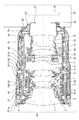
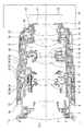
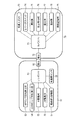
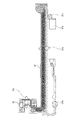
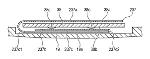
実施例1に係る交換レンズの全長が縮んだ状態(TELE)の断面図である。It is sectional drawing of the state (TELE) in which the total length of the interchangeable lens which concerns on Example 1 is shortened. 実施例1に係る交換レンズの全長が伸長した状態(WIDE)の断面図である。It is sectional drawing of the state (WIDE) in which the total length of the interchangeable lens which concerns on Example 1 is extended. 実施例1の交換レンズとカメラ本体のシステムブロック図である。It is a system block diagram of the interchangeable lens of Example 1 and the camera body. 実施例1に係る交換レンズの一部の分解斜視図である。It is an exploded perspective view of a part of the interchangeable lens which concerns on Example 1. FIG. 実施例1に係るFPCの展開図である。It is a development view of the FPC which concerns on Example 1. FIG. 実施例1に係るFPCの保持状態における拡大斜視図である。It is an enlarged perspective view in the holding state of FPC which concerns on Example 1. FIG. 実施例1に係るFPCの組込状態における断面図である。It is sectional drawing in the built-in state of FPC which concerns on Example 1. FIG. 実施例1に係るFPCの組込状態における部分断面図である。It is a partial cross-sectional view in the built-in state of FPC which concerns on Example 1. FIG. 実施例1に係るFPCの部分断面図である。It is a partial cross-sectional view of FPC which concerns on Example 1. FIG. 実施例2に係るFPCの部分断面図である。It is a partial cross-sectional view of FPC which concerns on Example 2. FIG. 実施例2に係るFPCの主要部の展開図である。It is a development view of the main part of FPC which concerns on Example 2. FIG.

(実施例1)
以下に、本発明の好ましい実施の形態を、添付の図面に基づいて詳細に説明する。なお、図面の一点鎖線で示される光軸方向において、光学素子であるレンズを備えた光学系を有する交換レンズ50(光学装置)の物体側を前側、カメラ本体70にバヨネット固定される固定側を後側と定義する。図1、図2を参照して、本発明の実施例1に係る交換レンズ50について説明する。
(Example 1)
Hereinafter, preferred embodiments of the present invention will be described in detail with reference to the accompanying drawings. In the direction of the optical axis indicated by the alternate long and short dash line in the drawing, the object side of the interchangeable lens 50 (optical device) having an optical system including a lens as an optical element is the front side, and the fixed side fixed to the camera body 70 by a bayonet. Defined as the rear side. The interchangeable lens 50 according to the first embodiment of the present invention will be described with reference to FIGS. 1 and 2.

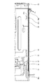
図1は、交換レンズ50の全長が縮んだTELEの状態である交換レンズ50の断面図である。図2は、交換レンズ50の全長が伸長したWIDEの状態である交換レンズ50の断面図である。光学部材である1群レンズ1は、1群鏡筒2により保持される。1群鏡筒2は、1群調整環3により保持され、1群調整環3は光学調整のために1群鏡筒2を光軸方向と光軸方向に垂直な方向における面上で移動させる。1群鏡筒2と1群調整環3は、1群ベース4により保持される。 FIG. 1 is a cross-sectional view of the interchangeable lens 50 in a state of TELE in which the total length of the interchangeable lens 50 is reduced. FIG. 2 is a cross-sectional view of the interchangeable lens 50 in a WIDE state in which the total length of the interchangeable lens 50 is extended. The group 1 lens 1 which is an optical member is held by the group 1 lens barrel 2. The 1st group lens barrel 2 is held by the 1st group adjustment ring 3, and the 1st group adjustment ring 3 moves the 1st group lens barrel 2 on the plane in the direction perpendicular to the optical axis direction and the optical axis direction for optical adjustment. .. The 1st group lens barrel 2 and the 1st group adjustment ring 3 are held by the 1st group base 4.

直進筒5には、被写体側に不図示のフィルタを取り付けるねじ部が形成されている。直進筒5と1群レンズ1は、一体となってズーム作動に伴って進退するが、実施例1ではこれらは互いに不図示の別の支持構造によって支持されて移動する。化粧環6には、交換レンズ50のスペック等が印刷されており、化粧環6は、直進筒5にビス固定されると共に外観を成している。 The straight cylinder 5 is formed with a screw portion for attaching a filter (not shown) on the subject side. The straight cylinder 5 and the group 1 lens 1 move in and out as a unit with the zoom operation, but in the first embodiment, they are supported by different support structures (not shown) and move. The specifications of the interchangeable lens 50 and the like are printed on the decorative ring 6, and the decorative ring 6 is fixed to the straight cylinder 5 with screws and has an appearance.

光学部材である2群レンズ7(フォーカスレンズ)は、2群鏡筒8(フォーカスユニット、可動部材)により保持されており、不図示の直進案内機構によって2群鏡筒8が光軸方向に沿って進退可能に支持される。そして、2群レンズ7と2群鏡筒8は、超音波モータユニット30(超音波モータ)により共に移動され、合焦動作が行われる。この直進案内機構はいわゆるガイドバーと呼ばれる光軸方向に伸びた円筒部材を2本使用しており、2本の内の一方が2群鏡筒8の倒れ/偏芯を決め、他方が光軸を中心とした回転位置を決める。そして、2群鏡筒8がガイドバーに沿って進退できるように支持されている。 The second group lens 7 (focus lens), which is an optical member, is held by the second group lens barrel 8 (focus unit, movable member), and the second group lens barrel 8 is moved along the optical axis direction by a straight-ahead guidance mechanism (not shown). It is supported so that it can move forward and backward. Then, the 2nd group lens 7 and the 2nd group lens barrel 8 are moved together by the ultrasonic motor unit 30 (ultrasonic motor), and the focusing operation is performed. This straight-ahead guidance mechanism uses two cylindrical members extending in the optical axis direction, so-called guide bars, one of which determines the tilt / eccentricity of the second group lens barrel 8 and the other the optical axis. Determine the rotation position around. The second group lens barrel 8 is supported so that it can move forward and backward along the guide bar.

3群レンズ9は、3群鏡筒10により保持されている。光学部材である4群レンズ11は4群鏡筒12により保持されている。4群ユニット40は、光軸方向に対して垂直な面上で4群鏡筒12を移動可能に支持し、4群鏡筒12すなわち4群レンズ11を移動させることで、いわゆる手ブレを補正する光学防振機能を果たす。この光学防振機能を生じさせるためのアクチュエータは、いわゆるボイスコイルモータであるが、その構成の詳細説明は割愛する。 The 3-group lens 9 is held by the 3-group lens barrel 10. The 4-group lens 11, which is an optical member, is held by the 4-group lens barrel 12. The 4-group unit 40 movably supports the 4-group lens barrel 12 on a plane perpendicular to the optical axis direction, and corrects so-called camera shake by moving the 4-group lens barrel 12, that is, the 4-group lens 11. It fulfills the optical anti-vibration function. The actuator for producing this optical vibration isolation function is a so-called voice coil motor, but a detailed description of its configuration is omitted.

5群レンズ13は、5群鏡筒14により保持され、6群レンズ15は、6群鏡筒16により保持されている。そして、5群鏡筒14は、6群鏡筒16に不図示のビスで固定されている。以上で述べた各レンズ群は、それぞれが1つのレンズとして構成されるわけではなく、複数のレンズ群によって構成される場合もあるが、説明の便宜上、その詳細を割愛する。 The 5-group lens 13 is held by the 5-group lens barrel 14, and the 6-group lens 15 is held by the 6-group lens barrel 16. The 5th group lens barrel 14 is fixed to the 6th group lens barrel 16 with a screw (not shown). Each of the lens groups described above is not configured as one lens, but may be composed of a plurality of lens groups, but the details are omitted for convenience of explanation.

光量調節を行う光学部材である絞りユニット17は、4群ユニット40に固定されており、複数の遮光羽根を有する。そして、不図示のステッピングモータを駆動源として絞りユニット17の複数の遮光羽根が駆動され、所望のF値にすることが可能である。前述の3群鏡筒10は、4群ユニット40に一体固定された絞りユニット17と4群鏡筒12に挟まれているが、光軸方向への移動は可能である。 The diaphragm unit 17, which is an optical member for adjusting the amount of light, is fixed to the group 4 unit 40 and has a plurality of light-shielding blades. Then, a plurality of light-shielding blades of the diaphragm unit 17 are driven by a stepping motor (not shown) as a drive source, and a desired F value can be obtained. The above-mentioned 3rd group lens barrel 10 is sandwiched between the aperture unit 17 and the 4th group lens barrel 12 integrally fixed to the 4th group unit 40, but can be moved in the optical axis direction.

所定のフレア光をカットする光学部材である副絞りユニット18は、4群ユニット40に支持されており、絞りユニット17と同様に複数の遮光羽根を内部に有する。そして、不図示のメカ連結機構によって副絞りユニット18の複数の遮光羽根が駆動され、TELE〜WIDEのズーム位置に対応する開口形状に複数の遮光羽根を変化させることが可能である。 The sub-aperture unit 18, which is an optical member that cuts a predetermined flare light, is supported by the fourth group unit 40, and has a plurality of light-shielding blades inside like the aperture unit 17. Then, a plurality of light-shielding blades of the sub-aperture unit 18 are driven by a mechanical connection mechanism (not shown), and it is possible to change the plurality of light-shielding blades into an opening shape corresponding to the zoom positions of TELE to WIDE.

案内筒19(鏡筒部材)が備えられ、この案内筒19の外周側に回転可能に係合するカム環20が更に備えられている。そして、物体側に前側固定筒22、カメラ本体70側に後側固定筒21が備えられ、前側固定筒22は、後側固定筒21の前側にビスで固定されている。更に後側固定筒21には、案内筒19、外観筒24、マウント25、レンズの駆動用IC、マイコン等が配置されたプリント基板23(回路基板)が固定されている。 A guide cylinder 19 (lens barrel member) is provided, and a cam ring 20 rotatably engaged with the outer peripheral side of the guide cylinder 19 is further provided. A front fixing cylinder 22 is provided on the object side, a rear fixing cylinder 21 is provided on the camera body 70 side, and the front fixing cylinder 22 is fixed to the front side of the rear fixing cylinder 21 with screws. Further, a printed circuit board 23 (circuit board) on which a guide cylinder 19, an appearance cylinder 24, a mount 25, a lens driving IC, a microcomputer, and the like are arranged is fixed to the rear fixing cylinder 21.

後側固定筒21にビス固定された外観筒24の外周面には、MF⇔AF切り替えやISモード切り替えをすることができる不図示のスイッチが配置されている。また、後側固定筒21にビス固定されたマウント25には、裏蓋27が固定されており、その内面には有害光をカットする遮光線が配置されている。マウント筒26は、後側固定筒21とマウント25の間に挟まれて固定されており、裏蓋27と同様、その内面には遮光線が配置されている。実施例1の交換レンズ50においては、マウント筒26の光軸方向の厚みを加工等によって変化させることで、撮像部78(撮像素子)への合焦位置が調節可能である。接点ブロック28は、不図示の配線(フレキシブル基板など)によってプリント基板23に接続され、マウント25にビス固定される。 A switch (not shown) capable of switching between MF⇔AF and IS mode is arranged on the outer peripheral surface of the appearance cylinder 24 fixed to the rear fixing cylinder 21 with screws. Further, a back cover 27 is fixed to the mount 25 fixed to the rear fixing cylinder 21 with screws, and a light-shielding line for cutting harmful light is arranged on the inner surface thereof. The mount cylinder 26 is sandwiched and fixed between the rear side fixing cylinder 21 and the mount 25, and like the back cover 27, a light-shielding line is arranged on the inner surface thereof. In the interchangeable lens 50 of the first embodiment, the focusing position on the image pickup unit 78 (image sensor) can be adjusted by changing the thickness of the mount cylinder 26 in the optical axis direction by processing or the like. The contact block 28 is connected to the printed circuit board 23 by a wiring (flexible board or the like) (not shown), and is fixed to the mount 25 with screws.

フォーカス操作環29は、前側固定筒22の径方向の外側に配置され、前側固定筒22を軸として定位置に回転可能に支持されている。フォーカス操作環29を回転させると、その回転を不図示のセンサが検出し、回転量に応じて2群鏡筒8を駆動し、2群レンズ7の合焦制御が行われる。 The focus operation ring 29 is arranged outside the front fixed cylinder 22 in the radial direction, and is rotatably supported at a fixed position about the front fixed cylinder 22 as an axis. When the focus operation ring 29 is rotated, a sensor (not shown) detects the rotation, drives the second group lens barrel 8 according to the amount of rotation, and controls focusing of the second group lens 7.

超音波モータユニット30は、2群鏡筒8の駆動手段であり、圧電素子が発生する超音波振動によって自ら移動することができる。2群鏡筒8と超音波モータユニット30は、不図示の連結機構で係合されており、2群鏡筒8は、超音波モータユニット30と共に移動可能である。 The ultrasonic motor unit 30 is a driving means of the second group lens barrel 8 and can move by itself by the ultrasonic vibration generated by the piezoelectric element. The group 2 lens barrel 8 and the ultrasonic motor unit 30 are engaged by a connecting mechanism (not shown), and the group 2 lens barrel 8 can move together with the ultrasonic motor unit 30.

2群レンズ7の第1のベース31は、前述の直進案内機構を構成するガイドバーの一端を保持する。2群レンズ7の第2のベース32は前述のガイドバーの他端、超音波モータユニット30及び位置検出センサを保持する。すなわち、ガイドバーは、第1のベース31と第2のベース32に挟まれて所定の位置に固定されている。 The first base 31 of the second group lens 7 holds one end of the guide bar constituting the straight-ahead guidance mechanism described above. The second base 32 of the second group lens 7 holds the other end of the guide bar, the ultrasonic motor unit 30, and the position detection sensor. That is, the guide bar is sandwiched between the first base 31 and the second base 32 and fixed at a predetermined position.

ファンクション操作環33は、前側固定筒22を軸として定位置で回転可能に支持されている。フロントカバー34は、ファンクション操作環33が組込まれた後、その押えとして前側固定筒22に固定部材である固定ビス36でビス固定されている。ファンクション操作環33は、フォーカス操作環29と同様に不図示のセンサでその回転量が検出される。実施例1では、この検出された値によって絞りユニット17を制御し、任意のF値に変更することができる。なお、ISO感度やシャッタースピード等、F値とは異なる撮影条件の変更をファンクション操作環33に割り当てることも可能である。 The function operation ring 33 is rotatably supported at a fixed position about the front fixed cylinder 22 as an axis. After the function operation ring 33 is incorporated, the front cover 34 is fixed to the front fixing cylinder 22 with a fixing screw 36 which is a fixing member as a presser. Similar to the focus operation ring 29, the rotation amount of the function operation ring 33 is detected by a sensor (not shown). In the first embodiment, the aperture unit 17 can be controlled by the detected value and changed to an arbitrary F value. It is also possible to assign changes in shooting conditions different from the F value, such as ISO sensitivity and shutter speed, to the function operation ring 33.

フォーカス操作環29の外周面には、固定ビス36を挿入するためのビス通過孔29aが設けられている。実施例1の交換レンズ50においては、固定ビス36をビス締めする際に、既にフォーカス操作環29が組込まれている状態である。そのため、フォーカス操作環29に設けられたビス通過孔29aから固定ビス36を挿入できるようにしている。 A screw passage hole 29a for inserting the fixing screw 36 is provided on the outer peripheral surface of the focus operation ring 29. In the interchangeable lens 50 of the first embodiment, the focus operation ring 29 is already incorporated when the fixing screw 36 is screwed. Therefore, the fixing screw 36 can be inserted through the screw passage hole 29a provided in the focus operation ring 29.

ズーム操作環35は、後側固定筒21に回転自在に支持される。スラスト付勢部材である不図示のウェーブワッシャは、ズーム操作環35と後側固定筒21との間に挟持されることにより、ズーム操作環35を光軸方向へ付勢する、スラスト付勢構造を構成している。不図示のPLカバーワッシャは、ウェーブワッシャとズーム操作環35側の面との間に配置されている。 The zoom operation ring 35 is rotatably supported by the rear fixed cylinder 21. A wave washer (not shown), which is a thrust urging member, has a thrust urging structure that urges the zoom operation ring 35 in the optical axis direction by being sandwiched between the zoom operation ring 35 and the rear fixed cylinder 21. Consists of. The PL cover washer (not shown) is arranged between the wave washer and the surface on the zoom operation ring 35 side.

ズーム操作環35は、金型により樹脂材料で構成されるため、ズーム操作環35の内周面には、金型成型におけるパーティングライン(以降PLと称す。)が存在する。そのPLで発生する微小な段差やバリがウェーブワッシャと接触しないようにPLカバーワッシャが配置されている。カム環20とズーム操作環35は不図示のズームキーによって連結され、ユーザーがズーム操作環35を回転させると、カム環20が回転する構成となっている。ズーム操作環35は後側固定筒21に対して後述する不図示のバヨネット係合によって光軸方向の位置が決められている。 Since the zoom operation ring 35 is made of a resin material by the mold, a parting line (hereinafter referred to as PL) in mold molding exists on the inner peripheral surface of the zoom operation ring 35. The PL cover washer is arranged so that minute steps and burrs generated in the PL do not come into contact with the wave washer. The cam ring 20 and the zoom operation ring 35 are connected by a zoom key (not shown), and when the user rotates the zoom operation ring 35, the cam ring 20 rotates. The position of the zoom operation ring 35 in the optical axis direction is determined by engaging a bayonet (not shown) described later with respect to the rear fixed cylinder 21.

次に、各レンズ群の位置調節機構について説明する。1群鏡筒2と1群調整環3を保持する1群ベース4、3群鏡筒10、2群鏡筒8や超音波モータユニット30を保持する2群レンズ7の第2のベース32には、不図示のコロが各々配置されており、これらのコロがカム環20に係合する。 Next, the position adjustment mechanism of each lens group will be described. On the second base 32 of the 1st group base 4 that holds the 1st group lens barrel 2 and the 1st group adjustment ring 3, the 3rd group lens barrel 10, the 2nd group lens barrel 8 and the 2nd group lens 7 that holds the ultrasonic motor unit 30. Each of the rollers (not shown) is arranged, and these rollers engage with the cam ring 20.

4群ユニット40には、前述のとおり光学防振機能を発揮するためのアクチュエータ及び副絞りユニット18が搭載されているが、更に3群鏡筒10より前側に配置された絞りユニット17も搭載されている。そして、4群ユニット40、5群鏡筒14を保持する6群鏡筒16には、不図示のコロが各々配置されており、これらのコロがカム環20に係合する。 As described above, the 4th group unit 40 is equipped with an actuator and an auxiliary aperture unit 18 for exerting an optical anti-vibration function, but is also equipped with an aperture unit 17 arranged in front of the 3rd group lens barrel 10. ing. Rolls (not shown) are arranged on the 6-group lens barrel 16 that holds the 4-group unit 40 and the 5-group lens barrel 14, and these rollers engage with the cam ring 20.

これらのコロは、それぞれ異なる軌跡を有するカム環20に設けられた不図示のカム溝と係合している。そして、カム溝は、所望のズーム位置において各レンズ群が光学的に所望のレンズ間隔となるような軌跡となっている。カム環20の光軸周りの回転に伴い、1群ベース4、3群鏡筒10、4群ユニット40、6群鏡筒16及び第2のベース32を図1に示す縮んだTELEの位置から図2に示す伸長したWIDEの位置、更にその間の任意のズーム位置に配置することができる。 These rollers are engaged with cam grooves (not shown) provided on the cam ring 20 having different trajectories. The cam groove has a locus such that each lens group optically has a desired lens spacing at a desired zoom position. As the cam ring 20 rotates around the optical axis, the 1st group base 4, the 3rd group lens barrel 10, the 4th group unit 40, the 6th group lens barrel 16 and the 2nd base 32 are moved from the contracted TELE position shown in FIG. It can be arranged at the extended WIDE position shown in FIG. 2 and at any zoom position in between.

カム環20の回転は、不図示のセンサによって検出され、プリント基板23に搭載されたICによってその検出された信号から回転量に応じたズーム位置が判断され、ズーム位置に応じたフォーカス、防振、絞りの制御が行われる。 The rotation of the cam ring 20 is detected by a sensor (not shown), the zoom position according to the amount of rotation is determined from the detected signal by the IC mounted on the printed circuit board 23, and the focus and vibration isolation according to the zoom position are determined. , The aperture is controlled.

実施例1の交換レンズ50は、撮像装置であるカメラ本体70にマウント25で着脱可能にバヨネット固定される。カメラ本体70に交換レンズ50がマウント25で固定されると、各レンズ群の動作を制御する制御手段を備えたプリント基板23は、接点ブロック28を介してカメラ本体70と通信が可能となる。 The interchangeable lens 50 of the first embodiment is detachably fixed to the camera body 70, which is an imaging device, with a mount 25 by a bayonet. When the interchangeable lens 50 is fixed to the camera body 70 by the mount 25, the printed circuit board 23 provided with the control means for controlling the operation of each lens group can communicate with the camera body 70 via the contact block 28.

撮像部78は、カメラ本体70に搭載されており、交換レンズ50を通過した被写体からの光を受光し、その光を電気信号に変換するCMOSやCCD等の光−電気変換素子(撮像素子)である。 The image pickup unit 78 is mounted on the camera body 70, and is an optical-electric conversion element (imaging element) such as CMOS or CCD that receives light from a subject that has passed through the interchangeable lens 50 and converts the light into an electric signal. Is.

図3は、交換レンズ50及びカメラ本体70におけるカメラシステムの電気的構成を示す。まず、カメラ本体70内部の制御フローについて説明する。カメラCPU71はマイクロコンピュータにより構成される。カメラCPU71は、カメラ本体70内の各部の動作を制御する。また、カメラCPU71は、交換レンズ50の装着時にはレンズ側電気接点52、カメラ側電気接点72を介して、交換レンズ50内に設けられたレンズCPU51との通信を行う。カメラCPU71がレンズCPU51に送信する情報(信号)には、2群レンズ7の駆動量情報、平行振れ情報及びピント振れ情報が含まれる。また、レンズCPU51からカメラCPU71に送信する情報(信号)には、撮像倍率情報が含まれる。なお、レンズ側電気接点52、カメラ側電気接点72には、カメラ本体70から交換レンズ50に電源を供給するための接点が含まれている。 FIG. 3 shows the electrical configuration of the camera system in the interchangeable lens 50 and the camera body 70. First, the control flow inside the camera body 70 will be described. The camera CPU 71 is composed of a microcomputer. The camera CPU 71 controls the operation of each part in the camera body 70. Further, when the interchangeable lens 50 is attached, the camera CPU 71 communicates with the lens CPU 51 provided in the interchangeable lens 50 via the lens-side electric contact 52 and the camera-side electric contact 72. The information (signal) transmitted by the camera CPU 71 to the lens CPU 51 includes drive amount information, parallel runout information, and focus runout information of the second group lens 7. Further, the information (signal) transmitted from the lens CPU 51 to the camera CPU 71 includes imaging magnification information. The lens-side electrical contact 52 and the camera-side electrical contact 72 include a contact for supplying power from the camera body 70 to the interchangeable lens 50.

電源スイッチ73は、撮影者により操作可能なスイッチであり、カメラCPU71の起動、及びカメラシステム内の各アクチュエータやセンサ等への電源供給の開始をすることができる。レリーズスイッチ74は、撮影者により操作可能なスイッチであり、第1ストロークスイッチSW1と第2ストロークスイッチSW2とを有する。レリーズスイッチ74からの信号は、カメラCPU71に入力される。カメラCPU71は、第1ストロークスイッチSW1からのON信号の入力に応じて、撮影準備状態に入る。撮影準備状態では、測光部75による被写体輝度の測定と、焦点検出部76による焦点検出が行われる。 The power switch 73 is a switch that can be operated by the photographer, and can start the camera CPU 71 and start supplying power to each actuator, sensor, or the like in the camera system. The release switch 74 is a switch that can be operated by the photographer, and has a first stroke switch SW1 and a second stroke switch SW2. The signal from the release switch 74 is input to the camera CPU 71. The camera CPU 71 enters the shooting preparation state in response to the input of the ON signal from the first stroke switch SW1. In the shooting preparation state, the photometric unit 75 measures the subject brightness and the focus detection unit 76 performs focus detection.

カメラCPU71は、測光部75による測光結果に基づいて絞りユニット17の絞り値や撮像部78の撮像素子の露光量(シャッタ秒時)等を演算する。また、カメラCPU71は、焦点検出部76による撮影光学系の焦点状態の検出結果である焦点情報に基づいて、被写体に対する合焦状態を得るための2群レンズ7及び2群鏡筒8の駆動量(駆動方向を含む)を決定する。なお、焦点情報は、デフォーカス量及びデフォーカス方向である。上記駆動量の情報(2群レンズ7の駆動量情報)は、レンズCPU51に送信される。レンズCPU51は、交換レンズ50の各構成部の動作を制御する。 The camera CPU 71 calculates the aperture value of the aperture unit 17 and the exposure amount (shutter seconds) of the image sensor of the image pickup unit 78 based on the photometric result of the photometric unit 75. Further, the camera CPU 71 drives the 2nd group lens 7 and the 2nd group lens barrel 8 to obtain the focusing state with respect to the subject based on the focus information which is the detection result of the focal state of the photographing optical system by the focus detecting unit 76. Determine (including drive direction). The focus information is the defocus amount and the defocus direction. The drive amount information (drive amount information of the second group lens 7) is transmitted to the lens CPU 51. The lens CPU 51 controls the operation of each component of the interchangeable lens 50.

更にカメラCPU71は、所定の撮影モードになると、4群鏡筒12のシフト駆動、すなわち防振動作の制御を開始する。第2ストロークスイッチSW2からのON信号が入力されると、カメラCPU71は、レンズCPU51に対して絞り駆動命令を送信し、絞りユニット17を先に演算した絞り値に設定する。また、カメラCPU71は、露光部77に露光開始命令を送信し、不図示のミラーの退避動作や不図示のシャッタの開放動作を行わせ、撮像部78の撮像素子において、被写体像の光電変換、すなわち露光動作を行わせる。 Further, the camera CPU 71 starts the shift drive of the 4th group lens barrel 12, that is, the control of the vibration isolation operation when the predetermined shooting mode is set. When the ON signal from the second stroke switch SW2 is input, the camera CPU 71 transmits an aperture drive command to the lens CPU 51, and sets the aperture unit 17 to the previously calculated aperture value. Further, the camera CPU 71 transmits an exposure start command to the exposure unit 77 to perform an operation of retracting a mirror (not shown) and an operation of opening a shutter (not shown), and the image sensor of the image sensor 78 performs photoelectric conversion of the subject image. That is, the exposure operation is performed.

撮像部78からの撮像信号は、カメラCPU71内の信号処理部にてデジタル変換され、更に各種補正処理が施されて画像信号として出力される。画像信号(データ)は、画像記録部79において、フラッシュメモリ等の半導体メモリ、磁気ディスク、光ディスク等の記録媒体に記録保存される。 The image pickup signal from the image pickup unit 78 is digitally converted by the signal processing unit in the camera CPU 71, further subjected to various correction processes, and output as an image signal. The image signal (data) is recorded and stored in the image recording unit 79 in a semiconductor memory such as a flash memory or a recording medium such as a magnetic disk or an optical disk.

次に交換レンズ50内部の制御フローについて説明する。MFリング回転検出部53は、フォーカス操作環29の回転を検出し、ZOOMリング回転検出部54は、ズーム操作環35の回転を検出する。 Next, the control flow inside the interchangeable lens 50 will be described. The MF ring rotation detection unit 53 detects the rotation of the focus operation ring 29, and the ZOOM ring rotation detection unit 54 detects the rotation of the zoom operation ring 35.

IS駆動部55は、防振動作を行う4群鏡筒12の駆動アクチュエータとその駆動回路とを含む。AF駆動部56は、カメラCPU71から送信された2群レンズ7の駆動量情報に応じてAFモータ(超音波モータユニット30)を通じて2群鏡筒8のAF駆動を行う。 The IS drive unit 55 includes a drive actuator of the fourth group lens barrel 12 that performs vibration isolation operation and a drive circuit thereof. The AF drive unit 56 performs AF drive of the second group lens barrel 8 through an AF motor (ultrasonic motor unit 30) according to the drive amount information of the second group lens 7 transmitted from the camera CPU 71.

電磁絞り駆動部57は、カメラCPU71からの絞り駆動命令を受けたレンズCPU51により制御されて、絞りユニット17を指定された絞り値に相当する開口状態に動作させる。 The electromagnetic aperture drive unit 57 is controlled by the lens CPU 51 that receives an aperture drive command from the camera CPU 71 to operate the aperture unit 17 in an open state corresponding to a specified aperture value.

角速度センサ58は、交換レンズ50に搭載され、プリント基板23に接続されている。角速度センサ58は、カメラシステムの角度振れである縦(ピッチ方向)振れと横(ヨー方向)振れのそれぞれの角速度を検出し、検出値を角速度信号としてレンズCPU51に出力する。レンズCPU51は、角速度センサ58からのピッチ方向及びヨー方向の角速度信号を電気的又は機械的に積分して、それぞれの方向での変位量であるピッチ方向振れ量及びヨー方向振れ量(これらをまとめて角度振れ量という。)を演算する。 The angular velocity sensor 58 is mounted on the interchangeable lens 50 and connected to the printed circuit board 23. The angular velocity sensor 58 detects the angular velocities of the vertical (pitch direction) runout and the lateral (yaw direction) runout, which are the angular velocities of the camera system, and outputs the detected values as angular velocity signals to the lens CPU 51. The lens CPU 51 electrically or mechanically integrates the angular velocity signals in the pitch direction and the yaw direction from the angular velocity sensor 58, and the amount of displacement in each direction, the amount of runout in the pitch direction and the amount of runout in the yaw direction (collecting these). Is called the amount of angular velocity.)

レンズCPU51は、上記の角度振れ量と平行振れ量の合成変位量に基づいてIS駆動部55を制御して4群鏡筒12をシフト駆動させ、角度振れ補正及び平行振れ補正を行う。また、レンズCPU51は、ピント振れ量に基づいてAF駆動部56を制御して2群鏡筒8を光軸方向に駆動させ、ピント振れ補正を行う。 The lens CPU 51 controls the IS drive unit 55 based on the combined displacement amount of the above-mentioned angular runout amount and parallel runout amount to shift drive the 4th group lens barrel 12, and performs angle runout correction and parallel runout correction. Further, the lens CPU 51 controls the AF drive unit 56 based on the amount of focus shake to drive the group 2 lens barrel 8 in the optical axis direction to correct the focus shake.

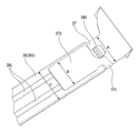
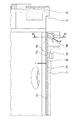
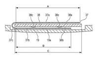
次に、FPC37(フレキシブル基板)とFPC保持板金38(保持部材)の保持構成に関する詳細を説明する。図4はFPC37とFPC保持板金38の保持構成を説明するための交換レンズ50の分解斜視図である。図5は、FPC37の展開図である。図6は、FPC保持板金38にFPC37を保持している状態を示す斜視図である。図7は、FPC37とFPC保持板金38を組込んだ状態の断面図であり、図8は図7の一部を拡大した部分断面図である。また、図9は、図8に示す断面線IX−IXにおける断面図である。 Next, the details regarding the holding configuration of the FPC 37 (flexible substrate) and the FPC holding sheet metal 38 (holding member) will be described. FIG. 4 is an exploded perspective view of the interchangeable lens 50 for explaining the holding configuration of the FPC 37 and the FPC holding sheet metal 38. FIG. 5 is a developed view of the FPC 37. FIG. 6 is a perspective view showing a state in which the FPC 37 is held by the FPC holding sheet metal 38. FIG. 7 is a cross-sectional view of a state in which the FPC 37 and the FPC holding sheet metal 38 are incorporated, and FIG. 8 is a partial cross-sectional view of a part of FIG. 7. Further, FIG. 9 is a cross-sectional view taken along the cross-sectional line IX-IX shown in FIG.

超音波モータユニット30は、不図示の別のFPCによりFPC37を介して、プリント基板23に電気的に接続されている。図5に示すように、FPC37には、位置検出センサ39が実装されており、位置検出センサ39はプリント基板23と電気的に接続されている。そして、FPC37における位置検出センサ39が実装されている部分は、第2のベース32に固定されている。 The ultrasonic motor unit 30 is electrically connected to the printed circuit board 23 via the FPC 37 by another FPC (not shown). As shown in FIG. 5, a position detection sensor 39 is mounted on the FPC 37, and the position detection sensor 39 is electrically connected to the printed circuit board 23. The portion of the FPC 37 on which the position detection sensor 39 is mounted is fixed to the second base 32.

図4に示すように、FPC37はFPC保持板金38により保持される。FPC37とFPC保持板金38の保持構成に関する詳細は後述する。2群鏡筒8の進退の位置は、検出手段である位置検出センサ39によって検出され、位置検出信号が出力される。その位置検出信号に基づいて、2群鏡筒8を所定量移動させるように超音波モータユニット30を駆動制御することで、所望の合焦位置への移動が可能となる。 As shown in FIG. 4, the FPC 37 is held by the FPC holding sheet metal 38. Details regarding the holding configuration of the FPC 37 and the FPC holding sheet metal 38 will be described later. The position of advance / retreat of the group 2 lens barrel 8 is detected by the position detection sensor 39 which is a detection means, and a position detection signal is output. By driving and controlling the ultrasonic motor unit 30 so as to move the group 2 lens barrel 8 by a predetermined amount based on the position detection signal, it is possible to move to a desired focusing position.

FPC保持板金38は、導電性を有する金属製の板金であり、一方の端側にフック部38d、他方の端側に先端ばね部38eが形成されている。更に、図9に示すようにFPC保持板金38には、FPC本体部37aを貼付する第1の面38aと、第1の面38aの反対側の面であって、GNDパターン37b(接続部)が当接する第2の面38bが備えられている。そして、図6に示すように第2の面38bには、FPC保持板金38の長手方向に沿って複数の突起部38cが形成されている。 The FPC holding sheet metal 38 is a conductive metal sheet metal, and has a hook portion 38d formed on one end side and a tip spring portion 38e formed on the other end side. Further, as shown in FIG. 9, the FPC holding sheet metal 38 has a first surface 38a to which the FPC main body portion 37a is attached and a surface opposite to the first surface 38a, and is a GND pattern 37b (connection portion). A second surface 38b with which is provided. Then, as shown in FIG. 6, a plurality of protrusions 38c are formed on the second surface 38b along the longitudinal direction of the FPC holding sheet metal 38.

FPC37は、図5に示すように、紙面裏側が裏面であってベース材側であり、紙面表側が表面である、片面フレキシブル基板であり、FPC37の一方の端部において各信号パターンの導体が一部露出している。モータ駆動信号線37d(駆動信号線、第1の信号線)は、不図示の別のFPCを介して接続される超音波モータユニット30を駆動するための駆動信号を通す配線である。センサ出力信号線37e(検出信号線、第2の信号線)は、位置検出センサ39に接続されており、センサ出力信号を通す配線である。FPC本体部37aには、モータ駆動信号線37dとセンサ出力信号線37eの両方が隣接して設けられている。GNDパターン37bは、プリント基板23に設けられたGND信号線(接地信号線)に接続されており、一方の面(絶縁面)は絶縁体で構成され(絶縁層で覆われ)、他方の面(導電面)は導体で構成されている。すなわち、その他方の面では導体が露出している。FPC中継部37cは、FPC本体部37aとGNDパターン37bをつないでおり、GNDパターン37bは、FPC本体部37aの長手方向と直交する方向にFPC中継部37cを介して備えられている。 As shown in FIG. 5, the FPC37 is a single-sided flexible substrate in which the back side of the paper surface is the back surface and the base material side, and the front side of the paper surface is the front surface, and the conductor of each signal pattern is one at one end of the FPC 37. The part is exposed. The motor drive signal line 37d (drive signal line, first signal line) is a wiring through which a drive signal for driving the ultrasonic motor unit 30 connected via another FPC (not shown) is passed. The sensor output signal line 37e (detection signal line, second signal line) is connected to the position detection sensor 39 and is a wiring through which the sensor output signal is passed. Both the motor drive signal line 37d and the sensor output signal line 37e are provided adjacent to the FPC main body 37a. The GND pattern 37b is connected to a GND signal line (ground signal line) provided on the printed circuit board 23, and one surface (insulating surface) is composed of an insulator (covered with an insulating layer) and the other surface. The (conductive surface) is composed of a conductor. That is, the conductor is exposed on the other side. The FPC relay unit 37c connects the FPC main body unit 37a and the GND pattern 37b, and the GND pattern 37b is provided via the FPC relay unit 37c in a direction orthogonal to the longitudinal direction of the FPC main body unit 37a.

FPC37は、不図示の両面テープもしくは粘着剤などで、FPC本体部37aの表面をFPC保持板金38の第1の面38aに貼りつけることによって保持されている。GNDパターン37bは、FPC中継部37c部を1回折り曲げることにより、FPC本体部37aが貼付されているFPC保持板金38の第1の面38aとは反対側の第2の面38bに当接している。 The FPC 37 is held by sticking the surface of the FPC main body 37a to the first surface 38a of the FPC holding sheet metal 38 with a double-sided tape or an adhesive (not shown). The GND pattern 37b abuts on the second surface 38b on the side opposite to the first surface 38a of the FPC holding sheet metal 38 to which the FPC main body 37a is attached by bending the FPC relay portion 37c once. There is.

図6、図9に示すように、GNDパターン37bの幅Bは、FPC本体部37aの短手方向の幅Aよりも狭くなっている。また、GNDパターン37bの幅Bは、FPC保持板金38の幅Cよりも狭くなっている。このような構成とすることで、例えば、FPC本体部37aに導体が露出したGNDパターン37bを設けた場合に比べて、FPC本体部37aの幅AとFPC保持板金38の幅Cを小さくすることができる。よって、装置が大型化するのを回避し、スペース効率をよくすることができる。なお、図9ではわかりやすいように各部品間に隙間を設けた状態で図示しているが、実際には、FPC本体部37aはFPC保持板金38に前述のように両面テープなどで貼付されており、図示されるような隙間はほぼ存在しない。また、突起部38cとGNDパターン37bの間と、GNDパターン37bと案内筒19の間は、接した状態で隙間は無い。 As shown in FIGS. 6 and 9, the width B of the GND pattern 37b is narrower than the width A of the FPC main body 37a in the lateral direction. Further, the width B of the GND pattern 37b is narrower than the width C of the FPC holding sheet metal 38. With such a configuration, the width A of the FPC main body 37a and the width C of the FPC holding sheet metal 38 can be made smaller than, for example, as compared with the case where the FPC main body 37a is provided with the GND pattern 37b in which the conductor is exposed. Can be done. Therefore, it is possible to avoid the device from becoming large and improve the space efficiency. Although the figure is shown in FIG. 9 with a gap between the parts for easy understanding, the FPC main body 37a is actually attached to the FPC holding sheet metal 38 with double-sided tape or the like as described above. , There are almost no gaps as shown. Further, there is no gap between the protrusion 38c and the GND pattern 37b and between the GND pattern 37b and the guide cylinder 19 in a state of being in contact with each other.

図7〜図9に示すように、FPC保持板金38は、FPC本体部37aが貼付された第1の面38aを交換レンズ50の内径側にして、案内筒19の内周面19aに保持されている。FPC保持板金38の第2の面38bに配置されたGNDパターン37bは、突起部38cと案内筒19の内周面19aの間に挟まれている。FPC保持板金38は、弾性を有する金属製の板金で構成されており、フック部38dと先端ばね部38eは、案内筒19に対してチャージ(付勢)される構成となっている。そして、フック部38dによる付勢力F1と先端ばね部38eによる付勢力F2によって突起部38cが案内筒19の内径側に付勢力Fによって圧接された状態で保持される。よって、GNDパターン37bは、突起部38cと案内筒19の間で圧接した状態で挟持されることとなり、GNDパターン37bと突起部38cを確実に接触させて、導通を確実にすることができる。 As shown in FIGS. 7 to 9, the FPC holding sheet metal 38 is held on the inner peripheral surface 19a of the guide cylinder 19 with the first surface 38a to which the FPC main body 37a is attached as the inner diameter side of the interchangeable lens 50. ing. The GND pattern 37b arranged on the second surface 38b of the FPC holding sheet metal 38 is sandwiched between the protrusion 38c and the inner peripheral surface 19a of the guide cylinder 19. The FPC holding sheet metal 38 is made of an elastic metal sheet metal, and the hook portion 38d and the tip spring portion 38e are charged (biased) with respect to the guide cylinder 19. Then, the protrusion 38c is held in a state of being pressed against the inner diameter side of the guide cylinder 19 by the urging force F1 by the hook portion 38d and the urging force F2 by the tip spring portion 38e. Therefore, the GND pattern 37b is sandwiched between the protrusion 38c and the guide cylinder 19 in a state of being in pressure contact with each other, and the GND pattern 37b and the protrusion 38c can be surely brought into contact with each other to ensure continuity.

モータ駆動信号線37dとセンサ出力信号線37eを有するFPC本体部37aをFPC保持板金38に貼付した構成においては、FPC保持板金38とモータ駆動信号線37dは、FPC37の絶縁層を挟んで静電容量を持つ。また、FPC保持板金38とセンサ出力信号線37eも、FPC37の絶縁層を挟んで静電容量を持つ。そのため、もしFPC保持板金38がグランドに接続されていない場合、超音波モータユニット30を駆動するためにモータ駆動信号線37dに通電を行うと、FPC保持板金38内の電荷が振れて電位差が生じることがある。FPC保持板金38の電位変動により、センサ出力信号線37eの電位も変動して、センサ出力信号にノイズが重畳してしまう。よって、2群鏡筒8の位置制御の精度が悪化して正しく制御できなくなるという懸念がある。 In the configuration in which the FPC main body 37a having the motor drive signal line 37d and the sensor output signal line 37e is attached to the FPC holding sheet metal 38, the FPC holding sheet metal 38 and the motor drive signal line 37d are electrostatically charged with the insulating layer of the FPC 37 interposed therebetween. Has capacity. Further, the FPC holding sheet metal 38 and the sensor output signal line 37e also have a capacitance with the insulating layer of the FPC 37 interposed therebetween. Therefore, if the FPC holding sheet metal 38 is not connected to the ground, when the motor drive signal line 37d is energized to drive the ultrasonic motor unit 30, the electric charge in the FPC holding sheet metal 38 swings and a potential difference occurs. Sometimes. Due to the potential fluctuation of the FPC holding sheet metal 38, the potential of the sensor output signal line 37e also fluctuates, and noise is superimposed on the sensor output signal. Therefore, there is a concern that the accuracy of the position control of the second group lens barrel 8 deteriorates and the control cannot be performed correctly.

実施例1では、FPC保持板金38にGNDパターン37bを圧接して確実に導通させて、FPC37を介して、FPC保持板金38をグランドに接続する構成としている。よって、超音波モータユニット30を駆動するための駆動信号に起因するノイズがセンサ出力信号に重畳することが防止され、2群鏡筒8の位置制御の精度悪化を防ぐことが可能となる。 In the first embodiment, the GND pattern 37b is pressed against the FPC holding sheet metal 38 to ensure conduction, and the FPC holding sheet metal 38 is connected to the ground via the FPC 37. Therefore, it is possible to prevent noise caused by the drive signal for driving the ultrasonic motor unit 30 from being superimposed on the sensor output signal, and to prevent deterioration of the accuracy of position control of the second group lens barrel 8.

FPC保持板金38をグランドに接続する方法としては、別途リード線を用いることや、表面処理を一部剥がした案内筒19にFPC保持板金38をビス締めした上で、案内筒19を別途グランドに接続するなどの手法も考えられる。しかしながら、部品点数や組立工数が増えてしまいコスト増加になってしまう。また、案内筒19が樹脂製などで非導電性の場合は前述の方法は有効ではない。実施例1の構成とすることで、部品点数の増加や組立工数の増加、コスト増加をさせずに、ノイズ対策を行うことができるという優れた効果を奏する。 As a method of connecting the FPC holding sheet metal 38 to the ground, a lead wire may be used separately, or the guide cylinder 19 may be separately grounded after the FPC holding sheet metal 38 is screwed to the guide cylinder 19 whose surface treatment has been partially peeled off. Methods such as connecting are also conceivable. However, the number of parts and the number of assembly steps increase, resulting in an increase in cost. Further, when the guide cylinder 19 is made of resin or the like and is non-conductive, the above method is not effective. The configuration of the first embodiment has an excellent effect that noise countermeasures can be taken without increasing the number of parts, assembling man-hours, and cost.

(実施例2)
図10、図11を用いて、本発明の実施例2について説明する。交換レンズ50の構成としては、実施例1と基本的に同様であるので、同様な構成の部分は、実施例1と同符号を付し、詳細な説明は省略し異なる部分のみ説明する。
(Example 2)
Example 2 of the present invention will be described with reference to FIGS. 10 and 11. Since the configuration of the interchangeable lens 50 is basically the same as that of the first embodiment, the parts having the same configuration are designated by the same reference numerals as those of the first embodiment, and detailed description thereof will be omitted and only the different parts will be described.

実施例2は、実施例1に対して、FPC237をFPC保持板金38に保持する構成が異なる。図10は、実施例2に係るFPC237の断面図である。図11は、FPC237の主要部の展開図である。実施例2のFPC237は、GNDパターン237bがFPC237から離間する方向に延在するFPC中継部237cと、FPC中継部237cの両端に第1のFPC曲げ部237c1と第2のFPC曲げ部237c2を備える構成をしている。そして、FPC237は、不図示の両面テープもしくは粘着剤などで、FPC本体部237aの裏面をFPC保持板金38に貼付した状態で保持されている。つまり、実施例2のFPC237の貼付は、実施例1に対してFPC保持板金38に貼付されるFPC本体部237aの面が表裏逆である。したがって、FPC本体部237aが貼付されるFPC保持板金38の面とは反対側の面に、GNDパターン237bの導体を当接させるためには、第1のFPC曲げ部237c1と第2のFPC曲げ部237c2において、2回折り曲げることが必要である。このように2回折り曲げるために、第1のFPC曲げ部237c1と第2のFPC曲げ部237c2の間隔が長く構成されている。そして、上記のように2回の折り曲げにより、GNDパターン237bの導体が露出している面をFPC保持板金38に当接させることができる。実施例1と同様に、GNDパターン237bの幅は、FPC本体部237aの幅よりも狭くしている。また、GNDパターン237bの幅も、FPC保持板金38の幅よりも狭くしている。 The second embodiment is different from the first embodiment in that the FPC 237 is held by the FPC holding sheet metal 38. FIG. 10 is a cross-sectional view of the FPC 237 according to the second embodiment. FIG. 11 is a development view of a main part of FPC237. The FPC 237 of the second embodiment includes an FPC relay portion 237c in which the GND pattern 237b extends in a direction away from the FPC 237, and a first FPC bending portion 237c1 and a second FPC bending portion 237c2 at both ends of the FPC relay portion 237c. It is configured. The FPC 237 is held in a state where the back surface of the FPC main body 237a is attached to the FPC holding sheet metal 38 with a double-sided tape or an adhesive (not shown). That is, in the attachment of the FPC 237 of the second embodiment, the surfaces of the FPC main body portion 237a attached to the FPC holding sheet metal 38 are upside down with respect to the first embodiment. Therefore, in order to bring the conductor of the GND pattern 237b into contact with the surface of the FPC holding sheet metal 38 to which the FPC main body portion 237a is attached, the first FPC bending portion 237c1 and the second FPC bending It is necessary to bend the portion 237c2 twice. In order to bend twice in this way, the distance between the first FPC bending portion 237c1 and the second FPC bending portion 237c2 is long. Then, by bending twice as described above, the surface where the conductor of the GND pattern 237b is exposed can be brought into contact with the FPC holding sheet metal 38. Similar to the first embodiment, the width of the GND pattern 237b is narrower than the width of the FPC main body 237a. Further, the width of the GND pattern 237b is also narrower than the width of the FPC holding sheet metal 38.

なお、図10ではわかりやすいように各部品間に隙間を設けた状態で図示しているが、実際には、FPC本体部237aはFPC保持板金38に両面テープなどで貼付されており、図示されるような隙間はほぼ存在しない。また、突起部38cとGNDパターン237bの間と、第1のFPC曲げ部237c1及び第2のFPC曲げ部237c2と案内筒19の間は、接した状態で隙間は無い。 Although the figure is shown in FIG. 10 with a gap provided between the parts for easy understanding, the FPC main body 237a is actually attached to the FPC holding sheet metal 38 with double-sided tape or the like, and is shown. There is almost no such gap. Further, there is no gap between the protrusion 38c and the GND pattern 237b and between the first FPC bending portion 237c1 and the second FPC bending portion 237c2 and the guide cylinder 19 in a state of contact.

FPC保持板金38は、実施例1と同様に、FPC本体部237aが貼付された面を内径側にして、案内筒19の内周面19aに圧接されて保持されている。突起部38cと案内筒19の間で挟持されるGNDパターン237bも実施例1と同様に、突起部38cと案内筒19の間の内周面19aで圧接した状態で挟持されることとなる。よって、GNDパターン237bと突起部38cを確実に接触させて、導通を確実にすることができる。 Similar to the first embodiment, the FPC holding sheet metal 38 is held by being pressed against the inner peripheral surface 19a of the guide cylinder 19 with the surface to which the FPC main body 237a is attached on the inner diameter side. The GND pattern 237b sandwiched between the protrusion 38c and the guide cylinder 19 is also sandwiched in a state of being pressed against the inner peripheral surface 19a between the protrusion 38c and the guide cylinder 19 as in the first embodiment. Therefore, the GND pattern 237b and the protrusion 38c can be reliably brought into contact with each other to ensure continuity.

実施例2の構成とすることで、実施例1に対して、FPC保持板金38へ貼付されるFPC本体部237aの面が表裏逆であっても、実施例1と同様にノイズ重畳に対して効果を得ることができる。以上、本発明の好ましい実施形態について説明したが、本発明はこれらの実施形態に限定されず、その要旨の範囲内で種々の変形及び変更が可能である。 By adopting the configuration of the second embodiment, even if the surfaces of the FPC main body 237a attached to the FPC holding sheet metal 38 are upside down with respect to the first embodiment, noise superposition is caused as in the first embodiment. The effect can be obtained. Although the preferred embodiments of the present invention have been described above, the present invention is not limited to these embodiments, and various modifications and modifications can be made within the scope of the gist thereof.

19 案内筒(鏡筒部材)
19a 内周面
23 プリント基板(回路基板)
37 FPC(フレキシブル基板)
37a FPC本体部(本体部)
37b GNDパターン(接続部)
37c FPC中継部(中継部)
38 FPC保持板金(保持部材)
38a 第1の面
38b 第2の面
50 交換レンズ(光学装置)
19 Guide tube (lens barrel member)
19a Inner peripheral surface 23 Printed circuit board (circuit board)
37 FPC (Flexible Substrate)
37a FPC main body (main body)
37b GND pattern (connection part)
37c FPC relay section (relay section)
38 FPC holding sheet metal (holding member)
38a First surface 38b Second surface 50 Interchangeable lens (optical device)

Claims (15)

フレキシブル基板と、
該フレキシブル基板を保持する導電性の保持部材と、
内周面により前記保持部材を保持する鏡筒部材と、
前記フレキシブル基板が接続される回路基板とを有し、
前記フレキシブル基板は、前記保持部材の第1の面により保持される本体部と、前記回路基板の接地信号線に接続される接続部と、前記本体部と前記接続部とをつなぐ中継部とを含み、
前記接続部は、前記保持部材の第2の面と前記鏡筒部材とにより挟持されることを特徴とする光学装置。
Flexible board and
A conductive holding member for holding the flexible substrate and
A lens barrel member that holds the holding member by the inner peripheral surface, and
It has a circuit board to which the flexible board is connected.
The flexible substrate comprises a main body portion held by the first surface of the holding member, a connection portion connected to the ground signal line of the circuit board, and a relay portion connecting the main body portion and the connection portion. Including
The optical device is characterized in that the connecting portion is sandwiched between the second surface of the holding member and the lens barrel member.
前記接続部は、前記中継部が1回折り曲げられた状態で前記第2の面に当接することを特徴とする請求項1に記載の光学装置。 The optical device according to claim 1, wherein the connecting portion abuts on the second surface in a state where the relay portion is bent once. 前記接続部は、前記中継部が2回折り曲げられた状態で前記第2の面に当接することを特徴とする請求項1に記載の光学装置。 The optical device according to claim 1, wherein the connecting portion abuts on the second surface in a state where the relay portion is bent twice. 前記接続部は、前記第2の面に当接する導電面を含むことを特徴とする請求項1乃至3の何れか一項に記載の光学装置。 The optical device according to any one of claims 1 to 3, wherein the connecting portion includes a conductive surface that abuts on the second surface. 前記接続部は、前記導電面とは反対側に設けられた絶縁面を含むことを特徴とする請求項4に記載の光学装置。 The optical device according to claim 4, wherein the connecting portion includes an insulating surface provided on a side opposite to the conductive surface. 前記保持部材は弾性を有し、前記接続部は前記弾性による付勢力により前記鏡筒部材に圧接されることを特徴とする請求項1乃至5の何れか一項に記載の光学装置。 The optical device according to any one of claims 1 to 5, wherein the holding member has elasticity, and the connecting portion is pressed against the lens barrel member by an urging force due to the elasticity. 前記接続部の幅は、前記本体部の幅よりも狭いことを特徴とする請求項1乃至6の何れか一項に記載の光学装置。 The optical device according to any one of claims 1 to 6, wherein the width of the connecting portion is narrower than the width of the main body portion. 前記接続部の幅は、前記保持部材の幅よりも狭いことを特徴とする請求項1乃至7の何れか一項に記載の光学装置。 The optical device according to any one of claims 1 to 7, wherein the width of the connecting portion is narrower than the width of the holding member. 前記接続部は、前記本体部の長手方向と直交する方向に前記中継部を介して備えられていることを特徴とする請求項1乃至8の何れか一項に記載の光学装置。 The optical device according to any one of claims 1 to 8, wherein the connecting portion is provided via the relay portion in a direction orthogonal to the longitudinal direction of the main body portion. 前記中継部は、接地信号線を含むことを特徴とする請求項1乃至9の何れか一項に記載の光学装置。 The optical device according to any one of claims 1 to 9, wherein the relay unit includes a ground signal line. 前記第2の面は突起部を含み、前記接続部は前記突起部に当接することを特徴とする請求項1乃至10の何れか一項に記載の光学装置。 The optical device according to any one of claims 1 to 10, wherein the second surface includes a protrusion, and the connection portion abuts on the protrusion. 光学部材と、
該光学部材を移動させる駆動手段と、
前記光学部材の位置を検出する検出手段と、を有し、
前記本体部は、前記駆動手段に接続する第1の信号線と前記検出手段に接続する第2の信号線とを備えることを特徴とする請求項1乃至11の何れか一項に記載の光学装置。
Optical members and
A driving means for moving the optical member and
It has a detecting means for detecting the position of the optical member, and has
The optics according to any one of claims 1 to 11, wherein the main body includes a first signal line connected to the driving means and a second signal line connected to the detecting means. apparatus.
前記回路基板は、前記駆動手段を制御する制御手段を備えることを特徴とする請求項12に記載の光学装置。 The optical device according to claim 12, wherein the circuit board includes a control means for controlling the drive means. 前記駆動手段は、超音波振動によって駆動する超音波モータであることを特徴とする請求項12又は13に記載の光学装置。 The optical device according to claim 12 or 13, wherein the driving means is an ultrasonic motor driven by ultrasonic vibration. 請求項1乃至14の何れか一項に記載の光学装置を有することを特徴とする撮像装置。 An imaging device comprising the optical device according to any one of claims 1 to 14.
JP2019157718A 2019-08-30 2019-08-30 Optical device and imaging device Active JP7328831B2 (en)

Priority Applications (1)

Application Number Priority Date Filing Date Title
JP2019157718A JP7328831B2 (en) 2019-08-30 2019-08-30 Optical device and imaging device

Applications Claiming Priority (1)

Application Number Priority Date Filing Date Title
JP2019157718A JP7328831B2 (en) 2019-08-30 2019-08-30 Optical device and imaging device

Publications (3)

Publication Number Publication Date
JP2021036282A true JP2021036282A (en) 2021-03-04
JP2021036282A5 JP2021036282A5 (en) 2022-09-02
JP7328831B2 JP7328831B2 (en) 2023-08-17

Family

ID=74716524

Family Applications (1)

Application Number Title Priority Date Filing Date
JP2019157718A Active JP7328831B2 (en) 2019-08-30 2019-08-30 Optical device and imaging device

Country Status (1)

Country Link
JP (1) JP7328831B2 (en)

Cited By (1)

* Cited by examiner, † Cited by third party
Publication number Priority date Publication date Assignee Title
JP2023155632A (en) * 2022-04-11 2023-10-23 キヤノン株式会社 Connection members, lens barrels and optical equipment

Citations (5)

* Cited by examiner, † Cited by third party
Publication number Priority date Publication date Assignee Title
JP2005003766A (en) * 2003-06-10 2005-01-06 Nikon Corp Lens barrel
JP2011158725A (en) * 2010-02-01 2011-08-18 Nikon Corp Lens barrel and optical device
JP2013172245A (en) * 2012-02-20 2013-09-02 Sony Corp Camera device, electronic apparatus, and flexible chassis
WO2015016002A1 (en) * 2013-08-01 2015-02-05 富士フイルム株式会社 Imaging module and electronic apparatus
JP2017106950A (en) * 2015-12-07 2017-06-15 キヤノン株式会社 Lens barrel and optical instrument

Patent Citations (5)

* Cited by examiner, † Cited by third party
Publication number Priority date Publication date Assignee Title
JP2005003766A (en) * 2003-06-10 2005-01-06 Nikon Corp Lens barrel
JP2011158725A (en) * 2010-02-01 2011-08-18 Nikon Corp Lens barrel and optical device
JP2013172245A (en) * 2012-02-20 2013-09-02 Sony Corp Camera device, electronic apparatus, and flexible chassis
WO2015016002A1 (en) * 2013-08-01 2015-02-05 富士フイルム株式会社 Imaging module and electronic apparatus
JP2017106950A (en) * 2015-12-07 2017-06-15 キヤノン株式会社 Lens barrel and optical instrument

Cited By (1)

* Cited by examiner, † Cited by third party
Publication number Priority date Publication date Assignee Title
JP2023155632A (en) * 2022-04-11 2023-10-23 キヤノン株式会社 Connection members, lens barrels and optical equipment

Also Published As

Publication number Publication date
JP7328831B2 (en) 2023-08-17

Similar Documents

Publication Publication Date Title
CN111665608B (en) Lens barrel and image pickup apparatus
JP2024026838A (en) Optical device and imaging apparatus
JP2007233214A (en) Vibration correction device, lens barrel, and optical device
EP3267238A1 (en) Lens barrel
JPH10253869A (en) Optical element position correction device, focusing device, and optical device
US12007682B2 (en) Image stabilization apparatus, lens apparatus, and camera
JP4750565B2 (en) Vibration correction apparatus and optical apparatus
JP2014191164A (en) Lens barrel, interchangeable lens, and photographing apparatus
US11974043B2 (en) Image stabilization unit, lens apparatus, and image pickup apparatus
JP2006201252A (en) Imaging apparatus
JP7328831B2 (en) Optical device and imaging device
US20250102888A1 (en) Optical apparatus
US11662545B2 (en) Optical apparatus and image pickup apparatus using the same
US12149823B2 (en) Optical apparatus and camera system
JP7566644B2 (en) Lens device, imaging device, and imaging system
JP4871679B2 (en) Image blur correction device, lens barrel, and imaging device
JP4774859B2 (en) Retractable zoom lens barrel
US7050243B2 (en) Lens apparatus, camera system, and camera
JP2017106950A (en) Lens barrel and optical instrument
JP7467050B2 (en) Optical device and imaging device
JP7663376B2 (en) Optical device and imaging device
JP7706909B2 (en) optical equipment
JP3795484B2 (en) Lens barrel, barrel unit and camera
JPH07159668A (en) Lens barrel
JP2021036277A (en) Optical equipment and imaging equipment

Legal Events

Date Code Title Description
RD01 Notification of change of attorney

Free format text: JAPANESE INTERMEDIATE CODE: A7421

Effective date: 20220630

A521 Request for written amendment filed

Free format text: JAPANESE INTERMEDIATE CODE: A523

Effective date: 20220825

A621 Written request for application examination

Free format text: JAPANESE INTERMEDIATE CODE: A621

Effective date: 20220825

A977 Report on retrieval

Free format text: JAPANESE INTERMEDIATE CODE: A971007

Effective date: 20230623

TRDD Decision of grant or rejection written
A01 Written decision to grant a patent or to grant a registration (utility model)

Free format text: JAPANESE INTERMEDIATE CODE: A01

Effective date: 20230706

A61 First payment of annual fees (during grant procedure)

Free format text: JAPANESE INTERMEDIATE CODE: A61

Effective date: 20230804

R151 Written notification of patent or utility model registration

Ref document number: 7328831

Country of ref document: JP

Free format text: JAPANESE INTERMEDIATE CODE: R151