JP2021029596A - Knee joint assist device - Google Patents
Knee joint assist device Download PDFInfo
- Publication number
- JP2021029596A JP2021029596A JP2019152891A JP2019152891A JP2021029596A JP 2021029596 A JP2021029596 A JP 2021029596A JP 2019152891 A JP2019152891 A JP 2019152891A JP 2019152891 A JP2019152891 A JP 2019152891A JP 2021029596 A JP2021029596 A JP 2021029596A
- Authority
- JP
- Japan
- Prior art keywords
- gear
- knee joint
- fixed
- arm member
- main body
- Prior art date
- Legal status (The legal status is an assumption and is not a legal conclusion. Google has not performed a legal analysis and makes no representation as to the accuracy of the status listed.)
- Granted
Links
- 210000000629 knee joint Anatomy 0.000 title claims abstract description 55
- 210000000689 upper leg Anatomy 0.000 claims abstract description 15
- 210000001699 lower leg Anatomy 0.000 claims description 13
- 210000002414 leg Anatomy 0.000 claims description 6
- 230000033001 locomotion Effects 0.000 abstract description 35
- 210000003127 knee Anatomy 0.000 description 9
- 238000005096 rolling process Methods 0.000 description 5
- 238000010586 diagram Methods 0.000 description 4
- 230000007246 mechanism Effects 0.000 description 3
- 238000005452 bending Methods 0.000 description 2
- 230000005540 biological transmission Effects 0.000 description 2
- 229920001971 elastomer Polymers 0.000 description 2
- 239000000806 elastomer Substances 0.000 description 2
- 239000004744 fabric Substances 0.000 description 2
- 239000010985 leather Substances 0.000 description 2
- 238000005259 measurement Methods 0.000 description 2
- 239000004033 plastic Substances 0.000 description 2
- 210000002303 tibia Anatomy 0.000 description 2
- 238000006073 displacement reaction Methods 0.000 description 1
- 238000011156 evaluation Methods 0.000 description 1
- 230000000474 nursing effect Effects 0.000 description 1
- 230000002093 peripheral effect Effects 0.000 description 1
- 238000004088 simulation Methods 0.000 description 1
Images


Abstract
Description
本発明は、ヒトの歩行や膝屈伸運動を補助する膝関節補助装置に関する。 The present invention relates to a knee joint assisting device that assists human walking and knee flexion / extension movements.
膝関節補助装置は、装着者の日常の或いはリハビリ時の歩行や屈伸運動を補助するために、様々なものが開発されている。例えば、特許文献1には、支持軸を中心として相対的に回転自在に支持された上部アームと下部アームを装着者の大腿部と下腿部に取り付け、上部アームの所定角度位置を超える旋回動を阻止するためのストッパーを下部アームに設けた膝装着具が記載されている。特許文献1の膝装着具は、膝関節のすべり転がり運動またはロールバック運動(例えば、非特許文献2参照)に追従することができず、歩行運動または屈伸運動を妨げてしまう。 Various knee joint assist devices have been developed to assist the wearer in walking and bending / stretching exercises during daily or rehabilitation. For example, in Patent Document 1, an upper arm and a lower arm that are relatively rotatably supported around a support shaft are attached to the thigh and lower leg of the wearer, and the upper arm is swiveled beyond a predetermined angle position. A knee wearer with a stopper on the lower arm to prevent movement is described. The knee fitting of Patent Document 1 cannot follow the sliding or rolling motion or rollback motion of the knee joint (see, for example, Non-Patent Document 2), and hinders the walking motion or the bending and stretching motion.
この点、特許文献2には、下腿装着部の膝関節側端部が前後方向にスライド可能として、膝関節のすべり転がり運動に適合した膝関節運動補助装置が記載されている。然しながら、特許文献2の膝関節運動補助装置では、動力源としてのモーター、平歯車およびすぐばかさ歯車を含む動力伝達装置およびバッテリを備えており、装置が重量とならざるを得ず、リハビリテーション支援、介助作業支援、看護作業支援、農作業支援等の様々な用途に応用すること、特に重度の障害者へ適用することが困難である問題がある。
In this regard,
非特許文献1には、電磁モータ、非円形歯車および溝カムを用いた歩行リハビリ用の膝関節アシスト装具が開示されている。非特許文献1の膝関節アシスト装具も膝関節のすべり転がり運動またはロールバック運動に適合しているが、電磁モータやバッテリ等の重量物を搭載しており、装具自体が重く、特許文献2の場合と同様に、様々な用途に応用すること、特に重度の障害者へ適用することが困難である問題がある。 Non-Patent Document 1 discloses a knee joint assist orthosis for walking rehabilitation using an electromagnetic motor, a non-circular gear, and a groove cam. The knee joint assist orthosis of Non-Patent Document 1 is also suitable for the sliding or rolling motion of the knee joint, but it is equipped with a heavy object such as an electromagnetic motor or a battery, and the orthosis itself is heavy. As in the case, there is a problem that it is difficult to apply it to various uses, especially to a person with severe disability.
本発明は、こうした従来技術の問題を解決することを技術課題としており、膝関節のロールバック運動により良く適合しながら、軽量で種々の用途に適用可能な膝関節補助装置を提供することを目的としている。 An object of the present invention is to solve the problems of the prior art, and to provide a lightweight knee joint assisting device that can be applied to various applications while better adapting to the rollback movement of the knee joint. It is said.
本発明によれば、本体と、直線に沿って延びる直線歯車部分および前記直線に接する円弧に沿って延びるセクタ歯車部分とを有し、前記本体内に配設された固定歯車と、前記本体内に配設され、前記固定歯車に係合する移動歯車と、記移動歯車に取り付けられ、前記固定歯車に沿って前記移動歯車と共に移動する第1の腕部材と、前記本体に固定された第2の腕部材とを具備し、前記第1の腕部材を装着者の大腿部に固定し、前記第2の腕部材を前記装着者の下腿部に固定するようにした膝関節補助装置が提供される。 According to the present invention, a fixed gear having a main body, a linear gear portion extending along a straight line, and a sector gear portion extending along an arc in contact with the straight line, and a fixed gear arranged in the main body, and the inside of the main body. A moving gear that is disposed in and engages with the fixed gear, a first arm member that is attached to the moving gear and moves with the moving gear along the fixed gear, and a second arm member fixed to the main body. The knee joint assisting device is provided with the above-mentioned arm member, the first arm member is fixed to the wearer's thigh, and the second arm member is fixed to the wearer's lower leg. Provided.
本発明は、ヒトの膝関節のロールバック動作に非常に近い運動を再現することが可能でありながら、構造が簡単で軽量であるために、非常に多種多様な用途に適用することができる。 The present invention can be applied to a wide variety of applications due to its simple structure and light weight, while being able to reproduce a motion very similar to the rollback motion of a human knee joint.
以下、添付図面を参照して、本発明の好ましい実施形態を説明する。
図1において、本実施形態による膝関節補助装置10は、平行に配置された2枚の板状部材より成る本体部12、14と、該本体部12、14の間に固定された固定歯車24と、該固定歯車24に係合する移動歯車20と、本体部12、14の間に配置された付勢手段としてのねじりコイルばねまたはトーションばね32と、移動歯車20の回転軸22に取り付けられた第1の腕部材16と、本体部12、14に固定された第2の腕部材18を主要な構成要素として備えている。本体部12、14には案内溝12a、14aが形成されている。
Hereinafter, preferred embodiments of the present invention will be described with reference to the accompanying drawings.
In FIG. 1, the knee
膝関節補助装置10は、図2に示すように、第1の腕部材16に取り付けられた上腿部装着具40と、第2の腕部材18に取り付けられた下腿部装着具42とを有している。上腿部装着具40は、ヒトの大腿部の表面に馴染むエラストマー、プラスチック、革、布帛等により形成することができ、該上腿部装着具40をヒトの大腿部の外側の側面に固定するバンド40aを有している。下腿部装着具42は、ヒトの下腿部の表面に馴染むエラストマー、プラスチック、革、布帛等により形成することができ、該下腿部装着具42をヒトの下腿部の外側の側面に固定するバンド42aを有している。
As shown in FIG. 2, the knee
膝関節補助装置10は、移動歯車20の回転軸22が、起立姿勢の装着者の膝関節の回転軸線に概ね一致するように、装着者の膝関節の外側の側面に装着される。このとき、第1の腕部材16が上方に突出し、第2の腕部材18が下方に突出し、好ましくは、第1と第2の腕部材16、18は一直線上に配置される。膝関節補助装置10の本体部12、14それ自体は、装着者の膝関節に固定されることはない。
The knee
固定歯車24は矩形の板状の部材より成る本体部分24aを有している。本体部分24aは、該本体部分24aの一方の測縁部から膨出した扇状部分24bを有している。固定歯車24は、本体部分24aの上縁部に沿って歯切りされた直線歯車部分26と、直線歯車部分26の一端から接線方向に接続するように、扇状部分24bの外周面に沿って歯切りされたセクタ歯車部分28とを有している。より詳細には、直線歯車部分26とセクタ歯車部分28は、直線歯車部分26のピッチ線がセクタ歯車部分28のピッチ円に接するように配置されている。なお、膝関節補助装置10を起立姿勢の使用者の膝関節の外側側面に装着したとき、直線歯車部分26のピッチ線は概ね水平方向に延びる。また、セクタ歯車部分28は、膝関節補助装置10を使用者の膝関節に取り付けたときに、使用者の後方を向くように配置されている。
The
本体部12、14を形成する板部材の各々に形成された案内溝12a、14aは、少なくとも固定歯車24のセクタ歯車部分28のピッチ円の中心Osに関する円周に沿って形成された円弧部分12b、14bと、円弧部分12b、14bの上側の端部から固定歯車24の直線歯車部分26のピッチ線に平行に伸びる直線部分12c、14cとを有している。
The guide grooves 12a and 14a formed in each of the plate members forming the
移動歯車20は、固定歯車24の直線歯車部分26およびセクタ歯車部分28の歯に係合する歯を有している。移動歯車20は通常の平歯車のような円形の歯車とすることができるが、固定歯車24の直線歯車部分26に係合する部分と、セクタ歯車部分28に係合する部分とで異なる半径としてもよい。移動歯車20は、本体部12、14を形成する板部材に対して垂直に延びる回転軸22を中心として回転する。移動歯車20は、回転軸22と共に、或いは、回転軸22に対して相対的に回転可能となっている。回転軸22の両端には、案内溝12a、14aに係合するローラまたはフォロア22aを取り付けることができる。こうして、移動歯車20は、回転軸22を中心として回転しつつ、案内溝12a、14aに沿って移動可能となる。
The
トーションばね32は、本体部12、14の内面に固定されたトーションばね取付部としてのボス部30に取り付けられる。トーションばね32は、第1と第2の脚部32a、32bを有している。トーションばね32をボス部30に取り付けたとき、第1の脚部32aは、移動歯車20の回転軸22または回転軸22に取り付けられているローラまたはフォロア22aに係合する。第2の脚部32bは、第2の腕部材18の近傍に配置されたトーションばね係留部34に固定される。
The
第1の腕部材16は、図3に示すように、第1の腕部材16の中心軸線Omが第2の腕部材18の中心軸線Oに概ね一直線上に配置される位置(0°の位置)から、中心軸線Omが中心軸線Oに対して90°の角度をなす位置(図4)を経て、中心軸線Omが中心軸線Oに対して150°の角度をなす位置(図5)まで、本体部12、14に対して移動することができる。
As shown in FIG. 3, the
この間、トーションばね32は、0°の位置へ復帰する方向に移動歯車20の回転軸22を付勢する。トーションばね32から回転軸22への付勢力は、角度が大きくなにつれ次第に大きくなる。つまり、トーションばね32から回転軸22への付勢力は、膝関節補助装置10を装着した装着者が最も深く屈曲させたときに最も大きくなり、そうした姿勢から膝を伸ばす際に、装着者の膝伸展動作を良好に補助することが可能となる。
During this time, the
図6は、白石善孝等が行った、膝関節のX線動画像により装着者(被験者)がスクワットを行ったときの膝関節の動作の分析結果に基づき、膝中心の移動を直線近似して作成した膝関節運動モデルを示している。膝の屈伸運動は、ロールバック運動(Rollback Motion)とも称される、脛骨上の大腿骨の転がり運動と滑り運動による複合運動であり、完全伸展位から屈曲初期には、大腿骨が脛骨に対して回転する転がり運動のみであるが、徐々に滑り運動が加わり、最終的には滑り運動のみとなる。 FIG. 6 shows a linear approximation of the movement of the center of the knee based on the analysis result of the movement of the knee joint when the wearer (subject) squats by the X-ray image of the knee joint performed by Yoshitaka Shiraishi and others. The created knee joint movement model is shown. Knee flexion / extension movement, also called rollback motion, is a combined movement of rolling and sliding movements of the femur on the tibia, and the femur is in contact with the tibia from the fully extended position to the initial stage of flexion. It is only a rolling motion that rotates, but a sliding motion is gradually added, and finally it becomes only a sliding motion.
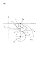
本実施形態では、移動歯車20の回転軸22が、なるべく図6のモデルに沿って移動できるように膝関節補助装置10の寸法を決定した。図7を参照すると、膝関節補助装置10の運動モデルが示されている。図7において、回転軸22の移動は一点鎖線で示されている。また、図7では、X軸は前後方向(左方が装着者の前方)であり、Z軸は上下方向である。
In the present embodiment, the dimensions of the knee joint assisting
r1は移動歯車20において固定歯車24の直線歯車部分26(図7では2)に係合する部分1の半径であり、r2はセクタ歯車部分28(図7では4)に係合する部分3の半径であり、r3はセクタ歯車部分4の半径である。θ1は、移動歯車20の回転軸22の中心Omgに関する部分1の中心角度であり、θ2は、移動歯車20の回転軸22の中心Omgに関する部分2の中心角度である。
r1 is the radius of the portion 1 of the moving
r1=r2=12mm、r3=8mm、θ1=30°、θ2=120として、実際に膝関節補助装置10を作製し、回転軸22の動作を測定した。測定結果を図6において一点鎖線で示す。図6から理解されるように、本実施形態による膝関節補助装置10は、実線で示すヒトの膝関節のロールバック動作に非常に近い運動を再現することが可能である。
The knee joint assisting
10 膝関節補助装置
12 本体部
12a 案内溝
12b 円弧部分
12c 直線部分
14 本体部
14a 案内溝
14b 円弧部分
14c 直線部分
16 第1の腕部材
18 第2の腕部材
20 移動歯車
22 回転軸
22a フォロア
24 固定歯車
24a 本体部分
24b 扇状部分
26 直線歯車部分
28 セクタ歯車部分
30 ボス部
32a 第1の脚部
32b 第2の脚部
34 係留部
40 上腿部装着具
40a バンド
42 下腿部装着具
42a バンド
10 Knee
Claims (5)
直線に沿って延びる直線歯車部分および前記直線に接する円弧に沿って延びるセクタ歯車部分とを有し、前記本体内に配設された固定歯車と、
前記本体内に配設され、前記固定歯車に係合する移動歯車と、
前記移動歯車に取り付けられ、前記固定歯車に沿って前記移動歯車と共に移動する第1の腕部材と、
前記本体に固定された第2の腕部材とを具備し、
前記第1の腕部材を装着者の大腿部に固定し、前記第2の腕部材を前記装着者の下腿部に固定するようにした膝関節補助装置。 With the main body
A fixed gear having a linear gear portion extending along a straight line and a sector gear portion extending along an arc in contact with the straight line, and a fixed gear arranged in the main body.
A moving gear disposed in the main body and engaged with the fixed gear,
A first arm member attached to the moving gear and moving along with the moving gear along the fixed gear.
A second arm member fixed to the main body is provided.
A knee joint assisting device in which the first arm member is fixed to the thigh of the wearer and the second arm member is fixed to the lower leg of the wearer.
Priority Applications (1)
| Application Number | Priority Date | Filing Date | Title |
|---|---|---|---|
| JP2019152891A JP7300168B2 (en) | 2019-08-23 | 2019-08-23 | knee joint assist device |
Applications Claiming Priority (1)
| Application Number | Priority Date | Filing Date | Title |
|---|---|---|---|
| JP2019152891A JP7300168B2 (en) | 2019-08-23 | 2019-08-23 | knee joint assist device |
Publications (2)
| Publication Number | Publication Date |
|---|---|
| JP2021029596A true JP2021029596A (en) | 2021-03-01 |
| JP7300168B2 JP7300168B2 (en) | 2023-06-29 |
Family
ID=74677946
Family Applications (1)
| Application Number | Title | Priority Date | Filing Date |
|---|---|---|---|
| JP2019152891A Active JP7300168B2 (en) | 2019-08-23 | 2019-08-23 | knee joint assist device |
Country Status (1)
| Country | Link |
|---|---|
| JP (1) | JP7300168B2 (en) |
Cited By (2)
| Publication number | Priority date | Publication date | Assignee | Title |
|---|---|---|---|---|
| WO2023070466A1 (en) * | 2021-10-28 | 2023-05-04 | 中国科学院深圳先进技术研究院 | Walking assistance exoskeleton apparatus |
| CN116492204A (en) * | 2023-03-13 | 2023-07-28 | 深圳睿瀚医疗科技有限公司 | Portable bionic knee joint exoskeleton and gait recognition system for cerebral palsy children |
Citations (2)
| Publication number | Priority date | Publication date | Assignee | Title |
|---|---|---|---|---|
| JP2016059763A (en) * | 2014-09-22 | 2016-04-25 | 国立大学法人山梨大学 | Lower limb motion support apparatus |
| US20170119569A1 (en) * | 2015-10-30 | 2017-05-04 | Ossur Iceland Ehf | Hinge assembly for an orthopedic device |
-
2019
- 2019-08-23 JP JP2019152891A patent/JP7300168B2/en active Active
Patent Citations (2)
| Publication number | Priority date | Publication date | Assignee | Title |
|---|---|---|---|---|
| JP2016059763A (en) * | 2014-09-22 | 2016-04-25 | 国立大学法人山梨大学 | Lower limb motion support apparatus |
| US20170119569A1 (en) * | 2015-10-30 | 2017-05-04 | Ossur Iceland Ehf | Hinge assembly for an orthopedic device |
Cited By (3)
| Publication number | Priority date | Publication date | Assignee | Title |
|---|---|---|---|---|
| WO2023070466A1 (en) * | 2021-10-28 | 2023-05-04 | 中国科学院深圳先进技术研究院 | Walking assistance exoskeleton apparatus |
| CN116492204A (en) * | 2023-03-13 | 2023-07-28 | 深圳睿瀚医疗科技有限公司 | Portable bionic knee joint exoskeleton and gait recognition system for cerebral palsy children |
| CN116492204B (en) * | 2023-03-13 | 2023-08-29 | 深圳睿瀚医疗科技有限公司 | Portable bionic knee joint exoskeleton and gait recognition system for cerebral palsy children |
Also Published As
| Publication number | Publication date |
|---|---|
| JP7300168B2 (en) | 2023-06-29 |
Similar Documents
| Publication | Publication Date | Title |
|---|---|---|
| Zhou et al. | Design of a passive lower limb exoskeleton for walking assistance with gravity compensation | |
| Näf et al. | Misalignment compensation for full human-exoskeleton kinematic compatibility: State of the art and evaluation | |
| Celebi et al. | AssistOn-Knee: A self-aligning knee exoskeleton | |
| CN107648013B (en) | 4-degree-of-freedom forearm of upper limb exoskeleton robot | |
| Gopura et al. | Mechanical designs of active upper-limb exoskeleton robots: State-of-the-art and design difficulties | |
| Ogura et al. | Development of a new humanoid robot WABIAN-2 | |
| KR102250260B1 (en) | A connecting module and a motion assist apparatus comprising thereof | |
| KR101290173B1 (en) | Wearable robot to assist muscular strength | |
| JP2016059763A (en) | Lower limb motion support apparatus | |
| EP2762749A1 (en) | Link actuating device | |
| KR100810004B1 (en) | Force assistive wearable robot for wearing human body | |
| JP7300168B2 (en) | knee joint assist device | |
| JP6030737B2 (en) | Joint drive device | |
| KR101283143B1 (en) | Knee Joint Assistive Device | |
| JP5793314B2 (en) | Walking assist device | |
| WO2021003835A1 (en) | Cam and non-circular gear pair for unpowered multi-joint synchronous training device, manufacturing method thereof, transmission mechanism using the same, and unpowered multi-joint synchronous training device | |
| Allemand et al. | Design of a new lower extremity orthosis for overground gait training with the WalkTrainer | |
| JP5793313B2 (en) | Walking assist device | |
| KR101965070B1 (en) | Elastic Structure Body, Elastic Actuator And Wearable Robot Having The Same | |
| JP7016075B2 (en) | Joint assist unit, walking assist device | |
| JP2014124297A (en) | Walking state measuring apparatus and walking assist device | |
| KR101287346B1 (en) | Wearable robot to assist muscular strength | |
| CN112894765A (en) | Wearable muscle strength auxiliary device | |
| Li et al. | Velocity and force transfer performance analysis of a parallel hip assistive mechanism | |
| JP2006340768A (en) | Wearable robot hand |
Legal Events
| Date | Code | Title | Description |
|---|---|---|---|
| A80 | Written request to apply exceptions to lack of novelty of invention |
Free format text: JAPANESE INTERMEDIATE CODE: A80 Effective date: 20190913 |
|
| A621 | Written request for application examination |
Free format text: JAPANESE INTERMEDIATE CODE: A621 Effective date: 20220706 |
|
| A131 | Notification of reasons for refusal |
Free format text: JAPANESE INTERMEDIATE CODE: A131 Effective date: 20230314 |
|
| A977 | Report on retrieval |
Free format text: JAPANESE INTERMEDIATE CODE: A971007 Effective date: 20230322 |
|
| A521 | Request for written amendment filed |
Free format text: JAPANESE INTERMEDIATE CODE: A523 Effective date: 20230508 |
|
| TRDD | Decision of grant or rejection written | ||
| A01 | Written decision to grant a patent or to grant a registration (utility model) |
Free format text: JAPANESE INTERMEDIATE CODE: A01 Effective date: 20230530 |
|
| A61 | First payment of annual fees (during grant procedure) |
Free format text: JAPANESE INTERMEDIATE CODE: A61 Effective date: 20230612 |
|
| R150 | Certificate of patent or registration of utility model |
Ref document number: 7300168 Country of ref document: JP Free format text: JAPANESE INTERMEDIATE CODE: R150 |